
Ground Effect Aerodynamics of Race Cars Xin Zhang
Ground Effect Aerodynamics of Race Cars Xin Zhang Aerospace Engineering, School of Engineering Sciences, University of Southampton, Southampton SO17 1BJ, UK Willem Toet Jonathan Zerihan BAR Honda F1, Brackley NN13 7BD, UK 1 We review the progress made during the last 30 years on ground effect aerodynamics associated with race cars, in particular open wheel race cars. Ground effect aerodynamics of race cars is concerned with generating downforce, principally via low pressure on the surfaces nearest to the ground. The “ground effect” parts of an open wheeled car’s aerodynamics are the most aerodynamically efficient and contribute less drag than that associated with, for example, an upper rear wing. While drag reduction is an important part of the research, downforce generation plays a greater role in lap time reduction. Aerodynamics plays a vital role in determining speed and acceleration (including longitudinal acceleration but principally cornering acceleration), and thus performance. Attention is paid to wings and diffusers in ground effect and wheel aerodynamics. For the wings and diffusers in ground effect, major physical features are identified and force regimes classified, including the phenomena of downforce enhancement, maximum downforce, and downforce reduction. In particular the role played by force enhancement edge vortices is demonstrated. Apart from model tests, advances and problems in numerical modeling of ground effect aerodynamics are also reviewed and discussed. This review article cites 89 references. 关DOI: 10.1115/1.2110263兴 Introduction 1 Over the past 30 years, the race car industry has become a leader of technology innovation, a training ground for highly qualified engineers, and, for countries such as Britain and Italy, an integral part of the high tech engineering industry. The nature of the industry is such that there is a constant need for performance improvement. Among the various factors which influence the performance of a car, such as power, driver, weight, tires and aerodynamics, aerodynamics represents a major area that a constructor can invest in, investigate, and improve upon on its own 关1–4兴, and hence has received increasing attention in recent years, resulting in greater advances in methods and understanding. The advance in aerodynamics is partly reflected in the increase in speed. In Fig. 1, the average speed of a Formula 1 car over a race circuit is given, together with annotations on major aerodynamics development and banned technologies. The constant struggle between the regulators and the constructors’ desire for speed pushes the frontier of science and reveals new physics, which deserves the rigor of an academic examination. Aerodynamics, particularly ground effect aerodynamics, as applied to open wheeled race cars is still mainly an experimental science and will remain so for some time to come 关4兴. This is primarily due to the complex fluid flow physics involved. These include • • • • • • • separation as a normal feature surface character changes during an event lead to early transition suspension motion leading to unsteady flow highly complex physics: wall jet, shear layer instability, vortex meandering and breakdown, etc. force enhancing vortices turbulent wake and ground boundary layer interaction compressibility However, computational fluid dynamics 共CFD兲 is becoming much more important and its use complements model scale experiments. This is particularly true in the case of flows around geometries such as a front wing assembly, where the flow could 1 Wheels are external to the bodywork in plan view. Transmitted by Assoc. Editor W. Shyy. Applied Mechanics Reviews stay attached over the majority of the aerodynamic surface, less so for flows such as that associated with a diffuser, where the incoming flow could be highly turbulent and distorted, and large vortex flows are often coupled with flow separation. The primary aim of race car aerodynamics is to generate a desired level of downforce 共negative lift兲 for the least possible drag. However, the balance of the downforce under all conditions of speed and acceleration is equally important. As such, the complex flow features associated with individual components are often interwoven and difficult to separate. Nevertheless, a clear understanding of flow physics connected to individual aerodynamic components is a prerequisite towards gaining an insight into the overall flow field and eventually a better vehicle design. The importance of ground effect aerodynamics is easy to explain. Given a fixed distance, the average speed of a car determines the time it takes for a car to complete a circuit. However, over a closed circuit, it is the change of velocity, i.e., acceleration, which is the deciding factor in determining the speed performance of the car. The braking, accelerating, and cornering performance of a race car were found in the 1960s to be the limiting factors in deciding a car’s performance 关1兴. The acceleration of a car can be illustrated by a simple expression: Acceleration = g ⫻ max + downforce ⫻ max M 共1兲 where max is the peak coefficient of friction of the tire, M is the mass associated with that tire, and g is the acceleration due to gravity. The simple expression above shows the role of downforce and hence the importance of aerodynamics. Once the role of aerodynamics was acknowledged around 1966, the advance in race car aerodynamics was rapid and ground effect was introduced in 1977 共see Fig. 1兲. In fact ground effect is unavoidable as a typical race car can be viewed aerodynamically as a very low aspect ratio 共0.38兲 bluff body in close proximity to the ground 共gap/ chord = 0.005兲. The results of this review are divided into several sections. Section 2 describes the overall force behavior on a generic race car. Section 3 gives an overview of the tools available to ground effect aerodynamic research. Section 4 discusses aerodynamics of inverted wings in ground effect. Finally, Sec. 6 reviews studies on aerodynamics of wheels in contact with the ground. Copyright © 2006 by ASME JANUARY 2006, Vol. 59 / 33 Downloaded 22 Apr 2011 to 152.78.62.148. Redistribution subject to ASME license or copyright; see http://www.asme.org/terms/Terms_Use.cfm Fig. 1 An example of average race speed evolution since 1965 2 Overall Force Behavior The downforce generated by a Formula 1 race car can be as much as three times the weight of the car. The major downforce generating devices are the front wing as shown in Fig. 2, the undertray/diffuser as shown in Fig. 3, and the rear wing, each contributing to about a third of the total downforce. The front wing and undertray/diffuser both operate in ground effect and the rear wing affects the diffuser performance through an induced Fig. 2 An illustration of a race car front wing equipped with end-plates and Gurney flaps, and race car wheels Fig. 4 Downforce contours of a generic open wheeled race car: „a… front down-force coefficient and „b… rear downforce coefficient flow field. In addition to these downforce generating devices, wheels also operate in ground effect by virtue of their contact with the ground. They exist as a mechanical necessity. In terms of aerodynamics, their main contribution is drag, which accounts for about 40% of the total drag of a car 关5兴. These items will be the focus of this review. An example of the downforce coefficients acting on the front wheel axis and the rear wheel axis of a generic open wheeled race car is given in Fig. 4. The downforce coefficients are defined with reference to the frontal area, which is the projected area of the car to a normal plane behind the car. Figure 4共a兲 shows the front downforce coefficient. The front wing, which is relatively clean, dominates its behavior. It can be seen that during braking, the rear ride height increases and the front ride height reduces, leading to an increase level of downforce acting on the front wheel axis. The trend is consistent and monotonic. When the car is accelerated out of a corner, the trend is reversed. The rear downforce shows a much more complex pattern of behavior—there is a local maximum. The main contributing components are the rear wing and the undertray/diffuser. While the rear wing operates mainly out of ground effect, the diffuser performance is subject to the mass intake flow between the ground and the undertray, and therefore is influenced to a large extent by the front wing setting. If the diffuser is starved of mass flow, then it will lose its force enhancement function 关6兴. Unsteady, highly turbulent intake flow will not create a benign environment for force enhancement vortices 关7兴. 3 Fig. 3 An illustration of rear diffusers 34 / Vol. 59, JANUARY 2006 Ground Effect Simulation There are basically three main research tools available for studying ground effect aerodynamics: full scale track tests, CFD simulation, and wind tunnel model tests 关8–12兴. While full scale track tests are used as the final assessment for performance and race sign off, these are rarely used for developing new shapes. CFD is playing an increasingly important role in ground effect aerodynamics and is probably the area of greatest growth. However, wind tunnel tests remain the most important tool for studying ground effect aerodynamics. Transactions of the ASME Downloaded 22 Apr 2011 to 152.78.62.148. Redistribution subject to ASME license or copyright; see http://www.asme.org/terms/Terms_Use.cfm Fig. 5 Schematic of the moving belt system with a side mounted wheel model The origin of ground effect aerodynamic testing can be traced to the works of Weiselsberger 关13兴 using an image technique, and Zahm and Bear 关14兴 using a fixed ground plane. Over the years, a number of techniques were proposed to simulate the ground effect. Hucho and Sorvan 关15兴 discussed various options in the context of road vehicle testing. These include 共a兲 the fixed ground plane, 共b兲 the image technique, and 共c兲 moving belt systems. A review of the relevant methods for race car aerodynamics can be found in Zerihan 关16兴. An often used method is a fixed ground plane, whereby the ground plane is represented by a fixed ground in the form of the wind tunnel floor or a raised ground plane 关14,17–19兴. Without some form of boundary layer control, a ground boundary layer will form on the ground, leading to incorrect physical conditions. One way to correct this deficiency is to apply suction in front of the model. However, this is an expensive option. Another method is to use tangential blowing 关20兴 to inject flow close to the ground at the freestream velocity. This is again expensive. A relatively simple method is to employ a flat board starting a short distance upstream of the model. The image method was used in some earlier studies 关21–24兴. In this example, two identical wind tunnel models are used, the second inverted and placed at a finite distance below the first 共twice the desired ground height兲. The problem with the image method is that it only really represents an inviscid ground effect, as the velocity of the ground plane will be dictated by the velocity of the dividing streamline between the models, not necessarily freestream. A physically incorrect condition exists as, unlike normal operating conditions, the velocity gradient at the boundary disappears 关25兴. In practice it is difficult to maintain a symmetrical flow about the imaginary ground plane. To do this requires both models to be perfectly symmetrical. Even if the models are perfectly symmetrical, the unsteady nature of race car aerodynamics makes this approach difficult to apply. The physically correct method to model the ground effect is by using a moving belt, traveling at the freestream velocity. Despite the high costs, moving ground systems, with various setups and front boundary layer removal systems, have emerged as the best option for ground effect aerodynamic testing. A typical four roller system is shown in Fig. 5 and an image of a race car in a low speed wind tunnel equipped with a moving belt system is shown in Fig. 6. The first successful tests using this method were performed by Klemin in the 1930s 关26兴, although Eiffel had tried it unsuccessfully two decades earlier. It is difficult to maintain the correct moving ground condition. The rollers could vibrate and the belt may experience lateral movement. The negative pressure field generated by a model may lift the belt at high speed. A system of suction is often needed to suck the belt from below onto a flat surface, which leads to the need of a cooling system to take away the heat generated during a long run. A moving ground system is often mounted above the floor of the tunnel with a front boundary layer removal and control system, so that a uniform Applied Mechanics Reviews Fig. 6 Image of a race car model in a low speed wind tunnel equipped with a moving belt system flow exists on the belt. Studies with moving belts have become more popular over the last 20 years 关9,11,12,27兴, for tests in wind tunnels used predominantly for ground vehicles. Recently, steel belt technology has been developed, which represents an expensive option. In a series of water tunnel model tests of wings and ground effect models, Werlè 关28,29兴 assessed the effects of the three above mentioned ground simulation methods on fundamental flow features, such as separation and vortex dynamics. Using the fixed ground plane, Werlè found separation on the ground in a 2D airfoil test. He also found that the flow separation at a high angle of attack is different to the moving ground case. Using the image plane method and changing the incidence of a 2D wing model, he found that the ground plane moves at a different speed to freestream, giving an incorrect physical boundary condition. Werlè also observed the evolution of vortices generated by a delta wing at an incidence. The vortices were found to interact with the fixed ground plane. This feature was not observed with the image plane method. George 关30兴 showed that, for bluff bodies, a moving ground system should be used when the model clearance is less than 10% of the height. In a study of the aerodynamics of wings in ground effect, Zerihan and Zhang 关31兴 used a moving ground wind tunnel and considered that any fixed ground studies should also be viewed with caution because different fluid flow features may exist. They have also observed significant differences in the downforce level at up to one chord away from the ground. In a diffuser in ground effect study, Senior and Zhang 关6兴 showed that a difference in downforce exists up to a ride height of 40% of the width. The maximum downforce also occurs at a different height. 4 Wing in Ground Effect 4.1 Introduction. Wings as downforce generating aerodynamic devices appeared in the 1960s. They were first mounted out of ground effect on struts. In fact the height of the struts placed them out of the effect of the bodywork as well. These forms of arrangement were seen on race cars in 1966, on the Chaparral Can-Am car, and then in Formula 1 two years later. Safety issues caused the high wings to be banned after a short time and, by 1970, the rear wing was placed at the rear of the car, behind and above the rear wheels, and the front wing in front of the front wheels in ground effect. This basic arrangement of the front and rear wings has remained the same since then. The front wing of a race car operates in ground effect and produces about 25%–30% of the total downforce of the car 关3,16,32兴. The downforce, or aerodynamic grip, works in conjunction with the mechanical grip, to improve the acceleration, braking, and cornering speed of the car. However, it is not only the JANUARY 2006, Vol. 59 / 35 Downloaded 22 Apr 2011 to 152.78.62.148. Redistribution subject to ASME license or copyright; see http://www.asme.org/terms/Terms_Use.cfm Table 1 A summary of studies of downforce producing wings in ground effect Author共s兲 Exp/CFD Model No. of elements 2D/3D Ground Result types Katz 关40,41兴 Katz 关33,42兴 Knowles et al. 关27兴 Ranzenbach and Barlow 关34兴 CFD CFD CFD Exp/CFD panel panel panel RANS single double single single 2D 2D 2D 2D Ranzenbach and Barlow 关35兴 CFD RANS single 2D Ranzenbach and Barlow 关36兴 Exp/CFD RANS single 2D Ranzenbach et al. 关37兴 Exp/CFD RANS double 2D Jasinski and Selig 关38兴 Katz et al. 关43兴 Zerihan and Zhang 关31,44兴 Exp CFD Exp/CFD RANS RANS double double single 3D 3D 2D/3D moving moving moving fixed moving 共CFD兲 fixed moving fixed moving 共CFD兲 fixed moving 共CFD兲 fixed moving moving Lawson et al. 关47兴 Zhang and Zerihan 关39兴 CFD Exp RANS single double 2D 2D/3D moving moving force, pressures force, pressures force, pressures force some pressures force some pressures force some pressures force some pressures force, pressures pressures force, LDA pressures pressures force, PIV, LDA pressures overall level of downforce that is the important factor. As the car accelerates or brakes, the suspension movement on the car causes the front wing to change height above the ground. This influences the level of downforce produced by the front wing, and in fact that by undertray and diffuser as well. In terms of drivability, the best performing car is a well balanced one. If there is too little grip at the front of the car compared to the rear of the car, the car will not turn into the corner as it understeers. Oversteer occurs if there is too little grip at the rear of the car compared to the front. It is not only important to have a car that handles well for performance reasons; it is also a significant safety issue. In addition to the aerodynamic performance of the front wing, another significant issue is the wake that it generates. The flow to the undertray and diffuser in particular, but also to the radiators and rear wing, is severely affected by the front wing because they all operate in the wake from the wing. The first comment on the aerodynamics of a wing in ground effect with the suction surface near to the ground was made by Zahm and Bear in 1921 关14兴, in a paper on experiments they performed on the ground effect for an aircraft wing, they reported: “A complete set of readings also were taken with the ground plane ‘above’ the aerofoil, that is opposite to the chambered surface. The most striking features of these readings are the great increase of lift with increasing incidences up to 12 deg, and the considerable increase of drag with proximity of the ground-plane at all the incidences used, i.e., from 0 to 14 deg. The data were taken rather for completeness than for their practical importance, and hence are not given here.” Until very recently, however, studies of downforce producing wings in ground effect were limited. Dominy 关2兴 presented a short description of the aerodynamics of such a wing. He described the ground effect as effectively constraining the flow over the suction surface, hence generating an increase in suction. The downforce generated by the wing was reported to vary in relation to the ground height. Dominy postulated that in close proximity to the ground, the wing would stall due to the boundary layer separating because of the large suction and the associated adverse pressure gradient. Table 1 lists fundamental research performed on downforce producing wings in ground effect, together with a summary of the work and methods used. 4.2 Experimental Studies. Downforce generation by inverted wings in ground effect was realized some time ago by, for example, Dominy 关2兴 and Katz 关33兴, showing sample pressure distributions at ride heights of about 0.3c between the ground plane and suction surface, producing more downforce compared with the freestream case. A side view of simplified front wing geometry is shown in Fig. 7共a兲 and a schematic view is shown in 36 / Vol. 59, JANUARY 2006 Fig. 7共b兲. In a series of wind tunnel and CFD studies, Ranzenbach and Barlow investigated the field of wing in ground effect aerodynamics. They conducted 2D experiments and numerical simulations on NACA 0015 关34兴 and NACA 4412 关35,36兴 sections for the single element studies, and a NACA 632-215 Mod B section with a 30% slotted flap 关37兴 for the double-element studies. Experimental work using an aerofoil at varying heights, but only at the 0 deg incidence over a fixed ground, was compared with computational work with the same ground plane boundary conditions, which was then extended to investigate the case for a moving ground. Jasinski and Selig 关38兴 presented an experimental study of a 3D multi-element wing in ground effect, illustrating the effect of the flap deflection and planform on the aerodynamic performance and the flowfield about the wing. A fixed ground was again employed; force results were displayed at a fixed height of 0.3c above the Fig. 7 Schematic of a generic double-element wing in ground effect Transactions of the ASME Downloaded 22 Apr 2011 to 152.78.62.148. Redistribution subject to ASME license or copyright; see http://www.asme.org/terms/Terms_Use.cfm ground over a range of incidences. Knowles et al. 关27兴 conducted an experimental study of a single element GA共W兲-1 wing using a moving ground facility. Force results and a selection of surface pressure distributions were given for a variety of incidences at heights ranging from 0.12c upwards, but their work still left gaps in the understanding of the subject, due to the limited range of heights failing to include the force reduction phenomenon. Recently, in a series of studies into single- and double-element inverted wings in ground effect, Zerihan and Zhang 关31,39兴 highlighted major physical features of wings in ground effect, using force, pressures, LDA, and PIV. They presented a classification for force regions 共see Sec. 4.4兲. 4.3 Computational Studies. Computational investigations into inverted wings in ground effect started in the 1980s by Katz on entire race cars using panel methods 关40兴 and a single front wing aerodynamics with a panel method program 关33,41,42兴. The earliest results 关41兴 used a mirror image technique to model the ground for a thin wing. The downforce was found to increase asymptotically with increasing ground proximity. Viscous effects were ignored. The effect of the aspect ratio of the wing was also considered, and, using the lifting line model, Katz proposed that the ground effect was less severe for lower aspect ratio wings. More recently, results are presented from a RANS analysis of the entire car 关43兴. At a single height, chordwise pressure distributions are presented near to the center and near to the tip of the front wing. Flow separation was observed near to the trailing edge of the flap. It can be seen that the loading on the flap is lower nearer to the tip of the wing compared to the wing center. In recent studies, numerical solutions of RANS equations, often in steady state, are generally obtained. The work by Ranzenbach and Barlow studied 2D single-element aerofoils 关34,36兴 and a double-element aerofoil 关37兴 in ground effect. In Ref. 关34兴, a NACA 0015 aerofoil at the 0 deg angle-of-attack was studied. The Reynolds number based on the chord was 1.5⫻ 106. A RANS solution was sought with the effect of turbulence modeled by a variant of the k- model. The multi-block fully structured grids contained a total of 20,000 to 30,000 grid points. Force coefficients were compared with tests. In Ref. 关36兴, a cambered aerofoil 共NACA 4412兲 was employed. Again the angle-of-attack was zero and the Reynolds number was 1.5⫻ 106. In all cases the ground was stationary, thus producing a ground boundary layer and an inaccurate ground plane simulation. The downforce compared well with experimental data, obtained by Ranzenbach and Barlow, for a stationary ground case. In both studies, the model tests were conducted on wings without end-plates. Zerihan and Zhang also performed a RANS simulation of a 2D single element aerofoil 关44兴, with turbulence modeled by the Spalart-Allmaras model 关45兴 and the k- SST model 关46兴. Fully structured grids were used containing up to 30,000 grid points. The results were compared to measured surface pressures and velocities taken at the center of a wing span in ground effect. Major features of the flow were captured. The results yielded good qualitative trends for the aerodynamic performance, using the one-equation model when the surface pressures were compared at different ride heights. In general, the wake thickness was predicted reasonably well in the region near to the trailing edge. Further downstream, the wake was predicted to be thicker than that found in the experiments, with reduced velocities. The ground boundary layer was predicted well using the one-equation model, but was significantly too thick using the two-equation model. In all cases a moving ground was simulated. The prediction was compared with model tests 关31兴 where the model was equipped with end-plates. In another study, Lawson et al. 关47兴 conducted a numerical study of a GA共W兲-1 aerofoil in ground effect, through solutions of the RANS equations on a fully structured grid. The total number of grid points was 48,500. Turbulence was modeled by the Spalart-Allmaras model 关45兴. The computational results were Applied Mechanics Reviews compared to experimental surface pressures and PIV images obtained with a finite wing model without end-plates. A moving ground was simulated in all computational and experimental cases. The agreement between the experimental and computational data was rather poor, partly due to different values of freestream velocity employed in the experimental and computational studies, thus assuming zero scaling effects. Although the surface pressures were presented, the computational force variations with ride height were not presented. The computational studies conducted so far have contributed to the general understanding of flow physics and, in some cases, supported critical experimental observations. However, few numerical studies have produced entirely satisfactory prediction with the moving ground condition. Agreement with measurements varies among studies. The differences can be attributed to various factors, chief among them are type of grid, grid resolution and turbulence models employed with the RANS simulation. However, there have been few comparative studies between the performances of different turbulence models. 4.4 Ride Height Sensitivity and Force Regions. It has been well documented that, at a particular incidence, running in proximity to the ground gives increased levels of downforce compared with the freestream case. Studying the effect of ground height has been popular with the use of inviscid solvers; however the results are incorrect close to the ground, as the downforce is shown to tend to infinity as the height tends to zero. Katz 关33,42兴 illustrated the effect of the ground on the pressure distribution around a wing at a ride height of 0.3c between the ground and the suction surface, as significantly increasing the suction surface suction, when compared with the wing in freestream. In Ranzenbach and Barlow 关34,36,37兴, downforce was seen to reach a maximum at a height of approximately 0.08c for a single element aerofoil. Beyond this point, it was presented that the aerofoil and ground boundary layers merge; this was given as the reason for lower downforce levels closer to the ground. Dominy 关2兴, on the other hand, postulated that, in close proximity to the ground, the wing stalls due to the adverse pressure gradient. Experimental evidence to support this hypothesis was supplied by Zerihan and Zhang 关31兴. For a generic high lift wing equipped with end-plates, the force behavior with ride height is illustrated in Fig. 8 关48兴. In Fig. 8, the transition fixed case was obtained by tripping the boundary layer using a strip applied to the suction and pressure surfaces. The force behavior is sensitive to the size of the strip 共see Sec. 4.5兲. The force curve can be broadly divided into 共a兲 force enhancement region and 共b兲 force reduction region. The effect of the ground is to constrain the flow beneath the suction surface. At a great height in ground effect, the flow is therefore accelerated more over the suction surface than for the wing out of ground effect in freestream. This results in greater suction on the suction surface and a higher pressure recovery demand. At a critical height, where the pressure recovery is sufficiently steep, boundary layer separation occurs at the trailing edge of the suction surface. As the height is reduced further, the wing generates still more downforce, eventually reaching a maximum, due to large scale separation, i.e., stall. Below hmax force, the downforce reduces, which is commonly referred to as the downforce reduction phenomenon. As the height is reduced from the first height at which flow separation is observed, the separation point moves forward steadily. Heights greater than hmax force are known as the force enhancement region. Heights below hmax force are in the force reduction region. An analogy can be drawn between the reduction of the height of a wing above the ground and the increase of the incidence of a wing in freestream. In both cases, the pressure recovery becomes steeper, eventually causing boundary layer separation and the wing to stall 关48兴. 4.5 Transition. Transition behavior is important in ground effect. In practice, the wing surface condition changes after picking JANUARY 2006, Vol. 59 / 37 Downloaded 22 Apr 2011 to 152.78.62.148. Redistribution subject to ASME license or copyright; see http://www.asme.org/terms/Terms_Use.cfm Fig. 9 Cross-plane LDA survey of edge vortex behind a generic, single element wing at x / c = 1.5 and h / c = 0.224 †48‡: „a… streamwise velocity and „b… velocity vectors. ␣ = 3.45, Re= 4.5 Ã 105. Fixed transition. with 100 grit strips. This size was found to be sufficient to trip the boundary layer, with results that were not as significantly affected as the 60 grit transition fixing. Fig. 8 Force behavior of a single element, generic wing with ride height †48‡: „a… downforce and „b… rate of change in downforce. ␣ = 3.45 deg, Re= 4.5Ã 105. up dirt and damage during a race, leading to earlier transition. There is a clear difference in the force behavior in terms of the transition state of the wing 关48兴. The effect of fixing transition is to reduce the level of the downforce, and increase the height at which the edge vortex breakdown occurs. Fixing transition was seen to have a very small effect on the straight-line region of the lift slope. In a marked difference in the magnitude of the downforce can be seen for the two cases. Fixed transition reduces CLMAX from 1.72 to 1.39. The corresponding increases in downforce from freestream to the respective maximum are 141% for the free transition case and 117% for the fixed transition case. The height at which maximum downforce occurs increases from h = 0.08c for the free transition case to h = 0.112c for fixing transition. The above fixed transition result was obtained by tripping the boundary layer with strips applied to the suction and pressure surfaces at x / c = 0.1, of length less than 0.015c. Initial tests with fixed transition were performed with 60 grit strips 关31兴. However, later in the study, it was discovered that the 60 grit strip was too large, and it was adversely affecting the results. Tests were then repeated 38 / Vol. 59, JANUARY 2006 4.6 Edge Vortices. The front wing is generally equipped with end-plates 关31,48兴. In the force enhancement region, the pressure difference across the side plates leads to flow entrainment between the ground and the end-plate. The boundary layer separates at the edge of the plate forming a shear layer. The rolling up of the separated shear layer forms an attached vortex inside the endplate, which then trails downstream. The main vortex is initiated from the position of the peak suction on the suction surface, at the junction of the end-plate and the suction surface. It then grows along the end-plate. There is vortex-induced suction on both the suction surface and the inside of the end-plate. The increased rate of downforce gain with the reduction of height in the force enhancement region is attributed to the vortex-induced suction 共see Fig. 8共a兲兲. The drag coefficient follows the same trend as the downforce, suggesting an induced drag 共vortex drag兲 contribution. In the force enhancement region, the edge vortex is highly concentrated. An example of this type of vortex is shown in Fig. 9 in the force enhancement region. Figure 9 shows the LDA measurement of cross-plane velocity at half a chord downstream of a single-element, generic wind tunnel model. The existence of the edge vortex is illustrated. An important feature is the low streamwise speed core of the edge vortex, as the vortex is formed by the separation of the flow on the end-plate. This feature is important as the vortex could break down or dissipate quickly further downstream. Also significant is the upwash induced by the vortices effectively reducing the incidence near the tip and delays the separation on the suction surface of the wing. The rate of downforce change with the ride height is defined by the vortices; see Fig. 8共b兲. It is seen that the downforce enhancement increases rapidly initially until a maximum is reached, well before the height of maximum downforce. Between this height and the maximum downforce height, the downforce enhancement still persists but at a slower rate. It seems that between hmax force and hmax rate there is a region that could have important considerations for design. On one hand, the mechanism of downforce enhancement can be employed; on the other hand, the rate of downforce change can be controlled to minimize some less desirable effects, such as ride height sensitivity. The cause of the change is identified as vortex breakdown. The behavior of the vortices was Transactions of the ASME Downloaded 22 Apr 2011 to 152.78.62.148. Redistribution subject to ASME license or copyright; see http://www.asme.org/terms/Terms_Use.cfm Fig. 10 Instantaneous spanwise vorticity, ⍀z, contours behind a generic, single-element wing †48‡. h / c = 0.067. ␣ = 3.45 deg. Re= 4.5Ã 105. Free transition. described in Zhang and Zerihan 关48,49兴. The effect of the edge vortex on the surface pressure distribution in various regions was studied in model tests by Zerihan 关16兴. Over the tip region, the suction increases with the reduction in h. However, the increment in suction near to the flap tip compared to the further inboard region increases. At smaller heights and when the vortex breakdown occurs, the trend as the height reduces is different. The reduction in height has an adverse effect on the suction increase near to the tip. 4.7 Wake. Most wings have a trailing edge of finite thickness and vortex shedding occurs 关39,48兴 and a turbulent wake is generated off the trailing edge. The turbulent wake and edge vortex influence, to a large extent, the aerodynamic performance of the wheels, undertray, sidepods, radiators, diffuser, and rear wing assembly, as they all operate in the wake and vortices from the front wing. Two types of wake are observed: 共a兲 that characterized by alternate shedding vortices in the force enhancement region before separation and 共b兲 that characterized by flapping motion at lower ride heights. In the force enhancement region and before the separation on the suction surface, vortex shedding is identified from instantaneous PIV flow images 关48兴. The mean flow shows a small turbulent wake that grows and moves upwards as it travels downstream. As the model height is reduced, boundary layer separation occurs on the suction surface. The instability of the shear layer produces discrete vortices. The shear layer experiences a coupled motion of flapping in the transverse direction and vortex convection in the streamwise direction. The size of the turbulent wake grows, especially on the suction side, due to the boundary layer separation on the suction surface. This has a turning effect on the wake such that, as the wake develops, it comes closer to the ground. An example of the flapping motion of the wake is shown in Fig. 10. 4.8 Gurneys. The Gurney flap is a simple device, consisting of a short strip, fitted perpendicular to the pressure surface along the trailing edge of a wing. With a typical size of 1%–5% of the wing chord, it can exert a significant effect on the lift 共downforce兲, with a small change in the stalling incidence, leading to a higher CLmax, as documented by Liebeck 关50兴. Although the device was named after Dan Gurney in the 1960s, mechanically similar devices were employed earlier, e.g., by Gruschwitz and Schrenk 关51兴. Most Gurney studies are concerned with aeronautical applications. The effects of Gurney flaps on aerodynamic forces and pressures were reviewed and studied in model tests 关50,52–54兴. RANS simulations of the flow around Gurney flaps, for example Jang et al. 关55兴 and more recently Janus 关56兴, have given no information on any flow instabilities. Until now, nearly all the reported studies have been with a wing/aerofoil in freestream or at a high ride height. There is, however, a lack of study/understanding of Gurney flap fluid dynamics in ground effect, with the exception of Katz and his coApplied Mechanics Reviews Fig. 11 Increase in downforce with Gurneys in freestream and ground effect †58‡. Re= 4.5Ã 105. Free transition. workers, for example Katz and Langman 关57兴, and Zerihan and Zhang 关58兴. Yet it is in ground effect that the device has found its widest range of applications, especially on the front wing assemblies of race cars. The flowfield established by a wing in ground effect affects the fluid mechanics of the Gurney. Trailing edge separation can appear on the suction surface; a wall bound shear layer can be generated after the maximum suction; force enhancing vortices may break down when 3D separation occurs on the wing surface; vortex shedding and wake development will be constrained by the ground. Changes in fluid dynamics due to ground effect will invariably lead to variations in aerodynamic performance. Under certain conditions, these will become not only performance problems but also safety issues. In terms of downforce behavior, Fig. 11 presents the gain in downforce with the Gurney compared to the clean wing, ⌬CL兩GF, with the downforce for the clean wing, for the free transition case. These plots have been used to show that the downforce gain with the Gurney is a function of the downforce for the clean wing, not the wing profile 关54兴, for a wing in freestream. Jeffrey et al.’s results show that the points collapse onto the same line for a particular size Gurney, for different wings: a NACA0012 and a high lift Eppler 423. Results in Fig. 11 are presented for freestream, where the wing incidence has been varied, and for ground effect, where the ride height has been varied at ␣ = 1 deg. It is clear that the results for freestream and ground effect are significantly different. In ground effect, adding a Gurney flap increases the downforce more significantly than in freestream. In the force enhancement region, as CLclean is increased to 1.42, ⌬CL兩GF increases as the ground is approached. As the height is reduced to that at which the maximum downforce occurs, corresponding to CL = 1.72, the ⌬CL兩GF reduces. This trend continues in the force reduction region. The reduction in performance of the Gurney is attributed to flow separation, the size of which increases as the height is reduced. The flowfield/fluid mechanics relating to a Gurney on a wing in ground effect is similar to a wing in freestream. The flow behind a Gurney flap is characterized by a stream of alternately shedding, discrete, vortices when the flow is fully attached. A vortex shedding Strouhal number of approximately 0.18 is observed, which compares to that found in vortex shedding from bluff bodies. In the force reduction region and at heights closely above the maximum downforce, separation occurs on the suction surface near the trailing edge, leading to an unsteady wake and altering the shear JANUARY 2006, Vol. 59 / 39 Downloaded 22 Apr 2011 to 152.78.62.148. Redistribution subject to ASME license or copyright; see http://www.asme.org/terms/Terms_Use.cfm Fig. 12 Schematic of a bluff body with an upswept aft section to study aerodynamics of diffuser in ground effect layer separated at the off-surface edge of the Gurney. The aerodynamic efficiency of Gurney flaps decreases as the size of the Gurney flap is increased and, in most cases, there is a maximum size beyond which no more downforce is generated. 5 Diffuser in Ground Effect 5.1 Introduction. A diffuser is a device which converts a flow’s kinetic energy into a pressure rise. For subsonic flow this is achieved by a suitable increase in the flow cross-sectional area. Diffusers are also employed at the rear of a race car underbody in order to generate downforce. The rear diffuser is acknowledged to be the least understood part of the car. The rear diffuser is formed by the channel between an upswept aerodynamic surface and the ground. It is normally closed on both sides by end-plates or side plates. A simple illustration of a rear diffuser is given in Fig. 12. This configuration has been utilized primarily on high performance vehicles to increase downforce, i.e., negative lift, therefore enhancing the overall mechanical grip. An important feature of the flow is that the pressure at the base of the bluff body remains relatively constant as the model height is varied 关6兴. Hence, as the model height is reduced, pressure underneath the model 共nearest to the ground plane兲 must be “pumped down” 关59兴, which leads to an increase in downforce. Underbody diffusers are used on both road and race cars, and first appeared in Formula 1 racing. In 1978 the Lotus Formula 1 team used an idea, originating at BRM, to pioneer extremely effective ground effects vehicles involving shaping of the underbody with venturi tunnels and the use of flexible side skirts. The idea of manipulating the flow beneath the chassis to generate downforce was revolutionary and so successful that, in 1981, sliding skirts were banned 共see Fig. 1兲. In 1983 flat bottomed undertrays were made mandatory, allowing only a relatively small rear diffuser, an upsweep at the rear of the undertray. In 1994 the regulations were altered once more; it is currently required that a 10 mm thick “plank” of wood be attached underneath the undertray longitudinal axis in order to force teams to run the car at a higher ride height. The total downforce experienced by a Formula 1 car as it travels at 250 km/ h can be three times the weight of the car 关4兴. The diffuser can typically contribute up to one third of this total; however it also interacts with the front wing and rear wing assemblies, and effectively governs flow under the whole undertray of the car. Thus its actual contribution to the total downforce experienced by the car varies with the setup of these and other components, and can be higher or lower than the typical value depending upon the type of circuit for which the car is to be set up. Problems occur as the car runs over bumps and undulations in the race track surface, changing the effective ride height of the car above the track. This causes undesirable fluctuations in the downforce levels experienced, destabilizing the car and affecting its performance. In these conditions the car can be difficult to control and thus diffuser performance is also a safety issue. 5.2 Comments on Plane-Walled Diffuser Studies. There is a large body of studies on plane-walled diffusers, although the subject is not covered in this review. The findings, particularly the classification of flow regimes, are relevant to diffusers in ground effect study. The diffuser in ground effect is geometrically similar to an asymmetric internal diffuser flow. It is possible that a similar pattern of flow regimes exists for a diffuser in ground effect. Internal diffuser flow is very much dependent upon area ratio, aspect ratio, diffuser length, angle, Reynolds number, inlet conditions, exit conditions, and Mach number. Although the diffuser generates a 3D flow, these key parameters could also have a significant effect on a diffuser flow in ground effect. The internal flow diffuser literature gives an initial indication of the parameters involved and also draws attention to the issue of stall inside the diffuser and its causes. Reneau et al. 关60兴 gave a classification of flow regimes of a plane-walled 2D diffuser under the conditions of a thin inlet boundary layer, low Mach number, high Reynolds number, and downstream tailpipe. Four flow regimes are identified: no stall, transitory stall, full stall, and jet flow. The features associated with these regimes also exist for diffusers in ground effect. 5.3 Diffuser in Ground Effect Research 5.3.1 Experimental Studies. The fact that diffusers placed in ground effect are capable of generating negative pressures, hence downforce, was recognized some time ago. A number of studies has been conducted of 3D underbody diffuser flows 关6,7,30,61–67兴. Table 2 gives a summary of the test conditions. Among the various studies, Cooper et al. 关65兴 conducted the most Table 2 A summary of studies of diffusers in ground effect Author共s兲 Exp/CFD Model Angle 共deg兲 L/W h/W ReW Ground Result types Howell 关64兴 Exp bluff body 0–20 2.68 0.032–0.257 6.7⫻ 105 George 关30兴 Exp bluff body 0–20 2.33 0.14–0.31 0.6– 1.46⫻ 105 fixed, moving fixed George and Donis 关62兴 Exp bluff body 5–15 2.5 0.059–0.44 3.6⫻ 105 Cooper et al. 关65,66兴 Exp/CFD bluff body 0–15.6 1.86 0.046–0.5 4.47⫻ 105 Senior et al. 关6,89兴 Exp bluff body 17 4.3 0.032–0.19 3.2– 6.4⫻ 105 Ruhrmann and Zhang 关67兴 Exp bluff body 5–20 4.3 0.032–0.19 6.4⫻ 105 force, pressures force, oil flow pressures force, oil flow force, pressures force, oil flow LDA, pressures force, oil flow LDA, pressures 40 / Vol. 59, JANUARY 2006 fixed, moving fixed, moving fixed, moving moving Transactions of the ASME Downloaded 22 Apr 2011 to 152.78.62.148. Redistribution subject to ASME license or copyright; see http://www.asme.org/terms/Terms_Use.cfm comprehensive test so far. Test parameters include height and angle. The width of the diffuser, L / W = 1.86, is wider than that normally found on an open wheel race car, however it is still relevant. A summary of the fluid dynamic mechanisms which combine to produce downforce on a 3D diffuser equipped model is given by Cooper et al. 关65兴. The force enhancement with ride height reduction, maximum force, and downforce reduction at lower ride heights were identified. They surmised that, at a critical height, the boundary layers under the body and above the ground merge and become a substantial fraction of the ride height. They also documented a difference in the downforce curves between smaller and larger angles of diffuser below a certain ride height, the latter showing a reversal in the consistent trend in downforce seen in all the curves above this ride height. No explanation was given for this finding. George 关30兴 observed a leeside vortex pair on the upsweep surface of his model which appeared to keep the flow attached to the diffuser surface at angles where it would be expected to detach, and thus maintain downforce. In later tests on a venturi-type model George and Donis 关62兴 found that flow entrainment underneath the side-skirts resulted in a separated shear layer from which a vortex pair formed. They observed loss of downforce and asymmetric diffuser surface patterns when the model skirts were sealed to the fixed ground plane, attributing the phenomena to the absence of the vortices originating from the skirt edges. At low ride heights, an unsteady vertical oscillation of the model led to their suspicion of either vortex breakdown inside the diffuser or an association with a small separated region of fluid found on the ground plane. This was thought to be a flow away from the ground up towards the model, induced by the vortices. Due to the broad nature of the study, these findings were not probed further. Both of these tests were conducted using a fixed ground plane. The work by Senior et al. 关6,7,67兴 employed a wide range of test methods including pressures, force, LDA, PIV, and surface flow visualization. The role of force enhancement vortices is identified and classification of force regimes given. It was found that, for a bluff body with a 17 deg diffuser, the rapid reduction in downforce was not due to the increased influence of the boundary layers, as changes in the Reynolds number did not influence the critical ride height 关6兴. It was also found that one of the two counter-rotating vortices that form in the diffuser disappears below the critical ride height, resulting in an asymmetric flow pattern with flow reversal on one side. Four different types of force behavior were identified through a range of ride heights. 5.3.2 Computational Studies. Computational simulation of diffuser flow in ground effect was conducted as part of the research of Cooper et al. 关65兴. The 3D model with 9.17 and 13.5 deg diffusers was simulated as a symmetric half-model and without the side plates. RANS simulation was performed and the k- turbulence model used. Fine near-wall grid spacing allowed resolution to the diverging wall. Adequate lift and pressure predictions were obtained for the 9.17 deg diffuser; however the simulation was less successful for the 13.5 deg diffuser. The simulated flow field was not presented. The results of these and similar computations for different diffuser lengths were conducted for use in their analytical model 关66兴. Details of the solutions were not presented, however the results were utilized in providing certain input data for the model. The model calculated the total underbody mean-effective pressure coefficient from a correlation based upon the CFD data for different diffuser lengths and on the experimental data. Predictions of the underbody mean-effective pressure coefficient calculated for diffusers of various lengths in proportion to model length were given for several area ratio parameters. The authors provided a useful insight into the design of underbody diffusers, concluding an optimum area ratio parameter of approximately 共AR = 兲1 – 2 and a diffuser of approximately half the length of the vehicle itself. Applied Mechanics Reviews Fig. 13 Downforce versus ride height curve of a generic diffuser equipped bluff body †7‡: „a… downforce and „b… drag. Re = 5.4Ã 106. 17 deg diffuser. 5.4 Downforce Regimes. The downforce and drag curves show that there are two different types of flow regimes dependent on the diffuser angle 关67兴. The curves for the 15, 17, and 20 deg 共high angle兲 diffusers have similar characteristics as do the 5 and 10 deg 共low angle兲 diffusers. As the height above the moving ground is varied, the slopes of the curves change indicating changes in the flow physics. An example of high angle diffuser downforce and drag curves is given in Fig. 13. The force curve can be divided into four main regions: force enhancement 共a兲, force plateau 共b兲, force reduction 共c兲, and loss of downforce 共d兲. Hysteresis in the forces is observed between the force reduction region and the force plateau region, which is marked by symbol b / c in Fig. 13. Starting the wind tunnel with the model at a fixed height within the region of hysteresis, the flow always reverted to the curve of lower downforce. The high downforce portion of the hysteresis loop was found to be unstable, as any disturbances would trigger it to fall onto the low downforce curve. The flow was unsteady in this region. The real time display of the measured forces suggested that most of region 共b兲 and all of regions 共c兲 and 共d兲 were unsteady as well. With the presence of the upswept section, the flow is accelerated more over the underside of the model than over the upper side. This creates a negative lift directed towards the ground, i.e., downforce. The effect of the ground is to constrain the flow beneath the model. Therefore, when the model is placed in ground effect, the flow is accelerated more over the ramp surface than for the case out of ground effect in freestream. This causes the peak suction at the entry to the upswept section and a greater pressure JANUARY 2006, Vol. 59 / 41 Downloaded 22 Apr 2011 to 152.78.62.148. Redistribution subject to ASME license or copyright; see http://www.asme.org/terms/Terms_Use.cfm Fig. 14 Edge vortices inside a 17 deg diffuser at h / d = 0.382. Distance to the inlet of the diffuser is 3d. Data obtained with particle image velocimetry. recovery demand 关6兴. The result is an increase in the total downforce on the model compared with that in freestream. When the ground height is reduced, this effect becomes more pronounced; the peak suction increases at the inlet to the ramp. We note that the downforce in region 共a兲 does not follow a linear behavior but experiences an exponential rise with a reduction in model height. The additional contribution is supplied by the strong edge vortex 共see Fig. 14兲. At a critical height, where the pressure recovery is sufficiently steep, separation occurs at the ramp surface. For the flow shown in Fig. 13, this occurs at h / d = 0.35. At this height, the slope of the force curve experiences a sudden change. As the height is reduced further, the downforce will first drop and then increases linearly 关region 共b兲兴. Downforce reaches a maximum, due to large scale separation on the ramp surface. Below the maximum downforce height, there is a sudden reduction in downforce, which is commonly referred to as the downforce reduction phenomenon. About a third of total downforce could be lost. As the model height is reduced below the maximum downforce height, downforce would follow a steady declining curve towards the ground 关region 共c兲兴. In between regions 共b兲 and 共c兲, hysteresis exists. A further reduction in the model height leads to a total loss of downforce gain 关region 共d兲兴. For low angle diffusers, there is no hysteresis loop and the sudden reduction in downforce is not as pronounced. Type 共a兲 and 共b兲 flow still exist, however there is a pronounced increase in downforce through the lower portion of region 共b兲. Due to the lower ride heights, it is assumed that both the underbody and ground boundary layers form a considerable proportion of the flow entering the diffuser at these ride heights, causing the direct transition into type d flow. 5.5 Maximum Downforce. Reducing the normalized ride height with the diffuser angle, it becomes apparent that maximum downforce occurs at similar values of h / 共d兲 共Fig. 15兲, where is the divergence angle of the diffuser in radians. The maximum occurs at approximately 0.7 h / 共d兲. Using this, the diffuser angle 共or length兲 could be optimized with regard to expected ride heights. Flow visualization on the ramp surfaces taken at maximum downforce, as shown in Fig. 16, demonstrates some of the differences between the low and high angle diffusers. There is no separation bubble on the 5 deg ramp 关Fig. 16共a兲兴 although, towards the end of the diffuser, the flow appears to be slow and unsteady. The open separation bubble forming on the 15 deg diffuser ramp is typical of high angle diffusers 关Fig. 16共b兲兴. From the surface flow patterns downstream of the primary separation line, there appears to be only a small region where the flow is reversed. The separated flow is entrained into the vortices reducing the axial momen42 / Vol. 59, JANUARY 2006 Fig. 15 Downforce coefficients heights. Re= 5.4Ã 106. †67‡: renormalized ride tum. The reduced swirl of the vortices downstream of the primary separation line is an indication of vortex breakdown. As the diffuser angle reduces, the primary flow separation line moves closer to the inlet below the maximum downforce ride height up to the point where the flow becomes asymmetric. 5.6 Edge Vortices. The existence of force enhancing edge vortices 共see Fig. 14兲 was first noted by George 关30兴 using surface oil flow. Senior and Zhang linked the vortices to different regimes of downforce curve. The downstream evolution of the vortices inside the turbulent wake is described by Zhang et al. 关7兴 using LDA. In the force enhancement region, downforce and drag increase with a reduction in model height. The flow is broadly symmetrical about the model central plane. A pair of contra-rotating vortices existed in the cross plane between the upswept surface and the ground. The vortices are generated off the edges of the side plates and are highly concentrated with a high axial speed core and high vorticity level. The vortices are stable, the Rosby number being larger than unity. The turbulence level at the core is low and the vortices are stable. In the force plateau region, a “plateau” in the downforce and drag curves exists over a range of heights towards the upper height limit of the region, which is followed by linear behaviors in the downforce and drag curves. The flow remains broadly symmetric. The size of the vortices increases substantially and a low axial speed exists at the core of the vortex. A high level of turbulent stress distribution exists in the vortex. The cause of the initial reduction in slope of the force versus model height curve is determined to be a reduction in the strength of the vortex. In the force reduction region, vortex breakdown occurs and a significant portion of downforce is lost. The flow is asymmetric about the model central line. One weakened edge vortex now exists in the cross plane and a large portion of the area between the diffuser ramp and the ground is occupied by flow reversal, which is attributed to flow separation. Turbulence stress distribution is characterized by the high level of mixing between through flow and reversal flow. In the loss of downforce region, the diffuser is starved of mass flow and little activity is observed in the diffuser section. 6 Wheel Aerodynamics 6.1 Introduction. Wheel aerodynamics has received relatively little attention until recently, compared with the mechanical performance of a wheel. There are perhaps two reasons for this. First, the primary function of wheels is not aerodynamic; they are not devices for enhancing the aerodynamics of a road vehicle but a mechanical necessity—one with a largely fixed shape and poor Transactions of the ASME Downloaded 22 Apr 2011 to 152.78.62.148. Redistribution subject to ASME license or copyright; see http://www.asme.org/terms/Terms_Use.cfm aerodynamic behavior. As such wheels do not make for a particularly profitable area of research when attempting to improve the aerodynamics of a road vehicle. Second, wheels are extremely difficult to study experimentally in the way that one might study a vehicle body or an aircraft wing. Contact with the ground and wheel rotation make the measurement of lift, drag, and surface pressures impossible with traditional methods, and numerical modeling difficult. Yet wheels on an open wheel race car are very important aerodynamically 关1–4兴. Wheels typically contribute about 40% of the total drag of an open wheel car. They also produce lift which is difficult to measure. Their drag performance is influenced by other aerodynamic components, and they in turn affect the aerodynamic performance of critical parts of the car such as wings and diffusers. There are a number of model tests of wheels in ground effect 关5,68–81兴 共see Table 3 for a summary兲 and recently there have been attempts to apply numerical modeling to wheel studies 关77,78,82–86兴 共see Table 4 for a summary兲. A range of parameters could have an impact on wheel aerodynamics. These include Reynolds number, wheel geometry, surface details, turbulence level, orientation, contact surface condition, etc. It is clear that none of the articles on wheel aerodynamics describe exactly the same conditions and geometry. In the following section, we will address the topic through particular flow features such as pressure, wake, and surface flow. 6.2 Fig. 16 Surface flow visualization on the ramp at maximum downforce †67‡, Re= 5.4Ã 106. Flow from left to right. Picture area corresponds to the ramp area. Experimental Studies 6.2.1 Force and Pressure. Ultimately it is aerodynamic forces which are required. Two approaches have been attempted: 共a兲 direct measurement using load cells and balances and 共b兲 an indirect approach through integration of surface pressures. Morelli 关68,69兴, using the direct approach, was the first to measure the forces on an isolated wheel, initiating a whole range of research into the effects of geometrical shapes, ground clearance and road modeling on the drag and lift produced by a wheel. The problem with this approach is the contact between the wheel and the road when attempting to measure the aerodynamic forces acting upon the wheel. The solution was to raise the wheel slightly off the road 关5,68,69兴, but the action of air flowing through the gap changed the aerodynamics significantly. Stapleford and Carr 关5兴 measured the surface pressure with an outer pressure probe, which affected the flow field and presented problems in measuring very close to the surface of the rotating wheel. Fackrell 关71兴 and Fackrell and Harvey 关70,72兴 were the first to succeed in applying the indirect method with a single pressure sensor mounted inside the wheel. Tubing connected the sensor to surface tappings, one at a time, and the signal was conveyed from the wheel with a slip ring. This research has stood unchallenged for close to 30 years. Recently, researchers have made use of improvements in pressure sensors and electronics in attempts to Table 3 A summary of wheel research—experiments Author共s兲 Re W/D Rigidity Wheel type Contact Wheel Road Result types Morelli 关68,69兴 Stapleford and Carr 关5兴 1.34⫻ 106 2.2⫻ 105 no no passenger car cylinder 共square edge兲 Fackrell 关71兴 5.3⫻ 105 yes F1 gap gap sealed contact Cogotti 关73兴 no passenger car 0.59 yes F1 gap sealed contact force force pressure total pressure pressure force pressure pressure yes cylinder 共square edge兲 contact Knowles et al. 关78,79兴 3.69⫻ 105 0.125 0.5 0.44 rotating stationary rotating stationary rotating stationary rotating stationary rotating rotating fixed fixed moving fixed moving fixed Hinson 关75兴 and Whitbread 关76兴 Skea et al. 关77兴 6 ⫻ 104 2 ⫻ 106 3.4⫻ 105 9.6⫻ 105 5.5⫻ 105 0.35 0.33 0.66 0.61 0.66 0.28 yes Champ Car contact rotating moving Mears et al. 关80,81兴 2.5⫻ 105 0.53 effectively Go-kart contact rotating moving Applied Mechanics Reviews moving moving tufts pressure LDA pressure five hole probe pressure JANUARY 2006, Vol. 59 / 43 Downloaded 22 Apr 2011 to 152.78.62.148. Redistribution subject to ASME license or copyright; see http://www.asme.org/terms/Terms_Use.cfm Table 4 A summary of wheel research—CFD Author共s兲 Model共s兲 Steady Grid Grid size Domain/D Wheel type Skea et al. 关82兴 yes structured cylinder 共square edge兲 yes structured 0.2⫻ 106 0.25⫻ 106 0.36⫻ 106 0.54⫻ 106 4 ⫻ 4 ⫻ 18 Axon et al. 关83兴 k− RNG k − Nonlinear k − RNG k − 20⫻ 10⫻ 40 Axon et al. 关84兴 RNG k − yes hybrid 1.5⫻ 106 20⫻ 10⫻ 40 Basara et al. 关86兴 k− RNG k − RSM k− no structured 0.34⫻ 106 3.8⫻ 3.4⫻ 16.9 cylinder 共rounded edge兲 cylinder 共rounded edge兲 in shround cylinder 共square edge兲 yes hybrid 0.93⫻ 106 10⫻ 5 ⫻ 21 no structured 1.23⫻ 106 1.86⫻ 106 2.93⫻ 106 3.66⫻ 2.93⫻ 20 Knowles et al. 关78兴 McManus and Zhang 关88兴 Spalart-Allmaras realizable k − repeat and improve upon these results. Hinson 关75兴, Whitbread 关76兴, Skea et al. 关77兴, and Mears et al. 关80,81兴 have all used miniaturized pressure sensors in varying numbers, mounted inside and on, or close to, the wheel’s surface. With the exception of Skea et al., who used slip rings, these systems have utilized radio telemetry for data transmission. Qualitatively the results are similar, but significant differences do exist between the results, especially in the region of the contact patch. Fackrell and Harvey’s measurement system was capable of resolving the surface pressure to a significantly finer angular resolution 共0.1 deg兲 than the more modern systems 共4 – 10 deg兲. The differing results can perhaps be attributed to this, or perhaps to differences in wheel geometry. It is difficult to know with certainty. In Morelli 关68,69兴, the wheel had a small gap to the stationary ground. His results suggested that the rotating wheel produced downforce and resulted in a drag increase of about 7%–10% compared to the stationary condition. He also found that fairing of the rim would lead to a drag reduction of around 25%. Stapleford and Carr 关5兴 studied the effect of ground clearance. His test facilities did include a moving ground but, since he used strips of paper and pieces of foam as gap seals, he could not combine the wheel rotation with the moving ground. Stapleford concluded that a rotating wheel in contact with the ground produces a moderate upward lift, but this value is considerably smaller than for a stationary wheel in contact with the ground. The aerodynamic drag of an exposed wheel is increased both by rotation and by proximity to the ground surface. This differs from what Zdravkovich 关87兴 found for a 2D cylinder in contact with the ground. According to Stapleford the full representation in a wind tunnel of the true operating conditions of an exposed wheel requires the use of rotating wheels, which must be effectively in contact with the ground surface. This is still the general opinion, however he also stated that a moving ground surface does not significantly improve the simulation and, if used with clearance under the wheels, it increases the error in representation. Cogotti 关73兴 shared this opinion and his experiments display much similarity to those of Stapleford. Nevertheless the use of a moving ground is nowadays considered to be essential as well, because of the absence of a ground boundary layer, the no-slip condition on the moving wall, and resulting wake features. Fackrell and Harvey 关70,72兴 found a strong positive pressure peak 共C p ⬎ 1兲 in front of the contact patch due to viscous jetting action and the earlier separation from the top as a result of the rotation 共Fig. 17兲. They found that rotation of the wheel leads to a reduction in both lift and drag compared to the stationary case for the correct ground representation and contact between wheel and ground. Also an earlier separation from the top of the wheel and a less negative base pressure are the results of rotation effects. An44 / Vol. 59, JANUARY 2006 Champ car with sting F1 with cavities other interesting feature is the occurrence of a small irregularity in the stationary pressure distribution around 265 deg. This seems to indicate a separation bubble. This feature cannot be seen in the rotating pressure distribution. Mears et al. 关80,81兴 performed a comparable experiment using a pneumatic though effectively solid tire. Agreement was found with Fackrell and Harvey’s results and there was possible evidence of a negative pressure peak behind the contact patch as predicted by the earlier work. 6.2.2 Wake. The wake was studied with multi-hole probes 关70,74,81兴 and LDA 关78,79兴. Fackrell and Harvey also made timeaveraged measurements of total pressure in the wake of the wheel using a Kiel tube. They showed that the wake was taller in the rotating case, indicating that separation was occurring earlier. This was confirmed by the pressure measurements. Close to the ground, the wake was wider and moved outwards as it evolved downstream. This region of the wake was attributed to flow coming from under the front of the wheel. Fackrell and Harvey 关70兴 expected that the ground flow would be widened by rotation, with flow forced in a jet from under the front of the wheel by the high pressure there. The flow did not in fact widen with rotation, but was narrowed. Though some reasons were suggested for this, Fig. 17 Surface pressure distribution on the centerline of the wheel measured by Fackrell and Harvey †70‡ Transactions of the ASME Downloaded 22 Apr 2011 to 152.78.62.148. Redistribution subject to ASME license or copyright; see http://www.asme.org/terms/Terms_Use.cfm there was no experimental confirmation. Cogotti 关73兴 and later Mercker et al. 关74兴 proposed a flow model in which the wake consists of three pairs of counterrotating longitudinal vortices, one each from the top and bottom of the wheel and one from the hub cavity. The model was based on a theory of vortices associated with lifting bodies and was not supported by experimental evidence. Subsequent experimental measurements by Mears et al. using a five-hole probe 关80,81兴 and Knowles et al. using LDA 关78,79兴 confirm that vortex structures do exist in the wake. However, Mears et al. found just two vortices, from the bottom of the wheel, and Knowles et al. found one more, apparently from the top of the wheel. 6.2.3 Tires. Researchers have chosen to use a wide variety of wheel shapes and types. The early studies by Morelli 关68,69兴 and Cogotti 关73兴 used regular pneumatic automobile tires and more recently Mears et al. 关80,81兴 have used a pneumatic Go-kart tire. Stapleford and Carr 关5兴, and Skea et al. 关77兴 utilized rigid wheels made of polystyrene in a more or less square edged cylindrical shape. Studies by Fackrell and Harvey 关70–72兴, Hinson 关75兴, Whitbread 关76兴, and Knowles et al. 关78,79兴 have used rigid wheels representative of the type found on open wheel race cars 共F1 or Champ Car in the case of Knowles et al.兲. Fackrell and Harvey used aluminium construction but the more recent research has used carbon fiber. Unfortunately, researchers who have made use of flexible pneumatic tires have not managed to achieve a realistic simulation of tire deformation and contact patch formation. Limitations in rubber belt rolling road technology have prevented researchers applying the necessary loading to create the correct tire deformation. Recent advances in rolling road technology, such as steel belts, have removed these limitations. Pneumatic tires with realistic loading and deformation are the current state of the art in the wind tunnels of F1 teams. Although quantitative differences exist in the results from deformed and non-deformed tires, there is no reason to expect that the basic mechanisms affecting the aerodynamics of wheels are fundamentally altered. 6.3 Computational Modeling 6.3.1 Introduction. There have been some attempts to computationally model the flow. Axon et al. 关83–85兴 used a steady RANS method to simulate the flow around a simple, round edged, cylinder representation of the geometry used by Fackrell and Harvey. However the side profiles differ. It should be noted that, for small aspect ratio cylinders, the secondary flow becomes the primary flow and the shape of the cylinder ends turns into a governing parameter. The computed results for lift, drag, surface pressures, and wake total pressure were compared to the corresponding experimental results reported by Fackrell and Harvey. The authors reported good qualitative agreement. However, the pressure distribution was resolved with little detail, particularly in the vicinity of the contact patch; a region believed by Fackrell and Harvey to be critical to the development of the flow. The computed lift coefficient was underpredicted by 17.1% and over-predicted by 8.2% for the stationary and rotating cases, respectively. A number of similar steady RANS studies have been performed by Skea et al. 关77,82兴, with a square edged wheel geometry, and by Knowles et al. 关79兴, with geometries quite close to the wheels found on open wheel race cars. Skea et al. studied the effects of mesh refinement, turbulence model, numerical scheme and wall treatment on the results of CFD simulation. The outcomes of Skea show that the simulated flow results depend very much on the choice of the numerical scheme and that turbulence model and wall treatment does have an influence as well, making it very difficult to obtain mesh-independent results. A single unsteady RANS study was made by Basara et al. 关86兴. He also varied the turbulence closure model to study its influence on the unsteady results. Applied Mechanics Reviews 6.3.2 Models. In all the studies mentioned, either structured or hybrid grids were used 共see Table 4兲. To model the contact patch all the researchers have raised the ground plane slightly, resulting in a finite contact patch instead of a contact line. This procedure enables better grid generation with less skewed cells. Pressure inlet and outlet conditions are used as boundary conditions upstream and downstream, respectively. The sides of the calculation domain are modeled as symmetry planes. On the wheel surfaces a tangential velocity is prescribed equivalent to the rotational speed of the wheel. The only difference in boundary conditions between these studies is that Skea et al. used a symmetry plane to describe the moving ground, whereas everyone else defines the moving ground as a moving wall. 6.3.3 Prediction. Axon et al. achieved an underprediction of CL for the stationary case 共17% lower than Fackrell兲 and an overprediction for the rotating case. There was good qualitative agreement in the overall shape of the wake and its behavior in the stationary and rotating cases. Skea et al.’s best modeling approach 共Quick third-order differencing scheme, RNG k- turbulence model, and log-law wall function兲 predicted the separation position within 5 deg of Fackrell’s value. However the side profile of his meshed wheel is completely different from that of Fackrell and therefore no conclusions can be made based on this information. The results shown by Basara heavily depend on the chosen turbulence model, but unsteady modeling may be essential for capturing the flow phenomena accurately. The findings of Knowles et al. again prove that CFD simulations can be used for a first indication, but that quantitative agreement has not really been achieved so far. In general the following phenomena have still not been captured accurately: averaged results for the unsteady characteristics; transition of boundary layers and separation; base pressure; and vortex shedding. In addition, the occurrence of the positive and negative pressure peaks, respectively in front and behind the contact patch, depends on the applied method. So far no general agreement has been achieved by the researchers whether this phenomenon is intrinsic to the flow around a rotating wheel or results from the measurement method 共or simulation technique兲. To summarize, it can be seen that these studies report similar, qualitative results for forces, surface pressures, and wake flow. The studies are all aimed at either reproducing Fackrell’s results or studying the influence of certain modeling choices and simulation settings on the final results. It seems that the current applications of CFD research applied to wheels are more directed to simulation validation than to the creation of new knowledge about wheel flows. Therefore it remains to be seen how much about the flow phenomena can be concluded from the current CFD results. 6.3.4 Flow Pattern. At present, the flow field surrounding the wheel is known in only limited and imprecise detail. Recent computational work by McManus and Zhang 关88兴 confirms and adds more detail to the present broad understanding. The results shown in Figs. 18 and 19 illustrate the simulated surface oil flow and volume streamlines from a time-averaged unsteady simulation of Fackrell and Harvey’s wheel geometry in a stationary condition. Flow features within a volume create characteristic surface flow patterns. The experimentalist is often limited to only a surface flow picture. CFD has no such limitation and it is useful to consider the correspondence between the two pictures of the flow. Mean surface flow features 共Fig. 18兲 and volume flow features 共Fig. 19兲 are shown from behind. In the wake two ground vortices dominate the flow on the road. The vortex nature of the flow is obvious from the volume streamlines but is also apparent in the surface flow. At the outer edge of this region the surface flow is seen to converge towards two lines and at the center to diverge from a single line. These lines are known as bipartite lines. Convergence and divergence of the flow around the bipartite lines indicates flow separation and flow attachment, respectively. Between the bipartite lines the flow is seen JANUARY 2006, Vol. 59 / 45 Downloaded 22 Apr 2011 to 152.78.62.148. Redistribution subject to ASME license or copyright; see http://www.asme.org/terms/Terms_Use.cfm Fig. 18 Surface flow pattern on the stationary Frackell and Harvey geometry †88‡ to form an “s-shape” pattern. Taken together these features are characteristic of a pair of counter-rotating vortices, the left vortex, as seen from the rear, rotates clockwise, and the right vortex rotates counter-clockwise. On the rear face of the wheel a complicated surface flow pattern is observed. The volume streamlines illustrate two regions of vortex formation at the edges with a central region of attached flow. A slight lifting of the central streamlines indicates separation with a rapid reattachment promoted by flow entrained by the vortices. Applying once again the basic rules about convergent and divergent surface streamlines, one can see the surface flow signature of the flow. The surface flow converges towards two points at the edge of the wheel “upper vortices” in Fig. 18. This indicates the formation of vortices that are part of larger regions of separation and recirculation delineated by pairs of convergent and divergent bipartite lines further down the rear face of the wheel. 6.4 Further Comments. It is difficult to assess the quality of various studies of wheel aerodynamics and provide a useful insight into major flow physics at this stage. Large differences exist in flow and geometrical conditions. The few studies published so far have not provided an entirely satisfactory explanation of main flow mechanisms such as vortex shedding and an agreement on pressure distribution around the wheel. Despite the progress made over the past 30 years in the area of flow measurement techniques, such as nonintrusive methods, e.g., PIV and LDA, hot-wire anemometry, and pressure sensors, the flow investigated by Fackrell and Harvey 关70兴 remains a benchmark case in wheel aerodynamics research. This state of affairs is not satisfactory. To make further progress, a number of issues/ areas need to be addressed. These include pressure measurement accuracy, low frequency and high frequency features of the turbulent wake and the shedding vortices of various sizes, the influence of cavity flow, the evolution of vortices in ground effect, the correct simulation of contact patch and friction between the tire and the road, etc. Successful completion of these studies will help to clarify issues such as the existence of the negative pressure peak behind the contact patch of the wheel, the exact value of the positive pressure peak, the nature of separation from the top of the wheel, the jetting behind the contact area, the existence of cavity flow oscillation and its effect on the wake, etc. For model tests, it appears that a rotating wheel in contact with a moving ground should be used to yield realistic force and pressure information. To suspend a model above a moving ground and to use a stationary ground will lead to erroneous pressure distributions. It terms of model tests, it is worth mentioning the recent development of steel belt moving floors. With a steel belt, it is possible to measure the loads on a wheel directly. Furthermore, the new method provides a means of modeling correct tire deformation and contact patch by applying normal forces to real rubber tires. It is nevertheless a very expensive option at this stage. Computational modeling of the flow around a rotating wheel has proved to be both expensive and difficult. Current efforts have mainly concentrated on testing various solvers, grids, and turbulence models, rather than looking at physics. The complex physics involved calls for a coupled approach between numerical modeling and model tests. Model tests should be used to provide guidance in setting up a correct numerical model, e.g., grid refinement. New model tests should be conducted to this effect. 7 Fig. 19 Volume streamlines on the stationary Frackell and Harvey geometry †88‡ 46 / Vol. 59, JANUARY 2006 Summary In this paper, we review the progress made over the past 30 years on ground effect aerodynamics of open wheel race cars. To encourage academic research in this subject area, we have focused our attention on fundamental aerodynamics instead of practical applications on race cars. A number of highly complex flow features are associated with ground effect aerodynamics of race cars. These are identified as separation, wall jet, shear layer instability, vortex meandering and breakdown, etc. As such the main research tool remains to be wind tunnels equipped with a moving belt. However, CFD is playing an increasingly important role and is probably the area of greatest growth. We have focused our effort on three main aerodynamic components which operate in ground effect: wings, diffusers, and wheels. For the wings and diffusers in ground effect, major physical features are identified and force regimes classified, including the phenomena and regions of downforce enhancement, maximum downforce, and downforce reduction. It is demonstrated that, when the ride height of a wing or a diffuser is reduced from the freestream height, the downforce first experiences a force enhancement region, until the maximum downforce height is reached. Further reduction in the ride height leads to a reduction in downforce and then the disappearance of downforce. The downforce reduction is associated with the appearance of large separation/stall on the suction surface. However, the rate of downTransactions of the ASME Downloaded 22 Apr 2011 to 152.78.62.148. Redistribution subject to ASME license or copyright; see http://www.asme.org/terms/Terms_Use.cfm force variation in the force enhancement region is clearly influenced by the existence of edge vortices off the widely used endplates. In terms of physical understanding, wheel aerodynamics is identified as the area requiring the greatest attention, both experimentally and computationally. Our understanding of basic flow physics is limited by the complex geometrical and flow conditions associated with the problem. It appears that relatively slow progress has been made over the past 30 years. To make further progress, carefully planned and executed wind tunnel experiments should be conducted to give credible data on pressure, force, and flow field. We have not discussed other relevant, nontrivial, issues such as the transient nature of transition on the suction surfaces, the likely effect of compressibility, and possibilities of applying passive flow control. There are few studies in these areas available in open domain. Acknowledgment The authors acknowledge the contributions made by Dr. David Jeffrey, Stephen Mahon, Dr. Andrea Senior, Andreas Ruhrmann, and Martijn Van-Den-Berg to various aspects of this review. In particular we wish to thank Jim McManus for providing input, figures, and data. Finally we wish to thank Professor John Harvey who kindly agreed to the use of his pressure data contained in Fig. 17. Nomenclature A b c Cp CLf ⫽ ⫽ ⫽ ⫽ ⫽ CLr CL D d h hf ⫽ ⫽ ⫽ ⫽ ⫽ ⫽ hr ⫽ H ⫽ l ⫽ L Ld p q⬁ Re ⫽ ⫽ ⫽ ⫽ ⫽ u,v,w ⫽ U⬁ ⫽ W ⫽ x,y,z ⫽ platform or frontal area wing span chord coefficient of pressure, p / q⬁ front downforce coefficient 共on the front wheels兲 rear downforce coefficient 共on the rear wheels兲 downforce coefficient diameter half width of diffuser ride height front ride height; height of the projected floor at front axle centerline rear ride height; height of the projected floor at rear axle centerline height lift, positive indicates downforce, i.e., force in a negative y direction length length of diffuser static pressure 1 dynamic head, 2 U2⬁ Reynolds number based on either wing chord or diffuser width streamwise, traverse, and spanwise velocity components freestream velocity width Cartesian coordinates, x positive downstream, y positive upwards Greek Symbols ␣ ⫽ incidence, positive for a nose down rotation ⫽ angle of diffuser or rotation ⍀z ⫽ spanwise vorticity, 共u / y − v / x兲c / U⬁. Glossary CFD ⫽ computational fluid dynamics LDA ⫽ laser doppler velocimetry PIV ⫽ particle image velocimetry Applied Mechanics Reviews RANS ⫽ Reynolds averaged Navier-Stokes 2D ⫽ two-dimensional 3D ⫽ three-dimensional References 关1兴 Wright, P. G., 1982, “The Influence of Aerodynamics on the Design of Formula One Racing Cars,” Int. J. Veh. Des., 3共4兲, pp. 383–397. 关2兴 Dominy, R. G., 1992, “Aerodynamics of Grand Prix Cars,” Proc. Inst. Mech. Eng., Part D 共J. Automob. Eng.兲, 206, pp. 267–274. 关3兴 Agathangelou, B., and Gascoyne, M., 1998, “Aerodynamic Considerations of a Formula 1 Racing Car,” Technical Report SAE 980399, Society of Automotive Engineers, Warrendale, PA, USA, February. 关4兴 Wright, P. G., 2001, Formula 1 Technology, Society of Automotive Engineers, Inc., Warrendale, PA, USA, 1st ed.. 关5兴 Stapleford, W. R., and Carr, G. W., 1970, “Aerodynamic Characteristics of Exposed Rotating Wheels,” Technical Report 1970/2, Motor Industry Research Association, UK. 关6兴 Senior, A. E., and Zhang, X., 2001, “The Force and Pressure of a DiffuserEquipped Bluff Body in Ground Effect,” ASME J. Fluids Eng., 123共1兲, pp. 105–111. 关7兴 Zhang, X., Senior, A. E., and Ruhrmann, A., 2004, “Vortices Behind a Bluff Body With an Upswept Aft Section in Ground Effect,” Int. J. Heat Fluid Flow, 25, pp. 1–9. 关8兴 Stollery, J. L., and Burns, W. K., 1970, “Forces on Bodies in the Presence of the Ground,” Road Vehicle Aerodynamics—Proceedings of the First Symposium on Road Vehicle Aerodynamics, Scibor-Rylski, A. J. 共ed.兲, City University, London, UK. 关9兴 Burgin, K., Adey, P. C., and Beatham, J. P., 1986, “Wind Tunnel Tests on Road Vehicle Models Using a Moving Belt Simulation of Ground Effect,” J. Wind. Eng. Ind. Aerodyn., 22, pp. 227–236. 关10兴 Bearman, P. W., De Beer, D., Hamidy, E., and Harvey, J. K., 1988, “The Effect of a Moving Floor on Wind-Tunnel Simulation of Road Vehicles,” Technical Report SAE 880245, Society of Automotive Engineers, Warrendale, PA, USA. 关11兴 Garry, K. P., 1996, “Some Effects of Ground Clearance and Ground Plane Boundary Layer Thickness on the Mean Base Pressure of a Bluff Vehicle Type Body,” J. Wind. Eng. Ind. Aerodyn., 62, pp. 1–10. 关12兴 Kim, M. S., and Geropp, D., 1998, “Experimental Investigation of the Ground Effect on the Flow Around Some Two-Dimensional Bluff Bodies With Moving-Belt Techniques,” J. Wind. Eng. Ind. Aerodyn., 74–76, pp. 511–519. 关13兴 Weiselsberger, C., 1922, “Wing Resistance Near the Ground,” Technical Report NACA-TM-77, NACA. 关14兴 Zahm, A. F., and Bear, R. M., 1921, “Ground-Plane Influence on Airplane Wings,” J. Franklin Inst., 191共5兲, pp. 687–693. 关15兴 Hucho, W., and Sovran, G., 1993, “Aerodynamics of Road Vehicle,” Annu. Rev. Fluid Mech., 25, pp. 485–537. 关16兴 Zerihan, J., 2001, “An Investigation Into the Aerodynamics of Wings in Ground Effect,” PhD thesis, University of Southampton, Southampton, UK. 关17兴 Recant, I. G., 1939, “Wind-Tunnel Investigation of Ground Effect on Wings With Flaps,” Technical Report NASA-TN-705, NACA, May. 关18兴 Kirkpatrick, D. L. I., 1966, “Experimental Investigation of the Ground Effect on the Subsonic Longitudinal Characteristics of a Delta Wing of Aspect Ratio 1.616,” Technical Report 66179, Royal Aircraft Establishment, June. 关19兴 East, L. F., 1970, “The Measurement of Ground Effect Using a Fixed Ground Board in a Wind Tunnel,” Technical Report 70123, Royal Aircraft Establishment, July. 关20兴 Barlow, J. B., Rae, W. H., and Pope, A., 1999, Low-Speed Wind Tunnel Testing. John Wiley & Sons, Inc., New York, 3rd ed. 关21兴 Tani, I., Taima, M., and Simidu, S., 1937, “The Effect of Ground on the Aerodynamic Characteristics of a Monoplane Wing,” Aeronautical Research Institute, Tokyo Imperial University, 156共13兲, pp. 23–76. 关22兴 Tani, I., Itokawa, H., and Taima, M., 1937, “Further Studies of the Ground Effect on the Aerodynamic Characteristics of an Aeroplane, With Special Reference to Tail Moment,” Aeronautical Research Institute, Tokyo Imperial University, 158共13兲, pp. 117–145. 关23兴 Serebrinsky, Y. M., and Biachuev, S. A., 1946, “Wind-Tunnel Investigation of the Horizontal Motion of a Wing Near the Ground,” Technical Report NASATM-1095, NACA, September. 关24兴 Fink, M. P., and Lastinger, J. L., 1961, “Aerodynamic Characteristics of LowAspect-Ratio Wings Close to the Ground,” Technical Report NASA-TN-D926, NASA, July. 关25兴 Fago, B., Lindner, H., and Mahrenholtz, O., 1991, “The Effect of Ground Simulation on the Flow Around Vehicles in Wind Tunnel Testing,” J. Wind. Eng. Ind. Aerodyn., 38, pp. 47–57. 关26兴 Klemin, A., 1934, “A Belt Method of Representing the Ground,” J. Aeronaut. Sci., 1, pp. 198–199. 关27兴 Knowles, K., Donahue, D. T., and Finnis, M. V., 1994, “A Study of Wings in Ground Effect,” Loughborough University Conference on Vehicle Aerodynamics, Vol. 22, pp. 1–13. 关28兴 Werlè, H., 1963, “Simulation de L’effet de Sol Au Tunnel Hydrodynamique,” Rech. Aerosp., 95, pp. 7–15. 关29兴 Werlè, H., 1969, “Le Tunnel Hydrodynamique au Service de L’industrie,” Sci. Tech. 共Paris兲, 17, pp. 35–42. 关30兴 George, A. R., 1981, “Aerodynamic Effects of Shape Camber, Pitch, and Ground Proximity on Idealized Ground Vehicle Bodies,” ASME J. Fluids Eng., 103, pp. 631–638. JANUARY 2006, Vol. 59 / 47 Downloaded 22 Apr 2011 to 152.78.62.148. Redistribution subject to ASME license or copyright; see http://www.asme.org/terms/Terms_Use.cfm 关31兴 Zerihan, J., and Zhang, X., 2000, “Aerodynamics of a Single-Element Wingin-Ground Effect,” J. Aircr., 37共6兲, pp. 1058–1064. 关32兴 Jeffrey, D., and Alperin, M., 2000, “Aspects of the Aerodynamics of Year 2000 Formula One Racing Cars,” 3rd Mira International Vehicle Aerodynamics Conference, Rugby, 18–19 October. 关33兴 Katz, J., 1994, “Considerations Pertinent to Race-Car Wing Design,” Loughborough University Conference on Vehicle Aerodynamics, pp. 23.1–23.7. 关34兴 Ranzenbach, R., and Barlow, J. B., 1994, “Two-Dimensional Airfoil in Ground Effect, an Experimental and Computational Study,” SAE Publication 942509. 关35兴 Ranzenbach, R., and Barlow, J. B., 1995, “Cambered Airfoil in Ground Effect—Wind Tunnel and Road Conditions,” AIAA paper no. 95-1909. 关36兴 Ranzenbach, R., and Barlow, J. B., 1996, “Cambered Airfoil in Ground Effect—an Experimental and Computational Study,” SAE Publication 960909. 关37兴 Ranzenbach, R., Barlow, J. B., and Diaz, R. H., 1997, “Multi-Element Airfoil in Ground Effect—an Experimental and Computational Study,” AIAA paper no. 97-2238. 关38兴 Jasinski, W. J., and Selig, M. S., 1998, “Experimental Study of Open-Wheel Race-Car Front Wings,” SAE Publication 983042. 关39兴 Zhang, X., and Zerihan, J., 2003, “Aerodynamics of a Double Element Wing in Ground Effect,” AIAA J., 45共6兲, pp. 1007–1016. 关40兴 Katz, J., 1986, “Aerodynamic Model for Wing-Generated Down Force on Open-Wheel-Racing-Car Configurations,” SAE Publication 860218. 关41兴 Katz, J., 1985, “Calculation of the Aerodynamic Forces on Automotive Lifting Surfaces,” ASME J. Fluids Eng., 107, pp. 438–443. 关42兴 Katz, J., 1995, “High-Lift Wing Design for Race-Car Applications,” SAE Publication 951976. 关43兴 Katz, J., Luo, H., Mestreau, E., Baum, J., and Lōhner, R., 1998, “Viscous-Flow Simulation of an Open-Wheel Race Car,” SAE Publication 983041. 关44兴 Zerihan, J., and Zhang, X., 2001, “A Single Element Wing in Ground Effect; Comparisons of Experiments and Computation,” AIAA paper, no. 2001-0423. 关45兴 Spalart, P. R., and Allmaras, S. R., 1992, “A One-Equation Turbulence Model for Aerodynamic Flows,” AIAA paper, no. 92-0439. 关46兴 Menter, F. R., 1994, “Two-Equation Eddy-Viscosity Turbulence Models for Engineering Applications,” AIAA J., 32共8兲, pp. 1598–1605. 关47兴 Lawson, N. J., Knowles, K., Hart, R. J. E., Wray, J. N., and Eyles, J. M., 2002, “An Experimental Investigation Using PIV of the Underflow of a GA共W兲-1 Aerofoil Section in Ground Effect,” Technical report, Proceedings of 4th MIRA International Vehicle Aerodynamics Conference, 16–17 October. 关48兴 Zhang, X., and Zerihan, J., 2003, “Off-Surface Aerodynamic Measurements of a Wing in Ground Effect,” J. Aircr., 40共4兲, pp. 716–725. 关49兴 Zhang, X., and Zerihan, J., 2004, “Edge Vortices of a Double-Element Wing in Ground Effect,” J. Aircr., 41共15兲, pp. 1127–1137. 关50兴 Liebeck, R. H., 1978, “Design of Subsonic Airfoils for High Lift,” J. Aircr., 15共9兲, pp. 547–561. 关51兴 Gruschwitz, E., and Schrenk, O., 1932, “Über Eine Einfache Möglichkeit Zur Auftiebserhöhung Von Tragflügeln,” Z. Flugtechn. Motorluftsch., pp. 597– 601. 关52兴 Giguère, P., Lemay, J., and Dumas, G., 1995, “Gurney Flap Effects and Scaling for Low-Speed Airfoils,” AIAA paper no. 95-1881. 关53兴 Myose, R., Papadakis, M., and Heron, I., 1998, “Gurney Flap Experiments on Airfoils, Wings and Reflection Plane Model,” J. Aircr., 35共2兲, pp. 206–211. 关54兴 Jeffrey, D., Zhang, X., and Hurst, D. W., 2000, “Aerodynamics of Gurney Flaps on a Single-Element High-Lift Wing,” J. Aircr., 37共2兲, pp. 295–302. 关55兴 Jang, C. S., Ross, J. C., and Cummings, R. M., 1992, “Computational Evaluation of an Airfoil With a Gurney Flap,” AIAA paper no. 92-2708. 关56兴 Janus, M., 2000, “Analysis of Industrial Fan Designs With Gurney Flaps,” AIAA paper no. 2000-0983. 关57兴 Katz, J., and Largman, R., 1989, “Effect of 90 Degree Flap on the Aerodynamics of a Two-Element Airfoil,” ASME J. Fluids Eng., 111, pp. 93–94. 关58兴 Zhang, X., and Zerihan, J., 2001, “Aerodynamics of Gurney Flaps on a Wing in Ground Effect,” AIAA J., 39共5兲, pp. 772–780. 关59兴 Sovran, G., 1994, “The Kinematic and Fluid-Mechanic Boundary Conditions in Underbody Flow Simulation,” in Proceedings of the CNR-Pininfarina Workshop on Wind Tunnel Simulation of Ground Effect, Turin, Italy, May, published by National Research Council. 关60兴 Reneau, L. R., Johnston, J. P., and Kline, S. J., 1967, “Performance and Design of Straight Two-Dimensional Diffusers,” ASME J. Basic Eng., 89共1兲, pp. 141–150. 关61兴 Carr, G. W., 1968, “The Aerodynamics of Basic Shapes for Road Vehicles. Part 2: Saloon Car Bodies,” Technical Report MIRA Report 1968/9, MIRA. 关62兴 George, A. R., and Donis, J. E., 1983, “Flow Patterns, Pressures, and Forces on the Underside of Idealized Ground Effect Vehicles,” Proceedings of the ASME Fluids Engineering Division Symposium on Aerodynamics of Transportation-II, Vol. 7, pp. 69–79. 关63兴 Frost, R. L. L., 1981, “Experimental Investigations of the Base Pressures Found on a Bluff Body in Ground Effect,” Aeronaut. J., 85, pp. 63–70. 关64兴 Howell, J. P., 1994, “The Influence of Ground Simulation on the Aerodynam- 48 / Vol. 59, JANUARY 2006 关65兴 关66兴 关67兴 关68兴 关69兴 关70兴 关71兴 关72兴 关73兴 关74兴 关75兴 关76兴 关77兴 关78兴 关79兴 关80兴 关81兴 关82兴 关83兴 关84兴 关85兴 关86兴 关87兴 关88兴 关89兴 ics of Simple Car Shapes With an Underfoor Diffuser,” in RAes Conference on Vehicle Aerodynamics, pages 36.1–36.11, Loughborough University, U.K. Cooper, K. R., Bertenyi, T., Dutil, G., Syms, J., and Sovran, G., 1998, “The Aerodynamic Performance of Automotive Underbody Diffusers,” Technical Report SAE Paper 98-0030, Society of Automotive Engineers, Warrendale, PA, USA. Cooper, K. R., Sovran, G., and Syms, J., 2000, “Selecting Automotive Diffusers to Maximise Underbody Downforce,” SAE Paper 2000-01-0354. Ruhrmann, A., and Zhang, X., 2003, “Influence of Diffuser Angle on Bluff Body in Ground Effect,” ASME J. Fluids Eng., 125共2兲, pp. 332–338. Morelli, A., 1969, “Aerodynamic Effects on an Automobile Wheel,” ATA Rev., 22共6兲, pp. 281–288. Morelli, A., 1970, “Aerodynamic Actions on an Automobile Wheel,” Road Vehicle Aerodynamics—Proceedings of the First Symposium on Road Vehicle Aerodynamics, City University, London, edited by A. J. Scibor-Rylski. Fackrell, J. E., and Harvey, J. K., 1973, “The Flowfield and Pressure Distribution of an Isolated Road Wheel,” in H. S. Stephens ed., Advances in Road Vehicle Aerodynamics. BHRA Fluid Engineering. Fackrell, J. E., 1974, “The Aerodynamics of an Isolated Wheel Rotating in Contact With the Ground,” Ph.D. thesis, University of London. Fackrell, J. E., and Harvey, J. K., 1975, “The Aerodynamics of an Isolated Road Wheel,” May 11, Los Angeles, California, Proceedings of the Second AIAA Symposium of Aerodynamics of Sports and Competition Automobiles, B. Pershing 共ed.兲, Western Periodicals Co., ISBN 0879380284. Cogotti, A., 1983, “Aerodynamic Characterisitcs of Car Wheels,” Int. J. Veh. Des., special publication SP3, pp. 173–196. Mercker, E., Breuer, N., Berneburg, H., and Emmelmann, H. J., 1991, “On the Aerodynamic Interference Due to the Rolling Wheels of Passenger Cars,” Technical Report SAE 910311, Society of Automotive Engineers, Warrendale, PA, USA. Hinson, M., 1999, “Measurement of the Lift Produced by an Isolated, Rotating Formula One Wheel Using a New Pressure Measurement System,” Master’s thesis, Cranfield University. Whitbread, L., 2000, “Measurement of the Lift Distribution on a Rotating Wheel,” Master’s thesis, Cranfield University. Skea, A. F., Bullen, P. R., and Qiao, J., 2000, “CFD Simulations and Experimental Measurements of the Flow Over a Rotating Wheel in a Wheel Arch,” SAE paper no. 2001-01-0487, reprinted from Vehicle Aerodynamics 共SP1524兲, SAE 2000 World Congress, Detroit, MI, March 6–9. Knowles, R., Saddington, A., and Knowles, K., 2001, “Simulation and Experiments on an Isolated Racecar Wheel Rotating in Ground Effect,” 4th MIRA International Vehicle Aerodynamics Conference, Warwick, UK, 16–17 October. Knowles, R., Saddington, A., and Knowles, K., 2002, “On the Near Wake of Rotating, 40% Scale Champ Car Wheels,” SAE Publication 2002-01-3293, December 2–5. Mears, A. P., Dominy, R. G., and Sims-Williams, D. B., 2002, “The Flow About an Isolated Rotating Wheel—Effects of Yaw on Lift, Drag and Flow Structure,” 4th MIRA International Vehicle Aerodynamics Conference, Warwick, UK, October. Mears, A. P., Dominy, R. G., and Sims-Williams, D. B., 2002, “The Air Flow About an Exposed Racing Wheel,” SAE Publication 2002-01-3290, December. Skea, A. F., Bullen, P. R., and Qiao, J., 1998, “The Use of CFD to Predict the Air Flow Around a Rotating Wheel,” Proceedings of the 2nd MIRA International Conference On Vehicle Aerodynamics, Coventry, UK, pp. 267–274, 20–21 October. Axon, L., Garry, K., and Howell, J., 1998, “An Evaluation of CFD for Modelling the Flow Around Stationary and Rotating Wheels,” Technical Report SAE 980032, Society of Automotive Engineers, Warrendale, PA, USA. Axon, L., Garry, K., and Howell, J., 1999, “The Influence of Ground Condition on the Flow Around a Wheel Located Within a Wheelhouse Cavity,” SAE Paper No. 1999-01-0806, SAE International Congress and Exposition, Detroit, MI, 1–4 March. Axon, L., 1999, “The Aerodynamic Characteristics of Automobile Wheels— CFD Prediction and Wind Tunnel Experiment,” Ph.D. thesis, Cranfield University, September. Basara, B., Beader, D., and Prizulj, V., 2000, “Numerical Simulation of the Air Flow Around a Rotating Wheel,” 3rd MIRA International Vehicle Aerodynamics Conference, Rugby, UK, 18–19 October. Zdravkovich, M. M., 2003, Flow Around Circular Cylinders, Vol. 2: Applications, Oxford University Press, Oxford, UK, 1st ed.. McManus, J., and Zhang, X., 2006, “A Computational Study of the Flow Around an Isolated Wheel in Contact With Ground,” ASME J. Fluids Eng., accepted for publication. Zhang, X., Senior, A., and Ruhrmann, A., 2004, “Vortices Behind a Bluff Body With an Upswept Aft Section in Ground Effect,” Int. J. Heat Fluid Flow, 25, pp. 1–9. Transactions of the ASME Downloaded 22 Apr 2011 to 152.78.62.148. Redistribution subject to ASME license or copyright; see http://www.asme.org/terms/Terms_Use.cfm Dr. Xin Zhang is Professor of Aerodynamics in the School of Engineering Sciences, University of Southampton, UK. He holds a Ph.D. degree in fluid mechanics from Cambridge University, UK and a B.Eng. in aerospace engineering from Beijing University of Aeronautics and Astronautics, China. He is a fellow of the Royal Aeronautical Society and an associate fellow of the American Institute of Aeronautics and Astronautics. Dr. Zhang’s main research interests are in the areas of unsteady aerodynamics, computational aeroacoustics, engine and airframe noise, ground effect aerodynamics, race car aerodynamics, and flow control. He has conducted studies of self-sustained fluid flow oscillations, turbulent flow control through streamwise vortices, flow control jets, engine and duct acoustics, etc. In the area of race car aerodynamics, he has performed both numerical and experimental studies of bluff body flows, wing aerodynamics, diffuser aerodynamics, and wheel aerodynamics. He is the principal investigator of many projects funded by UK EPSRC, QinetiQ/DERA, European Commission, Airbus, and UK aerospace and motor-racing industries, and has acted as a consultant for a number of industrial companies. He has published nearly 100 papers. Willem Toet is the senior aerodynamist at the BAR Honda F1 team. He is Dutch born, but was raised in Australia. His life has revolved around cars since he started working in garages at the age of 16, in order to put himself through university. After university, he first worked as a computer systems analyst with Ford Motor Co. and developed a keen interest in motor racing as a driver and a designer. He has worked for a number of race car teams (mainly Formula One) including Toleman, Benetton, Ferrari, BAR Honda F1 team, etc. His main research and development interest lies in the area of aerodynamics testing and development of Formula One cars. He also helped specify and design large scale wind tunnels at Ferrari and the BAR Honda F1 team. His other interests are competing in Hillclimb car races and mountain bikes. Jonathan Zerihan is currently an aerodynamicist with the BAR Honda F1 team. He studied for his Ph.D. in Wings in Ground Effect at the University of Southampton, following on from an M.Eng. in Aerospace Engineering at the University of Manchester. Most of his published work is in the area of ground effects related to racing car aerodynamics. His research interests include topics such as wing aerodynamics, vortical flows, bluff body, unsteady aerodynamics, and flow control, through the use of both experimental wind tunnel testing and computational methods. Applied Mechanics Reviews JANUARY 2006, Vol. 59 / 49 Downloaded 22 Apr 2011 to 152.78.62.148. Redistribution subject to ASME license or copyright; see http://www.asme.org/terms/Terms_Use.cfm


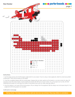
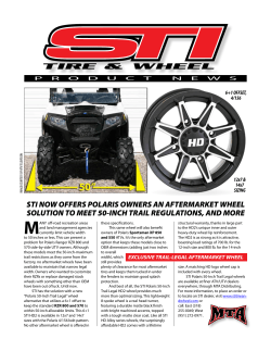
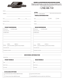


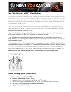

© Copyright 2026