
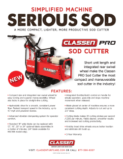
A 900 C â A 904 C Wheeled Excavator
Wheeled Excavator A 900 C – A 904 C Operating Weight: 18,500 - 19,000 kg Engine Output: 95 kW / 129 HP Bucket Capacity: 0.32 - 1.05 m³ 20,400 - 20,600 kg 105 kW / 143 HP 0.55 - 1.20 m³ A 900 C Operating Weight: 18,500 - 19,000 kg Engine Output: 95 kW / 129 HP Bucket Capacity: 0.32 - 1.05 m³ A 904 C Operating Weight: 20,400 - 20,600 kg Engine Output: 105 kW / 143 HP Bucket Capacity: 0.55 - 1.20 m³ 2 A 900 C / A 904 C Litronic Reliability Comfort Liebherr hydraulic excavators have been designed and built to withstand the toughest of conditions at the building site. Their rugged design, high-tensile materials and individual components ensure maximum availability and long lifeexpectancy. Largely dimensioned and ergonomically designed, the Liebherr excavator cab features an operator’s seat which can be individually adjusted, as well as clearly arranged control instruments and ideal all-round view. Automatic air-conditioning guarantees an optimum temperature in the Liebherr Feel-Good cab at all times. Performance Liebherr wheel excavators have been designed for maximum productivity. Maximum digging performances, high lift capacities and quick working cycles are prerequisite for efficient building site operation, and a wide variety of attachments optimize every excavator application. Economy The Liebherr-Litronic-System increases machine performance, reduces fuel consumption and minimises service and maintenance costs. A 900 C / A 904 C Litronic 3 Lubrication system • The semi-automatic central lubrication system fitted as standard saves on time-consuming greasing. • Lubricating without interrupting work for higher productivity. 4 A 900 C / A 904 C Litronic Reliability Liebherr construction machinery is proven all over the world every day on the most diverse of building sites. Many years of experience as the world’s largest manufacturer of rubber-tyre excavators, continuous development and the introduction of the latest technology are evident in every machine, guaranteeing absolute safety during applications. With its rugged design, and featuring Liebherr components, the Liebherr hydraulic excavators have been designed for extremely long life-expectancy. Quality in detail Liebherr components Components such as engine, hydraulic cylinders, swing gear and electric parts have been specially designed, tested and manufactured by Liebherr for construction machinery. Parts including engines and pumps for example, are already being synchronized with each other as early as the construction phase, yielding a constant standard of quality. Functional safety Safety-orientated components, fitted as standard, allow high availability. The operator can thus concentrate fully on the task at hand, due to the integrated on-board electronics performing a constant balancing of pre-defined set data. Filtering of metallic filings by the magnetic rod, fitted in the hydraulic system as standard, increases lifeexpectancy of the hydraulic components and the oil. Rugged attachments Working attachment The durable attachments have been designed for the toughest of applications. All components are optimised to the FEM methods and the hoist cylinders feature bearings on both sides. Piping The hydraulic lines are arranged optimally to safeguard against damage. The electric cabling is made with high-grade materials, thus guaranteeing a reliable supply to the consumer. Liebherr hydraulic cylinders Functional safety • Specific size for each machine. • Essential operating data is stored and can be recalled at any time. • High-grade surface coating of the piston rods. • All Liebherr cylinders feature special long-life sealing systems. • Shock absorption at both sides in the working cylinders. • Control and monitoring functions increase functional safety of the machine. • Four fixed working modes for output discharge facilitate an effective and efficient operation: – Eco-Mode: for high output at big fuel savings – Power-Mode: for heavy-duty digging-and loading performance under severe conditions – Lift-Mode: for precise handling of heavy loads – Fine-Mode: for fine control at precision work A 900 C / A 904 C Litronic 5 Liebherr diesel engine • Long life-expectancy, expansive cylinder capacity and increased weight . • According to level IIIA / Tier 3. • Specially designed for construction machinery operation. • Oil supply even with extremetilt angle of 45°. 6 A 900 C / A 904 C Litronic Performance Liebherr wheel excavators have been designed for maximum productivity. Perfectly harmonized, the Liebherr-developed and Liebherr-manufactured components including diesel engine, hydraulic pump and motor, as well as swing gear and cylinders, guarantee maximum performance. Tremendous digging and breakout forces, extensive lifting capacities and quick working and travel movements are thus resulted. Innovative solutions Intelligent undercarriage The drive unit on the A 900C has been fully integrated in the sturdy undercarriage. Intelligently built and robust in service, the undercarriage offers the travel drive unit the best possible protection from debris, stones and soil. Its advantages are perfect all-terrain compatibility and extremely high ground clearance. Multitude of attachments Liebherr provide an individual, application-related range of diverse attachments. Angled and straight mono boom combinable with different stick length. Extensive lifting capacities Lifting heavy loads is one of the everyday requirements of wheeled excavators. These requirements are endorsed via an intelligent concept of uppercarriage sectioning together with the positioning of the Liebherr engine, mounted at a transversal angle directly in front of the counterweight. Separate hoist cylinder bearing points at the upper end of the basic boom also increase the lifting capacities considerably. High productivity Quick working cycles High swing torque – attained as a result of the Liebherr swing ring featuring internal teeth and swing drive, specially designed to increase the torque. Performance without compromise Maximum performance and maximum forces are available to the operator at all times. Rugged undercarriage Litronic • Various undercarriage designs featuring welded, durable outriggers allow safe positioning, optimum stability, and long life-expectancy of the machine for every application. • Increases productivity of the excavator. • Prop-up blade / dozing blade in box-type design – only two bearing points for high torsional resistance. • Allows maximum sensitivity and as many overlapping movements as are required. • Reduces fuel consumption. • Reduces service costs and eases operation. • Optional piston rod guard for plate and claw support. A 900 C / A 904 C Litronic 7 Large-sized cab • Adjustable steering column. • Operator’s seat, adjustable in height and can also be adapted to the individual weight of the operator. • Consoles with or without possibility of horizontal adjustment. • Large roof window. • Sun blinds. 8 A 900 C / A 904 C Litronic Comfort The excavator operator is provided with an ergonomically-arranged working area within Liebherr hydraulic excavator cabs. All switches and functions are logically laid out, and operator’s seat, steering column and consoles can be adjusted individually. Conditioning and concentration can thus be maintained throughout the entire working day, guaranteeing constant, maximum productivity of the operator. Mobile comfort Easy access Wide steps, ergonomically-positioned handles and adjustable steering column allow an easy access into the Liebherr operator’s cab. Optimum visibility A well-thought-out design of the uppercarriage, featuring large glass panels and rounded edges, increase overall visibility and guarantees a safe overview of the entire working area. Pleasant surroundings The low engine speed and extensive silencing system and enhanced hydraulic components supply a pleasant noise level inside the cab. Maintenance features Easy maintenance Semi-Automatical Central lubrication for swing gear and main parts of the attachment. Ease of operation A shut-off valve, fitted to the hydraulic tank as standard, disconnects the system and guarantees ease of maintenance to the hydraulic system. Easy access Large maintenance flaps allow comfortable and safe access to all maintenance points. Storage compartment – Everything has its place Fully-automatic air-conditioning system • Sufficient storage space for a commercially-approved cooler box behind the operator’s seat. • The air-conditioning system, fitted as standard, offers the same comfort as that of a regular car. • Drinks holder and storage compartment in operator’s cab. • Large storage box behind the operator’s cab. • Two standard tool boxes in the undercarriage. • Two sensors for precise temperature regulation. • Ventilation flaps are controlled via keys. • Reheat function for quick dehumidifying / defrosting of the windshield. A 900 C / A 904 C Litronic 9 Hydrostatic fan drive • Accelerated warm-up period. • Guaranteed constant oil quality as a result of constant oil temperature. • Increased life-expectancy of drive components. • The fan only runs at the output required, thus conserving fuel and reducing the noise level considerably. 10 A 900 C / A 904 C Litronic Economy Liebherr wheeled excavators are machines that combine high productivity with excellent levels of economy - and all this comes as standard from the factory. Easy access to components, as well as the proven service offer allows maintenance tasks to be performed in the shortest of times, thus reducing operating costs considerably. Low operating costs Solid Liebherr Engine Maximum power of the engine is generated even when running at minimum speed. This allows the necessary output without limitation, whereby the torque which is available is ample for the level required, resulting in high productivity with low consumption. Automatic idle If no working or travel movements are being performed, the shiftable function reduces the engine speed to idle, which in turn reduces fuel consumption and emission levels. Intelligent hydraulic management The state-of-the-art hydraulic system allows conversion of the maximum engine output into high force or speed, as required. The maximum possible forces are available at all times. Investment for the future Service-orientated • Service points of the engine – such as filter or filling amount displays are easily accessible and can be easily reached from the maintenance platform. • The magnetic rod on the hydraulic oil return flow increases life-expectancy of the oil. • semi-Automatical Central lubrication for swing gear and main parts of the attachment allowing quicker maintenance. Service A fast response when service is required minimises downtime and ensures that schedules can be met. This is made possible by a high spare part availability. Service engineers trained by Liebherr carry out service and maintenance work on the spot, quickly and in accordance with the manufacturer’s specifications. High resale values Liebherr excavators are built with high-grade materials and quality production to provide a long-term operational life-span, thus guaranteeing maximum resale values. Modular quick-change system made by Liebherr • Likufix – connects all hydraulically mounted tools without having to leave the operator’s cab, maximum productivity due to tool change being performed in a matter of seconds. • The suitable digging tool for every application. Your machine is a multi-functional tool carrier and will pay for itself very quickly indeed. • Mechanic and hydraulic Liebherr quick-change adapter. A 900 C / A 904 C Litronic 11 Technical Data Engine Rating per ISO 9249 A 900 C litronic` ���������� 95 kW (129 HP) at 1,800 RPM A 904 C litronic` ���������� 105 kW (143 HP) at 1,800 RPM Model������������������������������� Liebherr D 934 S according to stage IIIA / Tier 3 Type�������������������������������� 4 cylinder in-line Bore/Stroke������������������ 122/136 mm Displacement���������������� 6.4 l Engine operation����������������� 4-stroke diesel unit pump system turbo-charged and after-cooled reduced emissions Cooling system������������������� water-cooled and integrated motor oil cooler rimary and Air cleaner������������������������� dry-type air cleaner with pre-cleaner, p safety elements Fuel tank A 900 C litronic` ���������� 290 l A 904 C litronic` ���������� 350 l Engine idling ���������������������� sensor controlled Electrical system Voltage����������������������� 24 V Batteries���������������������� 2 x 110 Ah/12 V Alternator��������������������� three phase current 28 V/80 A Hydraulic System Hydraulic pump A 900 C litronic` ���������� Liebherr, variable displacement, swashplate pump Max. flow��������������������� 300 l/min. A 904 C litronic` ���������� Liebherr, variable displacement, swashplate double pump Max. flow��������������������� 2 x 189 l/min. �������� 350 bar Max. hydr. pressure Hydraulic pump ����������� Liebherr-Synchron-Comfort-system (LSC) with regulation and control electronic horsepower regulation, pressure cutoff, load sensing and torque controlled swing drive priority Hydraulic tank capacity��������� 175 l Hydraulic system capacity A 900 C litronic` ���������� max. 290 l A 904 C litronic` ���������� max. 320 l Filtration ��������������������������� main return filter with integrated partial micro filtration (5 µm) Cooling system������������������� compact cooler, consisting of a water cooler, sandwiched with hydraulic oil cooler, fuel cooler and after-cooler cores and hydrostatically driven fan Modes������������������������������can also be adjusted by the operator to adjust engine and hydraulic performance to match job conditions (Note: All modes provide full max. power) ��������������������������� for precise lifting tasks LIFT �������������������������� for precision work at high speed i.e. grading FINE ECO��������������������������� for most economic performance at best environmental conditions POWER ���������������������� for max. output RPM adjustment ����������������� stepless adjustment of engine output via rpm Hydraulic Controls Power distribution���������������� via control valve with integrated safety valves, simultaneous and independent operation of travel drive, swing drive and work Control type Attachment and swing����� proportional via joystick levers Travel������������������������� proportional via foot pedal Additional functions�������������� via switch and/or proportional foot pedals 12 A 900 C Litronic A 904 C Litronic Swing Drive Drive�������������������������������� Liebherr swashplate motor with torque control and integrated brake valve Transmission���������������������� Liebherr compact planetary reduction gear Swing ring������������������������� Liebherr sealed single race ball bearing swing ring, internal teeth Swing speed���������������������� 0 – 9.0 RPM Swing torque A 900 C litronic` ���������� 42 kNm A 904 C litronic` ���������� 46 kNm Holding brake��������������������� wet discs (spring applied – pressure released) Operator’s Cab Cab��������������������������������� resiliently mounted, sound insulated, tinted windows, front window stores overhead, door with sliding window, large roof window, sun visor ������������������� fully adjustable, shockabsorbing suspension, Operator’s seat adjustable to operator’s weight and size, 6-way adjustable Liebherr seat Joysticks��������������������������� integrated into adjustable seat consoles Monitoring������������������������� menu driven query of current operating conditions via the LCD display. Automatic monitoring, display, warning (acoustical and optical signal) and saving machine data, for example, engine overheating, low engine oil pressure or low hydraulic oil level Air conditioning������������������� standard air conditioning, combined cooler/heater, additional dust filter in fresh air/recirculated Noise emission ISO 6396 LpA (inside cab)�������������� = 72 dB(A) A 900 C litronic` = 73 dB(A) A 904 C litronic` 2000/14/EC LWA (surround noise) ������� = 99 dB(A) A 900 C litronic` = 100 dB(A) A 904 C litronic` Undercarriage Drive�������������������������������� variable flow swashplate motor with automatic brake valve Transmission���������������������� oversized two speed power shift transmission with additional creeper speed Travel speed���������������������� 0 – 2.5 km/h (creeper speed off road) 0 – 5.0 km/h (off road) 0 – 9.0 km/h (creeper speed on road) 0 – 20.0 km/h (road travel) 0 – 30.0 km/h Speeder Axles�������������������������������� automatic or operator controlled front axle oscillation lock Brakes������������������������������ steering and rigid axle with wet, maintenance-free multi disc brakes with minimized backlash. Spring applied/pressure released parking brake integrated into gear box ����������������������� stabilizing blade (adjustable during travel for Stabilization dozing) 2 pt. outriggers rear and stabilizing blade front Attachment Hydraulic cylinders��������������� Liebherr cylinders with special seal system. Shock absorption Pivots������������������������������� sealed, low maintenance Dimensions E D A C W H K Q H0483 V X B B1 J2 I2 T2 A 900 C A B B1 B2 C D E H I2 J2 K L M Q T1 T2 U E = Tail radius Tires 10.00-20 U L M B B2 B1 T1 litronic` mm 2,550 2,550 3,692 2,550 3,157 2,260 2,330 2,465 380 584 1,233 2,540 1,100 358 1,047 1,153 4,740 A 904 C H0490 litronic` mm 2,550 2,550 3,695 2,550 3,160 2,471 2,514 2,468 458 589 1,236 2,750 1,250 344 1,190 1,409 5,349 A 900 C litronic` Stick Mono Boom 5.00 m blade + 2 pt outr. mm m V 2.45 5,400 2.65 5,650* W 2.45 3,100 2.65 3,150* X 2.45 8,400 2.65 8,750* Straight Mono Boom 5.50 m blade + 2 pt outr. mm 6,200 6,100 2,950 3,050 8,900 8,900 A 904 C litronic` Straight Mono Boom Stick Mono Boom 5.30 m 5.50 m blade blade + 2 pt outr. + 2 pt outr. mm mm m V 2.45 6,400 6,150 2.65 6,250* 6,650* W 2.45 3,200 3,050 2.65 3,250* 3,150* X 2.45 9,600 9,200 2.65 9,600* 9,700* Dimensions are with attachment over steering axle * Attachment over digging axle for shorter transport dimensions A 900 C Litronic A 904 C Litronic 13 Backhoe Bucket A 900 C litronic` with Mono Boom 5.00 m m ft 30 Digging Envelope H0706 10 with Quick Coupler Stick length Max. digging depth Max. reach at ground level Max. dumping height Max. teeth height Min. attachment radius 9 8 25 7 20 6 5 15 2 5 1 0 Operating Weight -1 -5 The operating weight includes the basic machine with 8 tires plus intermediate rings, mono boom 5.00 m, stick 2.45 m, quick coupler 48 and bucket 1,050 mm/0.80 m3. -2 -3 -10 Undercarriage versions A 900 C litronic` with stabilizer blade + 2 pt. outriggers -4 -15 Weight 18,500 kg -5 1 10 9 30 Capacity ISO 74511) mm 5002) 6502) 8502) 1,0502) 1,2502) 5003) 6503) 8503) 1,0503) 1,2503) 5004) 6504) 8504) 1,0504) 1,2504) m3 0.32 0.45 0.60 0.80 0.95 0.32 0.45 0.60 0.80 0.95 0.34 0.45 0.65 0.85 1.05 8 7 25 6 20 5 4 15 2 3 10 2 1 5 0m 0 ft Machine stability per ISO 10567* (75 % of tipping capacity) Stabilizers raised Weight Cutting width Buckets Stabilizer blade + 2 pt. outr. down Stick length (m) kg 290 400 430 510 560 330 440 480 570 630 280 380 410 490 530 Stick length (m) 2.45 2.65 2.45 2.65 Y Y Y Y Y Y Y Y Y Y Y Y Y V Y Y V y Y Y Y Y Y Y Y Y Y Y Y Y Y Y Y V Y Y y y Y Y Y Y Y Y Y Y Y Y Y Y Y Y V V Y Y y y Y Y *Indicated loads are based on ISO 10567 and do not exceed 75 % of tipping or 87 % of hydraulic capacity, max. stick length without quick coupler, lifted 360° on firm with blocked oscillating axle 1)comparable with SAE (heaped) 2)Bucket with teeth 3) Bucket with teeth in HD-version 4) Bucket with cutting edge (also available in HD-version) Buckets with 500 mm cutting width with limited digging depth Max. material weight 14 2 2.65 5.90 9.20 6.40 9.25 3.05 Digging Forces 3 0 1 2.45 5.70 9.00 6.25 9.10 3.05 without Quick Coupler 1 2 Max. digging force (ISO 6015) kN 76.0 71.6 t 7.7 7.3 Max. breakout force (ISO 6015) kN 98.4 98.4 t 10.0 10.0 Max. breakout force with ripper bucket 125.7 kN (12.8 t) Max. possible digging force (stick 1.70 m) 99.4 kN (10.1 t) 4 10 m m m m m m Y = ≤ 1.8 t/m3, A 900 C Litronic A 904 C Litronic V = ≤ 1.5 t/m3, y = ≤ 1.2 t/m3, v = not authorized Lift Capacities A 900 C litronic` with Mono Boom 5.00 m Stick 2.45 m 3.0 m m 9.0 7.5 6.0 4.5 3.0 1.5 0 – 1.5 – 3.0 – 4.5 Undercarriage Stabilizers raised Blade + 2 pt. down Stabilizers raised Blade + 2 pt. down Stabilizers raised Blade + 2 pt. down Stabilizers raised Blade + 2 pt. down Stabilizers raised Blade + 2 pt. down Stabilizers raised Blade + 2 pt. down Stabilizers raised Blade + 2 pt. down Stabilizers raised Blade + 2 pt. down Stabilizers raised Blade + 2 pt. down Stabilizers raised Blade + 2 pt. down 4.5 m 6.0 m 7.5 m m 7.2 8.8* 5.2* 5.2* 5.9 5.9* 5.9 8.6* 6.1 11.2* 8.8* 8.8* 5.2* 5.2* 5.9* 5.9* 8.6* 8.6* 11.2* 11.2* 3.9 5.7* 3.5 6.5 3.3 6.2 3.2 6.1 3.3 6.2 5.7* 5.7* 6.1 7.2* 5.8 8.1* 5.8 8.3* 5.8 7.5* 2.8 3.2* 2.7 4.0* 2.5 4.4 2.3 4.2 2.2 4.0 2.2 4.0 2.2 4.1 3.2* 3.2* 4.0* 4.0* 4.1 4.6* 3.9 5.3* 3.8 5.8* 3.8 5.9* 3.8 5.3* 1.7 2.9* 1.7 3.0 1.6 2.9 2.1* 2.1* 1.8* 1.8* 1.8* 1.8* 1.6 1.8* 1.5 2.0* 1.6 2.3* 1.7 2.9* 2.2 3.9 3.6 5.3* 2.9 2.9* 2.8 3.7* 2.8 3.3* 2.1* 2.1* 1.8* 1.8* 1.8* 1.8* 1.8* 1.8* 2.0* 2.0* 2.3* 2.3* 2.9* 2.9* 3.7 4.3* 5.3* 5.3* 5.2 6.6 7.3 7.8 7.9 7.7 7.1 6.1 4.5 Stick 2.65 m 3.0 m m 9.0 7.5 6.0 4.5 3.0 1.5 0 – 1.5 – 3.0 – 4.5 Undercarriage Stabilizers raised Blade + 2 pt. down Stabilizers raised Blade + 2 pt. down Stabilizers raised Blade + 2 pt. down Stabilizers raised Blade + 2 pt. down Stabilizers raised Blade + 2 pt. down Stabilizers raised Blade + 2 pt. down Stabilizers raised Blade + 2 pt. down Stabilizers raised Blade + 2 pt. down Stabilizers raised Blade + 2 pt. down Stabilizers raised Blade + 2 pt. down Height 4.5 m 6.0 m 7.5 m m 7.3 8.1* 6.0* 6.0* 5.9 6.0* 5.9 8.3* 6.0 11.5* 6.3 8.6* 8.1* 8.1* 6.0* 6.0* 6.0* 6.0* 8.3* 8.3* 11.5* 11.5* 8.6* 8.6* Can be slewed through 360° 3.9 5.4* 3.5 6.5 3.3 6.2 3.2 6.1 3.2 6.1 3.5 5.7* 5.4* 5.4* 6.1 7.0* 5.8 8.0* 5.7 8.2* 5.8 7.7* 5.7* 5.7* 2.8 3.2* 2.7 3.8* 2.5 4.4 2.3 4.2 2.2 4.0 2.1 4.0 2.2 4.0 3.2* 3.2* 3.8* 3.8* 4.1 4.5* 3.9 5.2* 3.8 5.8* 3.7 5.9* 3.8 5.4* In longitudinal position of undercarriage 1.8 1.8* 1.7 3.1 1.6 3.0 1.6 2.9 1.9* 1.9* 1.7* 1.7* 1.6* 1.6* 1.5 1.7* 1.5 1.8* 1.5 2.0* 1.6 2.5* 2.0 3.7* 3.2 5.1* 1.8* 1.8* 2.9 3.2* 2.8 4.0* 2.7 3.9* Max. reach 1.9* 1.9* 1.7* 1.7* 1.6* 1.6* 1.7* 1.7* 1.8* 1.8* 2.0* 2.0* 2.5* 2.5* 3.5 3.7* 5.1* 5.1* 5.5 6.8 7.6 8.0 8.1 7.8 7.3 6.4 4.8 * Limited by hydr. capacity The lift capacities on the load hook of the Liebherr quick coupler 48 without working tool are stated in metric tons (t) and are valid on a firm, level supporting surface with blocked oscillating axle. These capacities can be slewed through 360° with the undercarriage in the transverse position. Capacities in the longitudinal position of the undercarriage (+/– 15°) are specified over the steering axle with the stabilizers raised and over the rigid axle with the stabilizers down. Indicated loads comply with the ISO 10567 standard and do not exceed 75 % of tipping or 87 % of hydraulic capacity, or are limited by the permissible load of the load hook on the quick coupler (max. 12 t). Without the quick coupler, lift capacities will increase by up to 226 kg. In accordance with the harmonised EU Standard EN 474-5, hydraulic excavators used for lifting operations must be equipped with pipe rupture protection devices on the hoist cylinders and an overload warning device. A 900 C Litronic A 904 C Litronic 15 Backhoe Bucket A 900 C litronic` with Straight Mono Boom 5.50 m ft 35 m 11 Digging Envelope H0707 with Quick Coupler Stick length Max. digging depth Max. reach at ground level Max. dumping height Max. teeth height Min. attachment radius 10 30 9 8 25 7 20 1 2 m 2.45 2.65 m 5.55 5.75 m 9.60 9.80 m 7.30 7.45 m 10.35 10.55 m 3.20 3.25 6 Digging Forces 5 15 without Quick Coupler 1 2 Max. digging force (ISO 6015) kN 76.0 71.6 t 7.7 7.3 Max. breakout force (ISO 6015) kN 98.4 98.4 t 10.0 10.0 Max. breakout force with ripper bucket 125.7 kN (12.8 t) Max. possible digging force (stick 1.70 m) 99.4 kN (10.1 t) 4 10 3 2 5 1 0 0 Operating Weight -1 -5 The operating weight includes the basic machine with 8 tires plus intermediate rings, straight mono boom 5.50 m, stick 2.45 m, quick coupler 48 and bucket 1,050 mm/0.80 m3. -2 -3 -10 Undercarriage versions A 900 C litronic` with stabilizer blade + 2 pt. outriggers -4 -15 -5 1 11 10 35 Cutting width Capacity ISO 74511) Buckets mm 5002) 6502) 8502) 1,0502) 1,2502) 5003) 6503) 8503) 1,0503) 1,2503) 5004) 6504) 8504) 1,0504) 1,2504) m3 0.32 0.45 0.60 0.80 0.95 0.32 0.45 0.60 0.80 0.95 0.34 0.45 0.65 0.85 1.05 9 30 8 7 6 25 2 5 20 4 15 3 10 2 1 5 0m 0 ft Machine stability per ISO 10567* (75 % of tipping capacity) Stabilizers raised Weight -6 -20 Stabilizer blade + 2 pt. outr. down Stick length (m) kg 290 400 430 510 560 330 440 480 570 630 280 380 410 490 530 Weight 18,600 kg Stick length (m) 2.45 2.65 2.45 2.65 Y Y Y Y Y Y Y Y Y Y Y Y y y Y Y v v Y Y Y Y Y Y Y Y Y Y Y Y Y Y y y Y Y v v Y Y Y Y Y Y Y Y Y Y Y V Y Y y y Y Y v v Y V *Indicated loads are based on ISO 10567 and do not exceed 75 % of tipping or 87 % of hydraulic capacity, max. stick length without quick coupler, lifted 360° on firm with blocked oscillating axle 1)comparable with SAE (heaped) 2)Bucket with teeth 3) Bucket with teeth in HD-version 4) Bucket with cutting edge (also available in HD-version) Buckets with 500 mm cutting width with limited digging depth Max. material weight 16 Y = ≤ 1.8 t/m3, A 900 C Litronic A 904 C Litronic V = ≤ 1.5 t/m3, y = ≤ 1.2 t/m3, v = not authorized Lift Capacities A 900 C litronic` with Straight Mono Boom 5.50 m Stick 2.45 m 3.0 m m 9.0 7.5 6.0 4.5 3.0 1.5 0 – 1.5 – 3.0 – 4.5 Undercarriage Stabilizers raised Blade + 2 pt. down Stabilizers raised Blade + 2 pt. down Stabilizers raised Blade + 2 pt. down Stabilizers raised Blade + 2 pt. down Stabilizers raised Blade + 2 pt. down Stabilizers raised Blade + 2 pt. down Stabilizers raised Blade + 2 pt. down Stabilizers raised Blade + 2 pt. down Stabilizers raised Blade + 2 pt. down Stabilizers raised Blade + 2 pt. down 4.5 m 6.0 m 7.5 m m 5.7 6.1* 5.9 9.3* 6.1* 6.1* 9.3* 9.3* 4.2 5.3* 3.7 6.7* 3.3 6.2 3.1 6.0 3.1 6.0 3.1 6.0 5.3* 5.3* 6.4 6.7* 5.9 7.8* 5.7 8.2* 5.6 7.8* 5.7 6.8* 2.4* 2.4* 2.8 4.1* 2.6 4.5* 2.4 4.3 2.2 4.1 2.1 3.9 2.1 3.9 2.1 3.9 2.4* 2.4* 4.1* 4.1* 4.3 4.5* 4.1 5.1* 3.8 5.6* 3.7 5.9* 3.6 5.7* 3.7 4.9* 1.8 3.1 1.7 3.0 1.6 2.9 1.5 2.9 1.5 2.8 2.9 3.4* 2.9 4.3* 2.8 4.5* 2.7 4.6* 2.7 4.3* 2.0* 2.0* 1.8* 1.8* 1.6 1.8* 1.4 1.8* 1.3 1.9* 1.3 2.2* 1.4 2.6* 1.7 3.2 2.0* 2.0* 1.8* 1.8* 1.8* 1.8* 1.8* 1.8* 1.9* 1.9* 2.2* 2.2* 2.5 2.6* 3.0 3.4* 2.4* 2.4* 1.9* 1.9* 1.7* 1.7* 1.5 1.6* 1.3 1.6* 1.2 1.7* 1.3 1.9* 1.4 2.3* 1.6 3.0* 2.5 3.8* 2.4* 2.4* 1.9* 1.9* 1.7* 1.7* 1.6* 1.6* 1.6* 1.6* 1.7* 1.7* 1.9* 1.9* 2.3* 2.3* 2.9 3.0* 3.8* 3.8* 6.1 7.3 8.0 8.4 8.5 8.3 7.8 6.9 Stick 2.65 m 3.0 m m 9.0 7.5 6.0 4.5 3.0 1.5 0 – 1.5 – 3.0 – 4.5 Undercarriage Stabilizers raised Blade + 2 pt. down Stabilizers raised Blade + 2 pt. down Stabilizers raised Blade + 2 pt. down Stabilizers raised Blade + 2 pt. down Stabilizers raised Blade + 2 pt. down Stabilizers raised Blade + 2 pt. down Stabilizers raised Blade + 2 pt. down Stabilizers raised Blade + 2 pt. down Stabilizers raised Blade + 2 pt. down Stabilizers raised Blade + 2 pt. down Height 4.5 m 6.0 m 7.5 m m 3.5* 3.5* 5.7 5.9* 5.8 9.1* Can be slewed through 360° 3.5* 3.5* 5.9* 5.9* 9.1* 9.1* 4.2 5.1* 3.8 6.4* 3.3 6.3 3.1 6.0 3.0 5.9 3.1 6.0 3.3 5.0* 5.1* 5.1* 6.4 6.4* 5.9 7.6* 5.6 8.1* 5.6 7.9* 5.6 6.9* 5.0* 5.0* 2.8* 2.8* 2.8 3.8* 2.6 4.3* 2.4 4.3 2.2 4.1 2.1 3.9 2.0 3.8 2.0 3.9 2.8* 2.8* 3.8* 3.8* 4.3 4.3* 4.1 4.9* 3.8 5.5* 3.7 5.8* 3.6 5.7* 3.6 5.1* In longitudinal position of undercarriage 1.7* 1.7* 1.8 3.1 1.7 3.0 1.6 2.9 1.5 2.8 1.5 2.8 1.7* 1.7* 3.0 3.5* 2.9 4.2* 2.7 4.4* 2.7 4.5* 2.6 4.3* Max. reach 4.4 6.4 7.5 8.2 8.6 8.7 8.5 8.0 7.2 5.5 * Limited by hydr. capacity The lift capacities on the load hook of the Liebherr quick coupler 48 without working tool are stated in metric tons (t) and are valid on a firm, level supporting surface with blocked oscillating axle. These capacities can be slewed through 360° with the undercarriage in the transverse position. Capacities in the longitudinal position of the undercarriage (+/– 15°) are specified over the steering axle with the stabilizers raised and over the rigid axle with the stabilizers down. Indicated loads comply with the ISO 10567 standard and do not exceed 75 % of tipping or 87 % of hydraulic capacity, or are limited by the permissible load of the load hook on the quick coupler (max. 12 t). Without the quick coupler, lift capacities will increase by up to 226 kg. In accordance with the harmonised EU Standard EN 474-5, hydraulic excavators used for lifting operations must be equipped with pipe rupture protection devices on the hoist cylinders and an overload warning device. A 900 C Litronic A 904 C Litronic 17 Backhoe Bucket A 904 C litronic` with Mono Boom 5.30 m ft m 10 30 Digging Envelope H0710 with Quick Coupler Stick length Max. digging depth Max. reach at ground level Max. dumping height Max. teeth height Min. attachment radius 9 8 25 7 20 6 5 15 2 1 0 0 Operating Weight -1 -5 The operating weight includes the basic machine with 8 tires plus intermediate rings, mono boom 5.30 m, stick 2.65 m, quick coupler 48 and bucket 1,250 mm/1.00 m3. -2 -3 -10 Undercarriage versions A 904 C litronic` with stabilizer blade + 2 pt. outriggers -4 -15 Weight 20,400 kg -5 -6 -20 -7 1 10 9 30 Capacity ISO 74511) mm 6502) 8502) 1,0502) 1,2502) 1,4002) 6503) 8503) 1,0503) 1,2503) 1,4003) 6504) 8504) 1,0504) 1,2504) 1,4004) m3 0.55 0.60 0.80 1.00 1.15 0.55 0.60 0.80 1.00 1.15 0.60 0.65 0.85 1.05 1.20 8 7 25 6 20 5 2 4 15 3 10 2 1 5 0m 0 ft Machine stability per ISO 10567* (75 % of tipping capacity) Stabilizers raised Weight Cutting width Buckets Stabilizer blade + 2 pt. outr. down Stick length (m) kg 510 550 630 730 790 570 620 710 820 880 430 590 670 770 840 Stick length (m) 2.45 2.65 2.45 2.65 Y Y Y Y Y Y Y Y V V Y Y y v Y Y v v Y Y Y Y Y Y Y Y Y Y V y Y Y v v Y Y v v Y Y Y Y Y Y Y Y Y Y V y Y Y v v Y Y v v Y Y *Indicated loads are based on ISO 10567 and do not exceed 75 % of tipping or 87 % of hydraulic capacity, max. stick length without quick coupler, lifted 360° on firm with blocked oscillating axle 1)comparable with SAE (heaped) 2)Bucket with teeth 3) Bucket with teeth in HD-version 4) Bucket with cutting edge (also available in HD-version) Max. material weight 18 2 2.65 6.20 9.50 6.55 9.45 3.10 Digging Forces 3 5 1 2.45 6.00 9.30 6.45 9.30 3.10 without Quick Coupler 1 2 Max. digging force (ISO 6015) kN 90.9 85.8 t 9.3 8.7 Max. breakout force (ISO 6015) kN 133.2 133.2 t 13.6 13.6 Max. breakout force with ripper bucket 156.9 kN (16.0 t) Max. possible digging force (stick 1.70 m) 117.2 kN (11.9 t) 4 10 m m m m m m Y = ≤ 1.8 t/m3, A 900 C Litronic A 904 C Litronic V = ≤ 1.5 t/m3, y = ≤ 1.2 t/m3, v = not authorized Lift Capacities A 904 C litronic` with Mono Boom 5.30 m Stick 2.45 m 3.0 m m 9.0 7.5 6.0 4.5 3.0 1.5 0 – 1.5 – 3.0 – 4.5 Undercarriage Stabilizers raised Blade + 2 pt. down Stabilizers raised Blade + 2 pt. down Stabilizers raised Blade + 2 pt. down Stabilizers raised Blade + 2 pt. down Stabilizers raised Blade + 2 pt. down Stabilizers raised Blade + 2 pt. down Stabilizers raised Blade + 2 pt. down Stabilizers raised Blade + 2 pt. down Stabilizers raised Blade + 2 pt. down Stabilizers raised Blade + 2 pt. down 4.5 m 6.0 m 7.5 m m 7.6 11.6* 11.6* 11.6* 6.1* 6.1* 6.3 9.3* 6.4 13.5 6.8 11.2* 6.1* 6.1* 9.3* 9.3* 13.9* 13.9* 11.2* 11.2* 4.3 7.1* 3.8 7.0 3.5 6.7 3.4 6.6 3.5 6.6 3.7 6.9 7.1* 7.1* 7.1 9.0* 6.8 10.1* 6.7 10.3* 6.7 9.7* 7.0 7.6* 3.1 4.4* 3.0 4.8* 2.8 4.8 2.5 4.6 2.4 4.4 2.3 4.3 2.3 4.3 4.4* 4.4* 4.8* 4.8* 4.9 5.6* 4.6 6.5* 4.4 7.2* 4.3 7.5* 4.4 7.0* 2.0 3.0* 1.9 3.4 1.8 3.3 1.7 3.2 2.6* 2.6* 2.4* 2.4* 1.9 2.4* 1.7 2.4* 1.6 2.6* 1.6 2.9 1.7 3.2 2.1 3.9 3.3 6.0 3.0* 3.0* 3.4 4.8* 3.3 5.4* 3.2 5.8* 2.6* 2.6* 2.4* 2.4* 2.4* 2.4* 2.4* 2.4* 2.6* 2.6* 3.0 3.0* 3.2 3.8* 3.9 5.5* 6.1 6.8* 5.6 6.9 7.6 8.0 8.1 7.9 7.4 6.5 4.9 Stick 2.65 m 3.0 m m 9.0 7.5 6.0 4.5 3.0 1.5 0 – 1.5 – 3.0 – 4.5 Undercarriage Stabilizers raised Blade + 2 pt. down Stabilizers raised Blade + 2 pt. down Stabilizers raised Blade + 2 pt. down Stabilizers raised Blade + 2 pt. down Stabilizers raised Blade + 2 pt. down Stabilizers raised Blade + 2 pt. down Stabilizers raised Blade + 2 pt. down Stabilizers raised Blade + 2 pt. down Stabilizers raised Blade + 2 pt. down Stabilizers raised Blade + 2 pt. down Height 4.5 m 6.0 m 7.5 m m 7.8 10.7* 5.1* 5.1* 6.1* 6.1* 6.2 9.0* 6.4 13.0* 6.6 11.8* 10.7* 10.7* 5.1* 5.1* 6.1* 6.1* 9.0* 9.0* 13.0* 13.0* 11.8* 11.8* Can be slewed through 360° 4.3 6.8* 3.8 7.0 3.5 6.7 3.4 6.5 3.4 6.6 3.6 6.8 6.8* 6.8* 7.2 8.7* 6.8 9.9* 6.7 10.3* 6.7 9.8* 6.9 8.0* 3.1 4.1* 3.0 4.6* 2.8 4.8 2.5 4.6 2.4 4.4 2.3 4.3 2.3 4.3 4.1* 4.1* 4.6* 4.6* 4.9 5.4* 4.6 6.4* 4.4 7.1* 4.3 7.4* 4.3 7.1* In longitudinal position of undercarriage 2.0 3.4* 1.9 3.4 1.8 3.3 1.7 3.2 1.7 3.1 2.4* 2.4* 2.2* 2.2* 1.8 2.2* 1.6 2.2* 1.5 2.4* 1.5 2.7* 1.6 3.1 2.0 3.7 2.9 5.4 3.4* 3.4* 3.4 4.9* 3.3 5.3* 3.2 5.7* 3.1 4.2* Max. reach 2.4* 2.4* 2.2* 2.2* 2.2* 2.2* 2.2* 2.2* 2.4* 2.4* 2.7* 2.7* 3.1 3.4* 3.7 4.7* 5.5 6.6* 5.9 7.1 7.8 8.2 8.3 8.1 7.6 6.7 5.2 * Limited by hydr. capacity The lift capacities on the load hook of the Liebherr quick coupler 48 without working tool are stated in metric tons (t) and are valid on a firm, level supporting surface with blocked oscillating axle. These capacities can be slewed through 360° with the undercarriage in the transverse position. Capacities in the longitudinal position of the undercarriage (+/– 15°) are specified over the steering axle with the stabilizers raised and over the rigid axle with the stabilizers down. Indicated loads comply with the ISO 10567 standard and do not exceed 75 % of tipping or 87 % of hydraulic capacity, or are limited by the permissible load of the load hook on the quick coupler (max. 12 t). Without the quick coupler, lift capacities will increase by up to 226 kg. In accordance with the harmonised EU Standard EN 474-5, hydraulic excavators used for lifting operations must be equipped with pipe rupture protection devices on the hoist cylinders and an overload warning device. A 900 C Litronic A 904 C Litronic 19 Backhoe Bucket A 904 C litronic` with Straight Mono Boom 5.50 m ft 35 m 11 Digging Envelope H0711 with Quick Coupler Stick length Max. digging depth Max. reach at ground level Max. dumping height Max. teeth height Min. attachment radius 10 30 9 8 25 7 20 6 Digging Forces 5 15 without Quick Coupler 1 2 Max. digging force (ISO 6015) kN 90.9 85.8 t 9.3 8.7 Max. breakout force (ISO 6015) kN 133.2 133.2 t 13.6 13.6 Max. breakout force with ripper bucket 156.9 kN (16.0 t) Max. possible digging force (stick 1.70 m) 117.2 kN (11.9 t) 4 10 3 2 5 1 0 0 Operating Weight -1 -5 The operating weight includes the basic machine with 8 tires plus intermediate rings, straight mono boom 5.50 m, stick 2.65 m, quick coupler 48 and bucket 1,250 mm/1.00 m3. -2 -3 -10 Undercarriage versions A 904 C litronic` with stabilizer blade + 2 pt. outriggers -4 -15 -5 -6 -20 1 2 m 2.45 2.65 m 5,60 5,80 m 9,55 9,75 m 7,20 7,35 m 10,25 10,40 m 3,05 3,05 1 10 9 8 30 Capacity ISO 74511) mm 6502) 8502) 1,0502) 1,2502) 1,4002) 6503) 8503) 1,0503) 1,2503) 1,4003) 6504) 8504) 1,0504) 1,2504) 1,4004) m3 0.55 0.60 0.80 1.00 1.15 0.55 0.60 0.80 1.00 1.15 0.60 0.65 0.85 1.05 1.20 6 25 20 5 2 4 15 3 2 10 1 5 0m 0 ft Machine stability per ISO 10567* (75 % of tipping capacity) Stabilizers raised Weight Cutting width Buckets 7 Stabilizer blade + 2 pt. outr. down Stick length (m) kg 510 550 630 730 790 570 620 710 820 880 430 590 670 770 840 Weight 20,400 kg Stick length (m) 2.45 2.65 2.45 2.65 Y Y Y Y Y Y Y Y V y Y Y v v Y Y v v Y Y Y Y Y Y Y Y Y Y y y Y Y v v Y Y v v Y Y Y Y Y Y Y Y Y Y y y Y Y v v Y Y v v Y Y *Indicated loads are based on ISO 10567 and do not exceed 75 % of tipping or 87 % of hydraulic capacity, max. stick length without quick coupler, lifted 360° on firm with blocked oscillating axle 1)comparable with SAE (heaped) 2)Bucket with teeth 3) Bucket with teeth in HD-version 4) Bucket with cutting edge (also available in HD-version) Max. material weight 20 Y = ≤ 1.8 t/m3, A 900 C Litronic A 904 C Litronic V = ≤ 1.5 t/m3, y = ≤ 1.2 t/m3, v = not authorized Lift Capacities A 904 C litronic` with Straight Mono Boom 5.50 m Stick 2.45 m 3.0 m m 9.0 7.5 6.0 4.5 3.0 1.5 0 – 1.5 – 3.0 – 4.5 Undercarriage Stabilizers raised Blade + 2 pt. down Stabilizers raised Blade + 2 pt. down Stabilizers raised Blade + 2 pt. down Stabilizers raised Blade + 2 pt. down Stabilizers raised Blade + 2 pt. down Stabilizers raised Blade + 2 pt. down Stabilizers raised Blade + 2 pt. down Stabilizers raised Blade + 2 pt. down Stabilizers raised Blade + 2 pt. down Stabilizers raised Blade + 2 pt. down 4.5 m 6.0 m 7.5 m m 4.8* 4.8* 6.2 8.1* 6.4 12.4* 4.8* 4.8* 8.1* 8.1* 12.4* 12.4* 4.7 6.4* 4.1 7.4 3.7 6.9 3.4 6.6 3.4 6.5 3.4 6.6 6.4* 6.4* 7.5 8.1* 7.0 9.7* 6.7 10.3* 6.6 10.0* 6.7 8.9* 2.7* 2.7* 3.1 5.0* 2.9 5.0 2.7 4.8 2.5 4.5 2.3 4.3 2.3 4.3 2.3 4.3 2.7* 2.7* 5.0* 5.0* 5.1 5.5* 4.8 6.2* 4.5 7.0* 4.4 7.4* 4.3 7.3* 4.3 6.5* 2.0 3.5 1.9 3.4 1.8 3.2 1.7 3.1 1.7 3.1 2.6* 2.6* 2.2 2.4* 1.8 2.4* 1.6 2.4* 1.5 2.6* 1.5 2.8 1.6 3.0 1.9 3.6 3.5 4.0* 3.4 5.3* 3.3 5.6* 3.2 5.8* 3.1 5.4* 2.6* 2.6* 2.4* 2.4* 2.4* 2.4* 2.4* 2.4* 2.6* 2.6* 2.8 2.9* 3.0 3.6* 3.7 4.9* 6.0 7.2 7.9 8.3 8.4 8.2 7.7 6.8 Stick 2.65 m 3.0 m m 9.0 7.5 6.0 4.5 3.0 1.5 0 – 1.5 – 3.0 – 4.5 Undercarriage Stabilizers raised Blade + 2 pt. down Stabilizers raised Blade + 2 pt. down Stabilizers raised Blade + 2 pt. down Stabilizers raised Blade + 2 pt. down Stabilizers raised Blade + 2 pt. down Stabilizers raised Blade + 2 pt. down Stabilizers raised Blade + 2 pt. down Stabilizers raised Blade + 2 pt. down Stabilizers raised Blade + 2 pt. down Stabilizers raised Blade + 2 pt. down Height 4.5 m 6.0 m 7.5 m m 4.9* 4.9* 6.2 7.8* 6.3 11.7* 4.9* 4.9* 7.8* 7.8* 11.7* 11.7* Can be slewed through 360° 4.7 6.1* 4.2 7.5 3.7 6.9 3.4 6.6 3.3 6.5 3.4 6.5 3.6 6.7 6.1* 6.1* 7.6 7.8* 7.0 9.5* 6.7 10.2* 6.6 10.1* 6.6 9.1* 6.8* 6.8* 3.1 3.2* 3.1 4.7* 2.9 5.0 2.7 4.8 2.5 4.5 2.3 4.3 2.2 4.2 2.2 4.2 3.2* 3.2* 4.7* 4.7* 5.1 5.3* 4.8 6.1* 4.5 6.9* 4.4 7.3* 4.3 7.3* 4.3 6.6* In longitudinal position of undercarriage 2.0 3.5 1.9 3.4 1.8 3.2 1.7 3.1 1.6 3.1 2.4* 2.4* 2.1 2.2* 1.7 2.2* 1.5 2.2* 1.4 2.4* 1.4 2.6* 1.5 2.9 1.8 3.4 2.6 4.8 3.5 4.2* 3.4 5.2* 3.2 5.6* 3.1 5.8* 3.1 5.6* Max. reach 2.4* 2.4* 2.2* 2.2* 2.2* 2.2* 2.2* 2.2* 2.4* 2.4* 2.6* 2.6* 2.9 3.2* 3.4 4.2* 4.9 5.0* 6.3 7.4 8.1 8.5 8.6 8.4 7.9 7.0 5.7 * Limited by hydr. capacity The lift capacities on the load hook of the Liebherr quick coupler 48 without working tool are stated in metric tons (t) and are valid on a firm, level supporting surface with blocked oscillating axle. These capacities can be slewed through 360° with the undercarriage in the transverse position. Capacities in the longitudinal position of the undercarriage (+/– 15°) are specified over the steering axle with the stabilizers raised and over the rigid axle with the stabilizers down. Indicated loads comply with the ISO 10567 standard and do not exceed 75 % of tipping or 87 % of hydraulic capacity, or are limited by the permissible load of the load hook on the quick coupler (max. 12 t). Without the quick coupler, lift capacities will increase by up to 226 kg. In accordance with the harmonised EU Standard EN 474-5, hydraulic excavators used for lifting operations must be equipped with pipe rupture protection devices on the hoist cylinders and an overload warning device. A 900 C Litronic A 904 C Litronic 21 Clamshell Grab A 900 C litronic` with Mono Boom 5.00 m ft 30 m 9 Digging Envelope H0705 with Quick Coupler Stick length Max. digging depth Max. reach at ground level Max. dumping height 8 25 7 20 6 15 10 5 Clamshell Model 4 Max. tooth force Max. torque of hydr. swivel m m m m 1 2.45 6.95 8.80 5.50 GM 10B 73 kN (7.4 t) 1.76 kNm 3 Operating Weight 2 5 The operating weight includes the basic machine with 8 tires plus intermediate rings, mono boom 5.00 m, stick 2.45 m, quick coupler 48 and clamshell model GM 10B/0.45 m3 (800 mm without ejector). 1 0 0 Undercarriage versions A 900 C litronic` with stabilizer blade + 2 pt. outriggers -1 -5 Weight 18,900 kg -2 -3 -10 -4 -15 -5 -6 -20 1 -7 -25 -8 10 9 30 8 7 25 6 20 5 2 4 15 Width of clamshells Capacity Weight Clamshell Model GM 10B mm 3201) 4001) 6001) 8001) 1,0001) 3202) 4002) 6002) 8002) m3 0.17 0.22 0.35 0.45 0.60 0.17 0.22 0.35 0.45 kg 770 820 860 910 970 820 880 950 1,010 3 10 2 1 5 0m 0 ft Machine stability per ISO 10567* (75 % of tipping capacity) Stabilizers Stabilizer blade raised + 2 pt. outr. down Stick length (m) Stick length (m) 2.45 2.65 2.45 2.65 Y Y Y Y Y Y Y Y Y Y Y Y Y Y Y Y Y V Y Y Y Y Y Y Y Y Y Y Y Y Y Y Y Y Y Y *Indicated loads are based on ISO 10567 and do not exceed 75 % of tipping or 87 % of hydraulic capacity, max. stick length without quick coupler, lifted 360° on firm with blocked oscillating axle 1)without ejector 2)with ejector Max. material weight 22 2 2.65 7.15 8.95 5.65 Y = ≤ 1.8 t/m3, A 900 C Litronic A 904 C Litronic V = ≤ 1.5 t/m3, y = ≤ 1.2 t/m3, v = not authorized Clamshell Grab A 900 C litronic` with Straight Mono Boom 5.50 m ft 30 25 m 10 Digging Envelope H0708 with Quick Coupler Stick length Max. digging depth Max. reach at ground level Max. dumping height 9 8 7 20 15 6 Clamshell Model 5 5 3 The operating weight includes the basic machine with 8 tires plus intermediate rings, straight mono boom 5.50 m, stick 2.45 m, quick coupler 48 and clamshell model GM 10B/0.45 m3 (800 mm without ejector). 0 -1 -5 -10 2 2.65 6.95 9.55 6.85 Operating Weight 2 1 0 1 2.45 6.75 9.35 6.70 GM 10B 73 kN (7.4 t) 1.76 kNm Max. tooth force Max. torque of hydr. swivel 4 10 m m m m Undercarriage versions A 900 C litronic` with stabilizer blade + 2 pt. outriggers -2 Weight 19,000 kg -3 -4 -15 -20 -5 -6 -7 11 31 2 1 10 9 30 8 7 25 6 5 20 4 15 Width of clamshells Capacity Weight Clamshell Model GM 10B mm 3201) 4001) 6001) 8001) 1,0001) 3202) 4002) 6002) 8002) m3 0.17 0.22 0.35 0.45 0.60 0.17 0.22 0.35 0.45 kg 770 820 860 910 970 820 880 950 1,010 3 10 2 1 5 0m 0 ft Machine stability per ISO 10567* (75 % of tipping capacity) Stabilizers Stabilizer blade raised + 2 pt. outr. down Stick length (m) Stick length (m) 2.45 2.65 2.45 2.65 Y Y Y Y Y Y Y Y Y Y Y Y Y V Y Y y y Y Y Y Y Y Y Y Y Y Y Y Y Y Y V V Y Y *Indicated loads are based on ISO 10567 and do not exceed 75 % of tipping or 87 % of hydraulic capacity, max. stick length without quick coupler, lifted 360° on firm with blocked oscillating axle 1)without ejector 2)with ejector Max. material weight Y = ≤ 1.8 t/m3, V = ≤ 1.5 t/m3, y = ≤ 1.2 t/m3, v = not authorized A 900 C Litronic A 904 C Litronic 23 Clamshell Grab A 904 C litronic` with Mono Boom 5.30 m m 9 ft 30 Digging Envelope H0709 with Quick Coupler Stick length Max. digging depth Max. reach at ground level Max. dumping height 8 25 7 20 6 15 10 5 Clamshell Model 4 Max. tooth force Max. torque of hydr. swivel m m m m 1 2.45 7.25 9.05 5.70 GM 10B 73 kN (7.4 t) 1.76 kNm 3 Operating Weight 2 5 The operating weight includes the basic machine with 8 tires plus intermediate rings, mono boom 5.30 m, stick 2.65 m, quick coupler 48 and clamshell model GM 10B/0.45 m3 (800 mm without ejector). 1 0 0 Undercarriage versions A 904 C litronic` with stabilizer blade + 2 pt. outriggers -1 -5 Weight 20,600 kg -2 -3 -10 -4 -15 -5 -6 -20 -7 -25 -8 1 10 9 30 8 7 25 6 20 5 2 4 15 Width of clamshells Capacity Weight Clamshell Model GM 10B mm 3201) 4001) 6001) 8001) 1,0001) 1,0001) 3202) 4002) 6002) 8002) m3 0.17 0.22 0.35 0.45 0.60 1.00 0.17 0.22 0.35 0.45 kg 770 820 860 910 970 1,040 820 880 950 1,010 3 10 2 1 5 0m 0 ft Machine stability per ISO 10567* (75 % of tipping capacity) Stabilizers Stabilizer blade raised + 2 pt. outr. down Stick length (m) Stick length (m) 2.45 2.65 2.45 2.65 Y Y Y Y Y Y Y Y Y Y Y Y Y Y Y Y V V Y Y v v Y Y Y Y Y Y Y Y Y Y Y Y Y Y Y Y Y Y *Indicated loads are based on ISO 10567 and do not exceed 75 % of tipping or 87 % of hydraulic capacity, max. stick length without quick coupler, lifted 360° on firm with blocked oscillating axle 1)without ejector 2)with ejector Max. material weight 24 2 2.65 7.45 9.25 5.80 Y = ≤ 1.8 t/m3, A 900 C Litronic A 904 C Litronic V = ≤ 1.5 t/m3, y = ≤ 1.2 t/m3, v = not authorized Clamshell Grab A 904 C litronic` with Straight Mono Boom 5.50 m ft 30 25 m 9 Digging Envelope H0712 with Quick Coupler Stick length Max. digging depth Max. reach at ground level Max. dumping height 8 7 20 15 10 5 0 6 5 Clamshell Model 4 Max. tooth force Max. torque of hydr. swivel 3 1 2.45 6.80 9.30 6.60 2 2.65 7.00 9.50 6.75 GM 10B 73 kN (7.4 t) 1.76 kNm 2 Operating Weight 1 The operating weight includes the basic machine with 8 tires plus intermediate rings, straight mono boom 5.50 m, stick 2.65 m, quick coupler 48 and clamshell model GM 10B/0.45 m3 (800 mm without ejector). 0 -1 -5 Undercarriage versions A 904 C litronic` with stabilizer blade + 2 pt. outriggers -2 -10 m m m m Weight 20,600 kg -3 -4 -15 -20 -5 -6 1 -7 -25 -8 10 9 8 30 7 6 25 20 2 5 4 15 3 10 Width of clamshells Capacity Weight Clamshell Model GM 10B mm 3201) 4001) 6001) 8001) 1,0001) 1,0001) 3202) 4002) 6002) 8002) m3 0.17 0.22 0.35 0.45 0.60 1.00 0.17 0.22 0.35 0.45 kg 770 820 860 910 970 1,040 820 880 950 1,010 2 1 5 0m 0 ft Machine stability per ISO 10567* (75 % of tipping capacity) Stabilizers Stabilizer blade raised + 2 pt. outr. down Stick length (m) Stick length (m) 2.45 2.65 2.45 2.65 Y Y Y Y Y Y Y Y Y Y Y Y Y Y Y Y V V Y Y v v Y Y Y Y Y Y Y Y Y Y Y Y Y Y Y Y Y Y *Indicated loads are based on ISO 10567 and do not exceed 75 % of tipping or 87 % of hydraulic capacity, max. stick length without quick coupler, lifted 360° on firm with blocked oscillating axle 1)without ejector 2)with ejector Max. material weight Y = ≤ 1.8 t/m3, V = ≤ 1.5 t/m3, y = ≤ 1.2 t/m3, v = not authorized A 900 C Litronic A 904 C Litronic 25 Attachments A 900 C litronic` Ditch Cleaning Buckets/ Tilt Buckets Weight Capacity ISO 74511) Cutting width Ditch Cleaning Buckets Machine stability per ISO 10567* (75 % of tipping capacity) Stabilizers Stabilizer blade raised + 2 pt. outr. down Stick length (m) 2.45 Stick length (m) 2.65 2.45 2.65 Y Y Y Y Y Y y Y Y Y Y Y Y Y Y V Y Y Y Y Y V Y Y v Y Y Y Y Y Y Y Y v Y Y mm m3 kg Mono Boom 5.00 m Y 1,5003) 0.50 430 Y 1,6002) 0.55 690 V 1,6002) 0.80 850 Y 2,0002) 0.50 690 Y 2,0003) 0.48 400 V 2,0002) 0.70 880 Straight Mono Boom 5.50 m Y 1,5003) 0.50 430 Y 1,6002) 0.55 690 v 1,6002) 0.80 850 Y 2,0002) 0.50 690 Y 2,0003) 0.48 400 y 2,0002) 0.70 880 Machine stability per ISO 10567* (75 % of tipping capacity) Stabilizers raised Weight Capacity ISO 74511) Cutting width Tilt Buckets Stick length (m) 2.45 Stabilizer blade + 2 pt. outr. down Stick length (m) 2.65 2.45 2.65 Y Y Y y Y Y V Y Y v Y Y mm m3 kg Mono Boom 5.00 m Y 1,5002) 0.60 680 V 1,6002) 0.80 820 Straight Mono Boom 5.50 m V 1,5002) 0.60 680 v 1,6002) 0.80 820 *Indicated loads are based on ISO 10567 and do not exceed 75 % of tipping or 87 % of hydraulic capacity, max. stick length without quick coupler, lifted 360° on firm with blocked oscillating axle 1)comparable with SAE (heaped) 2)with 2 x 50° rotator 3)rigid ditch cleaning bucket Max. material weight 26 Y = ≤ 1.8 t/m3, A 900 C Litronic A 904 C Litronic V = ≤ 1.5 t/m3, y = ≤ 1.2 t/m3, v = not authorized Attachments A 904 C litronic` Ditch Cleaning Buckets/ Tilt Buckets Weight Capacity ISO 74511) Cutting width Ditch Cleaning Buckets Machine stability per ISO 10567* (75 % of tipping capacity) Stabilizers Stabilizer blade raised + 2 pt. outr. down Stick length (m) 2.45 Stick length (m) 2.65 2.45 2.65 Y Y Y Y Y Y y Y Y Y Y Y Y Y Y y Y Y v Y Y y Y Y v Y Y y Y Y Y Y Y Y Y Y y Y Y Y Y Y V Y Y y Y Y v Y Y y Y Y v Y Y v Y Y mm m3 kg Mono Boom 5.00 m Y 1,5003) 0.50 430 Y 1,6002) 0.55 690 y 1,6002) 0.80 850 Y 2,0002) 0.50 690 Y 2,0003) 0.70 520 V 2,0002) 0.70 880 v 2,0002) 1.00 940 y 2,2002) 0.80 880 v 2,2002) 1.15 980 y 2,4002) 0.85 890 Straight Mono Boom 5.50 m Y 1,5003) 0.50 430 Y 1,6002) 0.55 690 y 1,6002) 0.80 850 Y 2,0002) 0.50 690 Y 2,0003) 0.70 520 V 2,0002) 0.70 880 v 2,0002) 1.00 940 y 2,2002) 0.80 880 v 2,2002) 1.15 980 y 2,4002) 0.85 890 Machine stability per ISO 10567* (75 % of tipping capacity) Stabilizers raised Weight Capacity ISO 74511) Cutting width Tilt Buckets Stick length (m) 2.45 Stabilizer blade + 2 pt. outr. down Stick length (m) 2.65 2.45 2.65 v Y Y y Y Y v Y Y v Y Y y Y Y v Y Y mm m3 kg Mono Boom 5.30 m v 1,5002) 1.20 970 y 1,6002) 0.80 820 v 1,6002) 1.00 890 Straight Mono Boom 5.50 m v 1,5002) 1.20 970 y 1,6002) 0.80 820 v 1,6002) 1.00 890 *Indicated loads are based on ISO 10567 and do not exceed 75 % of tipping or 87 % of hydraulic capacity, max. stick length without quick coupler, lifted 360° on firm with blocked oscillating axle 1)comparable with SAE (heaped) 2)with 2 x 50° rotator 3)rigid ditch cleaning bucket Max. material weight Y = ≤ 1.8 t/m3, V = ≤ 1.5 t/m3, y = ≤ 1.2 t/m3, v = not authorized A 900 C Litronic A 904 C Litronic 27 900 904 • • • • + • • • + + • • • • • • + • • + + + • • Uppercarriage 900 904 Undercarriage Refuelling system with filling pump Main battery switch for electrical system Engine hood with gas spring Uppercarriage doors, lockable Warning beacon on uppercarriage Service doors, lockable + • • • + • + • • • + • Dual-circuit braking system Tyres (twin tyres) Mitas EM 22 10.00-20 PR 16 (MH3) Individual control outriggers Travel speed levels (four) Mudguards Powershift transmission, semiautomatic Parking brake, maintenance-free Protection for travel drive Protection for piston rods, outriggers Protection for piston rods, stabilizer blade Speeder * Two lockable storage boxes Intermittent windscreen wiper with wiper washer Rubber floor mat, removable Dome light License plate frame Coat hook Automatic air conditioning Electric cooler LiDAT Emergency exit rear window Positioning swing brake Preparation for radio installation Rain cover over front window opening ROPS cab protection Warning beacon on cab All tinted windows Door with sliding window Top guard Front guard Sun blind Auxiliary heating, adjustable (week time switch) Cigarette lighter and ashtray + + + + + + + + + + + + 904 • • • + • + + • + + + + + + + + + + • + • • + + + + + + + + + + • + • + + + + + + + + + + + + 904 • • • + • + + 900 904 • • Cold weather package + Lubrication Central lubrication system for uppercarriage and attachment, automatically + + Boom lights, 2 pieces, halogen High pressure circuit incl. lines and Tool Control Shackle on stick Liebherr ditch cleaning bucket Liebherr quick coupler, hydraulic or mechanical Liebherr tilt bucket Liebherr tilt rotator Liebherr sorting grapple Liebherr backhoe bucket Liebherr tooth system Liebherr clamshell grab Middle pressure circuit incl. lines Mono boom Straight mono boom Return line, pressureless (in high pressure circuit option included) Protection for piston rod, stick cylinder Tool Control, 10 tool adjustments selectable over the display Overload warning device Protection for stick Two-piece boom 904 Storage compartment Mechanical hour meters, readable from outside the cab Operator’s seat Standard 900 Complete Machine Operator’s Cab • • • • • • • • • + • • + + • + • • • + • • + + • + • 900 Engine Fuel anti-theft device Air pre-filter with dust discharge Preheating fuel Preheating coolant Preheating engine oil • • 904 Shut-off valve between hydraulic tank and pump(s) Pressure test fittings Accumulator for controlled lowering of the attachment with the engine shut down Hydraulic oil filter with integrated microfilter Liebherr hydraulic oil from –20 °C to +40 °C Liebherr hydraulic oil, specially for warm or cold regions Magnetic rod in hydraulic tank Switchover high pressure circuit and tipping cylinder Switchover high pressure circuit and adjustment cylinder (two-piece boom) Preheating hydraulic oil 900 Hydraulics 900 Attachment • • • + • • + + • + • • • + • • + + • + • • = Standard, + = Option * = not available in all countries Options and/or special attachments, supplied by vendors other than Liebherr, are only to be installed with the knowledge and approval of Liebherr in order to retain warranty. Liebherr-Hydraulikbagger GmbH Liebherrstraße 12, D-88457 Kirchdorf/Iller S +49 7354 80-0, Fax +49 7354 80-72 94 www.liebherr.com, E-Mail: [email protected] www.facebook.com/LiebherrConstruction + Printed in Germany by Typodruck RG-BK-RP LHB/VF 11493722-1-05.14_enGB All illustrations and data may differ from standard equipment. Subject to change without notice. Equipment


© Copyright 2026