
Materials used for Wheels on Rolling Stock 1 Introduction
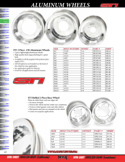
Materials used for Wheels on Rolling Stock
Katrin Mädler, Manfred Bannasch
Deutsche Bahn AG, Technical Centre, Brandenburg-Kirchmöser, GERMANY
1
Introduction
In the contact area between the wheel and the rail, the materials are used in those components encounter
the greatest demands. Not only is there the pure rolling motion under a constant normal and lateral load
to be carried, which leads to high shear stresses both on and beneath the surface of the respective parts.
Furthermore, relative motions between wheel and rail create slip in the contact zone, causing both
mechanical and thermal loading of the material. Consequently, the different characteristics of damage to
wheel treads and the running surfaces of rails can be described by a more or less pronounced combined
effect of adhesive wear, plastic deformation, rolling contact fatigue and thermal fatigue.
The presentation gives an overview of the usual concepts in material selection for rolling stock wheels
and the associated operational practice from the point of view of damage analysis. In addition, options are
presented for exploiting the full range of existing or new materials, without causing a detrimental increase
in wear on the rail, thereby putting the overall wheel-rail system at risk. To this end, results of
conventional operational tests and of specially developed rig testing are presented.
2
Wheel materials
As an appropriate response to known mechanisms of damage, the materials employed in wheels and
rails in Germany – as in the rest of Europe – were, and indeed still are, those steels whose predominantly
pearlitic structures containing hard cementite lamellae guarantee high resistance to wear. At the same
time a pearlitic microstructure, formed by transformation close to the point of equilibrium, ensures higher
resistance to transformation in operational use than, for instance, bainitic or martensitic structures.
Although UIC Leaflet 812-3 [1] for solid wheels lists seven types of steel, which mainly differ in carbon
content, heat treatment state and therefore strength, EN 13262 [2] contains only four types (Table 1).
Because Grade R1 for freight wagon wheels is on the decline in favor of the standard R7 material, and
Grades R2/R3 never established themselves in operational practice, this repres ents the current state of
technology in Europe.
R7 is by far the most commonly used grade. It is used for all freight wagon wheels and on most
passenger coaches. Where wheels made from R7 are intended for use in vehicles with tread brakes, the
fracture toughness requirements (KIC) must be fulfilled as well as the usual characteristic mechanical
values. Experience has shown that where carbon content exceeds 0.5%, the K IC values of 80MPa √m
called for in [1] and [2] can only be attained where comparatively small grain size (fine grain), high purity
and high homogeneity are present in the microstructure throughout the circumference of the wheel. This
of course places heavy demands on manufacturing quality. For this reason, these wheels are commonly
supplied with lower carbon contents (<0.5%C) which therefore puts them often in the lower strength
tolerance range, so that besides pearlite, large amounts of pre-eutectoid ferrite are present in the tread.
Although this leads to greater toughness, the wear resistance is correspondingly diminished. According to
Deutsche Bahn’s (DB) experience, a free (pre-eutectoid) ferrite content of ≤10% is advantageous in terms
of minimizing wheel wear at the tread.
For driven wheels on locomotives and motor coaches, R8 is increasingly the used grade. R9 is limited to
niche applications, e.g. permanent way construction vehicles and combined transport systems such as
the “Rolling Road”.
In summary, materials employed for solid wheels in Europe are largely restricted to unalloyed steels with
a maximum carbon content of 0.56% and – after appropriate heat treatment (fine pearlitization) of the
tread – tensile strengths of at least 820 to 980MPa in maximum.
How about the other part of the wheel-rail wear system?
At 0.6 – 0.8%, the carbon content of the European standard Grade 900A rail is higher than that of the
wheel materials. However, its maximum tensile strength is 1050N/mm², as this grade of rail is used in its
naturally hard condition, i.e. without subsequent fine pearlitization. Heat treatment of the railhead is
generally an option. Rails of this type are described as “head-hardened” and, to minimize wear in the
outer rail, are generally used only on track where the curve radius is <700m.
Steel category
UIC 812-3
EN 13262
Carbon
content
(%)
UIC/EN
Yield
strength
(N/mm²)
EN 13262
Tensile
strength
(N/mm²)
UIC/ EN
Elongation
Notch impact energy
(%)
UIC/ EN
(J)
R1 N
600...720
≤ 0.48
≥ 18
R2 N
700...840
≤ 0.58
≥ 14
R3 N
800...940
≤ 0.70
≥ 10
R6 T, E
ER6
780...900
≤ 0.48
≥ 500
≥ 15
R7 T, E
ER7
820...940
≤ 0.52
≥ 520
≥ 14
R8 T, E
ER8
860...980
≤ 0.56
≥ 540
≥ 13
R9 T, E
ER9
900...1050
≤ 0.60
≥ 580
≥ 12
N…normalized, T…rim heat treated, E…whole wheel heat treated
UIC 812-3
U-notch (RT)
≥ 15
≥ 10
≥ 10
≥ 15
≥ 15
≥ 15
≥ 10
EN 13262
V-notch (-20°C)
≥ 12
≥ 10
≥ 10
≥8
Table 1: Wheel steel requirements according to UIC 812-3 and EN 13262
3
Wheel tread damage – current situation
The demands placed on materials used for wheels and rails have grown with the introduction of highperformance rail traffic. The drive and braking performance of new locomotives and multiple units have
risen considerably and wheel-slide regulated traction controllers often operate at the limits of adhesion to
achieve continuous transmission of maximum tractive effort and performance. Moreover, increases in
speed and axle loading are a not insignificant factor. For instance, whereas the maximum speed of the
ICE 2 was 280km/h, it is now 330km/h for the ICE 3 – and there has been a simultaneous doubling of the
starting acceleration to 0.34m/s² with respect to the ICE 3’s predecessor. This has consequences for the
life of rolling stock. Whereas, 15 years ago, adhesion-related wear of the wheel profile was the major
cause of cost and material-intensive profile correction and even wheel exchange, the focus is now on
tread damage attributable to rolling contact fatigue, frequently combined with thermal fatigue because of
changes described before and the increasing switch from tread brakes to disc brakes in passenger
service.
Thus, for example, there are instances particularly on the driving wheels of modern vehicles on regional
and local routes, in which, after only a short time in service the wheel treads show signs of slip zone
formation. As a result of thermal fatigue these slip zones become micro-cracked and then, after further
service and increasing rolling contact fatigue, finally lead to spalling of damaged material (Figure 1a).
Results of metallographic investigations find that such damage is frequently initiated in those areas of the
wheel treads where, because of an intensive series of wheel-slide events, the material has been
transformed into martensite to a depth of several millimeters (Fig. 1b). This is often combined with local
tread collapse in the wheel [3].
However, martensitic transformation extending deep into the structure is not solely responsible for large
areas of flaking in the wheel tread. Occasionally, a wheel is found with severe damage virtually all around
its tread which is attributable solely to rolling contact fatigue – in other words, to material breakdown
resulting from repeated rolling under high vertical and horizontal loads. Above all, this affects vehicles
whose wheels are smaller (a higher number of revolutions) or whose wheelset loadings are higher
(greater vertical loads). In these cases, destructive examinations identify considerable plastic
deformations in the longitudinal and lateral directions. Moreover, the wheels examined to date have
predominantly been in the lower strength tolerance range.
a)
b)
Fig. 1: Wheel damage in diesel traction units
a) Cracks and spalling in the wheel tread, b) Microstructure in the cross-section
Where cracks resulting from rolling contact fatigue have their origins beneath the surface, these are due
to the superposition of the maximum sub-surface shear stress over local defects in the steel. Generally,
such cracks occur in disk-braked passenger coaches where speeds exceed 160km/h and are initiated by
hard non-metallic inclusions. For the DB these sub-surface initiated cracks do not represent a problem
because the wheel treads of all passenger coaches are subject to a regular ultrasonic check on
mechanized test rigs. Should a test of this type be missed however, catastrophic failure of the wheel can
result if the crack extends to the face of the tread and very large areas of the tread break away. Hence,
when qualifying new wheel manufacturers for DB, there is a special emphasis on their adherence to the
requirements for the degree of material purity.
Periodic out of roundness [3] is a problem that occurs in high-speed traffic, but also in vehicles that reach
200km/h. This is a regular occurrence of changes in radius distributed around the rim of the wheel. The
latest opinion is that higher order polygons (>5) are a consequence of local wear pro cesses caused by
dynamic effects – e.g. higher speeds combined with higher track stiffnesses – and lead to a rise in wheel
dynamics. Against this background, there is naturally the question of the extent to which a high material
quality (homogeneity) consistent all round the wheel rim, combined with higher wear resistance, can delay
the onset of out of roundness in the wheels.
Both spalling on the tread and wheel out of roundness cause vibrations in the vehicle body and thus have
a negative effect on ride comfort. At the same time they lead to heavier dynamic loadings on the vehicle
and track [4]. Furthermore, rail traffic noise increases considerably. Elaborate reprofiling of the wheel,
during which a considerable part of the wheel’s diameter is machined away, is necessary not only on the
damaged wheel but on several wheels of the affected vehicle for reasons of diameter matching. It is clear
that along with rising maintenance costs, this also brings a reduction in the life of the wheels to a level
that is sometimes not economically justifiable. In many cases “artificial” removal of material from the
wheel, by turning, is considerably greater than “natural” wear resulting from rolling contact in service.
Against this background there is also the recurring quest for materials capable of sustained resistance to
the increased loads. For this reason, Deutsche Bahn’s Technical Center has initiated and followed
through the testing of new wheel materials in recent years.
4
4.1
Testing of new wheel materials
Material concepts
For high-speed traffic, tests were conducted on a Japanese wheel steel that had already been in service
for some years in Shinkansen vehicles. In common with the UIC steels, the type in question is a non-alloy
steel; however its carbon content lies between 0.65 – 0.7% which is of a similar order to the usual steel
used for rails. Its tensile strength of 1050N/mm² makes this steel comparable with an R9 in the upper
tolerance range. Values for elongation, notched impact and fracture toughness not only meet the
requirements for R9 but surprisingly also – in spite of its higher carbon content – those for R7 and R8.
First and foremost this appears to be a result of the material’s high purity and its comparatively small
grain size. A further striking feature was the extreme homogeneity of the structure throughout the wheel
rim.
A range of material concepts were pursued for passenger services up to 160km/h. Particular emphasis
was given to the testing of bainitic Austempered Ductile Iron (ADI) for its suitability as a wheel material for
rail vehicles [5]. ADI exhibits a combination of high wear resistance and high fatigue strength with high
ductility when compared with other types of cast iron. An important “side-effect”: the graphite nodules
included in the cast iron microstructure act as a lubricant at the contact surface between the two friction
partners, thus reducing their wear. At the same time, the graphite inclusions bring about a damping effect
some three times greater than that of steel, which means that ADI wheels promise a decrease of rail
traffic noise. Material composition and heat treatment were matched together in such a way that tensile
strengths of about 1000N/mm² were achieved. Over the course of the project, wheels for testing purposes
were manufactured by a foundry and a wheelset manufacturer. Besides the usual laboratory testing for
assessment of material and manufacturing quality of the wheels, special attention was paid to the
evaluation of the ADI wheel in terms of fracture mechanics [6]. At the end it was found that the critical
crack size determined by means of fracture mechanics calculations can be safely and reliably diagnosed
by means of non-destructive testing procedures. Under DB’s routine maintenance procedures and testing
schedules ADI wheels would thus be deployable without problems.
A further emphasis was laid on the testing of wheel materials with improved resistance against thermal
loading. The types under consideration were two low-alloy steels – S2 and S3 – whose carbon content of
0.4 to 0.45% was somewhat lower by comparison with R7. Their strengths reach from the lower (S2) to
the upper tolerance limit for R7. The S2 fulfills the toughness requirements for R7, while the toughness of
the S3 corresponds to the lowest requirements of an R8. By the addition of alloying elements, the
tendency towards transformation of the pearlitic-ferritic microstructure into austenite is lowered. Under the
loads imposed by wheel-slide there should thus be a lower likelihood of brittle martensite forming in the
tread [7].
Before their planned service deployment, all these materials were subjected to a special test on the
wheel/rail system test rig in Kirchmöser. This not only tested whether the new wheel had a lower
tendency towards out of roundness and how it responded to the loads imposed by wheel-slide; rather, the
investigations centered on its influence on rail wear compared with the conventional R7 steel.
4.2
Rig testing
On the DB wheel-rail system test rig, rolling contact between wheel and rail is simulated at full-scale. It is
a wheel on roller test rig (Fig. 2). The full-size wheelset under investigation rolls on a driven rail roller
consisting of two rail tyres measuring approx. 2100mm in diameter formed from standard 900A grade rail
steel. The profiles of both the wheels and the rail tyres correspond to DB’s normal matched wear profiles.
The wheelset is mounted on a single-axle auxiliary rotary frame and can be loaded with axle loads of up
to 30 tonnes at speeds of up to 300km/h. Curving conditions with contact of the gauge corner at an
adjustable angle of attack, also like straight track conditions, can be controlled dynamically [8]. Loading
scenarios must approach the loads imposed on the wheelset during vehicle service as closely as
possible. They are based on the vehicle parameters and a combination of travel through curves and in a
straight line, varying speeds, braking maneuvers and weathering conditions. In order to achieve
reproducible results within short test time frames, critical service conditions such as tight curves and
emergency braking were emphasized out of normal proportion.
Initial results of longitudinal and cross-section measurements and of non-destructive crack testing of the
wheel tread are generally available after 6,000 – 8,000km, which corresponds to a test rig operating
duration of about four days. Testing can thus be carried out more economically and more quickly using
the test rig. Furthermore, only a trial on the wheel-rail system test rig enables an assessment of the extent
to which the new, more wear-resistant wheel material leads to greater wear on the rail. In tests on actual
track, these assertions can only be made with limited certainty.
Force/
displacement
cylinders
Wheelset
Driving
Rail roller
Fig. 2: Wheel-rail test rig, schematic
In the case of the wheel materials described at 4.1, the following results were achieved on the test rig
compared with the R7 wheel material.
4.2.1
Comparison of Shinkansen material with R7
Test conditions:
- Mean axle load: 13 tonnes
- Straight ahead and curving with radii R = 600 to 1,800m
- Speed: 110 - 190km/h
- No rail lubrication
- End of test run if lateral force >30kN and bearing acceleration >250m/s² as the limit for wheel out
of roundness
- Wheels were reprofiled between the first and second tests
Results:
31 500 km
Shinkansen steel
23 300 km
2nd test
1st test
10 000 km
R7 steel
9 500 km
0 km
20 000 km
It was found that the development of wheel
out of roundness is heavily dependent on
the material. In the first test run, the wheels
made of Shinkansen steel already
managed two and a half times the running
performance of the R7 wheels before the
appearance of comparable out of
roundness.
40 000 km
Running distance
Fig. 3: Running distances for getting wheels out of roundness
After the wheels had been reprofiled to a depth of approx. 2.5mm, the second test run with the
Shinkansen steel wheels was terminated after 31,500km, even though the limit values for lateral force
and bearing acceleration had not been reached compared to R7 wheels.
This confirmed the expectation that the steel with the higher carbon content and strength level exhibits a
better wear behaviour and that wheel out of roundness can be considerably delayed. One reason for this
appears to lie in the absence of free ferrite from the wheel tread.
After the test, only the R7 wheels showed small rolling contact fatigue cracks in the tread (“Tread
checks”).
In parallel with the wheel investigation, changes in profile to the head of the rails were recorded and
evaluated. In this way the potential for heavier damage to track due to the new wheel material can be
identified and assessed in a timely manner. The wear ratio of the wheel and rail was determined before
and after the test from the cross-section of the wheel tread and rail head and the ratio of the
circumferences of the wheel and rail tyres. This coefficient indicates the ratio in which wheel and rail
material are “consumed” on each rolling revolution, i.e. the extent to which a harder wheel causes greater
wear on the rail, and vice versa. Accordingly, a ratio of 1 means that the wheel and the rail wear to a
similar extent. In the previous case, a wheel-rail wear ratio of 0.86 was determined for the Shinkansen
steel. In other words there is a slight tendency for wear to be transferred more to the rail. It is not possible
to make a conclusive assessment at present for the wheelset fitted with R7 wheels because this value
was subject to far greater variability. Further test rig investigations should create clarity on this point.
4.2.2
Comparison of ADI with R7
Test conditions: as for Shinkansen steel/ R7
Results:
The wheels made from ADI material represent a special case within the test sequence: because of the
lubricating effect of the spheroidal graphite contained within the material structure which is released under
contact conditions at the wheel tread, the coefficient of friction was reduced and wear on the wheel and
rail considerably diminished as a result. Thus the wheelset on the test rig managed a running
performance in excess of 50,000km without reaching the termination criteria for either bearing
acceleration or lateral force. However, in moderation, it should be remarked that the lubricating effect on
actual rails in service would naturally drop to a lower level than that on the test rig whose rail tyres in
principle measure just 6.6m in length. After the test – by contrast with the R7 wheels – the ADI wheels
showed no signs of tread checks.
Both in the cross-section of the ADI wheel and the cross-section of the rail tyress there was virtually no
evidence of wear.
After the positive test rig results, trials were planned on double-deck coaches in regional passenger
service at speeds of up to 160km/h. However, during ultrasonic testing on the mechanized test rig, the
wheels manufactured for this purpose showed unpermitted indications in the wheel tread and web so that
the use of these wheels in service was abandoned.
4.2.3
Comparison of S2 and S3 with R7
Test conditions:
1. First test run:
Curving (6,000km) = check of tendency to out of roundness
- Mean axle load: 116kN
- Speed: 50 - 120km/h
- Curving with radii: 300 – 1,200m
- Effect of wet conditions
2. Second test run:
Straight line/braking (1,900km) = check of tendency to hardening under
demands imposed by wheel-slide
- Loads and speeds as above
- 3 x braking events from 200km/h to rest
- Hunting
- Effect of wet conditions
Loss of tread diameter (mm/ 1000 km)
Results:
After the first test run, both types of
steel exhibited greater wear in the
cross-section compared to the R7 as
well as a heavier loss of diameter
(Fig. 4). In addition, the wheels made
from S2 steel showed signs of
pronounced out of roundness –
evidently as a result of their
comparatively low strength and
higher free ferrite content in the
microstructure – whilst for the R7 and
S3,
out
of
roundness
was
comparable with the R7 wheels listed
in 4.2.1.
0,12
0,1
0,08
S2
0,06
S3
0,04
R7
0,02
0
Fig. 4: Wear behavior of S2, S3 and R7 wheels after first test run
After the second test run the wheels made from S2 and S3 steels with their higher resistance against
thermal loadings exhibited little wear, in line with expectations. However, the R7 wheels on this test
exhibited also little wear.
Because the rig tests with both the S2 and the S3 steels were unable to identify any improvement
compared with the conventional R7 steel, in-service testing with the more expensive wheels (due to
alloying elements) was not pursued.
4.3
In-service testing
(planned and not planned )
Running distance classes, Tkm
251-300
201-250
151-200
101-150
51-100
40
35
30
25
20
15
10
5
0
R7
Shinkansen
material
301-350
Running distance between reprofiling
1-50
Percentage of re-profiling events, %
Since 2003, 45 wheelsets with the Shinkansen wheel material have been under trial in ICE trailer
vehicles. The experience under this regime shows that, compared with wheels made from R7, these
wheels have required less frequent reprofiling. The relevant assessments for 16 wheelsets in each of the
wheel materials are presented in fig. 5.
Fig. 5: Running distances between
reprofiling of wheels made of R7 and
Shinkansen steel
It shows that because of unplanned events (profile deviations, out of roundness, tread damage, etc.) a
certain number of the R7 wheels required reprofiling long before they reached the ultrasonic test
scheduled for 240 Tkm, whilst the wheels made from Shinkansen steel largely reached this scheduled
test without intermediate reprofiling.
This confirms the results of the rig tests. To underpin this result statistically, a further large-scale trial is
planned.
5
Conclusions
With the introduction of high-performance rail traffic, the demands on wheel to rail contact have risen
once more. There is a link between this and the typical modes of wear in wheels which arise and limit the
wheels’ life. The wheel material employed and the manufacturing quality of the wheel have a considerable
influence on the formation of out of roundness and tread damage. To test new wheel materials for railway
service, both the usual laboratory tests and also elaborate in-service trials are carried out. The Deutsche
Bahn’s wheel-rail system test rig offers an opportunity for pre-testing wheelsets with new wheel materials
under real loading conditions. The tendency for wheel out of roundness and tread damage to occur can
be examined as can the question of wear on the rail.
Tests conducted in recent years have shown that the microstructure and the homogeneity of mechanical
properties around the wheel rim influence the occurrence of out of roundness. There are indeed
alternatives to those wheel materials that have been used hitherto. Furthermore, particular attention must
be paid to manufacturing quality, as the experiences with wheels made from Shinkansen steel and the
bainitic cast iron ADI have demonstrated.
References
[1]
[2]
[3]
[4]
[5]
[6]
[7]
[8]
UIC 812-3 Technical specification for the supply of rolled solid wheels of non alloy steel for
traction and rolling stock. 5th Issue. 01/1984
EN 13262 Railway applications – Wheelsets and bogies – Wheels: Product requirements. Issue
01/2006
Cassidy, P.: Non-periodic wheel out of roundness and microstructural inhomogeneity. Proc. of 6th
Int. Conf. on Contact Mechanics and Wear of Rail/ Wheel Systems, Gothenburg, Sweden, June
10-13, 2003, p.
Madeyski v., T.: Zusammenwirken Fahrzeug/ Fahrweg und Maßnahmen zur gegenseitigen
Senkung der Beanspruchung. ZEV + DET Glas. Ann. 122 (1998) 9/10, p. 613-619
Mädler, K.: Suitability of ADI as an alternative material for railcar wheels. http://www.ductile.org/
magazine/2000_2/railcar.htm
Kuna, M., Mädler, K., Hübner, P. and G. Pusch: Anwendung bruchmechanischer Konzepte bei
der Entwicklung von Eisenbahnrädern aus bainitischem Gusseisen. konstruieren & giessen 27
(2002) 3, S.
Poschmann, I. and C. Heermant: Werkstoffe für rollendes Eisenbahnmaterial. EI Eisenbahningenieur 53 (2002) 8, p. 47-51
Mädler, K., Ullrich, D. and M. Luke: Rolling Contact Phenomena at Wheels and Rails observed at
DB’S Full-Scale Simulation Test Rig. Proc. of 6th International Conference on Contact Mechanics
and Wear of Rail/Wheel Systems (CM2003) in Gothenburg, Sweden June 10–13, 2003, p. 17-21


© Copyright 2026