
Document 123489
WAR DEPARTMENT
MAINTENANCE MANUAL
AND PARTS CATALOG
TRAILER, DUMP, 2 WHEEL
1/2 TON, AIRBORNE.
CONVERT0 MANUFACTURING CO.
PITTSBURGH, PA. & CAMBRIDGE CITY, IND.
MAY 31, 1943
COMBINED
MAINTENANCE MANUAL
and
TMS 9084
PARTS CATALOG
WAR DEPARTMENT
TM5.9084,Maintenance Manual and Parts Catalog,
Trailer, Dump, 2 Wheel, Airborne, ~ublishedby the
Converto Manufacturing Company, Is furnished for
the information and guidance of all concerned.
TRAILER, DUMP, 2 WHEEL
l/t T O N , A I R B O R N E
Manafactzcred for
(AG 062.11 (4/26/41) PC (C), June 10, 1941.)
G.C MARSWALL,
Chief of Staff.
Official:
J. A. ULIIO,
Major General,
The Adjutant Genera
'THIS BOOK COVERS:
PURCBASE
ORDER Nos.
U.S.A. REGISTRATION Nos.
INDEX
OPERATIONS SECTION
CoupIing the Trailer...................................
Description of EqGpment...............................
FOREWORD
t
This vehicle is designed to save time and labor. Its general
usages may be described briefly as fitting into two classes. (1) General cargo work such as requires the use of a small trailer, and (2) a
trailer that will dump, for particular use in moving earth, soil and
other matters that can more easily be unloaded by dumping*
..
What lt 1s-----------------------------------+----What it comprises................................
Dimensions of the Railer--------------------------------
Page
--
Dumping the Trailer
----------Lighting the Trailer
Lubrication Chart ---------------I-------.
-----Operating the Stanchion......................
-----Operating the Tailgate--------------------------- ------Preparing the Trailer for Storage........................
Rigging Points of the Trailer...........................
Using the Trailer
The proper use of this trailer will save valuable man hours. It
has been thoroughly inspected, and like any other piece of equipment,
t o maintain it in proper operating condition, common sense should
be used in handIing the equipment. It should not be overloaded.
----------------------I-----------------
MAINTENANCE SECTION
Axle Assembly ........................................
Replacing the Axle.................................
Body Assembly ---------------------------------------Dump Release Assembly .................................
Frame Assembly
Lunette Eye Assembly..................................
Stanchion Assembly ....................................
Tailgate Apparatus ....................................
Theel Assembly
Care and Inspection of Tires-----------------------Removins Tires from Wheel ----------Removing Wheel from R u b----------------I--------RepIacement o f Studs---- ..........................
Wheel Bearings
-----------I---------------------------
PURPOSE
-------------A
In the following pages we have described how to take care of this
unit and handle it in such a way that it will give maximum swvice
and dependable performance. These instructions are pubIished for the
information and guidance of those units or individuals hax-ing charge
of the operation, maintenance and repair of this equipment. They
include descriptions of the trailer, as well as instructions for its operation, inspection and maintenance.
.
-------I---------------
SPARE PARTS SE2TION
Instructions for Ordering-------------------------------Numerical Parts List---------------------------------Spare Parts AssembIies
Dump Release Assembly..........................
Lunette Eye Assembly..............................
Stanchion Assembly
Wheel Assembly ...................................
Axle Assembly
Tailgate Trip Assembly --------------------------Tailgate Lock Assembly ..........................
Tailgate Assembly
MiscelIaneous ......................................
-----------------------------------A-
15
21
16
IT
I7
18
19
20
20
19
17
PART I
OPERATOR'S MANUAL
OPERATORFSMANUAL
1
OPERATOR'S MANUAL
OPERATOR'S MANUAL
2
DESCRIPTION OF EQUIPMENT
The CONVERT0 Dump Trailer
What it is:-A two wheeled pneumatic-tired, I,$ hn, a11 steel
trailer f o r both general cargo and dumping duties.
What it comprises:-Its components, 9 sub-assembIies.
L
3
to the frame. A hole in the tailgab permits the attachment of a
nozzle and the ultimate distribution of Uquids (from their own container) carried in the trailer. When not used for this purpose, a
cover plate (Illustration 3, E) is attached to the rear of the tailgate
as are slots far holding the cover plate.
When the trailer is to be used for dumpjng, the permanent body
lock (Illustration 2, H) should be released. This is an added safety
lock. It can be released by unscrewing the Permanent Body Lock
Thumb Nut until the Permanent Body Lock Bolt clears the Permanent Hold Down Strike. (Illustration 2, C).
1. Frame Assembly
Wheel and Axle Assembly
2.
3.
4.
5.
6.
7.
8.
9.
Stanchion Assembly
Lunette Eye Assembly
Body Assembly
Dump Release Assembly
TaiIgate Assembly
Tailgate Trip Assembly
Tailgate Lock Assembly
C o ~ p l i n gthe Trailer
Due care should be exercised when coupling or uncoupling the
trailer so that it will not get out of control.
A rope (not furnished) should be run through the hole at the
(Illustration 2). This rope shouId be long enough to
top of "A" & 'WB"
reach the motivating vehicle. It is for convenience in dumping the
trailer and in operating the tailgate.
To couple-up the trailer t o a jeep, lift up the pintle hook lock,
and raise the latch of the jeep. Raise the tongue of the trailer and
place the Lunette Eye IIllustration 1, C) in the hook. Close the pintle
hook and be sure that the lock is down in place.
Ofisrating the Stanchion
After the trailer has been coupIed to the jeep or truck, pull out
the Stanchion "T Pin" (Illustration 4, E, Page 7) and raise the
Stanchion (Illustration I, 30) to a parallel position with the tongue
of the trailer. The Stanchion "T Pin" will automatically be drawn
back to position when the proper position is reached. Before uncoupIing trailer, pull Stanchion "T Pin" and lower the Stanchion to a
90 degree angIe to the tongue of the trailer. As soon as this position
is reached, release Stanchion "T Pin" and it wilI lock ir. place.
Using the Trailer
When using the trailer for cargo work, the permanent body lock
(Illustration 2, C: and H) should be fastened. This acts as a safety
catch to make certain that the body will remain in a parallel position
Dumfii~tgthe Trnilar
The trailer is dumped by activating the dump release assembly.
This is accernpIished by pulling the dump reIease assembly lever forward. You may do this either by puIling the lever fomvard manually
or by manually pulling a rope attached at "E" (Illustration 2). This
releases the body dumping catch shown a t "G" (Illustration 2). To
bring the body back to its original position, pull down on the front
of the body bin untiI it is in a horizontal position and the plunger
rests on the strike.
4
OPERATOR'S MANUAL
OPERATOR'S MANUAL
5
the Tailgofe
The tailgate ipl opened by activating the Tailgate Trip AaaembIy.
This is accomplished by pulling the Tailgate Trip AssembIy Handle
forward. You may do this by either pulling the handle forward
manually or by manually pulling the rope attached at A (Illustra
tion 2 ) . When the tailgate is closed, it is automaticaIly locked in
place at the tailgate catch (Illustration 3, B),
Opesafing
LUBRICATION POINTS
(See Lubrication Chart Next Page]
OPERATOR'S MANUAL
OPERATORS MANUAL
6
L#bricat%'olzChart
Illu~
trah
/
I
Port to Ba
hbhted
-
5000 Miles or Every 6 Mos.
Wheel Bearings
5
I
Lunetta Eye
6
WB-2Grease, Wheel
&axing No. 2
-
CG-1, General Purpose
Grease No. 1 or 0
ZOO0 MIlea or Monthly
Awembly
\
-
Tailgate Trip
8
h b & ~ ~ nItn t ~ v f i l
Handle
10
II
11
1 Hinge
Pivot Pin
11(100Milea or Monthly
1000 Miles or Monthly
I
Stanchin AasemMy 1000 Miles or Monthly
Axis
OE30, Oil, Eagine,
SAE 30 above 32" F.
Body Dumping
A~sernbly
mRE PRESSURE
- - -
\
OE10, Oil. Engine,
SAE 10, below 52" F.
35 Lbs.
Lighting the Trailer ( B y Reflector)
A K-D Reflector (Illustration 3, D), is on the taiIgate of the
CONVERT0 DUMP TRAILER.
Dimensions of the Trailer
Weight -------------------------4-636
pounds
Length ,------------- ------- - - - - 9334 inch@&
Height
451,4 inches
Width
56 inches
Preparing the Trtiilsr for Storage
Jack up trailer and remove tires from wheels. Keep tires in a
cool dark room. Since painting is a. preservative, the only parts that
need additional treatment are the unpainted materiais on the trailer.
These should be treated with a few drops of oil or a thin film of
grease. Particularly is this important in the following: Bearings and
plunger in the body dump release mechanism, the spring plunger in
the lunette eye assembly, and the bearing blocks in the tailgate release
assembly.
Rigging Poi~ttsWhen Transporting the Trailer
(When not crated)
Draw a rope through the Lunette Eye (Tllustration 1, C) and
fasten securely t o the flow. Then draw a rope through the holes in
each skid plate (Illustration 3, R) ; and fasten swnrely t o the floor.
ILLUSTRATION 4
7
PART I1
MAINTENANCE MANUAL
MAINTENANCE MANUAL
9
1. The Frame Assembly
THE FRAME--is an all steel construction and consists principally of two 3 inch channels, parallely placed, with a front lateral tie
of 3 inch channel and a rear lateral tie of 2 inch channel, reinforced
with 11 gauge vertical gusset braces. Due to its rugged design and
materials, the frame normally should require very little attention.
Vehicles which have been in an accident of any serious nature which
may result in sprung pads should be carefully checked for proper
alignment t o avoid tire wear, Excessive tire wear or the swaying
of the trailer may indicate a sprung or misaligned frame. The most
convenient way to cchck alignment is t o turn the trailer bottom side
up and checking should be done from the front of each frame siderail and also from the ,rear end. The tongue should also be checked
a t the same time.
If the Permanent Body Lock
be knocked off, a
1)
new one can be
welded into place.
PERMANENT HOLD DOWN LOCK
It is also a simple matter to renlace the Permanent Body Lock Bolt or Permanent Body Lock Thumb
hut, in the event they are lost or broken.
A Zerk Fitting is on the front end of the frame (Illustration 6).
It should be lubricated with a Zerk Gun every 1000 miles or monthly.
Use CG1, General Purpose Grease, No. 1 or 0 f o r lubrication.
2. Wheel and Axle Assembly
v
A. WHEEL ASSEMBLY
Removing Tires from the Wheel
First, let the air escape fmm the tire by
removing the valve stem core. Then insert;
the tire tool in the slot of the rim and pry
d a m while tapping the opposite side of the
rim with a hammer. When reinstalling the
tire, inflate the tire before instaIIing and
make sure that the bead lock ring (Illustration 12) is properly fitted into the
la
MAINTENANCE MANUAL
MAINTENANCE MANUAL
Care and Imsfiectfon of Tires
It ia recommended that an air preasure of 36 pounds be maintained on these tires. The pressure should be checked every 500
miles or every 5 days. Wheels should be checked to insure they are
running true, and that all stud nuts are tight.
test whether adjustment is necesessary or not: (1) raise the trailer
Removing Whesk from Hub
Lower stanchion to support the front end of the trailer.
place blocks under front and rear of opposite wheels. Then
the stud nuts (Illustration I, E), about a quarter of a turn.
jack under axle and elevate. Remove atud nuts and pull off
Next,
looaen
Place
wheel.
Re#lacement of Worn w Broken Studs
First, remove the wheel from the hub. Next, remove jam nut
from the atud which is to be replaced. (Jam nuts are located on the
back side of the hub), Then using a l/z inch punch, drive out the stud
or studs, driving from the back side. Finally place new stud in position with the shoulder placed so that it will fit into the groove in the
hub as it is driven into position,
Caution: Studa marked "L" should be used only on the left wheel
which is on the left side of the traiIer when the observer stands facing
the direction of travel, Studs marked "R" should be used only on
the right wheel. If studs are used on wrong wheel, the nuts will work
loose and wear out or break the studs, and the wheel will come off.
Wheel Bearings
The wheels are m i e d on two opposed tapered rolier bearings.
Bearings are adjustable for wear and their satisfactory operation and
long life depends upon periodic attention and carrect lubrication. To
a
dI'
with a jack ao that tires clear the floor. (2) With hands, test the sidewise shake of the wheel. If bearings are adjusted too loose, the shake
of the wheel will be perceptible. If bearing adjustment is too tight,
the bearings will bind and the roIIers may break or become overheated.
T o adjust: I. With wheels still on jack, remove hub cap,
2. Tighten adjusting nut until wheel binds, at the
same time rotating the wheel to make sure all
bearing surfaces are in proper contact.
3. Then back off nut about I J 6 turn or more if necessary, making sure wheeI rotates freely.
4. Replace locknut.
5. When hub is completely assembled, test wheel
shake before removing jack.
When replacing hubs, the hubs with the right hand threaded
studs are placed on the right hand side. Those with the left hand
thread, on the Ieft side.
I t is recommended that every 5,000 miles, or every six months,
the wheels be removed and cleaned, the bearings repacked with new
grease (WB2, wheel bearing grease). If the grease seals are damaged
or the bearings or bearing cups are pitted, they should be replaced.
B. AXLE ASSEMBLY
If the trailer "whips" or the tires become excessiveIy worn or
scuffed on the inside or outside of the trailer, the difficulty may be
due to a loose wheel, shifting of load, or a bent axle. First, check to
see that the load is properly distributed. Then cheek the stud nuts
on both wheels to see that they are tight and that both tires are inflated to the correct pressure of 35 pounds. If the whipping persists
after checking the above features, then the trouble may be due t o a
sprung axle. Inasmuch as the axIe cannot be straightened except in
a well equipped shop with a power press, if this occurs in the field,
it is best to replace the axle.
.
---12
21262-50003R E
2 1263-5000-3L Bo
5000-6
5 0 0 0 4 R 26949 Hub andstud Asaembly
SOOWL, 27000 Huband Stud Assembly
VICTOR 62054
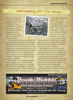
DIAGRAM OF THE TRAILER WHEEL
Bearings
11
-
Axle
-
-
MAINTENANCE MANUAL
MAINTENANCE MANUAL
Replacing the Axle
Lower stanchion t o support the front end of the trailer. Solidly
jack up the body at the rear. Next, take off the wheels. Loosen bolts
and nuts (Illustration 3, M) This will free the axle from the frame.
To install a new axle, reverse procedure.
Strike (Illustration 2, GI, or Body Skid Plates (Illustration 3, F) are
knocked off, new ones should be welded into place. Oeher abutments
pertaining t o Tailgate Lock and the Tailgate Trip Assembly will be
treated under the heading of "Tailgate Apparatus."
3. The Stanchion Assembly
Refer to IIIustration below to get a complete view of each of the
parta and their functions, also their proper positions and how to replace them. It is hardly likely that any replacements win be necessary
with the exception of the trip handle or spring. The handle is replaced by pulling out cotter pins (Illustration 4, J and K ) . This will
release bolts and the body trip handle is then easily extracted. To
install, reverse procedure. The spring is replaced by removing nut
14600-26) taking off washer (4600-27), then, removing the Plunger
Housing Cap (4600-10). and taking off washer (4600-6). Then pull
out spring, To install, reverse procedure. This assembIy should be
oiIed every 1000 mites or monthly with the type of lubricant as epecified in the lubrication chart on Page 6.
12
.
"
T
- *
.
,*". -
10 Stanchion kmembly ( I )
4 8 6 1 0 Waaher (I)
Spring (1)
':
1 6800-11
Pin (I)-
'----
48w-1
.
\-,
on
1
4ssembty
The stanchion ia easily replaceable. To do this, jack up
frame, remove cotter pin attaehed to reverse side of bolt
at (lllnstration 4, F). Then
r e m o v e castellated nut and
pull bolt out. Next, pull out
cotter key on opposite side of
"T Pin" (Illustration 4, E).
This will permit the "T Pin"
to be withdrawn and the stanchion leg can then be puIled
out. To install, reverse procedure. Oil every 1000 miles
with engine oil as specified in
lubrication chart, page 6.
13
6. Dtxmp Release Assern bl y
Housing (
100 Dump Release ( '
.1
: ("
-
,
.
4. The Lulzette Eye Assembly
The Lunette Eye is of a swivel type which relieves much strain
on the Jeep and Trailer. To remove Lunette Eye, pull out cotter pin
(Illustration 4, G ) then unscrew nut, PuII off washers and spring and
then pull out Lunette Eye. To install, reverse procedure. There is a
Zerk Fitting on the Lunette Bearing Block which is attached to the
frame. Grease every 1000 miles or monthly with CG Grease 1 or 0,
as specified in Lubrication Chart, Page 6. (See also Illustration 6,
Page 5.)
"
.* .-
""
.
%
.
A
>
A
*
*-,<*
A7,M Lunette Eye AssembIy
?..,
" - "
" . " ..
A
4LocGa
'
"
-'
.
mette
E&' (1)
-,
-3 Spring
-:
1 0 4 Nut 1
3 8 0\ h
m
2 Cotter (1)-
* 0
-/.
:3 Cotter A(l)-$600_7 Washer
4600-6 washer /lJ--'w
i0&21
h
{l)/"O
U
8
r
-4600- S P ~ ~ W
1 Nut {If
(1) 0"460&26
Washer
,.
a
'
O
O
O
C
Q
C
.I7Nut 14+
18 Bolt ,I41
18 Nut (4)
p Release Agser
J -
7. The Tailgate Apparatus
5. The Body Assembly
THE BODY-is of a11 steel construction, welded into one unit.
A minor dent in it can be hammered or pounded out. To remove the
body from the frame, pull out "T Pins" (Illustration 4, L) and devate
body from the frame.
In case such abutments as the Tail Gate Hinges (IIlustration 3,
A ) , Permanent Hold Down Strike (fllustration 2, C), Dump Release
To remove tailgate, remove cotter pin at "F'? (Illustration 3).
Then pull out pins. Lift out the tailgate. To install, reverse procedure. To replace the tailgate reflector (IUustration 3, D) insert
chisel and knock off. To replace, spotweld new reflector in place.
To replace the tailgate- catch castings, drive out pins (Illustration 3, HI. Release Spring Attachment and pull off. In replacing
these castings, make certain that the left hiIgate catch casting is
put on the Ieft side of the trailer, and the right tailgate catch casting
MAINTENANCE MANUAL
14
-9 Cotter (2
rip Awmbl
C.
I
.
5 2 0 0 4< ;
U'*52~7
Spring
PART 111
i 3 0 M Rod ( 1 ) ~
. .Spring
/ 11)
5200-7
- \
-2 Lock
tn
(1, 5300-7
(
1
@*530&7A Cap
Platc (I) 5 3 0 b 8 Screw (I) . 530D-6
a
- .
@
(ITI.
hl--i,.+k
Fin (2)
.
.
TAILGATE TRIP AND TAILGATE: M C K ASSEMBLY
is put on the .right aide of the trailer. A few drops of oil en the moving
parts (Castings) every 1000 miles or monthIy, as specified in t h e
lubrication chart on Page 6, will assist greatly in the operation. To
replace spring found under apring cover plate (Illustration 3, J) unscrew P.K. screw at top of cover plate, remove outer cap, and replace
with new spring.
The tailgate trip rod can be replaced by removing the cotter pin
(Illustration 3, N) and then releasing spring (Illustration 3, G ) .
To replace the tailgate trip handIe, pull out cotter pin (Illustration 4, M) then unscrew nuts (Illustration 4, N). This will release
bolts and the lever can then be extracted. A few drops of oil at the
base of the tailgate trip handle Flllustration 8, Page 5) every 1000
miles or monthly will greatly assist in operation. Use lubricant shown
in Lubrication Chart on Page 6.
--
lector (I)
.
5 1 1 0 4 2 Himige (2)
5100-25 Cotkr f2)
Tail,gate Assem
SPARE PARTS
PREPARATION OF REQUISITIONS
SAMPLE COPY FOR PISE IN THE
PREPARATION OF REQUISITIONS
SPARE PARTS SECTION
15
PREPARATION OF REQUISITIONS
State PERIOD de4pnatmn by usc or onc QI
thc tolfewlng t c m :
(1) "lMTIAL1* hnt rqukitbn of author.
lzrd allowances.
(2) "REPLENISHMENT" subxqucnt tc.
qulsrtrons to maintain a u t h o r i d allow.
unce
(3) "SPECIAL" rtquisitions for nnrrnsary
rwin nor covered by a l l w a n m .
-
I
Enacigmc) fquisirmru wnt by ttltphanr.
tclcgrapli, or mdro must always be Fonfirmd
immcd~adywith r q u i a l t m markrd: "Confimirtg (state idcntifpng detn)"
-
-
Prcpart a srparatc
rquisiticn for tach
diFtcrcnt msfhint,
\
Typc4'SPAREPARTS"
A sample requisition in the correct form for submission by the
Engineer Property Officer is shown on the oppusite page.
in u p p r right hand ma.
net 01 ~ q u i s i t i mlomi.
THIS SHALL BE FOLLOWED IN MAKING
OUT REQUISITIONS
1
SDARE
PARTS
In order to eliminate duplication of work, Property Officers may
authorize organizations to prepare requisitions in final form, leaving
requisition number space hlank for completion by Property Officer.
THE FOLLOWING RULES WILL BE OBSERVEI)
CAREFULLY IN PREPARING REQUISITIONS
FOR SPARE PARTS:
Col., C. E.,
E x e e u t l + s dfflesr
Vajor, C.E..
cnglneer fropertg Office>.
a.
b.
c.
46C10-2
460ol3
4600-6
-
YOKE
em
HLNDtB. M y TAp
M
'ASHW,
Pluugsr Bolt
COUVWTO LUII!TTB l$lfi
d.
e.
01
ASsmaLy
47-1
EYE, h a f t s
nu
4700-3
SPRTII'G. COEpF13lS10n
em
f.
g.
CONVEXTO STMCBICH ASSEBLY
01
W-
h.
ea
i.
j.
Prepme a separate requisition for each different machine.
Type "SPARE PARTS" in upper right hand corner of requisition
form.
State PERIOD designation by use of one of the following terms:
(I) "INITIAL"-first requisition of authorized allowances.
(2) "REPLENISHMENTu-subsequent requisitions to maintain authorized allouTances.
(3) "SPECIAL" - requisitions for necessary repairs not covered by allowances.
Give compIete shipping instructions.
State proper nomenclatme of machine, and make, model, serial
number and registration number.
State basis or authority, and date delivery is required, immediately below description of machine.
Group parts required under group headings as shown in manufacturers' parts catalogs.
State manufacturers>arts numbers and nomenclature descrip
tions accurately and completely. Do not use abbreviations.
Double space between items.
Emergency requisitions sent by telephone, telegraph, or radio
must always be confirmed.immediateIy with requisition marked :
"Confirming (state identifying data)
Nonexpendable items such as tools must be accounted for, when
requisitioned, by a statement that they have been placed on REPORT OF SURTQY or STATEMENT OF CHARGES.
".
k.
I8
SPARE PARm SECTION
I
WARE PARTS SECTION
19
SPARE PARTS SECTION
SPARE PARTS SECTION
21
Converto Manufacturing Co. manufacture practically all parts. However,
when another manufacturer's parts are or can be ueed, his initials and part nnmher
foIlow description of the item. The names and addresses of these manufacturers
are :. .
K-D Lamp Company ------------------------------------------C~nc~nnati,
Ohio
Kelsey Hayes WhceI Company.................................
DetroiG Michigan
Tirnken RolIer Bearing Company .............................
Detroit, Michigan
Victor Manufacturing and Gasket Company-,-,----------Chicago, Illinois
ALL PRICES SHOWN ARE F. 0. B. CAMBRIDGE CITY, INDIANA, ANT)
ARE SUBJECT TO CHANGE WITHOUT NOTICE.
(A slight additionaI charge to cover cost of packing wiIl be added.)
No.
Part
Number
Req'd
Description
Page
Weight
Lbs.
Prke
DUMP RELEASE ASSEMBLY
STRIKE, Bolt
-------------------
YOKE
1
1
HANDLE, Body R i p------------- 1
GUIDE, Trip Handle ----------__----1
BOLT, Rold Down Plunger--------- 1
WASHER, Plunger Bolt, T i " USS
1
WASHER, Plunger Housing End
16
36
16
16
16
16
Leather, 99" ------------------SPRING, Plunger ---------------HOUSIYG, PIunger --------------CAP, Plunger Housing-----------CLAMP, Bolt Housing
1
16
1
16
1
16
I
16
2
16
HOUSING, Hanger ---,---------1
16
BOLTS & NUTS, Top %"xl"SAE 4
16
BOLTS & NUTS, Bottom, a/sW x 1%"
S.4E ..........................
4
16
LOCKWASHER, 4g" USS--------- 8
16
PIN, RandIe .....................
1
16
PIN, Handle Pivot--------------- .. X
16
KEY, Handle Cotter--------------- 1
I6
KEY, Handle Pivot Pin Cotter, '/a''
x I" -------------------------1
16
WASHER, HandIe Pivot Pin. I/a"
SAE
1
16
NUT, Rex Jamb, 7/16" USS------- 1.
16
LOCKWASHER, 7/16'' USS ------- 1
16
SPACER, Yoke Washer, %" Std.--4
16
WASHER, Handle Pin, a/,'' Std
2
16
------------+
----------------------I---
.----
4700-1
4700-2
4700-3
4700-d
4700-6
4700-7
LUNETTE EYE ASSEJiECY
LUNETTE EYE
1
WASHER, Lunette E y e Bearing,
74" SPLE.......................
I
SPRING,Compression
1
LOCK WASHER, 1/8" SAE-------- 2
1
N U T Castellated, G" SAE-------KEY, Cotter, I/s" x 1%"----------- 1
17
13.25
I7
I7
17
.06
27
-50
-0625
-1875
17
-0313
12.00
-06
'50
.la
.I6
-01
22
SPARE PARTS SECTION
SPARE PARTS SECTION
No.
Req3d
Page
Weight
Lbs.
Pwt
Nqtmbtw
STANCHION ASSEMBLY
-------I--------
FRAME ASSEMBLY
ZERK FITTING, Lunette Eye_---ANGLE, Permanent h d y Lock---4900-15 BOLT, Permanent M y Lock-----,
4900-21 NUT. Permanent B o d y Lock Thumb,
K" USS -49W-22 LOCKWASHER, 5
'' U8S --------4900-26 KEY, Permanent Body Lock Cotter,
C/s" X a/qw
4900-25
PIN, Axis Pivot
4900-251 PIN, Cotter, 3/16" r 1%" --------4900-2SB CHAIN, Axis Pivot Pin
17
17
17
.OI
17
15'
.09
.02
17
.Ol
17
17
17
1.
-005
-01
6.00 x 16
6-00 x 1 6
5000-1
WHEEL (Complete Assembly)--- W H R E L, with Nuts and Ring
Page
Lbs.
~&oht
Price
TIRE, 6-Ply.M a d and Snow Grip--TUBE. Heavy Duty (with Sehradw
Valve)
2
Not Ill.
2
Not 111.
11.22
26
2.5
1.41
BODY ASSEMBLY
----------------
2
KEY, TaiIgate Hinge Cotter-------
2
17
1
20
3
20
20
20
5100-12
HINGE. Tailgate
5100-13
PINS. Tailgate H h g e------------,
2
17
,006
-015
17
-25
-06
STRIKE,Permanent Body Lock.---. I
NAME PLATE ----------,------1
17
.621
-75
5100-16
5100-IT
5100-25
,375
17
-625
.805
.22
,005
TRIP ASSEMBLY
.I9
HANDLE, Tailgate
Trip ----------
BOLTmHandle Pivot--------------1
20
PIN. Link Pivot-----,--X
20
LINK
1
20
WID, Trip
1
20
NUTS, Trip Rad, +$n USS
2
20
SPRING --------,,,-2 --20 ---,,-,
-L---------,-,-------------
WASHER, Trip R d , %" CTSS ----KEY, Cotter. I/aKx 5"-----------SUTB, Handle Pivot Bolt----------
WHEEL ASSEMBLY
5000
No.
TIRES AND TUBES
17
3.385
CASE, Stanchion ----------,-,--8.44
FOOT, Stanchion
17
17
-22
BOLT, Stanchion --------,-------.OP4
17
M'ASRER, Spring Rolt, 5'' Std.---.048
17
SPRING,Compressicm ---- -------.33
BOLT, Pivot, fin' x 4"-----------17
17
-03
NUT, CastIe Pivot Bolt, 5'' USS--.0055
KEY, Cutter, 'Js" x 1%"----------17
4900-7
4900-14
Req'd
DssePiptkn
23
1
Not III.
73
28.4
-0.5
-025
.025
IS
KH25692
2
5000-2
NUTS, Wheel KH25779
16
IS
5000-3NL NUT. Lug Bolt, Left KfE24576----- 5
1R
5000-3NR NUT, I,ng Bolt, Right KA24575---,
5
18
.a25
5000-3R BOI,'PS, Lug, Right KH21262-----5
18
-025
5000-SL BOLTS, Lug, Left KHz1263------- 5
1s
5000-4L ASSEMBLY Hub with Cups, Left
6.75
I8
KH27000
1
5000-4R ASSEMBLY Hub with Cups, Right
1s
6.15
KHz6999
1
5000-4A C U P. Wheel. Inner and Outer
2.00
RH18520 ---------------------- 4
18
.I8
18
5000-5
RETAINER Grease Vict 62054,--2
BEARING, wheel, Inner and Outer
18
1.68
TI51 18590 -----------------,--.
.055
LOCK WASHER, JV heel----------18
.25
18
NUT, Axle -------,-------------1.00
18
CAP, Hnb Wlllys A-6038---------1s
.45
CAPSCREW. %" x 7/g" SAE
ASSEMBLY, Axle, with Pad and
27.5
Clamp
19
-25
BOLT, Axle Clamp, 9/16" SAE---19
4.5
19
KING, Bead Lock AH25930-------LOCKWASHER, Axle Clamp, 9/16''
19
-0625
SAE ----------+--,,-----*---1250
19
NUTS, Axle Clamp. 9/16" SAIL---------+----
I-----
----------------I-------
5300-1
5300-2
5300-4
5300-7
5300-1A
5300-6
5300-8
1
2
LOCK ASSEMBLY
1
LOCK, Tailgate RE.,------,--,,
20
1.5
1
20
1.19
LOCK, Tailgate L.H.,-----,-------1
20
5.1 3
ROD, Connecting
1
20
-625
PLATE, Spring Cover---,--------1
20
.I1
CAP, Spring Cover-----------,,--01565
PIN, h k .......................
2
20
1
20
.01
SCREW, Spring Cover Cap
+
,,,
-95
.SO
.95
.I5
-07
.006
.a3
TAILGATE ASSEMBLY
5400-1
TAILGATE Assembly
5400-4
5400-5
BOLT,Hinge
5100-6
5.100-10
5400-11
------------
1
I9
46.117
8.80
I9
-313
.05
WASHER, Hinge Bolt, 5" USS--2
I9
.03125
.01
1
19
1.06
.I2
YI,ATE, Hole Cover-----,--------2
16
.25
-10
BOLT. Laek
19
-375
-75
REFLECTOR, Red KDS 333------- 1
2
CONVERT0 CATALOG
TM5-9084 CATALOG ----------------Weather Proof Envelope ---------------------------.-. -
Reproduced by. and sold by Portrayal Press.
P.O. Box 1190. Andover. N. J. 07827 USA
.46
.05
Sirice Manual TM5-9018 was published, two additional procurements for the Converto Trailer, Dump,
Towed-Tne, %Wheel, I,$ Ton, (Airborne) have been placed with this company. They are : . -
Furchase Order No.
U. S. A. Registration Nos.
In order to increase the efficiency and to augment the already large amount of uses of this trailer, a number
of changes have been made in the trailer, and all were incorporated in those trailers carrying the above registration numbers.
T h e changes (by assemblies) are :
4600 (DUMP RELEASE)
The leather washer (4600-7) has been eliminated entirely. The clamps (460b13): bolts and nuts (460017); bolts and nuts (4600-18) have been eliminated. In their stead, two U-bolts (460050) now hold the plunger
housing in place. Four nuts (4600-31)screw onto the U-Mts.
4700 ( L U N E m
EYE ASSEMBLY)
On registration numbers 0876861-0880860, a heavier lunette eye ia furnished. It i s to be noted, however,
that the heavier lunette eye is still interchangeable with lunettes furnished on other trailera.
The T Pin (4800-61, the spring (4800-l f ) , the: washer (4800-10) and the cotter key (4800-14) have been
eliminated. A e chion rtpring bolt (4800-16) is now u a d in their stead. To place the stanchion in a perpendicular position the frame of the trailer, pull out stanchion spring bolt until stanchion drops to the perpendicular position, Then place the spring bolt back in +ition. This d l Tmk the atanchion in the perpendicular
position. Te raise stanchion for use in motion, pull out stanchion spring bolt and raise stanchion to a paralIe1
position to the tongue of the trailer. Replace spring bolt.
%
5000 WHEEL AND AXLE ASSEMBLYI
Etich wheel has been reinforced with a reinfoxing disc welded both on the outside and inside of the
wheel. 'Shb is to add strength to the wheel and eliminate any haring action. The axle now hss rr m
e seal p m
tectar (50WZO) welded onto it at both ends. This is to prevent any dirt from entering the wheel assembly.
In addition to the above, an outer wheel bearing washer (5000-193 haa h e n add& to this amembly. This b
placed on the wheel immediately after the bearing.
An amber reflector (5100-35) has been added. The pin (6100-X8) holding the tailgate to the taiImte mount
has been diminat&, and in its stead, an eye boIt (5100-n) has
added.
5240 and 5300 (TAILGATE LOCK AND TRIP ASSEMBLY)
The spring (5200-7) has been eliminated and in ib place, a longer spring (S200-14) la now used. Tailgate
lock Mi,right hand (5300-1) and tablgatcr lock, lei t hand (5300-2) are now drilled and the spring I.62W14)
is attached tb the hole in the casting. OR Registration Numbem 0876861.0880860, the ~ a ~ l t f nare
g ~now steel hatead of malleable. However, dl pwta are interchangeable.
The trailer lighting system operates in connection with the truck or jeep, except in changing over from
service to blackout, or vice versa. If this Is desired, locate first the light switch, which is on the right hand side
of the frame (facing the trailer), push the switch cover wide, and using a screw driver or the handle end of the
ignition key of the truck or jeep, turn the switch a quarter turn to the right gide of the trailer for blackout lightg,
and to the left for service lights. When the truck main light switch is in position for the Iights t o operate,
the atop lights function 8s the brakes are applied by the driver, Keep the trailer light switch turned to the left
side of the trailer (service position) except. when blackout is desired. A wiring diagram showing the arrang~
ment of the eletrical circuits appears below. Regular in~pectianof all connections should be made once a week.
I - Blackout Switch
No.
A-1
A-2
A-3
Color
Brown
White
Red
COUPLING SOCKET CABLE ASSEMBLY
Name
Coupling Socket Terminal "TL" t o Trailer Switch Terminal "T"-Cable
Coupling Socket TeminaI " S V t o Trailer Switch Terminal "S"-CaMe
Coupling Socket Terminal "GR" to Trailer Ground-CabIe
TRAILER WRING HARNESS EXTENSION
No.
B-I
8-2
B-3
B-4
Color
Yellow with 2 Black Tracers
Blue with 2 White Tracers
Red with 2 White Tracers
White with 2 Black Tracers
Name
Trailer Switch "BOT" to Blackout Tail Light Connector-Cable
Railer Switch '5T"tto Service Tail Light-Cable
Trailer Switch "SS" to Service Stop LighGCable
Trailer Switch "BOSS'tb Blackout Stop Light-Cable, Right side


© Copyright 2026