
Manual 115N - Hartzell Propeller Inc.
HARTZELL PROPELLER INC.
One Propeller Place
Piqua, Ohio 45356-2634 U.S.A.
Telephone: 937.778.4200
Fax: 937.778.4391
MANUAL REVISION TRANSMITTAL
Manual 115N (61-00-15)
Propeller Owner's Manual and Logbook
REVISION 21 dated March 2015
Attached is a copy of Revision 21 to Hartzell Manual 115N.
Page Control Chart for Revision 21:
Remove
Insert
Page No.
Page No.
COVER/INSIDE COVER
COVER/INSIDE COVER
REVISION Highlights
pages 5 thru 8
REVISION Highlights
pages 5 thru 8
SERVICE DOCUMENTs LIST
pages 13 and 14
SERVICE DOCUMENTs LIST
pages 13 and 14
List of Effective Pages
pages 21 thru 24
List of Effective Pages
pages 21 thru 24
TABLE OF CONTENTS
pages 25 thru 34
TABLE OF CONTENTS
pages 25 thru 34
INTRODUCTION
pages 1-1 and 1-2
pages 1-5 thru 1-16
INTRODUCTION
pages 1-1 and 1-2
pages 1-5 thru 1-20
INSTALLATION AND REMOVAL
pages 3-1 thru 3-4
pages 3-5 thru 3-14
pages 3-23 and 3-24
pages 3-27 thru 3-64
INSTALLATION AND REMOVAL
pages 3-1 thru 3-4
pages 3-4.1 and 3-4.2,
insert after page 3-4
pages 3-5 thru 3-14
pages 3-23 and 3-24
pages 3-27 thru 3-80
This page may be discarded after proper filing of the revision.
Page 1 of 2
Page Control Chart for Revision 21, continued:
Remove
Insert
Page No.
Page No.
INSPECTION AND CHECK
pages 5-1 and 5-2
pages 5-11 and 5-12
INSPECTION AND CHECK
pages 5-1 and 5-2
pages 5-10.1 and 5-10.2,
insert after page 5-10
pages 5-11 and 5-12
MAINTENANCE PRACTICES
pages 6-1 and 6-2
pages 6-5 thru 6-12
pages 6-33 thru 6-38
MAINTENANCE PRACTICES
pages 6-1 and 6-2
pages 6-5 thru 6-12
pages 6-33 thru 6-46
NOTE 1: When the manual revision has been inserted in the
manual, make a record of the information required
on the Record of Revisions page in this manual.
NOTE 2: Pages distributed in this revision may include pages
from previous revisions if they are on the opposite
side of revised page. This is done as a convenience
to those users who wish to print a two-sided copy of
the new revision.
Page 2 of 2
Manual No. 115N
61-00-15
Revision 21
March 2015
Propeller Owner's Manual
and Logbook
“Compact” Models with Aluminum Blades
Constant Speed, Non-Counterweighted
( )HC - ( )( )Y( ) - 1( )
Constant Speed, Counterweighted
( )HC - ( )( )Y( ) - 4( )
Constant Speed and Feathering
( )HC - ( )( )Y( ) - 2( )
Constant Speed and Feathering, Turbine
( )HC - ( )( )Y( ) - 5( )
Hartzell Propeller Inc.
One Propeller Place
Piqua, OH 45356-2634 U.S.A.
Ph: 937-778-4200 (Hartzell Propeller Inc.)
Ph: 937-778-4379 (Product Support)
Product Support Fax: 937-778-4391
Propeller Owner's Manual
115N
(This page is intentionally blank.)
© 1999, 2000, 2002, 2003, 2004, 2005, 2006,
2009, 2012, 2013, 2014, 2015 - Hartzell Propeller Inc. - All rights reserved
Inside Cover
COVER
61-00-15
Rev. 21 Mar/15
Propeller Owner's Manual
115N
REVISION HIGHLIGHTS
Revision 21, dated March 2015, incorporates the following:
•
COVER
• Revised to match the manual revision
•
REVISION HIGHLIGHTS
• Revised to match the manual revision
•
SERVICE DOCUMENTS LIST
• Revised to match the manual revision
•
LIST OF EFFECTIVE PAGES
• Revised to match the manual revision
•
TABLE OF CONTENTS
• Revised to match the manual revision
•
INTRODUCTION
• Revised to add the use of safety cable
• Revised the section "Reference Publications"
• Made other language/format changes
•
INSTALLATION AND REMOVAL
• Revised the section, "Tooling"
• Revised to add the use of safety cable, where applicable
• Revised Table 3-1, "Torque Table"
• Revised the section "Installing a One-Piece Spinner Dome,
Except Spinner Assembly C-3567-(4,8) With a D-7811-10(P)
Spinner Dome" that incorporates Hartzell Propeller Inc.
Service Letter HC-SL-61-230
• Added as Figure 3-11, Installing the Spacer Base and
Spinner Mounting Spacers"
• Added the section "Installing Spinner Assembly
C-3567-(4,8) With a D-7811-10(P) Spinner Dome" that
incorporates Hartzell Propeller Inc. Service Bulletin
HC-SB-61-353
• Added as Figure 3-12, "Install the Plastic Forward Bulkhead
and Pre-fit the Spinner Dome"
• Added as Figure 3-13, "Spinner Dome Mounting Hole
Alignment"
• Renumbered the remaining figures
REVISION HIGHLIGHTS
61-00-15
Page 5
Rev. 21 Mar/15
Propeller Owner's Manual
115N
REVISION HIGHLIGHTS, CONTINUED
•
INSTALLATION AND REMOVAL,CONTINUED
•
•
Revised Figure 3-14, "Two-Piece Spinner Mounting
(Procedure 1)" to correct callout arrow positions
Made other language/format changes
•
INSPECTION AND CHECK
• Added the section, "Low Pitch Stop Hardware Inspection
for a PHC-C3YF-2UF/FC7693DFB propeller" that
incorporates Hartzell Propeller Inc. Service Bulletin
HC-SB-61-267
• Made other language/format changes
•
MAINTENANCE PRACTICES
• Added information about 45 degree lubrication fittings that
incorporates Hartzell Propeller Inc. Service Letter
HC-SL-61-187
• Added as Figure 6-9, "Low Pitch Stop Adjustment (-2, -5)
For Propellers That Use a One-piece Spinner Dome"
• Added the section "Feathering (-2, -5) Low Pitch Stop
Adjustment, For Propellers That Use a One-piece Spinner
Dome"
• Added as Figure 6-10, "Hex Nut Configuration"
• Added the section "Modification of the Low Pitch Stop
Hardware"
• Made other language/format changes
REVISION HIGHLIGHTS
61-00-15
Page 6
Rev. 21 Mar/15
Propeller Owner's Manual
115N
revisions Highlights
1. Introduction
A. General
This is a list of current revisions that have been issued
against this manual. Please compare it to the RECORD OF
REVISIONS page to ensure that all revisions have been added
to the manual. B. Components
(1) Revision No. indicates the revisions incorporated in this
manual.
(2) Issue Date is the date of the revision.
(3) Comments indicates the level of the revision.
(a) New Issue is a new manual distribution. The manual
is distributed in its entirety. All the page revision dates
are the same and no change bars are used.
(b) Reissue is a revision to an existing manual that
includes major content and/or major format changes.
The manual is distributed in its entirety. All the page
revision dates are the same and no change bars are
used.
(c) Major Revision is a revision to an existing manual
that includes major content or minor content changes
over a large portion of the manual. The manual is
distributed in its entirety. All the page revision dates
are the same, but change bars are used to indicate
the changes incorporated in the latest revision of the
manual.
(d) Minor Revision is a revision to an existing manual
that includes minor content changes to the manual.
Only the revised pages of the manual are distributed.
Each page retains the date and the change bars
associated with the last revision to that page.
REVISION HIGHLIGHTS
61-00-15
Page 7
Rev. 21 Mar/15
Propeller Owner's Manual
115N
Revision No.
Issue Date
Comments
Rev. 5
Rev. 6
Rev. 7
Rev. 8
Rev. 9
Rev. 10
Rev. 11
Rev. 12
Rev. 13
Rev. 14
Rev. 15
Rev. 16
Rev. 17
Rev. 18
Rev. 19
Rev. 20
Rev. 21
Jan/99
Sep/00
Oct/02
Jun/03
Aug/03
Nov/03
Dec/04
Apr/05
Aug/06
Jan/09
Jul/09
Oct/09
Jul/12
Feb/13
Nov/13
Mar/14
Mar/15
Major Revision
Minor Revision
Major Revision
Minor Revision
Minor Revision
Minor Revision
Minor Revision
Minor Revision
Minor Revision
Minor Revision
Minor Revision
Minor Revision
Minor Revision
Minor Revision
Minor Revision
Minor Revision
Minor Revision
REVISION HIGHLIGHTS
61-00-15
Page 8
Rev. 21 Mar/15
Propeller Owner's Manual
115N
SERVICE DOCUMENTS LIST
CAUTION 1:
DO NOT USE OBSOLETE OR OUTDATED
INFORMATION. PERFORM ALL INSPECTIONS
OR WORK IN ACCORDANCE WITH THE
MOST RECENT REVISION OF THE SERVICE
DOCUMENT. INFORMATION CONTAINED IN A
SERVICE DOCUMENT MAY BE SIGNIFICANTLY
CHANGED FROM EARLIER REVISIONS. USE
OF OBSOLETE INFORMATION MAY CREATE
AN UNSAFE CONDITION THAT MAY RESULT
IN DEATH, SERIOUS BODILY INJURY, AND/OR
SUBSTANTIAL PROPERTY DAMAGE. REFER TO
THE APPLICABLE SERVICE DOCUMENT INDEX
FOR THE MOST RECENT REVISION LEVEL OF
THE SERVICE DOCUMENT.
CAUTION 2:
The information for the documents
listed indicates the revision level and
date at the time that the document was
initially incorporated into this manual.
Information contained in a service
document may be significantly changed
from earlier revisions. Refer to the
applicable service document index for
the most recent revision level of the
service document.
Service Document Number
Incorporation Rev/Date
Service Bulletins
HC-SB-61-286
Rev. 11, Dec/04
HC-SB-61-244
Rev. 17, Jul/12
HC-SB-61-267
Rev. 21, Mar/15
HC-SB-61-325
Rev. 17, Jul/12
HC-SB-61-353
Rev. 21, Mar/15
SERVICE DOCUMENTS LIST
61-00-15
Page 13
Rev. 21 Mar/15
Propeller Owner's Manual
115N
SERVICE DOCUMENTS LIST, CONTINUED
Service Document Number
Service Letters
Incorporation Rev/Date
Rev. 17, Jul/12
HC-SL-61-187, R3
Rev. 21, Mar/15
HC-SL-61-217
Rev. 17, Jul/12
HC-SL-61-230
Rev. 21, Mar/15
HC-SL-61-324
Rev. 17, Jul/12
SERVICE DOCUMENTS LIST
61-00-15
Page 14
Rev. 21 Mar/15
Propeller Owner's Manual
115N
LIST OF EFFECTIVE PAGES
Chapter
Page
Revision
Cover
Cover and Inside Cover
Message 1 thru 4
Revision Highlights
5 thru 8
Record of Revisions
9 and 10
Record of Temporary Revisions 11 and 12
Service Documents List
13 and 14
Airworthiness Limitations
15 thru 20
List of Effective Pages
21 thru 24
Table of Contents
25 thru 34
Introduction1-1 and 1-2
Introduction1-3 and 1-4
Introduction
1-5
Introduction
1-6 thru 1-20
Description and Operation
2-1
Description and Operation
2-2
Description and Operation
2-3 thru 2-12
Description and Operation
2-13
Description and Operation
2-14
Description and Operation
2-15
Description and Operation
2-16
Description and Operation
2-17
Description and Operation
2-18
Description and Operation
2-19
Description and Operation
2-20
Description and Operation
2-21 and 2-22
Description and Operation
2-23
Description and Operation
2-24
Description and Operation
2-25 and 2-26
Description and Operation
2-27 and 2-28
Description and Operation
2-29 thru 2-31
Description and Operation
2-32
Installation and Removal
3-1 thru 3-4
Installation and Removal
3-4.1 and 3-4.2
Installation and Removal
3-5
Installation and Removal
3-6
Installation and Removal
3-7
Installation and Removal
3-8
Installation and Removal
3-9
LIST OF EFFECTIVE PAGES
Rev. 21
Rev. 6
Rev. 21
Rev. 6
Rev. 6
Rev. 21
Rev. 19
Rev. 21
Rev. 21
Rev. 21
Rev. 18
Rev. 17
Rev. 21
Rev. 17
Rev. 14
Rev. 13
Rev. 14
Rev. 13
Rev. 7
Rev. 20
Rev. 12
Rev. 15
Rev. 12
Rev. 20
Rev. 16
Rev. 12
Rev. 16
Rev. 17
Rev. 14
Rev. 17
Rev. 12
Rev. 21
Rev. 21
Rev. 21
Rev. 14
Rev. 21
Rev. 14
Rev. 21
61-00-15
Date
Mar/15
Sep/00
Mar/15
Sep/00
Sep/00
Mar/15
Nov/13
Mar/15
Mar/15
Mar/15
Feb/13
Jul/12
Mar/15
Jul/12
Jan/09
Aug/06
Jan/09
Aug/06
Oct/02
Mar/14
Apr/05
Jul/09
Apr/05
Mar/14
Oct/09
Apr/05
Oct/09
Jul/12
Jan/09
Jul/12
Apr/05
Mar/15
Mar/15
Mar/15
Jan/09
Mar/15
Jan/09
Mar/15
Page 21
Rev. 21 Mar/15
Propeller Owner's Manual
115N
LIST OF EFFECTIVE PAGES
Chapter
Page
Installation and Removal
3-10
Installation and Removal
3-11
Installation and Removal
3-12
Installation and Removal
3-13
Installation and Removal
3-14
Installation and Removal
3-15
Installation and Removal
3-16
Installation and Removal
3-17
Installation and Removal
3-18
Installation and Removal
3-19 and 3-20
Installation and Removal
3-21
Installation and Removal
3-22
Installation and Removal
3-23 and 3-24
Installation and Removal
3-25 and 3-26 Installation and Removal
3-27
Installation and Removal
3-28 thru 3-80
Testing and Troubleshooting 4-1 thru 4-4
Testing and Troubleshooting
4-5
Testing and Troubleshooting
4-6
Testing and Troubleshooting
4-7
Testing and Troubleshooting 4-8 thru 4-10
Testing and Troubleshooting 4-11 thru 4-14
Inspection and Check
5-1
Inspection and Check
5-2 thru 5-10
Inspection and Check
5-10.1 and 5-10.2
Inspection and Check
5-11
Inspection and Check
5-12 thru 5-30
Maintenance Practices
6-1 and 6-2
Maintenance Practices
6-3
Maintenance Practices
6-4
Maintenance Practices
6-5
Maintenance Practices
6-6
Maintenance Practices
6-7 thru 6-11
Maintenance Practices
6-12
Maintenance Practices
6-13 thru 6-15
Maintenance Practices
6-16
Maintenance Practices
6-16.1 and 6-16.2
Maintenance Practices
6-17
LIST OF EFFECTIVE PAGES
Revision
Rev. 14
Rev. 21
Rev. 14
Rev. 21
Rev. 14
Rev. 17
Rev. 14
Rev. 17
Rev. 15
Rev. 14
Rev. 17
Rev. 14
Rev. 21
Rev. 14
Rev. 17
Rev. 21
Rev. 20
Rev. 14
Rev. 17
Rev. 14
Rev. 17
Rev. 14
Rev. 21
Rev. 17
Rev. 21
Rev. 21
Rev. 17
Rev. 17
Rev. 17
Rev. 14
Rev. 21
Rev. 14
Rev. 21
Rev. 14
Rev. 17
Rev. 16
Rev. 16
Rev. 16
61-00-15
Date
Jan/09
Mar/15
Jan/09
Mar/15
Jan/09
Jul/12
Jan/09
Jul/12
Jul/09
Jan/09
Jul/12
Jan/09
Mar/15
Jan/09
Jul/12
Mar/15
Mar/14
Jan/09
Jul/12
Jan/09
Jul/12
Jan/09
Mar/15
Jul/12
Mar/15
Mar/15
Jul/12
Jul/12
Jul/12
Jan/09
Mar/15
Jan/09
Mar/15
Jan/09
Jul/12
Oct/09
Oct/09
Oct/09
Page 22
Rev. 21 Mar/15
Propeller Owner's Manual
115N
LIST OF EFFECTIVE PAGES
Chapter
Maintenance Practices
Maintenance Practices
Maintenance Practices
Maintenance Practices
Maintenance Practices
Maintenance Practices
Maintenance Practices
Maintenance Practices
Maintenance Practices
Anti-Ice and De-Ice Systems
Anti-Ice and De-Ice Systems
Anti-Ice and De-Ice Systems
Records
Page
6-18
6-19 thru 6-21
6-22
6-23 thru 6-26
6-27 and 6-28
6-29
6-30 and 6-31
6-32 and 6-33
6-34 thru 6-46
7-1 thru 7-3
7-4
7-5 thru 7-8
8-1 thru 8-4
LIST OF EFFECTIVE PAGES
Revision
Rev. 14
Rev. 17
Rev. 14
Rev. 17
Rev. 14
Rev. 17
Rev. 14
Rev. 17
Rev. 21
Rev. 14
Rev. 13
Rev. 14
Rev. 14
61-00-15
Date
Jan/09
Jul/12
Jan/09
Jul/12
Jan/09
Jul/12
Jan/09
Jul/12
Mar/15
Jan/09
Aug/06
Jan/09
Jan/09
Page 23
Rev. 21 Mar/15
Propeller Owner's Manual
115N
(This page is intentionally blank.)
LIST OF EFFECTIVE PAGES
61-00-15
Page 24
Rev. 21 Mar/15
Propeller Owner's Manual
115N
Table of Contents
Message...........................................................................................1
revision HIGHLIGHTS....................................................................5
RECORD OF REVISIONS..................................................................9
Record of Temporary Revisions......................................... 11
SERVICE DOCUMENTS LIST..........................................................13
AIRWORTHINESS LIMITATIONS.....................................................15
List of Effective Pages...........................................................23
TABLE OF Contents.....................................................................27
Introduction............................................................................. 1-1
1.Purpose..................................................................................... 1-3
2.Airworthiness Limitations.......................................................... 1-4
3. Airframe or Engine Modifications.............................................. 1-4
4. Restrictions and Placards......................................................... 1-5
5. General..................................................................................... 1-5
A. Personnel Requirements.................................................... 1-5
B. Maintenance Practices....................................................... 1-5
C. Continued Airworthiness..................................................... 1-8
D. Propeller Critical Parts........................................................ 1-9
6. Reference Publications........................................................... 1-10
A. Hartzell Propeller Inc. Publications................................... 1-10
B. References to Hartzell Propeller Inc. Publications........... 1-12
7. Definitions............................................................................... 1-13
8. Abbreviations.......................................................................... 1-17
9. Hartzell Propeller Inc. Product Support................................... 1-18
10. Warranty Service..................................................................... 1-18
11. Hartzell Propeller Inc. Recommended Facilities..................... 1-19
Page 25
Rev.
TABLE OF CONTENTS
61-00-15
21 Mar/15
Propeller Owner's Manual
115N
Table of Contents, CONTINUED
Description and Operation.................................................. 2-1
1. Description of Propeller and Systems....................................... 2-3
A.System Overview................................................................ 2-3
2. Functional Description of Constant Speed Propeller Types...... 2-5
A. Constant Speed, Non-Counterweighted
Propellers ( )HC-( )( )Y( )-1( )............................................. 2-5
B. Constant Speed, Feathering
Propellers ( )HC-( )( )Y( )-2( )............................................. 2-7
C. Constant Speed, Counterweighted
(Aerobatic) Propellers ( )HC-( )( )Y( )-4( )..........................2-11
D. Constant Speed, Feathering, Turbine
Propellers ( )HC-( )( )Y( )-5( )........................................... 2-13
3. Model Designation.................................................................. 2-16
A. Aluminum Hub Propeller Model Identification................... 2-16
B. Aluminum Blade Model Identification............................... 2-20
4.Governors............................................................................... 2-23
A. Theory of Operation.......................................................... 2-23
B.Governor Types................................................................ 2-26
C. Identification of Hartzell Propeller Inc. Governors............ 2-26
5. Accumulator............................................................................ 2-29
A.System Overview.............................................................. 2-29
6. Propeller Ice Protection Systems............................................ 2-31
A. Propeller Anti-ice System................................................. 2-31
B. Propeller De-ice System................................................... 2-32
Installation and Removal..................................................... 3-1
1. Tools, Consumables, and Expendables................................. 3-4.1
A. Tooling............................................................................. 3-4.1
B. Consumables...................................................................... 3-5
C. Expendables....................................................................... 3-5
2. Pre-Installation.......................................................................... 3-9
A. Inspection of Shipping Package......................................... 3-9
B. Uncrating............................................................................ 3-9
Page 26
TABLE OF CONTENTS
Rev.
61-00-15
21 Mar/15
Propeller Owner's Manual
115N
Table of Contents, CONTINUED
C. Inspection after Shipment................................................... 3-9
D. Reassembly of a Propeller Disassembled for Shipment.... 3-9
E. Air Charge Pressure Check (-2 and -5 Propellers)............. 3-9
3. Spinner Pre-Installation............................................................3-11
A. General..............................................................................3-11
B. Installation of a Metal Spinner Bulkhead on the
Propeller Hub .....................................................................3-13
C. Installation of a Composite Spinner Bulkhead on a
Propeller Hub - Refer to Table 3-3 and Figure 3-5..............3-15
D. Spinner Adapter to Starter Ring Gear Installation............ 3-17
4. Propeller Installation............................................................... 3-19
A. Flange Description............................................................ 3-19
B. Installation of “D” Flange Propellers................................. 3-21
C. Installation of “F” Flange Propellers.................................. 3-27
D. Installation of “N” Flange Propellers................................. 3-31
E. Installation of “L” Flange Propellers,
Except Model HC-E2YL-( )......................................................3-37
F. Installation of HC-E2YL-( ) Propellers.............................. 3-42
G. Installation of “K” and “R” Flange Propellers.................... 3-46
5. Damper Installation ................................................................ 3-51
A. Installation of C-1576 Damper
(Hartzell Propeller Inc. Kit A-1583).......................................... 3-51
6. Spinner Installation................................................................. 3-51
A. Installing a Single Piece Spinner Dome,
Except Spinner Assembly C-3567-(4,8)
With a D-7811-10(P) Spinner Dome................................. 3-51
B. Installing Spinner Assembly C-3567-(4,8) With a
D-7811-10(P) Spinner Dome............................................ 3-55
C. Installing a Two-Piece Spinner Dome (Procedure 1)........ 3-62
D. Installing a Two-Piece Spinner Dome (Procedure 2)........ 3-65
7. Post-Installation Checks......................................................... 3-67
8. Spinner Removal.................................................................... 3-67
A. Removal of Single Piece Spinner..................................... 3-67
Page 27
Rev.
TABLE OF CONTENTS
61-00-15
21 Mar/15
Propeller Owner's Manual
115N
Table of Contents, CONTINUED
B. Removal of Two-Piece Spinner........................................ 3-67
C. Hub Mounted Spinner Bulkhead Removal....................... 3-67
D. Starter Ring Gear Spinner Adapter Removal................... 3-67
9. Propeller Removal.................................................................. 3-68
A. Removal of “D” Flange Propellers.................................... 3-68
B. Removal of “F” Flange Propellers..................................... 3-70
C. Removal of “N” Flange Propellers.................................... 3-72
D. Removal of “L” Flange Propellers,
Except Model HC-E2YL-( )...................................................3-74
E. Removal of HC-E2YL-( ) Propellers................................. 3-76
F. Removal of “K” and “R” Flange Propellers....................... 3-78
Testing and Troubleshooting........................................... 4-1
1. Operational Tests...................................................................... 4-3
A. Initial Run-Up...................................................................... 4-3
B. Static RPM Check.............................................................. 4-3
C. Post-Run Check................................................................. 4-4
2. Propeller Ice Protection Systems.............................................. 4-5
A. Electric De-ice System....................................................... 4-5
B. Anti-ice System................................................................... 4-5
3. Troubleshooting........................................................................ 4-6
A. Hunting and Surging........................................................... 4-6
B. Engine Speed Varies with Flight Attitude (Airspeed).......... 4-6
C. Loss of Propeller Control (-1 propellers only)..................... 4-8
D. Loss of Propeller Control (-2, -4 or -5 propellers)............... 4-8
E. Failure to Feather or Feathers Slowly
(-2 or -5 propellers only)..................................................... 4-9
F. Failure to Unfeather............................................................ 4-9
G. Start Locks (Anti-feather Latches) Fail to Latch on
Shutdown (-2 and some -5 feathering propellers only)..... 4-10
H. Vibration............................................................................4-11
Page 28
TABLE OF CONTENTS
Rev.
61-00-15
21 Mar/15
Propeller Owner's Manual
115N
Table of Contents, CONTINUED
I. Propeller Overspeed......................................................... 4-12
J. Propeller Underspeed....................................................... 4-13
K. Oil or Grease Leakage..................................................... 4-13
Inspection and Check............................................................. 5-1
1. Pre-Flight Checks..................................................................... 5-3
2. Post-Flight Checks.................................................................... 5-4
A.HC-C2YR-2CLUF/FLC7666A-4 propellers installed
on OMA SUD Skycar aircraft.............................................. 5-4
3. Operational Checks.................................................................. 5-5
4. Required Periodic Inspections and Maintenance...................... 5-7
A. Periodic Inspections........................................................... 5-7
B Blade Inspection for an HC-C2YR-2CLUF/FLC7666A-4
propeller installed on OMA SUD Skycar aircraft................ 5-9
C.Spinner bulkhead inspection for an HC-E3YR-1RF
propeller installed on S.N.A. Inc. Seawind aircraft........... 5-10
D. Low Pitch Stop Hardware Inspection for a
PHC-C3YF-2UF/FC7693DFB propeller........................ 5-10.1
E. Periodic Maintenance........................................................5-11
F.Airworthiness Limitations...................................................5-11
G. Overhaul Periods...............................................................5-11
5. Inspection Procedures............................................................ 5-14
A. Blade Damage.................................................................. 5-14
B. Grease or Oil Leakage..................................................... 5-14
C. Vibration........................................................................... 5-16
D. Tachometer Inspection..................................................... 5-18
E. Blade Track....................................................................... 5-19
F. Loose Blades.................................................................... 5-20
G.Corrosion.......................................................................... 5-20
H.Spinner Damage............................................................... 5-21
I. Electric De-ice System..................................................... 5-21
J. Anti-ice System................................................................. 5-21
Page 29
Rev.
TABLE OF CONTENTS
61-00-15
21 Mar/15
Propeller Owner's Manual
115N
Table of Contents, CONTINUED
6. Special Inspections................................................................. 5-25
A. Overspeed/Overtorque..................................................... 5-25
B. Lightning Strike................................................................. 5-26
C. Foreign Object Strike........................................................ 5-27
D. Fire Damage or Heat Damage......................................... 5-29
7. Long Term Storage................................................................. 5-29
Maintenance Practices......................................................... 6-1
1. Cleaning.................................................................................... 6-3
A. General Cleaning................................................................ 6-3
B. Spinner Cleaning and Polishing......................................... 6-5
2. Lubrication................................................................................ 6-5
A. Lubrication Intervals........................................................... 6-5
B. Lubrication Procedure........................................................ 6-7
C. Approved Lubricants......................................................... 6-10
3. Air Charge (-2 and -5 Propellers).............................................6-11
A. Charging the Propeller.......................................................6-11
B. Basic pressures................................................................ 6-13
4. Unfeathering Accumulator Air Charge .................................... 6-19
A. Charging a Hartzell Propeller Inc. Accumulator................ 6-19
5. Blade Repairs......................................................................... 6-21
A. Repair of Nicks or Gouges............................................... 6-21
B. Repair of Bent Blades....................................................... 6-24
6. Painting After Repair............................................................... 6-25
A. General............................................................................. 6-25
B. Painting of Aluminum Blades............................................ 6-26
7. Dynamic Balance.................................................................... 6-29
A.Overview........................................................................... 6-29
B. Inspection Procedures Before Balancing......................... 6-30
C. Modifying Spinner Bulkhead to Accommodate
Dynamic Balance Weights................................................ 6-31
D. Placement of Balance Weights for Dynamic Balance...... 6-32
Page 30
TABLE OF CONTENTS
Rev.
61-00-15
21 Mar/15
Propeller Owner's Manual
115N
8. Propeller Low Pitch Setting..................................................... 6-33
A. Low Pitch Stop - All Propeller Models.............................. 6-33
B. Max. RPM (Static) Low Pitch Stop Adjustment................. 6-35
C. Modification of the Low Pitch Stop Hardware................... 6-43
9. Propeller High Pitch Settings.................................................. 6-46
A. High Pitch (Min. RPM) Stop or Feathering Pitch Stop...... 6-46
10. Start Lock Settings.................................................................. 6-46
A. Start Lock Pitch Stop........................................................ 6-46
11. Propeller Ice Protection Systems............................................ 6-46
A. Electric De-ice System..................................................... 6-46
B. Anti-ice System................................................................. 6-46
Anti-Ice and De-Ice Systems................................................. 7-1
1. Introduction............................................................................... 7-3
A. Propeller De-ice System..................................................... 7-3
B. Propeller Anti-ice System................................................... 7-3
2. System Description................................................................... 7-4
A. De-ice System.................................................................... 7-4
B. Anti-ice System................................................................... 7-5
3. De-ice System Functional Tests................................................ 7-6
4. Anti-ice System Functional Tests.............................................. 7-6
5. De-ice and Anti-ice System Inspections.................................... 7-7
A. De-ice System Inspections................................................. 7-7
B. Anti-ice System Inspections............................................... 7-7
6. De-ice and Anti-ice System Troubleshooting............................ 7-8
A. De-ice System Troubleshooting.......................................... 7-8
B. Anti-ice System Troubleshooting........................................ 7-8
Records ...................................................................................... 8-1
1. Introduction............................................................................... 8-3
2. Record Keeping........................................................................ 8-3
A. Information to be Recorded................................................ 8-3
Page 31
Rev.
TABLE OF CONTENTS
61-00-15
21 Mar/15
Propeller Owner's Manual
115N
List of Figures
Cutaway of -1 Series Constant Speed
Non-Counterweighted Propeller
( )HC-( )( )Y( )-1( )....................................... Figure 2-1............. 2-4
Cutaway of -2 Series Constant Speed
Feathering Propeller ( )HC-( )( )Y( )-2.......... Figure 2-2............. 2-6
Cutaway of -4 Series Constant Speed,
Counterweighted (Aerobatic)
Propeller ( )HC-( )( )Y( )-4( )........................ Figure 2-3........... 2-10
Cutaway of -5 Series Constant Speed,
FeatheringTurbine Propeller
( )HC-( )( )Y( )-5( )....................................... Figure 2-4........... 2-12
Governor in Onspeed Condition........................ Figure 2-5........... 2-22
Governor in Underspeed Condition................... Figure 2-6........... 2-22
Governor in Overspeed Condition..................... Figure 2-7........... 2-22
Feathering Governor......................................... Figure 2-8........... 2-24
Synchronizer/Synchrophaser Governor............ Figure 2-9........... 2-24
Governor/Accumulator System......................... Figure 2-10......... 2-28
Determining Torque Value When Using
Torquing Adapter......................................... Figure 3-1............. 3-6
Diagram of Torquing Sequence
for Propeller Mounting Hardware ............... Figure 3-2............. 3-8
Hub Clamping Bolt Location.............................. Figure 3-3........... 3-10
Metal Spinner Bulkhead and Spinner Mounting
(Hub Mounted Spinner)............................... Figure 3-4........... 3-12
Composite Bulkhead and Spinner Mounting
(Hub Mounted Spinner)............................... Figure 3-5........... 3-14
Spinner Adapter and Spinner Mounting
(Starter Ring Gear Mount).......................... Figure 3-6........... 3-16
“D” Flange Propeller Mounting.......................... Figure 3-7........... 3-20
“F” and “N” Flange Propeller Mounting.............. Figure 3-8........... 3-26
Page 32
TABLE OF CONTENTS
Rev.
61-00-15
21 Mar/15
Propeller Owner's Manual
115N
List of Figures, Continued
“L,” “K,” and “R” Flange Propeller Mounting...... Figure 3-9........... 3-36
Damper Installation .......................................... Figure 3-10......... 3-50
Installing the Spacer Base and
Spinner Mounting Spacers.......................... Figure 3-11......... 3-54
Install the Plastic Forward Bulkhead and
Pre-fit the Spinner Dome.................................Figure 3-12......... 3-56
Spinner Dome Mounting Hole Alignment.......... Figure 3-13......... 3-58
Two-Piece Spinner Mounting (Procedure 1)..... Figure 3-14......... 3-62
Two-Piece Spinner Mounting (Procedure 2)..... Figure 3-15 ........ 3-64
Spinner Dome to Bulkhead Mounting
Hole Alignment ............................................. Figure 3-16......... 3-64
Checking Blade Track....................................... Figure 5-1 .......... 5-18
Blade Play......................................................... Figure 5-2........... 5-18
Reciprocating Engine Overspeed Limits........... Figure 5-3........... 5-22
Turbine Engine Overspeed Limits..................... Figure 5-4........... 5-23
Turbine Engine Overtorque Limits..................... Figure 5-5........... 5-24
Lubrication Fitting and Air Charge
Valve Location............................................. Figure 6-1............. 6-4
Lubrication Fitting.............................................. Figure 6-2............. 6-6
Lubrication Label............................................... Figure 6-3............. 6-8
Counterweighted vs Non-Counterweighted
Blades......................................................... Figure 6-4........... 6-12
Unfeathering Accumulator................................. Figure 6-5........... 6-18
Repair Limitations.............................................. Figure 6-6........... 6-22
Low Pitch Stop Adjustment (-1, -4).................... Figure 6-7........... 6-34
Low Pitch Stop Adjustment (-2, -5)
For Propellers That Use a
Two-piece Spinner Dome............................ Figure 6-8........... 6-36
Low Pitch Stop Adjustment (-2, -5)
For Propellers That Use a
One-piece Spinner Dome........................... Figure 6-9........... 6-38
Hex Nut Configuration....................................... Figure 6-10......... 6-42
Page 33
Rev.
TABLE OF CONTENTS
61-00-15
21 Mar/15
Propeller Owner's Manual
115N
List of tables
Torque Table...................................................... Table 3-1.............. 3-7
Metal Spinner Bulkhead
Mounting Hardware..................................... Table 3-2............ 3-13
Composite Spinner Bulkhead Mounting
Hardware.................................................... Table 3-3............ 3-15
Propeller/Engine Flange O-rings
and Mounting Hardware.............................. Table 3-4............ 3-18
Spinner Dome and Spinner Cap
Mounting Hardware..................................... Table 3-5............ 3-50
Air Charge Pressure.......................................... Table 6-1............ 6-16
Air Charge Pressure.......................................... Table 6-2............ 6-16
Air Charge Pressure.......................................... Table 6-3............ 6-16
Air Charge Pressure.......................................... Table 6-4......... 6-16.1
Air Charge Pressure.......................................... Table 6-5......... 6-16.1
Air Charge Pressure.......................................... Table 6-6......... 6-16.1
Air Charge Pressure.......................................... Table 6-7......... 6-16.2
Air Charge Pressure.......................................... Table 6-8......... 6-16.2
Air Charge Pressure.......................................... Table 6-9............ 6-17
Air Charge Pressure.......................................... Table 6-10.......... 6-17
Accumulator Air Charge Pressure..................... Table 6-11.......... 6-19
Approved Touch-up Paints................................ Table 6-12.......... 6-25
Page 34
TABLE OF CONTENTS
Rev.
61-00-15
21 Mar/15
Propeller Owner's Manual
115N
Introduction - CONTENTS
1.Purpose.....................................................................................1-3
2. Airworthiness Limitations..........................................................1-4
3. Airframe or Engine Modifications..............................................1-4
4. Restrictions and Placards.........................................................1-5
5. General.....................................................................................1-5
A. Personnel Requirements....................................................1-5
B. Maintenance Practices.......................................................1-5
C.Continued Airworthiness.....................................................1-8
D. Propeller Critical Parts........................................................1-9
6. Reference Publications...........................................................1-10
A. Hartzell Propeller Inc. Publications...................................1-10
B. References to Hartzell Propeller Inc. Publications...........1-12
7. Definitions...............................................................................1-13
8. Abbreviations..........................................................................1-17
9. Hartzell Propeller Inc. Product Support...................................1-18
10. Warranty Service.....................................................................1-18
11. Hartzell Propeller Inc. Recommended Facilities.....................1-19
introduction 6
1-00-15
Page 1-1
Rev. 21 Mar/15
Propeller Owner's Manual
115N
(This page is intentionally blank.)
introduction 6
1-00-15
Page 1-2
Rev. 21 Mar/15
Propeller Owner's Manual
115N
4. Restrictions and Placards
A. The propellers included in this manual may have a restricted
operating range that requires a cockpit placard.
(1) The restrictions, if present, will vary depending on the
propeller, blade, engine, and/or aircraft model.
(2) Review the propeller and aircraft type certificate data
sheet (TCDS), Pilot Operating Handbook (POH), and any
applicable Airworthiness Directives for specific information.
5. General
A. Personnel Requirements
(1) Personnel performing maintenance are expected to have
sufficient training and certifications (when required by the
applicable Aviation Authority) to accomplish the work required
in a safe and airworthy manner.
(2) Compliance to the applicable regulatory requirements
established by the Federal Aviation Administration (FAA)
or foreign equivalent is mandatory for anyone performing
or accepting responsibility for any inspection and/or
repair and/or overhaul of any Hartzell Propeller Inc.
product.
B. Maintenance Practices
(1) The propeller and its components are highly vulnerable
to damage while they are removed from the engine.
Properly protect all components until they are reinstalled
on the engine.
(2) Never attempt to move the aircraft by pulling on the
propeller.
(3) Avoid the use of blade paddles. If blade paddles must
be used, use at least two paddles. Do not put the blade
paddle in the area of the de-ice or anti-icing boot when
applying torque to a blade assembly. Put the blade paddle
in the thickest area of the blade, just outside of the de-ice
or anti-icing boot. Use one blade paddle per blade.
(4) Use only the approved consumables, e.g., cleaning
agents, lubricants, etc.
introduction 6
1-00-15
Page 1-5
Rev. 17 Jul/12
Propeller Owner's Manual
115N
(5) Safe Handling of Paints and Chemicals
(a) Always use caution when handling or being exposed
to paints and/or chemicals during propeller overhaul
and maintenance procedures.
(b) Before using paint or chemicals, always read the
manufacturer’s label on the container and follow
specified instructions and procedures for storage,
preparation, mixing, and application.
(c) Refer to the product’s Material Safety Data Sheet
(MSDS) for detailed information about physical
properties, health, and physical hazards of any
chemical.
(6) Observe applicable torque values during maintenance.
(7) Approved corrosion protection followed by approved paint
must be applied to all aluminum blades. For information
concerning the application of corrosion protection and
paint, refer to the Maintenance Practices chapter of
this manual. Operation of blades without the specified coatings and finishes, i.e., “polished blades”, is not
permitted.
(8) Before installing the propeller on the engine, the
propeller must be statically balanced. New propellers are
statically balanced at Hartzell Propeller Inc.. Overhauled
propellers must be statically balanced by the overhaul
facility before return to service.
(a) Dynamic balance is recommended, but may be
accomplished at the discretion of the operator,
unless specifically required by the airframe or engine
manufacturer.
1 Perform dynamic balance in accordance with the
Maintenance Practices chapter of this manual.
2 Additional procedures may be found in the
aircraft maintenance manual.
(9) As necessary, use a soft, non-graphite pencil or crayon
to make identifying marks on components.
introduction 6
1-00-15
Page 1-6
Rev. 21 Mar/15
Propeller Owner's Manual
115N
(10)As applicable, follow military standard NASM33540 for
safety wire, safety cable, and cotter pin general
practices. Use 0.032 (0.81 mm) diameter stainless steel
safety wire unless otherwise indicated.
CAUTION:
DO NOT USE OBSOLETE OR
OUTDATED INFORMATION. PERFORM
ALL INSPECTIONS OR WORK IN
ACCORDANCE WITH THE MOST
RECENT REVISION OF THIS MANUAL.
INFORMATION CONTAINED IN THIS
MANUAL MAY BE SIGNIFICANTLY
CHANGED from earlier revisions.
USE OF OBSOLETE INFORMATION
MAY RESULT IN DEATH, SERIOUS
BODILY INJURY, AND/OR SUBSTANTIAL
PROPERTY DAMAGE. FOR THE MOST
RECENT REVISION LEVEL OF THIS
MANUAL, Refer to the Hartzell Propeller Inc. website at
www.hartzellprop.com.
(11)The information in this manual revision supersedes data
in all previously published revisions of this manual.
(12)Refer to the airframe manufacturer’s manuals in addition
to the information in this manual because of possible
special requirements for specific aircraft applications.
introduction 6
1-00-15
Page 1-7
Rev. 21 Mar/15
Propeller Owner's Manual
115N
(13)If the propeller is equipped with an ice protection system
that uses components supplied by Hartzell Propeller
Inc., applicable instructions and technical information for
the components supplied by Hartzell Propeller Inc. can
be found in the following publications available on the
Hartzell Propeller Inc. website at www.hartzellprop.com:
(a) Hartzell Propeller Inc. Manual 180 (30-61-80) Propeller Ice Protection System Manual
(b) Hartzell Propeller Inc. Manual 181 (30-60-81) Propeller Ice Protection System Component
Maintenance Manual
(c) Hartzell Propeller Inc. Manual 182 (61-12-82) Propeller Electrical De-Ice Boot Removal and
Installation Manual
(d) Hartzell Propeller Inc. Manual 183 (61-12-83) Propeller Anti-Icing Boot Removal and Installation
Manual
(14)Propeller ice protection system components not
supplied by Hartzell Propeller Inc. are controlled by the
applicable TC or STC holder’s Instructions for Continued
Airworthiness (ICA).
C.Continued Airworthiness
(1) Operators are urged to stay informed of Airworthiness
information using Hartzell Propeller Inc. Service Bulletins
and Service Letters that are available from Hartzell
Propeller Inc. distributors, or from the Hartzell Propeller
Inc. factory by subscription. Selected information is also
available on the Hartzell Propeller Inc. website at
www.hartzellprop.com.
introduction 6
1-00-15
Page 1-8
Rev. 21 Mar/15
Propeller Owner's Manual
115N
D. Propeller Critical Parts
(1) The following maintenance procedures may involve
propeller critical parts. These procedures have been
substantiated based on Engineering analysis that
expects this product will be operated and maintained
using the procedures and inspections provided in the
Instructions for Continued Airworthiness (ICA) for this
product. Refer to the Illustrated Parts List chapter of
the applicable maintenance manual for the applicable
propeller model for the identification of specific Propeller
Critical Parts. (2) Numerous propeller system parts can produce a
propeller Major or Hazardous effect, even though
those parts may not be considered as Propeller Critical
Parts. The operating and maintenance procedures and
inspections provided in the ICA for this product are,
therefore, expected to be accomplished for all propeller
system parts.
introduction 6
1-00-15
Page 1-9
Rev. 21 Mar/15
Propeller Owner's Manual
115N
6. Reference Publications
A. Hartzell Propeller Inc. Publications
NOTE:
The following publications are referenced within
this manual:
Active Hartzell Propeller Inc. Service Bulletins, Service
Letters, Service Instructions, and Service Advisories.
Hartzell Propeller Inc. Manual No. 113B (61-10-13) Compact Non-Feathering (-1) and Aerobatic (-4) Propeller
Overhaul and Maintenance Manual
Hartzell Propeller Inc. Manual No. 117D (61-10-17) Compact Constant Speed and Feathering Propeller
Overhaul and Maintenance Manual
Hartzell Propeller Inc. Manual No. 127 (61-16-27) - Metal
Spinner Assembly Maintenance - Available on the Hartzell
Propeller Inc. website at www.hartzellprop.com
Hartzell Propeller Inc. Manual No. 130B (61-23-30) Mechanically Actuated Governor Maintenance Manual
Hartzell Propeller Inc. Manual No. 133C (61-13-33) Aluminum Blade Overhaul
Hartzell Propeller Inc. Manual No. 159 (61-02-59) Application Guide - Available on the Hartzell Propeller Inc.
website at www.hartzellprop.com
Hartzell Propeller Inc. Manual No. 165A (61-00-65) Illustrated Tool and Equipment Manual - Available on the
Hartzell Propeller Inc. website at www.hartzellprop.com
Hartzell Propeller Inc. Manual No. 173 (61-00-73) Composite Spinner Field Maintenance and Minor Repair
Manual - Available on the Hartzell Propeller Inc. website at
www.hartzellprop.com
Hartzell Propeller Inc. Manual No. 180 (30-61-80) - Propeller
Ice Protection System Manual - Available on the Hartzell
Propeller Inc. website at www.hartzellprop.com
Hartzell Propeller Inc. Manual No. 181 (30-60-81) - Propeller
Ice Protection System Component Maintenance Manual
- Available on the Hartzell Propeller Inc. website at www.
hartzellprop.com
introduction 6
1-00-15
Page 1-10
Rev. 21 Mar/15
Propeller Owner's Manual
115N
Hartzell Propeller Inc. Manual No. 182 (61-12-82) - Propeller
Electrical De-ice Boot Removal and Installation Manual Available on the Hartzell Propeller Inc. website at
www.hartzellprop.com
Hartzell Propeller Inc. Manual No. 183 (61-12-83) - Propeller
Anti-icing Boot Removal and Installation Manual Available on the Hartzell Propeller Inc. website at
www.hartzellprop.com
Hartzell Propeller Inc. Manual No. 202A (61-01-02) Standard Practices Manual, Volumes 1 through 11
(Volume 7, Consumable Materials is available on the
Hartzell Propeller Inc. website at www.hartzellprop.com)
Hartzell Propeller Inc. Service Letter HC-SL-61-61Y Propeller - Overhaul Periods and Service Life Limits for
Hartzell Propeller Inc. Aviation Components - Propellers,
Governors, and Propeller Damper Assemblies - Available on
the Hartzell Propeller Inc. website at www.hartzellprop.com
introduction 6
1-00-15
Page 1-11
Rev. 21 Mar/15
Propeller Owner's Manual
115N
B. References to Hartzell Propeller Inc. Publications
NOTE:
Specific Hartzell Propeller Inc. manuals and
service documents are available on the Hartzell
website at www.hartzellprop.com. Refer to the
section “Required Publications” in this chapter for
the identification of these publications.
(1) Special tooling is required for procedures throughout
this manual. For further tooling information, refer to
Hartzell Propeller Inc. Illustrated Tool and Equipment
Manual 165A (61-00-65).
(a) Tooling references appear with the prefix “TE”
directly following the tool name to which they
apply. For example, a template which is reference
number 133 will appear as: template TE133.
(2) Consumable materials are referenced in certain
sections throughout this manual. Specific approved
materials are listed in the Consumable Materials
chapter of Hartzell Propeller Inc. Standard Practices
Manual 202A (61-01-02).
(a) The reference number for consumable materials
appear with the prefix “CM” directly following the
material to which they apply. For example, an
approved adhesive that is reference number 16 will
appear as: approved adhesive CM16. Only those
items specified may be used.
introduction 6
1-00-15
Page 1-12
Rev. 21 Mar/15
Propeller Owner's Manual
115N
7. Definitions
A basic understanding of the following terms will assist in
maintaining and operating Hartzell propeller systems.
Term
Definition
Annealed ��������������������� Softening of material due to
overexposure to heat.
Blade Angle ����������������� Measurement of blade airfoil location
described as the angle between the
blade airfoil and the surface described
by propeller rotation.
Brinelling����������������������� A depression caused by failure of the
material in compression.
Chord��������������������������� A straight line between the leading
and trailing edges of an airfoil.
Cold Rolling ����������������� Compressive rolling process for the
retention area of single shoulder
blades which provides improved
strength and resistance to fatigue.
Constant Force������������� A force which is always present in
some degree when the propeller is
operating.
Constant Speed����������� A propeller system which employs
a governing device to maintain a
selected engine RPM.
Corrosion ��������������������� Gradual material removal or
deterioration due to chemical action.
Crack ��������������������������� Irregularly shaped separation within
a material, sometimes visible as a
narrow opening at the surface.
Depression������������������� Surface area where the material has
been compressed but not removed.
Distortion ��������������������� Alteration of the original shape or size
of a component.
introduction 6
1-00-15
Page 1-13
Rev. 21 Mar/15
Propeller Owner's Manual
115N
TermDefinition
Erosion������������������������� Gradual wearing away or
deterioration due to action of the
elements.
Exposure ��������������������� Material open to action of the
elements.
Feathering ������������������� A propeller with blades that may be
positioned parallel to the relative
wind, thus reducing aerodynamic
drag.
Gouge��������������������������� Surface area where material has
been removed
Hazardous Propeller
Effect ��������������������������� The hazardous propeller effects
are defined in Title 14 CFR section
35.15(g)(1).
Horizontal Balance������� Balance between the blade tip and
the center of the hub.
Impact Damage ����������� Damage that occurs when the
propeller blade or hub assembly
strikes, or is struck by, an object
while in flight or on the ground.
Major Propeller Effect � The major propeller effects are
defined in Title 14 CFR section
35.15(g)(2).
Nick ����������������������������� Removal of paint and possibly a
small amount of material.
Onspeed����������������������� Condition in which the RPM
selected by the pilot through the
propeller control lever and the actual
engine (propeller) RPM are equal.
Overhaul����������������������� The periodic disassembly,
inspection, repair, refinish, and
reassembly of a propeller assembly
to maintain airworthiness.
introduction 6
1-00-15
Page 1-14
Rev. 21 Mar/15
Propeller Owner's Manual
115N
TermDefinition
Overspeed ������������������� Condition in which the RPM of
the propeller or engine exceeds
predetermined maximum limits;
the condition in which the engine
(propeller) RPM is higher than the
RPM selected by the pilot through
the propeller control lever.
Overspeed Damage����� Damage that occurs when the
propeller hub assembly rotates at a
speed greater than the maximum
limit for which it is designed.
Pitch����������������������������� Same as “Blade Angle”.
Pitting��������������������������� Formation of a number of small,
irregularly shaped cavities in surface
material caused by corrosion or
wear.
Propeller Critical Part��� A part on the propeller whose
primary failure can result in a
hazardous propeller effect, as
determined by the safety analysis
required by Title 14 CFR section
35.15.
Scratch������������������������� See “Nick”.
Single Acting����������������� Hydraulically actuated propeller
which utilizes a single oil supply for
pitch control.
Synchronizing��������������� Adjusting the RPM of all the
propellers of a multi-engine aircraft
to the same RPM.
Synchrophasing����������� A form of propeller sychronization
in which not only the RPM of the
engines (propellers) are held
constant, but also the position of the
propellers in relation to each other.
introduction 6
1-00-15
Page 1-15
Rev. 21 Mar/15
Propeller Owner's Manual
115N
Abbreviation
Term
Track����������������������������� In an assembled propeller, a
measurement of the location of the
blade tip with respect to the plane
of rotation, used to verify face
alignment and to compare blade tip
location with respect to the locations
of the other blades in the assembly.
Underspeed ����������������� The condition in which the actual
engine (propeller) RPM is lower
than the RPM selected by the pilot
through the propeller control lever.
Variable Force ������������� A force which may be applied,
varied, or removed during propeller
operation.
Vertical Balance����������� Balance between the leading
and trailing edges of a two-blade
propeller with the blades positioned
vertically.
Windmilling������������������� The rotation of an aircraft propeller
caused by air flowing through it
while the engine is not producing
power.
introduction 6
1-00-15
Page 1-16
Rev. 21 Mar/15
Propeller Owner's Manual
115N
8. Abbreviations
Abbreviation
Term
AMM����������������������������� Aircraft Maintenance Manual
AN��������������������������������� Air Force-Navy (or Army-Navy)
AOG����������������������������� Aircraft on Ground
FAA������������������������������� Federal Aviation Administration
Ft-Lb����������������������������� Foot-Pound
ICA������������������������������� Instructions for Continued
Airworthiness
ID ��������������������������������� Inside Diameter
In-Lb����������������������������� Inch-Pound
IPS������������������������������� Inches Per Second
kPa������������������������������� Kilopascals
Lbs������������������������������� Pounds
MIL-X-XXX������������������� Military Specification
MPI������������������������������� Major Periodic Inspection
MS ������������������������������� Military Standard
MSDS��������������������������� Material Safety Data Sheet
NAS ����������������������������� National Aerospace Standards
NASM��������������������������� National Aerospace Standards,
Military
N•m������������������������������� Newton-Meters
OD ������������������������������� Outside Diameter
POH����������������������������� Pilot’s Operating handbook
PSI������������������������������� Pounds per Square Inch
RPM����������������������������� Revolutions per Minute
STC ����������������������������� Supplemental Type Certificate
TBO ����������������������������� Time Between Overhaul
TC��������������������������������� Type Certificate
TSN ����������������������������� Time Since New
TSO ����������������������������� Time Since Overhaul
NOTE: TSN/TSO is considered as the time accumulated
between rotation and landing, i.e., flight time.
introduction 6
1-00-15
Page 1-17
Rev. 21 Mar/15
Propeller Owner's Manual
115N
9. Hartzell Propeller Inc. Product Support
Hartzell Propeller is ready to assist you with questions concerning
your propeller system. Hartzell Propeller Inc. Product Support
may be reached during business hours (8:00 am through 5:00
pm, United States Eastern Time) at (937) 778-4379 or at (800)
942-7767, toll free from the United States and Canada. Hartzell
Propeller Inc. Product Support can also be reached by fax at (937)
778-4391, and by e-mail at [email protected].
After business hours, you may leave a message on our 24 hour
product support line at (937) 778-4376 or at (800) 942-7767, toll
free from the United States and Canada. A technical representative
will contact you during normal business hours. Urgent AOG
support is also available 24 hours per day, seven days per week
via this message service.
Additional information is available on our website at
www.hartzellprop.com.
NOTE:
When calling from outside the United States, dial (001)
before dialing the above telephone numbers.
10. Warranty Service
If you believe you have a warranty claim, it is necessary to contact Hartzell’s Warranty Administrator. Hartzell’s Warranty
Administrator will provide a blank Warranty Application form. It
is necessary to complete this form and return it to the Warranty
Administrator for evaluation before proceeding with repair
or inspection work. Upon receipt of this form, the Warranty
Administrator will provide instructions on how to proceed.
Hartzell Propeller Inc. Warranty may be reached during business
hours (8:00 am. through 5:00 pm., United States Eastern
Time) at (937) 778-4379, or toll free from the United States and
Canada at (800) 942-7767. Hartzell Propeller Inc. Warranty
Administration can also be reached by fax, at (937) 778-4391, or
by e-mail at
[email protected].
NOTE:
When calling from outside the United States, dial (001)
before dialing the above telephone numbers.
introduction 6
1-00-15
Page 1-18
Rev. 21 Mar/15
Propeller Owner's Manual
115N
11. Hartzell Propeller Inc. Recommended Facilities
A. Hartzell Propeller Inc. recommends using Hartzell approved
distributors and repair facilities for the purchase, repair and
overhaul of Hartzell Propeller Inc. propeller assemblies or
components.
B. Information about the Hartzell Propeller Inc. worldwide
network of aftermarket distributors and approved repair
facilites is available on the Hartzell Propeller Inc. website at
www.hartzellprop.com.
introduction 6
1-00-15
Page 1-19
Rev. 21 Mar/15
Propeller Owner's Manual
115N
(This page is intentionally blank.)
introduction 6
1-00-15
Page 1-20
Rev. 21 Mar/15
Propeller Owner's Manual
115N
INSTALLATION AND REMOVAL - CONTENTS
1. Tools, Consumables, and Expendables.................................3-4.1
A.Tooling.............................................................................3-4.1
B.Consumables......................................................................3-5
C.Expendables.......................................................................3-5
2.Pre-Installation..........................................................................3-9
A. Inspection of Shipping Package.........................................3-9
B.Uncrating............................................................................3-9
C. Inspection after Shipment...................................................3-9
D. Reassembly of a Propeller Disassembled for Shipment....3-9
E. Air Charge Pressure Check (-2 and -5 Propellers).............3-9
3. Spinner Pre-Installation........................................................... 3-11
A.General............................................................................. 3-11
B. Installation of a Metal Spinner Bulkhead
on the Propeller Hub ......................................................... 3-13
C. Installation of a Composite Spinner Bulkhead on a
Propeller Hub - Refer to Table 3-3 and Figure 3-5............. 3-15
D. Spinner Adapter to Starter Ring Gear Installation............3-17
4. Propeller Installation...............................................................3-19
A.
B.
C.
D.
E.
Flange Description............................................................3-19
Installation of “D” Flange Propellers.................................3-21
Installation of “F” Flange Propellers..................................3-27
Installation of “N” Flange Propellers.................................3-31
Installation of “L” Flange Propellers,
Except Model HC-E2YL-( ).....................................................3-37
F. Installation of HC-E2YL-( ) Propellers..............................3-42
G. Installation of “K” and “R” Flange Propellers....................3-46
5. Damper Installation ................................................................3-51
A. Installation of C-1576 Damper
(Hartzell Propeller Inc. Kit A-1583)...................................3-51
6. Spinner Installation.................................................................3-51
A. Installing a One-Piece Spinner Dome,
Except Spinner Assembly C-3567-(4,8)
With a D-7811-10(P) Spinner Dome.................................3-51
B. Installing Spinner Assembly C-3567-(4,8) With a
D-7811-10(P) Spinner Dome............................................3-55
C. Installing a Two-Piece Spinner Dome (Procedure 1)........3-62
D. Installing a Two-Piece Spinner Dome (Procedure 2)........3-65
InSTALLATION AND REMOVAL 6
1-00-15
Page 3-1
Rev. 21 Mar/15
Propeller Owner's Manual
115N
Installation and removal - contents, CONTINUED
7. Post-Installation Checks.........................................................3-67
8. Spinner Removal....................................................................3-67
A.
B.
C.
D.
Removal of One-Piece Spinner........................................3-67
Removal of Two-Piece Spinner........................................3-67
Hub Mounted Spinner Bulkhead Removal.......................3-67
Starter Ring Gear Spinner Adapter Removal...................3-67
9. Propeller Removal..................................................................3-68
A.
B.
C.
D.
Removal of “D” Flange Propellers....................................3-68
Removal of “F” Flange Propellers.....................................3-70
Removal of “N” Flange Propellers....................................3-72
Removal of “L” Flange Propellers,
Except Model HC-E2YL-( ).................................................. 3-74
E. Removal of HC-E2YL-( ) Propellers.................................3-76
F. Removal of “K” and “R” Flange Propellers.......................3-78
InSTALLATION AND REMOVAL 6
1-00-15
Page 3-2
Rev. 21 Mar/15
Propeller Owner's Manual
115N
LIST OF FIGURES
Determining Torque Value When Using
Torquing Adapter....................................... Figure 3-1...............3-6
Diagram of Torquing Sequence
for Propeller Mounting Hardware ............. Figure 3-2...............3-8
Hub Clamping Bolt Location............................ Figure 3-3.............3-10
Metal Spinner Bulkhead and Spinner
Mounting (Hub Mounted Spinner)............. Figure 3-4.............3-12
Composite Bulkhead and Spinner Mounting
(Hub Mounted Spinner)............................. Figure 3-5.............3-14
Spinner Adapter and Spinner Mounting
(Starter Ring Gear Mount)........................ Figure 3-6.............3-16
“D” Flange Propeller Mounting........................ Figure 3-7.............3-20
“F” and “N” Flange Propeller Mounting........... Figure 3-8.............3-26
“L,” “K,” and “R” Flange Propeller Mounting.... Figure 3-9.............3-36
Damper Installation ....................................... Figure 3-10............3-50
Installing the Spacer Base and
Spinner Mounting Spacers....................... Figure 3-11............3-54
Install the Plastic Forward Bulkhead and
Pre-fit the Spinner Dome..............................Figure 3-12............3-56
Spinner Dome Mounting Hole Alignment....... Figure 3-13............3-58
Two-Piece Spinner Mounting (Procedure 1).. Figure 3-14............3-62
Two-Piece Spinner Mounting (Procedure 2).. Figure 3-15 ...........3-64
Spinner Dome to Bulkhead Mounting
Hole Alignment ...........................................Figure 3-16............3-64
InSTALLATION AND REMOVAL 6
1-00-15
Page 3-3
Rev. 21 Mar/15
Propeller Owner's Manual
115N
LIST OF TABLES
Torque Table..................................................... Table 3-1................3-7
Metal Spinner Bulkhead
Mounting Hardware.................................... Table 3-2..............3-13
Composite Spinner Bulkhead Mounting
Hardware................................................... Table 3-3..............3-15
Propeller/Engine Flange O-rings
and Mounting Hardware............................. Table 3-4..............3-18
Spinner Dome and Spinner Cap
Mounting Hardware.................................... Table 3-5..............3-50
InSTALLATION AND REMOVAL 6
1-00-15
Page 3-4
Rev. 21 Mar/15
Propeller Owner's Manual
115N
1. Tools, Consumables, and Expendables
The following tools, consumables, and expendables will be
required for propeller removal or installation:
NOTE:
Compact propellers are manufactured with six basic hub
mounting flange designs. The flange types are D, F, K,
L, N, or R. The flange type used on a particular propeller
installation is indicated in the propeller model number
stamped on the hub. For example, HC-C2YF-4A
indicates an “F” flange. Refer to Aluminum Hub Propeller
Model Identification in the Description and Operation
chapter of this manual for a description of each flange.
A.Tooling
CAUTION:use care when using tools.
incorrect use of tools could
cause damage to the hub that
cannot be repaired and would
require that the hub be replaced.
(1) Tools for Bulkhead Mounting
CAUTION 1:
DO NOT USE AN OPEN END
WRENCH TO TORQUE THE HUB
CLAMPING NUTS ON A SMOOTH
FORGED HUB.
CAUTION 2:
WHEN USING THE TORQUE WRENCH
ADAPTER TE457, MAKE SURE THAT
IT IS CORRECTLY ENGAGED ON THE
NUT BEFORE APPLYING TORQUE.
(a) For three-bladed propellers that use a smooth
forged hub:
1 The three-bladed smooth forged hub has less
area around the heads of the hub clamping bolts
than the previous design of the compact hub.
2 Torque wrench adapter Hartzell Propeller Inc.
Part Number 101939 TE457 is required when
torquing the hub clamping bolts for a threebladed smooth forged hub.
InSTALLATION AND REMOVAL 6
1-00-15
Page 3-4.1
Rev. 21 Mar/15
Propeller Owner's Manual
115N
(b) For a propeller other than a three-bladed propeller
that uses a smooth forged hub:
1 Use torque wrench adapter Hartzell Propeller
Inc. Part Number 101939 TE457 or other
applicable torque adapter when torquing the
hub clamping bolts.
NOTE:
Using a wrench other than Hartzell
Propeller Inc. Part Number 101939
TE457 increases the risk of the
wrench causing damage to the
hub in the areas around the hub
clamping bolts.
(2) Tools for Propeller Removal or Installation:
D and F Flange Propellers
• Safety wire pliers (Alternate: Safety cable tool)
• Torque wrench (1/2 inch drive)
• Torque wrench adapters:
- Hartzell Propeller Inc. Part Number BST-2860 TE150
• 3/4 inch open end wrench
L Flange Propellers
• Safety wire pliers (Alternate: Safety cable tool)
• Torque wrench (1/2 inch drive)
• Torque wrench adapters:
- Hartzell Part Number BST-2860 TE150
or 5/8 inch crowfoot wrench
NOTE:
Using a wrench other than Hartzell
Propeller Inc. Part Number BST-2860 TE150
increases the risk of the wrench causing
damage to the hub in the areas around the
mounting fasteners.
• 5/8 inch open end wrench
N Flange Propellers
• Safety wire pliers (Alternate: Safety cable tool)
• Torque wrench (1/2 inch drive)
• Torque wrench adapter:
- 7/8 inch crowfoot wrench
• 7/8 inch open end wrench
InSTALLATION AND REMOVAL 6
1-00-15
Page 3-4.2
Rev. 21 Mar/15
Propeller Owner's Manual
115N
K and R Flange Propellers
• Safety wire pliers (Alternate: Safety cable tool)
• Torque wrench (1/2 inch drive)
• Torque wrench adapters:
- Hartzell Propeller Inc. Part Number BST-2860 (TE150)
or 3/4 inch crowfoot wrench
NOTE:
Using a wrench other than Hartzell
Propeller Inc. Part Number BST-2860 TE150
increases the risk of the wrench causing
damage to the hub in the areas around the
mounting fasteners
• 3/4 inch open end wrench
B.Consumables
• Quick Dry Stoddard Solvent or Methyl-Ethyl-Ketone (MEK)
C.Expendables
• 0.032 inch stainless steel aircraft safety wire
(Alternate: 0.032 inch [0.81 mm] aircraft safety cable,
and associated hardware)
• O-ring - propeller to engine seal (see Table 3-4)
InSTALLATION AND REMOVAL 6
1-00-15
Page 3-5
Rev. 21 Mar/15
Propeller Owner's Manual
115N
APS0212A
Standard Torque Wrench
1.00 foot
(304.8 mm)
(actual torque required) X (torque wrench length)
(torque wrench length) + (length of adapter)
=
EXAMPLE:
100 Ft-Lb (136 N•m) x 1.00 ft (304.8 mm) = 80 Ft-Lb
(108 N•m)
1.00 ft (304.8 mm) + 0.25 ft (76.2 mm)
Torquing Adapter
0.25 foot
(76.2 mm)
Torque wrench reading
to achieve required actual
torque
reading on torque
< wrench with 3-inch
(76.2 mm) adapter for
actual torque of 100
Ft-Lb (136 N•m)
The correction shown is for an adapter that is aligned with the centerline of the
torque wrench. If the adapter is angled 90 degrees relative to the torque wrench
centerline, the torque wrench reading and actual torque applied will be equal.
Determining Torque Value When Using Torquing Adapter
Figure 3-1
Page 3-6
InSTALLATION AND REMOVAL 6
1-00-15 Rev. 14 Jan/09
Propeller Owner's Manual
115N
Installation Torques
CAUTION 1:
MOUNTING HARDWARE MUST BE CLEAN AND
DRY TO PREVENT EXCESSIVE PRELOAD OF
THE MOUNTING FLANGE.
CAUTION 2:
All torqueS LISTED ARE DRY TORQUE.
CAUTION 3:
REFER TO FIGURE 3-1 FOR TORQUE READING
WHEN USING A TORQUE WRENCH ADAPTER.
Hub clamping bolts/spinner mtg. nuts
20-22 ft-lbs (28-29 N•m)
D flange propeller mtg. nuts
75-80 ft-lbs (102-108 N•m)
F flange propeller mtg. nuts,
except ( )HC-C3YF-5
70-80 ft-lbs (95-108 N•m)
F flange propeller mtg. nuts
for ( )HC-C3YF-5
80-90 ft-lbs (108-122 N•m)
N flange propeller mtg. nuts
90-100 ft-lbs (123-136 N•m)
L flange propeller mtg. nuts
45-55 ft-lbs (62-74 N•m)
K and R flange propeller mtg. studs
60-70 ft-lbs (82-95 N•m)
Damper assembly mtg. nuts
28-30 ft-lbs (38-40 N•m)
Low pitch stop jam nut -1 Application
(See Figure 6-7)
14-16 ft-lbs (19-21 N•m)
Low pitch stop jam nut for -2 and -5
applications that use a one-piece
spinner dome (See Figure 6-9)
25-30 ft-lbs (34-40 N•m)
Low pitch stop jam nut/Spinner
locknut “A” and “B” for -2 and -5
applications that use a two-piece
spinner dome (See Figure 6-8,
Figure 3-14, and Figure 3-15)
25-30 ft-lbs (34-40 N•m)
Low pitch stop jam nut
-4 Application (See Figure 6-7)
27-33 ft-lbs (37-44 N•m)
Governor Max. RPM Stop locking nut
30-36 in-lbs (3.4-4.0 N•m)
Torque Table
Table 3-1
InSTALLATION AND REMOVAL 6
1-00-15
Page 3-7
Rev. 21 Mar/15
Propeller Owner's Manual
115N
TI-0050
TI-0051
1
F Flange
3
5
6
Step 1 - Torque all mounting nuts to
40 Ft-Lbs (54 N•m) in the
sequence shown
4
Step 2 - Torque all mounting nuts in
accordance with Table 3-1 and
Figure 3-1 in the sequence
shown
2
3
R Flange
1
5
Step 1 - Torque all mounting studs to
40 Ft-Lbs (54 N•m) in the
sequence shown
6
2
4
Step 2 - Torque all mounting studs in
accordance with Table 3-1 and
Figure 3-1 in the sequence
shown
Diagram of Torquing Sequence for Propeller Mounting Hardware
Figure 3-2
Page 3-8
InSTALLATION AND REMOVAL 6
1-00-15 Rev. 14 Jan/09
Propeller Owner's Manual
115N
2. Pre-Installation
A. Inspection of Shipping Package
(1) Examine the exterior of the shipping container for signs
of shipping damage, especially at the box ends around
each blade. A hole, tear or crushed appearance at
the end of the box (at the propeller tips) may indicate
the propeller was dropped during shipment, possibly
damaging the blades.
B.Uncrating
(1) Place the propeller on a firm support.
(2) Remove the banding and any external wood bracing
from the cardboard shipping container.
(3) Remove the cardboard from the hub and blades.
CAUTION:do not stand the propeller on a
blade tip.
(4) Put the propeller on a padded support that supports the
entire length of the propeller.
(5) Remove the plastic dust cover cup from the propeller
mounting flange, if installed.
C. Inspection after Shipment
(1) After removing the propeller from the shipping container,
examine the propeller components for shipping damage.
D. Reassembly of a Propeller Disassembled for Shipment
(1) If a propeller was received disassembled for shipment, it
is to be reassembled by trained personnel in accordance
with the applicable propeller maintenance manual.
E. Air Charge Pressure Check (-2 and -5 Propellers)
(1) Perform an air charge pressure check before propeller
installation. Refer to the Air Charge section of the
Maintenance Practices chapter of this manual.
(a) If the air pressure loss is less than 10 percent of the
specified pressure, reservice the propeller.
(b) If the air pressure loss is greater than 10 percent
of the specified pressure, repair the propeller.
This repair must be performed at an appropriately
licensed repair facility.
InSTALLATION AND REMOVAL 6
1-00-15
Page 3-9
Rev. 21 Mar/15
Propeller Owner's Manual
115N
APS6158
HUB CLAMPING BOLTS
BLADE
SHANK
BLADE
SHANK
HUB CLAMPING BOLTS
Hub Clamping Bolt Location
Figure 3-3
Page 3-10
InSTALLATION AND REMOVAL 6
1-00-15 Rev. 14 Jan/09
Propeller Owner's Manual
115N
3. Spinner Pre-Installation
A.General
(1) The spinner support must be mounted before the
propeller can be installed. The spinner will mount either
to a bulkhead installed on the propeller hub, or, on some
Lycoming engine installations, to an adapter attached to
the starter ring gear. Follow the applicable directions in
this section.
(2) Refer to Figure 3-3. Remove the nuts from the hub
clamping bolts that are located on either side of the
blade shank. The remaining nuts/bolts should not be
disturbed. Do not remove the bolts.
(3) Refer to Figure 3-3. The spinner may be supplied with
long hub clamping bolts. If the bolts were supplied with
the spinner, remove the bolts on either side of the blade
shank and replace them with the bolts supplied with the
spinner. The supplied hub clamping bolts will be longer
than those removed from the hub.
NOTE:
Depending upon the installation, the propeller
hub may have been shipped from the factory
with the longer hub clamping bolts installed.
In this case, the hub clamping bolts will not be
supplied with the spinner.
InSTALLATION AND REMOVAL 6
1-00-15
Page 3-11
Rev. 21 Mar/15
SAFETY
WIRE MAY
BE INSTALLED
HERE
SPINNER
BULKHEAD
SPACER
SPINNER
BULKHEAD
SPINNER DOME
CAP SCREWS
NUT
“G”
*WASHER, AREA 2
*WASHER “F”,
AREA 1
SPINNER
LOCK NUT
*install a MAXIMUM of
three washers BENEATH
THE NUT IN THESE TWO
LOCATIONS, I.E., ONE
WASHER IN AREA 1 AND
TWO WASHERS IN AREA 2
EQUAL THE MAXIMUM OF
THREE WASHERS.
Metal Spinner Bulkhead and Spinner Mounting (Hub Mounted Spinner)
Figure 3-4
SPINNER DOME TO
BULKHEAD SCREWS
AND FIBER WASHER
APS6146
Propeller Owner's Manual
115N
Page 3-12
InSTALLATION AND REMOVAL 6
1-00-15 Rev. 14 Jan/09
Propeller Owner's Manual
115N
B. Installation of a Metal Spinner Bulkhead on the Propeller Hub
CAUTION: INSTRUCTIONS AND PROCEDURES
IN THIS SECTION MAY INVOLVE
Propeller critical parts. REFER
TO THE INTRODUCTION CHAPTER
OF THIS MANUAL FOR INFORMATION
ABOUT PROPELLER CRITICAL PARTS.
REFER TO THE ILLUSTRATED PARTS
LIST CHAPTER OF the applicable
OVERHAUL MANUAL(S) FOR THE
IDENTIFICATION OF SPECIFIC
PROPELLER CRITICAL PARTS.
(1) Refer to Figure 3-4. Put the spinner bulkhead spacers on
the hub clamping bolts. Install the spinner bulkhead over
the installed spacers on the hub clamping bolts.
CAUTION:
A minimum of one thread of the
hub clamping bolt must be visible
after the spinner mounting nut is
installed.
(2) When the spinner bulkhead is installed, there must
be no less than one thread of the hub clamping bolt
exposed beyond the spinner mounting nut. A total of
three washers in two areas may be installed beneath
the spinner mounting nut to achieve this result. On some
installations, it may be necessary to install spacers and
one or more washers beneath the head of the bolt in
order to avoid interference with aircraft cowling.
(a) Additional washers (as many as four) may have
been used during assembly of the propeller for hub
clamping purposes.
Description
Flat Washer “F”
Spinner Mounting Nut “G”
Part Number
B-3834-0663
B-3599
Metal Spinner Bulkhead Mounting Hardware
Table 3-2
InSTALLATION AND REMOVAL 6
1-00-15
Page 3-13
Rev. 21 Mar/15
NUT “E”
WASHER “D”
SPACER “A”
WASHER “C”
WAVE WASHER “B”
Composite Bulkhead and Spinner Mounting (Hub Mounted Spinner)
Figure 3-5
SPINNER MOUNTING
NUT ”E”
SPINNER
BULKHEAD
SPACER
SPINNER
BULKHEAD
SPINNER DOME TO
BULKHEAD SCREWS
AND WASHER
E6749.eps
Propeller Owner's Manual
115N
Page 3-14
InSTALLATION AND REMOVAL 6
1-00-15 Rev. 14 Jan/09
Propeller Owner's Manual
115N
(6) Install the propeller on the engine flange. Make certain
to align the dowel studs in the propeller flange with the
corresponding holes in the engine mounting flange.
(a) The propeller may be installed on the engine
flange in a given position, or 180 degrees from that
position. Check the engine and airframe manuals
to determine if either manual specifies a propeller
mounting position.
CAUTION 1:
MOUNTING HARDWARE MUST BE CLEAN
AND DRY TO PREVENT EXCESSIVE
PRELOAD OF THE MOUNTING FLANGE.
CAUTION 2:
Tighten nuts evenly to avoid hub
damage.
(7) Install the 1/2 inch propeller mounting nuts (dry) with
spacers. Refer to Table 3-4.
(a) If the propeller is removed between overhaul
intervals, mounting nuts may be reused if they are
not damaged or corroded.
(8) Torque the 1/2 inch propeller mounting nuts (dry) in
accordance with Table 3-1 and Figure 3-1.
(9)If required by the aircraft maintenance manual, safety
all mounting studs with 0.032 inch (0.81 mm) minimum
diameter stainless steel wire or equivalent aircraft
safety cable and associated hardware (two studs for
each safety). Refer to Figure 3-4.
InSTALLATION AND REMOVAL 6
1-00-15
Page 3-23
Rev. 21 Mar/15
Propeller Owner's Manual
115N
(10)If the propeller is equipped with an ice protection system
that uses components supplied by Hartzell Propeller
Inc., applicable instructions and technical information for
the components supplied by Hartzell Propeller Inc. can
be found in the following publications available on the
Hartzell Propeller Inc. website at www.hartzellprop.com:
(a) Hartzell Propeller Inc. Manual 180 (30-61-80) Propeller Ice Protection System Manual
(b) Hartzell Propeller Inc. Manual 181 (30-60-81)
- Propeller Ice Protection System Component
Maintenance Manual
(c) Hartzell Propeller Inc. Manual 182 (61-12-82)
- Propeller Electrical De-ice Boot Removal and
Installation Manual
(d) Hartzell Propeller Inc. Manual 183 (61-12-83) Propeller Anti-icing Boot Removal and Installation
Manual
(11)Propeller ice protection system components not
supplied by Hartzell Propeller Inc. are controlled by the
applicable TC or STC holder’s Instructions for Continued
Airworthiness (ICA).
(12)Install the propeller spinner dome in accordance with the
section “Spinner Installation” in this chapter.
InSTALLATION AND REMOVAL 6
1-00-15
Page 3-24
Rev. 21 Mar/15
Propeller Owner's Manual
115N
C. Installation of “F” Flange Propellers
CAUTION: INSTRUCTIONS AND PROCEDURES
IN THIS SECTION MAY INVOLVE
Propeller critical parts. REFER
TO THE INTRODUCTION CHAPTER
OF THIS MANUAL FOR INFORMATION
ABOUT PROPELLER CRITICAL PARTS.
REFER TO THE ILLUSTRATED PARTS
LIST CHAPTER OF the applicable
OVERHAUL MANUAL(S) FOR THE
IDENTIFICATION OF SPECIFIC
PROPELLER CRITICAL PARTS.
(1)General
(a) An “F” flange propeller has six 1/2 inch studs
configured in a four inch circle.
(b) Two dowel pins are also provided to transfer torque
and index the propeller with respect to the engine
crankshaft. Refer to Figure 3-8.
(c) The dowel pin locations used on a particular
propeller installation are indicated in the propeller
model stamped on the hub. Refer to Aluminum Hub
Propeller Model Identification in the Description and
Operation Chapter of this manual.
(2) Perform the applicable steps under Spinner PreInstallation within this chapter.
warning:
Cleaning agents are flammable
and toxic to the skin, eyes, and
respiratory tract. skin and eye
protection is required. avoid
prolonged contact. use in well
ventilated area.
(3) Clean the engine flange and propeller flange with Quick
Dry Stoddard Solvent or MEK.
(4) Refer to Figure 3-8. Install the O-ring in the O-ring
groove in the hub bore. Refer to Table 3-4 for the
applicable O-ring and mounting hardware.
NOTE:
When the propeller is received from the
factory, the O-ring has been installed.
InSTALLATION AND REMOVAL 6
1-00-15
Page 3-27
Rev. 17 Jul/12
Propeller Owner's Manual
115N
wARNING:
MAKE SURE that any equipment
used to install the propeller
IS RATED UP TO 800 Lbs. (363 kg)
TO SUPPORT THE WEIGHT OF THE
PROPELLER ASSEMBLY DURING
INSTALLATION. One PERSON must
NEVER ATTEMPT TO INSTALL AN
UNSUPPORTED PROPELLER by
himself, REGARDLESS OF the SIZE
OR WEIGHT of the propeller.
MANUALLY LIFTING THE PROPELLER
ONTO THE ENGINE CAN RESULT IN
PERSONAL INJURY.
CAUTION 1: A PROPELLER MUST BE CORRECTLY
SUPPORTED DURING INSTALLATION ON
THE ENGINE. AVOID ANY ROCKING OR
SHIFTING OF THE PROPELLER WHEN
it is PARTIALLY ENGAGED WITH THE
ENGINE. ROCKING OF THE PROPELLER
DURING PROPELLER INSTALLATION
can DAMAGE THE PROPELLER HUB
MOUNTING FACE, CAUSING actuation
oil LEAKAGE OR damage that may
scrap the hub. HUB DAMAGE CAN
ALSO INTRODUCE METAL INTO THE
PROPELLER OIL ACTUATION SYSTEM,
WHICH COULD POSSIBLY DAMAGE THE
ENGINE.
CAUTION 2:
WHEN INSTALLING THE PROPELLER
ON THE AIRCRAFT, DO NOT DAMAGE
THE ICE PROTECTION SYSTEM
COMPONENTS, IF APPLICABLE.
(5) With a suitable support, such as a crane hoist or similar
equipment, carefully move the propeller assembly to
the aircraft engine mounting flange in preparation for
installation.
InSTALLATION AND REMOVAL 6
1-00-15
Page 3-28
Rev. 21 Mar/15
Propeller Owner's Manual
115N
(6) Install the propeller on the engine flange. Make certain
to align the dowel pins in the propeller flange with the
corresponding holes in the engine mounting flange.
(a) The propeller may be installed on the engine
flange in a given position, or 180 degrees from that
position. Check the engine and airframe manuals
to determine if either manual specifies a propeller
mounting position.
CAUTION 1:
MOUNTING HARDWARE MUST BE CLEAN
AND DRY TO PREVENT EXCESSIVE
PRELOAD OF THE MOUNTING FLANGE.
CAUTION 2:
Tighten nuts evenly to avoid hub
damage.
(7) Install the 1/2 inch propeller mounting nuts (dry) with
washers. Refer to Table 3-4.
(a) If the propeller is removed between overhaul
intervals, mounting nuts may be reused if they are
not damaged or corroded.
(8) Torque the 1/2 inch propeller mounting nuts (dry) in
accordance with Table 3-1, Figure 3-1 and Figure 3-2.
(9)If required by the aircraft maintenance manual, safety
all mounting studs with 0.032 inch (0.81 mm) minimum
diameter stainless steel wire or equivalent aircraft
safety cable and associated hardware (two studs for
each safety). Refer to Figure 3-4.
InSTALLATION AND REMOVAL 6
1-00-15
Page 3-29
Rev. 21 Mar/15
Propeller Owner's Manual
115N
(10)If the propeller is equipped with an ice protection system
that uses components supplied by Hartzell Propeller
Inc., applicable instructions and technical information for
the components supplied by Hartzell Propeller Inc. can
be found in the following publications available on the
Hartzell Propeller Inc. website at www.hartzellprop.com:
(a) Hartzell Propeller Inc. Manual 180 (30-61-80) Propeller Ice Protection System Manual
(b) Hartzell Propeller Inc. Manual 181 (30-60-81)
- Propeller Ice Protection System Component
Maintenance Manual
(c) Hartzell Propeller Inc. Manual 182 (61-12-82)
- Propeller Electrical De-ice Boot Removal and
Installation Manual
(d) Hartzell Propeller Inc. Manual 183 (61-12-83) Propeller Anti-icing Boot Removal and Installation
Manual
(11)Propeller ice protection system components not
supplied by Hartzell Propeller Inc. are controlled by the
applicable TC or STC holder’s Instructions for Continued
Airworthiness (ICA).
(12)Install the propeller spinner dome in accordance with the
section “Spinner Installation” in this chapter.
InSTALLATION AND REMOVAL 6
1-00-15
Page 3-30
Rev. 21 Mar/15
Propeller Owner's Manual
115N
D. Installation of “N” Flange Propellers
(1) General
(a) An “N” flange propeller has eight 9/16 inch studs
configured in a 4.25 inch circle.
(b) Two dowel pins are also provided to transfer torque
and index the propeller with respect to the engine
crankshaft. Refer to Figure 3-8.
(c) The dowel pin locations used on a particular
propeller installation are indicated in the propeller
model stamped on the hub. Refer to Aluminum Hub
Propeller Model Identification in the Description and
Operation Chapter of this manual.
(2) Perform the applicable steps under Spinner PreInstallation within this chapter.
warning:
Cleaning agents are flammable
and toxic to the skin, eyes, and
respiratory tract. skin and eye
protection is required. avoid
prolonged contact. use in well
ventilated area.
(3) Clean the engine flange and propeller flange with Quick
Dry Stoddard Solvent or MEK.
(4) Refer to Figure 3-8. Install the O-ring on the engine
flange. Refer to Table 3-4 for the applicable O-ring and
mounting hardware.
NOTE:
When the propeller is received from the
factory, the O-ring has been installed.
InSTALLATION AND REMOVAL 6
1-00-15
Page 3-31
Rev. 21 Mar/15
Propeller Owner's Manual
115N
wARNING:
MAKE SURE that any equipment
used to install the propeller
IS RATED UP TO 800 Lbs. (363 kg)
TO SUPPORT THE WEIGHT OF THE
PROPELLER ASSEMBLY DURING
INSTALLATION. One PERSON must
NEVER ATTEMPT TO INSTALL AN
UNSUPPORTED PROPELLER by
himself, REGARDLESS OF the SIZE
OR WEIGHT of the propeller.
MANUALLY LIFTING THE PROPELLER
ONTO THE ENGINE CAN RESULT IN
PERSONAL INJURY.
CAUTION 1: A PROPELLER MUST BE CORRECTLY
SUPPORTED DURING INSTALLATION ON
THE ENGINE. AVOID ANY ROCKING OR
SHIFTING OF THE PROPELLER WHEN
it is PARTIALLY ENGAGED WITH THE
ENGINE. ROCKING OF THE PROPELLER
DURING PROPELLER INSTALLATION
can DAMAGE THE PROPELLER HUB
MOUNTING FACE, CAUSING actuation
oil LEAKAGE OR damage that may
scrap the hub. HUB DAMAGE CAN
ALSO INTRODUCE METAL INTO THE
PROPELLER OIL ACTUATION SYSTEM,
WHICH COULD POSSIBLY DAMAGE
THE ENGINE.
CAUTION 2:
WHEN INSTALLING THE PROPELLER
ON THE AIRCRAFT, DO NOT DAMAGE
THE ICE PROTECTION SYSTEM
COMPONENTS, IF APPLICABLE.
(5) With a suitable support, such as a crane hoist or similar
equipment, carefully move the propeller assembly to
the aircraft engine mounting flange in preparation for
installation.
InSTALLATION AND REMOVAL 6
1-00-15
Page 3-32
Rev. 21 Mar/15
Propeller Owner's Manual
115N
(6) Install the propeller on the engine flange. Make certain
to align the dowel pins in the propeller flange with the
corresponding holes in the engine mounting flange.
(a) The propeller may be installed on the engine
flange in a given position, or 180 degrees from that
position. Check the engine and airframe manuals
to determine if either manual specifies a propeller
mounting position.
CAUTION 1:
MOUNTING HARDWARE MUST BE CLEAN
AND DRY TO PREVENT EXCESSIVE
PRELOAD OF THE MOUNTING FLANGE.
CAUTION 2:
Tighten nuts evenly to avoid hub
damage.
(7) Install the 9/16 inch propeller mounting nuts (dry) with
washers. Refer to Table 3-4.
(a) If the propeller is removed between overhaul
intervals, mounting nuts may be reused if they are
not damaged or corroded.
(8) Torque the 9/16 inch propeller mounting nuts (dry) in
accordance with Table 3-1 and Figure 3-1.
(9)If required by the aircraft maintenance manual, safety
all mounting studs with 0.032 inch (0.81 mm) minimum
diameter stainless steel wire or equivalent aircraft
safety cable and associated hardware (two studs for
each safety). Refer to Figure 3-4.
InSTALLATION AND REMOVAL 6
1-00-15
Page 3-33
Rev. 21 Mar/15
Propeller Owner's Manual
115N
(10)If the propeller is equipped with an ice protection system
that uses components supplied by Hartzell Propeller
Inc., applicable instructions and technical information for
the components supplied by Hartzell Propeller Inc. can
be found in the following publications available on the
Hartzell Propeller Inc. website at www.hartzellprop.com:
(a) Hartzell Propeller Inc. Manual 180 (30-61-80) Propeller Ice Protection System Manual
(b) Hartzell Propeller Inc. Manual 181 (30-60-81)
- Propeller Ice Protection System Component
Maintenance Manual
(c) Hartzell Propeller Inc. Manual 182 (61-12-82)
- Propeller Electrical De-ice Boot Removal and
Installation Manual
(d) Hartzell Propeller Inc. Manual 183 (61-12-83) Propeller Anti-icing Boot Removal and Installation
Manual
(11)Propeller ice protection system components not
supplied by Hartzell Propeller Inc. are controlled by the
applicable TC or STC holder’s Instructions for Continued
Airworthiness (ICA).
(12)Install the propeller spinner dome in accordance with the
section “Spinner Installation” in this chapter.
InSTALLATION AND REMOVAL 6
1-00-15
Page 3-34
Rev. 21 Mar/15
Propeller Owner's Manual
115N
(This page is intentionally blank.)
InSTALLATION AND REMOVAL 6
1-00-15
Page 3-35
Rev. 21 Mar/15
Propeller Owner's Manual
115N
TORQUE WRENCH
EXTENSION*
HARTZELL PART NUMBER
BST-2860
TORQUE WRENCH
SPRING PIN
NUT
WASHER
PROPELLER FLANGE
STARTER RING
GEAR
O-RING
(INSTALLED
IN HUB)
ENGINE FLANGE
*NOTE: When using the torque wrench extension, use the calculation in Figure 3-1
to determine correct torque wrench setting
“L” Flange
APS6168
“K” Flange
APS6172
“R” Flange
APS6160D
APS6170
“L,” “K,” and “R” Flange Propeller Mounting - Figure 3-9
InSTALLATION AND REMOVAL 6
1-00-15
Page 3-36
Rev. 21 Mar/15
Propeller Owner's Manual
115N
E. Installation of “L” Flange Propellers, Except Model HC-E2YL-( )
CAUTION: INSTRUCTIONS AND PROCEDURES
IN THIS SECTION MAY INVOLVE
Propeller critical parts. REFER
TO THE INTRODUCTION CHAPTER
OF THIS MANUAL FOR INFORMATION
ABOUT PROPELLER CRITICAL PARTS.
REFER TO THE ILLUSTRATED PARTS
LIST CHAPTER OF the applicable
OVERHAUL MANUAL(S) FOR THE
IDENTIFICATION OF SPECIFIC
PROPELLER CRITICAL PARTS.
(1)General
(a) An “L” flange is an SAE No. 2 flange with six 7/16
inch studs configured in a 4.75 inch circle.
(b) Four drive bushings transfer torque and index the
propeller with respect to the engine crankshaft. The
bushings are located on the engine flange and fit
into openings on the propeller flange. Refer to
Figure 3-9.
(c) The bushing locations used on a particular propeller
installation are indicated in the propeller model
stamped on the hub. Refer to Aluminum Hub
Propeller Model Identification in the Description and
Operation chapter of this manual.
(2) Perform the appropriate steps in the Spinner PreInstallation section in this chapter.
wARNING:
CLEANING AGENTS ARE FLAMMABLE
AND TOXIC TO THE SKIN, EYES, AND
RESPIRATORY TRACT. SKIN AND EYE
PROTECTION ARE REQUIRED. AVOID
PROLONGED CONTACT. USE IN WELL
VENTILATED AREA.
(3) Clean the engine flange and propeller flange with Quick
Dry Stoddard Solvent or MEK.
InSTALLATION AND REMOVAL 6
1-00-15
Page 3-37
Rev. 21 Mar/15
Propeller Owner's Manual
115N
(4) Refer to Figure 3-9. Install the O-ring in the O-ring
groove in the rear of the hub. Refer to Table 3-4 for the
applicable O-ring and mounting hardware.
NOTE: When the propeller is received from the
factory, the O-ring has been installed.
wARNING:
MAKE SURE that any equipment
used to install the propeller
IS RATED UP TO 800 Lbs. (363 kg)
TO SUPPORT THE WEIGHT OF THE
PROPELLER ASSEMBLY DURING
INSTALLATION. One PERSON must
NEVER ATTEMPT TO INSTALL AN
UNSUPPORTED PROPELLER by
himself, REGARDLESS OF the SIZE
OR WEIGHT of the propeller.
MANUALLY LIFTING THE PROPELLER
ONTO THE ENGINE CAN RESULT IN
PERSONAL INJURY.
CAUTION 1: A PROPELLER MUST BE CORRECTLY
SUPPORTED DURING INSTALLATION ON
THE ENGINE. AVOID ANY ROCKING OR
SHIFTING OF THE PROPELLER WHEN
it is PARTIALLY ENGAGED WITH THE
ENGINE. ROCKING OF THE PROPELLER
DURING PROPELLER INSTALLATION
can DAMAGE THE PROPELLER HUB
MOUNTING FACE, CAUSING actuation
oil LEAKAGE OR damage that may
scrap the hub. HUB DAMAGE CAN
ALSO INTRODUCE METAL INTO THE
PROPELLER OIL ACTUATION SYSTEM,
WHICH COULD POSSIBLY DAMAGE THE
ENGINE.
InSTALLATION AND REMOVAL 6
1-00-15
Page 3-38
Rev. 21 Mar/15
Propeller Owner's Manual
115N
CAUTION 2:
WHEN INSTALLING THE PROPELLER
ON THE AIRCRAFT, DO NOT DAMAGE
THE ICE PROTECTION SYSTEM
COMPONENTS, IF APPLICABLE.
(5) With a suitable support, such as a crane hoist or similar
equipment, carefully move the propeller assembly to
the aircraft engine mounting flange in preparation for
installation.
(6) Install the propeller on the engine flange. Align the
engine flange bushings with the corresponding holes in
the propeller flange.
(a) The propeller may be installed on the engine
flange in a given position, or 180 degrees from that
position. Check the engine and airframe manuals
to determine if either manual specifies a propeller
mounting position.
CAUTION 1:
MOUNTING HARDWARE MUST BE CLEAN
AND DRY TO PREVENT EXCESSIVE
PRELOAD OF THE MOUNTING FLANGE.
CAUTION 2:
Tighten nuts evenly to avoid hub
damage.
(7) Torque the 7/16 inch propeller mounting studs (dry) in
accordance with Table 3-1 and Figure 3-1.
(8)If required by the aircraft maintenance manual, safety
all mounting studs with 0.032 inch (0.81 mm) minimum
diameter stainless steel wire or equivalent aircraft
safety cable and associated hardware (two studs for
each safety). Refer to Figure 3-6.
(a) If the propeller is removed between overhaul
intervals, mounting studs may be reused if they are
not damaged or corroded.
InSTALLATION AND REMOVAL 6
1-00-15
Page 3-39
Rev. 21 Mar/15
Propeller Owner's Manual
115N
(9) If the propeller is equipped with an ice protection system
that uses components supplied by Hartzell Propeller
Inc., applicable instructions and technical information for
the components supplied by Hartzell Propeller Inc. can
be found in the following publications available on the
Hartzell Propeller Inc. website at www.hartzellprop.com:
(a) Hartzell Propeller Inc. Manual 180 (30-61-80) Propeller Ice Protection System Manual
(b) Hartzell Propeller Inc. Manual 181 (30-60-81) Propeller Ice Protection System Component
Maintenance Manual
(c) Hartzell Propeller Inc. Manual 182 (61-12-82) Propeller Electrical De-ice Boot Removal and
Installation Manual
(d) Hartzell Propeller Inc. Manual 183 (61-12-83) Propeller Anti-icing Boot Removal and Installation
Manual
(10)Propeller ice protection system components not
supplied by Hartzell Propeller Inc. are controlled by the
applicable TC or STC holder’s Instructions for Continued
Airworthiness (ICA).
(11)Install the propeller spinner dome in accordance with the
section “Spinner Installation” in this chapter.
InSTALLATION AND REMOVAL 6
1-00-15
Page 3-40
Rev. 21 Mar/15
Propeller Owner's Manual
115N
(This page is intentionally blank.)
InSTALLATION AND REMOVAL 6
1-00-15
Page 3-41
Rev. 21 Mar/15
Propeller Owner's Manual
115N
F. Installation of HC-E2YL-( ) Propellers
CAUTION: INSTRUCTIONS AND PROCEDURES
IN THIS SECTION MAY INVOLVE
Propeller critical parts. REFER
TO THE INTRODUCTION CHAPTER
OF THIS MANUAL FOR INFORMATION
ABOUT PROPELLER CRITICAL PARTS.
REFER TO THE ILLUSTRATED PARTS
LIST CHAPTER OF the applicable
OVERHAUL MANUAL(S) FOR THE
IDENTIFICATION OF SPECIFIC
PROPELLER CRITICAL PARTS.
(1)General
(a) An E2YL flange has four 7/16 inch studs and two
7/16 inch bolts configured in a 4.75 inch circle.
(b) Four drive bushings transfer torque and index the
propeller with respect to the engine crankshaft. The
bushings are located on the engine flange and fit
into openings on the propeller flange. Refer to
Figure 3-7.
(c) The bushing location used on this propeller
installation is indicated in the propeller model. Refer
to Aluminum Hub Propeller Model Identification
in the Description and Operation chapter of this
manual.
(2) Perform the applicable steps in the Spinner Preinstallation section in this chapter.
warning:
Cleaning agents are flammable
and toxic to the skin, eyes, and
respiratory tract. skin and eye
protection ARE required. avoid
prolonged contact. use in well
ventilated area.
(3) Clean the engine flange and propeller flange with Quick
Dry Stoddard Solvent or MEK.
InSTALLATION AND REMOVAL 6
1-00-15
Page 3-42
Rev. 21 Mar/15
Propeller Owner's Manual
115N
(4) Refer to Figure 3-9. Install the O-ring in the O-ring
groove in the rear of the hub. Refer to Table 3-4 for the
applicable O-ring and mounting hardware.
NOTE:
When the propeller is received from the
factory, the O-ring has been installed.
wARNING:
MAKE SURE that any equipment
used to install the propeller
IS RATED UP TO 800 Lbs. (363 kg)
TO SUPPORT THE WEIGHT OF THE
PROPELLER ASSEMBLY DURING
INSTALLATION. One PERSON must
NEVER ATTEMPT TO INSTALL AN
UNSUPPORTED PROPELLER by
himself, REGARDLESS OF the SIZE
OR WEIGHT of the propeller.
MANUALLY LIFTING THE PROPELLER
ONTO THE ENGINE CAN RESULT IN
PERSONAL INJURY.
CAUTION 1: A PROPELLER MUST BE CORRECTLY
SUPPORTED DURING INSTALLATION ON
THE ENGINE. AVOID ANY ROCKING OR
SHIFTING OF THE PROPELLER WHEN
it is PARTIALLY ENGAGED WITH THE
ENGINE. ROCKING OF THE PROPELLER
DURING PROPELLER INSTALLATION
can DAMAGE THE PROPELLER HUB
MOUNTING FACE, CAUSING actuation
oil LEAKAGE OR damage that may
scrap the hub. HUB DAMAGE CAN
ALSO INTRODUCE METAL INTO THE
PROPELLER OIL ACTUATION SYSTEM,
WHICH COULD POSSIBLY DAMAGE THE
ENGINE.
InSTALLATION AND REMOVAL 6
1-00-15
Page 3-43
Rev. 21 Mar/15
Propeller Owner's Manual
115N
CAUTION 2:
WHEN INSTALLING THE PROPELLER
ON THE AIRCRAFT, DO NOT DAMAGE
THE ICE PROTECTION SYSTEM
COMPONENTS, IF APPLICABLE.
(5) With a suitable support, such as a crane hoist or similar
equipment, carefully move the propeller assembly to
the aircraft engine mounting flange in preparation for
installation.
(6) Install the propeller on the engine flange. Align the
engine flange bushings with the corresponding holes in
the propeller flange.
(a) The propeller may be installed on the engine
flange in a given position, or 180 degrees from that
position. Refer to the engine and airframe manuals
to determine if either manual specifies a propeller
mounting position.
CAUTION 1:
MOUNTING HARDWARE MUST BE CLEAN
AND DRY TO PREVENT EXCESSIVE
PRELOAD OF THE MOUNTING FLANGE.
CAUTION 2:
Tighten nuts evenly to avoid hub
damage.
(7) Install the 7/16 inch propeller mounting bolts (dry) with
washers. Refer to Table 3-4.
(a) If the propeller is removed between overhaul
intervals, mounting bolts and studs may be reused if
they are not damaged or corroded.
(8) Torque the 7/16 inch nuts on the propeller mounting studs
(dry) and the 7/16 inch bolts (dry) in accordance with
Table 3-1 and Figure 3-1.
(9)If required by the aircraft maintenance manual, safety
all mounting studs with 0.032 inch (0.81 mm) minimum
diameter stainless steel wire or equivalent aircraft
safety cable and associated hardware (two studs for
each safety). Refer to Figure 3-6.
InSTALLATION AND REMOVAL 6
1-00-15
Page 3-44
Rev. 21 Mar/15
Propeller Owner's Manual
115N
(10)If the propeller is equipped with an ice protection system
that uses components supplied by Hartzell Propeller
Inc., applicable instructions and technical information for
the components supplied by Hartzell Propeller Inc. can
be found in the following publications available on the
Hartzell Propeller Inc. website at www.hartzellprop.com:
(a) Hartzell Propeller Inc. Manual 180 (30-61-80) Propeller Ice Protection System Manual
(b) Hartzell Propeller Inc. Manual 181 (30-60-81) Propeller Ice Protection System Component
Maintenance Manual
(c) Hartzell Propeller Inc. Manual 182 (61-12-82) Propeller Electrical De-ice Boot Removal and
Installation Manual
(d) Hartzell Propeller Inc. Manual 183 (61-12-83) Propeller Anti-icing Boot Removal and Installation
Manual
(11)Propeller ice protection system components not
supplied by Hartzell Propeller Inc. are controlled by the
applicable TC or STC holder’s Instructions for Continued
Airworthiness (ICA).
(12)Install the propeller spinner dome in accordance with the
section “Spinner Installation” in this chapter.
InSTALLATION AND REMOVAL 6
1-00-15
Page 3-45
Rev. 21 Mar/15
Propeller Owner's Manual
115N
G. Installation of “K” and “R” Flange Propellers
CAUTION: INSTRUCTIONS AND PROCEDURES
IN THIS SECTION MAY INVOLVE
Propeller critical parts. REFER
TO THE INTRODUCTION CHAPTER
OF THIS MANUAL FOR INFORMATION
ABOUT PROPELLER CRITICAL PARTS.
REFER TO THE ILLUSTRATED PARTS
LIST CHAPTER OF the applicable
OVERHAUL MANUAL(S) FOR THE
IDENTIFICATION OF SPECIFIC
PROPELLER CRITICAL PARTS.
(1)General
(a) A “K” or “R” flange is an SAE No. 2 flange that has
six 1/2 inch studs configured in a 4.75 inch circle.
(b) Four (“K” flange) or five (“R” flange) drive bushings
transfer torque and index the propeller with respect
to the engine crankshaft. The bushings are located
on the engine flange and fit into counterbored holes
on the propeller flange. Refer to Figure 3-9.
(c) An “R” flange propeller may be installed on a “K”
engine flange. A “K” flange propeller cannot be
installed on an “R” flange engine.
(d) The bushing locations used on a particular propeller
installation are indicated in the propeller model
stamped on the hub. Refer to Aluminum Hub
Propeller Model Identification in the Description and
Operation chapter of this manual.
(2) Perform the applicable steps under Spinner PreInstallation within this chapter.
warning:
Cleaning agents are flammable
and toxic to the skin, eyes and
respiratory tract. skin and eye
protection is required. avoid
prolonged contact. use in well
ventilated area.
(3) Clean the engine flange and propeller flange with Quick
Dry Stoddard Solvent or MEK.
InSTALLATION AND REMOVAL 6
1-00-15
Page 3-46
Rev. 21 Mar/15
Propeller Owner's Manual
115N
(4) See Figure 3-9. Install the O-ring in the O-ring groove in
the rear of the hub. See Table 3-4 for the applicable
O-ring and mounting hardware.
NOTE:
When the propeller is received from the
factory, the O-ring has been installed.
wARNING:
MAKE SURE that any equipment
used to install the propeller
IS RATED UP TO 800 Lbs. (363 kg)
TO SUPPORT THE WEIGHT OF THE
PROPELLER ASSEMBLY DURING
INSTALLATION. One PERSON must
NEVER ATTEMPT TO INSTALL AN
UNSUPPORTED PROPELLER by
himself, REGARDLESS OF the SIZE
OR WEIGHT of the propeller.
MANUALLY LIFTING THE PROPELLER
ONTO THE ENGINE CAN RESULT IN
PERSONAL INJURY.
CAUTION 1: A PROPELLER MUST BE CORRECTLY
SUPPORTED DURING INSTALLATION ON
THE ENGINE. AVOID ANY ROCKING OR
SHIFTING OF THE PROPELLER WHEN
it is PARTIALLY ENGAGED WITH THE
ENGINE. ROCKING OF THE PROPELLER
DURING PROPELLER INSTALLATION
can DAMAGE THE PROPELLER HUB
MOUNTING FACE, CAUSING actuation
oil LEAKAGE OR damage that may
scrap the hub. HUB DAMAGE CAN
ALSO INTRODUCE METAL INTO THE
PROPELLER OIL ACTUATION SYSTEM,
WHICH COULD POSSIBLY DAMAGE THE
ENGINE.
InSTALLATION AND REMOVAL 6
1-00-15
Page 3-47
Rev. 21 Mar/15
Propeller Owner's Manual
115N
CAUTION 2:
WHEN INSTALLING THE PROPELLER
ON THE AIRCRAFT, DO NOT DAMAGE
THE ICE PROTECTION SYSTEM
COMPONENTS, IF APPLICABLE.
(5) With a suitable support, such as a crane hoist or similar
equipment, carefully move the propeller assembly to
the aircraft engine mounting flange in preparation for
installation.
(6) Install the propeller on the engine flange. Align the
engine flange bushings with the corresponding holes in
the propeller flange.
(a) An “R” flange propeller may be installed on a “K”
engine flange in a given position, or 180 degrees
from that position.
(b) An “R” flange propeller may be installed on an “R”
engine flange in one position only.
(c) A “K” flange propeller may be installed only on a
“K” engine flange, but may be installed in a given
position, or 180 degrees from that position.
(d) Check the engine and airframe manuals to
determine if either manual specifies a propeller
mounting position.
CAUTION 1:
MOUNTING HARDWARE MUST BE CLEAN
AND DRY TO PREVENT EXCESSIVE
PRELOAD OF THE MOUNTING FLANGE.
CAUTION 2:
Tighten nuts evenly to avoid hub
damage.
(7) Torque the 1/2 inch propeller mounting studs (dry) in
accordance with Table 3-1, Figure 3-1, and Figure 3-2.
(8)If required by the aircraft maintenance manual, safety
all mounting studs with 0.032 inch (0.81 mm) minimum
diameter stainless steel wire or equivalent aircraft
safety cable and associated hardware (two studs for
each safety). Refer to Figure 3-6.
(a) If the propeller is removed between overhaul
intervals, mounting studs may be reused if they are
not damaged or corroded.
InSTALLATION AND REMOVAL 6
1-00-15
Page 3-48
Rev. 21 Mar/15
Propeller Owner's Manual
115N
(9) If the propeller is equipped with an ice protection system
that uses components supplied by Hartzell Propeller
Inc., applicable instructions and technical information for
the components supplied by Hartzell Propeller Inc. can
be found in the following publications available on the
Hartzell Propeller Inc. website at www.hartzellprop.com:
(a) Manual 180 (30-61-80) - Propeller Ice Protection
System Manual
(b) Manual 181 (30-60-81) - Propeller Ice Protection
System Component Maintenance Manual
(c) Manual 182 (61-12-82) - Propeller Electrical De-ice
Boot Removal and Installation Manual
(d) Manual 183 (61-12-83) - Propeller Anti-icing Boot
Removal and Installation Manual
(10)Propeller ice protection system components not
supplied by Hartzell Propeller Inc. are controlled by the
applicable TC or STC holder’s Instructions for Continued
Airworthiness (ICA).
(11)Install the propeller spinner dome in accordance with the
section “Spinner Installation” in this chapter.
InSTALLATION AND REMOVAL 6
1-00-15
Page 3-49
Rev. 21 Mar/15
Propeller Owner's Manual
115N
TI-00177
B-3834-0663
Washer
B-2043-1
Nut
C-1576
Damper
Assembly
A-1584
Hex Head Bolt
A-2246-5
A-2246-4
Spacer
Spacer
Damper Installation
Figure 3-10
Dome or Cap
Washer
Screw
Metal Spinner Dome
A-1020 Fiber
B-3845-8
10-32, Truss Head
Metal Spinner Cap
n/a
Composite Spinner
Dome
B-3860-10L
Dimpled, 100°,
Cres.
B-3866-50
8-32, 100° Head,
Cres
B-3867-272
10-32, 100° Head,
Cres
Spinner Dome and Spinner Cap Mounting Hardware
Table 3-5
InSTALLATION AND REMOVAL 6
1-00-15
Page 3-50
Rev. 21 Mar/15
Propeller Owner's Manual
115N
5. Damper Installation
A. Installation of C-1576 Damper (Hartzell Propeller Inc. Kit
A-1583)
CAUTION:use with A-2476-16 spinner
mounting kit only.
(1) Use the A-2476-16 spinner mounting kit when installing
the C-1576 damper assembly (Figure 3-10).
(a) Remove four of the B-3834-0663 washers from the
A-2476-16 spinner mounting kit when installing the
C-1576 damper assembly.
(2) Install the propeller spinner dome and cap in accordance
with the section “Spinner Installation” in this chapter.
6. Spinner Installation
CAUTION:to prevent damage to the blade and
blade paint, wrap the blade shanks in
several layers of masking or duct
tape before installing the spinner
dome. Remove the tape after the
spinner is installed.
A. Installing a One-Piece Spinner Dome, Except Spinner
Assembly C-3567-(4,8) With a D-7811-10(P) Spinner Dome
(1) The following instructions relate to Hartzell Propeller Inc.
spinners only. In some cases, the airframe manufacturer
produced the spinner assembly. If so, refer to the airframe
manufacturer’s manual for spinner installation instructions.
(2) Examine the low pitch stop hardware configuration.
(a) If the visual examination shows that the hardware
configuration is one hex nut safety wired to a set
screw, no further action is required.
(b) If the visual examination shows that the hardware
configuration is not one hex nut safety wired to a
set screw, modify the propeller assembly to the
hardware configuration of one hex nut safety wired
to a set screw in accordance with the section
“Modification of the Low Pitch Stop Hardware” in the
Maintenance Practices chapter of this manual.
InSTALLATION AND REMOVAL 6
1-00-15
Page 3-51
Rev. 21 Mar/15
Propeller Owner's Manual
115N
(3) Examine the interior of the spinner dome. If the spinner
dome has an internal support (see Figure 2-3) that
encircles the propeller cylinder, the cylinder may need to
be wrapped with one or more layers of UHMW tape
(Hartzell Propeller Inc. P/N B-6654-100).
CAUTION:
THE Spinner dome internal
support must fit snugly on
cylinder. AN IMPROPERLY SUPPORTED
DOME COULD CAUSE cylinder damage
OR A CRACK IN THE DOME OR BULKHEAD.
(4) Install the spinner and check for a snug fit where the
internal support contacts the cylinder. If the support does
not fit snugly on the cylinder, apply a layer of UHMW
tape and recheck. Repeat until the spinner support fits
snugly on the cylinder.
CAUTION:
TO AVOID DAMAGING THE AIRCRAFT
COWLING, THE SCREWS MUST NOT
EXTEND MORE THAN THREE THREADS
PAST THE BULKHEAD NUTPLATES.
(5) Attach the spinner to the spinner bulkhead or adapter ring
with the supplied screws and washers. Refer to Table 3-5.
(a) When the spinner dome has been removed to
facilitate maintenance, check the spinner internal
support to cylinder fit. If the spinner loosens in
service, add one or more layers of UHMW tape to
the cylinder until the spinner fits snugly.
InSTALLATION AND REMOVAL 6
1-00-15
Page 3-52
Rev. 21 Mar/15
Propeller Owner's Manual
115N
(This page is intentionally blank.)
InSTALLATION AND REMOVAL 6
1-00-15
Page 3-53
Rev. 21 Mar/15
Propeller Owner's Manual
115N
Cylinder
B-5486
Spinner
Mounting
Spacers
TPI-MB-0032
104196
Spacer
Base
Raised
Surface
Installing the Spacer Base and Spinner Mounting Spacers
Figure 3-11
InSTALLATION AND REMOVAL 6
1-00-15
Page 3-54
Rev. 21 Mar/15
Propeller Owner's Manual
115N
B. Installing Spinner Assembly C-3567-(4,8) With a
D-7811-10(P) Spinner Dome
(1)General
(a) This section provides instructions for installing a
redesigned C-3567-(4,8)(P) spinner assembly that
includes a D-7811-10(P) spinner dome and the
following forward support components:
1 104195 Plastic Forward Bulkhead
2 104196 Spacer Base
3 B-5486 Spinner Mounting Spacer
NOTE:The forward support components are not
compatible with the D-7811-7(P) spinner
dome used on the previous design.
(b) The redesigned C-3567-(4,8)(P) spinner
assembly may be used with the previous design
of the C-3567-(4, 8)(P) spinner assembly on the
same aircraft.
1 The redesigned spinner dome has the same
shape and finish as the previous design and
appears identical when installed on the aircraft.
(2)Procedure
(a) Install the C-3566-(13,15)(P) bulkhead unit in
accordance with the applicable paragraphs in the
section ”Spinner Pre-Installation” in this chapter.
(b) Put the 104196 spacer base on the cylinder with the
radiused side of the spacer base against the raised
surface on the cylinder. Refer to Figure 3-11.
(c) Put ten B-5486 spinner mounting spacers on the
cylinder on top of the 104196 spacer base.
NOTE:
The B-5486 spinner mounting spacers are
used to adjust the spinner dome preload.
Spacers may be added or removed after
pre-fitting the spinner dome later in this
procedure.
InSTALLATION AND REMOVAL 6
1-00-15
Page 3-55
Rev. 21 Mar/15
Propeller Owner's Manual
115N
104195
Plastic
Forward
Bulkhead
Cylinder
B-5486 Spinner
Mounting Spacers
D-7811-10(P)
Spinner Dome
C-3566-(13,15)(P)
Bulkhead Unit
UHMW Tape
(as required)
Cylinder
B-5486 Spinner
Mounting Spacers
TPI-MB-0034
104195
Plastic
Forward
Bulkhead
Install the Plastic Forward Bulkhead and Pre-fit the Spinner Dome
Figure 3-12
InSTALLATION AND REMOVAL 6
1-00-15
Page 3-56
Rev. 21 Mar/15
Propeller Owner's Manual
115N
(d) Put the 104195 plastic forward bulkhead over the
cylinder on top of the B-5486 spinner mounting
spacers. Refer to Figure 3-12.
caution:the 104195 plastic forward
bulkhead must fit snugLY on
the cylinder. if the plastic
forward bulkhead is loose,
it may result in damage to the
cylinder.
(e) Pre-fit the D-7811-10(P) spinner dome. Refer to
Figure 3-12.
1 Put the spinner dome over the 104195 plastic
forward bulkhead and gently push the
spinner dome as far aft as it will go onto the
C-3566-(13,15)(P) bulkhead unit.
a Do not install mounting hardware at this
time.
2 Holding the spinner dome on opposite sides,
carefully try to shift the dome from side-to-side.
3 If the spinner dome shifts easily, the plastic
forward bulkhead may not be snug on the
cylinder.
a Remove the spinner dome and the plastic
forward bulkhead.
caution:if applying uhmw tape
to the outer diameter
of the cylinder, do not
cover any labels.
b Apply UHMW tape CM137 or equivalent,
to the inside diameter of the plastic forward
bulkhead or to the outer diameter of the
cylinder.
(1) Strips of UHMW tape approximately
2 inches (50 mm) long may be applied
from front to back at evenly spaced
locations around the inside diameter of
the plastic forward bulkhead. Refer to
Figure 3-12.
InSTALLATION AND REMOVAL 6
1-00-15
Page 3-57
Rev. 21 Mar/15
Propeller Owner's Manual
115N
Spinner dome mounting
hole away from the
bulkhead (this is the
correct alignment)
Bulkhead
Mounting
Hole
Spinner dome
mounting hole
toward the bulkhead
(additional B-5486
spacers required)
Bulkhead
Mounting
Hole
B-3845-8
Screw
A-1020 Fiber
Washer
D-7811-10(P)
Spinner Dome
Awl
TPI-MB-0033
C-3566-(13,15)(P)
Bulkhead Unit
Spinner Dome Mounting Hole Alignment
Figure 3-13
InSTALLATION AND REMOVAL 6
1-00-15
Page 3-58
Rev. 21 Mar/15
Propeller Owner's Manual
115N
(2) UHMW tape may be applied around
the entire circumference of the inside
diameter of the plastic forward bulkhead.
(3) UHMW tape may be applied around the
outer diameter of the cylinder where the
plastic forward bulkhead will be installed.
c
Repeat steps 6.B.(2)(d) and 6.B.(2)(e).
(1) If the spinner dome shifts easily, apply
additional layer(s) of UHMW tape until a
snug fit is achieved.
4 If the spinner dome does not shift, continue to
the next step.
(f) Gently push the D-7811-10(P) spinner dome as far
aft as it will go onto the C-3566-(13,15)(P) bulkhead
unit. Refer to Figure 3-13.
(g) Examine the alignment of the mounting holes in
the D-7811-10(P) spinner dome and the
C-3566-(13,15)(P) bulkhead unit.
1 The spinner dome mounting holes must be away
from the bulkhead unit in relation to the bulkhead
mounting holes.
2 Approximately 50% of the diameter of each
bulkhead unit mounting hole should be visible
through the spinner dome mounting holes.
NOTE:
The temporary misalignment of the
mounting holes is necessary to get the
correct preload of the spinner dome.
3 If the mounting hole position is incorrect, add or
remove B-5486 spinner mounting spacers as
necessary to get proper alignment.
a Remove the spinner dome and the 104195
plastic forward bulkhead.
bAdd or remove B-5486 spinner mounting
spacer(s) as required.
c
Repeat steps 6.B.(2)(d) thru 6.B.(2)(g).
4 If the mounting hole position is correct, continue
to the next step.
InSTALLATION AND REMOVAL 6
1-00-15
Page 3-59
Rev. 21 Mar/15
Propeller Owner's Manual
115N
(h) Attach the D-7811-10(P) spinner dome to the
C-3566-(13,15)(P) bulkhead unit.
1 Install three A-1020 fiber washers and three
B-3845-8 screws at evenly spaced locations
around the spinner dome.
caution:to prevent damage
to the nut plates on
the bulkhead unit, use
caution when aligning
mounting holes with
an awl.
(a) Push on the spinner dome, or use an awl
in the adjacent mounting hole to get full
alignment of the mounting holes.
2 Install the remaining A-1020 fiber washers and
B-3845-8 screws.
InSTALLATION AND REMOVAL 6
1-00-15
Page 3-60
Rev. 21 Mar/15
Propeller Owner's Manual
115N
(This page is intentionally blank.)
InSTALLATION AND REMOVAL 6
1-00-15
Page 3-61
Rev. 21 Mar/15
Propeller Owner's Manual
115N
C. Installing a Two-Piece Spinner Dome (Procedure 1)
(1)General
(a) A spinner dome that is installed using Procedure 1
may be identified by the lock nut “A” at the top of the
cylinder. The lock nut “A” will have a “step” facing
away from the cylinder as illustrated in Figure 3-14.
1 Lock nut “A” may have drilled holes for safety
wire, but safety wire is not required in this
location.
(b) The following instructions relate to Hartzell Propeller
Inc. spinners only. In some cases, the airframe
manufacturer produced the spinner assembly. If
so, refer to the airframe manufacturer’s manual for
spinner installation instructions.
SPINNER DOME
LOCK NUT “B”
APS6179
LOCK NUT “A” (with step)
CYLINDER
Two-Piece Spinner Mounting (Procedure 1)
Figure 3-14
InSTALLATION AND REMOVAL 6
1-00-15
Page 3-62
Rev. 21 Mar/15
Propeller Owner's Manual
115N
(2) Procedure - Refer to Figure 3-14.
(a) Install the spinner dome.
(b) Push the spinner dome toward the bulkhead to
align the spinner mounting holes with those of the
bulkhead.
(c) Using screws and washers, attach the spinner to the
bulkhead or adapter ring. Refer to Table 3-5.
(d) Install the lock nut “B” on the low pitch stop. Refer to
Table 3-1 and Figure 3-1 for lock nut torque.
(e) Safety wire the lock nut “B” to each of the two
screws on the flat face of the spinner dome
surrounding the lock nut “B”.
caution:
Make sure that the screws
do not extend more than
three threads past the
bulkhead nutplates. If the
screws extend more than
three threads, this can
cause damage to the aircraft
cowling.
(f) Using flat head screws, attach the spinner dome cap
to the spinner dome. Refer to Table 3-5.
InSTALLATION AND REMOVAL 6
1-00-15
Page 3-63
Rev. 21 Mar/15
Propeller Owner's Manual
115N
APS6161
LOCK NUT “A” (flat faced)
SPINNER DOME
LOCK NUT “B”
SPACERS
HARTZELL PROPELLER INC.
PART NUMBER A-169-2
(8 MAXIMUM)
CYLINDER
Two-Piece Spinner Mounting (Procedure 2)
Figure 3-15
APS6162
Hole in bulkhead
Hole in spinner dome
Front of aircraft (or rear for pusher)
Spinner Dome to Bulkhead Mounting Hole Alignment
Figure 3-16
InSTALLATION AND REMOVAL 6
1-00-15
Page 3-64
Rev. 21 Mar/15
Propeller Owner's Manual
115N
D. Installing a Two-Piece Spinner Dome (Procedure 2)
(1)General
(a) A spinner dome that is installed using Procedure 2
may identified by the lock nut “A” at the top of the
cylinder. The lock nut will be flat-faced. Refer to
Figure 3-15.
1 Lock nut “A” may have drilled holes for safety
wire, but safety wire is not required in this
location.
(b) The following instructions relate to Hartzell Propeller
Inc. spinners only. In some cases, the airframe
manufacturer produced the spinner assembly. If
so, refer to the airframe manufacturer’s manual for
spinner installation instructions.
(3) Procedure - Refer to Figure 3-15
(a) Put spacers on the low pitch stop lock nut ”A”. Up to
eight spacers may be used.
(b) Install spacers, then examine the spinner fit. The
spinner is correctly spaced when the holes in
the spinner dome are misaligned 1/4 -1/3 of their
diameter toward the front of the aircraft, or rear
in a pusher installation. Refer to Figure 3-16. Add or
remove spacers to achieve this alignment.
(c) Install spinner dome.
(d) Push the spinner dome aft to align the spinner mounting
holes with those of the bulkhead or adapter ring.
caution:
Make sure that the screws do
not extend more than three
threads past the bulkhead
nutplates. If the screws extend
more than three threads,
this can cause damage to the
aircraft cowling.
(e) Using screws and washers, attach the spinner to the
bulkhead or adapter ring. Refer to Table 3-5.
(f) Install the lock nut “B” (that has a shoulder and
safety wire holes) on the low pitch stop. Refer to
Table 3-1 and Figure 3-1 for lock nut torque.
InSTALLATION AND REMOVAL 6
1-00-15
Page 3-65
Rev. 21 Mar/15
Propeller Owner's Manual
115N
(g) Safety wire the lock nut to each of the two screws
on the flat face of the spinner dome surrounding the
lock nut.
(h) Using flat head screws, attach the spinner dome cap
to the spinner dome.
InSTALLATION AND REMOVAL 6
1-00-15
Page 3-66
Rev. 21 Mar/15
Propeller Owner's Manual
115N
7. Post-Installation Checks
Perform Static RPM Check as outlined in the Testing and
Troubleshooting chapter in this manual.
8. Spinner Removal
CAUTION:wrap the blade shanks in several
layers of masking or duct tape
before removing the spinner dome
to prevent damaging the blade and
blade paint.
A. Removal of One-Piece Spinner
(1) Remove the screws and washers that attach the spinner
to the spinner bulkhead or adapter ring.
(2) Remove the spinner dome.
B. Removal of Two-Piece Spinner
(1) Remove the flat head screws that attach the spinner
dome cap to the spinner dome.
(2) Cut and remove the lock nut safety wire.
(3) Remove the lock nut.
(4) Remove the screws and washers that attach the spinner
dome to the spinner bulkhead.
(5) Remove the spinner dome.
C. Hub Mounted Spinner Bulkhead Removal
(1) Remove propeller. Refer to Propeller Removal in this
chapter.
(2) Remove the flat washers and self-locking nuts that
attach the spinner bulkhead to the propeller hub.
Remove the spinner bulkhead.
(3) Reinstall the flat washers and self-locking nuts that were
removed during the spinner bulkhead removal.
D. Starter Ring Gear Spinner Adapter Removal
(1) Remove propeller. Refer to Propeller Removal in this
chapter.
(2) Remove the spinner adapter by removing the hardware
that attaches the spinner adapter to the starter ring gear.
InSTALLATION AND REMOVAL 6
1-00-15
Page 3-67
Rev. 21 Mar/15
Propeller Owner's Manual
115N
9. Propeller Removal
A. Removal of “D” Flange Propellers
(1) Remove the spinner dome in accordance with the
Spinner Removal procedures in this chapter.
(2) If the propeller is equipped with an ice protection system
that uses components supplied by Hartzell Propeller
Inc., applicable instructions and technical information for
the components supplied by Hartzell Propeller Inc. can
be found in the following publications available on the
Hartzell Propeller Inc. website at www.hartzellprop.com:
(a) Hartzell Propeller Inc. Manual 180 (30-61-80) Propeller Ice Protection System Manual
(b) Hartzell Propeller Inc. Manual 181 (30-60-81) Propeller Ice Protection System Component
Maintenance Manual
(c) Hartzell Propeller Inc. Manual 182 (61-12-82) Propeller Electrical De-Ice Boot Removal and
Installation Manual
(d) Hartzell Propeller Inc. Manual 183 (61-12-83) Propeller Anti-Icing Boot Removal and Installation
Manual
(3) Propeller ice protection system components not
supplied by Hartzell Propeller Inc. are controlled by the
applicable TC or STC holder’s Instructions for Continued
Airworthiness (ICA).
(4) If installed, cut and remove the safety wire or safety
cable on the propeller mounting studs.
wARNING:
MAKE SURE THE SLING IS RATED UP
TO 800 Lbs. (363 kg) TO SUPPORT THE
WEIGHT OF THE PROPELLER ASSEMBLY
DURING REMOVAL.
(5) Support the propeller assembly with a sling.
NOTE:
Supporting the propeller with the sling may be
delayed until all but two mounting nuts and
spacers have been removed.
InSTALLATION AND REMOVAL 6
1-00-15
Page 3-68
Rev. 21 Mar/15
Propeller Owner's Manual
115N
(6) If the propeller will be reinstalled and it has been
dynamically balanced, make an identifying mark (with a
felt-tipped pen only) on the propeller hub and a matching
mark on the engine flange to make sure of correct
positioning of the propeller during re-installation.
NOTE:
Caution:
This will prevent dynamic imbalance.
DISCARD THE PROPELLER MOUNTING
NUTS and spacers IF THEY ARE
DAMAGED OR CORRODED, OR WHEN
THE PROPELLER IS REMOVED FOR
OVERHAUL.
(7) Remove the eight 1/2 inch mounting nuts.
(a) If the propeller is removed between overhaul
intervals, mounting studs, nuts, and spacers may be
reused if they are not damaged or corroded.
Caution:remove the propeller from the
mounting flange with care To
prevent damaging the propeller
mounting studs.
(8) Using the support sling, remove the propeller from the
mounting flange.
(9) Put the propeller on a cart for transport.
InSTALLATION AND REMOVAL 6
1-00-15
Page 3-69
Rev. 21 Mar/15
Propeller Owner's Manual
115N
B. Removal of “F” Flange Propellers
(1) Remove the spinner dome in accordance with the
Spinner Removal procedures in this chapter.
(2) If the propeller is equipped with an ice protection system
that uses components supplied by Hartzell Propeller
Inc., applicable instructions and technical information for
the components supplied by Hartzell Propeller Inc. can
be found in the following publications available on the
Hartzell Propeller Inc. website at www.hartzellprop.com:
(a) Hartzell Propeller Inc. Manual 180 (30-61-80) Propeller Ice Protection System Manual
(b) Hartzell Propeller Inc. Manual 181 (30-60-81) Propeller Ice Protection System Component
Maintenance Manual
(c) Hartzell Propeller Inc. Manual 182 (61-12-82) Propeller Electrical De-Ice Boot Removal and
Installation Manual
(d) Hartzell Propeller Inc. Manual 183 (61-12-83) Propeller Anti-Icing Boot Removal and Installation
Manual
(3) Propeller ice protection system components not
supplied by Hartzell Propeller Inc. are controlled by the
applicable TC or STC holder’s Instructions for Continued
Airworthiness (ICA).
(4) If installed, cut and remove the safety wire or safety
cable on the propeller mounting studs.
wARNING:
MAKE SURE THE SLING IS RATED UP
TO 800 Lbs. (363 kg) TO SUPPORT THE
WEIGHT OF THE PROPELLER ASSEMBLY
DURING REMOVAL.
(5) Support the propeller assembly with a sling.
NOTE:
Supporting the propeller with the sling may be
delayed until all but two mounting nuts and
washers have been removed.
InSTALLATION AND REMOVAL 6
1-00-15
Page 3-70
Rev. 21 Mar/15
Propeller Owner's Manual
115N
(6) If the propeller will be reinstalled and it has been
dynamically balanced, make an identifying mark (with
a felt-tipped pen only) on the propeller hub and a
matching mark on the engine flange to make sure of
correct positioning of the propeller during re-installation.
NOTE:
Caution:
This will prevent dynamic imbalance.
DISCARD THE PROPELLER MOUNTING
NUTS AND WASHERS IF THEY ARE
DAMAGED OR CORRODED, OR WHEN
THE PROPELLER IS REMOVED FOR
OVERHAUL.
(7) Remove the six 1/2 inch mounting nuts.
(a) If the propeller is removed between overhaul
intervals, mounting studs, nuts and washers may be
reused if they are not damaged or corroded.
Caution:remove the propeller from the
mounting flange with care To
prevent damaging the propeller
mounting studs.
(8) Using the support sling, remove the propeller from the
mounting flange.
(9) Put the propeller on a cart for transport.
InSTALLATION AND REMOVAL 6
1-00-15
Page 3-71
Rev. 21 Mar/15
Propeller Owner's Manual
115N
C. Removal of “N” Flange Propellers
(1) Remove the spinner dome in accordance with the
Spinner Removal procedures in this chapter.
(2) If the propeller is equipped with an ice protection system
that uses components supplied by Hartzell Propeller
Inc., applicable instructions and technical information for
the components supplied by Hartzell Propeller Inc. can
be found in the following publications available on the
Hartzell Propeller Inc. website at www.hartzellprop.com:
(a) Hartzell Propeller Inc. Manual 180 (30-61-80) Propeller Ice Protection System Manual
(b) Hartzell Propeller Inc. Manual 181 (30-60-81) Propeller Ice Protection System Component
Maintenance Manual
(c) Hartzell Propeller Inc. Manual 182 (61-12-82) Propeller Electrical De-Ice Boot Removal and
Installation Manual
(d) Hartzell Propeller Inc. Manual 183 (61-12-83) Propeller Anti-Icing Boot Removal and Installation
Manual
(3) Propeller ice protection system components not
supplied by Hartzell Propeller Inc. are controlled by the
applicable TC or STC holder’s Instructions for Continued
Airworthiness (ICA).
(4) If installed, cut and remove the safety wire or safety
cable on the propeller mounting studs.
wARNING:
MAKE SURE THE SLING IS RATED UP
TO 800 Lbs. (363 kg) TO SUPPORT THE
WEIGHT OF THE PROPELLER ASSEMBLY
DURING REMOVAL.
(5) Support the propeller assembly with a sling.
NOTE:
Supporting the propeller with the sling may be
delayed until all but two mounting studs and
washers have been removed.
InSTALLATION AND REMOVAL 6
1-00-15
Page 3-72
Rev. 21 Mar/15
Propeller Owner's Manual
115N
(6) If the propeller will be reinstalled and it has been
dynamically balanced, make an identifying mark (with a
felt-tipped pen only) on the propeller hub and a matching
mark on the engine flange to make sure of correct
positioning of the propeller during re-installation.
NOTE:
Caution:
This will prevent dynamic imbalance.
DISCARD THE PROPELLER MOUNTING
NUTS AND WASHERS IF THEY ARE
DAMAGED OR CORRODED, OR WHEN
THE PROPELLER IS REMOVED FOR
OVERHAUL.
(7) Remove the eight 9/16 inch mounting nuts.
(a) If the propeller is removed between overhaul
intervals, mounting studs, nuts and washers may be
reused if they are not damaged or corroded.
Caution:remove the propeller from the
engine mounting flange with
care To prevent damaging the
propeller mounting studs.
(8) Using the support sling, remove the propeller from the
mounting flange.
(9) Put the propeller on a cart for transport.
InSTALLATION AND REMOVAL 6
1-00-15
Page 3-73
Rev. 21 Mar/15
Propeller Owner's Manual
115N
D. Removal of “L” Flange Propellers, Except Model HC-E2YL-( )
(1) Remove the spinner dome in accordance with the
Spinner Removal procedures in this chapter.
(2) If the propeller is equipped with an ice protection system
that uses components supplied by Hartzell Propeller
Inc., applicable instructions and technical information for
the components supplied by Hartzell Propeller Inc. can
be found in the following publications available on the
Hartzell Propeller Inc. website at www.hartzellprop.com:
(a) Hartzell Propeller Inc. Manual 180 (30-61-80) Propeller Ice Protection System Manual
(b) Hartzell Propeller Inc. Manual 181 (30-60-81) Propeller Ice Protection System Component
Maintenance Manual
(c) Hartzell Propeller Inc. Manual 182 (61-12-82) Propeller Electrical De-Ice Boot Removal and
Installation Manual
(d) Hartzell Propeller Inc. Manual 183 (61-12-83) Propeller Anti-Icing Boot Removal and Installation
Manual
(3) Propeller ice protection system components not
supplied by Hartzell Propeller Inc. are controlled by the
applicable TC or STC holder’s Instructions for Continued
Airworthiness (ICA).
(4) If installed, cut and remove the safety wire or safety
cable on the propeller mounting stud nuts.
wARNING:
MAKE SURE THE SLING IS RATED UP
TO 800 Lbs. (363 kg) TO SUPPORT THE
WEIGHT OF THE PROPELLER ASSEMBLY
DURING REMOVAL.
(5) Support the propeller assembly with a sling.
(6) If the propeller will be reinstalled and it has been
dynamically balanced, make an identifying mark (with a
felt-tipped pen only) on the propeller hub and a matching
mark on the engine flange to make sure of correct
positioning of the propeller during re-installation.
NOTE:
This will prevent dynamic imbalance.
InSTALLATION AND REMOVAL 6
1-00-15
Page 3-74
Rev. 21 Mar/15
Propeller Owner's Manual
115N
Caution:
DISCARD THE PROPELLER MOUNTING
STUDS, NUTS, AND WASHERS IF THEY
ARE DAMAGED OR CORRODED, OR
WHEN THE PROPELLER IS REMOVED
FOR OVERHAUL.
(7) Unscrew the six 7/16 inch mounting studs from the
engine bushings.
(a) If the propeller is removed between overhaul
intervals, mounting studs, nuts and washers may be
reused if they are not damaged or corroded.
Caution:remove the propeller from the
engine mounting flange with
care To prevent damaging the
propeller mounting studs.
(8) Using the support sling, remove the propeller from the
mounting flange.
(9) Put the propeller on a cart for transport.
InSTALLATION AND REMOVAL 6
1-00-15
Page 3-75
Rev. 21 Mar/15
Propeller Owner's Manual
115N
E. Removal of HC-E2YL-( ) Propellers
(1) Remove the spinner dome in accordance with the
Spinner Removal procedures in this chapter.
(2) If the propeller is equipped with an ice protection system
that uses components supplied by Hartzell Propeller
Inc., applicable instructions and technical information for
the components supplied by Hartzell Propeller Inc. can
be found in the following publications available on the
Hartzell Propeller Inc. website at www.hartzellprop.com:
(a) Hartzell Propeller Inc. Manual 180 (30-61-80) Propeller Ice Protection System Manual
(b) Hartzell Propeller Inc. Manual 181 (30-60-81) Propeller Ice Protection System Component
Maintenance Manual
(c) Hartzell Propeller Inc. Manual 182 (61-12-82) Propeller Electrical De-Ice Boot Removal and
Installation Manual
(d) Hartzell Propeller Inc. Manual 183 (61-12-83) Propeller Anti-Icing Boot Removal and Installation
Manual
(3) Propeller ice protection system components not
supplied by Hartzell Propeller Inc. are controlled by the
applicable TC or STC holder’s Instructions for Continued
Airworthiness (ICA).
(4) If installed, cut and remove the safety wireor safety cable
on the propeller mounting stud nuts.
wARNING:
MAKE SURE THE SLING IS RATED UP
TO 800 Lbs. (363 kg) TO SUPPORT THE
WEIGHT OF THE PROPELLER ASSEMBLY
DURING REMOVAL.
(5) Support the propeller assembly with a sling.
(6) If the propeller will be reinstalled and it has been
dynamically balanced, make an identifying mark (with a
felt-tipped pen only) on the propeller hub and a matching
mark on the engine flange to make sure of correct
positioning of the propeller during re-installation.
NOTE:
This will prevent dynamic imbalance.
InSTALLATION AND REMOVAL 6
1-00-15
Page 3-76
Rev. 21 Mar/15
Propeller Owner's Manual
115N
CAUTION:
DISCARD THE PROPELLER MOUNTING
STUDS, NUTS, OR BOLTS IF THEY ARE
DAMAGED or corroded, or when
the propeller is removed for
overhaul.
(7) Unscrew the four 7/16 inch mounting bolts from the
engine bushings.
(8) Unscrew the two 7/16 inch mounting nuts and the
attached studs from the engine bushings.
(a) If the propeller is removed between overhaul
intervals, mounting studs, nuts and washers may be
reused if they are not damaged or corroded.
Caution:remove the propeller from the
mounting flange with care To
prevent damaging the propeller
mounting studs.
(9) Using the support sling, remove the propeller from the
mounting flange.
(10)Put the propeller on a cart for transport.
InSTALLATION AND REMOVAL 6
1-00-15
Page 3-77
Rev. 21 Mar/15
Propeller Owner's Manual
115N
F. Removal of “K” and “R” Flange Propellers
(1) Remove the spinner dome in accordance with the
Spinner Removal procedures in this chapter.
(2) If the propeller is equipped with an ice protection system
that uses components supplied by Hartzell Propeller
Inc., applicable instructions and technical information for
the components supplied by Hartzell Propeller Inc. can
be found in the following publications available on the
Hartzell Propeller Inc. website at www.hartzellprop.com:
(a) Hartzell Propeller Inc. Manual 180 (30-61-80) Propeller Ice Protection System Manual
(b) Hartzell Propeller Inc. Manual 181 (30-60-81) Propeller Ice Protection System Component
Maintenance Manual
(c) Hartzell Propeller Inc. Manual 182 (61-12-82) Propeller Electrical De-Ice Boot Removal and
Installation Manual
(d) Hartzell Propeller Inc. Manual 183 (61-12-83) Propeller Anti-Icing Boot Removal and Installation
Manual
(3) Propeller ice protection system components not
supplied by Hartzell Propeller Inc. are controlled by the
applicable TC or STC holder’s Instructions for Continued
Airworthiness (ICA).
(4) If installed, cut and remove the safety wire or safety
cable on the propeller mounting stud nuts.
wARNING:
MAKE SURE THE SLING IS RATED UP
TO 800 Lbs. (363 kg) TO SUPPORT THE
WEIGHT OF THE PROPELLER ASSEMBLY
DURING REMOVAL.
(5) Support the propeller assembly with a sling.
(6) If the propeller will be reinstalled and it has been
dynamically balanced, make an identifying mark (with a
felt-tipped pen only) on the propeller hub and a matching
mark on the engine flange to make sure of correct
positioning of the propeller during re-installation.
NOTE:
This will prevent dynamic imbalance.
InSTALLATION AND REMOVAL 6
1-00-15
Page 3-78
Rev. 21 Mar/15
Propeller Owner's Manual
115N
Caution:
DISCARD THE PROPELLER MOUNTING
STUDS, NUTS, AND WASHERS IF THEY
ARE DAMAGED OR CORRODED, OR
WHEN THE PROPELLER IS REMOVED
FOR OVERHAUL.
(7) Unscrew the six 1/2 inch mounting studs from the engine
bushings.
(a) If the propeller is removed between overhaul
intervals, mounting studs, nuts and washers may be
reused if they are not damaged or corroded.
Caution:remove the propeller from the
mounting flange with care To
prevent damaging the propeller
mounting studs.
(8) Using the support sling, remove the propeller from the
mounting flange.
(9) Put the propeller on a cart for transport.
InSTALLATION AND REMOVAL 6
1-00-15
Page 3-79
Rev. 21 Mar/15
Propeller Owner's Manual
115N
(This page is intentionally blank.)
InSTALLATION AND REMOVAL 6
1-00-15
Page 3-80
Rev. 21 Mar/15
Propeller Owner’s Manual
115N
Inspection and Check - contents
1.Pre-Flight Checks........................................................................ 5-3
2.Post-Flight Checks...................................................................... 5-4
A.HC-C2YR-2CLUF/FLC7666A-4 propellers installed
on OMA SUD Skycar aircraft.............................................. 5-4
3.Operational Checks..................................................................... 5-5
4.Required Periodic Inspections and Maintenance........................ 5-7
A. Periodic Inspections........................................................... 5-7
B Blade Inspection for an HC-C2YR-2CLUF/FLC7666A-4
propeller installed on OMA SUD Skycar aircraft................ 5-9
C.Spinner bulkhead inspection for an HC-E3YR-1RF
propeller installed on S.N.A. Inc. Seawind aircraft........... 5-10
D. Low Pitch Stop Hardware Inspection for a
PHC-C3YF-2UF/FC7693DFB propeller........................ 5-10.1
E. Periodic Maintenance........................................................5-11
F. Airworthiness Limitations...................................................5-11
G. Overhaul Periods...............................................................5-11
5.Inspection Procedures.............................................................. 5-14
A. Blade Damage.................................................................. 5-14
B. Grease or Oil Leakage..................................................... 5-14
C.Vibration........................................................................... 5-16
D. Tachometer Inspection..................................................... 5-18
E. Blade Track....................................................................... 5-19
F. Loose Blades.................................................................... 5-20
G.Corrosion.......................................................................... 5-20
H. Spinner Damage............................................................... 5-21
I. Electric De-ice System..................................................... 5-21
J. Anti-ice System................................................................. 5-21
6.Special Inspections................................................................... 5-25
A.Overspeed/Overtorque..................................................... 5-25
B. Lightning Strike................................................................. 5-26
C. Foreign Object Strike........................................................ 5-27
D. Fire Damage or Heat Damage......................................... 5-29
7. Long Term Storage.................................................................... 5-29
Inspection AND CHECK 61-00-15
Page 5-1
Rev. 21 Mar/15
Propeller Owner’s Manual
115N
List of figures
Checking Blade Track.................................. Figure 5-1 ................ 5-18
Blade Play.................................................... Figure 5-2................. 5-18
Reciprocating Engine Overspeed Limits...... Figure 5-3................. 5-22
Turbine Engine Overspeed Limits................ Figure 5-4................. 5-23
Turbine Engine Overtorque Limits................ Figure 5-5................. 5-24
Inspection AND CHECK 61-00-15
Page 5-2
Rev. 17 Jul/12
Propeller Owner’s Manual
115N
D. Low Pitch Stop Hardware Inspection for a
PHC-C3YF-2UF/FC7693DFB propeller
(1) Propellers installed on the following aircraft in
accordance with Ram Aircraft STC SA09971SC and with
a one piece spinner dome assembly are affected:
(a) Cessna T310 (P,Q,R)
(b) Cessna 320 (D,E,F)
(c) Cessna 340 (A)
(d) Cessna 402C
(e) Cessna 414 (A)
(2) Examine the logbook or visually examine the low
pitch stop hardware configuration.
(a)If there is an entry that indicates compliance with
Hartzell Propeller Inc. Service Bulletin
HC-SB-61-267 or compliance with the low pitch stop
hardware modification in this manual, or if a visual
examination shows that the hardware configuration
is one hex nut safety wired to a set screw, no further
action is required.
(b)If there is not an entry that indicates compliance with
Hartzell Propeller Inc. Service Bulletin
HC-SB-61-267 or compliance with the low pitch stop
hardware modification in this manual, or if visual
examination shows that the hardware configuration
is not one hex nut safety wired to a set screw, modify
the propeller assembly to the hardware configuration
of one hex nut safety wired to a set screw in
accordance with the section "Modification of the
Low Pitch Stop Hardware" in the Maintenance
Practices chapter of this manual.
Inspection AND CHECK 61-00-15
Page 5-10.1
Rev. 21 Mar/15
Propeller Owner’s Manual
115N
(This page is intentionally blank.)
Inspection AND CHECK 61-00-15
Page 5-10.2
Rev. 21 Mar/15
Propeller Owner’s Manual
115N
E. Periodic Maintenance
(1) Lubricate the propeller assembly. Refer to Lubrication
in the Maintenance Practices chapter of this manual for
intervals and procedures.
F. Airworthiness Limitations
(1) Certain components, as well as the entire propeller
may have specific life limits established as part of the
certification by the FAA. Such limits require mandatory
replacement of specified parts after a defined number of
hours and/or cycles of use.
(2) Life limited component times may exist for the
propeller models included in this manual. Refer to the
Airworthiness Limitations chapter of this manual.
(3) Operators are urged to keep informed of airworthiness
information via Hartzell Propeller Inc. Service Bulletins
and Service Letters, which are available from Hartzell
distributors or from the Hartzell Propeller Inc. factory by
subscription. Selected information is also available on
Hartzell Propeller’s website at www.hartzellprop.com.
G. Overhaul Periods
In flight, the propeller is constantly subjected to vibration
from the engine and the airstream, as well as high centrifugal
forces. The propeller is also subject to corrosion, wear, and
general deterioration due to aging. Under these conditions,
metal fatigue or mechanical failures can occur. In order to
protect your safety, your investment, and to maximize the
safe operating lifetime of your propeller, it is essential that a
propeller be properly maintained and overhauled according
to the recommended service procedures.
CAUTION 1:
Overhaul periods listed below,
although current at the time of
publication, are for reference
purposes only. Overhaul periods
may be increased or decreased as
a result of evaluation.
Inspection AND CHECK 61-00-15
Page 5-11
Rev. 21 Mar/15
Propeller Owner’s Manual
115N
CAUTION 2:
Check the latest revision of
Hartzell Propeller Inc. Service
Letter HC-SL-61-61Y for the most
current information. ThE service
letter is avaIlable on the Hartzell
Propeller Inc. website at
www.hartzellprop.com.
(1) Reciprocating Engine Installations
(a) Propellers installed on piston engine aerobatic
aircraft (certificated as aerobatic or other aircraft
routinely exposed to aerobatic use) are to be
overhauled at 1000 hours. See paragraph 4.F.(1)(i)
for calendar limits.
(b) Propellers installed on agricultural aircraft are
to be overhauled at 2000 hours. Calendar time is
limited to 36 months. These limits apply even if
the propeller is later installed on a non-agricultural
category aircraft.
(c) Propellers installed on Franklin engines are to be
overhauled at 1500 hours. See paragraph 4.F.(1)(i)
for calendar limits.
(d) Two blade propellers manufactured before April
1997 are to be overhauled at 2000 hours. See
paragraph 4.F.(1)(i) for calendar limits.
(e) Two blade propellers manufactured after April
1997 (identified by a "B" suffix in the propeller
serial number) are to be overhauled at 2400 hours.
Calendar time is limited to 72 months.
(f) Three blade propellers manufactured before 1983
are to be overhauled at 2000 hours. See paragraph
4.F.(1)(i) for calendar limits.
(g) Three blade propellers manufactured after 1983
are to be overhauled at 2400 hours. See paragraph
4.F.(1)(i) for calendar limits.
(h) Four blade propellers are to be overhauled at 2400
hours. See paragraph 4.F.(1)(i) for calendar limits.
Inspection AND CHECK 61-00-15
Page 5-12
Rev. 17 Jul/12
Propeller Owner's Manual
115N
MAINTENANCE PRACTICES - contents
1.Cleaning...................................................................................... 6-3
A. General Cleaning................................................................ 6-3
B. Spinner Cleaning and Polishing......................................... 6-5
2.Lubrication................................................................................... 6-5
A. Lubrication Intervals........................................................... 6-5
B. Lubrication Procedure........................................................ 6-7
C. Approved Lubricants......................................................... 6-10
3.Air Charge (-2 and -5 Propellers)...............................................6-11
A. Charging the Propeller.......................................................6-11
B. Basic pressures................................................................ 6-13
4. Unfeathering Accumulator Air Charge ...................................... 6-19
A. Charging a Hartzell Propeller Inc. Accumulator................ 6-19
5.Blade Repairs............................................................................ 6-21
A. Repair of Nicks or Gouges............................................... 6-21
B. Repair of Bent Blades....................................................... 6-24
6. Painting After Repair................................................................. 6-25
A.General............................................................................. 6-25
B. Painting of Aluminum Blades............................................ 6-26
7.Dynamic Balance...................................................................... 6-29
A.Overview........................................................................... 6-29
B. Inspection Procedures Before Balancing......................... 6-30
C. Modifying Spinner Bulkhead to Accommodate
Dynamic Balance Weights................................................ 6-31
D. Placement of Balance Weights for Dynamic Balance...... 6-32
8.Propeller Low Pitch Setting....................................................... 6-33
A. Low Pitch Stop - All Propeller Models.............................. 6-33
B. Max. RPM (Static) Low Pitch Stop Adjustment................. 6-35
C. Modification of the Low Pitch Stop Hardware................... 6-43
9.Propeller High Pitch Settings.................................................... 6-46
A. High Pitch (Min. RPM) Stop or Feathering Pitch Stop...... 6-46
10. Start Lock Settings.................................................................. 6-46
A. Start Lock Pitch Stop........................................................ 6-46
11. Propeller Ice Protection Systems............................................ 6-46
A. Electric De-ice System..................................................... 6-46
B. Anti-ice System................................................................. 6-46
Maintenance practices 61-00-15
Page 6-1
Rev. 21 Mar/15
Propeller Owner's Manual
115N
List of Figures
Lubrication Fitting and Air Charge
Valve Location................................................ Figure 6-1..........6-4
Lubrication Fitting................................................. Figure 6-2..........6-6
Lubrication Label.................................................. Figure 6-3..........6-8
Counterweighted vs Non-Counterweighted
Blades............................................................ Figure 6-4........6-12
Unfeathering Accumulator.................................... Figure 6-5........6-18
Repair Limitations................................................. Figure 6-6........6-22
Low Pitch Stop Adjustment (-1, -4)....................... Figure 6-7........6-34
Low Pitch Stop Adjustment (-2, -5)
For Propellers That Use a
Two-piece Spinner Dome............................... Figure 6-8........6-36
Low Pitch Stop Adjustment (-2, -5)
For Propellers That Use a
One-piece Spinner Dome.............................. Figure 6-9........6-38
Hex Nut Configuration.......................................... Figure 6-10......6-42
List of TABLES
Air Charge Pressure............................................. Table 6-1..........6-16
Air Charge Pressure............................................. Table 6-2..........6-16
Air Charge Pressure............................................. Table 6-3..........6-16
Air Charge Pressure............................................. Table 6-4.......6-16.1
Air Charge Pressure............................................. Table 6-5.......6-16.1
Air Charge Pressure............................................. Table 6-6.......6-16.1
Air Charge Pressure............................................. Table 6-7.......6-16.2
Air Charge Pressure............................................. Table 6-8.......6-16.2
Air Charge Pressure............................................. Table 6-9..........6-17
Air Charge Pressure............................................. Table 6-10........6-17
Accumulator Air Charge Pressure........................ Table 6-11........6-19
Approved Touch-up Paints................................... Table 6-12........6-24
Maintenance practices 61-00-15
Page 6-2
Rev. 21 Mar/15
Propeller Owner's Manual
115N
B. Spinner Cleaning and Polishing
(1) Clean spinner using the General Cleaning procedures
above.
(2) Polish the dome, if necessary, with an automotive-type
aluminum polish.
2. Lubrication
CAUTION: INSTRUCTIONS AND PROCEDURES IN
THIS SECTION MAY INVOLVE Propeller
critical parts. REFER TO THE
INTRODUCTION CHAPTER OF THIS
MANUAL FOR INFORMATION ABOUT
PROPELLER CRITICAL PARTS. REFER TO
THE ILLUSTRATED PARTS LIST CHAPTER
OF the applicable OVERHAUL MANUAL(S)
FOR THE IDENTIFICATION OF SPECIFIC
PROPELLER CRITICAL PARTS.
A. Lubrication Intervals
(1) The propeller must be lubricated at intervals not to
exceed 100 hours or at 12 calendar months, whichever
occurs first.
(a) If annual operation is significantly less than 100
hours, calendar lubrication intervals should be
reduced to six months.
(b) If the aircraft is operated or stored under adverse
atmospheric conditions, e.g., high humidity, salt air,
calendar lubrication intervals should be reduced to
six months.
(2)Owners of high use aircraft may wish to extend their
lubrication interval. Lubrication interval may be gradually
extended after evaluation of previous propeller overhauls
with regard to bearing wear and internal corrosion.
Maintenance practices 61-00-15
Page 6-5
Rev. 21 Mar/15
Propeller Owner's Manual
115N
TI-00102
Cylinder
Lubrication Fitting
Removed From the
Cylinder-side Hub Half
Lubrication Fitting
Installed in the
Engine-side Hub Half
Inspection Mirror
NOTE:
A 2-blade propeller is shown for illustration purposes only.
Lubrication Fitting
Figure 6-2
Page 6-6
Maintenance practices 61-00-15 Rev. 14 Jan/09
Propeller Owner's Manual
115N
(3) Hartzell Propeller Inc. recommends that new or newly
overhauled propellers be lubricated after the first one
or two hours of operation because centrifugal loads
will pack and redistribute grease, which may result in a
propeller imbalance. Redistribution of grease may also
result in voids in the blade bearing area where moisture
can collect.
(a) Purchasers of new aircraft should check the
propeller logbook to verify whether the propeller was
lubricated by the manufacturer during flight testing.
If it was not lubricated, the propeller should be
serviced at the earliest convenience.
B. Lubrication Procedure
WARNING 1:
Follow Lubrication procedures
correctly to maintain AN
accurate balance of the
propeller assembly.
WARNING 2:
PITCH CONTROL DIFFICULTY COULD
RESULT IF THE PROPELLER IS NOT
CORRECTLY LUBRICATED.
(1) Remove the propeller spinner.
(2) Refer to Figure 6-1 and Figure 6-2. Each blade socket has
two lubrication fittings. Remove the lubrication fitting caps
from the lubrication fittings. Remove the lubrication fittings
from either the cylinder-side or the engine-side of the hub
assembly.
(a) It is preferable to apply grease to the fitting located
nearest the leading edge of the blade on a tractor
installation, or nearest the trailing edge on a pusher
installation. Lubricating at this location reduces the
possibility of grease bypassing the bearing area and
entering the hub cavity.
(b) Some propellers use an internal blade seal that
prevents grease from entering the hub cavity.
Because this seal is very efficient, it is important to
remove the opposite lubrication fitting. Pitch control
difficulty could result if the propeller is not correctly
lubricated.
Maintenance practices 61-00-15
Page 6-7
Rev. 21 Mar/15
Propeller Owner's Manual
115N
(3) Using a piece of safety wire, loosen any blockage or
hardened grease at the threaded holes where the
lubrication fitting was removed.
WARNING:
When mixing Aeroshell greases 5
and 6, Aeroshell grease 5 must be
indicated on the label (Hartzell
Propeller Inc. P/N A-3594) and the
aircraft must be placarded to
indicate that flight is prohibited if
the outside air temperature is less
than -40°F (-40°C).
Caution:use Hartzell propeller iNC.
approved grease only. EXCEPT IN
THE CASE Of AEROSHELL GREASES
5 AND 6, Do not mix different
specifications and/or brands of
grease.
(4) Aeroshell greases 5 and 6 both have a mineral oil base
and have the same thickening agent; therefore, mixing of
these two greases is acceptable in Hartzell propellers.
(5) A label (Hartzell Propeller Inc. P/N A-3494) is normally
applied to the propeller to indicate the type of grease
previously used. Refer to Figure 6-3.
A-3594
(a) This grease type should be used during relubrication unless the propeller has been
disassembled and the old grease removed.
Lubrication Label
Figure 6-3
Maintenance practices 61-00-15
Page 6-8
Rev. 21 Mar/15
Propeller Owner's Manual
115N
(b) Purging of old grease through lubrication fittings is
only about 30% effective.
(c) To completely replace one grease with another, the
propeller must be disassembled in accordance with
the applicable overhaul manual.
CAUTION 1:
Over lubricating an aluminum hub
propeller may cause the grease
to enter the hub cavity, leading
to excessive vibration and/or
sluggish operation. The propeller
must then be disassembled to
remove this grease.
Caution 2:
If a pneumatic grease gun is used,
extra care must be taken to avoid
excessive pressure buildup.
CAUTION 3:
Grease must be applied to ALL
blades of a propeller assembly at
THE time of lubrication.
(6) Pump 1 fl. oz. (30 ml) grease into the fitting located
nearest the leading edge of the blade on a tractor
installation, or nearest the trailing edge on a pusher
installation, or until grease emerges from the hole where
the fitting was removed - whichever occurs first.
NOTE:
1 fl. oz. (30 ml) is approximately 6 pumps with
a hand-operated grease gun.
(7) Reinstall the removed lubrication fittings.
(a) A 45 degree lubrication fitting, Hartzell Propeller Inc.
part number C-6349, may be installed on the
engine-side or cylinder-side of the propeller
aluminum hub in any location where a straight
lubrication fitting, Hartzell Propeller Inc. part
number A-279, was originally installed.
1 The lubrication fittings installed on the
engine-side of the aluminum hub must be either
all straight, Hartzell Propeller Inc. part number
A-279, or all 45 degree, Hartzell Propeller Inc.
part number C-6349.
Maintenance practices 61-00-15
Page 6-9
Rev. 21 Mar/15
Propeller Owner's Manual
115N
2 The lubrication fittings installed on the
cylinder-side of the aluminum hub must be
either all straight, Hartzell Propeller Inc. part
number A-279, or all 45 degree, Hartzell
Propeller Inc. part number C-6349
(b) Tighten the fittings until snug.
(c) Make sure that the ball of each lubrication fitting is
properly seated.
(8) Reinstall a lubrication fitting cap on each lubrication
fitting.
C. Approved Lubricants
(1) The following lubricants are approved for use in Hartzell
Propeller Inc. compact propellers:
Aeroshell 6 -
Recommended "all purpose" grease.
Used in most new production propellers
since 1989. Higher leakage/oil separation
than Aeroshell 5 at higher temperatures (approximately 100°F [38°C]).
Aeroshell 5 -
Good high temperature qualities, very little
oil separation or leakage. Cannot be used in temperatures colder than -40°F (-40°C). Aircraft serviced with this grease must be placarded to indicate that flight is prohibited if the outside air temperature is less than
-40°F (-40°C).
Aeroshell 7 -
Good low temperature grease, but high
leakage/oil separation at higher temperatures. This grease has been associated with sporadic problems involving seal swelling.
Aeroshell 22 - Qualities similar to Aeroshell 7.
Royco 22CF - Not widely used. Qualities similar to Aeroshell 22.
Maintenance practices 61-00-15
Page 6-10
Rev. 21 Mar/15
Propeller Owner's Manual
115N
3. Air Charge (-2 and -5 Propellers)
CAUTION: INSTRUCTIONS AND PROCEDURES IN
THIS SECTION MAY INVOLVE Propeller
critical parts. REFER TO THE
INTRODUCTION CHAPTER OF THIS
MANUAL FOR INFORMATION ABOUT
PROPELLER CRITICAL PARTS. REFER TO
THE ILLUSTRATED PARTS LIST CHAPTER
OF the applicable OVERHAUL MANUAL(S)
FOR THE IDENTIFICATION OF SPECIFIC
PROPELLER CRITICAL PARTS.
A. Charging the Propeller
WARNING:except for the HC-C3yf-5F
propeller, DO NOT air CHARGE
THE CYLINDER OR MEASURE THE AIR
CHARGE ON A PROPELLER THAT IS IN
FEATHER POSITION.
(1) Examine the propeller to make sure that it is positioned
on the start locks.
(2) Using proper control, charge the cylinder with dry air or
nitrogen.
(a) The air charge valve is located on the cylinder as
indicated in Figure 6-1.
(b) Nitrogen is the preferred charging medium.
CAUTION:
MAKE SURE that THE GauGE IS
CALIBRATED BEFORE charging
the cylinder or MEASURING
the AIR PRESSURE.
(c) Use an appropriate tool that has a calibrated gauge
to charge the cylinder or measure air pressure in the
propeller.
(d) The correct charge pressure is identified in Table 6-1
through Table 6-8 in this chapter.
Maintenance practices 61-00-15
Page 6-11
Rev. 21 Mar/15
Propeller Owner's Manual
115N
APS6177
APS6177
Counterweight
Blade
Hub
Counterweighted
Blade
Hub
Non-Counterweighted
Counterweighted vs Non-Counterweighted Blades
Figure 6-4
Page 6-12
Maintenance practices 61-00-15 Rev. 14 Jan/09
Propeller Owner's Manual
115N
8. Propeller Low Pitch Setting
WARNING 1:rpm adjustments must be made with
reference to a calibrated tachometer.
Aircraft mechanical tachometers
develop errors over time, and should
be periodically recalibrated to make
sure the proper RPM is displayed.
WARNING 2:low pitch blade angle adjustments
must be made IN CONSULTATION WITH
the applicable type certificate or
supplemental type certificate holderS
MAINTENANCE DATA.
CAUTION: INSTRUCTIONS AND PROCEDURES IN
THIS SECTION MAY INVOLVE Propeller
critical parts. REFER TO THE
INTRODUCTION CHAPTER OF THIS MANUAL
FOR INFORMATION ABOUT PROPELLER
CRITICAL PARTS. REFER TO THE
ILLUSTRATED PARTS LIST CHAPTER OF the
applicable OVERHAUL MANUAL(S) FOR THE
IDENTIFICATION OF SPECIFIC PROPELLER
CRITICAL PARTS.
A. Low Pitch Stop - All Propeller Models
(1) The propeller low pitch stop is set at the factory to the
aircraft TC or STC Holder's requirements and should not
require any additional adjustment. The TC or STC Holder
provides the required low pitch stop blade angle and may
also provide the acceptable RPM range for a maximum
power static condition. Be aware that the aircraft TC or STC
holder may specify the static RPM to be less than the RPM
to which the engine is rated.
(2) An overspeed at the maximum power static condition may
indicate that the propeller low-pitch blade angle is set too
low or that the governor is improperly adjusted.
(3) An underspeed during the maximum power static condition
may be caused by any one or a combination of the
following: The propeller low pitch blade angle is too high;
the governor is improperly adjusted; the engine is not
producing rated power.
Maintenance practices 61-00-15
Page 6-33
Rev. 17 Jul/12
Propeller Owner's Manual
115N
Jam Nut
Washer Seal
W10215.eps
Low Pitch Stop
Low Pitch Stop Adjustment (-1, -4)
Figure 6-7
Maintenance practices 61-00-15
Page 6-34
Rev. 21 Mar/15
Propeller Owner's Manual
115N
B. Max. RPM (Static) Low Pitch Stop Adjustment
WARNING:sIGNIFICANT ADJUSTMENT OF THE
LOW PITCH STOP TO ACHIEVE THE
SPECIFIED STATIC RPM MAY MASK AN
ENGINE POWER PROBLEM.
Refer to the following applicable procedure for accomplishing
an adjustment to the low pitch angle:
(1) Non-Feathering (-1, -4) Low Pitch Stop Adjustment
(a) Refer to Figure 6-7. While holding the low pitch stop
with an allen wrench to prevent the low pitch stop
from turning, use a wrench to loosen the jam nut.
Turning the low pitch stop in will increase blade pitch
to reduce RPM, and turning the low pitch stop out
will lower blade pitch and increase RPM. The low
pitch stop has 24 threads per inch.
1 Turning the stop 3/4 of a turn (0.030 inch
[0.762 mm] of linear travel) will change the
blade pitch by approximately one degree. One
degree of blade pitch will change engine RPM
by approximately 140-150 RPM.
2 Turning the low pitch stop screw one revolution
equals 0.042 inch (1.06 mm) of linear travel, and
results in approximately 1.4 degree blade angle
change. This blade angle change results in an
RPM increase/decrease of approximately 200
RPM.
WARNING:
A minimum of five threads in
the cylinder must engage
the low pitch stop after
adjustment is completed.
(b) When the low pitch stop is adjusted, torque the low
pitch stop jam nut in accordance with Torque Table
3-1.
(c) Repeat the Static RPM Check in the Testing and
Troubleshooting Chapter of this manual.
Maintenance practices 61-00-15
Page 6-35
Rev. 21 Mar/15
Propeller Owner's Manual
115N
Air Valve
Low Pitch Stop
APS6154.eps
Jam Nut
Low Pitch Stop Adjustment (-2, -5) For Propellers
That Use a Two-piece Spinner Dome
Figure 6-8
Maintenance practices 61-00-15
Page 6-36
Rev. 21 Mar/15
Propeller Owner's Manual
115N
(2) Feathering (-2, -5) Low Pitch Stop Adjustment For
Propellers That Use a Two-piece Spinner Dome
WARNING:
Air pressure (-2, -5 propellers)
must be reduced to 0 psi
before any low pitch
adjustment may be made.
(a) Refer to Figure 6-8. While holding the low pitch stop
with a wrench to prevent the low pitch stop from
turning, use a second wrench to loosen the jam
nut. Turning the low pitch stop into the cylinder will
increase blade pitch and reduce RPM, and turning
the low pitch stop out of the cylinder will lower blade
pitch and increase RPM. The low pitch stop has
20 threads per inch.
1 Turning the low pitch stop 2/3 of a turn
(0.030 inch [0.762 mm] of linear travel) will
change the blade pitch by approximately one
degree. This blade angle change results in an
RPM increase/decrease of approximately
140-150 RPM.
2 Turning the low pitch stop screw one full turn
(0.050 inch [1.27 mm] of linear travel) will
change the blade pitch approximately
1.7 degree. This blade angle change results
in an RPM increase/decrease of approximately
250 RPM.
(b) Carefully remove any sealant from the exposed
threads of the low pitch stop.
WARNING:
A minimum of five threads in
the cylinder must engage
the low pitch stop after
adjustment is completed.
(c) When the low pitch stop is adjusted, apply
threadlocker CM21 to the threads of the jam nut.
(d)Torque the low pitch stop jam nut in accordance with
Torque Table 3-1.
(e) Repeat the Static RPM Check in the Testing and
Troubleshooting hapter of this manual.
Maintenance practices 61-00-15
Page 6-37
Rev. 21 Mar/15
Propeller Owner's Manual
115N
Jam Nut
Hartzell Propeller Inc.
Part Number
A-2405-4
Air Valve
Low Pitch Stop
APS6154.eps, TPI-115-001
One of four threaded
holes in the top of the
cylinder
Low Pitch Stop Adjustment (-2, -5) For Propellers
That Use a One-piece Spinner Dome
Figure 6-9
Maintenance practices 61-00-15
Page 6-38
Rev. 21 Mar/15
Propeller Owner's Manual
115N
(3) Feathering (-2, -5) Low Pitch Stop Adjustment, For
Propellers That Use a One-piece Spinner Dome
WARNING:
Air pressure (-2 propellers)
must be reduced to 0 psi
before any low pitch
adjustment may be made.
(a) If a visual examination shows that the hardware
configuration is not one hex nut safety wired to a
set screw, the propeller assembly may be modified
to the hardware configuration of one hex nut safety
wired to a set screw in accordance with the section
"Modification of the Low Pitch Stop Hardware" in the
Maintenance Practices chapter of this manual.
1 Some propellers models are required to
be modified to the new configuration. For
the affected propeller models, refer to the
section "Required Periodic Inspections and
Maintenance" in the Inspection and Check
chapter of this manual.
(b) Refer to Figure 6-9. While holding the low pitch stop
with a wrench to prevent the low pitch stop from
turning, use a second wrench to loosen the jam
nut. Turning the low pitch stop into the cylinder will
increase blade pitch and reduce RPM, and turning
the low pitch stop out of the cylinder will lower blade
pitch and increase RPM. The low pitch stop has
20 threads per inch.
1 Turning the low pitch stop 2/3 of a turn
(0.030 inch [0.762 mm] of linear travel) will
change the blade pitch by approximately one
degree. This blade angle change results in an
RPM increase/decrease of approximately
140-150 RPM.
2 Turning the low pitch stop screw one full turn
(0.050 inch [1.27 mm] of linear travel) will
change the blade pitch approximately
1.7 degree. This blade angle change results
in an RPM increase/decrease of approximately
250 RPM.
Maintenance practices 61-00-15
Page 6-39
Rev. 21 Mar/15
Propeller Owner's Manual
115N
(c) Using a clean cloth moistened with MEK CM106 or
MPK CM219,carefully remove any sealant from the
exposed threads of the low pitch stop.
WARNING:
A minimum of five threads in
the cylinder must engage
the low pitch stop after
adjustment is completed.
(d) When the low pitch stop is adjusted, apply
threadlocker CM21 to the threads of the jam nut.
(e) Torque the low pitch stop jam nut in accordance with
Torque Table 3-1.
(f) Install a B-7589 set screw in one of the four
threaded holes in the top of the cylinder. Refer to
Figure 6-9.
1 The top of the set screw must be below the
surface of the hex nut.
(g) Safety the hex nut and the set screw in accordance
with military standard MS33540 using 0.032 inch
(0.81 mm) stainless steel safety wire unless
specified differently.
(h) Repeat the Static RPM Check in the Testing and
Troubleshooting Chapter of this manual.
Maintenance practices 61-00-15
Page 6-40
Rev. 21 Mar/15
Propeller Owner's Manual
115N
(This page is intentionally blank.)
Maintenance practices 61-00-15
Page 6-41
Rev. 21 Mar/15
Propeller Owner's Manual
115N
A-2405-3
Hex Nut
No safety
wire holes
A-2405-4
Hex Nut
Three safety
wire holes
APS6279A-H
A-2405-2
Hex Nut
Two safety
wire holes
Hex Nut Configuration
Figure 6-10
Maintenance practices 61-00-15
Page 6-42
Rev. 21 Mar/15
Propeller Owner's Manual
115N
C. Modification of the Low Pitch Stop Hardware
(1)General
(a) The instructions in this section are applicable to
-2 and -5 propeller assemblies that use a one piece
spinner dome.
(b) This section provides the instructions to change from
the configuration of two hex nuts securing the low
pitch stop to the new hardware of one hex nut safety
wired to a set screw.
(2) Material Requirements
(a) For lock nut identification, refer to Figure 6-10 in this
chapter.
Old Part
Number
New Part
Number
Description
Qty per
Assembly
A-2405-2
--
Hex Nut
0
A-2405-3
--
Hex Nut
0
A-169-7
--
Spacer
0
--
A-2405-4
Hex Nut
1
--
B-7589
Set Screw
1
NOTE:Only one hex nut is used on low pitch stop
for each propeller assembly.
(b)Consumables
CM21
A-6741-21 Loctite 222 Threadlocker
Maintenance practices 61-00-15
Page 6-43
Rev. 21 Mar/15
Propeller Owner's Manual
115N
(3)Procedure
CAUTION:wrap the blade shanks in
several layers of masking or
duct tape before removing
the spinner dome to prevent
damaging the blade and blade
paint.
(a) Remove the screws and washers that secure the
spinner dome to the spinner bulkhead.
(b) Remove the spinner dome.
CAUTION:
SECURE THE LOW PITCH STOP
BEFORE REMOVING THE HEX NUTS.
(c) While holding the low pitch stop with a wrench
to prevent the low pitch stop from turning, use a
second wrench to remove the jam nuts.
(d) Discard the hex nuts and any spacers from the low
pitch stop.
WARNING:
DO NOT REMOVE THE LOW PITCH
STOP WITHOUT RELIEVING THE AIR
PRESSURE.
(e) Using a clean cloth moistened with MEK CM106 or
MPK CM219, carefully remove any sealant from the
exposed threads of the low pitch stop.
(f) Apply threadlocker CM21 to the threads of a new
A-2405-4 hex nut.
(g) Install the A-2405-4 hex nut on the low pitch stop.
(h) Torque the low pitch stop jam nut in accordance with
Torque Table 3-1.
(i) Install B-7589 set screw in one of the four threaded
holes in the top of the cylinder. Refer to Figure 6-9.
1 The top of the set screw must be below the
surface of the hex nut.
Maintenance practices 61-00-15
Page 6-44
Rev. 21 Mar/15
Propeller Owner's Manual
115N
(j) Safety the hex nut and the set screw in accordance
with military standard MS33540 using 0.032
inch (0.81 mm) stainless steel safety wire unless
specified differently.
(k) Install the spinner dome in accordance with the
applicable section in the Installation and Removal
chapter of this manual.
(g) Repeat the Static RPM Check in the Testing and
Troubleshooting Chapter of this manual.
(h) Make a logbook entry indicating compliance with
this section "Modification of the Low Pitch Stop
Hardware".
Maintenance practices 61-00-15
Page 6-45
Rev. 21 Mar/15
Propeller Owner's Manual
115N
9. Propeller High Pitch Settings
A. High Pitch (Min. RPM) Stop or Feathering Pitch Stop
(1) The high pitch and feathering pitch stop are set at the
factory per the aircraft manufacturer's recommendations.
These stops are adjustable only by an appropriately
licensed propeller repair facility or the Hartzell Propeller
Inc. factory.
10. Start Lock Settings
A. Start Lock Pitch Stop
(1) The start lock pitch stops are set at the factory per
the aircraft manufacturer's recommendations. These
stops are adjustable only by an appropriately licensed
propeller repair facility or the Hartzell Propeller Inc.
factory.
11. Propeller Ice Protection Systems
A. Electric De-ice System
(1) Consult the Pilot Operating Handbook (including all
supplements) regarding flight into conditions of known
icing. The aircraft may not be certificated for flight in
known icing conditions, even though propeller de-ice
equipment is installed.
(2) Refer to the Anti-ice and De-ice Systems chapter of this
manual for functional tests of the de-ice system.
B. Anti-ice System
(1) Consult the Pilot Operating Handbook (including all
supplements) regarding flight into conditions of known
icing. The aircraft may not be certificated for flight in
known icing conditions, even though propeller anti-ice
equipment is installed.
(2) Refer to the Anti-ice and De-ice Systems chapter of this
manual for functional tests of the anti-ice system.
Maintenance practices 61-00-15
Page 6-46
Rev. 21 Mar/15


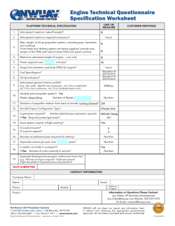


© Copyright 2026