
Propeller Project Board USB (#32810)
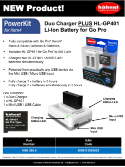
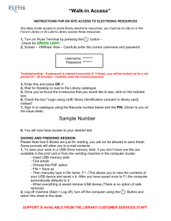
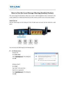
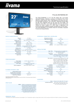
Web Site: www.parallax.com Forums: forums.parallax.com Sales: [email protected] Technical: [email protected] Office: (916) 624-8333 Fax: (916) 624-8003 Sales: (888) 512-1024 Tech Support: (888) 997-8267 Propeller Project Board USB (#32810) Parallax’s Propeller Project Board USB is a low cost solution for permanent projects using the multicore Propeller microcontroller. We have taken all the feedback and suggestions from our customers and designed this very DIY-friendly platform. The design offers more prototyping room and more features than its predecessor, the Propeller Proto Board USB (32812). In addition to prototyping with standard through-hole parts, you can take advantage of over 70 SMD pad options included on the board to save room and provide extra prototyping flexibility. If you have a project that needs a permanent platform, look no further, because the Propeller Project Board USB is your board! Features Propeller P8X32A-Q44 multicore microcontroller with access to all 32 I/O pins 64 KB EEPROM for program and data storage USB Powered (compatible with USB charging devices) Large prototyping area with 580 through-hole connections microSD card built-in mounting option (PN: 452-10015) SMD prototyping area o SO-64 connector (designed to be used with SO type SMD, 0603, 0805, 1206, SOT-223, CDFP’s and SSOP components) o 16 – SOT-23 connections (PN: 500-10016, 500-10011) VGA connector (Uses Parallax PN: 451-02061) All power, buttons and connectors at right angles for easy enclosure access QuickStart header, for QuickStart add-on boards Fixed 3.3 V, 1 A switching power regulator for better overall power consumption Removable 5 MHz crystal (add your own custom values) Power and over-voltage LED’s LDO Pad for your voltage regulation needs (REV B and later) Key Specifications Power Requirements: 5 VDC via USB, and/or 5–16 VDC via power connector pads o 3.3 VDC, 1 A switching regulator o VIN on board 16 V @ 3 A max Communication: USB for programming Operating temperature: -40 to +185 °F (-40 to +85 °C) Dimensions: 3.05 X 4 in (7.75 X 10.2 cm) Copyright © Parallax Inc. Propeller Project Board USB (#32810) v3.0 12/15/2014 Page 1 of 12 Propeller Project Board USB Features TOP (3) Removable 5 MHz Crystal (2) Propeller P8X32A µCU (1) Power LED (17) Reset Button (5) Switching Regulator 5–16 VDC in, 3.3 VDC @ 1 A out (6) microSD Pin Access (4) 64 KB EEPROM (10) Power Input - VIN 5–16 VDC, 3 A (14) VIN header, 3-pin (data, power, ground) (15) 64-pin SMT Pads & Pin Access (19) 40-pin QuickStart Header Socket Copyright © Parallax Inc. (9) VIN Over Voltage LED (7) VGA Pad & Pin Access (16) 3.3 VDC header, 3-pin (data, power, ground) (18) Propeller I/O Pin Access (all 32) (8) USB Port, VCP & 5 V Input (11) SOT-23 connections (13) Open Thru-hole Prototyping Area (12) 8-pin Bridge (top) and Ground Access (bottom) Propeller Project Board USB (#32810) v3.0 12/15/2014 Page 2 of 12 BOTTOM (20) LDO Voltage Regulator Pads (11) SOT-23 SMD Pads (6) microSD Card Holder Pad & Pin Access (15) 64-pin SMT Pads & Pin Access (1) Power LED This LED is always on when VIN has 4 VDC or more connected to it. It will not harm any circuitry if you decide to de-solder and remove this LED from the board. (2) Propeller P8X32A Microcontroller The Propeller P8X32A multicore microcontroller is designed for high-speed embedded processing while maintaining low power, low current consumption and a small physical footprint. More details and specifics about this chip can be found at www.parallax.com. (3) 5 MHz Crystal The 5 MHz crystal is removable. It can be replaced with a crystal of a different value, such as a 6.25 MHz crystal (Parallax #251-06250) for faster clocking speeds to the Propeller chip. Please refer to the Propeller Manual for proper specification on crystals. (4) 64 KB EEPROM The 64 KB EEPROM provides program and data storage for the Propeller microcontroller. It is accessible through Propeller I/O pins P28 and P29 Copyright © Parallax Inc. Propeller Project Board USB (#32810) v3.0 12/15/2014 Page 3 of 12 (5) Switching Regulator The switching regulator circuit provides 3.3 VDC to the board for the onboard Propeller chip and any other 3.3 V devices. Able to supply up to 1 A, it is highly efficient and useful for low-heat, low-energy projects. (6) microSD Card Holder Pad & Pin Access Pads for adding a microSD card holder (Parallax #452-10017) are included on bottom of the board. All the supporting circuitry needed to use a microSD card is already in place. DAT1, DAT0, CLK, CMD, CS/DAT3, DAT2 lines are brought to labeled thru-holes on the edge of the prototyping area. REV A NOTE: Use Parallax part number #452-10015 for the card holder. (7) VGA Pad and Pin Access Pads and thru-holes are provided support an optional slim-fit VGA connector, compatible with Parallax #451-02061. NOTE: REV A & B: Boards may have significant clock jitter when generating video with a high pixel rate due to high resolution and/or fast refresh rate. This may cause monitors to lose synch. Boards Rev C and later not affected; for more information see section (19) 40-pin QuickStart Header Socket, page 9. Once the VGA connector is in place, you will have access to vertical and horizontal synchronization, as well as red, green and blue. The only thing you need to do is connect the I/O pins you’re going to use. The support circuitry is built into the board (see schematic for details). (8) USB Port This port provides a virtual serial comm port interface from your computer to the Propeller P8X32A microcontroller. When connected it also provides power to the board’s 3.3 V switching regulator, making it easy to connect and program without the need for an external power source. The USB connection can supply no more than 500 mA, so if your if your project circuits connected to the 3.3 V rail require additional current, you will need to utilize the external power input. Power received through the USB port does not reach the VIN rail. To power circuits from the VIN rail, you must have an external power source connected. Protection is in place to make it safe to use USB power and the external power input at the same time. (Note: This board is compatible with USB chargers.) The board uses an FTDI chip to create the VCP interface. FTDI drivers are needed on your computer for your computer to recognize the connection. For the latest VCP drivers, visit FTDI’s website (www.ftdichip.com). Copyright © Parallax Inc. Propeller Project Board USB (#32810) v3.0 12/15/2014 Page 4 of 12 (9) Over Voltage LED This LED is in place as a small safety device, only turning on when VIN exceeds the rated voltage requirements. (10) Power Input — VIN The external power input connector was designed to provide many options for power supply connectivity: • Direct wire: 1/8” holes allow for wire gauges up to 12 AWG. • Alligator clips: the pads were made extra wide and long • Screw-down terminal: compatible with PN: 452-00012 is a good option that will fit. • Barrel jack: 2.1 mm center–positive connector, such as Parallax #452-00007. To supply power to the VIN header, you must apply 5–16 VDC to the external power input connector. The board can receive up to 500 mA for the 3.3 V rail via USB, but if your project requires additional current, external power input will be required. It is safe to apply power through the external power input while the board is connected to USB. Note: Remove the ground-disconnect pin from the #452-00007 barrel connector as shown below before soldering it to the board. (11) SOT-23 Connections and SMD Pads There are 16 SOT-23 pads included on the bottom of the board along the edge of the prototyping area. These are designed to make it easy to add transistors to your project. The three thru-holes that make up a single SOT-23 pad are labeled on the silkscreen on the top of the board, and numbered on both sides of the board. The image below gives an example of common placement for SOT-23 components. This view is from the bottom of the board, where there are solder pads around the thru-holes. Copyright © Parallax Inc. Propeller Project Board USB (#32810) v3.0 12/15/2014 Page 5 of 12 (12) 8-pin Bridge and Ground Access The 8-pin Bridge is a handy little area commonly used to connect an onboard regulator for convenient sharing of regulated power. For convince there is a LDO pad on the back of the board, that ties the LDO output pin to this bridge. It can also be used for pin sharing on any desired device without needing to create bridges. Just under the 8-Pin Bridge, there are 10 thru-holes connecting to ground. They are tied together to provide a convenient common ground connection for devices in the prototyping area. REV C NOTE: The pins labeled GND in the 9-pin bank are connected to each other, but not to the ground plane. Connect one pin in this bank to a pin in either of the GND pin banks across the bottom of the board. REV A NOTE: 6-pin Bridge on REV A boards have no connection to LDO Regulator pads. There are 12 ground thru-holes under the 6-pin Bridge. Copyright © Parallax Inc. Propeller Project Board USB (#32810) v3.0 12/15/2014 Page 6 of 12 (13) Open Thru-hole Prototyping Area The Propeller Project Board USB gives as much room as it can for adding your own components, ~5.78 square inches of thru-hole prototyping area with 0.1” spacing. The central portion of the prototyping area contains 13 x 29 grid of open, unlabeled thru-holes that are not connected to any components or optional-use solder pads on the board. This area has no ground plane or traces running through it. Drilling or cutting through this area will not affect the functionality of on-board circuitry. The two rows of thru-hole connections below the main prototyping area, labeled and numbered for optional use with SOT-23 parts, are also without a ground plane or traces. (14) VIN Header This header provides you with a VIN power rail. The board can handle up to 3 A at this header. This rail is powered from the external power input only. When the board is powered only through the USB port, this rail does not receive any power. It was designed to also utilize 3-pin servo connectors. (15) 64-pin SMT Area Pads & Pin Access These pads are for general surface mount use. They are long, thin pads with custom 0.65 mm spacing are designed to take a wide variety of SMT devices. Each pad has a connection to a thru-hole in the last two rows of the prototyping area for easy access to a mounted SMT device. A duplicate pad with the same connections is provided on the bottom of the board. Copyright © Parallax Inc. Propeller Project Board USB (#32810) v3.0 12/15/2014 Page 7 of 12 0.65 mm 0.37 mm 8.7 mm 2.2 mm Compatible device packages include, but not limited to SO type, 0603, 0805, SOT-223, CDFP and SSOP components. Below are just a few examples of how the Propeller Project Board’s SMD pads that can be used in your projects. Figure 1) Starting from left to right, a surface mount tantalum capacitor in a 1206 package; spans across the open area and connects to 4 pins total (two on each side). This is a shared pin connection since the pads on the part are larger than the pads on the board. The next part is an LED that has a unique package with leads that aren’t straight across; these types still work well with the SMD pads on the board. Next an EEPROM with an 8 pin TSSOP package, these parts align pin for pin. Next to that is a 3V regulator in a SOT-23-5 package, this part will still work well, the center pin is the only one that will share two pads on the board. The last part is large MOSFET as a TO-252-3 D-PAK; in this package a lot more board pins are used but, it’s still a usable setup. FIGURE (1) Figure 2) Starting from left to right, a surface mount Buck Regulator IC in a 8-SOIC package, fits well skipping over pins on the board. The next part is a Schottky diode in a SOD-123 package. This part spans the open area and fits well on the boards SMD pins. The last part is a FTDI FT232RL IC in a 28-SSOP package. It matches up to each pad, pin for pin. FIGURE (2) Copyright © Parallax Inc. Propeller Project Board USB (#32810) v3.0 12/15/2014 Page 8 of 12 (16) 3.3 VDC header This header provides regulated 3.3 VDC from the switching regulator. Pull up to 500 mA from this header when using USB power, or up to 1 A when using the external power input. It is designed to utilize 3-pin servo connectors (data, power, ground). (17) Reset Button This button resets the Propeller microcontroller. It is set up at a right angle for easy access when the board is mounted in an enclosure. (18) Propeller I/O Pin Access These thru-hole connections give you access to all 32 of the Propeller P8X32A’s I/O pins. See the Propeller Manual or datasheet for I/O pin details. (19) 40-pin QuickStart Header Socket This header utilizes the add-on boards that are compatible with the Propeller P8X32A QuickStart (#40000) For a list of boards that use this header please visit the QuickStart product page; browse to www.parallax.com and search “40000”. This socket can also be used for power and Propeller I/O pin access with or without male or female header for convenient connectivity. REV C NOTE: Access to XIN on the QuickStart Header was removed for Boards Rev C and later, to prevent VGA output problems; see (7) VGA Pad and Pin Access, page 4. Copyright © Parallax Inc. Propeller Project Board USB (#32810) v3.0 12/15/2014 Page 9 of 12 (20) LDO Voltage Regulator Pads These pads are in place for convenient connectivity to an LDO of your choice. The standard input pin is already wired to the positive side of VIN and the standard output pin is connected to the 8-pin bridge that runs alongside the board. Also, the standard grounds are already grounded. See the schematic below for reference on how the pads are wired. REV A NOTE: This feature is not included on REV A Boards. 8 PIN Bridge P9 P10 P164 P165 P166 P167 LDO PAD (TO-263) P168 P169 OUTPUT GROUND INPUT 3 2 VIN 1 GND Copyright © Parallax Inc. Propeller Project Board USB (#32810) v3.0 12/15/2014 Page 10 of 12 Pin Definitions & Assignments PIN P0-P27 P28-P29 SCL & SDA P30 & RX P31 & TX Definition/Assignment General-purpose I/O available on the QuickStart Header and alongside the board P28 = I²C Clock, P29 = I²C Data Connects to 64 KB EEPROM for non-volatile program and data storage RX serial communication to USB TX serial communication to USB D2 microSD DAT2, Data line bit 2, I/O type D3 microSD SD CD/DAT3, Card Detect/Data line bit 3, I/O type CD microSD SD CMD, Command/Response, Push pull type CK microSD SD CLK, Clock, Input type D0 microSD SD DAT0, Data line bit 0, I/O type D1 microSD SD DAT1, Data line bit 1, I/O type V VGA Vertical Sync H VGA Horizontal Sync The VGA RGB pins have sets of two resistors that form 0.7 volt, 75 Ω 2-bit DACs that are used to generate red, green and blue VGA Blue Video 510 Ω resistor B VGA Blue Video 240 Ω resistor with 130 Ω pull-down G R PWR_EN XI /RTS /CTS VGA Green Video 510 Ω resistor VGA Green Video 240 Ω resistor with 130 Ω pull-down VGA Red Video 510 Ω resistor VGA Red Video 240 Ω resistor with 130 Ω pull-down USB Power Enable pin, inverted. Pulled to USB 5V supply. Internally driven low after successful USB power negotiation. Propeller clock input. Do not load when not in use. Can drive the Propeller clock from an external signal, using the XINPUT directive. USB to serial converter Request To Send output, inverted. GND USB to serial converter Clear To Send input, inverted. Propeller reset pin, inverted. Pulled to VDD. Driven low on internal reset. Drive low to externally reset the Propeller. Ground VIN Voltage Input 5–16 VDC, 3 A RESn Copyright © Parallax Inc. Propeller Project Board USB (#32810) v3.0 12/15/2014 Page 11 of 12 4” (101.6mm) 3.7” (93.98mm) 0.125” (3.175mm) Dimensions 2.75” (69.85mm) 3.05” (77.473mm) Revision History Version 1.0: Original release. Version 2.0: Product has been updated to Rev B. Differences are noted in sections (6) microSD Card Holder Pad & Pin Access, page 4; (12) 8-pin Bridge and Ground Access, page 6; and (20) LDO Voltage Regulator Pads, page 10. Version 3.0: Adds Board Rev C support. Differences noted in sections (12) 8-pin Bridge and Ground Access, page 6; (7) VGA Pad and Pin Access, page 4; (19) 40-pin QuickStart Header Socket, page 9. Copyright © Parallax Inc. Propeller Project Board USB (#32810) v3.0 12/15/2014 Page 12 of 12


© Copyright 2026