
Programming for Computations - A Gentle Introduction to Numerical
Programming for Computations
- A Gentle Introduction to
Numerical MATLAB/Octave
Coding
Svein Linge1
Hans Petter Langtangen2
1
Telemark University College and Simula Research Laboratory
2
Simula Research Laboratory and University of Oslo
May 6, 2015
Preface
Computing, in the sense of doing mathematical calculations, is a skill
that mankind has developed over thousands of years. Programming,
on the other hand, is in its infancy, with a history that spans a few
decades only. Both topics are vastly comprehensive and usually taught
as separate subjects in educational institutions around the world. This
book is about the combination of the two, because computing today
becomes so much more powerful when combined with programming.
Most universities and colleges, however, require students to specialize in
computer science if they want to learn the craft of programming, since
other student programs usually do not offer programming to an extent
required for mastering this craft. Common arguments claim that it is
sufficient with a brief introduction, that there is not enough room for
learning programming in addition to all other must-have subjects, and
that there is so much software available that few really need to program
themselves. A consequence is that engineering students often graduate
with shallow knowledge about programming, unless they happened to
choose the computer science direction.
Is that an unfortunate situation? Yes! There is no doubt that practicing
engineers and scientists need to know their pen and paper mathematics.
They also must be able to run off-the-shelf software for important standard tasks, and will certainly do that a lot. Still, the benefits of solving
computing problems by programming are many:
1. Ready-made software is limited to handling certain standard problems.
What do you do when the problem on your desk is not covered by the
software you bought? Fortunately, a lot of modern software systems
are extensible via programming. In fact, many systems demand parts
of the problem specification (e.g., material models) to be given in
computer code.
v
Preface
2. With programming skills, you may extend the flexibility of existing
software packages by combining them. For example, you may integrate
packages that do not speak to each other from the outset. This may
simplify the work flow and allow new problem settings to be attacked.
3. It is easy to use excellent ready-made software the wrong way. Insight
in programming and the mathematics behind is fundamental for
understanding complex software, avoiding pitfalls, and become a safe
user.
4. Bugs (errors in computer code) are present in most larger computer
programs (also in the ones from the shop!). What do you do when
your ready-made software gives unexpected results? Is it a bug, is it
wrong use, or is it the mathematically correct result? The one who can
program, can make tailored code for a simplified problem setting and
use that to verify the computations done with off-the-shelf software.
5. Lots of skilled people around the world solve computational problems
by writing their own code and offer their code for free on the Internet.
To take advantage of this truly great source of software, one must
normally be able to understand (and possibly modify) computer code
offered by others.
6. It is recognized world wide that students struggle with standard
engineering subjects (mathematics, physics, etc.). Too many of them
find the subjects difficult and boring. With programming, we can
execute the good old subjects in a brand new way! According to
the authors’ own experience, students find it much more motivating
and enlightening when programming is made an integrated part of
mathematics or physical science courses. In particular, the problem
being solved can be much more realistic than when the mathematics
is restricted to what you can do with pen and paper.
7. Finally, we launch our most important argument for learning computer
programming: the algorithmic thinking that comes with the process of
writing a program for a computational problem enforces a thorough
understanding of both problem and solution method. We can simply
quote the famous Norwegian computer scientist Kristen Nyggaard:
“Programming is understanding”.
In the authors’ experience, programming is an excellent pedagogical tool
for understanding mathematics: “You think you know when you can
learn, are more sure when you can write, even more when you can teach,
but certain when you can program” (Alan Perlis, computer scientist,
1922-1990). Consider, for example, integration. A numerical method for
integration has a much stronger focus on what the integral actually is and
means (it is simply a sum!) compared to analytical methods, where much
time and effort must be devoted to integration by parts, integration by
substitution, etc. Moreover, when programming the numerical integration
formula, it becomes evident that it works for “all” mathematical functions
Preface
vii
and that the implementation should be in terms of a general function
applicable to “all” integrals. In this way, students learn to recognize a
special problem as belonging to a class of problems (e.g., integration,
differential equations, root finding), for which we have general numerical
methods implemented in widely applicable software. When they write
this software, as we do in this book, they learn how to generalize and
increase the abstraction level of the mathematical problem. When they
use this software, they learn how a special case should be attacked by
general methods and software for the class of problems that comprises
the special case at hand. This is the power of mathematics in a nutshell,
and it is paramount that students understand this way of thinking.
This book was written for students, teachers, engineers and scientists
that know nothing about programming and numerical methods from
before, but who seek a minimum of the fundamental skills required to get
started with programming as a tool for solving scientific and engineering
problems. Some knowledge of one- and multi-variable calculus is assumed.
The basic programming concepts are presented in only 50 pages (Chapters
1 and 2), before practical applications of these concepts are demonstrated
in important mathematical subjects addressed in the remaining parts of
the book (Chapters 3-6). The reader will realize that the modest content
of the first 50 pages can in fact bring you quite far in powerful problem
solving!
Learning the very basics of programming should not take long, but as
with any other craft, mastering the skill requires continued and extensive
practice. Some beginning practice is gained through Chapters 3-6, but
this is only a start. Students should continue to practice programming
in subsequent courses, while those who exercise self-study, should keep
up the learning process through continued application of the craft. The
book is a good starting point when teaching computer programming
as an integrated part of standard university courses in mathematics ad
physical sciences. In our experience, such an integration is doable and
very rewarding.
An overall goal with this book is to motivate computer programming
as a very powerful tool for doing mathematics. All examples are related
to mathematics and its use in engineering and science. However, to
solve mathematical problems through computer programming, we need
numerical methods. Explaining basic numerical methods is therefore an
integral part of the book. Our choice of topics is governed by what is
most needed in science and engineering, as well as in the teaching of
applied physical science courses. Mathematical models are then central,
with differential equations constituting the most frequent type of models.
Consequently, the numerical focus in this book is on ordinary and partial
differential equations. As a soft pedagogical starter for the programming
of mathematics, we have chosen the topic of numerical integration. There
is also a chapter on root finding, which is important for the numerical
Preface
solving of several kinds of ODEs and PDEs. We remark that the book is
deliberately brief on numerical methods, since our focus is on the basic
ideas and understanding of numerical approximations, before going into
all details about how the methods are turned into working programs.
We have chosen to use the programming language Matlab, because this
language gives very compact and readable code that closely resembles
the mathematical recipe for solving the problem at hand. Matlab also
has a gentle learning curve. There is a Python companion of this book if
that language is preferred. We use the expression Matlab throughout the
book to mean the commercial MATLAB (R) software [3] or the open
source alternative Octave [1]. Comparing the two versions of the book
provides an excellent example on how similar these languages are. Other
computer languages, like Fortran, C, and C++, have a strong position in
science and engineering, but during the last two decades, there has been
a significant shift in popularity from these compiled languages to more
high-level and easier-to-read languages like Matlab, Python, R, Maple,
Mathematica, and IDL, for instance. This latter class of languages is
computationally less efficient, but superior with respect to overall human
problem solving efficiency. This book emphasizes how to think like a
programmer, rather than focusing on technical language details. Thus,
the book should put the reader in a good position for learning other
programming languages later, including the classic ones: Fortran, C, and
C++.
There are numerous texts on computer programming and numerical
methods, so how does the present one differ from the existing literature?
Compared to books on numerical methods, our book has a much stronger
emphasis on the craft of programming and on verification. We want
to teach students a thorough understanding of how one thinks about
programming as a problem solving method and how one can be sure that
programs are correct (well, you can never be, but we show how you can
provide evidence for correctness).
Even though there are lots of books on numerical methods where
most algorithms have a corresponding computer implementation, it is
assumed that the reader “can program” beforehand. The present book
teaches the craft of programming along with the numerical methods.
Furthermore, we have so far not found any other numerical methods book
that has a strong emphasis on verifying implementations. In this book,
unit testing and corresponding test functions are introduced early on. We
also put much emphasis on coding algorithms as functions, as opposed
to “flat programs”, which often dominates in the literature and among
practitioners. Functions are reusable because they utilize the general
formulation of a mathematical algorithm such that it becomes applicable
to a large class of problems.
There are also numerous books on computer programming, but few
that aim to teach programming in the context of numerical methods.
Preface
ix
Those that do, have a primary focus on teaching the programming
language. For example, one of the authors has a book on Python programming of numerical methods and their applications (A Primer on
Scientific Programming with Python, Springer, 4th edition, 2014 [2]),
but that book is a very comprehensive introduction to Python as a
language and the thinking about programming as a computer scientist.
Sometimes one needs a course and a text that do not go so deep into the
language-specific details, but instead targets the shortest path to reliable
mathematical problem solving through programming. Consequently, a
lot of topics, object-oriented programming being one, are therefore left
out of the present book, because we did not feel a strong need for it in
the mathematical problem solving process.
Whenever the need for programming arises in science and engineering
courses, this book may your option, either for self-study or for use in
organized teaching. The thinking, habits, and practice covered in a couple
of hundred pages will put readers in a firm position for utilizing and
understanding the power of computers to solve problems in science and
engineering.
Acknowledgement to Edirisinghe V.P.J. Manjula for his careful reading
of the manuscript and for his constructive suggestions for improvement.
Contents
1
2
The first few steps . . . . . . . . . . . . . . . . . . . . . . . . . . . . . . . . . .
1.1 What is a program? And what is programming? . . . . . . .
1.2 A Matlab program with variables . . . . . . . . . . . . . . . . . . . .
1.2.1 The program . . . . . . . . . . . . . . . . . . . . . . . . . . . . . . . .
1.2.2 Dissection of the program . . . . . . . . . . . . . . . . . . . . .
1.2.3 Why not just use a pocket calculator? . . . . . . . . . .
1.2.4 The importance of using a text editor to write
programs . . . . . . . . . . . . . . . . . . . . . . . . . . . . . . . . . . .
1.2.5 Write and run your first program . . . . . . . . . . . . . .
1.3 A Matlab program with a library function . . . . . . . . . . . .
1.4 A Matlab program with vectorization and plotting . . . . .
1.5 More basic concepts . . . . . . . . . . . . . . . . . . . . . . . . . . . . . . .
1.5.1 Using Matlab interactively . . . . . . . . . . . . . . . . . . . .
1.5.2 Arithmetics, parentheses and round-off errors . . . .
1.5.3 Variables . . . . . . . . . . . . . . . . . . . . . . . . . . . . . . . . . . .
1.5.4 Formatting text and numbers . . . . . . . . . . . . . . . . .
1.5.5 Arrays . . . . . . . . . . . . . . . . . . . . . . . . . . . . . . . . . . . . .
1.5.6 Plotting . . . . . . . . . . . . . . . . . . . . . . . . . . . . . . . . . . . .
1.5.7 Error messages and warnings . . . . . . . . . . . . . . . . . .
1.5.8 Input data . . . . . . . . . . . . . . . . . . . . . . . . . . . . . . . . . .
1.5.9 Symbolic computations . . . . . . . . . . . . . . . . . . . . . . .
1.5.10 Concluding remarks . . . . . . . . . . . . . . . . . . . . . . . . . .
1.6 Exercises . . . . . . . . . . . . . . . . . . . . . . . . . . . . . . . . . . . . . . . . .
1
1
4
4
4
6
6
7
8
9
11
11
12
13
14
15
17
19
21
21
23
24
Basic constructions . . . . . . . . . . . . . . . . . . . . . . . . . . . . . . . . . .
2.1 If tests, colon and indentation . . . . . . . . . . . . . . . . . . . . . . .
2.2 Functions . . . . . . . . . . . . . . . . . . . . . . . . . . . . . . . . . . . . . . . .
2.3 For loops . . . . . . . . . . . . . . . . . . . . . . . . . . . . . . . . . . . . . . . . .
2.4 While loops . . . . . . . . . . . . . . . . . . . . . . . . . . . . . . . . . . . . . .
29
29
31
36
39
xi
Contents
3
4
2.5 Reading from and writing to files . . . . . . . . . . . . . . . . . . . .
2.6 Exercises . . . . . . . . . . . . . . . . . . . . . . . . . . . . . . . . . . . . . . . . .
40
42
Computing integrals . . . . . . . . . . . . . . . . . . . . . . . . . . . . . . . .
3.1 Basic ideas of numerical integration . . . . . . . . . . . . . . . . . .
3.2 The composite trapezoidal rule . . . . . . . . . . . . . . . . . . . . . .
3.2.1 The general formula . . . . . . . . . . . . . . . . . . . . . . . . . .
3.2.2 Implementation . . . . . . . . . . . . . . . . . . . . . . . . . . . . .
3.2.3 Alternative flat special-purpose implementation . .
3.3 The composite midpoint method . . . . . . . . . . . . . . . . . . . .
3.3.1 The general formula . . . . . . . . . . . . . . . . . . . . . . . . . .
3.3.2 Implementation . . . . . . . . . . . . . . . . . . . . . . . . . . . . .
3.3.3 Comparing the trapezoidal and the midpoint
methods . . . . . . . . . . . . . . . . . . . . . . . . . . . . . . . . . . . .
3.4 Testing . . . . . . . . . . . . . . . . . . . . . . . . . . . . . . . . . . . . . . . . . .
3.4.1 Problems with brief testing procedures . . . . . . . . .
3.4.2 Test procedures . . . . . . . . . . . . . . . . . . . . . . . . . . . . .
3.4.3 Constructing unit tests and writing test functions
3.5 Vectorization . . . . . . . . . . . . . . . . . . . . . . . . . . . . . . . . . . . . .
3.6 Measuring computational speed . . . . . . . . . . . . . . . . . . . . .
3.7 Double and triple integrals . . . . . . . . . . . . . . . . . . . . . . . . .
3.7.1 The midpoint rule for a double integral . . . . . . . . .
3.7.2 The midpoint rule for a triple integral . . . . . . . . . .
3.7.3 Monte Carlo integration for complex-shaped
domains . . . . . . . . . . . . . . . . . . . . . . . . . . . . . . . . . . . .
3.8 Exercises . . . . . . . . . . . . . . . . . . . . . . . . . . . . . . . . . . . . . . . . .
53
54
55
57
58
60
62
63
64
Solving ordinary differential equations . . . . . . . . . . . . . . .
4.1 Population growth . . . . . . . . . . . . . . . . . . . . . . . . . . . . . . . . .
4.1.1 Derivation of the model . . . . . . . . . . . . . . . . . . . . . .
4.1.2 Numerical solution . . . . . . . . . . . . . . . . . . . . . . . . . . .
4.1.3 Programming the Forward Euler scheme; the
special case . . . . . . . . . . . . . . . . . . . . . . . . . . . . . . . . .
4.1.4 Understanding the Forward Euler method . . . . . . .
4.1.5 Programming the Forward Euler scheme; the
general case . . . . . . . . . . . . . . . . . . . . . . . . . . . . . . . . .
4.1.6 Making the population growth model more realistic
4.1.7 Verification: exact linear solution of the discrete
equations . . . . . . . . . . . . . . . . . . . . . . . . . . . . . . . . . . .
4.2 Spreading of diseases . . . . . . . . . . . . . . . . . . . . . . . . . . . . . .
4.2.1 Spreading of a flu . . . . . . . . . . . . . . . . . . . . . . . . . . . .
4.2.2 A Forward Euler method for the differential
equation system . . . . . . . . . . . . . . . . . . . . . . . . . . . . .
4.2.3 Programming the numerical method; the special
case . . . . . . . . . . . . . . . . . . . . . . . . . . . . . . . . . . . . . . . .
89
90
91
93
64
65
65
66
68
71
72
73
73
76
78
82
96
98
99
101
104
105
105
108
109
Contents
xiii
4.2.4 Outbreak or not . . . . . . . . . . . . . . . . . . . . . . . . . . . . .
4.2.5 Abstract problem and notation . . . . . . . . . . . . . . . .
4.2.6 Programming the numerical method; the general
case . . . . . . . . . . . . . . . . . . . . . . . . . . . . . . . . . . . . . . . .
4.2.7 Time-restricted immunity . . . . . . . . . . . . . . . . . . . . .
4.2.8 Incorporating vaccination . . . . . . . . . . . . . . . . . . . . .
4.2.9 Discontinuous coefficients: a vaccination campaign
4.3 Oscillating one-dimensional systems . . . . . . . . . . . . . . . . . .
4.3.1 Derivation of a simple model . . . . . . . . . . . . . . . . . .
4.3.2 Numerical solution . . . . . . . . . . . . . . . . . . . . . . . . . . .
4.3.3 Programming the numerical method; the special
case . . . . . . . . . . . . . . . . . . . . . . . . . . . . . . . . . . . . . . . .
4.3.4 A magic fix of the numerical method . . . . . . . . . . .
4.3.5 The 2nd-order Runge-Kutta method (or Heun’s
method) . . . . . . . . . . . . . . . . . . . . . . . . . . . . . . . . . . . .
4.3.6 Odespy: software for solving ODEs . . . . . . . . . . . . .
4.3.7 The 4th-order Runge-Kutta method . . . . . . . . . . . .
4.3.8 More effects: damping, nonlinearity, and external
forces . . . . . . . . . . . . . . . . . . . . . . . . . . . . . . . . . . . . . .
4.3.9 Illustration of linear damping . . . . . . . . . . . . . . . . . .
4.3.10 Illustration of linear damping with sinusoidal
excitation . . . . . . . . . . . . . . . . . . . . . . . . . . . . . . . . . . .
4.3.11 Spring-mass system with sliding friction . . . . . . . .
4.3.12 A finite difference method; undamped, linear case
4.3.13 A finite difference method; linear damping . . . . . .
4.4 Exercises . . . . . . . . . . . . . . . . . . . . . . . . . . . . . . . . . . . . . . . . .
5
6
110
112
112
114
116
117
119
120
121
122
123
126
128
134
136
139
142
143
145
147
149
Solving partial differential equations . . . . . . . . . . . . . . . . .
5.1 Finite difference methods . . . . . . . . . . . . . . . . . . . . . . . . . . .
5.1.1 Reduction of a PDE to a system of ODEs . . . . . . .
5.1.2 Construction of a test problem with known
discrete solution . . . . . . . . . . . . . . . . . . . . . . . . . . . . .
5.1.3 Implementation: Forward Euler method . . . . . . . . .
5.1.4 Application: heat conduction in a rod . . . . . . . . . .
5.1.5 Vectorization . . . . . . . . . . . . . . . . . . . . . . . . . . . . . . . .
5.1.6 Using Odespy to solve the system of ODEs . . . . . .
5.1.7 Implicit methods . . . . . . . . . . . . . . . . . . . . . . . . . . . .
5.2 Exercises . . . . . . . . . . . . . . . . . . . . . . . . . . . . . . . . . . . . . . . . .
159
162
162
165
165
167
171
172
173
176
Solving nonlinear algebraic equations . . . . . . . . . . . . . . . .
6.1 Brute force methods . . . . . . . . . . . . . . . . . . . . . . . . . . . . . . .
6.1.1 Brute force root finding . . . . . . . . . . . . . . . . . . . . . . .
6.1.2 Brute force optimization . . . . . . . . . . . . . . . . . . . . . .
6.1.3 Model problem for algebraic equations . . . . . . . . . .
6.2 Newton’s method . . . . . . . . . . . . . . . . . . . . . . . . . . . . . . . . .
183
184
185
187
188
189
Contents
6.3
6.4
6.5
6.6
6.2.1 Deriving and implementing Newton’s method . . . .
6.2.2 Making a more efficient and robust implementation
The secant method . . . . . . . . . . . . . . . . . . . . . . . . . . . . . . . .
The bisection method . . . . . . . . . . . . . . . . . . . . . . . . . . . . . .
Rate of convergence . . . . . . . . . . . . . . . . . . . . . . . . . . . . . . .
Exercises . . . . . . . . . . . . . . . . . . . . . . . . . . . . . . . . . . . . . . . . .
189
192
195
197
199
201
References . . . . . . . . . . . . . . . . . . . . . . . . . . . . . . . . . . . . . . . . . . . . . .
205
Index . . . . . . . . . . . . . . . . . . . . . . . . . . . . . . . . . . . . . . . . . . . . . . . . . . .
207
List of Exercises
Exercise
Exercise
Exercise
Exercise
Exercise
Exercise
Exercise
Exercise
Exercise
Exercise
Exercise
Exercise
Exercise
Exercise
Exercise
Exercise
Exercise
Exercise
Exercise
Exercise
Exercise
Exercise
Exercise
Exercise
Exercise
Exercise
Exercise
Exercise
Exercise
Exercise
1.1: Error messages . . . . . . . . . . . . . . . . . . . . . . . . . . . . . . . .
1.2: Volume of a cube . . . . . . . . . . . . . . . . . . . . . . . . . . . . . .
1.3: Area and circumference of a circle . . . . . . . . . . . . . . .
1.4: Volumes of three cubes . . . . . . . . . . . . . . . . . . . . . . . . .
1.5: Average of integers . . . . . . . . . . . . . . . . . . . . . . . . . . . . .
1.6: Interactive computing of volume and area . . . . . . . . .
1.7: Update variable at command prompt . . . . . . . . . . . . .
1.8: Formatted print to screen . . . . . . . . . . . . . . . . . . . . . . .
1.9: Matlab documentation and random numbers . . . . . .
2.1: Introducing errors . . . . . . . . . . . . . . . . . . . . . . . . . . . . .
2.2: Compare integers a and b . . . . . . . . . . . . . . . . . . . . . . .
2.3: Functions for circumference and area of a circle . . . .
2.4: Function for area of a rectangle . . . . . . . . . . . . . . . . . .
2.5: Area of a polygon . . . . . . . . . . . . . . . . . . . . . . . . . . . . .
2.6: Average of integers . . . . . . . . . . . . . . . . . . . . . . . . . . . . .
2.7: While loop with errors . . . . . . . . . . . . . . . . . . . . . . . . .
2.8: Area of rectangle versus circle . . . . . . . . . . . . . . . . . . .
2.9: Find crossing points of two graphs . . . . . . . . . . . . . . .
2.10: Sort array with numbers . . . . . . . . . . . . . . . . . . . . . . .
2.11: Compute π . . . . . . . . . . . . . . . . . . . . . . . . . . . . . . . . . .
2.12: Compute combinations of sets . . . . . . . . . . . . . . . . . .
2.13: Frequency of random numbers . . . . . . . . . . . . . . . . . .
2.14: Game 21 . . . . . . . . . . . . . . . . . . . . . . . . . . . . . . . . . . . .
2.15: Linear interpolation . . . . . . . . . . . . . . . . . . . . . . . . . . .
2.16: Test straight line requirement . . . . . . . . . . . . . . . . . .
2.17: Fit straight line to data . . . . . . . . . . . . . . . . . . . . . . .
2.18: Fit sines to straight line . . . . . . . . . . . . . . . . . . . . . . .
2.19: Count occurrences of a string in a string . . . . . . . . .
3.1: Hand calculations for the trapezoidal method . . . . . .
3.2: Hand calculations for the midpoint method . . . . . . .
24
25
25
25
26
26
26
26
27
42
42
43
43
43
44
44
44
45
45
45
46
46
47
47
48
48
49
50
82
83
xv
List of Exercises
Exercise 3.3: Compute a simple integral . . . . . . . . . . . . . . . . . . . . . .
Exercise 3.4: Hand-calculations with sine integrals . . . . . . . . . . . . .
Exercise 3.5: Make test functions for the midpoint method . . . . . .
Exercise 3.6: Explore round-off errors Rwith large numbers . . . . . . .
√
Exercise 3.7: Write test functions for 04 xdx . . . . . . . . . . . . . . . . .
Exercise 3.8: Rectangle methods . . . . . . . . . . . . . . . . . . . . . . . . . . . .
Exercise 3.9: Adaptive integration . . . . . . . . . . . . . . . . . . . . . . . . . . .
Exercise 3.10: Integrating x raised to x . . . . . . . . . . . . . . . . . . . . . . .
Exercise 3.11: Revisit fit of sines to a function . . . . . . . . . . . . . . . . .
Exercise 3.12: Derive the trapezoidal rule for a double integral . .
Exercise 3.13: Compute the area of a triangle by Monte Carlo
integration . . . . . . . . . . . . . . . . . . . . . . . . . . . . . . . . . .
Exercise 4.1: Geometric construction of the Forward Euler method
Exercise 4.2: Make test functions for the Forward Euler method .
Exercise 4.3: Implement and evaluate Heun’s method . . . . . . . . . .
Exercise 4.4: Find an appropriate time step; logistic model . . . . . .
Exercise 4.5: Find an appropriate time step; SIR model . . . . . . . .
Exercise 4.6: Model an adaptive vaccination campaign . . . . . . . . .
Exercise 4.7: Make a SIRV model with time-limited effect of
vaccination . . . . . . . . . . . . . . . . . . . . . . . . . . . . . . . . . .
Exercise 4.8: Refactor a flat program . . . . . . . . . . . . . . . . . . . . . . . . .
Exercise 4.9: Simulate oscillations by a general ODE solver . . . . .
Exercise 4.10: Compute the energy in oscillations . . . . . . . . . . . . . .
Exercise 4.11: Use a Backward Euler scheme for population growth
Exercise 4.12: Use a Crank-Nicolson scheme for population growth
Exercise 4.13: Understand finite differences via Taylor series . . . .
Exercise 4.14: Use a Backward Euler scheme for oscillations . . . . .
Exercise 4.15: Use Heun’s method for the SIR model . . . . . . . . . . .
Exercise 4.16: Use Odespy to solve a simple ODE . . . . . . . . . . . . . .
Exercise 4.17: Set up a Backward Euler scheme for oscillations . .
Exercise 4.18: Set up a Forward Euler scheme for nonlinear and
damped oscillations . . . . . . . . . . . . . . . . . . . . . . . . . . .
Exercise 4.19: Discretize an initial condition . . . . . . . . . . . . . . . . . .
Exercise 5.1: Simulate a diffusion equation by hand . . . . . . . . . . . .
Exercise 5.2: Compute the temperature variations in the ground .
Exercise 5.3: Compare implicit methods . . . . . . . . . . . . . . . . . . . . . .
Exercise 5.4: Explore adaptive and implicit methods . . . . . . . . . . .
Exercise 5.5: Investigate the θ rule . . . . . . . . . . . . . . . . . . . . . . . . . . .
Exercise 5.6: Compute the diffusion of a Gaussian peak . . . . . . . .
Exercise 5.7: Vectorize a function for computing the area of a
polygon . . . . . . . . . . . . . . . . . . . . . . . . . . . . . . . . . . . . .
Exercise 5.8: Explore symmetry . . . . . . . . . . . . . . . . . . . . . . . . . . . . .
Exercise 5.9: Compute solutions as t → ∞ . . . . . . . . . . . . . . . . . . . .
Exercise 5.10: Solve a two-point boundary value problem . . . . . . .
Exercise 6.1: Understand why Newton’s method can fail . . . . . . . .
83
83
83
83
84
84
85
85
86
87
87
149
149
150
150
150
151
151
151
152
152
152
153
154
155
156
156
156
157
157
176
177
178
178
178
179
180
180
181
182
201
List of Exercises
xvii
Exercise 6.2: See if the secant method fails . . . . . . . . . . . . . . . . . . . .
Exercise 6.3: Understand how the bisection method cannot fail . .
Exercise 6.4: Combine the bisection method with Newton’s method
Exercise 6.5: Write a test function for Newton’s method . . . . . . . .
Exercise 6.6: Solve nonlinear equation for a vibrating beam . . . . .
201
202
202
202
203
The first few steps
1
1.1 What is a program? And what is programming?
Today, most people are experienced with computer programs, typically
programs such as Word, Excel, PowerPoint, Internet Explorer, and Photoshop. The interaction with such programs is usually quite simple and
intuitive: you click on buttons, pull down menus and select operations,
drag visual elements into locations, and so forth. The possible operations
you can do in these programs can be combined in seemingly an infinite
number of ways, only limited by your creativity and imagination.
Nevertheless, programs often make us frustrated when they cannot
do what we wish. One typical situation might be the following. Say you
have some measurements from a device, and the data are stored in a file
with a specific format. You may want to analyze these data in Excel and
make some graphics out of it. However, assume there is no menu in Excel
that allows you to import data in this specific format. Excel can work
with many different data formats, but not this one. You start searching
for alternatives to Excel that can do the same and read this type of data
1
2
1 The first few steps
files. Maybe you cannot find any ready-made program directly applicable.
You have reached the point where knowing how to write programs on
your own would be of great help to you! With some programming skills,
you may write your own little program which can translate one data
format to another. With that little piece of tailored code, your data may
be read and analyzed, perhaps in Excel, or perhaps by a new program
tailored to the computations that the measurement data demand.
The real power of computers can only be utilized if you can program
them. By programming you can get the computer to do (most often!)
exactly what you want. Programming consists of writing a set of instructions in a very specialized language that has adopted words and
expressions from English. Such languages are known as programming or
computer languages. The set of instructions is given to a program which
can translate the meaning of the instructions into real actions inside the
computer.
The purpose of this book is to teach you to write such instructions dedicated to solve mathematical and engineering problems by fundamental
numerical methods.
There are numerous computer languages for different purposes. Within
the engineering area, the most widely used computer languages are
Python, Matlab, Octave, Fortran, C, C++, and to some extent Maple,
and Mathematica. How you write the instructions (i.e. the syntax) differs
between the languages. Let us use an analogy.
Assume you are an international kind of person, having friends abroad
in England, Russia and China. They want to try your favorite cake.
What can you do? Well, you may write down the recipe in those three
languages and send them over. Now, if you have be able to think correctly
when writing down the recipe, and you have written the explanations
according to the rules in each language, each of your friends will produce
the same cake. Your recipe is the “computer program”, while English,
Russian and Chinese represent the “computer languages” with their own
rules of how to write things. The end product, though, is still the same
cake. Note that you may unintentionally introduce errors in your “recipe”.
Depending on the error, this may cause “baking execution” to stop, or
perhaps produce the wrong cake. In your computer program, the errors
you introduce are called bugs (yes, small insects! ...for historical reasons),
and the process of fixing them is called debugging. When you try to run
your program that contains errors, you usually get warnings or error
messages. However, the response you get depends on the error and the
programming language. You may even get no response, but simply the
wrong “cake”. Note that the rules of a programming language have to be
followed very strictly. This differs from languages like English etc., where
the meaning might be understood even if with spelling errors and “slang”
included.
1.1 What is a program? And what is programming?
This book comes in two versions, one that is based on Python, and
one based on Matlab. Both Python and Matlab represent excellent
programming environments for scientific and engineering tasks. The
version you are reading now, is the Matlab version.
Readers who want to expand their scientific programming skills beyond
the introductory level of the present exposition, are encouraged to study
A Primer on Scientific Programming with Python, 4th edition, by H.P.
Langtangen, and published by Springer in 2014. This comprehensive book
is as suitable for beginners as well as for professional programmers, and
teaches the art of programming through a huge collection of dedicated
examples. This book is considered the primary reference, and a natural
extension, of the programming matters in the present book.
For details on Matlab syntax and programming we refer the reader to
(ref.), whereas a to-the-point discussion (with programming examples)
of relevant programming languages like Python, Matlab, Fortran and C
may be found in Tveito et al.: Elements of Scientific Computing, Ch 6.,
Springer, 2010.
Many excellent books may be consulted for deeper insight into the
mathematical methods presented herein. We mention a few of those, e.g.,
Numerical Mathematics, 2nd ed, 2007, Springer Verlag, by Quarteroni et.
al, and Numerical Methods in Scientific Computing, Vol. 1 and 2, 2nd
edition, 2008, by Dahlquist and Björk, Springer. The book Numerical
Methods that work, 4th edition, 1990, by Acton F.S. is somewhat older,
but many important points therein are as relevant today. Some of the
exercises in the present book were motivated from discussions in these
books.
Let us now turn to an actual Matlab program and see what it looks
like.
Some computer science terms
Note that, quite often, the terms script and scripting are used as
synonyms for program and programming, respectively, especially
when using Matlab and a few lines of code can do much.
The inventor of the Perl programming language, Larry Wall, tried
to explain the difference between script and program in a humorous
way (from perl.com): Suppose you went back to Ada Lovelace and
asked her the difference between a script and a program. She’d
probably look at you funny, then say something like: Well, a script
is what you give the actors, but a program is what you give the
audience. That Ada was one sharp lady... Since her time, we seem
to have gotten a bit more confused about what we mean when we
say scripting. It confuses even me, and I’m supposed to be one of
the experts.
3
4
1 The first few steps
There are many other widely used computer science terms to
pick up. Writing a program (or script or code) is often expressed as
implementing the program. Executing a program means running the
program. An algorithm is a recipe for how to construct a program.
A bug is an error in a program, and the art of removing bugs is
called debugging.
1.2 A Matlab program with variables
Let us assume a ball that is thrown straight up. From Newton’s 2nd law,
and by assuming negligible air resistance, one can derive a mathematical
model that gives the vertical position y of the ball with time t. It reads
y = v0 t − 0.5gt2 ,
where v0 is the initial upwards velocity and g is the acceleration of gravity,
for which 9.81 ms−2 is a reasonable value (even if it depends on things
like location on the earth). With this formula at hand, and when v0 is
known, you may plug in a value for time and get out the corresponding
height.
1.2.1 The program
Let us next look at a Matlab program for this very simple mathematical
model. Assume the program is contained as text in a file named ball.m.
The text looks as follows (file ball.m):
% Program for computing the height of a ball in vertical motion
v0 = 5;
g = 9.81;
t = 0.6;
% Initial velocity
% Acceleration of gravity
% Time
y = v0*t - 0.5*g*t^2
% Vertical position
1.2.2 Dissection of the program
A computer program is plain text, as here in the file ball.m, which
contains instructions to the computer. Humans can read the code and
understand what the program is capable of doing, but the program itself
does not trigger any actions on a computer before a special program on
the computer reads the program text and translates this text into specific
1.2 A Matlab program with variables
5
actions. The particular text in ball.m must be read and understood by
Matlab.
Although Matlab is responsible for reading and understanding your
program, it is of fundamental importance that you fully understand the
program yourself. You have to know the implication of every instruction in
the program and be able to figure out the consequences of the instructions.
In other words, you must be able to play a computer. The reason for this
strong demand of knowledge is that you very often commit errors in the
program text, and to track down these errors, you have to simulate what
the computer does with the program. Next, we shall explain all the text
in ball.m in full detail.
Matlab will next start to read your file, line by line, from the top. The
first line it reads is
% Program for computing the height of a ball in vertical motion.
This line is what we call a comment. That is, the line is not meant for
Matlab to read and execute, but rather for a human that reads the code
and tries to understand what is going on. Therefore, one rule in Matlab
says that whenever Matlab encounters the sign % it takes the rest of the
line as a comment. Matlab then simply skips reading the rest of the line
and jumps to the next line. In the code, you see several such comments
and probably realize that they make it easier for you to understand
(or guess) what is meant with the code. In this simple cases, comments
are probably not much needed, but will soon be justified as the level of
complexity steps up.
The next line read by Matlab is
v0 = 5;
% Initial velocity
According to its rules, Matlab will now create a variable with the
name v0 and set (the value of) that variable equal to 5. We say that 5 is
assigned to v0. This means that whenever Matlab reads v0 hereafter, it
plugs in 5 instead of the name v0, since it knows that v0 has the value 5.
You may think of v0 as a variable v0 in mathematics. The next two lines
g = 9.81;
t = 0.6;
% Acceleration of gravity
% Time
are of the same kind, so having read them too, Matlab knows of three
variables (v0, g, t) and their values. These variables are then used by
Matlab when it reads the next line, the actual “formula”,
y = v0*t - 0.5*g*t^2
% Vertical position
Again, according to its rules, Matlab interprets * as multiplication, - as
minus and ^ as exponent (let us also add here that, not surprisingly,
+ and / would have been understood as addition and division, if such
6
1 The first few steps
signs had been present in the expression). Having read the line, Matlab
performs the mathematics on the right-hand side, and then assigns the
result (in this case the number 1.2342) to the variable y. Also, since the
final line has no semi-colon, Matlab understands that we also want the
result printed to screen. When ball.m is run, the number 1.2342 appears
on the screen.
Note that the "skipping" of semi-colon provides an easy way to print
things to screen in general. Simply writing, e.g., v0 in the program above,
i.e. without the semi-colon, will make the content of v0 be printed to
screen.
In the code above, you see several blank lines too. These are simply
skipped by Matlab and you may use as many as you want to make a
nice and readable layout of the code.
1.2.3 Why not just use a pocket calculator?
Certainly, finding the answer as done by the program above could easily
have been done with a pocket calculator. No objections to that and no
programming would have been needed. However, what if you would like
to have the position of the ball for every milli-second of the flight? All
that punching on the calculator would have taken you something like
four hours! If you know how to program, however, you could modify
the code above slightly, using a minute or two of writing, and easily
get all the positions computed in one go within a second. A much
stronger argument, however, is that mathematical models from real life
are often complicated and comprehensive. The pocket calculator cannot
cope with such problems, even not the programmable ones, because
their computational power and their programming tools are far too weak
compared to a real computer.
1.2.4 The importance of using a text editor to write
programs
When Matlab interprets some code in a file, it is concerned with every
character in the file, exactly as it was typed in. This makes it troublesome
to write the code into a file with word processors like, e.g., Microsoft
Word, since such a program will insert extra characters, invisible to us,
with information on how to format the text (e.g., the font size and type).
Such extra information is necessary for the text to be nicely formatted
for the human eye. Matlab will be much annoyed by the extra characters
in the file inserted by a word processor. Therefore, it is fundamental that
you write your program in a text editor where what you type on the
keyboard is exactly the characters that appear in the file and that Matlab
1.2 A Matlab program with variables
will later read. There are many text editors around. Some are standalone programs like Emacs, Vim, Gedit, Notepad++, and TextWrangler.
Many prefer to use the text editor that comes with the graphical Matlab
environment.
1.2.5 Write and run your first program
Reading only does not teach you computer programming: you have to
program yourself and practice heavily before you master mathematical
problem solving via programming. Therefore, it is crucial that you at
this stage write and run a Matlab program.
But first a warning: there are many things at that must play together
correctly for the above program to run correctly on your computer. There
might be problems with your Matlab installation, with your writing of
the program (it is very easy to introduce errors!), or with the location
of the file, just to mention some of the most common difficulties for
beginners. Fortunately, such problems are solvable, and if you do not
understand how to fix the problem, ask somebody. Typically, once you
are beyond these common start-up problems, you can move on to learn
programming and how programs can do a lot of otherwise complicated
mathematics for you.
The term Matlab refers to both the software package Matlab from
MathWorks Inc., and the programming language Matlab. Matlab programs can either be run in the commercial Matlab software package, or
they can be run in the free GNU Octave software, usually just called
Octave. We first describe how to operate the Matlab software and then
Octave.
The first step is to generate a directory in which you will place your
future Matlab code. Do this in a terminal window (Terminal on Mac,
Power Shell or Command Prompt on Windows, or (e.g.) gnome-terminal
on Linux). Write mkdir mycode to create a directory with name mycode.
Then move into that directory by writing cd mycode.
Write and run a program in Matlab. Start Matlab and try out the
following.
1. Write the Matlab program ball.m. Do this by choosing
File/New/Script from the menu in the Command window. In the
editor window that pops up, simply write the code lines there as they
were given above for ball.m. Now save this with the name "ball.m"
in the right directory, i.e. MyCode, via Save As from the File menu.
The program is now ready for use!
2. Run the program. Do this in the Command window by writing the
name of the program without the extension, i.e. write "ball", and press
enter. Matlab will now run the program.
7
8
1 The first few steps
Write a program in a text editor and run it in Octave. Octave users
must write the program in a plain text editor such as Gedit on Linux
computers; TextWrangler on Mac, or Notepad++ on Windows. Popular,
but more advanced text editors, primarily Emacs and Vim, are also
available for these platforms.
1. Write the Matlab program ball.m. Launch a text editor and write
each line exactly as they are listed in the ball.m program. Save the
file as ball.m in the mycode directory.
2. Run the program. Type octave. The Octave program is started and
gives you a prompt octave:1>, which indicates that you can give
Octave commands. Type run ball.m.
With a little luck, you should now get the number 1.2342 out in the
command window. If so, congratulations! You have just executed your
first self-written computer program in Matlab, and you are ready to go
on with studying this book!
m-files
A program such as ball.m, i.e., code stored in a file with the
extension .m, is usually referred to as an m-file.
1.3 A Matlab program with a library function
Imagine you stand on a distance, say 10 m away, watching someone
throwing a ball upwards. A straight line from you to the ball will then
make an angle with the horizontal that increases and decreases as the
ball goes up and down. Let us consider the ball at a particular moment
in time, at which it has a height of 10 m.
What is the angle of the line then? Again, this could easily be done with
a calculator, but we continue to address gentle mathematical problems
when learning to program. Before thinking of writing a program, one
should always formulate the algorithm, i.e., the recipe for what kind of
calculations that must be performed. Here, if the ball is x m away and y
m up in the air, it makes an angle θ with the ground, where tan θ = y/x.
The angle is then tan−1 (y/x).
Let us make a Matlab program for doing these calculations. We
introduce variables x and y for the position data x and y, and the
descriptive name angle for the angle θ. The program is stored in a file
ball_angle.m:
1.4 A Matlab program with vectorization and plotting
x = 10;
y = 10;
% Horizontal position
% Vertical position
angle = atan(y/x);
(angle/pi)*180
% Computes and prints to screen
Before we turn our attention to the running of this program, let us
take a look at one new thing in the code. The line angle = atan(y/x),
illustrates how the function atan, corresponding to tan−1 in mathematics, is called with the ratio y/x as input parameter or argument. The
atan function takes one argument, and the computed value is returned
from atan. This means that where we see atan(y/x), a computation is
performed (tan−1 (y/x)) and the result “replaces” the text atan(y/x).
This is actually no more magic than if we had written just y/x: then
the computation of y/x would take place, and the result of that division
would replace the text y/x. Thereafter, the result is assigned to the
variable angle on the left-hand side of =.
Note that the trigonometric functions, such as atan, work with angles
in radians. The return value of atan must hence be converted to degrees,
and that is why we perform the computation (angle/pi)*180. With the
missing semi-colon, Matlab will do the computations and print the result
to the screen. And yes, the famous pi (π) is a variable that is known to
Matlab.
1.4 A Matlab program with vectorization and plotting
We return to the problem where a ball is thrown up in the air and we
have a formula for the vertical position y of the ball. Say we are interested
in y at every milli-second for the first second of the flight. This requires
repeating the calculation of y = v0 t − 0.5gt2 one thousand times.
We will also draw a graph of y versus t for t ∈ [0, 1]. Drawing such
graphs on a computer essentially means drawing straight lines between
points on the curve, so we need many points to make the visual impression
of a smooth curve. With one thousand points, as we aim to compute
here, the curve looks indeed very smooth.
In Matlab, the calculations and the visualization of the curve may be
done with the program ball_plot.m, reading
v0 = 5;
g = 9.81;
t = linspace(0, 1, 1001);
y = v0*t - 0.5*g*t.^2;
plot(t, y);
xlabel(’t (s)’);
ylabel(’y (m)’);
9
10
1 The first few steps
Fig. 1.1 Plot generated by the script ball_plot.m showing the vertical position of the
ball at a thousand points in time.
This program produces a plot of the vertical position with time, as
seen in Figure 1.1. As you notice, the code lines from the ball.m program
in Chapter 1.2 have not changed much, but the height is now computed
and plotted for a thousand points in time!
Let us look at the differences the new program and our previous
program.
The function linspace takes 3 parameters, and is generally called as
linspace(start, stop, n)
This is our first example of a Matlab function that takes multiple
arguments. The linspace function generates n equally spaced coordinates, starting with start and ending with stop. The expression
linspace(0, 1, 1001) creates 1001 coordinates between 0 and 1 (including both 0 and 1). The mathematically inclined reader will notice
that 1001 coordinates corresponds to 1000 equal-sized intervals in [0, 1]
and that the coordinates are then given by ti = i/1000 (i = 0, 1, ..., 1000).
The value returned from linspace and stored in t is an array, i.e., a
collection of numbers. When we start computing with this collection of
numbers in the arithmetic expression v0*t - 0.5*g*t^2 the expression
is calculated for every number in t (i.e., every ti for i = 0, 1, ..., 1000),
yielding a similar collection of 1001 numbers in the result y. That is, y is
also an array.
1.5 More basic concepts
This technique of computing all numbers “in one chunk” is referred to
as vectorization. When it can be used, it is very handy, since both the
amount of code and computation time is reduced compared to writing a
corresponding for or while loop (Chapter 2) for doing the same thing.
The plotting commands are simple:
1. plot(t, y) means plotting all the y coordinates versus all the t
coordinates
2. xlabel(’t (s)’) places a text t (s) on the x axis
3. xlabel(’y (m)’) places a text y (m) on the y axis
At this stage, you are strongly encouraged to do Exercise 1.4. It builds
on the example above, but is much simpler both with respect to the
mathematics and the amount of numbers involved.
1.5 More basic concepts
So far we have seen a few basic examples on how to apply Matlab
programming to solve mathematical problems. Before we can go on
with other and more realistic examples, we need to briefly treat some
topics that will be frequently required in later chapters. These topics
include computer science concepts like variables, objects, error messages,
and warnings; more numerical concepts like round-off errors, arithmetic
operator precedence, and integer division; in addition to more Matlab
functionality when working with arrays, plotting, and printing.
1.5.1 Using Matlab interactively
You may also use Matlab interactively (i.e. without writing a program).
For example, you may do calculations like the following directly at the
command prompt >> (a prompt means a "ready sign", i.e. the programs
allows you to enter a command, and different programs often have
different looking prompts) in the Command window.
>> 2+2
>> 4
>> 2*3
>> 6
>> 10/2
>> 5
>> 2^3
>> 8
You may also define variables and use formulas interactively as
11
12
1 The first few steps
>>
>>
>>
>>
v0 = 5;
g = 9.81;
t = 0.6;
y = v0*t - 0.5*g*t^2
y =
1.2342000000000
Sometimes you would like to repeat a command you have given earlier,
or perhaps give a command that is almost the same as an earlier one.
Then you can use the "up-arrow" key. Pressing this one time gives you
the previous command, pressing two times gives you the command before
that, and so on. If you go too far, you may go back with the "down-arrow"
key. When you have the command at the prompt, you may edit it before
pressing enter (which lets Matlab read it).
1.5.2 Arithmetics, parentheses and round-off errors
When the arithmetic operators +, -, *, / and ^ appear in an expression,
Matlab gives them a certain precedence. Matlab interprets the expression
from left to right, taking one term (part of expression between two
successive + or -) at a time. Within each term, ^ is done before * and /.
Consider the expression x = 1*5^2 + 10*3 - 1.0/4. There are three
terms here and interpreting this, Matlab starts from the left. In the first
term, 1*5^2, it first does 5^2 which equals 25. This is then multiplied
by 1 to give 25 again. The second term is 10*3, i.e., 30. So the first two
terms add up to 55. The last term gives 0.25, so the final result is 54.75
which becomes the value of x.
Note that parentheses are often very important to group parts of
expressions together in the intended way. Let us say x = 4 and that you
want to divide 1.0 by x + 1. We know the answer is 0.2, but the way we
present the task to Matlab is critical, as shown by the following example.
>> x = 4;
>> 1.0/x+1
ans =
1.2500000000000
>> 1.0/(x+1)
ans =
0.2000000000000
In the first try, we see that 1.0 is divided by x (i.e., 4), giving 0.25,
which is then added to 1. Matlab did not understand that our complete
denominator was x+1. In our second try, we used parentheses to “group”
the denominator, and we got what we wanted. That is, almost what we
wanted! Since most numbers can be represented only approximately on
1.5 More basic concepts
the computer, this gives rise to what is called round-off errors. We should
have got 0.2 as our answer, but the inexact number representation gave
a small error. Usually, such errors are so small compared to the other
numbers of the calculation that we do not need to bother with them.
Still, keep it in mind, since you will encounter this issue from time to
time.
1.5.3 Variables
Variables in Matlab will be of a certain type. Real numbers are in computer
language referred to as floating point numbers, being the default (i.e. what
Matlab uses if nothing is specified) data type in Matlab. These are of two
kinds, single and double, corresponding to single and double precision,
respectively. It is the "double" that is the default type. With double
precision, twice as many bits (64) are used for storage as with single
precision. Writing x = 2 in some Matlab program, by default makes x a
double, i.e. a float variable.
Whole numbers may be stored more memory efficiently as integers,
however, and there are several ways of doing this. For example, writing
x = int8(2), or x = int16(2), will store the integer 2 in the variable
x by use of 8 or 16 bits, respectively.
Another common type of variable is a string, which we get by writing,
e.g., x = ’This is a string’. The variable x then becomes a string
variable containing the text between single quotes (the string actually
becomes an array of characters, see “Arrays” below). Several other
standard data types also exist in Matlab.
You may also convert between variable types in different ways. For
example, after first writing x = 2 (which causes x to become a double),
you may write y = single(x) to make y contain the number 2 with
single precision only. Type conversion may also occur automatically,
e.g. when calling a ready-made Matlab function that requires input data
to be of a certain type. When combining variables of different types, the
result will have a type according to given rules. For example, multiplying
a single and a double, gives a single variable.
Names of variables should be chosen so that they are descriptive. When
computing a mathematical quantity that has some standard symbol,
e.g. α, this should be reflected in the name by letting the word alpha
be part of the name for the corresponding variable in the program. If
you, e.g., have a variable for counting the number of sheep, then one
appropriate name could be no_of_sheep. Such naming makes it much
easier for a human to understand the written code. Variable names may
also contain any digit from 0 to 9, or underscores, but can not start with
a digit. Letters may be lower or upper case, which to Matlab is different.
Note that certain names in Matlab are reserved, meaning that you can
not use these as names for variables. Some examples are for, while,
13
14
1 The first few steps
if, else, end, global and function. If you accidentally use a reserved
word as a variable name you get an error message.
We have seen that, e.g., x = 2 will assign the value 2 to the variable
x. But how do we write it if we want to increase x by 4? We may then
write an assignment like x = x + 4. Now Matlab interprets this as: "take
whatever value that is in x, add 4, and let the result become the new
value of ‘x‘". In other words, the old value of x is used on the right hand
side of =, no matter how messy the expression might be, and the result
becomes the new value of x. In a similar way, x = x - 4 reduces the
value of x by 4, x = x*4 multiplies x by 4, and x = x/4 divides x by 4,
updating the value of x accordingly.
1.5.4 Formatting text and numbers
Results from scientific computations are often to be reported as a mixture
of text and numbers. Usually, we want to control how numbers are
formatted. For example, we may want to write 1/3 as 0.33 or 3.3333e-01
(3.3333 · 10−1 ). The fprintf command is the key tool to write out text
and numbers with full control of the formatting. The first argument to
fprintf is a string with a particular syntax to specify the formatting,
the so-called printf syntax. (The peculiar name stems from the printf
function in the programming language C where the syntax was first
introduced.)
Suppose we have a real number 12.89643, an integer 42, and a text
’some message’ that we want to write out in the following two alternative ways:
real=12.896, integer=42, string=some message
real=1.290e+01, integer=
42, string=some message
The real number is first written in decimal notation with three decimals,
as 12.896, but afterwards in scientific notation as 1.290e+01. The
integer is first written as compactly as possible, while on the second line,
42 is formatted in a text field of width equal to five characters.
The following program, formatted_print.m, applies the printf syntax
to control the formatting displayed above:
real = 12.89643;
integer = 42;
string = ’some message’;
fprintf(’real=%.3f, integer=%d, string=%s’, real, integer, string);
fprintf(’real=%9.3e, integer=%5d, string=%s’, real, integer, string);
The output of fprintf is a string, specified in terms of text and a set
of variables to be inserted in the text. Variables are inserted in the text
at places indicated by %. After % comes a specification of the formatting,
e.g, %f (real number with six decimals), %d (integer), or %s (string). The
format %9.3f means a real number in decimal notation, with 3 decimals,
1.5 More basic concepts
written in a field of width equal to 9 characters. The variant %.3f means
that the number is written as compactly as possible, in decimal notation,
with three decimals. Switching f with e or E results in the scientific
notation, here 1.290e+01 or 1.290E+01. Writing %5d means that an
integer is to be written in a field of width equal to 5 characters. Real
numbers can also be specified with %g, which is used to automatically
choose between decimal or scientific notation, from what gives the most
compact output (typically scientific notation for very small and very
large numbers and decimal notation for the intermediate range).
A typical example when printf formatting is required arises when
printing nicely aligned column of numbers. Suppose we want to print a
column of t values together with associated function values g(t) = t sin(t)
in a second column. The simplest approach would be
n = 6;
t0 = 2;
dt = 0.55;
% Unformatted print
for i = 1:n
t = t0 + i*dt;
g = t*sin(t);
fprintf(’%f %f\n’, t, g);
end
with output
2.550000
3.100000
3.650000
4.200000
4.750000
5.300000
1.422093
0.128900
-1.776771
-3.660618
-4.746641
-4.411017
The numbers are not nicely aligned. Using the printf syntax
’%6.2f %8.3f’ for t and g, we can control how wide each column is and also the number of decimals such that the numbers in a
column are written with the same precision. The output then becomes
2.00
2.55
3.10
3.65
4.20
4.75
1.819
1.422
0.129
-1.777
-3.661
-4.747
We shall frequently use the printf syntax throughout the book so there
will be plenty of further examples.
1.5.5 Arrays
In the program ball_plot.m from Chapter 1.4 we saw how 1001 height
computations were executed and stored in the variable y, and then
displayed in a plot showing y versus t, i.e., height versus time. The
collection of numbers in y (or t, respectively) was stored in what is called
an array, a construction also found in most other programming languages.
15
16
1 The first few steps
Such arrays are created and treated according to certain rules, and as a
programmer, you may direct Matlab to compute and handle arrays as a
whole, or as individual array elements. Let us briefly look at a smaller
such collection of numbers.
Assume that the heights of four family members have been collected.
These heights may be generated and stored in an array, e.g., named h,
by writing
h = zeros(4,1)
h(1) = 1.60
h(2) = 1.85
h(3) = 1.75
h(4) = 1.80
where the array elements appear as h(1), h(2), etc. Generally, when we
read or talk about the array elements of some array a, we refer to them
by reading or saying "a of one" (i.e. a(1)), "a of two" (i.e. a(2)), and so
on. The very first line in the example above, i.e.
h = zeros(4,1)
instructs Matlab to reserve, or allocate, space in memory for an array
h with four elements and initial values set to 0. (Note that zeros(4,1)
gives a column array, while zeros(1,4) gives a line array. Try it at the
command prompt to see the difference. Sometimes this distinction is
important, e.g. when doing matrix - vector calculations.) The next four
lines command Matlab to overwrite the zeros with the desired numbers
(measured heights), one number for each element. Elements are, by rule,
indexed (numbers within parentheses) from 1 to the last element, in this
case 4. We say that Matlab has one-based indexing. This differs from
zero-based indexing (e.g., found in Python) where the array index starts
with 0.
As illustrated in the code, you may refer to the array as a whole by
the name h, but also to each individual element by use of the index.
The array elements may enter in computations as individual variables,
e.g., writing z = h(1) + h(2) + h(3) + h(4) will compute the sum
of all the elements in h, while the result is assigned to the variable z.
Note that this way of creating an array is a bit different from the one
with linspace, where the filling in of numbers occurred automatically
“behind the scene”.
By use of a colon, you may pick out a slice of an array. For example,
to create a new array from the two elements h(1) and h(2), we could
write slice_h = h(1:2). For the generated slice_h array, indices are
as usual, i.e., 1 and 2 in this case. The very last entry in an array may
be addressed as, e.g., h(length(h)), where the ready made function
length gives the number of elements in the array.
1.5 More basic concepts
Fig. 1.2 Generated plot for the heights of family members from two families.
1.5.6 Plotting
Sometimes you would like to have two or more curves or graphs in the
same plot. Assume we have h as above, and also an array H with the
heights 0.50 m, 0.70 m, 1.90 m, and 1.75 m from a family next door.
This may be done with the program plot_heights.m given as
h = zeros(4,
h(1) = 1.60;
H = zeros(4,
H(1) = 0.50;
1);
h(2) = 1.85; h(3)= 1.75; h(4) = 1.80;
1);
H(2) = 0.70; H(3)= 1.90; H(4) = 1.75;
family_member_no = zeros(4, 1);
family_member_no(1) = 0; family_member_no(2) = 1;
family_member_no(3) = 2; family_member_no(4) = 3;
plot(family_member_no, h, family_member_no, H);
xlabel(’Family member number’);
ylabel(’Height (m)’)
Running the program gives the plot shown in Figure 1.2.
Alternatively, the two curves could have been plotted in the same plot
by use of two plot commands, which gives more freedom as to how the
curves appear. To do this, you could plot the first curve by
plot(family_member_no, h)
hold(’on’)
Then you could (in principle) do a lot of other things in your code, before
you plot the second curve by
17
18
1 The first few steps
plot(family_member_no, H)
hold(’off’)
Notice the use of hold here. hold(’on’) tells Matlab to plot also the
following curve(s) in the same window. Matlab does so until it reads
hold(’off’). If you do not use the hold(’on’) or hold(’off’) command, the second plot command will overwrite the first one, i.e., you get
only the second curve.
In case you would like the two curves plotted in two separate plots,
you can do this by plotting the first curve straightforwardly with
plot(family_member_no, h)
then do other things in your code, before you do
figure()
plot(family_member_no, H)
Note how the graphs are made continuous by Matlab, drawing straight
lines between the four data points of each family. This is the standard way
of doing it and was also done when plotting our 1001 height computations
with ball_plot.m in Chapter 1.4. However, since there were so many
data points then, the curve looked nice and smooth. If preferred, one
may also plot only the data points. For example, writing
plot(h, ’*’)
will mark only the data points with the star symbol. Other symbols like
circles etc. may be used as well.
There are many possibilities in Matlab for adding information to a
plot or for changing its appearance. For example, you may add a legend
by the instruction
legend(’This is some legend’)
or you may add a title by
title(’This is some title’)
The command
axis([xmin xmax ymin ymax])
will define the plotting range for the x axis to stretch from xmin to xmax
and, similarly, the plotting range for the y axis from ymin to ymax. Saving
the figure to file is achieved by the command
print(’some_plot’,
print(’some_plot’,
print(’some_plot’,
print(’some_plot’,
’-dpng’);
’-dpdf’);
’-dtiff’);
’-deps’);
#
#
#
#
PNG format
PDF format
TIFF format
Encanspulated PostScript format
1.5 More basic concepts
19
For the reader who is into linear algebra, it may be useful to know
that standard matrix/vector operations are straightforward with arrays,
e.g., matrix-vector multiplication. What is needed though, is to create
the right variable types (after having imported an appropriate module).
For example, assume you would like to calculate the vector y (note that
boldface is used for vectors and matrices) as y = Ax, where A is a 2 × 2
matrix and x is a vector. We may do this as illustrated by the program
matrix_vector_product.m reading
x = zeros(2, 1);
x(1) = 3; x(2) = 2;
% Insert some values
A = zeros(2, 2);
A(1,1) = 1; A(1,2) = 0;
A(2,1) = 0; A(2,2) = 1;
y = A*x
% Computes and prints
Here, x is first established as a column array with the zeros function.
Then the test values are plugged in (3 and 2). The matrix A is first
created as a two dimensional array with A = zeros((2,2)) before filling
in values. Finally, the multiplication is performed as y = A*x. Running
the program gives the following output on the screen:
y =
3
2
1.5.7 Error messages and warnings
All programmers experience error messages, and usually to a large extent
during the early learning process. Sometimes error messages are understandable, sometimes they are not. Anyway, it is important to get used
to them. One idea is to start with a program that initially is working,
and then deliberately introduce errors in it, one by one. (But remember
to take a copy of the original working code!) For each error you try to
run the program to see what Matlab’s response is. Then you know what
the problem is and understand what the error message is about. This
will greatly help you when you get a similar error message or warning
later.
Very often, you will experience that there are errors in the program
you have written. This is normal, but frustrating in the beginning. You
then have to find the problem, try to fix it, and then run the program
again. Typically, you fix one error just to experience that another error is
waiting around the corner. However, after some time you start to avoid
the most common beginner’s errors, and things run more smoothly. The
process of finding and fixing errors, called debugging, is very important
to learn. There are different ways of doing it too.
20
1 The first few steps
A special program (debugger) may be used to help you check (and do)
different things in the program you need to fix. A simpler procedure, that
often brings you a long way, is to print information to the screen from
different places in the program. First of all, this is something you should
do (several times) during program development anyway, so that things
get checked as you go along. However, if the final program still ends up
with error messages, you might save a copy of it, and do some testing on
the copy. Useful testing may then be to remove, e.g., the latter half of the
program (by inserting comment signs %), and insert print commands at
clever places to see what is the case. When the first half looks ok, insert
parts of what was removed and repeat the process with the new code.
Using simple numbers and doing this in parallel with hand calculations
on a piece of paper (for comparison) is often a very good idea.
Python also offers means to detect and handle errors by the program
itself! The programmer must then foresee (when writing the code) that
there is a potential for error at some particular point. If, for example,
some user of the program is asked (by the running program) to provide
a number, and intends to give the number 5, but instead writes the
word five, the program could run into trouble. A *try-exception*.m
construction may be used by the programmer to check for such errors
and act appropriately (see Chapter 6.2 for an example), avoiding a
program crash. This procedure of trying an action and then recovering
from trouble, if necessary, is referred to as exception handling and is the
modern way of dealing with errors in a program.
When a program finally runs without error messages, it might be
tempting to think that Ah..., I am finished!. But no! Then comes program
testing, you need to verify that the program does the computations as
planned. This is almost an art and usually takes much more time than
to develop the program, but the program is useless unless you have much
evidence showing that the computations are correct.
Verification versus validation
Verification is important, but validation is equally important. It
is great if your program can do the calculations according to the
plan, but is it the right plan? Put otherwise, you need to check
that the computations run correctly according to the formula you
have chosen/derived. This is verification: doing the things right.
Thereafter, you must also check whether the formula you have
chosen/derived is the right formula for the case you are investigating.
This is validation: doing the right things. In the present book, it
is beyond scope to question how well the mathematical models
describe a given phenomenon in nature or engineering, as the answer
usually involves extensive knowledge of the application area. We
will therefore limit our testing to the verification part.
1.5 More basic concepts
1.5.8 Input data
Computer programs need a set of input data and the purpose is to use
these data to compute output data, i.e., results. In the previous program
we have specified input data in terms of variables. However, one often
wants to get the input through some dialog with the user. Here is one
example where the program asks a question, and the user provides an
answer by typing on the keyboard:
age = input(’What is your age? ’)
fprintf(’Ok, so you are half way to %d, wow!\n’, age*2)
So, after having interpreted and run the first line, Matlab has established
the variable age and assigned your input to it. The second line combines
the calculation of twice the age with a message printed on the screen. Try
these two lines in a little test program to see for yourself how it works.
There are other ways of providing input to a program as well, e.g., via a
graphical interface (as many readers will be used to) or at the command
line (i.e., as parameters succeeding, on the same line, the command
that starts the program). Reading data from a file is yet another way.
Logically, what the program produces when run, e.g. a plot or printout
to the screen or a file, is referred to as program output.
1.5.9 Symbolic computations
Even though the main focus in this book is programming of numerical
methods, there are occasions where symbolic (also called exact or analytical) operations are useful. Doing symbolic computations means, as the
name suggests, that we do computations with the symbols themselves
rather than with the numerical values they could represent. Let us illustrate the difference between symbolic and numerical computations with
a little example. A numerical computation could be
x = 2;
y = 3;
z = x*y
which will make the number 6 appear on the screen. A symbolic counterpart of this code could be
syms x y
z = x*y
which causes the symbolic result x*y to appear on the screen. Note that
no numerical value was assigned to any of the variables in the symbolic
computation. Only the symbols were used, as when you do symbolic
mathematics by hand on a piece of paper.
Symbolic computations in Matlab make use of the Symbolic Toolbox
(but support for symbolic computations in Octave is weak). Each symbol
21
22
1 The first few steps
is represented by a standard variable, but the name of the symbol must be
declared with syms name for a single symbol, or syms name1 name2 ...
for multiple symbols. The following script example_symbolic.m is a
quick demonstration of some of the basic symbolic operations that are
supported in Matlab.
syms x y
2*x + 3*x - y
% Algebraic computation
f = x^2;
diff(f, x)
% Differentiate x^2 wrt x
f = cos(x);
int(f, x)
% Integrate cos(x) wrt x
f = (x^2 + x^3)/x^2;
simplify(f)
% Simplify f
f = sin(x)/x
limit(f, x, 0)
f = 15*x - 15;
solve(f, x)
% Find limit of f as x -> 0
% Solve 15*x - 15 = 0 wrt x
Other symbolic calculations like Taylor series expansion, linear algebra
(with matrix and vector operations), and (some) differential equation
solving are also possible.
Symbolic computations are also readily accessible through the free
online tool WolframAlpha, which applies the very advanced Mathematica
package as symbolic engine. The disadvantage with WolframAlpha compared to the Symbolic Toolbox is that the results cannot automatically
be imported into your code and used for further analysis. On the other
hand, WolframAlpha has the advantage that it displays many additional
mathematical results related to the given problem. For example, if we
type 2x + 3x - y in WolframAlpha, it not only reduced the expression
to 5x - y, but it also makes plots of the function f (x,
y) = 5x − y, solves
RR
the equation 5x − y = 0, and calculates the integral
(5x + y)dxdy. The
commercial Pro version can also show a step-by-step of the analytical
computations in the problem. You are strongly encouraged to try out
these commands in WolframAlpha:
•
•
•
•
•
diff(x^2, x) or diff(x**2, x)
integrate(cos(x), x)
simplify((x**2 + x**3)/x**2)
limit(sin(x)/x, x, 0)
solve(5*x - 15, x)
WolframAlpha is very flexible with respect to syntax.
Another impressive tool for symbolic computations is Sage, which is a
very comprehensive package with the aim of “creating a viable free open
source alternative to Magma, Maple, Mathematica and Matlab”. Sage is
1.5 More basic concepts
implemented in Python. Projects with extensive symbolic computations
will certainly benefit from exploring Sage.
1.5.10 Concluding remarks
Programming demands you to be accurate!
In this chapter, you have seen some examples of how simple things
may be done in Matlab. Hopefully, you have tried to do the examples
on your own. If you have, most certainly you have discovered that
what you write in the code has to be very accurate. For example,
with our previous example of four heights collected in an array h,
writing h[1] instead of h(1) gives an error, even if you and I know
perfectly well what you mean! Remember that it is not a human
that runs your code, it is a machine. Therefore, even if the meaning
of your code looks fine to a human eye, it still has to comply in
detail to the rules of the programming language. If not, you get
warnings and error messages. This also goes for lower and upper
case letters. Pay attention to such details also when they are given
in later chapters.
Remember to insert comments to explain your code
When you write a computer program, you have two very different
kinds of readers. One is Matlab, which will interpret and run your
program according to the rules. The other is some human, for
example, yourself or a peer. It is very important to organize and
comment the code so that you can go back to your own code after,
e.g., a year and still understand what clever constructions you put
in there. This is relevant when you need to change or extend your
code (which usually happens often in reality). Organized coding and
good commenting is even more critical if other people are supposed
to understand code that you have written.
One important contribution to writing readable code, is to indent
parts of the code that naturally belong together. You will see
this used systematically from Chapter 2 and on. It is a highly
recommendable habit to develop for a programmer.
Fast code versus readable and correct code
23
24
1 The first few steps
Numerical computing has a strong tradition in paying much attention to creating fast code. Real industrial applications of numerical
computing often involves simulations that run for hours, days, and
even weeks. Fast code is tremendously important in those cases.
The problem with a strong focus on fast code, unfortunately, is
sometimes that clear and easily understandable constructions are
replaced by clever and less readable, but faster code. However, for
beginners it is most important to learn to write readable and correct
code. We will make some comments on constructions that are fast
or slow, but the main focus of this book is to teach how to write
correct programs, not the fastest possible programs.
Matlab requires a license
Matlab has a student licence version that is cheap as long as you
are a student. Note, however, that the student version is stripped of
much functionality. A commercial license is required to use Matlab
in industry.
Matlab has a whole range of toolboxes with ready-made code
dedicated to particular fields in science and engineering. We encountered one of these above, the Symbolic Toolbox. Generally, the more
toolboxes you want to include in your license, the more expensive
it gets.
Tip: how to deal with long lines
If a statement in a program gets too long, it may be continued on
the next line by inserting three dots in succession immediately after
the last character of the line that is split (no spaces between!).
The present introductory book just provides a tiny bit of all the functionality that Matlab has to offer. An important source of information is
the the homepage "of Matlab": htpp://www.mathworks.com. In addition,
there are lots of excellent books.
1.6 Exercises
Exercise 1.1: Error messages
Save a copy of the program ball.m and confirm that the copy runs as the
original. You are now supposed to introduce errors in the code, one by
1.6 Exercises
one. For each error introduced, save and run the program, and comment
how well Matlab’s response corresponds to the actual error. When you
are finished with one error, re-set the program to correct behavior (and
check that it works!) before moving on to the next error.
a) Insert the word hello on the empty line above the assignment to v0.
b) Remove the % sign in front of the comment initial velocity.
c) Remove the = sign in the assignment to v0.
d) Change the symbol ^ into **.
e) Change the calculation of y to y = v0*t.
f) Write x on the line just above where y is calculated.
g) Change the statement y = v0*t - 0.5*g*t^2 into y = v0*t - 0.5*g*t^2;.
That is, insert a semicolon at the end.
Filename: testing_ball.m.
Exercise 1.2: Volume of a cube
Write a program that computes the volume V of a cube with sides of
length L = 4 cm and prints the result to the screen. Both V and L
should be defined as separate variables in the program. Run the program
and confirm that the correct result is printed.
Hint. See ball.m in the text.
Filename: cube_volume.m.
Exercise 1.3: Area and circumference of a circle
Write a program that computes both the circumference C and the area
A of a circle with radius r = 2 cm. Let the results be printed to the
screen on a single line with an appropriate text. The variables C, A and
r should all be defined as a separate variables in the program. Run the
program and confirm that the correct results are printed.
Filename: circumference_and_area.m.
Exercise 1.4: Volumes of three cubes
We are interested in the volume V of a cube with length L: V = L3 ,
computed for three different values of L.
a) Use the linspace function to compute three values of L, equally
spaced on the interval [1, 3].
25
26
1 The first few steps
b) Carry out by hand the computation V = L3 if L is an array with
three elements. That is, compute V for each value of L.
c) In a program, write out the result V of V = L^3 when L is an array with
three elements as computed by linspace in a). Compare the resulting
volumes with your hand calculations.
d) Make a plot of V versus L.
Filename: volume3cubes.m.
Exercise 1.5: Average of integers
Write a program that stores the sum 1 + 2 + 3 + 4 + 5 in one variable
and then creates another variable with the average of these five numbers.
Print the average to the screen and check that the result is correct.
Filename: average_int.m.
Exercise 1.6: Interactive computing of volume and area
a) Compute the volume in Exercise 1.2 by using Matlab interactively,
i.e., do the computations at the command prompt (in a Matlab shell as
we also say). Compare with what you got previously from the written
program.
b) Do the same also for Exercise 1.3.
Exercise 1.7: Update variable at command prompt
Invoke Matlab interactively and perform the following steps.
1. Initialize a variable x to 2.
2. Add 3 to x. Print out the result.
3. Print out the result of x + 1*2 and (x+1)*2. (Observe how parentheses make a difference).
4. What variable type is x?
Exercise 1.8: Formatted print to screen
Write a program that defines two variables as x = pi and y = 2. Then
let the program compute the product z of these two variables and print
the result to the screen as
Multiplying 3.14159 and 2 gives 6.283
Filename: formatted_print.m.
1.6 Exercises
Exercise 1.9: Matlab documentation and random numbers
Write a program that prints four random to the screen. The numbers
should be drawn from a uniform distribution over the interval [0, 10) (0
inclusive, 10 exclusive). Find the information needed for the task, see for
example htpp://www.mathworks.com.
Hint. Matlab has a built-in function rand for drawing random numbers.
Try >> help rand at the command prompt.
Filename: drawing_random_numbers.m.
27
Basic constructions
2
2.1 If tests, colon and indentation
Very often in life, and in computer programs, the next action depends
on the outcome of a question starting with “if”. This gives the possibility
to branch into different types of action depending on some criterion. Let
us as usual focus on a specific example, which is the core of so-called
random walk algorithms used in a wide range of branches in science and
engineering, including materials manufacturing and brain research. The
action is to move randomly to the north (N), east (E), south (S), or west
(W) with the same probability. How can we implement such an action in
life and in a computer program?
We need to randomly draw one out of four numbers to select the
direction in which to move. A deck of cards can be used in practice for
this purpose. Let the four suits correspond to the four directions: clubs
to N, diamonds to E, hearts to S, and spades to W, for instance. We
draw a card, perform the corresponding move, and repeat the process a
large number of times. The resulting path is a typical realization of the
path of a diffusing molecule.
In a computer program, we need to draw a random number, and
depending on the number, update the coordinates of the point to be
moved. There are many ways to draw random numbers and translate
them into (e.g.) four random directions, but the technical details usually
depend on the programming language. Our technique here is universal: we
draw a random number in the interval [0, 1) and let [0, 0.25) correspond
29
30
2 Basic constructions
to N, [0.25, 0.5) to E, [0.5, 0.75) to S, and [0.75, 1) to W. Let x and y
hold the coordinates of a point and let d be the length of the move. A
pseudo code (i.e., not “real” code, just a “sketch of the logic”) then goes
like
r = random number in [0,1)
if 0 <= r < 0.25
move north: y = y + d
else if 0.25 <= r < 0.5
move east: x = x + d
else if 0.5 <= r < 0.75
move south: y = y - d
else if 0.75 <= r < 1
move west: x = x - d
Note the need for first asking about the value of r and then performing
an action. If the answer to the “if” question is positive (true), we are
done and can skip the next else if questions. If the answer is negative
(false), we proceed with the next question. The last test if 0.75 ≤ r < 1
could also read just else, since we here cover all the remaining possible
r values.
The exact code in Matlab reads
r = rand()
% random number in [0,1)
if 0 <= r < 0.25
%% move north
y = y + d;
elseif 0.25 <= r < 0.5
%% move east
x = x + d;
elseif 0.5 <= r < 0.75
%% move south
y = y - d;
else
%% move west
x = x - d;
end
We use else in the last test to cover the different types of syntax that
is allowed. Matlab recognizes the reserved words if, elseif, and else
and expects the code to be compatible with the rules of if tests:
• The test reads if condition, elif condition, or else, where
condition is a boolean expression that evaluates to true (1) or false
(0).
• If condition is true, the following statements up to the next elseif,
else, or end are executed, and the remaining if, elseif, or else
branches are skipped.
• If condition is false, the program flow jumps to the next if, elseif,
or else branch.
The blocks after if, elseif, or else may contain new if tests, if desired.
Working with if tests requires mastering boolean expressions. Here are
some basic boolean expressions involving the logical operators ==, ~=, <,
<=, >, and >=:
2.2 Functions
temp
temp
temp
temp
temp
temp
temp
= 21
== 20
~= 20
< 20
> 20
<= 20
>= 20
31
% assign
% temp
% temp
% temp
% temp
% temp
% temp
value to a variable
equal to 20
not equal to 20
less than 20
greater than 20
less than or equal to 20
greater than or equal to 20
2.2 Functions
Functions are widely used in programming and is a concept that needs to
be mastered. In the simplest case, a function in a program is much like
a mathematical function: some input number x is transformed to some
output number. One example is the tanh−1 (x) function, called atan in
computer code: it takes one real number as input and returns another
number. Functions in Matlab are more general and can take a series of
variables as input and return one or more variables, or simply nothing.
The purpose of functions is two-fold:
1. to group statements into separate units of code lines that naturally
belong together (a strategy which may dramatically ease the problem
solving process), and/or
2. to parameterize a set of statements such that they can be written only
once and easily be re-executed with variations.
Examples will be given to illustrate how functions can be written in
various contexts.
If we modify the program ball.m from Chapter 1.2 slightly, and
include a function, we could let this be a new program ball_function.m
as
function ball_function()
% This is the main program
time = 0.6;
% Just pick some time
vertical_position = y(time);
fprintf(’%f \n’,vertical_position)
time = 0.9;
% Pick another time
vertical_position = y(time);
fprintf(’%f \n’,vertical_position)
end
% The function ’y’ is a _local_ function in this file
function result = y(t)
g = 9.81;
% Acceleration of gravity
v0 = 5;
% Initial velocity
result = v0*t - 0.5*g*t^2;
end
Here, Matlab interprets this as the definition of two functions, recognized by the reserved word function that appears two places. The
first function ball_function, is defined by the statements between (and
32
2 Basic constructions
including) function ball_function() and the first end. Note that the
first function in a file should have the same name as the name of the file
(apart from the extension .m). The second function, i.e. y, is similarly
defined between function result = y(t) and the second end.
Opposed to the function y, the function ball_function does not
return a value. This is stated in the first line of each function definition. Comparing, you notice that y has an assignment there, whereas
ball_function has not. The final statement of the function y, i.e.
result = v0*t - 0.5*g*t^2;
will be understood by Matlab as “first compute the expression, then
place the result in result and send it back (i.e. return) to where the
function was called from”. The function depends on one variable (or we
say that it takes one argument or input parameter), the value of which
must be provided when the function is called.
What do these things mean? Well, the function definition itself, e.g. of
y, just tells Matlab what there is function y, taking the specified arguments as input, and returning a specified output result. Matlab
keeps this information ready for use in case a call to y is performed
elsewhere in the code. In our case, a call to y happens twice by the
line vertical_position = y(time). By this instruction, Matlab takes
y(time) as a call to the function y, assigning the value of time to the
variable t. So in the first call, t becomes 0.6, while in the second call
t becomes 0.9. In both cases the code lines of y are executed and the
returned result (the output parameter) is stored in vertical_position,
before it is next printed by Matlab.
Note that the reserved word return may be used to enforce a return
from a function before it reaches the end. For example, if a function contains if-elseif-else constructions, return may be done from within
any of the branches. This may be illustrated by the following function
containing three return statements:
function result = check_sign(x)
if x > 0
result = ’x is positive’;
return;
elseif x < 0
result = ’x is negative’;
return;
else
result = ’x is zero’;
return;
end
end
Remember that only one of the branches is executed for a single call on
check_sign, so depending on the number x, the return may take place
from any of the three return alternatives.
One phrase you will meet often when dealing with programming, is
main program or main function, or that some code is in main. This is
2.2 Functions
nothing particular to Matlab, and simply means the first function that
is defined in a file, e.g. ball_function above. You may define as many
functions as you like in a file after the main function. These then become
local functions, i.e. they are only known inside that file. In particular, only
the main function may be called from the command window, whereas
local functions may not.
A function may take no arguments, or many, in which case they are
just listed within the parentheses (following the function name) and
separated by a comma. Let us illustrate. Take a slight variation of the
ball example and assume that the ball is not thrown straight up, but at
an angle, so that two coordinates are needed to specify its position at
any time. According to Newton’s laws (when air resistance is negligible),
the vertical position is given by y(t) = v0y t − 0.5gt2 and the horizontal
position by x(t) = v0x t. We can include both these expressions in a new
version of our program that prints the position of the ball for chosen
times. Assume we want to evaluate these expressions at two points in
time, t = 0.6s and t = 0.9s. We can pick some numbers for the initial
velocity components v0y and v0x, name the program ball_position.m,
and write it for example as
function ball_position_xy()
initial_velocity_x = 2.0;
initial_velocity_y = 5.0;
time = 0.6; % Just pick one point in time
x_pos = x(initial_velocity_x, time);
y_pos = y(initial_velocity_y, time);
fprintf(’%f %f \n’, x_pos, y_pos)
time = 0.9; % Pick another point in time
x_pos = x(initial_velocity_x, time);
y_pos = y(initial_velocity_y, time);
fprintf(’%f %f \n’, x_pos, y_pos)
end
function result = y(v0y, t)
g = 9.81;
% Acceleration of gravity
result = v0y*t - 0.5*g*t^2;
end
function result = x(v0x, t)
result = v0x*t;
end
Now we compute and print the two components for the position,
for each of the two chosen points in time. Notice how each of the two
functions now takes two arguments. Running the program gives the
output
1.2
1.8
1.2342
0.52695
A function may also return more than one value. For example, the
two functions we just defined could alternatively have been defined into
one as
33
34
2 Basic constructions
function [result1, result2] = xy(v0x, v0y, t)
g = 9.81;
% acceleration of gravity
result1 = v0x*t;
result2 = v0y*t - 0.5*g*t^2;
end
Notice the two return values result1 and result2 that are listed in
the function header, i.e., the first line of the function definition. When
calling the function, arguments must appear in the same order as in the
function definition. We would then write
[x_pos,y_pos] = xy(initial_x_velocity, initial_y_velocity, time);
The variables x_pos and y_pos could then have been printed or used in
other ways in the code.
There are possibilities for having a variable number of function input
and output parameters (using nargin and nargout). However, we do
not go further into that topic here.
Variables that are defined inside a function, e.g., g in the last xy
function, are local variables. This means they are only known inside the
function. Therefore, if you had accidentally used g in some calculation
outside the function, you would have got an error message. By use of
the reserved word global, a variable may be known also outside the
function in which it is defined (without transferring it as a parameter).
For example, if, in some function A, we write
global some_variable;
some_variable = 2;
then, in another function B, we could use some_variable directly if we
just specify it first as being global, e.g.
global some_variable;
some_other_variable = some_variable*2;
We could even change the value of some_variable itself inside B if we
like, so that upon return to the function A, some_variable would have a
new value. If you define one global and one local variable, both with the
same name, the function only sees the local one, so the global variable
is not affected by what happens with its local companion of the same
name. The arguments named in the header of a function definition are
by rule local variables inside the function. One should strive to define
variables mostly where they are needed and not everywhere.
In any programming language, it is a good habit to include a little
explanation of what the function is doing, unless what is done by the
function is obvious, e.g., when having only a few simple code lines. This
explanation (sometimes known as a doc string) should be placed just at
the top of the function. This explanation is meant for a human who wants
to understand the code, so it should say something about the purpose of
the code and possibly explain the arguments and return values if needed.
2.2 Functions
If we do that with our xy function from above, we may write the first
lines of the function as
function xy(v0x, v0y, t)
%% Compute the x and y position of the ball at time t
Note that a function you have written may call another function you
have written, even if they are not defined within the same file. Such a
call requires the called function to be located in a file with the same
name as the function (apart from the extension .m). This file must also
be located in a folder where Matlab can find it, e.g. in the same folder
as the calling function.
Functions are straightforwardly passed as arguments to other functions,
as illustrated by the following script function_as_argument.m:
function function_as_argument()
x = 2;
y = 3;
% Create handles to the functions defined below
sum_xy_handle = @sum_xy;
prod_xy_handle = @prod_xy;
sum = treat_xy(sum_xy_handle, x, y);
fprintf(’%f \n’, sum);
prod = treat_xy(prod_xy_handle, x, y);
fprintf(’%f \n’, prod);
end
function result = treat_xy(f, x, y)
result = f(x, y);
end
function result = sum_xy(x, y)
result = x + y;
end
function result = prod_xy(x, y)
result = x*y;
end
When run, this program first prints the sum of x and y (i.e., 5), and
then it prints the product (i.e., 6). We see that treat_xy takes a function
name as its first parameter. Inside treat_xy, that function is used to
actually call the function that was given as input parameter. Therefore, as
shown, we may call treat_xy with either sum_xy or prod_xy, depending
on whether we want the sum or product of x and y to be calculated.
To transfer a function to the function treat_xy, we must use function
handles, one for each function we want to transfer. This is done by the
sign @ combined with the function name, as illustrated by the lines
sum_xy_handle = @sum_xy;
prod_xy_handle = @prod_xy;
Note that it is the handle that is used in the function call, as, e.g., in
35
36
2 Basic constructions
sum = treat_xy(sum_xy_handle,x,y);
Functions may also be defined within other functions. It that case, they
become local functions, or nested functions, known only to the function
inside which they are defined. Functions defined in main are referred to
as global functions. A nested function has full access to all variables in
the parent function, i.e. the function within which it is defined.
One convenient way of defining one-line functions (they can not be
more than one line!), is by use of anonymous functions. You may then
define, e.g., a square function by the name my_square, as
my_square = @(x) x.^2;
and then use it simply as
y = my_sqare(2);
which would have assigned the value 4 to y. Note that my_square here
becomes a handle that may be used directly as a function parameter for
example.
Overhead of function calls
Function calls have the downside of slowing down program execution.
Usually, it is a good thing to split a program into functions, but
in very computing intensive parts, e.g., inside long loops, one must
balance the convenience of calling a function and the computational
efficiency of avoiding function calls. It is a good rule to develop a
program using plenty of functions and then in a later optimization
stage, when everything computes correctly, remove function calls
that are quantified to slow down the code.
2.3 For loops
Many computations are repetitive by nature and programming languages
have certain loop structures to deal with this. Here we will present what
is referred to as a for loop (another kind of loop is a while loop, to be
presented below). Assume you want to calculate the square of each integer
from 3 to 7. This could be done with the following two-line program
(note colon and indentation again).
for i = 3:7
i^2
end
2.3 For loops
What happens when Matlab interprets your code here? First of all,
the word for is a reserved word signalling to Matlab that a for loop
is wanted. Matlab then sticks to the rules covering such constructions
and understands that, in the present example, the loop should run 5
successive times (i.e., 5 iterations should be done), letting the variable
i take on the numbers 3, 4, 5, 6, 7 in turn. During each iteration, the
statement inside the loop (i.e. i^2) is carried out. After each iteration, i
is automatically (behind the scene) updated. When the last number is
reached, the last iteration is performed and the loop is finished. When
executed, the program will therefore print out 9, 16, 25, 36 and 49. The
variable i is often referred to as a loop index, and its name (here i) is a
choice of the programmer.
Note that, had there been several statements within the loop, they
would all be executed with the same value of i (before i changed in the
next iteration). Make sure you understand how program execution flows
here, it is important.
The specification of the values desired for the loop variable (here 3:7)
is more generally given as start:step:stop, meaning that the loop
variable should take on the integers from start to stop, inclusive at
both ends, in steps of step. If step is skipped, the default value is 1, as
in the example above. Note that decreasing integers may be produced
by letting start > stop combined with a negative step. This makes it
easy to, e.g., traverse arrays in either direction.
Let us modify ball_plot.m from Chapter 1.4 to illustrate how useful
for loops are if you need to traverse arrays. In that example we computed
the height of the ball at every milli-second during the first second of its
(vertical) flight and plotted the height versus time.
Assume we want to find the maximum height during that time, how
can we do it with a computer program? One alternative may be to
compute all the thousand heights, store them in an array, and then
run through the array to pick out the maximum. The program, named
ball_max_height.m, may look as follows.
g = 9.81;
v0 = 5;
t = linspace(0, 1, 1000);
y = v0*t - 0.5*g*t.^2;
% At this point, the array y with all the heights is ready.
% Now we need to find the largest value within y.
largest_height = y(1);
% Preliminary value
for i = 2:1000
if y(i) > largest_height
largest_height = y(i);
end
end
fprintf(’The largest height achieved was %f m \n’,largest_height);
% We might also like to plot the path again just to compare
37
38
2 Basic constructions
plot(t,y);
xlabel(’Time (s)’);
ylabel(’Height (m)’)
There is nothing new here, except the for loop construction, so let us
look at it in more detail. As explained above, Matlab understands that
a for loop is desired when it sees the word for. The value in y(1) is
used as the preliminary largest height, so that, e.g., the very first check
that is made is testing whether y(2) is larger than this height. If so,
y(2) is stored as the largest height. The for loop then updates i to
2, and continues to check y(3), and so on. Each time we find a larger
number, we store it. When finished, largest_height will contain the
largest number from the array y. When you run the program, you get
The largest height achieved was 1.274210 m
which compares favorably to the plot that pops up.
To implement the traversing of arrays with loops and indices, is
sometimes challenging to get right. You need to understand the start, stop
and step length choices for an index, and also how the index should enter
expressions inside the loop. At the same time, however, it is something
that programmers do often, so it is important to develop the right skills
on these matters.
Having one loop inside another, referred to as a double loop, is sometimes useful, e.g., when doing linear algebra. Say we want to find the
maximum among the numbers stored in a 4 × 4 matrix A. The code
fragment could look like
largest_number = A(1,1);
for i = 1:length(A)
for j = 1:length(A)
if A(i,j) > largest_number
largest_number = A(i,j);
end
end
end
Here, all the j indices (1 - 4) will be covered for each value of index
i. First, i stays fixed at i = 1, while j runs over all its indices. Then,
i stays fixed at i = 2 while j runs over all its indices again, and so
on. Sketch A on a piece of paper and follow the first few loop iterations
by hand, then you will realize how the double loop construction works.
Using two loops is just a special case of using multiple or nested loops,
and utilizing more than two loops is just a straightforward extension
of what was shown here. Note, however, that the loop index name in
multiple loops must be unique to each of the nested loops. Note also that
each nested loop may have as many code lines as desired, both before
and after the next inner loop.
The vectorized computation of heights that we did in ball_plot.m
(Chapter 1.4) could alternatively have been done by traversing the time
2.4 While loops
39
array (t) and, for each t element, computing the height according to the
formula y = v0 t − 12 gt2 . However, it is important to know that vectorization goes much quicker. So when speed is important, vectorization is
valuable.
Use loops to compute sums
One important use of loops, is to calculate sums. As a simple example, assume some variable x given by the mathematical expression
x=
N
X
2 · i,
i=1
i.e., summing up the N first even numbers. For some given N , say
N = 5, x would typically be computed in a computer program as:
N = 5;
x = 0;
for i = 1:N
x = x + 2*i;
end
x
Executing this code will print the number 30 to the screen. Note
in particular how the accumulation variable x is initialized to zero.
The value of x then gets updated with each iteration of the loop,
and not until the loop is finished will x have the correct value. This
way of building up the value is very common in programming, so
make sure you understand it by simulating the code segment above
by hand. It is a technique used with loops in any programming
language.
2.4 While loops
Matlab also has another standard loop construction, the while loop, doing
iterations with a loop index very much like the for loop. To illustrate
what such a loop may look like, we consider another modification of
ball_plot.m in Chapter 1.4. Assume the ball is thrown with a slightly
lower initial velocity, say 4.5 ms−1 , while everything else is kept unchanged. Since we still look at the first second of the flight, the heights at
the end of the flight become negative. However, this only means that the
ball has fallen below its initial starting position, i.e., the height where it
left the hand, so there is no problem with that. In our array y we will
then have a series of heights which towards the end of y become negative.
Let us, in a program named ball_time.m find the time when heights
40
2 Basic constructions
starts to get negative, i.e., when the ball crosses y = 0. The program
could look like this
g = 9.81;
v0 = 4.5;
t = linspace(0, 1, 1000);
y = v0*t - 0.5*g*t.^2;
% Initial velocity
% Acceleration of gravity
% Generate all heights
% At this point, the array y with all heights is ready
i = 1;
while y(i) >= 0
i = i + 1;
end
% Having the index, we may look up the time in the array t
fprintf(’The time (switch from positive to negative): %f\n’, t(i));
% We plot the path again just for comparison
plot(t, y);
xlabel(’Time (s)’);
ylabel(’Height (m)’);
If you type and run this program you should get
y=0 at 0.917417417417
The new thing here is the while loop only. The loop will run as long
as the boolean expression y(i) >= 0 evaluates to true. Note that the
programmer introduced a variable (the loop index) by the name i,
initialized it (i = 1) before the loop, and updated it (i = i + 1) in the
loop. So for each iteration, i is explicitly increased by 1, allowing a check
of successive elements in the array y.
Compared to a for loop, the programmer does not have to specify
the number of iterations when coding a while loop. It simply runs until
the boolean expression becomes false. However, the loop index is not
increased automatically; it must be done explicitly by the programmer.
Of course, just as in for loops and if blocks, there might be (arbitrarily)
many code lines in a while loop. Any for loop may also be implemented
as a while loop, but while loops are more general so not all of them
can be expressed as a for loop.
A problem to be aware of, is what is usually referred to as an infinite
loop. In those unintentional (erroneous) cases, the boolean expression of
the while test never evaluates to false, and the program can not escape
the loop. This is one of the most frequent errors you will experience as a
beginning programmer. If you accidentally enter an infinite loop and the
program just hangs forever, press Ctrl+c to stop the program.
2.5 Reading from and writing to files
Input data for a program often come from files and the results of the
computations are often written to file. To illustrate basic file handling,
2.5 Reading from and writing to files
41
we consider an example where we read x and y coordinates from two
columns in a file, apply a function f to the y coordinates, and write the
results to a new two-column data file. The first line of the input file is a
heading that we can just skip:
# x and y coordinates
1.0 3.44
2.0 4.8
3.5 6.61
4.0 5.0
The relevant Matlab lines for reading the numbers and writing out a
similar file are given in the file file_handling.m
filename = ’tmp.dat’;
infileID = fopen(filename, ’r’);
fgetl(infileID);
% Open file for reading
% Read and skip first line
% First read file to count number of lines with data
no_of_lines = 0;
while ~feof(infileID)
no_of_lines = no_of_lines + 1;
fgetl(infileID);
end
fclose(infileID);
% Can now define arrays x and y of known length
x = zeros(no_of_lines, 1);
y = zeros(no_of_lines, 1);
% Re-open the file for reading
infileID = fopen(filename, ’r’);
fgetl(infileID);
% Open file for reading
% Read and skip first line
% Read x and y coordinates from the file and store in arrays
i = 1;
while i <= no_of_lines
x(i) = fscanf(infileID, ’%f’, 1);
y(i) = fscanf(infileID, ’%f’, 1);
i = i + 1;
end
fclose(infileID);
% Next, we treat the y-coordinates and write to file
F = @(y) log(y);
y = F(y);
% Overwrite y with new values
filename = ’tmp_out.dat’;
outfileID = fopen(filename, ’w’);
% Open file for writing
i = 1;
while i <= no_of_lines
fprintf(outfileID, ’%10.5f %10.5f’, x(i), y(i));
i = i + 1;
end
fclose(outfileID);
42
2 Basic constructions
2.6 Exercises
Exercise 2.1: Introducing errors
Write the program ball_function.m as given in the text and confirm
that the program runs correctly. Then save a copy of the program and
use that program during the following error testing.
You are supposed to introduce errors in the code, one by one. For
each error introduced, save and run the program, and comment how well
Matlab’s response corresponds to the actual error. When you are finished
with one error, re-set the program to correct behavior (and check that it
works!) before moving on to the next error.
a) Change the first line from function ball_function() to
ball_function(), i.e. remove the word function.
b) Change the first line from function ball_function() to
function ball_func(), i.e., change the name of the function.
c) Change the line function result = y(t) to function y(t).
d) Change the line function result = y(t) to function result = y(),
i.e., remove the parameter t.
e) Change the first statement that calls y from vertical_position = y(time);
to vertical_position = y();.
Filename: introducing_errors.m.
Exercise 2.2: Compare integers a and b
Explain briefly, in your own words, what the following program does.
a = input(’Give an integer a: ’);
b = input(’Give an integer b: ’);
if a < b
fprintf(’a is the smallest of the two numbers\n’);
elseif a == b
fprintf(’a and b are equal\n’);
else
fprintf(’a is the largest of the two numbers\n’);
end
Proceed by writing the program, and then run it a few times with
different values for a and b to confirm that it works as intended. In
particular, choose combinations for a and b so that all three branches of
the if construction get tested.
Filename: compare_a_and_b.m.
2.6 Exercises
43
Exercise 2.3: Functions for circumference and area of a circle
Write a program that takes a circle radius r as input from the user and
then computes the circumference C and area A of the circle. Implement
the computations of C and A as two separate functions that each takes r
as input parameter. Print C and A to the screen along with an appropriate
text. Run the program with r = 1 and confirm that you get the right
answer.
Filename: functions_circumference_area.m.
Exercise 2.4: Function for area of a rectangle
Write a program that computes the area A = bc of a rectangle. The
values of b and c should be user input to the program. Also, write the
area computation as a function that takes b and c as input parameters
and returns the computed area. Let the program print the result to
screen along with an appropriate text. Run the program with b = 2 and
c = 3 to confirm correct program behavior.
Filename: function_area_rectangle.m.
Exercise 2.5: Area of a polygon
One of the most important mathematical problems through all times has
been to find the area of a polygon, especially because real estate areas
often had the shape of polygons, and it was necessary to pay tax for the
area. We have a polygon as depicted below.
6
5
4
3
2
1
0
0
1
2
3
4
5
The vertices (“corners”) of the polygon have coordinates (x1 , y1 ),
(x2 , y2 ), . . ., (xn , yn ), numbered either in a clockwise or counter clockwise
fashion. The area A of the polygon can amazingly be computed by just
knowing the boundary coordinates:
44
2 Basic constructions
A=
1
|(x1 y2 + x2 y3 + · · · + xn−1 yn + xn y1 ) − (y1 x2 + y2 x3 + · · · + yn−1 xn + yn x1 )| .
2
Write a function polyarea(x, y) that takes two coordinate arrays with
the vertices as arguments and returns the area. Assume that x and y are
either lists or arrays.
Test the function on a triangle, a quadrilateral, and a pentagon where
you can calculate the area by alternative methods for comparison. Filename: polyarea.m.
Exercise 2.6: Average of integers
Write a program that gets an integer N > 1 from the user and computes
the average of all integers i = 1, . . . , N . The computation should be
done in a function that takes N as input parameter. Print the result to
the screen with an appropriate text. Run the program with N = 5 and
confirm that you get the correct answer.
Filename: average_1_to_N.m.
Exercise 2.7: While loop with errors
Assume some program has been written for the task of adding all integers
i = 1, 2, . . . , 10:
some_number = 0;
i = 1;
while j < 11;
some_number += 1
print some_number
a) Identify the errors in the program by just reading the code and
simulating the program by hand.
b) Write a new version of the program with errors corrected. Run this
program and confirm that it gives the correct output.
Filename: while_loop_errors.m.
Exercise 2.8: Area of rectangle versus circle
Consider one circle and one rectangle. The circle has a radius r = 10.6.
The rectangle has sides a and b, but only a is known from the outset. Let
a = 1.3 and write a program that uses a while loop to find the largest
possible integer b that gives a rectangle area smaller than, but as close
as possible to, the area of the circle. Run the program and confirm that
it gives the right answer (which is b = 271).
Filename: area_rectangle_vs_circle.m.
2.6 Exercises
45
Exercise 2.9: Find crossing points of two graphs
Consider two functions f (x) = x and g(x) = x2 on the interval [−4, 4].
Write a program that, by trial and error, finds approximately for which
values of x the two graphs cross, i.e., f (x) = g(x). Do this by considering
N equally distributed points on the interval, at each point checking
whether |f (x) − g(x)| < , where is some small number. Let N and be user input to the program and let the result be printed to screen. Run
your program with N = 400 and = 0.01. Explain the output from the
program. Finally, try also other values of N , keeping the value of fixed.
Explain your observations.
Filename: crossing_2_graphs.m.
Exercise 2.10: Sort array with numbers
The built-in function rand may be used to draw pseudo-random numbers
for the standard uniform distribution between 0 and 1 (exclusive at both
ends). See help rand.
Write a script that generates an array of 6 random numbers between 0
and 10. The program should then sort the array so that numbers appear
in increasing order. Let the program make a formatted print of the array
to the screen both before and after sorting. The printouts should appear
on the screen so that comparison is made easy. Confirm that the array
has been sorted correctly.
Filename: sort_numbers.m.
Exercise 2.11: Compute π
Up through history, great minds have developed different computational
schemes for the number π. We will here consider two such schemes, one
by Leibniz (1646 − 1716), and one by Euler (1707 − 1783).
The scheme by Leibniz may be written
π=8
∞
X
1
,
(4k + 1)(4k + 3)
k=0
while one form of the Euler scheme may appear as
v
u ∞
u X 1
π =t6
.
2
k=1
k
If only the first N terms of each sum are used as an approximation to π,
each modified scheme will have computed π with some error.
Write a program that takes N as input from the user, and plots
the error development with both schemes as the number of iterations
46
2 Basic constructions
approaches N . Your program should also print out the final error achieved
with both schemes, i.e. when the number of terms is N. Run the program
with N = 100 and explain briefly what the graphs show.
Filename: compute_pi.m.
Exercise 2.12: Compute combinations of sets
Consider an ID number consisting of two letters and three digits, e.g.,
RE198. How many different numbers can we have, and how can a program
generate all these combinations?
If a collection of n things can have m1 variations of the first thing, m2
of the second and so on, the total number of variations of the collection
equals m1 m2 · · · mn . In particular, the ID number exemplified above
can have 26 · 26 · 10 · 10 · 10 = 676, 000 variations. To generate all the
combinations, we must have five nested for loops. The first two run over
all letters A, B, and so on to Z, while the next three run over all digits
0, 1, . . . , 9.
To convince yourself about this result, start out with an ID number
on the form A3 where the first part can vary among A, B, and C, and
the digit can be among 1, 2, or 3. We must start with A and combine it
with 1, 2, and 3, then continue with B, combined with 1, 2, and 3, and
finally combine C with 1, 2, and 3. A double for loop does the work.
a) In a deck of cards, each card is a combination of a rank and a suit.
There are 13 ranks: ace (A), 2, 3, 4, 5, 6, 7, 8, 9, 10, jack (J), queen
(Q), king (K), and four suits: clubs (C), diamonds (D), hearts (H), and
spades (S). A typical card may be D3. Write statements that generate a
deck of cards, i.e., all the combinations CA, C2, C3, and so on to SK.
b) A vehicle registration number is on the form DE562, where the letters
vary from A to Z and the digits from 0 to 9. Write statements that
compute all the possible registration numbers and stores them in a list.
c) Generate all the combinations of throwing two dice (the number of
eyes can vary from 1 to 6). Count how many combinations where the
sum of the eyes equals 7.
Filename: combine_sets.m.
Exercise 2.13: Frequency of random numbers
Write a program that takes a positive integer N as input and then draws
N random integers in the interval [1, 6] (both ends inclusive). In the
program, count how many of the numbers, M , that equal 6 and write
out the fraction M/N . Also, print all the random numbers to the screen
so that you can check for yourself that the counting is correct. Run the
program with a small value for N (e.g., N = 10) to confirm that it works
as intended.
2.6 Exercises
Hint. Use 1+floor(6*rand()) to draw a random integer between 1 and
6.
Filename: count_random_numbers.m.
Remarks. For large N , this program computes the probability M/N of
getting six eyes when throwing a die.
Exercise 2.14: Game 21
Consider some game where each participant draws a series of random
integers evenly distributed from 0 and 10, with the aim of getting the
sum as close as possible to 21, but not larger than 21. You are out of
the game if the sum passes 21. After each draw, you are told the number
and your total sum, and is asked whether you want another draw or not.
The one coming closest to 21 is the winner.
Implement this game in a program.
Hint. Use floor(11*rand()) to draw random integers in [0, 10].
Filename: game_21.m.
Exercise 2.15: Linear interpolation
Some measurements yi , i = 1, 2, . . . , N (given below), of a quantity y have
been collected regularly, once every minute, at times ti = i, i = 0, 1, . . . , N .
We want to find the value y in between the measurements, e.g., at t = 3.2
min. Computing such y values is called interpolation.
Let your program use linear interpolation to compute y between two
consecutive measurements:
1. Find i such that ti ≤ t ≤ ti+1 .
2. Find a mathematical expression for the straight line that goes through
the points (i, yi ) and (i + 1, yi+1 ).
3. Compute the y value by inserting the user’s time value in the expression
for the straight line.
a) Implement the linear interpolation technique in a function that takes
an array with the yi measurements as input, together with some time t,
and returns the interpolated y value at time t.
b) Write another function with in a loop where the user is asked for a
time on the interval [0, N ] and the corresponding (interpolated) y value
is written to the screen. The loop is terminated when the user gives a
negative time.
47
48
2 Basic constructions
c) Use the following measurements: 4.4, 2.0, 11.0, 21.5, 7.5, corresponding
to times 0, 1, . . . , 4 (min), and compute interpolated values at t = 2.5
and t = 3.1 min. Perform separate hand calculations to check that the
output from the program is correct.
Filename: linear_interpolation.m.
Exercise 2.16: Test straight line requirement
Assume the straight line function f (x) = 4x + 1. Write a script that tests
the “point-slope” form for this line as follows. Within a chosen interval
on the x-axis (for example, for x between 0 and 10), randomly pick 100
points on the line and check if the following requirement is fulfilled for
each point:
f (xi ) − f (c)
= a,
i = 1, 2, . . . , 100 ,
xi − c
where a is the slope of the line and c defines a fixed point (c, f (c)) on
the line. Let c = 2 here.
Filename: test_straight_line.m.
Exercise 2.17: Fit straight line to data
Assume some measurements yi , i = 1, 2, . . . , 5 have been collected, once
every second. Your task is to write a program that fits a straight line to
those data.
a) Make a function that computes the error between the straight line
f (x) = ax + b and the measurements:
e=
5
X
(axi + b − yi )2 .
i=1
b) Make a function with a loop where you give a and b, the corresponding
value of e is written to the screen, and a plot of the straight line f (x) =
ax + b together with the discrete measurements is shown.
c) Given the measurements 0.5, 2.0, 1.0, 1.5, 7.5, at times 0, 1, 2, 3, 4, use
the function in b) to interactively search for a and b such that e is
minimized.
Filename: fit_straight_line.m.
Remarks. Fitting a straight line to measured data points is a very
common task. The manual search procedure in c) can be automated by
using a mathematical method called the method of least squares.
2.6 Exercises
49
Exercise 2.18: Fit sines to straight line
A lot of technology, especially most types of digital audio devices for
processing sound, is based on representing a signal of time as a sum of
sine functions. Say the signal is some function f (t) on the interval [−π, π]
(a more general interval [a, b] can easily be treated, but leads to slightly
more complicated formulas). Instead of working with f (t) directly, we
approximate f by the sum
SN (t) =
N
X
bn sin(nt),
(2.1)
n=1
where the coefficients bn must be adjusted such that SN (t) is a good
approximation to f (t). We shall in this exercise adjust bn by a trial-anderror process.
a) Make a function sinesum(t, b) that returns SN (t), given the coefficients bn in an array b and time coordinates in an array t. Note that if
t is an array, the return value is also an array.
b) Write a function test_sinesum() that calls sinesum(t, b) in a)
and determines if the function computes a test case correctly. As test
case, let t be an array with values −π/2 and π/4, choose N = 2, and
b1 = 4 and b2 = −3. Compute SN (t) by hand to get reference values.
c) Make a function plot_compare(f, N, M) that plots the original
function f (t) together with the sum of sines SN (t), so that the quality
of the approximation SN (t) can be examined visually. The argument f
is a Matlab function implementing f (t), N is the number of terms in the
sum SN (t), and M is the number of uniformly distributed t coordinates
used to plot f and SN .
d) Write a function error(b, f, M) that returns a mathematical measure of the error in SN (t) as an approximation to f (t):
E=
sX
(f (ti ) − SN (ti ))2 ,
i
where the ti values are M uniformly distributed coordinates on [−π, π].
The array b holds the coefficients in SN and f is a Matlab function
implementing the mathematical function f (t).
e) Make a function trial(f, N) for interactively giving bn values and
getting a plot on the screen where the resulting SN (t) is plotted together
with f (t). The error in the approximation should also be computed as
indicated in d). The argument f is a Matlab function for f (t) and N is the
number of terms N in the sum SN (t). The trial function can run a loop
where the user is asked for the bn values in each pass of the loop and the
corresponding plot is shown. You must find a way to terminate the loop
when the experiments are over. Use M=500 in the calls to plot_compare
and error.
50
2 Basic constructions
f) Choose f (t) to be a straight line f (t) = π1 t on [−π, π]. Call
trial(f, 3) and try to find through experimentation some values b1 ,
b2 , and b3 such that the sum of sines SN (t) is a good approximation to
the straight line.
g) Now we shall try to automate the procedure in f). Write a function
that has three nested loops over values of b1 , b2 , and b3 . Let each loop
cover the interval [−1, 1] in steps of 0.1. For each combination of b1 , b2 ,
and b3 , the error in the approximation SN should be computed. Use this
to find, and print, the smallest error and the corresponding values of
b1 , b2 , and b3 . Let the program also plot f and the approximation SN
corresponding to the smallest error.
Filename: fit_sines.m.
Remarks.
1. The function SN (x) is a special case of what is called a Fourier series.
At the beginning of the 19th century, Joseph Fourier (1768-1830)
showed that any function can be approximated analytically by a sum
of cosines and sines. The approximation improves as the number of
terms (N ) is increased. Fourier series are very important throughout
science and engineering today.
a. Finding the coefficients bn is solved much more accurately in
Exercise 3.11, by a procedure that also requires much less human
and computer work!
b. In real applications, f (t) is not known as a continuous function,
but function values of f (t) are provided. For example, in digital
sound applications, music in a CD-quality WAV file is a signal
with 44100 samples of the corresponding analog signal f (t) per
second.
Exercise 2.19: Count occurrences of a string in a string
In the analysis of genes one encounters many problem settings involving
searching for certain combinations of letters in a long string. For example,
we may have a string like
gene = ’AGTCAATGGAATAGGCCAAGCGAATATTTGGGCTACCA’
We may traverse this string, letter by letter, by the for loop
for letter in gene. The length of the string is given by len(gene), so
an alternative traversal over an index i is for i in range(len(gene)).
Letter number i is reached through gene[i], and a substring from index
i up to, but not including j, is created by gene[i:j].
2.6 Exercises
a) Write a function freq(letter, text) that returns the frequency of
the letter letter in the string text, i.e., the number of occurrences of
letter divided by the length of text. Call the function to determine the
frequency of C and G in the gene string above. Compute the frequency
by hand too.
b) Write a function pairs(letter, text) that counts how many times
a pair of the letter letter (e.g., GG) occurs within the string text. Use
the function to determine how many times the pair AA appears in the
string gene above. Perform a manual counting too to check the answer.
c) Write a function mystruct(text) that counts the number of a certain
structure in the string text. The structure is defined as G followed by A
or T until a double GG. Perform a manual search for the structure too to
control the computations by mystruct.
Filename: count_substrings.m.
Remarks. You are supposed to solve the tasks using simple programming
with loops and variables. While a) and b) are quite straightforward, c)
quickly involves demanding logic. However, there are powerful tools available in Matlab that can solve the tasks efficiently in very compact code: a)
text.count(letter)/float(len(text)); b) text.count(letter*2);
c) len(re.findall(’G[AT]+?GG’, text)). That is, there is rich functionality for analysis of text in Matlab and this is particularly useful in
analysis of gene sequences.
51
Computing integrals
3
We now turn our attention to solving mathematical problems through
computer programming. There are many reasons to choose integration as
our first application. Integration is well known already from high school
mathematics. Most integrals are not tractable by pen and paper, and a
computerized solution approach is both very much simpler
and very much
Rb
more powerful - you can essentially treat all integrals a f (x)dx in 10 lines
of computer code (!). Integration also demonstrates the difference between
exact mathematics by pen and paper versus numerical mathematics on
a computer. The latter approaches the result of the former without
any worries about round-off errors due to finite precision arithmetics in
computers (in contrast to differentiation where such errors prevent us
from getting a result as accurate as we desire on the computer). Finally,
integration is thought of as a somewhat difficult mathematical concept
to grasp, and programming integration should greatly help with the
understanding of what integration is and how it works. Not only shall we
understand how to use the computer to integrate, but we shall also learn
a series of good habits to ensure your computer work is of the highest
scientific quality. In particular, we have a strong focus on how to write
Matlab code that is free of programming mistakes.
Calculating an integral is traditionally done by
Z
a
b
f (x) dx = F (b) − F (a),
(3.1)
53
54
3 Computing integrals
where
dF
.
dx
The major problem with this procedure is that we need to find the
anti-derivative F (x) corresponding to a given f (x). For some relatively
simple integrands f (x), finding F (x) is a doable task, but it can very
quickly be challenging, even impossible!
The method (3.1) provides an exact or analytical value of the integral.
If we relax the requirement of the integral being exact, and instead
look for approximate values, produced by numerical methods, integration
becomes a very straightforward task for any given f (x) (!).
The downside of a numerical method is that it can only find an approximate answer. Leaving the exact for the approximate is a mental barrier
in the beginning, but remember that most real applications of integration
will involve an f (x) function that contains physical parameters, which
are measured with some error. That is, f (x) is very seldom exact, and
then it does not make sense to compute the integral with a smaller error
than the one already present in f (x).
Another advantage of numerical methods is that we can easily integrate
a function f (x) that is only known as samples, i.e., discrete values at
some x points, and not as a continuous function of x expressed through
a formula. This is highly relevant when f is measured in a physical
experiment.
f (x) =
3.1 Basic ideas of numerical integration
We consider the integral
Z
b
a
f (x)dx .
(3.2)
Most numerical methods for computing this integral split up the original
integral into a sum of several integrals, each covering a smaller part
of the original integration interval [a, b]. This re-writing of the integral
is based on a selection of integration points xi , i = 0, 1, . . . , n that are
distributed on the interval [a, b]. Integration points may, or may not, be
evenly distributed. An even distribution simplifies expressions and is often
sufficient, so we will restrict ourselves to that choice. The integration
points are then computed as
xi = a + ih,
where
h=
i = 0, 1, . . . , n,
b−a
.
n
(3.3)
(3.4)
3.2 The composite trapezoidal rule
55
Given the integration points, the original integral is re-written as a sum
of integrals, each integral being computed over the sub-interval between
two consecutive integration points. The integral in (3.2) is thus expressed
as
Z
a
b
f (x)dx =
Z
x1
x0
f (x)dx +
x2
Z
x1
f (x)dx + . . . +
Z
xn
xn−1
f (x)dx .
(3.5)
Note that x0 = a and xn = b.
Proceeding from (3.5), the different integration methods will differ
in the way they approximate each integral on the right hand side. The
fundamental idea is that each term is an integral over a small interval
[xi , xi+1 ], and over this small interval, it makes sense to approximate f
by a simple shape, say a constant, a straight line, or a parabola, which
we can easily integrate by hand. The details will become clear in the
coming examples.
Computational example. To understand and compare the numerical
integration methods, it is advantageous to use a specific integral for
computations and graphical illustrations. In particular, we want to use
an integral that we can calculate by hand such that the accuracy of the
approximation methods can easily be assessed. Our specific integral is
taken from basic physics. Assume that you speed up your car from rest
and wonder
how far you go in T seconds. The distance is given by the
R
integral 0T v(t)dt, where v(t) is the velocity as a function of time. A
rapidly increasing velocity function might be
3
v (t) = 3t2 et .
(3.6)
The distance after one second is
Z
1
v(t)dt,
0
(3.7)
which is the integral we aim to compute by numerical methods. Fortunately, the chosen expression of the velocity has a form that makes it
easy to calculate the anti-derivative as
3
V (t) = et − 1 .
(3.8)
We can therefore compute the exact value of the integral as V (1)−V (0) ≈
1.718 (rounded to 3 decimals for convenience).
3.2 The composite trapezoidal rule
The integral ab f (x)dx may be interpreted as the area between the x
axis and the graph y = f (x) of the integrand. Figure 3.1 illustrates this
R
56
3 Computing integrals
9
8
7
6
5
4
3
2
1
0
0.0
0.2
0.4
0.6
0.8
1.0
Fig. 3.1 The integral of v(t) interpreted as the area under the graph of v.
9
8
7
6
5
4
3
2
1
0
0.0
0.2
0.4
0.6
0.8
1.0
Fig. 3.2 Computing approximately the integral of a function as the sum of the areas of
the trapezoids.
area for the choice (3.7). Computing the integral 01 f (t)dt amounts to
computing the area of the hatched region.
If we replace the true graph in Figure 3.1 by a set of straight line
segments, we may view the area rather as composed of trapezoids, the
areas of which are easy to compute. This is illustrated in Figure 3.2,
where 4 straight line segments give rise to 4 trapezoids, covering the
time intervals [0, 0.2), [0.2, 0.6), [0.6, 0.8) and [0.8, 1.0]. Note that these
intervals are not of the same size (although we very often we work with
equal-sized trapezoids for simplicity).
R
3.2 The composite trapezoidal rule
57
The areas of the 4 trapezoids shown in Figure 3.2 now constitute our
approximation to the integral (3.7):
Z
0
1
v(0) + v(0.2)
v(0.2) + v(0.6)
) + h2 (
)
2
2
v(0.6) + v(0.8)
v(0.8) + v(1.0)
+ h3 (
) + h4 (
),
2
2
v(t)dt ≈ h1 (
(3.9)
where
h1 = (0.2 − 0.0),
h2 = (0.6 − 0.2),
(3.10)
(3.11)
h3 = (0.8 − 0.6),
h4 = (1.0 − 0.8)
(3.12)
(3.13)
3
With v(t) = 3t2 et , each term in (3.9) is readily computed and our
approximate computation gives
1
Z
0
v(t)dt ≈ 1.895 .
(3.14)
Compared to the true answer of 1.718, this is off by about 10%. However,
note that we used just 4 trapezoids to approximate the area. With
more trapezoids, the approximation would have become better, since the
straight line segments in the upper trapezoid side then would follow the
graph more closely. Doing another hand calculation with more trapezoids
is not too tempting for a lazy human, though, but it is a perfect job for
a computer! Let us therefore derive the expressions for approximating
the integral by an arbitrary number of trapezoids.
3.2.1 The general formula
For a given function f (x), we want to approximate the integral ab f (x)dx
by n trapezoids. We start out with (3.5) and approximate each integral
on the right hand side with a single trapezoid. In detail,
R
Z
a
b
f (x) dx =
Z
x1
x0
≈h
f (x)dx +
Z
x2
x1
f (x)dx + . . . +
Z
xn
xn−1
f (x)dx,
f (x0 ) + f (x1 )
f (x1 ) + f (x2 )
f (xn−1 ) + f (xn )
+h
+ ... + h
2
2
2
(3.15)
By simplifying the right hand side of (3.15) we get
58
3 Computing integrals
b
h
[f (x0 ) + 2f (x1 ) + 2f (x2 ) + . . . + 2f (xn−1 ) + f (xn )]
2
a
(3.16)
which is more compactly written as
Z
f (x) dx ≈
Z
a
b
n−1
X
1
1
f (x) dx ≈ h f (x0 ) +
f (xi ) + f (xn ) .
2
2
i=1
"
#
(3.17)
Composite integration rules
The word composite is often used when a numerical integration
method is applied with more than one sub-interval. Strictly speaking
then, writing, e.g., “the trapezoidal method”, should imply the use
of only a single trapezoid, while “the composite trapezoidal method”
is the most correct name when several trapezoids are used. However,
this naming convention is not always followed, so saying just “the
trapezoidal method” may point to a single trapezoid as well as the
composite rule with many trapezoids.
3.2.2 Implementation
Suppose our primary goal was
Specific or general implementation?
R1
3
to compute the specific integral 0 v(t)dt with v(t) = 3t2 et . First we
played around with a simple hand calculation to see what the method
was about, before we (as one often does in mathematics) developed
a
Rb
general formula (3.17) for the general or “abstract” integral a f (x)dx.
R
To solve our specific problem 01 v(t)dt we must then apply the general
formula (3.17) to the given data (function and integral limits) in our
problem. Although simple in principle, the practical steps are confusing
for many because the notation in the abstract problem in (3.17) differs
from the notation in our special problem. Clearly, the f , x, and h in
(3.17) correspond to v, t, and perhaps ∆t for the trapezoid width in our
special problem.
The programmer’s dilemma
1. Should we write a special program for the special integral, using
the ideas from the general rule (3.17), but replacing f by v, x
by t, and h by ∆t?
2. Should we implement the general method (3.17) as it stands in a
general function trapezoid(f, a, b, n) and solve the specific
problem at hand by a specialized call to this function?
3.2 The composite trapezoidal rule
59
Alternative 2 is always the best choice!
The first alternative in the box above sounds less abstract and therefore
more attractive to many. Nevertheless, as we hope will be evident from
the examples, the second alternative is actually the simplest and most
reliable from both a mathematical and programming point of view. These
authors will claim that the second alternative is the essence of the power
of mathematics, while the first alternative is the source of much confusion
about mathematics!
Implementation with functions. For the integral ab f (x)dx computed
by the formula (3.17) we want the corresponding Matlab function
trapezoid to take any f , a, b, and n as input and return the approximation to the integral.
We write a Matlab function trapezoidal in a file trapezoidal.m
as close as possible to the formula (3.17), making sure variable names
correspond to the mathematical notation:
R
function integral = trapezoidal(f, a, b, n)
h = (b-a)/n;
result = 0.5*f(a) + 0.5*f(b);
for i = 1:(n-1)
result = result + f(a + i*h);
end
integral = h*result;
end
This function must be placed in a file trapezoidal.m to be reused in
other programs and in interactive sessions.
Solving our specific problem in a session. An interactive session can
make use of the trapezoidal
function in trapezoidal.m to solve our
R
particular problem 01 v(t)dt:
octave:1>
octave:2>
octave:4>
octave:5>
numerical
v = @(t) 3*(t**2)*exp(t**3);
n = 4;
numerical = trapezoidal(v, 0, 1, n);
numerical
= 1.9227
Let us compute the exact expression and the error in the approximation:
octave:6> V = @(t) exp(t**3);
octave:7> exact = V(1) - V(0);
octave:8> error = exact - numerical
ans = -0.20443
Is this error convincing? We can try a larger n:
octave:9> numerical = trapezoidal(v, 0, 1, 400);
octave:10> exact - numerical
ans = -2.1236e-05
Fortunately, many more trapezoids give a much smaller error.
60
3 Computing integrals
Solving our specific problem in a program. Instead of computing our
special problem in an interactive session, we can do it in a program. As
always, a chunk of code doing a particular thing is best isolated as a
function even if we do not see any future reason to call the function
several times and even if we have no need for arguments to parameterize
what goes on inside the function. In the present case, we just put the
statements we otherwise would have put in a main program, inside a
function:
function application()
v = @(t) 3*(t**2)*exp(t**3);
n = input(’n: ’)
numerical = trapezoidal(v, 0, 1, n);
% Compare with exact result
V = @(t) exp(t**3);
exact = V(1) - V(0);
error = exact - numerical;
fprintf("n=%d: %.16f, error: %g", n, numerical, error)
end
Now we compute our special problem by calling application() as the
only statement in the main program. The application function and its
call is in the file trapezoidal_app.m, which can be run as
Terminal> octave trapezoidal_app.py
...
n: 4
n = 4
n=4: 1.9227167504675762, error: -0.204435
3.2.3 Alternative flat special-purpose implementation
Let us illustrate the implementation implied by alternative 1 in the
Programmer’s dilemma box in Section 3.2.2. That is, we make a specialpurpose code
where we adapt the general formula (3.17) to the specific
R
3
problem 01 3t2 et dt.
Basically, we use a for loop to compute the sum. Each term with f (x)
3
in the formula (3.17) is replaced by 3t2 et , x by t, and h by ∆t 1 . A first
try at writing a plain, flat program doing the special calculation is
a = 0.0; b = 1.0;
n = input(’n: ’)
dt = (b-a)/n;
% Integral by the trapezoidal method
numerical = 0.5*3*(a^2)*exp(a^3) + 0.5*3*(b^2)*exp(b^3);
for i = 1:(n-1)
numerical = numerical + 3*((a + i*dt)^2)*exp((a + i*dt)^3);
end
numerical = numerical*dt;
1
Replacing h by ∆t is not strictly required as many use h as interval also along
the time axis. Nevertheless, ∆t is an even more popular notation for a small time
interval, so we adopt that common notation.
3.2 The composite trapezoidal rule
exact_value = exp(1^3) - exp(0^3);
error = exact_value - numerical;
fprintf(’n=%d: %.16f, error: %g’, n, numerical, error);
The problem with the above code is at least three-fold:
1. We need to reformulate (3.17) for our special problem with a different
notation.
3
2. The integrand 3t2 et is inserted many times in the code, which quickly
leads to errors.
3. A lot of edits are necessary to use the code to compute a different
integral - these edits are likely to introduce errors.
The potential errors involved in point 2 serve to illustrate how important
it is to use Python functions as mathematical functions. Here we have
chosen to use the lambda function to define the integrand as the variable
v:
v = @(t) 3*(t^2)*exp(t^3);
a = 0.0; b = 1.0;
n = input(’n: ’)
dt = (b-a)/n;
% Integral by the trapezoidal method
numerical = 0.5*v(a) + 0.5*v(b);
for i = 1:(n-1)
numerical = numerical + v(a + i*dt);
end
numerical = numerical*dt;
F = @(t) exp(t^3);
exact_value = F(b) - F(a);
error = exact_value - numerical;
fprintf(’n=%d: %.16f, error: %g’, n, numerical, error);
Unfortunately, the two other problems remain and they are fundamental.
R 1.1 −x2
e dx. How
Suppose you want to compute another integral, say −1
much do we need to change in the previous code to compute the new
integral? Not so much:
• the formula for v must be replaced by a new formula
• the limits a and b
• the anti-derivative V is not easily known 2 and can be omitted, and
therefore we cannot write out the error
• the notation should be changed to be aligned with the new problem,
i.e., t and dt changed to x and h
These changes are straightforward to implement, but they are scattered
around in the program, a fact that requires us to be very careful so we
2
2
You cannot integrate e−x by hand, but this particular integral is appearing so
often in so many contexts that the integral is a special function, called the Error
function and written erf(x). In a code, you can call erf(x).
61
62
3 Computing integrals
do not introduce new programming errors while we modify the code. It
is also very easy to forget to make a required change.
With Rthe previous code in trapezoidal.m, we can compute the new
1.1 −x2
integral −1
e dx without touching the mathematical algorithm. In an
interactive session (or in a program) we can just do
octave:1> trapezoidal(@(x) exp(-x^2), -1, 1.1, 400)
ans = 1.5269
When you now look back at the two solutions, the flat special-purpose
program and the function-based program with the general-purpose function trapezoidal, you hopefully realize that implementing a general
mathematical algorithm in a general function requires somewhat more
abstract thinking, but the resulting code can be used over and over again.
Essentially, if you apply the flat special-purpose style, you have to retest
the implementation of the algorithm after every change of the program.
The present integral problems result in short code. In more challenging
engineering problems the code quickly grows to hundreds and thousands
of line. Without abstractions in terms of general algorithms in general
reusable functions, the complexity of the program grows so fast that if
will be extremely difficult to make sure that the program works properly.
Another advantage of packaging mathematical algorithms in functions
is that function can be reused by anyone to solve a problem by just calling
the function with a proper set of arguments. Understanding the function’s
inner details is not necessary to compute a new integral. Similarly, you
can find libraries of functions on the Internet and use these functions to
solve your problems without specific knowledge of every mathematical
detail in the functions. This desirable feature has its downside, of course:
the user of a function may misuse it, and the function may contain
programming errors and lead to wrong answers. Testing downloaded
functions is therefore extremely important before relying on the results.
3.3 The composite midpoint method
The idea. Rather than approximating the area under a curve by trapezoids, we can use plain rectangles. It may sound less accurate to use
horizontal lines and not skew lines following the function to be integrated,
but the integration method based on rectangles is in fact slightly more
accurate than the one based on trapezoids!
In the midpoint method, we construct a rectangle for every sub-interval
where the height equals f at the midpoint of the sub-interval. Let us do
this for four rectangles, using the same sub-intervals as we had for hand
calculations with the trapezoidal method: [0, 0.2), [0.2, 0.6), [0.6, 0.8),
and [0.8, 1.0]. We get
3.3 The composite midpoint method
63
9
8
7
6
5
4
3
2
1
0
0.0
0.2
0.4
0.6
0.8
1.0
Fig. 3.3 Computing approximately the integral of a function as the sum of the areas of
the rectangles.
Z
0
1
0.2 + 0.6
0 + 0.2
+ h2 f
f (t)dt ≈ h1 f
2
2
0.6 + 0.8
0.8 + 1.0
+ h3 f
+ h4 f
,
2
2
(3.18)
where h1 , h2 , h3 , and h4 are the widths of the sub-intervals, used previously with the trapezoidal method and defined in (3.10)-(3.13).
3
With f (t) = 3t2 et , the approximation becomes 1.632. Compared with
the true answer (1.718), this is about 5% too small, but it is better
than what we got with the trapezoidal method (10%) with the same
sub-intervals. More rectangles give a better approximation.
3.3.1 The general formula
Let us derive a formula for the midpoint method based on n rectangles:
Z
a
b
f (x) dx =
Z
x1
x0
f (x)dx +
x2
x1
f (x)dx + . . . +
+ hf
x1 + x2
2
Z
xn
xn−1
f (x)dx,
xn−1 + xn
,
2
(3.19)
x0 + x1
x1 + x2
xn−1 + xn
+f
+ ... + f
.
≈h f
2
2
2
(3.20)
≈ hf
x0 + x1
2
Z
This sum may be written more compactly as
+ . . . + hf
64
3 Computing integrals
Z
a
where xi = a +
h
2
b
f (x)dx ≈ h
n−1
X
f (xi ),
(3.21)
i=0
+ ih.
3.3.2 Implementation
We follow the advice and lessons learned from the implementation of the
trapezoidal method and make a function midpoint(f, a, b, n) (in a
file midpoint.m) for implementing the general formula (3.21):
function result_integration = midpoint(f, a, b, n)
h = (b-a)/n;
result = 0;
for i = 0:(n-1)
result = result + f((a + h/2) + i*h);
end
result_integration = h*result;
end
We can test the function as we explained Rfor the similar trapezoidal
3
method. The error in our particular problem 01 3t2 et dt with four intervals
is now about 0.1 in contrast to 0.2 for the trapezoidal rule. This is in
fact not accidental: one can show mathematically that the error of the
midpoint method is a bit smaller than for the trapezoidal method. The
differences are seldom of any practical importance, and on a laptop we
can easily use n = 106 and get the answer with an error about 10−12 in
a couple of seconds.
3.3.3 Comparing the trapezoidal and the midpoint methods
The next example shows how easy we can combine the trapezoidal and
midpoint functions to make a comparison of the two methods in the file
compare_integration_methods.m:
g = @(y) exp(-y**2);
a = 0;
b = 2;
fprintf(’
n
midpoint
trapezoidal\n’);
for i = 1:20
n = 2^i;
m = midpoint(g, a, b, n);
t = trapezoidal(g, a, b, n);
fprintf(’%7d %.16f %.16f\n’, n, m, t);
end
Note the efforts put into nice formatting - the output becomes
n
midpoint
trapezoidal
2 0.8842000076332692 0.8770372606158094
4 0.8827889485397279 0.8806186341245393
8 0.8822686991994210 0.8817037913321336
3.4 Testing
16
32
64
128
256
512
1024
2048
4096
8192
16384
32768
65536
131072
262144
524288
1048576
65
0.8821288703366458
0.8820933014203766
0.8820843709743319
0.8820821359746071
0.8820815770754198
0.8820814373412922
0.8820814024071774
0.8820813936736116
0.8820813914902204
0.8820813909443684
0.8820813908079066
0.8820813907737911
0.8820813907652575
0.8820813907631487
0.8820813907625702
0.8820813907624605
0.8820813907624268
0.8819862452657772
0.8820575578012112
0.8820754296107942
0.8820799002925637
0.8820810181335849
0.8820812976045025
0.8820813674728968
0.8820813849400392
0.8820813893068272
0.8820813903985197
0.8820813906714446
0.8820813907396778
0.8820813907567422
0.8820813907610036
0.8820813907620528
0.8820813907623183
0.8820813907623890
A visual inspection of the numbers shows how fast the digits stabilize in
both methods. It appears that 13 digits have stabilized in the last two
rows.
Remark
The trapezoidal and midpoint methods are just two examples in
a jungle of numerical integration rules. Other famous methods are
Simpson’s rule and Gauss quadrature. They all work in the same
way:
Z
a
b
f (x)dx ≈
n−1
X
wi f (xi ) .
i=0
That is, the integral is approximated by a sum of function evaluations, where each evaluation f (xi ) is given a weight wi . The different
methods differ in the way they construct the evaluation points xi
and the weights wi . We have used equally spaced points xi , but
higher accuracy can be obtained by optimizing the location of xi .
3.4 Testing
3.4.1 Problems with brief testing procedures
Testing of the programs for numerical integration has so far employed two
strategies. If we have an exact answer, we compute the error and see that
increasing n decreases the error. When the exact answer is not available,
we can (as in the comparison example in the previous section) look at the
integral values and see that they stabilize as n grows. Unfortunately, these
are very weak test procedures and not at all satisfactory for claiming
that the software we have produced is correctly implemented.
To see this, we can introduce a bug in the application function that
3
calls trapezoidal: instead of integrating 3t2 et , we write “accidentally”
66
3 Computing integrals
3
3
3t3 et , but keep the same anti-derivative V (t)et for computing the error.
With the bug and n = 4, the error is 0.1, but without the bug the error
is 0.2! It is of course completely impossible to tell if 0.1 is the right value
of the error. Fortunately, increasing n shows that the error stays about
0.3 in the program with the bug, so the test procedure with increasing n
and checking that the error decreases points to a problem in the code.
Let us look at another bug, this time in the mathematical algorithm:
instead of computing 12 (f (a) + f (b)) as we should, we forget the second 12
and
write 0.5*f(a) + f(b). The error for n = 4, 40, 400 when computing
R 1.9 2 t3
1.1 3t e dt goes like 1400, 107, 10, respectively, which looks promising.
The problem is that the right errors should be 369, 4.08, and 0.04. That
is, the error should be reduced faster in the correct than in the buggy
code. The problem, however, is that it is reduced in both codes, and we
may stop further testing and believe everything is correctly implemented.
Unit testing
A good habit is to test small pieces of a larger code at a time.
This is known as unit testing. One identifies a (small) unit of the
code, and then one makes a separate test for this unit. The unit
test should be stand-alone in the sense that it can be run without
the outcome of other tests. Typically, one algorithm in scientific
programs is considered as a unit. The challenge with unit tests in
numerical computing is to deal with numerical approximation errors.
A fortunate side effect of unit testing is that the programmer is
forced to use functions to modularize the code into smaller, logical
pieces.
3.4.2 Test procedures
There are three serious ways to test the implementation of numerical
methods via unit tests:
1. Comparing with hand-computed results in a problem with few arithmetic operations, i.e., small n.
2. Solving a problem without numerical errors. We know that the trapezoidal rule must be exact for linear functions. The error produced by
the program must then be zero (to machine precision).
3. Demonstrating correct convergence rates. A strong test when we can
compute exact errors, is to see how fast the error goes to zero as n
grows. In the trapezoidal and midpoint rules it is known that the
error depends on n as n−2 as n → ∞.
3.4 Testing
67
Hand-computed
results. Let us use two trapezoids and compute the
R1
3
integral 0 v(t), v(t) = 3t2 et :
1
1
h(v(0) + v(0.5)) + h(v(0.5) + v(1)) = 2.463642041244344,
2
2
when h = 0.5 is the width of the two trapezoids. Running the program
gives exactly the same results.
Solving a problem without numerical errors. The best unit tests for
numerical algorithms involve mathematical problems where we know the
numerical result beforehand. Usually, numerical results contain unknown
approximation errors, so knowing the numerical result implies that we
have a problem where the approximation errors vanish. This feature
may be present in very simple mathematical problems. For example, the
trapezoidal method is exact for integration of linear functions f (x) =
ax + b. We can therefore pick some linear function and construct a test
function that checks equality (within a tolerance) between the exact
analytical expression for the integral and the number computed by the
implementation of the trapezoidal
method.
R 4.4
A specific test case can be 1.2
(6x − 4)dx. This integral involves an “arbitrary” interval [1.2, 4.4] and an “arbitrary” linear function f (x) = 6x−4.
By “arbitrary” we mean expressions where we avoid the special numbers
0 and 1 since these have special properties in arithmetic operations (e.g.,
forgetting to multiply is equivalent to multiplying by 1, and forgetting
to add is equivalent to adding 0).
Demonstrating correct convergence rates. Normally, unit tests must
be based on problems where the numerical approximation errors in our
implementation remain unknown. However, we often know or may assume
a certain asymptotic behaviorR of the error. We can do some experimental
3
runs with the test problem 01 3t2 et dt where n is doubled in each run:
n = 4, 8, 16. The corresponding errors are then 12%, 3% and 0.77%,
respectively. These numbers indicate that the error is roughly reduced
by a factor of 4 when doubling n. We say that the convergence rate is
n−2 . In fact, this result can also be shown mathematically. The idea of a
unit test is to run the algorithm for some n values, compute the error
(the absolute value of the difference between the exact analytical result
and the one produced by the numerical method), and check that the
error has approximately correct asymptotic behavior, i.e., that the error
is proportional to n−2 .
Let us develop some more precise method for such unit tests based on
convergence rates. We assume that the error E depends on n according
to
E = Cnr ,
68
3 Computing integrals
where C is an unknown constant and r is the convergence rate. Consider
a set of experiments with various n: n1 , n2 , . . . , nq . We compute the corresponding errors E1 , . . . , Eq . For two consecutive experiments, number
i and i − 1, we have the error model
Ei = Cnri ,
Ei−1 = Cnri−1 .
(3.22)
(3.23)
These are two equations for two unknowns C and r. We can easily
eliminate C by dividing the equations by each other. Then solving for r
gives
ri =
ln(Ei /Ei−1 )
.
ln(ni /ni−1 )
(3.24)
We have introduced a subscript i in r since the estimated value for r
varies with i. Hopefully, ri approaches the correct convergence rate as
the number of intervals increases in size and i → q.
3.4.3 Constructing unit tests and writing test functions
Software testing in other languages often applies comprehensive test
frameworks to automatically run through large numbers of tests. This is
very advantageous as one can at any time check that the code works. It
is a good habit to run the test suite after every edit of the source code
files.
Matlab also has test frameworks, but we shall here just use the common
ideas (across languages) for writing tests and not employ any particular
framework for running the tests. Our convention is to put each test in a
separate test function, with the following properties:
•
•
•
•
the name must start with test_
the test function cannot have any arguments
the tests inside test functions must be boolean expressions
a boolean expression b must be tested with assert(b, msg), where
msg is an optional object (string or number) to be written out when
b is false
Suppose we have written a function
function u = add(a, b)
u = a + b;
end
A corresponding test function might then be
3.4 Testing
function test_add
expected = 1 + 1;
computed = add(1, 1);
assert(computed == expected, ’1+1=%g’, computed);
end
Test functions and their calls are conveniently placed in files whose names
start with test_. A simple script can be made to search for such files
and run them automatically (essentially, this is what testing frameworks
do).
Below we shall write test functions for each of the three test procedures
we suggested: comparison with hand calculations, checking problems that
can be exactly solved, and checking convergence rates. We stick to
testing the trapezoidal integration code and collect all test functions in
one common file by the name test_trapezoidal.py.
In Matlab, we need to enforce the following rules on files for the
function to be tested and the test functions:
• The numerical method (to be tested) must be available as a function
in a file with the same name as the function.
• The test functions are put in separate files.
Hand-computed numerical results. Our previous hand calculations for
two trapezoids can be checked against the trapezoidal function inside
a test function (in a file test_trapezoidal.m):
function test_trapezoidal_one_exact_result
% Compare one hand-computed result
v = @(t) 3*(t^2)*exp(t^3);
n = 2;
numerical = trapezoidal(v, 0, 1, n);
exact = 2.463642041244344;
err = abs(exact - numerical);
tol = 1E-14;
assert(err < tol, ’error=%g > tol=%g’, err, tol);
end
Note the importance of checking err against exact with a tolerance:
round-off errors from the arithmetics inside trapezoidal will not make
the result exactly like the hand-computed one. The size of the tolerance
is here set to 10−14 , which is a kind of all-round value for computations
with numbers not deviating much from unity.
Solving a problem without numerical errors. We know that the
trapezoidal
rule is exact for linear integrands. Choosing the integral
R 4.4
(6x
−
4)dx
as test case, the corresponding test function for this unit
1.2
test may look like
function test_trapezoidal_linear
% Check that linear functions are integrated exactly
f = @(x) 6*x - 4;
F = @(x) 3*x**2 - 4*x; % Anti-derivative
a = 1.2; b = 4.4;
exact = F(b) - F(a);
69
70
3 Computing integrals
tol = 1E-14;
for n = [2 20 21]
numerical = trapezoidal(f, a, b, n);
err = abs(exact - numerical);
assert(err < tol, ’n=%d, err=%g’, n, err);
end
end
Demonstrating correct convergence rates. In the present example
with integration, it is known that the approximation errors in the trapezoidal rule are proportional to n−2 , n being the number of subintervals
used in the composite rule.
Computing convergence rates requires somewhat more tedious programming than the previous tests, but can be applied to more general
integrands. The algorithm typically goes like
• for i = 1, 2, . . . , q
–
–
–
–
ni = 2i
Compute integral with ni intervals
Compute the error Ei
Estimate ri from (3.24) if i > 1
The corresponding code may look like
function r = convergence_rates(f, F, a, b, num_experiments)
n = zeros(num_experiments, 1);
E = zeros(num_experiments, 1);
r = zeros(num_experiments-1, 1);
exact = F(b) - F(a);
for i = 1:num_experiments
n(i) = 2^i;
numerical = trapezoidal(f, a, b, n(i));
err = abs(exact - numerical);
E(i) = err;
if (i > 1)
r(i-1) = log(E(i-1)/E(i))/log(n(i-1)/n(i));
r(i-1) = round(r(i-1)*100)/100; % Truncate, two decimals
end
end
end
Making a test function is a matter of choosing f, F, a, and b, and then
checking the value of ri for the largest i:
function test_trapezoidal_conv_rate
% Check empirical convergence rates against the expected -2.
v = @(t) 3*(t^2)*exp(t^3);
V = @(t) exp(t^3);
a = 1.1; b = 1.9;
num_experiments = 14;
r = convergence_rates(v, V, a, b, num_experiments)
tol = 0.01;
assert(abs(r(num_experiments-1)) - 2 < tol, ’%f, %f, %f, %f, %f’,...
r((num_experiments-1)-4:num_experiments-1));
end
3.5 Vectorization
71
Running the test shows that all ri , except the first one, equal the
target limit 2 within two decimals.
3.5 Vectorization
The functions midpoint and trapezoid usually run fast in Matlab
and compute an integral to a satisfactory precision within a fraction
of a second. However, long loops in Matlab may in more complicated
implementations run slowly. To increase the speed, the loops can be
replaced by vectorized code. The integration functions constitute a simple
and good example to illustrate how to vectorize loops.
We have already seen simple examples on vectorization in Section 1.4
when we could evaluate a mathematical function f (x) for a large number
of x values stored in an array. Basically, we can write
function result = f(x)
result = exp(-x)*sin(x) + 5.*x
end
x = linspace(0, 4, 101);
y = f(x);
# coordinates from 100 intervals on [0, 4]
# all points evaluated at once
The result y is the array that would be computed if we ran a for loop
over the individual x values and called f for each value. Vectorization
essentially eliminates this loop in Matlab (i.e., the looping over x and
application of f to each x value are instead performed in a library with
fast, compiled code).
Vectorizing the midpoint rule. The aim of vectorizing the midpoint
and trapezoidal functions is also to remove the explicit loop in Matlab.
We start with vectorizing the midpoint function since trapezoid is
not equally straightforward. The fundamental ideas of the vectorized
algorithm are to
1. compute all the evaluation points in one array x
2. call f(x) to produce an array of corresponding function values
3. use the sum function to sum the f(x) values
The evaluation points in the midpoint method are xi = a + (i + 12 )h,
i = 0, . . . , n − 1. That is, n uniformly distributed coordinates between a + h/2 and b − h/2. Such coordinates can be calculated by
x = linspace(a+h/2, b-h/2, n). Given that the Matlab implementation f of the mathematical function f works with an array argument,
which requires array versions of arithmetic operators (.+, .*, etc.) in
Matlab, f(x) will produce all the function values in an array. The array
elements are then summed up by sum: sum(f(x)). This sum is to be
multiplied by the rectangle width h to produce the integral value. The
complete function is listed below.
72
3 Computing integrals
function result_integration = midpoint_vec(f, a, b, n)
h = (b-a)/n;
x = linspace(a + h/2, b - h/2, n);
result_integration = h*sum(f(x));
end
The code is found in the file integration_methods_vec.m. An interactive test reads
octave:1> v = @(t) 3.*t.^2.*exp(t.^3);
octave:2> midpoint_vec(v, 0, 1, 10)
ans = 1.7015
Note the need for the vectorized operator .* in the function expression
since v(x) will be called with array arguments x.
The vectorized code performs all loops very efficiently in compiled
code, resulting in much faster execution. Moreover, many readers of the
code will also say that the algorithm looks clearer than in the loop-based
implementation.
Vectorizing the trapezoidal rule. We can use the same approach to
vectorize the trapezoid function. However, the trapezoidal rule performs a sum where the end points have different weight. If we do
sum(f(x)), we get the end points f(a) with f(b) weight unity instead of one half. A remedy is to subtract the error in sum(f(x)):
sum(f(x)) - 0.5*f(a) - 0.5*f(b). The vectorized version of the
trapezoidal method then becomes
function result_integration = trapezoidal_vec(f, a, b, n)
h = (b-a)/n;
x = linspace(a, b, n+1);
result_integration = h*(sum(f(x)) - 0.5*f(a) - 0.5*f(b))
end
3.6 Measuring computational speed
Now that we have created faster, vectorized versions of functions in the
previous section, it is interesting to measure how much faster they are.
The purpose of the present section is therefore to explain how we can
record the CPU time consumed by a function so we can answer this
question. The “stop watch” in Matlab is the function pair tic (start) and
toc. Here is an interactive session measuring the effect of midpoint_vec
versus midpoint:
octave:1> v = @(t) 3*t^2*exp(t^3);
octave:2> v_ = @(t) 3.*t.^2.*exp(t.^3);
octave:3> tic; midpoint_vec(v_, 0, 1, 1000000); toc
Elapsed time is 0.38 seconds.
octave:4> tic; midpoint(v_, 0, 1, 1000000); toc
Elapsed time is 40 seconds.
octave:5> 40/0.38
ans = 105.26
The vectorized version is 100 times faster!
3.7 Double and triple integrals
73
3.7 Double and triple integrals
3.7.1 The midpoint rule for a double integral
Given a double integral over a rectangular domain [a, b] × [c, d],
b
Z
d
Z
c
a
f (x, y)dydx,
how can we approximate this integral by numerical methods?
Derivation via one-dimensional integrals. Since we know how to deal
with integrals in one variable, a fruitful approach is to view the double
integral as two integrals, each in one variable, which can be approximated numerically by previous one-dimensional formulas. To this end,
we introduce a help function g(x) and write
Z
b
d
Z
a
c
f (x, y)dydx =
b
Z
g(x) =
g(x)dx,
a
Z
d
c
f (x, y)dy .
Each of the integrals
Z
b
g(x) =
g(x)dx,
a
Z
c
d
f (x, y)dy
can be discretized by any numerical integration rule for an integral in
one variable.
Let us use the midpoint method (3.21) and start with
R
g(x) = cd f (x, y)dy. We introduce ny intervals on [c, d] with length hy .
The midpoint rule for this integral then becomes
Z
g(x) =
c
d
ny −1
f (x, y)dy ≈ hy
X
f (x, yj ),
j=0
1
yj = c + hy + jhy .
2
The expression looks somewhat different from (3.21), but that is because
of the notation: since we integrate in y direction and will have to work
with both x and y as coordinates, we must use ny for n, hy for h, and
the counter i is more naturally called j when integrating in y. Integrals
in x direction will use hx Rand nx for h and n, and i as counter.
The double integral is ab g(x)dx, which can be approximated by the
midpoint method:
Z
a
b
g(x)dx ≈ hx
nX
x −1
i=0
g(xi ),
1
xi = a + hx + ihx .
2
Putting the formulas together, we arrive at the composite midpoint
method for a double integral:
74
3 Computing integrals
Z
a
b
Z
c
d
f (x, y)dydx ≈ hx
nX
x −1
ny −1
hy
i=0
= hx hy
X
y −1
nX
x −1 nX
i=0
f (xi , yj )
j=0
f (a +
j=0
hx
hy
+ ihx , c +
+ jhy ) .
2
2
(3.25)
Direct derivation. The formula (3.25) can also be derived directly in
the two-dimensional case by applying the idea of the midpoint method.
We divide the rectangle [a, b] × [c, d] into nx × ny equal-sized cells. The
idea of the midpoint method is to approximate f by a constant over each
cell, and evaluate the constant at the midpoint. Cell (i, j) occupies the
area
[a + ihx , c + (i + 1)hx ] × [c + jhy , c + (j + 1)hy ],
and the midpoint is (xi , yj ) with
1
1
xi = a + ihx + hx , yj = c + jhy + hy .
2
2
The integral over the cell is therefore hx hy f (xi , yj ), and the total double
integral is the sum over all cells, which is nothing but formula (3.25).
Programming a double sum. The formula (3.25) involves a double sum,
which is normally implemented as a double for loop. A Matlab function
implementing (3.25) may look like
function result = midpoint_double1(f, a, b, c, d, nx, ny)
hx = (b - a)/nx;
hy = (d - c)/ny;
I = 0;
for i = 0:(nx-1)
for j = 0:(ny-1)
xi = a + hx/2 + i*hx;
yj = c + hy/2 + j*hy;
I = I + hx*hy*f(xi, yj);
end
end
result = I;
end
We may now with the aid of this function,
stored in a file midpoint_
R R
double1.m, compute some integral 23 )2 (2x + y)dxdy = 9 in an interactive shell and demonstrate that the function computes the right
number:
>> f = @(x, y) 2*x + y;
>>> midpoint_double1(f, 0, 2, 2, 3, 5, 5)
9.0
(The function is available in the file midpoint_double1.m.)
Reusing code for one-dimensional integrals. It is very natural to
write a two-dimensional midpoint method as we did in function
3.7 Double and triple integrals
midpoint_double when we have the formula (3.25). However, we could
alternatively ask, much as we did in the mathematics, can we reuse
a well-tested implementation for one-dimensional integrals to compute
double integrals? That is, can we use function midpoint
function result_integration = midpoint(f, a, b, n)
h = (b-a)/n;
result = 0;
for i = 0:(n-1)
result = result + f((a + h/2) + i*h);
end
result_integration = h*result;
end
from Section 3.3.2 “twice”? The answer is yes, if we think as we did
in the mathematics: compute the double integral as a midpoint rule for
integrating g(x) and define g(xi ) in terms of a midpoint rule over f in
the y coordinate. The corresponding function has very short code:
function I = midpoint_double2(f, a, b, c, d, nx, ny)
function result = g(x)
result = midpoint(@(y) f(x, y), c, d, ny);
end
g_handle = @g;
I = midpoint(g_handle, a, b, nx);
end
The important advantage of this implementation is that we reuse a
well-tested function for the standard one-dimensional midpoint rule and
that we apply the one-dimensional rule exactly as in the mathematics.
Verification via test functions. How can we test that our functions for
the double integral work? The best unit test is to find a problem where
the numerical approximation error vanishes because then we know exactly
what the numerical answer should be. The midpoint rule is exact for linear
functions, regardless of how many subinterval we use. Also, any linear
two-dimensional function f (x, y) = px + qy + r will be integrated exactly
by the two-dimensional midpoint rule. We may pick f (x, y) = 2x + y
and create a proper test function that can automatically verify our two
alternative implementations of the two-dimensional midpoint rule. To
compute the integral of f (x, xy) we take advantage of SymPy to eliminate
the possibility of errors in hand calculations. The test function becomes
function test_midpoint_double()
% Test that a linear function is integrated exactly.
f = @(x, y) 2*x + y;
a = 0; b = 2; c = 2; d = 3;
syms x y;
I_expected = int(int(f, y, c, d), x, a, b);
% Test three cases: nx < ny, nx = ny, nx > ny
nx = 3; ny = 5;
for i = (0:2)
nx = nx + 1; ny = ny - 1;
I_computed1 = midpoint_double1(f, a, b, c, d, nx, ny);
I_computed2 = midpoint_double2(f, a, b, c, d, nx, ny);
75
76
3 Computing integrals
tol = 1E-14;
%fprintf(’...
% I_expected = %g, I_computed1 = %g, I_computed2 = %g\n’,...
% I_expected, I_computed1, I_computed2);
assert(abs(I_computed1 - I_expected) < tol);
assert(abs(I_computed2 - I_expected) < tol);
end
end
If we now call test_midpoint_double and nothing happens, our
implementations are correct. However, it is somewhat annoying to have
a function that is completely silent when it works - are we sure all
things are properly computed? During development it is therefore highly
recommended to insert a print statement such that we can monitor
the calculations and be convinced that the test function does what we
want. Since a test function should have any print statement, we simply
comment it out as we have done in the function listed above.
The trapezoidal method can be used as alternative for the midpoint
method. The derivation of a formula for the double integral and the
implementations follow exactly the same ideas as we explained with the
midpoint method, but there are more terms to write in the formulas.
Exercise 3.12 asks you to carry out the details. That exercise is a very
good test on the understanding of the mathematical and programming
ideas in the present section.
3.7.2 The midpoint rule for a triple integral
Theory. Once a method that works for a one-dimensional problem is
generalized to two dimensions, it is usually quite straightforward to
extend the method to three dimensions. This will now be demonstrated
for integrals. We have the triple integral
b
Z
Z
d
Z
f
g(x, y, z)dzdydx
a
c
e
and want to approximate the integral by a midpoint rule. Following the
ideas for the double integral, we split this integral into one-dimensional
integrals:
Z
a
b
Z
c
d
Z
e
f
p(x, y) =
Z
q(x) =
Z
g(x, y, z)dzdydx =
Z
f
g(x, y, z)dz
e
d
p(x, y)dy
c
b
q(x)dx
a
For each of these one-dimensional integrals we apply the midpoint rule:
3.7 Double and triple integrals
p(x, y) =
77
Z
bZ
a
dZ
c
f
e
g(x, y, z)dz ≈
e
q(x) =
Z
f
Z
g(x, y, zk ),
k=0
ny −1
d
p(x, y)dy ≈
c
g(x, y, z)dzdydx =
nX
z −1
X
p(x, yj ),
j=0
b
Z
q(x)dx ≈
a
nX
x −1
q(xi ),
i=0
1
zk = e + hz + khz
2
1
yj = c + hy + jhy
2
1
xi = a + hx + ihx .
2
Starting with the latter formula and inserting the other two results in
b
Z
a
Z
c
d
Z
f
g(x, y, z) dzdydx ≈
e
hx hy hz
y −1 nz −1
nX
x −1 nX
X
i=0
j=0 k=0
1
1
1
g(a + hx + ihx , c + hy + jhy , e + hz + khz ) .
2
2
2
(3.26)
Note that we may apply the ideas under Direct derivation at the end of
Section 3.25 to arrive at (3.26) directly: divide the domain into nx × ny ×
nz cells of volumes hx hhy hz ; approximate g by a constant, evaluated
at the midpoint (xi , yj , zk ), in each cell; and sum the cell integrals
hx hy hz g(xi , yj , zk ).
Implementation. We follow the ideas for the implementations of the
midpoint rule for a double integral. The corresponding functions are
shown below and found in the files midpoint_triple1.m, midpoint.m,
midpoint_triple2.m, test_midpoint_triple.m.
function result = midpoint_triple1(g, a, b, c, d, e, f, nx, ny, nz)
hx = (b - a)/nx;
hy = (d - c)/ny;
hz = (f - e)/nz;
I = 0;
for i = 0:(nx-1)
for j = 0:(ny-1)
for k = 0:(nz-1)
xi = a + hx/2 + i*hx;
yj = c + hy/2 + j*hy;
zk = e + hz/2 + k*hz;
I = I + hx*hy*hz*g(xi, yj, zk);
end
end
end
result = I;
end
function result_integration = midpoint(f, a, b, n)
h = (b-a)/n;
result = 0;
for i = 0:(n-1)
result = result + f((a + h/2) + i*h);
end
78
3 Computing integrals
result_integration = h*result;
end
function I = midpoint_triple2(g, a, b, c, d, e, f, nx, ny, nz)
function result = p(x, y)
result = midpoint(@(z) g(x, y, z), e, f, nz);
end
function result = q(x)
result = midpoint(@(y) p(x, y), c, d, ny);
end
q_handle = @q;
I = midpoint(q_handle, a, b, nx);
end
function test_midpoint_triple()
% Test that a linear function is integrated exactly.
g = @(x, y, z) 2*x + y - 4*z;
a = 0; b = 2; c = 2; d = 3; e = -1; f = 2;
syms x y z;
I_expected = int(int(int(f, y, c, d), x, a, b), z, e, f);
nx = 3; ny = 5; nz = 2;
for i = 0:2
nx = nx + 1; ny = ny - 1; nz = nz + 2;
I_computed1 = midpoint_triple1(...
g, a, b, c, d, e, f, nx, ny, nz)
I_computed2 = midpoint_triple2(...
g, a, b, c, d, e, f, nx, ny, nz)
tol = 1E-14;
fprintf(’...
I_expected = %g, I_computed1 = %g, I_computed2 = %g\n’,...
I_expected, I_computed1, I_computed2);
assert(abs(I_computed1 - I_expected) < tol);
assert(abs(I_computed2 - I_expected) < tol);
end
end
3.7.3 Monte Carlo integration for complex-shaped domains
Repeated use of one-dimensional integration rules to handle double and
triple integrals constitute a working strategy only if the integration
domain is a rectangle or box. For any other shape of domain, completely
different methods must be used. A common approach for two- and threedimensional domains is to divide the domain into many small triangles
or tetrahedra and use numerical integration methods for each triangle or
tetrahedron. The overall algorithm and implementation is too complicated
to be addressed in this book. Instead, we shall employ an alternative,
very simple and general method, called Monte Carlo integration. It can
be implemented in half a page of code, but requires orders of magnitude
more function evaluations in double integrals compared to the midpoint
rule.
However, Monte Carlo integration is very much more computationally
efficient than the midpoint rule when computing higher-dimensional
3.7 Double and triple integrals
79
integrals in more than three variables over hypercube domains. Our ideas
for double and triple integrals can easily be generalized to handle an
integral in m variables. A midpoint formula then involves m sums. With
n cells in each coordinate direction, the formula requires nm function
evaluations. That is, the computational work explodes as an exponential
function of the number of space dimensions. Monte Carlo integration, on
the other hand, does not suffer from this explosion of computational work
and is the preferred method for computing higher-dimensional integrals.
So, it makes sense in a chapter on numerical integration to address Monte
Carlo methods, both for handling complex domains and for handling
integrals with many variables.
The Monte Carlo
integration algorithm. The idea of Monte Carlo
R
integration of ab f (dx)dx is to use the mean-value theorem from calculus,
R
which states that the integral ab f (dx)dx equals the length of the integration domain, here b − a, times the average value of f , f¯, in [a, b]. The
average value can be computed by sampling f at a set of random points
inside the domain and take the mean of the function values. In higher
dimensions, an integral is estimated as the area/volume of the domain
times the average value, and again one can evaluate the integrand at
a set of random points in the domain and compute the mean value of
those evaluations.
Let us introduce some quantities to help us make the specification
of the integration algorithm more precise. Suppose we have some twodimensional integral
Z
Ω
f (x, y)dxdx,
where Ω is a two-dimensional domain defined via a help function g(x, y):
Ω = {(x, y) | g(x, y) ≥ 0}
That is, points (x, y) for which g(x, y) ≥ 0 lie inside Ω, and points for
which g(x, y) < Ω are outside Ω. The boundary of the domain ∂Ω is
given by the implicit curve g(x, y) = 0. Such formulations of geometries
have been very common during the last couple of decades, and one refers
to g as a level-set function and the boundary g = 0 as the zero-level
contour of the level-set function. For simple geometries one can easily
construct g by hand, while in more complicated industrial applications
one must resort to mathematical models for constructing g.
Let A(Ω) be the area of a domain Ω. We can estimate the integral by
this Monte Carlo integration method:
1.
2.
3.
4.
embed the geometry Ω in a rectangular area R
draw a large number of random points (x, y) in R
count the fraction q of points that are inside Ω
approximate A(Ω)/A(R) by q, i.e., set A(Ω) = qA(R)
80
3 Computing integrals
5. evaluate the mean of f , f¯, at the points inside Ω
6. estimate the integral as A(Ω)f¯
Note that A(R) is trivial to compute since R is a rectangle, while A(Ω)
is unknown. However, if we assume that the fraction of A(R) occupied
by A(Ω) is the same as the fraction of random points inside Ω, we get a
simple estimate for A(Ω).
To get an idea of the method, consider a circular domain Ω embedded
in a rectangle as shown below. A collection of random points is illustrated
by black dots.
3.5
3.0
2.5
2.0
1.5
1.0
0.5
0.5
1.0
1.5
2.0
2.5
3.0
3.5
Implementation. A Matlab function implementing
be written like this:
R
Ω
f (x, y)dxdy can
function result = MonteCarlo_double(f, g, x0, x1, y0, y1, n)
%
% Monte Carlo integration of f over a domain g>=0, embedded
% in a rectangle [x0,x1]x[y0,y1]. n^2 is the number of
% random points.
% Draw n^2 random points in the rectangle
x = x0 + (x1 - x0)*rand(n,1);
y = y0 + (y1 - y0)*rand(n,1);
% Compute sum of f values inside the integration domain
f_mean = 0;
num_inside = 0;
% number of x,y points inside domain (g>=0)
for i = 1:length(x)
for j = 1:length(y)
if g(x(i), y(j)) >= 0
num_inside = num_inside + 1;
f_mean = f_mean + f(x(i), y(j));
end
end
end
f_mean = f_mean/num_inside;
area = num_inside/(n^2)*(x1 - x0)*(y1 - y0);
result = area*f_mean;
end
(See the file MonteCarlo_double.m.)
3.7 Double and triple integrals
81
Verification. A simple test case is to check the area of a rectangle
[0, 2] × [2, 4.5] embedded in a rectangle [0, 3] × [2, 5]. The right answer
is 3, but Monte Carlo integration is, unfortunately, never exact so it
is impossible to predict the output of the algorithm. All we know is
that the estimated integral should approach 3 as the number of random
points goes to infinity. Also, for a fixed number of points, we can run the
algorithm several times and get different numbers that fluctuate around
the exact value, since different sample points are used in different calls
to the Monte Carlo integration algorithm.
R R
The area of the rectangle can be computed by the integral 02 24.5 dydx,
so in this case we identify f (x, y) = 1, and the g function can be specified
as (e.g.) 1 if (x, y) is inside [0, 2] × [2, 4.5] and −1 otherwise. Here is
an example on how we can utilize the MonteCarlo_double function to
compute the area for different number of samples:
>> g = @(x, y) -1 + 2*(0 <= x && x
>> MonteCarlo_double(@(x, y) 1, g,
2.9484
>> MonteCarlo_double(@(x, y) 1, g,
2.947032
>> MonteCarlo_double(@(x, y) 1, g,
3.0234600000000005
>> MonteCarlo_double(@(x, y) 1, g,
2.9984580000000003
>> MonteCarlo_double(@(x, y) 1, g,
3.1903469999999996
>> MonteCarlo_double(@(x, y) 1, g,
2.986515
<= 2 && 3 <= y && y <= 4.5);
0, 3, 2, 5, 100)
0, 3, 2, 5, 1000)
0, 3, 2, 5, 1000)
0, 3, 2, 5, 2000)
0, 3, 2, 5, 2000)
0, 3, 2, 5, 5000)
To get a one-line definition of g, we have exploited the fact that each
of the boolean tests (in parenthesis separated by &&) will evaluate to
either 0 (if false) or 1 (if true). If all of them evaluate to true, the whole
parenthesis will evaluate to 1 and the number 1 (from −1 + 2 ∗ 1) is
returned. On the other hand, if any single one of the boolean tests
evaluate to false, the parenthesis will evaluate to 0 and the number -1
(from −1 + 2 ∗ 0) is returned. We see that the values fluctuate around
3, a fact that supports a correct implementation, but in principle, bugs
could be hidden behind the inaccurate answers.
Test function for function with random numbers. To make a test
function, we need a unit test that has identical behavior each time we run
the test. This seems difficult when random numbers are involved, because
these numbers are different every time we run the algorithm, and each
run hence produces a (slightly) different result. A standard way to test
algorithms involving random numbers is to fix the seed of the random
number generator. Then the sequence of numbers is the same every time
we run the algorithm. Assuming that the MonteCarlo_double function
works, we fix the seed, observe a certain result, and take this result as the
correct result. Provided the test function always uses this seed, we should
get exactly this result every time the MonteCarlo_double function is
called. Our test function can then be written as shown below.
82
3 Computing integrals
function test_MonteCarlo_double_rectangle_area()
% Check the area of a rectangle.
g = @(x, y) -1 + 2*(0 <= x && x <= 2 && 3 <= y && y <= 4.5);
x0 = 0; x1 = 3; y0 = 2; y1 = 5; % embedded rectangle
n = 1000;
rand("seed", 8);
% must fix the seed!
I_expected = 3.117285; % computed with this seed
I_computed = MonteCarlo_double(@(x,y) 1, g, x0, x1, y0, y1, n);
assert(abs(I_expected - I_computed) < 1E-14);
end
(See the file test_MonteCarlo_double_rectangle_area.m.)
Integral over a circle. The test above involves a trivial function f (x, y) =
1. We should also test a non-constant f function and a more complicated
domain.
Let Ω be a circle at the origin with radius 2, and let f =
p
x2 + y 2 . This choice
makes it possible to compute
an exact result: in
R
R
polar coordinates, Ω f (x, y)dxdy simplifies to 2π 02 r2 dr = 16π/3. We
must be prepared for quite crude approximations that fluctuate around
this exact result. As in the test case above, we experience better results
with larger number of points. When we have such evidence for a working
implementation, we can turn the test into a proper test function. Here is
an example:
function test_MonteCarlo_double_circle_r()
% Check the integral of r over a circle with radius 2.
function result = g(x, y)
xc = 0; yc = 0;
% center
R = 2;
% radius
result = R^2 - ((x-xc)^2 + (y-yc)^2);
end
g_handle = @g;
% Exact: integral of r*r*dr over circle with radius R becomes
% 2*pi*1/3*R**3
syms r;
I_exact = int(@(r) 2*pi*r*r, r, 0, 2);
fprintf(’Exact integral: %g\n’, I_exact);
x0 = -2; x1 = 2; y0 = -2; y1 = 2;
n = 1000;
rand("seed", 6);
% must fix the seed!
I_expected = 16.85949525320151 % Computed with this seed
I_computed = MonteCarlo_double(...
@(x, y) sqrt(x^2 + y^2), g_handle, x0, x1, y0, y1, n);
fprintf(’MC approximation (%d samples): %.16f’, n^2, I_computed);
assert(abs(I_computed - I_expected) < 1E-15);
end
(See the file test_MonteCarlo_double_circle_r.m.)
3.8 Exercises
Exercise 3.1: Hand calculations for the trapezoidal method
Compute by hand the area composed
of two trapezoids (of equal width)
R3 3
that approximates the integral 1 2x dx. Make a test function that calls
3.8 Exercises
83
the trapezoidal function in trapezoidal.m and compares the return
value with the hand-calculated value.
Filename: trapezoidal_test_func.m.
Exercise 3.2: Hand calculations for the midpoint method
Compute by hand the area composed
of two rectangles (of equal width)
R3 3
that approximates the integral 1 2x dx. Make a test function that calls
the midpoint function in midpoint.m and compares the return value
with the hand-calculated value.
Filename: midpoint_test_func.m.
Exercise 3.3: Compute a simple integral
Apply
the trapezoidal and midpoint functions to compute the integral
R6
x(x
− 1)dx with 2 and 100 subintervals. Compute the error too.
2
Filename: integrate_parabola.m.
Exercise 3.4: Hand-calculations with sine integrals
We consider integrating the sine function:
Rb
0
sin(x)dx.
a) Let b = π and use two intervals in the trapezoidal and midpoint
method. Compute the integral by hand and illustrate how the two
numerical methods approximates the integral. Compare with the exact
value.
b) Do a) when b = 2π.
Filename: integrate_sine.pdf.
Exercise 3.5: Make test functions for the midpoint method
Modify the file test_trapezoidal.m such that the three tests are applied to the function midpoint implementing the midpoint method for
integration.
Filename: test_midpoint.m.
Exercise 3.6: Explore round-off errors with large numbers
The trapezoidal method integrates linear functions exactly, and this
property was used in the test function test_trapezoidal_linear in
the file test_trapezoidal.m. Change the function used in Section 3.4.2
84
3 Computing integrals
9
9
8
8
7
7
6
6
5
5
4
4
3
3
2
2
1
0
0.0
1
0.2
0.4
0.6
0.8
1.0
0
0.0
0.2
0.4
0.6
0.8
1.0
Fig. 3.4 Illustration of the rectangle method with evaluating the rectangle height by
either the left or right point.
to f (x) = 6 · 108 x − 4 · 106 and rerun the test. What happens? How must
you change the test to make it useful? How does the convergence rate
test behave? Any need for adjustment?
Filename: test_trapezoidal2.m.
Exercise 3.7: Write test functions for
R4√
0
xdx
We
want to test how the trapezoidal function works for the integral
R4√
xdx. Two of the tests in test_trapezoidal.m are meaningful for
0
this integral. Compute by hand the result of using 2 or 3 trapezoids and
modify the test_trapezoidal_one_exact_result function accordingly.
Then modify test_trapezoidal_conv_rate to handle the square root
integral.
Filename: test_trapezoidal3.m.
Remarks. The convergence rate test fails. Printing out r shows that the
actual convergence rate for this integral is −1.5 and not −2. The reason
is that the error in the trapezoidal method is −(b − a)3 n−2 f 00 (ξ) for some
√
(unknown) ξ ∈ [a, b]. With f (x) = x, f 00 (ξ) → −∞ as ξ → 0, pointing
to a Rpotential problem in the size of the error. Running a test with a > 0,
4 √
say 0.1
xdx shows that the convergence rate is indeed restored to -2.
Exercise 3.8: Rectangle methods
The midpoint method divides the interval of integration into equal-sized
subintervals and approximates the integral in each subinterval by a
rectangle whose height equals the function value at the midpoint of the
subinterval. Instead, one might use either the left or right end of the
subinterval as illustrated in Figure 3.4. This defines a rectangle method
of integration. The height of the rectangle can be based on the left or
right end or the midpoint.
3.8 Exercises
a) Write a functionRrectangle(f, a, b, n, height=’left’) for computing an integral ab f (x)dx by the rectangle method with height computed based on the value of height, which is either left, right, or
mid.
b) Write three test functions for the three unit test procedures described
in Section 3.4.2. Make sure you test for height equal to left, right,
and mid. You may call the midpoint function for checking the result
when height=mid.
Hint. Edit test_trapezoidal.m.
Filename: rectangle_methods.m.
Exercise 3.9: Adaptive integration
Suppose we Rwant to use the trapezoidal or midpoint method to compute
an integral ab f (x)dx with an error less than a prescribed tolerance .
What is the appropriate size of n?
To answer this question, we may enter an iterative procedure where we
compare the results produced by n and 2n intervals, and if the difference
is smaller than , the value corresponding to 2n is returned. Otherwise,
we halve n and repeat the procedure.
Hint. It may be a good idea to organize your code so that the function
adaptive_integration can be used easily in future programs you write.
a) Write a function adaptive_integration(f, a, b, eps, method=midpoint)
that implements the idea above (eps corresponds to the tolerance , and
method can be midpoint or trapezoidal).
R
R √
b) Test the method on 02 x2 dx and 02 xdx for = 10−1 , 10−10 and
write out the exact error.
R √
c) Make a plot of n versus ∈ [10−1 , 10−10 ] for 02 xdx. Use logarithmic
scale for .
Filename: adaptive_integration.m.
Remarks. The type of method explored in this exercise is called adaptive,
because it tries to adapt the value of n to meet a given error criterion.
The true error can very seldom be computed (since we do not know the
exact answer to the computational problem), so one has to find other
indicators of the error, such as the one here where the changes in the
integral value, as the number of intervals is doubled, is taken to reflect
the error.
Exercise 3.10: Integrating x raised to x
Consider the integral
85
86
3 Computing integrals
I=
Z
4
xx dx .
0
The integrand xx does not have an anti-derivative that can be expressed
in terms of standard functions (visit http://wolframalpha.com and
type integral(x^x,x) to convince yourself that our claim is right. Note
that Wolfram alpha does give you an answer, but that answer is an
approximation, it is not exact. This is because Wolfram alpha too uses
numerical methods to arrive at the answer, just as you will in this
exercise). Therefore, we are forced to compute the integral by numerical
methods. Compute a result that is right to four digits.
Hint. Use ideas from Exercise 3.9.
Filename: integrate_x2x.m.
Exercise 3.11: Revisit fit of sines to a function
This is a continuation of Exercise 2.18. The task is to approximate a
given function f (t) on [−π, π] by a sum of sines,
SN (t) =
N
X
bn sin(nt) .
(3.27)
n=1
We are now interested in computing the unknown coefficients bn such that
SN (t) is in some sense the best approximation to f (t). One common way
of doing this is to first set up a general expression for the approximation
error, measured by “summing up” the squared deviation of SN from f :
E=
Z
π
−π
(SN (t) − f (t))2 dt .
We may view E as a function of b1 , . . . , bN . Minimizing E with respect to
b1 , . . . , bN will give us a best approximation, in the sense that we adjust
b1 , . . . , bN such that SN deviates as little as possible from f .
Minimization of a function of N variables, E(b1 , . . . , bN ) is mathematically performed by requiring all the partial derivatives to be zero:
∂E
= 0,
∂b1
∂E
= 0,
∂b2
..
.
∂E
= 0.
∂bN
3.8 Exercises
87
a) Compute the partial derivative ∂E/∂b1 and generalize to the arbitrary
case ∂E/∂bn , 1 ≤ n ≤ N .
b) Show that
1
bn =
π
Z
π
−π
f (t) sin(nt) dt .
c) Write a function integrate_coeffs(f, N, M) that computes
b1 , . . . , bN by numerical integration, using M intervals in the trapezoidal
rule.
d) A remarkable
property of the trapezoidal rule is that it is exact
Rπ
for integrals −π sin nt dt (when subintervals are of equal size). Use this
property to create a function test_integrate_coeff to verify the implementation of integrate_coeffs.
e) Implement the choice f (t) = π1 t as a Matlab function f(t) and
call integrate_coeffs(f, 3, 100) to see what the optimal choice of
b1 , b2 , b3 is.
f) Make a function plot_approx(f, N, M, filename) where you plot
f(t) together with the best approximation SN as computed above, using
M intervals for numerical integration. Save the plot to a file with name
filename.
g) Run plot_approx(f, N, M, filename) for f (t) =
3, 6, 12, 24. Observe how the approximation improves.
1
πt
for N =
h) Run plot_approx for f (t) = e−(t−π) and N = 100. Observe a
fundamental problem: regardless of N , SN (−π) = 0, not e2π ≈ 535.
(There are ways to fix this issue.)
Filename: autofit_sines.m.
Exercise 3.12: Derive the trapezoidal rule for a double
integral
Use ideasR in
Section 3.25 to derive a formula for computing a double
bRd
integral a c f (x, y)dydx by the trapezoidal rule. Implement and test
this rule.
Filename: trapezoidal_double.m.
Exercise 3.13: Compute the area of a triangle by Monte
Carlo integration
Use the Monte Carlo method from Section 3.7.3 to compute the area of
a triangle with vertices at (−1, 0), (1, 0), and (3, 0).
Filename: MC_triangle.m.
Solving ordinary differential equations
4
Differential equations constitute one of the most powerful mathematical
tools to understand and predict the behavior of dynamical systems in
nature, engineering, and society. A dynamical system is some system with
some state, usually expressed by a set of variables, that evolves in time.
For example, an oscillating pendulum, the spreading of a disease, and
the weather are examples of dynamical systems. We can use basic laws of
physics, or plain intuition, to express mathematical rules that govern the
evolution of the system in time. These rules take the form of differential
equations. You are probably well experienced with equations, at least
equations like ax + b = 0 or ax2 + bx + c = 0. Such equations are known
as algebraic equations, and the unknown is a number. The unknown in a
differential equation is a function, and a differential equation will almost
always involve this function and one or more derivatives of the function.
For example, f 0 (x) = f (x) is a simple differential equation (asking if
there is any function f such that it equals its derivative - you might
remember that ex is a candidate).
The present chapter starts with explaining how easy it is to solve both
single (scalar) first-order ordinary differential equations and systems
of first-order differential equations by the Forward Euler method. We
demonstrate all the mathematical and programming details through two
specific applications: population growth and spreading of diseases.
89
90
4 Solving ordinary differential equations
Then we turn to a physical application: oscillating mechanical systems,
which arise in a wide range of engineering situations. The differential
equation is now of second order, and the Forward Euler method does
not perform well. This observation motivates the need for other solution
methods, and we derive the Euler-Cromer scheme1 , the 2nd- and 4thorder Runge-Kutta schemes, as well as a finite difference scheme (the
latter to handle the second-order differential equation directly without
reformulating it as a first-order system). The presentation starts with
undamped free oscillations and then treats general oscillatory systems
with possibly nonlinear damping, nonlinear spring forces, and arbitrary
external excitation. Besides developing programs from scratch, we also
demonstrate how to access ready-made implementations of more advanced
differential equation solvers in Matlab.
As we progress with more advanced methods, we develop more sophisticated and reusable programs, and in particular, we incorporate good
testing strategies so that we bring solid evidence to correct computations. Consequently, the beginning with population growth and disease
modeling examples have a very gentle learning curve, while that curve
gets significantly steeper towards the end of the treatment of differential
equations for oscillatory systems.
4.1 Population growth
Our first taste of differential equations regards modeling of the growth
of some population, such as a cell culture, an animal population, or a
human population. The ideas even extend trivially to growth of money
in a bank. Let N (t) be the number of individuals in the population at
time t. How can we predict how N (t) evolves in time? Below we shall
derive a differential equation whose solution is N (t). The equation reads
N 0 (t) = rN (t),
(4.1)
where r is a number. Note that although N is an integer in real life, we
model N as a real-valued function. We are forced to do this because the
solution of differential equations are (normally continuous) real-valued
functions. A integer-valued N (t) in the model would lead to a lot of
mathematical difficulties.
With a bit of guessing, you may realize that N (t) = Cert , where C is
any number. To make this solution unique, we need to fix C, done by
prescribing the value of N at some time, usually t = 0. Say N (0) is given
as N0 . Then N (t) = N0 ert .
1
The term scheme is used as synonym for method or computational recipe, especially
in the context of numerical methods for differential equations.
4.1 Population growth
91
In general, a differential equation model consists of a differential
equation, such as (4.1) and an initial condition, such as N (0) = N0 . With
a known initial condition, the differential equation can be solved for the
unknown function and the solution is unique.
It is, of course, very seldom that we can find the solution of a differential equation as easy as in this example. Normally, one has to apply
certain mathematical methods, but these can only handle some of the
simplest differential equations. However, we can easily deal with almost
any differential equation by applying numerical methods and a bit of
programming. This is exactly the topic of the present chapter.
4.1.1 Derivation of the model
It can be instructive to show how an equation like (4.1) arises. Consider
some population of (say) an animal specie and let N (t) be the number
of individuals in a certain spatial region, e.g. an island. We are not
concerned with the spatial distribution of the animals, just the number
of them in some spatial area where there is no exchange of individuals
with other spatial areas. During a time interval ∆t, some animals will
die and some new will be born. The number of deaths and births are
expected to be proportional to N . For example, if there are twice as
many individuals, we expect them to get twice as many newborns. In a
time interval ∆t, the net growth of the population will be
ˆ (t),
N (t + ∆t) − N (t) = ˆbN (t) − dN
ˆ (t) the number of
where ˆbN (t) are the number of newborns and dN
deaths. If we double ∆t, we expect the proportionality constants ˆb and dˆ
to double too, so it makes sense to think of ˆb and dˆ as proportional to
ˆ
∆t and “factor out” ∆t. That is, we introduce b = ˆb/∆t and d = d/∆t
to be proportionality constants for newborns and deaths independent of
∆t. Also, we introduce r = b − d, which is the net rate of growth of the
population per time unit. Our model then becomes
N (t + ∆t) − N (t) = ∆t rN (t) .
(4.2)
Equation (4.2) is actually a computational model. Given N (t), we can
advance the population size by
N (t + ∆t) = N (t) + ∆t rN (t) .
This is called a difference equation. If we know N (t) for some t, e.g.,
N (0) = N0 , we can compute
92
4 Solving ordinary differential equations
N (∆t) = N0 + ∆t rN0 ,
N (2∆t) = N (∆t) + ∆t rN (∆t),
N (3∆t) = N (2∆t) + ∆t rN (2∆t),
..
.
N ((k + 1)∆t) = N (k∆t) + ∆t rN (k∆t),
where k is some arbitrary integer. A computer program can easily compute
N ((k + 1)∆t) for us with the aid of a little loop.
Warning
Observe that the computational formula cannot be started unless
we have an initial condition!
In fact, we do not need a computer since we see a repetitive pattern
when doing hand calculations, which leads to us to a mathematical
formula for N ((k + 1)∆t), :
N ((k + 1)∆t) = N (k∆t) + ∆t rN (k∆t) = N (k∆t)(1 + ∆t r)
= N ((k − 1)∆t)(1 + ∆t r)2
..
.
= N0 (1 + ∆t r)k+1 .
Rather than using (4.2) as a computational model directly, there is a
strong tradition for deriving a differential equation from this difference
equation. The idea is to consider a very small time interval ∆t and
look at the instantaneous growth as this time interval is shrunk to an
infinitesimal small size. In mathematical terms, it means that we let
∆t → 0. As (4.2) stands, letting ∆t → 0 will just produce an equation
0 = 0, so we have to divide by ∆t and then take the limit:
N (t + ∆t) − N (t)
= rN (t) .
∆t→0
∆t
The term on the left-hand side is actually the definition of the derivative
N 0 (t), so we have
lim
N 0 (t) = rN (t),
which is the corresponding differential equation.
There is nothing in our derivation that forces the parameter r to be
constant - it can change with time due to, e.g., seasonal changes or more
permanent environmental changes.
4.1 Population growth
93
Detour: Exact mathematical solution
If you have taken a course on mathematical solution methods for
differential equations, you may want to recap how an equation like
N 0 = rN or N 0 = r(t)N is solved. The method of separation of
variables is the most convenient solution strategy in this case:
Z
N
N0
dN
dt
dN
N
dN
N
= rN
= rN
= rdt
=
Z
ln N − ln N0 =
Z
N0
t
rdt
0
t
r(t)dt
0
Z
N = N0 exp (
t
r(t)dt),
0
which for constant r results in N = N0 ert .
As will be described later, r must in more realistic models depend
on N .RThe method of separation of variables then requires to integrate NN0 N/r(N )dN , which quickly becomes non-trivial for many
choices of r(N ). The only generally applicable solution approach is
therefore a numerical method.
4.1.2 Numerical solution
There is a jungle of numerical methods for problems like (4.2), and in
general any equation of the form u0 = f (u, t), where u(t) is the unknown
function in the problem, and f is some known formula of u and optionally
t. For example, f (u, t) = ru in (4.2). We will first present a simple finite
difference method solving u0 = f (u, t). The idea is four-fold:
1. Introduce a mesh in time with Nt +1 points t0 , t1 , . . . , tNt . We seek the
unknown u at the mesh points tn , and introduce un as the numerical
approximation to u(tn ), see Figure 4.1.
2. Assume that the differential equation is valid at the mesh points only.
3. Approximate derivatives by finite differences, see Figure 4.2.
4. Formulate a computational algorithm that can compute a new value
un based on previously computed values ui , i < n.
94
4 Solving ordinary differential equations
u
u2
u5
u3
u4
u1
u0
t0
t1
t2
t3
t4
t5
t
Fig. 4.1 Mesh in time with corresponding discrete values (unknowns).
u(t)
forward
tn−1
tn +1
tn
Fig. 4.2 Illustration of a forward difference approximation to the derivative.
An example will illustrate the steps. First, we introduce the mesh, and
very often the mesh is uniform, meaning that the spacing between points
tn and tn+1 is constant. This property implies that
tn = n∆t,
n = 0, 1, . . . , Nt .
Second, the differential equation is supposed to hold at the mesh points
only. Note that this is an approximation, because the differential equation
is originally valid at all real values of t. We can express this property
mathematically as
u0 (tn ) = f (un , tn ),
n = 0, 1, . . . , Nt .
For example, with our model equation u0 = ru, we have the special case
u0 (tn ) = run ,
n = 0, 1, . . . , Nt ,
or
u0 (tn ) = r(tn )un ,
if r depends explicitly on t.
n = 0, 1, . . . , Nt ,
4.1 Population growth
95
Third, derivatives are to be replaced by finite differences. To this end,
we need to know specific formulas for how derivatives can be approximated
by finite differences. One simple possibility is to use the definition of the
derivative from any calculus book,
u(t + ∆t) − u(t)
.
∆t
At an arbitrary mesh point tn this definition can be written as
u0 (t) = lim
∆t→0
un+1 − un
.
∆t→0
∆t
Instead of going to the limit ∆t → 0 we can use a small ∆t, which yields
a computable approximation to u0 (tn ):
u0 (tn ) = lim
un+1 − un
.
∆t
This is known as a forward difference since we go forward in time (un+1 )
to collect information in u to estimate the derivative. Figure 4.2 illustrates
the idea. The accuracy of the forward difference is proportional to ∆t,
usually written as O(∆t).
We can now plug in the forward difference in our differential equation
sampled at the arbitrary mesh point tn :
u0 (tn ) ≈
un+1 − un
= f (un , tn ),
(4.3)
∆t
or with f (u, t) = ru in our special model problem for population growth,
un+1 − un
= run .
(4.4)
∆t
If r depends on time, we insert r(tn ) = rn for r in this latter equation.
The fourth step is to derive a computational algorithm. Looking at
(4.3), we realize that if un should be known, we can easily solve with
respect to un+1 to get a formula for u at the next time level tn+1 :
un+1 = un + ∆tf (un , tn ) .
(4.5)
Provided we have a known starting value, u0 = U0 , we can use (4.5) to
advance the solution by first computing u1 from u0 , then u2 from u1 , u3
from u2 , and so forth.
Such an algorithm is called a numerical scheme for the differential
equation and often written compactly as
un+1 = un + ∆tf (un , tn ),
u0 = U0 ,
n = 0, 1, . . . , Nt − 1 .
(4.6)
96
4 Solving ordinary differential equations
This scheme is known as the Forward Euler scheme, also called Euler’s
method.
In our special population growth model, we have
un+1 = un + ∆t run ,
u0 = U0 ,
n = 0, 1, . . . , Nt − 1 .
(4.7)
We may also write this model using the problem-specific symbol N
instead of the generic u function:
N n+1 = N n + ∆t rN n ,
N 0 = N0 ,
n = 0, 1, . . . , Nt − 1 .
(4.8)
The observant reader will realize that (4.8) is nothing but the computational model (4.2) arising directly in the model derivation. The
formula (4.8) arises, however, from a detour via a differential equation
and a numerical method for the differential equation. This looks rather
unnecessary! The reason why we bother to derive the differential equation
model and then discretize it by a numerical method is simply that the
discretization can be done in many ways, and we can create (much) more
accurate and more computationally efficient methods than (4.8) or (4.6).
This can be useful in many problems! Nevertheless, the Forward Euler
scheme is intuitive and widely applicable, at least when ∆t is chosen to
be small.
The numerical solution between the mesh points
Our numerical method computes the unknown function u at discrete mesh points t1 , t2 , . . . , tNt . What if we want to evaluate the
numerical solution between the mesh points? The most natural
choice is to assume a linear variation between the mesh points, see
Figure 4.3. This is compatible with the fact that when we plot the
array u0 , u1 , . . . versus t0 , t1 , . . ., a straight line is drawn between
the discrete points.
4.1.3 Programming the Forward Euler scheme; the special
case
Let us compute (4.8) in a program. The input variables are N0 , ∆t, r,
and Nt . Note that we need to compute Nt + 1 new values N 1 , . . . , N Nt +1 .
A total of Nt + 2 values are needed in an array representation of N n ,
n = 0, . . . , Nt + 1.
Our first version of this program is as simple as possible:
4.1 Population growth
97
u
u2
u5
u3
u4
u1
u0
t0
t1
t2
t3
t4
t5
t
Fig. 4.3 The numerical solution at points can be extended by linear segments between
the mesh points.
N_0
r
dt
N_t
t =
N =
= input(’Give initial population size N_0: ’);
= input(’Give net growth rate r: ’);
= input(’Give time step size: ’);
= input(’Give number of steps: ’);
linspace(0, (N_t+1)*dt, N_t+2);
zeros(N_t+2, 1);
N(1) = N_0;
for n = 1:N_t
N(n+1) = N(n) + r*dt*N(n);
end
if N_t < 70
numerical_sol = ’bo’;
else
numerical_sol = ’b-’;
end
plot(t, N, numerical_sol, t, N_0*exp(r.*t), ’r-’);
xlabel(’t’); ylabel(’N(t)’);
legend(’numerical’, ’exact’, ’location’, ’northwest’);
filestem = strcat(’growth1_’, num2str(N_t), ’steps’);
print(filestem, ’-dpng’); print(filestem, ’-dpdf’);
The complete code above resides in the file growth1.m.
Let us demonstrate a simulation where we start with 100 animals,
a net growth rate of 10 percent (0.1) per time unit, which can be one
month, and t ∈ [0, 20] months. We may first try ∆t of half a month
(0.5), which implies Nt = 40 (or to be absolutely precise, the last time
point to be computed according to our set-up above is tNt +1 = 20.5).
Figure 4.4 shows the results. The solid line is the exact solution, while the
circles are the computed numerical solution. The discrepancy is clearly
visible. What if we make ∆t 10 times smaller? The result is displayed in
Figure 4.5, where we now use a solid line also for the numerical solution
(otherwise, 400 circles would look very cluttered, so the program has
a test on how to display the numerical solution, either as circles or
a solid line). We can hardly distinguish the exact and the numerical
solution. The computing time is also a fraction of a second on a laptop,
so it appears that the Forward Euler method is sufficiently accurate
98
4 Solving ordinary differential equations
800
700
numerical
exact
600
N(t)
500
400
300
200
100
0
5
10
t
15
20
25
Fig. 4.4 Evolution of a population computed with time step 0.5 month.
for practical purposes. (This is not always true for large, complicated
simulation models in engineering, so more sophisticated methods may
be needed.)
It is also of interest to see what happens if we increase ∆t to 2
months. The results in Figure 4.6 indicate that this is a too inaccurate
computation.
4.1.4 Understanding the Forward Euler method
The good thing about the Forward Euler method is that it gives an
understanding of what a differential equation is and a geometrical picture
of how to construct the solution. The first idea is that we have already
computed the solution up to some time point tn . The second idea is that
we want to progress the solution from tn to tn+1 as a straight line.
We know that the line must go through the solution at tn , i.e., the
point (tn , un ). The differential equation tells us the slope of the line:
u0 (tn ) = f (un , tn ) = run . That is, the differential equation gives a direct
formula for the further direction of the solution curve. We can say that
the differential equation expresses how the system (u) undergoes changes
at a point.
There is a general formula for a straight line y = ax + b with slope
a that goes through the point (x0 , y0 ): y = a(x − x0 ) + y0 . Using this
formula adapted to the present case, and evaluating the formula for tn+1 ,
results in
4.1 Population growth
800
700
99
numerical
exact
600
N(t)
500
400
300
200
100
0
5
10
15
t
20
25
Fig. 4.5 Evolution of a population computed with time step 0.05 month.
un+1 = run (tn+1 − tn ) + un = un + ∆t run ,
which is nothing but the Forward Euler formula. You are now encouraged to do Exercise 4.1 to become more familiar with the geometric
interpretation of the Forward Euler method.
4.1.5 Programming the Forward Euler scheme; the general
case
Our previous program was just a flat main program tailored to a special
differential equation. When programming mathematics, it is always good
to consider a (large) class of problems and making a Matlab function to
solve any problem that fits into the class. More specifically, we will make
software for the class of differential equation problems of the form
u0 (t) = f (u, t),
u = U0 , t ∈ [0, T ],
for some given function f , and numbers U0 and T . The Matlab function calculating the solution must take f , U0 , ∆t, and T as input,
find the corresponding Nt , compute the solution, and return and array with u0 , u1 , . . . , uNt and an array with t0 , t1 , . . . , tNt . The Forward
Euler scheme reads
un+1 = un + ∆tf (un , tn ),
n = 0, . . . , Nt − 1 .
100
4 Solving ordinary differential equations
1000
900
numerical
exact
800
N(t)
700
600
500
400
300
200
100
0
5
10
t
15
20
25
Fig. 4.6 Evolution of a population computed with time step 2 months.
The corresponding program ode_FE.m may now take the form
function [sol, time] = ode_FE(f, U_0, dt, T)
N_t = floor(T/dt);
u = zeros(N_t+1, 1);
t = linspace(0, N_t*dt, length(u));
u(1) = U_0;
for n = 1:N_t
u(n+1) = u(n) + dt*f(u(n), t(n));
end
sol = u;
time = t;
end
Note that the function ode_FE is general, i.e. it can solve any differential equation u0 = f (u, t).
A proper demo function for this solver might be written as (file
demo_population_growth.m):
function demo_population_growth()
% Test case: u’ = r*u, u(0)=100
function r = f(u, t)
r = 0.1*u;
end
[u, t] = ode_FE(@f, 100, 0.5, 20);
plot(t, u, t, 100*exp(0.1*t));
end
The solution should be identical to what the growth1.py program
produces with the same parameter settings (r = 0.1, N0 = 100). This
feature can easily be tested by inserting print statement, but a much
4.1 Population growth
101
better, automated verification is suggested in Exercise 4.1. You are
strongly encouraged to take a “break” and do that exercise now.
Remark on the use of u as variable
In the ode_FE program, the variable u is used in different contexts.
Inside the ode_FE function, u is an array, but in the f(u,t) function, as exemplified in the demo_population_growth function, the
argument u is a number. Typically, we call f (in ode_FE) with the
u argument as one element of the array u in the ode_FE function:
u(n).
4.1.6 Making the population growth model more realistic
Exponential growth of a population according the model N 0 = rN , with
exponential solution N = N0 ert , is unrealistic in the long run because the
resources needed to feed the population are finite. At some point there
will not be enough resources and the growth will decline. A common
model taking this effect into account assumes that r depends on the size
of the population, N :
N (t + ∆t) − N (t) = r(N (t))N (t) .
The corresponding differential equation becomes
N 0 = r(N )N .
The reader is strongly encouraged to repeat the steps in the derivation
of the Forward Euler scheme and establish that we get
N n+1 = N n + ∆t r(N n )N n ,
which is not more difficult to compute with than if r is a constant (r(N n )
is known when computing N n+1 ). Alternatively, one can use the Forward
Euler formula for the general problem u0 = f (u, t) and use f (u, t) = r(u)u
and replace u by N .
The simplest choice of r(N ) is a linear function, starting with some
growth value r¯ and declining until the population has reached its maximum, M , according to the available resources:
r(N ) = r¯(1 − N/M ) .
In the beginning, N M and we will have exponential growth er¯t , but
as N increases, r(N ) decreases, and when N reaches M , r(N ) = 0 so
there is now more growth and the population remains at N (t) = M . This
102
4 Solving ordinary differential equations
500
450
400
u
350
300
250
200
150
100
0
10
20
30
t
40
50
60
Fig. 4.7 Logistic growth of a population.
linear choice of r(N ) gives rise to a model that is called the logistic model.
The parameter M is known as the carrying capacity of the population.
Let us run the logistic model with aid of the ode_FE function in the
ode_FE module. We choose N (0) = 100, ∆t = 0.5 month, T = 60 months,
r = 0.1, and M = 500. The complete program, called logistic.m, is
basically a call to ode_FE:
f = @(u, t) 0.1*(1 - u/500)*u;
U_0 = 100;
dt = 0.5; T = 60;
[u, t] = ode_FE(f, U_0, dt, T);
plot(t, u, ’b-’);
xlabel(’t’); ylabel(’N(t)’);
filestem = strcat(’tmp_’,num2str(dt));
% Note: this print statement gets a problem with the decimal point
%print(filestem,’-dpng’); print(filestem,’-dpdf’);
% so we rather do it like this:
filename = strcat(filestem, ’.png’); print(filename);
filename = strcat(filestem, ’.pdf’); print(filename);
dt = 20; T = 100;
[u, t] = ode_FE(f, U_0, dt, T);
plot(t, u, ’b-’);
xlabel(’t’); ylabel(’N(t)’);
filestem = strcat(’tmp_’,num2str(dt));
print(filestem, ’-dpng’); print(filestem, ’-dpdf’);
Figure 4.7 shows the resulting curve. We see that the population
stabilizes around M = 500 individuals. A corresponding exponential
growth would reach N0 ert = 100e0.1·60 ≈ 40, 300 individuals!
4.1 Population growth
103
550
500
450
N(t)
400
350
300
250
200
150
100
0
20
40
t
60
80
100
Fig. 4.8 Logistic growth with large time step.
It is always interesting to see what happens with large ∆t values. We
may set ∆t = 20 and T = 100. Now the solution, seen in Figure 4.8,
oscillates and is hence qualitatively wrong, because one can prove that the
exact solution of the differential equation is monotone. (However, there
is a corresponding difference equation model, Nn+1 = rNn (1 − Nn /M ),
which allows oscillatory solutions and those are observed in animal
populations. The problem with large ∆t is that it just leads to wrong
mathematics - and two wrongs don’t make a right in terms of a relevant
model.)
Remark on the world population
The number of people on the planet follows the model N 0 = r(t)N ,
where the net reproduction r(t) varies with time and has decreased
since its top in 1990. The current world value of r is 1.2%, and it is
difficult to predict future values. At the moment, the predictions
of the world population point to a growth to 9.6 billion before
declining.
This example shows the limitation of a differential equation
model: we need to know all input parameters, including r(t), in
order to predict the future. It is seldom the case that we know
all input parameters. Sometimes knowledge of the solution from
measurements can help estimate missing input parameters.
104
4 Solving ordinary differential equations
4.1.7 Verification: exact linear solution of the discrete
equations
How can we verify that the programming of an ODE model is correct?
The best method is to find a problem where there are no unknown
numerical approximation errors, because we can then compare the exact
solution of the problem with the result produced by our implementation
and expect the difference to be within a very small tolerance. We shall
base a unit test on this idea and implement a corresponding test function
(see Section 3.4.3) for automatic verification of our implementation.
It appears that most numerical methods for ODEs will exactly reproduce a solution u that is linear in t. We may therefore set u = at + b and
choose any f whose derivative is a. The choice f (u, t) = a is very simple,
but we may add anything that is zero, e.g.,
f (u, t) = a + (u − (at + b))m ,
This is a valid f (u, t) for any a, b, and m. The corresponding ODE looks
highly non-trivial, however:
u0 = a + (u − (at + b))m
Using the general ode_FE function in ode_FE.m, we may write a proper
test function as follows (in file test_ode_FE_exact_linear.m):
function test_ode_FE_exact_linear()
% Test if a linear function u(t) = a*x + b is exactly reproduced.
a = 4;
b = -1;
m = 6;
exact_solution = @(t) (a*t + b)’;
f = @(u, t) a + (u - exact_solution(t))^m;
dt = 0.5;
T = 20.0;
[u, t] = ode_FE(f, exact_solution(0), dt, T);
diff = max(abs(exact_solution(t) - u));
tol = 1E-15;
% Tolerance for float comparison
assert(diff < tol);
end
Observe that we cannot compare diff to zero, which is what we
mathematically expect, because diff is a floating-point variable that
most likely contains small round-off errors. Therefore, we must compare
diff to zero with a tolerance, here 10−15 .
You are encouraged to do Exercise 4.2 where the goal is to make a
test function for a verification based on comparison with hand-calculated
results for a few time steps.
4.2 Spreading of diseases
4.2 Spreading of diseases
Our aim with this section is to show in detail how one can apply mathematics and programming to investigate spreading of diseases. The
mathematical model is now a system of three differential equations with
three unknown functions. To establish such a model, we can use mainly
intuition, so no specific background knowledge of diseases is required.
4.2.1 Spreading of a flu
Imagine a boarding school out in the country side. This school is a small
and closed society. Suddenly, one or more of the pupils get a flu. We
expect that the flu may spread quite effectively or die out. The question
is how many of the pupils and the school’s staff that will be affected.
Some quite simple mathematics can help us to achieve insight into the
dynamics of how the disease spreads.
Let the mathematical function S(t) count how many individuals, at
time t, that have the possibility to get infected. Here, t may count
hours or days, for instance. These individuals make up a category called
susceptibles, labeled as S. Another category, I, consists of the individuals
that are infected. Let I(t) count how many there are in category I at
time t. An individual having recovered from the disease is assumed to
gain immunity. There is also a small possibility that an infected will die.
In either case, the individual is moved from the I category to a category
we call the removed category, labeled with R. We let R(t) count the
number of individuals in the R category at time t. Those who enter the
R category, cannot leave this category.
To summarize, the spreading of this disease is essentially the dynamics
of moving individuals from the S to the I and then to the R category:
We can use mathematics to more precisely describe the exchange
between the categories. The fundamental idea is to describe the changes
that take place during a small time interval, denoted by ∆t.
Our disease model is often referred to as a compartment model, where
quantities are shuffled between compartments (here a synonym for categories) according to some rules. The rules express changes in a small time
interval ∆t, and from these changes we can let ∆t go to zero and obtain
derivatives. The resulting equations then go from difference equations
(with finite ∆t) to differential equations (∆t → 0).
105
106
4 Solving ordinary differential equations
We introduce a uniform mesh in time, tn = n∆t, n = 0, . . . , Nt , and
seek S at the mesh points. The numerical approximation to S at time
tn is denoted by S n . Similarly, I(t) and R(t) are considered unknown at
the mesh points only, and we introduce a similar notation I n and Rn for
the approximations to the exact values I(tn ) and R(tn ).
In the time interval ∆t we know that some people will be infected,
so S will decrease. We shall soon argue by mathematics that there will
be β∆tSI new infected individuals in this time interval, where β is a
parameter reflecting how easy people get infected during a time interval
of unit length. If the loss in S is β∆tSI, we have that the change in S is
S n+1 − S n = −β∆tS n I n .
(4.9)
Dividing by ∆t and letting ∆t → 0, makes the left-hand side approach
S 0 (tn ) such that we obtain a differential equation
S 0 = −βSI .
(4.10)
The reasoning in going from the difference equation (4.9) to the differential
equation (4.10) follows exactly the steps explained in Section 4.1.1.
Before proceeding with how I and R develops in time, let us explain
the formula β∆tSI. We have S susceptibles and I infected people. These
can make up SI pairs. Now, suppose that during a time interval T we
measure that m actual pairwise meetings do occur among n theoretically
possible pairings of people from the S and I categories. The probability
that people meet in pairs during a time T is (by the empirical frequency
definition of probability) equal to m/n, i.e., the number of successes
divided by the number of possible outcomes. From such statistics we
normally derive quantities expressed per unit time, i.e., here we want
the probability per unit time, µ, which is found from dividing by T :
µ = m/(nT ).
Given the probability µ, the expected number of meetings per time
interval of SI possible pairs of people is (from basic statistics) µSI.
During a time interval ∆t, there will be µSI∆t expected number of
meetings between susceptibles and infected people such that the virus
may spread. Only a fraction of the µ∆tSI meetings are effective in the
sense that the susceptible actually becomes infected. Counting that m
people get infected in n such pairwise meetings (say 5 are infected from
1000 meetings), we can estimate the probability of being infected as
p = m/n. The expected number of individuals in the S category that
in a time interval ∆t catch the virus and get infected is then pµ∆tSI.
Introducing a new constant β = pµ to save some writing, we arrive at
the formula β∆tSI.
The value of β must be known in order to predict the future with the
disease model. One possibility is to estimate p and µ from their meanings
in the derivation above. Alternatively, we can observe an “experiment”
4.2 Spreading of diseases
107
where there are S0 susceptibles and I0 infected at some point in time.
During a time interval T we count that N susceptibles have become
infected. Using (4.9) as a rough approximation of how S has developed
during time T (and now T is not necessarily small, but we use (4.9)
anyway), we get
N = βT S0 I0
⇒
β=
N
.
T S0 I0
(4.11)
We need an additional equation to describe the evolution of I(t). Such
an equation is easy to establish by noting that the loss in the S category
is a corresponding gain in the I category. More precisely,
I n+1 − I n = β∆tS n I n .
(4.12)
However, there is also a loss in the I category because people recover from
the disease. Suppose that we can measure that m out of n individuals
recover in a time period T (say 10 of 40 sick people recover during a day:
m = 10, n = 40, T = 24 h). Now, γ = m/(nT ) is the probability that
one individual recover in a unit time interval. Then (on average) γ∆tI
infected will recover in a time interval ∆t. This quantity represents a
loss in the I category and a gain in the R category. We can therefore
write the total change in the I category as
I n+1 − I n = β∆tS n I n − γ∆tI n .
(4.13)
The change in the R category is simple: there is always an increase
from the I category:
Rn+1 − Rn = γ∆tI n .
(4.14)
Since there is no loss in the R category (people are either recovered and
immune, or dead), we are done with the modeling of this category. In
fact, we do not strictly need the equation (4.14) for R, but extensions of
the model later will need an equation for R.
Dividing by ∆t in (4.13) and (4.13) and letting ∆t → 0, results in the
corresponding differential equations
I 0 = β∆tSI − γ∆tI,
(4.15)
R0 = γI .
(4.16)
and
To summarize, we have derived difference equations (4.9)-(4.14), and
alternative differential equations (4.10)-(4.16). For reference, we list the
complete set of the three difference equations:
108
4 Solving ordinary differential equations
S n+1 = S n − β∆tS n I n ,
(4.17)
I
n+1
= I + β∆tS I − γ∆tI ,
(4.18)
R
n+1
= R + γ∆tI .
(4.19)
n
n
n n
n
n
Note that we have isolated the new unknown quantities S n+1 , I n+1 , and
Rn+1 on the left-hand side, such that these can readily be computed if S n ,
I n , and Rn are known. To get such a procedure started, we need to know
S 0 , I 0 , R0 . Obviously, we also need to have values for the parameters β
and γ.
We also list the system of three differential equations:
S 0 = βSI,
(4.20)
I = βSI − γI,
R0 = γI .
(4.21)
(4.22)
0
This differential equation model (and also its discrete counterpart above)
is known as a SIR model. The input data to the differential equation
model consist of the parameters β and γ as well as the initial conditions
S(0) = S0 , I(0) = I0 , and R(0) = R0 .
4.2.2 A Forward Euler method for the differential equation
system
Let us apply the same principles as we did in Section 4.1.2 to discretize
the differential equation system by the Forward Euler method. We already
have a time mesh and time-discrete quantities S n , I n , Rn , n = 0, . . . , Nt .
The three differential equations are assumed to be valid at the mesh
points. At the point tn we then have
S 0 (tn ) = βS(tn )I(tn ),
I 0 (tn ) = βS(tn )I(tn ) − γI(tn ),
(4.23)
(4.24)
R0 (tn ) = γI(tn ),
(4.25)
for n = 0, 1, . . . , Nt . This is an approximation since the differential
equations are originally valid at all times t (usually in some finite interval
[0, T ]). Using forward finite differences for the derivatives results in an
additional approximation,
4.2 Spreading of diseases
109
S n+1 − S n
= βS n I n ,
∆t
I n+1 − I n
= βS n I n − γI n ,
∆t
Rn+1 − Rn
= γI n .
∆t
(4.26)
(4.27)
(4.28)
As we see, these equations are identical to the difference equations that
naturally arise in the derivation of the model. However, other numerical
methods than the Forward Euler scheme will result in slightly different
difference equations.
4.2.3 Programming the numerical method; the special case
The computation of (4.26)-(4.28) can be readily made in a computer
program SIR1.m:
% Time unit: 1 h
beta = 10/(40*8*24);
gamma = 3/(15*24);
dt = 0.1;
D = 30;
N_t = floor(D*24/dt);
t
S
I
R
=
=
=
=
% 6 min
% Simulate for D days
% Corresponding no of hours
linspace(0, N_t*dt, N_t+1);
zeros(N_t+1, 1);
zeros(N_t+1, 1);
zeros(N_t+1, 1);
% Initial condition
S(1) = 50;
I(1) = 1;
R(1) = 0;
% Step equations
for n = 1:N_t
S(n+1) = S(n)
I(n+1) = I(n)
R(n+1) = R(n)
end
forward in time
- dt*beta*S(n)*I(n);
+ dt*beta*S(n)*I(n) - dt*gamma*I(n);
+ dt*gamma*I(n);
plot(t, S, t, I, t, R);
legend(’S’, ’I’, ’R’, ’Location’,’northwest’);
xlabel(’hours’);
print(’tmp’, ’-dpdf’); print(’tmp’, ’-dpng’);
This program was written to investigate the spreading of a flu at the
mentioned boarding school, and the reasoning for the specific choices
β and γ goes as follows. At some other school where the disease has
already spread, it was observed that in the beginning of a day there
were 40 susceptibles and 8 infected, while the numbers were 30 and 18,
respectively, 24 hours later. Using 1 h as time unit, we then have from
(4.11) that β = 10/(40 · 8 · 24). Among 15 infected, it was observed that 3
recovered during a day, giving γ = 3/(15 · 24). Applying these parameters
to a new case where there is one infected initially and 50 susceptibles,
110
4 Solving ordinary differential equations
60
50
S
I
R
40
30
20
10
0
0
100
200
300
400
hours
500
600
700
800
Fig. 4.9 Natural evolution of a flu at a boarding school.
gives the graphs in Figure 4.9. These graphs are just straight lines between
the values at times ti = i∆t as computed by the program. We observe
that S reduces as I and R grows. After about 30 days everyone has
become ill and recovered again.
We can experiment with β and γ to see whether we get an outbreak
of the disease or not. Imagine that a “wash your hands” campaign was
successful and that the other school in this case experienced a reduction
of β by a factor of 5. With this lower β the disease spreads very slowly
so we simulate for 60 days. The curves appear in Figure 4.10.
4.2.4 Outbreak or not
Looking at the equation for I, it is clear that we must have βSI − γI > 0
for I to increase. When we start the simulation it means that
βS(0)I(0) − γI(0) > 0,
or simpler
βS(0)
>1
γ
(4.29)
to increase the number of infected people and accelerate the spreading
of the disease. You can run the SIR1.m program with a smaller β such
that (4.29) is violated and observe that there is no outbreak.
4.2 Spreading of diseases
50
40
111
S
I
R
30
20
10
0
0
200
400
600
800
hours
1000
1200
1400
1600
Fig. 4.10 Small outbreak of a flu at a boarding school (β is much smaller than in
Figure 4.10).
The power of mathematical modeling
The reader should notice our careful use of words in the previous
paragraphs. We started out with modeling a very specific case,
namely the spreading of a flu among pupils and staff at a boarding school. With purpose we exchanged words like pupils and flu
with more neutral and general words like individuals and disease,
respectively. Phrased equivalently, we raised the abstraction level
by moving from a specific case (flu at a boarding school) to a more
general case (disease in a closed society). Very often, when developing mathematical models, we start with a specific example and
see, through the modeling, that what is going on of essence in this
example also will take place in many similar problem settings. We
try to incorporate this generalization in the model so that the model
has a much wider application area than what we aimed at in the
beginning. This is the very power of mathematical modeling: by
solving one specific case we have often developed more generic tools
that can readily be applied to solve seemingly different problems.
The next sections will give substance to this assertion.
112
4 Solving ordinary differential equations
4.2.5 Abstract problem and notation
When we had a specific differential equation with one unknown, we
quickly turned to an abstract differential equation written in the generic
form u0 = f (u, t). We refer to such a problem as a scalar ODE. A specific
equation corresponds to a specific choice of the formula f (u, t) involving
u and (optionally) t.
It is advantageous to also write a system of differential equations in
the same abstract notation,
u0 = f (u, t),
but this time it is understood that u is a vector of functions and f is
also vector. We say that u0 = f (u, t) is a vector ODE or system of ODEs
in this case. For the SIR model we introduce the two 3-vectors, one for
the unknowns,
u = (S(t), I(t), R(t)),
and one for the right-hand side functions,
f (u, t) = (−βSI, βSI − γI, γI) .
The equation u0 = f (u, t) means setting the two vectors equal, i.e., each
component must be equal. Since u0 = (S 0 , I 0 , R0 ), we get that u0 = f
implies
S 0 = −βSI,
I 0 = βSI − γI,
R0 = γI .
The generalized short notation u0 = f (u, t) is very handy since we
can derive numerical methods and implement software for this abstract
system and in a particular application just identify the formulas in the f
vector, implement these, and call functionality that solves the differential
equation system.
4.2.6 Programming the numerical method; the general case
In Matlab code, the Forward Euler step
un+1 = un + ∆tf (un , tn ),
being a scalar or a vector equation, can be coded as
4.2 Spreading of diseases
113
u(n+1,:) = u(n,:) + dt*f(u(n,:), t(n))
both in the scalar and vector case. In the vector case, u(n,:) is a onedimensional array of length m + 1 holding the mathematical quantity un ,
and the Matlab function f must return an array of length m + 1. Then
the expression u(n,:) + dt*f(u(n,:), t(n)) is an array plus a scalar
times an array.
For all this to work, the complete numerical solution must be represented by a two-dimensional array, created by u = zeros(N_t+1, m+1).
The first index counts the time points and the second the components of
the solution vector at one time point. That is, u(n,i) corresponds to the
mathematical quantity uni . Writing u(n,:) picks out all the components
in the solution at the time point with index n. The nice feature of these
facts is that the same piece of Matlab code works for both a scalar ODE
and a system of ODEs!
The ode_FE function for the vector ODE is placed in the file ode_
system_FE.m and was written as follows:
function [u, t] = ode_FE(f, U_0, dt, T)
N_t = floor(T/dt);
u = zeros(N_t+1, length(U_0));
t = linspace(0, N_t*dt, length(u));
u(1,:) = U_0;
% Initial values
t(1) = 0;
for n = 1:N_t
u(n+1,:) = u(n,:) + dt*f(u(n,:), t(n));
end
end
Let us show how the previous SIR model can be solved using the
new general ode_FE that can solve any vector ODE. The user’s f(u, t)
function takes a vector u, with three components corresponding to S, I,
and R as argument, along with the current time point t(n), and must
return the values of the formulas of the right-hand sides in the vector
ODE. An appropriate implementation is
function result = f(u, t)
S = u(1); I = u(2); R = u(3);
result = [-beta*S*I beta*S*I - gamma*I gamma*I]
end
where beta and gamma are problem specific parameters set outside of
that function. Note that the S, I, and R values correspond to S n , I n , and
Rn . These values are then just inserted in the various formulas in the
vector ODE.
We can now show a function (in file demo_SIR.m) that runs the previous
SIR example, but which applies the generic ode_FE function:
function demo_SIR()
% Test case using an SIR model
dt = 0.1;
% 6 min
114
4 Solving ordinary differential equations
D =
N_t
T =
U_0
30;
= floor(D*24/dt);
dt*N_t;
= [50 1 0];
% Simulate for D days
% Corresponding no of hours
% End time
f_handle = @f;
[u, t] = ode_FE(f_handle, U_0, dt, T);
S = u(:,1);
I = u(:,2);
R = u(:,3);
plot(t, S, ’b-’, t, I, ’r-’, t, R, ’g-’);
legend(’S’, ’I’, ’R’);
xlabel(’hours’);
% Consistency check:
N = S(1) + I(1) + R(1);
eps = 1E-12;
% Tolerance for comparing real numbers
for n = 1:length(S)
err = abs(S(n) + I(n) + R(n) - N);
if (err > eps)
error(’demo_SIR: error=%g’, err);
end
end
end
function result = f(u,t)
beta = 10/(40*8*24);
gamma = 3/(15*24);
S = u(1); I = u(2); R = u(3);
result = [-beta*S*I beta*S*I - gamma*I gamma*I];
end
Recall that the u returned from ode_FE contains all components (S, I,
R) in the solution vector at all time points. We therefore need to extract
the S, I, and R values in separate arrays for further analysis and easy
plotting.
Another key feature of this higher-quality code is the consistency check.
By adding the three differential equations in the SIR model, we realize
that S 0 + I 0 + R0 = 0, which means that S + I + R = const. We can check
that this relation holds by comparing S n + I n + Rn to the sum of the
initial conditions. The check is not a full-fledged verification, but it is
a much better than doing nothing and hoping that the computation is
correct. Exercise 4.5 suggests another method for controlling the quality
of the numerical solution.
4.2.7 Time-restricted immunity
Let us now assume that immunity after the disease only lasts for some
certain time period. This means that there is transport from the R state
to the S state:
4.2 Spreading of diseases
115
Modeling the loss of immunity is very similar to modeling recovering
from the disease: the amount of people losing immunity is proportional
to the amount of recovered patients and the length of the time interval
∆t. We can therefore write the loss in the R category as −ν∆tR in time
∆t, where ν −1 is the typical time it takes to lose immunity. The loss in
R(t) is a gain in S(t). The “budget” for the categories therefore become
S n+1 = S n − β∆tS n I n + ν∆tR,
(4.30)
I
n+1
= I + β∆tS I − γ∆tI ,
(4.31)
R
n+1
= R + γ∆tI − ν∆tR .
(4.32)
n
n
n n
n
n
Dividing by ∆t and letting ∆t → 0 gives the differential equation system
S 0 = βSI + νR,
I 0 = βSI − γI,
(4.33)
(4.34)
R0 = γI − νR .
(4.35)
This system can be solved by the same methods as we demonstrated
for the original SIR model. Only one modification in the program is
necessary: adding nu*R[n] to the S[n+1] update and subtracting the
same quantity in the R[n+1] update:
for n = 1:N_t
S(n+1) = S(n) - dt*beta*S(n)*I(n) + dt*nu*R(n)
I(n+1) = I(n) + dt*beta*S(n)*I(n) - dt*gamma*I(n)
R(n+1) = R(n) + dt*gamma*I(n) - dt*nu*R(n)
end
The modified code is found in the file SIR2.m.
Setting ν −1 to 50 days, reducing β by a factor of 4 compared to
the previous example (β = 0.00033), and simulating for 300 days gives
an oscillatory behavior in the categories, as depicted in Figure 4.11. It
is easy now to play around and study how the parameters affect the
spreading of the disease. For example, making the disease slightly more
effective (increase β to 0.00043) and increasing the average time to loss
of immunity to 90 days lead to other oscillations in Figure 4.12.
116
4 Solving ordinary differential equations
50
40
S
I
R
30
20
10
0
0
1000
2000
3000
4000
hours
5000
6000
7000
8000
Fig. 4.11 Including loss of immunity.
4.2.8 Incorporating vaccination
We can extend the model to also include vaccination. To this end, it can
be useful to track those who are vaccinated and not, so we introduce a
fourth category, V, for the those who have taken a successful vaccination.
Furthermore, we assume that in a time interval ∆t, a fraction p∆t of
the S category is subject to a successful vaccination. This means that
in time ∆t, p∆tS people leave from the S to the V category. Since the
vaccinated ones cannot get the disease, there is no impact on the I or R
categories. We can visualize the categories and the movement between
them as
The new, extended differential equations with the V quantity become
4.2 Spreading of diseases
50
40
117
S
I
R
30
20
10
0
0
1000
2000
3000
4000
hours
5000
6000
7000
8000
Fig. 4.12 Increasing β and reducing ν compared to Figure 4.11.
S 0 = βSI + νR − pS,
V 0 = pS,
(4.36)
(4.37)
I 0 = βSI − γI,
R0 = γI − νR .
(4.38)
(4.39)
We shall refer to this model as the SIRV model.
The new equation for V 0 poses no difficulties when it comes to the
numerical method. In a Forward Euler scheme we simply add an update
V n+1 = V n + ∆tpV n .
The program needs to store V (t) in an additional array V, and the plotting
command must be extended with more arguments to plot V versus t as
well. The complete code is found in the file SIRV1.m.
Using p = 0.0005 and p = 0.0001 as vaccine efficiency parameter,
Figure 4.13 shows the effect of vaccination (other parameters are as in
Figure 4.11).
4.2.9 Discontinuous coefficients: a vaccination campaign
What about modeling a vaccination campaign? Imagine that six days
after the outbreak of the disease, the local health station launches a
vaccination campaign. The reach out to many people, say 10 times as
118
4 Solving ordinary differential equations
50
40
50
S
I
R
V
40
30
30
20
20
10
10
0
0
1000
2000
3000
4000
hours
5000
6000
7000
8000
0
0
S
I
R
V
1000
2000
3000
4000
hours
5000
6000
7000
8000
Fig. 4.13 The effect of vaccination: p = 0005 (left) and p = 0.0001 (right).
efficiently as in the previous (constant vaccination) case. If the campaign
lasts for 10 days we can write
(
p(t) =
0.005, 6 · 24 ≤ t ≤ 15 · 24,
0,
otherwise
Note that we must multiply the t value by 24 because t is measured
in hours, not days. In the differential equation system, pS(t) must be
replaced by p(t)S(t), and in this case we get a differential equation system
with a term that is discontinuous. This is usually quite a challenge in
mathematics, but as long as we solve the equations numerically in a
program, a discontinuous coefficient is easy to treat.
There are two ways to implement the discontinuous coefficient p(t):
through a function and through an array. The function approach is
perhaps the easiest:
function value = p(t)
if (6*24 <= t <= 15*24)
value = 0.005;
else
value = 0;
end
end
In the code for updating the arrays S and V we get a term p(t(n))*S(n).
We can also let p(t) be an array filled with correct values prior to the
simulation. Then we need to allocate an array p of length N_t+1 and
find the indices corresponding to the time period between 6 and 15 days.
These indices are found from the time point divided by ∆t. That is,
p = zeros(N_t+1,1);
start_index = 6*24/dt + 1;
stop_index = 15*24/dt + 1;
p(start_index:stop_index) = 0.005;
The p(t)S(t) term in the updating formulas for S and V simply becomes
p(n)*S(n). The file SIRV2.m contains a program based on filling an
array p.
4.3 Oscillating one-dimensional systems
119
50
S
I
R
V
40
30
20
10
0
0
500
1000
hours
1500
2000
2500
Fig. 4.14 The effect of a vaccination campaign.
The effect of a vaccination campaign is illustrated in Figure 4.14. All
the data are as in Figure 4.13, except that p is ten times stronger for a
period of 10 days and p = 0 elsewhere.
4.3 Oscillating one-dimensional systems
Numerous engineering constructions and devices contains materials that
act as springs. Such springs give rise to oscillations, and controlling
oscillations is a key engineering task. We shall now learn to simulate
oscillating systems.
As always, we start with the simplest meaningful mathematical model
for oscillations. This is a second-order differential equation:
u00 (t) + ω 2 u(t) = 0,
(4.40)
where ω is a given physical parameter. Equation (4.40) models a onedimensional oscillating without damping (i.e., with negligible damping).
One-dimensional here means that some motion takes place along one
dimension only in some coordinate system. Along with (4.40) we need
two initial conditions for u(0) and u0 (0).
120
4 Solving ordinary differential equations
x(t)
kx
m
Fig. 4.15 Sketch of a one-dimensional, oscillating dynamic system (without friction).
4.3.1 Derivation of a simple model
Many engineering systems undergo oscillations, and differential equations
constitute the key tool to understand, predict, and control the oscillations.
We start here with the simplest possible model that capture the essential
dynamics of an oscillating system. Some body with mass m is attached
to a spring and moves along a line without friction, see Figure 4.15
for a sketch (rolling wheels indicate “no friction”). When the spring is
stretched, the spring force pulls the body back and work “against” the
motion. More precisely, let x(t) be the position of the body on the x axis,
along which the body moves. The spring is not stretched when x = 0,
so the force is zero, and x = 0 is hence the equilibrium position of the
body. The spring force is −kx, where k is a constant to be measured.
We assume that there are no other forces (e.g., no friction). Newton’s
2nd law of motion F = ma then has F = −kx and a = x¨,
− kx = m¨
x,
(4.41)
x00 + ω 2 x = 0,
(4.42)
which can be rewritten as
by introducing ω = k/m (which is very common).
Equation (4.42) is a second-order differential equation, and therefore
we need two initial conditions, one on the position x(0) and one on the
velocity x0 (0). Here we choose the body to be at rest, but moved away
from its equilibrium position:
p
x(0) = X0 ,
x0 (0) = 0 .
The exact solution of (4.42) with these initial conditions is x(t) =
X0 cos ωt. This can easily be verified by substituting into (4.42) and
checking the initial conditions. The solution tells that such a spring-mass
system oscillates back and forth as described by a cosine curve.
4.3 Oscillating one-dimensional systems
121
The differential equation (4.42) appears in numerous other contexts.
A classical example is a simple pendulum that oscillates back and forth.
Physics books derive from Newton’s second law of motion
mLθ00 + mg sin θ = 0,
where m is the mass of the body at the end of a pendulum with length
L, g is acceleration of gravity, and θ is the angle the pendulum makes
with the vertical.p
Considering small angles θ, sin θ ≈ θ, and we get (4.42)
with x = θ, ω = g/L, x(0) = Θ, and x0 (0) = 0, if Θ is the initial angle
and the pendulum is at rest at t = 0.
4.3.2 Numerical solution
We have not looked at numerical methods for handling second-order
derivatives, and such methods are an option, but we know how to solve
first-order differential equations and even systems of first-order equations.
With a little, yet very common, trick we can rewrite (4.42) as a first-order
system of two differential equations. We introduce u = x and v = x0 = u0
as two new unknown functions. The two corresponding equations arise
from the definition v = u0 and the original equation (4.42):
u0 = v,
(4.43)
v = −ω u .
0
(4.44)
2
(Notice that we can use u00 = v 0 to remove the second-order derivative
from Newton’s 2nd law.)
We can now apply the Forward Euler method to (4.43)-(4.44), exactly
as we did in Section 4.2.2:
un+1 − un
= vn,
∆t
v n+1 − v n
= −ω 2 un ,
∆t
(4.45)
(4.46)
resulting in the computational scheme
un+1 = un + ∆t v n ,
v
n+1
= v − ∆t ω u .
n
2 n
(4.47)
(4.48)
122
4 Solving ordinary differential equations
4.3.3 Programming the numerical method; the special case
A simple program for (4.47)-(4.48) follows the same ideas as in Section 4.2.3:
omega = 2;
P = 2*pi/omega;
dt = P/20;
T = 3*P;
N_t = floor(T/dt);
t = linspace(0, N_t*dt, N_t+1);
u = zeros(N_t+1, 1);
v = zeros(N_t+1, 1);
% Initial condition
X_0 = 2;
u(1) = X_0;
v(1) = 0;
% Step equations forward in time
for n = 1:N_t
u(n+1) = u(n) + dt*v(n);
v(n+1) = v(n) - dt*omega^2*u(n);
end
plot(t, u, ’b-’, t, X_0*cos(omega*t), ’r--’);
legend(’numerical’, ’exact’, ’Location’,’northwest’);
xlabel(’t’);
print(’tmp’, ’-dpdf’); print(’tmp’, ’-dpng’);
(See file osc_FE_special_case.m.)
Since we already know that the exact solution is u(t) = X0 cos ωt,
we have reasoned as follows to find an appropriate interval [0, T ] for
simulation and how many points we should choose. The solution has
a period P = 2π/ω. (The period P is the time difference between two
peaks of the u(t) ∼ cos ωt curve.) Simulating for three periods of the
cosine function, T = 3P , and choosing ∆t such that there are 20 intervals
per period gives ∆t = P/20 and a total of Nt = T /∆t intervals. The rest
of the program is a straightforward coding of the Forward Euler scheme.
Figure 4.16 shows a comparison between the numerical solution and the
exact solution of the differential equation. To our surprise, the numerical
solution looks wrong. Is this discrepancy due to a programming error or
a problem with the Forward Euler method?
First of all, even before trying to run the program, you should sit
down and compute two steps in the time loop with a calculator so
you have some intermediate results to compare with. Using X0 = 2,
dt = 0.157079632679, and ω = 2, we get u1 = 2, v 1 = −1.25663706,
u2 = 1.80260791, and v 2 = −2.51327412. Such calculations show that the
program is seemingly correct. (Later, we can use such values to construct
a unit test and a corresponding test function.)
The next step is to reduce the discretization parameter ∆t and see
if the results become more accurate. Figure 4.17 shows the numerical
and exact solution for the cases ∆t = P/40, P/160, P/2000. The results
4.3 Oscillating one-dimensional systems
30
20
123
numerical
exact
10
0
10
20
30
0
2
4
t
6
8
10
Fig. 4.16 Simulation of an oscillating system.
clearly become better, and the finest resolution gives graphs that cannot
be visually distinguished. Nevertheless, the finest resolution involves 6000
computational intervals in total, which is considered quite much. There
is no problem, however, on a modern laptop as the computations take a
fraction of a second.
Although 2000 intervals per oscillation period seems sufficient for an
accurate numerical solution, the lower right graph in Figure 4.17 shows
that if we increase the simulation time, here to 20 periods, there is a
little growth of the amplitude, which becomes significant over time. The
conclusion is that the Forward Euler method has a fundamental problem
with its growing amplitudes, and that very small ∆t is required to achieve
satisfactory results. The longer the simulation is, the smaller ∆t has to
be. It is certainly time to look for more effective numerical methods!
4.3.4 A magic fix of the numerical method
In the Forward Euler scheme,
un+1 = un + ∆t v n ,
v n+1 = v n − ∆t ω 2 un ,
we can replace un in the last equation by the recently computed value
un+1 from the first equation:
124
4 Solving ordinary differential equations
10
8
3
numerical
exact
2
6
4
1
2
0
0
2
1
4
2
6
8
0
3
2
2
4
t
6
8
3
0
10
3
numerical
exact
2
1
1
0
0
1
1
2
2
3
0
numerical
exact
2
4
t
6
8
3
0
10
2
4
6
t
8
10
numerical
exact
10
20
30
t
40
50
60
70
Fig. 4.17 Simulation of an oscillating system with different time steps. Upper left: 40
steps per oscillation period. Upper right: 160 steps per period. Lower left: 2000 steps per
period. Lower right: 2000 steps per period, but longer simulation.
un+1 = un + ∆t v n ,
v
n+1
= v − ∆t ω u
n
2 n+1
(4.49)
.
(4.50)
Before justifying this fix more mathematically, let us try it on the
previous example. The results appear in Figure 4.18. We see that the
amplitude does not grow, but the phase is not entirely correct. After 40
periods (Figure 4.18 right) we see a significant difference between the
numerical and exact solution. Decreasing ∆t decreases the error. For
example, with 2000 intervals per period, we only see a small phase error
even after 50,000 periods (!). We can safely conclude that the fix results
in an excellent numerical method!
Let us interpret the adjusted scheme mathematically. First we order (4.49)-(4.50) such that the difference approximations to derivatives
becomes transparent:
un+1 − un
= vn,
∆t
v n+1 − v n
= −ω 2 un+1 .
∆t
(4.51)
(4.52)
4.3 Oscillating one-dimensional systems
3
2
125
3
numerical
exact
2
1
1
0
0
1
1
2
2
3
0
2
4
t
6
8
10
3
112
numerical
exact
114
116
118
t
120
122
124
126
Fig. 4.18 Adjusted method: first four periods (left) and period 36-40 (right).
u(t)
backward
tn−1
tn
tn +1
Fig. 4.19 Illustration of a backward difference approximation to the derivative.
We interpret (4.51) as the differential equation sampled at mesh point tn ,
because we have v n on the right-hand side. The left-hand side is then a
forward difference or Forward Euler approximation to the derivative u0 ,
see Figure 4.2. On the other hand, we interpret (4.52) as the differential
equation sampled at mesh point tn+1 , since we have un+1 on the righthand side. In this case, the difference approximation on the left-hand
side is a backward difference,
v n+1 − v n
v n − v n−1
or v 0 (tn ) ≈
.
∆t
∆t
Figure 4.19 illustrates the backward difference. The accuracy of the
backward difference is O(∆t), the same as for the forward difference
(but the proportionality constant in the error term has different sign).
The resulting discretization method for (4.52) is often referred to as a
Backward Euler scheme.
To summarize, using a forward difference for the first equation and
a backward difference for the second equation results in a much better
method than just using forward differences in both equations.
The standard way of expressing this scheme in physics is to change
the order of the equations,
v 0 (tn+1 ) ≈
126
4 Solving ordinary differential equations
v 0 = −ω 2 u,
u0 = v,
(4.53)
(4.54)
and apply a forward difference to (4.53) and a backward difference to
(4.54):
v n+1 = v n − ∆t ω 2 un ,
(4.55)
= u + ∆t v
(4.56)
n+1
u
n
n+1
.
That is, first the velocity v is updated and then the position u, using
the most recently computed velocity. There is no difference between
(4.55)-(4.56) and (4.49)-(4.50) with respect accuracy, so the order of
the original differential equations does not matter. The scheme (4.55)(4.56) goes under the names Semi-implicit Euler or Euler-Cromer. The
implementation of (4.55)-(4.56) is found in the file osc_EC.m. The core
of the code goes like
u = zeros(N_t+1,1);
v = zeros(N_t+1,1);
% Initial condition
u(1) = 2;
v(1) = 0;
% Step equations forward in time
for n = 1:N_t
v(n+1) = v(n) - dt*omega^2*u(n);
u(n+1) = u(n) + dt*v(n+1);
end
4.3.5 The 2nd-order Runge-Kutta method (or Heun’s
method)
A very popular method for solving scalar and vector ODEs of first order
is the 2nd-order Runge-Kutta method (RK2), also known as Heun’s
method. The idea, first thinking of a scalar ODE, is to form a centered
difference approximation to the derivative between two time steps:
1
un+1 − un
u0 (tn + ∆t) ≈
.
2
∆t
The centered difference formula is visualized in Figure 4.20. The accuracy
of the centered difference is O(∆t2 ), one order higher than the forward
and backward differences.
The problem with such a centered scheme for the general ODE u0 =
f (u, t) is that we get
1
un+1 − un
= f (un+ 2 , tn+ 1 ),
2
∆t
4.3 Oscillating one-dimensional systems
127
u(t)
centered
tn
tn +12
tn +1
Fig. 4.20 Illustration of a centered difference approximation to the derivative.
1
which leads to difficulty since we do not know what un+ 2 is. However, we
can approximate the value of f between two time levels by the arithmetic
average of the values at tn and tn+1 :
1
1
f (un+ 2 , tn+ 1 ) ≈ (f (un , tn ) + f (un+1 , tn+1 )) .
2
2
This results in
un+1 − un
1
= (f (un , tn ) + f (un+1 , tn+1 )),
∆t
2
which is in general a nonlinear algebraic equation for un+1 if f (u, t) is
not a linear function of u. To deal with the unknown term f (un+1 , tn+1 ),
without solving nonlinear equations, we can approximate or predict un+1
using a Forward Euler step:
un+1 = un + ∆tf (un , tn ) .
This reasoning gives rise to the method
u∗ = un + ∆tf (un , tn ),
∆t
un+1 = un +
(f (un , tn ) + f (u∗ , tn+1 ) .
2
(4.57)
(4.58)
The scheme applies to both scalar and vector ODEs.
For an oscillating system with f = (v, −ω 2 u) the file osc_Heun.m
implements this method. The demo script demo_osc_Heun.m runs the
simulation for 10 periods with 20 time steps per period. The corresponding
numerical and exact solution are shown in Figure 4.21. We see that the
amplitude grows, but not as much as for the Forward Euler method.
However, the Euler-Cromer method is much better!
We should add that in problems where the Forward Euler method
gives satisfactory approximations, such as growth/decay problems or
the SIR model, the 2nd-order Runge-Kutta method or Heun’s method,
128
4 Solving ordinary differential equations
3
2
numerical
exact
1
0
1
2
3
0
5
10
15
t
20
25
30
35
Fig. 4.21 Simulation of 10 periods of oscillations by Heun’s method.
usually works considerably better and produces greater accuracy for the
same computational cost. It is therefore a very valuable method to be
aware of, although it cannot compete with the Euler-Cromer scheme for
oscillation problems. The derivation of the RK2/Heun scheme is also
good general training in “numerical thinking”.
4.3.6 Odespy: software for solving ODEs
There is a jungle of methods for solving ODEs, and it would be nice to
have easy access to implementations of a wide range of methods, especially
the sophisticated and complicated adaptive methods that adjusts ∆t
automatically to obtain a prescribed accuracy. The Python package
Odespy gives easy access to a lot of numerical methods for ODEs.
The simplest possible example on using Odespy is to solve u0 = u,
u(0) = 2, for 100 time steps until t = 4:
import odespy
def f(u, t):
return u
method = odespy.Heun
# or, e.g., odespy.ForwardEuler
solver = method(f)
solver.set_initial_condition(2)
time_points = np.linspace(0, 4, 101)
u, t = solver.solve(time_points)
4.3 Oscillating one-dimensional systems
In other words, you define your right-hand side function f(u, t), initialize an Odespy solver object, set the initial condition, compute a
collection of time points where you want the solution, and ask for the solution. The returned arrays u and t can be plotted directly: plot(t, u).
Warning
Note that Odespy must be operated from Python, so you need to
learn some basic Python to make use of this software. The type of
Python programming you need to learn has a syntax very close to
that of Matlab.
A nice feature of Odespy is that problem parameters can be arguments
to the user’s f(u, t) function. For example, if our ODE problem is
u0 = −au + b, with two problem parameters a and b, we may write our f
function as
def f(u, t, a, b):
return -a*u + b
The extra, problem-dependent arguments a and b can be transferred to
this function if we collect their values in a list or tuple when creating
the Odespy solver and use the f_args argument:
a = 2
b = 1
solver = method(f, f_args=[a, b])
This is a good feature because problem parameters must otherwise be
global variables - now they can be arguments in our right-hand side
function in a natural way. Exercise 4.16 asks you to make a complete
implementation of this problem and plot the solution.
Using Odespy to solve oscillation ODEs like u00 +ω 2 u = 0, reformulated
as a system u0 = v and v 0 = −ω 2 u, is done as follows. We specify a
given number of time steps per period and compute the associated time
steps and end time of the simulation (T), given a number of periods to
simulate:
import odespy
# Define the ODE system
# u’ = v
# v’ = -omega**2*u
def f(sol, t, omega=2):
u, v = sol
return [v, -omega**2*u]
# Set and compute problem dependent parameters
omega = 2
X_0 = 1
number_of_periods = 40
time_intervals_per_period = 20
129
130
4 Solving ordinary differential equations
from numpy import pi, linspace, cos
P = 2*pi/omega
# length of one period
dt = P/time_intervals_per_period
# time step
T = number_of_periods*P
# final simulation time
# Create Odespy solver object
odespy_method = odespy.RK2
solver = odespy_method(f, f_args=[omega])
# The initial condition for the system is collected in a list
solver.set_initial_condition([X_0, 0])
# Compute the desired time points where we want the solution
N_t = int(round(T/dt))
# no of time intervals
time_points = linspace(0, T, N_t+1)
# Solve the ODE problem
sol, t = solver.solve(time_points)
#
#
u
v
Note: sol contains both displacement and velocity
Extract original variables
= sol[:,0]
= sol[:,1]
The last two statements are important since our two functions u and v in
the ODE system are packed together in one array inside the Odespy solver.
The solution of the ODE system is returned as a two-dimensional array
where the first column (sol[:,0]) stores u and the second (sol[:,1])
stores v. Plotting u and v is a matter of running plot(t, u, t, v).
Remark
In the right-hand side function we write f(sol, t, omega) instead
of f(u, t, omega) to indicate that the solution sent to f is a
solution at time t where the values of u and v are packed together:
sol = [u, v]. We might well use u as argument:
def f(u, t, omega=2):
u, v = u
return [v, -omega**2*u]
This just means that we redefine the name u inside the function to
mean the solution at time t for the first component of the ODE
system.
To switch to another numerical method, just substitute RK2 by the
proper name of the desired method. Typing pydoc odespy in the terminal
window brings up a list of all the implemented methods. This very simple
way of choosing a method suggests an obvious extension of the code
above: we can define a list of methods, run all methods, and compare their
u curves in a plot. As Odespy also contains the Euler-Cromer scheme,
we rewrite the system with v 0 = −ω 2 u as the first ODE and u0 = v as
the second ODE, because this is the standard choice when using the
Euler-Cromer method (also in Odespy):
4.3 Oscillating one-dimensional systems
def f(u, t, omega=2):
v, u = u
return [-omega**2*u, v]
This change of equations also affects the initial condition: the first component is zero and second is X_0 so we need to pass the list [0, X_0] to
solver.set_initial_condition.
The code ode_odespy.m contains the details:
def compare(odespy_methods,
omega,
X_0,
number_of_periods,
time_intervals_per_period=20):
from numpy import pi, linspace, cos
P = 2*pi/omega
# length of one period
dt = P/time_intervals_per_period
T = number_of_periods*P
# If odespy_methods is not a list, but just the name of
# a single Odespy solver, we wrap that name in a list
# so we always have odespy_methods as a list
if type(odespy_methods) != type([]):
odespy_methods = [odespy_methods]
# Make a list of solver objects
solvers = [method(f, f_args=[omega]) for method in
odespy_methods]
for solver in solvers:
solver.set_initial_condition([0, X_0])
# Compute the time points where we want the solution
dt = float(dt) # avoid integer division
N_t = int(round(T/dt))
time_points = linspace(0, N_t*dt, N_t+1)
legends = []
for solver in solvers:
sol, t = solver.solve(time_points)
v = sol[:,0]
u = sol[:,1]
# Plot only the last p periods
p = 6
m = p*time_intervals_per_period # no time steps to plot
plot(t[-m:], u[-m:])
hold(’on’)
legends.append(solver.name())
xlabel(’t’)
# Plot exact solution too
plot(t[-m:], X_0*cos(omega*t)[-m:], ’k--’)
legends.append(’exact’)
legend(legends, loc=’lower left’)
axis([t[-m], t[-1], -2*X_0, 2*X_0])
title(’Simulation of %d periods with %d intervals per period’
% (number_of_periods, time_intervals_per_period))
savefig(’tmp.pdf’); savefig(’tmp.png’)
show()
A new feature in this code is the ability to plot only the last p periods,
which allows us to perform long time simulations and watch the end results
without a cluttered plot with too many periods. The syntax t[-m:] plots
131
132
4 Solving ordinary differential equations
Simulation of 20 periods with 20 intervals per period
4
3
2
2
1
1
0
0
1
1
2
2
Heun
EulerCromer
exact
3
4
45
50
Heun
EulerCromer
exact
3
t
55
60
Simulation of 200 periods with 60 intervals per period
4
4
3
2
2
1
1
0
0
1
1
2
45
50
t
55
60
Simulation of 200 periods with 120 intervals per period
4
3
2
Heun
EulerCromer
exact
3
4
Simulation of 20 periods with 60 intervals per period
4
3
610
615
Heun
EulerCromer
exact
3
t
620
625
4
610
615
t
620
625
Fig. 4.22 Illustration of the impact of resolution (time steps per period) and length of
simulation.
the last m elements in t (a negative index in Python arrays/lists counts
from the end).
We may compare Heun’s method (or equivalently the RK2 method)
with the Euler-Cromer scheme:
compare(odespy_methods=[odespy.Heun, odespy.EulerCromer],
omega=2, X_0=2, number_of_periods=20,
time_intervals_per_period=20)
Figure 4.22 shows how Heun’s method (the blue line with small disks)
have considerably error in both amplitude and phase already after 14-20
periods (upper left), but using three times as many time steps makes the
curves almost equal (upper right). However, after 194-200 periods the
errors have grown (lower left), but can be sufficiently reduced by halving
the time step (lower right).
With all the methods in Odespy at hand, it is now easy to start
exploring other methods, such as backward differences instead of the
forward differences used in the Forward Euler scheme. Exercise 4.17
addresses that problem.
Odespy contains quite sophisticated adaptive methods where the user
is “guaranteed” to get a solution with prescribed accuracy. There is no
mathematical guarantee, but the error will for most cases not deviate
significantly from the user’s tolerance that reflects the accuracy. A very
popular method of this type is the Runge-Kutta-Fehlberg method, which
4.3 Oscillating one-dimensional systems
133
Simulation of 200 periods with 40 intervals per period
4
3
2
1
0
1
2
EulerCromer
RKFehlberg
exact
3
4
610
615
t
620
625
Fig. 4.23 Comparison of the Runge-Kutta-Fehlberg adaptive method against the EulerCromer scheme for a long time simulation (200 periods).
runs a 4th-order Runge-Kutta method and uses a 5th-order Runge-Kutta
method to estimate the error so that ∆t can be adjusted to keep the
error below a tolerance. This method is also widely known as ode45,
because that is the name of the function implementing the method in
Matlab. We can easily test the Runge-Kutta-Fehlberg method as soon
as we know the corresponding Odespy name, which is RKFehlberg:
compare(odespy_methods=[odespy.EulerCromer, odespy.RKFehlberg],
omega=2, X_0=2, number_of_periods=200,
time_intervals_per_period=40)
Note that the time_intervals_per_period argument refers to the time
points where we want the solution. These points are also the ones used
for numerical computations in the odespy.EulerCromer solver, while
the odespy.RKFehlberg solver will use an unknown set of time points
since the time intervals are adjusted as the method runs. One can easily
look at the points actually used by the method as these are available as
an array solver.t_all (but plotting or examining the points requires
modifications inside the compare method).
Figure 4.23 shows a computational example where the Runge-KuttaFehlberg method is clearly superior to the Euler-Cromer scheme in long
time simulations, but the comparison is not really fair because the RungeKutta-Fehlberg method applies about twice as many time steps in this
computation and performs much more work per time step. It is quite
a complicated task to compare two so different methods in a fair way
so that the computational work versus accuracy is scientifically well
reported.
134
4 Solving ordinary differential equations
2.0
1.5
1.0
0.5
0.0
0.5
1.0
1.5
2.0
90
numerical
exact
95
100
105
110
t
115
120
125
130
Fig. 4.24 The last 10 of 40 periods of oscillations by the 4th-order Runge-Kutta method.
4.3.7 The 4th-order Runge-Kutta method
The 4th-order Runge-Kutta method (RK4) is clearly the most widely
used method to solve ODEs. Its power comes from high accuracy even
with not so small time steps.
The algorithm. We first just state the four-stage algorithm:
un+1 = un +
1
1
∆t n
f + 2fˆn+ 2 + 2f˜n+ 2 + f¯n+1 ,
6
(4.59)
where
1
1
fˆn+ 2 = f (un + ∆tf n , tn+ 1 ),
2
2
1
1
1
f˜n+ 2 = f (un + ∆tfˆn+ 2 , tn+ 1 ),
2
2
1
n+1
n
n+
f¯
= f (u + ∆tfˆ 2 , tn+1 ) .
(4.60)
(4.61)
(4.62)
Application. We can run the same simulation as in Figures 4.16, 4.18,
and 4.21, for 40 periods. The 10 last periods are shown in Figure 4.24.
The results look as impressive as those of the Euler-Cromer method.
Implementation. The stages in the 4th-order Runge-Kutta method
can easily be implemented as a modification of the osc_Heun.m code.
Alternatively, one can use the osc_odespy.py code by just providing
the argument odespy_methods=[odespy.RK4] to the compare function.
4.3 Oscillating one-dimensional systems
135
Derivation. The derivation of the 4th-order Runge-Kutta method can be
presented in a pedagogical way that brings many fundamental elements
of numerical discretization techniques together and that illustrates many
aspects of “numerical thinking” when constructing approximate solution
methods.
We start with integrating the general ODE u0 = f (u, t) over a time
step, from tn to tn+1 ,
u(tn+1 ) − u(tn ) =
tZn+1
f (u(t), t)dt .
tn
The goal of the computation is u(tn+1 ) (un+1 ), while u(tn ) (un ) is the
most recently known value of u. The challenge with the integral is that
the integrand involves the unknown u between tn and tn+1 .
The integral can be approximated by the famous Simpson’s rule:
tZn+1
f (u(t), t)dt ≈
tn
1
∆t n
f + 4f n+ 2 + f n+1 .
6
1
The problem with this formula is that we do not know f n+ 2 =
1
f (un+ 2 , tn+ 1 ) and f n+1 = (un+1 , tn+1 ) as only un is available and only
2
f n can then readily be computed.
1
To proceed, the idea is to use various approximations for f n+ 2 and
f n+1 based on using well-known schemes for the ODE in the intervals
[tn , tn+ 1 ] and [tn , tn+1 ]. Let us split the integral into four terms:
2
tZn+1
tn
f (u(t), t)dt ≈
1
1
∆t n
f + 2fˆn+ 2 + 2f˜n+ 2 + f¯n+1 ,
6
ˆn+ 21
1
1
where f
, f˜n+ 2 , and f¯n+1 are approximations to f n+ 2 and f n+1 that
1
can utilize already computed quantities. For fˆn+ 2 we can simply apply
1
an approximation to un+ 2 based on a Forward Euler step of size 12 ∆t:
1
1
fˆn+ 2 = f (un + ∆tf n , tn+ 1 )
2
2
(4.63)
1
1
This formula provides a prediction of f n+ 2 , so we can for f˜n+ 2 try a
1
Backward Euler method to approximate un+ 2 :
1
1
1
f˜n+ 2 = f (un + ∆tfˆn+ 2 , tn+ 1 ) .
2
2
(4.64)
1
1
With f˜n+ 2 as an approximation to f n+ 2 , we can for the final term f¯n+1
use a midpoint method (or central difference, also called a Crank-Nicolson
method) to approximate un+1 :
136
4 Solving ordinary differential equations
1
f¯n+1 = f (un + ∆tfˆn+ 2 , tn+1 ) .
(4.65)
We have now used the Forward and Backward Euler methods as well as
the centered difference approximation in the context of Simpson’s rule.
The hope is that the combination of these methods yields an overall
time-stepping scheme from tn to tn +1 that is much more accurate than
the O(∆t) and O(∆t2 ) of the individual steps. This is indeed true: the
numerical error goes like C∆t4 for a constant C, which means that the
error goes very quickly to zero as we reduce the time step size, compared
to the Forward Euler method (error ∼ ∆t2 ), the Euler-Cromer method
(error ∼ ∆t2 ) or the 2nd-order Runge-Kutta, or Heun’s, method (error
∼ ∆t2 ).
Note that the 4th-order Runge-Kutta method is fully explicit so there is
never any need to solve linear or nonlinear algebraic equations, regardless
of how f looks like. However, the stability is conditional and depends
on f . There is a large family of implicit Runge-Kutta methods that
are unconditionally stable, but require solution of algebraic equations
involving f at each time step. The Odespy package has support for a
lot of sophisticated explicit Runge-Kutta methods, but not yet implicit
Runge-Kutta methods.
4.3.8 More effects: damping, nonlinearity, and external forces
Our model problem u00 + ω 2 u = 0 is the simplest possible mathematical
model for oscillating systems. Nevertheless, this model makes strong
demands to numerical methods, as we have seen, and is very useful as a
benchmark for evaluating the performance of numerical methods.
Real-life applications involve more physical effects and lead to a differential equation with more terms and more complicated terms. Typically,
one has a damping force f (u0 ) and a spring force s(u). Both these forces
may depend nonlinearly on their argument, u0 or u. In addition, environmental forces F (t) may act on the system. For example, the classical
pendulum has a nonlinear “spring” or restoring force s(u) ∼ sin(u), and
air resistance on the pendulum leads to a damping force f (u0 ) ∼ |u0 |u0 .
Examples on environmental forces include shaking of the ground (e.g.,
due to an earthquake) as well as forces from waves and wind.
With three types of forces on the system: F , f , and s, the sum of
forces is written F (t) − f (u0 ) − s(u). Note the minus sign in front of f
and s, which indicates that these functions are defined such that they
represent forces acting against the motion. For example, springs attached
to the wheels in a car are combined with an effective damper, which
gives a damping force f (u0 ) = bu0 acting against the velocity u0 . The
corresponding physical forces is then −f : −bu0 points downwards when
the spring is being stretched and u0 points upwards, and −f acts upwards
when the spring is being compressed and u0 points downwards.
4.3 Oscillating one-dimensional systems
137
u(t)
s(u)
m
F(t)
f(˙u)
Fig. 4.25 General oscillating system.
θ
S
∼|v|v
m
mg
Fig. 4.26 A pendulum with forces.
Figure 4.25 shows an example of a mass m attached to a potentially
nonlinear spring and dashpot, and subject to an environmental force
F (t). Nevertheless, our general model can equally well be a pendulum
˙ θ|
˙ (where
as in Figure 4.26 with s(u) = mg sin θ and f (u)
˙ = 12 CD A%θ|
CD = 0.4, A is the cross sectional area of the body, and % is the density
of air).
Newton’s second law for the system can be written with the mass
times acceleration on the left-hand side and the forces on the right-hand
side:
mu00 = F (t) − f (u0 ) − s(u) .
This equations is, however, more commonly reordered to
mu00 + f (u0 ) + s(u) = F (t) .
(4.66)
138
4 Solving ordinary differential equations
Because the differential equation is of second order, due to the term u00 ,
we need two initial conditions:
u(0) = U0 ,
u0 (0) = V0 .
(4.67)
Note that with the choices f (u0 ) = 0, s(u) =
pku, and F (t) = 0 we recover
the original ODE u00 + ω 2 u = 0 with ω = k/m.
How can we solve (4.66)? As for the simple ODE u00 + ω 2 u = 0, we
start with rewriting the second-order ODE to a system of two first-order
ODEs:
1
(F (t) − s(u) − f (v)) ,
m
u0 = v .
v0 =
(4.68)
(4.69)
The initial conditions become u(0) = U0 , v(0) = V0 .
Any method for a system of first-order ODEs can be used to solve for
u(t) and v(t).
The Euler-Cromer scheme. An attractive choice from an implementational, accuracy, and efficiency point of view is the Euler-Cromer scheme
where we take a forward difference in (4.68) and a backward difference
in (4.69):
v n+1 − v n
1
=
(F (tn ) − s(un ) − f (v n )) ,
∆t
m
un+1 − un
= v n+1 ,
∆t
(4.70)
(4.71)
We can easily solve for the new unknowns v n+1 and un+1 :
∆t
(F (tn ) − s(un ) − f (v n )) ,
m
= un + ∆tv n+1 .
v n+1 = v n +
(4.72)
un+1
(4.73)
Remark on the ordering of the ODEs
The ordering of the ODEs in the ODE system is for the extended
model (4.68)-(4.69) is important. Imagine that we write the equation
for u0 first and then the one for v 0 . The Euler-Cromer method would
then first use a forward difference for un+1 and then a backward
difference for v n+1 . The latter would lead to a nonlinear algebraic
equation for v n+1 ,
4.3 Oscillating one-dimensional systems
v n+1 +
∆t
∆t f (v n+1 ) = v n +
F (tn+1 ) − s(un+1 ) ,
m
m
if f (v) is a nonlinear function of v. This would require a numerical
method for nonlinear algebraic equations to find v n+1 , while when
we update v n+1 through a forward difference, the resulting equation
for v n+1 is linear and trivial to solve by hand.
The file osc_EC_general.m has a function EulerCromer that implements this method:
function [u_values, v_values, t_values] =...
EulerCromer(f, s, F, m, T, U_0, V_0, dt)
N_t = floor(round(T/dt));
fprintf(’N_t: %d’, N_t);
t = linspace(0, N_t*dt, T_t+1);
u = zeros(N_t+1,1);
v = zeros(N_t+1,1);
%% Initial conditions
u(1) = U_0;
v(1) = V_0;
%% Step equations forward in time
for n = 1:N_t
v(n+1) = v(n) + dt*(1/m)*(F(t(n)) - f(v(n)) - s(u(n)));
u(n+1) = u(n) + dt*v(n+1);
end
u_values = u;
v_values = v;
t_values = t;
end
The 4-th order Runge-Kutta method. The RK4 method just evaluates
the right-hand side of the ODE system,
1
(F (t) − s(u) − f (v)) , v)
m
for known values of u, v, and t, so the method is very simple to use
regardless of how the functions s(u) and f (v) are chosen.
(
4.3.9 Illustration of linear damping
We consider an engineering system with a linear spring, s(u) = kx,
and a viscous damper, where the damping force is proportional to u0 ,
f (u0 ) = bu0 , for some constant b > 0. This choice may model the spring
system in a car. However, engineers often like to illustrate such a system
by a moving mass as depicted in Figure 4.27. We may choose simple
values of the constants to illustrate basic effects of damping (and later
excitations). Choosing our the oscillations to be the simple u(t) = cos t
function in the undamped case, we may set m = 1, k = 1, b = 0.3,
U0 = 1, V0 = 0. The following function implements this case:
139
140
4 Solving ordinary differential equations
x(t)
kx
m
bx˙
Fig. 4.27 Sketch of a one-dimensional, oscillating dynamic system subject to spring and
viscous forces.
function linear_damping()
b = 0.3;
f = @(v) b*v;
s = @(u) k*u;
F = @(t) 0;
m =
k =
U_0
V_0
1;
1;
= 1;
= 0;
T = 12*pi;
dt = T/5000;
[u, v, t] = EulerCromer(f, s, F, m, T, U_0, V_0, dt);
plot_u(u, t);
end
The plot_u function is a collection of plot statements for plotting u(t)
or a part of it. Figure 4.28 shows the effect of the bu0 term: we have oscillations with (approximately) period 2π, as expected, but the amplitude
is efficiently damped.
Remark about working with a scaled problem
Instead of setting b = 0.3 and m = k = U0 = 1 as fairly “unlikely”
physical values, it would be better to scale the equation u00 + bu0 +
ku = 0. This means that we introduce dimensionless independent
and dependent variables:
t
u
t¯ = , u¯ = ,
tc
uc
where tc and uc are characteristic sizes of time and displacement,
respectively, such that t¯ and u¯ have their typical size aroundpunity.
In the present problem, we can choose uc = U0 and tc = m/k.
4.3 Oscillating one-dimensional systems
141
1.0
0.8
0.6
0.4
u
0.2
0.0
0.2
0.4
0.6
0.8
0
5
10
15
20
t
25
30
35
40
Fig. 4.28 Effect of linear damping.
This gives the following scaled (or dimensionless) problem for the
dimensionless quantity u¯(t¯):
d2 u¯
d¯
u
+β
+ u¯ = 0,
2
¯
dt
dt¯
u¯(0) = 1, u¯0 (0) = 0,
b
β=√
.
mk
The striking fact is that there is only one physical parameter in
this problem: the dimensionless number β. Solving this problem
corresponds to solving the original problem (with dimensions) with
the parameters m = k = U0 = 1 and b = β. However, solving the
dimensionless problem is more general: if we have a solution u¯(t¯; β),
we can find the physical solution of a range of problems since
q
u(t) = U0 u¯(t k/m; β) .
As long as β is fixed, we can find u for any U0 , k, and m from the
above formula! This demonstrates the power of working with scaled
or dimensionless problems.
142
4 Solving ordinary differential equations
1.0
0.8
0.6
0.4
u
0.2
0.0
0.2
0.4
0.6
0.8
0
5
10
15
20
t
25
30
35
40
Fig. 4.29 Effect of linear damping in combination with a sinusoidal external force.
4.3.10 Illustration of linear damping with sinusoidal
excitation
We now extend the previous example to also involve some external
oscillating force on the system: F (t) = A sin(wt). Driving a car on a
road with sinusoidal bumps might give such an external excitation on
the spring system in the car (w is related to the velocity of the car).
With A = 0.5 and w = 3,
w = 3;
A = 0.5;
F = @(t) A*sin(w*t);
we get the graph in Figure 4.29. The striking difference from Figure 4.28
is that the oscillations start out as a damped cos t signal without much
influence of the external force, but then the free oscillations of the undamped system (cos t) u00 +u = 0 die out and the external force 0.5 sin(3t)
induces oscillations with a shorter period 2π/3. You are encouraged to
play around with a larger A and switch from a sine to a cosine in F and
observe the effects. If you look up in a physics book, you can find exact
analytical solutions to the differential equation problem in these cases.
A particularly interesting case arises when the excitation force has
the same frequency as the free oscillations of the undamped system,
i.e., F (t) = A sin t. With the same amplitude A = 0.5, but a smaller
damping b = 0.1, the oscillations in Figure 4.29 becomes qualitatively very
different as the amplitude grows significantly larger over some periods.
This phenomenon is called resonance and is exemplified in Figure 4.30.
4.3 Oscillating one-dimensional systems
143
6
4
u
2
0
2
4
6
0
10
20
30
40
t
50
60
70
80
Fig. 4.30 Excitation force that causes resonance.
u(t)
s(u)
m
Fig. 4.31 Sketch of a one-dimensional, oscillating dynamic system subject to sliding
friction and a spring force.
Removing the damping results in an amplitude that grows linearly in
time.
4.3.11 Spring-mass system with sliding friction
A body with mass m attached to a spring with stiffness k and sliding
on a plane surface, is subject to a friction force f (u0 ) due to the contact
between the body and the plane. Figure 4.31 depicts the situation. The
friction force f (u0 ) can be modeled by Coulomb friction:
f (u0 ) =
0
−µmg, u < 0,
µmg,
0,
u0 > 0,
u0 = 0
144
4 Solving ordinary differential equations
where µ is the friction coefficient, and mg is the normal force on the
surface where the body slides. This formula can also be written as
f (u0 ) = mg sign(u0 ), provided the signum function sign(x) is defined to
be zero for x = 0 (the sign function in Matlab‘ has this property). To
check that the signs in the definition of f are right, recall that the actual
physical force is −f and this is positive (i.e., f < 0) when it works
against the body moving with velocity u0 < 0.
The nonlinear spring force is taken as
s(u) = −kα−1 tanh(αu),
which is approximately −ku for small u, but stabilizes at ±k/α for large
±αu. Here is a plot with k = 1000 and u ∈ [−0.1, 0.1] for three α values:
100
α =1
α =30
α =60
50
0
50
100
0.10
0.05
0.00
0.05
0.10
0.15
If there are no external force acting on the body, we have the equation
of motion
mu00 + µmg sign(u0 ) + k tanh u = 0 .
Let us simulate a case of a body with weight 1 kg, sliding on a surface
with µ = 0.4, and attached to a spring with stiffness k = 1000 kg/s2 . The
initial displacement of the body is 10 cm, and the α parameter in s(u) is
set to 60 1/m. Using the EulerCromer function from the EulerCromer
code, we can write a function sliding_friction for solving the present
problem:
function sliding_friction()
f = @(v) mu*m*g*sign(v);
alpha = 60.0;
s = @(u) k/alpha*tanh(alpha*u);
F = @(t) 0;
4.3 Oscillating one-dimensional systems
145
0.10
0.10
0.05
0.05
u
0.15
u
0.15
0.00
0.00
0.05
0.05
0.10
0.0
0.5
1.0
t
1.5
2.0
0.10
0.0
0.5
1.0
t
1.5
2.0
Fig. 4.32 Effect of nonlinear (left) and linear (right) spring on sliding friction.
g = 9.81;
mu = 0.4;
m = 1;
k = 1000;
U_0 = 0.1;
V_0 = 0;
T = 2;
dt = T/5000;
[u, v, t] = EulerCromer(f, s, F, m, T, U_0, V_0, dt);
plot_u(u, t);
end
Running the sliding_friction function gives us the results in Figure 4.32 with s(u) = kα−1 tanh(αu) (left) and the linearized version
s(u) = ku (right):
4.3.12 A finite difference method; undamped, linear case
We shall now address numerical methods for the second-order ODE
u00 + ω 2 u = 0,
u(0) = U0 , u0 (0) = 0, t ∈ (0, T ],
without rewriting the ODE as a system of first-order ODEs. The primary
motivation for “yet another solution method” is that the discretization
principles result in a very good scheme, and more importantly, the
thinking around the discretization can be reused when solving partial
differential equations.
The main idea of this numerical method is to approximate the secondorder derivative u00 by a finite difference. While there are several choices
of difference approximations to first-order derivatives, there is one dominating formula for the second-order derivative:
u00 (tn ) ≈
un+1 − 2un + un−1
.
∆t2
(4.74)
146
4 Solving ordinary differential equations
The accuracy of this approximation is O(∆t2 ). Letting the ODE be valid
at some arbitrary time point tn ,
u00 (tn ) + ω 2 u(tn ) = 0,
we just insert the approximation (4.74) to get
un+1 − 2un + un−1
= −ω 2 un .
(4.75)
∆t2
We now assume that un−1 and un are already computed and that un+1
is the new unknown. Solving with respect to un+1 gives
un+1 = 2un − un−1 − ∆t2 ω 2 un .
(4.76)
A major problem arises when we want to start the scheme. We know
that u0 = U0 , but applying (4.76) for n = 0 to compute u1 leads to
u1 = 2u0 − u−1 − ∆t2 ω 2 u0 ,
(4.77)
where we do not know u−1 . The initial condition u0 (0) = 0 can help us
to eliminate u−1 - and this condition must anyway be incorporated in
some way. To this end, we discretize u0 (0) = 0 by a centered difference,
u1 − u−1
= 0.
2∆t
= u1 , and we can use this relation to eliminate u−1
u0 (0) ≈
It follows that u−1
in (4.77):
1
u1 = u0 − ∆t2 ω 2 u0 .
(4.78)
2
With u0 = U0 and u1 computed from (4.78), we can compute u2 , u3 , and
so forth from (4.76). Exercise 4.19 asks you to explore how the steps
above are modified in case we have a nonzero initial condition u0 (0) = V0 .
Remark on a simpler method for computing u1
We could approximate the initial condition u0 (0) by a forward
difference:
u1 − u0
= 0,
∆t
leading to u1 = u0 . Then we can use (4.76) for the coming time
steps. However, this forward difference has accuracy O(∆t), while
the centered difference we used has accuracy O(∆t2 ), which is
compatible with the accuracy O(∆t2 ) used in the discretization of
the differential equation.
u0 (0) ≈
4.3 Oscillating one-dimensional systems
147
The method for the second-order ODE described above goes under
the name Störmer’s method or Verlet integration. It turns out that this
method is mathematically equivalent with the Euler-Cromer scheme
(!). Or more precisely, the general formula (4.76) is equivalent with the
Euler-Cromer formula, but the scheme for the first time level (4.78)
implements the initial condition u0 (0) slightly more accurately than what
is naturally done in the Euler-Cromer scheme. The latter will do
v 1 = v 0 − ∆tω 2 u0 ,
u1 = u0 + ∆tv 1 = u0 − ∆t2 ω 2 u0 ,
which differs from u1 in (4.78) by an amount 12 ∆t2 ω 2 u0 .
Because of the equivalence of (4.76) with the Euler-Cromer scheme,
the numerical results will have the same nice properties such as a constant
amplitude. There will be a phase error as in the Euler-Cromer scheme, but
this error is effectively reduced by reducing ∆t, as already demonstrated.
Another implication of the equivalence between (4.76) and the EulerCromer scheme, is that the latter must also have accuracy of order
∆t2 . One would intuitively think that using a forward and a backward
difference in the Euler-Cromer scheme implies an O(∆t) scheme, but the
differences are used in a symmetric way so together they form an O(∆t2 )
scheme.
The implementation of (4.78) and (4.76) is straightforward in a function
(file osc_2nd_order.m):
function [u, t] = osc_2nd_order(U_0, omega, dt, T)
% Solve u’’ + omega**2*u = 0 for t in (0,T], u(0)=U_0
% and u’(0)=0, by a central finite difference method with
% time step dt.
N_t = floor(round(T/dt));
u = zeros(N_t+1, 1);
t = linspace(0, N_t*dt, N_t+1);
u(1) = U_0;
u(2) = u(1) - 0.5*dt^2*omega^2*u(1);
for n = 2:N_t
u(n+1) = 2*u(n) - u(n-1) - dt^2*omega^2*u(n);
end
end
4.3.13 A finite difference method; linear damping
A key issue is how to generalize the scheme from Section 4.3.12 to a
differential equation with more terms. We start with the case of linear
damping term f (u0 ) = bu0 , a possibly nonlinear spring force s(u), and an
excitation force F (t):
mu00 + bu0 + s(u) = F (t),
u(0) = U0 , u0 (0) = 0, t ∈ (0, T ] .
(4.79)
148
4 Solving ordinary differential equations
We need to find the appropriate difference approximation to u0 in the
bu0 term. A good choice is the centered difference
un+1 − un−1
.
2∆t
Sampling the equation at a time point tn ,
u0 (tn ) ≈
(4.80)
mu00 (tn ) + bu0 (tn ) + s(un ) = F (tn ),
and inserting the finite difference approximations to u00 and u0 results in
m
un+1 − 2un + un−1
un+1 − un−1
+
b
+ s(un ) = F n ,
∆t2
2∆t
(4.81)
where F n is a short notation for F (tn ). Equation (4.81) is linear in the
unknown un+1 , so we can easily solve for this quantity:
b
b
un+1 = (2mun +( ∆t−m)un−1 +∆t2 (F n −s(un )))(m+ ∆t)−1 . (4.82)
2
2
As in the case without damping, we need to derive a special formula
for u1 . The initial condition u0 (0) = 0 implies also now u−1 = u1 , and
with (4.82) for n = 0 we get
∆t2
(−bV − s(u0 ) + F 0 ) .
(4.83)
2m
In the more general case with a nonlinear damping term f (u0 ),
u1 = u0 +
mu00 + f (u0 ) + s(u) = F (t),
we get
un+1 − un−1
un+1 − 2un + un−1
+
f
(
) + s(un ) = F n ,
∆t2
2∆t
which is a nonlinear algebraic equation for un+1 that must be solved by
numerical methods. A much more convenient scheme arises from using a
backward difference for u0 ,
m
un − un−1
,
∆t
because the damping term will then be known, involving only un and
un−1 , and we can easily solve for un+1 .
The downside of the backward difference compared to the centered
difference (4.80) is that it reduces the accuracy in the overall scheme from
O(∆t2 ) to O(∆t). In fact, the Euler-Cromer scheme evaluates a nonlinear
damping term as f (v n ) when computing v n+1 , and this is equivalent
u0 (tn ) ≈
4.4 Exercises
to using the backward difference above. Consequently, the convenience
of the Euler-Cromer scheme for nonlinear damping comes at a cost of
lowering the overall accuracy of the scheme from second to first order in
∆t. Using the same trick in the finite difference scheme for the secondorder differential equation, i.e., using the backward difference in f (u0 ),
makes this scheme equally convenient and accurate as the Euler-Cromer
scheme in the general nonlinear case mu00 + f (u0 ) + s(u) = F .
4.4 Exercises
Exercise 4.1: Geometric construction of the Forward Euler
method
Section 4.1.4 describes a geometric interpretation of the Forward Euler
method. This exercise will demonstrate the geometric construction of the
solution in detail. Consider the differential equation u0 = u with u(0) = 1.
We use time steps ∆t = 1.
a) Start at t = 0 and draw a straight line with slope u0 (0) = u(0) = 1.
Go one time step forward to t = ∆t and mark the solution point on the
line.
b) Draw a straight line through the solution point (∆t, u1 ) with slope
u0 (∆t) = u1 . Go one time step forward to t = 2∆t and mark the solution
point on the line.
c) Draw a straight line through the solution point (2∆t, u2 ) with slope
u0 (2∆t) = u2 . Go one time step forward to t = 3∆t and mark the solution
point on the line.
d) Set up the Forward Euler scheme for the problem u0 = u. Calculate
u1 , u2 , and u3 . Check that the numbers are the same as obtained in a)-c).
Filename: ForwardEuler_geometric_solution.m.
Exercise 4.2: Make test functions for the Forward Euler
method
The purpose of this exercise is to make a file test_ode_FE.m that makes
use of the ode_FE function in the file ode_FE.m and automatically verifies
the implementation of ode_FE.
a) The solution computed by hand in Exercise 4.1 can be used as a
reference solution. Make a function test_ode_FE_1() that calls ode_FE
to compute three time steps in the problem u0 = u, u(0) = 1, and
compare the three values u1 , u2 , and u3 with the values obtained in
Exercise 4.1.
149
150
4 Solving ordinary differential equations
b) The test in a) can be made more general using the fact that if f is
linear in u and does not depend on t, i.e., we have u0 = ru, for some
constant r, the Forward Euler method has a closed form solution as
outlined in Section 4.1.1: un = U0 (1 + r∆t)n . Use this result to construct
a test function test_ode_FE_2() that runs a number of steps in ode_FE
and compares the computed solution with the listed formula for un .
Filename: test_ode_FE.m.
Exercise 4.3: Implement and evaluate Heun’s method
a) A 2nd-order Runge-Kutta method, also known has Heun’s method,
is derived in Section 4.3.5. Make a function ode_Heun(f, U_0, dt, T)
(as a counterpart to ode_FE(f, U_0, dt, T) in ode_FE.m) for solving a
scalar ODE problem u0 = f (u, t), u(0) = U0 , t ∈ (0, T ], with this method
using a time step size ∆t.
b) Solve the simple ODE problem u0 = u, u(0) = 1, by the ode_Heun
and the ode_FE function. Make a plot that compares Heun’s method and
the Forward Euler method with the exact solution u(t) = et for t ∈ [0, 6].
Use a time step ∆t = 0.5.
c) For the case in b), find through experimentation the largest value
of ∆t where the exact solution and the numerical solution by Heun’s
method cannot be distinguished visually. It is of interest to see how far
off the curve the Forward Euler method is when Heun’s method can be
regarded as “exact” (for visual purposes).
Filename: ode_Heun.m.
Exercise 4.4: Find an appropriate time step; logistic model
Compute the numerical solution of the logistic equation for a set of
repeatedly halved time steps: ∆tk = 2−k ∆t, k = 0, 1, . . .. Plot the
solutions corresponding to the last two time steps ∆tk and ∆tk−1 in the
same plot. Continue doing this until you cannot visually distinguish the
two curves in the plot. Then one has found a sufficiently small time step.
Hint. Extend the logistic.py file. Introduce a loop over k, write out
∆tk , and ask the user if the loop is to be continued.
Filename: logistic_dt.m.
Exercise 4.5: Find an appropriate time step; SIR model
Repeat Exercise 4.4 for the SIR model.
4.4 Exercises
Hint. Import the ode_FE function from the ode_system_FE module and
make a modified demo_SIR function that has a loop over repeatedly
halved time steps. Plot S, I, and R versus time for the two last time
step sizes in the same plot.
Filename: SIR_dt.m.
Exercise 4.6: Model an adaptive vaccination campaign
In the SIRV model with time-dependent vaccination from Section 4.2.9,
we want to test the effect of an adaptive vaccination campaign where
vaccination is offered as long as half of the population is not vaccinated.
The campaign starts after ∆ days. That is, p = p0 if V < 12 (S 0 + I 0 ) and
t > ∆ days, otherwise p = 0.
Demonstrate the effect of this vaccination policy: choose β, γ, and ν
as in Section 4.2.9, set p = 0.001, ∆ = 10 days, and simulate for 200
days.
Hint. This discontinuous p(t) function is easiest implemented as a Matlab
function containing the indicated if test. You may use see file SIRV1.m
as starting point, but note that it implements a time-dependent p(t) via
an array.
Filename: SIRV_p_adapt.m.
Exercise 4.7: Make a SIRV model with time-limited effect of
vaccination
We consider the SIRV model from Section 4.2.8, but now the effect of
vaccination is time-limited. After a characteristic period of time, π, the
vaccination is no more effective and individuals are consequently moved
from the V to the S category and can be infected again. Mathematically,
this can be modeled as an average leakage −π −1 V from the V category
to the S category (i.e., a gain π −1 V in the latter). Write up the complete
model, implement it, and rerun the case from Section 4.2.8 with various
choices of parameters to illustrate various effects. Filename: SIRV1_V2S.m.
Exercise 4.8: Refactor a flat program
Consider the file osc_FE.m implementing the Forward Euler method for
the oscillating system model (4.43)-(4.44). The osc_FE.m is what we
often refer to as a flat program, meaning that it is just one main program
with no functions. To easily reuse the numerical computations in other
contexts, place the part that produces the numerical solution (allocation
of arrays, initializing the arrays at time zero, and the time loop) in a
151
152
4 Solving ordinary differential equations
function osc_FE(X_0, omega, dt, T), which returns u, v, t. Place
the particular computational example in osc_FE.m in a function demo().
Construct the file osc_FE_func.m such that the osc_FE function can
easily be reused in other programs.
Filename: osc_FE_func.m.
Exercise 4.9: Simulate oscillations by a general ODE solver
Solve the system (4.43)-(4.44) using the general solver ode_FE in the file
ode_system_FE.m described in Section 4.2.6. Program the ODE system
and the call to the ode_FE function in a separate file osc_ode_FE.m.
Equip this file with a test function that reads a file with correct u
values and compares these with those computed by the ode_FE function.
To find correct u values, modify the program osc_FE.m to dump the u
array to file, run osc_FE.m, and let the test function read the reference
results from that file.
Filename: osc_ode_FE.m.
Exercise 4.10: Compute the energy in oscillations
a) Make a function osc_energy(u, v, omega) for returning the potential and kinetic energy of an oscillating system described by (4.43)(4.44). The potential energy is taken as 12 ω 2 u2 while the kinetic energy is
1 2
2 v . (Note that these expressions are not exactly the physical potential
and kinetic energy, since these would be 12 mv 2 and 12 ku2 for a model
mx00 + kx = 0.)
Place the osc_energy in a separate file osc_energy.m such that the
function can be called from other functions.
b) Add a call to osc_energy in the programs osc_FE.m and osc_EC.m
and plot the sum of the kinetic and potential energy. How does the total
energy develop for the Forward Euler and the Euler-Cromer schemes?
Filenames: osc_energy.m, osc_FE_energy.m, osc_EC_energy.m.
Exercise 4.11: Use a Backward Euler scheme for population
growth
We consider the ODE problem N 0 (t) = rN (t), N (0) = N0 . At some
time, tn = n∆t, we can approximate the derivative N 0 (tn ) by a backward
difference, see Figure 4.19:
N 0 (tn ) ≈
which leads to
N (tn ) − N (tn − ∆t)
N n − N n−1
=
,
∆t
∆t
4.4 Exercises
153
N n − N n−1
= rN n ,
∆t
called the Backward Euler scheme.
a) Find an expression for the N n in terms of N n−1 and formulate an
algorithm for computing N n , n = 1, 2, . . . , Nt .
b) Implement the algorithm in a) in a function growth_BE(N_0, dt, T)
for solving N 0 = rN , N (0) = N0 , t ∈ (0, T ], with time step ∆t (dt).
c)
Implement the Forward Euler scheme
growth_FE(N_0, dt, T) as described in b).
in
a
function
d) Compare visually the solution produced by the Forward and Backward
Euler schemes with the exact solution when r = 1 and T = 6. Make two
plots, one with ∆t = 0.5 and one with ∆t = 0.05.
Filename: growth_BE.m.
Exercise 4.12: Use a Crank-Nicolson scheme for population
growth
It is recommended to do Exercise 4.11 prior to the present one. Here we
look at the same population growth model N 0 (t) = rN (t), N (0) = N0 .
The time derivative N 0 (t) can be approximated by various types of finite
differences. Exercise 4.11 considers a backward difference (Figure 4.19),
while Section 4.1.2 explained the forward difference (Figure 4.2). A
centered difference is more accurate than a backward or forward difference:
1
N (tn + ∆t) − N (tn )
N n+1 − N n
N 0 (tn + ∆t) ≈
=
.
2
∆t
∆t
This type of difference, applied at the point tn+ 1 = tn + 12 ∆t, is illustrated
2
geometrically in Figure 4.20.
a) Insert the finite difference approximation in the ODE N 0 = rN and
solve for the unknown N n+1 , assuming N n is already computed and
hence known. The resulting computational scheme is often referred to as
a Crank-Nicolson scheme.
b) Implement the algorithm in a) in a function growth_CN(N_0, dt, T)
for solving N 0 = rN , N (0) = N0 , t ∈ (0, T ], with time step ∆t (dt).
c) Make plots for comparing the Crank-Nicolson scheme with the Forward
and Backward Euler schemes in the same test problem as in Exercise 4.11.
Filename: growth_CN.m.
154
4 Solving ordinary differential equations
Exercise 4.13: Understand finite differences via Taylor series
The Taylor series around a point x = a can for a function f (x) be written
1 d2
1 d3
d
2
f (a)(x − a) +
f
(a)(x
−
a)
+
f (a)(x − a)3 + . . .
dx
2! dx2
3! dx3
∞
X
1 di
=
f (a)(x − a)i .
i
i!
dx
i=0
f (x) = f (a) +
For a function of time, as addressed in our ODE problems, we would use
u instead of f , t instead of x, and a time point tn instead of a:
u(t) = u(tn ) +
=
∞
X
1 di
i=0
d
1 d2
1 d3
2
u(tn )(t − tn ) +
u(t
)(t
−
t
)
+
u(tn )(t − tn )3 + . . .
n
n
dt
2! dt2
3! dt3
i! dti
u(tn )(t − tn )i .
a) A forward finite difference approximation to the derivative f 0 (a) reads
u(tn + ∆t) − u(tn )
.
∆t
We can justify this formula mathematically through Taylor series. Write
up the Taylor series for u(tn + ∆t) (around t = tn , as given above),
and then solve the expression with respect to u0 (tn ). Identify, on the
right-hand side, the finite difference approximation and an infinite series.
This series is then the error in the finite difference approximation. If ∆t
is assumed small (i.e. ∆t << 1), ∆t will be much larger than ∆t2 , which
will be much larger than ∆t3 , and so on. The leading order term in the
series for the error, i.e., the error with the least power of ∆t is a good
approximation of the error. Identify this term.
u0 (tn ) ≈
b) Repeat a) for a backward difference:
u(tn ) − u(tn − ∆t)
.
∆t
This time, write up the Taylor series for u(tn − ∆t) around tn . Solve
with respect to u0 (tn ), and identify the leading order term in the error.
How is the error compared to the forward difference?
u0 (tn ) ≈
c) A centered difference approximation to the derivative, as explored in
Exercise 4.12, can be written
1
u(tn + ∆t) − u(tn )
u0 (tn + ∆t) ≈
.
2
∆t
Write up the Taylor series for u(tn ) around tn + 12 ∆t and the Taylor
series for u(tn + ∆t) around tn + 12 ∆t. Subtract the two series, solve with
4.4 Exercises
155
respect to u0 (tn + 12 ∆t), identify the finite difference approximation and
the error terms on the right-hand side, and write up the leading order
error term. How is this term compared to the ones for the forward and
backward differences?
d) Can you use the leading order error terms in a)-c) to explain the
visual observations in the numerical experiment in Exercise 4.12?
e) Find the leading order error term in the following standard finite
difference approximation to the second-order derivative:
u(tn + ∆t) − 2u(tn ) + u(tn − ∆t)
.
∆t
Hint. Express u(tn ± ∆t) via Taylor series and insert them in the
difference formula.
Filename: Taylor_differences.pdf.
u00 (tn ) ≈
Exercise 4.14: Use a Backward Euler scheme for oscillations
Consider (4.43)-(4.44) modeling an oscillating engineering system. This
2 × 2 ODE system can be solved by the Backward Euler scheme, which
is based on discretizing derivatives by collecting information backward
in time. More specifically, u0 (t) is approximated as
u(t) − u(t − ∆t)
.
∆t
A general vector ODE u0 = f (u, t), where u and f are vectors, can use
this approximation as follows:
u0 (t) ≈
un − un−1
= f (un , tn ),
∆t
which leads to an equation for the new value un :
un − ∆tf (un , tn ) = un−1 .
For a general f , this is a system of nonlinear algebraic equations.
However, the ODE (4.43)-(4.44) is linear, so a Backward Euler scheme
leads to a system of two algebraic equations for two unknowns:
un − ∆tv n = un−1 ,
(4.84)
v n + ∆tω 2 un = v n−1 .
(4.85)
a) Solve the system for un and v n .
b) Implement the found formulas for un and v n in a program for computing the entire numerical solution of (4.43)-(4.44).
156
4 Solving ordinary differential equations
c) Run the program with a ∆t corresponding to 20 time steps per period
of the oscillations (see Section 4.3.3 for how to find such a ∆t). What
do you observe? Increase to 2000 time steps per period. How much does
this improve the solution?
Filename: osc_BE.m.
Remarks. While the Forward Euler method applied to oscillation problems u00 + ω 2 u = 0 gives growing amplitudes, the Backward Euler method
leads to significantly damped amplitudes.
Exercise 4.15: Use Heun’s method for the SIR model
Make a program that computes the solution of the SIR model from
Section 4.2.1 both by the Forward Euler method and by Heun’s method
(or equivalently: the 2nd-order Runge-Kutta method) from Section 4.3.5.
Compare the two methods in the simulation case from Section 4.2.3.
Make two comparison plots, one for a large and one for a small time
step. Experiment to find what “large” and “small” should be: the large
one gives significant differences, while the small one lead to very similar
curves.
Filename: SIR_Heun.m.
Exercise 4.16: Use Odespy to solve a simple ODE
Solve
u0 = −au + b,
u(0) = U0 ,
t ∈ (0, T ]
by the Odespy software. Let the problem parameters a and b be arguments
to the right-hand side function that specifies the ODE to be solved. Plot
the solution for the case when a = 2, b = 1, T = 6/a, and we use 100
time intervals in [0, T ].
Filename: odespy_demo.m.
Exercise 4.17: Set up a Backward Euler scheme for
oscillations
Write the ODE u00 + ω 2 u = 0 as a system of two first-order ODEs and
discretize these with backward differences as illustrated in Figure 4.19.
The resulting method is referred to as a Backward Euler scheme. Identify
the matrix and right-hand side of the linear system that has to be solved
at each time level. Implement the method, either from scratch yourself or
using Odespy (the name is odespy.BackwardEuler). Demonstrate that
contrary to a Forward Euler scheme, the Backward Euler scheme leads
4.4 Exercises
157
to significant non-physical damping. The figure below shows that even
with 60 time steps per period, the results after a few periods are useless:
4
Simulation of 6 periods with 60 intervals per period
3
2
1
0
1
2
3
4
EulerCromer
BackwardEuler
exact
5
t
10
15
Filename: osc_BE.m.
Exercise 4.18: Set up a Forward Euler scheme for nonlinear
and damped oscillations
Derive a Forward Euler method for the ODE system (4.68)-(4.69). Compare the method with the Euler-Cromer scheme for the sliding friction
problem from Section 4.3.11:
1. Does the Forward Euler scheme give growing amplitudes?
2. Is the period of oscillation accurate?
3. What is the required time step size for the two methods to have
visually coinciding curves?
Filename: osc_FE_general.m.
Exercise 4.19: Discretize an initial condition
Assume that the initial condition on u0 is nonzero in the finite difference
method from Section 4.3.12: u0 (0) = V0 . Derive the special formula for
u1 in this case.
Filename: ic_with_V_0.pdf.
Solving partial differential equations
5
The subject of partial differential equations (PDEs) is enormous. At the
same time, it is very important, since so many phenomena in nature and
technology find their mathematical formulation through such equations.
Knowing how to solve at least some PDEs is therefore of great importance
to engineers. In an introductory book like this, nowhere near full justice
to the subject can be made. However, we still find it valuable to give the
reader a glimpse of the topic by presenting a few basic methods for a
very common type of PDE.
We shall focus on one of the most widely encountered partial differential
equations: the diffusion equation, which in one dimension looks like
∂u
∂2u
=β 2 +f.
∂t
∂x
The multi-dimensional counterpart is often written as
∂u
= β∇2 u + f .
∂t
We shall restrict the attention here to the one-dimensional case.
The unknown in the diffusion equation is a function u(x, t) of space
and time. The physical significance of u depends on what type of process
that is described by the diffusion equation. For example, u is the concentration of a substance if the diffusion equation models transport of this
substance by diffusion. Diffusion processes are of particular relevance at
the microscopic level in biology, e.g., diffusive transport of certain ion
types in a cell caused by molecular collisions. There is also diffusion of
atoms in a solid, for instance, and diffusion of ink in a glass of water.
One very popular application of the diffusion equation is for heat
transport in solid bodies. Then u is the temperature, and the equation
predicts how the temperature evolves in space and time within the
solid body. For such applications, the equations is known as the heat
159
160
5 Solving partial differential equations
equation. We remark that the temperature in a fluid is influenced not
only by diffusion, but also by the flow of the liquid. If present, the latter
effect requires an extra term in the equation (known as an advection or
convection term).
The term f is known as the source term and represents generation,
or loss, of heat (by some mechanism) within the body. For diffusive
transport, f models injection or extraction of the substance.
We should also mention that the diffusion equation may appear after
simplifying more complicated partial differential equations. For example,
flow of a viscous fluid between two flat and parallel plates is described by
a one-dimensional diffusion equation, where u then is the fluid velocity.
A partial differential equation is solved in some domain Ω in space
and for a time interval [0, T ]. The solution of the equation is not unique
unless we also prescribe initial and boundary conditions. The type and
number of such conditions depend on the type of equation. For the
diffusion equation, we need one initial condition, u(x, 0), stating what
u is when the process starts. In addition, the diffusion equation needs
one boundary condition at each point of the boundary ∂Ω of Ω. This
condition can either be that u is known or that we know the normal
derivative, ∇u · n = ∂u/∂n (n denotes an outward unit normal to ∂Ω).
Let us look at a specific application and how the diffusion equation
with initial and boundary conditions then appears. We consider the
evolution of temperature in a one-dimensional medium, more precisely
a long rod, where the surface of the rod is covered by an insulating
material. The heat can then not escape from the surface, which means
that the temperature distribution will only depend on a coordinate along
the rod, x, and time t. At one end of the rod, x = L, we also assume
that the surface is insulated, but at the other end, x = 0, we assume
that we have some device for controlling the temperature of the medium.
Here, a function s(t) tells what the temperature is in time. We therefore
have a boundary condition u(0, t) = s(t). At the other, insulated end,
x = L, heat cannot escape, which is expressed by the boundary condition
∂u(L, t)/∂x = 0. The surface along the rod is also insulated and hence
subject to the same boundary condition (here generalized to ∂u/∂n = 0
at the curved surface), but since we have reduced the problem to one
dimension, we do not need this physical boundary condition in our
mathematical model. In one dimension, we can set Ω = [0, L].
To summarize, the partial differential equation with initial and boundary conditions reads
5 Solving partial differential equations
∂u(x, t)
∂ 2 u(x, t)
=β
+ f (x, t),
∂t
∂x2
u(0, t) = s(t),
∂
u(L, t) = 0,
∂x
u(x, 0) = I(x),
161
x ∈ (0, L) ,t ∈ (0, T ],
(5.1)
t ∈ (0, T ],
(5.2)
t ∈ (0, T ],
(5.3)
x ∈ [0, L] .
(5.4)
Mathematically, we assume that at t = 0, the initial condition (5.4) rules
and that the partial differential equation (5.1) comes into play for t > 0.
Similarly, at the end points, the boundary conditions (5.2) and (5.3)
govern u and the equation therefore is valid for x ∈ (0, L).
Boundary and initial conditions are needed!
The initial and boundary conditions are extremely important. Without them, the solution is not unique, and no numerical method will
work. Unfortunately, many physical applications have one or more
initial or boundary conditions as unknowns. Such situations can
be dealt with if we have measurements of u, but the mathematical
framework is much more complicated.
What about the source term f in our example with temperature
distribution in a rod? f (x, t) models heat generation inside the rod.
One could think of chemical reactions at a microscopic level in some
materials as a reason to include f . However, in most applications with
temperature evolution, f is zero and heat generation usually takes place
at the boundary (as in our example with u(0, t) = s(t)).
Before continuing, we may consider an example of how the temperature
distribution evolves in the rod. At time t = 0, we assume that the
temperature is 10◦ C. Then we suddenly apply a device at x = 0 that
keeps the temperature at 50◦ C at this end. What happens inside the
rod? Intuitively, you think that the heat generation at the end will warm
up the material in the vicinity of x = 0, and as time goes by, more and
more of the rod will be heated, before the entire rod has a temperature
of 50◦ C (recall that no heat escapes from the surface of the rod).
Mathematically, (with the temperature in Kelvin) this example has
I(x) = 283 K, except at the end point: I(0) = 323 K, s(t) = 323 K, and
f = 0. The figure below shows snapshots from the four different times in
the evolution of the temperature.
162
5 Solving partial differential equations
mov/rod_FE.mp4
Movie 1: Movie
5.1 Finite difference methods
We shall now construct a numerical method for the diffusion equation.
We know how to solve ordinary differential equations, so in a way we are
able to deal with the time derivative. Very often in mathematics, a new
problem can be solved by reducing it to a series of problems we know how
to solve. In the present case, it means that we must do something with
the spatial derivative ∂ 2 /∂x2 in order to reduce the partial differential
equation to ordinary differential equations. Our first technique is based
on finite difference discretization of spatial derivatives.
5.1.1 Reduction of a PDE to a system of ODEs
Introduce a spatial mesh in Ω with mesh points
x0 = 0 < x1 < x2 < · · · < xN = L .
The space between two mesh points xi and xi+1 , i.e. the interval [xi , xi+1 ],
is call a cell. We shall here, for simplicity, assume that each cell has the
same length ∆x = xi+1 − xi , i = 0, . . . , N − 1.
5.1 Finite difference methods
163
The partial differential equation is valid at all spatial points x ∈ Ω,
but we may relax this condition and demand that it is fulfilled at the
internal mesh points only, x1 , . . . , xN −1 :
∂ 2 u(xi , t)
∂u(xi , t)
=β
+ f (xi , t),
∂t
∂x2
i = 1, . . . , N − 1 .
(5.5)
Now, at any point xi we can approximate the second-order derivative by
a finite difference:
∂ 2 u(xi , t)
u(xi+1 , t) − 2u(xi , t) + u(xi−1 , t)
≈
.
(5.6)
2
∂x
∆x2
It is common to introduce a short notation ui (t) for u(xi , t), i.e., u
approximated at some mesh point xi in space. With this new notation we
can, after inserting (5.6) in (5.5), write an approximation to the partial
differential equation at mesh point (xi , t) as
dui (t)
ui+1 (t) − 2ui (t) + ui−1 (t)
=β
+ fi (t),
dt
∆x2
i = 1, . . . , N − 1 . (5.7)
Note that we have adopted the same notation fi (t) for f (xi , t) too.
What is (5.7)? This is nothing but a system of ordinary differential
equations in N + 1 unknowns u0 (t), . . . , uN (t)! In other words, with aid
of the finite difference approximation (5.6), we have reduced the single
partial differential equation to a system of ODEs, which we know how
to solve. In the literature, this strategy is called the method of lines.
We need to look into the initial and boundary conditions as well. The
initial condition u(x, 0) = I(x) translates to an initial condition for every
unknown function ui (t): ui (0) = I(xi ), i = 0, . . . , N . At the boundary
x = 0 we need an ODE in our ODE system, which must come from
the boundary condition at this point. The boundary condition reads
u(0, t) = s(t). We can make an ODE from this equation by differentiating
both sides: u00 (t) = s0 (t). The ODE system above cannot be used for
u00 since that equation involves some quantity u0−1 outside the domain.
Instead, we use the equation u00 (t) = s0 (t) derived from the boundary
condition. For this particular equation we also need make sure the initial
condition is u0 (0) = s(0) (otherwise nothing will happen: we get u = 283
K forever).
The condition ∂u/∂x = 0 at x = L is a bit more complicated, but we
can approximate the spatial derivative by a centered finite difference:
∂u uN +1 − uN −1
≈
= 0.
∂x i=N
2∆x
164
5 Solving partial differential equations
This approximation involves a fictitious point xN +1 outside the domain.
A common trick is to use (5.7) for i = N and eliminate uN +1 by use of
the discrete boundary condition (uN +1 = uN −1 ):
duN (t)
2uN −1 (t) − 2uN (t)
=β
+ fN (t) .
(5.8)
dt
∆x2
That is, we have a special version of (5.7) at the boundary i = N .
What about simpler finite differences at the boundary?
Some reader may think that a smarter trick is to approximate the
boundary condition ∂u/∂x at x = L by a one-sided difference:
∂u uN − uN −1
≈
= 0.
∂x i=N
∆x
This gives a simple equation uN = uN −1 for the boundary value,
and a corresponding ODE u0N = u0N −1 . However, this approximation
has an error of order ∆x, while the centered approximation we used
above has an error of order ∆x2 . The finite difference approximation
we used for the second-order derivative in the diffusion equation
also has an error of order ∆x2 . Thus, if we use the simpler one-sided
difference above, it turns out that we reduce the overall accuracy of
the method.
We are now in a position to summarize how we can approximate the
partial differential equation problem (5.1)-(5.4) by a system of ordinary
differential equations:
du0
= s0 (t),
dt
β
dui
=
(ui+1 (t) − 2ui (t) + ui−1 (t)) + fi (t),
dt
∆x2
duN
2β
=
(uN −1 (t) − uN (t)) + fN (t) .
dt
∆x2
(5.9)
i = 1, . . . , N − 1,
(5.10)
(5.11)
The initial conditions are
u0 (0) = s(0),
ui (0) = I(xi ),
(5.12)
i = 1, . . . , N .
(5.13)
We can apply any method for systems of ODEs to solve (5.9)-(5.11).
5.1 Finite difference methods
165
5.1.2 Construction of a test problem with known discrete
solution
At this point, it is tempting to implement a real physical case and run
it. However, partial differential equations constitute a non-trivial topic
where it very easy to make mathematical and programming mistakes. We
should therefore rather start with a carefully designed test example where
we can check that the method works. The most attractive examples for
testing implementations are those without approximation errors, because
then we know exactly what numbers the program should produce. It
turns out that solutions u(x, t) that are linear in time and in space can
be exactly reproduced by most numerical methods for partial differential
equations. A candidate solution might be
u(x, t) = (3t + 2)(x − L) .
Inserting this u in the governing equation gives
3(x − L) = 0 + f (x, t)
⇒
f (x, t) = 3(x − L) .
What about the boundary conditions? We realize that ∂u/∂x = 3t + 2
for x = L, which breaks the assumption of ∂u/∂x = 0 at x = L in
the formulation of the numerical method above. Moreover, u(0, t) =
−L(3t + 2), so we must set s(t) = −L(3t + 2) and s0 (t) = −3L. Finally,
the initial condition dictates I(x) = 2(x − L), but recall that we must
have u0 = s(0), and ui = I(xi ), i = 1, . . . , N : it is important that u0
starts out at the right value dictated by s(t) in case I(0) is not equal
this value.
First we need to generalize our method to handle ∂u/∂x = γ 6= 0 at
x = L. We then have
uN +1 (t) − uN −1 (t)
=γ
2∆x
which inserted in (5.7) gives
⇒
uN +1 = uN −1 + 2γ∆x,
duN (t)
2uN −1 (t) + 2γ∆x − 2uN (t)
=β
+ fN (t) .
dt
∆x2
(5.14)
5.1.3 Implementation: Forward Euler method
In particular, we may use the Forward Euler method as implemented
in the general function ode_FE in the module ode_system_FE from
Section 4.2.6. The ode_FE function needs a specification of the right-hand
side of the ODE system. This is a matter of translating (5.9), (5.10), and
(5.14) to Matlab code (in file test_diffusion_pde_exact_linear.m):
166
5 Solving partial differential equations
function right_hand_side = rhs(u, t)
global beta; global dx;
global L; global x;
dudx = @(t) (3*t + 2);
dsdt = @(t) 3*(-L);
f
= @(x, t) 3*(x-L);
N = length(u) - 1;
rhs = zeros(1, N+1);
rhs(1) = dsdt(t);
for i = 2:N
rhs(i) = (beta/dx^2)*(u(i+1) - 2*u(i) + u(i-1)) +...
f(x(i), t);
end
rhs(N+1) = (beta/dx^2)*(2*u(N) + 2*dx*dudx(t) -...
2*u(N+1)) + f(x(N+1), t);
right_hand_side = rhs;
end
Note that dudx is the function representing the γ parameter in (5.14).
Also note that the rhs function relies on access to global variables beta,
dx, L, and x.
We expect the solution to be correct regardless of N and ∆t, so we
can choose a small N , N = 4, and ∆t = 0.1. A test function with N = 4
goes like
function test_diffusion_pde_exact_linear()
global beta; global dx;
global L; global x;
% needed in rhs
function value = u_exact(x, t)
value = (3*t + 2)*(x - L);
end
function value = s(t)
value = u_exact(0, t);
end
L = 1.5;
beta = 0.5;
N = 4;
x = linspace(0, L, N+1);
dx = x(2) - x(1);
u = zeros(1, N+1);
U_0 = zeros(1, N+1);
U_0(1) = s(0);
U_0(2:length(U_0)) = u_exact(x(2:length(x)), 0);
dt = 0.1
T = 1.2;
rhs_handle = @rhs;
[u, t] = ode_FE(rhs_handle, U_0, dt, T);
tol = 1E-12;
for i = 1:length(u(:,1))
diff = max(abs(u_exact(x, t(i)) - u(i,:)));
assert(diff < tol, ’diff=%.16g’, diff);
fprintf(’diff=%g at t=%g\n’, diff, t(i));
end
end
5.1 Finite difference methods
With N = 4 we reproduce the linear solution exactly. This brings confidence to the implementation, which is just what we need for attacking a
real physical problem next.
5.1.4 Application: heat conduction in a rod
Let us return to the case with heat conduction in a rod (5.1)-(5.4).
Assume that the rod is 50 cm long and made of aluminum alloy 6082.
The β parameter equals κ/(%c), where κ is the heat conduction coefficient,
% is the density, and c is the heat capacity. We can find proper values
for these values in case of aluminum alloy 6082: % = 2.7 · 103 kg/m3 ,
W , c = 900 J . This results in β = κ/(%c) = 8.2 · 10−5 m2 /s.
κ = 200 mK
Kkg
Preliminary simulations show that we are close to a constant steady state
temperature after 1 h, i.e., T = 3600 s.
The functions s, dsdt, f, and dudx must be changed, but the rhs
function becomes almost identical to the one from the previous section:
function right_hand_side = rhs(u, t)
global beta; global dx;
global L; global x;
dudx = @(t) 0;
dsdt = @(t) 0;
f
= @(x, t) 0;
N = length(u) - 1;
rhs = zeros(1, N+1);
rhs(1) = dsdt(t);
for i = 2:N
rhs(i) = (beta/dx^2)*(u(i+1) - 2*u(i) + u(i-1)) +...
f(x(i), t);
end
rhs(N+1) = (beta/dx^2)*(2*u(N) + 2*dx*dudx(t) -...
2*u(N+1)) + f(x(N+1), t);
right_hand_side = rhs;
end
Some new parameter values must also be set, and for the timestep, let
us use ∆t = 0.00034375. We may also make an animation on the screen
for how u(x, t) develops in time (see file rod_FE.m):
function rod_FE()
global beta; global dx;
global L; global x;
s = @(t) 423;
L = 1;
beta = 1;
N = 40;
x = linspace(0, L, N+1);
dx = x(2) - x(1);
u = zeros(1, N+1);
U_0 = zeros(1, N+1);
U_0(1) = s(0);
U_0(2:length(U_0)) = 283;
167
168
5 Solving partial differential equations
dt = dx^2/(2*beta);
fprintf(’stability limit: %g\n’, dt);
%dt = 0.00034375
T = 1.2;
rhs_handle = @rhs;
tic;
[u, t] = ode_FE(rhs_handle, U_0, dt, T);
cpu_time = toc;
fprintf(’CPU time: %.1fs\n’, cpu_time);
% Make movie
delay = 0.001;
h = plot(x, u(1,:));
axis([x(1), x(length(x)), 273, 1.2*s(0)]);
xlabel(’x’); ylabel(’u(x,t)’);
set(h, ’xData’, x);
counter = 0;
for i = 2:length(u(:,1))
t(i)
set(h, ’yData’, u(i,:));
legend(strcat(’t=’,num2str(t(i))), ’location’, ’northeast’);
pause(delay);
if mod(i, 10) == 0
filestem = sprintf(’tmp_%04d’, counter);
print(filestem, ’-dpng’);
counter = counter + 1;
end
end
end
The plotting statements updates the u(x, t) curve on the screen. In addition, we save a fraction of the plots to files tmp_0000.png, tmp_0001.png,
tmp_0002.png, and so on. These plots can be combined to ordinary video
files. A common tool is ffmpeg or its sister avconv. These programs
take the same type of command-line options. To make a Flash video
movie.flv, run
Terminal
Terminal> ffmpeg -i tmp_%04d.png -r 4 -vcodec flv movie.flv
The -i option specifies the naming of the plot files in printf syntax, and
-r specifies the number of frames per second in the movie. On Mac, run
ffmpeg instead of avconv with the same options. Other video formats,
such as MP4, WebM, and Ogg can also be produced:
Terminal
Terminal> ffmpeg -i tmp_%04d.png -r 4 -vcodec libx264
movie.mp4
Terminal> ffmpeg -i tmp_%04d.png -r 4 -vcodec libvpx
movie.webm
Terminal> ffmpeg -i tmp_%04d.png -r 4 -vcodec libtheora movie.ogg
The results of a simulation start out as in Figures 5.1 and 5.2. We see
that the solution definitely looks wrong. The temperature is expected
to be smooth, not having such a saw-tooth shape. Also, after some time
(Figure 5.2), the temperature starts to increase much more than expected.
We say that this solution is unstable, meaning that it does not display
the same characteristics as the true, physical solution. Even though we
5.1 Finite difference methods
169
Fig. 5.1 Unstable simulation of the temperature in a rod.
tested the code carefully in the previous section, it does not seem to work
for a physical application! How can that be?
The problem is that ∆t is too large, making the solution unstable.
It turns out that the Forward Euler time integration method puts a
restriction on the size of ∆t. For the heat equation and the way we have
discretized it, this restriction can be shown to be
∆t ≤
∆x2
.
2β
(5.15)
This is called a stability criterion. With the chosen parameters, (5.15)
tells that the upper limit is ∆t = 0.0003125, which is smaller than our
choice above. Rerunning the case with a ∆t equal to ∆x2 /(2β), indeed
shows a smooth evolution of u(x, t). Find the program rod_FE.m and
run it to see an animation of the u(x, t) function on the screen.
How to set physical parameters
Our setting of parameters required finding three physical properties
of a certain material. The time interval for simulation and the time
step depend crucially on the value of β and L, which can vary
significantly from case to case. Often, we are more interested in the
evolution of the shape of u(x, t) than in the actually u, x, and t
170
5 Solving partial differential equations
Fig. 5.2 Unstable simulation of the temperature in a rod.
value for a specific material. We can then simplify the setting of
physical parameters by scaling the problem.
Scaling means that we introduce dimensionless independent and
dependent variables, here denoted by a bar:
u − u∗
x
t
, x¯ = , t¯ = ,
∗
uc − u
xc
tc
where uc is a characteristic size of the temperature, u∗ is some
reference temperature, while xc and tc are characteristic time and
space scales. Here, it is natural to choose u∗ as the initial condition,
and set uc to the stationary (end) temperature. Then u¯ ∈ [0, 1],
starting at 0 and ending at 1 as t → ∞. The length L is xc , while
choosing tc is more challenging, but one can argue for tc = L2 /β.
The resulting equation for u¯ reads
u¯ =
∂ u¯
partial2 u¯
=
, barx ∈ (0, 1) .
∂ x¯2
∂ t¯
Note that in this equation, there are no physical parameters! In
other words, we have found a model that is independent of the
material the rod is made of and the length of it (!).
We can easily solve this equation with our program by setting
β = 1, L = 1, I(x) = 0, and s(t) = 1. It turns out that the total
simulation time (to “infinity”) can be taken as 1.2. When we have
5.1 Finite difference methods
Fig. 5.3 Snapshots of the dimensionless solution of a scaled problem.
the solution u¯(¯
x, t¯), the solution with dimension Kelvin, reflecting
the true temperature in our medium, is given by
u(x, t) = u∗ + (uc − u∗ )¯
u(x/L, tβ/L2 ) .
Through this formula we can quickly generate the solutions for a
rod made of aluminum, wood, or rubber - it is just a matter of
plugging in the right β value.
Figure ref shows four snapshots of the scaled (dimensionless)
solution ¯(¯
x, t¯).
The power of scaling is to reduce the number of physical parameters in a problem, and in the present case, we found one single
problem that is independent of the material (β) and the geometry
(L).
5.1.5 Vectorization
Occasionally in this book, we show how to speed up code by replacing
loops over arrays by vectorized expressions. The present problem involves
a loop for computing the right-hand side:
for i = 2:N
rhs(i) = (beta/dx^2)*(u(i+1) - 2*u(i) + u(i-1)) + f(x(i), t);
end
171
172
5 Solving partial differential equations
This loop can be replaced by a vectorized expression with the following
reasoning. We want to set all the inner points at once: rhs(2:N) (this
goes from index 2 up to, and including N). As the loop index i runs from
2 to N, the u(i+1) term will cover all the inner u values displaced one
index to the right (compared to 2:N), i.e., u(3:N+1). Similarly, u(i-1)
corresponds to all inner u values displaced one index to the left: u(1:N-1).
Finally, u(i) has the same indices as rhs: u(2:N). The vectorized loop
can therefore be written in terms of slices:
rhs(2:N) = (beta/dx^2)*(u(3:N+1) - 2*u(2:N) + u(1:N-1)) + f(x(2:N), t);
This rewrite speeds up the code by about a factor of 10. A complete code
is found in the file rod_FE_vec.m.
5.1.6 Using Odespy to solve the system of ODEs
A nice feature with having a problem defined as a system of ODEs is
that we have a rich set of numerical methods available. Matlab/Octave
contains general-purpose ODE software such as the ode45 routine that
we may apply. However, we shall here step out of the Matlab/Octave
world and make use of the Odespy package (see Section 4.3.6). Odespy
requires the problem to be formulated in Python code. Since Python and
Matlab have very similar syntax for the type of programming encountered
when using Odespy, it should not be a big step for Matlab/Octave users
to utilize Odespy.
Suppose we have defined the right-hand side of our ODE system in a
function rhs, the following Python program makes use of Odespy and its
adaptive Runge-Kutta method of order 4-5 (RKFehlberg) to solve the
system.
import odespy
solver = odespy.RKFehlberg(rhs)
solver.set_initial_condition(U_0)
T = 1.2
N_t = int(round(T/float(dt)))
time_points = linspace(0, T, N_t+1)
u, t = solver.solve(time_points)
# Check how many time steps are required by adaptive vs
# fixed-step methods
if hasattr(solver, ’t_all’):
print ’# time steps:’, len(solver.t_all)
else:
print ’# time steps:’, len(t)
The very nice thing is that we can now experiment with a lot of time
integration methods. Trying out some simple ones first, like RK2 and RK4,
quickly reveals that the time step limitation of the Forward Euler scheme
also applies to these more sophisticated Runge-Kutta methods, but their
accuracy is better. However, the Odespy package offers also adaptive
5.1 Finite difference methods
0.0012
173
Evolution of the time step in RKFehlberg
0.0012
0.0010
0.0010
0.0008
0.0008
0.0006
0.0006
0.0004
0.0004
0.0002
0.0002
0.0000
0
500
1000
1500
2000
2500
3000
0.0000
0
Evolution of the time step in RKFehlberg
500
1000
1500
2000
2500
3000
Fig. 5.4 Time steps used by the Runge-Kutta-Fehlberg method: error tolerance 10−3
(left) and 10−6 (right).
methods. We can then specify a much larger time step in time_points,
and the solver will figure out the appropriate step. Above we indicated
how to use the adaptive Runge-Kutta-Fehlberg 4-5 solver. While the ∆t
corresponding to the Forward Euler method requires over 8000 steps for
a simulation, we started the RKFehlberg method with 100 times this
time step and in the end it required just slightly more than 2500 steps,
using the default tolerance parameters. Lowering the tolerance did not
save any significant amount of computational work. Figure 5.4 shows
a comparison of the length of all the time steps for two values of the
tolerance. We see that the influence of the tolerance is minor in this
computational example, so it seems that the blow-up due to instability is
what governs the time step size. The nice feature of this adaptive method
is that we can just specify when we want the solution to be computed,
and the method figures out on its own what time step that has to be
used because of stability restrictions.
We have seen how easy it is to apply sophisticated methods for ODEs
to this PDE example. We shall take the use of Odespy one step further
in the next section.
5.1.7 Implicit methods
A major problem with the stability criterion (5.15) is that the time step
becomes very small if ∆x is small. For example, halving ∆x requires
four times as many time steps and eight times the work. Now, with
N = 40, which is a reasonable resolution for the test problem above,
the computations are very fast. What takes time, is the visualization on
the screen, but for that purpose one can visualize only a subset of the
time steps. However, there are occasions when you need to take larger
time steps with the diffusion equation, especially if interest is in the
long-term behavior as t → ∞. You must then turn to implicit methods
for ODEs. These methods require the solutions of linear systems, if the
underlying PDE is linear, and systems of nonlinear algebraic equations if
the underlying PDE is non-linear.
174
5 Solving partial differential equations
The simplest implicit method is the Backward Euler scheme, which
puts no restrictions on ∆t for stability, but obviously, a large ∆t leads
to inaccurate results. The Backward Euler scheme for a scalar ODE
u0 = f (u, t) reads
un+1 − un
= f (un+1 , t) .
∆t
This equation is to be solved for un+1 . If f is linear in u, it is a linear
equation, but if f is nonlinear in u, one needs approximate methods for
nonlinear equations (Chapter 6).
In our case, we have a system of linear ODEs (5.9)-(5.11). The Backward Euler scheme applied to each equation leads to
un+1
− un0
0
= s0 (t),
∆t
un+1
− uni
β
i
=
(un+1 (t) − 2un+1
(t) + un+1
i
i−1 (t)) + fi (t),
∆t
∆x2 i+1
i = 1, . . . , N − 1,
2β n+1
un+1
− unN
N
=
(u
(t) − un+1
N (t)) + fi (t) .
∆t
∆x2 N −1
(5.16)
(5.17)
(5.18)
This is a system of linear equations in the unknowns un+1
, i = 0, . . . , N ,
i
which is easy to realize by writing out the equations for the case N = 3,
collecting all the unknown terms on the left-hand side and all the known
terms on the right-hand side:
un+1
= un0 + ∆t s0 (t), (5.19)
0
un+1
− ∆t
1
β
(un+1 (t) − 2un+1
(t) + un+1
(t)) = un1 + ∆t f1 (t), (5.20)
1
0
∆x2 2
2β
un+1
− ∆t 2 (un+1
(t) − un+1
(t)) = un2 + ∆t f2 (t) . (5.21)
2
2
∆x 1
A system of linear equations like this, is usually written on matrix
form Au = b, where A is a coefficient matrix, u = (un+1
, . . . , nn+1
0
N ) is the
vector of unknowns, and b is a vector of known values. The coefficient
matrix for the case (5.19)-(5.21) becomes
1
0
0
β
β
β
A = −∆t ∆x2 1 + 2∆t ∆x2 −∆t ∆x
2
2β
2β
0
−∆t ∆x2
∆t ∆x2
In the general case (5.16)-(5.18), the coefficient matrix is an (N + 1) ×
(N + 1) matrix with zero entries, except for
5.1 Finite difference methods
175
A1,1 = 1
(5.22)
β
, i = 1, . . . , N − 1
∆x2
β
= −∆t 2 , i = 1, . . . , N − 1
∆x
β
= 1 + 2∆t 2 , i = 1, . . . , N − 1
∆x
2β
= −∆t 2
∆x
2β
= ∆t 2
∆x
Ai,i−1 = −∆t
(5.23)
Ai,i+1
(5.24)
Ai,i
AN,N −1
AN,N
(5.25)
(5.26)
(5.27)
If we want to apply general methods for systems of ODEs on the form
u0 = f (u, t), we can assume a linear f (u, t) = Ku. The coefficient matrix
K is found from the right-hand side of (5.16)-(5.18) to be
K1,1 = 0
β
,
∆x2
β
=
,
∆x2
(5.28)
Ki,i−1 =
i = 1, . . . , N − 1
(5.29)
Ki,i+1
i = 1, . . . , N − 1
(5.30)
β
,
∆x2
2β
= ∆t 2
∆x
2β
= −∆t 2
∆x
Ki,i = −2∆t
KN,N −1
KN,N
i = 1, . . . , N − 1
(5.31)
(5.32)
(5.33)
We see that A = I − ∆t K.
To implement the Backward Euler scheme, we can either fill a matrix
and call a linear solver, or we can apply Odespy. We follow the latter
strategy. Implicit methods in Odespy need the K matrix above, given as
an argument jac (Jacobian of f ) in the call to odespy.BackwardEuler.
Here is Python code for the right-hand side of the ODE system (rhs)
and the K matrix (K) as well as statements for initializing and running
the Odespy solver BackwardEuler (in the file rod_BE.m):
def rhs(u, t):
N = len(u) - 1
rhs = zeros(N+1)
rhs[0] = dsdt(t)
for i in range(1, N):
rhs[i] = (beta/dx**2)*(u[i+1] - 2*u[i] + u[i-1]) + \
f(x[i], t)
rhs[N] = (beta/dx**2)*(2*u[i-1] + 2*dx*dudx(t) 2*u[i]) + f(x[N], t)
return rhs
def K(u, t):
N = len(u) - 1
176
5 Solving partial differential equations
K = zeros((N+1,N+1))
K[0,0] = 0
for i in range(1, N):
K[i,i-1] = beta/dx**2
K[i,i] = -2*beta/dx**2
K[i,i+1] = beta/dx**2
K[N,N-1] = (beta/dx**2)*2
K[N,N] = (beta/dx**2)*(-2)
return K
import odespy
solver = odespy.BackwardEuler(rhs, f_is_linear=True, jac=K)
solver = odespy.ThetaRule(rhs, f_is_linear=True, jac=K, theta=0.5)
solver.set_initial_condition(U_0)
T = 1*60*60
N_t = int(round(T/float(dt)))
time_points = linspace(0, T, N_t+1)
u, t = solver.solve(time_points)
The file rod_BE.py has all the details and shows a movie of the solution.
We can run with any ∆t we want, its size just impacts the accuracy of
the first steps.
Odespy solvers apply dense matrices!
Looking at the entries of the K matrix, we realize that there are at
maximum three entries different from zero in each row. Therefore,
most of the entries are zeroes. The Odespy solvers expect dense
square matrices as input, here with (N + 1) × (N + 1) elements.
When solving the linear systems, a lot of storage and work are spent
on the zero entries in the matrix. It would be much more efficient
to store the matrix as a tridiagonal matrix and apply a specialized
Gaussian elimination solver for tridiagonal systems. Actually, this
reduces the work from O(N 3 ) to O(N ).
In one-dimensional diffusion problems, the savings of using a
tridiagonal matrix are modest in practice, since the matrices are
very small anyway. In two- and three-dimensional PDE problems,
however, one cannot afford dense square matrices. Rather, one must
resort to more efficient storage formats and algorithms tailored to
such formats, but this is beyond scope of the present text.
5.2 Exercises
Exercise 5.1: Simulate a diffusion equation by hand
Consider the problem given by (5.9), (5.10) and (5.14). Set N = 2 and
compute u0i , u1i and u2i by hand for i = 0, 1, 2. Use these values to construct
a test function for checking that the implementation is correct. Reuse
5.2 Exercises
177
appropriate functions used by test_diffusion_pde_exact_linear.m
and make a new test function test_diffusion_hand_calculation.
Filename: test_rod_hand_calculations.m.
Exercise 5.2: Compute the temperature variations in the
ground
The surface temperature at the ground shows daily and seasonal oscillations. When the temperature rises at the surface, heat is propagated into
the ground, and the coefficient β in the diffusion equation determines
how fast this propagation is. It takes some time before the temperature
rises down in the ground. At the surface, the temperature has then fallen.
We are interested in how the temperature varies down in the ground
because of temperature oscillations on the surface.
Assuming homogeneous horizontal properties of the ground, at least
locally, and no variations of the temperature at the surface at a fixed
point of time, we can neglect the horizontal variations of the temperature.
Then a one-dimensional diffusion equation governs the heat propagation
along a vertical axis called x. The surface corresponds to x = 0 and the
x axis point downwards into the ground. There is no source term in the
equation (actually, if rocks in the ground are radioactive, they emit heat
and that can be modeled by a source term, but this effect is neglected
here).
At some depth x = L we assume that the heat changes in x vanish, so
∂u/∂x = 0 is an appropriate boundary condition at x = L. We assume a
simple sinusoidal temperature variation at the surface:
u(0, t) = T0 + Ta sin
2π
t ,
P
where P is the period, taken here as 24 hours (24 · 60 · 60 s). The β
coefficient may be set to 10−6 m2 /s. Time is then measured in seconds.
Set appropriate values for T0 ad Ta .
a) Solve this heat propagation problem numerically for some days and
animate the temperature. You may use the Forward Euler method in
time.
b) Show that the present problem has an analytical solution of the form
u(x, t) = A + Be−rx sin(ωt − rx),
for appropriate values of A, B, r, and ω. Extend the program to also
plot this analytical solution for comparison.
Filename: ground_temp.m.
178
5 Solving partial differential equations
Exercise 5.3: Compare implicit methods
An equally stable, but more accurate method than the Backward Euler
scheme, is the so-called 2-step backward scheme, which for an ODE
u0 = f (u, t) can be expressed by
3un+1 − 4un + un−1
= f (un+1 , tn+1 ) .
2∆t
The Odespy package offers this method as odespy.Backward2Step. The
purpose of this exercise is to compare three methods and animate the
three solutions:
1. The Backward Euler method with ∆t = 0.001
2. The backward 2-step method with ∆t = 0.001
3. The backward 2-step method with ∆t = 0.01
Choose the model problem from Section 5.1.4.
Filename: rod_BE_vs_B2Step.m.
Exercise 5.4: Explore adaptive and implicit methods
We consider the same problem as in Exercise 5.2. Now we want to explore
the use of adaptive and implicit methods from Odespy to see if they are
more efficient than the Forward Euler method. Assume that you want
the accuracy provided by the Forward Euler method with its maximum
∆t value. Since there exists an analytical solution, you can compute
an error measure that summarizes the error in space and time over the
whole simulation:
E=
s
∆x∆t
XX
i
(Uin − uni )2 .
n
Here,
is the exact solution. Use the Odespy package to run the
following implicit and adaptive solvers:
Uin
1. BackwardEuler
2. Backward2Step
3. RKFehlberg
Experiment to see if you can use larger time steps than what is required
by the Forward Euler method and get solutions with the same order of
accuracy. Filename: ground_temp_adaptive.m.
Exercise 5.5: Investigate the θ rule
a) The Crank-Nicolson method for ODEs is very popular when combined
with diffusion equations. For a linear ODE u0 = au it reads
5.2 Exercises
1
un+1 − un
= (aun + aun+1 ) .
∆t
2
Apply the Crank-Nicolson method in time to the ODE system for
a one-dimensional diffusion equation. Identify the linear system to be
solved.
b) The Backward Euler, Forward Euler, and Crank-Nicolson methods
can be given a unified implementation. For a linear ODE u0 = au this
formulation is known as the θ rule:
un+1 − un
= (1 − θ)aun + θaun+1 .
∆t
For θ = 0 we recover the Forward Euler method, θ = 1 gives the Backward
Euler scheme, and θ = 1/2 corresponds to the Crank-Nicolson method.
The accuracy of the θ rule is O(∆t), except for θ = 1/2 where it is
O(∆t2 ). For θ ≥ 1/2 the method is stable for all ∆t.
Apply the θ rule to the ODE system for a one-dimensional diffusion
equation. Identify the linear system to be solved.
c) Implement the θ rule with aid of the Odespy package. The relevant
class name is ThetaRule:
solver = odespy.ThetaRule(rhs, f_is_linear=True, jac=K, theta=0.5)
d) Consider the physical application from Section 5.1.4. Run this case
with the θ rule and θ = 1/2 for the following values of ∆t: 0.001, 0.01,
0.05. Report what you see.
Filename: rod_ThetaRule.m.
Remarks. Despite the fact that the Crank-Nicolson method, or the θ rule
with θ = 1/2, is theoretically more accurate than the Backward Euler
and Forward Euler schemes, it may exhibit non-physical oscillations as
in the present example if the solution is very steep. The oscillations are
damped in time, and decreases with decreasing ∆t. To avoid oscillations
one must have ∆t at maximum twice the stability limit of the Forward
Euler method. This is one reason why the Backward Euler method (or
a 2-step backward scheme, see Exercise 5.3) are popular for diffusion
equations with abrupt initial conditions.
Exercise 5.6: Compute the diffusion of a Gaussian peak
Solve the following diffusion problem:
179
180
5 Solving partial differential equations
∂u
∂2u
= β 2,
∂t
∂x
!
1
x2
u(x, 0) = √
exp − 2 ,
2σ
2πσ
∂
u(−1, t) =, 0,
∂x
∂
u(1, t) =, 0,
∂x
x ∈ (−1, 1), t ∈ (0, T ]
(5.34)
x ∈ [−1, 1],
(5.35)
t ∈ (0, T ],
(5.36)
t ∈ (0, T ] .
(5.37)
The initial condition is the famous and widely used Gaussian function
with standard deviation (or “width”) σ, which is here taken to be small,
σ = 0.01, such that the initial condition is a peak. This peak will
then diffuse and become lower and wider. Compute u(x, t) until u ≈ 0.
Filename: gaussian_diffusion.m.
Exercise 5.7: Vectorize a function for computing the area of
a polygon
Vectorize the implementation of the function for computing the area of a
polygon in Exercise 2.5. Make a test function that compares the scalar
implementation in Exercise 2.5 and the new vectorized implementation
for the test cases used in Exercise 2.5.
Hint. Notice that the formula x1 y2 + x2 y3 + · · · + xn−1 yn = n−1
i=0 xi yi+1
is the dot product of two vectors, x(1:end-1) and y(2,end), which
can be computed as dot(x(1:end-1), y(2,end)), or more explicitly as
sum(x(1:end-1).*y(1:end)).
Filename: polyarea_vec.m.
P
Exercise 5.8: Explore symmetry
One can observe (and also mathematically prove) that the solution u(x, t)
of the problem in Exercise 5.6 is symmetric around x = 0: u(−x, t) =
u(x, t). In such cases, we can split the domain in two and compute u in
only one half, [−1, 0] or [0, 1]. At the symmetry line x = 0 we have the
symmetry boundary condition ∂u/∂x = 0. Reformulate the problem in
Exercise 5.6 such that we compute only for x ∈ [0, 1]. Display the solution
and observe that it equals the right part of the solution in Exercise 5.6.
Filename: symmetric_gaussian_diffusion.m.
Remarks. In 2D and 3D problems, where the CPU time to compute a
solution of PDE can be hours and days, it is very important to utilize
symmetry as we do above to reduce the size of the problem.
5.2 Exercises
181
Exercise 5.9: Compute solutions as t → ∞
Many diffusion problems reaches a stationary time-independent solution
as t → ∞. The model problem from Section 5.1.4 is one example where
u(x, t) = s(t) = const for t → ∞. When u does not depend on time, the
diffusion equation reduces to
−βu00 (x) = f (x),
in one dimension, and
−β∇2 u = f (x),
in 2D and 3D. This is the famous Poisson equation, or if f = 0, it is
known as the Laplace equation. In this limit t → ∞, there is no need for
an initial condition, but the boundary conditions are the same as for the
diffusion equation.
We now consider a one-dimensional problem
− u00 (x) = 0, x ∈ (0, L),
u(0) = C, u0 (L) = 0,
(5.38)
which is known as a two-point boundary value problem. This is nothing
but the stationary limit of the diffusion problem in Section 5.1.4. How
can we solve such a stationary problem (5.38)? The simplest strategy,
when we already have a solver for the corresponding time-dependent
problem, is to use that solver and simulate until t → ∞, which in practice
means that u(x, t) no longer changes in time (within some tolerance).
A nice feature of implicit methods like the Backward Euler scheme is
that one can take *one very long time step to “infinity”* and produce
the solution of (5.38).
a) Let (5.38) be valid at mesh points xi in space, discretize u00 by a
finite difference, and set up a system of equations for the point values
u0 , u1 , . . . , uN , where ui is the approximation at mesh point xi .
b) Show that ∆t → ∞ in the equations for the one-dimensional diffusion
equation discretized by the Backward Euler scheme in time lead to the
same equations as in a).
c) Demonstrate by running a program that you can take one large time
step with the Backward Euler scheme and compute the solution of (5.38).
The solution is very boring since it is constant: u(x) = C.
Filename: rod_stationary.m.
Remarks. If the interest is in the stationary limit of a diffusion equation,
one can either solve the associated Laplace or Poisson equation directly, or
use a Backward Euler scheme for the time-dependent diffusion equation
with a very long time step. Using a Forward Euler scheme with small time
steps is typically inappropriate in such situations because the solution
changes more and more slowly, but the time step must still be kept
182
5 Solving partial differential equations
small, and it takes “forever” to approach the stationary state. This is
yet another example why one needs implicit methods like the Backward
Euler scheme.
Exercise 5.10: Solve a two-point boundary value problem
Solve the following two-point boundary-value problem
u00 (x) = 2, x ∈ (0, 1),
u(0) = 0, u(1) = 1 .
Hint. Do Exercise 5.9. Modify the boundary condition in the code so it
incorporates a known value for u(1).
Filename: 2ptBVP.m.
Solving nonlinear algebraic equations
6
As a reader of this book you are probably well into mathematics and often
“accused” of being particularly good at “solving equations” (typically
at family dinners!). However, is it really true that you, with pen and
paper, can solve many equations? How many kinds of equations can
you actually solve? If we restrict our attention to algebraic equations in
one unknown x, you can certainly do linear equations: ax + b = 0 and
quadratic ones: ax2 + bx + c = 0. You may also know that there are
formulas for the roots of cubic and quartic equations too. Maybe you
can do the special trigonometric equation sin x + cos x = 1 as well, but
there it (probably) stops. Equations that are not reducible to one of the
mentioned cannot be solved, which means that most algebraic equations
arising in applications cannot be treated with pen and paper!
If we exchange the traditional idea of finding exact solutions to equations with the idea of rather finding approximate solutions, a whole
new world of possibilities opens up! With such an approach, we can in
principle solve any algebraic equation.
Let us start by introducing a common generic form for any algebraic
equation:
f (x) = 0 .
183
184
6 Solving nonlinear algebraic equations
Here, f (x) is some prescribed formula involving x. For example, the
equation
e−x sin x = cos x
has
f (x) = e−x sin x − cos x .
Just move all terms to the left-hand side and then the formula to the
left of the equality sign is f (x).
So, when do we really need to solve algebraic equations beyond the
simplest types we can treat with pen and paper? There are two major
application areas. One is when using implicit numerical methods for
ordinary differential equations. These give rise to one or a system of
algebraic equations. The other major application type is optimization,
i.e., finding the maxima or minima of a function. These maxima and
minima are normally found by solving the algebraic equation F 0 (x) = 0 if
F (x) is the function to be optimized. Differential equations are very much
used throughout science and engineering, and actually most engineering
problems are optimization problems in the end because one wants a
design that maximizes performance and minimizes cost.
We restrict the attention here to one algebraic equation in one variable,
with our usual emphasis how to program the algorithms. Systems of
nonlinear algebraic equations with many variables arise from implicit
methods for ordinary and partial differential equations as well as in
multivariate optimization. However, we consider this topic beyond the
scope of the current text.
Terminology
When solving algebraic equations f (x) = 0, we often say that the
solution x is a root of the equation. The solution process itself is
thus often called root finding.
6.1 Brute force methods
The representation of a mathematical function f (x) on a computer takes
two forms. One is a Matlab function returning the function value given
the argument, while the other is a collection of points (x, f (x)) along
the function curve. The latter is the representation we use for plotting,
together with an assumption of linear variation between the points. This
representation is also very suited for equation solving and optimization:
we simply go through all points and see if the function crosses the x
6.1 Brute force methods
185
axis, or for optimization, test for a local maximum or minimum point.
Because there is a lot of work to examine a huge number of points, and
also because the idea is extremely simple, such approaches are often
referred to as brute force methods. However, we are not embarrassed of
explaining the methods in detail and implementing them.
6.1.1 Brute force root finding
Assume that we have a set of points along the curve of a function f (x):
1.0
0.5
0.0
0.5
0.0
0.5
1.0
1.5
2.0
2.5
3.0
3.5
4.0
We want to solve f (x) = 0, i.e., find the points x where f crosses the
x axis. A brute force algorithm is to run through all points on the curve
and check if one point is below the x axis and if the next point is above
the x axis, or the other way around. If this is found to be the case, we
know that f must be zero in between these two x points.
Numerical algorithm. More precisely, we have a set of n + 1 points
(xi , yi )), yi = f (xi ), i = 0, . . . , n, where x0 < . . . < xn . We check if yi < 0
and yi+1 > 0 (or the other way around). A compact expression for this
check is to perform the test yi yi+1 < 0. If so, the root of f (x) = 0 is in
[xi , xi+1 ]. Assuming a linear variation of f between xi and xi+1 , we have
the approximation
f (x) ≈
f (xi+1 ) − f (xi )
yi+1 − yi
(x − xi ) + f (xi ) =
(x − xi ) + yi ,
xi+1 − xi
xi+1 − xi
which, when set equal to zero, gives the root
x = xi −
xi+1 − xi
yi .
yi+1 − yi
186
6 Solving nonlinear algebraic equations
Implementation. Given some Matlab implementation f(x) of our mathematical function, straightforward programming of the above numerical
algorithm leads to
x = linspace(0, 4, 10001);
y = f(x);
root = NaN; % Initialization
for i = 1:(length(x)-1)
if y(i)*y(i+1) < 0
root = x(i) - (x(i+1) - x(i))/(y(i+1) - y(i))*y(i);
break; % Jump out of loop
end
end
if isnan(root)
fprintf(’Could not find any root in [%g, %g]\n’, x(0), x(-1));
else
fprintf(’Find (the first) root as x=%g\n’, root);
end
(See the file brute_force_root_finder_flat.m.)
Note the nice use of setting root to NaN: we can simply test
if isnan(root) to see if we found a root and overwrote the NaN value,
or if we did not find any root among the tested points.
2
Running this program with some function, say f (x) = e−x cos(4x)
(which has a solution at x = π8 ), gives the root 0.392699, which has an
error of 8.2 · 10−8 . Increasing the number of points with a factor of ten
gives a root with an error of 3.1 · 10−10 .
After such a quick “flat” implementation of an algorithm, we should
always try to offer the algorithm as a Matlab function, applicable to as
wide a problem domain as possible. The function should take f and an
associated interval [a, b] as input, as well as a number of points (n), and
return a list of all the roots in [a, b]. Here is our candidate for a good
implementation of the brute force rooting finding algorithm:
function all_roots = brute_force_root_finder(f, a, b, n)
x = linspace(a, b, n);
y = f(x);
roots = [];
for i = 1:(n-1)
if y(i)*y(i+1) < 0
root = x(i) - (x(i+1) - x(i))/(y(i+1) - y(i))*y(i);
roots = [roots; root];
end
end
all_roots = roots;
end
This function is found in the file brute_force_root_finder.m.
This time we use another elegant technique to indicate if roots were
found or not: roots is empty (an array of length zero) if the root finding
was unsuccessful, otherwise it contains all the roots. Application of the
function to the previous example can be coded as (demo_brute_force_
root_finder.m):
6.1 Brute force methods
function demo_brute_force_root_finder()
roots = brute_force_root_finder(
@(x) exp(-x.^2).*cos(4*x), 0, 4, 1001);
if length(roots) > 0
roots
else
fprintf(’Could not find any roots’);
end
end
6.1.2 Brute force optimization
Numerical algorithm. We realize that xi corresponds to a maximum
point if yi−1 < yi > yi+1 . Similarly, xi corresponds to a minimum if
yi−1 > yi < yi+1 . We can do this test for all “inner” points i = 1, . . . , n−1
to find all local minima and maxima. In addition, we need to add an end
point, i = 0 or i = n, if the corresponding yi is a global maximum or
minimum.
Implementation. The algorithm above can be translated to the following
Matlab function (file brute_force_optimizer.m):
function [xy_minima, xy_maxima] = brute_force_optimizer(f, a, b, n)
x = linspace(a, b, n);
y = f(x);
% Let maxima and minima hold the indices corresponding
% to (local) maxima and minima points
minima = [];
maxima = [];
for i = 2:(n-1)
if y(i-1) < y(i) && y(i) > y(i+1)
maxima = [maxima; i];
end
if y(i-1) > y(i) && y(i) < y(i+1)
minima = [minima; i];
end
end
% What about the end points?
y_min_inner = y(minima(1));
% Initialize
for i = 1:length(minima)
if y(minima(i)) < y_min_inner
y_min_inner = y(minima(i));
end
end
y_max_inner = y(maxima(1));
% Initialize
for i = 1:length(maxima)
if y(maxima(i)) > y_max_inner
y_max_inner = y(maxima(i));
end
end
if y(1) > y_max_inner
maxima = [maxima; 1];
end
if y(length(x)) > y_max_inner
maxima = [maxima; length(x)];
end
if y(1) < y_min_inner
187
188
6 Solving nonlinear algebraic equations
minima = [minima; 1];
end
if y(length(x)) < y_min_inner
minima = [minima; length(x)];
end
% Compose return values
xy_minima = [];
for i = 1:length(minima)
xy_minima = [xy_minima; [x(minima(i)) y(minima(i))]];
end
xy_maxima = [];
for i = 1:length(maxima)
xy_maxima = [xy_maxima; [x(maxima(i)) y(maxima(i))]];
end
end
2
An application to f (x) = e−x cos(4x) looks like
function demo_brute_force_optimizer
[xy_minima, xy_maxima] = brute_force_optimizer(
@(x) exp(-x.^2).*cos(4*x), 0, 4, 1001);
xy_minima
xy_maxima
end
6.1.3 Model problem for algebraic equations
We shall consider the very simple problem of finding the square root of
9, which is the positive solution of x2 = 9. The nice feature of solving
an equation whose solution is known beforehand is that we can easier
investigate how the numerical method and the implementation perform
in the search for the solution. The f (x) function corresponding to the
equation x2 = 9 is
f (x) = x2 − 9 .
Our interval of interest for solutions will be [0, 1000] (the upper limit
here is chosen somewhat arbitrarily).
In the following, we will present several efficient and accurate methods
for solving nonlinear algebraic equations, both single equations and
systems of equations. The methods all have in common that they search
for approximate solutions. The methods differ, however, in the way they
perform the search for solutions. The idea for the search influences the
efficiency of the search and the reliability of actually finding a solution.
For example, Newton’s method is very fast, but not reliable, while the
bisection method is the slowest, but absolutely reliable. No method is
best at all problems, so we need different methods for different problems.
What is the difference between linear and nonlinear equations?
6.2 Newton’s method
You know how to solve linear equations ax + b = 0: x = −b/a. All
other types of equations f (x), i.e., when f (x) is not a linear function
of x, are called nonlinear. A typical way of recognizing a nonlinear
equation is to observe that x is “not alone” as in ax, but involved
in a product with itself, such as in x3 + 2x2 − 9 = 0. We say that x3
and 2x2 are nonlinear terms. An equation like sin x + ex cos x = 0 is
also nonlinear although x is not explicitly multiplied by itself, but
the Taylor series of sin x, ex , and cos x all involve polynomials of x
where x is multiplied by itself.
6.2 Newton’s method
Newton’s method, also known as Newton-Raphson’s method, is a very
famous and widely used method for solving nonlinear algebraic equations.
Compared to the other methods we will consider, it is generally the fastest
one (usually by far). It does not guarantee that an existing solution will
be found, however.
A fundamental idea of numerical methods for nonlinear equations have
been to construct a series of linear equations, since we can solve linear
equations, such that solving the linear equations brings us closer and
closer to the solution of the nonlinear equation. The idea will be clearer
when we present Newton’s method and the secant method.
6.2.1 Deriving and implementing Newton’s method
Figure 6.1 shows the f (x) function in our model equation x2 − 9 = 0.
Numerical methods for algebraic equations require us to guess at a
solution first. Here, this guess is called x0 . The fundamental idea of
Newton’s method is to approximate the original function f (x) by a
straight line, i.e., a linear function, since it is straightforward to solve
linear equations. There are infinitely many choices of how to approximate
f (x) by a straight line. Newton’s method applies the tangent of f (x)
at x0 , see the rightmost tangent in Figure 6.1. This linear tangent
function crosses the x axis at a point we call x1 . This is (hopefully) a
better approximation to the solution of f (x) = 0 than x0 . The next
fundamental idea is to repeat this process. We find the tangent of f at
x1 , compute where it crosses the x axis, at a point called x2 , and repeat
the process again. Figure 6.1 shows that the process brings us closer and
closer to the left. It remains, however, to see if we hit x = 3 or come
sufficiently close to this solution.
How do we compute the tangent of a function f (x) at a point x0 ? The
tangent function, here called f˜(x), is linear and has two properties:
189
190
6 Solving nonlinear algebraic equations
Fig. 6.1 Illustrates the idea of Newton’s method with f (x) = x2 − 9, repeatedly solving
for crossing of tangent lines with the x axis.
1. the slope equals to f 0 (x0 )
2. the tangent touches the f (x) curve at x0
So, if we write the tangent function as f˜(x) = ax + b, we must require
f˜0 (x0 ) = f 0 (x0 ) and f˜(x0 ) = f (x0 ), resulting in
f˜(x) = f (x0 ) + f 0 (x0 )(x − x0 ) .
The key step in Newton’s method is to find where the tangent crosses
the x axis, which means solving f˜(x) = 0:
f˜(x) = 0
⇒
x = x0 −
f (x0 )
.
f 0 (x0 )
This is our new candidate point, which we call x1 :
x1 = x0 −
f (x0 )
.
f 0 (x0 )
With x0 = 1000, we get x1 ≈ 500, which is in accordance with the graph
in Figure 6.1. Repeating the process, we get
x2 = x1 −
f (x1 )
≈ 250 .
f 0 (x1 )
The general scheme of Newton’s method may be written as
xn+1 = xn −
f (xn )
,
f 0 (xn )
n = 0, 1, 2, . . .
(6.1)
6.2 Newton’s method
191
The computation in (6.1) is repeated until f (xn ) is close enough to zero.
More precisely, we test if |f (xn )| < , with being a small number.
We moved from 1000 to 250 in two iterations, so it is exciting to see
how fast we can approach the solution x = 3. A computer program
can automate the calculations. Our first try at implementing Newton’s
method is in a function naive_Newton:
function result = naive_Newton(f,dfdx,starting_value,eps)
x = starting_value;
while abs(f(x)) > eps
x = x - f(x)/dfdx(x);
end
result = x;
end
The argument x is the starting value, called x0 in our previous description.
To solve the problem x2 = 9 we also need to implement
function result = f(x)
result = x^2 - 9;
end
function result = dfdx(x)
result = 2*x;
end
Why not use an array for the x approximations?
Newton’s method is normally formulated with an iteration index n,
xn+1 = xn −
f (xn )
.
f 0 (xn )
Seeing such an index, many would implement this as
x(n+1) = x(x) - f(x(n))/dfdx(x(n));
Such an array is fine, but requires storage of all the approximations.
In large industrial applications, where Newton’s method solves
millions of equations at once, one cannot afford to store all the
intermediate approximations in memory, so then it is important to
understand that the algorithm in Newton’s method has no more
need for xn when xn+1 is computed. Therefore, we can work with
one variable x and overwrite the previous value:
x = x - f(x)/dfdx(x)
Running naive_Newton(f, dfdx, 1000, eps=0.001) results in the
approximate solution 3.000027639. A smaller value of eps will produce a
more accurate solution. Unfortunately, the plain naive_Newton function
192
6 Solving nonlinear algebraic equations
does not return how many iterations it used, nor does it print out all the
approximations x0 , x1 , x2 , . . ., which would indeed be a nice feature. If
we insert such a printout, a rerun results in
500.0045
250.011249919
125.02362415
62.5478052723
31.3458476066
15.816483488
8.1927550496
4.64564330569
3.2914711388
3.01290538807
3.00002763928
We clearly see that the iterations approach the solution quickly. This
speed of the search for the solution is the primary strength of Newton’s
method compared to other methods.
6.2.2 Making a more efficient and robust implementation
The naive_Newton function works fine for the example we are considering
here. However, for more general use, there are some pitfalls that should
be fixed in an improved version of the code. An example may illustrate
what the problem is: let us solve tanh(x) = 0, which has solution x = 0.
With |x0 | ≤ 1.08 everything works fine. For example, x0 leads to six
iterations if = 0.001:
-1.05895313436
0.989404207298
-0.784566773086
0.36399816111
-0.0330146961372
2.3995252668e-05
Adjusting x0 slightly to 1.09 gives division by zero! The approximations
computed by Newton’s method become
-1.09331618202
1.10490354324
-1.14615550788
1.30303261823
-2.06492300238
13.4731428006
-1.26055913647e+11
The division by zero is caused by x7 = −1.26055913647 · 1011 , because
tanh(x7 ) is 1.0 to machine precision, and then f 0 (x) = 1 − tanh(x)2
becomes zero in the denominator in Newton’s method.
The underlying problem, leading to the division by zero in the above
example, is that Newton’s method diverges: the approximations move
further and further away from x = 0. If it had not been for the division by
zero, the condition in the while loop would always be true and the loop
would run forever. Divergence of Newton’s method occasionally happens,
and the remedy is to abort the method when a maximum number of
iterations is reached.
6.2 Newton’s method
Another disadvantage of the naive_Newton function is that it calls
the f (x) function twice as many times as necessary. This extra work is
of no concern when f (x) is fast to evaluate, but in large-scale industrial
software, one call to f (x) might take hours or days, and then removing
unnecessary calls is important. The solution in our function is to store
the call f(x) in a variable (f_value) and reuse the value instead of
making a new call f(x).
To summarize, we want to write an improved function for implementing
Newton’s method where we
• avoid division by zero
• allow a maximum number of iterations
• avoid the extra evaluation to f (x)
A more robust and efficient version of the function, inserted in a complete
program Newtons_method.m for solving x2 − 9 = 0, is listed below.
function Newtons_method()
f = @(x) x^2 - 9;
dfdx = @(x) 2*x;
eps = 1e-6;
x0 = 1000;
[solution,no_iterations] = Newton(f, dfdx, x0, eps);
if no_iterations > 0
% Solution found
fprintf(’Number of function calls: %d\n’, 1 + 2*no_iterations);
fprintf(’A solution is: %f\n’, solution)
else
fprintf(’Abort execution.\n’)
end
end
function [solution, no_iterations] = Newton(f, dfdx, x0, eps)
x = x0;
f_value = f(x);
iteration_counter = 0;
while abs(f_value) > eps && iteration_counter < 100
try
x = x - (f_value)/dfdx(x);
catch
fprintf(’Error! - derivative zero for x = \n’, x)
exit(1)
end
f_value = f(x);
iteration_counter = iteration_counter + 1;
end
% Here, either a solution is found, or too many iterations
if abs(f_value) > eps
iteration_counter = -1;
end
solution = x;
no_iterations = iteration_counter;
end
Handling of the potential division by zero is done by a try-catch
construction, which works as follows. First, Matlab tries to execute the
code in the try block, but if something goes wrong there, the catch
block is executed instead and the execution is terminated by exit.
193
194
6 Solving nonlinear algebraic equations
The division by zero will always be detected and the program will be
stopped. The main purpose of our way of treating the division by zero is
to give the user a more informative error message and stop the program
in a gentler way.
Calling exit with an argument different from zero (here 1) signifies
that the program stopped because of an error. It is a good habit to
supply the value 1, because tools in the operating system can then be
used by other programs to detect that our program failed.
To prevent an infinite loop because of divergent iterations, we have
introduced the integer variable iteration_counter to count the number
of iterations in Newton’s method. With iteration_counter we can
easily extend the condition in the while such that no more iterations
take place when the number of iterations reaches 100. We could easily let
this limit be an argument to the function rather than a fixed constant.
The Newton function returns the approximate solution and the number
of iterations. The latter equals −1 if the convergence criterion |f (x)| < was not reached within the maximum number of iterations. In the calling
code, we print out the solution and the number of function calls. The main
cost of a method for solving f (x) = 0 equations is usually the evaluation
of f (x) and f 0 (x), so the total number of calls to these functions is an
interesting measure of the computational work. Note that in function
Newton there is an initial call to f (x) and then one call to f and one to
f 0 in each iteration.
Running Newtons_method.m, we get the following printout on the
screen:
Number of function calls: 25
A solution is: 3.000000
As we did with the integration methods in Chapter 3, we will place our
solvers for nonlinear algebraic equations in separate files for easy use by
other programs. So, we place Newton in the file Newton.m
The Newton scheme will work better if the starting value is close
to the solution. A good starting value may often make the difference
as to whether the code actually finds a solution or not. Because of its
speed, Newton’s method is often the method of first choice for solving
nonlinear algebraic equations, even if the scheme is not guaranteed to
work. In cases where the initial guess may be far from the solution, a
good strategy is to run a few iterations with the bisection method (see
Chapter 6.4) to narrow down the region where f is close to zero and
then switch to Newton’s method for fast convergence to the solution.
Newton’s method requires the analytical expression for the derivative
0
f (x). Derivation of f 0 (x) is not always a reliable process by hand if f (x)
is a complicated function.
The next method is the secant method, which is usually slower than
Newton’s method, but it does not require an expression for f 0 (x), and it
has only one function call per iteration.
6.3 The secant method
195
Fig. 6.2 Illustrates the use of secants in the secant method when solving x2 − 9 = 0, x ∈
[0, 1000]. From two chosen starting values, x0 = 1000 and x1 = 700 the crossing x2 of the
corresponding secant with the x axis is computed, followed by a similar computation of
x3 from x1 and x2 .
6.3 The secant method
When finding the derivative f 0 (x) in Newton’s method is problematic,
or when function evaluations take too long; we may adjust the method
slightly. Instead of using tangent lines to the graph we may use secants.
The approach is referred to as the secant method, and the idea is illustrated
graphically in Figure 6.2 for our example problem x2 − 9 = 0.
The idea of the secant method is to think as in Newton’s method,
but instead of using f 0 (xn ), we approximate this derivative by a finite
difference or the secant, i.e., the slope of the straight line that goes
through the two most recent approximations xn and xn−1 . This slope
reads
f (xn ) − f (xn−1 )
.
xn − xn−1
(6.2)
Inserting this expression for f 0 (xn ) in Newton’s method simply gives us
the secant method:
xn+1 = xn −
f (xn )
f (xn )−f (xn−1 )
xn −xn−1
or
xn+1 = xn − f (xn )
,
xn − xn−1
.
f (xn ) − f (xn−1 )
(6.3)
196
6 Solving nonlinear algebraic equations
Comparing (6.3) to the graph in Figure 6.2, we see how two chosen
starting points (x0 = 1000, x1 = 700, and corresponding function values)
are used to compute x2 . Once we have x2 , we similarly use x1 and x2 to
compute x3 . As with Newton’s method, the procedure is repeated until
f (xn ) is below some chosen limit value, or some limit on the number of
iterations has been reached. We use an iteration counter here too, based
on the same thinking as in the implementation of Newton’s method.
We can store the approximations xn in an array, but as in Newton’s
method, we notice that the computation of xn+1 only needs knowledge
of xn and xn−1 , not “older” approximations. Therefore, we can make use
of only three variables: x for xn+1 , x1 for xn , and x0 for xn−1 . Note that
x0 and x1 must be given (guessed) for the algorithm to start.
A program secant_method.m that solves our example problem may
be written as:
function secant_method()
f = @(x) x^2 - 9;
eps = 1e-6;
x0 = 1000; x1 = x0 - 1;
[solution,no_iterations] = secant(f, x0, x1, eps);
if no_iterations > 0
% Solution found
fprintf(’Number of function calls: %d\n’, 2 + no_iterations);
fprintf(’A solution is: %f\n’, solution)
else
fprintf(’Abort execution.\n’)
end
end
function [solution,no_iterations] = secant(f, x0, x1, eps)
f_x0 = f(x0);
f_x1 = f(x1);
iteration_counter = 0;
while abs(f_x1) > eps && iteration_counter < 100
try
denominator = (f_x1 - f_x0)/(x1 - x0);
x = x1 - (f_x1)/denominator;
catch
fprintf(’Error! - denominator zero for x = \n’, x1)
break
end
x0 = x1;
x1 = x;
f_x0 = f_x1;
f_x1 = f(x1);
iteration_counter = iteration_counter + 1;
end
% Here, either a solution is found, or too many iterations
if abs(f_x1) > eps
iteration_counter = -1;
end
solution = x1;
no_iterations = iteration_counter;
end
The number of function calls is now related to no_iterations, i.e.,
the number of iterations, as 2 + no_iterations, since we need two
function calls before entering the while loop, and then one function call
per loop iteration. Note that, even though we need two points on the
6.4 The bisection method
graph to compute each updated estimate, only a single function call
(f(x1)) is required in each iteration since f(x0) becomes the “old” f(x1)
and may simply be copied as f_x0 = f_x1 (the exception is the very
first iteration where two function evaluations are needed).
Running secant_method.m, gives the following printout on the screen:
Number of function calls: 19
A solution is: 3.000000
As with the function Newton, we place secant in a separate file
secant.m for easy use later.
6.4 The bisection method
Neither Newton’s method nor the secant method can guarantee that an
existing solution will be found (see Exercises 6.1 and 6.2). The bisection
method, however, does that. However, if there are several solutions
present, it finds only one of them, just as Newton’s method and the
secant method. The bisection method is slower than the other two
methods, so reliability comes with a cost of speed.
To solve x2 − 9 = 0, x ∈ [0, 1000] with the bisection method, we reason
as follows. The first key idea is that if f (x) = x2 − 9 is continuous on
the interval and the function values for the interval endpoints (xL = 0,
xR = 1000) have opposite signs, f (x) must cross the x axis at least once
on the interval. That is, we know there is at least one solution.
The second key idea comes from dividing the interval in two equal
parts, one to the left and one to the right of the midpoint xM = 500.
By evaluating the sign of f (xM ), we will immediately know whether
a solution must exist to the left or right of xM . This is so, since if
f (xM ) ≥ 0, we know that f (x) has to cross the x axis between xL and
xM at least once (using the same argument as for the original interval).
Likewise, if instead f (xM ) ≤ 0, we know that f (x) has to cross the x
axis between xM and xR at least once.
In any case, we may proceed with half the interval only. The exception
is if f (xM ) ≈ 0, in which case a solution is found. Such interval halving
can be continued until a solution is found. A “solution” in this case,
is when |f (xM )| is sufficiently close to zero, more precisely (as before):
|f (xM )| < , where is a small number specified by the user.
The sketched strategy seems reasonable, so let us write a reusable function that can solve a general algebraic equation f (x) = 0 (bisection_
method.m):
function bisection_method()
f = @(x) x^2 - 9;
eps = 1e-6;
a = 0;
b = 1000;
[solution, no_iterations] = bisection(f, a, b, eps);
197
198
6 Solving nonlinear algebraic equations
if solution <= b
% Solution found
fprintf(’Number of function calls: %d\n’, 1+2*no_iterations);
fprintf(’A solution is: %f\n’, solution);
else
fprintf(’Abort execution.\n’);
end
end
function [result1, result2] = bisection(f, x_L, x_R, eps)
if f(x_L)*f(x_R) > 0
fprintf(’Error! Function does not have opposite\n’);
fprintf(’signs at interval endpoints!’)
exit(1)
end
x_M = (x_L + x_R)/2.0;
f_M = f(x_M);
iteration_counter = 1;
while abs(f_M) > eps
left_f = f(x_L);
right_f = f(x_R);
if left_f*f_M > 0
% i.e., same sign
x_L = x_M;
else
x_R = x_M;
end
x_M = (x_L + x_R)/2;
f_M = f(x_M);
iteration_counter = iteration_counter + 2;
end
result1 = x_M;
result2 = iteration_counter;
end
Note that we first check if f changes sign in [a, b], because that is a
requirement for the algorithm to work. The algorithm also relies on a
continuous f (x) function, but this is very challenging for a computer
code to check.
We get the following printout to the screen when bisection_method.m
is run:
Number of function calls: 61
A solution is: 3.000000
We notice that the number of function calls is much higher than with
the previous methods.
Required work in the bisection method
If the starting interval of the bisection method is bounded by a and
b, and the solution at step n is taken to be the middle value, the
error is bounded as
|b − a|
,
(6.4)
2n
because the initial interval has been halved n times. Therefore, to
meet a tolerance , we need n iterations such that the length of the
current interval equals :
6.5 Rate of convergence
199
ln((b − a)/)
|b − a|
= ⇒ n=
.
n
2
ln 2
This is a great advantage of the bisection method: we know beforehand how many iterations n it takes to meet a certain accuracy in the solution.
As with the two previous methods, the function bisection is stored
as a separate file bisection.m for easy use by other programs.
6.5 Rate of convergence
With the methods above, we noticed that the number of iterations or
function calls could differ quite substantially. The number of iterations
needed to find a solution is closely related to the rate of convergence,
which is the speed of the error as we approach the root. More precisely,
we introduce the error in iteration n as en = |x − xn |, and define the
convergence rate q as
en+1 = Ceqn ,
(6.5)
where C is a constant. The exponent q measures how fast the error is
reduced from one iteration to the next. The larger q is, the faster the
error goes to zero, and the fewer iterations we need to meet the stopping
criterion |f (x)| < .
A single q in (6.5) is defined in the limit n → ∞. For finite n, and
especially smaller n, q will vary with n. To estimate q, we can compute
all the errors en and set up (6.5) for three consecutive experiments n − 1,
n, and n + 1:
en = Ceqn−1 ,
en+1 = Ceqn .
Dividing these two equations by each other and solving with respect to
q gives
q=
ln(en+1 /en )
.
ln(en /en−1 )
Since this q will vary somewhat with n, we call it qn . As n grows, we
expect qn to approach a limit (qn → q). To compute all the qn values, we
need all the xn approximations. However, our previous implementations of
Newton’s method, the secant method, and the bisection method returned
just the final approximation.
200
6 Solving nonlinear algebraic equations
Therefore, we have extended those previous implementations such
that the user can choose whether the final value or the whole history of
solutions is to be returned. The extended implementations are named
Newton_solver, secant_solver and bisection_solver. Compared to
the previous implementations, each of these now takes an extra parameter
return_x_list. This parameter is a boolean, set to true if the function
is supposed to return all the root approximations, or false, if the function
should only return the final approximation. As an example, let us take a
closer look at Newton_solver:
function [sol, no_it] = Newton_solver(f, dfdx, x, eps, return_x_list)
f_value = f(x);
iteration_counter = 0;
if return_x_list
x_list = [];
end
while abs(f_value) > eps && iteration_counter < 100
try
x = x - (f_value)/dfdx(x);
catch
fprintf(’Error! - derivative zero for x = \n’, x)
break
end
f_value = f(x);
iteration_counter = iteration_counter + 1;
if return_x_list
x_list = [x_list x];
end
end
% Here, either a solution is found, or too many iterations
if abs(f_value) > eps
iteration_counter = -1;
% i.e., lack of convergence
end
if return_x_list
sol = x_list;
no_it = iteration_counter;
else
sol = x;
no_it = iteration_counter;
end
end
The function is found in the file Newton_solver.m.
We can now make a call
[x, iter] = Newton_solver(f, dfdx, 1000, 1e-6, true);
and get an array x returned. With knowledge of the exact solution x of
f (x) = 0, we can compute all the errors en and associated qn values with
the compact function
function q = rate(x, x_exact)
e = abs(x - x_exact);
q = zeros(length(e)-2,1);
for n = 2:(length(e)-1)
q(n-1) = log(e(n+1)/e(n))/log(e(n)/e(n-1));
end
end
6.6 Exercises
The error model (6.5) works well for Newton’s method and the secant
method. For the bisection method, however, it works well in the beginning,
but not when the solution is approached.
We can compute the rates qn and print them nicely,
function print_rates(method, x, x_exact)
q = rate(x, x_exact);
fprintf(’%s:\n’, method)
for i = 1:length(q)
fprintf(’%.2f ’, q(i));
end
fprintf(’\n’)
end
The result for print_rates(’Newton’, x, 3) is
Newton:
1.01 1.02 1.03 1.07 1.14 1.27 1.51 1.80 1.97 2.00
indicating that q = 2 is the rate for Newton’s method. A similar computation using the secant method, gives the rates
secant:
1.26 0.93 1.05 1.01 1.04 1.05 1.08 1.13 1.20 1.30 1.43
1.54 1.60 1.62 1.62
Here it seems that q ≈ 1.6 is the limit.
Remark. If we in the bisection method think of the length of the current
interval containing the solution as the error en , then (6.5) works perfectly
since en+1 = 12 en , i.e., q = 1 and C = 12 , but if en is the true error |x−xn |,
it is easily seen from a sketch that this error can oscillate between the
current interval length and a potentially very small value as we approach
the exact solution. The corresponding rates qn fluctuate widely and are
of no interest.
6.6 Exercises
Exercise 6.1: Understand why Newton’s method can fail
The purpose of this exercise is to understand when Newton’s method
works and fails. To this end, solve tanh x = 0 by Newton’s method and
study the intermediate details of the algorithm. Start with x0 = 1.08.
Plot the tangent in each iteration of Newton’s method. Then repeat the
calculations and the plotting when x0 = 1.09. Explain what you observe.
Filename: Newton_failure.*.
Exercise 6.2: See if the secant method fails
Does the secant method behave better than Newton’s method in the
problem described in Exercise 6.1? Try the initial guesses
201
202
6 Solving nonlinear algebraic equations
1.
2.
3.
4.
x0
x0
x0
x0
= 1.08 and
= 1.09 and
= 1 and x1
= 1 and x1
x1 = 1.09
x1 = 1.1
= 2.3
= 2.4
Filename: secant_failure.*.
Exercise 6.3: Understand how the bisection method cannot
fail
Solve the same problem as in Exercise 6.1, using the bisection method,
but let the initial interval be [−5, 3]. Report how the interval containing
the solution evolves during the iterations.
Filename: bisection_nonfailure.*.
Exercise 6.4: Combine the bisection method with Newton’s
method
An attractive idea is to combine the reliability of the bisection method
with the speed of Newton’s method, even if the potential divergence
with Newton’s method then still is an issue. Such a combination is
implemented by running the bisection method until we have a narrow
interval, and then switch to Newton’s method for speed.
Write a function that implements this idea. Start with an interval [a, b]
and switch to Newton’s method when the current interval in the bisection
method is a fraction s of the initial interval (i.e., when the interval has
length s(b − a)). The value of s must be given as an argument to the
function, but it may have a default value of 0.1.
Try the new method on tanh(x) = 0 with an initial interval [−10, 15].
Filename: bisection_Newton.m.
Exercise 6.5: Write a test function for Newton’s method
The purpose of this function is to verify the implementation of Newton’s method in the Newton function in the file nonlinear_solvers.py.
Construct an algebraic equation and perform two iterations of Newton’s
method by hand. Find the corresponding size of |f (x)| and use this as
value for eps when calling Newton. The function should then also perform
two iterations and return the same approximation to the root as you
calculated manually. Implement this idea for a unit test as a test function
test_Newton().
Filename: test_Newton.m.
6.6 Exercises
203
Exercise 6.6: Solve nonlinear equation for a vibrating beam
An important engineering problem that arises in a lot of applications
is the vibrations of a clamped beam where the other end is free. This
problem can be analyzed analytically, but the calculations boil down to
solving the following nonlinear algebraic equation:
cosh β cos β = −1,
where β is related to important beam parameters through
%A
,
EI
where % is the density of the beam, A is the area of the cross section, E is
Young’s modulus, and I is the moment of the inertia of the cross section.
The most important parameter of interest is ω, which is the frequency of
the beam. We want to compute the frequencies of a vibrating steel beam
with a rectangular cross section having width b = 25 mm and height
h = 8 mm. The density of steel is 7850 kg/m3 , and E = 2 · 1011 Pa. The
moment of inertia of a rectangular cross section is I = bh3 /12.
β 4 = ω2
a) Plot the equation to be solved so that one can inspect where the zero
crossings occur.
Hint. When writing the equation as f (β) = 0, the f function increases
its amplitude dramatically with β. It is therefore wise to look at an
equation with damped amplitude, g(β) = e−β f (β) = 0. Plot g instead.
b) Compute the first three frequencies.
Filename: beam_vib.m.
References
1. J. W. Eaton, D. Bateman, and S. Hauberg. Gnu octave version 3.0.1 manual: a
high-level interactive language for numerical computations. http://www.gnu.org/
software/octave/doc/interpreter/.
2. H. P. Langtangen. A Primer on Scientific Programming With Python. Texts in
Computational Science and Engineering. Springer, fourth edition, 2014.
3. Matlab software by the mathworks. http://se.mathworks.com/products/matlab/.
205
Index
2nd-order Runge-Kutta method, 126
allocate, 15
argument, 31
array, 15
element, 15
index, 15
slice of, 16
sorting, 45
assignment, 5
atan, 9
axis, 18
boolean, 29
expression, 29
False, 29
True, 29
bug, 2
C, 2
C++, 2
calculator, 6
carrying capacity, 101
cell, 162
code, 4
exception, 193
re-use, 60
robust, 192
try-except, 193
colon, 29
comment, 4
complex domains, 78
computer program, 1
debugger, 19
debugging, 2, 19
def, 31
default, 13, 14
diffusion equation, 159
doc string, 34
double (precision), 13
elif, 29
else, 29
error message, 19
Euler
pi, 45
exception handling, 20
False, 29
finite difference method, 93
float, 13
for loop, 36
format
png, 18
Fortran, 2
forward difference approximation, 94
Forward Euler scheme, 95
Fourier series, 49
from, 9
function, 9, 31
call, 9
definition, 31
global, 36
handle, 34
input parameter, 9
local, 36
nargin, 34
nargout, 34
nested, 36
output parameter, 9
return, 9
take a parameter, 9
garbage collection, 23
graph, 17
hardcopy, 18
207
208
Index
heat equation, 159
Heun’s method, 126
hold (on/off), 17
Idle, 6
if, 29
implement, 3
import, 9, 11
indent, 29
indexing
one based, 15
zero based, 15
input, 21
instability, 169
instruction, 4
integer, 13
integral
analytically, 53
approximately, 53
exact, 53
integration
points, 56
interactive use (of Matlab), 11
ipython, 7
keyboard
arrow up/down, 11
language
computer, 2
programming, 2
Laplace equation, 181
least squares method, 48
legend, 18
Leibniz
pi, 45
library, 9
function, 9
linear algebra, 19, 38
linear interpolation, 47
linspace, 10
list, 21
logistic model, 101
loop
double, 38
for, 36
index, 36, 39
infinite, 39
iteration, 36, 39
multiple, 38
nested, 38
while, 39
m-file, 8
Maple, 2
math, 9
Mathematica, 2, 22
Matlab, 2
one-based indexing, 16
matrix, 19
mat, 19
vector product, 19
mesh points, 162
method of lines, 162, 163
module, 9
MOL, 162
forward Euler, 162
Monte Carlo integration, 78
Newton
starting value, 194
Octave, 2
ODE
scalar, 112
vector, 112
operator
Arithmetic, 12
Logical, 30
package, 9
parameter
input, 31
output, 31
parentheses, 12
PDE, 159
plot, 11
figure, 18
Poisson equation, 181
print, 4
printf formatting, 14
printing
formatted, 14
program
crash, 20
execute, 4, 7
input, 21
output, 21
run, 4, 7
statement, 4
testing, 20
typing, 7
verification, 20
programming, 2
game, 47
prompt, 7
pseudo code, 29
Python, 2
documentation, 23
range, 36
raw input, 21
reserved words, 13
return, 31
None, 198
RK2, 126
root finding, 184
Runge-Kutta, 2nd-order method, 126
Sage (symbolic package), 22
scalar ODE, 112
scheme, 90
Index
script (and scripting), 3
seed (random generators), 81
semi-colon (easy print), 5
single (precision), 13
SIR model, 105
stability criterion, 169
string, 13
symbolic
computations, 21
operations, 21
simplifications, 21
Symbolic Toolbox, 21
syntax, 2
sys.exit, 198
system of ODEs, 112
text editor, 6
title, 18
transpose, 19
True, 29
try-exception, 20
tuple, 21
type conversion, 13
209
unit tests, 66
unstable solutions, 169
variable, 5
assignment, 13
delete, 23
float, 13
global, 34
integer, 13
local, 34
name, 13
string, 13
type, 13
vector, 19
vector ODE, 112
while loop, 39
WolframAlpha, 22
xlabel, 11
ylabel, 11
zeros, 15


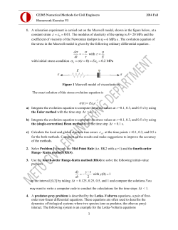


© Copyright 2026