
FPGA Implementation of Video Steganography
ISSN(Online): 2320-9801
ISSN (Print): 2320-9798
International Journal of Innovative Research in Computer and Communication Engineering
An ISO 3297: 2007 Certified Organization
Vol.3, Special Issue 3, April 2015
2nd National Conference On Emerging Trends In Electronics And Communication Engineering (NCETECE’15)
Organized by
Dept. of ECE, New Prince Shri Bhavani College Of Engineering & Technology, Chennai-600073, India during 6th & 7th April 2015
FPGA Implementation of Video
Steganography
Nancy Priya Grace.I1, Gowri Sankaran.B2
PG Scholar, VLSI Design, Department of Electronics and Communication Engineering, Sri Ramanujar Engineering
College, Chennai, Tamil Nadu, India1
Professor and Head, Department of Electronics and Communication Engineering, Sri Ramanujar Engineering College,
Chennai, Tamil Nadu, India2
ABSTRACT: Steganography techniques may be applied without fear of image destruction due to lossy compression
because they are more integrated into the image. Most of the work in this category has been concentrated on making
use of redundancies in the DCT (discrete cosine Transform) domain, which is used in JPEG compression. This paper
proposes LSB Information hiding algorithm which can lift wavelet transform image. The idea behind the LSB
algorithm is to insert the bits of the hidden message into the least significant bits of the pixels. Achieving the purpose of
information hiding with the secret bits of information to replace the random noise, using the lowest plane embedding
secret information to avoid noise and attacks, making use of redundancy to enhance the sound embedded in the way
nature to be addressed. The results showed that the proposed algorithm has a very good hidden invisibility, good
security and robustness for a lot of hidden attacks. However, the limitation of capacity has led us to think about an
improved approach which can be achieved through hardware implementation systems with the help of a field
programmable gate array (FPGA) board. It is the process of embedding data within the domain of another data, this
data can be text, image, and video contents. The embedded watermark can be invisible (hidden in such a way that it
cannot be retrieved without knowing the extraction algorithm) to the human eye.
KEYWORDS: DWT, LSB, Video Steganography
I.
INTRODUCTION
In present day, steganography has evolved into a digital strategy of hiding a file in some form of multimedia, such as an
image, an audio file (like a .wav or mp3) or even a video file [1].Stenographic systems can be divided into two
categories. In which one is very existence of the message is kept secret another non-steganography Systems, in which
the existence of the message need not be secret [2].The main goal of steganography is to communicate securely in a
completely undetectable manner and to avoid drawing suspicion to the transmission of a hidden data. That is not to
Information even exists. Steganography is of three types Audio, Image and Video.Through image steganography is the
more famous of the two, audio steganography is at present more secure due to the fact that the hackers do not suspect
the presence of a hidden message in a videos file.
II. STEGANOGRAPHY
Steganography means to hide secret information into innocent data Digital images are ideal for hiding secret
information. An image containing a secret message is called a cover image. First, the difference of the cover image and
the stego image should be visually unnoticeable. The embedding itself should draw no extra attention to the stego
image so that no hackers would try to extract the hidden message illegally. Second, the message hiding method should
be reliable. It is impossible for someone to extract the hidden message.
Copyright @ IJIRCCE
www.ijircce.com
47
ISSN(Online): 2320-9801
ISSN (Print): 2320-9798
International Journal of Innovative Research in Computer and Communication Engineering
An ISO 3297: 2007 Certified Organization
Vol.3, Special Issue 3, April 2015
2nd National Conference On Emerging Trends In Electronics And Communication Engineering (NCETECE’15)
Organized by
Dept. of ECE, New Prince Shri Bhavani College Of Engineering & Technology, Chennai-600073, India during 6th & 7th April 2015
A.
Stegosystem
The stegosystem is conceptually similar to the cryptosystem. Stegosystem image as shown in figure 1.
Fig 1.Stegosystem
emb: The message to be embedded. It is anything that can be represented as a bit stream (an image or text).
Cover: Data/Medium in which emb will be embedded.
Stego: Modified version of the cover that contains the embedded message.
emb.key: Additional data that is needed for embedding & extracting.
FE: Steganographic function that has cover, emb& key as parameters.
Here is a graphical version of the stegosystem shown in figure 2.
Fig 2. Graphical version of the Stegosystem
III. WAVELET TRANSFORM
Wavelets are mathematical functions defined over a finite interval and having an average value of zero that transform
data into different frequency components, representing each component with a resolution matched to its scale. The
basic idea of the wavelet transform is to represent any arbitrary function as a superposition of a set of such wavelets or
basis functions. These basis functions or baby wavelets are obtained from a single prototype wavelet called the mother
wavelet, by dilations or contractions (scaling) and translations (shifts). Many new wavelet applications such as image
compression, turbulence, human vision, radar, and earthquake prediction are developed in recent years. In wavelet
transform the basic functions are wavelets. All wavelet functions, w (2kt - m), are derived from a single mother wavelet,
w(t).
A.
Discrete Wavelet Transform
Calculating wavelet coefficients at every possible scale is a fair amount of work, and it generates an awful lot of data. If
the scales and positions are chosen based on powers of two, the so-called dyadic scales and positions, then calculating
wavelet coefficients are efficient and just as accurate. This is obtained from discrete wavelet transform (DWT). For
many signals, the low-frequency content is the most important part. It is the identity of the signal. The high-frequency
content, on the other hand, imparts details to the signal. In wavelet analysis, the approximations and details are obtained
after filtering. The approximations are the high-scale, low frequency components of the signal. The details are the lowscale, high frequency components.
Copyright @ IJIRCCE
www.ijircce.com
48
ISSN(Online): 2320-9801
ISSN (Print): 2320-9798
International Journal of Innovative Research in Computer and Communication Engineering
An ISO 3297: 2007 Certified Organization
Vol.3, Special Issue 3, April 2015
2nd National Conference On Emerging Trends In Electronics And Communication Engineering (NCETECE’15)
Organized by
Dept. of ECE, New Prince Shri Bhavani College Of Engineering & Technology, Chennai-600073, India during 6th & 7th April 2015
The original signal, S, passes through two complementary filters and emerges as two signals. Unfortunately, it
may result in doubling of samples and hence to avoid this, down sampling is introduced. The process on the right,
which includes down sampling, produces DWT coefficients. The schematic diagram with real signals inserted is as
shown in Figure 3.
Fig 3. Decomposition and decimation
B. Multiple-Level Decomposition
The decomposition process can be iterated, with successive approximations being decomposed in turn, so that one
signal is broken down into many lower resolution components. This is called the wavelet decomposition tree.
Fig 4. Multilevel decomposition
C.
1-D Wavelet Transforms
Here a signal is passed through a low pass and high pass filter, hand g, respectively, then down
sampled by a factor of two, constituting one level of transform.
Fig 5. 1D Wavelet Decomposition.
Repeating the filtering and decimation process on the low pass branch outputs make multiple levels or
“scales” of the wavelet transform only. The process is typically carried out for a finite number of levels K, and the
resulting coefficients are called wavelet coefficients.1D Wavelet decomposition representation shown in Figure 5.
The one-dimensional forward wavelet transform is defined by a pair of filters that are convolved with the data
at either the even or odd locations. The filters used for the forward transform are called analysis filters.
li
nL
s
j n1
j
X 2i j
And
hi
nH
t
j nH
j
X 2i1 j
(1)
The forward wavelet-based transform uses a 1-D sub band decomposition process; here a 1-D set of samples is
converted into the low-pass sub band (Li) and high-pass sub band (Hi). The low-pass sub band represents a down
Copyright @ IJIRCCE
www.ijircce.com
49
ISSN(Online): 2320-9801
ISSN (Print): 2320-9798
International Journal of Innovative Research in Computer and Communication Engineering
An ISO 3297: 2007 Certified Organization
Vol.3, Special Issue 3, April 2015
2nd National Conference On Emerging Trends In Electronics And Communication Engineering (NCETECE’15)
Organized by
Dept. of ECE, New Prince Shri Bhavani College Of Engineering & Technology, Chennai-600073, India during 6th & 7th April 2015
sampled low-resolution version of the original image. The high-pass sub band represents residual information of the
original image, needed for the perfect reconstruction of the original image from the low-pass sub band
D. 2-D Transform Hierarchy
The 1-D wavelet transform can be extended to a two-dimensional (2-D) wavelet transform using separable
wavelet filters. With separable filters the 2-D transform can be computed by applying a 1-D transform to all the rows of
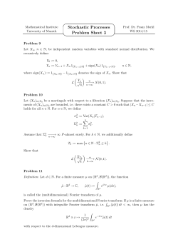
the input, and then repeating on all of the columns. Sub band Labeling Scheme for a one level, 2-D Wavelet Transform
The original image of a one-level (K=1), 2-D wavelet transform, with corresponding notation. The 2-D sub
band decomposition is just an extension of 1-D sub band decomposition. The entire process is carried out by executing
1-D sub band decomposition twice, first in one direction (horizontal), then in the orthogonal (vertical) direction. For
example, the low-pass sub bands (Li) resulting from the horizontal direction is further
decomposed in the vertical direction, leading to LLI and LHI sub bands as shown in Figure 6.
LL1
LH1
LH2
HL1
HH1
HL2
HL3
HH2
LH3
HH3
Fig 6. Sub band labeling Scheme for a Three Level, 2-D Wavelet Transform
Similarly, the high pass sub band (Hi) is further decomposed into HLI and HHI After one level of transform, the
image can be further decomposed by applying the 2-D sub band decomposition to the existing LLI sub band. The sub
band LLI is a low-resolution sub band and high-pass sub bands LHI, HLI, HHI are horizontal, vertical, and diagonal
sub band respectively since they represent the horizontal, vertical, and diagonal residual information of the original
image.
IV. AWIC FILTER CHOICE
The main difference between sub band and wavelet coding is the choice of filters to be used in the transform.
The filters used in wavelet coding systems were typically designed to satisfy certain smoothness constraints. In
contrast, sub band filters were designed to approximately satisfy the criteria of non-overlapping frequency responses.
There are two types of filter choices, orthogonal and orthogonal. The orthogonal wavelet transform has the advantage
that it can use linear phase filters, but the disadvantage is that it is not energy preserving. The fact that orthogonal
wavelets are not energy preserving does not turn out to be a big problem, since there are linear phase orthogonal filter
coefficients, which are “close” to being orthogonal.
The Haar sequence is now recognized as the first known wavelet basis and extensively used as a teaching
example. Haar wavelet is the simplest type of wavelet. It is conceptually simple. Reason to use haar filter: 1.It is fast.2.
It is memory efficient, since it can be calculated in place without a temporary Array.3. It is exactly reversible without
the edge effects that are a problem with other Wavelet transforms. The Haar wavelet is also the simplest possible
wavelet. The technical disadvantage of the Haar wavelet is that it is not continuous, and therefore not differentiable.
This property can, however, be an advantage for the analysis of signals with sudden transitions, such as monitoring of
tool failure in machines.
The Haar wavelet's mother wavelet function Ψ(t) can be described as
1 0 t 1/ 2
(t ) 1 1 / 2 t 1
0 Otherwise
Copyright @ IJIRCCE
(2)
www.ijircce.com
50
ISSN(Online): 2320-9801
ISSN (Print): 2320-9798
International Journal of Innovative Research in Computer and Communication Engineering
An ISO 3297: 2007 Certified Organization
Vol.3, Special Issue 3, April 2015
2nd National Conference On Emerging Trends In Electronics And Communication Engineering (NCETECE’15)
Organized by
Dept. of ECE, New Prince Shri Bhavani College Of Engineering & Technology, Chennai-600073, India during 6th & 7th April 2015
Its scaling function
1 0 t 1,
(t )
0 Otherwise
can be described as
(3)
A.
Algorithms and Transformations
Another Steganography method is to hide data in mathematical functions that are in compression algorithms. Two
functions are Discrete Cosine Transformation (DCT) and Wavelet Transformation. The DCT and wavelet functions
transform data from one domain into another. The DCT function transforms that data from a spatial domain to a
frequency domain.DCT transform as shown in Figure 7.
Fig 7. DCT Transform
The DCT function:
1
(u )(v) 7 7 (2i 1).u (2 j 1).v
F (u, v)
cos
. cos
. f (i, j ) where, ( ) 2
4 i 0 j 0
16
16
1
for 0
Otherwise
(4)
The idea behind it in regard to steganography is to hide the data bits in the least significant coefficients.
B. Steps of Data Hiding
1. Read the cover video signal and convert it into sequence of binary bits.
2. Read the Image to be embedded. Convert it into a sequence of binary bits say msg.
3. Apply DWT on video file.
4. Take higher frequency component as data
5. Generate a random key using the random key generator.
6. Segment binary audio into 8x8 sub blocks each with 16bits
7. Initiate textpos = 1;
8. For i=I: length (Data)
9. Data (i, 12:16) = msg (textpos, textpos+3);
10. Textpos = textpos+4;
11. End
12. Generate video file from Data.
C. Steps for Data Retrieval
1. Read the stego video signal.
2. Convert it into a sequence of binary bits.
3. Segment binary audio into 8x8 sub blocks each with16 bits.
4. Initiate tpos=l;
5. For i=l: length (Data)
6. .msg (pos, pos+3) = Data (i, 12:16);
7. Pos=pos+4;
8. End
9. The msg is the original message.
Copyright @ IJIRCCE
www.ijircce.com
51
ISSN(Online): 2320-9801
ISSN (Print): 2320-9798
International Journal of Innovative Research in Computer and Communication Engineering
An ISO 3297: 2007 Certified Organization
Vol.3, Special Issue 3, April 2015
2nd National Conference On Emerging Trends In Electronics And Communication Engineering (NCETECE’15)
Organized by
Dept. of ECE, New Prince Shri Bhavani College Of Engineering & Technology, Chennai-600073, India during 6th & 7th April 2015
D. Random Key Generation Algorithm
1. Take two initial values, say 0, 1.
2. An initial "carry bit", say O.
3. Repeat Step 4 until required number of Digits
4. The new digit can be calculated as
f ( ) = { (x" .... , Xr'Xr+l-s+ x, + c, 0) x" ..... ,xr,c (x" .... 'xr'xr+l-s+ x, + C - b, 1)
Where b is base (here b=lO).
E. Add With-Carry Generators
We introduce add-with-carry generators with a simple example. Consider the classical Fibonacci sequence. We take
each element the sum of the previous two. If we take this sequence mod 10, we have an example of a lagged-Fibonacci
sequence with lags r=2 and s= land binary operation. W - 17 + W modulo 0,1,2,2,3,5,8,3,1,4,5,9,4,3,7, ........ The
information description of the sequence is Xn= Xn-2 + xn_1modlO but to formally describe it and define andestablish
its period we need the finite set X of 1 x2 vectors x = (x" x2) with elements reduced residues of 10 and the iterating
function/defined by f = (x" x2) = (x2, x,+ mod m).
V. RESULTS
Steganography techniques may be applied without fear of image destruction due to lossy compression because they are
more integrated into the image. Most of the work in this category has been concentrated on making use of redundancies
in
the
DCT
(discrete
cosine Transform) domain, which is used in JPEG compression. But there have been other algorithms which make use
of other transform domains such as the frequency domain.
VI. CONCLUSION
This paper proposed LSB Information Hiding algorithm which can Lifting wavelet transform image. The idea behind
the LSB algorithm is to insert the bits of the hidden message into the least significant bits of the pixels. Achieving the
purpose of information hiding with the secret bits of information to replace the random noise, using the lowest plane
embedding secret information to avoid noise and attacks, making use of redundancy to enhance the sound embedded in
the way nature to be addressed. The results showed that the proposed algorithm has a very good hidden invisibility,
good security and robustness for a lot of hidden attacks.
VII.FUTURE ENHANCEMENT
The results showed that the proposed algorithm has a very good hidden invisibility, good security and robustness
for a lot of hidden attacks. However, the limitation of capacity has led us to think about an improved approach which
can be achieved through hardware implementation systems with the help of a programmable gate array (FPGA) board.
ACKNOWLEDGEMENT
The work on this paper was done by Nancy Priya Grace P.G Scholar, VLSI Design, Department of Electronics and
Communication Engineering Under the guidance of Mr.B.Gowri Sankaran Professor in the Department of Electronics
and Communication Engineering Sri Ramanujar Engineering College, Chennai.
REFERENCES
[1] A.Jain, “steganography: A solution for data Hiding”, Guru Nannak Dev. Engineering College, Ludhiana.
[2] S.Mazlee Na, R.K.Mohd, M.A Muhalim, and Subariah I. “Information Hiding Using Steganography”, Universities knologi Malaysia,2003.
[3] N.Cvejic, T.Seppben “Increasing the capacity of LSB-based audio Steganography” FIN-900 14 University of Oulu, Finland, 2002.
[4] S.Shiral i-Shahreza M.T. Mamzuri-Shalmani “High Capacity error free wavelet domain speech Steganography”ICASSP2008.
Copyright @ IJIRCCE
www.ijircce.com
52
ISSN(Online): 2320-9801
ISSN (Print): 2320-9798
International Journal of Innovative Research in Computer and Communication Engineering
An ISO 3297: 2007 Certified Organization
Vol.3, Special Issue 3, April 2015
2nd National Conference On Emerging Trends In Electronics And Communication Engineering (NCETECE’15)
Organized by
Dept. of ECE, New Prince Shri Bhavani College Of Engineering & Technology, Chennai-600073, India during 6th & 7th April 2015
[5] N.F.Johnson, Z.Duric and S.Jajodia “Information Hiding Steganography and watermarking-Attacks and Countermeasures”, Kluwer Academic
Publishers, 2001.
[6] M.Wu, B.Liu “Multimedia Data Hiding”, Springer-verlag New York, 2003
[7] W.Bender, D.Gruhl, N.Morimoto, A.Lu: Techniques for data hiding, IBM SYSTEMS JOURNAL, VOL 35, NO S3&4, 1996.
[8] N.F.Johnson.Steganography tools available from:
http://www.jjtc.com/security/stegtools.htm2005.
[9] M.M.Amin, M.salleh, S.Ibrahim, M.R.K.Atmin and M.Z.I. Shamsuddin “Information Hiding using Steganography” 4*National conference on
Telecommunication Proceedings, Shah Alam, Malaysia 2003 technology.
[10] A.Khireddine, K.Benamahammed and W.Puech, “Digital image restoration by wiener filter in 2D case”, Advance in Engineering Software,
Vol.38, No 7, pp.513-516, 2010.
[11] A.Ker, “Steganalysis of LSB Matching in Gray Scale Images”, IEEE signal processing Letter, VOl.12, pp.441-444, 2011.
[12] Q.Liu, A.Sung, Z.Chen, and J.Xu, “Image complexity and Features extraction for steaganalysis of LSB matching”, in proc.18 th Intl.conference
on pattern Recognition, Vol.2, 2009, pp.267-270.
[13] T.pevny and J.Fridrich, “ Merging markov and DCT features for multiclass JPEG steganalysis”, in proc. SPIE,
Electronic Imaging, Security, Steganography and water markingof multimedia contents IX, vol.6505, january2013,pp.03-04.
Copyright @ IJIRCCE
www.ijircce.com
53


© Copyright 2026