
On the radiation and diffraction of linear water waves by an infinitely
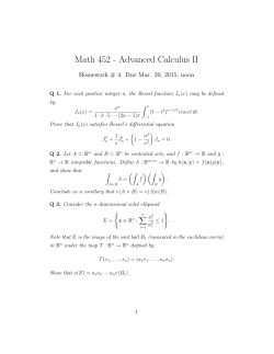
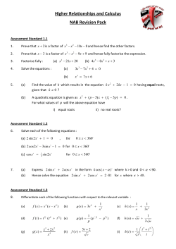
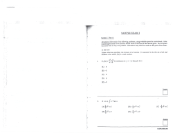
ARTICLE IN PRESS
Ocean Engineering 34 (2007) 436–450
www.elsevier.com/locate/oceaneng
On the radiation and diffraction of linear water waves by an infinitely
long rectangular structure submerged in oblique seas
Y.H. Zhenga,, P.F. Liua, Y.M. Shenb, B.J. Wua, S.W. Shenga
a
Guangzhou Institute of Energy Conversion, Chinese Academy of Sciences, Guangzhou 510640, People’s Republic of China
State Key Laboratory of Coastal and Offshore Engineering, Dalian University of Technology, Dalian 116023, People’s Republic of China
b
Received 20 June 2005; accepted 15 March 2006
Available online 27 June 2006
Abstract
The radiation and diffraction of linear water waves by an infinitely long rectangular structure submerged in oblique seas of finite depth
is investigated. The analytical expressions for the radiated and diffracted potentials are derived as infinite series by use of the method
of separation of variables. The unknown coefficients in the series are determined by the eigenfunction expansion matching method.
The expressions for wave forces, hydrodynamic coefficients and reflection and transmission coefficients are given and verified by the
boundary element method. Using the present analytical solution, the hydrodynamic influences of the angle of incidence, the
submergence, the width and the thickness of the structure on the wave forces, hydrodynamic coefficients, and reflection and transmission
coefficients are discussed in detail.
r 2006 Elsevier Ltd. All rights reserved.
Keywords: Oblique-wave radiation and diffraction; Analytical solution; Wave force; Hydrodynamic coefficient; Reflection and transmission coefficients
1. Introduction
There have been many theoretical and numerical studies
on the radiation and/or diffraction of oblique waves by
infinitely long structures. Levine (1965) studied the interaction of oblique waves with a completely submerged
circular cylinder near the free surface based on the Green’s
function. Garrison (1969) investigated the interaction of an
infinite shallow draft cylinder oscillating at the free surface
with a train of oblique waves using the boundary integral
method. Bolton and Ursell (1973) used the multipole
expansion method to the interaction of an infinitely long
circular cylinder with oblique waves. Bai (1975) presented a
finite-element method to study the diffraction of oblique
waves by an infinite cylinder in water of infinite depth. Liu
and Abbaspour (1982) studied the scattering of oblique
waves by an infinite cylinder of arbitrary shape using a
hybrid integral equation formulation. Leonard et al. (1983)
Corresponding author. Fax: +86 20 87057612.
E-mail address: [email protected] (Y.H. Zheng).
0029-8018/$ - see front matter r 2006 Elsevier Ltd. All rights reserved.
doi:10.1016/j.oceaneng.2006.03.002
extended Bai’s finite-element method to solve the diffraction and radiation boundary value problems arising from
multiple two-dimensional horizontal cylinders interacting
with obliquely incident linear waves. Garrison (1984) used
a Green’s function method to investigate the oblique-wave
interaction with a cylinder of arbitrary section on the free
surface in water of infinite depth. Isaacson and Nwogu
(1987) developed a generalized numerical procedure based
on Green’s theorem to compute the exciting forces and
hydrodynamic coefficients due to the interaction of oblique
waves with an infinitely long, semi-immersed floating
cylinder of arbitrary shape. Losada et al. (1992) and
Losada et al. (1993) applied the eigenfunction expansion
method to the propagation of oblique waves past rigid
vertical thin barriers and calculated the transmission and
reflection coefficients. Abul-Azm (1994) investigated the
diffraction through wide submerged breakwaters under
oblique waves by use of the eigenfunction expansion
method. Mandal and Dolai (1994, 1996) used the oneterm Galerkin approximation to determine the upper
and lower bounds for the reflection and transmission
ARTICLE IN PRESS
Y.H. Zheng et al. / Ocean Engineering 34 (2007) 436–450
coefficients in the problems of oblique-water wave diffraction by a thin vertical barrier in water of uniform finite
depth. The one-term Galerkin approximation was used
also by Das et al. (1997) to evaluate the upper and lower
bounds for the reflection and transmission coefficients in
the problem of oblique-water wave diffraction by two
equal thin, parallel, fixed vertical barriers with gaps
presented in water of uniform finite depth. Williams et al.
(1995) presented a Green’s function approach for oblique
wave diffraction by segmented offshore breakwaters.
Sannasiraj and Sundaravadivelu (1995) and Sannasiraj
et al. (2000) applied the finite-element technique to the
study of the interaction of oblique waves with one freely
floating long structure and with multiple floating structures
in directional waves, respectively. Abul-Azm and Williams
(1997) used the eigenfunction expansion method to
examine oblique-wave diffraction by a detached breakwater system consisting of an infinite row of regular-spaced
thin, impermeable structures located in water of uniform
depth. Cho et al. (1997, 1998), and Cho and Kim (1998)
investigated the performance of a single and dual flexible
membranes in oblique seas and the interaction of a
horizontal flexible membrane with oblique waves, respectively by use of the eigenfunction expansion method. The
method was used also more recently by Twu et al. (2002) to
examine the wave-damping characteristics of vertically
stratified porous structures under oblique-wave action.
Abul-Azm and Gesraha (2000) examined the hydrodynamic properties of a long rigid floating pontoon interacting with linear waves in water of finite depth by use of the
eigenfunction expansion method. Politis et al. (2002)
developed a boundary integral equation (BIE) method
for oblique-water wave scattering by cylinders in water of
infinite depth, and Zheng et al. (2006) studied analytically
the wave radiation by an infinitely long rectangular
structure floating on the free surface in oblique seas.
Although there are many analytical and numerical
studies on the interaction of oblique waves with twodimensional structures listed above, there were no analytical results, to the authors’ knowledge, reported on the
radiation and diffraction by an infinitely long rectangular
structure fully submerged in oblique seas. For this purpose,
the interaction of oblique waves with an infinitely long and
submerged rectangular structure is examined here by use of
an analytical method. The expressions for the radiated and
diffracted potentials are derived by use of the method of
separation of variables. The unknown coefficients in the
expressions are solved using the eigenfunction expansion
matching method. The expressions for wave exciting forces,
hydrodynamic coefficients, and reflection and transmission
coefficients are given, and verified through comparisons of
the results obtained by the present method with those by
the boundary element method (BEM). In addition, the
effects of the angle of incidence, the submergence, the
width and the thickness of the structure on wave forces,
hydrodynamic coefficients, and reflection and transmission
coefficients are discussed in detail.
437
2. Problem formulation and mathematical model
An infinitely long rectangular structure of width 2a,
submergence s1 and thickness b is submerged in water of
constant water depth h1. A linear wave train of amplitude
A and angular frequency o is obliquely incident upon the
structure from x ¼ p. A right-handed Cartesian coordinate system (x, y, z) shown in Fig. 1 is employed with
the origin at the undisturbed water surface. The z
coordinate is measured positive upwards and the x axis is
directed to the right. Here it is assumed that the structure is
infinite in direction y and the incident wave direction
makes an angle y (01oyo901) with the x-axis.
As usual we assume that the fluid is inviscid, incompressible, and the motion irrotational and periodic, so the
flow field can be depicted by a velocity potential
fðx; y; z; tÞ ¼ Re Fðx; y; zÞeiot , where p
Reffiffiffiffiffiffi[ffi ] denotes the
real part of a complex expression, i ¼ 1, t is the time
and F is the spatial complex velocity potential satisfying
the following three-dimensional Laplace equation:
q2 F q2 F q2 F
þ
þ 2 ¼ 0.
qx2 qy2
qz
(1)
For linear water waves, it is convenient to decompose F
into the following three parts:
F ¼ FI þ FD þ
3
X
FðRLÞ ,
(2)
L¼1
where FD and FðRLÞ (here L ¼ 1 stands for heave, 2 for sway
and 3 for roll) are the diffracted potential and the radiated
potential, respectively. FI is the incident wave potential
expressed as FI ¼ jI ðx; zÞ expðiky sin yÞ, where
jI ¼ igA cosh½kðz þ h1 Þ
expðikx cos yÞ,
o
coshðkh1 Þ
(3)
in which g is the gravitational acceleration and k is the
wave number, which is determined by the dispersion
relation k tanhðkh1 Þ ¼ o2 g.
2.1. Mathematical model for radiated potential
If we assume that the motions of the structure are small,
the oscillations vary sinusoidally in the y direction, and the
amplitude of motion mode L of the structure is denoted by
z
o
s1
y
x
IV
d1
b
h1
a
III
a
II
h2
Fig. 1. Schematic of geometry.
I
ARTICLE IN PRESS
Y.H. Zheng et al. / Ocean Engineering 34 (2007) 436–450
438
AðRLÞ , then the radiated potential FðRLÞ can be expressed as
FðRLÞ ¼ ioAðRLÞ jðRLÞ ðx; zÞ expðiky sin yÞ,
(4)
jðRLÞ
where
is the spatial potential independent of y.
Substitution of Eq. (4) into Eq. (1) yields the following
governing equation:
q2 jðRLÞ q2 jðRLÞ
þ
ðk sin yÞ2 jðRLÞ ¼ 0.
qx2
qz2
(5)
The boundary conditions for the radiation problem
considered are the following:
qjðRLÞ o2 ðLÞ
j ¼0
qz
g R
ðz ¼ 0Þ,
qjðRLÞ
¼ 0 ðz ¼ h1 Þ,
@z
qjðRLÞ
¼ d1;L ðx x0 Þd3;L
qz
ðz ¼ s1 or z ¼ d 1 ; jxjpaÞ,
(6)
(7)
3. Solution method
As usual the eigenfunction expansion matching method
is used here to obtain the analytical solution to the above
boundary-value problem. The fluid domain is divided into
four subdomains I, II, III and IV as indicated in Fig. 1. The
radiated potentials in the four subdomains are denoted by
LÞ
LÞ
LÞ
LÞ
, jðR2
, jðR3
and jðR4
and the diffracted potentials are
jðR1
denoted by jD1 , jD2 , jD3 and jD4 , respectively.
3.1. Expressions for radiated potentials
If the method of separation of variables is applied in
each subdomain shown in Fig. 1, one can obtain the
expressions for jðRLÞ as follows:
LÞ
jðR1
¼
/
X
Að1nLÞ egn ðxaÞ cos½ln ðz þ h1 Þ,
ð8Þ
qjðRLÞ
¼ d2;L þ ðz z0 Þd3;L ðd 1 pzp s1 ; x ¼ aÞ, (9)
qx
"
#
qjðRLÞ
ð LÞ
ik cos yjR ¼ 0,
lim
(10)
x!/
qx
where (x0, z0) is the assumed center of rotation and the d
function is given by
(
0 Laj;
(11)
dj;L ¼
1 L ¼ j:
LÞ
LÞ
jðR2
¼ jðR2P
þ
/ h
X
Að2nLÞ emn ðxþaÞ þ Bð2nLÞ emn ðxaÞ
n¼1
LÞ
¼
jðR3
/
X
ð18Þ
Að3nLÞ egn ðxþaÞ cos½ln ðz þ h1 Þ,
LÞ
LÞ
jðR4
¼ jðR4P
þ
/ h
X
Að4nLÞ eun ðxþaÞ þ Bð4nLÞ eun ðxaÞ
ð20Þ
where ln, an, gn, un, bn and mn are the eigenvalues expressed
by
n ¼ 1,
Similarly,
if
we
assume
FD ðx; y; zÞ ¼ jD ðx; zÞ
expðiky sin yÞ, then jD satisfies the following governing
equation and boundary conditions:
a1 ¼ ik1 ; k1 tanhðk1 s1 Þ ¼ o2 =g
qjD o2
j ¼0
qz
g D
(13)
qjD
¼ 0 ðz ¼ h1 Þ,
qz
qjD
qj
¼ I on S0 ,
qn
qn
qjD
ik cos y jD ¼ 0,
lim
x!/ qx
n ¼ 2; 3; . . . ,
(14)
(15)
bn ¼ ðn 1Þp=ðh1 d 1 Þ
where n is the outward normal from the fluid and S0 is the
wetted surface of the submerged rectangular cylinder.
n ¼ 1,
(22a)
(22b)
(23)
n ¼ 1;
(24)
n ¼ 2; 3; . . . ;
n ¼ 1; 2; 3; . . . ;
8
n ¼ 1;
< k0
qffiffiffiffiffiffiffiffiffiffiffiffiffiffiffiffi
mn ¼
2
2
: k0 þ bn n ¼ 2; 3; . . . ;
k0 ¼ k sin y
(21a)
(21b)
an tanðan s1 Þ ¼ o2 =g n ¼ 2; 3; . . . ,
8
< i k cos y n ¼ 1;
qffiffiffiffiffiffiffiffiffiffiffiffiffiffiffi
gn ¼
: l2n þ k20 n ¼ 2; 3; . . . ;
8 qffiffiffiffiffiffiffiffiffiffiffiffiffiffiffiffi
>
< i k21 k20
un ¼ qffiffiffiffiffiffiffiffiffiffiffiffiffiffiffi
>
: a2n þ k20
(16)
i
n¼1
cos½an ðz þ s1 Þ
ln tanðln h1 Þ ¼ o2 =g
(12)
(19)
n¼1
2.2. Mathematical model for diffracted potential
q2 jD q2 jD
þ
ðk sin yÞ2 jD ¼ 0,
qx2
qz2
i
cos bn ðz þ h1 Þ
l1 ¼ ik; k tanhðkh1 Þ ¼ o2 =g
ðz ¼ 0Þ,
(17)
n¼1
(25)
(26)
(27)
ARTICLE IN PRESS
Y.H. Zheng et al. / Ocean Engineering 34 (2007) 436–450
LÞ
LÞ
and jðR2P
and jðR4P
are the particular solutions for
radiation motion mode L in subdomain II and IV
respectively, their expressions are given by
LÞ
jðR2P
(28)
¼ C F 2 ðzÞ d1;L ðx x0 Þd3;L ,
LÞ
jðR4P
¼ C F 4 ðzÞ d1;L ðx x0 Þd3;L ,
(29)
where
k0
sinhðk0 zÞ þ k0 coshðk0 zÞ
o2
g
coshðk0 s1 Þ k0 sinhðk0 s1 Þ
h
n¼1
jD3 ¼
/
X
i.
(31)
ð33Þ
A03n egn ðxþaÞ cos½ln ðz þ h1 Þ,
(34)
n¼1
/ X
A04n eun ðxþaÞ þ B04n eun ðxaÞ
n¼1
(30)
o2
g
/ X
A02n emn ðxþaÞ þ B02n emn ðxaÞ
cos bn ðz þ h1 Þ
jD4 ¼ jI þ
cosh m1 ðz þ h1 Þ
,
C F 2 ð zÞ ¼
m1 sinh m1 h2
C F 4 ð zÞ ¼
jD2 ¼ jI þ
439
cos½an ðz þ s1 Þ
ð35Þ
where ln, an, gn, un, bn and mn are the eigenvalues expressed
by Eqs. (21)–(26), respectively.
3.3. Solution method for the unknown coefficients
3.2. Expressions for diffracted potentials
The unknown coefficients Að1nLÞ , Að2nLÞ , Að3nLÞ , Að4nLÞ , Bð2nLÞ , Bð4nLÞ ,
A02n , A03n , A04n , B02n and B04n ðn ¼ 1; 2; 3; . . . ; L ¼ 1; 2; 3Þ
appearing in Eqs. (17)–(20) and Eqs. (32)–(35) are
determined by the eigenfunction expansion matching
method using the conditions of continuity of pressure
A01n ,
jD1 ¼
/
X
A01n egn ðxaÞ cos½ln ðz þ h1 Þ,
(32)
0.8
-2.8
0.6
-2.9
0.4
-3.0
1
F1
n¼1
-3.1
0.2
0.0
-3.2
0
3
(a)
6
kh1
9
12
0
3
6
kh1
9
12
0
3
6
kh1
9
12
0
3
6
kh1
9
12
(b)
-1.4
0.4
0.2
2
F2
0.3
-1.5
0.1
0.0
-1.6
0
3
(c)
6
kh1
9
12
(d)
1.75
0.8
1.70
0.4
3
F3
0.6
1.65
0.2
0.0
(e)
1.60
0
3
6
kh1
9
12
(f)
Fig. 2. Dimensionless wave forces and phase angle by present method and by BEM (s1/h1 ¼ 0.2, b/h1 ¼ 0.2, h1/a ¼ 6, y ¼ 301, (x0/h1, z0/h1 ¼ (0, 0)). ––––
present method; , BEM.
ARTICLE IN PRESS
Y.H. Zheng et al. / Ocean Engineering 34 (2007) 436–450
440
and normal velocity at x ¼ 7a. For the radiation problem,
the continuity conditions are the following:
8 ðL Þ
qjR4
>
>
>
s1 ozo0; x ¼ a;
>
>
LÞ
< qx
qjðR1
¼ d2;L þ ðz z0 Þd3;L d 1 ozo s1 ; x ¼ a;
>
qx
>
>
qjðLÞ
>
>
: R2
h1 ozo d 1 ; x ¼ a;
qx
(36)
8 ðL Þ
qjR4
>
>
>
>
>
LÞ
< qx
qjðR3
¼ d2;L þ ðz z0 Þd3;L
>
qx
>
>
qjðLÞ
>
>
: R2
qx
s1 ozo0; x ¼ a;
d 1 ozo s1 ; x ¼ a;
h1 ozo d 1 ; x ¼ a;
(37)
LÞ
LÞ
jðR2
¼ jðR1
h1 pzp d 1 ; x ¼ a,
LÞ
LÞ
¼ jðR3
jðR4
s1 pzp0; x ¼ a,
(41)
while for the diffraction problem, the conditions of
continuity are expressed as
8
qjD4
>
>
x ¼ a; s1 ozo0;
> qx
>
>
>
qjD1 < qjI
x ¼ a; d 1 ozo s1 ;
(42)
¼ qx
>
qx
>
>
>
qj
>
>
: D2 x ¼ a; h1 ozo d 1 ;
qx
8
qjD4
>
>
>
>
>
> qx
qjD3 < qjI
¼ qx
>
qx
>
>
>
qjD2
>
>
:
qx
x ¼ a; s1 ozo0;
x ¼ a; d 1 ozo s1 ;
(43)
x ¼ a; h1 ozo d 1 ;
(38)
jD2 ¼ jD1
x ¼ a; h1 pzp d 1 ,
(44)
h1 pzp d 1 ; x ¼ a,
(39)
jD2 ¼ jD3
x ¼ a; h1 pzp d 1 ,
(45)
LÞ
LÞ
jðR4
¼ jðR1
s1 pzp0; x ¼ a,
(40)
jD4 ¼ jD1
x ¼ a; s1 pzp0,
(46)
1.2
0.4
1.0
0.3
Cd1
Ca1
LÞ
LÞ
jðR2
¼ jðR3
0.8
0.6
0.2
0.1
0.4
0.0
0
3
(a)
6
kh1
9
12
0
3
6
kh1
9
12
0
3
6
kh1
9
12
0
3
6
kh1
9
12
(b)
0.15
0.4
0.10
Cd2
Ca2
0.5
0.05
0.3
0.00
0.2
0
3
(c)
6
kh1
9
12
(d)
1.8
0.6
1.5
Cd3
Ca3
0.4
1.2
0.2
0.9
0.6
0.0
0
(e)
3
6
kh1
9
12
(f)
Fig. 3. Dimensionless hydrodynamic coefficients by present method and by BEM (s1/h1 ¼ 0.2, b/h1 ¼ 0.2, h1/a ¼ 6, y ¼ 301, (x0/h1, z0/h1 ¼ (0, 0)). ––––,
present method; , BEM.
ARTICLE IN PRESS
Y.H. Zheng et al. / Ocean Engineering 34 (2007) 436–450
jD4 ¼ jD3
x ¼ a; s1 pzp0.
(47)
According to the method presented in Zheng et al.
(2004), if the first N terms in all infinite series are taken, one
can obtain the following two sets of linear system of
complex equations:
SXðRLÞ ¼ FðLÞR ,
(48a)
SXD ¼ FD ,
(48b)
where S is the 6N 6N coefficient matrix of the system;
F(L)R and FD are the right-hand side vectors of length 6N.
441
XðRLÞ and XD are the vectors of the unknown coefficients in
the expressions for the radiated and diffracted potentials,
respectively.
X D ¼ ½A011 ; . . . ; A01N ; A021 ; . . . ; A02N ; A031 ; . . . ;
0
0
0
A3N ; A41 ; . . . ; A4N ; B021 ; . . . ; B02N ; B041 ; . . . ; B04N T and the
same order is applied to the arrangement of the unknown
coefficients in XðRLÞ . For convenience to readers, the
expressions for the non-zero elements in S, F(L)R and FD
are given in Appendix A.
Eq. (48) can be solved by a standard solution method for
a linear system of equations. After the unknown coefficients are determined, the wave forces, hydrodynamic
coefficients, and transmission and reflection coefficients
can be calculated.
0.8
-2.2
0.6
-2.4
1
F1
-2.6
0.4
-2.8
0.2
-3.0
0.0
-3.2
0
3
(a)
6
kh1
9
12
0
3
6
kh1
9
12
0
3
6
kh1
9
12
0
3
6
kh1
9
12
0
3
6
kh1
9
12
(b)
0.5
-1.3
0.4
-1.4
2
F2
0.3
0.2
-1.5
0.1
0.0
0
3
(c)
6
kh1
9
-1.6
12
(d)
0.8
1.8
1.7
0.4
3
F3
0.6
1.6
0.2
0.0
1.5
0
3
9
12
(f)
0.8
1.0
0.6
0.9
Tw
Rw
(e)
6
kh1
0.4
0.2
0.7
0.0
0.6
0
(g)
0.8
3
6
kh1
9
12
(h)
Fig. 4. Effect of angle of incidence on dimensionless wave forces and reflection and transmission coefficients (s1/h1 ¼ 0.2, b/h1 ¼ 0.2, h1/a ¼ 6, (x0/h1,
z0/h1 ¼ (0, 0)). –––– y ¼ 151; –––– y ¼ 451; ––’–– y ¼ 751.
ARTICLE IN PRESS
Y.H. Zheng et al. / Ocean Engineering 34 (2007) 436–450
442
4. Expressions for wave forces and hydrodynamic
coefficients
4.1. Expressions for wave forces
Because the structure is assumed infinite and the velocity
potential is assumed periodic in the y direction, only
the wave forces acting on a cross-section perpendicular to
the y axis is considered here. The wave
force in direction
j
can be expressed as F jyt ¼ Re F wj eiðky sin yotÞ where
Fwj is the wave force independent of y and time t, and
can be calculated from the incident and diffracted
potentials by
Z
F wj ¼ rio
jI þ jD nj ds
(49)
S0
or from the incident and radiated potentials by
Z
Z
ð j Þ qjI
ds ,
F wj ¼ rio
jI nj ds jR
qn
S0
S0
components of unit inward normal to the surface of the
structure.
Substituting Eqs. (3), (17)–(20) and (32)–(35) into
Eqs. (49) and (50), one can easily obtain the specific
expressions for wave forces by using the diffracted and
radiated potentials, respectively. For convenience to a
reader, the specific expressions for the wave excitation
forces by using the incident and diffracted potentials are
given in Appendix B.
4.2. Expressions for hydrodynamic coefficients
As presented in Zheng et al. (2006), the hydrodynamic
coefficients including the added mass mL,j and the damping
coefficient NL,j are defined here by
Z
h
i
mL;j ¼ r
Re jðRLÞ nj ds ¼ r Re f L;j ,
(51a)
S0
(50)
in which r is the density of water, S0 is the wetted surface
of the structure in the xz plane, nj is the generalized inward
normal to the structure in the xz plane with n1 ¼ nz,
n2 ¼ nx and n3 ¼ ðz z0 Þnx ðx x0 Þnz , nx and nz are the
Z
N L;j ¼ ro
S0
(51b)
where the expressions for f L;j ðL ¼ 1; 2; 3; j ¼ 1; 2; 3Þ are
given in Appendix C.
1.2
0.6
0.8
0.4
Cd1
Ca1
h
i
Im jðRLÞ nj ds ¼ roIm f L;j ,
0.2
0.4
0.0
0.0
0
3
(a)
6
kh1
9
0
12
3
6
9
12
kh1
(b)
0.15
0.5
Cd2
Ca2
0.10
0.3
0.05
0.00
0.1
0
3
(c)
6
kh1
9
12
0
3
6
kh1
9
12
0
3
6
kh1
9
12
(d)
2.0
1.5
Cd3
Ca3
0.4
1.0
0.2
0.5
0.0
0
(e)
3
6
kh1
9
12
(f)
Fig. 5. Effect of angle of incidence on hydrodynamic coefficients (s1/h1 ¼ 0.2, b/h1 ¼ 0.2, h1/a ¼ 6, (x0/h1, z0/h1 ¼ (0, 0)). –––– y ¼ 151; –––– y ¼ 451;
––’–– y ¼ 751.
ARTICLE IN PRESS
Y.H. Zheng et al. / Ocean Engineering 34 (2007) 436–450
443
4.3. Expressions for reflection and transmission coefficients
5. Results and discussion
When the structure is assumed stationary, the reflection
coefficient Rw and the transmission coefficient Tw can be
calculated by the following expressions:
5.1. Verification of the analytical solution
ioA0 coshðkh1 Þ
31
,
Rw ¼
gA
(52)
(
ioA011 coshðkh1 Þ
T w ¼ 1 þ
.
gAeika cos y (53)
C aj ¼
0.8
-2.8
0.6
-2.9
0.4
-3.0
1
F1
In this section, BEM is used to verify the present analytical
solution. The geometric parameters for the computation
are
s1 =h1 ¼ 0:2, b=h1 ¼ 0:2, h1 =a ¼ 6, y ¼ 301 and x0 =h1 ;
z0 =h1 Þ ¼ ð0; 0Þ. The results calculated by use of the present
analytical expressions and by BEM are given in Figs. 2 and 3,
where all quantities are non-dimensionalized as follows:
j ¼ 1; 2;
mj;j ð2rad 1 Þ
3
mj;j 2ra d 1 j ¼ 3;
-3.1
0.2
-3.2
0.0
0
3
6
kh1
(a)
9
12
0
3
6
kh1
9
12
0
3
6
kh1
9
12
0
3
6
kh1
9
12
0
3
6
kh1
9
12
(b)
0.4
-1.4
0.2
2
F2
0.3
-1.5
0.1
0.0
-1.6
0
3
6
kh1
(c)
9
12
(d)
1.8
1.2
hc
1.7
0.6
3
F3
0.9
1.6
0.3
1.5
0.0
0
3
(e)
6
kh1
9
12
(f)
1.00
0.20
0.10
Tw
Rw
0.15
0.99
0.05
0.98
0.00
0
(g)
3
6
kh1
9
12
(h)
Fig. 6. Effect of the submergence on the dimensionless wave forces and reflection and transmission coefficients. (b/h1 ¼ 0.2, h1/a ¼ 6, y ¼ 301, (x0/h1,
z0/h1 ¼ (0, 0)). ––––, s1/h1 ¼ 0.2; ––––, s1/h1 ¼ 0.4; ––’––, s1/h1 ¼ 0.6.
ARTICLE IN PRESS
Y.H. Zheng et al. / Ocean Engineering 34 (2007) 436–450
444
(
C dj ¼
N j;j ð2road 1 Þ
N j;j 2roa3 d 1
( F wj ð2rgAaÞ
F j ¼ F wj 2rgAa2
not necessarily valid for the corresponding dimensional
quantities. The computational parameters used are almost
the same as those presented in Section 5.1 and only one
parameter is changed for a particular case. The emphases
of the discussions are laid on the hydrodynamic effects of
the angle of incidence, the submergence, the thickness and
the width of the structure on wave forces, hydrodynamic
coefficients, and reflection and transmission coefficients.
j ¼ 1; 2;
j ¼ 3;
j ¼ 1; 2;
j ¼ 3;
yj ¼ tan1 Im F wj Re F wj .
Fig. 2 shows the dimensionless wave forces and their phase
angles, and Fig. 3 gives the dimensionless added mass and
damping coefficients obtained by the present method and by
BEM. Clearly, the results obtained by the present method
agree very well with those obtained by BEM, which illustrates
that the analytical expressions for the diffracted and radiated
potentials, wave forces and hydrodynamic coefficients are
correct.
5.2. Discussions
1.2
0.4
0.9
0.3
Cd1
Ca1
The discussions presented in this section are based on the
dimensionless quantities defined in Section 5.1, and the
obtained rules are valid only for dimensionless quantities,
5.2.1. Hydrodynamic effects of angle of wave incidence
To illustrate the hydrodynamic effects of the angle of
wave incidence, we compute the wave forces, hydrodynamic coefficients, and reflection and transmission coefficients for the angle of incidence y ¼ 151, 451 and 751. The
results are given in Figs. 4 and 5. It can be seen that the
influences of the angle of incidence on the dimensionless
wave forces, hydrodynamic coefficients, and reflection and
transmission coefficients are appreciable in some water
region. For the example given here, as the angle of
incidence increases, the dimensionless wave excitation
forces F1, F2, and F3, the transmission coefficient Tw, the
dimensionless heave added mass Ca1, and the dimensionless sway and roll damping coefficients Cd2 and Cd3
0.6
0.1
0.3
0.0
0.0
0
3
6
9
12
0
3
(b)
kh1
(a)
6
9
12
9
12
9
12
kh1
0.15
0.5
0.4
0.10
Cd2
Ca2
0.2
0.3
0.05
0.2
0.00
0.1
0
3
(c)
6
kh1
9
12
0
3
(d)
4.5
6
kh1
0.6
3.5
Cd3
Ca3
0.4
2.5
0.2
1.5
0.5
0.0
0
(e)
3
6
kh1
9
12
0
(f)
3
6
kh1
Fig. 7. Effect of the submergence on the dimensionless hydrodynamic coefficients. (b/h1 ¼ 0.2, h1/a ¼ 6, y ¼ 301, (x0/h1, z0/h1 ¼ (0, 0)). ––––, s1/h1 ¼ 0.2;
––––, s1/h1 ¼ 0.4; ––’––, s1/h1 ¼ 0.6.
ARTICLE IN PRESS
Y.H. Zheng et al. / Ocean Engineering 34 (2007) 436–450
decrease, while the reflection coefficient Rw and the
dimensionless heave damping coefficient Cd1 increase.
The dimensionless sway added mass Ca2 and roll added
mass Ca3 increase in some water region (e.g. kh1 o5), while
they decrease in the water region of kh1 47 with the
increase in the angle of wave incidence.
5.2.2. Hydrodynamic effect of the submergence of the
structure
The hydrodynamic influences of the submergence of the
structure on the hydrodynamic behaviour of the structure
are shown in Figs. 6 and 7 for s1/h1 ¼ 0.2, 0.4 and 0.6. It
can be seen from Fig. 6 that the dimensionless vertical and
horizontal forces and the reflection coefficients decrease
with increase in the submergence ratio s1/h1. The roll
torque increases in the water region of kh1 ohc and
decreases in the water region of kh1 ohc as the submergence
ratio increases. Fig. 7 illustrates that the larger the
submergence ratio s1/h1, the smaller the dimensionless
hydrodynamic coefficients for the structure in heave and
sway motions and the larger the roll added mass.
5.2.3. Hydrodynamic effect of the width and thickness of the
structure
Figs. 8 and 9 show the influences of the width of the
structure on the dimensionless wave forces, hydrodynamic
2.0
1.2
0.9
0.0
1
F1
445
0.6
-2.0
0.3
-4.0
0.0
0
3
(a)
6
kh1
9
12
6
kh1
9
12
0
3
6
kh1
9
12
0
3
6
kh1
9
12
0
3
6
kh1
9
12
1.0
0.2
2
F2
0.3
-1.0
0.1
-3.0
0.0
0
3
(c)
6
kh1
9
12
(d)
3.0
0.4
1.0
F3
3
0.6
-1.0
0.2
-3.0
0.0
0
3
(e)
6
kh1
9
12
(f)
1.0
0.8
0.6
0.9
Tw
Rw
3
3.0
0.4
0.4
0.8
0.2
0.7
0.0
0
(g)
0
(b)
3
6
kh1
9
12
(h)
Fig. 8. Effect of the width on the dimensionless wave forces and reflection and transmission coefficients. (s1/h1 ¼ 0.2, b/h1 ¼ 0.2, y ¼ 301, (x0/h1,
z0/h1 ¼ (0, 0)). ––––, a/h1 ¼ 0.2; ––––, a/h1 ¼ 0.4; ––’––, a/h1 ¼ 0.6.
ARTICLE IN PRESS
Y.H. Zheng et al. / Ocean Engineering 34 (2007) 436–450
446
coefficients, and reflection and transmission coefficients for
a/h1 ¼ 0.2, 0.4 and 0.6. Clearly, the influences of the width
on the hydrodynamic behaviors are appreciable, especially
the influences on the reflection and transmission coefficients. The maximum reflection coefficient and the minimum transmission coefficient, regarded as a function of
kh1, greatly increase and decrease, respectively, with the
increase of the width ratio a/h1. This should be seriously
considered when a rectangular structure is used as a
submerged breakwater in oblique seas.
Fig. 10 illustrates the influences of the thickness of the
structure on the dimensionless wave forces and reflection
and transmission coefficients. Clearly the influence of the
thickness on the dimensionless vertical force is relatively
small, and the dimensionless horizontal force and transmission coefficient increase with the increase of the thickness
ratio b/h1. The effects of the thickness of the structure on
the dimensionless hydrodynamic coefficients are presented
in Fig. 11. It can be seen that the dimensionless added
masses and damping coefficients of heave motions
decrease, while those of sway motions increase as the
thickness ratio increases.
6. Concluding remarks
The radiation and diffraction problem arising from the
interaction of linear water waves with an infinitely long
submerged rectangular structure in oblique seas is studied
here by use of the method of separation of variables and
the eigenfunction expansion matching method. The analytical expressions for the radiated and diffracted potentials,
wave forces, hydrodynamic coefficients, and the reflection
and transmission coefficients are given and verified. The
effects of the angle of incidence, the submergence, the
width and the thickness of the structure on wave forces,
hydrodynamic coefficients and reflection and transmission
coefficients are examined, which may provide some
important information for engineering designers.
Acknowledgments
This work is supported by the National Basic Research
Program of China under Grant no. 2005CB724202, the
National Natural Science Foundation of China under
6.0
4.0
3.0
Cd1
Ca1
4.0
2.0
2.0
1.0
0.0
0.0
0
3
(a)
6
kh1
9
12
0
3
6
kh1
9
12
0
3
6
kh1
9
12
0
3
6
kh1
9
12
(b)
0.6
0.20
0.15
Cd2
Ca2
0.4
0.10
0.2
0.05
0.0
0.00
0
3
6
kh1
9
12
(d)
(c)
0.8
0.4
Cd3
0.6
Ca3
1.2
0.2
0.4
0.0
0.0
0
(e)
3
6
kh1
9
12
(f)
Fig. 9. Effect of the width on the dimensionless hydrodynamic coefficients (s1/h1 ¼ 0.2, b/h1 ¼ 0.2, y ¼ 301, (x0/h1, z0/h1 ¼ (0, 0)). ––––, a/h1 ¼ 0.2; ––––,
a/h1 ¼ 0.4; ––’––, a/h1 ¼ 0.6.
ARTICLE IN PRESS
Y.H. Zheng et al. / Ocean Engineering 34 (2007) 436–450
2.0
1.0
0.0
F1
1
1.5
-2.0
0.5
-4.0
0.0
0
3
(a)
6
kh1
9
12
3.0
0.4
1.0
3
6
kh1
9
12
0
3
6
kh1
9
12
0
3
6
kh1
9
12
0
3
6
kh1
9
12
2
F2
0.6
-1.0
-3.0
0.0
0
3
(c)
6
kh1
9
12
(d)
3.0
0.4
1.0
F3
3
0.6
-1.0
0.2
0.0
-3.0
0
3
(e)
6
kh1
9
12
(f)
0.8
1.0
0.6
0.9
0.4
0.8
Tw
Rw
0
(b)
0.2
0.7
0.2
0.0
(g)
447
0.6
0
3
6
kh1
9
12
(h)
Fig. 10. Effect of the thickness on the dimensionless wave forces and reflection and transmission coefficients (s1/h1 ¼ 0.2, a/h1 ¼ 0.6, y ¼ 301, (x0/h1,
z0/h1 ¼ (0, 0)). ––––, b/h1 ¼ 0.1; ––––, b/h1 ¼ 0.2; ––’––, b/h1 ¼ 0.4.
Grant nos. 50579005 and 10332050, and the Guangdong
Natural Science foundation under Grant no. 04000377.
Appendix A. Expressions for the non-zero elements in S,
F(L)R and FD
(L)R
The expressions for the non-zero elements in S, F
and
FD are given as follows ði ¼ 1; 2; . . . ; N; j ¼ 1; 2; . . . ; N Þ:
S i;i ¼ gi N ðli Þ; Si;Nþj ¼ mj e2mj a E li ; bj ,
S i;3Nþj ¼ uj e2uj a F li ; aj ,
Si;4Nþj ¼ mj E li ; bj ; S i;5Nþj ¼ uj F li ; aj ,
SNþi;2Nþi ¼ gi N ðli Þ,
SNþi;Nþj ¼ mj E li ; bj ; S Nþi;3Nþj ¼ uj F li ; aj ,
SNþi;4Nþj ¼ mj e2mj a E li ; bj ,
SNþi;5Nþj ¼ uj e2uj a F li ; aj ,
S2Nþi;j ¼ E lj ; bi ; S2Nþi;Nþi ¼ N bi e2mi a ,
S2Nþi;4Nþi ¼ N bi ; S3Nþi;2Nþj ¼ E lj ; bi ,
S3Nþi;Nþi ¼ N bi ,
ARTICLE IN PRESS
Y.H. Zheng et al. / Ocean Engineering 34 (2007) 436–450
448
6.0
8.0
4.0
Cd1
Ca1
6.0
4.0
2.0
2.0
0.0
0.0
0
3
9
12
0
3
6
kh1
9
12
0
3
6
kh1
9
12
0
3
6
kh1
9
12
(b)
0.8
0.4
0.6
0.3
Cd2
Ca2
(a)
6
kh1
0.4
0.2
0.1
0.2
0.0
0.0
0
3
6
kh1
9
12
(c)
(d)
0.6
0.9
0.7
Cd3
Ca3
0.4
0.5
0.3
0.2
0.1
-0.1
0.0
0
3
(e)
6
kh1
9
12
(f)
Fig. 11. Effect of the thickness on the dimensionless hydrodynamic coefficients. (s1/h1 ¼ 0.2, a/h1 ¼ 0.6, y ¼ 301, (x0/h1, z0/h1 ¼ (0, 0)). ––––, b/h1 ¼ 0.1;
––––, b/h1 ¼ 0.2; ––’––, b/h1 ¼ 0.4.
S 3Nþi;4Nþi ¼ N bi e2mi a ; S 4Nþi;j ¼ F lj ; ai ,
S 4Nþi;3Nþi ¼ N ðai Þe
2ui a
,
S 5Nþi;3Nþi ¼ N ðai Þ,
¼
Pð3iLÞ ,
LÞ
F ðR4Nþi
Pð5iLÞ ,
F Di ¼
LÞ
¼ Pð4iLÞ ; F ðR5Nþi
¼
ika cos y
P6i e
; F DNþi
¼ P6i eika cos y ,
¼
LÞ
F ðR3Nþi
E li ; bj ¼
F li ; aj ¼
Pð1iLÞ ¼ where
cos2 ½li ðz þ h1 Þ dz,
Z
h1
N bi ¼
cos½li ðz þ h1 Þ cos bj ðz þ h1 Þ dz,
Z
0
cos½li ðz þ h1 Þ cos aj ðz þ s1 Þ dz,
Z
d 1
C F 2 ðzÞ cos½li ðz þ h1 Þd3;L dz
h1
Z 0
d 1
0
Z
d 1
C F 4 ðzÞ cos½li ðz þ h1 Þ d3;L dz
s1
Z s1
þ
d2;L þ ðz z0 Þd3;L cos½li ðz þ h1 Þ dz,
F D4Nþi ¼ P8i eika cos y ; F D5Nþi ¼ P8i eika cos y ,
Z
Z
s1
F D2Nþi ¼ P7i eika cos y ; F D3Nþi ¼ P7i eika cos y ,
N ð li Þ ¼
cos2 ½ai ðz þ s1 Þ dz;
h1
LÞ
S 5Nþi;5Nþi ¼ N ðai Þe2ui a ; F ðRiLÞ ¼ F ðRNþi
¼ Pð1iLÞ ,
Pð2iLÞ ;
0
N ð ai Þ ¼
s1
S 4Nþi;5Nþi ¼ N ðai Þ; S 5Nþi;2Nþj ¼ F lj ; ai ,
LÞ
F ðR2Nþi
Z
d 1
h1
cos2 bi ðz þ h1 Þ dz,
Pð2iLÞ
¼
C F 2 ðzÞ d1;L ða x0 Þd3;L
h1
cos bi ðz þ h1 Þ dz,
d 1
ARTICLE IN PRESS
Y.H. Zheng et al. / Ocean Engineering 34 (2007) 436–450
Pð3iLÞ ¼
Pð4iLÞ
Z
d 1
Z
0
C F 2 ðzÞ d1;L þ ða þ x0 Þd3;L
h1
cos bi ðz þ h1 Þ dz,
C k ðnÞ ¼
C F 4 ðzÞ d1;L ða x0 Þd3;L
¼
a e2mn a þ 1
e2mn a 1
C b1 ðnÞ ¼ cos bn h2
,
mn
m2n
s1
Pð5iLÞ ¼
d 1
a e2un a þ 1
e2un a 1
C a1 ðnÞ ¼
.
u2n
un
C F 4 ðzÞ d1;L þ ða þ x0 Þd3;L
h1
cos½ai ðz þ s1 Þ dz,
Appendix C. Expressions for fL,1, fL,2 and fL,3
8
h
i
< gkA cos y h1 þ sinhð2kh1 Þ
4k
o coshðkh1 Þ 2
P6i ¼
:
0
P7i ¼
P8i ¼
ðs1 þ z0 Þ sinðln h3 Þ þ ðd 1 þ z0 Þ sinðln h2 Þ
ln
cosðln h3 Þ cosðln h2 Þ
þ
,
l2n
cos½ai ðz þ s1 Þ dz,
Z
449
The expressions for fL,1, fL,2 and fL,3 (L ¼ 1, 2 ,3) are
given as follows:
/ h
i
X
f L;1 ¼ f PL;1 þ
Að2nLÞ þ Bð2nLÞ C b ðnÞ,
i ¼ 1;
ia1;
igA
ð1Þi1 k sinhðkh2 Þ
,
o coshðkh1 Þ
k2 þ b2i
igA
o coshðkh1 Þ
Z
n¼1
/ h
X
i
Að4nLÞ þ Bð4nLÞ C a ðnÞ,
n¼1
0
cosh½kðz þ h1 Þ cos½ai ðz þ s1 Þ.
s1
f L;2 ¼
/
X
h
i
C l ðnÞ Að3nLÞ Að1nLÞ ,
n¼1
Appendix B. Expressions for wave excitation forces
The expressions for the vertical forces Fw1, the horizontal
force Fw2 and the torque Fw3 by using the diffracted
potentials are expressed as follows:
"
#
/ X
0
0
0
0
A2n þ B2n C b ðnÞ A4n þ B4n C a ðnÞ ,
F w1 ¼ rio
f L;3 ¼ f PL;3 þ
þ
/ X
rgAC y C l ð1Þ
þ rio
¼
A03n A01n C l ðnÞ,
coshðkh1 Þ
n¼1
"
F w3 ¼ rio
/ X
þ x0
A02n þ B02n C b ðnÞ þ
n¼1
x0
#
n¼1
/ X
A04n B04n C a1 ðnÞ
n¼1
/ X
rgAC y C k ð1Þ
,
A04n þ B04n C a ðnÞ þ
coshðkh1 Þ
n¼1
where
C b ðnÞ ¼ cos bn h2 e2mn a 1 mn ,
C a ðnÞ ¼ e2un a 1 un ,
C y ¼ eika cos y eika cos y ,
C l ð nÞ ¼
(B.2)
/ X
A03n A01n C k ðnÞ A02n B02n C b1 ðnÞ
n¼1
/ X
/ h
X
sinðln h3 Þ sinðln h2 Þ
,
ln
ðB:3Þ
n¼1
i
Að4nLÞ Bð4nLÞ C a1 ðnÞ
n¼1
(
þ x0
/ h
X
n¼1
(B.1)
/ h
i
i
X
Að3nLÞ Að1nLÞ C k ðnÞ Að2nLÞ Bð2nLÞ C b1 ðnÞ
n¼1
n¼1
F w2
/ h
X
Að2nLÞ
þ
Bð2nLÞ
i
C b ðnÞ / h
X
Að4nLÞ
þ
Bð4nLÞ
i
)
C a ðnÞ ,
n¼1
where
f PL;1 ¼ 2a½C F 2 ðd 1 Þ C F 4 ðs1 Þ d1;L þ x0 d3;L ,
f PL;3 ¼ ½C F 2 ðd 1 Þ C F 4 ðs1 Þ
2ax0 d1;L þ ða x0 Þ3 þ ða þ x0 Þ3 d3;L 3 .
References
Abul-Azm, A.G., 1994. Diffraction through wide submerged breakwaters
under oblique waves. Ocean Engineering 21 (7), 683–706.
Abul-Azm, A.G., Gesraha, M.R., 2000. Approximation to the hydrodynamics of floating pontoons under oblique waves. Ocean Engineering 27, 365–384.
Abul-Azm, A.G., Williams, A.N., 1997. Oblique wave diffraction by
segmented offshore breakwaters. Ocean Engineering 24 (1), 63–82.
Bai, K.J., 1975. Diffraction of oblique waves by an infinite cylinder.
Journal of Fluid Mechanics 68, 513–535.
Bolton, W.E., Ursell, F., 1973. The wave force on an infinitely long
circular cylinder in an oblique sea. Journal of Fluid Mechanics 57,
241–256.
Cho, I.H., Kim, M.H., 1998. Interactions of a horizontal flexible
membrane with oblique incident waves. Journal of Fluid Mechanics
367, 139–161.
ARTICLE IN PRESS
450
Y.H. Zheng et al. / Ocean Engineering 34 (2007) 436–450
Cho, I.H., Kee, S.T., Kim, M.H., 1997. The performance of flexiblemembrane wave barriers in oblique incident waves. Applied Ocean
Research 19, 171–182.
Cho, I.H., Kee, S.T., Kim, M.H., 1998. Performance of dual flexible
membrane wave barriers in oblique waves. Journal of Waterway, Port,
Coastal, and Ocean Engineering 124 (1), 21–30.
Das, P., Dolai, D.P., Mandal, B.N., 1997. Oblique wave diffraction by
parallel thin vertical barriers with gaps. Journal of Waterway, Port,
Coastal, and Ocean Engineering 123 (4), 163–171.
Garrison, C.J., 1969. On the interaction of an infinite shallow draft
cylinder oscillating at the free surface with a train of oblique waves.
Journal of Fluid Mechanics 39, 227–255.
Garrison, C.J., 1984. Interaction of oblique waves with an infinite
cylinder. Applied Ocean Research 6 (1), 4–15.
Isaacson, M., Nwogu, O.U., 1987. Wave loads and motions of long
structures in directional seas. Journal of Offshore Mechanics and
Arctic Engineering 109, 126–132.
Leonard, J.W., Huang, M.C., Hudspeth, R.T., 1983. Hydrodynamic
interference between floating cylinders in oblique seas. Applied Ocean
Research 5 (3), 158–166.
Levine, H., 1965. Scattering of surface waves by a submerged circular
cylinder. Journal of Mathematical Physics 6, 1231–1243.
Liu, P.L., Abbaspour, M., 1982. An integral equation method for the
diffraction of oblique waves by an infinite cylinder. International
Journal for Numerical Methods in Engineering 18, 1497–1504.
Losada, I.J., Losada, M.A., Rolda´n, A.J., 1992. Propagation of oblique
incident waves past rigid vertical thin barriers. Applied Ocean
Research 14, 191–199.
Losada, M.A., Losada, I.J., Rolda´in, A.J., 1993. Propagation of oblique
incident modulated waves past rigid, vertical thin barriers. Applied
Ocean Research 18, 305–310.
Mandal, B.N., Dolai, D.P., 1994. Oblique water wave diffraction by thin
vertical barriers in water of uniform finite depth. Applied Ocean
Research 16, 195–203.
Mandal, B.N., Dolai, D.P., 1996. Oblique diffraction of surface waves by
a submerged vertical plate. Journal of Engineering Mathematics 30,
459–470.
Politis, C.G., Papalexandris, M.V., Athanassoulis, C.A., 2002. A
boundary integral equation method for oblique water-wave scattering
by cylinders governed by the modified Helmholtz equation. Applied
Ocean Research 24, 215–233.
Sannasiraj, S.A., Sundaravadivelu, R., 1995. The hydrodynamic behaviour of long floating structures in directional seas. Applied Ocean
Research 17, 233–243.
Sannasiraj, S.A., Sundaravadivelu, R., Sundar, V., 2000. Diffractionradiation of multiple floating structures in directional seas. Ocean
Engineering 28, 201–234.
Twu, S.W., Liu, C.C., Twu, C.W., 2002. Wave damping characteristics of
vertically stratified porous structures under oblique wave action.
Ocean Engineering 29, 1295–1311.
Williams, A.N., Vazquez, J.H., Crull, T.W.W., 1995. Oblique
wave diffraction by non-collinear segmented offshore breakwaters.
Journal of Waterway, Port, Coastal, and Ocean Engineering 121 (6),
326–333.
Zheng, Y.H., You, Y.G., Shen, Y.M., 2004. On the radiation and
diffraction of water waves by a rectangular buoy. Ocean Engineering
31, 1063–1082.
Zheng, Y.H., Shen, Y.M., You, Y.G., Wu, B.J., Jie, D.S., 2006. Wave
radiation by a floating rectangular structure in oblique seas. Ocean
Engineering 33, 59–81.


© Copyright 2026