
WEST HERR USED CAR CENTER PROJECT MANUAL NOVEMBER 8, 2013
PROJECT MANUAL
WEST HERR USED CAR CENTER
3621 SOUTHWESTERN BLVD.
ORCHARD PARK, NY
NOVEMBER 8, 2013
SA PROJECT NO. 13025
ARCHITECT
SILVESTRI ARCHITECTS, PC
1321 MILLERSPORT HIGHWAY, SUITE 101
AMHERST, NY 14421
WEST HERR USED CAR CENTER
SA PROJECT NO. 13025
TABLE OF CONTENTS
CONDITIONS OF CONTRACT
General Conditions of the Contract AIA Document A201
Supplementary General Conditions
Instructions to Bidders
Bid Form
A201-1 thru A201-40
SGC-1 thru SGC-2
ITB-1 thru ITB-2
BDFM-1 thru BDFM-2
DIVISION 1 - GENERAL REQUIREMENTS
Section 01010 Section 01045 Section 01411 Section 01300 Section 01411 Section 01650 Section 01700 Section 01720 Section 01730 Section 01750 -
Summary of Work
01010-1 thru 01010-12
Cutting & Patching
01045-1 thru 01045-3
Special Inspections & Testing Services 01411-1 thru 01411-13
Program of Structural Tests & Inspections
Submittals
01300-1 thru 01300-5
Special Inspections & Testing Services 01411-1 thru 01411-13
Miscellaneous Removals, Alterations &
Rehabilitation Work
01650-1 thru 01650-3
Project Closeout
01700-1 thru 01700-2
Project Record Documents
01720-1 thru 01720-3
Operations and Maintenance Data
01730-1 thru 01730-2
Warranties
01750-1
DIVISION 2 – SITE CLEARING
Section 02200 Section 02500 Section 02900 -
Earthwork
Paving
Landscaping
02200-1 thru 02200-14
02500-1 thru 02500-9
02900-1 thru 02900-15
DIVISION 3 – CONCRETE, REINFORCEMENT & FORMWORK
Section 03310 -
Concrete, Reinforcement & Formwork
03310-1 thru 03310-12
Unit Masonry
Structural Unit Masonry
04200-1 thru 04200-13
04210-1 thru 04210-13
Structural Steel
Steel Joists
Metal Decking
Cold formed Metal Framing
Metal Fabrication
05120-1 thru 05120-13
05210-1 thru 05210-4
05300-1 thru 05300-7
05400-1 thru 05400-10
05500-1 thru 05500-14
DIVISION 4 – MASONRY
Section 04200 Section 04210 DIVISION 5 – METALS
Section 05120 Section 05210 Section 05300 Section 05400 Section 05500 -
DIVISION 6 - WOOD AND PLASTICS
Section 06100 Section 06200 -
Rough Carpentry
Finish Carpentry & Millwork
06100-1 thru 06100-5
06200-1 thru 06200-6
WEST HERR USED CAR CENTER
SA PROJECT NO. 13025
DIVISION 7 - THERMAL AND MOISTURE PROTECTION
Section 07200 Section 074213
Section 07535 Section 07600 Section 078116 Section 07900 -
Insulation
Metal Wall Panels
Fully Adhered EPDM Proprietary
Flashing and Sheet Metal
Cementitious Fireproofing
Caulking and Sealants
07200-1 thru 07200-5
074213-1 thru 074213-5
07535-1 thru 07535-8
07600-1 thru 07600-2
078116-1 thru 078116-5
07900-1 thru 07900-5
DIVISION 8 - DOORS AND WINDOWS
Section 08110 Section 08211 Section 08330 Section 08362 Section 08410 Section 08520 Section 08710 Section 08800 -
Steel Doors and Frames
Flush Wood Doors
Fire Shutters
Overhead Doors
Aluminum Entrances & Storefronts
Aluminum Windows
Finish Hardware
Glass and Glazing
08110-1 thru 08110-11
08211-1 thru 08211-6
08330-1 thru 08330-2
08362-1 thru 08362-3
08410-1 thru 08410-4
08520-1 thru 08520-3
08710-1 thru 08710-15
08800-1 thru 08800-7
Metal Studs, Gypsum Wallboard, &
Gypsum Sheathing
Ceramic Tile
Acoustical Treatment
Resilient Flooring
Carpeting
Wall Covering
Special Wall Surface
Painting
Finish Schedule
09250-1 thru 09250-12
09300-1 thru 09300-8
09510-1 thru 09510-5
09650-1 thru 09650-8
09680-1 thru 09680-5
09720-1 thru 09720-7
09770-1 thru 09770-7
09900-1 thru 09900-9
Pages 1 thru 19
DIVISION 9 - FINISHES
Section 09250 Section 09300 Section 09510 Section 09650 Section 09680 Section 09720 Section 09770 Section 09900 -
DIVISION 10 – SPECIALTIES
Section 10155 Section 10260 Section 10522 Section 10540 Section 10800 Section 10999 -
Toilet Partitions
Wall & Corner Guards
Fire Extinguishers, Cabinets &
Accessories
Specialty Signs
Toilet Accessories
Miscellaneous Specialties
DIVISION 11 – EQUIPMENT
10155-1 thru 10155-4
10260-1 thru 10260-3
10522-1 thru 10522-6
10540-1 thru 10540-3
10800-1 thru 10800-5
10999-1 thru 10999-3
N/A
DIVISION 12 – FURNISHINGS
Section 12400 Section 12500 Section 12670 -
Laminate Casework
Window Treatment
Entrance Mats
12400-1 thru 12400-6
12500-1 thru 12500-4
12670-1 thru 12670-2
WEST HERR USED CAR CENTER
SA PROJECT NO. 13025
DIVISION 15 – MECHANICAL
Section 15A010/15B010/16010 - Basic Mechanical & Electrical Requirements
Page 1 thru 14
WEST HERR USED CAR CENTER
SUPPLEM ENTARY
GENERAL CONDI TI ONS
SUPPLEMENTARY GENERAL CONDITIONS
1. PROTECTION OF PERSONS AND PROPERTY
(Amend Article 10 of the General Conditions by the addition of the following):
All items of work required for the protection of public, workmen, site and construction operation as
required by the General Conditions and/or laws or regulations shall be completed before the work is
started on the project.
2. EXECUTION, CORRELATION, INTENT OF DOCUMENTS
Make no changes from Contract Documents without first receiving written permission from the
Architect. Where detailed information is lacking, before proceeding with work, refer matter to
Architect for information.
If work is required in manner to make it impossible to produce first class work, or should
discrepancies appear among Contract Documents, request interpretation before proceeding with
work. If Contractor fails to make such request, no excuse will thereafter be entertained for failure
to carry out work in satisfactory manner. Should conflict occur in or between drawings and
specifications, Contractor is deemed to have estimated on more expensive way of doing Work unless
he shall have asked for and obtained written decision before submission of proposal as to which
method or materials will be required.
Omissions from the drawings or specification, or the misdescription of details for work which are
manifestly necessary to carry out the intent of the drawings and specifications, or which are
customarily performed, shall not relieve the Contractor from performing such omitted or
misdescribed details of the work; but they shall be performed to complete the work as it is intended,
without any gaps between the various subdivision of work or between the work of the Contractor
and all subcontractors, as if fully and correctly set forth and described in the drawings and
specifications.
3. SUBCONTRACTORS
(Amend Article 5.2-1 of the General Conditions by the addition of the following):
Within 10 days after awarding of the contracts, the prime Contractors shall submit a list of suppliers
and/or Subcontractors he or she proposes to employ in the construction of the project for approval to
the architect.
4. SUBSTANTIAL COMPLETION
SGC - 1
WEST HERR USED CAR CENTER
SUPPLEM ENTARY
GENERAL CONDI TI ONS
(Amend Article 9.8 of the General Conditions by the addition of the following):
Substantial completion is defined as the point of time when the owner is able to use the facility in its
entirety.
5. PROGRESS PAYMENTS
(Amend Article 9.6 of the General Conditions by the addition of the following):
Payments will be made on the basis of progress and will be made once a month. Application for
Payment Form shall be submitted in triplicate on AIA Standard Form Document G702 by the
thirtieth of each month for payment by the thirtieth of the following month.
Progress payments shall be made upon monthly requisitions from the contractor in the amount of
ninety per cent, (90%), of the contract sum allocated to labor and materials and equipment stored on
or off site for that monthly period.
6. CONTRACT
The Form of Agreement Between the Construction Manager and Sub Contractor, (Stipulated Sum),
AIA Document A401, Standard Form of the American Institute of Architects, l987 edition, pages 1
through 4, shall be used as the contract and shall form a part of these bidding documents.
This document is kept on file in the architect' s office and may be examined upon request by any of
the bidders.
END OF SECTION
SGC - 2
WEST HERR USED CAR CENTER
1.
I NSTRUCTI ONS TO BI DDERS
INVITATION TO BID
Sealed Bids are requested by the Owner, for the Single Contract defined and listed in Division 1 General Requirements, Section 1A, 1.1 Contracts. Bids shall be submitted no later than 2:00pm on
April 17, 2009 at the office of West Herr, 3448 McKinley Parkway, Blasdell, NY 14219, Attn:
John Wabick.
Bids to be submitted on the forms included herein, copies of which may be obtained from the
General Contractor’ s office.
All blanks are to be appropriately filled in.
2.
CONDITIONS OF WORK
Each bidder must inform himself fully of the conditions relating to the construction and labor under
which the work is now or will be performed; failure to do so will not relieve a successful bidder of
his obligation to furnish all material and labor necessary to carry out the provisions of the contract
documents and to complete the contemplated work for the consideration set forth in his bid.
3.
ADDENDA AND INTERPRETATIONS
No interpretations of the meaning of the plans, specifications or other contract documents will be
made to any bidder orally. Every request for such interpretation should be in writing addressed to
SILVESTRI ARCHITECTS, P.C., 1321 Millersport Highway, Suite 101, Amherst, New York
14221, and to be given consideration must be received at least five (5) days prior to the date fixed
for the opening of bids, and all such interpretations and any supplemental instruction will be in the
form of written addenda to the specification, which, if issued, will be mailed to all prospective
bidders (at the respective addresses furnished for that purpose) not later than three (3) days prior to
the date fixed for the opening of bids. Failure of any bidder to receive any such addendum or
interpretation, shall not relieve any bidder from obligation under his bid submitted. All addenda will
be numbered and dated, and a list of such addenda may be obtained be contacting the Architect' s
office.
4.
CONTRACT FORM
The Standard Form of Agreement between Owner and Contractor A.I.A. Document Al0l Latest
Edition will be submitted by Owner to the successful bidder for proper signatures.
5.
OBLIGATION OF BIDDER
At the time of the opening of bids, each bidder will be presumed to have inspected the site and to
have read and to be thoroughly familiar with the Plans and Contract Documents (including all
addenda). The failure or omission of any bidder to receive or examine any form, instrument or
document shall in no way relieve any bidder from any obligation in respect of his bid.
ITB - 1
WEST HERR USED CAR CENTER
6.
I NSTRUCTI ONS TO BI DDERS
BID FORM
The Contractor shall submit his bid on form furnished by Architect.
7.
SUBSTITUTION OF MATERIALS
" EQUIVALENTS: Where, in these specifications, one certain kind, type, brand or manufacture of
material is named, it shall be regarded as the required standard of quality. Where two or more are
named, these are presumed to be equal, and the Contractor may select one of those items. If the
Contractor desires to use any kind, type, brand or manufacture of material other than those named in
the specifications, he shall indicate on the Substitution Sheet what material, equipment, or method is
offered as equal and when requested, submit information describing wherein it differs from base
specifications in specific detail and other information as required by the Owner."
The acceptable standard of quality of all equivalent items shall be determined by the Architect with
the burden of proof of the equivalency of such items a responsibility of the bidders, and to be
submitted through the prime bidder' s office, and shall be acceptable to the prime bidder.
ITB - 2
WEST HERR USED CAR CENTER
ALL BIDDERS NOTE :
TO:
BID FORM
Three signed copies of this bid form must be submitted.
West Herr
3448 McKinley Parkway
Blasdell, NY 14219
Attn: John Wabick
Pursuant to and in compliance with the Advertisement for Bids and/or the Instructions to Bidders, relating
hereto, the undersigned hereby offers to furnish all plant, labor, materials, supplies, equipment and other
facilities and things necessary and proper for, or incidental to, the Work as required by the plans and
specifications as prepared by SILVESTRI ARCHITECTS, P.C., and all the following addenda issued by the
Architect and mailed to the Undersigned prior to the opening of bids.
The bidder hereby acknowledges receipt of the following addenda:
Addendum No.
Dated
Addendum No.
Dated
Addendum No.
Dated
Base bid
($
)
Bid Breakdown:
General Construction:
Exterior Windows & Doors:
$___________________________
Site Work:
$___________________________
All Other Work:
$___________________________
HVAC:
$____________________________
Plumbing:
$____________________________
Electrical:
$____________________________
BF - 1
WEST HERR USED CAR CENTER
BID FORM
Contractor Firm Name
The Undersigned agrees that upon request of the Owner, the amounts listed above will be broken down into
separate prices, as requested by the Architect.
The work proposed under this contract shall commence
by
.
and all work shall by completed
By submission of this bid, each Bidder and each person signing on behalf of any Bidder, and in the case of a
joint bid each party thereto certifies as to its own organization, under penalty of perjury, that to the best of
his knowledge and belief:
(l)
The prices in this Bid have been arrived at independently without collusion, consultation,
communication or agreement, for the purpose of restricting competition, as to any matter
relating to such prices with any other Bidder or with a competitor;
(2) Unless otherwise required by law, the prices which have been quoted in this Bid have not been
knowingly disclosed by the Bidder, and will not be knowingly disclosed by the Bidder prior to
opening, directly or indirectly, to any other Bidder or to any competitor.
(3) No attempt has been made or will be made by the Bidder to induce any person, partnership or
corporation to submit or not to submit a Bid for the purpose of restricting competition.
This bid may be withdrawn at any time prior to the scheduled time for the opening of bids or any
authorized postponement thereof.
FIRM
BY
TITLE
ADDRESS
Corporation Seal if Applicable
* Here insert Bidder' s Name. If a corporation, give the State of Incorporation using the phrase, " A
corporation organized under the laws of the State of
".
If the partnership, give names of partners, using also the phrase, " Co-partners trading and doing business
under the firm name and style of
".
If an individual, give the individual' s name, using also the phrase " An individual doing business under the
firm name and style of
".
BF - 2
WEST HERR USED CAR CENTER
BID FORM
SUBSTITUTIONS:
The following spaces have been allotted for manufacturer' s products that are considered equal to the material
specified and the Addition or Deduction from the Base Bid.
NOTE: Base Bid will contain cost of items, written on the specifications, the substitution items and price
quotations listed below may or may not be accepted by the Owner.
ITEM
MANUFACTURER
ADD/DEDUCT
l.
$
2.
$
3.
$
4.
$
5.
$
6.
$
7.
$
8.
$
9.
$
10.
$
BF - 3
WEST HERR USED CAR CENTER
SUM M ARY OF WORK
SECTI ON 01010 - SUM M ARY OF WORK
1.0
GENERAL
This project consists of a renovation to an existing car dealership.
1.1
1.2
CONTRACTS
A.
This is a Single Contract project with combined contracts as follows:
1.
General Construction
2.
Sitework
3.
Plumbing
4.
HVAC
5.
Electrical
6.
The Construction Manager will be responsible for the construction of the entire
project.
7.
The Construction Manager as prime Contractor is responsible for coordination
between himself and all his Subcontractors.
8.
All Contractors, prime or sub are directed to cooperate and coordinate their work
with each other, and the lack of such will not be an acceptable excuse for delays.
9.
Any conflicts between the Construction Manager and/or subcontractors which will
cause delay in construction, must be brought to the attention of the Architect, in
writing, within twenty-four (24) hours.
B.
All contracts shall include the General Conditions, and Supplementary Conditions, and
General Requirements.
C.
Extent of Operation - The Contractors shall provide all items, articles, materials, operation
or methods listed, indicated, mentioned, or scheduled on the drawings and/or in the
specifications, including all labor, materials, equipment and incidentals, necessary and
required for their completion and installation in the project.
EXAMINATION OF SITE, DOCUMENTS, ETC.
Each bidder shall visit the site of the proposed work and fully acquaint himself with the conditions as
they exist so that he may fully understand the facilities, difficulties, and restrictions attending the
execution of the work under the Contract. Bidders shall also thoroughly examine and be familiar
with the drawings and the specifications. The failure or omission of any Bidder to receive or
examine any form, instrument, or document, or to visit the site or acquaint himself with conditions
there existing shall in no way relieve the Bidder from any obligation with respect to his Bid.
1.3
PERMITS
01010 - 1
WEST HERR USED CAR CENTER
SUM M ARY OF WORK
The prime Contractors are responsible for obtaining and paying for all necessary permits as required
by laws and ordinances, for work required to construct the project.
1.4
REFERENCES
References to known standard specifications shall mean and intend latest edition of such
specifications adopted and published at date of invitation to submit proposals.
Reference to technical society, or organization or bodies is made in the specifications in accordance
with the following abbreviations:
AIA
ACI
AISC
ASTM
AWSC
FS
NBFU
NBS
UL
ASA
SJI
AASHO
CSI
NYS
1.5
American Institute of Architects
American Concrete Institute
American Institute of Steel Construction
American Society for Testing Materials
American Welding Society Code
Federal Specification
National Board of Fire Underwriters
National Bureau of Standards
Underwriters' Laboratories, Inc.
American Standard Association
Steel Joist Institute
American Association of State Highway Official
Construction Specifications Institute
New York State Public Works Specification 1-2-62
CONSTRUCTION ASSOCIATION, CODES AND SPECIFICATIONS (option to substitute or add
to references)
AA
AAMA
AASHTO
ACI
AISC
AISI
ANSI
APA
ASHRAE
ASME
ASTM
AWI
AWPI
AWS
BIA
CRCI
CS
Aluminum Association
Architectural Aluminum Manufacturer' s Association
American Association of State Highway and Transportation Officials
American Concrete Institute
American Institute of Steel Construction
American Iron and Steel Institute
American National standard Institute
American Plywood Association
American Society of Heating, Refrigeration and Air-Conditioning Engineers
American Society of Mechanical Engineers
American Society for Testing and Materials
American Woodwork Institute
American Wood Preservers Institute
American Welding Society
Brick Institute of America
Concrete Reinforcing Steel Institute
Commercial Standards
01010 - 2
WEST HERR USED CAR CENTER
FGMA
FM
IEEE
NBS
NEC
NEMA
NFPA
NYSDOT
NYSDPW
PCI
PEI
SAMA
SDI
SMACNA
SSPC
UL
1.6
SUM M ARY OF WORK
Flat Glass Marketing Association
Factory Mutual System
Institute of Electrical and Electronic Engineers
National Bureau of Standards
National Electric Code
National Electrical Manufacturer' s Association
National Fire Protection Association
New York State Department of Transportation
New York State Department of Public Works
Precast Concrete Institute
Porcelain Enamel Institute
Scientific Apparatus Makers Association
Steel Deck Institute
Sheet Metal and Air-Conditioning Contractor' s National Association
Structural Steel Painting Council
Underwriter' s Laboratories
ITEMS PROVIDED BY THIS CONTRACTOR
The Construction Manager shall provide and maintain all temporary facilities, such a s water,
electrical services, telephone and toilets. The General Contractor is also to provide a temporary
field office.
1.7
1.8
A.
Toilet facilities may be provided by the Construction Manager.
B.
Temporary field office shall be provided and maintained by the Construction Manager.
C.
Temporary water service shall be provided by plumbing subcontractor.
D.
Temporary Electrical Service shall be provided by the electrical Subcontractor.
E.
Temporary heating shall be provided by the HVAC subcontractors.
STORAGE AND PARKING AREAS
A.
The Construction Manager shall provide and maintain an temporary area at the site suitable
for vehicular parking and for the stockpiling and storage of equipment and materials. These
facilities shall be for the use of personnel for all trades of the project.
B.
The Construction Manager shall keep such area free of debris, obstructions, standing water
and provide necessary barricades.
GUARANTEES
01010 - 3
WEST HERR USED CAR CENTER
1.9
1.10
SUM M ARY OF WORK
A.
Whenever within one year of beneficial occupancy any of the prime Contractors is notified
in writing by either the Architect or the Owner, that any item of equipment, material and/or
workmanship has proved defective or is not in any way meeting the specification
requirements, he shall immediately replace, repair or otherwise correct the defect or
deficiency without cost to the Owner.
B.
The Contractor' s liability for defects in materials and labor shall not be limited to less than
the legal limit of liability in accordance with the laws of the State of New York.
C.
The Contractor shall submit all guarantees, warranties, bonds and operating manuals to the
Architect prior to receipt of final payment, for all work, materials and equipment provided
under their contract.
AVAILABILITY OF MATERIALS
A.
The Contractors shall review the availability of the materials specified and/or shown on
drawings and must notify the Architect of any materials that will cause any delays in the
construction of the project.
B.
The delivery times, plus a list of alternate materials proposed, including additions or
deductions in cost must be submitted in writing to the Architect for his review within two
weeks after the award of the contract.
C.
All materials must be provided as specified unless approved equal by the Architect.
PROTECTION OF MATERIALS
The prime Contractors shall bear the sole responsibility for the care and protection of his respective
materials and work installed in the building, and materials stored on the site for which payment has
been made, and for the restoration of damaged or stolen materials, at no additional cost to the
Owner.
1.11
LISTS AND SCHEDULES
The prime Contractors shall furnish a list of their subcontractors and a schedule of construction, in
accordance with the General and Supplementary General Conditions of these bidding documents, if
required by the Construction Manager and/or Architect.
1.12
REQUIRED INSURANCE
A.
Before commencing the work, each prime contractor shall furnish to the Owner a certificate or
certificates of insurance in form satisfactory to the Owner, showing that he has complied with
the general conditions. Owner shall be named as an additional insured on all policies by
which carrier agrees to provide owner with at least thirty (30) days notice of any cancellation
or change in policy.
01010 - 4
WEST HERR USED CAR CENTER
B.
SUM M ARY OF WORK
The kinds and amounts of insurance are as follows:
1.
Workmen’s Compensation Insurance: a policy covering the obligations of the
Contractor in accordance with the provisions of Chapter 41 as amended of the
Workmen’s Compensation Law, covering all operations under the contract, whether
performed by him or by his subcontractors.
2.
Liability and Property Damage Insurance limits of not less than:
$1,000,000.00 Each Person
$2,000,000.00 Each Accident
$2,000,000.00 Aggregate
for all damages arising during the policy period, shall be furnished in the following types:
a.
b.
c.
d.
e.
f.
1.13
Contractor’s Liability Insurance: issued to and covering the liability for
damage imposed by law upon each subcontractor with respect to all work
performed by said subcontractor under the contract.
Contractor Protective Liability Insurance: issued to and covering the liability
for damages imposed by law upon the Contractor with respect to all work
under the contract performed for the Contractor by subcontractors.
Protective Liability Insurance: issued to and covering the liability for
damages imposed by law upon the Owner.
Completed Operations Liability Insurance: issued to and covering the
liability for damages imposed by law upon the Contractor between the date
of final cessation of work and the date of final acceptance thereof.
Automobile Liability Insurance: covering all vehicles owned and hired in the
amount of $500,000.00/$1,000,000.00 bodily injury and $1,000,000.00
property damage.
All Risk-Builders Risk Insurance provided in the amount equal to the total
amount of the Bid.
NON-ASSIGNABILITY OF CONTRACT
Each Contractor is hereby prohibited from assigning, transferring, conveying, subletting or
otherwise disposing of this contract, or of his right, title or interest
therein, or his power to
execute such contract to any other person, company, or corporation, without previous consent in
writing of the Owner. If the Contractor shall, without previous written consent herein provided for,
assign, transfer, convey, sublet, or otherwise dispose of same, or his right, title, or interest therein,
or his power to execute such contract to any other person, company or other corporation, the Owner
shall revoke and annul said contract, and the Owner shall thereupon be relieved and discharged from
any and all liability and obligations, growing out of this contract to the Contractor and the person,
company or other corporation to whom he shall assign, transfer, convey, sublet or otherwise dispose
of same, and the Contractor and his assignees, transferees or sublessees, shall forfeit and lose all
money theretofore earned under said contract, except so much as may be required to pay his
employees; provided that nothing herein contained shall be construed to hinder, prevent, or affect an
01010 - 5
WEST HERR USED CAR CENTER
SUM M ARY OF WORK
assignment by the Contractor for the benefit of his creditors made pursuant to the statutes of the
State of New York.
1.14
LAYOUT OF THE WORK
The prime Contractors shall verify all lines, levels and dimensions as shown on the drawings and
shall report any errors or inconsistencies to the Architect before commencing work.
1.15
INQUIRIES
The Owner will not be responsible for any explanations or interpretations of the Construction
Documents. All inquiries are to be directed to the office of Silvestri Architects.
1.16
1.17
1.18
COMPLIANCE WITH FEDERAL, STATE AND MUNICIPAL ORDINANCES
A.
Each and every provision of law and clause required by law to be inserted in this contract
shall be deemed to be inserted herein and the Contract shall be read and enforced as though
it were included therein, and if through omission or otherwise any such provision is not
inserted, or it is not correctly inserted, it shall be physically amended to make such
insertion.
B.
These construction documents, and the joint and several phases of construction hereby
contemplated are to be governed, at all time, by applicable provisions of the Federal law(s),
including, but not limited to those statutes referred to elsewhere in this contract and the
latest amendments thereto.
RESPONSIBILITY FOR DAMAGE
A.
The Contractors shall be responsible for all damages to life and property due to his
operations. He shall be responsible for all parts of his work, both temporary and
permanent, until the work under this contract is accepted by the Owner.
B.
He shall protect, indemnify, save harmless and defend the Owner from suits, actions,
damages and costs of every name and description, resulting from the work under this
contract, and the Owner may retain sufficient monies from the amount due or to become
due the Contractor as may be necessary to satisfy any claim or damages filed against the
Owner.
C.
He shall be responsible for damages to work of other Contractors which are the result of his
operations. Should the Contractor believe that the work shown by the drawings or
specification is not calculated when executed to procure safe and substantial results, or if
any discrepancy appears, it is his duty to immediately notify the Architect in writing, stop
on same and await the written instructions of the Architect.
DEFECTIVE WORK AND MATERIALS
A.
Any material or work found on inspection to be defective or not in strict conformance with
01010 - 6
WEST HERR USED CAR CENTER
SUM M ARY OF WORK
requirements of drawings and specifications, or defaced or injured through the acts of fire
or elements or any other cause shall be removed immediately from the premises and
satisfactory materials or work or both, substituted therefore without delay.
1.19
B.
If the Contractor does not remove such work or materials condemned by the Architect
within the time limit fixed by written notice, the Owner may cause the same to be done and
may store all materials at the expense of the Contractor. If the Contractor does not pay the
expense of such removal within ten (10) days written notice, sell such materials at auction,
or at a private sale and shall account for the net proceeds thereof, after deducting all costs
and expenses that should have been borne by the Contractor.
C.
No previous inspection or certificates of payment shall be held as an acceptance of defective
work or materials, or to relieve the Contractor from the obligations to furnish sound
materials and perform satisfactory work in accordance with contract requirements.
SHOP DRAWINGS
A.
The prime Contractors shall provide the Architect with three (3) prints and one (1)
reproducible of all necessary shop drawings and information as may be required for the
execution of the work. The manufacture or fabrication of any material or the performance
of any work prior to approval of shop drawings will be entirely at the risk of the
Contractor.
B.
The Contractor shall submit to the Architect with such promptness as to cause no delay in
his work or in that of any other Contractors employed on this work, copies of all shop or
setting drawings required for the proper execution of the work herein specified.
C.
Each shipment of drawings must be accompanied by a letter of transmittal, giving name of
Contractor, list of drawings included, with each drawing marked with the name and location
of project and each series of drawings numbered consecutively.
D.
All shop drawings and samples be thoroughly checked by the Contractor for compliance
with the Contract Documents before submitting them to the Architect for approval and all
shop drawings shall bear the Contractor' s stamp of approval certifying that they have so
been checked. Any shop drawings submitted without this stamp of approval and
certification, and shop drawings which, in the Architect' s opinion, are incomplete contain
numerous errors or have not been checked or only checked superficially will be returned
unchecked by the Architect for resubmission by the Contractor. In checking shop drawings,
the Contractor shall verify all dimensions and field conditions and shall check and
coordinate the shop drawings of any section or trade with the requirements of all other
sections or trades whose work is related thereto, as required for proper and complete
installation of the work.
E.
Shop drawings shall be submitted in the order and time required for construction. Shop
drawings submitted ahead of time required for construction will be held by the Architect for
checking in the order as above set forth.
01010 - 7
WEST HERR USED CAR CENTER
1.20
SUM M ARY OF WORK
F.
Under no condition will any claim for delay in the completion of contracts due to shop
drawings being held by the Architect for the necessary and proper time for checking be
recognized.
G.
If it is found necessary to make changes in shop drawings, two prints will be returned to the
Contractor, who, after making correction indicated, shall furnish, without charge, four
additional copies. The Contractor shall continue to furnish drawings as above mentioned
until all drawings are satisfactory to the Architect, who, however, will not be responsible
for their accuracy.
H.
If, during the checking and return of checked prints, the Contractor makes any additional
changes or corrections on the original shop drawings, he shall call attention to each marking
on the prints by a letter written to the Architect.
I.
It is understood that the approval (NO EXCEPTION TAKEN) of any shop drawings by the
Architect in no way relieves the Contractor from assuming the responsibility for the
accuracy of same, nor does it relieve the Contractor from any of the required conditions as
set forth in these specifications or accompanying drawings.
J.
Shop Drawings without the approved stamp of the Architect will not be permitted on the
premises. Actual fabrication of the work will not proceed until these shop drawings have
received the approved stamp of the Architect.
K.
Shop Drawings shall consist of, but not be limited to, fabrication, erection and setting
drawings, schedule drawings, manufacturer' s scale drawings, wiring and control diagrams,
cuts or entire catalogs, pamphlets, descriptive literature and performance and test data.
Prior to submission of shop drawings on mechanical and electrical work, the Contractor
shall submit lists of such equipment as required, for approval. Where practical, drawings
shall be submitted in the form of a reproducible print, along with one set of white prints.
L.
Reproductions of Contract Documents for use as shop drawings for materials specified
and/or shown WILL NOT be permitted.
RECORD DRAWINGS
A.
As Built Drawings
1.
All subcontracts shall have prepared and submit at the completion of the project
" As Built" drawings for their work as follows:
a.
One (1) set of reproducibles.
b.
One (1) set of white prints.
The above will be at the Subcontractors expense.
01010 - 8
WEST HERR USED CAR CENTER
B.
Record Drawings
1.
C.
1.22
Maintain a white-print set (blue-line or black line) of Contract Drawings and shop
drawings in clean, undamaged condition, with mark-up of actual installations which
vary substantially from the work as originally shown. Mark whichever drawing is
most capable of showing " field" condition fully and accurately; however, where
shop drawings are used for mark-up, record a cross-reference at corresponding
location on other colors to distinguish between variations in separate categories of
work. Mark-up new information which is recognized to be of importance to
Owner, but was for some reason not shown on either Contract Drawings or shop
drawings. Give particular attention to concealed work, which would be difficult to
measure and record at a later date. Note related change-order numbers where
applicable. Organize record drawing sheets into manageable sets, bind with durable
paper cover sheets, and print suitable titles, dates and other identification on cover
of each set.
Maintenance Manuals
1.
1.21
SUM M ARY OF WORK
Organize maintenance and operating manual information into suitable sets of
manageable size, and bind into individual binders properly identified and indexed
(thumb-tabbed). Include emergency instructions, spare parts listing, copies of
warranties, wiring diagrams, recommended " turn-around" cycles, inspection
procedures, shop drawings, product data, and similar applicable information. Bind
each manual of each set in a heavy-duty 2" , 3-ring vinyl-covered binder, and
include pocket folders for folded sheet information. Mark identification on both
front and spine of each binder.
SUBSTANTIAL COMPLETION AND DATE OF COMPLETION
A.
A contract shall be deemed to be " substantially complete" when all work has been
satisfactorily completed except for " punch list" items and those of a minor nature which
may be, at the present time, beyond the Contractor' s control, or delayed in completion with
the concurrence of the Owner or Architect.
B.
Final certificate will be issued when punch list items of final inspection are complete, with
the exception of items that cannot be completed at once through no fault of the Contractor,
or when certain pieces of punch list work are held up at Owner' s or Architects request. If
such items are, in the opinion of the Architect, substantial in nature, an amount sufficient to
cover the reasonable cost of their correction as determined by the Architect, may be
withheld from payment due under the final certificate until they have been corrected and
subsequently approved by the Architect.
FINAL CERTIFICATE OF OCCUPANCY
A.
The Construction Manager, prior to and before turning the building over to the Owner,
shall apply for, and obtain a Certificate of Occupancy.
01010 - 9
WEST HERR USED CAR CENTER
B.
1.23
All required inspections for Certification of Occupancy by governmental agency shall be the
responsibility of the Construction Manager.
RIGHT OF OCCUPANCY
A.
1.24
SUM M ARY OF WORK
The Owner shall have the right to take possession of any portion of the project after the
Certificate of Substantial Completion and Certificate of Occupancy by the local building
officials have been issued.
CLEAN-UP
A.
Periodic Cleaning - The Subcontractors shall at all times, during construction, keep the site
free from the accumulation of waste materials and rubbish, resulting from their respective
work. Removal of waste materials and rubbish must be done at least once a week.
B.
Final Clean-Up
1.
Upon completion of the project the Subcontractors shall clean the interior and
exterior of the building, so all areas are ready for occupancy by the Owner without
need for further cleaning.
2.
Provide final cleaning of the work, at time indicated, consisting of cleaning each
surface or unit of work to normal " clean" condition expected for a first-class
building cleaning and maintenance program. Comply with manufacturer' s
instruction for cleaning operations. The following are examples, but not by way of
limitation, of cleaning levels required:
a.
Remove labels which are not required as permanent labels.
b.
Clean transparent materials, including mirrors and window/door glass, to a
polished condition, removing substances which are noticeable as visionobscuring materials. Replace broken glass and damaged transparent
materials.
c.
Clean exposed exterior and interior hard-surfaced finished, to a dirt-free
condition, free of dust, stains, films and similar noticeable distracting
substances. Except as otherwise indicated, avoid disturbance of natural
weathering of exterior surfaces. Restore reflective surfaces to original
reflective condition.
d.
Wipe surfaces of mechanical and electrical equipment clean.
e.
Remove debris and surface dust from limited-access spaces.
f.
Vacuum clean carpeted surfaces and similar soft surfaces.
g.
Clean plumbing fixtures to a sanitary condition, free of stains including
those resulting from water exposure.
.
4
Clean light fixtures and lamps so as to function with full efficiency.
01010 - 10
WEST HERR USED CAR CENTER
5.
C.
1.25
SUM M ARY OF WORK
Clean project site (yard and grounds), including landscape development areas, of
litter and foreign substances. Sweep paved areas to a broom-clean condition;
remove stains, petrochemical spills and other foreign deposits. Rake grounds which
are neither planted nor paved, to a smooth, even textured surface.
Damaged Work - Any damages to building materials, finishes or equipment, shall be
repaired or replaced by the Subcontractor to the satisfaction of the Architect without cost to
the Owner.
UNLOADING AT SITE
Materials shall be unloaded at the site at the expense of the Contractor furnishing such materials,
unless otherwise specified.
1.26
OBLIGATION OF CONTRACTOR
At the time of awarding contracts, each Contractor will be presumed to have inspected the site and
to have read and to be thoroughly familiar with the Plans and Contract Documents (including all
addenda). The failure or omission of any Contractor to receive or examine any form, instrument or
document shall in no way relieve any Contractor from any obligation in respect of his contract.
1.27
ACCEPTANCE OF PRECEDING WORK
Before starting any operation the Prime Contractors shall examine work performed by others to
which their work adjoins or is applied and shall report to the Architect any conditions that will
prevent satisfactory accomplishment of their contract. Failure to notify the Architect in writing of
deficiencies or fault in preceding work will constitute acceptance thereof and waive any claim of
unsuitability.
1.28
WORK BY OWNER:
Purchase and installation of exterior signage. (Contractor to provide electrical connections to all
exterior signage.)
END OF SECTION
01010 - 11
WEST HERR USED CAR CENTER
CUTTI NG AND PATCHI NG
SECTION 01045 - CUTTING AND PATCHING
PART 1 - GENERAL
1.01 DESCRIPTION
A.
B.
C.
Cutting and patching covers adjustment to, and necessary reworking of, elements of
construction. The following definitions for cutting and patching apply to this Contract.
1.
Cutting: Physical modification of construction work existing or removal of installed
materials.
2.
Patching: Restoration or replacement and installation of construction material,
including finishing and patching.
Execute cutting (including excavating), fitting or patching of work, required to:
1.
Make several parts fit properly.
2.
Uncover work to provide for installation of ill-timed work.
3.
Remove and correct defective work.
4.
Remove and correct work not conforming to requirements of Contract Documents.
5.
Remove samples of installed work as specified for testing.
Coordination
1.
D.
E.
Coordinate the installation for Work to avoid cutting and patching in new
construction.
In addition to contract requirements, upon written instructions of Architect/Engineer:
1.
Uncover work to provide for Architect/Engineer's observation of covered work.
2.
Remove samples of installed materials for testing.
3.
Remove work to provide for alterations of existing work.
Do not endanger work by cutting or altering work or any part of it.
1.02 SUBMITTALS
A.
Prior cutting which affects structural safety of project, submit written notice to
Architect/Engineer requesting consent to proceed with cutting, including:
1.
Identification of project.
2.
Description of affected work.
01045 - 1
WEST HERR USED CAR CENTER
3.
Necessity for cutting.
4.
Affect on other work, on structural integrity of project.
5.
Description of proposed work. Designate:
a.
b.
c.
d.
6.
B.
Scope of cutting and patching.
Contractor and trades to execute work.
Products proposed to be used.
Extent of refinishing.
Alternatives to cutting and patching.
Should conditions of work, or schedule, indicate change of materials or methods, submit
written recommendation to Architect/Engineer, including:
1.
2.
3.
C.
CUTTI NG AND PATCHI NG
Conditions indicating change.
Recommendations for alternative materials or methods.
Submittals as required for substitutions.
Submit written notice to Architect/Engineer designating time work will be uncovered, to
provide for observation.
1.03 CLOSEOUT SUBMITTALS
A.
Upon completion of the Work of this Section, Contractor shall submit to the
Architect/Engineer, all required closeout documents.
B.
Contractor shall submit a marked-up set of drawings indicating any changes made during
construction to the Architect/Engineer.
C.
Upon completion, submit to the Architect/Engineer, a Contractor's Affidavit of Payment of
Debts and Claims, and Release of Liens.
D.
Refer to General Conditions for additional requirements.
PART 2 - PRODUCTS
2.01 MATERIALS FOR REPLACEMENT OF WORK REMOVED
A.
Comply with specifications for type of work to be done.
PART 3 - EXECUTION
3.01 INSPECTION
A.
Inspect existing condition for work, including elements subject to movement or damage
01045 - 2
WEST HERR USED CAR CENTER
CUTTI NG AND PATCHI NG
during removal of adjacent materials.
B.
After uncovering work, inspect conditions effecting installation of new products.
3.02 PREPARATION: PRIOR TO CUTTING
A.
Provide shoring, bracing and support as required to maintain structural integrity of project.
B.
Provide protection for materials on adjacent surfaces.
C.
Provide protection when work will be exposed to the elements.
3.03 PERFORMANCE
A.
Execute fitting and adjustment of products to provide finished installation to comply with
specified tolerances and finishes.
B.
Restore work which has been cut or removed. Provide new products to complete work in
accordance with requirements of Contract Documents.
C.
Refinish entire surfaces as necessary to provide an even finish:
1.
2.
D.
Continuous Surfaces: to nearest intersections.
Assembly: entire refinishing.
Fill and patch openings and holes in existing construction when bolts, piping, ducts, conduit
and other penetrating items are removed.
END OF SECTION
01045 - 3
WEST HERR USED CAR CENTER
SUBM I TTALS
SECTION 01300 - SUBMITTALS
PART 1 - GENERAL
1.01
DESCRIPTION
A.
1.02
SHOP DRAWINGS
A.
1.03
Submit, to the Construction Manager for the Architect/Engineer's review, shop
drawings, product data and samples required by the specification section.
Original drawings, prepared by Contractor, Subcontractor, supplier or distributor,
which illustrate some portion of the work showing fabrication, layout, setting or
erection details.
1.
Identify details by reference to sheet and detail numbers shown on shop
drawings.
2.
Sheet size, multiple for 8-1/2 by 11 inches, not to exceed size of contract
drawings when unfolded.
3.
Reproduction for Submittals: Reproducible transparency with one opaque
print.
4.
Photographic reproductions of contract drawings will not be accepted as shop
drawings and will be rejected.
PRODUCT DATA
A.
Manufacturer's catalog sheets, brochures, diagrams, schedules, performance charts
and other standard descriptive data.
1.
Modify product data to delete information which is not applicable to project.
2.
Supplement standard to provide additional information applicable to project.
3.
Clearly mark each copy to identify applicable materials, products or models.
4.
Show dimensions and clearances required.
5.
Show performance characteristics and capacities.
6.
Show wiring or piping diagrams and controls.
01300 - 1
WEST HERR USED CAR CENTER
1.04
SAMPLES
A.
Physical examples to illustrate materials, equipment or workmanship, and to
establish standards by which completed work is judged.
1.
2.
1.05
SUBM I TTALS
Office samples to be of sufficient size and quantity to clearly illustrate:
a.
Functional characteristics of product or material, with related parts and
method of attachment.
b.
Full range of color samples.
Field Samples and Mock-Ups
a.
Erect at project site at location acceptable to Construction Manager.
b.
Construct samples or mock-up complete, including work of all trades
required in finish work.
CONTRACTOR RESPONSIBILITIES
A.
Do not start, fabricate or install work requiring submittals until submittals meeting
Contract Requirements have been returned to the Contractor.
B.
Review, approve, stamp and sign shop drawings, product data and samples prior to
submission.
C.
Verify
1.
2.
3.
Field measurements.
Field construction criteria.
Catalog numbers and other data.
D.
Coordinate each submittal with requirements of Work and Contract Documents.
E.
Contractor's responsibility for errors and omissions in submittals is not relieved by
Construction Manager's or Architect/Engineer's review of submittals.
F.
Contractor's responsibility for deviations in submittals from requirements of
Contract Documents is not relieved by Construction Manager's or
Architect/Engineer's review of submittals unless Architect/Engineer gives written
acceptance of the specific deviations.
G.
Notify Construction Manager and Architect/Engineer in writing, at time of
submission of deviations in submittals from requirements of Contract Documents.
01300 - 2
WEST HERR USED CAR CENTER
1.06
SUBM I TTALS
H.
After Construction Manager and Architect/Engineer's review, Contractor is to
distribute copies of submittals to parties requiring same for coordination of work.
I.
Make required copies for distribution of shop drawings and product data that have
been stamped and signed by the Architect/Engineer.
SUBMISSION REQUIREMENTS
A.
Schedule submissions to allow 10 working days for review.
B.
Submit one reproducible transparency and one diazo print of shop drawings.
C.
Submit number of copies of product data that will be required for distribution plus
two copies that will be retained by Construction Manager and Architect/Engineer.
D.
Submit number of samples specified in each technical section.
E.
Accompany submittal with transmittal letter, containing:
1.
2.
3.
4.
5.
6.
F.
Date.
Construction Manager's project title and number.
Architect/Engineer's project title and number.
Contractor's name and address.
Notification of deviations from Contract Documents.
Additional pertinent data.
Submittals shall include:
1.
2.
3.
4.
5.
6.
7.
8.
9.
10.
11.
Date and revision dates.
Construction Manager's project title and number.
Architect/Engineer's project title and number.
The names of:
a.
Architect/Engineer.
b.
Contractor.
c.
Subcontractor.
d.
Supplier.
Identification of product.
Relation to adjacent structure or materials.
Field dimensions, clearly identified as such.
Technical Specification section number.
Applicable standards.
Two blank spaces, 4 x 4 inches, for the Construction Manager's and
Architect/Engineer stamp.
Identification of deviations from Contract Documents.
01300 - 3
WEST HERR USED CAR CENTER
12.
G.
B.
Shop Drawings
1.
Revise initial drawings as required and resubmit as specified for initial
submittal.
2.
Indicate on drawings changes which have been made other than those
requested by the Architect/Engineer.
Product Data and Samples: Submit new data and samples as required for initial
submittal.
CONTRACTOR'S DISTRIBUTION OF SUBMITTALS
A.
Distribute copies of shop drawings and product data which carry the Construction
Manager and Architect/Engineer stamp to:
1.
2.
3.
4.
5.
6.
7.
B.
1.09
Attach submittal cover sheet, with all blanks filled in for each shop drawing,
product data and sample.
RESUBMISSION REQUIREMENTS
A.
1.08
Contractor's stamp, initialed or signed, certifying to review of submittal,
verification of field measurements and compliance with Contract Documents.
a.
Submittals without Contractor's stamp will be returned without being
reviewed.
Shop Drawing Submittal Cover Sheet
1.
1.07
SUBM I TTALS
Contractor's file.
Job site file.
Record Document file.
Other Contractors, as required for coordination.
Subcontractors, as required for coordination.
Supplier.
Fabricator.
Distribute samples as directed by Architect/Engineer.
ARCHITECT/ENGINEER
A.
Review design concept of Project.
B.
Review of separate items does not constitute review of an assembly in which item
functions.
C.
Stamp and initial or sign certifying to review of submittal.
01300 - 4
WEST HERR USED CAR CENTER
D.
Explanation of Architect/Engineer's Stamp
1.
2.
3.
4.
5.
E.
1.10
NO EXCEPTION TAKEN: No corrections, no marks.
MAKE CORRECTIONS NOTED: Minor amount of corrections; all items
can be fabricated at Contractor's risk without further correction; checking is
complete and all corrections are obvious without ambiguity.
REVISE AND RESUBMIT: Minor amount of corrections; noted items must
not be fabricated without further correction; checking is not complete; details
of items noted by checker are to be further clarified; items not noted to be
corrected can be fabricated at Contractor's risk under this stamp.
REJECTED: Drawings are rejected as not in accordance with the Contract,
too many corrections, or other justifiable reason. The drawing must be
corrected and resubmitted. No items are to be fabricated under this stamp.
SUBMIT SPECIFIED ITEM: Item is not as specified. Submit named
manufacturer.
Return submittals to Construction Manager for distribution.
SUBMITTALS REQUIRED FOR REVIEW
A.
1.11
SUBM I TTALS
Contractor is responsible for reviewing each section to determine required
submittals.
CLOSEOUT SUBMITTALS
A.
Upon completion of the Work of this Section, Contractor shall submit to the
Construction Manager, all required closeout documents.
B.
Contractor shall submit a marked-up set of drawings indicating any changes made
during construction to the Construction Manager.
C.
Upon completion, submit to the Construction Manager, a Contractor's Affidavit of
Payment of Debts and Claims, and Release of Liens.
D.
Refer to General Conditions for additional requirements.
PART 2 - PRODUCTS - NOT USED
PART 3 - EXECUTION - NOT USED
END OF SECTION
01300 - 5
WEST HERR USED CAR CENTER
M I SC. REM OVALS, ALTERATI ONS
AND REHABI LI TATI ON WORK
SECTI ON 01650 - M I SC. REM OVALS, ALTERATI ONS AND REHABI LI TATI ON WORK
1.0
GENERAL
1.1
REMOVALS REQUIRED
The existing work required to be removed shall be in general as indicated, but shall also include any
and all other existing materials or work necessary to install the new work as shown and specified; to
connect same with the existing work in an approved manner, leaving the work in finished, neat and
substantial condition, matching all existing surfaces where new work abuts or joins existing work.
Removals shall be conducted in a timely manner so as to facilitate construction.
All material removed becomes the property of the Contractor unless otherwise indicated and shall be
promptly removed from the site.
Should any damage occur during the progress of the work to any buildings or fixtures, equipment or
appurtenances therein, said damage must be properly repaired without extra cost.
Removal shall be conducted in strict accordance with all laws, ordinances and codes having
jurisdiction.
During removal operations, provide dust partitions, etc. to protect adjacent areas and occupants from
rising dirt and dust.
1.2
ALTERATIONS
The Contractor shall make alterations to existing construction and finishes as required for the
execution of the contract work. The Contractor shall do all cutting, patching, repairing, and
refinishing so as to leave such construction and finishes complete and in a condition satisfactory to
the Architect.
Cutting, patching and repairing shall be neatly and carefully done, and new materials and methods
shall match existing corresponding work unless otherwise shown or specified. Exposed patches and
repairs shall be as inconspicuous as possible.
Existing construction, finishes, equipment, etc., that are to remain and which are damaged or
defaced by reason of work done under this contract shall be restored by the Contractor to a condition
satisfactory to the Architect, or replaced with new, at no additional cost to the Owner.
Existing surfaces and work shall be prepared as necessary to receive the new construction and
finishes. Such preparatory work shall be as required by the conditions, and in each case shall be
subject to approval by the Architect.
Newly exposed work or surfaces which are presently concealed shall be made to match existing
01650-1
WEST HERR USED CAR CENTER
M I SC. REM OVALS, ALTERATI ONS
AND REHABI LI TATI ON WORK
corresponding or adjoining new surfaces as directed, and the materials and methods to be employed
shall be subject to approval by the Architect.
All new, altered, or restored work shall match existing corresponding work in material,
construction, finish, etc., unless otherwise specified or required by the drawings.
1.3
VERIFICATION OF MEASUREMENTS
Before ordering any material or doing any work, this Contractor shall verify all measurements at
building and shall be responsible for the correctness of same. No extra charge or compensation will
be allowed on account of difference between actual dimensions and the measurements indicated on
the drawings, any difference which may be found shall be submitted to the Architect for
consideration before proceeding with the work.
1.4
MAINTAINING TRAFFIC
Do not close or obstruct streets, roads, drives or store material on sidewalks, passageways or rightof-ways. Maintain access to and from adjacent buildings.
Conduct operations with minimum interference with roads, streets, driveways, sidewalks, etc.
Provide, erect, and maintain lights, barriers, etc., as may be required to maintain traffic.
1.5
PROTECTION
Protect adjacent property against damages which might occur from falling debris or other cause.
Take Precautions to guard against movement or settlement of adjacent building. Provide and place
bracing and shoring as required. If at any time safety of adjacent structures appear to be
endangered, cease operations and notify the Architect. If additional shoring or bracing is required
din the opinion of the Architect, it shall be furnished without additional cost.
No materials or debris shall be burned on the premises.
1.6
DISPOSAL
All debris shall be disposed of off-site in a legal manner.
1.7
SALVAGEABLE ITEMS
The owner has the right to all salvageable items. Verify with owner all items to be removed and
relocated per Owner' s directions. All removed items not wanted by owner shall be disposed of offsite.
2.0
PRODUCTS
01650-2
WEST HERR USED CAR CENTER
M I SC. REM OVALS, ALTERATI ONS
AND REHABI LI TATI ON WORK
Not Applicable.
3.0
EXECUTION
3.1
DEMOLITION PROCEDURE
Material and debris resulting from demolition shall be removed from the premises as rapidly as
possible.
3.2
SHORING AND BRACING
All work to remain shall be adequately shored and braced as required, to prevent damage or injury.
01650-3
WEST HERR USED CAR CENTER
PROJECT CLOSEOUT
SECTI ON 01700 - PROJECT CLOSEOUT
PART 1 - GENERAL
1.01
DESCRIPTION
A.
Related Requirements Specified Elsewhere
1.
2.
1.02
SUBSTANTIAL COMPLETION
A.
Contractor
1.
2.
1.03
Submit written notice to Construction Manager that Project, or designated
portion of Project, is Substantially Complete.
Submit list of major items to be completed or corrected.
INSPECTION
A.
Contractor shall submit written certification that:
1.
2.
3.
1.04
Project Record Documents: Section 01720.
Closeout Submittals Required of Trades: The respective sections of
specifications.
Contract Documents have been reviewed.
Project is completed and is in compliance with Contract Documents.
Equipment and systems have been tested in presence of Owner' s
Representative and are operational.
B.
Construction Manager will make final inspection within seven days after receipt
of certification.
C.
Should Construction Manager consider that Work is finally complete in
accordance with requirements of Contract Documents, he shall request Contractor
to make Project Closeout submittals.
CLOSEOUT SUBMITTALS
A.
Upon completion of the Work of this Section, Contractor shall submit to the
Construction Manager, all required closeout documents.
B.
Contractor shall submit a marked-up set of drawings indicating any changes made
during construction to the Construction Manager.
C.
Upon completion, submit to the Construction Manager, a Contractor' s Affidavit
of Payment of Debts and Claims, and Release of Liens.
D.
Refer to General Conditions for additional requirements.
01700 - 1
WEST HERR USED CAR CENTER
1.05
INSTRUCTION OF OWNER' S REPRESENTATIVE
A.
Before final acceptance, thoroughly instruct a designated representative of the
Owner in the proper operation of all systems and apparatus installed under this
contract.
B.
The Contractor shall prepare and forward to the Construction Manager at the
completion of the job three brochures, each neatly bound, of the following items.
1.
2.
3.
4.
5.
C.
1.06
PROJECT CLOSEOUT
Typed or printed instructions covering the care and operation of mechanical
and electrical equipment furnished and installed under this Contract.
Manufacturer' s instruction books, diagrams, and spare parts lists covering
all equipment.
All approved shop drawings.
Air and water systems balancing reports.
Certificates of compliance and inspection.
Each brochure shall be a hard cover, three-ring binder or binders.
EVIDENCE OF PAYMENTS AND RELEASE OF LIENS
A.
Contractor' s Affidavit of Payment of Debts and Claims: AIA G706.
B.
Contractor' s Affidavit of Release of Liens: AIA G706A, with:
1.
2.
3.
Consent of Surety to Final Payment: AIA G707.
Separate written releases of waivers of liens for subcontractors, suppliers,
and others with lien rights against property of Owner, together with list of
those parties.
Contractor' s written release or waiver of lien upon payment to the
Contractor pursuant to New York State Lien Law.
PART 2 - PRODUCTS - NOT USED
PART 3 - EXECUTI ON - NOT USED
END OF SECTI ON
01700 - 2
WEST HERR USED CAR CENTER
PROJECT RECORD DOCUM ENTS
SECTI ON 01720 - PROJECT RECORD DOCUM ENTS
PART 1 - GENERAL
1.01
DESCRIPTION
A.
Related Requirements Specified Elsewhere
1.
1.02
MAINTENANCE OF DOCUMENTS
A.
Maintain, at job site, one copy of:
1.
2.
3.
4.
5.
6.
7.
8.
1.03
Shop Drawings, Product Data and Samples: Section 01300.
Contract Drawings
Project Manual
Addenda
Approved Shop Drawings, Product Data, and Samples
Supplemental Instructions
Other Modifications to Contract
Field Test Records
Correspondence File
B.
Store documents in approved locations, apart from documents used for
construction.
C.
Provide files and racks for storage of documents.
D.
Maintain documents in clean, dry, legible conditions.
E.
Do not use record documents for construction purposes.
F.
Make documents available at all times for inspection by Construction Manager,
Architect/Engineer, and Owner.
G.
File documents in accordance with Table of Contents of Project Manual.
MARKING DEVICES
A.
Provide felt marking pen for marking, conforming to following color code:
1.
2.
3.
4.
5.
6.
Red for general construction work.
Blue for plumbing work.
Green for heating, ventilating work.
Brown for electrical work.
Black for other written notations.
Orange for sitework.
01720 - 1
WEST HERR USED CAR CENTER
1.04
RECORDING
A.
Label each document " PROJECT RECORD" in 2 inch high printed letters.
B.
Keep record documents current.
C.
Do not permanently conceal any work until required information has been
recorded.
D.
Contract Drawings
1.
E.
F.
Legibly mark to record actual construction:
a.
Depths of various elements of foundation in relation to the finish
floor.
b.
Horizontal and vertical location of underground utilities and
appurtenances referenced to permanent surface improvements.
c.
Location of internal utilities and appurtenances concealed in
construction referenced to visible and accessible features of structure.
d.
Field changes of dimension and detail.
e.
Changes made by Supplemental Instructions or Change Order.
f.
Details not on original Contract Drawings as directed by the
Construction Manager.
Specifications and Addenda
1.
1.05
PROJECT RECORD DOCUM ENTS
Legibly mark-up each section to record:
a.
Manufacturer, trade name, catalog number and supplier of each
product and item of equipment actually installed.
b.
Changes made by Supplemental Instructions or Change Order.
c.
Other matters not originally specified.
Shop Drawings, Product Data and Samples: Maintain as record documents.
Legibly mark-up approved submittals to show changes made after review.
SUBMITTAL
A.
At completion of project or your portion of work, deliver record documents to
Construction Manager.
01720 - 2
WEST HERR USED CAR CENTER
B.
Accompany submittal with transmittal letter, in duplicate containing:
1.
2.
3.
4.
5.
6.
1.06
PROJECT RECORD DOCUM ENTS
Date
Project title and number
Contractor' s name and address
Title and number of each record document
Certification that each document as submitted is complete and accurate
Signature of Contractor, or his authorized representative.
CLOSEOUT SUBMITTALS
A.
Upon completion of the Work of this Section, Contractor shall submit to the
Construction Manager, all required closeout documents.
B.
Contractor shall submit a marked-up set of drawings indicating any changes made
during construction to the Construction Manager.
C.
Upon completion, submit to the Construction Manager, a Contractor' s Affidavit
of Payment of Debts and Claims, and Release of Liens.
D.
Refer to General Conditions for additional requirements.
PART 2 - PRODUCTS - NOT USED
PART 3 - EXECUTI ON - NOT USED
END OF SECTION
01720 - 3
WEST HERR USED CAR CENTER
OPERATIONS AND
MAINTENANCE DATA
SECTION 01730 - OPERATIONS AND MAINTENANCE DATA
1.0
GENERAL
1.1
RELATED REQUIREMENTS SPECIFIED ELSEWHERE
1.2
A.
Shop Drawings, Product Data and Samples: Section 01300.
B.
Maintenance Manuals for mechanical and electrical work: Division 15 and 16.
DESCRIPTION
A.
Manuals: Purpose
1.
Operation and maintenance manuals will be used for training of, and use by,
Owner’s personnel in operation and maintenance of mechanical and electrical
systems and equipment. A separate manual or chapter within a manual shall be
prepared for each class of equipment or system.
2.
For additional requirements refer to various specification sections.
B.
Required: Manuals are required for all systems and equipment.
C.
Contents: Each manual or chapter shall include:
1.
2.
3.
4.
5.
6.
Table of contents.
Description of system or equipment.
Operating sequence and procedures
Safety instructions
Maintenance instructions and requirements, including preventative and corrective
maintenance.
Spare parts list.
D.
Shop Drawings: Each manual shall be accompanied by shop drawings of the system or
equipment as installed.
E.
Copies
1.
2.
Submit three (3) copies of manuals to Architect for review.
After Architect’s review, he will submit two (2) copies of manuals to Owner for
review and acceptance prior to final payment.
01730 - 1
WEST HERR USED CAR CENTER
F.
1.3
OPERATIONS AND
MAINTENANCE DATA
Instructions of Owner’s Personnel
1.
Fully instruct Owner’s designated operating and maintenance personnel in
operating, adjustments and maintenance of all mechanical and electrical systems
and equipment as required by respective and pertinent sections, after all final
inspection, tests and repairs have been completed.
2.
Operating and maintenance manuals shall constitute the basis of instructions.
Contents of manual shall be reviewed in full detail, explaining all aspects of
operations and maintenance.
3.
Prepare and include additional data when need for such data becomes apparent
during instruction and training sessions.
4.
Training sessions shall be jointly arranged with Owner during Contractor’s
normal week and daily hours. The Owner shall have the responsibility of
scheduling its shift work personnel accordingly.
5.
Owner and Contractor shall coordinate and cooperate to keep training sessions to
a reasonable minimum.
INSTRUCTIONS FOR MAINTENANCE OF SURFACES
A.
Purpose: To instruct Owner’s maintenance personnel in proper methods and materials to
use in the proper care of all exposed surfaces.
B.
Content
1.
2.
3.
C.
Recommended cleaning materials.
Recommended preventative maintenance.
Recommended methods and procedures.
Copies
1.
Submit three (3) copies of Instructions for Maintenance to Architect for review.
2.
After Architect’s review, he will submit two (2) copies of Instructions for
Maintenance to Owner for review and acceptance prior to final payment.
2.0
PRODUCTS - NOT USED
3.0
EXECUTION - NOT USED
END OF SECTION
01730 - 2
WEST HERR USED CAR CENTER
WARRANTIES
SECTION 01750 - WARRANTIES
1.0
GENERAL
1.1
RELATED REQUIREMENTS SPECIFIED ELSEWHERE
A.
1.2
Operation and Maintenance Data: Section 01730
DESCRIPTION
A.
Warranties shall include
1.
One (1) year warranty as required by General Conditions.
2.
Extended warranties required by various specification sections.
B.
Submit warranties to Architect for his review.
C.
After Architect’s review, he will submit warranties to Owner for review and
acceptance, prior to final payment.
2.0
PRODUCTS - NOT USED
3.0
EXECUTION - NOT USED
01750 - 1
WEST HERR USED CAR CENTER
UNI T M ASONRY
SECTI ON 04200 - UNI T M ASONRY
1.0
GENERAL
1.1
RELATED DOCUMENTS
A.
1.2
Drawings and general provisions of Contract, including General and Supplementary
Conditions and Division 1 Specification Sections, apply to this Section.
SUMMARY
A.
This Section includes the following:
1.
B.
Products installed but not furnished under this Section include the following:
1.
2.
3.
4.
5.
1.3
Reinforcing bars - Section 03310.
Steel lintels in unit masonry are specified in Division 5 Section " Metal
Fabrications."
Wood nailers and blocking built into unit masonry are specified in Division 6
Section " Rough Carpentry."
Reglets in masonry joints for metal flashing are specified in Division 7 Section
" Flashing and Sheet Metal."
Core insulation – Section 07200.
SYSTEM PERFORMANCE REQUIREMENTS
A.
Provide unit masonry that develops the following installed compressive strengths (f' m):
1.
1.4
Concrete unit masonry.
For concrete unit masonry: As follows:
a.
f' m = 1500 psi.
SUBMITTALS
A.
General: Submit the following in accordance with Conditions of Contract and Division 1
Specification Sections.
1.
Product data for each different masonry unit, accessory, and other manufactured
product indicated.
2.
Samples for verification purposes of the following:
a.
Include size variation data verifying that actual range of sizes for brick falls
within ASTM C 216 dimension tolerances for brick where modular
dimensioning is indicated.
b.
Full size unit of brick.
04200-1
WEST HERR USED CAR CENTER
c.
d.
e.
1.5
UNI T M ASONRY
Colored masonry mortar samples for each color required showing the full
range of colors expected in the finished construction. Label samples to
indicate type and amount of colorant used.
Plastic weep holes/vents.
Accessories embedded in the masonry.
3.
Material certificates for the following signed by manufacturer and Contractor
certifying that each material complies with requirements.
a.
Each different cement product required for mortar and grout including
name of manufacturer, brand, type, and weight slips at time of delivery.
b.
Each type and size of joint reinforcement.
c.
Each type and size of anchors, ties, and metal accessories.
4.
Material test reports from a qualified independent testing laboratory employed and
paid by Contractor indicating and interpreting test results relative to compliance of
the following proposed masonry materials with requirements indicated:
a.
Mortar complying with property requirements of ASTM C 270.
b.
Grout mixes. Include description of type and proportions of grout
ingredients.
c.
Masonry units.
5.
Cold-weather construction procedures evidencing compliance with requirements
specified in referenced unit masonry standard.
6.
Hot-weather construction procedures evidencing compliance with requirements
specified in referenced unit masonry standard.
7.
Qualification data for firms and persons specified in " Quality Assurance" Article to
demonstrate their capabilities and experience. Include list of completed projects
with project names, addresses, telephone numbers, names of Architects and
Owners, and other information specified.
8.
Results from tests and inspections performed by Owner' s representatives will be
reported promptly and in writing to Architect and Contractor.
QUALITY ASSURANCE
A.
Unit Masonry Standard: Comply with ACI 530.1/ASCE 6 " Specifications for Masonry
Structures," except as otherwise indicated.
1.
B.
Revise ACI 530.1/ASCE 6 to exclude Sections 1.4 and 1.7; Parts 2.1.2, 3.1.2, and
4.1.2; and Articles 1.5.1.2, 1.5.1.3, 2.1.1.1, 2.1.1.2, and 2.3.3.9 and to modify
Article 2.1.1.4 by deleting requirement for installing vent pipes and conduits built
into masonry.
Single-Source Responsibility for Masonry Units: Obtain exposed masonry units of uniform
04200-2
WEST HERR USED CAR CENTER
UNI T M ASONRY
texture and color, or a uniform blend within the ranges accepted for these characteristics,
from one manufacturer for each different product required for each continuous surface or
visually related surfaces.
C.
1.6
1.7
Single-Source Responsibility for Mortar Materials: Obtain mortar ingredients of uniform
quality, including color for exposed masonry, from one manufacturer for each cementitious
component and from one source and producer for each aggregate.
DELIVERY, STORAGE, AND HANDLING
A.
Deliver masonry materials to project in undamaged condition.
B.
Store and handle masonry units off the ground, under cover, and in a dry location to prevent
their deterioration or damage due to moisture, temperature changes, contaminants,
corrosion, and other causes. If units become wet, do not place until units are in an air-dried
condition.
C.
Store cementitious materials off the ground, under cover, and in dry location.
D.
Store aggregates where grading and other required characteristics can be maintained and
contamination avoided.
E.
Store masonry accessories including metal items to prevent corrosion and accumulation of
dirt and oil.
PROJECT CONDITIONS
A.
B.
Protection of Masonry: During erection, cover tops of walls, projections, and sills with
waterproof sheeting at end of each day' s work. Cover partially completed masonry when
construction is not in progress.
1.
Extend cover a minimum of 24 inches down both sides and hold cover securely in
place.
2.
Where one wythe of multiwythe masonry walls is completed in advance of other
wythes, secure cover a minimum of 24 inches down face next to unconstructed
wythe and hold cover in place.
Stain Prevention: Prevent grout, mortar, and soil from staining the face of masonry to be
left exposed or painted. Remove immediately any grout, mortar, and soil that come in
contact with such masonry.
1.
Protect base of walls from rain-splashed mud and mortar splatter by means of
coverings spread on ground and over wall surface.
2.
Protect sills, ledges, and projections from mortar droppings.
04200-3
WEST HERR USED CAR CENTER
3.
C.
1.8
Protect surfaces of window and door frames, as well as similar products with
painted and integral finishes from mortar droppings.
Cold-Weather Construction: Comply with referenced unit masonry standard for
cold-weather construction and the following:
1.
2.
D.
Do not lay masonry units that are wet or frozen.
Remove masonry damaged by freezing conditions.
Hot-Weather Construction: Comply with referenced unit masonry standard.
CLOSEOUT SUBMITTALS
A.
Upon completion of the Work of this Section, Contractor shall submit to the Construction
Manager, all required closeout documents.
B.
Contractor shall submit a marked-up set of drawings indicating any changes made during
construction to the Construction Manager.
C.
Upon completion, submit to the Construction Manager, a Contractor' s Affidavit of Payment
of Debts and Claims, and Release of Liens.
D.
Refer to General Conditions for additional requirements.
2.0
PRODUCTS
2.1
MATERIALS, GENERAL
A.
2.2
UNI T M ASONRY
Comply with referenced unit masonry standard and other requirements specified in this
Section applicable to each material indicated.
CONCRETE MASONRY UNITS
A.
General: Comply with requirements indicated below applicable to each form of concrete
masonry unit required.
1.
Size: Provide concrete masonry units complying with requirements indicated below
for size that are manufactured to specified face dimensions within tolerances
specified in the applicable referenced ASTM specification for concrete masonry
units.
a.
Concrete Masonry Units: Manufactured to specified dimensions of 3/8
inch less than nominal widths by nominal heights by nominal lengths
indicated on drawings provided. Scored concrete block at all exterior
walls.
b.
Concrete Building Brick: Specified dimensions as follows:
(1)
Standard Modular: 3-5/8 inches wide by 11-5/8” inches high by
04200-4
WEST HERR USED CAR CENTER
UNI T M ASONRY
23-5/8” inches long.
2.
B.
C.
Hollow Load-Bearing Concrete Masonry Units: ASTM C 90, Grade N and as follows:
1.
Unit Compressive Strength: Provide units with minimum average net area
compressive strength indicated below:
a.
2500 psi.
b.
Not less than the unit compressive strengths required to produce concrete
unit masonry construction of compressive strength indicated.
2.
Weight Classification: Lightweight.
Concrete Building Brick: ASTM C 55 and as follows:
1.
D.
2.4
Provide Type I, moisture-controlled units.
Unit Compressive Strength: Provide units with minimum average net area
compressive strength indicated below:
a.
Not less than the unit compressive strengths required to produce concrete
unit masonry construction of compressive strength indicated.
b.
Weight Classification: Lightweight.
Split Face Concrete Block
Building Color: White as by Duchini
MORTAR AND GROUT MATERIALS
A.
Portland Cement: ASTM C 150, Type I or II, except Type III may be used for
cold-weather construction. Provide natural color or white cement as required to produce
required mortar color.
B.
Masonry Cement: ASTM C 91
1.
For colored pigmented mortars use premixed colored masonry cements of
formulation required to produce color indicated, or if not indicated, as selected
from manufacturer' s standard formulations.
C.
Ready-Mixed Mortar: Cementitious materials, water, and aggregate complying with
requirements specified in this article, combined with set-controlling admixtures to produce a
ready-mixed mortar complying with ASTM C 1142.
D.
Hydrated Lime: ASTM C 207, Type S.
E.
Aggregate for Mortar: ASTM C 144, except for joints less than 1/4 inch use aggregate
graded with 100 percent passing the No. 16 sieve.
1.
Colored Mortar Aggregates: Ground marble, granite, or other sound stone, as
04200-5
WEST HERR USED CAR CENTER
UNI T M ASONRY
required to match Architect' s sample.
F.
Aggregate for Grout: ASTM C 404.
G.
Colored Mortar Pigments: Natural and synthetic iron oxides and chromium oxides,
compounded for use in mortar mixes. Use only pigments with record of satisfactory
performance in masonry mortars. Color of mortar shall be white.
H.
Water: Clean and potable.
I.
Products: Subject to compliance with requirements, provide one of the following:
1.
2.
3.
4.
5.
2.5
Colored Masonry Cement:
Glen-Gery Color Mortar Blend
" Colorbond Custom Color Masonry Cement," Centurion.
" Atlas Custom Color Masonry Cement," Lehigh Portland Cement Co.
" Flamingo Color Masonry Cement," The Riverton Corporation.
JOINT REINFORCEMENT
A.
General: Provide joint reinforcement complying with requirements of referenced unit
masonry standard and this article, formed from the following:
1.
B.
Galvanized carbon steel wire hot dip zinc coating, ASTM 153-B2.
Description: Welded-wire units prefabricated with deformed continuous side rods and plain
cross rods into straight lengths of not less than 10 feet, with prefabricated corner and tee
units, and complying with requirements indicated below:
1.
2.
3.
Wire Diameter for Side Rods: 0.1483 inch (9 gage).
Wire Diameter for Cross Rods: 0.1483 inch (9 gage).
For single-wythe masonry provide type as follows with single pair of side rods:
a.
b.
C.
Truss design with continuous diagonal cross rods spaced not more than 16
inches o.c.
Concrete block and brick wythes separated by an insulated cavity, coursing
aligned:
(1)
Truss type with box ties, containing drips, welded at 16" o.c.,
equal to “ AA Wire Products #AA660 or “ Ty-Wal Cavity Truss
Tab-Ty” with V-Drip.
Manufacturers: Subject to compliance with requirements, provide joint reinforcement by
one of the following:
1.
2.
3.
AA Wire Products Co.
Dur-O-Wal, Inc.
Heckman Building Products, Inc.
04200-6
WEST HERR USED CAR CENTER
4.
5.
2.6
Hohmann & Barnard, Inc.
National Wire Products Industries.
TIES AND ANCHORS, GENERAL
A.
General: Provide ties and anchors specified in subsequent articles that comply with
requirements for metal and size of referenced unit masonry standard and of this article.
B.
Galvanized Carbon Steel Wire: ASTM A 82, coating class as required by referenced unit
masonry standard for application indicated.
C.
Galvanized Steel Sheet: ASTM A 366 (commercial quality) cold-rolled carbon steel sheet,
hot-dip galvanized after fabrication to comply with ASTM A 525, Class B2 (for unit lengths
over 15 inches) and Class B3 (for unit lengths under 15 inches), for sheet metal ties and
anchors.
1.
2.7
UNI T M ASONRY
Thickness of Steel Sheet Galvanized After Fabrication: Uncoated thickness of steel
sheet hot-dip galvanized after fabrication:
a.
0.0747 inch (14 gage).
D.
Steel Plates and Bars: ASTM A 36, hot-dip galvanized to comply with ASTM A 123 or
ASTM A 153, Class B3, as applicable to size and form indicated.
E.
Manufacturers: Subject to compliance with requirements, provide products by one of the
following:
1.
AA Wire Products Co.
2.
Dur-O-Wal, Inc.
3.
Heckman Building Products, Inc.
4.
Hohmann & Barnard, Inc.
5.
National Wire Products Industries
EMBEDDED FLASHING MATERIALS
A.
Laminated Flashing: Manufacturer' s standard laminated flashing of type indicated below:
1.
B.
Asphalt-Coated Copper Flashing: Manufacturer' s standard product consisting of sheet
copper of weight per sq. ft. indicated below coated with flexible asphalt.
1.
2.
C.
Copper-Fabric Laminate: Copper sheet of weight per sq. ft. indicated below,
bonded with asphalt between 2 layers of glass fiber cloth.
a.
Weight: 3 oz.
Weight: 3 oz.
Application: Use where flashing is fully concealed in masonry.
Adhesive for Flashings: Of type recommended by manufacturer of flashing material for use
indicated.
04200-7
WEST HERR USED CAR CENTER
D.
Products: Subject to compliance with requirements, provide one of the following:
1.
Asphalt-Coated Copper Flashing:
a.
b.
c.
2.8
" Cop-A-Cote," Afco Products Inc.
" Type ACC-Asphalt Bituminous Coated," Phoenix Building Products.
" Coated Copper Flashing," Sandell Manufacturing Co., Inc.
(1)
" Copperseal," York Manufacturing, Inc.
MISCELLANEOUS MASONRY ACCESSORIES
A.
2.9
UNI T M ASONRY
Weep Holes: Provide the following:
1.
Round Plastic Tubing: Medium-density polyethylene, 3/8-inch outside diameter by
4 inches long.
2.
Products: Subject to compliance with requirements, provide one of the following
weep hole/ventilators:
a.
Plastic Weep Hole/Vent:
1. " Cell Vent," Dur-O-Wal, Inc.
MORTAR AND GROUT MIXES
A.
General: Do not add admixtures including coloring pigments, air-entraining agents,
accelerators, retarders, water repellent agents, antifreeze compounds, or other admixtures,
unless otherwise indicated.
1.
B.
C.
Do not use calcium chloride in mortar or grout.
Mortar for Unit Masonry: Comply with ASTM C 270, Property Specification for
job-mixed mortar and ASTM C 1142 for ready-mixed mortar, of types indicated below:
1.
Limit cementitious materials in mortar to portland cement-lime.
2.
For masonry below grade and in contact with earth, and where indicated, use type
indicated below:
a.
Type S.
3.
For exterior, above-grade non-loadbearing walls and parapet walls; for interior
loadbearing walls; for interior non-loadbearing partitions, and for other applications
where another type is not indicated, use type indicated below:
a.
Type N.
Grout for Unit Masonry: Comply with ASTM C 476 and referenced unit masonry
standard. Compression strength of 18 days shall be 3000 psi.
04200-8
WEST HERR USED CAR CENTER
3.0
EXECUTION
3.1
EXAMINATION
A.
Examine conditions, with Installer present, for compliance with requirements for installation
tolerances and other specific conditions, and other conditions affecting performance of unit
masonry.
1.
3.2
3.3
For the record, prepare written report, endorsed by Installer, listing conditions
detrimental to performance of unit masonry.
B.
Examine rough-in and built-in construction to verify actual locations of piping connections
prior to installation.
C.
Do not proceed until unsatisfactory conditions have been corrected.
INSTALLATION, GENERAL
A.
Comply with referenced unit masonry standard and other requirements indicated applicable
to each type of installation included in Project.
B.
Thickness: Build cavity and other masonry construction to the full thickness shown. Build
single-wythe walls to the actual thickness of the masonry units, using units of nominal
thickness indicated.
C.
Build chases and recesses as shown or required to accommodate items specified in this and
other Sections of the Specifications. Provide not less than 8 inches of masonry between
chase or recess and jamb of openings and between adjacent chases and recesses.
D.
Leave openings for equipment to be installed before completion of masonry. After
installation of equipment, complete masonry to match construction immediately adjacent to
the opening.
E.
Cut masonry units with motor-driven saws to provide clean, sharp, unchipped edges. Cut
units as required to provide continuous pattern and to fit adjoining construction. Use
full-size units without cutting where possible.
CONSTRUCTION TOLERANCES
A.
3.4
UNI T M ASONRY
Comply with construction tolerances of referenced unit masonry standard.
LAYING MASONRY WALLS
A.
Lay out walls in advance for accurate spacing of surface bond patterns with uniform joint
widths and for accurate locating of openings, movement-type joints, returns, and offsets.
Avoid the use of less-than-half-size units at corners, jambs, and where possible at other
04200-9
WEST HERR USED CAR CENTER
UNI T M ASONRY
locations.
B.
Lay up walls to comply with specified construction tolerances, with courses accurately
spaced and coordinated with other construction.
C.
Bond Pattern for Exposed Masonry: Lay exposed masonry in the following bond pattern;
do not use units with less that nominal 4-inch horizontal face dimensions at corners or
jambs.
1.
D.
Lay concealed masonry with all units in a wythe in running bond or bonded by lapping not
less than 2 inches. Bond and interlock each course of each wythe at corners. Do not use
units with less than nominal 4-inch horizontal face dimensions at corners or jambs.
E.
Stopping and Resuming Work: In each course, rack back 1/2-unit length for one-half
running bond or 1/3-unit length for one-third running bond; do not tooth. Clean exposed
surfaces of set masonry, wet clay masonry units lightly (if required), and remove loose
masonry units and mortar prior to laying fresh masonry.
F.
Built-In Work: As construction progresses, build-in items specified under this and other
Sections of the Specifications. Fill in solidly with masonry around built-in items.
1.
G.
3.5
Fill space between hollow metal frames and masonry solidly with mortar, unless
otherwise indicated.
Concrete block directly supporting steel lintels shall have cores filled with mortar.
REINFORCED MASONRY
A.
3.6
One-half running bond with vertical joint in each course centered on units in
courses above and below.
In addition to the above, provide the following for reinforced masonry:
1.
Securely position all vertical reinforcing at the center of the block unit.
2.
Provide cleanout openings at the bottom of all grouted and reinforced cores. After
inspection, these openings shall be closed and braced to adequately resist the
pressure of the fluid grout.
3.
Remove all mortar projections from the cells to be grouted.
4.
Remove all mortar droppings and debris from foundation bearing surface and
reinforcing bars.
MORTAR BEDDING AND JOINTING
A.
Lay hollow concrete masonry units as follows:
04200-10
WEST HERR USED CAR CENTER
B.
3.7
3.8
3.9
UNI T M ASONRY
1.
With full mortar coverage on horizontal and vertical face shells.
2.
Bed webs in mortar in starting course on footings and where adjacent to cells or
cavities to be filled with grout.
Cut joints flush for masonry walls to be concealed or to be covered by other materials,
unless otherwise indicated.
CAVITIES/AIR SPACES
A.
Keep cavities/air spaces clean of mortar droppings and other materials during construction.
Strike joints facing cavities/air spaces flush.
B.
Tie exterior wythe to backup with individual metal ties. Stagger alternate courses.
C.
Tie exterior wythe to backup with continuous horizontal joint reinforcing.
D.
Install vents in vertical head joints at the top of each continuous cavity/air space. Space
vents and close off cavities/air spaces vertically and horizontally with blocking in manner
indicated.
HORIZONTAL JOINT REINFORCEMENT
A.
General: Provide continuous horizontal joint reinforcement as indicated. Install
longitudinal side rods in mortar for their entire length with a minimum cover of 5/8 inch on
exterior side of walls, 1/2 inch elsewhere. Lap reinforcing a minimum of 6 inches.
B.
Cut or interrupt joint reinforcement at control joints, unless otherwise indicated.
C.
Provide continuity at corners and wall intersections by use of prefabricated " L" and " T"
sections. Cut and bend reinforcement units as directed by manufacturer for continuity at
returns, offsets, column fireproofing, pipe enclosures, and other special conditions.
MOVEMENT (CONTROL AND EXPANSION) JOINTS
A.
General: Install control joints in unit masonry where indicated. Build in related items as
the masonry progresses. Do not form a continuous span through movement joints unless
provisions are made to prevent in-plane restraint of wall or partition movement.
B.
Form control joints in concrete masonry as follows:
1.
Fit bond breaker strips into hollow contour in ends of block units on one side of
control joint. Fill the resultant core with grout and rake joints in exposed faces.
2.
Build in joint fillers where indicated.
04200-11
WEST HERR USED CAR CENTER
3.
C.
3.11
Form open joint of width indicated but not less than 3/8 inch for installation of
sealant and backer rod specified in Division 7 Section " Joint Sealers." Maintain
joint free and clear of mortar.
Build in horizontal pressure-relieving joints where indicated; construct joints by either
leaving an air space or inserting nonmetallic 50 percent compressible joint filler of width
required to permit installation of sealant and backer rod specified in Division 7 Section
" Joint Sealers."
1.
3.10
UNI T M ASONRY
Locate horizontal pressure-relieving joints beneath shelf angles supporting masonry
veneer and attached to structure behind masonry veneer.
LINTELS
A.
Install steel lintels where indicated.
B.
Provide minimum bearing of 8 inches at each jamb, unless otherwise indicated.
FLASHING/WEEP HOLES
A.
General: Install embedded flashing and weep holes in masonry at shelf angles, lintels,
ledges, other obstructions to the downward flow of water in the wall, and where indicated.
B.
Prepare masonry surfaces so that they are smooth and free from projections that could
puncture flashing. Place through-wall flashing on sloping bed of mortar and cover with
mortar. Seal penetrations in flashing with adhesive/sealant/tape as recommended by
flashing manufacturer before covering with mortar.
C.
Install flashings as follows:
D.
1.
At lintels and shelf angles, extend flashing a minimum of 4 inches into masonry at
each end. Extend flashing from exterior face of outer wythe of masonry, through
the outer wythe, turned up a minimum of 4 inches, and through the inner wythe to
within 1/2 inches of the interior face of the wall in exposed masonry. Where
interior surface of inner wythe is concealed by furring, carry flashing completely
through the inner wythe and turn up approximately 2 inches, unless otherwise
indicated.
2.
At heads and sills, extend flashing as specified above unless otherwise indicated but
turn up ends not less than 2 inches to form a pan.
3.
Install flashing in masonry veneer walls as specified above but carry flashing up
face of sheathing at least 8 inches and behind air infiltration barrier.
Install weep holes in the head joints in exterior wythes of the first course of masonry
immediately above embedded flashings and as follows:
04200-12
WEST HERR USED CAR CENTER
1.
2.
3.
3.12
UNI T M ASONRY
Form weep holes with product specified in Part 2 of this Section.
Form weep holes by keeping head joints free and clear of mortar.
Space weep holes 24 inches o.c.
REPAIRING, POINTING, AND CLEANING
A.
Remove and replace masonry units that are loose, chipped, broken, stained, or otherwise
damaged or if units do not match adjoining units. Install new units to match adjoining units
and in fresh mortar or grout, pointed to eliminate evidence of replacement.
B.
Pointing: During the tooling of joints, enlarge any voids or holes, except weep holes, and
completely fill with mortar. Point-up all joints including corners, openings, and adjacent
construction to provide a neat, uniform appearance, prepared for application of sealants.
C.
Final Cleaning: After mortar is thoroughly set and cured, clean exposed masonry as
follows:
D.
1.
Remove large mortar particles by hand with wooden paddles and nonmetallic scrape
hoes or chisels.
2.
Test cleaning methods on sample wall panel; leave 1/2 panel uncleaned for
comparison purposes. Obtain Architect' s approval of sample cleaning before
proceeding with cleaning of masonry.
3.
Protect adjacent stone and nonmasonry surfaces from contact with cleaner by
covering them with liquid strippable masking agent, polyethylene film, or
waterproof masking tape.
Protection: Provide final protection and maintain conditions, in a manner acceptable to
Installer, that ensure unit masonry is without damage and deterioration at time of Substantial
Completion.
END OF SECTION
04200-13
WEST HERR USED CAR CENTER
COLD-FORMED METAL FRAMING
SECTION 05 40 00 - COLD-FORMED METAL FRAMING
PART 1 - GENERAL
1.1
RELATED DOCUMENTS
A.
1.2
Drawings and general provisions of the Contract, including General and Supplementary Conditions and
Division 01 Specification Sections, apply to this Section.
SUMMARY
A.
Section Includes:
1.
2.
3.
4.
5.
6.
B.
Related Requirements:
1.
2.
1.3
Load-bearing wall framing.
Exterior non-load-bearing wall framing.
Floor joist framing.
Roof rafter framing.
Ceiling joist framing.
Soffit framing.
Section 05 50 00 "Metal Fabrications" for masonry shelf angles and connections.
Section 09 22 16 "Non-Structural Metal Framing" for interior non-load-bearing, metal-stud
framing and ceiling-suspension assemblies.
PREINSTALLATION MEETINGS
A.
1.4
Preinstallation Conference: Conduct meeting at Project site between GC and Sub-Contractor.
ACTION SUBMITTALS
A.
Product Data: For each type of cold-formed steel framing product and accessory.
B.
Shop Drawings:
1.
2.
C.
1.5
Include layout, spacings, sizes, thicknesses, and types of cold-formed steel framing; fabrication;
and fastening and anchorage details, including mechanical fasteners.
Indicate reinforcing channels, opening framing, supplemental framing, strapping, bracing,
bridging, splices, accessories, connection details, and attachment to adjoining work.
Delegated-Design Submittal: For cold-formed steel framing.
INFORMATIONAL SUBMITTALS
A.
Qualification Data: For testing agency.
B.
Welding certificates.
054000 - 1
WEST HERR USED CAR CENTER
C.
Product Test Reports: For each listed product, for tests performed by a qualified testing agency.
1.
2.
3.
4.
5.
6.
7.
D.
1.6
COLD-FORMED METAL FRAMING
Steel sheet.
Expansion anchors.
Power-actuated anchors.
Mechanical fasteners.
Vertical deflection clips.
Horizontal drift deflection clips
Miscellaneous structural clips and accessories.
Research Reports: For non-standard cold-formed steel framing, from ICC-ES.
QUALITY ASSURANCE
A.
Testing Agency Qualifications: Qualified according to ASTM E 329 for testing indicated.
B.
Product Tests: Mill certificates or data from a qualified independent testing agency indicating steel sheet
complies with requirements, including base-metal thickness, yield strength, tensile strength, total
elongation, chemical requirements, and metallic-coating thickness.
C.
Welding Qualifications: Qualify procedures and personnel according to the following:
1.
2.
D.
1.7
AWS D1.1/D1.1M, "Structural Welding Code - Steel."
AWS D1.3/D1.3M, "Structural Welding Code - Sheet Steel."
Comply with AISI S230 "Standard for Cold-Formed Steel Framing - Prescriptive Method for One and
Two Family Dwellings."
DELIVERY, STORAGE, AND HANDLING
A.
Protect cold-formed steel framing from corrosion, moisture staining, deformation, and other damage
during delivery, storage, and handling.
PART 2 - PRODUCTS
2.1
MANUFACTURERS
A.
Manufacturers: Subject to compliance with requirements, available manufacturers offering products that
may be incorporated into the Work include, but are not limited to, the following:
1.
2.
3.
4.
5.
6.
7.
8.
9.
10.
11.
AllSteel & Gypsum Products, Inc.
California Expanded Metal Products Company.
ClarkWestern Building Systems, Inc.
Consolidated Fabricators Corp.; Building Products Division.
Craco Mfg., Inc.
Custom Stud Inc.
Design Shapes in Steel.
Dietrich Metal Framing; a Worthington Industries company.
Formetal Co. Inc. (The).
MarinoWARE.
MBA Building Supplies, Inc.
054000 - 2
WEST HERR USED CAR CENTER
12.
13.
14.
15.
16.
17.
18.
19.
20.
21.
22.
23.
24.
25.
2.2
COLD-FORMED METAL FRAMING
Nuconsteel; a Nucor Company.
Olmar Supply, Inc.
Quail Run Building Materials, Inc.
SCAFCO Corporation.
Southeastern Stud & Components, Inc.
State Building Products, Inc.
Steel Construction Systems.
Steel Network, Inc. (The).
Steel Structural Systems.
Steeler, Inc.
Super Stud Building Products, Inc.
Telling Industries, LLC.
United Metal Products, Inc.
United Steel Manufacturing.
PERFORMANCE REQUIREMENTS
A.
Delegated Design: Engage a qualified professional engineer, as defined in Section 014000 "Quality
Requirements," to design cold-formed steel framing.
B.
Structural Performance: Provide cold-formed steel framing capable of withstanding design loads within
limits and under conditions indicated.
1.
2.
Design Loads: As indicated.
Deflection Limits: Design framing systems to withstand design loads without deflections greater
than the following:
a.
b.
3.
4.
Design framing systems to provide for movement of framing members located outside the
insulated building envelope without damage or overstressing, sheathing failure, connection failure,
undue strain on fasteners and anchors, or other detrimental effects when subject to a maximum
ambient temperature change of 120 deg F.
Design framing system to maintain clearances at openings, to allow for construction tolerances,
and to accommodate live load deflection of primary building structure as follows:
a.
5.
C.
Upward and downward movement of 3/4 inch.
Design exterior non-load-bearing wall framing to accommodate horizontal deflection without
regard for contribution of sheathing materials.
Cold-Formed Steel Framing Design Standards:
1.
2.
3.
4.
D.
Interior Load-Bearing Wall Framing: Horizontal deflection of [1/240] of the wall height
under a horizontal load of 5 lbf/sq. ft.
Exterior Non-Load-Bearing Framing: Horizontal deflection of [1/240] of the wall height.
Floor and Roof Systems: AISI S210.
Wall Studs: AISI S211.
Headers: AISI S212.
Lateral Design: AISI S213.
AISI Specifications and Standards: Unless more stringent requirements are indicated, comply with
AISI S100 and AISI S200.
054000 - 3
WEST HERR USED CAR CENTER
E.
Fire-Resistance Ratings: Comply with ASTM E 119; testing by a qualified testing agency. Identify
products with appropriate markings of applicable testing agency.
1.
2.3
COLD-FORMED METAL FRAMING
Indicate design designations from UL's "Fire Resistance Directory" or from the listings of another
qualified testing agency.
COLD-FORMED STEEL FRAMING, GENERAL
A.
Recycled Content of Steel Products: Postconsumer recycled content plus one-half of preconsumer
recycled content not less than 25 percent.
B.
Steel Sheet: ASTM A 1003/A 1003M, Structural Grade, Type H, metallic coated, of grade and coating
weight as follows:
1.
2.
C.
Steel Sheet for Vertical Deflection Clips: ASTM A 653/A 653M, structural steel, zinc coated, of grade
and coating as follows:
1.
2.
2.4
Grade: As required by structural performance.
Coating: G90 or equivalent.
Grade: As required by structural performance.
Coating: [G60 (Z180)].
FRAMING ACCESSORIES
A.
Fabricate steel-framing accessories from steel sheet, ASTM A 1003/A 1003M, Structural Grade, Type H,
metallic coated, of same grade and coating weight used for framing members.
B.
Provide accessories of manufacturer's standard thickness and configuration, unless otherwise indicated, as
follows:
1.
2.
3.
4.
5.
6.
7.
8.
9.
10.
11.
2.5
Supplementary framing.
Bracing, bridging, and solid blocking.
Web stiffeners.
Anchor clips.
End clips.
Foundation clips.
Gusset plates.
Stud kickers and knee braces.
Joist hangers and end closures.
Hole reinforcing plates.
Backer plates.
ANCHORS, CLIPS, AND FASTENERS
A.
Steel Shapes and Clips:
ASTM A 123/A 123M.
ASTM A 36/A 36M, zinc coated by hot-dip process according to
B.
Anchor Bolts: ASTM F 1554, [Grade 36], threaded carbon-steel hex-headed bolts and carbon-steel nuts;
and flat, hardened-steel washers; zinc coated by hot-dip process according to ASTM A 153/A 153M,
Class C.
054000 - 4
WEST HERR USED CAR CENTER
COLD-FORMED METAL FRAMING
C.
Expansion Anchors: Fabricated from corrosion-resistant materials, with allowable load or strength design
capacities calculated according to ICC-ES AC193 and ACI 318 greater than or equal to the design load,
as determined by testing per ASTM E 488 conducted by a qualified testing agency.
D.
Power-Actuated Anchors: Fastener system of type suitable for application indicated, fabricated from
corrosion-resistant materials, with allowable load capacities calculated according to ICC-ES AC70,
greater than or equal to the design load, as determined by testing per ASTM E 1190 conducted by a
qualified testing agency.
E.
Mechanical Fasteners: ASTM C 1513, corrosion-resistant-coated, self-drilling, self-tapping, steel drill
screws.
1.
F.
2.6
Head Type: Low-profile head beneath sheathing, manufacturer's standard elsewhere.
Welding Electrodes: Comply with AWS standards.
MISCELLANEOUS MATERIALS
A.
Galvanizing Repair Paint: ASTM A 780.
B.
Cement Grout: Portland cement, ASTM C 150, Type I; and clean, natural sand, ASTM C 404. Mix at
ratio of 1 part cement to 2-1/2 parts sand, by volume, with minimum water required for placement and
hydration.
C.
Nonmetallic, Nonshrink Grout: Premixed, nonmetallic, noncorrosive, nonstaining grout containing
selected silica sands, portland cement, shrinkage-compensating agents, and plasticizing and waterreducing agents, complying with ASTM C 1107/C 1107M, with fluid consistency and 30-minute working
time.
D.
Shims: Load bearing, high-density multimonomer plastic, and nonleaching; or of cold-formed steel of
same grade and coating as framing members supported by shims.
E.
Sealer Gaskets: Closed-cell neoprene foam, 1/4 inch (6.4 mm) thick, selected from manufacturer's
standard widths to match width of bottom track or rim track members.
2.7
FABRICATION
A.
Fabricate cold-formed steel framing and accessories plumb, square, and true to line, and with connections
securely fastened, according to referenced AISI's specifications and standards, manufacturer's written
instructions, and requirements in this Section.
1.
2.
3.
Fabricate framing assemblies using jigs or templates.
Cut framing members by sawing or shearing; do not torch cut.
Fasten cold-formed steel framing members by welding, screw fastening, clinch fastening,
pneumatic pin fastening, or riveting as standard with fabricator. Wire tying of framing members is
not permitted.
a.
b.
Comply with AWS D1.3/D1.3M requirements and procedures for welding, appearance and
quality of welds, and methods used in correcting welding work.
Locate mechanical fasteners and install according to Shop Drawings, with screw
penetrating joined members by no fewer than three exposed screw threads.
054000 - 5
WEST HERR USED CAR CENTER
4.
COLD-FORMED METAL FRAMING
Fasten other materials to cold-formed steel framing by welding, bolting, pneumatic pin fastening,
or screw fastening, according to Shop Drawings.
B.
Reinforce, stiffen, and brace framing assemblies to withstand handling, delivery, and erection stresses.
Lift fabricated assemblies to prevent damage or permanent distortion.
C.
Fabrication Tolerances: Fabricate assemblies level, plumb, and true to line to a maximum allowable
tolerance variation of 1/8 inch in 10 feet (1:960) and as follows:
1.
2.
Spacing: Space individual framing members no more than plus or minus 1/8 inch (3 mm) from
plan location. Cumulative error shall not exceed minimum fastening requirements of sheathing or
other finishing materials.
Squareness: Fabricate each cold-formed steel framing assembly to a maximum out-of-square
tolerance of 1/8 inch (3 mm).
PART 3 - EXECUTION
3.1
EXAMINATION
A.
Examine supporting substrates and abutting structural framing for compliance with requirements for
installation tolerances and other conditions affecting performance of the Work.
B.
Proceed with installation only after unsatisfactory conditions have been corrected.
3.2
PREPARATION
A.
Before sprayed fire-resistive materials are applied, attach continuous angles, supplementary framing, or
tracks to structural members indicated to receive sprayed fire-resistive materials.
B.
After applying sprayed fire-resistive materials, remove only as much of these materials as needed to
complete installation of cold-formed framing without reducing thickness of fire-resistive materials below
that are required to obtain fire-resistance rating indicated. Protect remaining fire-resistive materials from
damage.
C.
Install load bearing shims or grout between the underside of load-bearing wall bottom track and the top of
foundation wall or slab at locations with a gap larger than 1/4 inch (6 mm) to ensure a uniform bearing
surface on supporting concrete or masonry construction.
D.
Install sealer gaskets at the underside of wall bottom track or rim track and at the top of foundation wall
or slab at stud or joist locations.
3.3
INSTALLATION, GENERAL
A.
Cold-formed steel framing may be shop or field fabricated for installation, or it may be field assembled.
B.
Install cold-formed steel framing according to AISI S200 and to manufacturer's written instructions
unless more stringent requirements are indicated.
C.
Install shop- or field-fabricated, cold-formed framing and securely anchor to supporting structure.
054000 - 6
WEST HERR USED CAR CENTER
1.
D.
COLD-FORMED METAL FRAMING
Screw, bolt, or weld wall panels at horizontal and vertical junctures to produce flush, even, trueto-line joints with maximum variation in plane and true position between fabricated panels not
exceeding 1/16 inch.
Install cold-formed steel framing and accessories plumb, square, and true to line, and with connections
securely fastened.
1.
2.
Cut framing members by sawing or shearing; do not torch cut.
Fasten cold-formed steel framing members by welding, screw fastening, clinch fastening, or
riveting. Wire tying of framing members is not permitted.
a.
b.
Comply with AWS D1.3/D1.3M requirements and procedures for welding, appearance and
quality of welds, and methods used in correcting welding work.
Locate mechanical fasteners and install according to Shop Drawings, and complying with
requirements for spacing, edge distances, and screw penetration.
E.
Install framing members in one-piece lengths unless splice connections are indicated for track or tension
members.
F.
Install temporary bracing and supports to secure framing and support loads comparable in intensity to
those for which structure was designed. Maintain braces and supports in place, undisturbed, until entire
integrated supporting structure has been completed and permanent connections to framing are secured.
G.
Do not bridge building expansion joints with cold-formed steel framing. Independently frame both sides
of joints.
H.
Install insulation, specified in Section 072100 "Thermal Insulation," in built-up exterior framing
members, such as headers, sills, boxed joists, and multiple studs at openings, that are inaccessible on
completion of framing work.
I.
Fasten hole reinforcing plate over web penetrations that exceed size of manufacturer's approved or
standard punched openings.
J.
Erection Tolerances: Install cold-formed steel framing level, plumb, and true to line to a maximum
allowable tolerance variation of 1/8 inch in 10 feet (1:960) and as follows:
1.
3.4
Space individual framing members no more than plus or minus 1/8 inch from plan location.
Cumulative error shall not exceed minimum fastening requirements of sheathing or other finishing
materials.
LOAD-BEARING WALL INSTALLATION
A.
Install continuous top and bottom tracks sized to match studs. Align tracks accurately and securely anchor
at corners and ends, and at spacings as follows:
1.
B.
Anchor Spacing: To match stud spacing.
Squarely seat studs against top and bottom tracks with gap not exceeding of 1/8 inch between the end of
wall framing member and the web of track. Fasten both flanges of studs to top and bottom tracks. Space
studs as follows:
1.
Stud Spacing: As indicated.
054000 - 7
WEST HERR USED CAR CENTER
COLD-FORMED METAL FRAMING
C.
Set studs plumb, except as needed for diagonal bracing or required for nonplumb walls or warped
surfaces and similar configurations.
D.
Align studs vertically where floor framing interrupts wall-framing continuity. Where studs cannot be
aligned, continuously reinforce track to transfer loads.
E.
Align floor and roof framing over studs according to AISI S200, Section C1. Where framing cannot be
aligned, continuously reinforce track to transfer loads.
F.
Anchor studs abutting structural columns or walls, including masonry walls, to supporting structure as
indicated.
G.
Install headers over wall openings wider than stud spacing. Locate headers above openings as indicated.
Fabricate headers of compound shapes indicated or required to transfer load to supporting studs, complete
with clip-angle connectors, web stiffeners, or gusset plates.
1.
2.
H.
Install supplementary framing, blocking, and bracing in stud framing indicated to support fixtures,
equipment, services, casework, heavy trim, furnishings, and similar work requiring attachment to
framing.
1.
I.
Frame wall openings with not less than a double stud at each jamb of frame as indicated on Shop
Drawings. Fasten jamb members together to uniformly distribute loads.
Install runner tracks and jack studs above and below wall openings. Anchor tracks to jamb studs
with clip angles or by welding, and space jack studs same as full-height wall studs.
If type of supplementary support is not indicated, comply with stud manufacturer's written
recommendations and industry standards in each case, considering weight or load resulting from
item supported.
Install horizontal bridging in stud system, spaced vertically as indicated on Shop Drawings. Fasten at
each stud intersection.
1.
2.
3.
Bridging: Cold-rolled steel channel, welded or mechanically fastened to webs of punched studs
with a minimum of two screws into each flange of the clip angle for framing members up to 6
inches deep.
Bridging: Combination of flat, taut, steel sheet straps of width and thickness indicated and studtrack solid blocking of width and thickness to match studs. Fasten flat straps to stud flanges and
secure solid blocking to stud webs or flanges.
Bridging: Proprietary bridging bars installed according to manufacturer's written instructions.
J.
Install steel sheet diagonal bracing straps to both stud flanges, terminate at and fasten to reinforced top
and bottom tracks. Fasten clip-angle connectors to multiple studs at ends of bracing and anchor to
structure.
K.
Install miscellaneous framing and connections, including supplementary framing, web stiffeners, clip
angles, continuous angles, anchors, and fasteners, to provide a complete and stable wall-framing system.
3.5
EXTERIOR NON-LOAD-BEARING WALL INSTALLATION
A.
Install continuous tracks sized to match studs. Align tracks accurately and securely anchor to supporting
structure as indicated.
B.
Fasten both flanges of studs to top and bottom track unless otherwise indicated. Space studs as follows:
054000 - 8
WEST HERR USED CAR CENTER
1.
COLD-FORMED METAL FRAMING
Stud Spacing: As indicated.
C.
Set studs plumb, except as needed for diagonal bracing or required for nonplumb walls or warped
surfaces and similar requirements.
D.
Isolate non-load-bearing steel framing from building structure to prevent transfer of vertical loads while
providing lateral support.
1.
2.
3.
4.
E.
Install single deep-leg deflection tracks and anchor to building structure.
Install double deep-leg deflection tracks and anchor outer track to building structure.
Connect vertical deflection clips to studs and anchor to building structure.
Connect drift clips to cold-formed metal framing and anchor to building structure.
Install horizontal bridging in wall studs, spaced vertically in rows indicated on Shop Drawings but not
more than 48 inches apart. Fasten at each stud intersection.
1.
Top Bridging for Single Deflection Track: Install row of horizontal bridging within 18 inches of
single deflection track. Install a combination of bridging and stud or stud-track solid blocking of
width and thickness matching studs, secured to stud webs or flanges.
a.
2.
3.
4.
F.
3.6
Install solid blocking at centers indicated on Shop Drawings.
Bridging: Cold-rolled steel channel, welded or mechanically fastened to webs of punched studs.
Bridging: Combination of flat, taut, steel sheet straps of width and thickness indicated and studtrack solid blocking of width and thickness to match studs. Fasten flat straps to stud flanges and
secure solid blocking to stud webs or flanges.
Bridging: Proprietary bridging bars installed according to manufacturer's written instructions.
Install miscellaneous framing and connections, including stud kickers, web stiffeners, clip angles,
continuous angles, anchors, and fasteners, to provide a complete and stable wall-framing system.
JOIST INSTALLATION
A.
Install perimeter joist track sized to match joists. Align and securely anchor or fasten track to supporting
structure at corners, ends, and spacing indicated on Shop Drawings.
B.
Install joists bearing on supporting frame, level, straight, and plumb; adjust to final position, brace, and
reinforce. Fasten joists to both flanges of joist track.
1.
2.
C.
Install joists over supporting frame with a minimum end bearing of 1-1/2 inches.
Reinforce ends and bearing points of joists with web stiffeners, end clips, joist hangers, steel clip
angles, or steel-stud sections as indicated on Shop Drawings.
Space joists not more than 2 inches from abutting walls, and as follows:
1.
Joist Spacing: As indicated.
D.
Frame openings with built-up joist headers consisting of joist and joist track, or another combination of
connected joists if indicated.
E.
Install joist reinforcement at interior supports with single, short length of joist section located directly
over interior support, with lapped joists of equal length to joist reinforcement, or as indicated on Shop
Drawings.
054000 - 9
WEST HERR USED CAR CENTER
1.
F.
COLD-FORMED METAL FRAMING
Install web stiffeners to transfer axial loads of walls above.
Install bridging at intervals indicated on Shop Drawings. Fasten bridging at each joist intersection as
follows:
1.
2.
Bridging: Joist-track solid blocking of width and thickness indicated, secured to joist webs.
Bridging: Combination of flat, taut, steel sheet straps of width and thickness indicated and joisttrack solid blocking of width and thickness indicated. Fasten flat straps to bottom flange of joists
and secure solid blocking to joist webs.
G.
Secure joists to load-bearing interior walls to prevent lateral movement of bottom flange.
H.
Install miscellaneous joist framing and connections, including web stiffeners, closure pieces, clip angles,
continuous angles, hold-down angles, anchors, and fasteners, to provide a complete and stable joistframing assembly.
3.7
REPAIRS AND PROTECTION
A.
Galvanizing Repairs: Prepare and repair damaged galvanized coatings on fabricated and installed coldformed steel framing with galvanized repair paint according to ASTM A 780 and manufacturer's written
instructions.
B.
Provide final protection and maintain conditions, in a manner acceptable to manufacturer and Installer,
that ensure that cold-formed steel framing is without damage or deterioration at time of Substantial
Completion.
END OF SECTION 05 40 00
054000 - 10
WEST HERR USED CAR CENTER
METAL FABRICATION
SECTION 05500 - METAL FABRICATION
1.0
GENERAL
1.1
RELATED DOCUMENTS
A.
1.2
Drawings and general provisions of Contract, including General and Supplementary
Conditions and Division 1 Specification Sections, apply to work of this Section.
SUMMARY
A.
This section includes the following metal fabrications:
1.
2.
3.
4.
B.
Related Sections: The following sections contain requirements that relate to this section:
1.
1.3
Definitions in ASTM E 985 for railing-related terms apply to this section.
SYSTEM PERFORMANCE REQUIREMENTS
A.
1.5
Division 5 Section "Structural Steel" for structural steel framing systems components.
DEFINITIONS
A.
1.4
Rough hardware.
Loose steel lintels.
Miscellaneous framing and supports for the following:
a.
Applications where framing and supports are not specified in other sections.
Steel pipe railings.
Structural Performance of Handrails and Railing Systems: Design, engineer, fabricate and
install handrails and railing systems to comply with requirements of ASTM E 985 for
structural performance based on testing performed in accordance with ASTM E 894 and E
935.
SUBMITTALS
A.
General: Submit the following in accordance with Conditions of Contract and Division 1
Specification Sections.
B.
Product data for products used in miscellaneous metal fabrications, including paint products
and grout.
C.
Shop drawings detailing fabrication and erection of each metal fabrication indicated. Include
05500-1
WEST HERR USED CAR CENTER
METAL FABRICATION
plans, elevations, sections and details of metal fabrications and their connections. Show
anchorage and accessory items. Provide templates for anchors and bolts specified for
installation under other sections.
1.6
D.
Samples representative of materials and finished projects as may be requested by Architect.
E.
Welder certificates signed by Contractor certifying that welders comply with requirements
specified under "Quality Assurance" article.
F.
Qualification data for firms and persons specified in "Quality Assurance" article to
demonstrate their capabilities and experience. Include list of completed projects with project
name, addresses, names of Architects and Owners, and other information specified.
QUALITY ASSURANCE
A.
Fabricator Qualifications: Firm experienced in successfully producing metal fabrications
similar to that indicated for this Project, with sufficient production capacity to produce
required units without causing delay in the Work.
B.
Installer Qualifications: Arrange for installation of metal fabrications specified in this section
by same firm that fabricated them.
C.
Qualify welding processes and welding operators in accordance with AWS D1.1 "Structural
Welding Code - Steel," D1.3 "Structural Welding Code - Sheet Steel", and D1.2 "Structural
Welding Code - Aluminum."
1.
1.7
1.8
Certify that each welder has satisfactorily passed AWS qualification tests for welding
processes involved and, if pertinent, has undergone recertification.
CLOSEOUT SUBMITTALS
A.
Upon completion of the Work of this Section, Contractor shall submit to the
Architect/Engineer, all required closeout documents.
B.
Contractor shall submit a marked-up set of drawings indicating any changes made during
construction to the Architect/Engineer.
C.
Upon completion, submit to the Architect/Engineer, a Contractor's Affidavit of Payment of
Debts and Claims, and Release of Liens.
D.
Refer to General Conditions for additional requirements.
PROJECT CONDITIONS
05500-2
WEST HERR USED CAR CENTER
A.
Field Measurements: Check actual locations of walls and other construction to which metal
fabrications must fit, by accurate field measurements before fabrication; show recorded
measurements on final shop drawings. Coordinate fabrication schedule with construction
progress to avoid delay of Work.
1.
1.9
METAL FABRICATION
Where field measurements cannot be made without delaying the Work, guarantee
dimensions and proceed with fabrication of products without field measurements.
Coordinate construction to ensure that actual opening dimensions correspond to
guaranteed dimensions. Allow for trimming and fitting.
SEQUENCING AND SCHEDULING
A.
Sequence and coordinate installation of wall handrails as follows:
1.
Mount handrails only on completed walls. Do not support handrails temporarily by
any means not satisfying structural performance requirements.
2.
Mount handrails only on gypsum board assemblies reinforced to receive anchors, and
where the location of concealed anchor plates has been clearly marked for benefit of
Installer.
2.0
PRODUCTS
2.1
FERROUS METALS
A.
Metal Surfaces, General: For metal fabrications exposed to view upon completion of the
Work, provide materials selected for their surface flatness, smoothness, and freedom from
surface blemishes. Do not use materials whose exposed surfaces exhibit pitting, seam marks,
roller marks, rolled trade names, roughness, and, for steel sheet, variations in flatness
exceeding those permitted by reference standards for stretcher-leveled sheet.
B.
Steel Plates, Shapes, and Bars: ASTM A 36.
C.
Uncoated Structural Steel Sheet: Product type (manufacturing method), quality, and grade, as
follows:
1.
Cold-Rolled Structural Steel Sheet: ASTM ! 611, grade as follows:
a.
D.
Grade A, unless otherwise indicated or required by design loading.
Steel Pipe: ASTM A 53; finish, type, and weight class as follows:
1.
2.
Black finish, unless otherwise indicated.
Galvanized finish for exterior installations and where indicated.
05500-3
WEST HERR USED CAR CENTER
3.
2.2
METAL FABRICATION
Type F, standard weight (schedule 40), unless otherwise indicated, or another weight,
type and grade required by structural loads.
E.
Malleable Iron Castings: ASTM A 47, grade 32510.
F.
Brackets, Flanges and Anchors: Cast or formed metal of the same type material and finish as
supported rails, unless otherwise indicated.
G.
Concrete Inserts: Threaded or wedge type; galvanized ferrous castings, either malleable iron,
ASTM A 47, or cast steel, ASTM A 27. Provide bolts, washers, and shims as required, hotdip galvanized per ASTM A 153.
H.
Welding Rods and Bare Electrodes: Select in accordance with AWS specifications of the
metal alloy to be welded.
GROUT AND ANCHORING CEMENT
A.
Nonshrink Nonmetallic Grout: Premixed, factory-packaged, nonstaining, noncorrosive,
nongaseous grout complying with CE CRD - C 621. Provide grout specifically recommended
by manufacturer for interior and exterior applications of type specified in this section.
B.
Interior Anchoring Cement: Factory-prepackaged, nonshrink, nonstaining, hydraulic
controlled expansion cement formulation for mixing with water at Project site to create
pourable anchoring, patching and grouting compound. Use for interior applications only.
C.
Erosion-Resistant Anchoring Cement: Factory-prepackaged, nonshrink, nonstaining,
hydraulic controlled expansion cement formulation for mixing with water at Project site to
create pourable anchoring, patching and grouting compound. Provide formulation that is
resistant to erosion from water exposure without need for protection by a sealer or waterproof
coating and is recommended for exterior use by manufacturer.
D.
Available Products: Subject to compliance with requirements, products that may be
incorporated in the Work include but are not limited to the following:
E.
Products: Subject to compliance with requirements, provide one of the following:
1.
Nonshrink Nonmetallic Grouts:
a.
b.
c.
d.
e.
"Bonsal Construction Grout"; W.R. Bonsal Co.
"Masterflow 713"; Master Builders.
"Sealtight 588 Grout"; W.R. Meadows, Inc.
"Sonogrout"; Sonneborn Building Products Div., Rexnord Chemical
Products, Inc.
"Stoncrete NM1"; Stonhard, Inc.
05500-4
WEST HERR USED CAR CENTER
2.
Interior Anchoring Cement:
a.
b.
2.3
2.4
A.
General: Provide zinc-coated fasteners for exterior use or where built into exterior walls.
Select fasteners for the type, grade and class required.
B.
Bolts and nuts: Regular hexagon head type, ASTM A 307, Grade A.
C.
Lag Bolts: Square head type, FS FF-B-561.
D.
Machine Screws: Cadmium plated steel, FS FF-S-92.
E.
Wood Screws: Flat head carbon steel, FS FF-S-111.
F.
Plain Washers: Round, carbon steel, FS FF-W-92.
G.
Drilled-In Expansion Anchors: Expansion anchors complying with FS FF-S-325, Group VIII
(anchors, expansion, [nondrilling]), Type I (internally threaded tubular expansion anchor);
and machine bolts complying with FS FF-B-575, Grade 5.
H.
Toggle Bolts: Tumble-wing type, FS FF-B-588, type, class, and style as required.
I.
Lock Washers: Helical spring type carbon steel, FS FF-W-84.
PAINT
Shop Primer for Ferrous Metal: Manufacturer's or fabricator's standard, fast-curing, lead-free,
universal modified alkyd primer selected for good resistance to normal atmospheric corrosion,
for compatibility with finish paint systems indicated, and for capability to provide a sound
foundation for field-applied topcoats despite prolonged exposure complying with performance
requirements of FS TT-P-645.
CONCRETE FILL AND REINFORCING MATERIALS
A.
2.6
"Bonsal Anchor Cement"; W.R. Bonsal Co.
"Por-Rok"; Minwax Construction Products Division
FASTENERS
A.
2.5
METAL FABRICATION
Concrete Materials and Properties: Comply with requirements of Division 3 section
"Concrete Work" for normal weight, ready-mix concrete with minimum 28-day compressive
strength of 2,500 psi, 440 lb cement per cu. ft. minimum, and W/C ratio of 0.65 maximum,
unless higher strengths indicated.
FABRICATION, GENERAL
05500-5
WEST HERR USED CAR CENTER
METAL FABRICATION
A.
Form metal fabrications from materials of size, thickness, and shapes indicated but not less
than that needed to comply with performance requirements indicated. Work to dimensions
indicated or accepted on shop drawings, using proven details of fabrication and support. Use
type of materials indicated or specified for various components of each metal fabrication.
B.
Form exposed work true to line and level with accurate angles and surfaces and straight sharp
edges.
C.
Allow for thermal movement resulting from the following maximum change (range) in
ambient temperature in the design, fabrication and installation of installed metal assemblies to
prevent buckling, opening up of joints, and overstressing of welds and fasteners. Base design
calculations on actual surface temperatures of metals due to both solar heat gain and nighttime
sky heat loss.
1.
Temperature Change (Range): 100°F (55.5°C).
D.
Shear and punch metals cleanly and accurately. Remove burrs.
E.
Ease exposed edges to a radius of approximately 1/32 inch, unless otherwise indicated. Form
bent-metal corners to smallest radius possible without causing grain separation or otherwise
impairing work.
F.
Remove sharp or rough areas on exposed traffic surfaces.
G.
Weld corners and seams continuously to comply with AWS recommendations and the
following:
1.
2.
3.
4.
Use materials and methods that minimize distortion and develop strength and
corrosion resistance of base metals.
Obtain fusion without undercut or overlap.
Remove welding flux immediately.
At exposed connections, finish exposed welds and surfaces smooth and blended so
that no roughness shows after finishing and contour of welded surface matches those
adjacent.
H.
Form exposed connections with hairline joints, flush and smooth, using concealed fasteners
wherever possible. Use exposed fasteners of type indicated or, if not indicated, Phillips flathead (countersunk) screws or bolts. Locate joints where least conspicuous.
I.
Provide for anchorage of type indicated; coordinate with supporting structure. Fabricate and
space anchoring devices to provide adequate support for intended use.
J.
Shop Assembly: Preassemble items in shop to greatest extent possible to minimize field
splicing and assembly. Disassemble units only as necessary for shipping and handling
05500-6
WEST HERR USED CAR CENTER
METAL FABRICATION
limitations. Use connections that maintain structural value of joined pieces. Clearly mark
units for reassembly and coordinated installation.
2.7
2.8
K.
Cut, reinforce, drill and tap miscellaneous metal work as indicated to receive finish hardware,
screws and similar items.
L.
Fabricate joints that will be exposed to weather in a manner to exclude water or provide weep
holes where water may accumulate.
ROUGH HARDWARE
A.
Furnish bent or otherwise custom fabricated bolts, plates, anchors, hangers, dowels and other
miscellaneous steel and iron shapes as required for framing and supporting woodwork and for
anchoring or securing woodwork to concrete or other structures. Straight bolts and other
stock rough hardware items are specified in Division 6 sections.
B.
Fabricate items to sizes, shapes and dimensions required. Furnish malleable-iron washers for
heads and nuts which bear on wood structural connections; elsewhere, furnish steel washers.
LOOSE BEARING AND LEVELING PLATES
A.
2.9
2.10
Provide loose bearing and leveling plates for steel items bearing on masonry or concrete
construciton, made flat, free from warps or twists, and of required thickness and bearing area.
Drill plates to receive anchor bolts and fro grouting as required. Galvanize after fabrication.
LOOSE STEEL LINTELS
A.
Fabricate loose structural steel lintels from steel angles and shapes of size indicated for
openings and recesses in masonry walls and partitions at locations indicated.
B.
Weld adjoining members together to form a single unit where indicated.
C.
Size loose lintels for equal bearing of one inch per foot of clear span but not less than 8 inches
bearing at each side of openings, unless otherwise indicated.
D.
Galvanize loose steel lintels located in exterior walls.
MISCELLANEOUS FRAMING AND SUPPORTS
A.
General: Provide steel framing and supports for applications indicated or which are not a part
of structural steel framework, as required to complete work.
B.
Fabricate units to sizes, shapes and profiles indicated and required to receive adjacent other
construction retained by framing and supports. Fabricate from structural steel shapes, plates
and steel bars of welded construction using mitered joints for field connection. Cut, drill and
05500-7
WEST HERR USED CAR CENTER
METAL FABRICATION
tap units to receive hardware, hangers and similar items.
1.
Equip units with integrally welded anchors for casting into concrete or building into
masonry. Furnish inserts if units must be installed after concrete is placed.
a.
C.
Except as otherwise indicated, space anchors 24 inches o.c. and provide
minimum anchor units in the form of steel straps 1¼" W x ¼" x 8" long.
Galvanize miscellaneous framing and supports in the following locations:
1.
2.
2.11
MISCELLANEOUS STEEL TRIM
A.
Provide shapes and sizes indicated for profiles shown. Unless otherwise indicated, fabricate
units from structural steel shapes, plates and steel bars with continuously welded joints and
smooth exposed edges. Use concealed field splices wherever possible. Provide cutouts,
fittings and anchorages as required for coordination of assembly and installation with other
work.
B.
Galvanize miscellaneous framing and supports in the following locations:
1.
2.
2.12
Exterior locations.
Interior locations where indicated.
Exterior locations.
Interior locations where indicated.
STEEL PIPE RAILING AND HANDRAILS
A.
General: Fabricate pipe railings and handrails to comply with requirements indicated for
design, dimensions, details, finish and member sizes including wall thickness of pipe, post
spacings and anchorage, but not less than that required to support structural loads.
B.
Interconnect railing and handrail members by butt-welding or welding with internal
connectors, at fabricator's option, unless otherwise indicated.
1.
C.
Form changes in direction of railing members as follows:
1.
2.
3.
4.
D.
At tee and cross intersections, notch ends of intersecting members to fit contour of
pipe to which end is joined and weld all around.
By insertion of prefabricated elbow fittings.
By radius bends of radius indicated.
By bending.
By an method indicated above, applicable to change of direction involved.
Form simple and compound curves by bending pipe in jigs to produce uniform curvature for
05500-8
WEST HERR USED CAR CENTER
METAL FABRICATION
each repetitive configuration required; maintain cylindrical cross-section of pipe throughout
entire bend without buckling, twisting, cracking or otherwise deforming exposed surfaces of
pipe.
2.13
2.14
E.
Provide wall returns at ends of wall-mounted handrails, unless otherwise indicated.
F.
Close exposed ends of pipe by welding 3/16 inch thick steel plate in place or by use of
prefabricated fittings, except where clearance of end of pipe and adjoining wall surface is ¼"
or less.
G.
Toe Boards: Where indicated, provide toe boards at railings around openings and at the edge
of open-sided floors and platforms. Fabricate to dimensions and details indicated, or if not
indicated, use 4" H x _" steel plate welded to, and centered between, each railing post.
H.
Brackets, Flanges, Fittings and Anchors: Provide wall brackets, end closures, flanges,
miscellaneous fittings and anchors for interconnections of pipe and attachment of railings and
handrails to other work. Furnish inserts and other anchorage devices for connecting railings
and handrails to concrete or masonry work.
I.
Fillers: Provide steel sheet or plate fillers of thickness and size indicated or required to
support structural loads of handrails where needed to transfer wall bracket loads through wall
finishes to structural supports. Size fillers to suit wall finish thicknesses. Size fillers to
produce adequate bearing to prevent bracket rotation and overstressing of substrate.
J.
For interior steel railings formed from steel pipe with black finish, provide non-galvanized
ferrous metal fittings, brackets, fasteners, and sleeves, except galvanize anchors embedded in
exterior masonry and concrete construction.
FINISHES, GENERAL
A.
Comply with NAAMM "Metal Finishes Manual" for recommendations relative to application
and designations of finishes.
B.
Finish metal fabrications after assembly.
STEEL AND IRON FINISHES
A.
Preparation for Shop Priming: Prepare uncoated ferrous metal surfaces to comply with
minimum requirements indicated below for SSPC surface preparation specifications and
environmental exposure conditions of installed metal fabrications:
1.
2.
B.
Exteriors (SSPC Zone 1B): SSPC-SP6 "Commercial Blast Cleaning."
Interiors (SSPC Zone 1A): SSPC-SP3 "Power Tool Cleaning."
Apply shop primer to uncoated surfaces of metal fabrications, except those with galvanized
05500-9
WEST HERR USED CAR CENTER
METAL FABRICATION
finish or to be embedded in concrete, sprayed-on fireproofing, or masonry, unless otherwise
indicated. Comply with requirements of SSPC-PA1 "Paint Application Specification No. 1"
for shop painting.
1.
Stripe paint all edges, corners, crevices, bolts, welds and sharp edges.
3.0
EXECUTION
3.1
PREPARATION
A.
3.2
Coordinate and furnish anchorages, setting drawings, diagrams, templates, instructions and
directions for installation of anchorages, including concrete inserts, sleeves, anchor bolts, and
miscellaneous items having integral anchors that are to be embedded in concrete or masonry
construction. Coordinate delivery of such items to project site.
INSTALLATION, GENERAL
A.
Fastening to In-Place Construction: Provide anchorage devices and fasteners where necessary
for securing miscellaneous metal fabrications to in-place construction; include threaded
fasteners for concrete and masonry inserts, toggle bolts, through-bolts, lag bolts, wood screws
and other connectors as required.
B.
Cutting, Fitting and Placement: Perform cutting, drilling and fitting required for installation
of miscellaneous metal fabrications. Set metal fabrication accurately in location, alignment
and elevation; with edges and surfaces level, plumb, true and free of rack; and measured from
established lines and levels.
C.
Provide temporary bracing or anchors in formwork for items that are to be build into concrete
masonry or similar construction.
D.
Fit exposed connections accurately together to form hairline joints. Weld connections that are
not to be left as exposed joints, but cannot be shop welded because of shipping size
limitations. Do not weld, cut or abrade the surfaces of exterior units which have been hot-dip
galvanized after fabrication and are intended for bolted or screwed field connections.
E.
Field Welding: Comply with AWS Code for procedures of manual shielded metal-arc
welding, appearance and quality of welds made, methods used in correcting welding work,
and the following:
1.
2.
3.
4.
Use materials and methods that minimize distortion and develop strength and
corrosion resistance of base metals.
Obtain fusion without undercut or overlap.
Remove welding flux immediately.
At exposed connections, finish exposed welds and surfaces smooth and blended so
05500-10
WEST HERR USED CAR CENTER
METAL FABRICATION
that no roughness shows after finishing and contour of welded surface matches those
adjacent.
F.
3.3
3.4
Corrosion Protection: Coat concealed surfaces of aluminum that will come into contact with
grout, concrete, masonry, wood or dissimilar metals with a heavy coat of bituminous paint or
zinc chromate primer.
SETTING LOOSE PLATES
A.
Clean concrete and masonry bearing surfaces of any bond-reducing materials and roughen to
improve bond to surfaces. Clean bottom surface of bearing plates.
B.
Set loose leveling and bearing plates on wedges or other adjustable devices. After the bearing
members have been positioned and plumbed, tighten the anchor bolts. Do not remove wedges
or shims, but if protruding, cut off flush with the edge of the bearing plate before packing
with grout.
1.
Use metallic nonshrink grout in concealed locations where not exposed to moisture;
use nonmetallic nonshrink grout in exposed locations, unless otherwise indicated.
2.
Pack grout solidly between bearing surfaces and plates to ensure that no voids
remain.
INSTALLATION OF STEEL PIPE RAILINGS AND HANDRAILS
A.
Adjust railings prior to anchoring to ensure matching alignment at abutting joints. Space
posts at spacing indicated, or if not indicated, as required by design loadings. Plumb posts in
each direction. Secure posts and railing ends to building construction as follows:
1.
Anchor posts in concrete by means of pipe sleeves preset and anchored into concrete.
After posts have been inserted into sleeves, fill annular space between post and
sleeve solid with the following anchoring material, mixed and placed to comply with
anchoring material manufacturer's directions.
2.
Anchor posts in concrete by core drilling holes not less than 5 inches deep and ¾"
greater than outside diameter of post. Clean holes of all loose material, insert posts
and fill annular space between post and concrete with the following anchoring
material, mixed and placed to comply with anchoring material manufacturer's
directions.
a.
Nonshrink, nonmetallic grout.
b.
Nonshrink, nonmetallic grout or anchoring cement.
c.
Cover anchorage joint with a round steel flange attached to post as follows:
1.
Welded to post after placement of anchoring material.
2.
By set screws.
d.
Leave anchorage joint exposed, wipe off surplus anchoring material, and
05500-11
WEST HERR USED CAR CENTER
METAL FABRICATION
leave _" build-up, sloped away from post. For installations exposed on
exterior, or to flow of water, seal anchoring material to comply with grout
manufacturer's directions.
B.
3.5
3.
Anchor posts to steel with steel oval flanges, angle type or floor type as required by
conditions, welded to posts and bolted to steel supporting members.
4.
Anchor rail ends into concrete and masonry with steel round flanges welded to rail
ends and anchored into wall construction with lead expansion shields and bolts.
5.
Anchor rail ends to steel with steel oval or round flanges welded to rail ends and
bolted to structural steel members, unless otherwise indicated.
Secure handrails to wall with wall brackets and end fittings. Provide bracket with not less and
1½" clearance from inside face of handrail and finished wall surface. Locate brackets as
indicated, or if not indicated, at spacing required to support structural loads. Secure wall
brackets and wall return fittings to building construction as follows:
1.
Use type of bracket with flange tapped for concealed anchorage to threaded hanger
bolt.
2.
For concrete and solid masonry anchorage, use drilled-in expansion shield and either
concealed hanger bolt or exposed lag bolt, as applicable.
3.
For hollow masonry anchorage, use toggle bolts having square heads.
4.
For steel framed gypsum board assemblies, fasten brackets directly to steel framing or
concealed anchors using self-tapping screws of size and type required to support
structural loads.
ADJUSTING AND CLEANING
A.
Touch-Up Painting: Immediately after erection, clean field welds, bolted connections and
abraded areas of shop paint and paint exposed areas with same material as used for shop
painting to comply with SSPC-PA 1 requirements for touch-up of field painted surfaces.
1.
B.
Apply by brush or spray to provide a minimum dry film thickness of 2.0 mils.
Touch-Up Painting: Cleaning and touch-up painting of field welds, bolted connections and
abraded areas of the shop paint on miscellaneous metal is specified in Division 9 Section
"Painting" of these specifications.
05500-12
WEST HERR USED CAR CENTER
METAL FABRICATION
END OF SECTION
05500-13
WEST HERR USED CAR CENTER
ROUGH CARPENTRY
SECTION 06100 - ROUGH CARPENTRY
PART 1 - GENERAL
1.1
RELATED DOCUMENTS:
A.
1.2
Drawings and general provisions of Contract, including General and Supplementary
Conditions and Division-1 Specification sections, apply to this section.
SUMMARY:
A.
Types of work in this section include rough carpentry:
1.
2.
1.3
Preservative treated wood blocking/nailers for roofing.
Wood grounds, nailers and blocking.
SUBMITTALS:
A.
Wood Treatment Data: Submit chemical treatment manufacturer's instructions for handling,
storing, installation and finishing of treated material.
1.
1.4
Preservative treatment: For each type specified, include certification by treating plant
stating type of preservative solution and pressure process used, net amount of
preservative retained and conformance with applicable standards.
PRODUCT HANDLING:
A.
Delivery and Storage: Keep materials under cover and dry. Protect against exposure to
weather and contact with damp or wet surfaces. Stack lumber as well as plywood and other
panels; provide for air circulation within and around stacks and under temporary coverings
including polyethylene and similar materials.
1.
1.5
For lumber and plywood pressure treated with waterborne chemicals, sticker between
each course to provide air circulation.
PROJECT CONDITIONS:
A.
Coordination: Fit carpentry work to other work; scribe and cope as required for accurate fit.
Correlate location of furring, nailers, blocking, grounds and similar supports to allow
attachment of other work.
PART 2 - PRODUCTS
2.1
LUMBER, GENERAL:
A.
Lumber Standards: Manufacture lumber to comply with PS 20 "American Softwood Lumber
Standard" and with applicable grading rules of inspection agencies certified by American
Lumber Standards Committee's (ALSC) Board of Review.
06100 - 1
WEST HERR USED CAR CENTER
B.
ROUGH CARPENTRY
Inspection Agencies: Inspection agencies and the abbreviations used to reference with
lumber grades and species include the following:
1.
2.
3.
4.
NLGA - National Lumber Grades Authority (Canadian).
SPIB - Southern Pine Inspection Bureau.
WCLIB - West Coast Lumber Inspection Bureau.
WWPA - Western Wood Products Association.
C.
Grade Stamps: Factory-mark each piece of lumber with grade stamp of inspection agency
evidencing compliance with grading rule requirements and identifying grading agency, grade,
species, moisture content at time of surfacing, and mill.
D.
Nominal sizes are indicated, except as shown by detail dimensions. Provide actual sizes as
required by PS 20, for moisture content specified for each use.
2.2
1.
Provide dressed lumber, S4S, unless otherwise indicated.
2.
Provide seasoned lumber with 19 percent maximum moisture content at time of
dressing and shipment for sizes 2 inches or less in nominal thickness, unless otherwise
indicated.
3.
Provide lumber with 15 percent maximum moisture content at time of dressing and
shipment for sizes 2 inches or less in nominal thickness, unless otherwise indicated.
DIMENSION LUMBER:
A.
Light lumber framing, wood blocking and grounds, including wood blocking for wall
attached shelving, cabinets, and toilet accessories:
1.
Dimensions:
a.
b.
B.
Where indicated and/or specified, lumber dimensions are nominal.
Actual dimensions to conform to PS20 for structural framing.
2.
Surfacing: Surface four sides (S4S) unless specified otherwise.
3.
Grades shall conform to the grading rules of manufacturer's association for the kinds of
wood. Lumber shall bear the grade and trademark of the association under whose rule
it is produced and shipped and a mark of the mill identification.
4.
Species: Douglas fir-larch, hem-fir or southern pine graded under SPIB, WCLIB or
WWPA Rules.
5.
Grade: SPF No. 2 or better.
6.
Moisture content: 19% or less.
7.
Sizes: As indicated on drawings and/or as required to suit conditions encountered.
Shoring Lumber: Dimensions, species and adequate stress characteristics as required to suit
conditions encountered.
06100 - 2
WEST HERR USED CAR CENTER
2.3
ROUGH CARPENTRY
WOOD TREATMENT BY PRESSURE PROCESS:
A.
Preservative Treatment: Where lumber or plywood is indicated as "Trt-Wd" or "Treated", or
“PT” is specified herein to be treated, comply with applicable requirements of AWPA
Standards C2 (Lumber) and C9 (Plywood) and of AWPB Standards listed below. Mark each
treated item with the AWPB Quality Mark Requirements.
1.
2.
2.5
Pressure-treat aboveground items with water-borne preservatives to comply with
AWPB LP-2. After treatment, kiln-dry lumber and plywood to a maximum moisture
content, respectively, of 19 percent and 15 percent. Treat indicated items and the
following:
a.
Wood nailers, curbs, blocking, stripping, and similar members in connection
with roofing, flashing, vapor barriers and waterproofing.
b.
Blocking, furring, stripping and similar concealed members in contact with
masonry or concrete.
Treat coated cut surfaces with heavy brush coat of same chemical used for treatment
and to comply with AWPA M4.
MISCELLANEOUS MATERIALS:
A.
Fasteners and Anchorages: Provide size, type, material and finish as indicated and as
recommended by applicable standards, complying with applicable Federal Specifications for
nails, staples, screws, bolts, nuts, washers and anchoring devices. Provide metal hangers and
framing anchors of the size and type recommended by the manufacturer for each use
including recommended nails.
1.
2.6
Where rough carpentry work is exposed to weather, used with preservative treated
wood, or in area of high relative humidity, provide fasteners and anchorages with a
hot-dip zinc coating (ASTM A-153).
FIRE RETARDANT LUMBER
A.
Provide fire retardant lumber as required by the applicable authorities where called for on the
drawings and as required by Code.
PART 3 - EXECUTION
3.1
INSPECTION:
A.
Verify that surfaces to receive rough carpentry materials are prepared to required grades and
dimensions and that they are reasonably clean, smooth, level and/or plumb.
B.
Assure that anchor bolts required to secure blocking and nailers are properly located and
installed.
C.
Assure that preservative treatment used on blocking and nailers is compatible with roof deck
insulation and membrane roofing materials.
06100 - 3
WEST HERR USED CAR CENTER
3.2
ROUGH CARPENTRY
INSTALLATION, GENERAL:
A.
Discard units of material with defects which might impair quality of work, and units which
are too small to use in fabricating work with minimum joints or optimum joint arrangement.
B.
Set carpentry work to required levels and lines, with members plumb and true and cut and
fitted.
C.
Securely attach carpentry work to substrate by anchoring and fastening as shown and as
required by recognized standards.
3.3
INSTALLATION:
A.
Wood Blocking and Nailers: Used in conjunction with roof deck insulation, membrane
roofing, fascia, copings and flashings:
1.
Coordinate wood blocking and nailer requirements with appropriate applicators and
approved shop drawings.
2.
In general, install preservative treated wood nailers at perimeter of each roof level,
curb flashing, roof hatch, similar penetrations and as required for fascia, copings, and
at other locations as indicated on drawings and/or as required.
3.
Firmly anchor all roof nailers to meet FM Loss Prevention Data Bulletin 1-49.
4.
Unless otherwise indicated, thickness of nailers used in conjunction with roofing
membrane shall be such that top of nailer is flush with surface to which roofing
membrane is applied and/or attached (top of roof deck insulation) at horizontal plane.
5.
Coordinate installation of vertical nailers, where required, with work of roofing
material applicator.
6.
Provide and install solid blocking at all wall door bumper locations.
B.
Properly frame, closely fit, accurately set all framing, blocking, grounds, nailers, furring and
other rough woodwork to required lines and levels and rigidly secure in place.
C.
Install all woodwork level, plumb, square and true to details.
D.
Expansion Joints: Worked to permit section to expand or contract without buckling.
E.
Furnish and set all grounds, bucks and nailing clips required throughout building, including
blocking required in Division 9, for attachment of all finished carpentry and millwork or for
work of other trades requiring same. Provide grounds or blocking for all finished wood trim,
grounds being ample to take nailing and securely anchored to studs.
F.
Shoring Timber: Install all shoring and miscellaneous timber required to complete work
properly.
06100 - 4
WEST HERR USED CAR CENTER
ROUGH CARPENTRY
3.4
Patch or repair any work of this section that may be cut or damaged by other trades.
3.5
Supervise all cutting for work by others and be responsible for any damage. Furnish means
for proper access to different portions of work to Architect or his representative.
3.6
Details showing intent of design and construction are indicated on drawings and should be
followed as closely as possible in keeping with best construction practices of trade involved.
Work shall meet with approval of Architect.
3.7
Take and verify all measurements required for proper execution and fit of work. Check
Architect's dimensions against field conditions. Report to Architect any discrepancies which
will involve corrections. Adjust before fabrication. Be responsible for proper connections to
adjoining work.
END OF SECTION
06100 - 5
WEST HERR USED CAR CENTER
FINISH CARPENTRY AND MILLWORK
SECTION 06200 - FINISH CARPENTRY AND MILLWORK
PART 1 - GENERAL
1.1
RELATED DOCUMENTS:
A.
1.2
Drawings and general provisions of Contract, including General and Supplementary Conditions
and Division 1 Specification Sections, apply to this section.
SUMMARY:
A.
Extent of finish carpentry and millwork is indicated on drawings and provisions of this section.
B.
Work Shall Include, But Not Be Limited To:
1.
Plastic laminate tops, aprons, panels, shelves, except as otherwise specified in casework
sections.
a.
1.3
Cut openings in countertops for sinks where indicated on drawings from templates
furnished by P.C.
2.
Solid Surface countertops.
3.
Solid Surface Backsplash.
4.
Wood trim.
5.
Finish carpentry and millwork to carry out intent of drawings and specifications.
6.
Screws, fasteners and anchors required for fabrication and installation.
RELATED WORK SPECIFIED ELSEWHERE:
A.
B.
C.
D.
1.4
Carpentry is specified in another Division 6 section.
Painting as specified in Division 9.
Mechanical as specified in Division 15.
Plumbing as specified in Division 15
QUALITY ASSURANCE:
A.
Job Conditions: Prior to delivery and installation of finish carpentry and millwork materials,
assure that following conditions exist 1.
Temperature and humidity conditions closely approximate those which will exist when
building is occupied.
2.
Building is not damp and cold or dry and hot.
3.
Concrete flooring, plastering and other wet work has been allowed to dry properly.
4.
Windows and doors are in place and glazed.
06200-1
WEST HERR USED CAR CENTER
5.
FINISH CARPENTRY AND MILLWORK
Heating system is installed and operating where necessary to maintain proper conditions
before, during and after finish carpentry and millwork is in progress.
B.
Fabricate materials to conform with details and design indicated on drawings in accordance with
best millwork practices. Work must meet approval of Architect. Remove and build over, any
mediocre work disapproved by Architect.
C.
Coordination:
1.5
1.
Take and verify all measurements required for proper execution and fit of work.
2.
Verify dimensions on Architect's drawings with field conditions.
3.
Report discrepancies and conflicts involving changes, including those between different
installations, to Architect for correction prior to fabrication of materials.
4.
Coordinate work with various other trades providing adjoining work.
SUBMITTALS:
A.
Shop Drawings: Submit shop drawings of millwork, indicating:
1.
2.
3.
4.
5.
6.
B.
1.6
Elevations and sections.
Details of joinery and fastening.
Material species and grade.
Surfaces to receive plastic laminate finish and solid surface finish.
Adhesives types and grades.
Actual field verified dimensions.
Samples:
1.
Two pieces of each species of solid wood adequate to indicate standard of quality for
materials to be used on project.
2.
Samples of specified plastic laminate for Architect's approval.
3.
Samples of specified solid surface for Architect’s approval.
PRODUCT DELIVERY, HANDLING AND STORAGE:
A.
Provide necessary protection for delivery, handling, and storage of materials to prevent damage.
B.
Store materials in an enclosed space protected from weather and with environmental conditions
specified for job conditions.
C.
Provide manufacturer’s 10-year warranty against defects in materials. Warranty shall provide
material and labor to repair or replace defective materials. Damage caused by physical or
chemical abuse or damage from excessive heat not warranted.
PART 2 - PRODUCTS
2.1
MATERIALS:
06200-2
WEST HERR USED CAR CENTER
A.
Solid Woods: Hardwood, clear and free from defects. Kiln dry to insure moisture content of 6
to 8 %. After kiln drying, temper all solid woods to moisture content of 7 to 10 %.
1.
Hardwood for exposed edges of plywood:
a.
2.
Birch (See drawings to verify species and locations)
Hardwood:
a.
B.
Birch: Grade No. 2 or better, for natural finish.
3.
Wood moldings, trim and solid wood for natural finish: Birch
4.
Finish stain to be selected by Architect
Plastic Laminate:
1.
Conform to National Electric Manufacturer's Association (NEMA) LD3-1995, GP50,
standard grade, minimum 0.050 inch thick, textured finish. Color as selected.
2.
Backing sheet: LD3-1995, BK20, 0.020 inch thick.
3.
Plastic Laminate Core:
a.
Particleboard: 47 pound density, conforming to ANSI A208-1, Grade 1-M-3 "Mat
Formed Wood Particleboard".
(1)
(2)
C.
Vertical applications: Minimum 1/2 inch thick.
Horizontal applications: Minimum 3/4 inch thick.
Solid Surface:
1.
Conform to all manufacturers recommended installation requirements.
2.
Characteristics:
a.
Cast, filled, acrylic; not coated, laminated or of composite construction, meeting
ANSE Z124-1980, Type Six, and Fed. Spec. WW-P-541E/GEN dated August 1,
1980.
1.
D.
FINISH CARPENTRY AND MILLWORK
Superficial damage to a depth of 0.10" shall be repairable by sanding or
polishing.
b.
Thickness: Provide materials of thickness as shown on the drawings.
c.
Edge: As indicated on drawings.
Adhesives:
1.
Millwork: As recommended by millwork fabricator for conditions encountered.
2.
Plastic laminate: Natural-setting hybrid P.V.A. Type III water resistant adhesives that cure
through chemical reaction, containing no health or environmentally hazardous ingredients.
06200-3
WEST HERR USED CAR CENTER
3.
Solid Surface:
A.
E.
Joint Adhesive: Manufacturer’s standard two part adhesive kit to create
inconspicuous, non-porous joints.
Screws and Fastenings:
1.
2.
F.
FINISH CARPENTRY AND MILLWORK
Stainless Steel for Plastic Laminate.
Millwork Assembly: Rustproof type as required for conditions encountered.
Backsplash:
1. Applied per manufacturer’s recommended installation instructions.
2.2
WARRANTY:
A.
2.3
Provide manufacturer’s 10-year warranty against defects in materials. Warranty shall provide
material and labor to repair or replace defective materials. Damage caused by physical or
chemical abuse or damage from excessive heat not warranted.
CASEWORK
A. Countertops with high pressure laminate finish.
1.
Construction: See Details.
2.
Exposed surfaces (Acceptable Manufacturers)
a. Formica Corporation
b. Wilsonart
c. Pionite
d. Nevamar
e. Laminart
3.
Colors and patterns: As selected from any decorator colors or finishes.
4.
Backing sheet: Clear.
5.
Thickness:
Horizontal surfaces 1/l6" vertical surfaces l/32"
6.
Adhesive: Contact type as recommended by the laminated plastic manufacturer.
7.
Semi-exposed surfaces: As required by AWI quality grade.
B. Particleboard Core:
1.
Medium density conforming to CS236, type 1-B2.
2.
Particleboard shall not be used for shelves.
C.
Solid Surface Counters:
1.
2.
3.
4.
Provide sizes and configuration as shown on drawings and specified.
Provide all necessary blocking and brackets for support.
Solid Polymer surface shall be applied to ¾” particleboard in strict accordance
with manufacturer’s instructions and recommendations.
Exposed surfaces (acceptable manufacturers)
a.
Dupont: Corian
Color: Midnight (counter) (SS-1)
06200-4
WEST HERR USED CAR CENTER
FINISH CARPENTRY AND MILLWORK
2.4 MILLWORK
Shall include the following:
A. Vanity Counters:
1.
Provide sizes and configuration as shown on drawings and specified herein (field
measure and scribe to walls). All counters to receive corian finish as per drawing
details.
2.
Provide all hardware required. Hardware for millwork is not included in hardware
Section 8.
3.
Provide all necessary blocking and brackets for support and attachment to walls.
4.
Solid Polymer surface shall be applied to 3/4" particle board in strict accordance
with manufacturer’s instructions and recommendation.
B.
Coat Rod & Shelf, and all other millwork specified in drawings to receive plastic laminate:
1.
2.
3.
4.
2.5
Provide sizes and configuration as shown on drawings and specified herein (field
measure and scribe to walls). All counters to receive plastic laminate finish as per
drawing details.
Provide all hardware required. Hardware for millwork is not included in hardware
Section 8.
Provide all necessary blocking and brackets for support and attachment to walls.
Plastic laminate shall be applied to 3/4" particle board in strict accordance with
laminate manufacturers instructions and recommendation.
FABRICATION, GENERAL:
A.
Fabrications to dimensions, profiles, and details indicated on drawings, with openings and
mortises precut, where required, to receive hardware and other items and work.
B.
Complete fabrication, assembly, finishing, hardware application, and other work before
shipment to project site to maximum extent possible. Disassemble components only as
necessary for shipment and installation. Where necessary for fitting at site, provide ample
allowance for scribing, trimming, and fitting.
C.
Pre-cut Openings: Fabricate with pre-cut openings, where required, to receive hardware,
appliances, plumbing fixtures, electrical work and similar items. Locate openings accurately and
use templates or roughing-in diagrams for proper size and shape. Smooth edges of cutoffs.
D.
Measurements: Before proceeding with fabrication of solid polymer fabrications required to be
fitted to other construction, obtain field measurements and verify dimensions and shop drawing
details as required for accurate fit.
B.
Millwork:
1.
Assemble millwork items neatly and carefully.
2.
Glue shop assembled surfaces where possible and block at concealed locations.
3.
Cope intersecting moldings where possible.
4.
Join mill assemblies with concealed nails and screws where practical.
06200-5
WEST HERR USED CAR CENTER
FINISH CARPENTRY AND MILLWORK
5.
Glue, mortise and tenon joints.
6.
Install splines at mitered corners.
7.
Make all jointing over solid bearing.
8.
Where drawers are required, fabricate heads, sides and backs from solid hardwood
material. Particleboard, not acceptable.
F. Plastic Laminate Application:
1.
Apply plastic laminate over solid backing of thickness indicated on drawings and/or
specified herein.
2.
Use adhesive specified in accordance with manufacturer’s recommendations.
3.
Adhere plastic laminate to backing under pressure as recommended by laminated plastic
manufacturer.
4.
Apply plastic laminate to exposed faces, ends and edges of core material.
5.
Where possible, apply plastic laminate without seams.
6.
Apply backing sheets on rear face of core material in all cases where rear face is not
exposed to view.
7.
Seal all exposed core edges at cutouts with approved waterproof sealer.
8.
Prepare plastic laminate tops and panels for fastening with concealed screws and anchors.
G. Solid Surface Counters and Backslpash:
1. Fabrications to dimensions, profiles, and details indicated on drawings, with openings and
mortises precut, where required, to receive hardware and other items and work.
2. Complete fabrication, assembly, finishing, hardware application,, and other work before
shipment to project site to maximum extent possible. Disassemble components only as
necessary for shipment and installation. Where necessary for fitting at site, provide ample
allowance for scribing, trimming, and fitting.
3. Pre-cut Openings: Fabricate with pre-cut openings, where required, to receive hardware,
appliances, plumbing fixtures, electrical work and similar items Locate openings
accurately and use templates or roughing-in diagrams for proper size and shape. Smooth
edges of cutoffs.
4. Measurements: Before proceeding with fabrication of solid polymer fabrications required
to be fitted to other construction obtain field measurements and verify dimension and shop
drawing details as required for accurate fit.
5. Install applied backsplashes using manufacturer’s standard color-matched silicone sealant.
06200-6
WEST HERR USED CAR CENTER
FINISH CARPENTRY AND MILLWORK
6. Adhere applied backsplash to countertop using manufacturer’s standard color-matched
silicone sealant.
2.6 BLOCKING, GROUNDS AND FRAMING
Shall be of thickness required for intended purpose.
2.7
A.
Framing: Frame, fit closely, set framing accurately to required lines, levels, secure rigidly
in place. Provide special framing or construction not indicated or specified, as required to
complete work in best workmanlike manner. Do nailing, and fastening in a thorough
manner; use nails and fasteners of ample size: l6d spikes where practicable.
B.
Provide dressed wood grounds and furring where required and herein described.
C.
Set grounds rigidly, in perfect alignment, true up with long straight edge.
D.
Fastening: To concrete and solid masonry with expansion bolts. Fasten to hollow masonry
with toggle bolts or with nails in metal wall plugs. Fasten to metal with stove bolts and
fasten to metal lath with wire. The use of wood plugs will not be permitted.
E.
Install rough wood blocking, rough hardware metal fastenings for proper installation of
finish work and accessories.
F.
Install furring as indicated.
FINISH HARDWARE
Shall be delivered from Division 8 for installation after painting.
A.
Install hardware in accordance with manufacturer’s instructions. Fit accurately, apply
securely and adjust carefully.
PART 3 - EXECUTION
3.1
INTERIOR FINISH:
A.
General character and intent as indicated on drawings.
B.
Perform all cutting and fitting neatly and, in general, make fastenings with finishing nails.
C.
Set exposed nails for putty stopping.
D.
Space splice joints in wood trim not less than 12 feet on center. Miter and glue splices. Where
transparent finish is scheduled, match grain at splices as closely as possible.
E.
Finish Work: Free from open joints and tool marks.
3.2
INSTALLATION:
A.
Install work level, plumb, true to detail.
B.
Fasten work securely in place.
06200-7
WEST HERR USED CAR CENTER
FINISH CARPENTRY AND MILLWORK
C.
Back prime all interior woodwork with one liberal coat of approved sealer.
D.
Unless otherwise indicated, provide concealed fastenings and anchors to secure plastic laminated
tops and panels to blocking or other materials indicated.
E.
Form field joints using manufacturer’s recommended adhesive, with joints inconspicuous in
finished work. Keep components and hands clean when making joints.
F.
Provide backsplashes and end splashes as indicated on the drawings.
G.
Install sinks in countertops using manufacturers/installers recommended product installation
details.
H.
Keep components and hands clean during installation. Remove adhesives, sealants and other
stains. Components shall be clean on date of substantial completion.
I.
Clean and prepare finish carpentry and millwork to receive scheduled finish.
J.
Allowable tolerances: Fabricate to the following tolerances:
3.3
1.
2.
Variation in component size: + 1/8".
Location of openings: + 1/8" form indicated location.
3.
Anchors: Select material, type, size and finish required.
PROTECTION:
A.
Provide protection for finish carpentry and millwork against damage by construction work until
completion of project.
B.
Repair or replace damaged work as directed by Architect, at no additional cost to Owner.
END OF SECTION
06200-8
WEST HERR USED CAR CENTER
I NSULATI ON
SECTI ON 07200 - I NSULATI ON
1.0
GENERAL
1.1
RELATED DOCUMENTS
A.
1.2
Drawings and general provisions of Contract, including General and Supplementary
Conditions and Division-1 Specification sections, apply to work of this section.
DESCRIPTION OF WORK
A.
Extent of insulation work is shown on drawings and indicated by provisions of this section.
B.
Applications of insulation specified in this section include the following:
1.
2.
3.
4.
5.
C.
1.3
Roof insulation is specified in the Division-7 section in which other roofing products,
including roofing membrane is covered.
QUALITY ASSURANCE
A.
Thermal Resistivity: Where thermal resistivity properties of insulation materials are
designated by r-values they represent the rate of heat flow through a homogenous material
exactly 1" thick, measured by test method included in referenced material standard or
otherwise indicated. They are expressed by the temperature difference in degrees F
between the two exposed faces required to cause one BTU to flow through one square foot
per hour at mean temperatures indicated.
B.
Fire Performance Characteristics: Provide insulation materials which are identical to those
whose fire performance characteristics, as listed for each material or assembly of which
insulation is a part, have been determined by testing, per methods indicated below, by UL
or other testing and inspecting agency acceptable to authorities having jurisdiction.
1.
2.
1.4
Foundation wall insulation (supporting backfill).
Safing insulation.
Blanket-type building insulation.
Acoustical Insulation
Korfil
Surface Burning Characteristics: ASTM E84.
Fire Resistance Ratings: ASTM E119.
SUBMITTALS
A.
Product Data: Submit manufacturer' s product literature and installation instructions for
each type of insulation and air infiltration material required.
07200-1
WEST HERR USED CAR CENTER
B.
1.5
Certified Test Reports: With product data, submit copies of certified test reports showing
compliance with specified performance values, including r-values (aged values for plastic
insulations), densities, compression strengths, fire performance characteristics, perm
ratings, water absorption ratings and similar properties.
DELIVERY, STORAGE, AND HANDLING
A.
1.6
I NSULATI ON
General Protection: Protect insulations from physical damage and from becoming wet,
soiled, or covered with ice or snow. Comply with manufacturer' s recommendations for
handling, storage and protection during installation.
CLOSEOUT SUBMITTALS
A.
Upon completion of the Work of this Section, Contractor shall submit to the Construction
Manager, all required closeout documents.
B.
Contractor shall submit a marked-up set of drawings indicating any changes made during
construction to the Construction Manager.
C.
Upon completion, submit to the Construction Manager, a Contractor' s Affidavit of Payment
of Debts and Claims, and Release of Liens.
D.
Refer to General Conditions for additional requirements.
2.0
PRODUCTS
2.1
ACCEPTABLE MANUFACTURERS
A.
Available Manufacturers: Subject to compliance with requirements, manufacturers offering
products which may be incorporated in the work include, but are not limited to, the
following:
1.
Manufacturers of Glass Fiber Insulation:
a.
CertainTeed Corp.
b.
Manville Corp.
c.
Owens-Corning Fiberglas Corp.
2.
Manufacturers of Semi-Refractory Fiber Insulation:
a.
Manville Corp.
b.
United States Gypsum Co.
3.
Manufacturers for Foamed in Place Insulation
a.
Foam – Tech
b.
Architect approval equal.
07200-2
WEST HERR USED CAR CENTER
2.2
I NSULATI ON
INSULATING MATERIALS
A.
General: Provide insulating materials which comply with requirements indicated for
materials, compliance with referenced standards, and other characteristics.
B.
Foundation Insulation Extruded Polystyrene Board Insulation: Rigid, cellular thermal
insulation with closed-cells and integral high density skin, formed by the expansion of
polystyrene base resin in an extrusion process to comply with ASTM C 578 for Type
indicated; with 5-year aged r-values of 5.4 and 5 at 40 and 75 deg.F (4.4 and 23.9 deg.C),
respectively; and as follows:
1.
C.
Type IV, 1.6 lb./cu. ft. min. density, unless otherwise indicated.
Faced Mineral Fiber Blanket/Batt Insulation: Thermal insulation produced by combining
mineral fibers of type described below with thermosetting resins to comply with ASTM C
665 Type III, Class A (blankets with reflective vapor-retarder membrane facing with flame
spread of 25 or less); foil vapor-retarder membrane on one face, respectively; and as
follows:
1.
Mineral Fiber Type: Fibers manufactured from glass.
2.
Surface Burning Characteristics: Maximum flame spread and smoke developed
values of 25 and 50 respectively. R Value of R-19.
D.
Fire Stop Material Semi-Refractory Fiber Board Safing Insulation: Semi-rigid boards
designed for use as a fire stop at openings between edge of slab and exterior wall panels,
produced by combining semi-refractory mineral fiber manufactured from slag with
thermosetting resin binders to comply with ASTM C612, Class 1 and 2; nominal density of
4.0 lbs. per cu. ft.; passing ASTM E136 for combustion characteristics; r-value of 4.0 at 75
deg.F (23.9 deg.C).
E.
Acoustical Insulation:
F.
Molded Insulation
Thermafiber sound attenuation blankets by USG.
1. Concrete Masonry Unit Insulation: Provide molded insulation at all exterior CMU. The
insulation shall be molded of expandable polystyrene.
2. Typical Density Lbs/Cubic Ft.:
1.0
3. Thermal Resistance (R) @ 75º:
3.92
4. Thermal Resistance (R) @ 40º:
4.17
07200-3
WEST HERR USED CAR CENTER
5. Water vapor transmission perm inches:
0.8 - 2.8
6. Water absorption % volume:
< 2.0
7. Flame spread rating:
< 5.0
3.0
EXECUTION
3.1
INSPECTION AND PREPARATION
3.2
3.3
3.4
I NSULATI ON
A.
Require Installer to examine substrates and conditions under which insulation work is to be
performed. A satisfactory substrate is one that complies with requirements of the section in
which substrate and related work is specified. Obtain Installer' s written report listing
conditions detrimental to performance of work in this section. Do not proceed with
installation of insulation until unsatisfactory conditions have been corrected.
B.
Clean substrates of substances harmful to insulations or air infiltration materials, including
removal of projections which might puncture air infiltration materials.
INSTALLATION, GENERAL
A.
Comply with manufacturer' s instructions for particular conditions of installation in each
case. If printed instructions are not available or do not apply to project conditions, consult
manufacturer' s technical representative for specific recommendations before proceeding
with work.
B.
Extend insulation full thickness as shown over entire area to be insulated. Cut and fit tightly
around obstructions, and fill voids with insulation. Remove projections which interfere with
placement.
C.
Apply a single layer of insulation of required thickness, unless otherwise shown or required
to make up total thickness.
INSTALLATION OF PERIMETER AND UNDER-SLAB INSULATION
A.
On vertical surfaces, set units in adhesive applied in accordance with manufacturer' s
instructions. Use type of adhesive recommended by manufacturer of insulation.
B.
Extend insulation as shown on the drawings. Set in adhesive in accordance with
recommendations of manufacturer of insulation. Score and snap off access insulation ½"
below finished concrete floor elevation.
INSTALLATION OF GENERAL BUILDING INSULATION
07200-4
WEST HERR USED CAR CENTER
I NSULATI ON
A.
Apply insulation units to substrate by method indicated, complying with manufacturer' s
recommendations. If no specific method is indicated, bond units to substrate with adhesive
or use mechanical anchorage to provide permanent placement and support of units.
B.
Seal joints between closed-cell (non-breathing) insulation units by applying mastic or sealant
to edges of each unit to form a tight seal as units are shoved into place. Fill voids in
completed installation with mastic or sealant.
C.
At all exterior walls, set air infiltration faced units with air infiltration to warm side of
construction, except as otherwise indicated. Do not obstruct ventilation spaces, except for
firestopping.
D.
Stuff fiberglass insulation into miscellaneous voids and cavity spaces where shown.
Compact to approximately 40% of normal maximum volume (to a density of approximately
2.5 lbs. per cu. ft.).
END OF SECTION
07200-5
WEST HERR USED CAR CENTER
METAL WALL PANELS
SECTION 07 42 13 - METAL WALL PANELS
PART 1 GENERAL
1.01 SUMMARY
A. Section Includes: Composite Metal panels.
1.
B.
Applications of composite metal panels include:
a.
Exterior installation of composite metal panels.
b.
Interior installation of composite metal panels.
Related Sections: Section(s) related to this section include:
1.
Cold-Formed Metal Framing: Division 05 Cold-Formed Metal Framing Sections.
2.
Rough Carpentry: Division 06 Rough Carpentry Sections
3.
Sheet Metal Flashing and Trim: Division 07 Flashing and Sheet Metal Sections.
4.
Joint Sealers: Division 07 Joint Sealers Sections.
5.
Aluminum Windows: Division 08 Windows Sections.
6.
Glazing: Division 08 Glass and Glazing Section.
1.02 REFERENCES
A. General: Standards listed by reference, including revisions by issuing authority, form a part of this specification
section to the extent indicated. Standards listed are identified by issuing authority, authority abbreviation,
designation number, title or other designation established by issuing authority. Standards subsequently
referenced herein are referred to by issuing authority abbreviation and standard designation.
B.
C.
ASTM International:
1.
ASTM C297 Standard Test Method for Tensile Strength on Flat Sandwich Constructions in Flatwise
Plane.
2.
ASTM D1781 Standard Test Method for Climbing Drum Peel for Adhesives.
3.
ASTM E84 Standard Test Method for Surface Burning Characteristics of Building Materials.
4.
ASTM E108 (Modified) Standard Test Methods for Fire Tests of Roof Coverings.
5.
ASTM E283 Standard Test Method for Determining the Rate of Air Leakage Through Exterior Windows,
Curtain Walls and Doors Under Specified Pressure Differences Across the Specimen.
6.
ASTM E330 Standard Test Method for Structural Performance of Exterior Windows, Curtain Walls and
Doors By Uniform Static Air Pressure Difference.
7.
ASTM E331 Standard Test Method for Water Penetration of Exterior Windows, Curtain Walls and Doors
By Uniform Static Air Pressure Difference.
American Architectural Manufacturers Association (AAMA):
1.
AAMA 2605 Voluntary Specification, Performance Requirements and Test Procedures for Superior
Performing Organic Coatings on Aluminum Extrusions and Panels.
D. Underwriters Laboratories Inc. (UL):
1.
E.
UL 94 Standard for Flammability of Plastic Materials for Parts in Devices and Appliances.
International Organization for Standardization (ISO):
1.
ISO 9001-2000 Quality Management Systems - Requirements.
1.03 SYSTEM DESCRIPTION
074213-1
WEST HERR USED CAR CENTER
METAL WALL PANELS
A. Performance Requirements: Provide composite metal panels which have been manufactured, fabricated and
installed to withstand loads from deflection and thermal movement and to maintain performance criteria stated
by manufacturer without defects, damage or failure.
B.
C.
Deflection and Thermal Movement: Provide systems that have been tested and certified to conform to the
following criteria under wind loading of [Specify test loading] psf ( __ kPa) inward and [Specify test loading]
psf (__ kPa) outward:
1.
Normal Deflection: Deflection of perimeter framing member not to exceed L/175 normal to plane of the
wall; deflection of individual panels not to exceed L/60.
2.
Anchor Deflection: At connection points of framing members to anchors, anchor deflection in any
direction not to exceed 1/16 inch (1.6 mm).
3.
Thermal Movements: Allow for free horizontal and vertical thermal movement, due to expansion and
contraction of components over a temperature range from [Specify temperature range] ( ___ – ___ degrees
F) ( ___ – ___ degrees C).
a.
Buckling, opening of joints, undue stress on fasteners, failure of sealants, or any other detrimental
effects of thermal movement will not be permitted.
b.
Fabrication, assembly and erection procedures shall take into account the ambient temperature range
at the time of the respective operation.
Water and Air Leakage: Provide systems that have been tested and certified to conform to the following
criteria:
1.
Air Leakage (ASTM E283): Not more than 0.06 (cfm)/sf of wall area (0.003 (L/s) m2), when tested at 1.57
psf (0.075 kPa).
2.
Water Penetration (ASTM E331): No water infiltration under static pressure at a differential of 10% of
inward acting design load, 6.24 psf (0.299 kPa) minimum, after 15 minutes.
a.
Water penetration is defined as the appearance of uncontrolled water in the wall.
b.
Wall design shall feature provisions to drain to the exterior face of the wall any leakage of water at
joints and any condensation that may occur within the construction.
D. Structural: Provide systems that have been tested in accordance with ASTM E330 at a design pressure of
[Specify pressure] psf ( __ kPa) and have been certified to be without permanent deformation or failures of
structural members.
1.04 SUBMITTALS
A. General: Submit listed submittals in accordance with Conditions of the Contract and Division 01 Submittal
Procedures Section.
B.
Product Data: Submit product data, including manufacturer’s SPEC-DATA® product sheet, for specified
products.
C.
Shop Drawings: Submit shop drawings showing layout, profiles and product components, including anchorage,
accessories, finish colors and textures.
1.
Include details showing thickness and dimensions of the various system parts, fastening and anchoring
methods, locations of joints and gaskets and location and configuration of joints necessary to
accommodate thermal movement.
D. Samples: Submit selection and verification samples for finishes, colors and textures.
1.
Selected Samples: Manufacturer’s color charts or chips illustrating full range of colors, finishes and
patterns available for composite metal panels with factory-applied finishes.
2.
Verification Samples:
a.
Structural: 12 inch × 12 inch (305 × 305 mm) sample composite panels in thickness specified, from
074213-2
WEST HERR USED CAR CENTER
METAL WALL PANELS
an available stock color, including clips, anchors, supports, fasteners, closures and other panel
accessories, for assembly approval. Include panel assembly samples not less than 24 inches × 24
inches (610 × 610 mm), showing 4-way joint.
b.
E.
F.
Include separate sets of draw down samples on aluminum substrate, not less than 3 inches × 5 inches
(76 × 127 mm), of each color and finish selected, for color approval. Larger samples of standard
colors are available with production applied coatings.
Quality Assurance Submittals: Submit the following:
1.
Test Reports: Certified test reports showing compliance with specified performance characteristics and
physical properties.
2.
Certificates: Product certificates signed by manufacturer certifying materials comply with specified
performance characteristics and physical requirements.
3.
Manufacturer’s Instructions: Manufacturer’s installation instructions.
4.
Manufacturer’s Field Reports: Manufacturer’s field reports.
Closeout Submittals: Submit the following:
1.
Warranty: Warranty documents specified herein.
1.05 QUALITY ASSURANCE
A. Qualifications:
1.
Installer Qualifications: Installer experienced in performing work of this section who has specialized in the
installation of work similar to that required for this project.
a.
2.
3.
B.
C.
Certificate: When requested, submit certificate indicating qualification.
Manufacturer Qualifications: Company with a minimum of 5 years of continuous experience
manufacturing panel material of the type specified:
a.
Able to provide specified warranty on finish.
b.
Able to provide a list of 5 other projects of similar size, including approximate date of installation and
the name of the Architect for each.
c.
Able to produce the composite material without outsourcing of coating or lamination process.
d.
Able to provide certificate of registration of ISO 9001-2000.
Fabricator Qualifications: Company with at least 3 years of experience on similar sized metal panel
projects and qualified by the panel material manufacturer. Capable of providing field service
representation during construction.
Mock-Ups: Install at project site a job mock-up using acceptable products and approved installation methods.
Obtain Owner’s and Architect’s acceptance of finish color (draw down samples to be used for color approval of
nonstandard coil coated colors), texture and pattern and workmanship standard. Comply with Division 01
Quality Control, Mock-Up Requirements Section.
1.
Mock-up Size: [Specify size].
2.
Maintenance: Maintain mock–up during construction for workmanship comparison; remove and legally
dispose of mock-up when no longer required.
3.
Incorporation: Mock-up may be incorporated into final construction upon Owner’s approval.
Preinstallation Meetings: Conduct preinstallation meeting to verify project requirements, substrate conditions,
installation instructions and warranty requirements. Comply with Division 01 Project Management and
Coordination, Project Meetings Section.
D. Field Quality Control: Comply with panel system manufacturer’s recommendations and guidelines for field
forming of panels.
074213-3
WEST HERR USED CAR CENTER
METAL WALL PANELS
1.06 DELIVERY, STORAGE & HANDLING
A. General: Comply with Division 01 Product Requirements Sections.
B.
Ordering: Comply with manufacturer’s ordering instructions and lead time requirements to avoid construction
delays.
C.
Delivery: Deliver materials in manufacturer’s original, unopened, undamaged containers with identification
labels intact.
1.
Protection: Protect finish of panels by applying heavy duty removable plastic film during production.
2.
Delivery: Package composite wall panels for protection against transportation damage. Provide markings
to identify components consistently with drawings.
3.
Handling: Exercise care in unloading, storing and installing panels to prevent bending, warping, twisting
and surface damage.
D. Storage and Protection: Store materials protected from exposure to harmful weather conditions and at
temperature conditions recommended by manufacturer.
1.
2.
Storage: Store panels in well-ventilated space out of direct sunlight.
a.
Protect panels from moisture and condensation with tarpaulins or other suitable weathertight covering
installed to provide ventilation.
b.
Slope panels to ensure positive drainage of any accumulated water.
c.
Do not store panels in any enclosed space where ambient temperature can exceed 120 degrees F (49
degrees C).
Damage: Avoid contact with any other materials that might cause staining, denting or other surface
damage.
1.07 PROJECT CONDITIONS
A. Field Measurements: Verify actual measurements/openings by field measurements before fabrication; show
recorded measurements on shop drawings. Coordinate field measurements, fabrication schedule with
construction progress to avoid construction delays.
1.08 WARRANTY
A. Project Warranty: Refer to Conditions of the Contract for project warranty provisions.
B.
Manufacturer’s Warranty: Submit, for Owner’s acceptance, manufacturer’s standard warranty document
executed by authorized company official. Manufacturer’s warranty is in addition to and not a limitation of,
other rights Owner may have under the Contract Documents.
1.
Warranty Period:
a.
Panel Integrity: 10 years commencing on Date of Substantial Completion.
b.
Finish: [Specify number of years] commencing on Date of Substantial Completion.
PART 2 PRODUCTS
2.01 COMPOSITE METAL PANELS
A. Manufacturer: Mitsubishi Plastics Composites America, Inc.
1.
B.
Contact: 401 Volvo Parkway, Chesapeake, VA 23320; Telephone (800) 422-7270; Fax: (757) 436-1896;
E-mail: [email protected]; website: www.alpolic-northamerica.com.
Proprietary Product: ALPOLIC Composite Metal Panels.
1.
Standard ALPOLIC composite metal panels.
2.02 PRODUCT SUBSTITUTIONS
A. Substitutions: No substitutions permitted.
074213-4
WEST HERR USED CAR CENTER
METAL WALL PANELS
2.03 ALTERNATES
A. Contract Provisions and Division 01 Requirements: [Specify coordination with provisions and requirements].
B.
Alternates:
1.
Base Bid/Contract Manufacturer: [Specify base bid/contract manufacturer].
a.
2.
Alternate No. [Specify #]: [Specify alternate manufacturer].
a.
3.
Product: [Specify product base bid/contract brand/trade name with product attributes and
characteristics].
Product: [Specify product alternate brand/trade name with product attributes and characteristics].
Alternate No. [Specify #]: [Specify alternate manufacturer].
a.
Product: [Specify product alternate brand/trade name with product attributes and characteristics].
2.04 COMPOSITE METAL PANEL MATERIALS
A. Composite Metal Panels:
1.
Core: Thermoplastic material that meets performance characteristics specified when fabricated into
composite assembly.
2.
Face Sheets: Aluminum alloy 3105 H14, 0.020 inch (0.51 mm) thick and as follows: [Choose coil or spray
as applicable to quantity].
3.
4.
B.
C.
a.
Coil coated with a fluoropolymer paint finish that meets or exceeds values expressed in AAMA 2605
where relevant to coil coatings.
b.
Spray coated with specified finish [Less than 1000 ft2 (93 m2) quantities].
c.
Thermally bonded in a continuous process, under tension, to the core material.
Bond Integrity: Tested for resistance to delamination as follows:
a.
Bond Strength (ASTM C297): 1500 psi (10.3 MPa) minimum.
b.
Peel Strength (ASTM D1781): 22.5 in-lb/in (100 N-m/m) minimum.
c.
No degradation in bond performance after 8 hours of submersion in boiling water and after 21 days of
immersion in water at 70 degrees F (21 degrees C).
Fire Performance:
a.
Flamespread (ASTM E84): 25 maximum (4 and 6 mm).
b.
Smoke Developed (ASTM E84): 450 maximum (4 and 6 mm).
c.
Surface Flammability (Modified ASTM E108): Pass (4 and 6 mm).
d.
V-O Rating (4 mm): Comply with UL 94.
Production Tolerances:
1.
Width: +/- 0.04 inch/3 feet (1 mm/m).
2.
Length: +/- 0.04 inch/3 feet (1 mm/m).
3.
Thickness (4 mm Panel): +/- 0.008 inch (0.2 mm).
4.
Thickness (6 mm Panel): +/- 0.012 inch (0.3 mm).
5.
Bow: Maximum 0.5% length or width.
6.
Squareness: Maximum 0.2 inch (5.1 mm).
7.
Edges of sheets shall be square and trimmed.
Panel Thickness: [4 mm] [6 mm].
074213-5
WEST HERR USED CAR CENTER
METAL WALL PANELS
2.05 ACCESSORIES
A. General: Provide fabricator’s standard accessories, including fasteners, clips, anchorage devices and
attachments.
2.06 RELATED MATERIALS
A. General: Refer to other related sections for related materials, including cold-formed metal framing, flashing and
trim, joint sealers, aluminum windows, glass and glazing and curtain walls.
2.07 FABRICATION
A. General: Shop fabricate to sizes and joint configurations indicated on the drawings.
1.
Where final dimensions cannot be established by field measurements, provide allowance for field
adjustment as recommended by the fabricator.
2.
Form panel lines, breaks and angles to be sharp and true, with surfaces that are free from warp or buckle.
3.
Fabricate with sharply cut edges, with no displacement of aluminum sheet or protrusion of core.
2.08 FINISHES
A. Factory Finish: A fluoropolymer paint finish that meets or exceeds values expressed in AAMA 2605 where
relevant to coil coatings. Color: TBD. Samples to be provided to the Architect.
2.09 SOURCE QUALITY
A. Source Quality: Obtain composite panel products from a single manufacturer.
PART 3 EXECUTION
3.01 MANUFACTURER’S INSTRUCTIONS
A. Compliance: Comply with manufacturer’s product data, including product technical bulletins, product catalog
installation instructions and product carton instructions.
3.02 EXAMINATION
A. Site Verification of Conditions: Verify that substrate conditions are acceptable for product installation.
3.03 PREPARATION
A. Adjacent Surfaces Protection: Protect adjacent work areas and finish surfaces from damage during product
installation.
3.04 INSTALLATION
A. General:
1.
Install panels plumb, level and true, in compliance with fabricator’s recommendations.
2.
Anchor panels securely in place, in accordance with fabricator’s approved shop drawings.
3.
Comply with fabricator’s instructions for installation of concealed fasteners and with provisions of Section
07 90 00 for installation of joint sealers.
4.
Installation Tolerances: Maximum deviation from horizontal and vertical alignment of installed panels:
0.25 inch (6.4 mm) in 20 feet (6.1 m), non-cumulative.
3.05 FIELD QUALITY REQUIREMENTS
A. Fabricator’s Field Services: Upon Owner’s request, provide fabricator’s field service consisting of product use
recommendations and periodic site visit for inspection of product installation in accordance with fabricator’s
instructions.
3.06 ADJUSTING
A. Adjusting:
1.
Repair panels with minor damage such that repairs are not discernible at a distance of 10 feet (3.1 m).
074213-6
WEST HERR USED CAR CENTER
METAL WALL PANELS
2.
Remove and replace panels damaged beyond repair.
3.
Remove protective film immediately after installation of joint sealers and immediately prior to completion
of composite metal panel work.
4.
Remove from project site damaged panels, protective film and other debris attributable to work of this
section.
3.07 CLEANING
A. Cleaning: Remove temporary coverings and protection of adjacent work areas. Repair or replace damaged
installed products. Clean installed products in accordance with manufacturer’s instructions prior to Owner’s
acceptance. Remove construction debris from project site and legally dispose of debris.
3.08 PROTECTION
A. Protection: Protect installed product’s finish surfaces from damage during construction.
1.
Institute protective measures as required to ensure that installed panels will not be damaged by work of
other trades.
END OF SECTION
074213-7
WEST HERR USED CAR CENTER
FULLY ADHERED EPDM PROPRI ETARY
SECTI ON 07535 - FULLY ADHERED EPDM PROPRI ETARY
1.0
GENERAL
The drawings, Instructions to Bidders, Form of Proposal, General Conditions, Supplementary
General Conditions, and Division 1 are included herein and govern work under this section.
1.1
1.2
1.3
SCOPE
A.
Furnish all labor, materials and equipment necessary and incidentals to execute the complete
installation of the Fully Adhered Roofing System as indicated on the drawings and specified
herein.
B.
Furnish and install membrane roofing system in strict accordance with drawings,
specifications, manufacturer recommendations and instructions. This specification is written
around the membrane roofing system as manufactured by Firestone Building Products
Company for the purpose of establishing standards of quality of materials construction and
workmanship.
C.
Furnish roof insulation related to Fully Adhered Roof System as specified in this section.
RELATED WORK SPECIFIED ELSEWHERE:
A.
Wood Nailers: Section 06100
B.
Flashing and Sheet Metal: Section 07600
QUALITY ASSURANCE
A.
1.4
Applicator:
1.
Applicator must be licensed to install roof system by Firestone Building Products
Company.
2.
Applicator must have a minimum of three (3) successive years experience.
B.
Store materials on clean raised platforms under weather protective coverings when store
outside. Store adhesives, caulking, primers, etc. at room temperature (60-80 degrees F). If
stored at lower temperature, restore to proper temperature before using.
C.
Damaged materials shall be replaced at roofing contractor’ s expense.
JOB CONDITIONS
07535 - 1
WEST HERR USED CAR CENTER
1.5
A.
Proceed with roofing work when existing and forecasted weather conditions permit work to
be performed in accordance with manufacturer’ s recommendations and warranty
requirements.
B.
Do not allow oil based products (petroleum, grease, oil, solvents, etc.), mineral oil, animal
fat or direct steam vents to come in direct contact with EPDM membrane.
C.
Coordinate roofing work with other trades.
D.
All surfaces to receive roofing shall be thoroughly dry and free of dew or frost.
WARRANTY
A.
B.
1.6
The contractor shall guarantee the roof for a period of two years from date of acceptance
and provide a 10 year Manufacturer' s Warranty against defective workmanship and
manufacturers 20 year warranty against defective materials.
1.
The contractor guarantees that the total roof installation together with all related
composition flashing, metal flashing, roof insulation, blocking, and adhesives
installed in connection with the roof, will be watertight and free of defects of
material and workmanship for a period of two (2) years from final acceptance of the
completed roof.
2.
During this two year period, the roofing contractor agrees that within 48 hours of
being notified, he will inspect and make all repairs necessary at no cost to the
owner with exception of natural disaster.
Firestone Building Products Company shall issue a ten (10) year warranty against material
workmanship and labor not limited to the dollar value of the original contract and a 20 year
warranty against defective material.
1.
The Firestone agrees to make all repairs necessary within 72 hours of notification.
2.
Two copies of the properly executed warranty shall be delivered to the owners
representative before final payment will be made.
PRE-ROOFING CONFERENCE
A.
2.0
FULLY ADHERED EPDM PROPRI ETARY
Prior to the beginning of work, a pre-roofing conference is to be held, attended by the
Architect, the Roofing Contractor, a representative of Firestone and the owners
representative if required. The purpose of this conference is to review the specifications,
details, application, storage areas, protection and safety precautions and establish lines of
communications with other subcontractors of this project.
GENERAL
A.
The components of this roof system are to be products of the Firestone Building Products
07535 - 2
WEST HERR USED CAR CENTER
FULLY ADHERED EPDM PROPRI ETARY
Company or as approved by Firestone in writing.
2.1
MEMBRANE MATERIAL
A.
The membrane shall be free to streaks, particles of foreign matter, pinholes, cracks, tears
and must be uniform in thickness. When unrolled in the relaxed position, the membrane
must be free of wrinkles, distortions and blisters.
B.
Membrane shall be Unreinforced .060 " FR" EPDM (Ethylene Propylene Diene
Terpolymer)
1.
2.
3.
4.
5.
6.
7.
8.
C.
Flashing shall be uncured EPDM or cured EPDM.
1.
2.
3.
4.
5.
D.
Tensile Strength: 1305 psi minimum ASTM-D-412
Elongation: 300% minimum ASTM-D-412
Tear Resistance: 150 lbs/in minimum ASTM-D-624
Ozone Resistance: No cracks ASTM-D-1149
Heat Aging: Tensile minimum 1205 psi, minimum elongation 200% ASTM-D-573
Brittle Temperature: -49F (-45C) ASTM-D-746
Water Vapor Permeability Maximum Per Mil: 2.0 ASTM-E-96
Thickness: 0.060"
Tensile Strength: 1306 psi minimum ASTM-D-412
Elongation: 300% minimum ASTM-D-412
Brittleness Temperature: -49F (-45C) ASTM-D-746
Tear Resistance: 150 lbs/in minimum ASTM-D-624
Thickness: 0.060"
Related Materials
1.
2.
3.
4.
5.
6.
7.
8.
9.
10.
Bonding Adhesive: Compatible with materials to which the membrane is to be
bonded, furnished by Firestone.
Cleaner/Primer: A wash supplied by Firestone clean mica or talc on the surface of
membrane and to prepare surface for splicing, bonding or tapes.
Splice Adhesive: Furnished by Firestone.
Lap Sealant: Compatible with material with which it is used and supplied by
Firestone.
Water-Block Seal: Compatible with materials with which it is used and supplied by
Firestone.
Molded Pipe Boots: Furnished with a stainless steel clamping ring and supplied by
Firestone.
Pourable Sealer: Two part polybutadine/polyethylene formula compatible with
material with which it is to be used and supplied by Firestone.
Termination Bar, Batten Strip, Reinforced Strip: Furnished by Firestone.
Walkway Pads: 30" x 30" x .300 thick supplied by Firestone.
Sponge Tubing and Compressible Filler: As recommended by Firestone.
07535 - 3
WEST HERR USED CAR CENTER
E.
Other Related Materials
1.
2.2
Insulation shall be flat or tapered Firestone ISO 95+ Polyisocyaniurate with a black glass
fiber mat facer.
1.
2.
3.
4.
5.
6.
Minimum Aged R Value shall be 5.83 inch as determined in accordance with the PIMA
conditioning procedure as outlined in PIMA Tech. Bulletin 101.(Minimum R value R29)
C.
Provide tapered insulation where shown on roof plan.
INSULATION FASTENERS
B.
Fasteners specifically designed to be used in roofing applications for the attachment of roof
insulation (with metal insulation plates), batten bars, termination bars, and other accessories
to steel, wood and structural concrete surfaces by Firestone (AP or HD fasteners type.)
1.
Determine length as follows:
a.
Steel Deck: Penetrate deck minimum 1/2"
2.
Corrosion Coating: Fluorocarbon Polymer.
Metal Plates: Specifically designed for insulation attachment and having a Factory Mutual
approval.
VAPOR RETARDER
A.
3.0
To meet Federal Spec #HH-I-1972/2 Class 1
Flame Spread: 25 maximum ASTM-E-84
Density: Nom. 2pcf ASTM-D-1622
Compressive Strength: 20 psi ASTM-D-1621
Factory Mutual Approved for Class 1 insulated steel roof deck construction and
concrete roof slab construction.
Underwriters Laboratory classified as a roof deck material with resistance to
internal fire exposure for construction #120 and 123. UL-1256.
B.
A.
2.4
Wood Nailers: Pressure treated for rot resistance (Womanized or Osmose K-33) #2
or better lumber. Asphaltic or creosote treated lumber is not acceptable.
INSULATION
A.
2.3
FULLY ADHERED EPDM PROPRI ETARY
A six (6) mil poly vapor retarder shall be provided on the deck below the first layer of
insulation. Seams shall be lapped a minimum of 4" and sealed with a pressure sensitive
tape, a minimum of 2" wide.
GENERAL
07535 - 4
WEST HERR USED CAR CENTER
FULLY ADHERED EPDM PROPRI ETARY
Comply with manufacturer’ s recommendations, except where more stringent requirements are
indicated by architect.
3.1
SUBSTRATE PREPARATION
A.
3.2
EXAMINATION
A.
3.3
Install vapor retarder directly over roof deck lapping edges a minimum of 4" and seal joints
with pressure sensitive tape. Do not apply more than can be covered and sealed in one day.
INSULATION INSTALLATION
A.
3.5
Verify proper placement of all roof openings, pipes, curbs, sleeves ducts, vents and drains.
VAPOR RETARDER
A.
3.4
Substrate shall be structurally sound, clean, smooth free of fins, sharp edges, oil, grease,
water and roof cement.
Extend insulation over entire area to be insulated, neatly cutting and fitting around
obstructions. Install in layers no more than 2" thick. Joints shall be 1/4" or less. Cover
crickets, saddles, and tapered areas with material as required for proper drainage of
membrane. Install only dry insulation and only as much as can be covered the same day
with membrane and completed.
1.
Secure insulation to the deck with Firestone fasteners at the rate of 1 every 2 square
feet of surface area or as recommended by Firestone to meet an RM I-90 wind
uplift.
2.
A minimum of 300 lbs pull-out is required on all decks.
ELASTOMERIC SHEET ROOFING INSULATION
A.
Install membrane to Firestone' s printed instructions.
1.
Loosely lay EPDM membrane over roof insulation. Allow membrane to relax 30
minutes minimum.
2.
After making sure the sheet is placed in its final position, fold it back onto itself so
as to expose the underside.
07535 - 5
WEST HERR USED CAR CENTER
B.
FULLY ADHERED EPDM PROPRI ETARY
3.
Remove excess dusting agent, or other contaminants from the mating surfaces.
4.
Apply bonding adhesive at about the same time to both the underside of the
membrane and the substrate to which it is to be bonded to with heavy napped roller
or spray equipment. Do not allow globs or puddles to form. Note coverage rate as
recommended by the manufacturer.
5.
Care must be taken not to apply bonding adhesive over the area that is to be later
cleaned and spliced to another sheet.
6.
Allow bonding adhesive to flash off until slightly tacky to the touch with a clean dry
finger and does not string. Also push forward to ensure that the adhesive is ready
throughout its thickness. Flash off time will vary depending on ambient air
conditions.
7.
Starting at the fold, roll the previously coated portion of the sheet into the coated
substrate slowly and evenly to minimize wrinkles.
8.
To insure proper contact, compress the bonded membrane to the substrate with a
stiff push broom.
9.
Repeat procedure on second half of sheet.
Membrane Splicing
1.
Position membrane to overlap a minimum of 3" along the entire length of the
splice.
2.
Clean and dry mating surfaces using clean cotton cloths with splice cleaner or splice
primer to remove all contaminants that will affect the finished seam strength.
Allow to dry. Additional cleaning may be required. Discard cotton cloth as it
becomes dirty and replace with clean one to assure proper cleaning.
3.
Thoroughly stir splice adhesive before and during use. Apply splice adhesive using
a 3" or 4" wide by 1/2" thick solvent resistant paint brush in a thick, even, smooth
coat with long painting type strokes, yielding a smooth glossy adhesive surface.
Apply splice adhesive to both mating surfaces at about the same time to allow
approximately the same drying time. (DO NOT USE CI RCULAR M OTI ONS
WI TH BRUSH OR ROLLERS TO APPLY SPLI CE ADHESI VE.)
4.
Apply splice adhesive at specified coverage rate as recommended by the
manufacturer.
5.
Allow adhesive to flash off. Touch with clean dry finger to be certain that the
adhesive does not stick or string. Roll top sheet into the bottom allowing to fall
07535 - 6
WEST HERR USED CAR CENTER
FULLY ADHERED EPDM PROPRI ETARY
freely as not to stretch or wrinkle the membrane.
3.6
3.7
3.8
6.
Apply hand pressure along the entire lap. Then using a steel 2" or 3" wide steel
roller, roll the entire splice applying pressure toward the outside edge of the lap.
7.
Wait a minimum of 4 hours before applying lap sealant, weather permitting. Clean
lap edge and apply a continuous bead of lap sealant approximately 3/8" x 1/4"
centered over the lap edge. Feather lap sealant immediately using special lap
sealant tool.
MEMBRANE SECUREMENT
A.
Provide membrane securement (base tie-in) where the membrane ends or goes through an
angle change greater than 2" in 12" (i.e. roof edge, curbs, walls). Round pipes 18" or
smaller in diameter and square penetrations less than 4" do not require a base tie-in, but
must be flashed to Firestone' s details and specifications.
B.
Install Firestone metal batter strip, polymer batten strip or reinforced perimeter fastening
strips as required using standard printed manufacturer' s details.
GRAVEL STOPS
A.
Metal flange of gravel stop shall be secured to wood blocking at perimeter making sure that
metal flange is completely supported by wood. Clean metal using Firestone Splice Primer
#SP-1924. Apply QuickSeam Flashing PS-4020 per Firestone' s specifications and standard
details.
B.
Special considerations must be given to copper edging. Copper may be weathered or
lacquer coating and require special cleaning with acetone or lacquer thinner.
FLASHING - CURBS, WALLS, ETC.
A.
Using longest pieces practical flash all walls, curbs, etc. to the height specified by project
designer.
B.
The following substrates require an overlayment of 5/8" exterior grade plywood.
1.
2.
3.
4.
5.
C.
Gypsum board
Stucco
Textured masonry
Corrugated metal panels
Other uneven substrates
Install all flashing to current Firestone specifications and details.
07535 - 7
WEST HERR USED CAR CENTER
3.9
FULLY ADHERED EPDM PROPRI ETARY
PENETRATIONS
A.
Pipes: Flash using pre-molded EPDM pipe flashing where practical.
B.
Roof Drains: (For cast iron drains only. Contact Firestone Technical Deparmtnet for all
other types.) Remove existing flashing, lead and roofing from existing drain bowl. Taper
insulation around drain to 4" in 12" or less to provide a smooth transition. Position
membrane over drain and cut hole allowing 1/2" minimum inside clamping ring. Cut round
holes for clamping bolts. (Do not cut membrane back to bolts.) Place water block seal on
the clamping ring seat below membrane using a minimum of 1/2 tube per drain. Install roof
drain clamping ring and bolts. Tighten clamping ring bolts to achieve constant
compression.
C.
Pipe Clusters: Fabricate metal penetration pocket with a minimum of 1" clearance on all
sides. Secure penetration pocket to deck as required. Fill with Pourable Sealer to shed
water. A 2" minimum depth is required.
D.
Hot Pipes: Protect rubber components from direct contact with steam or heat sources when
in-service temperature exceed 180 degrees F.
E.
Flexible Penetrations: Provide a weathertight gooseneck set in water block seal and secured
to the deck. Flash in accordance with " Pipes" as listed above 3.9A).
F.
Expansion Joints: Flash as detailed and in accordance with manufacturer' s specifications.
END OF SECTION
07535 - 8
WEST HERR USED CAR CENTER
FLASHI NG AND SHEET M ETAL
SECTI ON 07600 - FLASHI NG AND SHEET M ETAL
1.0
GENERAL
The drawings, Instructions to Bidders, Form of Proposal, General Conditions, Supplementary
General Conditions, and Division 1 are included herein and govern work under this section.
1.1
SCOPE
A.
Provide labor and materials and everything necessary for, and incidental to the execution
and completion of the Flashing and Sheet Metal work indicated on the drawings and
specified herein.
B.
The following items are specifically included without limiting the generality implied by
these specifications and the drawings:
1.
2.
3.
4.
5.
1.2
Flashing for mechanical pipes and fixtures
Metal sump pans at roof drains
Coping System
Metal Cap Flashing
Reglet and Counterflashing
COOPERATION
Examine drawings and specifications to determine nature of construction. Provide items in advance
of use that are to be built into work by other trades, or may interfere with the normal installation or
quality of their work.
2.O
PRODUCTS
2.1
MATERIALS
A.
Cap Flashing - Aluminum pre-finished sheet or strip of Alloy and temper recommended by
the aluminum producer for the use intended.
Thickness shall be 24 gauge. Finish shall
be Kynar, color as selected by Architect. Cap flashing shall be shaped to profiles shown on
drawings; workmanship shall follow SMACNA standards. Field work shall provide sharp
clean profiles and properly fitted joints to exclude weather.
B.
Coping System
Furnish and install snap-lok coping system as manufactured by MM Systems. Coping shall
be .063 aluminum with smooth finish. Gutter/splice plate shall be aluminum finished to
match coping. Anchor plate shall be galvanized steel. Finish shall be custom Kynar,as
selected by Architect.
C.
Reglet & Counterflashing
07600-1
WEST HERR USED CAR CENTER
FLASHI NG AND SHEET M ETAL
Furnish and install SNAP-TITE reglet and counterflashing system by MM Systems
Corporation (RC-3).
3.0
EXECUTION
3.1
INSTALLATION
A.
3.2
Flashing shall be installed where shown on drawings. Provide cements as recommended by
the manufacturer and install with laps and cemented joints as recommended by the
manufacturer.
VERIFICATION OF ROOF GUARANTY
A.
The General Contractor shall verify and coordinate with the Cap Flashing Contractor and
Roofing Contractor compatibility, acceptance and written roof guaranty.
END OF SECTION
07600-2
WEST HERR USED CAR CENTER
CAULKI NG AND SEALANTS
SECTI ON 07900 - CAULKI NG AND SEALANTS
1.0
GENERAL
The drawings, Instructions to Bidders, Form of Proposal, General Conditions, Supplementary
General Conditions and Division 1 are included herein and govern work under this section.
1.1
DESCRIPTION OF WORK
A.
The work covered by this section of the specifications consists of providing all equipment,
materials and labor, and performing all the work as required for the complete execution of
caulking and sealing as indicated. Included, but not necessarily limited to, are the
following:
1
2.
3
4
5.
6.
7.
8.
B.
The following work is specified under other divisions and/or sections of the specifications:
1.
2.
3.
1.2
Sealing all joints between precast concrete panels and aluminum and hollow metal
frames and other items built into wall.
Sealing all joints between masonry and steel and aluminum frames.
Sealing all around all exterior door frames, louvers and other items built into
exterior walls.
Sealing all joints between exterior architectural metal work and other materials.
Caulking all exterior door saddles.
Caulking all joints between flashing and other work beneath flashings.
Sealing at control and expansion joints.
Sealing or caulking at all other locations where sealant or caulking is indicated.
Premolded expansion joint filler at concrete slabs - Division 3.
Glass and Glazing - Division 8.
Joint filler and sealer for sidewalks - Division 2.
GENERAL PERFORMANCE
Except as otherwise indicated, joint sealers are required to establish and maintain airtight and
waterproof continuous seals on a permanent basis, within recognized limitations of wear and aging
as indicated for each application. Failures of installed sealers to comply with this requirement will
be recognized as failures of materials and workmanship.
1.3
SUBMITTALS
A.
Product Data
Submit manufacturer' s product specifications, handling, installation, curing instructions, and
performance tested data sheets for each elastomeric product required.
07900 - 1
WEST HERR USED CAR CENTER
B.
CAULKI NG AND SEALANTS
Certified Tests
With product data submit test reports for elastomeric sealants on aged performances as
specified, including hardness, stain resistance, adhesion, cohesion or tensile strength,
elongation, low-temperature flexibility, compression set, modulus of elasticity, water
absorption, and resistance (aging, weight loss, deterioration) to heat and exposures to ozone
and ultraviolet.
1.4
JOB CONDITIONS
A.
Weather Conditions
Do not proceed with installation of liquid sealants under unfavorable weather conditions.
Install elastomeric sealants when temperature is in lower third of temperature range
recommended by manufacturer for installation.
1.5
SAMPLES
A.
Submit in duplicate, samples of all material specified herein, for approval of Architect.
B.
Approved samples shall be the standard for comparison of all installed work.
2.0
PRODUCTS
2.1
PLAIN CAULKING COMPOUND
A.
Use plain caulking compound under door saddles, at metal flashing and for interior
caulking.
B.
Plain caulking compound shall be the best grade manufactured by one of the following
companies and shall comply with specification requirements:
1.
2.
3.
4.
5.
6.
A.C. Horn Company
Tremco Manufacturing Company
Pecora, Inc.
Minwax Company, Inc.
Martin Marietta Company
DAP, Inc.
C.
It shall be furnished in proper consistency for gun or knife application as required.
D.
Color shall be approved by the Architect.
07900 - 2
WEST HERR USED CAR CENTER
2.2
ELASTOMER SEALANT COMPOUND
A.
Except as otherwise specified, all sealant and caulking work shall be done with elastomer
sealant compound.
B.
All elastomer sealing compound shall be a 2-part polyurethane liquid polymer base. Primer
shall be used in accordance with manufacturer' s recommendations.
C.
It shall have a Shore Hardness Durometer reading of 25 to 35 as recommended by
manufacturer for specific conditions and shall withstand temperature extremes from minus
degrees F. to plus 260 degrees F.
D.
It shall absorb movement not to exceed 100% of its applied width after ten (10) years
exposure without loss of adhesion or cohesion.
E.
It must be non-staining and non-blushing after contact with masonry terra cotta, mortar or
metal of any kind.
F.
Color shall be selected by the Architect.
G.
All polyurethane compound furnished under this section shall be of the same brand unless
otherwise approved by the Architect in writing.
H.
Elastomeric sealant shall be of a brand and as manufactured by a firm listed below:
1.
2.
3.
2.3
CAULKI NG AND SEALANTS
Dynatrol II as manufactured by Pecora, Inc.
Sonolastic as manufactured by Sonneborn Building Products Division of Contech,
Inc.
Dymeric as manufactured by the Tremco Manufacturing Company.
JOINT BACKUP
A.
Joint backup material shall be compatible with sealant used.
B.
Size of backup material shall be determined by the condition and as recommended by the
manufacturer.
C.
One of the following brands and manufacturers shall be used providing they are compatible
with sealant used:
1.
2.
3.
4.
Aerocor PL-336 fiberglass as manufactured by Owens Corning Fiberglass Corp.
Ethafoam as manufactured by Dow Corning Corp.
Foam Polyethylene as manufactured by the Tremco Manufacturing Co.
Sonofoam Backer Rod as manufactured by Sonneborn, Inc.
07900 - 3
WEST HERR USED CAR CENTER
3.0
EXECUTION
3.1
INSPECTION
CAULKI NG AND SEALANTS
Installer must examine substrates, (joint surfaces) and conditions under which joint sealer work is to
be performed, and must notify Contractor in writing of unsatisfactory conditions. Do not proceed
with joint sealer work until unsatisfactory conditions have been corrected in a manner acceptable to
Installer.
3.2
3.3
JOINT PREPARATION
A.
Clean joint surfaces immediately before installation of gaskets, sealants or caulking
compounds. Remove dirt, insecure coatings, moisture and other substrate which could
interfere with seal of gasket or bond of sealant or caulking compound. Etch concrete and
masonry joint surfaces as recommended by sealant manufacturer. Roughen vitreous and
glazed joint surfaces as recommended by sealant manufacturer.
B.
Prime or seal joint surfaces where recommended by sealant manufacturer. Confine
primer/sealer to areas of sealant bond; do not allow spillage or migration onto adjoining
surfaces.
INSTALLATION
A.
Comply with manufacturer' s printed instructions except where more stringent requirements
are shown or specified, and except where manufacturer' s technical representative directs
otherwise.
B.
Rake out, clean out thoroughly all joints and recesses to be caulked or sealed so as to be
free of all loose or foreign material, just prior to sealing.
C.
Remove all foreign matter including methacrylate lacquer that would prohibit bond adhering
to metal with a solvent recommended by manufacturer of compound.
D.
Pack all joints deeper than 3/8" with joint filler to 3/8" from face of as detailed on
drawings.
E.
Apply manufacturer' s recommended primer to concrete, masonry and stone surfaces before
sealing if recommended by manufacturer.
F.
Apply compound only to dry surfaces, preferably only when temperature is above 40
degrees F.
G.
Fill all joints and recesses completely. Finish all compounds against stop where this is
provided. Elsewhere finish to a neat uniform bevel. Finish all joints with beading tool.
07900 - 4
WEST HERR USED CAR CENTER
3.4
CAULKI NG AND SEALANTS
H.
Consistency of compound shall be such as to prevent sagging.
I.
Use all possible precautions to avoid smearing any compound of finished work.
J.
Remove immediately all compound smeared on any adjacent surfaces, using a non-staining
solvent recommended by manufacturer of compound.
CURE AND PROTECTION
A.
Cure sealants and caulking compounds in compliance with manufacturer' s instructions and
recommendations, to obtain high early bond strength, internal cohesive strength and surface
durability. Advise Contractor of procedures required for cure and protection of joint sealers
during construction period, so that they will be without deterioration or damage (other than
normal wear and weathering) at time of substantial completion.
B.
All existing work shall be adequately protected from damage and staining during all
caulking and sealing operations.
END OF SECTION
07900 - 5
WEST HERR USED CAR CENTER
STEEL DOORS AND FRAMES
SECTI ON 08110 STEEL DOORS AND FRAM ES
Part 1 - General
1:01
Work I ncluded
1)
The work under this section shall include the furnishing of all items of steel doors and frames as
listed hereinafter except items which are specifically excluded from this section.
2)
Steel Doors,18 ga, A60 galvanized at exterior locations, cold rolled steel at interior locations.
Factory primed.
3)
Steel Door Frames, 16 ga., welded, A60 galvanized at exterior locations. Factory primed.
4)
Steel Sidelite Door Frames
5)
Steel Borrowed Lite Frames
6)
Louvers installed in Steel Doors
7)
Glass Lites installed in Steel Doors
8)
Job site Delivery
9)
Field Measuring
10) Job site Service
11) Project close out information for owner.
1:02
Related Work
Items not included in this section but listed elsewhere
1.)
Finish Hardware section 08710
2.)
Finish painting see Section 09900 Painting & Finishing.
1:03
Quality Assurance
1)
Provide Steel Doors and Frames manufactured by a single firm specializing in the production of
this type of work.
2)
Provide Steel Doors and Frames complying with the Steel Door Institute recommended
specifications for Standard Steel Doors and Frames (ANSI/SDI 100-91), and as herein specified.
3)
Compliance with all standards listed under paragraph 1:04 " References" is required.
WEST HERR HONDA
STEEL DOORS AND FRAMES
4)
Compliance with all building, fire and life safety codes as listed by State and local codes along
with those listed under paragraph 1:04 " References" is required.
5)
Insulation properties: Polyurethane core doors shall have a U factor of 0..67. Honeycomb core
doors shall have a U factor of 0.41. Tests must be performed in accordance with SDI-113.
1:04
1.)
References
Steel Doors and Frames in this section must meet all standards as established by the following
listing:
A.) Door and Hardware Preparation ANSI 115.1.
B.) Life Safety Codes NFPA101 (Latest edition).
C.) Fire Doors and Windows NFPA80 (Latest edition).
D.) Test Procedure and Acceptance Criteria for Physical Endurance for Steel Doors and
Hardware Reinforcing ANSI A151.1.
E.) ANSI/SDI-100-91
1:05
SUBM I TTALS
1) The steel door and frame supplier shall furnish to the architect (6) complete copies of the proposed
steel door and frames schedule and/or shop drawings. Using the same reference number for details
and openings as those on the contract drawings. This is to be done within (10) days of acceptance
of the General Contractor' s purchase order. After receipt of the approved door schedule the steel
door
frame supplier shall make any corrections to the door schedule and submit to the architect (4) sets of
corrected schedules for file and field use.
2) All door openings including wood, aluminum, overhead etc. must be listed on the door schedule. If
any opening is not by the steel door manufacturer only the door opening number should be shown
along with the type of door (wood etc.) and a " not by steel manufacturer." Include details of each
frame type, elevations of door designs, types, conditions at openings, details of construction,
location
and installation requirements for finish hardware on all reinforcements, and details of joints and
connections, show anchorage and accessory items.
3) Each floor of the building is to be detailed separately.
4) Coordinate approved shop drawings with all other trades and manufacturers whose products are used
08110-2
WEST HERR HONDA
STEEL DOORS AND FRAMES
in conjunction with the Steel Doors and Frames as listed under section 08100.
5.) Templates: Finish hardware supplier is to furnish templates, template reference number and/or
physical hardware to the steel supplier in order to cut, reinforce or otherwise prepare the doors
and
frames to receive the finish hardware items.
1:06
Delivery, Storage and Handling
1)
All steel doors and frames being supplied under section 08100 of this specification must be
properly marked withdoor opening mark number to correspond with the door schedule.
2)
Steel doors and frames shall be delivered to the General Contractor according to the
contractors, Architect' s, or construction manager' s request to insure the proper and
timely completion of the work.
3)
Deliver all steel doors and KD frames cartoned and/or palletized to provide protection during
transit and job storage. Welded frames will not be palletized.
4)
Inspect doors and frames upon delivery for damage. Minor damage may be repaired,
provided the finish items are equal in all respects to new work and acceptable to the architect,
otherwise, remove and replace damaged items as directed.
5.)
Store doors and frames at the building site under cover. Place units on at least 4 inch high
wood sills or on the floor in a manner that will prevent rust and damage. Avoid the use of
non-vented plastic or canvas shelters which could create a humidity chamber. If the cardboard
wrapper on the door becomes wet, remove the carton immediately. Provide a 1/4 inch space
between stacked doors to promote air circulation.
1:07
1.)
1:08
1.)
Job Conditions
Installer must examine the substrate and conditions under which steel doors and frames are to
be installed and notify the contractor in writing of any condition detrimental to the proper and
timely completion of the work. Do not proceed with the work until unsatisfactory conditions
have been corrected in a manner acceptable to the installer.
Alternates
" Alternates may affect the scope of the work in this section. See Division 1 for alternates that
affect the project.
Part 2 Products
2:01
Acceptable M anufacturers
08110-3
WEST HERR HONDA
1.)
Ceco Door Products
2.)
Pioneer Industries
3.)
Steelcraft Manufacturing Company
4.)
Curries Company
5.)
Republic Builder' s Products
6.)
Amweld Building Products, Inc.
2:02
STEEL DOORS AND FRAMES
Hardware Locations
1.)
Location of hardware on doors and frames shall be the steel and frame manufacturers standard
published locations.
2.)
Prepare steel units to receive mortised and concealed hardware, including cutouts,
reinforcing, drilling and tapping in accordance with final Finish Hardware Schedule and
templates provided by hardware supplier. Comply with applicable requirements of American
National Standards Institute (ANSI) A115 " Specifications for Door and Frame Preparations
for Hardware" .
A.
B.
For concealed overhead door closers or holders, provide space, cutouts, reinforcing and
provisions for fastening in tops of doors or in frame heads as applicable.
Reinforce steel units to receive surface applied hardware. Drilling and tapping for
surface applied finish hardware shall be done at the project site.
3.)
Locate finish hardware at door frame manufacturer' s standard published locations in
accordance with " Recommended Locations for Builder' s Hardware" , published by the Door
and Hardware Institute.
4.)
When steel frames only are specified, for use with doors to be furnished by others, hardware
preparation on the doors is normally governed by its location on the frames. If the doors are
to be factory mortised, the door supplier is responsible for coordinating hardware locations.
If they are to be mortised at the site, proper hardware location is the responsibility of the
trade doing the work.
2:03
1.)
Clearances
Edge clearances shall be as follows:
A.) Between doors and frames, at head and jambs - 1/8 inch
08110-4
WEST HERR HONDA
STEEL DOORS AND FRAMES
2.)
At door sills where no threshold is used - 3/4 inch standard except if otherwise shown on
architectural drawings.
3.)
At door sills where a threshold is used, 1/4 inch maximum between door and threshold.
4.)
At door sills when carpet is used, 1/4 inch higher than the thickness of the carpet.
5.)
Between meeting edges of pairs of doors 1/8 inch.
6.)
Doors with vertical rod exit devices as required by the exit device template.
2:04
1.)
Steel Doors
Materials
A. Doors shall be made of commercial quality, level, cold rolled steel conforming to ASTM
A-366 or A-620 and ASTM A568 and free of scale, pitting or other surface defects. Face
sheets shall not be less than 18 gauge.
B. Hot dipped zinc coated steel shall comply with ASTM designations A526 or A642 and
A525. The coating weights shall meet or exceed the minimum requirements shown for
A60 in the case of alloyed coatings and G60 for spangled coatings.
2.)
Fabrication
A.) General Design and Construction
1.) All doors shall be of the types and sizes shown on Architect' s drawings. Door
thickness shall be 1 3/4" . Exterior doors to be hot dipped galvanized.
Interior doors
to be cold rolled steel.
2.) All doors shall be strong, rigid and neat in appearance, free from warpage or
buckle.
3.) All doors shall be constructed with smooth, flush surfaces, without visible joints or
seams or exposed faces, except around glass lite trim or louvered panel
inserts.
4.) Seamless vertical edges: Not required.
a..) Join door faces at their vertical edges by a continuous weld extending the full
height of the door. Grind, fill and dress smooth all welds to make them invisible and
provide a smooth flush surface.
08110-5
WEST HERR HONDA
STEEL DOORS AND FRAMES
5.) Hardware Reinforcements
a.) Minimum gauges for reinforcing doors for required finish hardware is as
follows:
1)
Hinges and pivots steel plate - 7 gauge thick x 1 1/4 inches wide X 9
inches secured by not less than 6 spot welds.
2)
Mortise locksets (Govt # 86 Series) and deadlocks 16 gauge steel,
secured with not less than 4 spot welds.
3)
Cylindrical locksets (Govt #160 and 161 Series) 16 gauge steel, secured
with not less than 4 spot welds.
4)
Flush bolts 12 gauge steel, secured with not less than 4 spot welds.
5)
Surface - applied closers - 12 gauge steel.
6)
Surface - applied exit devices - 14 gauge steel.
7)
Automatic door bottoms - 16 gauge steel for mortise type.
b.) Doors shall be mortised, reinforced drilled and tapped at the factory for fully
templated hardware only, in accordance with the approved hardware
schedule and
is
tapping shall be done
templates provided by the hardware supplier. Where surface-mounted hardware
to be applied, doors shall have reinforcing only, drilling and
by others.
6.) Top and Bottom Channels
face
acceptable.
A.) Reinforce tops and bottoms of all doors with a continuous steel, channel not less
than 16 gauge, extending the full width of the door and spot welded to the
sheet. Top channel to be flush steel. Plastic fillers not
7.) Door Cores
The following are acceptable cores for doors
a. Exterior doors: polyurethane core.
8.) Finish:
1.) Factory Prime Finish
08110-6
WEST HERR HONDA
STEEL DOORS AND FRAMES
a. Doors and frames are to be thoroughly cleaned, and chemically treated to
insure maximum paint adhesion. All surfaces of the door and frame exposed to view
shall receive a factory applied coat of rust inhibiting primer, either air-dried or bakedon. The finish shall meet the requirements for acceptance stated in ANSI A224.1 " Test
Procedure and Acceptance Criteria for Prime Painted Steel Surfaces." The prime finish
is not intended to be the final layer of protection from the outside elements. Field
painting shall be performed in accordance with the recommendations of the door and
frame manufacturer. For specialty types of finished coatings, the paint supplier should
also be consulted.
2:05 Steel Panels
1.)
Steel panels shall be made of the same materials, constructed and finished in the same
way as specified for steel doors.
2:06 Steel Frames 16 ga.
1.)
Materials
A.) Frames shall be either cold rolled steel conforming to ASTM A366- 68 or
commercial grade hot rolled and picked steel conforming to ASTM A569-66T, or not
less than 16 gauge, unless otherwise specified.
B.) Hot dipped zinc coated steel shall comply with ASTM designations A526 or A642
and A525. The coating weights shall meet or exceed the minimum requirements shown
for A40 in the case of alloyed coatings and G60 for spangled coatings.
2.)
Fabrication
A.) General design and construction
1.)
Provide steel frames for doors, transoms, sidelites, borrowed lites, and other
openings to the size and design as shown on the architectural drawings. Exterior
frames to be hot dipped galvanized. Interior frames to be cold rolled steel.
2.) All finished work shall be strong and rigid, neat in appearance square, true and
free of defects, warp or buckle.
architect
3.) Jamb depths, trim, profile and backbends shall be as scheduled by the
and shown on approved shop drawings.
4.) Minimum depth of stops shall be 5/8 inches, cut off (sanitary or hospital type)
stops, where scheduled, shall be capped 45 degrees at heights shown on approved
08110-7
WEST HERR HONDA
STEEL DOORS AND FRAMES
shop drawings, and all jamb joints below cut-off stops shall be ground and filled
smooth.
5.) When shipping limitations so dictate, frames for large openings shall be
fabricated in sections designed for splicing in the field by others.
6.) Hardware reinforcements
a.) Frames shall be mortised, reinforced, drilled and tapped at the factory for fully
templated mortised hardware only, in accordance with approved hardware schedule
and templates provided by the hardware contractor. Where surface-mounted
hardware is to be applied, frames shall have reinforcing plates only; all drilling
and tapping shall be done by others.
B.) Reinforce frames for finish hardware as follows:
1) Hinge reinforcements for 1 3/4 inches thick doors steel plate 7 gauge thick x 1 1/4
inches wide x 9" inches long. Reinforcement shall be attached to the door
frames
by not less than 6 spot welds.
2) Strike reinforcements - steel plate 12 gauge x 1 1/2 inches wide.
3) Flush bolts - steel plate 12 gauge.
4) Surface applied closers - 14 gauge steel.
5) Concealed closers - not used
6) Reinforcements for - Surface mounted hardware 14 gauge steel .Hold open arms 14
gauge steel Surface mounted exit devices 14 gauge steel
7.) Floor Anchors
a.) Floor anchors shall be securely welded or screwed inside each jamb, with
two holes provided at each jamb for floor anchorage.
b.) Where so scheduled or specified adjustable floor anchors providing not less
than 1" height adjustment.
08110-8
WEST HERR HONDA
STEEL DOORS AND FRAMES
c.) Minimum thickness of floor anchors shall be 16 gauge.
8.) Jamb Anchors
a.) Frames for installation in masonry walls shall be provided with adjustable jamb
anchors of the wire type. Anchors shall be not less than 0.156 inch diameter steel
wire. The number of anchors provided on each jamb shall be as follows:
Frames up to 90" height 3 anchors
Frames 90" to 96" height 4 anchors
Frames over 96" height 1 anchor for each 2' or fraction there of over 96"
b.) Frames for installation in stud partitions shall be provided with steel
anchors of suitable design, not less than 18 gauge thickness, securely welded
inside each jamb or insert type with notched clip to engage stud inserted to
back of the frame as follows:
Frames up to 90" height
4 anchors
Frames 90" to 96" height 5 anchors
Frames over 96" height
5 anchors
plus one additional anchor for every 24 inches or fraction there of over 96"
c.) Frames to be anchored to previously placed concrete, masonry or structural
steel shall be provided with anchors of suitable design as shown on approved
shop drawings.Fasteners for such anchors shall be provided by others.
9.) Dust cover boxes (or mortar guards) of not thinner than 26 gauge steel shall be
provided at all hardware mortises on frames to be set in masonry or plaster partitions.
10.) All frames that are to be welded shall be provided with 2 steel spreaders
temporarily attached to the feet of both jambs to serve as a brace during shipping and
handling. Spreader bars are for bracing only and shall not be used to size the frame.
11.) Except on weatherstripped doors, drill stop to receive 3 silencers on single-door
frames and 2 silencers on double-door frames. Drill for 2 silencers on heads of
double-swing frames.
12.) Welded Frames
1.) Assemble frame, bend the tabs after assuring that the face miter seam is
" closed and tight" . Weld the entire face miter seam. Grind the exterior face
and dress the face miter seam (exterior) and spot paint, inside and out.
13.) Finish:
08110-9
WEST HERR HONDA
STEEL DOORS AND FRAMES
1.) Factory Prime Finish
See 2.04 - 11.
Part 3: Execution
3:01 I nspection
1) Examine the substrate and conditions under which steelwork is to be installed and
remedy conditions detrimental to the proper and timely completion of the work. Do not
proceed with the work until unsatisfactory conditions have been corrected in a manner
acceptable to the installer.
2) It is the responsibility of the General Contractor to make sure that all dimensions for
existing opening or existing frames (strike height, hinge spacing, hinge backset, etc.) given
to the steel manufacturer are accurate.
3) It is the responsibility of the General Contractor to see that any scratches or
disfigurements caused in shipping or handling are properly cleaned and touched up with a
rust inhibitive primer.
3:03 I nstallation:
1.)
Door Frames
A.) Prior to installation, all frames must be checked for rack, twist and out of square.
B.) Except for frames located at in-place concrete or masonry and at drywall
installation,
place frames prior to construction of enclosing walls and ceilings. Set frames
accurately in position, plumbed, aligned and braced securely until permanent
anchors
are set. After wall construction is completed, remove temporary braces and
spreaders
leaving surfaces smooth and undamaged.
C.) Fill frames in masonry walls with mortar as the wall is laid up. Frames in solid
plaster or steel stud walls may be completely filled with plaster except when
drywall
is used.
D.) When temperature conditions necessitate an additive to be used in the plaster or
mortar to prevent freezing, the contractor installing the frames shall coat the inside
of
the frames in the field with corrosion inhibiting bituminous material.
08110-10
WEST HERR HONDA
STEEL DOORS AND FRAMES
E.) SDI-105, " Recommended Erection Instructions for Steel Frames" and SDI-110
" Standard Steel Doors and Frames for Modular Masonry Construction" shall
indicate
the proper installation procedures.
F.) Install fire-rated frames in accordance with NFPA Standard No. 80.
G.) Anchors
1.) In masonry construction, locate wall anchors in jambs at hinge and strike
levels.
2.) At in-place concrete or masonry construction, set frame and secure to adjacent
construction with machine screws and masonry anchorage devices.
3.) In metal stud partitions, install wall anchors in jambs at hinge and strike levels.
In open steel stud partitions, place studs in wall anchor notches and wire tie. In
closed steel stud partitions, attach studs to wall anchors with self-drilling screws.
H.) Make field splices in frames as detailed on final shop drawings.
2.) Doors
A.) Install doors plumb and in true alignment in a prepared opening and fasten them
to
achieve the maximum operational effectiveness and appearance of the unit.
B.) Proper door clearance must be maintained in accordance with Part 2, Section 2.03,
except for special conditions otherwise noted.
C.) Where necessary, metal hinge shims are acceptable to maintain clearances.
D.) " The Installation of Commercial Steel Doors and Steel Frames, Insulated Steel
Doors in Wood Frames, and Builders Hardware" published by DHI is
recommended
for further details.
3.) Hardware must be applied in accordance with hardware manufacturer' s templates
and instructions. Also in compliance with installation instructions as specified
under
the " Finish Hardware Section of Division 8" .
3.03 Adjust and Clean
1.)
Final adjustments
08110-11
WEST HERR HONDA
STEEL DOORS AND FRAMES
A.) Check and re-adjust operating finish hardware items in hollow metal work just
prior to final inspection. Leave work in complete and proper condition. Remove
and replace defective work, including doors or frames which are warped, bowed or
otherwise unacceptable.
2.)
Prime Coat Touch-Up
A.) Immediately after erection, sand smooth any rusted or damaged areas of
prime coat and apply touch-up of compatible air-drying primer.
3:04 Schedules and Close Out Documents
1.)
Follow Architect' s instructions to provide project close out documents. These
documents will include, but are not limited to:
Copies of hollow metal schedule " as built"
Warranty
Care and maintenance instructions to owner.
Manufacturer' s painting recommendations.
Other documents required Division 1 of the specifications.
END OF SECTION
08100-12
WEST HERR USED CAR CENTER
WOOD DOORS
SECTI ON 08211 - WOOD DOORS
1.0
GENERAL
1.1
RELATED DOCUMENTS
A.
1.2
Drawings and general provisions of Contract, including General and Supplementary
Conditions and Division-1 Specification sections, apply to work of this section.
SUMMARY
A.
Extent and location of each type of wood door is indicated on drawings and in schedules.
B.
Types of doors required include the following:
1.
C.
1.3
Solid core wood doors with pre-finished wood veneer faces (Birch doors)
Rotary Birch Select White pre finished by factory to match sample from architect.
Finish: Clear.
Metal doorframes for flush wood doors are specified in another Division-8 section.
SUBMITTALS
A.
Product Data: Door manufacturer' s technical data for each type of door, including details
of core and edge construction, trim for openings and louvers, and factory-finishing
specifications.
B.
Shop Drawings: Submit shop drawings indicating location and size of each door, elevation
of each kind of door, details of construction, location and extent of hardware blocking, fire
ratings, requirements for factory finishing and other pertinent data.
C.
Samples: Submit samples, 1’ -0” square
1.
2.
1.4
Doors for transparent finish: Door faces with solid wood edging representing
typical range of color and grain for each species of veneer and solid lumber
required.
Factory Finished Doors: Each type of factory finish required.
CLOSEOUT SUBMITTALS
A.
Upon completion of the Work of this Section, Contractor shall submit to the
Architect/Engineer, all required closeout documents.
B.
Contractor shall submit a marked-up set of drawings indicating any changes made during
construction to the Architect/Engineer.
C.
Upon completion, submit to the Architect/Engineer, a Contractor' s Affidavit of Payment of
08211-1
WEST HERR USED CAR CENTER
WOOD DOORS
Debts and Claims, and Release of Liens.
D.
1.5
Refer to General Conditions for additional requirements.
QUALITY ASSURANCE
A.
Quality Standards: Comply with the following standards:
1.
B.
NWWMA Quality Marking: Mark each wood door with NWWDA Wood Flush Door
Certification Hallmark certifying compliance with applicable requirements of NWWDA I.S.
1 Series.
1.
1.6
1.7
NWWDA Quality Standard: I.S.1 " Industry Standard for Wood Flush Doors" , of
National Wood Window and Door Association (NWWDA).
For manufacturers not participating in NWWDA Hallmark Program, a certification
of compliance may be substituted for marking of individual doors.
C.
Fire-Rated Wood Doors: Provide wood doors which are identical in materials and
construction to units tested in door and frame assemblies per ASTM E 152 and which are
labeled and listed for ratings indicated by UL, Warnock Hersey or other testing and
inspection agency acceptable to authorities having jurisdiction.
D.
Manufacturer: Obtain doors from a single manufacturer.
PRODUCT DELIVERY, STORAGE, AND HANDLING
A.
Protect doors during transit, storage and handling to prevent damage, soiling and
deterioration. Comply with requirements of referenced standards and recommendations of
NWWDA pamphlet " How to Store, Handle, Finish, Install, and Maintain Wood Doors", as
well as with manufacturer' s instructions.
B.
Identify each door with individual opening numbers which correlate with designation system
used on shop drawings for door, frames, and hardware, using temporary, removable or
concealed markings.
PROJECT CONDITIONS
A.
Conditioning: Do not deliver or install doors until conditions for temperature and relative
humidity have been stabilized and will be maintained in storage and installation areas during
remainder of construction period to comply with the following requirements applicable to
project' s geographical location:
1.
Referenced AWI quality standard including Section 100-S-3 " Moisture Content" .
08211-2
WEST HERR USED CAR CENTER
1.8
WOOD DOORS
WARRANTY
A.
General: Warranties shall be in addition to, and not a limitation of, other rights the Owner
may have under the Contract Documents.
B.
Door Manufacturer' s Warranty: Submit written agreement in door manufacturer' s standard
form signed by Manufacturer, Installer and Contractor, agreeing to repair or replace
defective doors that have warped (bow, cup or twist) or that show telegraphing of core
construction in face veneers, or do not conform to tolerance limitations of referenced quality
standards.
1.
2.
3.
C.
Warranty shall also include reinstallation which may be required due to repair or
replacement of defective doors where defect was not apparent prior to hanging.
Warranty shall be in effect during following period of time after date of Substantial
Completion.
Solid Core Interior Doors:
a.
Life of installation.
Contractor' s Responsibilities: Replace or refinish doors where Contractor' s work
contributed to rejection or to voiding of manufacturer' s warranty.
2.0
PRODUCTS
2.1
MANUFACTURERS
A.
Available Manufacturers: Subject to compliance with requirements, manufacturers offering
doors which may be incorporated in the work include, but are not limited to, the following:
B.
Manufacturer: Subject to compliance with requirements, provide products of one of the
following:
1.
Solid Core Doors with Wood Veneer Faces ( Select White Rotary Birch Doors):
a.
Mohawk Doors
Color: To match (PL-3)
Submit sample to Architect for approval.
C.
Fire-Rated Solid Core Doors: Comply with the following requirements.
D.
Faces and AWI Grade: Provide faces and grade to match non-rated doors in same area of
building, unless otherwise indicated.
1.
Construction: Manufacturer' s standard core construction as required to provide
fire-resistance rating indicated.
08211-3
WEST HERR USED CAR CENTER
2.2
2.
Edge Construction: Provide manufacturer' s standard laminated edge construction
for improved screw-holding capability and split resistance as compared to edges
composed of a single layer of treated lumber.
3.
Pairs: Furnished formed steel edges and astragals for pairs of fire-rated doors,
unless otherwise indicated.
a.
Provide fire-rated pairs with fire-retardant stiles which are labeled and
listed for kinds of applications indicated without formed steel edges and
astragals.
LOUVERS AND LIGHT FRAMES
A.
2.3
WOOD DOORS
Metal Frames for Light Openings in Fire Doors: Manufacturer' s standard frame formed of
18-gage cold-rolled steel, factory-primed, and approved for use in door of fire-rating
indicated.
FABRICATION
A.
Fabricate flush wood doors to produce doors complying with following requirements:
1.
In sizes indicated for job-site fitting.
2.
Factory-prefit and premachine doors to fit frame opening sizes indicated with the
following uniform clearances and bevels:
a.
Comply with tolerance requirements of AWI for prefitting. Comply with
final hardware schedules and door frame shop drawings and with hardware
templates.
b.
Coordinate measurements of hardware mortises in metal frames to verify
dimensions and alignment before proceeding with factory premachining.
B.
Metal Astragals: Premachine astragals and formed steel edges for hardware where required
for pairs of fire-rated doors.
C.
Transom and Side Panels: Fabricate matching panels with same construction, exposed
surfaces and finish as specified for associated doors.
1.
D.
Fixed Transom Panels: Fabricate fixed panels with solid lumber transom bottom
rail and door top rail, both rabbeted as indicated, and factory-installed springbolts
for concealed attachment into jambs of metal door frames.
Openings: Cut and trim openings through doors to comply with applicable requirements of
referenced standards for kind(s) of doors required.
1.
Light Openings: Trim openings with moldings of material and profile indicated.
08211-4
WEST HERR USED CAR CENTER
3.0
EXECUTION
3.1
EXAMINATION
A.
Examine installed door frames prior to hanging door:
1.
2.
B.
3.2
WOOD DOORS
Verify that frames comply with indicated requirements for type, size, location, and
swing characteristics and have been installed with plumb jambs and level heads.
Reject doors with defects.
Do not proceed with installation until unsatisfactory conditions have been corrected.
INSTALLATION
A.
Hardware:
For installation see Division-8 " Finish Hardware" section of these
specifications.
B.
Manufacturer' s Instructions: Install wood doors to comply with manufacturer' s instructions
and of referenced AWI standard and as indicated.
1.
C.
Install fire-rated doors in corresponding fire-rated frames in accordance with
requirements of NFPA No. 80.
Job-Fit Doors: Align and fit doors in frames with uniform clearances and bevels as
indicated below; do not trim stiles and rails in excess of limits set by manufacturer or
permitted with fire-rated doors. Machine doors for hardware. Seal cut surfaces after fitting
and machining.
1.
2.
3.
4.
Fitting Clearances for Non-Rated Doors: Provide 1/8" at jambs and heads; 1/16"
per leaf at meeting stiles for pairs of doors; and 1/8" from bottom of door to top of
decorative floor finish or covering. Where threshold is shown or scheduled,
provide 1/4" clearance from bottom of door to top of threshold.
Fitting Clearances for Fire-Rated Doors: Complying with NFPA 80.
Bevel non-rated doors 1/8" in 2" at lock and hinge edges.
Bevel fire-rated doors 1/8" in 2" at lock edge; trim stiles and rails only to extent
permitted by labeling agency.
D.
Prefit Doors: Fit to frames for uniform clearance at each edge.
E.
Field-Finished Doors: Refer to the following for finishing requirements:
1.
Division-9 section " Painting" .
08211-5
WEST HERR USED CAR CENTER
3.3
WOOD DOORS
ADJUSTING AND PROTECTION
A.
Operation: Rehang or replace doors which do not swing or operate freely.
B.
Finished Doors: Refinish or replace doors damaged during installation.
C.
Protect doors as recommended by door manufacturer to ensure that wood doors will be
without damage or deterioration at time of Substantial Completion.
END OF SECTION
08211-6
WEST HERR USED CAR CENTER
FIRE SHUTTERS
SECTION 08330 – FIRE SHUTTERS
PART 1 – GENERAL
1.1
WORK INCLUDED
A. The rolling counter fire shutters will be Wayne-Dalton Atler, 3-Hour, UL-labeled, as
manufactured by Wayne-Dalton Corp or approved equal.
PART II – PRODUCT
2.1
CURTAIN
A. Curtains will be composed of #17 flat sheets rolled from minimum 22 gauge stainless steel
per ASTM standards. Alternate slats will be fitted with endlocks to hold curtain in alignment
and impede air filtration around curtain and guides.
Bottom bar will be fitted of tubular type stainless steel, fitted with slide bolt locks.
2.2
GUIDES
A. Guides will have stainless steel formed shapes and will be designed for upward expansion to
insure close fit on counter top of floor.
2.3
BRACKETS
A. Brackets will be precision formed plate, with permanently sealed ball bearings, designed to
enclose ends of coil and provide support for counterbalance pipe at each end.
2.4
COUNTERBALANCE
A. Curtain will be coiled on a pipe of sufficient size to carry door load with deflection not to
exceed .03 inches per foot of door span and to be evenly balanced by helical springs, oiltempered torsion type designed with a 25% safety factor.
2.5
HOOD
A. Hood will be minimum 24 gauge stainless steel, sheet metal, flanged at top for attachment to
header and flanged at bottom to provide longitudinal stiffness. Hood will enclose curtain coil
and counterbalance mechanism. Hoods can be furnished with flame baffle controlled by
fusible link, and designed to close against coil in event of fire to reduce flame and smoke
spread, if FM rating required.
2.6
FINISH
A. Curtain, hood, bottom bar and guides to be stainless steel. Parts not galvanized or stainless
steel, except shaft or bearings, will be given a shop coat of prime paint.
2.7
OPERATION
A. Doors will be operated by means of awning crank.
08330-1
WEST HERR USED CAR CENTER
2.8
FIRE SHUTTERS
AUTOMATIC CLOSING DEVICE
A. Automatic closing device will be thermally actuated by means of a fusible link rated at 165
degrees F.
A viscous governor will be furnished as standard on shutters over 3’-0” wide or 3’-0” high to
regulate the rate of the door descent. It will be the escapement type which is inoperative
during normal operation, but will retard the speed during automatic operation to under 2’ per
second.
2.9
LOCKING
A. Locking will be slide-bolts suitable for cylinder locks.
2.10
LABEL
A. All shutters, when opening size permits, to bear the required label of the Underwriters
Laboratories or Factory Mutual. Shutters over 162 SF and over 13’-6” in width will receive
an oversized label for oversize doors. Fire shutters will be manufactured in strict accordance
with the requirements of Underwriters Laboratories-listed procedures or Factory Mutualapproval procedures, standard 4100 (1990), and will bear their label.
PART III – EXECUTION
3.1
INSTALLATION
A. Install the rolling counter fire shutters in accordance with instructions and standards of
Wayne-Dalton Corp. and the National Fire Protection Association Pamphlet #80 and use
authorized Wayne-Dalton distributors products. Rolling steel fire shutters will be tested and
witnessed, attesting to their successful operation at the time of installation.
3.2
MAINTENANCE
A. Per NFPA 80, paragraph 15-2.4.3: All horizontal or vertical sliding and rolling fire shutters
shall be inspected and tested annually to check for proper operation and full closure.
Resetting of the release mechanism shall be done in accordance with the manufacturer’s
instructions. A written record shall be maintained and be made available to the authority
having jurisdiction.
END OF SECTION
08330-2
WEST HERR USED CAR CENTER
ALUMINUM SECTIONAL OVERHEAD DOORS
SECTION 08362 - ALUMINUM SECTIONAL OVERHEAD DOORS
PART 1
1.1
SUMMARY
A.
1.2
1.3
1.4
1.5
- GENERAL
Section Includes:
1.
Aluminum sectional overhead doors.
2.
Operating hardware, controls, and supports.
REFERENCES
A.
American Architectural Manufacturers Association (AAMA) 611-98 - Voluntary Specification for
Anodized Architectural Aluminum.
B.
ASTM International (ASTM):
1.
B209-04 - Standard Specification for Aluminum-Alloy Sheet and Plate.
2.
B221-02 - Standard Specification for Aluminum-Alloy Extruded Bars, Rods, Wires, Shapes
and Tubes.
SYSTEM DESCRIPTION
A.
Design doors to withstand:
1.
Positive and negative design wind loads [in accordance with Building Code.] [of [__] PSF.]
2.
Cycle life of [10,000] [20,000] [50,000] [100,000] [__] cycles.
B.
Operation: Electric.
C.
Track and Operating Hardware: Standard lift.
D.
Panels: Stile and rail aluminum with glazed infill panels.
SUBMITTALS
A.
Submittals for Review:
1.
Shop Drawings: Indicate opening dimensions and required tolerances, connection details,
anchorage spacing, hardware locations, and installation details.
2.
Product Data: Provide information on component construction, anchorage method, and
hardware.
B.
Closeout Submittals:
1.
Operation and Maintenance Data.
C.
Sustainable Design Submittals:
1.
Recycled products: Indicate percentage of recycled material used in manufacture of products,
and percentage classified as post consumer.
2.
Regional products: Indicate location of product manufacturer and distance from manufacturer
to project site.
WARRANTIES
08362-1
WEST HERR USED CAR CENTER
A.
PART 2
2.1
2.3
Provide manufacturer’s one year warranty against defects in materials and workmanship.
- PRODUCTS
MANUFACTURERS
A.
2.2
ALUMINUM SECTIONAL OVERHEAD DOORS
Contract Documents are based on Model 3290 by C.H.I. Overhead Doors.
MATERIALS
A.
Aluminum:
1.
Extrusions: ASTM B221, 6063-T5 or T6 alloy and temper.
2.
Sheet: ASTM B209, alloy and temper best suited to application.
B.
Glazing: Clear – 1/4” tempered glazing.
COMPONENTS
A.
Door Sections:
1.
Material: Extruded aluminum, stile and rail.
2.
Joints: Tongue-and-groove construction.
3.
Thickness: 2 inches.
4.
Stiles and rails:
a.
End stiles, bottom rail, and top rail: 4 inch face width.
b.
Center stiles and intermediate rails: 2 inch face width.
5.
Vision lites: Full width and height of each door section set with silicone sealant and plastic
glazing strips.
6.
Exhaust ports: Aluminum, with hinged cover.
B.
Hinge and Roller Assemblies: Heavy duty hinges and adjustable roller holders of galvanized steel,
with floating hardened steel bearing rollers, located at top and bottom of each panel, each side.
C.
Spring Counterbalance:
1.
Oil tempered torsion springs mounted on cross-header shaft supported by galvanized steel ball
bearing end plates and center carrier brackets as required.
2.
Counterbalance transferred to doors via aircraft quality braided steel lift cables.
D.
Bottom Weatherstripping: Vinyl weatherseal, full width of door.
E.
Head and Jamb Weatherstripping: Flexible one piece vinyl extrusions.
F.
Electric Operator:
1.
Sufficient power to operate door at average speed of 12 inches per second.
2.
Disconnect for chain hoist operation in case of power failure.
3. Control station: [24 VDC;] [115 VAC;] push button station marked OPEN, CLOSE, and STOP.
G.
Safety Device: [Photoelectric sensor; detect obstruction and reverse door without requiring door to
contact obstruction.]
H.
Finish: AAMA 611, Class [I] [II] clear anodized.
08362-2
WEST HERR USED CAR CENTER
PART 3
3.1
3.2
ALUMINUM SECTIONAL OVERHEAD DOORS
- EXECUTION
INSTALLATION
A.
Install door assembly in accordance with manufacturer's instructions.
B.
Anchor to adjacent construction without distortion or stress.
C.
Securely brace door tracks suspended from structure. Secure tracks to structural members only.
D.
Fit and align door assembly including hardware, level and plumb, to provide smooth operation.
E.
Position head and jamb weatherstripping to contact door sections when closed; secure in position.
F.
Make wiring connections between power supply and operator and between operator and controls.
ADJUSTING
A.
Adjust to operate smoothly throughout full operating range.
END OF SECTION
08362-3
WEST HERR USED CAR CENTER
ALUMINUM ENTRANCES AND STOREFRONTS
SECTION 08410 - ALUMINUM ENTRANCES AND STOREFRONTS
1.0
GENERAL
1.1
RELATED DOCUMENTS
A.
1.2
Drawings and general provisions of Contract, including General and Supplementary
Conditions and Division-1 Specification sections, apply to work of this section.
SUMMARY
A.
Extent of aluminum entrances and storefronts is indicated on drawings and schedules.
B.
Aluminum entrances and storefront types required for the project include:
1.
2.
C.
1.3
Glazing: Refer to "Glass and Glazing" section of Division 8 for glazing requirements for
aluminum entrances and storefronts, including doors specified to be factory-preglazed.
SYSTEM DESCRIPTION
A.
1.4
Performance Requirements: Provide aluminum entrance and storefront assemblies that
comply with specified performance characteristics of Trifab VG 45IT, 2 ½” sightline for
storefront and #350 Series swing doors as manufactured by Kawneer (Med Style).
SUBMITTALS
A.
Shop Drawings: Submit shop drawings for fabrication and installation of entrances and
storefronts, including the following:
1.
2.
3.
4.
5.
6.
1.5
Exterior entrance doors and frames.
Hardware for aluminum doors are specified in Division 08710 Finish Hardware.
Elevations.
Detail sections of typical composite members.
Hardware, mounting heights.
Anchorages and reinforcements.
Expansion provisions.
Glazing details.
PROJECT CONDITIONS
A.
Field Measurements: Check openings by field measurement before fabrication to ensure
proper fitting of work; show measurements on final shop drawings. Coordinate fabrication
schedule with construction progress to avoid delay in the work. Where necessary, proceed
with fabrication without field measurements, and coordinate fabrication tolerances to ensure
proper fit.
08410 - 1
WEST HERR USED CAR CENTER
1.6
CLOSEOUT SUBMITTALS
A.
Upon completion of the Work in this Section, Contractor shall submit to the Construction
Manager, all required closeout documents.
B.
Contractor shall submit a marked-up set of drawings indicating any changes made during
construction to the Construction Manager.
C.
Upon completion, submit to the Construction Manager, a Contractor's Affidavit of Payments
of Debts and Claims, and Release of Liens.
D.
Refer to General Conditions for additional requirements.
2.0
PRODUCTS
2.1
MANUFACTURERS
A.
Available Manufacturers: Subject to compliance with requirements, manufacturers offering
products which may be incorporated in the work include, but are not limited to, the following:
B.
Manufacturer: Subject to compliance with requirements, provide products of one of the
following:
1.
2.
3.
4.
2.2
ALUMINUM ENTRANCES AND STOREFRONTS
Amarlite/Arco Metals Co.
Kawneer Company, Inc.
Tubelite Div., Indal Inc.
Vista Wall
MATERIALS
A.
Aluminum Members: Provide alloy and temper recommended by the manufacturer.
B.
Fasteners: Provide fasteners of aluminum, nonmagnetic stainless steel, or other materials
warranted by the manufacturer.
1.
Reinforcement: Where fasteners screw-anchor into aluminum less than 0.125" thick,
reinforce the interior with aluminum or nonmagnetic stainless steel to receive screw
threads.
2.
Exposed Fasteners: Except where unavoidable for application of hardware, do not
use exposed fasteners.
a.
Provide Phillips flat-head machine screws for exposed fasteners.
08410 - 2
WEST HERR USED CAR CENTER
2.3
C.
Compression Weatherstripping:
Provide the manufacturer's standard replaceable
compressible weatherstripping gaskets of molded neoprene.
D.
Glass and Glazing Materials: Glass and glazing materials shall comply with requirements of
"Glass and Glazing" section of these specifications.
HARDWARE
A.
2.4
2.5
ALUMINUM ENTRANCES AND STOREFRONTS
Provide hardware as indicated in Division 08710.
FABRICATION
A.
General: Sizes of door and frame units, and profile requirements, are indicated on drawings.
Variable dimensions are indicated, with maximum and minimum dimensions required to
achieve design requirements and coordination with other work.
B.
Prefabrication: Before shipment to the project site, complete fabrication, assembly, finishing,
hardware application, and other work to the greatest extent possible. Disassemble
components only as necessary for shipment and installation.
C.
Weatherstripping: For exterior doors, provide compression weatherstripping against fixed
stops; at other edges, provide sliding weatherstripping retained in adjustable strip mortised
into door edge.
D.
Doors and frames to be fabricated of aluminum extrusions AA-6063-T5 aluminum alloy with
clear anodized finish.
FINISH
A.
Finish shall be clear anodized.
3.0
EXECUTION
3.1
INSTALLATION
A.
Comply with manufacturer's instructions and recommendations for installation.
B.
Drill and tap frames and doors and apply surface-mounted hardware items. Comply with
hardware manufacturer's instructions and template requirements. Use concealed fasteners
wherever possible.
C.
Set sill members and other members in bed of sealant as indicated, or with joint fillers or
gaskets as indicated to provide weather tight construction. Comply with requirements of
Division 7 for sealants, fillers and gaskets.
08410 - 3
WEST HERR USED CAR CENTER
3.2
ADJUSTING
A.
3.3
Adjust operating hardware to function properly, for smooth operation without binding, and for
weather tight closure.
CLEANING
A.
3.4
ALUMINUM ENTRANCES AND STOREFRONTS
Clean the completed system, inside and out, promptly after installation, exercising care to
avoid damage to coatings.
PROTECTION
A.
Institute protective measures required throughout the remainder of the construction period to
ensure that aluminum entrances and storefronts will be without damage or deterioration, other
than normal weathering, at time of acceptance.
END OF SECTION
08410 - 4
WEST HERR USED CAR CENTER
ALUMINUM WINDOWS
SECTION 08520 - ALUMINUM WINDOWS
1.0
GENERAL
The drawings, Instructions to Bidders, Form of Proposal, General Conditions, Supplementary General
Conditions, and Division 1 are included herein and govern work under this section.
1.1
SCOPE OF WORK
A.
Furnish all labor and materials necessary to complete all Aluminum Window work shown on
drawings and specified herein:
1. Metal Windows – Fixed.(Kawneer Trifab VG 45IT 2 ½” Sightline)
2. All misc. hardware screws, bolts, etc.
B. Related work specified elsewhere:
1. Glass and Glazing - see Section 08800.
1.2
SHOP DRAWINGS
Submit one (1) print and one (1) sepia reproducible showing construction details and installation details
and intended method of glazing. Contractor to field verify all dimensions.
1.3
PERFORMANCE REQUIREMENTS
A.
Air infiltration shall be tested in accordance with ASTM E 283. Infiltration shall not exceed,06
CFM per square foot (.003 M3/S-M2) of fixed area.
B.
Water infiltration shall be tested in accordance with ASTM E 331. No water penetration at a test
pressure of 6.24 P.S.F. (300 Pa).
C.
Structural performance shall be based on:
Maximum deflection of 1/175 of the span and allowable stress with a safety factor of 1.65
D. Thermal Performance
Mullion and perimeter gutters shall be separated from mullion and perimeter faces by a special
designed clip, eliminating all metal to metal contact between exterior and interior of the frame.
Performance shall be such that condensation will appear on the interior surface of 1" insulated
glass before on the metal. When tested in accordance with AAMA 1502.7-1981 and
1503.1-1980, the following results should be attained:
U - Maximum of .56
CRF - Minimum of 57
08520 - 1
WEST HERR USED CAR CENTER
E.
ALUMINUM WINDOWS
The Aluminum Window Contractor shall be responsible for verification of all window frame
sizes in order to meet manufacturer's structural performance and wind load requirements. The
Window Subcontractor shall be responsible for any internal frame reinforcing or frame upsizing
as required to meet manufacturer's requirements at no cost to the Owner.
2.0
PRODUCTS
2.1
APPROVED MANUFACTURERS
This Specification is based on the standard items as manufactured by Kawneer, Bloomsburg, PA., (717)
784-8000. A manufacturer considered equal to Kawneer is Vistawall.
2.2
2.3
MATERIALS
A.
Extrusions shall be 6063-T5 alloy and temper (ASTM B221 alloy G.S. 10A-T5). Fasteners,
where exposed, shall be aluminum, stainless steel or zinc plated steel in accordance with ASTM
A 164. Perimeter anchors shall be aluminum or steel, providing the steel is properly isolated
from the aluminum. Glazing gaskets shall be elastomeric. Single acting entrance frame
weathering shall be nonporous, polymeric material.
B.
Provide aluminum window assemblies that comply with specified performance characteristics of
Trifab VG 45IT, 2 ½” Sightline as manufactured by Kawneer Co., Inc.
FABRICATION
A.
Mullion and perimeter framing shall be of two-part construction consisting of gutter and face
sections, designed to permit unobstructed face glazing with through site lines and no protecting
stops. All exterior face members will be seamless. All vertical and horizontal framing members
shall have a nominal face dimension of 1 3/4". Overall depth shall be 4-1/2".
All assemblies shall be secured internally be means of face clips of special form, in such manner
as to be positively held against accidental disassembly in the event of glass breakage. Face clips
shall be such a design as to provide a non-reversible snap action, and prevent metal to metal
contact of the face and gutter sections.
2.4
FINISH
A.
All exposed framing surfaces shall be free of scratches and other serious blemishes.
B.
Finish shall be clear anodized.
08520 - 2
WEST HERR USED CAR CENTER
3.0
EXECUTION
3.1
INSTALLATION
A.
3.2
ALUMINUM WINDOWS
All glass framing shall be set in correct locations as shown in the details and shall be level,
square, plumb and in alignment with other work in accordance with the manufacturer's
installation instructions and approved shop drawings. All joints between framing and the
building structure shall be sealed in order to secure a watertight installation.
COMPLETION
A.
After installation, the General Contractor shall adequately protect exposed portions of aluminum
surfaces from damage by grinding and polishing compounds, plaster, lime, acid, cement, or other
contaminants. The General Contractor shall be responsible for final cleaning.
END OF SECTION
08520 - 3
WEST HERR USED CAR CENTER
DOOR HARDWARE
SECTION 08710 – DOOR HARDWARE
PART I – GENERAL
1.01
SUMMARY
A. SECTION INCLUDES
1. The work in this section includes furnishing all items of finish hardware as hereinafter
specified or obviously necessary for all swinging, sliding, folding and other doors. Except
items, which are specifically excluded from this section of the specification or of unique
hardware, specified in the same sections as the doors and frames on which they are installed.
B. RELATED DOCUMENTS
1. Related documents, drawings and general provisions of contract, including General and
Supplementary Conditions and Division 1 specification sections apply to this section.
C. RELATED SECTIONS
1.
2.
3.
4.
5.
1.02
06200 – Finish Carpentry
08110 – Metal Doors and Frames
08210 – Wood Doors
08410 – Entrances and Storefronts
Division 16 – Access Control
REFERENCES
A. STANDARDS
1.
2.
3.
4.
5.
6.
7.
8.
9.
10.
11.
12.
13.
14.
15.
16.
17.
18.
ANSI A156.1 – Butts and Hinges
ANSI A156.2 – Bored and Pre-Assembled Locks and Latches
ANSI A156.3 – Exit Devices
ANSI A156.4 – Door Controls – Door Closers
ANSI A156.5 – Auxiliary Locks and Associated Products
ANSI A156.6 – Architectural Door Trim
ANSI A156.7 – Template Hinge Dimensions
ANSI A156.8 – Door Controls – Overhead Stops and Holders
ANSI A156.13 – Mortise Locks and Latches
ANSI A156.16 – Auxiliary Hardware
ANSI A156.18 – Recommended Practices for Materials and Finishes
ANSI A156.21 – Thresholds
ANSI A156.22 – Door Gasketing and Edge Seal Systems
ANSI A156.26 – Continuous Hinges
ANSI A156.28 – Recommended Practices for Keying Systems
NFPA 80 – Fire Doors and Windows
UL10C – Positive Pressure Fire Tests of Door Assemblies
AIA A201 1997 – General Conditions of the Contract
B. CODES
08710 - 1
WEST HERR USED CAR CENTER
1.
2.
3.
4.
1.03
DOOR HARDWARE
NFPA 101 – Life Safety Code
IBC 2003 – International Building Code
ANSI A117.1 – Accessible and Usable Buildings and Facilities
ADA – Americans with Disabilities Act
SUBMITTALS
A. GENERAL REQUIREMENTS
1. Submit copies of finish hardware schedule in accordance with Division 1, General
Requirements.
B. SCHEDULES AND PRODUCT DATA
1. Schedules to be in vertical format, listing each door opening, and organized into “hardware
sets” indicating complete designations of every item required for each door opening to
function as intended. Hardware schedule shall be submitted within two (2) weeks from date
the purchase order is received by the finish hardware supplier. Furnish four (4) copies of
revised schedules after approval for field and file use. Note any special mounting instructions
or requirements with the hardware schedule. Schedules to include the following information:
a. Location of each hardware set cross-referenced to indications on drawings, both on floor
plans and in door and frame schedule.
b. Handing and degree of swing of each door.
c. Door and frame sizes and materials.
d. Keying information.
e. Type, style, function, size, and finish of each hardware item.
f. Elevation drawings and operational descriptions for all electronic openings.
g. Name and manufacturer of each hardware item.
h. Fastenings and other pertinent information.
i. Explanation of all abbreviations, symbols and codes contained in schedule
j. Mounting locations for hardware when varies from standard.
2. Submit catalog cuts and/or product data sheets for all scheduled finish hardware.
3. Submit separate detailed keying schedule for approval indicating clearly how the owner’s
final instructions on keying of locks has been fulfilled.
C. SAMPLES
1. Upon request, samples of each type of hardware in finish indicated shall be submitted.
Samples are to remain undamaged and in working condition through submittal and review
process. Items will be returned to the supplier or incorporated into the work within limitations
of keying coordination requirements.
D. TEMPLATES
1. Furnish a complete list and suitable templates, together with finish hardware schedule to
contractor, for distribution to necessary trades supplying materials to be prepped for finish
hardware.
08710 - 2
WEST HERR USED CAR CENTER
DOOR HARDWARE
E. OPERATIONS AND MAINTENANCE MANUALS
1. Upon completion of construction and building turnover, furnish two (2) complete
maintenance manuals to the owner. Manuals to include the following items:
a. Approved hardware schedule, catalog cuts and keying schedule.
b. Hardware installation and adjustment instructions.
c. Manufacturer’s written warranty information.
1.04
QUALITY ASSURANCE
A. SUBSTITUTIONS
1. All substitution requests must be submitted before bidding and within the procedures and
time frame as outlined in Division 1, General Requirements. Approval of products is at the
discretion of the architect and his hardware consultant.
B. SUPPLIER QUALIFICATIONS
1. A recognized architectural door hardware supplier who has maintained an office and has been
furnishing hardware in the project’s vicinity for a period of at least two (2) years.
2. Hardware supplier shall have office and warehouse facilities to accommodate this project.
3. Hardware supplier shall have in his employment at lease one (1) Architectural Hardware
Consultant (AHC) who is available at reasonable times during business hours for consultation
about the project’s hardware and requirements to the owner, architect and contractor.
4. Hardware supplier must be an authorized factory distributor of all products specified herein.
1.05
FIRE-RATED OPENINGS
1. Provide door hardware for fire-rated openings that comply with NFPA 80 and requirements
of authorities having jurisdiction. Provide only items of door hardware that are listed by
Underwriter’s Laboratories (UL) or Warnock Hersey (WH) for use on types and sizes of
doors indicated.
2. Project requires door assemblies and components that are compliant with positive pressure
and S-label requirements. Specifications must be cross-referenced and coordinated with door
manufacturers to ensure that total opening engineering is compatible with UL10C Standard
for Positive Pressure Fire Tests of Door Assemblies.
a. Hardware required for fire doors shall be listed with Underwriters Laboratories for
ratings specified.
b. Certification(s) of compliance shall be made available upon request by the Authority
Having Jurisdiction.
1.06
DELIVERY, STORAGE AND HANDLING
08710 - 3
WEST HERR USED CAR CENTER
DOOR HARDWARE
A. MARKING AND PACKAGING
1. Properly package and mark items according to the approved hardware schedule, complete
with necessary screws and accessories, instructions and installation templates for spotting
mortising tools. Contractor shall check deliveries against accepted list and provide receipt for
them, after which he is responsible for storage and care. Any shortage or damaged good shall
be made without cost to the owner.
2. Packaging of door hardware is the responsibility of the supplier. As hardware supplier
receives material from various manufacturers, sort and repackage in containers clearly
marked with appropriate hardware set and door numbers to match the approved hardware
schedule. Two or more identical sets may be packed in same container.
B. DELIVERY
1. The supplier shall deliver all hardware to the project site; direct factory shipments are not
allowed unless agreed upon beforehand. Hardware supplier shall coordinate delivery times
and schedules with the contractor. Inventory door hardware jointly with representatives of
hardware supplier and hardware installer/contractor until each is satisfied that count is
correct.
2. No keys, other than construction master keys and/or temporary keys are to be packed in
boxes with the locks.
3. At time of hardware delivery, door openings supplier in conjunction with the contractor shall
check in all hardware and set up a hardware storage room.
C. STORAGE
1. Provide secure lock-up for door hardware delivered to the Project, but not yet installed.
Control handling and installation of hardware items that are not immediately replaceable so
that completion of work will not be delayed by hardware losses both before and after
installation.
1.07
WARRANTY
A. All items, except as noted below, shall be warranted in writing by the manufacturer against
failure due to defective materials and workmanship for a minimum period of one (1) year
commencing on the date of final completion and acceptance. In the event of product failure,
promptly repair or replace item with no additional cost to the owner.
1.
2.
3.
4.
Cylindrical locksets – Standard Duty: One (1) Year
Mortise locksets: Five (5) years
Exit Devices: Five (5) years
Door closers: Ten (10) years
PART II – PRODUCTS
2.01
MANUFACTURERS
08710 - 4
WEST HERR USED CAR CENTER
DOOR HARDWARE
A. Only manufacturers as listed below shall be accepted. Obtain each type of finish hardware
(hinges, latch and locksets, exit devices, door closers, etc.) from a single manufacturer.
2.02
MATERIALS
A. SCREWS AND FASTENERS
1. All required screws shall be supplied as necessary for securing finish hardware in the
appropriate manner. Thru-bolts shall be supplied for exit devices and door closers where
required by code and the appropriate blocking or reinforcing is not present in the door to
preclude their use.
B. HANGING DEVICES
1. HINGES
a. Hinges shall conform to ANSI A156.1 and have the number of knuckles as specified, oilimpregnated bearings as specified with NRP (non-removable pin) feature, at all exterior
reverse bevel doors. Unless otherwise scheduled, supply one (1) hinge for every 30” of
door height. Hinges shall be a minimum of 4 1/2” high and 4” wide; heavy weight hinges
(.180) shall be supplied at all doors where specified.
1) Specified Manufacturer: McKinney
2) Approved Substitutes: Bommer, Hager, Stanley
2. CONTINUOUS GEARED HINGES
a. All hinges to be non-handed and completely reversible. Hinge line to be available in
concealed flush mount with or without inset, full surface and half surface types as
specified in the hardware sets. All hinges to be made of extruded 6060 T6 aluminum
alloy with polyacetal thrust bearings, anodized after cutouts are made for bearings. All
concealed hinges to be fire-rated for 20, 45 and 90 minutes when incorporated into proper
door and frame labeled installations, without necessitating the use of fusible-link pins. All
concealed hinges to be available in standard, heavy, and extra heavy duty weights; all full
surface and half surface hinges in standard and heavy duty weights as specified in the
hardware sets. All hinges to be factory cut for door size.
1) Specified Manufacturers: McKinney
2) Approved Manufacturers: Pemko, Select
3. PIVOTS
a. All pivots shall conform to ANSI 156.4 Grade 1 and shall have oil impregnated bronze
bearing in the top pivot and a radial roller and thrust bearing in the bottom pivot. The
bottom pivot shall carry the full weight of the door.
1) Specified Manufacturer: Rixson
2) Approved Substitutes: NONE
C. FLUSH BOLTS AND ACCESSORIES
08710 - 5
WEST HERR USED CAR CENTER
DOOR HARDWARE
1. All manual and automatic flush bolts to be furnished as specified.
a. Specified Manufacturer: McKinney
b. Approved Substitutes: Rockwood, Trimco
D. CYLINDERS AND KEYING
1. CYLINDERS
a. Provide cylinders and keys protected from unauthorized manufacture and distribution by
manufacturer’s United States patents. The key design and tolerances shall permit the
cutting of keys with standard code or duplicating machines. The requirement for a singlepurpose or keyway-specific cutting or duplicating machine shall not be allowed. The key
design and tolerances shall permit the use of keys and cylinders in existing key systems
having similar keyways and sections.
1) Specified Manufacturer: Sargent XC
2) Approved Substitutes: Medeco Keymark, Yale Keymark
2. KEYING
a. All locks and cylinders shall be construction master-keyed. All locks and cylinders to be
master-keyed or grandmaster-keyed as directed by the owner. The factory shall key all
locks and cylinders. Furnish the following key amounts:
1)
2)
3)
4)
Two (2) change keys per lock
Three (3) grand master keys
Six (6) master keys per master level
Fifteen (15) construction/temporary keys
b. Master keys and all high-security or restricted keyway blanks shall be sealed in tamperproof packaged boxes when shipped from the factory. The boxes shall be shrink wrapped
and imprinted to ensure the integrity of the packaging.
3. KEY CABINET
a. Provide a key control system including envelopes, labels, and tags with self-locking key
clips, receipt forms, 3-way visible card index, temporary markers, permanent markers,
and standard metal cabinet. Key control cabinet shall expansion capacity of 150% of the
number of locks required for the project.
1) Specified Manufacturer: Telkee
2) Approved Substitutes: Lund
E. LOCKING DEVICES
1. MORTISE LOCKSETS
a. All locksets shall be ANSI 156.13 Series 1000, Grade 1 Certified. All functions shall be
manufactured in a single sized case formed from 12 gauge steel minimum. The lockset
08710 - 6
WEST HERR USED CAR CENTER
DOOR HARDWARE
shall have a field-adjustable, beveled armored front, with a .125” minimum thickness and
shall be reversible without opening the lock body. The lockset shall be 2 3/4” backset
with a one-piece 3/4” anti-friction stainless steel latchbolt. The deadbolt shall be a full 1”
throw made of stainless steel and have 2 hardened steel roller inserts. All strikes shall be
non-handed with a curved lip. To insure proper alignment, all trim, shall be thru-bolted
and fully interchangeable between rose and escutcheon designs.
1) Specified Manufacturer: Sargent 8200 Series
2) Approved Substitutes: Corbin Russwin ML2000 Series, Schlage L9000 Series, Yale
8800 Series
2. CYLINDRICAL LOCKSETS – STANDARD DUTY
a. All locksets shall be ANSI A156.2 Series 4000, Grade 2 Certified. Locksets shall have
solid one-piece, cast levers without plastic inserts, and shall be a minimum of 4 5/8" in
length. Levers shall operate independently, and shall have inside and outside lever return
springs. Locks shall a minimum 1/2” throw constructed of brass or stainless steel.
1) Specified Manufacturer: Sargent 7 Line
2) Approved Substitutes: Corbin Russwin CL3900 Series, Schlage AL Series, Yale
5300LN Series
3. LOCKSET STRIKES
a. Strikes shall be non-handed and available with curved lip, full lip or ASA type strikes as
required. Provide strikes with lip-length required to accommodate jamb and/or trim detail
and projection.
F. EXIT DEVICES
1. CONVENTIONAL DEVICES – PUSH RAIL
a. All exit devices shall be ANSI A156.3, Grade 1 Certified and shall be listed by
Underwriters Laboratories and bear the UL label for life safety in full compliance with
NFPA 80 and NFPA 101. Mounting rails shall be formed from a solid single piece of
stainless steel, brass or bronze no less than 0.072” thick. Push rails shall be constructed of
0.062” thick material. Painted or anodized aluminum shall not be considered heavy duty
and is not acceptable. Lever trim shall be available in finishes and designs to match that
of the specified locksets.
1) Specified Manufacturer: Sargent 80 Series
2) Approved Substitutes: Corbin Russwin ED4000/ED5000 Series, Yale 7100/7200
Series
G. DOOR CLOSERS
1. SURFACE MOUNTED CLOSERS – HEAVY DUTY
a. All door closers shall be ANSI 156.4, Grade 1 Certified. All closers shall have aluminum
alloy bodies, forged steel arms, and separate valves for adjusting backcheck, closing and
latching cycles and adjustable spring to provide up to 50% increase in spring power.
08710 - 7
WEST HERR USED CAR CENTER
DOOR HARDWARE
Closers shall be furnished with parallel arms mounting on all doors opening into
corridors or other public spaces and shall be mounted to permit 180 degrees door swing
wherever wall conditions permit. Closers shall not be installed on exterior or corridor side
of doors; where possible install closers on door for optimum aesthetics.
1) Specified Manufacturer: Norton 7500 Series
2) Approved Substitutes: Corbin Russwin DC6000, Sargent 351 Series, Yale 4400
Series
2. SURFACE MOUNTED CLOSERS – STANDARD DUTY
a. All door closers shall be ANSI 156.4, Grade 1 Certified. All closers shall have aluminum
alloy bodies, forged steel arms, and separate valves for adjusting backcheck, closing and
latching cycles and adjustable spring to provide up to 50% increase in spring power.
Closers shall be furnished with parallel arms mounting on all doors opening into
corridors or other public spaces and shall be mounted to permit 180 degrees door swing
wherever wall conditions permit. Closers shall not be installed on exterior or corridor side
of doors; where possible install closers on door for optimum aesthetics.
1) Specified Manufacturer: Norton 8500 Series
2) Approved Substitutes: Corbin Russwin DC3200, Sargent 1331 Series, Yale 3500
Series
H. DOOR TRIM AND PROTECTIVE PLATES
1. Kick plates shall be .050 gauges and two (2) inches less full width of door, or as specified.
Push plates, pull plates, door pulls and miscellaneous door trim shall be as shown in the
hardware schedule.
a. Specified Manufacturer: McKinney
b. Approved Substitutes: Rockwood, Trimco
I.
DOOR STOPS AND HOLDERS
1. WALL MOUNTED DOOR STOPS
a. Where a door is indicated on the plans to strike flush against a wall, wall bumpers shall
be provided. Provide convex or concave design as indicated.
1) Specified Manufacturers: McKinney
2) Approved Substitutes: Rockwood, Trimco
2. OVERHEAD STOPS/HOLDERS
a. Where specified, overhead stops/holders as shown in the hardware sets are to be
provided. Track, slide, arm and jamb bracket shall be constructed of extruded bronze and
shock absorber spring shall be of heavy tempered steel. Overhead stops shall be of nonhanded design.
1) Specified Manufacturers: Rixson
2) Approved Substitutes: Sargent, Glynn Johnson
08710 - 8
WEST HERR USED CAR CENTER
DOOR HARDWARE
J. GASKETING AND THRESHOLDS
1. Provide continuous weatherseal on exterior doors and smoke, light, or sound seals on interior
doors where indicated or scheduled. Provide intumescent seals as required to meet UL10C
Standard for Positive Pressure Fire Tests of Door Assemblies. Provide only those units where
resilient or flexible seal strip is easily replaceable and readily available from stocks
maintained by manufacturer.
2. Provide threshold units not less than 4” wide, formed to accommodate change in floor
elevation where indicated, fabricated to accommodate door hardware and to fit door frames.
All threshold units shall comply with the Americans with Disabilities Act (ADA).
a. Specified Manufacturers: McKinney
b. Approved Substitutes: Pemko, Reese, Zero
K. SILENCERS
1. Furnish rubber door silencers all hollow metal frames; two (2) per pair and three (3) per
single door frame.
2.03
FINISHES
A. The designations used in schedules and elsewhere to indicate hardware finishes are those listed in
ANSI/BHMA A156.18 or traditional U.S. finishes shown by certain manufacturers for their
products.
B. Provide quality of finish, including thickness of plating or coating (if any), composition,
hardness, and other qualities complying with manufacturer's standards, but in no case less than
specified by referenced standards for the applicable units of hardware.
PART III – EXECUTION
3.01
EXAMINATION
A. Contractor shall ensure that the building is secured and free from weather elements prior to
installing interior door hardware. Examine hardware before installation to ensure it is free of
defects.
3.02
INSTALLATION
A. Mount hardware units at heights indicated in the following applicable publications, except as
specifically indicated or required to comply with the governing regulations.
1. “Recommended Locations for Builders Hardware for Standard Steel Doors and Frames” by
the Door and Hardware Institute (DHI.)
2. NWWDA Industry Standard I.S.1.7, “Hardware Locations for Wood Flush Doors.”
08710 - 9
WEST HERR USED CAR CENTER
DOOR HARDWARE
B. All hardware shall be applied and installed in accordance with best trade practice by an
experienced hardware installer. Care shall be exercised not to mar or damage adjacent work.
C. Install each hardware item in compliance with the manufacturer's instructions and
recommendations. Where cutting and fitting is required to install hardware onto or into surfaces
that are later to be painted or finished in another way, coordinate removal, storage, and
reinstallation or application of surface protection with finishing work specified in the Division 9
Sections. Do not install surface-mounted items until finishes have been completed on the
substrates involved.
D. Provide a secure lock up for hardware delivered to the project but not yet installed. Control the
handling and installation of hardware items so that the completion of the work will not be delayed
by hardware losses before and after installation.
3.03
FIELD QUALITY CONTROL
A. The Contractor shall comply with AIA A201 1997 section 3.3.1 which reads as follows: “The
Contractor shall be solely responsible for and have control over construction means, methods,
techniques, sequences and procedures and for coordinating all portions of the Work under the
Contract, unless the contract Documents give other specific instructions concerning these
matters.”
B. Prior to the installation of hardware, manufacturer's representatives for locksets, closers, and exit
devices shall arrange and hold a jobsite meeting to instruct the installing contractor's personnel on
the proper installation of their respective products. A letter of compliance, indicating when this
meeting is held and who is in attendance, shall be sent to the Architect and Owner.
C. The hardware supplier shall do a final inspection prior to building completion to ensure that all
hardware was correctly installed and is in proper working order.
3.04
ADJUSTING, CLEANING, AND DEMONSTRATING
A. Adjust and check each operating item of hardware and each door to ensure proper operation or
function of every unit. Replace units that cannot be adjusted to operate freely and smoothly or as
intended for the application made.
B. Where door hardware is installed more than one month prior to acceptance or occupancy of a
space or area, return to the installation during the week prior to acceptance or occupancy and
make final check and adjustment of all hardware items in such space or area. Clean operating
items as necessary to restore to proper function and finish of hardware and doors. Adjust door
control devices to compensate for final operation of heating and ventilating equipment.
C. Instruct owner's personnel in the proper adjustment and maintenance of door hardware and
hardware finishes and usage of any electronic devices.
3.05
PROTECTION
A. Contractor shall protect all hardware, as it is stored on construction site in a covered and dry
place. Protect exposed hardware installed on doors during the construction phase. Install any and
all hardware at the latest possible time frame.
08710 - 10
WEST HERR USED CAR CENTER
3.06
DOOR HARDWARE
HARDWARE SCHEDULE
A. The following schedule is furnished for whatever assistance it may afford the Contractor; do not
consider it as entirely inclusive. Should any particular door or item be omitted in any scheduled
hardware heading, provide door or item with hardware same as required for similar purposes.
Hardware supplier is responsible for handing and sizing all products as listed in the hardware
heading. Quantities listed are for each pair of doors, or for each single door.
B. Manufacturer’s Abbreviations:
1.
2.
3.
4.
5.
6.
ADAM
MC
MW
NO
RX
SA
Adams Rite
McKinney
McKinney Weatherstrip
Norton
Rixson
Sargent
Hardware Sets
SET #1
Doors: E01
2
2
2
1
1
2
2
2
1
1
Pivot Set
Side Pivot
Flush Bolt
Deadlock
Mortise Cylinder
Pull/Push Bar Set
Closer
Overhead Stop
Dust Proof Strike
Threshold
147 3/4" OFFSET
M19
FB01M
MS1850
11 41 13-0512
OP818
7500
6 Series
DPS3
MCK172 A X MS&ES10
626
626
US26D
28
26D
US32D
689
630
US26D
RX
RX
MC
ADAM
SA
MC
NO
RX
MC
MW
147 3/4" OFFSET
M19
OP818
7500
6 Series
626
626
US32D
689
630
RX
RX
MC
NO
RX
SET #2
Doors: 100
2
2
2
2
2
Pivot Set
Side Pivot
Pull/Push Bar Set
Closer
Overhead Stop
08710 - 11
WEST HERR USED CAR CENTER
DOOR HARDWARE
SET #3
Doors: E03, E04, E07, E08, E09, E10, 101, 107, 108, 109, 111, 112, 113, 115
1
Cylinder
as required
26D
SA
147 3/4" OFFSET
M19
MS1850
11 41 13-0512
OP818
7500
6 Series
MCK172 A X MS&ES10
626
626
28
26D
US32D
689
630
RX
RX
ADAM
SA
MC
NO
RX
MW
MCK-25HD
11 8204 LL
7500
6 Series
MCK2891 APK
MCK290 APK
MCK172 A X MS&ES10
CLEAR
26D
689
626E
MC
SA
NO
RX
MW
MW
MW
TA2714 4 1/2 X 4 1/2
FB01M
MS1850
11 41 13-0512
OP818
8501
10 series
DPS3
S1M
26D
US26D
28
26D
US32D
689
630
US26D
MC
MC
ADAM
SA
MC
NO
RX
MC
MC
NOTE: Balance of Hardware by Door Supplier
SET #4
Doors: E02, E11
1
1
1
1
1
1
1
1
Pivot Set
Side Pivot
Deadlock
Mortise Cylinder
Pull/Push Bar Set
Closer
Overhead Stop
Threshold
SET #5
Doors: E06
1
1
1
1
1
2
1
Continuous Hinge
Lockset
Closer
Overhead Stop
Weatherstrip
Weatherstrip
Threshold
SET #6
Doors: 102
6
2
1
1
2
2
2
1
2
Hinges
Flush Bolt
Deadlock
Mortise Cylinder
Pull/Push Bar Set
Closer
Overhead Stop
Dust Proof Strike
Door Silencers
08710 - 12
WEST HERR USED CAR CENTER
DOOR HARDWARE
SET #7
Doors: E05
1
1
1
1
1
2
1
Continuous Hinge
Lockset
Closer
Overhead Stop
Weatherstrip
Weatherstrip
Threshold
MCK-25HD
11 8204 LL
7500 2018S
8 Series
MCK2891 APK
MCK290 APK
MCK172 A X MS&ES10
CLEAR
26D
689
626E
MC
SA
NO
RX
MW
MW
MW
TA2714 4 1/2 X 4 1/2
11 4877
OP9014
8501
P053
KP50 10" x 2” less door width x HB4E
KP50 4" x 1" less door width x HB4E
WS01
S1M
26D
26D
US32D
689
US32D
US32D
US32D
US32D
MC
SA
MC
NO
MC
MC
MC
MC
MC
TA2714 4 1/2 X 4 1/2
11 7G05 LL
KP50 10" x 2” less door width x HB4E
WS01
S1M
26D
26D
US32D
US32D
MC
SA
MC
MC
MC
TA2714 4 1/2 X 4 1/2
11 7G05 LL
8501
KP50 10" x 2” less door width x HB4E
WS01
S1M
26D
26D
689
US32D
US32D
MC
SA
NO
MC
MC
MC
SET #8
Doors: 114, 116, 207
3
1
1
1
1
1
1
1
3
Hinges
Deadlock
Door Pull
Closer
Push Plate
Kick Plate
Mop Plate
Wall Stop
Door Silencers
SET #9
Doors: 106, 118, 121, 122
3
1
1
1
3
Hinges
Lockset
Kick Plate
Wall Stop
Door Silencers
SET #10
Doors: 105, 200
3
1
1
1
1
3
Hinges
Lockset
Closer
Kick Plate
Wall Stop
Door Silencers
08710 - 13
WEST HERR USED CAR CENTER
DOOR HARDWARE
SET #11
Doors: 104
6
2
1
1
1
2
Hinges
Flush Bolt
Lockset
Wall Stop
Dust Proof Strike
Door Silencers
TA2714 4 1/2 X 4 1/2
FB01M
11 7G37 LL
WS01
DPS3
S1M
26D
US26D
26D
US32D
US26D
MC
MC
SA
MC
MC
MC
TA2714 4 1/2 X 4 1/2
7U65 LL
KP50 10" x 2” less door width x HB4E
WS01
S1M
26D
26D
US32D
US32D
MC
SA
MC
MC
MC
TA2714 4 1/2 X 4 1/2
11 7G37 LL
8501
KP50 10" x 2” less door width x HB4E
WS01
S1M
26D
26D
689
US32D
US32D
MC
SA
NO
MC
MC
MC
TA2714 4 1/2 X 4 1/2
11 7G37 LL
8501
KP50 10" x 2” less door width x HB4E
2 Series
S1M
26D
26D
689
US32D
630
MC
SA
NO
MC
RX
MC
SET #12
Doors: 202
3
1
1
1
3
Hinges
Privacy Set
Kick Plate
Wall Stop
Door Silencers
SET #13
Doors: 103
3
1
1
1
1
3
Hinges
Lockset
Closer
Kick Plate
Wall Stop
Door Silencers
SET #14
Doors: 110, 117, 123, 124, 125, 201
3
1
1
1
1
3
Hinges
Lockset
Closer
Kick Plate
Overhead Stop
Door Silencers
08710 - 14
WEST HERR USED CAR CENTER
DOOR HARDWARE
SET #15
Doors: 203, 206
3
1
1
1
1
3
Hinges
Lockset
Closer
Kick Plate
Wall Stop
Door Silencers
TA2714 4 1/2 X 4 ½ X NRP
11 7G37 LL
P8501
KP50 10" x 2” less door width x HB4E
WS01
S1M
26D
26D
689
US32D
US32D
MC
SA
NO
MC
MC
MC
TA2714 4 1/2 X 4 1/2
MS1850
11 41 13-0512
OP818
8501
6 Series
26D
28
26D
US32D
689
630
MC
ADAM
SA
MC
NO
RX
TA2714 4 1/2 X 4 ½ X NRP
11 7G37 LL
2 Series
S1M
26D
26D
630
MC
SA
RX
MC
TA2714 4 1/2 X 4 ½ X NRP
11 7G04 LL
2 Series
S1M
26D
26D
630
MC
SA
RX
MC
SET #16
Doors: 119, 120
3
1
1
1
1
1
Hinges
Deadlock
Mortise Cylinder
Pull/Push Bar Set
Closer
Overhead Stop
SET #17
Doors: 204
3
1
1
3
Hinges
Lockset
Overhead Stop
Door Silencers
SET #18
Doors: 205
3
1
1
3
Hinges
Lockset
Overhead Stop
Door Silencers
END OF SECTION 08710
08710 - 15
WEST HERR USED CAR CENTER
GLASS AND GLAZI NG
SECTI ON 08800 - GLASS AND GLAZI NG
1.0
GENERAL
The drawings, Instructions to Bidders, Form of Proposal, General Conditions, Supplementary
General Conditions and Division 1 are included herein and govern work under this section.
1.1
DESCRIPTION OF WORK
A.
Definitions: " Glass" includes prime glass, processed glass, and fabricated glass products.
" Glazing" includes glass installation and materials used to install glass.
B.
Included, but not necessarily limited to, are the following:
1)
2)
3)
4)
1.2
Plate glass
Tempered glass
Insulating Glass
Glazing of windows, doors, transoms, side lights, and all other glazed openings as
indicated.
QUALITY ASSURANCE
A.
Prime Glass Manufacturer: One of the following for each type of glass:
1.
2.
3.
4.
5.
B.
C.
ASG Industries, Inc.
C-E Glass Division
Ford Glass Company
Libbey-Owens-Ford Company
PPG Industries, Inc.
SUBMITTALS
1.
Samples: Furnish duplicate samples, for approval, of the various types of glass
specified herein. Samples shall be 12" x 12" and shall include an assembled 12" x
12" insulating glass sample. Samples of other glazing materials shall be submitted
in duplicate if requested by Architect.
2.
Approved samples shall become the standard for comparison for all installed work.
3.
Shop Drawings: Submit shop drawings and descriptive literature for all products
for use. Shop drawings shall include full scale glazing details of window wall.
Shop drawings shall be submitted in accordance with Division 1.
JOB CONDITIONS
08800 - 1
WEST HERR USED CAR CENTER
1.
D.
Pre-installation: Meet with Glazier and other trades affected by glass installation,
prior to beginning of installation. Do not perform work under adverse weather or
job conditions. Install liquid sealants when temperatures are within lower or middle
third of temperature range by manufacturer.
Specified Product Warrantee
1.
Warrantee on Hermetic Seals: Provide insulating glass manufacturer' s written
warrantee, agreeing to, within specified period, furnish FOB project site,
replacement units for insulating glass units which have defective hermetic seals
(excluding that due to glass breakage); defined to include intrusion of moisture or
dirt, internal condensation at temperatures above -20 degrees F (-31 degrees C),
deterioration of internal glass coatings, and other visual evidence of seal failure or
performance failure, provided manufacturer' s instructions for handling, installation,
protection and maintenance have been adhered to during warrantee period.
2.0
PRODUCTS
2.1
GLASS PRODUCTS
A.
Polished Plate Glass
1.
B.
C.
GLASS AND GLAZI NG
All polished plate glass shall be 1/4" thick, unless otherwise indicated, glazing
quality. Equal quality float glass will be acceptable. " U" factor for glass shall be
1.13 or better. Provide Solar Gray tinted glass at all exterior windows.
Tempered Plate Glass
1.
Tempered plate glass shall be heat tempered of sizes indicated. Thickness shall be
1/4" unless otherwise indicated or unless a thicker glass is recommended by
manufacturer for size of opening in which used.
2.
Tempered glass shall be " Tuf-Flex" as manufactured by Libbey-Owens-Ford Glass
Co. or equal product of PPG Industries or ASG Industries. Glass shall conform to
federal Specification DD-G-1403B. " U" factor for glass shall be 1.13 or better.
3.
Provide Solar Gray tinted glass at all exterior doors.
Insulating Glass
1.
Insulating glass shall be DualPane as manufactured by DualPane, Inc. or equal
product of Libbey-Owens-Ford of PPD Industries.
2.
Where indicated " 1" Insulating Glass" , provide the following:
08800 - 2
WEST HERR USED CAR CENTER
GLASS AND GLAZI NG
Units shall consist of 1/4" tinted Solar Gray polished plate glass outer pane, a 1/2"
air space and a 1/4" clear polished plate glass inner pane. At tempered insulated
glass provide: Units shall consist of tinted Solar Gray tempered glass outer panes, a
½" air space and a 1/4" clear tempered glass inner pane.
2.2
3.
Panes shall be hermetically sealed with a metal to glass bond and separated with a
dehydrated air space.
4.
Separators between glass panes shall be hot dipped galvanized with welded corners.
Glass to be metal shall be sealed with a primary seal of polyisobutalene and twopart polysulphide for the secondary seal. Unit shall be bonded with a continuous
metal band and sealed with a two-part polysulphide between metal and glass. " U"
factor for glass assembly shall be 0.69 or better. Shading coefficient shall be at
least 0.54. Separator to be black finish.
GLAZING SEALANTS AND COMPONENTS
A.
General: provide color of exposed sealant/compound as selected by Architect from
manufacturer' s standard colors. Comply with manufacturer' s recommendation for selection
of hardness, depending upon the location of each application of each application, conditions
at the time of installation, and performance requirements as indicated.Select materials, and
variations or modifications, carefully for compatibility with surfaces contacted in the
installation.
B.
Silicone Glazing Compound
1.
C.
D.
Silicone sealant 1200 as manufactured by general Electric Company or equal
product of Dow Corning shall be used to set all joints as shown on drawings.
Color shall be as selected by Architect from stock.
Elastomeric Glazing Compound
1.
All channel glazing shall be with a one part, 100% liquid polymer, acrylic base
sealant. Product shall be " Mono-Lasto-Metric" as manufactured by the Tremco
Manufacturing Company or equal product of Pecora, Inc. or Toch Brothers, and
shall be used in strict conformance with manufacturer' s instructions. Color as
selected by Architect.
2.
Primers shall be used if and as recommended by manufacturer.
Elastomeric Glazing Compound
1.
Elastic glazing compound shall be oleo-resinous, knife consistency sealant, for use
on non-porous surfaces under compression. It shall be non-corrosive on metal.
2.
Color shall be approximately the same as adjacent surfaces and shall be approved
by Architect.
08800 - 3
WEST HERR USED CAR CENTER
2.3
GLASS AND GLAZI NG
3.
This compound shall be as manufactured by Tremco Manufacturing Company,
Pecora, Incorporated, or Presstite Division of Martin Marietta Corp.
4.
All elastic glazing compound shall be formulated from selected processed oils and
pigments which will remain plastic and resilient over a long period of time.
Comply
with latest revision of the Aluminum Window Manufacturer' s Association, dated
July 15, 1967.
MISCELLANEOUS GLAZING MATERIALS
A.
Cleaners, Primers and Sealers: Type recommended by sealant or gasket manufacturer.
B.
Glazing Tape
1.
2.
C.
Glazing tape shall be a polyisobutylene-butyl base with an integral shim equal to
Tremco 440 Shimmed Tape, as manufactured by the Tremco Manufacturing
Company. Tape and elastomeric sealing compound shall be by same manufacturer.
Verify thickness of tape required by glazing a sample window on the job. Sample
shall be inspected and approved by Architect before proceeding with glazing work.
Spacer Shims and Setting Blocks:
1.
2.
3.
All spacer shims shall be of 40 to 50 durometer neopreme.
All setting blocks shall be lead or 80 durometer neopreme as recommended by glass
manufacturer based on weight of glass.
All spacer shims and setting blocks shall be at least 1/4" thick by 3" long by width
of recess.
3.0
EXECUTION
3.1
STANDARDS AND PERFORMANCE
A.
Watertight and airtight installation of each glass product is required, except as otherwise
shown. Each installation must withstand normal temperature changes, wind loading, impact
loading (for operating sash and doors), without failure including loss or breakage of glass,
failure of sealants or gaskets to remain watertight and air tight, deterioration of glazing
materials and other defects in the work.
B.
Protect glass from edge damage during handling and installation, and subsequent operation
of glazed components of the work. During installation, discard units with significant edge
damage or other imperfections.
08800 - 4
WEST HERR USED CAR CENTER
C.
Labels
1.
3.2
3.3
GLASS AND GLAZI NG
Deliver all glass on the job carefully paper packed and protected, each pane bearing
manufacturer' s identifying label, giving name, quality and grade of glass.
D.
Glazing channel dimensions as shown are intended to provide for necessary bite on glass,
minimum edge clearance, and adequate sealant thicknesses, with reasonable tolerances.
Adjust as required by job conditions at time of installation.
E.
Comply with combined recommendations and technical reports by manufacturers of glass
and glazing products as used in each glazing channel, and with recommendations of Flat
Glass Marketing Association " Glazing Manual" , except where more stringent requirements
are indicated.
F.
Install insulating glass units to comply with recommendations by Sealed Insulating Glass
Manufacturers Association, except as otherwise specifically indicated or recommended by
glass and sealant manufacturers.
PREPARATION FOR GLAZING
A.
Clean glazing channel and other framing members to receive glass, immediately before
glazing. Remove lacquer from metal surfaces where elastomeric sealants are used.
B.
Remove all coatings in glazing rebate area with a solvent that will not etch or mar surface of
metal, recommended be manufacturer of glazing compound.
C.
All surfaces to be glazed shall be free of moisture.
D.
Avoid glazing at temperature below 40 degrees F. If glazing schedule requires work during
cold periods, warm the glass and rabbeted surfaces to avoid condensation.
E.
Remove manufacturer' s instruction tags from windows.
F.
Cover metal surfaces liable to be damaged by smear of sealing compound with tape.
Remove tape after glazing.
G.
Prepare all glazing compounds in strict accordance with manufacturer' s instructions.
Compounds shall not be cut or thinned.
H.
Apply primer or sealant to joint surfaces where recommended by sealant manufacturer.
GLAZING
A.
Install setting blocks of proper size in still rabbet, located 1/4th of glass width from each
corner. Set blocks in thin course of heel-bead compound, if any.
08800 - 5
WEST HERR USED CAR CENTER
3.4
GLASS AND GLAZI NG
B.
Provide spacers inside and out, of proper size and spacing, for glass sizes larger the 50
united inches, except where gaskets or preshimmed tapes are used for glazing. Provide
1/8" minimum bite of spacers on glass and use thickness equal to sealant width, except with
sealant tape use thickness slightly less than final compresses thickness of tape.
C.
Set units of glass in each series with uniformity of pattern, draw, bow and similar
characteristics.
D.
Voids and Filler Rods Prevent exudation of sealant or compound by reforming voids or
installing filler rods in channel at heel of jamb and head (do not leave voids in sill channels),
except as otherwise indicated and depending on light size, thickness and type of glass, and
complying with manufacturer' s recommendations.
E.
Force sealants into channel to eliminate voids and to ensure complete " wetting' or bond of
sealant to glass and channel surfaces.
F.
Tool exposed surfaces of glazing liquids and compounds to provide a substantial " wash"
away from glass. Install pressurized tapes and gaskets to protrude slightly out of channel,
so as to eliminate dirt and moisture pockets.
G.
Clean and trim excess glazing materials from glass and stops or frames promptly after
installation, and eliminate stains and discolorations.
H.
Where wedge-shaped gaskets are driven into one side of channel to pressurize sealant or
gasket on opposite side, provide adequate anchorage to ensure that gasket will not " walk"
out when installation is subjected to movement. Anchor gasket to stop with matching ribs,
or by proven adhesives, including embedment of gasket tail in cured heel bead.
I.
Gasket Glazing: Miter cut and bond ends together at corners where gaskets are used for
channel glazing, so that gaskets will no pull away from corners and result in voids or leaks
in glazing system.
CURE, PROTECTION AND CLEANING
A.
Protect exterior glass from breakage immediately upon installation, by use of crossed
streamers attached to framing and held away from glass. Do not apply markers to surfaces
of glass. Remove nonpermanent labels and clean surfaces. Cure sealants for high early
strength and durability.
B.
Remove and replace glass which is broken, chipped, cracked, abraded or damaged in other
ways during construction period, including natural causes, accidents and vandalism.
C.
Wash and polish glass on both faces not more than 4 days prior to date scheduled for
inspections intended to establish date of substantial completion in each area of project.
Comply with glass product manufacturer' s recommendations for final cleaning.
08800 - 6
WEST HERR USED CAR CENTER
GLASS AND GLAZI NG
END OF SECTION
08800 - 7
WEST HERR USED CAR CENTER
M ETAL STUDS, GYPSUM WALLBOARD
& GYPSUM SHEATHI NG
SECTI ON 09250 - M ETAL STUDS, GYPSUM WALLBOARD & GYPSUM SHEATHI NG
1.0
1.1
GENERAL
RELATED DOCUMENTS
A.
1.2
Drawings and general provisions of Contract, including General and Supplementary
Conditions and Division 1 Specification Sections, apply to this Section.
SUMMARY
A.
Extent of each type of gypsum drywall construction required is indicated on Drawings.
B.
This Section includes the following types of gypsum board construction
1.
2.
1.3
DEFINITIONS
A.
1.4
1.6
Gypsum Board Construction Terminology: Refer to ASTM C 11 and GA 505 for
definitions of terms for gypsum board construction not otherwise defined in this section or
other referenced standards.
SUBMITTALS
A.
1.5
Interior Gypsum Board
Exterior Gypsum Sheathing
Product data from manufacturers for each type of product specified.
CLOSEOUT SUBMITTALS
A.
Upon completion of the Work of this Section, Contractor shall submit to the Construction
Manager, all required closeout documents.
B.
Contractor shall submit a marked-up set of drawings indicating any changes made during
construction to the Construction Manager.
C.
Upon completion, submit to the Construction Manager, a Contractor' s Affidavit of
Payment of Debts and Claims, and Release of Liens.
D.
Refer to General Conditions for additional requirements.
QUALITY ASSURANCE
09250-1
WEST HERR USED CAR CENTER
A.
Fire-Resistance Ratings: Where indicated, provide materials and construction which are
identical to those of assemblies whose fire resistance rating has been determined per
ASTM E 119 by a testing and inspecting organization acceptable to authorities having
jurisdiction.
1.
B.
1.7
1.8
M ETAL STUDS, GYPSUM WALLBOARD
& GYPSUM SHEATHI NG
Provide fire-resistance-rated assemblies identical to those indicated by reference to
GA File No' s. in GA-600 " Fire Resistance Design Manual" or to design
designations in U.L. " Fire Resistance Directory" or in listing of other testing and
agencies acceptable to authorities having jurisdiction.
Single Source Responsibility: Obtain each type of gypsum board and related joint
treatment materials from a single manufacturer.
DELIVERY, STORAGE, AND HANDLING
A.
Deliver materials in original packages, containers or bundles bearing brand name and
identification of manufacturer or supplier.
B.
Store materials inside under cover and keep them dry and protected against damage from
weather, direct sunlight, surface contamination, corrosion, construction traffic and other
causes. Neatly stack gypsum boards flat to prevent sagging.
C.
Handle gypsum boards to prevent damage to edges, ends, and surfaces. Do not bend or
otherwise damage metal corner beads and trim.
PROJECT CONDITIONS
A.
Environmental Conditions, General: Establish and maintain environmental conditions for
application and finishing gypsum board to comply with ASTM C 840 and with gypsum
board manufacturer' s recommendations.
B.
Minimum Room Temperatures: For nonadhesive attachment of gypsum board to framing,
maintain not less than 40 deg F (4 deg C). For adhesive attachment and finishing of
gypsum board maintain not less than 50 deg F (10 deg C) for 48 hours prior to application
and continuously thereafter until drying is complete.
C.
Ventilate building spaces to remove water not required for drying joint treatment
materials. Avoid drafts during dry, hot weather to prevent materials form drying too
rapidly.
09250-2
WEST HERR USED CAR CENTER
2.0
PRODUCTS
2.1
MANUFACTURERS
A.
Available Manufacturers: Subject to compliance with requirements, manufacturers
offering products which may be incorporated in the Work include, but are not limited to,
the following:
B.
Manufacturer: Subject to compliance with requirements, provide products of one of the
following:
1.
Steel
a.
b.
c.
2.
Gypsum Boards and Related Products:
a.
b.
c.
d.
2.2
M ETAL STUDS, GYPSUM WALLBOARD
& GYPSUM SHEATHI NG
Framing and Furring:
Gold Bond Building Products Div., National Gypsum Co.
Marino Industries Corp.
United States Gypsum Co.
Domtar Gypsum Co.
Georgia-Pacific Corp.
Gold Bond Building Products Div., National Gypsum Co.
United States Gypsum Co.
STEEL FRAMING COMPONENTS FOR SUSPENDED AND FURRED CEILINGS
A.
General: Provide components which comply with ASTM C 754 for materials and sizes,
unless otherwise indicated.
B.
Concrete Inserts: Inserts designed for attachment to concrete forms and for embedment in
concrete, fabricated from corrosion-resistant materials, with holes or loops for attachment
of hanger wires and capability to sustain, without failure, a load equal to 3 times that
imposed by ceiling construction, as determined from testing per ASTM E 488, conducted
by an independent testing laboratory.
C.
Wire for Hangers and Ties: ASTM A 641, Class 1 zinc coating, soft temper.
D.
Hanger Rods: Mild steel, zinc coated or protected with rust-inhibitive paint.
E.
Flat Hangers: Mild steel, zinc coated or protected with rust-inhibitive paint.
F.
Channels: Cold-rolled steel, 0.0598 inch minimum thickness of base (uncoated) metal and
7/16 inch wide flanges, protected with rust-inhibitive paint, and as follows:
1.
2.
Carrying Channels: 1-1/2 inch deep, 475 lbs per 1000 ft., unless otherwise
indicated.
Furring Channels: 3/4 inch deep, 300 lbs per 1000 ft., unless otherwise indicated.
09250-3
WEST HERR USED CAR CENTER
2.3
STEEL FRAMING FOR WALLS AND PARTITIONS
A.
Steel Studs and Runners: ASTM C 645, with flange edges of studs bent back 90 deg and
doubled over to form 3/16" minimum lip (return) and complying with the following
requirements for minimum thickness of base (uncoated) metal and for depth:
1.
2.
3.
B.
Thickness: As indicated.
Depth: 3-5/8 inches, unless otherwise indicated.
All metal studs extending to underside of metal roof deck and over 12' -0" in height
shall be 20 gauge. Partitions under 12' -0" in height shall be 25 gauge. All studs
shall be rolled formed from galvanized steel with matching sill and plate runners.
Studs shall be 16" o.c. in sizes as shown on drawings.
Steel Rigid Furring Channels: ASTM C 645, hat-shaped, depth and minimum thickness
of base (uncoated) metal as follows:
1.
2.
2.4
M ETAL STUDS, GYPSUM WALLBOARD
& GYPSUM SHEATHI NG
Depth: 7/8 inch.
Thickness: 0.0329 inch, unless otherwise indicated.
C.
Z-Furring Members: Manufacturer' s standard zee-shaped furring members with slotted or
nonslotted web, fabricated from hot-dip galvanized steel sheet complying with ASTM A
525, Coating Designation G60; with a minimum base metal (uncoated) thickness of 0.0179
inch, face flange of 1-1/4 inch, wall-attachment flange of 7/8 inch, and of depth required
to fit insulation thickness indicated.
D.
Fasteners: Provide fasteners of type, material, size, corrosion resistance, holding power
and other properties required to fasten steel framing and furring members securely to
substrates involved; complying with the recommendations of gypsum drywall
manufacturers for applications indicated.
GYPSUM BOARD
A.
General: Provide gypsum board of types indicated in maximum lengths available to
minimize end-to-end joints.
1.
B.
Thickness: Provide gypsum board in thicknesses indicated, or if not otherwise
indicated, in either 1/2 inch or 5/8 inch thicknesses to comply with ASTM C 840
for application system and support spacing indicated.
Gypsum Wallboard: ASTM C 36, and as follows:
1.
2.
3.
4.
Type: Regular, unless otherwise indicated.
Type: Type X for fire-resistance-rated assemblies.
Edges: Tapered.
Thickness: 5/8 inch, unless otherwise indicated.
09250-4
WEST HERR USED CAR CENTER
C.
Products: Subject to compliance with requirements, provide one of the following products
where Type X gypsum wallboard is indicated:
1.
2.
3.
D.
Type: Regular, unless otherwise indicated.
Type: Type X for fire-resistance-rated assemblies.
Thickness: 5/8 inch where indicated.
Exterior Gypsum Sheathing
1.
2.
3.
2.5
" Gyprock Fireguard ' C' Gypsum Board" ; Domtar Gypsum Co.
" Fire-Shield G" ; Gold Bond Building Products Div., National Gypsum Co.
" SHEETROCK Brand FIRECODE ' C' Gypsum Panels" ; United States Gypsum
Co.
Water-Resistant Gypsum Backing Board: ASTM C 630, and as follows:
1.
2.
3.
E.
Thickness: 5/8 inch where indicated.
“ Gyproc” sheathing ASTM C79.
Jumbo Sheathing; Gold Bond National Gypsum Co.
TRIM ACCESSORIES
A.
Cornerbead and Edge Trim for Interior Installation: Provide corner beads, edge trim and
control joints which comply with ASTM C 1047 and requirements indicated below:
1.
Material: Formed metal, or metal combined with paper, with metal complying with
the following requirement:
a.
2.
3.
Sheet steel zinc-coated by hot-dip process.
Edge trim shapes indicated below by reference to designations of Fig. 1 in ASTM
C 1047:
a.
b.
2.6
M ETAL STUDS, GYPSUM WALLBOARD
& GYPSUM SHEATHI NG
" LC" Bead, unless otherwise indicated.
" L" Bead where indicated.
One-Piece Control Joint: Formed with vee-shaped slot per Fig. 1 in ASTM C
1047, with slot opening covered with removable strip.
GYPSUM BOARD JOINT TREATMENT MATERIALS
A.
General: Provide materials complying with ASTM C 475, ASTM C 840, and
recommendations of manufacturer of both gypsum board and joint treatment materials for
the application indicated.
09250-5
WEST HERR USED CAR CENTER
B.
Joint Tape: Paper reinforcing tape, unless otherwise indicated.
1.
Use pressure sensitive or staple-attached open-weave glass fiber reinforcing tape
with compatible joint compound where recommended by manufacturer of gypsum
board and joint treatment materials for application indicated.
2.
Setting-Type
Joint
Compounds:
Factory-prepackaged,
chemical-hardening powder products formulated for uses indicated.
a.
b.
c.
D.
job-mixed,
Where setting-type joint compounds are indicated for use as taping and
topping compounds, use formulation for each which develops greatest bond
strength and crack resistance and is compatible with other joint compounds
applied over it.
For prefilling gypsum board joints, use formulation recommended by
gypsum board manufacturer for this purpose.
For filling joints and treating fasteners of water-resistant gypsum backing
board behind base for ceramic tile, use formulation recommended by gypsum
board manufacturer for this purpose.
Drying-Type Joint Compounds: Factory-prepackaged vinyl-based products complying
with the following requirements for formulation and intended use.
1.
2.
3.
4.
2.7
M ETAL STUDS, GYPSUM WALLBOARD
& GYPSUM SHEATHI NG
Job-Mixed Formulation: Powder product for mixing with water at Project site.
Taping compound formulated for embedding tape and for first coat over fasteners
and flanges of corner beads and edge trim.
Topping compound formulated for fill (second) and finish (third) coats.
All-purpose compound formulated for use as both taping and topping compound.
MISCELLANEOUS MATERIALS
A.
General: Provide auxiliary materials for gypsum drywall construction which comply with
referenced standards and the recommendations of the manufacturer of the gypsum board.
B.
Laminating Adhesive: Special adhesive or joint compound recommended for laminating
gypsum boards.
C.
Spot Grout: ASTM C 475, setting-type joint compound of type recommended for spot
grouting hollow metal door frames.
D.
Gypsum Board Screws: ASTM C 1002.
E.
Concealed Acoustical Sealant: Nondrying, nonhardening, nonskinning, nonstaining,
nonbleeding, gunnable sealant complying with requirement specified in Division-7 section
" Joint Sealers."
F.
Sound Attenuation Blankets:
Unfaced mineral fiber blanket insulation produced by
09250-6
WEST HERR USED CAR CENTER
M ETAL STUDS, GYPSUM WALLBOARD
& GYPSUM SHEATHI NG
combining mineral fibers of type described below with thermosetting resins to comply
with ASTM C 665 for Type I (blankets without membrane facing); and as follows:
1.
Mineral Fiber Type: Fibers manufactured from glass.
3.0
EXECUTION
3.1
EXAMINATION
A.
3.2
Examine substrates to which drywall construction attaches or abuts, preset hollow metal
frames, cast-in-anchors, and structural framing, with Installer present, for compliance
with requirements for installation tolerances and other conditions affecting performance of
drywall construction. Do not proceed with installation until unsatisfactory conditions have
been corrected.
PREPARATION
A.
Ceiling Anchorages: Coordinate installation of ceiling suspension system with installation
of overhead structural systems to ensure that inserts and other structural anchorage
provisions have been installed to receive ceiling anchors in a manner that will develop
their full strength and at spacing required to support ceiling.
1.
B.
3.3
Furnish concrete inserts and other devices indicated, to other trades for
installation well in advance of time needed for coordination with other
construction.
After sprayed-on fireproofing has been applied, remove only as much fireproofing as
needed to complete installation of drywall construction. Protect fireproofing that remains
from damage.
INSTALLATION OF STEEL FRAMING, GENERAL
A.
Steel Framing Installation Standard: Install steel framing to comply with ASTM C 754
and with ASTM C 840 requirements that apply to framing installation.
B.
Install supplementary framing, blocking and bracing at terminations in the work and for
support of fixtures, equipment services, heavy trim, grab bars, toilet accessories,
furnishings, and similar construction to comply with details indicated and with
recommendations of gypsum board manufacturer, or if none available, with " Gypsum
Construction Handbook" published by United States Gypsum Co.
C.
Isolate steel framing from building structure to prevent transfer of loading imposed by
structural movement, at locations indicated below to comply with details shown on
Drawings:
09250-7
WEST HERR USED CAR CENTER
1.
Where edges of suspended ceilings abut building structure horizontally at ceiling
perimeters or penetration of structural elements.
2.
Where partition and wall framing abuts overhead structure.
a.
Provide slip or cushioned type joints as detailed to attain lateral support and
avoid axial loading.
D.
3.4
Do not bridge building expansion and control joints with steel framing or furring
members; independently frame both sides of joints with framing or furring
members or as indicated.
INSTALLATION OF STEEL FRAMING FOR SUSPENDED AND FURRED CEILINGS
A.
Secure hangers to structural support by connecting directly to structure where possible,
otherwise connect to anchorage devices or fasteners as indicated.
1.
2.
3.
Do not attach hangers to metal deck tabs.
Do not attach hangers to metal roof deck.
Do not attach hangers to underside of concrete slabs with powder-actuated
fasteners.
B.
Do not connect or suspend steel framing from ducts, pipes or conduit.
C.
Keep hangers and braces 2 inches clear of ducts, pipes and conduits.
D.
Sway-brace suspended steel framing with hangers used for support.
E.
Install suspended steel framing components in sizes and at spacings indicated but not less
than that required by referenced steel framing installation standard.
1.
2.
3.
3.5
M ETAL STUDS, GYPSUM WALLBOARD
& GYPSUM SHEATHI NG
Wire Hangers: 0.1620 inch diameter (8 gage), 4 ft. on center.
Carrying Channels (Main Runners): 1-1/2 inch, 4 ft. on center.
Rigid Furring Channels (Furring Members): 16 inches on center.
F.
Installation Tolerances: Install steel framing components for suspended ceilings so that
cross furring members or grid suspension members are level to within 1/8 inch in 12 ft. as
measured both lengthwise on each member and transversely between parallel members.
G.
Wire-tie or clip furring members to main runners and to other structural supports as
indicated.
INSTALLATION OF STEEL FRAMING FOR WALLS AND PARTITIONS
09250-8
WEST HERR USED CAR CENTER
A.
Install runners (tracks) at floors, ceilings and structural walls and columns where gypsum
drywall stud system abuts other construction.
B.
Installation Tolerances: Install each steel framing and furring member so that fastening
surface do not vary more than 1/8 inch from plane of faces of adjacent framing.
C.
Extend partition framing full height to structural supports or substrates above suspended
ceilings, except where partitions are indicated to terminate at suspended ceilings.
Continue framing over frames for doors and openings and frame around ducts penetrating
partitions above ceiling to provide support for gypsum board. See drawings for extent of
partition types and installation techniques.
D.
Terminate partition framing at suspended ceilings where indicated.
E.
Install steel studs and furring in sizes and at spacings indicated but not less than that
required by referenced steel framing installation standard.
1.
For single layer construction: 16 inches on center.
F.
Install steel studs so that flanges point in the same direction and gypsum boards can be
installed in the direction opposite to that of the flange.
G.
Frame door openings to comply with details indicated, with GA-219 and with applicable
published recommendations of gypsum board manufacturer. Attach vertical studs at jambs
with screws either directly to frames or to jamb anchor clips on door frames; install
runner track section (for cripple studs) at head and secure to jamb studs.
1.
H.
3.6
M ETAL STUDS, GYPSUM WALLBOARD
& GYPSUM SHEATHI NG
Extend vertical jamb studs through suspended ceilings and attach to underside of
floor or roof structure above as detailed on drawings.
Frame openings other than door openings to comply with details indicated, or if none
indicated, in same manner as required for door openings; and install framing below sills of
openings to match framing required above door heads.
APPLICATION AND FINISHING OF GYPSUM BOARD, GENERAL
A.
Gypsum Board Application and Finishing Standard: Install and finish gypsum board to
comply with ASTM C 840.
B.
Install sound attenuation blankets where indicated, prior to gypsum board unless readily
installed after board has been installed.
C.
Locate exposed end-butt joints as far from center of walls and ceilings as possible, and
stagger not less than 24 inches in alternate courses of board.
D.
Install ceiling boards across framing in the manner which minimizes the number of
09250-9
WEST HERR USED CAR CENTER
M ETAL STUDS, GYPSUM WALLBOARD
& GYPSUM SHEATHI NG
end-butt joints, and which avoids end joints in the central area of each ceiling. Stagger
end joints at least 24 inches.
E.
Install wall/partition boards in manner which minimizes the number of end-butt joints or
avoids them entirely where possible. At stairwells and similar high walls, install boards
horizontally with end joints staggered over studs.
F.
Install exposed gypsum board with face side out. Do not install imperfect, damaged or
damp boards. Butt boards together for a light contact at edges and ends with not more
than 1/16 inch open space between boards. Do not force into place.
G.
Locate either edge or end joints over supports, except in horizontal applications where
intermediate supports or gypsum board back-blocking is provided behind end joints.
Position boards so that like edges abut, tapered edges against tapered edges and mill-cut or
field-cut ends against mill-cut or field-cut ends. Do not place tapered edges against cut
edges or ends. Stagger vertical joints over different studs on opposite sides of partitions.
H.
Attach gypsum board to steel studs so that leading edge or end of each board is attached to
open (unsupported) edge of stud flange first.
I.
Attach gypsum board to supplementary framing and blocking provided for additional
support at openings and cutouts.
J.
Spot grout hollow metal door frames for solid core wood doors, hollow metal doors and
doors over 32 inches wide. Apply spot grout at each jamb anchor clip just before
inserting board into frame.
K.
Form control joints and expansion joints at locations indicated, with space between edges
of boards, prepared to receive trim accessories.
L.
Cover both faces of steel stud partition framing with gypsum board in concealed spaces
(above ceilings, etc.), except in chase walls which are braced internally.
1.
2.
3.7
Except where concealed application is indicated or required for sound, fire, air or
smoke ratings, coverage may be accomplished with scraps of not less than 8 sq. ft.
area, and may be limited to not less than 75 percent of full coverage.
Fit gypsum board around ducts, pipes, and conduits.
M.
Isolate perimeter of non-load-bearing drywall partitions at structural abutments. Provide
1/4 inch to 1/2 inch space and trim edge with " U" bead edge trim. Seal joints with
acoustical sealant.
N.
Space fasteners in gypsum boards in accordance with referenced gypsum board application
and finishing standard and manufacturer' s recommendations.
METHODS OF GYPSUM BOARD APPLICATION
09250-10
WEST HERR USED CAR CENTER
A.
B.
Single-Layer Application: Install gypsum wallboard as follows:
1.
On ceilings apply gypsum board prior to wall/partition board application to the
greatest extent possible.
2.
On partitions/walls apply gypsum board vertically (parallel to framing), unless
otherwise indicated, and provide sheet lengths which will minimize end joints.
Wall Tile Base: Where drywall is base for thin-set ceramic tile and similar rigid applied
wall finishes, install gypsum backing board.
1.
2.
C.
In " dry" areas install gypsum backing board or wallboard with tapered edges taped
and finished to produce a flat surface.
At showers, tubs and similar " wet" areas, install water- resistant gypsum backing
board to comply with ASTM C 840 and recommendations of gypsum board
manufacturer.
Single-Layer Fastening Methods: Apply gypsum boards to supports as follows:
1.
3.8
M ETAL STUDS, GYPSUM WALLBOARD
& GYPSUM SHEATHI NG
Fasten with screws.
INSTALLATION OF DRYWALL TRIM ACCESSORIES
A.
General: Where feasible, use the same fasteners to anchor trim accessory flanges as
required to fasten gypsum board to the supports. Otherwise, fasten flanges to comply with
manufacturer' s recommendations.
B.
Install corner beads at external corners.
C.
Install metal edge trim whenever edge of gypsum board would otherwise be exposed or
semi-exposed, and except where plastic trim is indicated. Provide type with face flange to
receive joint compound except where " U" bead (semi-finishing type) is indicated.
1.
2.
Install " L" bead where edge trim can only be installed after gypsum board is
installed.
Install U-type trim where edge is exposed, revealed, gasketed, or sealant-filled
(including expansion joints).
D.
Install U-bead where indicated, and where exterior gypsum board edges are not covered
by applied moldings or indicated to receive edge trim with face flanges covered with joint
compound.
E.
Install control joints at locations indicated, or if not indicated, at spacings and locations
required by referenced gypsum board application and finish standard, and approved by the
Architect for visual effect.
09250-11
WEST HERR USED CAR CENTER
3.9
M ETAL STUDS, GYPSUM WALLBOARD
& GYPSUM SHEATHI NG
FINISHING OF DRYWALL
A.
General: Apply joint treatment at gypsum board joints (both directions); flanges of corner
bead, edge trim, and control joints; penetrations; fastener heads, surface defects and
elsewhere as required to prepare work for decoration.
B.
Prefill open joints and rounded or beveled edges, if any, using setting-type joint
compound.
C.
Apply joint tape at joints between gypsum boards, except where trim accessories are
indicated.
D.
Finish interior gypsum wallboard by applying the following joint compounds in 3 coats
(not including prefill of openings in base), and sand between coats and after last coat:
1.
2.
3.
E.
Embedding and First Coat: Ready-mix drying-type all-purpose or taping
compound.
Fill (Second) Coat: Ready-mix drying-type all-purpose or topping compound.
Finish (Third) Coat: Ready-mix drying-type all-purpose or topping compound.
Partial Finishing: Omit third coat and sanding on concealed drywall construction which is
indicated for drywall finishing or which requires finishing to achieve fire-resistance rating,
sound rating or to act as air or smoke barrier.
3.10 PROTECTION
A.
Provide final protection and maintain conditions, in a manner suitable to Installer, which
ensures gypsum drywall construction being without damage or deterioration at time of
Substantial Completion.
END OF SECTION
09250-12
WEST HERR USED CAR CENTER
CERAMIC TILE
SECTION 09300 - TILE (CERAMIC)
1.0
GENERAL
The drawings, Instructions to Bidders, Form of Proposal, General Conditions, Supplementary General
Conditions and Division 1 are included herein and govern work under this section.
1.1
DESCRIPTION OF WORK
A.
Definitions: Tile includes ceramic surfacing units made from clay or other ceramic materials.
The types of work of this section include:
1.
2.
3.
4.
5.
6.
7.
8.
9.
1.2
RELATED SECTIONS
A.
B.
C.
D.
E.
F.
G.
1.3
Section 03300- Cast In Place Concrete
Section 03350- Concrete Finishing: concrete floor finishing
Section 05510- Metal Stairs: tread reinforcing
Section 06100- Rough Carpentry: plywood subfloor and underlayment
Section 07900- Joint Sealers
Section 09250-Gypsum Board
Section 15400- Plumbing Fixtures and Equipment
REFERENCES
A.
B.
C.
D.
E.
F.
G.
H.
I.
J.
1.4
Ceramic tile, floors/walls
Tile base, treads and trim
Special shapes as required or indicated
Setting beds as required or indicated
Grout and setting materials
Cutting and setting materials
Cutting, drilling and fitting tile work in connection with work by others
Waterproofing, uncoupling and drainage membranes
Edge protection and control joints
ANSI A108.1-1999: Installation of Ceramic Tile
ANSI A137.1-1998: Ceramic Tile
ANSI C144-99: Standard Specification for Masonry Aggregates
ANSI C150-90: Standard Specification for Portland Cement
ASTM C207-91 (1992): Standard Specification for Hydrated Lime
ASTM C503-99: Standard Specification for marble Dimension Stone
ASTM C568-99: Standard Specification for Limestone Dimension Stone
ASTM C615-99: Standard Specification for Granite Dimension Stone
ASTM C629-99: Standard Specification for Slate Dimension Stone
ASTM C847-95: Standard Specification for Reinforcing Metal lath
QUALITY ASSURANCE
A.
Manufacturer: Provide products by the following for type of tile:
09300 - 1
WEST HERR USED CAR CENTER
1.
2.
C.
Proprietary Materials: Handle, store, mix and apply proprietary setting and grouting materials in
compliance with manufacturer's instructions.
Provide materials obtained from one source for each type and color of tile, grout, and
setting materials.
Certificates:
1.
Master Grade Certificates:
a.
Conform to ANSI A 137.1, standard grade
SUBMITTALS
A.
Product Data: Submit manufacturer's technical information and installation instructions for
materials required, except bulk materials. Include certifications and other data to show compliance
with these specifications.
B.
Submit Manufacturer’s maintenance guides for Owner’s use in maintaining all ceramic tile work
included for project.
C.
Submit shop drawings for architect’s review showing location of expansion joints based on
building control joints, cold joints, sawed joints and recommended expansion joints based on TCA
Specifications.
SAMPLES
A.
Submit samples in duplicate for approval showing quality, color, texture and finish for each kind of
tile. Submit 12" x 12" panels of floor tile patterns and all custom patterns.
1.
B.
1.7
Grout
a.
Mapei– All floor tile to have epoxy grout.
Tile Manufacturing Standard: TCA 137.1 Furnish tile complying with Standard Grade
requirements unless indicated otherwise.
D.
1.6
Daltile
Crossville
B.
1.
1.5
Tile
a.
b.
CERAMIC TILE
Wall and Floor Tile:
a.
Panel for each color, pattern and type
b.
Approximate panel size: 12” x 12”, mounted to ¾” plywood backer
No work for which such samples are required shall proceed until samples have been approved by
the Architect, and all tile work shall be executed in strict accordance with the approved samples.
DELIVERY AND STORAGE OF TILE
A.
All tile shall be graded, sealed and delivered in accordance with Department of Commerce
Simplified Practice Recommendation R-61, latest issue, and this specification.
09300 - 2
WEST HERR USED CAR CENTER
1.8
B.
Deliver all tile in unbroken packages bearing the brand and manufacturer's name and store them on
platforms, properly covered to protect them from moisture, damage and contamination.
C.
Keep all containers in which tiles are packed, dry until tiles are removed. Take every precaution
to see that tiles are not stained.
D.
Manufactured mortars and grouts to contain hallmarks certifying compliance with referenced
standards and be types recommended by the tile manufacturer for application.
CERTIFICATION
A.
1.9
Furnish in triplicate (3) copies of instructions for the care, cleaning, and maintenance of ceramic
tile.
EXTRA TILE
A.
1.11
The Contractor shall furnish a master grade certificate bearing the certification mark of the Tile
Council of America, signed by the manufacturer of the tile and the tile applicator. Certificates shall
state the type and quality of the material furnished.
MAINTENANCE INSTRUCTIONS
A.
1.10
CERAMIC TILE
Upon completion of work, deliver to Owner, tile of same size, color, pattern and type as used on
the project for use in future repair and maintenance work.
1.
2% if resultant quantity exceeds 5 sq. ft.
2.
Minimum, 5 sq. ft.
2.
Include each trim shape, inside/outside corners, and any other special pieces in quantities
in keeping with the conditions encountered.
3.
Clearly mark extra stock to identify:
a.
Manufacturer’s name
b.
Product name
c.
Product color and pattern
B.
Provide extra tile in above noted quantities for each color, tile, pattern and type employed on
project.
C.
Package tile products neatly in original containers, to prevent damage.
JOB CONDITIONS
A.
Environmental:
1.
Maintain temperature no lower than 50 degrees F and no higher than 100 degrees F during
tile work and for seven (7) days after completion.
09300 - 3
WEST HERR USED CAR CENTER
B.
2.
Vent temporary heaters to outside to avoid carbon dioxide damage to new tile work.
3.
Provide adequate lighting for good grouting and clean up.
Protection: Protect adjoining work surfaces before tile work begins.
2.0
PRODUCTS
2.1
KINDS OF TILE
2.2
CERAMIC TILE
A.
All tile shall be of domestic manufacture, standard grade, meeting the requirements of
recommended standard Specification for Ceramic Tile TCA 137.1-1980. All packages shall bear
quality triangle of Tile Council of America, Inc.
B.
All porcelain and slate as specified in Finish Schedule by Architect. Edges shall be plain or
cushion as selected.
C.
All base shall be coved and match floor tile.
D.
Include all special shapes required such as bullnose, cove, trim, caps, etc. These shall be of the
same kind and finish as adjacent tile.
COLOR, PATTERNS, SIZES OF TILE AND GROUT SELECTIONS
1.
All colors of tile shall be as selected by the Architect from manufacturer’s standard colors and
listed as follows in schedule. Refer to finish plans for location.
2.
TILES:
T-1 FLOOR TILE
Manufacturer:
Style:
Color:
Finish:
Size:
Grout:
Base:
Daltile
Diamante
Ghiaccio PO26
Unpolished
12” x 12”
Epoxy – Mapei: 09 Gray (1/8” joint)
4” x 12”
T-2 FLOOR TILE
Manufacturer:
Style:
Color:
Finish:
Size:
Grout:
Base:
Daltile
Diamante
Ardesia PO17
Unpolished
12” x 12”
Epoxy – Mapei: 09 Gray (1/8” joint)
4” x 12”
09300 - 4
WEST HERR USED CAR CENTER
CERAMIC TILE
T-3 WALL TILE
Manufacturer:
Style:
Color:
Size:
Finished:
Grout:
2.3
2.4
Crossville
Cross Color Mosiacs
Empress White A215 GL
3” x 3”
Semi Matte
Epoxy – Mapei: 48 Almond (1/8” joint)
TERMINAL EDGES AND WATERPROOFING
A.
Furnish and install bullnose tiles at terminal edges of porcelain tile (tile base and wall tile wainscot)
B.
If bullnose is unavailable use Schluter Systems, Inc. L-Channel Top cap. Color and finish to be
selected by architect.
C.
Tile Edge Protection: Provide appropriate Schluter Systems, Inc. edge protection to transition
between floor types when applicable. Submit samples for approval by Architect.
D.
Tile Expansion and Control Joints: Provide appropriate Schulter Systems, Inc., tile expansion and
control joint profile when applicable. Submit samples for approval by Architect.
E.
Waterproofing Membrane System: Provide Schluter Systems, Inc or approved equal waterproof
membrane in shower areas or other wet locations. Install per manufacturer’s recommended
instructions.
F.
Waterproofing & Crack Isolation Membrane: Provide Flextile Ltd, WP-980 waterproof membrane
system in areas where large expanses of tile are installed. Install per manufacturer’s recommended
instructions.
MORTAR AND GROUTING MATERIALS
A.
All cement shall be Portland Cement conforming to ASTM Specifications C150, latest edition,
type 1.
B.
All hydrated lime shall comply with ASTM Specifications C206 and C207, type S.
C.
All sand shall be clean, sharp, durable, fine natural aggregate, free from salt, loam, clay, soluble
salts organic impurities, conforming to ASTM C144.
1.
2.
Sand for floor setting beds shall be well graded, passing #8 sieve, not over 5% passing
#100 mesh screen.
Sand for grout shall pass #30 mesh sieve, not over 5% passing #100 mesh screen.
D.
Water shall be clean, free from injurious amount of oil, acid, soluble salts, organic impurities.
E.
Dry-set mortar - conform with ANSI A118.1, and be prepared under Tile Council Formula.
Package shall bear quality triangle of Tile Council of American, Inc.
09300 - 5
WEST HERR USED CAR CENTER
F.
Latex-Portland Cement Mortars to conform to ANSI A118.4.
G.
Organic adhesives to conform to ANSI A136.1.
H.
Epoxies:
I.
1.
Floor and wall adhesive: Equivalent to Mapei Corp. Kerapoxy adhesive.
2.
Heavy duty floor mortar:
a. Equivalent to Mapei Corp. Kerapoxy epoxy mortar.
b. Conform to ANSI A118.3
All materials shall be measured accurately by volume thoroughly mixed and placed within a
reasonable time after mixing. Do not re-temper.
3.0
EXECUTION
3.1
EXAMINATION
3.1
3.2
CERAMIC TILE
A.
Verify existing condition are ready to receive work.
B.
Ensure substrates are clean, dimensionally stable, cured and free of contamination such as oil,
sealers and curing compounds.
C.
Ensure concrete has been allowed to cure for a minimum of 28 days.
D.
Ensure that floor substrate is trowelled to a fine broom finish.
E.
Notify Architect in writing of unacceptable substrate conditions.
SETTING METHODS
A.
All ceramic tile installation work shall be in accordance with latest recommendations of the Tile
Council of America, Inc. and as indicated on drawings and specified herein. In case of confliction,
the more stringent shall apply.
B.
Porcelain tile floors and walls shall be applied direct, using dry set mortar (thin set method).
C.
Average thickness of thin set mortar bed shall be 1/8" and shall not exceed 1/4".
D.
Coordinate with concrete work for recess at area of tile.
E.
Providing waterproofing membrane at all shower walls.
F.
Verify size and field dimensions for Entry Mat at Vestibules
STANDARD FOR TILE WORK
A.
Except as otherwise specified, all details of tile setting and workmanship shall conform with the
09300 - 6
WEST HERR USED CAR CENTER
CERAMIC TILE
requirements of the "2003-2004 Handbook for Ceramic Tile Installation" of the Tile Council of
America, Inc.
3.3
3.4
TILE SETTING PROCEDURE
A.
A detailed inspection of all surfaces on which tile is to be placed shall be made. A report, in
writing, of any defects found as a result of this inspection, shall be made to the Contractor, who
shall immediately remedy such defects before the placing of the tile.
B.
All rooms or spaces in which tile floors are being laid, shall be closed to traffic or other work, and
kept closed until the floors are completed and the tile firmly set.
C.
No tile shall be set on surfaces where other work is specified or shown to be embedded in the tile
work until such work has been installed and approved.
D.
Tile work shall be laid out so as to avoid small cuts. All cuts shall be rubbed smooth and even.
E.
Replace All tile misfits with properly cut tile.
F.
No tile shall be placed or allowed to set in temperatures below 40 degrees F.
SETTING TILE
A.
Installation of the tile shall comply with standards previously specified and with ANSI 108.5.
B.
Clean surface of all dust, deleterious film and non-compatible matter, moisten well with water,
allow no free water to remain on surface. Do not saturate.
C.
Spread specified setting mortar, screen to true plane at proper height, sloped to drains or level as
indicated.
Do not spread more setting mortar at one time than can be covered during same working period.
D.
3.5
E.
Lay all tiles to straight edge, maintain uniform joint between tiles. All joints shall align in all
directions.
F.
Press tile into still plastic mortar and beat to true surface, using approved tools.
G.
Provide expansion joints in locations and as required by recommendations of Tile Council of
America, Inc.
GROUTING
A.
After removal of paper, grout all tile joints. Fill be screening or brushing specified grout until
joints are full, avoiding air traps or voids.
B.
Pre-seal tiles requiring protection form grout staining.
09300 - 7
WEST HERR USED CAR CENTER
3.6
C.
Tool all cushion edge joints to depth of cushion.
D.
Remove all surplus grout from tile, using diagonal strokes across joints. Check for gaps or air
holes, filling same.
PROTECTION
A.
3.7
3.8
CERAMIC TILE
Immediately after initial set of grout, apply a coat of non-corrosive soap to all wall tile or cover it
completely with heavy gauge plastic sheets, properly secured and joints well taped.
B.
Cover all tile floors with building paper with taped joints. Where necessary to truck over tile
floors, General Contractor shall provide planking.
C.
Close all rooms to traffic for ten (10) days after grouting tile.
D.
Protect all finished work until the Architect authorizes the removal of protection.
CLEANING
A.
After grout has set, wash and rinse all tile work with sponge and clean water. Polish with dry
cloth.
B.
Avoid the use of acid if possible. If absolutely necessary, obtain approval of Architect and use
10% muriatic solution and rinse thoroughly with clean water.
C.
All cleaning shall be done in such a manner as not to adversely affect mortar joints and finish of
tile.
REPAIR AND REPLACEMENT
A. Remove all broken tiles and replace with new tile. Provide adequate “back up” in base coat to prevent
further cracking tile. Provide protection to replaced floor tile as specified.
END OF SECTION
09300 - 8
WEST HERR USED CAR CENTER
ACCOUSTI CAL TREATM ENT
SECTION 09510 - ACOUSTICAL TREATMENT
1.0
GENERAL
The drawings, Instructions to Bidders, Form of Proposal, General Conditions, Supplementary General
Conditions and Division 1 are included herein and govern work under this section.
1.1
DESCRIPTION OF WORK
A.
Extent of each type of acoustical ceiling is shown and scheduled on drawings.
1.
B.
Types of acoustical ceilings specified in this section include the following:
1.
2.
3.
4.
1.2
1.4
2' X 2' Acoustical panel ceilings, exposed suspension.
4’ x 4’ Acoustical panel ceilings, exposed suspension.
Wood ceiling system
Suspension Trim System for suspended ceiling system.
SEISMIC REQUIREMENTS
A.
1.3
Refer to Room Finish Schedule, reflected ceiling plans and other pertinent details as
indicated on drawings.
Suspended ceiling grid systems shall provide all necessary components to comply with the New
York State Seismic Design Criteria as dictated by the specific Seismic Design Category. This
requirement includes suspension of all HVAC, lighting and any other ceiling installed items
QUALITY ASSURANCE
A.
Installer: Firm with not less than three years of successful experience in installation of acoustical
ceilings similar to requirements for this project and which is acceptable to manufacturer of
acoustical units, as shown by current written statement from manufacturer.
B.
All acoustical tile panels specified herein, shall have a flame spread rating of 25 or less when tested
by an independent Testing Laboratory in accordance with ASTM E84-70.
C.
Manufacturer shall submit substantiating data as evidence of compliance.
D.
Changes from system: system performance following any substitution of materials or change in
assembly design must be certified by the manufacturer.
SUBMITTALS
A.
Product Data: Manufacturer's product specifications and installation instructions for each
acoustical ceiling material required, and for each suspension system, including certified laboratory
test reports and other data as required to show compliance with these specifications. Include
manufacturer's recommendations for cleaning and refinishing acoustical units, including
precautions against materials and methods which may be detrimental to finishes and acoustical
performances.
09510 - 1
WEST HERR USED CAR CENTER
B.
Shop drawings:
1.
1.5
1.6
ACCOUSTI CAL TREATM ENT
Reflected ceiling plans: Indicate layout arrangement of ceiling design, dimensions, and
locations of related integrated lighting and air distribution.
C.
Samples: Set of 12" square samples for each acoustical unit required showing full range of
exposed color and texture to be expected in completed work. Set of 12" long samples of each
exposed runner and molding.
D.
Maintenance Stock: At time of completing installation, deliver stock of maintenance material
to Owner. Furnish full size units matching units installed, packaged with protective covering
for storage, and identified with appropriate labels. Furnish amount equal to 2.0% of
acoustical units and exposed suspension installed.
DELIVERY, STORAGE AND HANDLING
A.
Delivery of materials: Deliver materials in original, unopened packages clearly labeled with
the manufacturer’s name and identification numbers.
B.
Inspection: Promptly inspect delivered materials, file freight claims for damage during
shipment, and order replacement materials, as required.
C.
Storage: Store in manner that will prevent warpage, scratches, or damage of any kind.
D.
Handling: Handle in such a manner as to ensure against racking, distortion, or physical
damage of any kind.
JOB CONDITIONS
Recommendations of the Acoustical Materials Association in their latest bulletin shall apply.
Acoustical materials shall be installed under temperature and humidity conditions closely
approximating those which will exist when the building is occupied. They should not be installed
when buildings are damp and cold or dry and hot. Plastering, concrete and flooring shall be completed
and then allowed to dry before the installation of acoustical tiles. All windows and doors shall be in
place and glazed. Heating system should be installed and operating where necessary to maintain
proper conditions before, during and after the acoustical ceiling installation. Concrete should be
thoroughly dry.
2.0
PRODUCTS
2.1
CEILING UNITS
Type A: (CT-1)
Manufacturer:
Product:
Style:
Size:
Armstrong
Ultima
1910
2’ x 2’ x ¾”
09510 - 2
WEST HERR USED CAR CENTER
ACCOUSTI CAL TREATM ENT
Edge:
Color:
Fire Rating:
Square Lay-in
White
Class A
Type B: (CT-2)
Manufacturer:
Product:
Style:
Size:
Edge:
Color:
Armstrong
Optima Open Plan- Large Sizes
3160
48” x 48” x1”
Square Lay-in
White
Fire Rating:
Class A
Type C: (WD-1)
Manufacturer:
Product:
Style:
Size:
Color:
Fire Rating:
2.2
Armstrong
Woodworks- Vector Unperforated
6822
2’ x 2’ x ¾”
Natural Variations Maple
Class A
CEILING SUSPENSION MATERIALS
A.
Exposed Tee Suspension System
1.
System shall include all hangers, wire, carrying tees, cross tees, edge angles, clips
and all other components to complete installation. Provide proper amount and proper
type of "hold down" clips as required to prevent "uplift" and "shifting" of tiles.
2.
Suspension system for type A ceiling tile shall be as manufactured by USG or equal as
follows:
a.
Type A and Type B: Grid to be 15/16" D x 24 x 24 (intermediate duty), Color:
#50 Flat White
b.
Type C: Grid to be 15/16” D x 48 x 48 (heavy duty) Color: Matte Black
3.
All lights in exposed grid suspension system shall be supported by the suspension system.
Diffusers, grilles, etc. shall be independently supported.
4.
Main tees shall be sufficiently supported to carry load imposed, which shall include weight
of lights. A minimum of four hangers per light shall be used and for lights over 4'-0" long,
and additional two hangers for each additional 2'-0" of length shall be used.
5.
Main tees and cross tees shall be made of fully zinc coated steel of gauges as previously
noted. All connections of main tees, cross tee, perimeter mouldings, etc., shall be
09510 - 3
WEST HERR HONDA
ACCOUSTI CAL TREATM ENT
mechanically interlocked. All work shall be level, square and at proper height. Provide
perimeter mouldings where ceiling abuts walls or partitions.
B.
6.
Hanger wire shall be No. 12 annealed galvanized wire, spaced not to exceed 4" o.c.
7.
All ceiling suspension shall be supported from floor and roof construction above. Provide
all supplementary framing as required to adequately support the suspended ceiling.
Suspension Trim system
1.
Manufacturer:
Product:
Sizes:
Color:
2.
Provide trim pans, splice plates, mounting clips and all other fasteners recommended by
the manufacturer for installation.
3.
Install suspension system in accordance with manufacturer’s recommended requirements.
3.0
EXECUTION
3.1
INSPECTION
Armstrong
Axiom- Classic
See A-601 & A-602 for sizes.
White
Installer must examine conditions under which acoustical ceiling work is to be performed and must notify
Contractor in writing of unsatisfactory conditions. Do not proceed with work until unsatisfactory
conditions have been corrected in manner acceptable to Installer.
3.2
3.3
PREPARATION
A.
Coordination: Furnish layouts for inserts, clips, or other supports required to be installed by other
trades for support of acoustical ceilings.
B.
Measure each ceiling area and establish layout of acoustical units to balance border widths at
opposite edges of each ceiling. Avoid use of less-than-half width units at borders, and comply with
reflected ceiling plans wherever possible.
C.
Field verify dimensions prior to installation.
INSTALLATION
A.
General: Install materials in accordance with manufacturer's printed instructions, and to comply
with governing regulations, fire resistance rating requirements as indicated, and industry standards
applicable to work.
B.
Installation - Lay-In Type
1.
Attach to carrying channels, at right angles, the tee bars or exposed grid at spacing
determined by the tile size. Provide additional support to exposed grid carrying tees at
recessed lights. (light to bear on tees). Ceiling diffusers to be supported independently by
09510 - 4
WEST HERR HONDA
ACCOUSTI CAL TREATM ENT
Heating Contractor. Provide tee bar splices as required.
3.4
2.
Ceiling contractor to coordinate his work with that of electrical and heating contractors to
insure satisfactory installation of lights, diffusers and ceiling and with metal deck installer
to assure proper placement of strap hangers. Frame around ceiling diffusers to support
ceiling tile as required.
3.
Furnish and install all accessories and items necessary for proper suspension.
4.
Acoustical ceiling tile shall be placed in an approved manner as recommended by the
manufacturer.
5.
Lay out work to avoid small pieces at room perimeters. All damaged ceiling tile shall be
replaced before final acceptance of structure and all acoustical installations shall be made
by an acoustical contractor approved by the manufacturer of the acoustical materials as
being thoroughly experienced in erection of acoustical materials.
6.
Anchorage and fastenings shall be secure and adequate for the use intended.
7.
Acoustical ceilings shall be erected in a rigid and secure manner, level with tight joints,
free from wave, buckles and sags. All acoustical tile shall be properly supported.
8.
Cut and fit all acoustical units neatly and accurately against beams and walls and around
pipes, electrical outlets and equipment so that flanges will cover units where cut.
9.
All joints shall be kept in proper alignment and parallel to walls, unless otherwise
indicated.
10.
All finished ceiling areas shall be flat with not tile or edges of the tile protruding or
recessed in relation to adjacent tile.
11.
Metal edge channels, fillers, mouldings, etc., shall be in as long pieces as possible and
joints shall be neatly and as inconspicuously as possible. Trim shall be attached with
approved concealed fastenings. All angles, corners and filler shall have mitered joints.
12.
Insert for support of suspended ceilings from slab above and for attachment of suspension
wire shall be of type recommended by manufacturer and shall be of a type to support
ceiling loads imposed.
ADJUST AND CLEAN
A.
Replace damaged and broken panels.
B.
Upon completion, all exposed surfaces of factory finished acoustical work shall be cleaned and left
in a condition entirely satisfactory to the Architect. Remove all debris, equipment and material
from premises.
END OF SECTION
09510 - 5
WEST HERR USED CAR CENTER
RESILIENT FLOORING
SECTION 09650 –RESILIENT FLOORING
PART 1 - GENERAL
1.1
RELATED DOCUMENTS:
A.
1.2
Drawings and general provisions of Contract, including General and Supplementary
Conditions and Division 1 Specification Sections, apply to this section.
DESCRIPTION OF WORK:
A.
1.3
Extent of vinyl composition tile and rubber base drawings, schedules and in provisions of
this section.
RELATED WORK:
A.
B.
C.
D.
E.
1.4
Cast-In-Place Concrete as specified in Division 3.
Ceramic Tile is specified in another Division 9 section.
Quarry Tile is specified in another Division 9 section.
Hydraulic Passenger Elevator as specified in Division 14
Carpet as specified in Division 9.
QUALITY ASSURANCE:
A.
All resilient flooring covered by this specification shall establish minimum standards for
materials, finish, construction, design, function, and workmanship.
B.
Installer Qualifications:
1.
Minimum 3 years experience installing resilient floor covering materials.
2.
Demonstrated quality of workmanship:
a.
b.
1.5
Minimum number of installations - 5.
Age of installations: Maximum - 3 yrs.; minimum - 1 yr.
SUBMITTALS:
A.
Samples:
1.
Submit minimum of 3 samples of each type and color or pattern of resilient flooring
and base materials as follows:
a.
2.
Rubber base: 2" length.
Mark samples with name of Contractor, project identification, and area where materials
are to be used.
B.
Maintenance Data and Instructions: Upon completion and prior to acceptance of work,
furnish three (3) copies of a list of recommended maintenance products and recommended
maintenance methods and procedures for each product specified.
C.
Maintenance Materials:
09650 - 1
WEST HERR USED CAR CENTER
1.
Furnish additional floor covering materials for replacement and maintenance.
2.
Furnish materials of each size, color, pattern, and type of material included in work.
a.
1.6
RESILIENT FLOORING
Rubber base: 20 linear feet where installed quantity is 200 linear feet or more.
10 linear feet where installed quantity is less than 200 linear feet.
PRODUCT DELIVERY AND STORAGE:
A.
Deliver materials to project site in manufacturer's original, unopened containers with labels
indicating brand names, colors and patterns, and quality designations legible and intact.
B.
Do not open containers or remove markings until materials are inspected and accepted.
C.
Store and protect accepted materials in accordance with manufacturer's directions and
recommendations.
D.
Unless otherwise directed or recommended by manufacturer, store materials in original
containers at not less than 70° F (21° C) for not less than 24 hours immediately before
installation.
1.7
ENVIRONMENTAL REQUIREMENTS:
A.
Maintain a minimum temperature of 65° F in space to receive flooring and accessories for at
least 48 hours before, during, and for not less than 48 hours after, installation.
B.
Maintain minimum temperature of 55° F after flooring is installed except as specified in
Paragraph 1.7 A.
C.
Ventilation:
1.
Provide ventilation during and following adhesives applications.
2.
Use temporary air circulators in enclosed areas lacking natural ventilation.
PART 2 - PRODUCTS
2.1
MANUFACTURER: Products of the following manufacturers, subject to compliance with
requirements, will be acceptable:
A. Rubber Base:
(B-1)
Manufacturer:
Style:
Color:
Size:
Johnsonite
Straight
27 Mist
4” High
09650 - 2
WEST HERR USED CAR CENTER
(B-2)
Manufacturer:
Style:
Color:
Size:
Johnsonite
Straight
129 Silk
4” high
(B-3)
Manufacturer:
Style:
Color:
Size:
Johnsonite
Straight
146 Butternut
4” high
(B-4)
Manufacturer:
Style:
Color:
Size:
Johnsonite
Coved
55 Silver Grey
4” high
(B-5)
Manufacturer:
Style:
Color:
Size:
Johnsonite
Straight
166 S129 Silk
4” high
RESILIENT FLOORING
F. Architect to select from manufacturer’s full line of styles and colors.
2.2
BASE MATERIALS:
A.
General:
1.
2.
3.
B.
Uniform in thickness.
As long lengths as practicable to suit conditions of installation.
Colors as selected by Architect from manufacturer's full range of styles and colors.
Rubber Base:
1.
Cove base: 4 inch high, or height as indicated on drawings, 1/8 inch thickness, with
5/8 inch standard toe base.
2.
Toeless flat base (at carpeted areas): 4 inch high, or height as indicated on drawings,
1/8 inch thickness, with no-toe base.
3.
Factory premolded inside and outside corners: Match base materials.
4.
Equivalent to extruded ASTM F-1861 - Type TP, thermoplastic rubber base.
5.
Fire Hazard Classification:
09650 - 3
WEST HERR USED CAR CENTER
a.
b.
2.3
RESILIENT FLOORING
Smoke developed (ASTM E-662): 450 or less.
Critical radiant flux (ASTM E-648): 0.45 watts/sq. cm. or more, Class I.
APPLICATION MATERIALS:
A.
Adhesive: Provide waterproof type and brands of adhesive as recommended by manufacturer
of covering materials for conditions of installation.
B.
Cleaner: As recommended by floor covering manufacturer for particular type of flooring
material.
2.4
FLOOR PATCH AND LEVELING MATERIALS:
A.
Floor Patch: Equivalent to Armstrong S-175 floor patch.
B.
Fill and Leveling: Equivalent to Armstrong S-180 latex underlayment, Ardex V-800.
C.
Liquid Underlayment: Equivalent to Crossfield Products Corp., A-81 underlayment. Use
where fill or leveling exceeds more than 1/8 inch.
PART 3 - EXECUTION
3.1
INSPECTION OF SURFACES:
A.
Examine substrate for excessive moisture content and unevenness which would prevent
execution and quality of resilient flooring as specified. Notify Architect in writing of any
defect in subfloor.
B.
Do not proceed with installation of flooring until defects have been corrected except where
correction is indicated under "Preparation" in this section.
3.2
PREPARATION:
A.
Remove dirt, oil, grease, or other foreign matter from surfaces to receive floor covering
materials.
B.
Fill cracks, as required, in subfloor with approved non-shrinking crack filler.
C.
Fill subfloor cracks, etc. Clean subfloor of grease or other dirt. Do not begin until work of
other trades, including painting, has been completed.
D.
Construction contractor: Maintain rooms and subfloors at 70 degrees F. minimum for at least
48 hours before, during, and 48 hours after flooring operations.
E.
Use only experienced workmen. Lay tiles with even joints and with finished surfaces in true
plane, smooth. Lay tiles square and symmetrical with room axis. Cut, fit, scribe to wall.
F.
Install protective edgings where flooring edges are exposed and where required to saddle
difference of finished floor elevation between ceramic tile and resilient tile.
G.
Cement base firmly to walls using proper adhesive for surface to which it is to be applied.
Scribe base accurately to trim.
09650 - 4
WEST HERR USED CAR CENTER
H.
3.3
RESILIENT FLOORING
The floor shall be installed using manufacturers’ recommended adhesives and in strict
compliance with written installation specification.
APPLICATION OF ADHESIVES:
A.
Mix and apply adhesives in accordance with manufacturer's instructions.
B.
Provide safety precautions during mixing and applications as recommended by adhesive
manufacturer.
C.
Apply uniformly over surfaces.
1.
Cover only that amount of area which can be covered by flooring material within
recommended working time of adhesive.
2.
Remove any adhesive which dries or films over.
3.
Do not soil walls, bases, or adjacent areas with adhesives.
4.
Promptly remove any spillage.
5.
Use waterproof adhesive at all areas.
D.
Apply adhesives with notched trowel or other suitable tool.
E.
Clean trowel and rework notches as necessary to insure proper application of adhesive.
3.5
INSTALLATION OF BASE:
A.
B.
General:
1.
Install base around perimeter of rooms or space where scheduled or indicated on
drawings.
2.
Include furnishing and installing rubber base on exposed sub-base surfaces of cabinets
and/or casework installed as part of work on project.
3.
Match edges at all seams.
4.
Install with tight butt joints with no joint widths greater than 1/64 inch.
Top-Set Base:
1.
2.
3.
4.
5.
6.
Apply adhesive and firmly adhere to wall surfaces.
Press down so that bottom cove edge follows floor profile.
Form internal corners by using premolded corners.
Form external corners by using premolded corners.
Scribe base accurately to abutting materials.
Provide flat toeless base where carpeting is scheduled.
09650 - 5
WEST HERR USED CAR CENTER
3.8
RESILIENT FLOORING
FINISHING AND CLEANING:
A.
Upon completion of installation of floor covering, adjacent work, and after materials have
set, clean surfaces with a neutral cleaner as recommended by manufacturer for type of floor
covering material installed.
B.
Leave surfaces clean, ready to receive wax application by Owner.
C.
Protect completed work from traffic and damage until acceptance by Owner.
END OF SECTION
09650 - 6
WEST HERR USED CAR CENTER
CARPETI NG
SECTI ON 09680 - CARPETI NG
1.0
GENERAL
1.1
RELATED DOCUMENTS
A.
Applicable provisions of following documents govern work under this section:
1.
2.
3.
1.2
SCOPE
A.
Provide labor, materials and equipment required to furnish and install carpeting in locations
as scheduled on drawings. Include, but not limited to:
1.
2.
3.
4.
1.3
Preparation of substrate surfaces as specified and/or as required by carpet
manufacturer.
Adhesive application.
Carpet installation.
Necessary cleaning operations.
QUALITY ASSURANCE
A.
Carpeting specified herein shall be considered a standard of type and quality acceptable.
B.
Manufacturer' s qualifications:
specified.
C.
Installer qualifications
1.
2.
3.
D.
Actively engaged in manufacturing types of materials
Installer of at least ten projects equal in yardage to work specified.
Minimum five years experience.
Approved by and acceptable to carpet manufacturer.
Reference standards
1.
2.
1.4
General Conditions
Supplementary General Conditions
General Requirements - Division 1
American Society for Testing and Materials ASTM E-648 test for critical radiant
flux or floor covering systems using a radiant heat energy source.
Federal Flammability Standard DOC-FF-1-70.
SUBMITTALS
A.
Samples: two pieces 18" x 18" of each type, color and pattern employed on project.
B.
Shop drawings
09680-1
WEST HERR USED CAR CENTER
1.
2.
3.
4.
5.
C.
3.
2.
3.
Manufacturer' s certification that materials furnished conform to specification
requirements.
Manufacturer' s certification that installer is acceptable.
Installers list of comparable installations and years of experience.
Maintenance material
1.
2.
1.5
Fire hazard classification.
Static control.
Certificates
1.
F.
Descriptive literature and specifications for carpeting and adhesive.
Installation instructions including:
a.
Preparation requirements for existing and new floor substrates.
b.
Allowable temperature range.
Maintenance and cleaning instructions.
Test reports
1.
2.
E.
Dimensions of carpeted areas.
Pattern direction and/or pile direction.
Layout of contrasting borders, etc.
Details of transitions between carpeting and other finish floor material.
Seaming diagram
Manufacturer' s literature
1.
2.
D.
CARPETI NG
Furnish Owner with 3 percent overage of each color and pattern of carpeting
employed on project.
In addition to overage, properly package remnants and usable scraps and deliver to
Owner upon completion of work on project.
GUARANTEE
A.
Wear: Provide carpet manufacturer' s written guarantee that, excluding stairs, no part of
carpet wearing surface shall wear more than 10 percent by weight in ten (10) years.
B.
Static: Provide carpet manufacturer' s written guarantee that carpet will maintain static
generation at less than 3.0 KV at 70°F and 20 percent R.H. throughout life of product.
C.
Seams: Installer shall guarantee in writing failure of seams for a period of three (3) years
from date of certificate of substantial completion.
09680-2
WEST HERR USED CAR CENTER
1.6
COORDINATION
A.
Coordinate carpet installation with work of other trades.
B.
Do not install carpeting until drywall, ceiling installation, finishing, etc., scheduled for
walls, ceilings, trim, panels, doors, etc., has been completed.
2.0
PRODUCTS
2.1
CARPETING
2.2
CARPETI NG
A.
Refer to Finish Schedule for locations of carpet types.
B.
Carpet #1 (CPT-1) Broadloom
1.
Manufacturer:
Collins & Aikman
Construction:
Graphic Loop
Style and color:
Custom
Toyota 4
62011
PHYSICAL PROPERTIES
A. Flammability: Meets ASTM E-648 Flooring Radiant Panel- class 1
B. Smoke chamber: Meets ASTM E-662 NBS- less than 450
2.3
2.4
ADHESIVE
A.
Carpet Adhesive:
Company 429.
B.
Seam Adhesive: Equal to Para-chem Southern, Inc. M-263 and the W.W. Henry Company
246.
PRIMER AND SEALER
A.
2.5
Equal to Para-chem Southern, Inc. M-433 and the W.W. Henry
As recommended by adhesive manufacturer to suit conditions encountered.
FLOOR PATCH AND LEVELING MATERIALS
A.
Floor Patch: Equal to Armstrong S-175.
B.
Fill and Leveling: Equal to Armstrong S-180 latex underlayment; Crossfield Products
Corp. " Dex-O-Tex" G26 underlayment.
09680-3
WEST HERR USED CAR CENTER
C.
Transition materials, carpeting to other surfaces, to suit conditions encountered.
3.0
EXECUTION
3.1
INSPECTION OF SURFACES
3.2
3.3
CARPETI NG
A.
Examine surfaces for properly bonded substrate and unevenness which would prevent
execution and quality of carpet installation.
B.
Do not proceed with installation of carpeting until defects have been corrected.
PREPARATION
A.
General: All floor substrates indicated to receive carpeting shall be free of dust, dirt, wax,
old or existing adhesives, debris, etc. as required by carpet manufacturer for proper carpet
installation. Remove all existing carpet to allow for new carpet.
B.
It shall be responsibility of carpet manufacturer or his authorized installer to arrange for and
bear cost of floor preparation work, except that work required for new concrete floor
substrates installed on this project and found to be in an unacceptable condition to receive
new carpeting, shall be responsibility of trade who installed new concrete to prepare
substrate so as to be acceptable for carpeting.
C.
Flash patch existing concrete floors to provide a flush, uniform surface for new carpet finish
at area of studio entrances. Flash patch from corridor a minimum of 1:20 pitch to meet
studio threshold.
INSTALLATION OF CARPET
A.
Application of adhesives
1.
2.
B.
Mix and apply adhesives in accordance with manufacturer' s instructions.
Provide safety precautions during mixing and applications as recommended by
adhesive manufacturer.
Carpet Installation
1.
Install carpeting in accordance with manufacturer' s instructions and approved
submissions.
2.
3.
Adhere to patterns and pile directions indicated on approved shop drawings.
Do not permit loose joints or too much pressure. Install joints tight but not
compressed. Accurately check tightness in accordance with manufacturer' s
instructions as work progresses.
09680-4
WEST HERR USED CAR CENTER
3.4
CARPETI NG
CLEANING
A.
Remove spots; and smears of cement from carpet immediately with solvent.
B.
Remove rubbish, wrapping paper, salvages, and scraps not suitable for use as maintenance
materials.
C.
Upon completion, vacuum with a commercial beater bar type vacuum cleaner.
END OF SECTION
09680-5
WEST HERR USED CAR CENTER
WALL COVERINGS
SECTION 09720 -WALL COVERINGS
PART_1_-_GENERAL
1.1
RELATED DOCUMENTS:
A.
1.2
Drawings and general provisions of Contract, including General and Supplementary
Conditions and Division 1 specification sections, apply to this section.
DESCRIPTION OF WORK:
A.
Extent of wall coverings is indicated on drawings, schedules and in provisions of this
section.
1.
2.
Include necessary preparatory work as required for conditions encountered.
Cooperate with all trades during installation of vinyl wall covering.
RELATED WORK:
1.3
A.
Gypsum Board is specified in another Division 9 section.
1. Sealing of all drywall before installation of wall covering as per manufacturer’s
recommendations.
B.
Painting is specified in another Division 9 section.
QUALITY ASSURANCE:
1.4
A.
All wall covering covered by this specification shall establish minimum standards for
materials, finish, function, and workmanship.
B.
Guarantee all work for one (1) year against bucking, curling, cracking, raising, or
disintegrating. Repair or replace any defective work without additional cost to the
Owner.
C.
Applicators:
1.
2.
D.
Reference Standards:
1.
2.
E.
Experienced personnel, regularly engaged in type of work encountered.
Acceptable to wall covering manufacturer.
American Society for Testing and Materials (ASTM): As specified.
Underwriter's Laboratories (U.L.): As specified.
Certification: Furnish in writing, manufacturer's certification that materials furnished
comply with specification requirements.
09720 - 1
WEST HERR USED CAR CENTER
1.5
WALL COVERINGS
SUBMITTALS:
A.
B.
Samples:
1.
Furnish samples of manufacturer's standard patterns and/or colors for Architect's
selection.
2.
Furnish three (3) samples 12" x 12" of each pattern and/or color selected..
3.
Final acceptance of wall coverings shall be contingent upon Architect's review
of samples.
Installation Instructions:
1.
Provide manufacturer's written instructions for installation of wall coverings on
surfaces encountered.
a.
C.
Maintenance Instructions:
1.
D.
Include instructions for required preparation of new and existing surfaces.
Provide manufacturer's written maintenance instructions for materials furnished
on project.
a.
Include manufacturer's recommended cleaning materials and application
methods.
b.
Include precautions in use of cleaning materials which may be detrimental
to vinyl wall covering surfaces if improperly applied.
Extra Material: Provide 24 lineal feet of full width material for each pattern and/or
color.
PRODUCT DELIVERY, HANDLING AND STORAGE:
1.6
A.
Exercise care to prevent damage during delivery and handling. Deliver wall coverings
to project site in unbroken and undamaged original factory wrappings and clearly
labeled with manufacturer identification label, quality grade and lot number.
B.
Store wall coverings in undamaged condition as packaged by manufacturer with
manufacturer's seals and labels intact.
C.
Store all materials in a clean, dry area.
D.
Do not store wall covering in an upright position. Do not cross stack material.
Support material off the floor in a manner to prevent sagging and warping.
E.
Maintain storage area temperature above 55 degrees F. with normal humidity.
09720 - 2
WEST HERR USED CAR CENTER
1.7
WALL COVERINGS
ENVIRONMENTAL CONDITIONS:
A. Install vinyl wall covering when normal temperature and humidity conditions
approximate conditions that will exist when building is occupied.
B. Maintain constant temperature of 70 degrees F. at base elevation in areas to receive wall
covering.
C. Maintain temperature for 72 hours before, during and conditions shall be maintained
until the time of substantial completion.
D. Remove wall covering from its packaging and allow to acclimatize to area of
installation 24 hours before application.
1.8
WARRANTY:
A.
Submit manufacturers limited 5 year warranty against manufacturing defects for wall
talkers writing surface.
PART_2_-_PRODUCTS
MANUFACTURER: Products of the following manufacturers, subject to compliance
with requirements, will be acceptable:
2.1
A.
Maharam
2.2 VINYL WALL COVERING:
A.
B.
GENERAL:
1.
Conform to or exceed requirements of Federal specification CCC-W408A, Type II, Class 2.
2.
All vinyl wall covering:
a.
Mildew resistant.
MATERIALS
(OW-1):
Manufacturer:
Product:
Color:
Weight:
Width:
Maharam
Aside 397700
Panama 011
20 oz.
54”
09720 - 3
WEST HERR USED CAR CENTER
WALL COVERINGS
(OW-2):
Manufacturers:
Product:
Color:
Weight:
Width:
Maharam
Chord 398880
Aurora 010
20 oz.
54”
(W-2)
Manufacturers:
Product:
Color:
Weight:
Width:
Maharam
Luminous 397000
Parchment 005
20 oz.
54”
C.
PHYSICAL PROPERTIES (OW-1) U.L. Rating
(OW-2) Flame Spread/ Class A- ASTM-E84
(W-2)Smoke Developed
D.
Wall Covering Adhesive:
1.
As recommended by vinyl wall covering manufacturer for conditions
encountered.
2.
Adhesive shall contain mildew inhibitors.
E.
Primers: As recommended by vinyl wall covering manufacturer for conditions
encountered.
PART_3_-_EXECUTION
3.1
INSPECTION:
A.
Prior to starting work, examine surfaces to receive wall covering to assure that they
are smooth, level, true and properly prepared to receive wall covering application.
B.
Correct defects that could affect quality of finished work.
C.
Where gypsum board surfaces are encountered, assure that:
1.
All nails and screws are recessed.
2.
All joints and nail/screw depressions have been properly taped, spackled and
sanded. Seal gypsum drywall. Apply vinyl wall covering before installation of
rubber base.
09720 - 4
WEST HERR USED CAR CENTER
3.
WALL COVERINGS
All surfaces shall be free from cracks, dirt, dust, irregularities, rough spots and
indentations.
D.
Notify contractor and architect in writing of any conditions detrimental to the proper
and timely completion of the installation.
E.
Starting wall covering work shall be construed as evidence of acceptance of
conditions under which work will be done.
3.2
PREPARATION OF SURFACES:
A.
When surfaces scheduled to receive wall covering have been properly prepared to
provide a smooth, flat surface without projections, hollows, voids, or any other
impairment; apply primer as recommended by manufacturer of wall covering.
B.
Apply wall covering manufacturer's recommended primer/sealer to gypsum wallboard
surfaces to ease future removal of wall covering.
C.
Apply vinyl wall covering before installation of rubber base.
3.3
INSTALLATION:
A.
Before cutting, examine pattern and color and determine that they match approved
samples. Examine patterned material for repeat in design.
1. All work shall be done in a workmanlike manner by skilled mechanics. All
materials shall be properly applied and shall be free from sags, air bubbles, and
lumps.
Hang material in strict accordance with manufacturer’s written
instructions.
2. Remove vinyl-coated fabrics from its package and allow to acclimatize to the area
of installation 24 hours before application.
B.
Acclimate wall covering in the area of installation a minimum of 24 hours before
installation.
C.
Application of Adhesive:
1.
Follow manufacturer's directions for mixing and applying adhesive.
2.
Mix adhesive thoroughly. Apply adhesive with brush or roller in accordance
with manufacturer's recommendations.
D.
Use panels in exact order as they are cut from roll.
E.
Fill in over doors and windows as encountered, with panels cut in consecutive order
from roll.
09720 - 5
WEST HERR USED CAR CENTER
WALL COVERINGS
F.
Smooth fabric to hanging surface with stiff bristled sweep brush or a flexible broadknife to eliminate air bubbles and insure adhesion.
F.
Vertical joints shall not occur less than 6 inches from outside or inside corners.
Horizontal seals will not be accepted.
H.
Where applicable, install wall covering before installation o pluming, casings, bases,
cabinets, or any other similar item.
I.
Remove and replace hardware, accessories, plates and similar items to allow fabric to
be installed.
J.
Remove excess paste from seam before making next seam. Use a sponge or cloth
dampened with warm water, wipe clean with a dry towel, as work progresses.
K.
If any variations in color and/or pattern match are encountered, immediately notify
manufacturer's representative and wait for his inspection, in presence of Architect or
his authorized representative, before proceeding further with installation.
L.
Wall coverings shall not be applied directly over ballpoint or felt-tip pen markings.
M.
Remove excess adhesive immediately. Clean entire surface with warm, mild soap
solution, a natural sponge and clean towels. Rinse thoroughly and let dry before
using.
PROTECTION:
3.4
A.
3.5
During installation of wall coverings, protect the work of other trades against soilage
and damage. Repair or replace any work so damaged and spoiled.
CLEAN UP:
A.
Upon completion of work, remove surplus materials, rubbish and debris resulting
from operations under this section including equipment and implements of service.
B.
Leave entire structure and site insofar as work of this section is concerned in a neat,
clean and acceptable condition.
END OF SECTION
09720 - 6
WEST HERR USED CAR CENTER
SPECIAL WALL SURFACES
SECTION 09770 – SPECIAL WALL SURFACES (FIBERGLASS REINFORCED
PLASTIC PANELS:
PART 1 – GENERAL
1.01
SUMMARY
A.
1.02
SYSTEM DESCRIPTION
A.
1.03
Section Includes: Special wall surfaces, including fiberglass reinforced
plastic panels.
Performance Requirements: Provide fiberglass reinforced plastic (FRP)
panels which have been manufactured and installed to maintain
performance criteria stated by manufacturer without defects, damage or
failure.
SUBMITTALS
A.
General: Submit listed submittals in accordance with Conditions of the
Contract and Division 1 Submittal Procedures Section.
B.
Product Data: Submit product data, including manufacturer’s SPECDATA product sheet, for specified products.
C.
Shop Drawings: Submit shop drawings showing layout, profiles and
product components, including anchorage, accessories, finish colors,
patterns and textures. Indicate location and dimension of joints and
fastener attachment.
D.
Samples: Submit selection and verification samples for finishes, colors
and textures. Submit 2 samples of each type of panel, trim and fastener.
E.
Quality Assurance Submittals: Submit the following:
1.
Test Reports: Certified test reports showing compliance
with specified performance characteristics and physical
properties.
2.
Certificates: Product certificates signed by manufacturer
certifying materials comply with specified performance
characteristics, criteria and physical requirements.
3.
Manufacturer’s Instructions: Manufacturer’s installation
instructions. Submit manufacturer’s Installation Guide
#6211.
09770 - 1
WEST HERR USED CAR CENTER
F.
1.04
Closeout Submittals: Submit the following:
1.
Operation and Maintenance Data: Operation and maintenance data
for installed products in accordance with Division 1 Closeout
Submittals (Maintenance Data and Operation Date) Section.
Include methods for maintaining installed products and precautions
against cleaning materials and methods detrimental to finishes and
performance.
2.
Warranty: Warranty documents specified herein.
QUALITY ASSURANCE
A.
1.05
SPECIAL WALL SURFACES
Qualifications:
1.
Installer Qualifications: Installer should be experienced in
performing work of this section and should have specialized in
installation of work similar to that required for this project.
2.
Installer must have a minimum of three (3) years experience.
3.
Manufacturer Qualifications: Manufacturer should be capable of
providing field service representation during construction and
should be capable of approving application method.
DELIVERY, STORAGE & HANDLING
A.
General: Comply with Division 1 Product Requirements Sections.
B.
Ordering: Comply with manufacturer’s ordering instructions and lead
time requirements to avoid construction delays.
C.
Delivery: Deliver materials in manufacturer’s original, unopened,
undamaged containers with identification labels intact. Package sheets on
skids or pallets for shipment to project site.
D.
Storage and Protection: Store materials protected from exposure to
harmful weather conditions and at temperature and humidity conditions
recommended by manufacturer. Store panels indoors in a dry place at the
project site.
E.
Handling: Remove foreign matter from face of panel by using a soft
bristle brush, avoiding abrasive action.
09770 - 2
WEST HERR USED CAR CENTER
1.06
PROJECT CONDITIONS
A.
B.
1.07
Environmental Requirements:
1.
Installation shall not begin until building is enclosed, permanent
heating and cooling equipment is in operation, and residual
moisture from plaster, concrete or terrazzo work has dissipated.
1.
During installation, and for not less than 48 hours before, maintain
an ambient temperature and relative humidity within limits
required by type of adhesive used and recommendation of adhesive
manufacturer.
2.
Provide ventilation to disperse fumes during application of
adhesive as recommended by adhesive manufacturer.
Field Measurements: Verify actual measurements/openings by field
measurements before fabrication; show recorded measurements on shop
drawings. Coordinate field measurements and fabrication schedule with
construction progress to avoid construction delays.
WARRANTY
A.
Project Warranty: Refer to Conditions of the Contract for project
warranty provisions.
B.
Manufacturer’s Warranty: Submit, for Owner’s acceptance,
manufacturer’s standard warranty document executed by authorized
company official. Manufacturer’s warranty is in addition to, and not a
limitation of, other rights Owner may have under Contract Documents.
1.
1.08
SPECIAL WALL SURFACES
Warranty Period: Ten (10) years commencing on Date of
Substantial Completion.
MAINTENANCE
A.
Extra Materials: Deliver to Owner extra materials from same production
run as products installed. Package products with protective covering and
identify with descriptive labels. Comply with Division 1 Closeout
Submittals (Maintenance Materials) Section.
1.
Quantity: Furnish quantity of Glasbord –FSI Panel units equal to
3% of amount installed.
09770 - 3
WEST HERR USED CAR CENTER
2.
SPECIAL WALL SURFACES
Delivery, Storage and Protection: Comply with Owner’s
requirements for delivery, storage and protection of extra
materials.
PART 2 PRODUCTS
2.01
FIBERGLASS REINFORCED PLASTIC (FRP) PANELS
A.
Manufacturer: Kemlite Company, Inc.
1.
Contact:
P. O. Box 2429
Joilet, IL 60434
Telephone:
(800) 435-0080
(815) 467-8600
FAX: (815) 467-8666
e-mail: [email protected]
website: www.glasbord.com
B.
Proprietary Product(s) / System(s): Kemlite Fiberglass Reinforced Plastic
(FRP) Panels.
1.
Glasbord Panels:
1.
2.
3.
4.
5.
6.
Glasbord FSI-Smooth
Color: 85 White
Finish: Smooth Gloss
Size: Indicated on drawings
Moldings: Provide harmonizing PVC (polyvinyl
chloride) moldings: Color: 85 White
Rivets: use in areas where there are large fluctuations in
temperature and/or humidity, where the substrate is
unusually uneven, and in all low temperature or cold
storage applications. Refer to Illustration Guide #6211
for rivet pattern and installation instructions.).
C.
Surfaseal Surface Protection: Provide manufacturer’s proprietary
Surfaseal surface protection for fiberglass reinforced plastic (FRP) panels.
D.
Division Bars, Corner Trim: Panel manufacturer’s standard length
extruded vinyl pieces; longest length possible to eliminate end joints.
E.
Fasteners: Noncorrosive drive rivets.
09770 - 4
WEST HERR USED CAR CENTER
2.02
PRODUCT SUBSTITUTIONS
A.
2.03
SPECIAL WALL SURFACES
Substitutions: No substitutions permitted.
MANUFACTURED UNITS
A.
Kemilte Glasbord Fiberglass Panels with Surfaseal Surface Protection:
1.
a.
Rating:
Fire-X Glasbord Underwriters Laboratories, Inc. (UL) classified,
Class (A) Interior Finish Material.
2.
Wall Panels: Finish, thickness and color shall be:
a.
Smooth 0.75” (1.9mm) Glasbord FSI with Surfaseal Color: 85
White.
Class A flamespread of less than 25, smoke developed less than
450 per ASTM E84 latest version.
Barcol Hardness (scratch resistance) of 52 as per ASTM D2583.
Panels will exhibit no more than a 0.038% weight loss after a 25
cycle Taber Abrasion Test using CS-17 abrasive wheels with 1000
g weight.
Gardner Impact Strength of 30 in-lb (3.4 J) showing no visible
damage on front side per ASTM D3029.
Meets USDA/FSIS requirements.
Complies with ICBO report Number4583.
b.
c.
d.
e.
f.
g.
PART 3 EXECUTION
3.01
MANUFACTURER’S INSTRUCTIONS
A.
3.02
Compliance: Comply with manufacturer’s product data, including product
technical bulletins, product catalog installation instructions and product
carton instructions for installation.
EXAMINATION
A.
Site Verification of Conditions: Verify that substrate conditions, which
have been previously installed under other sections, are acceptable for
product installation in accordance with manufacturer’s instructions.
09770 - 5
WEST HERR USED CAR CENTER
3.03
Examine backup surfaces to determine that corners are plumb and
straight, surfaces are smooth, uniform, clean and free from foreign
matter, nails are countersunk and joints and cracks are filled flush
and smooth with the adjoining surface.
2.
Do not begin installation until backup surfaces are in satisfactory
condition.
Surface Preparation: Per manufacturer’s instructions.
INSTALLATION
A.
3.05
1.
PREPARATION
A.
3.04
SPECIAL WALL SURFACES
Fiberglass Reinforced Panel (FRP) Installation:
1.
Cut and frill panels with carbide tipped saw blades or drill bits, or
cut with snips.
2.
Install panels with manufacturer’s recommended gap for panel
field and corner joints.
3.
Pre-drill fastener holes in panels with 1/8” (3.2mm) oversize.
4.
For trowel type and application of adhesive, follow adhesive
manufacturer’s recommendations.
5.
Use products acceptable to panel manufacturer and install FRP
system in accordance with panel manufacturer’s printed
instructions. Comply with panel manufactuere’s Installation Guide
#6211.
CLEANING
A.
Cleaning: Remove temporary coverings and protection of adjacent work
areas. Repair or replace products that have been installed and are
damaged. Clean installed products in accordance with manufacturer’s
instructions prior to Owner’s acceptance. Remove construction debris
from project site and legally dispose of debris.
1.
Remove any adhesive or excessive sealant from panel face using
solvent or cleaner recommended by panel manufacturer.
09770 - 6
WEST HERR USED CAR CENTER
3.06
SPECIAL WALL SURFACES
PROTECTION
A.
Protection: Protect installed product and finish surfaces from damage
during construction.
END OF SECTION
09770 - 7
WEST HERR USED CAR CENTER
PAINTING
SECTION 09900 - PAINTING
1.0
GENERAL
The drawings, Instructions to Bidders, Form of Proposal, General Conditions, Supplementary General
Conditions and Division 1 are included herein and govern work under this section.
1.1
DESCRIPTION OF WORK
A.
Extent of painting work is shown on drawings and schedules, and as herein specified.
B.
The work includes painting and finishing of interior exposed items and surfaces throughout
the project, except as otherwise indicated.
1.
1.2
Surface preparation, priming and coats of paint specified are in addition to shoppriming and surface treatment specified under other sections of work.
C.
"Paint" as used herein means all coating systems materials, including primers, emulsions,
enamels, stains, sealers and fillers, and other applied materials whether used as prime,
intermediate or finish coats.
D.
Paint exposed surfaces whether or not colors are designated in "schedules", except where
natural finish of material is specifically mentioned, paint same as adjacent similar materials or
areas. If color or finish is not designated, Architect will select these from colors available for
materials systems specified.
E.
Paint in accordance with Room Finish Schedule, all drywall, wood trim and base.
F.
Paint all exposed surfaces that are shop or job primed under other sections of the
specifications. Touch-up all primed surfaces where prime coat has been marred or damaged.
G.
Finish all architectural woodwork, millwork, including counters, and all other millwork items
that cannot be completely prefinished at the factory.
H.
Paint all hollow metal doors, frames, and other hollow metal work of a ferrous material.
I.
Back prime all wood trim.
FOLLOWING CATEGORIES OF WORK ARE NOT INCLUDED AS PART OF FIELD-APPLIED
FINISH WORK, OR ARE INCLUDED IN OTHER SECTIONS OF THE SPECIFICATIONS.
A.
Shop Priming: Unless otherwise specified, shop priming of ferrous metal items is included
under various sections for structural steel, miscellaneous metal, hollow metal work, and
similar items. Also, for fabricated components such as architectural work, and similar items.
Also, for fabricated or factory-built mechanical and electrical equipment or accessories.
B.
Pre-Finished Items: Unless otherwise indicated, do not include painting when factoryfinishing or installer finishing is specified for such items as (but not limited to) architectural
woodwork and casework, finished mechanical and electrical equipment, including light
fixtures, distribution cabinets, doors, and equipment.
09900-1
WEST HERR USED CAR CENTER
1.3
1.4
PAINTING
C.
Concealed Surfaces: Unless otherwise indicated, painting is not required on surfaces such as
walls or ceilings in concealed areas and generally inaccessible areas.
D.
Finished Metal Surfaces: Metal surfaces of anodized aluminum, stainless steel, chromium
plate, copper, bronze, and similar finished materials will not require finish painting, unless
otherwise indicated.
E.
Operating Parts and Labels: Moving parts of operating units, mechanical and electrical parts,
such as valve and damper operators, linkages, sinks, sensing devices, motor and fan shafts
will not require finish painting, unless otherwise indicated.
F.
Do not paint over any code-required labels, such as underwriters' Laboratories and Factory
Mutual, or any equipment identification, performance rating, name or nomenclature plates.
SUBMITTALS
A.
Product Data: Submit manufacturer's technical information including paint label analysis and
application instructions for each material proposed for use.
B.
Samples: Submit samples for Consulting Officer's review of color and texture only. Provide
a listing of material and application for each coat of each finished sample.
1.
On 12" x 12" hardboard, provide two samples of each color and materials, with
texture to simulate actual conditions. Resubmit samples as requested by the
Architect until acceptable sheen, color, and texture is achieved.
2.
On actual wood surfaces, provide two 4" x 8" samples of natural and stained wood
finish. Label and identify each as to location and application.
DELIVERY AND STORAGE
A.
Deliver materials to job site in original, new and unopened packages and containers, bearing
manufacturer's name and label, and following information:
1
2.
3.
4.
5.
6.
7.
B.
Name or title of material
Manufacturer's stock number and date of manufacturer
Manufacturer's name
Contents of volume, for major pigment and vehicle constituents.
Thinning instructions
Application instructions
Color name and number
Storage of materials: Store and mix all materials only in such rooms as may be assigned for
this purpose. Take all necessary precautions in storage of painting materials and implements
to prevent fire.
09900-2
WEST HERR USED CAR CENTER
1.
2.
1.5
PAINTING
Provide galvanized iron pans of suitable size in which all mixing pails must be
placed. No mixing shall be done outside of these pans. Pay for repairs for all
damage caused be mixing or spillage.
Remove all oily rags and waste each night after being placed in a covered metal
receptacle during the day.
JOB CONDITIONS
A.
Before commencing painting, make certain that surfaces to be coated are in perfect condition
to receive the coating by being clean, dry, smooth, and at the proper temperature. No
materials shall be applied if and when unfavorable atmospheric conditions prevail which
could adversely affect the drying, appearance, color, or adhesion of the materials. If surface,
atmospheric, or other conditions to be improper for paint or finishing are found,report such
conditions to the Architect at once and do not proceed until the situation is corrected.
Commencement of work in any given areas shall be construed to mean acceptance of such
areas by the Contractor.
B.
Apply solvent-thinned paints only when temperature of surfaces to be painted and
surrounding air temperatures are between 45 degrees F (7 degrees C) and 95 degrees F (35
degrees C), unless otherwise permitted by paint manufacturer's printed instructions.
C.
Do not apply paint in snow, rain, fog or mist; or when relative humidity exceeds 85%; or
damp or wet surfaces; unless otherwise permitted by paint manufacturer's printed
instructions.
D.
Painting may be continued during inclement weather if areas and surfaces to be painted are
enclosed and heated within temperature limits specified by paint manufacturer during
application and drying periods.
E.
Material List and Maintenance Instructions: Furnish triplicate (3) copies of a complete list of
materials being used, including type, brand and color used for painting and finishing each
room and portion of building, interior and exterior. Include instructions for proper
maintenance.
2.0
PRODUCTS
2.1
COLORS AND FINISHES
A.
Prior to beginning work, Architect will select colors for surfaces to be painted.
1.
2.
B.
Use representative colors when preparing samples for review.
Final acceptance of colors will be from samples applied on the job.
Color Pigments: Pure, non-fading, applicable types to suit substrates and service indicated.
09900-3
WEST HERR USED CAR CENTER
1.
C.
2.2
Paint Coordination: provide finish coats which are compatible with prime paints used.
Review other sections of these specifications in which prime paints are to be provided to
ensure compatibility of total coatings system for various substrates. Upon request from other
trades, furnish information on characteristics of finish materials proposed for use, to ensure
compatible prime coats are used. Provide barrier coats over incompatible primers or remove
and reprime as required. Notify Architect in writing of any anticipated problems using
specified coating systems with substrates primed by others.
Provide best quality grade of various types of coating as regularly manufactured by acceptable
paint materials manufacturers. Materials not displaying manufacturer's identification as a
standard, best-grade product will not be acceptable.
MANUFACTURERS
A.
Use the same brand of each respective material throughout the job.
B.
Primers and undercoats shall be those made by manufacturers of respective finish coats.
C.
The following manufacturer's first line products are approved for use on this project:
1.
D.
2.4
Lead content in pigment, if any, is limited to contain not more than 0.5% lead, as lead
metal based on the total non-volatile (dry-film) of paint by weight.
MATERIAL QUALITY
A.
2.3
PAINTING
Sherwin Williams
Galvanized surface pre-treatment shall be manufactured by American Chemical Paint
Company of Nielson Chemical Company.
STANDARD MATERIALS
A.
Comply with requirements of latest editions of these standard specifications for the following
materials, whether used directly or as ingredients of factory prepared products:
1.
2.
3.
4.
5.
2.
3.
4.
Raw Linseed Oil - ASTM A-234
Boiled Linseed Oil - ASTM D-260
Liquid Drier - Federal Spec. TT-D-651
White Shellac - Federal Spec. TT-V-91a
Turpentine - ASTM D-13
Mineral Spirits - ASTM D-235
Interior Wood Filler - Federal Spec. TT-F-336
Pigments-in-Oil - Federal Spec. FF-P-381
09900-4
WEST HERR USED CAR CENTER
2.5
2.6
PAINTING
PAINTING MATERIALS
A.
All basic materials entering into the compounding and manufacture of paints and other finishing
materials specified, shall be of the best quality products of recognized manufacturers, subject to
approval of the Architect. Reference to ASTM or Federal Specifications id for the purpose of
establishing a testing basis for requirements of quality.
B.
Coloring materials shall be pure tint colors, and of the highest grade of tinting strength and
fineness obtainable. Coloring materials shall be composed of ingredients that will mix with the
various coatings specified without impairing the ultimate result for which coatings are selected.
C.
All materials shall be delivered in original unopened containers, each container bearing the brand
and maker's name, completely identifying the contents, including formula, and given directions
for its proper use.
D.
All materials shall be used without thinning, unless otherwise specified or approved by the
Architect. If any material is thus thinned, use only the thinner recommended by paint
manufacturer.
TYPES OF FINISHES
Provide the following systems for various substrates, as indicated. Unless otherwise noted, all materials
specified are the products of Sherwin Williams. The specifying of the products of one manufacturer is
intended to indicate the type of product desired and equivalent products of approved manufacturers such
as Benjamin Moore will be accepted, subject to conformance with specifications.
A.
Gypsum Drywall Systems
1.
Interior Drywall Walls
a.
Primer - Sherwin Williams Prep Right Primer B28W200
b.
2nd Coat – Sherwin Williams Promar 400 Latex EggshellB20W400 Series
3rd Coat – Sherwin Williams Promar 400 Latex Eggshell B20W400 Series
OR
2 nd Coat – Sherwin Williams Promar 400 Semi-Gloss B31W400 Series
d.
3 rd Coat – Sherwin Williams Promar 400 Semi-Gloss B31W400 Series
NOTE: See Finish Schedule
OR
a.
b.
c.
Primer – Sherwin Williams PrepRite Latex Primer
2nd Coat – Sherwin Williams Water Based Catalyzed Gloss Epoxy
2nd Coat – Sherwin Williams Water Based Catalyzed Gloss Epoxy
2.
Drywall Ceilings
a.
Primer – Sherwin Williams PrepRite Primer B28W200
b.
2nd Coat– Sherwin Williams Latex Flat Ceiling White
c.
3rd Coat – Sherwin Williams Latex Flat Ceiling White
3.
Interior Metal, Wood or Unfinished Ceilings
a.
1st Coat-Use manufacturers recommended primer for ceiling material
09900-5
WEST HERR USED CAR CENTER
b.
c.
B.
PAINTING
encountered.
2nd Coat – Sherwin Williams Waterborne Acrylic Dryfall (B42) EggshellWhite
3rd Coat – Sherwin Williams Waterborne Acrylic Dryfall (B42) Eggshell
White)
Paint all metal primed and unprimed surfaces as follows:
Includes: Metal Doors and Frames and Other Factory Primed Metal Work
a.
Primer – Sherwin Williams oil primer undercoat
b.
2nd Coat – Sherwin Williams Semi-gloss latex.
c.
3rd Coat – Sherwin Williams Semi-gloss latex.
Color to be selected by Architect. See written finish schedule.
E.
Interior Concrete Block Walls
a.
b.
c.
H.
Epoxy at Interior Concrete Block Walls
a.
b.
c.
3.0
EXECUTION
3.1
INSPECTION
3.2
Primer – Sherwin Williams Loxon Block Surfacer A24W200
2nd Coat – Sherwin Williams Harmony Interior Semi-Gloss B10 Series
3rd Coat – Sherwin Williams Harmony Low Odor Interior Semi-Gloss B10
Series
Primer - Waterborne Epoxy filler/sealer
2nd Coat - Sher-tile HS Gloss Epoxy
3rd Coat - Sher-tile HS Gloss Epoxy
A.
Applicator must examine areas and conditions under which painting work is to be applied and
notify Contractor in writing of conditions detrimental to proper and timely completion of
work. Do not proceed with work until unsatisfactory conditions have been corrected in a
manner acceptable to Applicator.
B.
Starting of paint work will the construed as Applicator's acceptance of surfaces and conditions
within any particular area.
C.
Do not paint over dirt, rust, scale, grease, moisture, scuffed surfaces, or conditions otherwise
detrimental to formation of a durable paint film.
SURFACE PREPARATION
A.
General: Perform preparation and cleaning procedures in accordance with paint
manufacturer's instructions and as herein specified, for each particular substrate condition.
Remove hardware, hardware accessories, machine surfaces, plates, lighting fixtures, and
similar items in place and not to be finish-painted, or provide surface applied protection prior
09900-6
WEST HERR USED CAR CENTER
PAINTING
to surface preparation and painting operations. Remove, if necessary, for complete painting
of items and adjacent surfaces. Following completion of paint of each space or area, reinstall
removed items.
Clean surfaces to be painted before applying paint or surface treatments. Remove oil and
grease prior to mechanical cleaning. Program cleaning and painting so the contaminants from
cleaning process will not fall onto wet, newly-painted surfaces.
B.
Cementitious materials: Prepare cement plaster to be painted be removing efflorescence,
chalk, dust, dirt, grease, oils and by roughening as required to remove glaze.
C.
Wood: Clean wood surfaces to be painted of dirt, oil or other foreign substances with
scrapers, mineral spirits, and sandpaper, as required. Sandpaper smooth those finish surfaces
exposed to view, and dust off. Scrape and clean small, dry, seasoned knots and apply a thin
coat of white shellac or other recommended knot sealer, before application of priming coat.
After priming, fill holes and imperfections in finish surfaces with putty or plastic wood-filler.
Sandpaper smooth when dried.
Prime, stain, or seal wood required to be job-painted immediately upon delivery to job. Prime
edges, ends, faces, undersides and backsides of wood, including cabinets, counters, cases,
paneling.
When transparent finish is required, use spar varnish for backpriming.
D.
Ferrous Metals: Clean ferrous surfaces, which are not galvanized or shop-coated, of oil,
grease, dirt, loose mill scale and other foreign substances by solvent or mechanical cleaning.
Touch up shop-applied prime coats wherever damaged or bare, where required by other
sections of these specifications. Clean and touch up with same type shop primer.
E.
3.3
Galvanized Surfaces: Clean free of oil and surface contaminants with nonpetroleum based
solvent.
MATERIALS PREPARATION
A.
Mix and prepare painting materials in accordance with manufacturer's directions.
B.
Store materials not in actual use in tightly covered containers. Maintain containers used in
storage, mixing, and application of paint in a clean condition, free of foreign materials and
residue.
Stir materials before application to produce a mixture of uniform density, and stir as required
during application. Do not stir surface film into material. Remove film and, if necessary,
strain material before using.
C.
3.4
APPLICATION
09900-7
WEST HERR USED CAR CENTER
A.
PAINTING
General: Apply paint in accordance with manufacturer's directions. Use applicators and
techniques best suited for substrate and type of material being applied.
Apply additional coats when undercoats, strains or other conditions show through final coat of
paint, until paint film is of uniform finish, color and appearance. Give special attention to
insure that surfaces, including edges, corners, crevices, welds, and exposed fasteners receive a
dry film thickness equivalent to that of flat surfaces.
Paint surfaces behind movable equipment and furniture same as similar exposed surfaces.
Paint surfaces behind permanently-fixed equipment or furniture with prime coat only before
final installation of equipment.
Paint interior surfaces of ducts, where visible through registers or grilles, with a flat, nonspecular black paint.
Finish exterior and interior doors on tops, bottoms and side edges same as exterior or interior
faces, unless otherwise indicated.
Omit first coat (primer) on metal surfaces which have been shop-primed and touch-up
painted, unless otherwise indicated.
B.
Scheduling Painting: Apply first-coat material to surfaces that have been cleaned, pretreated
or otherwise prepared for paint as soon as practicable after preparation and before subsequent
surface deterioration.
Allow sufficient time between successive coatings to permit proper drying. Do no recoat until
paint has dried to where it feels firm, does not deform or feel sticky under moderate thumb
pressure, and application of another coat of paint does not cause lifting or loss of adhesion of
the undercoat.
3.5
C.
Minimum Coating Thickness: Apply materials at not less than manufacturer's recommended
spreading rate, to establish a total dry film thickness as indicated or, if not indicated, as
recommended by coating manufacturer.
D.
Wherever a door is cut or planed, the surfaces affected must be immediately primed with a
primer sealer.
CLEAN-UP AND PROTECTION
A.
Clean-Up: During progress of work, remove from site discarded paint materials, rubbish,
cans and rags at end of each work day.
Upon completion of painting work, clean window glass and other paint-spattered surfaces.
09900-8
WEST HERR USED CAR CENTER
PAINTING
Remove spattered paint by proper methods of washing and scraping, using care not to scratch
or otherwise damage finished surfaces.
B.
Protection: Protect work of other trades, whether to be painted or not, against damage by
painting and finishing work. Correct any damage by cleaning, repairing or replacing, and
repainting, as acceptable to Architect.
Provide "Wet Paint" signs as required to protect newly-painted finishes. Remove temporary
protective wrappings provided by others for protection of their work, after completion of
painting operations.
At the completion of the work of other trades, touch up and restore all damaged or defaced
painted surfaces.
C.
3.6
Provide five gallons of each color and type of paint to the owner upon completion of all work.
GUARANTEE
This subcontractor shall guarantee all work under this Section of the Contract for one year after the
date of acceptance against blistering, checking, alligatoring, and other defects attributing to faulty
surface preparation, materials or workmanship. Re-finish all defective areas as directed.
END OF SECTION
09900-9
WEST HERR USED CAR CENTER
TOILET PARTITIONS
SECTION 10155 TOILET_PARTITIONS
PART_1_-_GENERAL
1.1
RELATED DOCUMENTS:
A.
1.2
Drawings and general provisions of contract, including General and Supplementary
Conditions and Division 1 specification Sections, apply to work of this section.
SUMMARY:
A.
1.3
Extent of toilet compartments is indicated on drawings and in provisions of this section.
QUALITY ASSURANCE:
A.
All toilet compartments covered by this specification shall establish minimum standards for
materials, hardware, finish, construction, design, function, and workmanship.
B.
Installer Qualifications:
1.
2.
1.4
Experienced personnel regularly engaged in type of work encountered.
Approved by and acceptable to product manufacturer.
SUBMITTALS:
A.
Shop Drawings:
1.
B.
Detail layout of work, fabrication, erection, anchoring, jointing, reinforcing, panel
thickness, core construction and finish for review.
Data Sheets:
1.
2.
3.
Show details of partition construction and fabrication.
Provide plan layout.
Include all manufacturers’ recommendations for review of Architect.
C.
Colors: Submit two copies of manufacturer's standard color chart for color selection.
D.
Certificate of compliance attesting that all materials conform to specifications.
1.5
PRODUCT DELIVERY, STORAGE AND HANDLING:
A.
Delivery:
1.
Deliver material in manufacturer's original unopened and undamaged packages.
2.
Clearly identify manufacturer, brand name, contents, color, stock number, and order
number of each package.
3.
Packages showing indications of damage that may affect condition of contents are not
acceptable.
10155 - 1
WEST HERR USED CAR CENTER
B.
C.
TOILET PARTITIONS
Storage:
1.
Store in original packaging under protective cover and protect from damage.
2.
Stack containers in accordance with manufacturer's recommendations.
Handling: Handle materials in such manner as to prevent damage to products or finishes.
PART_2_-_PRODUCTS
2.1
MANUFACTURER: Toilet partitions specified herein are a product of General Partition
Mfg. Corp.
2.2
METAL TOILET PARTITIONS: Series 40 Floor Mounted Type With Rigid Overhead
Bracing.
A.
Doors:
1.
2.
3.
B.
Panels:
1.
2.
3.
C.
Thickness: 1 inch.
Material: 20 gauge galvanized-bonderized steel.
Core: Ribcore
Pilasters:
1.
2.
3.
D.
Thickness: 1 inch.
Material: 22 gauge galvanized-bonderized steel.
Core: Ribcore
Thickness: 1 1/4 inches.
Material: 20 gauge galvanized-bonderized steel.
Core: Ribcore.
Hardware and Accessories:
1.
No. 1000D Concealed Hinges.
2.
No. No. 1250D Hinge Brackets.
3.
No. 2000D Concealed Latch with emergency slot for screwdriver or coin for outside
access.
4.
No. 2060D Door Stop and Keeper
5.
Equip each door with chrome plated cast alloy coat hook and bumper.
6.
Equip each handicapped door with chrome plated cast alloy door pull.
7.
Wall brackets: One (1) inch - two-ear continuous extruded aluminum bracket,
anodized, having thru bolt provision for panel or pilaster attachment.
10155 - 2
WEST HERR USED CAR CENTER
E.
2.3
TOILET PARTITIONS
8.
Pilaster floor anchor: Heavy gauge single piece floor stirrup with leveling bolt and
covered with a 3 inch high stainless steel shoe. Shoe finish shall be No. 4.
8.
Headrails: Anti-grip profile anodized aluminum.
9.
All exposed screws and bolts tamper-resistant type.
Finish:
1.
All metal shall be chemically cleaned. Finish shall consist of a prime coat and two (2)
finish coats of baked enamel applied electrostatically and baked on to produce a
uniform, smooth lustrous protective finish.
2.
Color: Mist Gray SA-401
URINAL SCREENS:
A.
Thickness: 1 inch.
B.
Size: Refer to Drawings for locations and dimensions.
C.
Manufacturer: General Partions
D.
Material: Same construction, finish and performance standards as toilet partition doors.
E.
Fittings:
1.
F.
Finish:
1.
2.4
Attach screen to wall with three (3) brackets fabricated of heat-treated, polished and
anodized, extruded aluminum alloy.
Colors: Mist Gray SA-401
Provide screws, anchors and fasteners compatible with conditions encountered, as required
for complete installation.
A.
All exposed fasteners and screw heads shall be finished type, chrome plated, with no visible
recessed or projecting screw threads.
PART_3_-_EXECUTION
3.1
INSPECTION:
A.
Check areas to receive toilet partitions and urinal screens for existing conditions and correct
spacing of new support structures and plumbing fixtures that may affect quality and
execution of work.
B.
Start of work constitutes acceptance of job conditions.
10155 - 3
WEST HERR USED CAR CENTER
3.2
TOILET PARTITIONS
INSTALLATION:
A.
B.
3.3
Pilasters:
1.
Securely anchor pilaster at floor with bolts recommended by toilet partition
manufacturer to suit conditions encountered.
2.
Level top and plumb edges and faces of pilasters.
3.
Conceal bottom mechanism with stainless steel trim.
4.
Adjust pilaster shoes to fit flush with finish at floor.
Install panels, doors, hardware and fittings in accordance with manufacturer's instructions.
ADJUST AND CLEAN:
A.
Adjust Brackets to Provide Uniform Clearances Not Exceeding:
1.
2.
Panels and walls: 1 inch.
Pilasters and panels: 1/2 inch.
B.
Adjust hardware for proper operation.
C.
Set hinges to hold doors ajar when not latched.
D.
After completion of installation, clean and polish exposed compartment and urinal screen
surfaces.
END_OF_SECTION
10155 - 4
WEST HERR USED CAR CENTER
WALL AND CORNER GUARDS
SECTION 10260 -WALL AND CORNER GUARDS
PART_1_-_GENERAL
1.1
RELATED DOCUMENTS:
A.
1.2
Drawings and general provisions of Contract, including General and Supplementary
Conditions and Division 1 Specification Sections, apply to this section.
SUMMARY:
A.
Extent of wall and corner guards as indicated on drawings and in provisions of this
section.
B.
Provide necessary accessories required to make installation complete.
1.3
QUALITY ASSURANCE:
A.
All wall and corner guards covered by this specification shall establish minimum
standards for materials, hardware, finish, construction, design, function, and
workmanship.
B.
Comply with NFPA 101 for interior finish materials.
C.
Manufacturer's Qualifications: Regularly engaged in manufacture of materials and
products encountered.
D.
Manufacturer’s qualifications: Not less than 5 years experience in the production of
the specified products.
E.
Installers qualifications: Installer must have no less than 3 years experience in the
installations of systems similar in complexity to those required in this project.
1.4
SUBMITTALS:
A.
Samples - Submit:
1.
B.
Two 12 inch long samples of material specified in this project.
Shop Drawings: Indicate 1.
2.
3.
4.
5.
Thickness.
Shape.
Attachment details.
Materials.
Field verified dimensions for length of wall and corner guard.
10260 - 1
WEST HERR USED CAR CENTER
C.
WALL AND CORNER GUARDS
Manufacturer's Installation Instructions.
D. Certification: Submit manufacturer certification indicating compliance with ADA
requirements.
1.5
PRODUCT DELIVERY, STORAGE AND HANDLING:
A.
B.
C.
Deliver to project site in manufacturer original, un-opened containers and packaging
with labels clearly indicating manufacturer and material.
Storage: Store materials indoors in a clear, dry area protected from damage and in
accordance with manufacturers instructions.
Protect materials against damage before and after installation.
PART_2_-_PRODUCTS
2.1
MANUFACTURER: Corner guards specified herein are a product of Construction
Specialties, Inc.
2.2
A. Surface Mounted Corner Guard:
1.
Acceptable Manufacturers:
IPC-Inpro Corporation
a.
2.
Product: LG Series Corner Guard
3.
Profile: Clear Polycarbonate material with an impact resistance of 16 ft/ lb/inch
as tested per ASTM D-256. Thickness to be .085” for 2” legs.
4.
Fasteners: All fasteners to be non-corrosive and compatible with polycarbonate.
All fasteners to be supplied by manufacturer.
PART_3_-_EXECUTION
3.1
INSPECTION:
A.
Assure that wall surfaces scheduled to receive corner guards are smooth, flat to
acceptable tolerances.
B.
Prior to installation, clean substrate to remove dirt, debris and loose particles. Prepare
surface as directed per manufacturer’s instruction.
C.
Do not install materials until conditions are acceptable.
D.
Notify Architect in writing if wall surfaces are not acceptable.
10260 - 2
WEST HERR USED CAR CENTER
3.2
WALL AND CORNER GUARDS
INSTALLATION:
A.
Install materials to wall securely in locations indicated on drawings and in
accordance with manufacturer's written instructions.
B.
Provide horizontal steel stud back-up in drywall stud cavity to accept fasteners.
C.
Temperature at time of installation must be between 65 degrees – 75 degrees and be
maintained for at least 48 hours after installation.
3.3
CLEANING:
A.
Upon completion of installation, clean all surfaces to be free of dirt, soil, and any
other foreign matter.
B.
Remove debris not caused by other trades and legally dispose of away from site.
C.
Protect installed materials to prevent damage by other trades. Use materials that may
be easily removed without leaving residue permanent damage.
END_OF_SECTION
10260 - 3
WEST HERR USED CAR CENTER
FIRE EXTINGUISHERS,
CABINETS AND ACCESSORIES
SECTION 10522 - FIRE EXTINGUISHERS, CABINETS AND ACCESSORIES
1.0
GENERAL
1.0
RELATED DOCUMENTS
The drawings, Instructions to Bidders, Form of Proposal, General Conditions, Supplementary General
Conditions and Division 1 are included herein and govern work under this section.
1.1
DESCRIPTION OF WORK
A.
Extent of fire extinguishers, cabinets and accessories is indicated on drawings.
B.
Definition: "Fire extinguishers" as used in this section refers to units which can be handcarried as opposed to those which are equipped with wheels or to fixed fire extinguishing
systems.
C.
Types of products required include:
1.
2.
3.
1.2
1.3
Fire extinguishers
Fire extinguisher cabinets
Mounting brackets
QUALITY ASSURANCE
A.
Single Source Responsibility: Obtain products in this section from one manufacturer.
B.
UL-Listed Products: Provide new portable fire extinguishers which are listed and bear UL
"Listing Mark" for type, rating, and classification of extinguisher indicated.
C.
FM Listed Products: Provide new portable fire extinguishers which are approved by Factory
Mutual Research Corporation for type, rating, and classification of extinguisher indicated and
carry appropriate FM marking.
SUBMITTALS
Product Data: Submit product data for each type of product included in this section. For fire
extinguisher cabinets include roughing-in dimensions and details showing mounting methods,
relationships of box and trim to surrounding construction, door hardware, cabinet type and materials,
trim style and door construction, and panel style and materials.
1.4
CLOSEOUT SUBMITTALS
A.
Upon completion of the Work of this Section, Contractor shall submit to the
Architect/Engineer, all required closeout documents.
10522-1
WEST HERR USED CAR CENTER
1.5
FIRE EXTINGUISHERS,
CABINETS AND ACCESSORIES
B.
Contractor shall submit a marked-up set of drawings indicating any changes made during
construction to the Architect/Engineer.
C.
Upon completion, submit to the Architect/Engineer, a Contractor's Affidavit of Payment of
Debts and Claims, and Release of Liens.
D.
Refer to General Conditions for additional requirements.
SAMPLES
Submit for verification purposes, samples of each required finish. Prepare samples on metal of same
gage as used for actual production run. Where normal color variations are to be expected, include two
(2) or more units in each sample set showing limits of variation.
For initial selection of colors and finishes, submit manufacturer's color cards showing full
range of standard colors available.
2.0
PRODUCTS
2.1
ACCEPTABLE MANUFACTURERS
Manufacturer: Subject to compliance with requirement, provide products of one of the following:
2.2
A.
J.L. Industries
B.
Larsen's Manufacturing Company
FIRE EXTINGUISHERS
A.
B.
General: Provide fire extinguishers for each extinguisher cabinet and other locations
indicated, in colors and finishes selected by Architect from manufacturer's standard which
comply with requirements of governing authorities.
1.
Fill and service extinguishers to comply with requirements of governing authorities
and manufacturer's requirement.
2.
Abbreviations indicated below to identify extinguisher types related to UL
classification and rating system and not, necessarily to type and amount of
extinguishing material contained in extinguisher.
Multi-Purpose Dry Chemical Type: UL-rated 4-A:60-B:C, 10 lb. nominal capacity, in
enameled steel container, for Class A, Class B and Class C fires.
10522-2
WEST HERR USED CAR CENTER
2.3
MOUNTING BRACKETS
A.
Provide manufacturer's standard brackets designed to prevent accidental dislodgement of
extinguisher, of sizes required for type and capacity of extinguisher indicated, in
manufacturer's standard plated finish.
1.
2.
2.4
FIRE EXTINGUISHERS,
CABINETS AND ACCESSORIES
Provide brackets for extinguishers not located in cabinets.
B-2 wall bracket by Larsen's to be used as a standard.
FIRE EXTINGUISHER CABINETS
A.
General: Provide fire extinguisher cabinets where indicated, of suitable size for housing fire
extinguishers of types and capacities indicated.
B.
Construction: Manufacturer's standard enameled steel box, with trim, frame, door and
hardware to suit cabinet type, trim style, and door style indicated. Weld all joints and grind
smooth. Miter and weld perimeter door frames.
C.
Cabinet Type: Suitable for mounting conditions indicated, of the following types:
1.
2.
Recessed: Cabinet box (tub) fully recessed in walls of sufficient depth to suit style of
trim indicated.
Model 2409-R2-V-Duo Door by Larsen's to used as a standard.
D.
Trim Style: Fabricate trim in one piece with corners mitered, welded and ground smooth.
E.
Exposed Trim: One-piece combination trim and perimeter door frame overlapping
surrounding wall surface with exposed trim face and wall return at outer edge (backbend).
1.
2.
F.
Door Material and Construction: Manufacturer's standard door construction of material
indicated, coordinated with cabinet types and trim styles selected.
1.
G.
Square-Edge Trim: Square edges with backbend depths as follows: 1/4" to 5/16".
Trim Metal: Enameled steel.
Enameled Steel: Manufacturer's standard finish, hollow steel door construction with
tubular stiles and rails.
Door Style: Manufacturer's standard design as indicated below and on drawing.
1.
Vertical Duo Panel: DSA Glass with catch.
10522-3
WEST HERR USED CAR CENTER
H.
2.5
Door Hardware: Provide manufacturer's standard door operating hardware of proper type for
cabinet type, trim style and door material and style indicated. Provide either level handle with
cam action latch, or door pull, exposed or concealed, and friction latch. Provide concealed or
continuous type hinge permitting door to open 180 degrees.
FACTORY FINISHING OF FIRE EXTINGUISHER CABINETS
A.
General: Comply with NAAMM "Metal Finishes Manual" for finish designations and
application recommendations except as otherwise indicated. Apply finishes in factory after
products are assembled. Protect cabinets with plastic or paper covering, prior to shipment.
B.
Painted Finishes: Provide painted finish to comply with requirements indicated below for
extent, preparation and type:
1.
2.
3.
4.
Extent of Painted Finish: Apply painted finish to both concealed and exposed
surfaces to cabinet components except where other than a painted finish is indicated.
Color: Provide color as selected by Architect from Manufacturer's standard colors.
Preparation: Clean surfaces of dirt, grease and loose rust or mill scale.
Baked Enamel Finish: Immediately after cleaning and pretreatment, apply Cabinet
Manufacturer's standard baked enamel finish system to the following surfaces:
a.
Interior of cabinet.
b.
Exterior of cabinet.
3.0
EXECUTION
3.1
INSTALLATION
A.
Install items included in this section in locations and at mounting heights indicated, or if not
indicated, at heights to comply with applicable regulations of governing authorities.
1.
2.
3.
4.
3.2
FIRE EXTINGUISHERS,
CABINETS AND ACCESSORIES
Prepare recesses in walls for fire extinguisher cabinets as required by type and size of
cabinet and style of trim and to comply with manufacturer's instructions.
Securely fasten mounting brackets and fire extinguisher cabinets to structure, square
and plumb, to comply with manufacturer's instructions.
Install fire extinguishers 3'-6" from finish floor to top of extinguisher.
Top of cabinet shall be 3'-6" from finish floor.
IDENTIFICATION
A.
Identify existence of fire extinguisher in cabinet with lettering spelling "FIRE
EXTINGUISHER" applied to door by process indicated below. Provide lettering to comply
with requirements indicated for letter style, color, size, spacing and location or, if not
otherwise indicated, as selected by Architect from Manufacturer's standard arrangements.
10522-4
WEST HERR USED CAR CENTER
1.
B.
FIRE EXTINGUISHERS,
CABINETS AND ACCESSORIES
Application Process: Silk screen.
Identify bracket-mounted extinguishers with red letter decals spelling "FIRE
EXTINGUISHER" applied to wall surface. Letter size, style and location as selected by
Architect.
END OF SECTION
10522-5
WEST HERR USED CAR CENTER
SPECIALTY SIGNS
SECTION 10540 - SPECIALTY SIGNS
1.0
GENERAL
Drawings and general provisions of the Contract, including General and Supplementary
Conditions and Division 1 Specification sections, apply to work in this section.
1.1
DESCRIPTION OF WORK
A.
Extent of specialty signs is shown on drawings or as provided by Owner.
1.
Furnish all material and labor necessary to fabricate and install signage.
B.
Specialty signs include the following:
1.
2.
1.2
1.3
Room identification system.
All necessary signage to receive Certificate of Occupancy.
SUBMITTALS
A.
Product Data: Submit manufacturer’s technical data and installation instructions for each
type of sign required.
B.
Submit signage schedule in manufacturer’s format for verification of text/copy.
C.
Samples: Submit samples of each color and finish of exposed materials and accessories
required for specialty signs. Architect’s review of samples will be for color and texture
only. When requested, furnish full-size samples of specialty sign materials.
D.
Shop Drawings: Submit shop drawings for fabrication and erection of specialty signs.
Include plans, elevations and large scale details of sign wording and lettering layout.
Show anchorages and accessory items. Furnish location template drawings for items
supported or anchored to permanent construction.
QUALIFICATIONS
A.
Manufacturer specializing in fabricating the products specified with a minimum of 5 years
experience. Obtain signs from one source and a single manufacturer.
2.0
PRODUCTS
2.1
IDENTIFICATION SYSTEMS
A.
Manufacturer: Provide interior signs as manufactured by one of the following:
1.
Architectural Graphics
10540 - 1
WEST HERR USED CAR CENTER
2.
3.
4.
2.2
SPECIALTY SIGNS
Lynn Sign Co.
Mid-Michigan Stamps and Signs, Inc.
Adapt Take Form Graphics
SIGN STANDARDS
A
Type Style: As selected by Owner. Copy shall be true, clean, accurate reproduction of
typeface(s). Upper and lower case as indicated by Owner. Letter spacing to be normal and
interline spacing shall be set by manufacturer.
B.
Arrows, symbols and logo art: To be provided as in style, sizes colors, and spacing as
requested by Owner and/or shown on drawings.
C.
Braille: Grade II perfectly round, clear Braille beads. Tactile requirements in adherence to
ADA Specifications.
D.
Color and Finishes:
1. Submit complete color samples to Architect for approval
2. Finishes to meet current federal ADA and state requirements.
E.
Room Identification: Surface mount signs of type indicated, adjacent to doors on latch
side.
F.
Plastic Sign Plates: Plastic signs consist of 1/16" matte acrylic that is engraved through the
exposed ply of the plastic laminate sheet to expose the contrasting core ply laminated to a
base of 1/8" opaque acrylic.
G.
Mounting of Signs: per manufacturer’s installation instructions. Installation locations
shall be in accordance with ADA specifications.
H.
Room numbering to be coordinated between signage provider and owner.
I.
All signs, including work station and room ID’s shall have a matching appearance and
constructed utilizing the same manufacturing process to assure a consistent look
throughout.
3.0
EXECUTION
3.1
INSTALLATION
A.
Installer shall examine signs with Contractor for defects, damage and compliance with
specifications. Installation shall not proceed until unsatisfactory conditions are corrected.
10540 - 2
WEST HERR USED CAR CENTER
B.
Install sign units and components at locations shown securely mounted with concealed
theft-resistant fasteners, unless otherwise indicated. Attach signs to substrates in
accordance with manufacturer’s instructions.
C.
Install level, plumb, and at proper height. Cooperate with other trades for installation of
sign units to finish surfaces. Repair or replace damaged units as directed by Architect.
D.
Installation locations shall be in accordance with ADA specifications.
E.
Location of Signs
1.
3.3
All Doors and Rooms - Names to be provided by Owner.
DELIVERY AND STORAGE
A.
3.4
SPECIALTY SIGNS
Package and prevent damage or deterioration during shipment, handling, storage
and installation. Products should remain in original packaging until removal is necessary.
WARRANTY
A. Provide manufacturer’s warranty against defect in materials or workmanship for a minimum of
one (1) year.
END OF SECTION
10540 - 3
WEST HERR USED CAR CENTER
TOI LET ACCESSORI ES
SECTION 10800 - TOILET ACCESSORIES
1.0
GENERAL
The drawings, Instructions to Bidders, Form of Proposal, General Conditions, Supplementary General
Conditions and Division 1 are included herein and govern work under this section.
1.1
DESCRIPTION OF WORK
A.
Extent of each type of toilet accessory is shown on drawings.
B.
Types of toilet accessories required include but are not necessarily limited to the following:
1.
2.
3.
4.
5.
6.
7.
8.
9.
C.
1.2
Recessed towel dispenser/waste receptacle
Feminine napkin and surface mounted waste receptacle
Automated touchless paper dispenser
Toilet tissue dispensers
Lavatory mounted soap dispensers
Grab bars
Mirrors
Seat cover dispenser
Baby changing station
Some types of toilet accessories are included as part of toilet partitions elsewhere in Division
10.
QUALITY ASSURANCE
A.
Inserts and Anchorage: Furnish inserts and anchoring devices which must be set in concrete
or built into masonry; coordinate delivery with other work to avoid delay.
B.
Accessory Locations: Coordinate accessory locations with other work to avoid interference
and to assure proper operation and servicing of accessory units.
C.
Products: Provide products of same manufacturer for each type of accessory unit and for
units exposed in same areas, unless otherwise acceptable to Architect.
D.
Manufacturer: Provide toilet accessories as manufactured by one of the following:
1.
2.
3.
4.
5.
Bradley Corp. (Use as a standard)
Bobrick Washroom Equipment, Inc.
Georgia Pacific
Triple S
Kohler
10800-2
WEST HERR USED CAR CENTER
1.3
TOI LET ACCESSORI ES
SUBMITTALS
A.
Product Data: Submit manufacturer's technical data for each toilet accessory.
B.
Shop Drawings: Furnish for Architect's approval in accordance with Division 1, copies each
of brochures, schedules and other pertinent information relative to toilet room accessories and
building accessories.
C.
Maintenance Manual: Furnish a schedule of all toilet room accessories, indicating the model,
finish, manufacturer and location installed, together with descriptive brochures of all installed
equipment specified herein. This information shall be included in the maintenance manual
specified in Division 1.
D.
Setting Drawings: Provide setting drawings, templates, instructions, and directions for
installation of anchorage devices in other work.
2.0
PRODUCTS
2.1
RECESSED PAPER TOWEL DISPENSER/WASTE RECEPTACLE
2.2
A.
Recessed combination paper towel dispenser/waste receptacles shall be Bradley Corp.
Model 235 or Model 235- 11 surface mounted or approved equal. Provide one at each toilet
room.
B.
Units shall be constructed of 22 gauge, type 304 stainless steel with exposed surfaces in
architectural satin finish and burr-free edges. Doors fabricated of type 304, 18 gauge
stainless steel in satin finish and equipped with full length piano hinges and tumbler locks.
Keyed like other units. Waste receptacle insert fabricated of leakproof molded plastic.
Capacity: 4.9 gal. Towel capacity: 800 multi-fold or 500 C-fold towels. Keyed like units.
C.
Unit shall meet ANSI 117.1 1980 requirements for use by person in a wheelchair.
TOWEL DISPENSER
A.
B.
C.
2.3
Automatic touchless towel dispenser, Georgia Pacific Model 59462 in smoke/white with
translucent cover, lock out cabinet towel sensor bar, adjustable settings, automatic paper feed
button and low battery light.
Provide standard “D” cell batteries.
Provide two dispensers for each toilet room. (See plan for locations.) Provide one unit in
single toilet room.
TOILET TISSUE DISPENSERS
A.
Provide one (1) double roll toilet tissue dispenser at each toilet room or water closet. Units
shall be Bradley Model No. 5234 or approved equal.
10800-2
WEST HERR HONDA
B.
TOILET ACCESSORIES
Double roll toilet tissue dispenser shall be fabricated of type 304, 22 gauge stainless steel with
exposed surface in architectural satin finish. Spindles shall be fabricated of chrome-plated
plastic. Concealed spring permits spindles to telescope for servicing and move freely for noncontrolled delivery.
LAVATORY MOUNTED SOAP DISPENSERS
2.4
A.
Lavatory mounted soap dispensers shall be Merlin auto soap Model No. 74240 or approved
equal. Provide one dispenser at each lavatory.
B.
Auto soap counter mounted, automatic soap dispensing system with smart sensor shall dispense
liquid soap. Components shall be chrome polished spout cover. Soap container shall be
polyethylene.
GRAB BARS
2.5
A.
Grab bars at toilets shall be of configuration as indicated, as manufactured by Bradley Corp.
Model No. 812 or approved equal.
B.
Grab bars shall be constructed of type 304 stainless steel and shall have a minimum wall
thickness of 18 gauge. Exposed surfaces shall have a satin finish. Diameter (O.D.) shall be 11/2". Provide 11 gauge stainless steel flanges and 13 gauge stainless steel mounting plate.
C.
Grab bars shall be mounted at heights and in locations indicated on drawings.
D.
Provide all required anchoring devices to properly mount grab bars in a secure manner so as to
adequately support the load to be imposed.
E.
2.6
MIRRORS
A.
2.7
Grab bars shall meet all applicable provision of ANSI 117.1 1980.
Frameless mirrors shall be no. 1 quality 1/4" polished plate glass, triple silvered electrocopper plated, baked enamel backing. Frameless mirrors and mounting clips shall be
installed with 3M #959 industrial mirror adhesive.
FEMININE NAPKIN WASTE RECEPTACLES
A.
Provide one at each Women's water closet.
B.
Provide Bradley Model #4781-15.
C
Units shall be surface mounted, constructed of type 304, 22 gauge stainless steel with exposed
surfaces in architectural satin finish and heavy duty stainless steel piano hinges. All welded
construction with rounded front corners. Bottom equipped with lock. Keyed like units
10800 - 3
WEST HERR HONDA
2.8
2.9
TOILET ACCESSORIES
SEAT COVER DISPENSER
A.
Surface mounted seat cover dispenser, Model # 5831 as manufactured by Bradley Corp.
B.
Unit fabricated of type 304, 22 gauge stainless steel with exposed surfaces in architectural
satin finish. Welded construction with burr-free edges. Capacity 250 toilet seat covers.
C.
Provide one dispenser in each water closet.
BABY CHANGING STATION
A.
Provide one horizontal surface mounted baby changing station in each toilet room.
Manufacturer shall be Koala Corp. or approved manufacturer. Model KB 100-00 Crème or
Model 100-01 Grey.
B.
Station must conform to ANSI A117.1. Shall be FDA approved high density polyethylene
(HDPE). Material must conform to ASTM G21 and ASTM G22.
C.
Station shall have a 400 pound capacity and protrude no more than 4” when closed.
D.
Mount station with multiple 10-gauge steel mounting supports with reinforced full-length
steel-on-steel hinge mechanism.
E.
Install in accordance with manufacturer’s hardware and instructions. Locate product to
eliminate interference with door swings and comply with ADA regulations.
3.0
EXECUTION
3.1
INSPECTION
Installer must examine substrates, previously installed inserts and anchorages necessary for mounting
of toilet accessories, and other conditions under which installation is to occur, and must notify
Contractor in writing of condition detrimental to proper and timely completion of work. Do not
proceed with work until unsatisfactory conditions have been corrected in manner acceptable to
Installer.
3.2
INSTALLATION
Install toilet accessory units in accordance with manufacturer's instructions, using fasteners which are
appropriate to substrate and recommended by manufacturer of unit. Install units plumb and level,
firmly anchored in locations indicated.
10800 - 4
WEST HERR HONDA
3.3
TOILET ACCESSORIES
ADJUST AND CLEAN
A.
Adjust toilet accessories for proper operation and verify that mechanisms function smoothly.
B.
Clean and polish all exposed surfaces after removing protective coatings.
END OF SECTION
10800 - 5
WEST HERR USED CAR CENTER
MISCELLANEOUS SPECIALTIES
SECTION 10999 -MISCELLANEOUS_SPECIALTIES
PART 1 - GENERAL
1.1
RELATED DOCUMENTS:
A.
1.2
Drawings and general provisions of Contract, including General and Supplementary
Conditions and Division 1 Specification Sections, apply to this section.
SUMMARY:
A.
Extent of miscellaneous specialties is indicated on drawings and in provisions of this section.
B.
Provide necessary fastenings, accessories required to make installation complete.
1.3
QUALITY ASSURANCE:
A.
All miscellaneous specialties covered by this specification shall establish minimum standards
for materials, hardware, finish, construction, design, function, and workmanship.
B.
Manufacturer's Qualifications: Regularly engaged in manufacture of materials and products
encountered.
C.
Installer Qualifications:
1.
2.
1.4
Experienced personnel actively engaged in type of work encountered.
Approved by and acceptable to product manufacturer.
SUBMITTALS:
A.
Shop Drawings:
1.
Submit in accordance with contract conditions.
2.
Indicate:
a.
Types of materials, weights, thickness and/or gauges.
b.
Sizes of individual components and assemblies.
c.
Fabrication construction details indicating joints, fasteners, accessories, and
similar items.
d.
Installation details.
e.
Fabric samples: swatch card of fabrics illustrating fabric color and weave.
B.
Manufacturer's Literature: Recommended installation and maintenance procedures.
C.
Certificates:
1. Manufacturer's certificate that materials meet specification requirements.
2. Manufacturer’s care instructions for each curtain.
10999 - 1
WEST HERR USED CAR CENTER
1.5
MISCELLANEOUS SPECIALTIES
PRODUCT DELIVERY, HANDLING AND STORAGE:
A.
Deliver materials in unopened factory packing to the job-site.
B.
Inspect materials at delivery to assure that specified products have been received.
C.
Protect materials against damage and defacement in handling and storage. Conform to
manufacturer's instructions for handling and storing materials.
D.
Store materials so as to prevent damage from construction operations and equipment.
E.
Remove damaged and/or defaced materials from project site, replace with acceptable
materials.
1.6
COORDINATION:
A.
Coordinate installation with work of other trades.
B.
Advise appropriate trade pertaining to blocking required to properly anchor and support
materials included herein.
1.
It is required that required blocking be installed prior to installation of gypsum
wallboard walls.
PART 2 - PRODUCTS
2.1
Stainless Steel Shelving/Mop Holder:
A.
Provide janitorial utility shelf with hooks, mop holders, and drying rod at Janitor's
Closets as shown on drawings. Provide No. 998 as manufactured by Bradley
Corporation or equal product of Bobrick Washroom Equipment, Inc., or American
Dispenser Co.
PART 3 - EXECUTION
3.1
INSPECTION:
A.
3.2
Assure That:
1.
Work of other trades has been completed.
2.
Application of final finishes on work of other trades has been completed.
3.
Do not start work until all conditions are acceptable.
INSTALLATION:
A.
Install materials in accordance with approved shop drawings and manufacturer's instructions.
1.
Install in locations as indicated on drawings or as directed by Architect.
10999 - 2
WEST HERR USED CAR CENTER
2.
3.
3.3
MISCELLANEOUS SPECIALTIES
Locate cubicle curtain track as indicated on approved detail drawing and in compliance
with manufacturer’s installation instructions.
Install cubicle track system according to manufacturer’s recommended instructions to
ensure smooth operation of carriers.
CLEANING:
A.
3.4
A.
Remove debris caused by reason of work required herein and legally dispose of away from
site.
WARRANTY:
Provide manufacturer’s warranty to Owner upon completion.
END OF SECTION
10999 - 3
WEST HERR USED CAR CENTER
LAMINATE CASEWORK
SECTION 12400 - LAMINATE CASEWORK
1.0
GENERAL
1.1_
RELATED DOCUMENTS
The drawings, Instructions to Bidders, Form of Proposal, General Conditions,
Supplementary General Conditions and Division 1 are included herein and govern work
under this section.
1.2
1.3
WORK INCLUDED
1.
Furnish, deliver and install to owner and architects satisfaction, all custom
prefabricated plastic laminate casework as shown on drawings.
2.
Furnish and install all fillers, scribes, finished ends, finished backs, work
surfaces/backsplashes, and cutouts required to provide a complete and finished
project. Plastic laminate worksurfaces shall include backer sheet.
3.
Provide locks on all doors.
WORK IN OTHER SECTIONS
1.
1.5
1.6
All sinks and fittings, couplings and connectors, piping, traps, supplies, shutoffs and
special plumbing fixtures.
SUBMITTALS
1.
Shop drawings shall be submitted for approval within thirty (30) days after formal
notification of award of contract. Drawings shall consist of floor plans indicating
arrangement and relation to adjacent work and equipment, and complete elevations
of casework. Centerline of service requirements shall be noted for use by other
trades. A schedule of all sinks, fittings, and accessories that are part of this contract
shall be provided.
2.
Color samples shall be submitted for selection and coordination at time of contract
award. Samples of actual material and color shall be available as required.
CLOSEOUT SUBMITTALS
1.
Upon completion of the Work of this Section, Contractor shall submit to the
Architect/Engineer, all required closeout documents.
2.
Contractor shall submit a marked-up set of drawings indicating any changes made
during construction to the Architect/Engineer.
12400-1
WEST HERR HONDA
1.7
1.8
LAMINATE CASEWORK
3.
Upon completion, submit to the Architect, a Contractor=s Affidavit of Payment of
Debts and Claims, and Release of Liens.
4.
Refer to General Conditions for additional requirement.
COLOR SELECTION
1.
Color shall be chosen from manufacturers standard patterns as described in color
selector. A minimum of thirty-five (35) colors and patterns shall be available as
standard selections.
2.
Exposed cabinet body edges and door/drawer front horizontal edges shall be color
matched with cabinet sides. Color matched edgings shall be available in all standard
color selections.
3.
Casework of substitute brands with lesser amounts or more restrictive selection
requirements will not be considered equal and shall be rejected.
PRODUCT DELIVERY/STORAGE AND INSTALLATION
1.
Protect cabinets and countertops during transit, delivery, storage and handling to
prevent damage, soiling and deterioration.
2.
Store cabinets and countertops at project site in installation and storage areas with
similar ambient conditions as final installation, storage areas must be kept dry, heated
with low relative humidity, and away from construction work as painting, wet work,
grinding and similar operations.
3.
Installation shall be done in a craftsman like manner. Casework shall be installed,
securely attached to building structure with anchorage devices of appropriate type,
size and quantity to meet prevailing codes, specifications and safety conditions.
Inspect and properly adjust all casework and related hardware. Repair damages,
remove and dispose of all packing materials, debris, and dirt resulting from casework
installation leaving area broom clean.
4.
1.9
Worksurface, cutouts, and joint edges shall be sealed during installation, with a water
resistant sealer or adhesive.
WARRANTY
1.
Casework manufacturer warrants for a period of three (3) years the product
manufactured by it to be free from defects in material and workmanship when
properly installed under normal use.
12400-2
WEST HERR HONDA
2.0
PRODUCTS
2.1
CORE MATERIAL
2.2
2.3
LAMINATE CASEWORK
1.
Cabinet components having particleboard core materials shall be minimum 45 lb.
density industrial grade. The particleboard used shall have been tested under ANSI
A 208.1 and or ASTMD-1037-87A standards.
2.
Medium density fiberboard (MDF) used in high stress areas as drawer members and
hanging frame rails shall be minimum 48 lb. density and shall have been tested under
ANSI A 208.2 standards.
SURFACE MATERIALS
1.
Exposed exterior cabinet components, door/drawer fronts, and interior surface solid
colors shall meet or exceed .040thick high pressure laminate NEMA LD 3 - 1985 GP
- 20 and ALA 1985 specification standards. Surfaces shall be permanently
thermofused plastic laminate, fused to core using a minimum average high pressure
of 360 PSI and average 300ΕF temperature. Interiors shall be white color laminate
with white exterior.
2.
Door and drawer fronts shall be surfaced with vertical grade post-forming .040 thick
plastic laminate meeting NEMA Test LD3 - 1985. Door shall have laminate post
formed around radius shaped vertical edge. Shape shall have minimum radius of 8
MM and shall be continuous without edge joints or lines showing from front face.
3.
Unexposed cabinet ends shall have balanced construction with thermofused
melamine plastic laminate surfaces. Interior backs shall be almond color surfaces.
HARDWARE
1.
Hinges shall be fully concealed from view when door is in closed position and permit
176 degree door swing. Hinge crank shall be heavy duty steel with a concealed
integral self-closing spring mechanism and hinge boss shall be heavy duty diecast
steel. Nylon expansion inserts shall be provided in door for positive screw
attachment. Hinge attachment to sides shall employ special 5 mm thread fasteners
for maximum strength. Hinges shall incorporate mounting features providing three
dimensional adjustment and have life-time guarantee as warranted by the
manufacturer. Doors less than 48" in height shall have two (2) hinges per door,
doors, 40" to 63" in height shall have three (3) hinges per door and all doors over 63"
in height shall have four (4) hinges per door. Concealed hinge equal to: Knape &
Vogt #2661FNP170 full overlay or #2661HNP170 half overlay.
2.
Pulls: Equal to: Avante Hardware #4320SC (Satin Chrome) finish.
12400-3
WEST HERR HONDA
LAMINATE CASEWORK
3.
Hanger rods shall be heavy duty plated tubing. Rod shall be securely affixed to
cabinet shelves or cabinet sides.
4.
Drawers and slide out shelves shall be suspended on nylon roller, almond epoxy
coated steel slides to insure quiet, smooth operation. Slides shall have 100 lb. load
rating with built in drawer stop and self close feature in the last 1" of travel, and
includes a closed side to side alignment.
5.
Locks shall be cylinder type, die-cast, with five (5) disc tumbler mechanism. Each
lock shall be provided with a milled brass key. Master keying shall be available.
Locks shall be provided where shown on drawings or cabinet descriptions.
Provide locks on all doors.
2.4
ADJUSTABLE SHELF SUPPORT SYSTEM
1.
Shelf support clips for adjustable shelves 3/4" and 1" thick shall be injection molded
nylon. Support clips shall incorporate integrally molded lock tabs to retain shelf
from tipping or inadvertently being lifted out. Support clips shall have double twin
pin engagement into precision bored hole pattern in cabinet vertical members.
Clips shall have a molded ridge which shall provide pressure against edge of
shelving and maintain positive pin engagement. Clips shall be designed in such a
manner to provide means for permanent attachment to shelf. Static test shear load
must exceed 200 lb. per clip.
2.5
2.
Dividers that are 1/4" thick shall be fully adjustable and retained with injection
molded nylon clip. Clip shall trap divider to prevent lift out.
3.
All adjustable shelves and dividers shall be adjustable on 32mm (1-1/4") centers.
WORK SURFACES
1.
Plastic laminate countertops shall be surfaced with general purpose .040 thick plastic
laminate meeting NEMA spec. LD3-1985. Countertop cores shall be 1-1/8" full
thickness 45 lb. density industrial grade particleboard. Exposed edges shall be
covered with same laminate as top surface. Tops shall include backing sheet on
underside.
2.
Backsplashes and endsplashes shall be provided as indicated on drawings and shall
be surfaced with same laminate as top.
3.
Continuous tops shall be joined with minimum number of splice joints and aligned
with tight joint fasteners as required to provide a uniform and gapless joint.
12400-4
WEST HERR HONDA
2.6
LAMINATE CASEWORK
COMPONENT DETAILS
1.
Drawers shall be full box design with a separate front. Drawer sides and ends shall
be constructed of 5/8" medium density fiberboard with white melamine laminate and
matching top edges.
2.
Adjustable shelves less than 36" in length shall be 5/8" thick.
3.0
EXECUTION
3.1
BASE, WALL, AND TALL CASEWORK
1.
Cabinets corners shall be joined with dowel pin construction. Cabinets shall be
assembled under controlled case clamp conditions assuring final cabinet squareness
and proper joint compressions.
2.
Cabinet ends shall be 3/4" thick panels of balanced construction and precision bored
for dowel pins installed in horizontal cabinet members. Base and tall units shall have
one piece end panels continuous to floor for added load capabilities. Unexposed
ends shall have laminate backing sheet.
3.
Cabinet bottoms and tops shall be 3/4" thick panels of balanced construction for base
and tall units. Base cabinets shall include a full depth 3/4" thick top panel.
4.
Panels shall be precision bored to receive fluted dowel pins, which shall be inserted
with glue. Dowel pins shall extend from the panel ends for joining into mating hole
pattern of cabinet ends.
5.
Wall cabinets bottom and tops shall be full 1" thick panels of balanced construction.
These panels must feature the same fluted dowel pin and glue joint construction as
the base and tall cabinets.
6.
Toe kick panels shall be set back from cabinet front and back edges, doweled into
cabinet ends. This integral twin toe kick construction shall be part of all base and tall
cabinet structures for additional load support.
7.
Back panels shall be 1/4" thick, inset 5/8" from rear of cabinet. Backs shall be
continuously trapped in grooves in cabinet top, bottom and ends. Backs shall be hot
melt glued or mechanically fastened.
8.
Mounting rails shall be fully concealed behind backs. Rails shall be 5/8" thick and
integrated into cabinet ends with dowel pin joints.
12400-6
WEST HERR HONDA
LAMINATE CASEWORK
Wall and tall cabinet shall incorporate two mounting rails. Wall cabinets shall have
rails positioned at top and bottom. Tall cabinets shall have rails positioned at top and
intermediate location. Base units shall have rail positioned in the upper back area.
3.2 INSPECTION
A. Verify dimensions of spaces to receive casework.
B. Verify all field conditions at adjacent surfaces.
C. Assure that mechanical and electrical services have been installed in location where
required.
D. Do not install equipment until satisfactory conditions have been corrected.
E. Verify all field conditions for mechanical and electrical equipment.
3.3 INSTALLATION
A. Install equipment in accordance with manufacturer’s instruction and approved submissions.
B. Securely attach cabinets to walls in an approved manner.
C. Set equipment plumb and level.
3.4 ADJUSTMENT AND CLEANING
A. Upon completion of installation assure that:
1.
2.
3.
4.
Doors and drawers operate freely without bind.
Catches have been adjusted to operate properly.
Locks function properly.
All shelves and accessories have been properly installed.
B. Clean inside and outside surfaces of all equipment and accessories installed for this project
to be free of dirt, oil, grease and any other foreign manner.
C. Remove debris, not caused by other trades, and legally dispose of away from site.
END OF SECTION
12400-6
WEST HERR USED CAR CENTER
WINDOW TREATMENT
SECTION 12500 - WINDOW TREATMENT
1.0
GENERAL
1.1
RELATED DOCUMENTS
A.
1.2
Drawings and general provision of Contract, including General and Supplementary
Conditions and Division I Specification Sections, apply to this section.
SUMMARY
A.
This Section includes basic window treatment as follows:
1.
1.3
Horizontal blinds
SUBMITTALS
A.
General: Submit the following in accordance with Conditions of Contract and
Division 1 Specification Sections.
B.
Product data and installation instructions for each type of window treatment unit
required. Include methods of installation for each kind of opening and supporting
structure.
C.
Samples for initial selection of colors, in form of manufacturers' color charts
consisting of sections of exposed components with integral or applied finishes
showing full range of colors and materials.
D.
Samples for verification purposes, in full-size units of each component, material,
and finish to be exposed to view, for each type of window treatment required.
Prepare samples from same materials to be used for fabricating units.
1.
In addition, submit one complete small operating unit for each type of
window treatment required.
12500-1
WEST HERR USED CAR CENTER
1.4
1.5
WINDOW TREATMENT
QUALITY ASSURANCE
A.
General: Provide units produced by one manufacturer for each type required, with
complete standard assemblies including hardware accessory items, mounting
brackets, and fastenings.
B.
Furnish materials in colors and patterns selected by Architect from manufacturers'
standard colors/patterns.
EXTRA MATERIALS
A.
Maintenance Stock: Furnish extra materials matching products installed, packaged
with protective covering for storage and identified with labels clearly describing
contents.
1.
Typical Window Treatment Units: Furnish quantity of full-size typical
window treatment units equal to 5 percent of amount installed.
2.0
PRODUCTS
2.1
HORIZONTAL BLINDS - ALUMINUM
A.
Headrail: Channel-shaped section complete with tilting mechanism, top and end
braces, top cradles, cord lock, and accessory items required for type of blind and
installation.
B.
Bottom Rail: Tubular steel bottom rail, designed to withstand twisting or sagging.
Contour top surface to match slat curvature, with flat or slightly curved bottom.
Close ends with metal or plastic end caps of same color as rail. Finish rail in same
color as slats.
C.
Slats: Spring-tempered vinyl (louver blades), round corners with forming burrs
removed, as follows:
1.
Slat Width: 1inch (15mm) nominal slats, with other components sized to
suit.
12500-2
WEST HERR USED CAR CENTER
D.
Ladders: Designed to support and maintain slats at proper spacing and alignment in
open and closed positions, as follows:
1.
E.
WINDOW TREATMENT
Braided polyester cord design consisting of vertical components of not less
than 0,043-inch more than 0.068-inch in diameter and integrally braided
ladder rungs of not less than 4 threads; space ladders not further than 23
inches apart and 7 inches from ends of slats.
Tilting Mechanism: Assembly including disengaging worm and gear mechanism to
eliminate overdrive, low-friction gear tilter, drum and cradle at each ladder, tilt rod,
tape clips, and grommet guides to prevent wear on ladder and cords; designed to
hold slats at any angle and prevent movement of slats due to vibration; operated as
follows:
1.
Wand Operator: Detachable clear plastic wand, of proper length to suit
blind installation, detachable without tools by raising locking sleeve.
2.
Cord Operation: Cord of sufficient length for blind operation, matching lift
cord in material, size, and appearance, fitted with tassels.
F.
Lifting Mechanism: Crashproof cord locks with cord separators and braided
polyester or nylon lift cords with tassels at ends. Size cord to suit blind type.
Include self-aligning cord equalizers designed to maintain horizontal blind position.]
G.
Installation Brackets: Designed to facilitate removal of head channels. Provide
intermediate brackets at spacing recommended by blind manufacturer. Include
hardware necessary for secure attachment of brackets to adjoining construction and
to headrails. Design brackets to support safely the weight of blind assemblies plus
forces applied to operate blinds.
H.
Finish: Provide finishes indicated below. Finish exposed accessories and hardware
to match rail color. Provide corrosion-resistant finish to concealed items of
hardware.
I.
Manufacturers: Subject to compliance with requirements, provide products of one
of the following:
1. Acceptable Manufacturer’s
a..
Levolor
b.
Hunter Douglas
c.
Bali
12500-3
WEST HERR USED CAR CENTER
2. Style:
3.Color:
3.0
EXECUTION
3.1
INSTALLATION
WINDOW TREATMENT
1” slat
To be selected by Architect for manufacturer’s full color line.
A.
General: Install window treatment units to comply with manufacturer's instructions.
Position units level, plumb, secure, and at proper height and location relative to
adjoining window units and other related work. Securely anchor units with clips,
brackets, and anchorages suited to type of substrate.
B.
Provide clearance between sash and blinds to permit unencumbered operation of
sash hardware.
C.
Isolate metal parts from concrete and mortar to prevent galvanic action. Use thick
coating or other means recommended by manufacturer to effect separation.
D. Protect installed units to ensure their being in operating condition, without damage,
blemishes, or indication of use at substantial completion of project. Correct
nonconforming damaged units. Replace units that cannot be field corrected.
END OF SECTION
12500-4
WEST HERR USED CAR CENTER
ENTRANCE MATS
SECTION 12670 - ENTRANCE MATS
PART 1 GENERAL
The drawings, Instructions to Bidders, Form of Proposal, General Conditions, Supplementary General
Conditions, and Division 1 are included herein and govern work under this section.
1.1
SCOPE OF WORK
Provide all materials, labor and equipment necessary to provide Entrance Mat as indicated on drawings
and specified herein.
1.2
RELATED SECTIONS:
A.
B.
1.3
REFERENCES:
A.
B.
C.
D.
1.4
Submit samples of product to be used for Architects approval.
Related Sections: The following sections contain requirements related to this section:
1. Grouting frames into recess; refer to sections 03300 “ Case-In-Place Concrete” and 03600
“Grout”
American Society for testing and Materials (ASTM)
The Aluminum Association
The Carpet and Rug Institute (CRI)
The National Floor Safety Institute (NFSI)
SUBMITTALS:
A.
Product data for each type of floor mat and frame specified including manufacturer’s
specifications and installation instructions.
1.5
A.
Shop Drawings: Indicate –
1. Thickness
2. Shape and layout of mat and frame
3. Frame Edge details
4. Materials
5. Field verified dimensions for mats
6. Detail of Spline locations, profiles, anchors and accessories
1.6
A.
Maintenance data of manufacturer’s instructions for cleaning and maintaining floor mats.
1.7
Quality Assurance
A.
C.
D.
E.
Flammability in accordance with ASTM E648, Class 1. Critical radiant flux, minimum 0.45
watts/m2.
Slip Resistance in accordance with ASTM D-2047-96, Co-efficient of friction, minimum 0.60 for
accessible routes.
Standard rolling load performance 300 lb/wheel.
Obtain mats and frames from one source of a single manufacturer.
12670 - 1
WEST HERR USED CAR CENTER
1.8
PRODUCT DELIVERY, STORAGE AND HANDLING
A.
1.9
ENTRANCE MATS
Deliver to project site and protect against damage before and after installation.
PROJECT CONDITIONS
PART 2 PRODUCTS
2.1
MATERIALS
Manufacturer:
Product:
Carpet Tread Inserts:
Aluminum Rails:
Construction Specialties
Pedigrid
7324 Gunmetal
Clear Anodized
PART 3 EXECUTION
3.1
3.2
3.3
EXAMINATION AND MAT INSTALLATION
A.
Verify conditions, examine areas and conditions under which work is to be performed and
identify conditions detrimental to proper or timely completion.
B.
Cut and install mat according to manufacturers' instructions and recommendations
C.
Coordinate top of mat surface with bottom of doors that swing across to provide enough
clearance between door and mat.
D.
Do not install materials until conditions are acceptable.
CLEANING
A.
Clean after installation, according to manufacturers' recommendations.
B.
Provide owner with maintenance instructions.
PROTECTION
A.
Protect mat and frame until construction traffic has ended and project is near substantial
completion.
END OF SECTION
12670 - 2


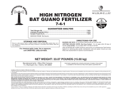


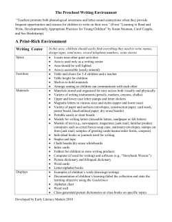
© Copyright 2026