
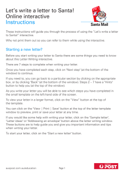
Window Treatment Wallstations for use with 3000 Series and 4000 Series systems
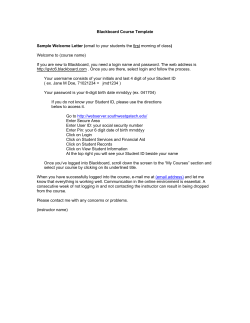
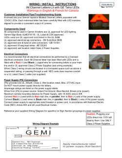
030747b
8/28/02
10:12 AM
Page 1
TM
LUTRON
Window Treatment
Wallstations
for use with 3000 Series and
4000 Series systems
✓ SG-2W
❑
✓ SG-3W
❑
✓ SG-3WRL
❑
✓ SG-3WD
❑
✓
❑ SG-5WRL
030747b
Note:
8/28/02
10:12 AM
Page 2
Window Treatment Wallstations can only control zones on GRAFIK Eye Control Units with software revision 7-0 or higher. Window
Treatment Wallstations will not function correctly with Control Units with lower software revisions.
SG-2W
Status
Indicator
LEDs
SG-3WRL
Status
Indicator
LEDs
Open Button
Close Button
SG-3W
Status
Indicator
LEDs
Open Button
Stop Button
Close Button
Raise/Lower Buttons
SG-3WD
Open Button
Stop Button
Close Button
Status
Indicator
LEDs
Button Functionality
Open Button
Stop Button
Close Button
Open Button
Stop Button
Close Button
Group 1
Group 2
SG-5WRL (Sivoia® only)
Pressing the Open, Close, or Preset button will cause the window
treatment to move to the selected oosition. Pressing the same Open,
Close, or Preset button a second time while the window treatments
are moving will sto the window treatments.
Open Button
Status
Indicator
LEDs
Open - Pressing the Open button once will cause the window
treatments to move to the open position.
Close - Pressing the Close button once will cause the window
treatments to move to the closed position.
Preset 1, 2, 3 Buttons
Close Button
Raise/Lower Buttons
Stop Pressing the Stop button will casue the movement of the
window treatments to stop.
Raise - Holding the Raise button will cause the window treatments to
move towards the open position. Releasing the Raise button will
cause the window treatments to stop.
For SG5WRL only:
Lower - Holding the Lower button will cause the window treatments
to move towards the closed position. Releasing the Lower button will
cause the window treatments to stop.
Presets - Pressing one of the preset buttons (Preset 1, Preset 2, or
Preset 3) will cause the window treatments to move to their
programmed preset level.
Installation Instructions
2
Occupant Copy
030747b
8/28/02
10:12 AM
Page 3
Wiring Notes
Wallstation circuits are classified as Class 2 circuits (U.S.A.) and
PELV circuits (IEC). Unless otherwise specified, the voltages do
not exceed 24 VAC or 15 VDC. As Class 2 circuits, they comply
with the requirements of NFPA® 70 National Electrical Code®
(NEC®). As PELV circuits, they comply with the requirements of
IEC 60364-4-41, VDE 0100 Part 410, BS7671:1992 and other
equivalent standards. When installing and wiring to these
Wallstations, follow all applicable national and/or local wiring
regulations. External circuits connected to input, output, RS232,
DMX512, and other communication terminals of Wallstations,
must be supplied from a Listed Class 2 source or comply with
the requirements for PELV circuits, as applicable in your country.
■
■
CAUTION!
■
■
■
■
Lutron recommends that Wallstations be installed by a
qualified electrician.
Do not connect high-voltage power to low-voltage terminals. Improper wiring can result in personal injury or
damage to the control or to other equipment.
GRAFIK Eye Wallstations must be connected to the GRAFIK
Eye Control Unit by using Class 2/PELV wiring methods per
the National Electrical Code. Check with your local electrical
inspector for the local code requirements and wiring
practices allowed in your area.
Use only a cloth with warm water and mild soap to clean
faceplates (no chemical cleaners).
Occupant Copy
■
3
System Maximums:
— 8 Unique GRAFIK Eye addresses per system.
— 16 Wallstations per system.
— 8 GRAFIK Eye Sivoia Controllers per system.
— GRAFIK Eye 3000 Series Control Units can power a
maximum of 3 Wallstations.
— 2000 ft. (600 m) wiring length.
— 0 °C—40 °C operating temperature.
Wallstation Wiring
— 3000 Series: Four #18 AWG (1.0 mm2) Class 2/PELV
wires (2 twisted, pair). Lutron offers a one-cable, nonplenum, low-voltage solution (P/N GRX-CBL-346S500), and a one-cable, plenum, low-voltage solution
(P/N GRX-PCBL346S-500). Other suggested cables are
Belden No. 9156, Alpha No. 1132, or equivalent, for
GRAFIK Eye 3000 Series Control Units.
— 4000 Series: Two #12 AWG (2.5 mm2) Class 2/PELV
wires and two shielded #18 AWG (1.0 mm2) Class
2/PELV wires (twisted, shielded pair). Lutron offers a
one-cable (non-plenum), low-voltage solution (P/N
GRX-CBL-46L).
— Power: wires 1 & 2, 12 VDC-24 VFW.
— Data: wires 3 & 4, twisted, shielded pair.
Terminal 2 (power) must not be connected between GRAFIK
Eye 3000 Series Control Units.
Installation Instructions
030747b
8/28/02
10:12 AM
Page 4
Installation
Warning: Always turn Off the circuit breaker/MCB or
remove the main fuse from the power line before
doing any work. Failure to do so can result in serious
personal injury.
5. Address Wallstations. Each Wallstation
in a system must be assigned a
unique address. Set DIP switches 1—4
of each Wallstation to one of the positions
illustrated below and record its location.
Proper wiring of Wallstations is dependent upon the GRAFIK
Eye Control System that is providing power. GRAFIK Eye 3000
Series and GRAFIK Eye 4000 Series Control Units have different
power limitations and wiring techniques. Please confirm the
type of Control Unit to which the Wallstation is being wired and
use the corresponding instructions that follow.
Set
Address
1
2
3
4
For this address
Set switches
like this:
Set Switches
Location:
like this:
1 2 3 4
1. Turn power Off.
2. Mount standard U.S. 1-gang wallbox, 2.75 in. (70 mm)
deep (available from Lutron P/N 241-519).
3. Strip insulation from wires so that 3/8 in. (10 mm) of bare
wire is exposed for #18 AWG (1.0 mm2) wire.
Location:
1 2 3 4
1
9
2
10
3
11
4
12
5
13
6
14
7
15
8
16
3/8 in. (10 mm)
4. Remove the faceplate, adapter (if applicable), and button
assembly from the Wallstation to access DIP switches.
6. Backlight Option. Your Wallstation is
factory set for the backlight to be On.
The backlight can be switched on or
off by setting DIP switch 10.
Set
Backlight
10
Installation Instructions
4
Occupant Copy
030747b
8/28/02
10:12 AM
Page 5
7. Wiring must be done in a daisy-chain and 1-to-1
configuration (please see Installer's Guide included with
Control Unit for more information). Each Wallstation
terminal will accept up to two #18 AWG (1.0 mm2) wires.
3000 Series System Wiring. Connect four #18
(1.0 mm2) twisted pair wires to the Wallstation’s terminal
block.
4000 Series System Wiring. Connect two #18 (1.0
mm2) shielded, twisted pair wires to terminals 3 and 4 of
the Wallstation’s terminal block. Shielding must be
connected as shown, but do not connect to Earth/Ground
or Wallstation. Two #12 AWG (2.5 mm2) power wires will
not fit in the terminal blocks, however, #12 AWG
(2.5 mm2) is necessary due to voltage drop on the wire.
Use the diagram shown at right to make the connections in
the wallbox.
8. Mount Wallstations as shown below. Attach faceplate by
pressing in at each corner, one corner at a time. Restore
power.
Daisy-Chain Configuration
4
3
2
1
4 twisted pair,
#18 AWG
(1.0 mm2
3000 Series System Wiring
Drain
4
3
2
1
2 #12 AWG
(2.5 mm2)
2 #12 AWG
(2.5 mm2)
1 #18 AWG
(1.0 mm2)
Typical Mounting Diagram
Occupant Copy
4000 Series System Wiring
5
Installation Instructions
030747b
8/28/02
10:12 AM
Page 6
System Communications
Communication between Wallstation and Control Unit must be established prior to normal operation. Follow these steps:
1. Put the Wallstation in setup mode (only one Wallstation can be in setup mode at a time).
Press and hold the buttons indicated (see examples below) for about 3 seconds, until the LED(s) start cycling.
Note: SG-3WD can control 2 separate groups of window treatment zones. Only ONE (1) set of button controls can be in setup mode
at a time.
LEDs cycle
LEDs cycle
Press and
hold here for
setup mode
Press and
hold here for
setup mode
SG - 2W
SG - 3W
LEDs cycle
LEDs cycle
Press and hold
here for setup
mode (Group 1)
Press and hold
here for setup
mode (Group 2)
SG - 3WD
Installation Instructions
LEDs cycle
Press and
hold here for
setup mode
SG - 3WRL
Press and
hold here for
setup mode
SG - 5WRL
6
Occupant Copy
030747b
8/28/02
10:12 AM
Page 7
2. Identify the Control Unit(s) to be controlled by the Wallstation (All Units must be addressed!)
■
To add an individual window treatment zone from a Control Unit: Press the
All LEDs will light up
ZONE button for the window treatment zone to be controlled by the Wallstation. The
entire column of LEDs of this zone will turn on to indicate that the zone has been added.
Press here to add an
Repeat for each window treatment zone to be added to this Wallstation.
individual window
treatment zone
Note:
To remove a window treatment zone from a Wallstation: Put the Wallstation in
setup mode, then Press the ZONE button on the Control Unit. Once the
window treatment zone’s entire column of zone LEDs has turned OFF, the zone is no longer controlled by the
Wallstation.
■
Control Unit
To add all window treatment zones on a Control Unit: Press and hold the top
Press here
Scene button on the Control Unit to be controlled by the Wallstation for about 3 seconds
to add
entire
until the scene LEDs flash in unison. Repeat for each Control Unit that you want to add
Control
to this Wallstation.
Unit
Note:
To remove a Control Unit from a Wallstation: Put the Wallstation in setup
LEDs flash in unison
mode, then press the OFF button (below scene buttons) of the Control Unit to be
Off Button
removed until the scene LEDs stop flashing.
LUTRON
3. Exit setup mode. Press and hold the buttons indicated in Step 1 for about 3 seconds until the scene LEDs stop cycling .
For Reference ONLY
CAUTION! This setting chart is FOR REFERENCE ONLY. DIP Switches 5-9 for Window Treatment
Wallstations are factory set and SHOULD NOT be changed. Correct operation of the wallstation is
not guaranteed if these dip switches are changed.
5 6 7 8 9
5 6 7 8 9
SG - 3W
SG - 3WD
SG - 3WRL
SG - 5WRL
SG - 2W
On
Off
FOR REFERENCE ONLY! DO NOT CHANGE DIP SWITCHES!
Occupant Copy
7
Installation Instructions
030747b
8/28/02
10:12 AM
Page 8
Sivoia Motorized Window Treatment Preset Programming (SG-5WRL only)
Preset 1, 2, and 3 are programmable Sivoia presets. Preset positions are stored in the Sivoia Motorized Window Treatments. All
GRAFIK Eye Control Units and Sivoia keypads/IR transmitters command the Sivoia Motorized Window Treatments to travel to the same
set of presets. GRAFIK Eye Sivoia Controllers are needed for operation of Sivoia Motorized Window Treatments from Window Treatment
Wallstations. Communication between Wallstation, Control Unit, and Sivoia Controller must be established prior to programming the
presets. Follow these steps:
1. Adjust the window treatments to the desired position. To adjust window treatments individually, use the Open/Close
buttons on the Sivoia Motor Drive Unit. To adjust all window treatments simultaneously, use the Raise/Lower buttons on the
Wallstation or Sivoia Controller.
2. Press and hold the desired preset button for a minimum of 4 seconds. ‘PR’ will flash on the Motor Drive Unit display
and the button LED will flash on the Wallstation indicating that the preset has been saved.
Note: This preset change will affect all Sivoia window treatment zones that are programmed to communicate with the SG-5WRL.
Internet: www.lutron.com
E-mail: [email protected]
WORLD HEADQUARTERS
Lutron Electronics Co. Inc.,
TOLL FREE: (800) 523-9466
(U.S.A., Canada, Caribbean)
Tel: (610) 282-3800;
International 1- 610-282-3800
Fax: (610) 282-3090;
International 1-610-282-3090
ASIAN HEADQUARTERS
Lutron Asuka Co, Ltd.,
TOLL FREE: (0120) 083417 (Japan)
Tel: (03) 5405-7333;
International 81-3-5405-7333
Fax: (03) 5405-7496;
International 81-3-5405-7496
EUROPEAN HEADQUARTERS
Lutron EA Ltd.,
FREEPHONE: 0800 282107 (U.K.)
Tel: (207) 702-0657;
International 44-171-702-0657
Fax: (207) 480-6899;
International 44-171-480-6899
HONG KONG SALES OFFICE
Lutron GL (Hong Kong)
Tel: 2104-7733;
International 852-2104-7733
Fax: 2104-7633;
International 852-2104-7633
SINGAPORE
Lutron GL (Singapore)
Tel: 65 220 4666
Fax: 65 220 4333
Lutron Electronics Co., Inc.
Made and printed in U.S.A.
P/N 030-747 Rev.B 6/02
LIMITED WARRANTY
Lutron will, at its option, repair or replace any unit that is defective in materials or
manufacture within one year after purchase. For warranty service, return unit to place of
purchase or mail to Lutron at 7200 Suter Rd., Coopersburg, PA 18036-1299, postage prepaid.
This warranty is in lieu of all other express warranties, and the implied
warranty of merchantability is limited to one year from purchase. This
warranty does not cover the cost of installation, removal, or reinstallation, or
damage resulting from misuse, abuse, or improper or incorrect repair, or
damage from improper wiring or installation. This warranty does not cover
incidental or consequential damages. Lutron’s liability on any claim for
damages arising out of or in connection with the manufacture, sale,
installation, delivery, or use of the unit shall never exceed the purchase price
of the unit.
This warranty gives you specific legal rights, and you may also have other rights which vary
from state to state. Some states do not allow limitations on how long an implied warranty
lasts, so the above limitation may not apply to you. Some states do not allow the exclusion
or limitation of incidental or consequential damages, so the above limitation or exclusion
may not apply to you.
These products may be covered under one or more of the following U.S. patents:
4,835,343; 4,924,349; DES 422,567; DES 436,930; D453,742; D456,783 and
corresponding foreign patents, other patents pending.
Lutron, GRAFIK Eye, and Sivoia are registered trademarks, and seeTouch is a trademark of
Lutron Electronics Co., Inc.
NFPA, National Electric Code, and NEC are registered trademarkds of the National Fire
Protection Association, Inc., Quincy, Massachusetts.
© 2002 Lutron Electronics Co., Inc.


© Copyright 2026