
TWL-1160FII /860FII Automatic Processor Instruction Manual
Toray Waterless Plate
Automatic Processor
TWL-1160FII
/860FII
Instruction Manual
2006.7 rev.2
86F2-001/11F2-002 ∼
Introduction
Introduction
Thank you for your purchasing Toray’s waterless plate automatic processor.
This document is the instruction manual describing functions and operation/work procedures and cautions for using/safety in order to use Toray’s waterless plate automatic
processor safely and fully utilizing its functions. Before using this machine, please read
this manual and understand the operation/work procedures thoroughly.
The items described in "For Safe Use" of this instruction manual and those
marked
in the procedure explanation sentences are cautions for safe use and
must be observed.
As to the MSDS of the treating solutions to be used together with the automatic processor, it should be obtained from the dealer and read prior to use.
Cautions in Using This Document
1 No part of this manual can be reproduced in any form without permission.
2 The contents of this manual are subject to change without notice when this product
is improved.
3 Do not operate/work using methods other than those described in this manual.
There is a possibility that unexpected failures or accidents are caused with
undescribed operate/work using methods.
We may not responsible for the accident with undescribed operate/work methods.
4 If there are any unknown points, errors, or omissions in this manual, please let us
know.
TWL-1160FII/860II Instruction Manual i
Contents
1
2
3
4
Prior to Use
1
For Safe Use
2
For Maintaining Performance of Machine
12
For Protecting Environment
14
Appearance/Names of Portions and Safety Devices
15
Names and Functions of Operating Portion
17
How to Operate Automatic Processor
21
Prior to Operation
22
How to Operate Automatic Processor
24
Daily Check Points and Maintenance Works
26
Maintenance
29
How to Check Level of Each Treatment Solution and Replenish
30
How to Control the Rate of Shower Flow
32
How to Clean Shower Pipe
34
Cleaning Overflow Filter of Developing Portion
36
How to Adjust Roller Nip Pressure
38
How to Grease
40
Cleaning Treatment Tank Interior
42
How to Measure Brush Pressure
44
How to Adjust Brush Pressure
46
How to Replace Filter of Pre-treatment Portion
48
How to Replace Filter of Developing Portion
50
How to Replace Filter of After-treatment Portion
52
How to Replace Filter of Water-washing Portion
54
How to Replace Molton(After-treatment portion)
56
How to Replace Molton(Water-Washing Portion)
58
Consumables and After-Sale Service
60
Alarm Occurrence
61
1. Level Alarm Lamp Lighting
62
2. Filter Alarm Lamp Lighting
64
ii TWL-1160FII/860II Instruction Manual
Contents
5
6
7
8
3. Solution Temperature Lamp Lighting
66
4. Plate Jamming Alarm Lamp Lighting
68
5. Buzzer Stop Lamp Lighting
70
How to Change Initial Set Conditions
How to Set Present Time
74
How to Set Automatic Start Time
76
How to Set Treatment Solution Temperature/Processing Speed
78
Troubleshooting of Processor
10
81
Unusual Machine Condition (Before Requesting Repair)
82
Main Breaker Cannot Be Turned ON
82
OK Lamp Does Not Light
84
Plate cannot be Inserted
84
Meandering of Plate
85
No Solution Coming from Shower
85
Brush Does Not Rotate
86
Occurrence of Abnormal Noise
86
Troubleshooting of Plate
89
Causes and Measurees for Positive Type Plate Faults
90
Causes and Measurees for Positive Type Plate Faults
91
Causes of Plate Faults Not Known
92
Instruction
93
Instruction Procedure
9
73
Control box layout drawing / Specification
94
107
Control Box layout drawing
108
Specification
109
Glossary / Index
111
Glossary
112
Index
114
TWL-1160FII/860II Instruction Manual iii
Composition of
Instruction Manual
How to Use
Instruction Manual
Be sure to use this instruction manual before operating the automatic processor.
Detailed work procedures and important information for preventing accidents
are described therein.
Procedure
The procedures for operating the automatic
processor and maintenance works are
described in accordance with actual works.
The works should be correctly done in
sequence. The marks in the procedure explanation indicate the following contents.
Tools necessary
8
+
4
The outline of this item is explained.
Caution for Safety
Procedure
Important points for safe work are described.
The safety instructions must be checked
before work is started.
1
2
3
Caution for Operation
Work check items and work-related cautions
are described.
P
Supplementary Item
Conditions of the automatic processor and
more detailed information during work are
described for your reference.
Check items and remedial methods when the
conditions are not improved through maintenance are described
iv TWL-1160FII/860II Instruction Manual
P
indicates reference page
1
Prior to Use
Important matters about this processor are described. Be sure to
read them before operating the automatic processor.
Especially as to the safety-related matters, safety education must
be given to those responsible for and in charge of the operation by
the controller of the automatic processor.
TWL-1160FII/860FII Instruction Manual 1
For Safe Use
For Safe Use
Be sure to read
Matters which m ust be observed for safe work are described
below. Before the automatic processor is used, the controller must
give safety education to those responsible for and in charge of the
operation.
Explanation of Caution/Warning Marks
Warning
Wrong handling may lead to serious injury or death.
Caution
Wrong handling may lead to injury or property damage.
WARNING
CAUTION
Notice
The instructions must be observed in order to work safetyand
maintain the machine performance.
TWL-1160FII/860FII Instruction Manual 2
For Safe Use
1. caution/ warning related operation
Prohibiting Removal
of Safety Device
WARNING
Function
Do not remove the functions of the emergency stop button
and side cover limit switch. There is a possibility of leading
to a serious accident.
Checking the
clothes
Do not wear the clothes which are easily caught by the processor,
when you operate the machine, for example, tie, accessory and so
on. Also, tie long hair to avoid being caught by the processor.
WARNING
Handling the
processor which is
heated abnormally
Machine
Modification
Prohibited
WARNING
Do not disassemble, repair or modify the machine. There is a
possibility of losing the safety functions and machine functions.
CAUTION
CAUTION
Use attachment s and parts which are recommended. If the
attachments and parts which are not recommended are used, there is
a possibility of losing safetyfunctions and machine functions.
CAUTION
When handling the plate, protective goggles and gloves must be
worn. There is a possibility of cutting hands with the plate edges or
damaging eyes.
Use of
recommended parts
Wearing Protectors
When Handling
Plate Material
There is a possibility of leading to fire and electric shock if the
processor is us edunder abno rmal conditions, for example selfheating, smoking, and smellingsomething burning.
TWL-1160FII/860FII Instruction Manual 3
Prior to Use
2. caution/warning related to chemicals
Wearing protective
goggles
CAUTION
Wear protective goggles to avoid damaging eyes by chemicals. If
the chemicals contact eyes, wash for 15 minutes and over, and seek
medical attention immediately
Prior to work, read the MSDS of the treatment s olution. If the
MSDS is missing, ask the dealer.
Reading MSDS
CAUTION
Use the hand pump to avoid spilling chemicals when chemicals are
poured.
Handling chemicals
CAUTION
Foam of aftertreatment solution
CAUTION
If the chemicals are spilled on the processor, wiring and floor, wipe
t hemimmediately. There is a possibility of leading to machine
trouble,
If the after-treatment solution foams up, add anti-foam agent
according to the instruction manual. If the solution overflows, wipe
t hem immediately. There is a pos sibilityof leading to machine
trouble, leakage and peeling the coating.
Wear protective graves and apron to avoid damaging s kin by
chemicals.
Wearing protective
graves and apron
CAUTION
After the chemicals are used, wash your hands.
Do not drink the chemicals. If someone drinks the chemicals are
drunk, follow the MSDS and seek immediately medical attention.
Prohibiting drinking
chemicals
CAUTION
Store the chemicals according to the MSDS. Keep in a place
inaccessible to children.
Storage of
chemicals
CAUTION
4 TWL-1160FII/860FII Instruction Manual
For Safe Use
3. caution/ warning related electricity
Be sure to connect the ground. If the connection is incomplete,
there is a possibility of electric shock.
Earth Connection
WARNING
Feed the voltage for the processor from the leakage breaker.
Use of leakage
breaker
CAUTION
If this leakage breaker is connected to a main leakage breaker
feeding voltage to other electric instillation, sensed current of the
leakage breaker must be larger than the main leakage breaker.
Use the processor within the bounds of regulation voltage.
Voltage deduction
CAUTION
There is a possibility of inviting errors due to voltage deduction
when the high-capacity equipments which have large load charge
are installed on the same power line.allowable voltage:230V±10%
Locate the cable to a pos iti on where t here is no contact to
chemicals and water. There is a possibility of leading leakage.
Protection from
water
CAUTION
Protection from step
CAUTION
Cover the cable by conduit if there is a possibility of pouring the
liquid tothe cable.
Do not tread and get stuck on the cable. If there is a possibility
oftreading the cable, cover the cable by cond uit to avoid the
possibility of leading to breaking the cable.
The cables deteriorate with age. Although the appearance is not
amaged, the cable may be damaged inside, so carry out routine
maintenance by professional.
Routine
maintenance
CAUTION
There is a possibility of leading to fire and sudden operation stop
by cable by deterioration.
Power Supply
Capacity
The main breaker of 3-phase 230V AC rating 30A or higher should
be used for the automatic processor alone.
maximum electric power consumption 7kW、frequency 50/60Hz
Power supply switch
Turn off the main breaker and primary side breaker, when the
processor is not used for a long time.
TWL-1160FII/860FII Instruction Manual 5
Prior to Use
4. caution/ warning related environment
Do not use the processor near the water. This is possibility of
leading to electric shock by the leakage
Prohibiting using the
machine near water
WARNING
Be careful not to trip
CAUTION
Do not place the unnecessary things around the processor. If there
is a possibility of leading to tripping by the cable and piping, warn
by labels.Oil pan is installed to the processor in case the chemicals
are spoiled. Ifthe oil pan is located on the floor, be careful not to trip.
There is a possibility of leading to oxidizing the processor due to
lack of air ventilation. Also, it may be harmful to operators.
Air ventilation
CAUTION
Prohibiting loading
materials
CAUTION
Confirm the MSDS and ventilate properly by the air fan.
Do not put materials, for example the bottle of water, on the
processor. There is a possibility of leading to injury by collapsing
and dropping.
Strength of floor
Confirm the strength of the floor whether t he floor has the
resistance to the weight of the processor. Body: 920kg Operation:
1020kg
Setting on flat
surface
Set the processor on the flat surface. There is a possibility of
leading to machine trouble, leakage and peeling the coating。
Resistance of floor
to water
There is a possibility to spill the water and chemicals, so the floor
should have resistance to water. Also, coating of floor must have
resistance to chemicals. Especially, be careful when there are
machines andequipments under the floor.
Sunshine/ Lighting
Use processse the processor where the sunlight and strong lighting
is covered.Also, use the yellow florescence lighting or the sleeve
which can cut ultraviolet. When the processor is used in the room
which has windows, cut the sunlightby lightproof curtain or yellow
acryl board.Handle the processor under the recommended condition
by the instruction
*Use the sleeve which ca n cut short-wavele ngth ultraviolet
(400mm and below)
6 TWL-1160FII/860FII Instruction Manual
For Safe Use
Operation space
Secure or. some space in order to maintain the processse
Vibration
Place the proces sor where there is no vibrati on. There is a
possibility of leading to negative impact to the quality and character
of processor.Earthquake resistance: 0.01G or lower
Dust
Do not use when there is a lot of dust. There is a possibility of
l eadi ng to the negative im pact to the quality and character of
processor. Clean up the space near the processor frequently.
Condition of
temperature and
humidity
Use the processor where the range of temperature and humidity is
low. Temperature: 10~30 degrees C Humidity: 30%RH~70%RH
Wind
Do not locate the processor where the wind blows directly. There
is a possibility to leading to the negative impact to the chemicals by
changing the density.
Installation of the
sink
If the temperature is quite low, there is possibility of leading to
dew condensation. There is a possibility of leading to the negative、
impact to the quality and character of processor.
Install the sink near the processor in order to wash.
Recommendation size: width 1.5m or over, length 0.3m or over
TWL-1160FII/860FII Instruction Manual 7
Prior to Use
5. caution/ warning related daily operation
Do not touch the rollers and brushes during operation. There is a
possibility of your hand being caught by them leading to injury.
No Touching of
Rollers and brushes
WARNING
Do not to operate the power switch by wet hand. There i s a
possibility of leading to electric shock.
Electric shock
WARNING
No Touching of
Control Panel
Wirings
Do not touch the control panel interior with bare hands. There is a
possibility of electric shock.
WARNING
Closing lid when
operating
WARNING
During operation, lid must be closed. There is a possibility of eye
damage due to splashing of the treatment solution or being caught in
the roller/brush leading to injury.
When the foreign object is mixed in the processor, turn off the
power switch and the power breaker imm ediately. There i s a
possibility of leading to out of control.
Removal of the
foreign object
CAUTION
Also, contact our company after the breaker is turned off.
Be careful not to catch a finger by lid when the lid is opened and
closing.
Catching a finger
CAUTION
Turn off the main
feed water valve
when the power
source is turned off.
Close the main feed water valve in order not to spill water in case
the piping is broken, when the power source is turned off.
CAUTION
Abnormal
circumstance
When alarm message is dis played, deal with the processor as
directed by manual. Contact the dealer when the problem continues.
Cock of waste
solution
Twist the cock to the correct direction. There is a possibility of
leading tospill the chemicals if the cock is turned to the wrong
direction.
8 TWL-1160FII/860FII Instruction Manual
For Safe Use
Tank for the
chemicals
Pour the chemicals (pre-treatment solution and after-treatment
solution) tothe correct tank. If the chemicals are poured to different
tank, there is a possibility of leading to have the negative impact to
the quality and character of processor.
Daily maintenance
Maintain the processor in according to t he maint enance list.
Contact t he dealer if the abno rmal circumstance is foun d, for
example spilling liquid and abnormal noise.
Prohibiting
unattendedoperation
Pr ohi bi t t he una tt ende d operat ion in cas e t he abnorm al
circumstance occurs.
Prohibiting removal
the side cover
If the side cover is removed, the drive system will be stopped by
the safety switch.Do not remove the side cover during operation.
TWL-1160FII/860FII Instruction Manual 9
Prior to Use
6. caution/ warning related repair and
maintenance
Power OFF prior to
Maintenance
Working
Referring to
Proceduresin
Instruction Manual
WARNING
CAUTION
Be sure to turn off the power breaker before removing the cover
and starting adjusting works. There is a fear of leading to a serious
accident. For working procedures,read and follow the instruction
manual.
The maintenance works must be correctly done in accordance with
t he procedures described in the instruction manual. The safety
cautions must be observed.
Wearing Protective
Goggles for
Adjusting Flow Rate CAUTION
of Shower
For checking the flow rate of shower, wear the protective goggles
to prevent splashing solution from entering your eyes because the
checking is done when the power is supplied. Especially when rid of
t he negative t ype pretreatment solution i s removed, protective
goggles must be worn to prevent mist from entering your eyes, and
contact lenses should be removed. There is a fear of eye trouble or
the contact lenses being deformed.
Fuse
Use the dedicated fuse. There is a possibility of leading to damage
if the dedicated fuse does not used.
CAUTION
Transport of heavy
parts
CAUTION
Wearing protect
groves during
maintenance
The protect groves must be worn during maintenance.
CAUTION
Keeping clean
CAUTION
Be careful to open
and close the lid
Be careful not t o drop the heavy part s when the parts are
t ransported.Wear safety shoes and transport the parts by two
persons. There is a possibility of damaging your body.
Clean up frequently when dusts pile on the cover. There is a
possibility ofleading to fire. Especially, when dusts pile on the pump
and motor of the cooling fan, there is a possibility of leading to
damage and fire by heating the processor.
Be careful to open and close the upper and side cover. There is a
possibilityof leading to catching a finger and breaking the cover or
the processor.
10 TWL-1160FII/860FII Instruction Manual
For Safe Use
Freeze
There is a possibility of leading to machine trouble and disordered
functi on i f the chemicals and liqui d is iced. Keep the room
temperature at zero degree or more at any time.
Boiled water
Do not pour the boiled water to the tank. There is a possibility of
leading to transforming the tank. When the tank is washed, use
warm water at 40 degrees or less.
TWL-1160FII/860FII Instruction Manual 11
Prior to Use
For Maintaining Performance of
Machine
Be sure to read
Items necessary for maintaining the machine performance are
described below. Periodical machine maintenance must be carried
out.
Important Items
Contents necess ary for maint aining the performance of the
machine are shown below.
Periodical Greasing
of Bearing
Greasing must be periodically done. If greasing is neglected,
bearing and shaft wear out may be caused.
Checking the
switching water
valve
If the water valve is not opened, during operation there is a
possibility of silicone sticking between the bristles of the developing
brush, and the brush will wear out.
Checking Treatment
Solution Level
If the treatment solution becomes too low, the machine will not be
operated. Be sure to the replenish solution more than minimum
level.
Checking Flow Rate
of Shower
If the shower flow rate is low, plate faults may be caused.
Checking Plate
Edge before
Inserting
If the plate is bent, transporting trouble will be caused. Before
inserting the plate into the processor, check if it isn't bent.
Periodical
Replacement of
Filter
If filter replacement is neglected, plate faults may be caused due to
insufficient shower flow.
Periodical
Replacement of
Brush
The brush attached to the machine is consumable, and i f it is
deteriorated, plate faults may be caused. It is necessary to replace it
either every 2 years or 20,000 plates to maintain the developing
performance.
12 TWL-1160FII/860FII Instruction Manual
For Maintaining Performance of Machine
Periodical
Replacement of
Roller
If transporting roller is deteriorated, slippage, bending or solution
cutting fault may occur, resulting in plate faults. It is necessary to
replace it either every 2 years or 20,000 plates to maintain the
performance.
After-Sale Service
The after-sale service will be done in accordance with the attached
sheet of aftersale service rules. Contact the dealer.
TWL-1160FII/860FII Instruction Manual 13
Prior to Use
For Protecting Environment
Be sure to read
The following describes the methods of disposing of waste/waste
solution produced in the waterless plate processing and automatic
processor operation. They shoul d be disposed of in a correct
method.
Methods of Disposing of
Waste Solution/Waste
The following shows how to dispos e of waste solution/waste
produced.
Unprocessed Plate
Case/Slip Sheet
Cover Film
Request for the disposal should be made to a wastepaper recovery
firm.
This should be disposed of as waste plastics.
(Material : positive type PET, negative type PP, CTP type PP)
Unprocessed Plate/
Processed Plate
Request for the disposal should be made to an aluminum recovery
firm. (Same as for the conventional PS plate)
Unnecessary
TreatmentSolution/
Waste Solution
Basically replenishment is made for loss and no waste solution is
produced, but if waste s olution is produ ced for some reason, it
s hould be dis pos ed of in accordance wit h t he M SDS of each
treatment solution.
Container for
foul solution
Use the bottle which had contained the chemical or a dedicated
plastic bottle for chemical, when disposing foul solution.
There is a possibility of leading to chemical leaking by container
corrosion if foul solution is put into the wrong bottle.
Draining Developing
Water
Filter
Please ask if to the polution control office in your area, because
each area has different Water Polution Law and Sewage Water Law.
It should be disposed of as waste plastics .
(material PET, PP + silicone rubber residue)
14 TWL-1160FII/860FII Instruction Manual
Appearance/Names of Portions and Safety Devices
Appearance/Names of Portions and
Safety Devices
Appearance/Names of
Portions and Safety
Devices
The automatic processorOs appearance, names of portions, and
functions and positions of safety devices are described below. They
s hou ld be remembered because they appear in the t ext of the
instruction manual.
Appearance and Names of Portions
Sketch Drawing
Lid
Left side cover
Emergency
stop button
Right side cover
Level gauge
Water
flowmeter
Water washing
portion
After-treatment
portion
Developing
portion
Operation portion
Power breaker
Pre-treatment
portion
Developing water flowmeter
Safety Devices
Emergency Stop Button
For securing safety, it is provided on the cover shown below.
ON (push in) : Electricity is cut off by the breaker, and the button is
locked.
OFF (release) : Turn the button in the arrow direction until it stops.
Position of emergency stop button
TWL-1160FII/860FII Instruction Manual 15
Prior to Use
Side Cover Limit Switch
It is provided within the right/left side cover. Unless the cover is at
its fixed position, the breaker cannot be turned on.
Position of side cover limit switch
Excess Rise Prevention Unit
For securing safety (to prevent abnormal rise of temperature), it is
provided on the pre-treatment lower frame.
Position of excess rise prevention unit
0
30
0 100
0 11
90
12
℃
70
80
60
50
40
Warning Labels Shown on
Equipment
On operation portion
CAUTION
Read instruction manual
before operating switch.
On each rid
CAUTION
Open gears
Will cause severe
personal injury.
On each rid
CAUTION
CAUTION
Open rollers.
Can cause severe
personal injury.
Chemical splash or
vapor.
Can burn eyes.
Control box
16 TWL-1160FII/860FII Instruction Manual
On each side cover
On each brush cover
DANGER
DANGER
Hazardous voltage.
Will cause severe
injury or damage
transformer.
Open rollers.
Can cause severe
personal injury.
Names and Functions of Operating Portion
Names and Functions of
Operating Portion
Names and Functions of
Operating Portion
The names and functions of the operating portions often used
during dail y operat ion a re shown bel ow. They should be
remembered because they appear i n the text of the ins truction
manual.
Operation Panel
COUNTER
GROSS COUNTER
COUNTS
COUNTS
1
2
TEMPERATURE
℃
℃
℃
3
3
3
Pre-treatment
Developing
Water washing
PRE
DEV
15
15
LEVEL
FILTER
14
14
AFTER WATER
15
14
TEMP.
4
JAM
5
BEEP
STOP
6
15
14
ALARM
S M T W T F S
− − −
13
7
1 0 0
+ +
+
SPEED(cm/min)
TIMER
12
11
CHECK ROLLER
10
9
PUMP
AUTO
8
POWER
TWL-1160FII
TORAY WATERLESS PLATE PROCESSOR
TWL-1160FII/860FII Instruction Manual 17
Prior to Use
Indication of number/
total number of plates
processed
1
Indication of treatment
temperature
GROSS COUNTER :
Counter to indicate the total number of plates passed
2
COUNTER :
Counter to indicate the number of plates passed.
It is equipped with a reset function and used for controlling the
number of plates, etc.
3
TEMPERATURE :
Temperature setting of pre-treatment solution/developing water/
washing water, alarm temperature setting, and indication of
present temperature
Indication of machine
abnormality alarm
4
TEMP. :
Switch/lamp to reset solution temperature alarm
When lit : treatment solution temperature is abnormally high
5
JAM. :
Switch/lamp to reset plate jamming alarm
When lit : occurrence of plate jamm ing in the developing
machine
6
BEEP STOP :
Switch/lamp to stop the buzzer
When lit : pump or motor is overloaded.
Developing speed
setting
7
SPEED :
Switch to set the treatment speed of the developing machine.
8
POWER :
Switch/lamp to turn ON/OFF the power
Power switch
When lit : power ON
When dark : power OFF
Auto/manual select switch
9
AUTO :
Switch/lamp to turn ON/OFF the automatic operation
When dark : automatic operation impossible
(automatic operation:OFF)
When flickering : during preparation for automatic operation
(automatic operation : ON)
When lit : automatic operation possible
(automatic operation : ON)
18 TWL-1160FII/860FII Instruction Manual
Names and Functions of Operating Portion
Manual mode switch
10
PUMP :
Switch/lamp to switch ON/OFF the operation of only the pump
when the automatic operation is OFF.
When lit : during pump operation
11
ROLLER :
Switch/lamp to switch ON/OFF the operation of only the
carrying motor when the automatic operation is OFF.
When lit : during operation of carrying motor
12
CHECK :
Switch/lamp to switch ON/OFF the brushing width measuring
operation (when brushing width of each brush is measured)
when the automatic operation is OFF.
When dark : plate passing impossible
(measuring operation : OFF)
When f lic kering : during prepar ation f or brushing width
measuring operation
(measuring operation : ON)
When lit : brushing width measuring operation possible
(measuring operation : ON)
Time/start timer setting
13
Indication of
maintenance alarm
14
Timer :
Timer capable of setting the time when the automatic operation
is turned ON
Filter :
Switch/lamp to reset the filter alarm
When lit : filter is clogged and must be replaced.
15
Solution level :
Switch/lamp to reset the solution level alarm
When lit : the quantity of treating solution is lower or higher
tha n the spe cif ied leve l, a nd re ple nishing or
draining is required.
TWL-1160FII/860FII Instruction Manual 19
Prior to Use
20 TWL-1160FII/860FII Instruction Manual
2
How to Operate
Automatic Processor
Before operating the automatic processor, be sure to check prior to
work and then turn on the power. During operation, always check
that the machine is operating normally.
TWL-1160FII/860FII Instruction Manual 21
How to Operate Automatic Processor
Prior to Operation
Checking prior to
Operation
Before operating the automatic processor, check/confirm on the
items described below to make sure that the operation preparation is
completed.
Checking prior to Operation
Checking breakers in
control panel
1
Check that four breakers inside the control panel under the carryin base is ON.
NFB1,NFB2,CP1,CP3
Control Panel under Carry-In Base
NFB2 CP1
NFB1
CP3
2
Check that one breaker inside the control panel under the water
washing portion is ON.
NFB3
Control panel under water-washing portion
NFB3
Checking Covers
3
Check if lid is installed at its fixed position.
22 TWL-1160FII/860FII Instruction Manual
Prior to Operation
4
Check if the side covers are installed at their fixed positions.
If the side covers are not installed, the limit switch works and
the power breaker cannot be switched on.
Checking Emergency
Stop Switch
5
Check that the emergency stop button is unlocked.
I f the e mergency stop button is locked, the power breaker
cannot be switched on.
Checking Treatment
Solution Level
6
Check if each treatment solution quantity is sufficient.
Solution Level Gauge of Treatment Tank
Green line
(upper limit)
Red line
(lower limit)
O.K.
Replenishing required
If insufficient, the alarm sounds and the alarm lamp lights.
Checking Fresh Water
Supply Line
7
Check if the fresh water supply valve of the water washing
automatic water supply and the main valve are opened.
Position of fresh water supply valve
I f the operation is started with the valves closed, the level
decrease occurs and the alarm sounds and the alarm lamp lights.
8
Check the floor around the processor for solution leakage from the
piping.
TWL-1160FII/860FII Instruction Manual 23
How to Operate Automatic Processor
How to Operate
Automatic Processor
Prior to Operation
Before operating the automatic processor, carefully read t his
operation explanation and correctly operate in accordance with the
following procedure. In order to maintain the machine performance,
the checking and maintenance works must be done.
Procedure
Preparation for Operation
1
Switch ON the power breaker of the control panel at the lower part
of the carry-in base .
Control panel at the lower part of carry-in base
Power Breaker
Power Breaker
OF
F
TRI
PP
ED
ON
2
Switch ON the [POWER] switch of the operating position.
[POWER] lamp lights.
CHECK ROLLER PUMP
AUTO
2
3
POWER
1
Switch ON the [AUTO] switch of the operating portion.
When timer setting is used, it is not necessary to switch ON the
[AUTO] switch.
Timer setting
P
74
he temperature control of pre-treatment solution, developing
solution, a nd water washing solution star ts. The [A UTO] lamp
flickers until the temperature reaches the set value.
4
If the temperature reaches the set value and the [AUTO]
lamp
changes from flickering to lighting and the plate inserting port OK
lamp lights, the plate processing can be started.
24 TWL-1160FII/860FII Instruction Manual
How to Operate Automatic Processor
[AUTO] switch lighting conditions
・Elapse of 5 seconds after the earth leakage breaker is turned ON.
・The solution temperature of pre-treatment/developing/water
washing has reached the set value.
・Pre-treatment/developing/water washing inlet/outlet sensors are
OFF (plate not detected).
・No occurr ence of abnorm alities such as shown in the alarm
function list.
OK lamp
Automatic Operation
5
Confirm the lighting of [AUTO] lamp and plate inserting port OK
lamp.
6
Remove the cover film of the plate already exposed and insert the
plate.
C orrec t the plate end if bent. The sensor installed to the
inserting board works, the transporting roller rotates, the plate is
pulled into the processor, and automatic developing is done.
Pre-treatment
inlet sensor
Stopping Operation
7
At the completion of the work, set to OFF the [AUTO] switch and
[POWER] switch in that order.
CHECK ROLLER PUMP
AUTO
1
POWER
2
When the timer setting is used, the [POWER] switch must be
left in the ON state. If OFF, the timer does not operate.
TWL-1160FII/860FII Instruction Manual 25
How to Operate Automatic Processor
Daily Check Points and Maintenance Works
Checking/maintenance
(daily checking) before
power is turned on
1-1 Is the pre-treatment/after-treatment solution level proper?
・Checking the level gauge in the pre-treatment/after
-treatment solution tank.
Replenish if insufficient.
P
30
1-2 Is the developing/water washing water level proper?
・Checking the developing/water washing water level
gauge.
Replenish if insufficient.
P
30
1-3 Is the overflow filter of the developing portion clogged?
・Visual checking of filter
Clean if residue is accumulated.
Checking/maintenance
(daily checking)
during operation
P
36
2-1 Are the shower pipe holes of each tank clogged?
・Visual checking of uniformity
Clean the pipe if clogged.
P
34
2-2 Is the flow from the shower pipe of each tank sufficient?
(Weekly checking)
・Visual checking of flow
Adjust the flow rate if insufficient.
32
・In sufficient even when the valve is fully opened.
Replace the filter.
48-55
P
P
2-3 Is liquid squeezing/transportation good?
・Visual checking of transportation.
Adjust the roller nip pressure if wrong.
P
38
・Faulty even after the adjustment
Replace rollers.
・Visual checking of liquid squeezing
Replace the molton if the plate is contaminated.
P
56-59
2-4 Isn't silicone residue accumulated in developing/after-treatment
tank?
・Visual checking of tank interior
Clean if accumulated.
Periodical checking/
maintenance
(monthlychecking)
P
42
3-1 Greasing portions of automatic processor
P
40
3-2 Measuring/adjusting brushing width P
44-47
26 TWL-1160FII/860FII Instruction Manual
How to Operate Automatic Processor
Checking Development of Plate Processed
Checking degree of
exposure/dot reproducibility
(monthly checking)
4-1 Is the degree of exposure proper?
・Checking the degree of exposure with the step guide
Adjust the exposure time if outside the standard range.
4-2 Are the dots reproduced as the film?
・Visual checking of plate dot reproduction
Measure the brush pressure if some dots are lost.
・Brush pressure is low
Adjust the brush pressure.
P
44
P
46
・Not remedied by adjusting
Replace the developing brush.
・
TWL-1160FII/860FII Instruction Manual 27
How to Operate Automatic Processor
28 TWL-1160FII/860FII Instruction Manual
3
Maintenance
he checking and maintenance works to maint ain the machine
performance must be carried out without fail. Please prepare/stock
consumables necessary for the maintenance works.
For actual working, be sure to follow the described procedures.
Pay special attention to the safety caution contents (the following
mark) and be sure to follow the instructions.
TWL-1160FII/860FII Instruction Manual 29
Maintenance
How to Check Level of Each
Treatment Solution and Replenish
Solution level checking
and replenishing
Since the treatment solution decreases as it is used, it should be
checked about once a week. When the solution level approaches the
lower limit, the solution should be replenished in accordance with
the following procedure.
Procedure
Checking Level of Each Treatment Solution
Checking Treatment
Solution Level
1
With each liquid level gauge on the right side, check that the
treatment solution level in between the red line (lower limit) and
green line (upper limit). If it is lower than the red line (lower limit),
replenish the solution in the following procedure.
Solution Level Gauge of Treatment Tank
Green line
(upper limit)
Red line
(lower limit)
O.K.
Replenishing required
Replenishing Each Treatment Solution
Checking Treatment
Solution Label
2
Check the treatment products label to see if the treatment solution
for repl enishing is correct. For the developing/water washing
portion, city water is used for both positive and negative types.
Name of treatment solution for automatic processor
For the developing portion, city water is used for both positive
andnegative types.
Pre-treatment solution
After-treatment solution
Position type PP-1
PA-F
Negative type NP-1
NA-1
CTP type DP-1
NA-1
30 TWL-1160FII/860FII Instruction Manual
How to Check Level of Each Treatment Solution and Replenish
Preparation for working
3
Set the [POWER] switch of the operating portion to OFF and then
set the power breaker of the processor to OFF.
Be sure to turn off power before starting the work
4
Remove the lid of the treatment portion short of the treatment
solution.
The lid should be rem oved by two per sons holding both
sides.There is a possibility of damaging the lid due to dropping,
etc
Replenishing Solution
5
In the case of the after-treatment portion, the brush cover should
also be removed.
6
While checking the level gauge, put in each treatment solution
until the solution level reaches the upper limit green line.
Wear protective goggles to prevent splashing solution f rom
entering your eyes, and wea r rubber gloves to pre vent it f rom
sticking to your skin.
When the treatment solution is replenished from a 18-liter can,
use the baby pump provided instead of putting it in directly from
the can. Be careful not to put it in the adjacent tank.
For the afte r-tr eatm ent portion, put in the solution over the
bursh.
If the solution is replenished too much, remove the right side
cover of the r elevant ta nk, place a proper c onta ine r or the
treatment solution can under the drain valve under the liquid level
gauge, and slowly open the drain valve to drain the solution.
Checking after Replenishing
Treatment Solution
7
Return the removed brush cover and the lid (right side cover) to
their original positions.
8
Check the level of the developing water/treatment solution with
the liquid level gauge again.
9
If the specified level is reached, the automatic operation can be
started.
The Level of Developing/Water Washing
Solution Decreases
Fresh water supply valve is
closed
・Check the water supply valve of water washing portion.
Quantity of water supplied is
insufficient
・Check the value of the flow setter and adjust if lower than the specified
quantity.
TWL-1160FII/860FII Instruction Manual 31
Maintenance
Dedicated
How to Control the rate of
Shower Flow
Controlling shower
flow rate
The rate of shower flow gradually decreases due to clogging of the
filter of the pretreatment/developing/after-treatment portion. Check
the rate of shower flow and adjust the opening of the shower flow
valve according to the following procedure, if it is low.
Procedure
Checking the Rate of Shower Flow
/Spraying Direction
Preparation for working
1
Remove lid of each treatment portion. For the developing, aftertreatment, and water washing portions, the brush cover should also
be removed.
When the lid is removed, wear protective goggles to prevent
splashing solution from entering your eyes. Especially in the
negative type pre-treatment portion, mist tends to occ ur, and
conta ct lenses must be removed and your face must not be put
near the top of the pre-treatment tank.
The lid should be removed by two persons holding both sides.
Ther e is a possibility of the c over being da ma ged due to
dropping,etc.
2
3
Turn ON the power breaker of the processor.
Set the [POWER] switch of the operating portion to ON and press
the [PUMP] switch in the manual operation mode ( [AUTO] switch
is dark).
CHECK ROLLER PUMP
AUTO
POWER
Pre-treatment, developing, after-treatment, and water
washing pumps all operate.
4
Check the shower solution quantity of each portion and the shower
direction. If the solution quantity is excessive or short, adjust the
rate of shower flow in the following procedure.
32 TWL-1160FII/860FII Instruction Manual
How to Control the rate of Shower Flow
Proper rate of shower flow means that the treatment
solution comes out uniformity through all the holes and
does not fly over the brush and carrying rollers.
Please refer to the following drawing for shower direction.
Shower direction
Pre-treatment portion
After-treatment portion
Developing portion
Water washing portion
Adjusting Shower Flow Rate
Adjusting Flow Rate
5
The rate of shower flow is to be adjusted with the flow rate
adjusting valve located at the base of the shower to be adjusted.
Shower flow rate adjusting tool
The valve operation should be down slowly taking care not to
scatter the solution. Wear protective goggles during working.
If the holes of the shower outlet are clogged, remove and clean.
6
After the adjusting is completed, return the brush cover and lid to
their original positions.
7
Press the [PUMP] switch of the operating portion to stop the
s hower and press the [AUTO] switch to return to the automatic
operation mode.
Solution Flow Is Low Even When Valve Is
Fully Opend
Shower pipe holes are
clogged with foreign matter
Filter is clogged
Check if the shower pipe holes are clogged. If so, clean.
Check the number of plates processed to see if the filter is to be
replace. In the case of 1000 plates or more, the filter may be clogged
and should be replaced.
TWL-1160FII/860FII Instruction Manual 33
Maintenance
How to Clean Shower Pipe
Cleaning shower pipe
Check if the shower solution comes out uniformly. If the pipe holes
are clogg ed, clean the shower pi pe according to the followin g
procedure.
Procedure
Checking for Shower Clogging
Preparation for working
1
Remove the lid of each treatment portion. For the developing/
after-treatment/water washing portion, the brush cover should also
be removed.
When the lid is removed, wear protective goggles to prevent
splashing solution from entering your eyes. Especially in the
negative type pre-treatment portion, mist tends to occ ur, and
conta ct lenses must be removed and your face must not be put
near the top of the pre-treatment tank.
The lid should be removed by two persons holding both side.
Ther e is a possibility of the cover being damaged due to the
dropping, etc.
2
3
Set to ON the breaker of the processor.
Set to ON the [POWER] switch of the operating portion and press
the [PUMP] switch in the manual operation mode ( [AUTO] switch
is dark).
CHECK ROLLER PUMP
AUTO
POWER
Brush Carry Pump Auto Power
Checking for clogging
4
Check the shower of each portion for clogging. If clogged, clean
the shower pipe holes in the following procedure.
Cleaning Shower Pipe
Preparation for working
1
Press the [PUMP] switch of the operating portion to stop the
shower and set to OFF the power breaker of the automatic processor.
34 TWL-1160FII/860FII Instruction Manual
How to Clean Shower Pipe
Be sure to turn off power before starting the work.
2
Remove the shower pipe.
Shower hole position fixing screw
2
3
Raise
Pull
1
Push
Valve side
To remove it, raise the right side while pressing the shower pipe
against the left side face.
Cleaning pipe holes
3
Remove the dust clogging the shower pipe holes, and clean the
holes with a brush, etc. while washing with water.
C lea n the holes with a wire or toothpick and wash out the
foreign matter in the shower pipe with water.
4
Depending on the extent of contamination, remove the cap at the
pipe end and clean the interior.
Shower pipe
Cap
5
Remove water and dry, and then return the cap to its original
position.
Since the hole position of the pipe diff ers between the end
portion and this portion, the cap must be correctly installed.
6
Return the shower pipe to its original position.
Set it in such a way that the screw of the end is fit in the notch.
7
Checking after cleaning
8
Return the lid to its original position.
Check if the solution from the shower comes out uniformly and if
t he direction of the solut ion coming out of the shower pipe is
correct.
TWL-1160FII/860FII Instruction Manual 35
Maintenance
Cleaning Overflow Filter of
Developing Portion
Cleaning overflow filter
The overflow f ilter of the developing portion prevents clogging of the
drain piping by recovering silicon residue which flows out together with the
drain. Check the recovered condition every day, and clean the filter in the
following procedure if residue has accumulated.
Procedure
Checking for Filter Clogging
Preparation for working
1
Set to OFF the [POWER] switch of the operation portion, and then
turn OFF the power breaker of the developing machine.
Be sure to turn off the power breaker before starting the work.
2
Remove the right side cover of the developing/after-treatment
portion.
Developing portion
After-treatment portion
Overflow filter
Checking for clogging
3
Open the lid of the filter box, remove the gauze filter together with
the PVC elbow, and then take it out.
36 TWL-1160FII/860FII Instruction Manual
Cleaning Overflow Filter of Developing Portion
Developing solution
overflow
Lid
Gauze filter
Removal
Filter box
Drain
Residue basket
4
Take out the residue basket.
5
Check the accumulated condition of the silicon residue inside,
remove the accumulated residue, and wash with water.
6
Check the gauze filter, remove accumulated residue, and wash
with water.
Gauze filter
7
8
Set the gauze filter and residue basket in the filter box and close the
lid.
Return the right side cover to its original position.
TWL-1160FII/860FII Instruction Manual 37
Maintenance
5
10
How to Adjust Roller
Nip Pressure
Adjusting roller pressure
The roller becomes smaller in outside diameter as it is used, ca using
trouble such as slipping of transportation, meandering, and solution cutting
f ault. If any such symptom appear s, adjust the pressure according to the
f ollowing procedure. No adjustment is re quired for some rollers with no
adjusting bolt.
Procedure
Checking Solution Cutting
Preparation for working
1
Remove lid of each treatment portion.
When lid is re moved, wea r protective goggles to prevent
splashing solution from entering your eyes. Especially in the
negative type pre- tr eatment portion, m ist tends to occur, so
conta ct lenses must be removed and your face must not be put
near the top of the pre-treatment tank.
Lid should be removed by two per sons holding both sides.
There is a possibility of the cover being damaged due to dropping,
etc.
2
Checking solution cutting
Set to ON the breaker of the processor.
3
Set to ON the [POWER]
operating portion.
4
Check that the [AUTO] switch and OK lamp are lit, and insert the
test plate.
5
6
switch and [AUTO] switch of the
Check the solution cutting of the carrying rollers.
If the solution cutting is bad, check the surface of the carrying
rollers (upper/lower) for foreign matter, and adjust the nip pressure
of the carrying rollers biased in the following procedure.
38 TWL-1160FII/860FII Instruction Manual
How to Adjust Roller Nip Pressure
Adjusting Roller Nip Pressure
Preparation for working
7
Set to OFF the [POWER] switch of the operating portion and then
turn OFF the breaker of the processor.
Be sure to turn off power before starting the work
Adjusting roller nip
pressure
Adjusting bolt
Lock nut
8
Hold the roller nip pressure adjusting bolt with a 5mm hexagon
wrench and loosen the lock nut with a 10mm spanner.
9
Screw in the roller nip pressure adjusting bolt 1/2 turn clockwise
and check the effect.
When both sides are adjusted, the screwing-in amount should
be same right and left. If the screwing-in amount is different at the
right and left, meandering will be caused.
Slide bush
10 If the improvement is not sufficient, screw it in another 1/2 turn.
It must not be screwed in 2 turns or more at a time. The roller
center will rise and solution cutting fault will be ca used. The
transporting motor will also be burdened resulting in failure. 11 After the adjusting is completed, fix (tighten) the lock nut.
Checking after adjusting
12 After the adjusting is completed, fix (tighten) the lock nut.
When the solution cutting and transporting is checked with the
lid removed, do not extend your hand to the roller.
13 After the work is completed, return the lid to its original position.
Not remedied even after adjusting
Roller fatigue
It is necessary to replace the roller every 2 years or 20,000 plates
(roller is consumable).
Consult the dealer (it is charged).
TWL-1160FII/860FII Instruction Manual 39
Maintenance
How to Grease
Grease
gun
Greasing
Gre as ing is indi spens abl e for ma int aini ng t he m achi ne
performance. If greasing is neglected, seizure of the bearing and
wear of the brush shaft will be caused. Greasing must be done at
least once a month according to the following procedure.
Procedure
Greasing-Up of Brush Bearing/Sprockets
Preparation for working
1
Set to OFF the [POWER] switch of the operating portion an then
turn OFF the power breaker of the processor.
Be sure to turn off power before starting the work.
2
Remove the side covers of each portion (no need to remove the left
side cover of pre-treatment).
If the breaker was not turned off, the limit switch would work
and the breaker would be turned off.
Greasing bearings
3
Grease up the brush bearings oscillating portion bearings on the
right side.
Brush bearing
Bearing
Brush bearing
Bearing
Oscillating portion bearing
Left side
4
Right side
Grease up the brush bearing portions on the left side.
40 TWL-1160FII/860FII Instruction Manual
How to Grease
Greasing sprocket
5
Supply grease to the carrying chain idler sprockets using a
grease gun.
The grease nipple is of standard type (conforming to JIS B-1575).
Grease
supply port
Idler sprocket
The grease nipple is of standard type.
(conforming to JIS B-1575)
A grease gun sold on the market can be used.
Example of lever type grease gun sold on the market: KH-120.
(Yamada Corporation)
As the grease, general-purpose type such as industrial or dinary
grease and lithium type grease can be used.
Gr e ase visc osity (c onsiste ncy) sha ll b e c la ss 2 of JIS
classification.
6
Return the right and left side covers to their original positions.
TWL-1160FII/860FII Instruction Manual 41
Maintenance
Cleaning Treatment Tank
3
Interior(Removal of Silicone Residue)
2.5
Tank cleaning
As the number of plates processed increases, s ilicone rubb er
residue scraped in the developing portion is accumulated in the tank.
Clean it at least once a week in the following procedure.
Cleaning Procedure
Preparation for working
1
Set to OFF the [POWER] switch of the operating portion and then
turn OFF the power breaker of the processor.
Be sure to turn off the power breaker before starting the work.
Cleaning Brush Cover of Developing/
After-Treatment Portion
Front
2
Rear
Remove the lid of the developing/after-treatment portion and
remove and water-wash the brush cover of each portion.
Lid should be removed by two persons holding both sides to
prevent it from being damaged.
3
Remove water and dry, and then return the brush cover and the lid
to their original positions.
Pay attention to the direction of the brush cover when installing
it.
Cleaning Developing/After-Treatment
Carrying Rollers
1
Remove the shaft fixing screws of the rider roller/carrying roller
and remove the shaft fixing metal parts.
Since a spring is contained in the slide bush, the fixing bolts
should be slowly loosened alternately on both sides to prevent
popout.
2
Remove the rider roller and then raise and remove the carrying
roller (upper) together with the slide bush.
42 TWL-1160FII/860FII Instruction Manual
Cleaning Treatment Tank Interior(Removal of Silicone Residue)
The carrying roller should be removed by two persons because
it is heavy.
When the carrying roller and rider roller are rem oved, care
must be taken not to drop the rubber bearing, spacer, slide bush
(both sides).
Shaft fixing screw
Adjusting bolt
Lock nut
Shaft fixing
metal part
Rider roller
Slide bush
3
Wipe off silicone residue and contaminant on the surface of the
carrying roller (upper).
4
Also wipe off contaminant on the whole surface of the carrying
roller (lower).
5
After cleaning, grease up the rubber bearings and assemble them
as before.
6
After adjusting the roll nip pressure, return the removed cover and
lid to its original portion.
7
Check meandering and liquid cutting through automatic operation
and adjust.
Cleaning Developing Brush
1
Developing
brush
Remove the brush cover.
2
Connect the provided hose to the fresh water supply valve and
open the valve.
3
Manually turn the brush while pouring water on the brush and
remove silicone residue on the brush surface with a wire brush.
Fresh water
supply valve
Be c areful to prevent water from enter ing the pre-treatment
tank and after-treatment tank.
After-treatment
brush
4
Return the removed cover and lid to its original position.
TWL-1160FII/860FII Instruction Manual 43
Maintenance
How to Measure Brush Pressure
Measuring Brush
Pressure
The brush pressure is already adjusted a t the tim e of delivery, but it
becomes necessary to periodically check/adjust it beca use the brushing
pressure will be reduced due to fatigue of the brush as it is used. Measure
the brush pressure according to the following procedure.
Procedure
Measuring Brush Pressure
Preparation for working
1
Set to ON the [POWER] switch of the operating portion.
2
Set to OFF the [AUTO] switch and ON the [CHECK] switch.
CHECK ROLLER PUMP
AUTO
POWER
he test plate should be inserted with the developed surface back
(aluminum surf ace up) for e asy observation of the brushing
width.
3
Brushing width
operation mode
4
After the [CHECK] switch lights, insert the test plate.
When the test plate is inserted, the brushing width operation mode
is set.
Operation Explanation
4-1 The ca rrying motor runs to fee d the plate to the specified
position (under the developing/after- treatment brush) a nd then
stops.
4-2 Simultaneously when the developing/after-treatment pumps
operate, the afte r-treatment brush rotates. After the elapse of 3
minutes, the developing and after-treatment brushes stop.
4-3 The ca rrying motor runs to fee d the plate to the specified
position (under water-washing brush) and then stops.
4-4 Simultaneously when the water-washing pump operates, the
water-washing brush rotates. After the elapse of 3 minutes, the
water-washing brush stops.
4-5 The carrying motor runs and the plate is carried out.
44 TWL-1160FII/860FII Instruction Manual
How to Measure Brush Pressure
(Reference)
・ When it is desired to apply only the developing/after-treatment
brushing width to the plate.
4-6 I f the [B uzzer Stop] la mp of the opera tion portion is
pressed for 5 seconds at the above process 4-4, movement is made
to the following process 4-5, thus making it possible to shorten
the time.
・ When it is desired to apply only the water-washing brushing width
to the plate.
4-7 I f the [B uzzer Stop] la mp of the opera tion portion is
pressed for 5 seconds at the above process 4-2, movement is made
to the following process 4-3, thus making it possible to shorten
the time.
Measuring brush
pressure
5
Brushing trace remains on the plate brought out. Measure the
width of the brushing trace.
Proper width
Developing brush 13 to 15mm
After-treatment brush 9 to 11mm
Water-washing brush 9 to 11mm
6
After the measurement of the brushing width is completed, set to
OFF the "BRUSH" switch of the operating portion.
7
If the brushing width (brush pressure) is found to be weak by
measuring the brush pressure, adjustment is required.
Plate passing direction
Brushing trace
13 ∼ 15mm
Developing brush
After-treatment brush
Water-washing brush
The brushing width a ppearing on the plate is different from
ac tua l br ush ar r ang em e nt. I t should be n oted tha t it is
programme d so that the brushing width of the water-washing
brush is between the brushing width of the developing brush and
that of the aftertreatment brush.
TWL-1160FII/860FII Instruction Manual 45
Maintenance
How to Adjust Brush Pressure
6
13
Adjusting brush
pressure
If reducti on in brus hing pressure i s found by t he periodical
checking of the brush pressure, adj us tment i s required. The
adj usting method is same for developing/after-treatment/water
washing. Adjust the brush pressure in the following procedure.
Procedure
Adjusting Brush Pressure
Preparation for working
1
Set to OFF the [POWER] switch of the operating portion and then
turn OFF the power breaker of the processor.
Be sure to turn off the power breaker before starting the work.
Adjusting brush
pressure
2
Remove the lid and brush cover of the treatment portion short of
brush pressure.
3
Loosen the brush receiving roller bearing fixing bolts (hereinafter
called bearing fixing bolts) with a hexagon wrench (6mm).
4
Fix the brushing width adjusting bolts (hereinafter called adjusting
bolts) with a spanner (13mm), and loosen the lock nuts (2 places on
one side) with the spanner (13mm).
5
Adjust the brushing width by turning the adjusting bolts.
Counterclockwise turning, as seen from the top, increases the
brushing width.
If the adjusting bolt is turned 60 degrees (f or one thread of
bolt), the brushing width is changed about 2mm.
The adjusting bolt should not be turned more than 1 turn,
except when the brushing width is extremely small.
If excessive or insufficient entirely, do not forget to adjust
sa me amount with the right and left brushing width adjusting
bolts.
6
After the adjusting is completed, fix the adjusting bolts with the
spanner and tighten the lock nuts.
Be careful not to forget to tighten them.
46 TWL-1160FII/860FII Instruction Manual
How to Adjust Brush Pressure
7
Replace the bearing fixing bolts, and fix them.
Brush bearing
Bearing fixing bolt
Checking after adjusting
brush pressure
Bearing fixing bolt
Brushing width
adjusting bolt
Brushing width
adjusting bolt
Lock nut
Lock nut
8
Replace the side cover removed
9
Turn ON the breaker of the developing machine.
10 Set to ON the [POWER] switch and [CHECK] switch of the operating
portion.
CHECK ROLLER PUMP
AUTO
POWER
11 Measure the brushing width again, and repeat the adjustment until
a proper value is obtained.
12 After confirming the increase in brush pressure, check the
development of the plate.
Development Is Not Recovered after Brush
Pressure Adjustment
Brush fatigue
It is necessary to replace the brush every 2 years or 20,000 plates
used (the brush is consumable). Consult the dealer (charged).
TWL-1160FII/860FII Instruction Manual 47
Maintenance
Dedicated
How to Replace Filter of
Pre-Treatment Portion
Replacing pre-treatment
filter
The pre-treatment filter recovers foreign matter dropped in the pretreatment tank such as remaining cover film pieces. Replace it at
least once a year in the following procedure.
Procedure
Replacing Pre-Treatment Filter
Preparation for working
1
Check if a spare filter is available.
The f ilter is c onsumable. It should be purchased in advance
from the dealer of the processor.
2
Set to OFF the [POWER] switch of the operating portion and then
turn OFF the power breaker of the processor.
Be sure to turn off the power breaker starting work.
3
Remove the right side cover of the pre-treatment portion.
If the breaker was not turned OFF, the limit switch would work
and the breaker would be turned off.
4
Close the pre-treatment filter inlet valve.
Pre-treatment portion
Level gauge
Open
Drain valve
5
Close
Inlet valve
Pre-treatment filter housing
Open the pre-treatment filter/drain valve, and drain the treatment
solution in the filter housing into a proper empty container.
About 500cc remains in the housing.
6
When the solution no more comes out of the drain valve,close the
valve.
48 TWL-1160FII/860FII Instruction Manual
How to Replace Filter of Pre-Treatment Portion
Replacing filter
7
8
9
Filter
Fit in the filter wrench from under the housing and turn it to the left
(clockwise as seen from the top) and remove it.
Remove the filter in the filter housing, and install a new filter.
Check that the O ring (packing) in the upper part of the filter
housing is fit in the correct position.
O ring
10 Set the filter housing to its original position by turning it to the
right (counterclockwise as seen from the top).
Filter housing
11 Check that the drain valve is closed and open the pre-treatment
inlet valve.
Drain valve
12 Readjust the opening of the pre-treatment shower flow control
valve to about half opened.
Open
Close
Just after the filter is replaced, the shower flow increases and
there is a possibility of the shower solution being scattered if the
valve remains fully opened, so it should be half opened.
13 Return the right side cover to its original position, set to ON the
breaker of the automatic processor and then turn ON the [POWER]
switch.
14 Press the "Pre-treatment Filter" switch for 5 seconds to reset.
The buzzer will sound and the counter for pre-treatment filter
will be reset.
Checking after replacing
15 Check with the liquid level gauge if the specified quality of
treatment solution is available.
If insufficient, replenish the pre-treatment solution. Care must
be taken when replenishing because if the water is mixed in the
pre-treatment portion, the developing performance is extremely
lowered.
16 Operate the automatic processor.
After the filter is replaced, the solution temperature decreases,
and no place can be passed for a while until the set temperature is
reached. Check that the [AUTO] switch is lit before inserting the
plate.
17 Check if the solution quantity from the shower pipe is proper.
TWL-1160FII/860FII Instruction Manual 49
Maintenance
Dedicated
How to Replace Filter of
Developing Portion
Replacing
development filter
The development filter recovers s ilicone residue of the line
drawing portion which is brushed off. Replace the filter in the
following procedure after the specified number of plates are
processed.
Procedure
Replacing Development Filter
Preparation for working
1
Check if a spare filter is available.
The filter is consumable. It should be purchased in advance
from the dealer of the processor.
2
Set to OFF the [POWER] switch of the operating portion and then
turn OFF the power breaker of the processor.
Be sure to turn off the power breaker starting work.
3
Remove the right side cover of the developing portion.
If the breaker was not turned OFF, the limit switch would work
and the breaker would be turned off.
4
Open the developing water drain valve and drain the developing
water in the tank.
Developing portion
Level gauge
Drain valve
(back of filter)
Open
Drain valve
5
Close
Developing filter
When the water no more comes out of the drain valve, close the
valve.
50 TWL-1160FII/860FII Instruction Manual
How to Replace Filter of Developing Portion
6
Open the development filter/drain valve, and drain the developing
water in the filter housing into a proper empty container.
About 500cc remains in the housing.
Replacing filter
7
When the water no more comes out of the drain valve, close the
valve.
8
Fit in the filter wrench from under the housing and turn it to the left
(clockwise as seen from the top) and remove it.
9
Filter
O ring
Filter housing
Drain valve
Open
Remove the filter in the filter housing, and install a new filter.
10 Check that the O ring (packing) in the upper part of the filter
housing is fit in the correct position.
11 Set the filter housing to its original position by turning it to the
right (counterclockwise as seen from the top) and check that the
drain valve is closed.
12 nsert the provided hose in the fresh water supply valve located to
the right side of the development brush, open the valve, and supply
the specified quantity of fresh water while observing the liquid level
gauge.
Close
13 Readjust the opening of the developing shower flow control valve
to about half opened.
Just after the filter is replaced, the shower flow increases and
there is a possibility of the shower solution being scattered if the
valve remains fully opened, so it should be half opened.
14 Return the right side cover to its original position, set to ON the
breaker of t he automati c process or and then set t o ON t he
[POWER] switch.
15 Press the [DEV/FILTER] switch for 5 seconds to reset.
The beep will sound and the counter for developing filter will
be reset.
Checking after replacing
16 Operate the automatic processor.
After the filter is replaced, the solution temperature decreases,
and no place can be passed for a while until the set temperature is
reached. Check that the [AUTO] switch is lit before inserting the
plate.
17 Check if the solution quantity from the shower pipe is proper.
TWL-1160FII/860FII Instruction Manual 51
Maintenance
Dedicated
How to Replace Filter of
After-Treatment Portion
Replacing
after-treatment filter
The after-treatment filter recovers foreign matter dropped in the
after-treatment tank such as silicone residue not removed in the
developm ent. Replace i t in the following procedure after the
specified number of plates are processed.
Procedure
Replacing After-treatment Filter
Preparation for working
1
Check if a spare filter is available.
The filter is consumable. It should be purchased in advance
from the dealer of the processor.
2
Set to OFF the [POWER] switch of the operating portion and then
turn OFF the power breaker of the processor.
Be sure to turn off the power breaker starting work.
3
Remove the right side cover of the after-treatment portion.
If the breaker was not turned OFF, the limit switch would work
and the breaker would be turned off.
4
Close the after-treatment filter inlet valve at the back of the liquid
level gauge.
After-treatment portion
Open
Close
Inlet valve
(back of level gauge)
Level gauge
After-treatment filter housing
Drain valve
5
Slowly open the after-treatment filter drain valve and drain the
t reat ment s olution in t he filter hous ing i nto a proper empty
52 TWL-1160FII/860FII Instruction Manual
How to Replace Filter of After-Treatment Portion
container.
About 500cc remains in the housing.
Replacing filter
6
When the solution no more comes out of the drain valve, close the
valve.
7
Fit in the filter wrench from under the housing and turn it to the left
(clockwise as seen from the top) and remove it.
8
Filter
9
O ring
Remove the filter in the filter housing, and install a new filter.
Check that the O ring (packing) in the upper part of the filter
housing is fit in the correct position.
10 Set the filter housing to its original position by turning it to the
right (counterclockwise as seen from the top).
Filter housing
11 Check that the drain valve is closed, and open the after-treatment
inlet valve.
Drain valve
Open
Close
12 Readjust the opening of the after-treatment solution shower flow
control valve to about half opened.
Just after the filter is replaced, the shower flow increases and
there is a possibility of the shower solution being scattered if the
valve remains fully opened, so it should be half opened.
13 Return the right side cover to its original position, set to ON the
breaker of the automati c process or, and then set to ON t he
[POWER] switch.
14 Press the [AFTER/ FILTER] switch for 5 seconds for resetting.
The beep will sound and the counter for after-treatment filter
will be reset.
Checking after replacing
15 Operate the automatic processor.
After the filter is replaced, the solution temperature decreases,
and no place can be passed for a while until the set temperature is
reached. Check that the [AUTO] switch is lit before inserting the
plate.
16 Check if the solution quantity from the shower pipe is proper.
TWL-1160FII/860FII Instruction Manual 53
Maintenance
Dedicated
How to Replace Filter of
Water-Washing Portion
Replacing
water-washing filter
The water-washing filter recovers silicon residue sticking to the
non-drawing portion. Replace it in the following procedure after the
specified number of plates are processed.
Procedure
Replacing Water-Washing Filter
Preparation for working
1
Check if a spare filter is available.
The filter is consumable. Purchase it in advance from the
dealer of the processor.
2
Set to OFF the [POWER] switch of the operating portion and then
set to OFF the power breaker of the processor.
Be sure to switch off the power breaker before starting the
work.
3
Remove the right side cover of the water-washing portion.
If the power breaker is not switched OFF, the limit switch will
operate and the breaker will be switched off.
4
Open the washing water drain valve at the lower right of the filter
and drain the washing water in the tank.
Water-washing portion
Water-washing filter
Ooen
Close
Level gauge
Filter drain valve
Drain valve
5
When the solution no more comes out from the drain valve, close
the drain valve.
54 TWL-1160FII/860FII Instruction Manual
How to Replace Filter of Water-Washing Portion
6
Slowly open the water-washing filter/drain valve, and drain the
t reat ment s olution in t he filter hous ing i nto a proper empty
container.
About 500cc remains in the housing.
Replacing filter
7
When the solution no more comes out from the drain valve, close
the drain valve.
8
Fit in the filter housing turning tool from under the housing, and
turn it to the left (clock direction as seen from the top) to remove.
9
Take out the filter in the filter housing, and install a new filter.
10 Check that the O ring (packing) at the upper part of the filter
housing is fit in the correct position.
11 Turn the filter housing to the right (counterclockwise direction as
seen from the top) to set it to its original position, and check that the
drain valve is closed.
Filter
O ring
12 Insert the hose provided on the fresh water supply valve located on
the right of the development brush, open the valve, and supply
specified quantity of fresh water into the water-washing tank while
watching the level gauge.
Filter housing
Drain valve
Open
Close
13 Readjust the opening of the water-washing shower flow adjusting
valve to about half-opened.
Immediately after the filter is replaced, the shower flow rate is
high, and there is a fear of the shower solution splashing if the
valve is fully opened, and so the valve should be half-opened.
14 Put back the right side cover to its original position, set to ON the
breaker of the automatic developing machine, and then ON the
[POWER] switch.
15 Press the [WATER /FILTER] switch for 5 seconds to reset.
The beep will sound and the counter for water-wash filter will
be reset.
Checking after replacing
16 Operate the automatic developing machine.
S ince the solution temperature dec reases after the filter is
replaced, the plate cannot be passed until the set temperature is
reached..Check that the [AUTO] switch is lit before inserting the
plate.
17 Check if the solution quantity from the shower pipe is proper.
TWL-1160FII/860FII Instruction Manual 55
Maintenance
3,4
How to Replace Molton
(After-treatment portion)
Replacing Molton
If the plate is heavily contaminated, check the contamination of the
molton.If heavily contaminated, replace the molton according to the
following procedure.
Procedure
Replacing Molton
Preparation for working
1
Set to OFF the [POWER] switch of the operating portion and then
turn OFF the power breaker of the processor.
Be sure to switch off the power breaker before starting the
work.
2
Slightly loosen both right and left lock nuts of the roller nip
pressure adjusting bolt, and then remove both right and left screws
of the shaft fixing metal part.
Shaft fixing screw
Shaft fixing screw
Shaft fixing
metal part
Shaft holding block
Nip pressure
adjusting bolt
Protective cover
Lock nut
Molton roller
Left side
After-treatment
outlet roller
Molton roller
(lower)
(upper)
3
4
Connecting
chain
Remove the protective cover of the molton roller.
Remove the shaft fixing metal part and shaft holding block and
raise/remove the molton roller (left figure).
Two persons should together taking care not to drop the rubber
bearing.
5
To replace the lower roller molton as well, remove the roller cover
on the left side, remove the connecting chain and sprocket in that
order, and raise and remove it like the upper roller.
Molton roller (lower) sprocket
56 TWL-1160FII/860FII Instruction Manual
How to Replace Molton (After-treatment portion)
Replacing molton
Binding string
6
Cut off the molton binding strings at both ends of the roller and
remove the molton from the roller.
7
Bind the string on one side of a new molton to the extent of the
roller shaft diameter.
8
Put in the bound portion on the one side of the roller shaft and
cover to the other end of the molton roller in the method of turning
inside out the socks.
9
Smooth the surface of the covered roller and bind the molton
binding string at the shaft portion.
Rubber bearing
10 Return the molton lower roller to its original position and return
the sprocket and chain to their original positions in that order.
11 Return the molton upper roller to its original position, return the
s haft holding block and shaft fixing metal part to their original
positions in that order, and fix the shaft fixing metal part with the
screws.
Do not forget to install the rubber bearing and shaft holding
block.
12 Tighten the roller nip pressure adjusting bolt and fix it with the
lock nut (both right and left).
13 Install the top/roller protective cover.
14 perate the automatic processor, pass a test plate, and adjust/check
the roller pressure to prevent the plate from meandering.
Contaminated Soon even after Replacing
Faulty cutting of aftertreatment solution
Check the squeezing of the after-treatment roller. If the liquid
cutting is faulty, adjust the roller nip pressure.
Abnormal shower
direction
f the shower direction is wrong, the solution may leak beyond the
after-treatment squeezing roller. Check the shower direction.
Change in composition of
after-treatment
solution
f water is mixed in the after-treatm ent s olution or moistu re
evaporates and the solution is concentrated, the plate face may be
contaminated. In such a case, the contamination preventive liquid is
to be put in. If the after-treatment solution foams too much, the
defoaming agent S is also put in.
TWL-1160FII/860FII Instruction Manual 57
Maintenance
3
+
How to Replace Molton
(Water-Washing Portion)
Replacing molton
If the plate is heavily contaminated, check the contaminated
condition of the molton. If heavily contaminated, replace the
molton according to the following procedure.
Procedure
Replacing Molton
Preparation for working
1
Set to OFF the [POWER] switch of the operating portion, and then
turn OFF the power breaker of the processor.
Be sure to turn off the power breaker before starting the work.
2
Remove the fan mounting cover at the upper part of the outlet.
On the emergency stop button side, cables are connected, and
so remove four mounting screws, turn it 90 degree centering on
the emergency stop button side, and place it on the side cover.
Cable connection side
Rear
Adjusting bolt
Lock nut
Emergency stop button
Front
Shaft fixing
metal part
Slide bush
3
Remove the shaft fixing part mounting screws, and raise and
remove the roller together with the slide bush (left illustration).
Since there are springs in the slide bush, care must be taken to
prevent them fr om popping out by alte rnately loosening both
fixing bolts slowly.
Two persons should work together so as not to drop the rubber
bearing.
58 TWL-1160FII/860FII Instruction Manual
How to Replace Molton (Water-Washing Portion)
Replacing molton
4
Cut off the molton binding strings at both ends of the roller, and
remove the molton from the roller.
Binding string
Rbber bearing
5
Bind the string on one side of a new molton to the extent of the
roller shaft diameter.
6
Put in the bound portion on the one side of the roller shaft and
cover to the other end of the molton roller in the method of turning
inside out the socks.
7
Smooth the surface of the covered roller and bind the molton
binding string at the shaft portion.
8
Return the molton roller to its original position, return the shaft
holding block and shaft fixing metal part to their original positions
in that order, and fix the shaft fixing metal part with the screws.
Do not forget to install the rubber bearing and spacer.
9
Tighten the right and left roller nip adjusting bolts, and fix them
with the lock nuts.
The work should be done in a ccordance with the roller nip
pressure adjusting procedure.
10
Replace the fan mounting cover at the upper part of the outlet.
For replacing the lower roller molton, contact the dealer.
TWL-1160FII/860FII Instruction Manual 59
Maintenance
Consumables and
After-Sale Service
Consumables and
Service Charged
The following consumables recommended to be normally stocked
should be stocked so that they can be readily used when necessary.
The following maintenance works are done charged by t he
manufacturer. Contact the dealer.
List of Consumables
Consumables
Pre-treatment solution
(for exchanging)
After-treatment solution
(for exchanging)
Filter (for replacing)
Transporting roller
(rubber changing)
Development brush
(brush changing)
After-treatment brush
(brush changing)
Molton
Standard
Stock
3.8 lit / 5 lit / 18 lit
Stock recommended
3.8 lit / 5 lit / 18 lit
Stock recommended
100μm
Product specified by
maker
Product specified by
maker
Product specified by
maker
4C with string (1160F)
4E with string (860F)
Stock recommended
Sequencer battery
Request when required
Request when required
Request when required
Stock recommended
Request when required
After-Sale Service
Works charged
1
Roller replacing (rubber changing)
The warranty period is 2 years or 20,000 plates passing whichever
is shorter.
2
Brush replacing (brush changing)
The warranty period is 2 years or 20,000 plates passing whichever
is shorter.
3
Replacing sequencer battery
The warranty period is 2 years.
4
Repairing failure parts
The warranty period for parts is 1 year. If the failure is attributable
to faulty maintenance, the repairing cost is charged even within the
warranty period.
60 TWL-1160FII/860FII Instruction Manual
4
Alarm Occurrence
If any alarm occurs during the operat ion of the autom atic
processor, immediately check the lamp indication of the control
panel and take the action of the corresponding item.
LEVEL
FILTER
PRE
DEV
1
2
5
6
AFTER WATER
3
7
TEMP.
9
4
8
JAM
10
BEEP
STOP
11
ALARM
TWL-1160FII/860FII Instruction Manual 61
Alarm Occurrence
If Alarm Occurs
1. Level Alarm Lamp Lighting
Level alarm
In order to facilitate maintenance, the alarm function of treatment
s olution level is provided and informs the timing. If the alarm
occurs, take the following measures.
Alarm Contents and Remedial Procedures
Actions to be taken when
alarm occurs
When the beep sounds and the alarm lamp lights, wait until the
plate being processed is carried out, stop the beep by pressing the
[BEEP STOP], and then turn off the [POWER] switch. After
confirming that it was carried out , take the following steps in
accordance with the alarm lamp lit.
When the plate is being carried out, the [AUTO] lamp flickers,
and after it is carried out, the [AUTO] lamp goes out.
Level Alarm Lamp/
Remedy : Replenish Treatment Solution[
Lamps lit
LEVEL
PRE
DEV
1
2
AFTER WATER
3
TEMP.
4
JAM
FILTER
BEEP
STOP
ALARM
Pre-treatment
solution level
If this lamp lights, the solution level in the pre-treatment tank is
low.
1
1
Check the level gauge of the pre-treatment, and replenish the pretreatment solution.
Solution replenishing method
2
3
P
30
After the replenishing is completed, turn ON the power breaker of
the processor and then press the [PRE/LEVEL] switch to reset.
Restart the operation by pressing the
62 TWL-1160FII/860FII Instruction Manual
[POWER] and [AUTO]
If Alarm Occurs 1. Level Alarm Lamp Lighting
switches.
Developing
solution level
If this lamp lights, the solution level in the developing tank is too
low or too high.
2
1
Check the developing solution level gauge, and supply fresh
solution if short or drain through the valve provided under the level
gauge if too much.
2
After the replenishing is completed, turn ON the power breaker of
the developing machine and then press the
[DEV/LEVEL] switch to reset.
3
Restart the operation by pressing the
switches.
[POWER] and [AUTO]
If this lamp lights, the solution level of the after-treatment tank is
low.
After-treatment 3
solution level
1
Check the after-treatment solution gauge, and replenish the aftertreatment solution.
Solution replenishing method
Washing
water level
P
30
2
After the replenishing is completed, turn ON the power breaker of
the developing machine and then press the
[AFTER/LEVEL] switch to reset.
3
Restart the operation by pressing the
switches.
[POWER] and [AUTO]
If this lamp lights, the water level in the water-washing tank is low
4
1
Check the washing water level, and supply fresh water if short.
2
After the replenishing is completed, turn ON the power breaker of
the processor and then press the
[WATER/LEVEL] switch to reset.
3
Restart the operation by pressing the [POWER] and
[AUTO] switches.
TWL-1160FII/860FII Instruction Manual 63
Alarm Occurrence
If Alarm Occurs
2. Filter Alarm Lamp Lighting
Filter alarm
In order to facilitate maintenance, filter clogging alarm function is
provided and informs the timing. In case of an alarm, take the
following remedial actions.
Alarm Contents and Remedial Procedures
Remedy when alarm occurs
When the beep sounds and the alarm lamp lights, wait until the
plate being processed is carried out, stop the beep by pressing the
[BEEP STOP] switch, and then turn off the [POWER] switch.
After confirming that it is carried out, take the following steps in
accordance with the alarm lamp lit.
When the plate is being carried out, the [AUTO] lamp flickers,
and after it is carried out, the [AUTO] switch goes out.
Filter Clogging Alarm Lamp/
Remedy : Replace Filter
Lamp lit
PRE
DEV
AFTER WATER
TEMP.
LEVEL
JAM
FILTER
5
6
7
8
BEEP
STOP
ALARM
Pre-treatment filter
If this lamp lights, the filter of the pre-treatment tank is clogged
(replacing timing).
5
1
Replace the pre-treatment filter.
Replacing method
P
48
When about 10,000 plates (setting fixed) were processed with
the pre-treatment portion.
2
When the filter replacing is completed, turn ON the power breaker
of the developing machine and then ON the
[POWER] switch.
3
Press the [PRE/FILTER] switch for 5 seconds to reset.
4
Restart the operation by setting to ON the [AUTO] switch.
64 TWL-1160FII/860FII Instruction Manual
If Alarm Occurs 2. Filter Alarm Lamp Lighting
Developing filter
If this lamp lights, the filter of the developing tank is clogged
(replacing timing).
6
When 1,000 plates (setting fixed) were processed with the
developing portion.
1
Replace the developing filter.
Replacing method
2
After-treatment filter
P
50
When the filter replacing is completed, turn ON the power breaker
of the processor and then ON the [POWER] switch.
3
Press the [DEV/FILTER] switch for 5 seconds to reset.
4
Restart the operation by turning ON the [AUTO] switch.
If this lamp lights, the filter of the after-treatment tank is clogged
(replacing timing).
7
When 2,000 plates (setting fixed) were processed with the
after-treatment portion.
1
Replace the after-treatment filter.
Replacing method
2
Water-washing filter
P
52
When the filter replacing is completed, turn ON the power breaker
of the developing machine and then ON the
[POWER] switch.
3
Press the [AFTER/FILTER] switch to reset.
4
Restart the operation by turning ON the [AUTO] switch.
If this lamp lights , the filter of water-washing tank is clogged
(replacing timing).
8
When 3,000 plates (setting fixed) were processed with the
water-washing portion.
1
Replace the water-washing filter.
Replacing method
2
P
54
When the filter replacing is completed, turn ON the power breaker
of the developing machine and then ON the
[POWER] switch.
3
Press the [WATER/FILTER] switch for 5 seconds to reset.
4
Restart the operation by turning ON the [AUTO] switch.
TWL-1160FII/860FII Instruction Manual 65
Alarm Occurrence
If Alarm Occurs
3. Solution Temperature Lamp Lighting
In order to ensure safe operation, solution temperature control
function is provided and informs the occurrence of temperature
abnormality with an alarm.
If case of an alarm, take the following remedial actions.
Solution temperature
alarm
Alarm Contents and Remedial Procedures
Remedy when alarm occurs
If the beep sounds and the alarm lamp lights, wait until the plate
being processed is carried out, stop the beep by pressing the [BEEP
STOP] switch, and turn off the[POWER] switch. After confirming
that it is carried out, take the following steps in accordance with the
alarm lamp.
When the plate is being carried out, the [AUTO] lamp flickers,
and after it is carried out, the [AUTO] lamp goes out.
Solution Temperature Alarm Lamp
Lamp lit
PRE
DEV
AFTER WATER
TEMP.
9
LEVEL
JAM
10
BEEP
STOP
11
FILTER
ALARM
Solution
temperature 9
If thi s lamp lights, the temperature of some treatment solution is
abnormally high.
1
Check which treatment solution of the temperature controller is
abnormal in temperature.
˚C
ON
AL
SP AL
Indication select key
Alarm indication
It is the treatment portion whose lamp beside AL in the above
figure is lit.
66 TWL-1160FII/860FII Instruction Manual
If Alarm Occurs 3. Solution Temperature Lamp Lighting
2
Check the set temperature and alarm temperature of the portion
with the occurrence of abnormality.
Whe n the indic ation sele ct ke y is pre ssed once , the se t
temperature (indication select [SP]) is indicated, and when it is
pressed again, the alarm temperature (indication select [AL]) is
indicated.
3
If the set, alarm temperature is different from the set value, the set
value should be corrected.
Setting Changing Method
Treatment tank
Positive type pre-treatment
Negative type pre-treatment
CTP type pre-treatment
Development
Water-washing
4
P
78
Set /alarm temperature
41 ℃ (PP-1)/ 50 ℃
45 ℃ (NP-1)/ 50 ℃
35 ℃ (DP-1)/ 50 ℃
25 ℃ / 40 ℃
20 ℃ / 40 ℃
If the indicated temperature is abnormally high, turn off the
[POWER] switch of the operation portion, open the top cover of the
abnormal temperature portion, and wait until the temperatu re
decreases.
In case of the developing/wate r-washing portion, lower the
water temperature by supplying fresh water.
5
6
After confirming that the lamp beside AL is dark, press the
[TEMP] to reset.
Put back the top cover to its original position.
The excess rise preventive unit worked,
and the breaker turned off.
It is possible that the solution temperature became abnormally high
exceeding the alarm setting. After taking the solution temperature
cooling steps described above, try to restart the operation. If it is
restarted, failure of the thermistor relay is suspected. Contact the
dealer.
TWL-1160FII/860FII Instruction Manual 67
Alarm Occurrence
If Alarm Occurs
4. Plate Jamming Alarm Lamp Lighting
In order to ensure safe operation, the alarm function of plate
jamming in the processor is provided and informs the occurrence of
plate jamming. In case of an alarm, take the following remedial
actions.
Plate jamming alarm
Alarm Contents and Remedial Procedures
Remedy when alarm occurs
If the beep sounds and the [JAM] alarm lamp lights, stop the beep
by pressing the [BEEP STOP] and then take the following steps.
When the beep sounds and the alarm lamp lights, the processor
stops and the [AUTO] lamp goes out.
Plate Jamming Alarm Lamp
Lamp lit
PRE
DEV
AFTER WATER
TEMP.
LEVEL
JAM
10
FILTER
BEEP
STOP
ALARM
Plate jamming 10
If this lamp lights, plate jamming in the machine has occurred.
1
2
Open the top cover, and check the place of jamming.
Press the [ROLLER] switch, and pull out the plate from the
treatment tank.
I f the [ROLLER] switch is presse d, only the transporting
rollers run. When the plate is pulled up, due care must be taken
not to have your hands caught in the rollers or cut with the edges
of the plate.
3
After it is taken out, turn off the [ROLLER] switch.
68 TWL-1160FII/860FII Instruction Manual
If Alarm Occurs 4. Plate Jamming Alarm Lamp Lighting
4
Return the top cover.
5
Press the [JAM] switch to reset.
6
Restart the operation by turning ON the [AUTO] switch.
Plate jamming frequently occurs
If it frequently occurs, causes such as brushing width largely out of
the proper value, abno rmal brush rotation or stop position, and
deformed plate, are considered. Contact the dealer.
TWL-1160FII/860FII Instruction Manual 69
Alarm Occurrence
If Alarm Occurs
5. Beep Stop Lamp Lighting
Beep stop lamp alarm
In order to grasp the causes of abnormality of the machine, inverter
a larm functi on is provi de d and i nforms the occurrence of
abnormality. In case of an alarm, take the following remedial
actions.
Alarm Contents and Remedial Procedures
Remedy when alarm occurs
If the beep sounds and the [BEEP STOP] alarm lamp lights, stop
the beep by pressing the [BEEP STOP] switch and then take the
following steps.
When the beep sounds and the alarm lamp lights, the processor
stops and the [POWER] and [AUTO] lamps go out.
Buzzer Stop Alarm Lamp
Lamp lit
PRE
DEV
AFTER WATER
TEMP.
LEVEL
JAM
FILTER
BEEP
STOP
11
ALARM
Beep Stop
When only this lamp lights, there is a problem in the thermal relay
or inverter of one of the motors or pumps.
11
1
Open the door of the control panel under the carry-in base, and
check for the cause of abnormality.
Do not touc h the wir ing portion inside the contr ol pa nel
because there is a fear of electric shock.
2
Check the positions of the electromagnetic switches (MS3, 4, 5).
3
Check the indication window of the thermal relays (OL3, 4, 5)
provided on the underside of the electromagnetic switches (MS3, 4,
5) in the front control panel.
70 TWL-1160FII/860FII Instruction Manual
If Alarm Occurs 5. Beep Stop Lamp Lighting
If green indication is seen, no tripping. If tripping occurs, the
green indication is no longer seen. In case of tripping, press the
reset button of the thermal relay.
Control panel under carry-in base
MS
3 4 5
3 4 5
OL
Enlarged view
Electromagnetic
switch
Reset button
Indication
window
Thermal relay
4
Check the status of the thermal relays (OL 3,4,5) provide on the
underside of the electromagnetic switches (MS 3,4,5) in the front
control panel.
If it is f lickering or lit, remember the alarm content of the
inve rte r indic atio n por tion. (I nf orm atio n ne ce ssa ry for
maintenance)
Control panel
under water-washing portion
5
Check the status of the thermal relay (OL 6) provided on the
underside of the electromagnetic switches (MS 6) in the rear control
panel, and steps as described in 3.
6
Set to ON the power breaker of the automatic processor and ON
the [POWER] and [AUTO] switches.
MS
6
OL
TWL-1160FII/860FII Instruction Manual 71
Alarm Occurrence
Developing frequently occurs
If thi s probl em continuous ly occur s, t he pump or m ot or
correspon ding to the thermal relay and inverter of the trouble
portion is overloaded and the specified current value is exceeded.
Contact the dealer.
Thermal relay
OL3 : pre-treatment pump
OL4 : developing pump
OL5 : after-treatment pump
OL6 : water-washing pump
Inverter
INV1 : developing brush motor
INV2 : after-treatment brush motor
INV3 : water-washing brush motor
INV4 : developing/after-treatment oscillating motor
INV5 : water-washing oscillating motor
72 TWL-1160FII/860FII Instruction Manual
5
How to Change Initial Set
Conditions
The condition related to the processing of the automatic processor
are preset at the installation in accordance with the usage conditions,
but it is possible to change the settings as required. for changing the
treatment solution temperature, processing speed, etc. which affect
t he plate developi ng performance, however, be sure to ask the
manufacturer for instructions.
TWL-1160FII/860FII Instruction Manual 73
How to Change Initial Set Conditions
How to Set Present Time
The present tim e of the timer is set in accordance with the
following procedure.
Procedure for Setting Present Time
Preparation for working
1
Set to ON the power breaker of the processor and then ON the
[POWER] switch of the operation portion, and the time is indicated.
SU MO TU WE TH FR SA
Weekday indication
Timer setting indication
Time adjusting example
(Present time setting mode)
OUT
TMR/(P) MODE
h
m/(P)WD
d
WRITE
AM
Time indication
ON
AM/PM indication
(AM 10:38 of Monday is adjusted to PM 1:30 of Wednesday))
2
Press the [MODE] key for 3 seconds.
SU MO TU WE TH FR SA
ON
AUTO
CLR SELECT
flickering
OFF
AM
Weekday Adjusting
OUT
TMR/(P) MODE
3
h
m/(P)WD
d
WRITE
Adjust the
key.
ON
AUTO
CLR SELECT
to today ユ s weekday (Wednesday) by pressing the
[d]
SU MO TU WE TH FR SA
OFF
AM
74 TWL-1160FII/860FII Instruction Manual
How to Set Present Time
Hour adjusting
OUT
TMR/(P) MODE
4
h
m/(P)WD
d
WRITE
Adjust to the present hour (PM1) by pressing the [h].
SU MO TU WE TH FR SA
ON
AUTO
CLR SELECT
OFF
PM
Minute adjusting
OUT
TMR/(P) MODE
5
h
m/(P)WD
d
WRITE
Adjust to the present minute (30) by pressing the [m/(P)WD].
SU MO TU WE TH FR SA
ON
AUTO
CLR SELECT
OFF
PM
Setting
OUT
6
TMR/(P) MODE
h
m/(P)WD
d
WRITE
If the [WRITE] is pressed, the : starts flickering.
ON
AUTO
CLR SELECT
OFF
Initial screen display
OUT
TMR/(P) MODE
7
h
m/(P)WD
d
WRITE
ON
AUTO
If the [MODE] is pressed 3 times, the screen is changed back to the
present time screen.
SU MO TU WE TH FR SA
CLR SELECT
OFF
PM
TWL-1160FII/860FII Instruction Manual 75
How to Change Initial Set Conditions
How to Set Automatic Start Time
By setting the ti mer, i t is possible to automaticall y s tart the
automatic processor at the set time of each weekday. If necessary,
set the timer in accordance with the following procedure.
Timer Setting Procedure
Preparation for working
1
Timer setting example
(Timer time setting mode)
OUT
TMR/(P) MODE
h
m/(P)WD
d
WRITE
Set to ON the power breaker of the processor and then ON the
[POWER] switch of the operation portion, and the time is indicated.
When t he t imer is us ed, s et the timer out put select switch to
[AUTO].
(The timer is set so that automatic starting will occur at AM 8:15
on Monday to Saturday.)
2
Press the [MODE] key for 3 seconds, and press the[MODE] key once
more.
SU MO TU WE TH FR SA
ON
AUTO
CLR SELECT
OFF
flickering P
Time setting
OUT
TMR/(P) MODE
3
h
m/(P)WD
d
WRITE
Press the [h] to set the hour (AM8).
Press the [m/(P)WD] to set the minute (15).
SU MO TU WE TH FR SA
ON
AUTO
CLR SELECT
OFF
AM
P
Timer off setting
OUT
TMR/(P) MODE
4
h
m/(P)WD
d
WRITE
If the [WRITE] is pressed, the arrow begins to flicker.
SU MO TU WE TH FR SA
ON
AUTO
CLR SELECT
OFF
flickering P
76 TWL-1160FII/860FII Instruction Manual
How to Set Automatic Start Time
Initial screen display ヲ
OUT
TMR/(P) MODE
h
m/(P)WD
d
WRITE
5
ON
AUTO
CLR SELECT
If the [m/(P)WD] is pressed once, the set time is indicated, and if it
is pressed once more, the set time plus 1 minute (timer OFF set time)
is indicated.
SU MO TU WE TH FR SA
OFF
AM
P
Timer time setting
OUT
TMR/(P) MODE
6
h
m/(P)WD
d
WRITE
Press the [WRITE] .
SU MO TU WE TH FR SA
ON
AUTO
CLR SELECT
OFF
flickering
(Timer time setting mode)
OUT
TMR/(P) MODE
h
m/(P)WD
d
WRITE
7
P
Press the [MODE] key.
SU MO TU WE TH FR SA
ON
AUTO
CLR SELECT
OFF
flickering P
Set weekday setting
OUT
TMR/(P) MODE
8
h
m/(P)WD
d
WRITE
ON
AUTO
CLR SELECT
OFF
Press the [d] key to set the
to the weekday (Sunday) of setting
not required, and press t he [WRITE] . For other weekdays n ot
requiring the setting as well, erase the setting by repeating the
procedure 9.
SU MO TU WE TH FR SA
flickering P
9
If the [MODE] key is pressed, the screen is changed back to the
present time screen.
If the output selec t switch of the timer is set to [AUTO], the
equipment is changed from Manual to Auto at the set time and
each solution temperature controller is started. For this reason,
the plate processing work can be started immediately by setting
the set time of the timer at about 15 minutes before the work start.
With this timer, it is not possible to change the equipment from
Auto to Manual and so the Auto should be canceled at the end of
working by turning OFF the [AUTO] switch of the oper ation
portion.
If you become confused during this process, press the [CLR]
and start anew from procedure 3.
TWL-1160FII/860FII Instruction Manual 77
How to Change Initial Set Conditions
How to Set Treatment Solution
Temperature/Processing speed
The treatment solution temperature and processing speed are preset at the time of
installation in accordance with the plate material type/treatment solution used, but if
the material type/treatment solution is changed, the treatment solution temperature/
processing speed should be set anew in accordance with the following procedure.
Procedure for Changing Setting of
Temperature of Each Treatment Solution
Preparation for working
1
Set to ON the power breaker of the processor, and then ON the
[POWER] switch of the operation portion.
Changing set
temperature
2
Cancel the protect by setting the [PROTECT] to the lower side.
Temperature controller
Temperature indication
C
ON
AL
SP AL
Select
indication
C
SP AL
ON Output lamp
AL Alarm lamp
PROTECT
Indication
select key
(up)
(down)
Sey key
Protect switch
3
4
If the [Indication Select Key] is pressed, (SP) is indicated in the
select indication portion and the set temperature in the temperature
indication portion.
Change the set temperature by pressing the
[Set Key (up)] or [Set
Key (down)].
Changing alarm
temperature
1
2
3
After taking the steps 1 and 2, take the following steps.
If the [Indication Select Key] is pressed once more, (AL) is indicated
in the select indication portion and the alarm set temperature in the
temperature indication portion.
Change the set temperature by pressing the
[Set Key (up)]
or
[Set
Key (down)].
The alarm temperature must not be set higher than 50 ℃
4
If the
78 TWL-1160FII/860FII Instruction Manual
[Indication Select Key]
is pressed again after the set value is
How to Set Treatment Solution Temperature/Processing speed
changed, (SP) is indicated in the select indication portion and the set
temperature in the temperature indication portion.
5
Press the [Indication Select Key] until the present temperature is
indicated in the temperature indication portion after the indication of
the temperature select indication portion disappears.
6
After the setting is completed, set the [PROTECT] to the upper side
to protect the set value so that the set value will not be changed.
Treatment tank
Positive type pre-treatment
Negative type pre-treatment
CTP type pre-treatment
Developing
Water-washing
Set /alarm temperature
41 ℃ ((PP-1)/ 50 ℃
45 ℃ (NP-1)/ 50 ℃
35 ℃ (DP-1)/ 50 ℃
25 ℃ / 40 ℃
20 ℃ / 40 ℃
Procedure for Changing Setting of
Processing Speed
Preparation for working
1
Confirm that no plate processing is being done. If it is being
processed, wait until the plate is carried out.
If the setting is changed during the operation of the processor,
the speed is changed when the setting is changed, and so the
processing speed setting must not be changed during operation.
2
To increase the number, raise the [+] bar of the digital switch of the
operation portion and then depress it. To decrease the set speed,
raise the [-] bar and then depress it.
-
-
-
1 0 0
+ + +
SPEED (cm/min)
3
After the setting is changed, put back the [+][-] bar to its original
position.
The developing speed can be optionally changed in the range
of 0 to 220cm/min.
Recommended speed
Positive : 60 cm/min
Negative : 60 cm/min
CTP : 60 ∼ 80 cm/min
TWL-1160FII/860FII Instruction Manual 79
How to Change Initial Set Conditions
80 TWL-1160FII/860FII Instruction Manual
6
Troubleshooting
If any trouble occurs wit h the m achine, check the cont ent
described in the relevant item and try to restore if any remedial
methods is written before requesting the repair. If the trouble is still
not remedied or occurs again, consult the dealer.
TWL-1160FII/860FII Instruction Manual 81
Troubleshooting
Unusual Machine Condition
(Before Repair Is Requested)
If any trouble occurs wit h the m achine, check the cont ent
described in the relevant item and try to restore if any remedial
method is written before requesting the repair. If the trouble is still
not remedied or occurs again, consult the dealer.
Main Breaker Cannot Be Turned ON
The earth leakage breaker of the control panel under the carry-in
base does not turn ON.
OF
F
TRI
PP
ED
ON
1 Emergency stop switch is
locked
1
Check if the emergency stop switch is pressed and locked.
2
Check if the side covers are normally installed.
3
Check if the temperature controller is working.
4
Check for leakage.
・There are two emergency s top s wit ches t o stop t he equipment
immediately when manually pressed in an emergency.
・Check that the emergency stop switch is not pressed. If it is pressed,
cancel it by turning it in the arrow direction until it stops.
2 Working of limit switch of
side cover
・Inside the side cover, there are five limit switches for detecting the
cover installation for preventing pinching in the rotating portion
・Check if the side cover of each portion is correctly installed and install
it correctly if incomplete.
82 TWL-1160FII/860FII Instruction Manual
Unusual Machine Condition (Before Repair Is Requested)
3 Operation of excess rise
preventive unit
・This is installed at three places, pre-treatment portion, developing
portion, and water-washing portion, as damage prevention of the
tanks due to heater heating.
C
0100
0 11
90
12
30
0
80
70
60
40
50
・Check that the excess rise preventive unit is not working.
Even by turning the dial clockwise, if no "click" is heard, it is
OK because it is not working.
If the sound is heard, it is working. Return the dial to its original
position and check if the set value is the red tape marking position
and adjust if not correct.
Pre-treatment portion : 55 ℃
Developing portion : 45 ℃
Water-washing portion : 45℃
・If the setting is OK, check the temperature indication of the pretreatment solution, developing solution, and washing solution of the
operating portion.
I f it is higher than the set value, lower the temperature by
adding the solution. If it is impossible to add the solution, wait
until the temperature becomes lower.
If the temperature again exceeds the set value after the operation is
started, contact the salesman.
4 Breaker leakage detection
Leakage indication
・Check if the leakage indication button of the earth leakage breaker on
the front control panel is protruded.
If it is protruded, leakage is occurring with the equipment.
Check the live portion (portion applied with voltage) of the
equipment for any solution. If so, dry it by wiping with a cloth,
etc. and then turn on the earth leakage breaker.
In the case of reoccurrence, consult the sales person.
(Reference)
Trip button
Test button
・The button bottom of the leakage indication button is a test button for
checking the operation. If this button is pressed, the earth leakage
breaker is turned OFF.
TWL-1160FII/860FII Instruction Manual 83
Troubleshooting
OK Lamp Does Not Light
Treatment solution
temperature is lower than
lower limit
・Check the indicated temperature of each temperature controller of the
operating portion to see if the temperature of each treatment solution
(pre-treatment solution/developing solution/water washing solution)
has reached the specified value.
If the set value has not been reached when the set value (SP)
and measured value (PV) a re compar ed, wait f or a while (the
temperature is rising).
Operation of plate detecting
sensor
・Check that all the plate detecting sensors (pre-treatment portion inlet/
developing portion inlet/water-washing portion inlet/outlet) are OFF
(no plate is at the position of each detecting sensor).
I f the pla te is pre se nt, press the [ROL LER] switch in the
manual mode and take it out.
If not relevant to the above contents, contact the salesman and
inform him of the situation.
Plate Cannot Be Inserted When OK Lamp Is
Lit, Transporting Rollers Do Not Rotate
Carrying chain removed, cut
・Remove the left-side cover and check if the carrying chain is removed
or cut.
Insufficient nip pressure of
transporting rollers
・Open lid and check if all the transporting rollers (both upp er and
lower) are rotating.
If only the lower roller is rotating, adjust the roll nip pressure
Failure of carrying motor
relay
・Check if the relay (MR1) operates and carrying motor runs by pressing
[ROLLER] switch manually.
If MR1 relay operates, the internal lamp lights. If it does not
light, the relay is faulty and must be repaired/replaced.
Carrying motor connector
contact failure
・heck if the carrying motor connector is disconnected.
Speed controller wiring
disconnected
・Check with the control panel under the carry-in base if the wiring to
the speed controller (SPC1) is disconnected.
If the connector is removed or contact is not sufficient, firmly
insert it.
If it is disconnected or loosened, firmly tighten the screws.
84 TWL-1160FII/860FII Instruction Manual
Unusual Machine Condition (Before Repair Is Requested)
Breaker (CP3) OFF
・Check if the breaker (CP3) in the control panel under the carry-in base
is ON.
If OFF, set it to ON. If it is impossible to set it to ON, the
carr ying m otor, gear box or speed controlle r (SPC 1) may be
abnormal and should be checked.
If not relevant to the above contents, contact the salesman and
inform him of the situation.
Meandering of Plate
Foreign matter on rollers
・Remove lid and locate the roller at which plate meandering starts when
plates are carried and check the roller surface for flaw, roughness, or
foreign matter.
Remove the foreign matter if found.
Biased nip pressure of rollers
・Remove lid and locate the roller at which plate meandering starts when
plates are carried and check if ciased.
Adjust the nip pressure of rollers.
Roller rotating failure
・Check if rollers are smoothly rotating.
If the rotation is not smooth, grease to the sprocket bear ing
greasing portion.
If not relevant to the above contents, consult the sales person
explaining the situation.
No Solution Coming from Shower
Low solution level
・Check if each treatment solution reaches the s pecified level. If
insufficient, replenish the treatment solution (pre-treatment/aftertreatment portion) or city water (developing/water washing portion).
Shower pipe clogged
・Check if the shower pipe holes are clogged and remove and clean if
clogged.
Filter clogged
・Check if the replacing was forgotten at the time of filter alarm and
replace the filter if the specified number of plates were processed.
Shower passage valve is
closed
・heck if the filter inlet valve and shower flow adjusting valve are
opened and open the valve if any valve is closed.
Electromagnetic switch
tripping
・Check for thermal tripping of electromagnetic switches (MS3, 5, 4, 6)
in the control panel under the carry-in base.
If tripped, reset it. When it operates, the black convex portion
retreats.
TWL-1160FII/860FII Instruction Manual 85
Troubleshooting
Pump failure
・heck if the pump is running.
If not, re move the joint and check for film residue wra pped
round the guide vane of the suction port of the pump. Be sure to
switch off the power breaker mending.
Brush Does Not Rotate
Inlet sensor failure
・Make sure that the green lamp of the sensor on the inlet of developing/
after-treatment unit and washing unit is lighting up.
・Also, make sure that both the green and red lamp is lighting up when
the plate goes through.
I f the lam p does not light up as above, there is something
wrong with the sensor and needs replacement.
Brush motor connector
contact failure
・Check if the brush motor connector is removed.
Inverter abnormality
・Check for any indication in the indication portion (RUN, ALARM) of
the inverter.
If the connector is removed or contact is insufficient, f irmly
insert it. Be sure to switch off the power breaker mending.
t is abnormal if the alarm indication is lit or flickering or the
RUN lamp is dark.
Inform the data indication value of the digital operator portion to
the salesman.
INV 1 / corresponding to developing brush motor
INV 2 / corresponding to after-treatment brush motor
INV 3 / corresponding to water-wash brush motor
INV4 / corr esponding to developing/after-trea tment oscillating
motor
INV5 / corresponding to water-washing oscillating motor
If not relevant to the above contents, contact the salesman and
inform him of the situation.
Occurrence of Abnormal Noise
Locate the place where the abnormal noise is generated.
Carrying portion
・Press the [ROLLER] switch of the operating portion in the manual
mode and check for abnormal portions if the noise is produced when
plates are carried.
If it is creaking of roller bearing, supply grease to the bearing
greasing portion.
Pump
・Press the [PUMP] switch of the operating portion in the manual mode
and check for abnormal portions if the noise is produced when the
pump is operated.
86 TWL-1160FII/860FII Instruction Manual
Unusual Machine Condition (Before Repair Is Requested)
Brush rotation
・Operate in the AUTO mode and check for abnormal portions if the
noise is produced when the brush rotates.
I f it is creaking of the brush bearing, supply grease to the
bearing greasing portion.
Brush oscillation
・Operate in the AUTO mode and check for abnormal portions if the
noise is produced when the brush oscillates.
If it is creaking in the brush oscillating direction, supply grease
to the bearing portion.
Blower fan of water-wash
portion
・Check for abnormal noise from the blower fan of the water-wash
drying portion.
Ventilating fan of control
panel
・Check for abnormal noise from the ventilating fan of the control panel.
If not relevant to the abov e contents or unclear, cont act the
salesman and inform him of the situation.
TWL-1160FII/860FII Instruction Manual 87
Troubleshooting
88 TWL-1160FII/860FII Instruction Manual
7
Troubleshooting of Plate
If any abnormality occurs with plates, check the items described in
the relevant item and try the exposure again if any remedial method
is described. If it is still not remedied or the trouble occurs again,
consult the dealer.
TWL-1160FII/860FII Instruction Manual 89
Troubleshooting of Plate
Caused and Measures for Positive
Type Plate Faults
Positive Type Plate Faults
When the plate is not developed well, not only the factors of the
automatic processor but also those of the exposure condition may be
s uspected. Check the following point s in accordance with the
trouble phenomena.
Phenomena
Partial developing
/no dots of highlight
Check
・Is it exposed to light before/after exposing?
(Check if it is not exposed to the exposure light source or sunlight)
・Is the vacuum contact enough?
(Proper: vacuum 700mmHg, contact time 30 seconds or more)
・Is the exposure time too long?
(Proper: degree of exposure 7-9 (white solid) on the gray scale)
・Is the shower flow of the automatic processor good?
(Visually check)
・Is the developing speed too fast?
(Proper: 80-100cm/min. Measure the transporting speed.)
・Is the brushing width of the development brush proper?
(Proper: about 15mm. Measure the brushing width.)
・Is a lot of water mixed in the pre-treatment solution?
(Check if water was replenished by mistake.)
tripe-like unevenness of
screen tint in plate passing
direction
・Check the above.
Stripe-like dyeing
unevenness in the plate
passing direction
・Is the solution quantity of the after-treatment shower proper?
Film edge/dust not removed
・Is the exposure time too short?
(Check the degree of exposure with the gray scale.)
No-image area is separated/
shadow dots are crushed
・Is the exposure time too short?
(Check the degree of exposure with the gray scale.)
・Is the exposure frame temperature too low?
(Proper: >20 Check the degree of exposure.)
90 TWL-1160FII/860FII Instruction Manual
Causes and Measures for Negative Type Developing Faults
Causes and Measures for Negative
Type Developing Faults
Negative type plate faults
When the plate is not developed well, not only the factors of the
automatic processor but also those of the exposure condition may be
s uspected. Check the following point s in accordance with the
trouble phenomena.
Phenomena
Partial developing/
no highlight dots
Check
・Is the exposure time too short?
(Proper: degree of exposure 4-6 (solid) on the gray scale)
・Is the shower solution amount of the automatic processor proper?
(Visually check)
・Is the developing speed too fast?
(Proper: 60-80cm/min. Measure the transporting speed.)
・Is the brushing width of the development brush proper?
(Proper: about 15mm. Measure the brushing width.)
・Is a lot of water mixed in the pre-treatment solution?
(Check if water was replenished by mistake.)
Stripe-like unevenness of
screen tint in plate passing
direction
・Check the above.
Stripe-like dyeing
unevenness in the plate
passing direction
・Is the solution quantity of the after-treatment shower proper?
No-image area is separated/
shadow dots are crushed
・Is it exposed to light before/after exposing?
Check if it is exposed to the exposure light source or sunlight.)
・Is the vacuum contact enough?
(Proper: vacuum 700mmHg, contact time: 30 seconds or more)
・Is the exposure time too long?
(Check the degree of exposure with the gray scale.)
・Is a lot of water mixed in the pre-treatment solution?
(Check if water was replenished by mistake)
(Has the operation been stopped for a long time?)
TWL-1160FII/860FII Instruction Manual 91
Troubleshooting of Plate
Causes of Plate Faults
Not Known
Unknown causes of plate
faults
If the causes of plate faults are not known, consult the dealer. In
such a case, provide the following information for specifying the
causes.
When Consulting Dealer
Necessary Information
Discovered in plate stage
1. Exposure conditions
2. Automatic process conditions
3. Samples of faulty plates
4. Plate material type/lot No.
TAC; CTP type
TAP; positive type
TAN; negative type
8424
T06
TAN 30 E
Plate
thickness
Plant control number
Plate material case label
Date of manufacture
Plate size
Plant control number
670 mm X 560 mm '05 FEB
LOT# 512507 D 50 SHEETS 02534-1
*12345678901234*
Production lot No.
Material type
Discovered in printing stage
1-4. above
5. Related printing conditions
6. Printing matters
Warranty of Plate Material
Faulty plate performance
Should any quality fault attributable to our manufacturing occur,
consult the dealer or our company showing on the product the fault
content and production lot No. shown on the plate material case. If
i t i s recognized attributabl e to our manufacturing, t he faul ty
products will be replaced with the same number of new products,
and no other responsibilities shall be taken by our company.
92 TWL-1160FII/860FII Instruction Manual
8
Installation
TWL-1160FII/860FII Instruction Manual 93
Installation
Installation Procedure
The installation procedure of the processor is described below.
Follow the safety instructions during installation.
Installation Procedure
Preparation
Required space and
power source
1
The required space including maintenance space is shown below.
A transformer to transform the power to 230V is also required.
Water supply
and drain
2
Make sure that the water supply port and water drain port of the
processor is located to water supply and water drain.
Recommended maintenance space
4.0m (3.7m) × 5.0m(TWL-860FII)
Minimum maintenance space
1690 (1390)mm
3000 (2700)mm
4000 (3700) mm
3.0m (2.7m) × 4.5m(TWL-860FII)
★
3600 (3600) mm
4500 (4500) mm
94 TWL-1160FII/860FII Instruction Manual
Installation Procedure
Layout of the processor
3
Decide the layout of the processor, in consideration of the plate
feed table and plate stacker length.
Plate feed table・・・400mm
plate stacker (when mounted)・・・1160mm
Layout and Leveling
4
30
Place the developing/after-treatment unit on the level.
For leveling, use a level and adjust with an adjust bolt. After the
adjustment is completed, fix with a lock nut.
lock nut
adjust bolt
caster
5
Place the pre-treatment unit in front of the developing/aftertreatment unit.
6
Place the washing unit in the back of the developing/aftertreatment unit.
TWL-1160FII/860FII Instruction Manual 95
Installation
Connection of Frames
7
developing/
after-treatment unit.
Pre-treatment
unit
connecting fitting
coupler plate
5
Temporarily joint the coupler plate to the connecting fitting, which
is fixed to the frame of pre-treatment unit outlet side.
The coupler plate is packed separately. Use the smallest plate
when connecting the pre-treatment unit and developing/aftertr eatm ent unit. The dir ection of the plate should be vertically
long.
8
9
Adjust the height of the pre-treatment unit with an adjust bolt, to
match the height of the lower screw hole of the coupler plate and the
screw hole of the connecting fitting which is fixed to the frame of
developing unit inlet side.
Level the pre-treatment unit.
10 When the height adjustment and leveling of the units is completed,
fix the connecting fitting of the pre-treatment unit to the developing/
after-treatment unit, using a fixing bolt.
connecting fixing bolt
11 Adjust the height of the washing unit with an adjust bolt, to match
the height of the screw hole of the connecting fitting which is fixed
to the frame of after-treatment unit outlet side, and the screw hole of
the connecting fitting which is fixed to the frame of washing unit
inlet side.
12 Level the washing unit.
13 When the height adjustment and leveling is completed, fix the
connecting fitting of the developing/after-treatment unit to the
connecting fitting of the washing unit, using a coupler plate.
Fix a coupler plate sideways to the washing unit.
96 TWL-1160FII/860FII Instruction Manual
Installation Procedure
Mounting the plate feed table
10
5
14 Remove the plate feed table fixing bolts and nuts (2 on the right
and 2 on the left side) from both sides of the frame of pre-treatment
unit inlet side.
pin
fixing screw
left side of the pre-treatment unit inlet side
15 Hook the double hole of the plate feed table on the pin attached to
the processor frame.
hook
put the pin through the hole
Since the plate feed table is heavy, the work should be done by
two people.
16 Fix the plate feed table with the bolts and nuts previously removed.
double hole
fixing screw
left side of the pre-treatment
unit inlet side
plate feed table
TWL-1160FII/860FII Instruction Manual 97
Installation
Installation of connecting chain
3
17 Install the connecting chain ① and ② as shown in the picture
below.
The connecting chain could be installed easily by loosening the
fixing bolt ③ .
18 Mount the chain cover to the area ② .
①
③
②
chain cover
98 TWL-1160FII/860FII Instruction Manual
Installation Procedure
Installation of operation box
3,5
19 Take out four brackets packed inside the plate feed table.
1
2
3
4
bracket for operation box
Check the numbers on the brackets.
20 Fix the brackets to both sides of the plate feed table, following the
numbers.
21 Take out the left and right operation box, and mount on the plate feed table
with a screw.
Do not pull the connecting cables on the operation box.
TWL-1160FII/860FII Instruction Manual 99
Installation
Connection of connecting cables
Washing unit cables
+
22 Pull out the three free cables from the lower part of washing unit.
23 Connect the signal cable“CN2”to the left side of the control box,
and fix with a bolt.
NFB1
NFB2
CP1 CP3 MR6 MS3 MS4 MS5
TB7
CN3/CN4
CI
CN1
ELB1
FAN3
FAN
control box under the plate feed table
CN2
CN2
23
AVR
CPU
TB3
CN11 CN13 CN15 CN17
CN10 CN12 CN14 CN16 CN18
RB
SB
TB
TB1
TB2
24
G6B-1 G6B-2
TB4
EB1
from washing unit
24 The remaining two cables should be pulled through the hole on the
left side of control box, into the control box. Plug the cables into
each connector.
TB2…R1,S1,T1,E Developing/after-treatment
cables
CN10
25 Pull out the bundle of free cables from the lower part of developing
unit.
26 Pull all the cables through the hole on the left side of control box,
into the control box. Plug the cables into each connector.
TB3…H21,H22,H23 CN11,12,13,14,15,16,17,18,19
100 TWL-1160FII/860FII Instruction Manual
Installation Procedure
CN4
INV4
AC-DUCT-F
DC-DUCT-3
DC-DUCT-1
AC-DUCT-B
TB4
CN11 CN13 CN15 CN17
CN10 CN12 CN14 CN16 CN18
INV2
SPC4
NF1
DC-DUCT-5
AC-DUCT-H
TB3
TB2 H21,22,23
INV1
DC-DUCT-2
AC-DUCT-D
TB1
CPU 11 12 03 04 05 D6 AC-DUCT-A
G6B-1 G6B-2
AC-DUCT-C
RB
SB
TB
CP1 CP3 MR6 MS3 MS4 MS5
TB7
CR1A
CR1B
CR4
MR1
MR4
MR5
AVR
NFB2
CN1
NFB1
CI
CN3/CN2
ELB1
FAN3
FAN
control box under the plate feed table
DC-DUCT-4
AC-DUCT-G
EB1
26
CN19
from developing/after-treatment unit
Operation box cable
27 There is a signal cable“CN1, 3, 4”coming out from the operation
box (right side). Connect this cable to the right side of the control
box under the plate feed table, and fix with a bolt.
ELB1
NFB1
29
NFB2
CP1 CP3 MR6 MS3 MS4 MS5
TB7
CN1
CN3/CN4
CI
CN1
31
FAN
FAN3
control box under the plate feed table
28
AVR
CPU
TB3
CN11 CN13 CN15 CN17
CN10 CN12 CN14 CN16 CN18
CN2
RB
SB
TB
TB1
TB2
G6B-1 G6B-2
CN3/4
TB4
27
EB1
from operation box
28 The remaining five cables should be connected with the cables
gathered at the right side of the pre-treatment unit.
Connect with the connectors corresponding to A ∼ E.
29 Connect the free earth (green) attached to the pre-treatment unit
frame to the ground connection bolt of the operation box (right side).
Power cable
30 Connect the power cable (coming out from the hole on the left side
of control box) to the power source.
Check that the power source is off when connecting the power
cable, to avoid electric shock.
TWL-1160FII/860FII Instruction Manual 101
Installation
Connection of water-supplypipe and
drainpipe
14
+
31 Connect the developing water drainpipe (below the after-treatment
unit) and washing water drainpipe (below the washing unit) with an
accordion hose.
33
accordion hose
32 Connect the fresh water-supply pipe for developing water.
36
Connector
water supply inlet
34
water drain outlet
35
33 Connect the drain piping.
34 Connect a hose to the connector, and fix with a hose band.
102 TWL-1160FII/860FII Instruction Manual
Installation Procedure
Treatment solution
Check valves
35 Check that each filter drain valves and solution recovery valves are
closed, before pouring the solutions in.
Pre-treatment unit
Developing unit
After-treatment unit
38
38
Solution recovery valve
Filter drain valve
pre-treatment filter
inlet valve
(back of the filter)
open
37
37
after-treatment filter
inlet valve
(behind the level gauge)
open
drain valve
(behind the filter)
close
close
39
close
36 Check that the inlet valve of pre-treatment filter and aftertreatment filter is open.
37 Check that the developing water drain valve is closed.
38 Check that the washing water drain valve is closed.
washing water drain valve
40
TWL-1160FII/860FII Instruction Manual 103
Installation
Pour in pre-treatment and
after-treatment solution
39 After checking 36 ∼ 39, pour in pre-treatment solution in pretreatment unit, and after-treatment solution in after-treatment unit.
Use the associated hand pump when pouring solution from a 18
litter can, to avoid solution splashing.
Developing/
Washing water supply
40 Open the main fresh water supply valve.
41 Connect the associated hose to the connector of developing unit.
Open the water supply valve and supply tap water.
connector
associated hose
water supply valve
Supply water to the upper limit of the level gauge.
42 Connect the associated hose to the connector of washing unit.
Open the water supply valve and supply tap water.
Check solution level
and leak
43 Check that each unit has enough solution, using the level gauge.
Also, check the floor to make sure that there is no solution leakage.
104 TWL-1160FII/860FII Instruction Manual
Installation Procedure
Test Run
Preparation
44 The processor is ready for operation. Mount all the covers.
There is a limit switch on the side cover, and the processor will
not start operation when the cover is attached to the right position.
(The breaker will not be turned on)
45 Follow the instruction manual and prepare for operation.
Test Run
46 Open the main water supply valve. Turn on the main power, and
turn on the circuit breaker of the processor.
The plate inserting port OK lamp, located above the plate feed
table, will turn on when the pre-treatment solution temperature
rises to the pre-set temperature.
47 Set the solution temperature and processor speed.
Items to be checked
48 Check roller nip pressure.
C heck whe the r the pla te is tr ansported stra ight, a nd the
solution is sufficiently removed by the last rollers of each unit.
49 Measure the brush pressure.
Developing brush …… 13 ∼ 15mm
After-treatment brush …… 9 ∼ 11mm
Washing brush …… 9 ∼ 11mm
50 Check the fresh water supply rate during plate transportation.
L/min
flow control screw
The arrowed line in the drawing is the flow rate. Turn the flow
control screw clockwise to increase the flow rate.
The appropriate flow rate is 2 L/min for developing water, and
2L/min for washing water.
TWL-1160FII/860FII Instruction Manual 105
Installation
106 TWL-1160FII/860FII Instruction Manual
9
Control box layout drawing
/ Specification
TWL-1160FII/860FII Instruction Manual 107
Control box layout drawing / Specification
Control box layout drawing
operation inside
the control box
Do not touch the inside of control box when the main power is on.
There is a possibility of electric shock.
Control box under the plate feed table
Control box under the plate feed table
right door
CP1 CP3 MR6 MS3 MS4 MS5
TB7
NFB2
NF2
CPU 11 12 03 04 05 D6 AC-DUCT-A
G6B-1 G6B-2
AVR
CN4
TB2
DC-DUCT-6
AC-DUCT-I
INV4
SPC4
CR1A
CR1B
CR4
MR1
MR4
MR5
NF1
DC-DUCT-5
AC-DUCT-H
AC-DUCT-J
TB1
DC-DUCT-1
AC-DUCT-B
TB4
CN11 CN13 CN15 CN17
CN10 CN12 CN14 CN16 CN18
TB3
INV2
AC-DUCT-F
DC-DUCT-3
DC-DUCT-2
AC-DUCT-D
SSR2
AC-DUCT-C
SSR1
RB
SB
TB
INV1
CN1
NFB1
CI
CN3/CN2
ELB1
VH
FAN3
FAN
left door
DC-DUCT-4
AC-DUCT-G
EB1
Control box under the washing unit
Control box under the washing unit
NFB3
MR7 MS6
SSR3
INV3
NF5
TB5
TB6
INV5
EB1
108 TWL-1160FII/860FII Instruction Manual
Specification
Specification
Specification of
machine
Specification and visual appearance of the machine may be
changed for improvement without prior notice.
Specification of TWL-1160FII/860FII
Roller transportation style/
Dip in pre-treatment solution . Scrub by brush .
Dye by after-treatment solution
Pre-treatment (pre-treatment solution) →
Development (tap water) →
Treatment process
After-treatment (after-treatment solution) →
Washing (tap water)
maximum width
1160mm(860mm)
Plate size
minimum length
350mm
plate thickness
0.24 ∼ 0.4mm
maximum
200cm/min
Transportation
speed
average
80 ∼ 120cm/min
Tank capacity
each unit
20L
width
1690mm(1390mm)
Dimension
depth
2500mm(without stacker)
height
1030mm
Height from
860mm ± 10mm
Pass line
the floor
Weight (dry weight)
910Kg(820Kg)
power supply
three phase 230V
voltage
allowable voltage
± 10%
volatility
power source
maximum power
specification
7.5kVA
consumption
maximum current
21.2A
frequency
50/60Hz
heating value
568.7Kcal (135.4KJ)
per hour
Style
TWL-1160FII/860FII Instruction Manual 109
Control box layout drawing / Specification
1030
1690
(1390)
Dimension
420
700
660
30
2500
110 TWL-1160FII/860FII Instruction Manual
135
555
10
Glossary
/ Index
TWL-1160FII/860FII Instruction Manual 111
Glossary
Glossary
OK lamp
Lamp which indicates that th e p late co uld be
inserted to the processor (green light)
Drying fan
Fan which naturally dries the plate
Appearance and layout
Pre-treatment unit
Unit where the silicone rubber on the image area of
an imaged plate is swollen by pre-treatment solution.
Developing unit
Unit where the swollen silicone rubber is scrubbed
off by developing brush.
After-treatment unit
Unit where the heat-sensitive layer of the image
area (area without silicone rubber) is dyed, to increase
the dot readability on plate.
Level gauge
Pipe to monitor the s olution volu me. Th e upper
and lower limit is marked with a green and red tape.
Inlet sensor
A sensor which detects the plate going through the
inlet port of each unit.
Outlet sensor
A sensor which detects the plate going through the
outlet port of each unit.
Fresh water supply pipe
Pipe which supplies tap water to developing and
washing unit
Washing unit
Unit where the dirt on plate surface is washed off,
and th e p late is dried by rollers with h ig h water
absorption rate and fan.
Driven section
Section to drive (rotate) transportation rollers and
brushes.
Oscillating section
Section to oscillate the brush in the direction of the
shaft.
Mechanical section
transportation motor
Motor which drives (rotates) transportation rollers
Brush motor
ブ Motor which drives (rotates) brushes
Oscillation motor
Motor which drives (oscillates) brushes
Circulation pump
Lid
Cover to avoid treatment solution scattering above
the unit. ( material is transparent vinyl chloride)
Side cover
Cover to avo id b eing trapped or caught in the
driven section. ( material is vinyl chloride)
There is a limit switch inside the side cover, which
kills the breaker when the side cover is open.
Frame
Rack supporting the treatment units
Plate feed table
Table which supports the plate being inserted into
the processor.
Operation panel (Operating section)
Indicator panel to operate the processor shutdown,
condition setting and operation monitoring.
Control box
Section where the electrical component is located,
or a box where they are set.
Earth leakage breaker
Switch to switch on and off the power of processor.
Emergency stop button
Emergency stop button to stop the operation when
th e p roces so r is ab no rmal. It will b e lo cked b y
pressing the button.
Buzzer
Buzzer which ind icates prob lems by making a
noise.
Pump which circulates the solu tion from unit to
plate surface.
electromagnetic valve
Valve w hich auto matically o pen /clos e wh en
supplying tap water
Heater
Electric h eater o n p re-treatment/d evelop ing/
washing unit which heats up solution
Excess Rise Prevention Unit
Sensor which prevents excess temperature rise of
solution in the unit where there is a heater.
Thermistor
Element which detects solution temperature
Level switch
Float-type switch which monitors the upper/lower
level of solution volume.
Cover limit switch
Switch which detects whether the s ide cover is
attached properly
Chain
Chain which drives transportation rollers Chain wheel
Gear which drives transportation rollers
Timing belt
Rubber belt which drives brush rollers
Pulley
Pulley which adjusts the tension of timing belt
112 TWL-1160FII/860FII Instruction Manual
Glossary
Gear
Connector
Gear which drives brushes
Valve
On-off valve which adjusts the circulation volume
of solution
Equipment on the conn ection p art of cables and
electric wires
Terminal block
Terminal block
Upper roller (transportation roller)
Others
Rubber roller for transportation of plates
Lower roller (transportation roller)
Metal/Rubber roller for transportation of plates
Rider roller
Auxiliary roller for plate transportation at inlet port
of each unit, and for liquid squeezing
Maintenance
Checking and fixing to maintain the performance
of processor
Pass line
Pathway where the plate is transported
Shower pipe
Pipe with holes to spray solution to plate surface.
Tension
Tension of chain belt
Molton roller
Roller which absorbs solution on plate surface, and
dry off naturally.
Developing brush
Roller-type brush which scrubs off unn ecessary
silicone rubber layer.
After-treatment brush
Roller-type brus h which evenly dy es th e area
without silicone rubber
Brush receiving roller
Overflow
Equipment to d rain the s olution from the upper
limit of unit. Attached to developin g and washin g
unit.
Roller nip pressure
Pressu re to press the plate between up per an d
lower roller.
Brush pressure
Pressure to press the plate between brush and brush
receiving roller.
Ro lle r-ty pe metal pip e w hich re ceiv es th e
scrubbing pressure of brush
Brush cover
Cover to avoid solu tion s cattering during brus h
rotation.
Filter
Filter to filter and remove foreign subs tance in
solution
Flow setter
Parts which adjusts the water flow when supplying
tap water.
Electrical components
Sequencer
Automatic control device which is the heart of the
processor
Magnetic switch (Relay)
Switch which operates and stops the load of motor
and pump
Thermal relay
Switch which monitors excess current to load.
SSR
Switch which operates and stops the load of heater
Inverter
Equipment which op erates and sto ps the lo ad of
brush motor.
Speed controller
E q u ip me n t w h ich co n tr o ls th e s p ee d o f
transportation motor.
TWL-1160FII/860FII Instruction Manual 113
Index
How to clean brush cover
How to clean developing brush
How to clean tank interior
How to clean transportation roller
How to dispose cover film
How to dispose filter
How to dispose plate
How to dispose waste solution
How to exchange molton
After-treatment unit
Washing unit
How to grease
How to replace filter
Pre-treatment ∼
Developing ∼
After-treatment ∼
Washing ∼
How to replenish treatment solution
How to Set Present Time
How to set transportation speed
How to set treatment solution temperature
Index
A
After service
Auto/manual select switch
60
18
Brush does not rotate
Brush pressure
∼ How to measure brush pressure
∼ How to adjust brush pressure
Buzzer stop lamp
86
44, 46
44
46
18,70
B
C
Causes and measures for developing faults
positive type plate ∼
90
negative type plate ∼
91
Causes of plate faults not known
92
Caution/warning marks
2
Check switch
19
Cloth filter
37
Consumables
60
Control box below plate feed table
22,100
Control box below washing unit
22,108
42
43
42
42
14
14
14
14
56
58
40
48
50
52
54
30
74
78
78
I
Indication of number of plates
processed
Indication of total number of
plates processed
Inverter
18
71
Level Alarm Lamp
Pre-treatment unit
Developing unit
After-treatment unit
Washing unit
Level gauge
15, 63
15, 63
15, 63
15, 63
15, 23
18
L
D
Developing problem
Developing speed
Alteration
Developing water level decreases
Dimension
Dirt on plate surface
90, 91
18
79
31
110
57
Emergency stop button
∼ How to lock and unlock
Excess Rise Prevention Unit
∼ operation
15
15, 82
16
83
E
M
F
Filter alarm lamp
Pre-treatment
After-treatment
Washing
Developing
Filter box
Fresh water supply valve
19, 64
19, 65
19, 65
19, 65
37
23
G
Magnetic switch
Main breaker cannot be turned ON
Maintenance
Checking/maintenance before power is
turned on
Checking/maintenance during operation
Periodical checking
Manual mode switch
Meandering of plates
71
82
29
Nip pressure adjusting bolt
No solution coming from shower
39
33, 85
Occurrence of Abnormal Noise
OK lamp
OK lamp does not light
Operation panel
Overflow filter
How to clean
86
24, 25
84
17
36
36
26
26
26
18
85
N
O
Gauze filter
Grease
Grease gun
Grease up brush bearing
Greasing up of idler sprocket
37
40
40
40
41
How to adjust roller pressure
How to check treatment solution level
38
30
H
114 TWL-1160FII/860FII Instruction Manual
Index
P
Plate jamming alarm lamp
Plate size
Power breaker
∼ leakage indication button
∼ leakage detection
Power switch
Pump switch
18,68
109
24
83
83
18
18
Residue basket
Rubber bearing
37
57, 59
Safety device
Sequencer
Shower flow
∼ How to adjust
∼ Shower flow rate adjusting tool
∼ How to check
Shower pipe
∼ cap
∼ how to clean
Side cover limit switch
∼ operation
Slide bush
Solution Temperature Lamp
15
83
R
S
33
33
32
35
34
16
82
39
18, 66
T
Tank capacity
temperature controller
Thermal relay
Timer
∼ How to set
Transportation roller does not rotate
Transportation switch
109
18,66,78
71,72
18
76
84
19
W
Warning label
Warranty of plate
Washing water level decreases
Weight
16
92
31
109
TWL-1160FII/860FII Instruction Manual 115


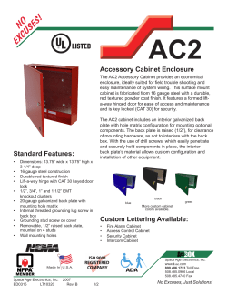


© Copyright 2026