
Microwave Discharge Cavities Operating at 2450 MHz
294
COPELAND,
KUO,
substrate from above and the other on the film from below.
Calibration was accomplished by adjusting the power
input to the lamps until a thermocouple on the substrate
indicated the Curie temperature at the same time a thick
nickel film was at the Curie point. Measurements of the
variation of Curie temperature with film thickness have
also been made.
THE REVIEW OF SCIENTIFIC IKSTRUMENTS
AND
SCHEIBNER
ACKNOWLEDGMENTS
We wish to thank D. E. Lillie for his diligent construction of the glass vacuum chamber. We also want to thank
W. B. Warren and John H. Meeks for their advice on
electronics, W. P. Edmondson and James H. Maddox for
preparing our first films, and Andrew W. Meulenberg, Jr.,
for his help in construction.
VOLUME 36, NUMBER 3
MARCH 1965
Microwave Discharge Cavities Operating at 2450 MHz
F.
C.
FEHSENFELD,
K. M.
EVENSON, AND
H. P.
BROIDA*
National Bureau of Standards, Boulder, Colorado
(Received 27 March 1964; and in final form, 9 November 1964)
Five simple microwave cavities for producing discharges in gases were tested in He and H 2 at pressures from I"
to 1 atm. Three of the cavities are commonly used, and two have been recently designed. One of the newly designed
cavities offered a considerable improvement over early models with respect to compactness, ease of attachment
to the system, and efficiency.
INTRODUCTION
N G the past several years the microwave disD URI
charge has found increasing application as an excitation source for gaseous electronics studies, for light
sources, and for the production of free radicals. This
discharge source has many attractive characteristics:
(1) It produces a high degree of ionization and a large
amount of molecular dissociation without undue heating
of the background gas; (2) with no need for internal
electrodes, it is possible to construct reaction vessels which
are simpler, freer from contamination, and less subject
to damage; (3) it produces little electrical interference;
and (4) the source presents no dangerous high voltage
which can be easily contacted.
Many early sources were fashioned from government
surplus radar equipment but, usually, considerable knowledge of microwave techniques was required to procure
and assemble an adequate system. The need for an inexpensive, uncomplicated source of cw microwave power
was finally satisfied to a great extent through the use of
medical diathermy units which supply a maximum of
about 125 W at 2450 MHz.
The usefulness of this power source rests on the proper
choice of discharge cavities. It is the purpose of this paper
to describe three established and two relatively new cavity
T ABLE I. Ca vi ty characteristics.
Cavity
Electrical
configuration
Tapered rectangular
TEo!,
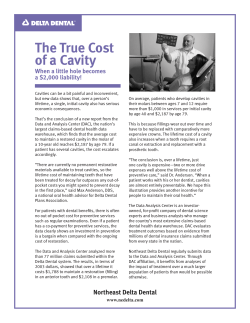
FIG. 1. This photograph shows the relative sizes of the various
cavities. The 13-mm-o.d. Pyrex tubing occupying the position of the
discharge source adds perspective to the picture.
2a
Foreshortened
coaxial
i
2b
Foreshortened
coaxial
i
3
Foreshortened
radial
i
4
Coaxial termination
5
* Present
address: Physics Department, University of California,
Santa Barbara, California.
Foreshortened
coaxial
wave
wave
i wave
Estimated
frequency
range
(MHz)
Removable
from glass
Coupling
discharge
adjustment system
2.45
Yes
Yes
2.3-2.6
No
No
2.3-2.6
Yes
No
2.3-2.6
No
No
0.5-4.5
Yes
Yes
2.0-3.0
Yes
Yes
295
DISCHARGE CAVITIES
TUNING
ADJUSTMENT
ALL PARTS BRASS UNLESS OTHERWISE NOTED
ALL PARTS BRASS UNLESS OTHERWISE NOTED
FIG. 2. A simple drawing of cavity 1.
Scale
FIG. 3. A simple drawning of cavity 2A.
designs and to compare their operation in various gases at
different pressures.
The purpose of the discharge cavity is to transfer power
from the microwave source to the gas, which is contained
in a glass tube. A resonant structure (cavity) is used to
increase the electric field in the gas. To match the impedance of this structure to that of the coaxial line of the
microwave power supply some sort of coupling device is
used. When the resonant frequency of this structure is
tuned to that of the diathermy unit and the impedance is
matched, then the power reflected from the cavity is a
minimum. This minimum value varies with different
cavities. An increase in the efficiency of the cavities is
indicated by a decrease in the reflected power. The presence
of a discharge in the resonator changes the resonant frequency and also changes the loaded Q factor. The properties of the discharge change with pressure and with
different gases; it is therefore necessary to provide both
tuning and matching adjustments to obtain efficient operation over a wide range of discharge conditions. These facts
were not always realized in the development of some of
these cavities, which resulted in the poor performance
noted in these tests.
THE CAVITIES
The five basic cavities which were tested are shown in
2A, designated 2B, the cavities are arranged in chronological order with respect to their development. The object
of all modifications was to produce an effective, compact
discharge source. The progress toward the latter objective
can be seen in Fig. 1. Cutaway drawings of each of the
cavities are shown in Figs. 2-7. The cavities will be discussed individually in order of their listing in Fig. 1.
Some of the basic features of the cavities are listed in
Table I. (Designations of the cavities were obtained from
Ramo and Whinnery,') Table I gives the microwave
configuration of the cavities, the frequency ranges, and
coupling adjustments; and indicates whether the cavity
may be removed from the discharge tube without breaking
the vacuum system.
All of these cavities were designed to produce discharges
in a tube 13 mm o.d., since this size glassware has been
found to be convenient. However, the cavities may be
modified to accommodate larger or smaller discharge
tubes. In each cavity the glassware is located in a region of
strong electric field.
Cavity 1 (Fig. 2) was one of the earliest microwave
excitation sources used in this laboratory.' The slot cut
in the narrow portion of the cavity provides the useful
feature that the cavity may be placed in position and
removed without breaking the gas-handling system. Best
operating conditions usually are obtained when the discharge tube is placed midway along the slot near the edge
(not as shown in Fig. 1). A screw in the coupling probe
permits adjustment of the probe depth to achieve best
coupling.
Cavity number 2A (Fig. 3) has been in use several
years.":" In this cavity the discharge is struck in the gap
between the hollow inner cylinders through which the discharge tube eccentrically slips (see Figs. 1 and 3). The
tuning of the cavity is accomplished by the gap distance
between the varying inner cylinders. In order to obtain a
good, uniform electrical connection between the outer conductor and the variable inner conductor, a Teflon-tipped
1 S. Ramo and J. R. Whinnery, Fields and Wal'es in Modern Radio
(John Wiley & Sons, Inc., New York, 1953), p. 438.
: H. P. B.roida and M. W. Chapman, Anal. Chem. 30,2049 (1950).
M.Zellikoff,P. H. Wykoff,L. M. Aschenbrand, and R. S. Loomis,
J. Opt. Soc. Am. 42, 818 (1952).
4 L. Bovey, Spectrochim, Acta 10, 432 (1958).
: H. E. Radford, Phys, Rev. 126, 1035 (1962).
E. F. Worden, R. G. Gutmacher, and]. G. Conway Appl Opt 2
.,
707 (1963).
'
.
296
FEHSENFELD,
EVENSON,
set screw .has been added. Moreover, setting this screw
prevents detuning the cavity by accidental movement of
the variable inner conductor. The hose fitting on the
coaxial connector allows cooling air to be blown through
the cavity to prevent overheating of the discharge tube.
The hole in the outer cylinder of the cavity permits the
observation of light from the discharge region. It might
be mentioned that the hole in the inner conductor of
this cavity is a waveguide beyond cutoff at 2450 MHz.
Since the plasma is generally confined to the gap region,
this cavity effectively contains the microwave radiation.
Cavity 2B (Fig. 4) is identical to 2A except for the
addition of an adjustable matching stub which is located
on the coaxial connector opposite the hose fitting (see
Figs. 1 and 4). In 2B the tuning is accomplished by the
simultaneous adjustment of the matching stub and variation of the gap distance. Cavity 3 (Fig. 5) is a foreshortened radial line loaded by the capacitance of the i-28
tuning screw.l-? As in 2A, a Teflon-tipped set screw was
provided to obtain reproducible, uniform tuning and locking. Positioning of the off-axis hole was arrived at by a trial
and error method to give the most intense discharge. Tight
magnetic field coupling between line and cavity is achieved
by the large inductive loops. An air hose connection is
(' -,-~:-- DISCHARGE
TUBE
TUNING
ADJUSTMENT
AND
BROIDA
placed on the coaxial connector to provide cooling for the
discharge tube.
Cavity number 4 (Fig. 6) was recently developed.
Change in coupling is accomplished by means of a matching stub located on the coaxial connector. Additional
changes in the coupling can be effected by adjustment of
the shaped probe. A piece of 9.5-mm brass tubing is
located on the body of the discharge source to allow
cooling air to be directed on the discharge tube. The
removable cap permits the unit to be positioned without
breaking the vacuum system. It should be noted that this
cavity is not a resonant cavity in the sense of the other
discharge cavities. While the other cavities were designed
to operate at 2450 MHz and perform only over a limited
band about this frequency, cavity 4 has worked well over
a band width greater than 1000 MHz.
Cavity 5 (Fig. 7) is also of recent development. The
resonant frequency of this cavity is adjusted by means of
the tuning stub and the coupling by means of an adjustable
coupling slider. The wide operating range achieved by this
cavity is due to the presence of both adjustments. In tuning
the cavity with the discharge in operation, the tuning stub
is adjusted for a minimum reflected power with the minimum probe penetration. Next, the probe is adjusted. Since
these two operations are not independent, successive readjustment will improve the efficiency. With a 13-mm discharge tube, optimum tuning is obtained with the end
tuning stub about 5 mm from the discharge tube and the
metal end of the coupling slider located about halfway be-
DISCHARGE _"
OBSERVATION
TUNING
SCREW
MATCHING
/lSIUB
ALL PARTS BRASS
UNLESS OTHERWISE NOTED
o
L
112
I
FIG. 4. A simple drawing of cavity 2B.
7
A. L. Schmeltekopf and H. P. Broida, J. Chern. Phys, 39, 1216
(1963).
o
ALL PARTS BRASS UNLESS OTHERWISE NOTED
112"
Il!
~
Scale
FIG. 5. A simple drawing of cavity 3.
297
DISCHARGE CAVITIES
tween the end of the coaxial line and the tuning stub. In
adjusting the coupling probe, two minima may occur in
the reflected power. Theone corresponding to maximum
coupler penetration is associated with arcing between the
tuning stub and the coupling probe and should be avoided.
Cooling air is directed on the discharge through the tube
located in the body of the source. The removable cap
allows the unit to be positioned without breaking the
vacuum system.
This cavity possesses one design feature which may
require slight modification of the microwave power
generator. To simplify construction, this cavity does not
have a positive de short from the inner coaxial cable to the
outer conducting shield. Most medical diathermy units
require this short before power is supplied to the magnetron.
This is to prevent the magnetron from working into an
open line which would reflect a large amount of power into
the magnetron and shorten its life. To bypass this feature,
the anode of the magnetron may be directly shorted to
ground around the relay. To prevent damage to the magnetron the microwave power supply should be turned off
before one disconnects the cavity.
OPERATING CHARACTERISTICS
In order to provide information on which of these discharge cavities is most effective the following measurements are reported in Table II: (1) the pressure range
between 1 J.L and 1 atm in hydrogen and helium over which
the discharge can be maintained; and (2) the percent of
power reflected from the discharge cavity operating at
pressures of 0.1, 1, 10, and 100 mm Hg. In the pressure
range measurements, the pressure of helium or hydrogen
was allowed to slowly increase or decrease until the
discharge was quenched. Since operating conditions change
I~,
r
TEFLON
TEFLON
ALL PARTS BRASS
UNLESS OTHERWISE NOTED
FIG. 7. A simple drawing of cavity 5.
with variations in pressure, the cavity tuning was readadjusted to maintain a minimum in the power reflected
from the cavity. Since the percent of reflected power over
this pressure range was similar for air, N 2 , O2 , H 2 , Ar,
and He, only the results for He are given in Table II.
The reflected, as well as the incident power, was measured
using a bi-directional power meter located at the output
of the microwave power generator. Usually minimizing the
reflected power produced the strongest discharge for a
given input power. Full microwave power was used in
both tests.
The measurements were made in slowly flowing gases
(1 to 20 atm cc/sec in 13 -mm-o.d, quartz tubing). Pressures above 1 mm Hg were measured with an aneroid
manometer, while pressures below 1 mm Hg were measured
with a heat conductivity gauge. It should be noted that
these measurements were made using reagent grade
cylinder gases. In situations where high gas purity is
maintained or in which different glass tubing is used, the
pressure range over which the cavities operate may be
greatly changed. Accordingly, the results which are quoted
should be considered indicative only. Although in all of the
cavities the discharge may start spontaneously, it may be
TABLE
Cavity
PROBE
ALL PARTS BRASS UNLESS OTHERWISE NOTED
FIG. 6. A simple drawing of cavity 4.
1
2a
2b
3
4
5
II. Operating characteristics.
Pressure range (mm Hg) over which
discharge source operates.
H,
He
High
Low
High
Low
Percent reflected power
in He.
100
0.1
10
mmHg
0.07
0.01
0.01
<0.001
<0.001
<0.001
78
50
46
22
<1
<1
600
>700
>700
>700
>700
>700
0.04
0.03
0.02
0.01
0.01
<0.001
28
240
400
210
250
>450
28
30
5
56
33
<1
4
18
4
63
44
<1
15
10
4
,5
30
<1
298
FEHSENFELD,
EVENSON, AND
initiated over a wider range of pressures with the aid of a
Tesla coil.
In the pressure range measurements, only the results for
helium and hydrogen are given in Table II. However,
similar measurements were made in oxygen, nitrogen, and
air. In the latter gases the discharge could be maintained
in all cavities except cavity 1 to very high pressures.
"Hot spots" in the discharge tube appeared at pressures of
about 400 mm in hydrogen and oxygen and 600 mm in
nitrogen. The presence of the "hot spots" was indicated
by the appearance of the sodium yellow doublet in the
emission spectrum of the discharge. Additional air cooling
of the discharge vessel did not prevent this heating which
could rather quickly melt the glassware. Heating was not
observed in the rare gases, indicating that this effect was
probably due to wall recombination.
Cavity 1 was found to be useful over a limited range of
pressures in comparison with other cavities. This cavity
was found to operate between 0.003 and 48 mm Hg in
nitrogen, and between 0.002 and 82 mm Hg in oxygen.
In both these gases, the other cavities maintained a discharge from less than 0.001 mm Hg to the pressure at which
"hot spots" developed. In addition, even in the rare gases,
large amounts of power were reflected because of an
inadequacy of the tuning adjustments. Due to its cumbersome size and its relatively poor performance, cavity 1 is
now seldom used in our laboratory.
Cavity 2A may be operated over a much wider range of
pressures than 1. It gives satisfactory performance with
oxygen, nitrogen, and hydrogen, operating at high pressures. This cavity operates most efficiently when the gas
pressure is above 1 mm Hg. In cavity 2B the addition of
the matching stub to this cavity considerably enhances its
efficiency and extends the range of operation. This cavity
is not as convenient to use as 4 and 5, nor as efficient as 5.
Cavity 3 operates over as great a range of pressures in
the various gases as 2B. Cavity 3 operates most efficiently
at low pressures. The measurements indicate the operation
of 3 in the low pressure region to be somewhat better than
2B, while the reverse is true in the high pressure region. At
higher pressures, the discharge is confined to a region close
to the wall of the discharge tube nearest the coupling loop.
In this region, heating of the glassware again was observed
at high pressures. This cavity is about as convenient in
use as 2B.
Cavity 4 operates over a range of pressures as great
as cavities 2 and 3. This result is shown in Table II. The
matching adjustment arrangement is adequate, however,
only at low pressures as shown. While 4 is as convenient
to use as 5, it is not as efficient over as wide a range of
pressures.
Cavity 5 exhibits the widest pressure range for operation
and is nearly 100% efficient over this entire range. The
BROIDA
high pressure limitation of the operation of this cavity in
H 2 was imposed by the fact that the cooling used could
not prevent the quartz discharge vessel from melting. A
strong discharge was produced by this cavity in low pressure hydrogen which was characterized by a spectrum
consisting principally of emission from atomic hydrogen
indicating its possible use as an atomic hydrogen light
source.
In the preceding discussion five types of discharge
cavities have been described. In each case the Q's of the
cavities are relatively low « 1000). Their effectiveness
arises from the fact that the cavity containing the discharge
can be well matched to the microwave power source. In
over-all ability to produce a discharge in a wide variety of
conditions, cavity 5 has proved to be most effective.
Cavity 5 also is more convenient to use than 1 through
3. In all cavities except 1, a discharge could be maintained
over a pressure range from about 1 IJ. to near 1 atm for
even such gases as N 2 , O2, and H 2 • Cavities 3 and 4
performed somewhat better at pressures less than 1 mm Hg
while cavity 2 gave better results at pressures above 10
mm Hg. The operation of cavity 5 was superior over the
entire range of pressures. Thus cavity 5 offers a considerable improvement over earlier models in all important
respects.
In general, the optimum tuning for initiation of breakdown does not correspond to the optimum tuning when the
discharge is in operation. Careful tuning is advisable since,
aside from the advantage derived from a strong, steady
discharge, the deleterious effects of the reflected microwave power on connecting cables and the microwave power
source is reduced. Optimum performance of all of the
cavities is achieved only when good electrical contact is
maintained in the various tuning adjustments and between
the coaxial line and the cavity.
Fairly large amounts of microwave power may be
radiated from these sources when the discharge is in
operation. In fact, in all sources except 2A and 2B, a
discharge may extend several centimeters in the tube
outside the cavity. For applications in which stray radiation is objectionable or hazardous.s-" the addition of
shielding sleeves along the discharge tube should prove
worthwhile (household aluminum foil is quite satisfactory).
Many of the cavities described here have been used for
several years by our colleagues, and we are very much
indebted to them for their valuable comments, assistance,
and suggestions."
The support of the Advanced Research Projects Agency
and the Defence Atomic Support Agency is gratefully
acknowledged.
8 A. F. Harvey, Microwave Engineering (Academic Press Inc., New
York, 1963), p. 973.
• W. W. Mumford, Proc. IRE 49, 427 (1961).
10 Detailed working drawings of the cavities are available from the
authors.


© Copyright 2026