
Raspberry Pi 8 LED Breakout board kit
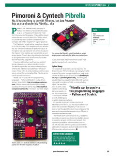
Raspberry Pi 8 LED Breakout board kit
www.MaximumOctopus.com/electronics/piled8.htm
You’ll find the latest versions of the instructions and example source code at the address above.
Thank you for purchasing the Raspberry Pi LED 8 board! I hope you have lots of fun with it!
If you have any suggestions for future boards then please let me know. I’ll send you some free boards if I like your
idea!
Maximum Octopus Limited
Kit Contents
This kit was put together by a team of highly skilled octopuses; it should contain the following items:
1)
2)
3)
4)
5)
The main PCB (23.8mm x 23.4mm)
8x 3mm LEDs
8x 100Ω resistors
1x 0.1uF capacitor
1x 26 pin header
Important Things to Remember
This kit is designed to be used with any Raspberry Pi Model B, B+ or 2. Always be very careful when
attaching the board to the Raspberry PI, taking care not to bend any of the header pins. ALWAYS place this
LED 8 board so that the left most pins (those closest to the capactitor), pins 1 and 2, are connected to the
Raspberry Pis pins 1 and 2 with the LEDs covering part of the the Raspberry Pi main PCB.
Before soldering any components check and then double-check that they are correctly oriented.
Don’t rush, and have lots of fun!
If you need a good tutorial on soldering then SparkFun Electronics has a good one
(https://www.sparkfun.com/tutorials/106) as does Adafruit Industries
(http://www.ladyada.net/learn/soldering/thm.html).
Maximum Octopus Limited
Building Instructions
You will need a soldering iron, solder, an octopus (or a set of handy helper things) and wire cutters. To keep some of
the large components in place while soldering you might find Blue-Tac useful to stop them moving around or falling
off.
Take your time and check the placement of every component before soldering them in place!
STEP 1 – The 26 pin header
The PCB sits on “top” of the header’s pins, so that the pins are visible at
the same time as the Maximum Octopus logo.
STEP 2 – 8x 100 ohm resistors
The resistors should be soldered next, place them so the main body
of the resistor sits on the top of the PCB. Once they’ve all been
soldered in place you’ll need to trim the leads using a pair of wire
cutters.
STEP 3 – The LEDs
Solder each of the 8 LEDs next. The long lead (anode) goes in the hole
closest to the resistor (the short lead (cathode) goes closest to the
edge of the PCB).
STEP 4 – Socket
The IC socket goes next. This is optional; you might like to solder the shift register IC directly to the board (like in the
picture at the beginning of this document).
The IC should be positioned on the board so that the “notch” faces C1 (the location
of the capacitor).
STEP 5 – The Capacitor
The orange (or yellow) capacitor is placed in position C1, at the “front” of the IC. It is
not polarised, it can be placed any way around.
Maximum Octopus Limited
If you decided to socket the shift register IC then now it’s time to place it in to its socket. It should be socketed so
the notch on the chip is on the same side as the notch on the socket – facing the 0.1uF capacitor.
Before you try to carefully slot the chip in to socket you’ll notice that the legs are spread out too much to fit. They’ll
need to be bent inwards before they’ll fit. DO NOT FORCE IT.
The way I like to do this is by very carefully pressing each side of the chip on my desk until both sets of pins are
parallel. Once the legs are parallel it will take a bit of force to push the chips in to the sockets, be gentle and patient.
On the website, at the address at the top of this document, you’ll find many example programs for the Raspberry Pi
to get you going.
Start off with example1.py, then once you’re happy with how it works try the other, slightly more advanced.
programs.
Have fun!
Maximum Octopus Limited
Schematic
Maximum Octopus Limited
Example source code for the Raspberry Pi can be found here: www.MaximumOctopus.com/electronics/piled8.htm
If you have any comments or suggestions for this kit then please let us know.
For more information, updates and details of new kits check out the following links:
Website
www.MaximumOctopus.com
Twitter
http://www.twitter.com/maximumoctopus
Blog
http://maximumoctopus.wordpress.com
Online store
http://store.MaximumOctopus.com
YouTube
https://www.youtube.com/user/freshneyorg
This kit was designed and manufactured in the UK.
(c) Maximum Octopus Limited 2015
Last update: March 17th 2015


© Copyright 2026