
Pre-purchase Condition report on: Jeanneau Sun
Pre-purchase Condition report on:
Jeanneau Sun Odyssey 34.2 Magician
For:
Mr Les Knowles
Member
Royal Institution
of
Naval Architects
Richard R Thomas BA(hons) MRINA T/A Medusa Marine
236 Walton Road, Walton on the Naze, Essex, CO14 8LT
01255 674074 – 07831160402 – VAT Reg No. 720 3281 75
email [email protected] www.medusamarine.co.uk
Survey Report Magician
Condition Survey Report on Yacht Magician
This survey was carried out on the instructions of:
Mr Les Knowles
371 Amersham Road
Hazlemere
High Wycombe
Bucks HP15 7HR
Contents
Page
1) General notes
2
2) The vessel specifications
3
3) Survey details
a)
b)
c)
d)
e)
f)
g)
h)
i)
j)
k)
l)
m)
n)
o)
p)
q)
r)
s)
t)
u)
v)
w)
x)
y)
z)
Hull general
Bottom
Topsides
Hull deck seam
Deck
Superstructure and cockpit
Hatches & companionways
Windows & ventilators
Deck gear and fittings
Safety equipment
Skin fittings & seacocks
Engine
Fuel system
Stern gear
Steering system
Mast, spars and standing rigging
Sails and running rigging
Sea toilet and heads compartment
Fresh water system
Galley
Electrical system
Gas system
Fire fighting equipment
Bilge pumping
Interior fit-out
Additional equipment
5
5
7
8
9
10
11
12
12
14
14
16
17
17
18
19
20
21
22
22
23
24
25
25
26
27
4) Summary of recommendations
28
5) Conclusions
29
Appendix
Page | 1
Explanatory Notes
30
Survey Report Magician
1) General notes.
a) Responsibility
Any responsibility is to the above client only and their insurers, and not to any
subsequent owner of the vessel under survey or holder of this report.
Copyright is retained by Medusa Marine and copies must not be made or
distributed without specific permission of the copyright holder.
b) Location
The vessel was laid up ashore at Suffolk Yacht Harbour, Levington, Ipswich,
Suffolk, IP10 0LN, on the 19th January 2015
c) Purpose and scope of survey
This survey was commissioned by the prospective purchaser for the purpose
of establishing the condition and value of the vessel prior to completion of the
sale. Unless otherwise stated, the vessel was not surveyed for compliance
with any build standards (RCD) or operational codes of practice or local
licenses. The vessel has also not been surveyed for suitability for any
particular purpose or location. This survey report is a factual statement of the
surveyor's examination as carried out and his opinion given in good faith as to
the relevance of disclosed facts and defects so far as seen. It implies no
guarantee against faulty design or latent defects.
d) Limitations
Areas inspected were limited to openings and access available during normal
operations and maintenance of the vessel. No fastenings or skin fittings were
removed, keel bolts drawn or joinery or head linings removed. Closed
compartments were visually inspected by means of a Ridgid CA100
endoscopic camera. Materials used in the construction were tested as far as
was possible by industry standard Non Destructive Test (NDT) test
equipment.
Unless the vessel was afloat, the mechanical condition of the engine was not
covered by survey, only the installation and components normally available to
routine maintenance could be assessed. If afloat, only assessment of the
engines no load running condition was possible. Sails where present, were
examined for general condition. The sails were not set, so no assessment of
shape or stretch could be made. Spars where stepped were examined from
deck and ashore only.
Navigational equipment, electrical installations and domestic appliances were
assessed subject to limitations if battery charge or shore power was available.
If there was no opportunity for sea trialling the vessel, no assessment of the
vessel and her equipment under seaway conditions was possible. No opinion
Page | 2
Survey Report Magician
could be made or responsibility undertaken for condition or defect of those
aspects of the vessel not accessible or evident due to the above limitations.
e) Recommendations
Recommendations have been subdivided into three categories. All
recommendations are annotated thus and are summarised at the end of the
report
Category 1 (Cat 1) are safety related defects which should be corrected
before the vessel is put into commission.
Category 2 (Cat 2) recommendations relate to defects which affect the
operation of the vessel in normal use and should be attended to at the earliest
opportunity. They do not however, affect the safe operation of the vessel.
Category 3 (Cat 3) recommendations relate to conditions which are cosmetic
or may affect the perceived value of the vessel and should be attended to in
the next lay-up season.
2) The Vessel specifications and description
Note: Dimensions and measurements given have been derived from
manufacturers published data, and have not been verified by survey.
Dimensions:
LOA:
LWL:
Beam:
Draft:
Displacement: (light)
Ballast:
Manufacturer:
Model or Type:
Year of Build:
HIN No.
SSR No.
Designer:
Construction:
Engines:
Main sail area
Head sail area
10.29 metres
8.99 metres
3.28 metres
1.40 metres
4.651 tonnes
1.520 tonnes
SPBI Jeanneau SA
Sun Odyssey 34.2
1999
FRA-IRI00357A999
SSR 109192
Jacques Fauroux
GRP hull and deck
1 x Yanmar 3GM30F
244 sq ft
229 sq ft
This vessel was built after the 16th June1998 and therefore is subject to the
requirements of the Recreational Craft Regulations (SI 1996/1353). It was
built before the 2005 (Directive 2003/44/EC) which included environmental
emission limits.
Page | 3
Survey Report Magician
Vessels that have evidence that they were in use as private pleasure craft
prior to 1 January 1985 and were in the EU on 31 December 1992 are
deemed VAT paid. This vessel was supplied new within the UK after those
dates but no evidence of the VAT paid status was seen on board at the time
of survey. This should be established by the prospective purchaser prior to
completion.
The Jeanneau Sun Odyssey 34.2 is one of the more successful models built
by the Jeanneau company which is part of the Beneteau Group, and is itself
one of the largest boat builders in the world. The design was pitched firmly at
the Mediterranean charter market and some yachts were also branded as the
Stardust 342 and Stardust 343, the final digit denoting the number of sleeping
cabins..
The hull form of the 34.2 looks similar to other modern production boats of the
same period with minimal overhangs, little flare or tumblehome, and a reverse
transom. The generous beam is carried well aft with a flat sheerline and a
rakish semi flushed in coachroof.
Underwater the canoe body features a shallow forefoot and flat underbody
sections which will lead to some slamming upwind in a seaway The optional
shallow fin and bulb keel is epoxy-coated iron with a modest ballast ratio of
32.6%. However, the the low centre of gravity with a bulb foot to the keel will
give a good metacentric height and fairly stiff righting moment.
Below decks this model is the two cabin version with the layout optimised for
two cruising couples. There are two generous double cabins but the
specification gives berths for six. This includes the saloon dinette to starboard
converting to an extra double.
The forward cabin has a double V berth and a hanging locker to starboard. To
port is additional storage. The main saloon has an oval table with long curved
settee outboard and a clever sliding seat inboard. This table can drop down to
form another double berth. The galley takes all of the port saloon side with
generous worktops and large double sinks. Aft of the saloon settee to
starboard is the navigation station with a full sized chart table and a dedicated
navigator seat. Abaft the galley is a good sized heads and shower
compartment. This is designed as a wet room with a wet locker aft and a
sump pump out in the sole. The engine compartment is under the
companionway steps with a hinging cover in the aft cabin for good access to
the engine.
The aft double cabin has an off centred double berth and hanging lockers and
good access to the stern gear. Above the aft cabin is the cockpit. This has
seating in a U with a walk round steering pedestal and a removable step
through transom to the sugar scoop. There is a shallow cockpit locker to
starboard and a cavernous full depth locker to port which incorporates a
dedicated gas locker.
Page | 4
Survey Report Magician
3) Survey details
a) Hull general
Hull construction is of solid skin glass reinforced plastic (GRP) laminates of
woven rovings (WR) and chopped strand mat (CSM) bonded with polyester
resins. The actual construction is quite light at just over 4 ½ tonnes for her
length and beam but the construction includes laminations of Kevlar for
stiffness and strength. Kevlar is a para-aramid synthetic polymer with many
times the strength of glass or steel. The hull strength and stiffness is
enhanced below the waterline by a substantial matrix of longitudinal and
transverse stringers moulded to the hull internally and the whole is considered
to be of sound design and manufacture.
This hull would have been built long after the problems associated with
moisture absorption into permeable resins and laminates were fully
understood. The actual resins used in the construction could not be
determined, so no assumptions could be made. Extensive moisture readings
and hammer testing done was done externally and also internally where
possible by internal joinery. These results were annotated and recorded.
b) Bottom
The bottom is finished with blue anti-fouling paint which was well adhered. It
appeared an old application as it was eroded significantly. The hull was
sounded all over with a small pin hammer and was found to be free of
delamination or voids. It was also moisture tested and found to be of an
acceptable level and there was no visible blistering.
Some antifouling paints with high metallic components can affect moisture
readings. The antifoulings extended about 10 cms above the waterline, so
readings were taken for reference on the topsides and through the antifoul
above the waterline and the results were consistent. This indicates that the
antifouling paint had no effect on the moisture readings, so no areas were
scraped back to gel coat. Where this can be avoided it is beneficial in
preventing any damage to any preventative epoxy coatings.
Moisture readings were taken with a Sovereign Quantum Marine Moisture
meter. This meter is a capacitance type tester and is equipped with both deep
and shallow reading scales. This is useful to trace the depth of penetration of,
and correspondingly the drying out of moisture. All polyester laminates will
absorb some moisture to a degree without it effecting the structure or strength
of the construction. The two scales can also be used to eliminate spurious
readings generated by condensation or metallic components inside the bilges.
The comparative scale is 0 to 100, which is an arbitrary scale, and does not
Page | 5
Survey Report Magician
represent actual percentages of moisture in GRP. Thus figures are thus
quoted as scale readings and not as percentages.
Representative readings on a Sovereign Quantum comparative scale for
moisture content in GRP laminates approximate as follows:
0-15
Regular readings for a ‘dry’ GRP laminate
16-20 Slight absorbsion typical of permeability of weather exposed GRP
20-30 Medium moisture content, could be osmotic but unlikely to blister
31-45 High moisture, osmotic process but not necessarily physical effects
46-60 Very high, usually physical effects, blistering and wicking evident
61-100 Extreme saturation moisture with a visible structural defects
The atmospheric conditions at the time of survey were as follows:
Weather:
Wind:
Air temperature:
Hull surface temperature:
Relative Humidity:
Dew point:
Hull temp over dew point
Cloudy sky with occasional sunshine
S 3 / 5 kts
37°
4.5° (stbd) 4.7°(port)
56.4%
- 6.2°
+ 10.8°
It is usually considered necessary for the hull temperature to be at least 5°
above the dew point for moisture readings to be representative.
Readings were taken in the topsides and showed a consistent level of 5 to 7
on both the deep and shallow scales. Readings were taken in the antifoul
above the waterline and showed readings of 6 to 8 on both the shallow and
deep scales.
The area immediately below the waterline showed average shallow scale
readings of 15 rising to 16 or sometimes 17 in certain areas. These readings
increased slightly toward the keel resulting in final scale readings of around 21
by the keel. Deep scale readings were consistently lower over the whole area
at 10 to 12.
Examination internally showed similar readings when tested in corresponding
places to the external examination. The area alongside the keel was distinctly
high at deep scale 30 but the shallow scale readings were normal to the
surrounding areas and there was evidence of extensive surface moisture due
to condensation inside the hull at this point. The high readings around the keel
can be attributed to the meter reading the internal moisture in the bilges and
can therefore be discounted.
Overall the hull bottom is considered to have an acceptable and natural level
of water absorption in the shallow laminates and negligible absorption in the
deeper laminations. The levels are too low to cause damage or lead to any
decomposition.
Page | 6
Survey Report Magician
The general condition of the hull bottom is good and a regular routine of laying
up on hard standing for a couple of months every season should prevent any
chance of the hull suffering any physical degradation. This preventative
routine is good practise for a hull of this age. (See explanatory note 1)
The keel is a grey iron casting of a foil shaped appendage with an integral
cast bulb at the foot. This casting is generally good but there are very small
areas of light corrosion around the leading and trailing edges and under the
bulb. This is almost certainly due to natural abrasion having broken the
coating of epoxy paint which would have been applied. These areas should
be treated and re-coated.
Recommendation
(Cat 2) Abrade the keel locally to the corrosion, preferably by sand blasting,
and treat with a rust converter and apply epoxy coatings.
The keel landing seam is good with no signs of weeping of rust stained water
or failure of the sealant. The keel bolts were tested with a magnet and found
to be mild steel with substantial mild steel backing plates. This is good as
steel is significantly stronger than stainless steel and not subject to corrosion
stress cracking. These fastenings are flo-coated over and although there has
been some failure of the coatings there is little evidence of corrosion.
There is a large pear shaped hull anode fitted in the port side aft hull bottom.
This is 10% eroded. A continuity check was made between it and the stern
gear and no resistance could be recorded. For full efficiency of the cathodic
protection, a resistance of less than 1 ohm should be recorded.
Recommendation
(Cat 2) Replace the hull anode and check the bonding system resistance after
fitting to ensure it is below 1 ohm resistance.
c) Topsides
The topsides are constructed of solid GRP laminates with white coloured gel
coat finish. There is a blue double boot top strip in a spray gel and a blue cove
line stripe in vinyl tape.
The hull is reasonably fair with only very slight distortion visible from bonded
in internal structures. These are bulkheads and stringers. There is negligible
damage evident and overall the hull surface is in very good cosmetic
condition. Close examination shows extensive spots of gel coat repairs on the
port side at the maximum beam. This is assumed to be docking damage from
a ‘port side to’ pontoon berth as the starboard side is spotless. These repairs
have been very well executed and are invisible to all but minute examination.
Page | 7
Survey Report Magician
The topsides were tested with a Barcol Impresser. This tests the hardness of
the laminate and so in theory establishes the consolidation of the lay-up and
the level of cure of the resins. These readings can vary so up to 30 readings
were taken around the hull and were averaged to produce a mean of 47 HBa.
This averages out well above the normal range, (38 to 40 are considered
satisfactory for marine grade isothalic/orthothalic resins). The Impresser was
calibrated before and after testing with check samples and found to be
accurate.
These readings were ideal and would normally be seen as evidence that the
hull lay-up was well consolidated and at a good level of cure. The higher than
normal readings could be indicative of two factors. Woven rovings could be
used in the first layup as the cloth / resin ratio is higher at 50:50 compared
with 40:60 typical of chopped strand mat. Also some specialised resins such
as ‘low styrene’ Polyesters and Vinylester resins have higher Barcol hardness
rates. No assumptions could be made of the exact cause but both reasons
are beneficial. Woven rovings are not prone to wicking as there is no emulsion
used to bind the fibres as in chopped strand. Low styrene resins and
vinylester resins are less permeable than standard isothalic polyesters.
The hardness and cure state of the gel coat is tested with a Shore D
Durometer. This will also show any progressive softening due to oxidisation.
Readings ranging from 92.0 to 93.5 HSD where made, which are good. (88 to
90 is considered normal). The readings on the transom were slightly lower at
89.5 to 91.0 which indicates that the vessel may have been berthed with the
transom exposed to the full sun from the south. These high readings indicate
that a high gloss level cab be achieved when polished. Overall the tests show
a well specified and well executed hull construction.
Recommendation
(Cat 3) Protect the topsides gel coat from any degradation using polishes
containing PTFE compounds. These will provide the same UV protection as
silicones, but they do not have the propensity to migrate and cause
subsequent refinishing and embrittlement problems. (See explanatory note 2)
d) Hull to deck seam
The hull has been moulded in a split mould and the hull to deck seam is
achieved by the hull moulding having a moulded inward facing flange. The
deck moulding is then landed onto this flange with sealant and through
fastened by the screws which secure the toe rail in place. The external joint is
covered by the extruded aluminium toe rail. This joint is visible in the aft
lockers. The joint has not been laminated over internally but examination did
not reveal any signs of movement or leakage in the joint where it was visible.
The seam is carried then round the lower edge of the transom where it is
capped by a rigid PVC extrusion. This was sound and in good condition.
Page | 8
Survey Report Magician
It is evident that the deck was fully assembled with all the deck furniture fitted
before the deck was installed. The hull flange has had rebates cut out to
provide clearance for the fastenings for the mooring cleats etc. The only
mechanical fastenings through the seam are the screws for the toe rail and
the bolts for the stanchions. This is a common practise among volume boat
manufacturers where the deck and hull are manufactured on separate
production lines and are joined in the final assembly process. By this method
there is no access for subsequent fastening or bonding as the joint is hidden
behind already installed joinery. This method of assembly is adequate in
normal use, and has been proven so by the thousands of boats manufactured
worldwide by this method. It is however vulnerable should the joint receive a
substantial impact and if such should happen it is important that the damage
is thoroughly examined internally for splitting, opening up or leakage. This
would necessitate the removal of internal joinery.
e) Deck
The deck is constructed from solid and cored GRP laminates. The deck is
moulded with a pyramidal non-slip texture which is in good condition and little
sign of chipping of the raised profile. The deck laminate skin was sounded by
pin hammer where possible and found to be well bonded to the core but the
core material could not definitely be established without taking core samples
which is outside the scope of this survey.
The deck moulding was tested for moisture in the laminate and in the core
material. Moisture readings were taken with a Tramex Skipper Plus Marine
Moisture meter. This meter is also a capacitance type tester but is preferable
to the Sovereign Quantum in this application as it uses soft rubber pads for
the sensors and gives better results on textured surfaces. It is also has wider
spaced sensors and can read deeper through thick cored decks.
Representative readings on a Tramex Skipper Plus are different to the
Sovereign Quantum and the comparative scale for moisture content in GRP
laminates approximate as follows:
0-15
16-38
39-65
66-100
ranges
Regular readings for a ‘dry’ GRP laminate
Slight absorbsion typical of permeability of weather exposed GRP
Medium moisture content, could be osmotic but unlikely to blister
High moisture with a possibility of physical degradation at higher
Readings of 15 to 20 were recorded over the majority of the deck with very
slight elevation around some deck fittings. Particular attention was paid to
areas where the chain plates were bolted through the deck. Readings on the
port side chain plate were particularly high at 75 on the comparative scale in
just one small area outboard and slightly forward of the chainplate. On the
corresponding starboard side the readings were also raised but not to the
same degree at 40. Readings could be taken internally but after removing
deck head linings it was found that the GRP deck head moulding covered the
Page | 9
Survey Report Magician
affected area. These readings indicate that there was probably moisture
absorption within the deck core. Common core materials are either end grain
balsa or vinyl foam and both are equally subject to moisture absorption
through leaking deck fittings. Although the foam is described as ‘closed cell’
there is actually no such thing, some foam cell structures are just more closed
than others. In this instance the core material appears to be particularly well
bonded to the skins and so is probably end grain balsa.
Internally the chain plate is bolted to a tie rod which transfers the rigging loads
to the hull structure below at the intersection of a vertical ring beam and
horizontal stringer. This tie rod passes through a plastic panel in the
headlining. Removing this panel provided no evidence that the chain plate has
been leaking through to the accommodation. There was no water staining on
the inside face. This chain plate, and the starboard one, should be re-bedded.
This is not a major operation and can be done without un-stepping the mast.
Recommendation
(Cat 2) Remove and re-bed port and starboard chain plates.
Sounding the underside of the deck with a hammer where accessible showed
no sign of the deck moulding having separated or de-bonded from the core
material. Externally tap testing with a hammer showed the same good results.
It is not recommended that anything is done at this stage about the moisture
in the core provided the cause is remedied now. Rectification would be very
intrusive and the moisture at present is localised and does not compromise
the integrity of the structure.
At the bows there is a large anchor locker which has a hinging GRP lid with a
raised forward profile to allow for the shank of an anchor which would be
stowed on the bow roller fitting. Abaft the locker within the same recess is a
Goiot anchor winch and the locker lid has a raised central profile to allow for
the height of the windlass. This is well seated and in good condition although
it was not tested. The anchor locker drains through a skin fitting in the
starboard topsides.
f) Superstructure and cockpit
The coachroof superstructure and cockpit are all integral with the deck
moulding. The coachroof top features the same non-slip moulded texture as
the deck and is also in good condition with no sign of chipping of the raised
profiles. The coachroof is semi flush at the forward end where it blends into
the deck. Set upon the after end of the coachroof are two teak rails under
which the hatch slides. The hatch runs on rubber seals in moulded drainage
channels which divert any water running off the hatch into the cockpit.
The cockpit seat tops have been laid with a teak with polysulphide caulking.
There are no teak margins which indicate that this deck is a ‘kit’ deck where
the teak has been pre made in sheets bonded to a thin plywood or epoxy
Page | 10
Survey Report Magician
scrim substrate and cut to profile. These are in good condition with the teak
having suffered from only a little erosion, and are an attractive silver tan
colour. (See explanatory note 3)
The cockpit sole is also finished in the same non-slip profile. There are two
lockers within the cockpit seating. The main locker is to port where it is full
depth and contains the holding tank and the dedicated gas locker both of
which are detailed elsewhere. The starboard locker is shallow as it is above
the aft cabin and is just for general stowage. It also contains the shore power
installation. The lids to all these lockers are hinged and are without stays.
Lanyards with plastic hooks are provided to secure them open. The lids are
secure and the lanyard system works satisfactorily. The hatch latches have
been altered from original. Standard fitments are piston latches which engage
into hasps. These are prone to damage with use. The pistons have been
removed and new toggle type latches have been fitted in another position.
The redundant hasps have been retained and rope loops have been fitted to
give easier grips for opening. This is an improvement over the original
arrangement.
Abaft the helm is a helmsman’s seat which is a separate moulding which lifts
up and down to allow access to the boarding steps aft. This is not retained
and could be lost overboard. Under the seat is access to the top of the rudder
stock and provision for emergency steering. There are no cockpit drains and
the cockpit is open to the transom under the helm seat for drainage.
On the top of the coachroof is an alloy casting set in a small moulded plinth
onto which the mast is stepped. Supporting the mast step beneath is a
substantial stainless steel compression post which is stepped onto the
forward most keel floor. This does not appear to have been depressed and
has not been deflected downward relative to the surrounding sole boards.
Neither is the coachroof showing any signs of compression.
g) Hatches & Companionways
The companionway is closed by a sliding hatch and a washboard. The hatch
is a single piece of 10mm acrylic with an acrylic bonded flange at the after
edge as a hand rail. This is in good condition and the acrylic is un-weathered
and the hatch slides easily. The washboard is also acrylic and locates under
the hatch flange at the top and closes at the bottom with a sash lock which
engages into a slot in the bridge deck. This is all in good condition and is
secure.
On top of the coachroof is a large 500mm square aluminium framed hatch
manufactured by Gebo. This hatch effectively forms an escape hatch from the
forepeak and is hinged on the after edge. This is not ideal as it does not
prevent a breaking wave from flooding the forepeak if the hatch is not fully
closed. There is also a possibility of the hatch being carried away in a storm.
The fore hatch appears to be fairly watertight with no signs of leaks or water
Page | 11
Survey Report Magician
tracking. The acrylic is good with no crazing evident that would make it unsafe
to walk on. If the vessel is to be used for offshore passages it is
recommended that the hatch is reversed so that it hinges on the forward
edge.
Recommendation
(Cat 1) Consider removing and reversing the forward hatch if using the vessel
for extended offshore passages.
Aft of the mast is a similar hatch also by Gebo, which is hinged at the forward
edge. This is in similar good condition with no signs of leakage as the saloon
table beneath is unmarked. Both hatches have fly screens fitted and also
blinds manufactured by Lewmar which are in good condition.
h) Windows and ventilators
There are six windows in the coachroof, four each side equally disposed
around the saloon. The aft most two each side are inward opening portlights
by Gebo The glazing is in acrylic and is clear and undamaged. The aluminium
frames are anodised and in good condition. There are no signs of leakage or
water tracking stains on the inside. All of the opening windows are of the
inward opening type. The forward pair of windows are fixed toughened glass
windows framed in aluminium and styled to the shape of the coachroof. These
are also watertight with no signs of tracking water stains.
In the topsides, giving light to the forepeak, aft cabin and the saloon are five
fixed deadlights also by Gebo. Two are on the port side and three on the
starboard side. These are also watertight and in good clear condition. The aft
cabin has the benefit of an additional opening portlight into the cockpit. This is
also by Gebo and is in good condition.
There is no additional ventilation to the saloon other than the opening
portlights and holes through the washboard. In the forepeak there is a Goiot
dorade ventilator installed in the glazing to the hatch. These can be prone to
leaking unless they are mounted within a few degrees of horizontal, but this
installation appears watertight.
i) Deck gear and fittings
A pair of stainless steel T bar sheet tracks by Amiot is mounted on the outside
edge of the coachroof. Each carries a stand up sheet block with alloy sheaves
and side rollers for sheeting the genoa. These blocks slide on cars and are
limited in their aft movement by stops with spring loaded pins locking into
holes in the track for adjustment. These slide well and are in good functional
condition. The sheaves show no signs of flat spots starting to wear. When flat
spots form the sheaves cease to rotate and the resulting friction on the sheet
will damage and weaken the rope
Page | 12
Survey Report Magician
A pair of cast alloy mooring cleats is mounted either side at the bows. There is
a second pair amidships and a third pair on the aft quarters. All are well
secured and in good condition. There are no fairleads associated with the
midships and aft cleats. The stemhead fitting incorporates fairleads for the
forward cleats. All the cast alloy deck fittings are anodised and are lightly
oxidised. The cast alloy stemhead fitting also incorporates a double bow
roller, one roller to port is shaped for warp the starboard roller is shaped for
chain and stowage of the anchor shank. The stainless steel forestay fitting
passes through this fabrication. All appeared in good condition but could not
be tested for effectiveness.
The mast step casting has 9 stand up blocks which feed the halyards and
reefing lines back to the clutches via Barton deck organisers. There are 6
organiser each side in two banks. All these were sound and in good condition.
Two primary winches are mounted either side of the companionway on the
coachroof. These are self tailing two speed Harken 40’s and are in good
cosmetic condition. Forward of these on the coachroof top either side of the
companionway is a pair of self tailing single speed Harken 16’s also in good
cosmetic condition, none of the winches could be tested under load. The
ratchets sounded clean and firm but it is always recommended to service
them if the service history is not known. Winch sizes are based on power
gearing and not physical size. (See explanatory note 6)
Recommendation
(Cat 1) Service the winches and replace the pawl springs.
On the coachroof top ahead of the secondary winches are two banks of
clutches. On the port side are three Spinlock XT and three XS clutches. On
the starboard side are six Spinlock XS clutches These were examined for
wear on the teeth of the cams and bottom plates but all were in good little
used condition. The XS clutches are probably the original specification and
the three XT’s have been upgrades as the holding power of the smaller
clutches are inadequate for running rigging loads on this sail plan.
The main sheet block by Amiot is set on a track across the coachroof forward
of the main hatch. This track is controlled by a pair of purchases which are fed
back to a pair of Spinlock PXR clutches. The main sheet is fed forward to the
gooseneck and mast step and then back via a deck organiser to the winch.
The track is well seated and secure but the sheeting system could not be
tested for operation. On the outside of the coachroof coamings is a pair of
Spinlock cheek blocks with jammers. These are for the genoa sheets to feed
to the primary winches. They are well seated and in good condition with no
flat spots occurring on the alloy sheaves.
Mast shrouds are pinned to chainplates which are fastened through the deck
to plates in the deckhead which have tie rods attached which transfer the
loads to the hull structure beneath. These appear well seated although the
plates appear to be leaking slightly as detailed elsewhere. There are
Page | 13
Survey Report Magician
additional plates forward which secure a pair of forward lower shrouds. These
are also well secured. There is no corrosion staining visible where they pass
through and are fastened under the deck head. Any evidence of significant
hidden corrosion in load bearing stainless steel components must be
investigated as a matter of urgency. (See explanatory note 6)
j)
Safety equipment
The vessel is equipped with a tubular stainless steel pulpit and twin pushpits.
Tensioned between is 4mm 1 x 19 plastic coated upper and lower stainless
steel guardwires with roll swaged end fittings and rigging screws for
tensioning. The guardwires are continuous. The pulpit and pushpits are in
good condition and well secured into the deck. The guardwires are in
reasonable condition with only a little rust staining where the wire emerges
from the coating at the ends by the terminations. There are also some breaks
starting to wear in the plastic coating and some corrosion staining where they
pass through the stanchions. The plastic coating can accelerate anaerobic
corrosion in stainless steel and it is recommended to routinely replace
guardwires after 10 years. These guardwires have some life left in them but a
routine check should be made at the vulnerable sections where they pass
through the stanchions and replace when necessary.
There are four stainless steel stanchions each side socketed into cast
aluminium stanchion bases bolted through the deck and toe rail. There is
some movement between the stanchions and the bases, but the bases are
well seated and secure.
There are 2 harness strongpoints fitted to the cockpit sole. These are folding
pad eyes and one of these hooking points is within easy reach of the
companionway. On the coachroof top there is a pair of stout teak handrails
fitted to moulded projections on the coachroof. These are well secured.
There are no jackstays installed along the side decks. The brokers details list
jackstays so it is assumed that they have been removed for laying up. Where
the jackstays are tensioned by rope lanyards the recommendation is to
replace the lanyards whenever the jackstays are replaced. This is because
modern synthetic fibres can weld together when subjected to pressure and
movement over a length of time. When re-tied, the sections of rope which
formerly passed round a metal eye will have been weakened.
(Cat 1) Replace the jackstay lanyards if fitted
k) Skin fittings & seacocks
Note; Bronze is conventionally an alloy of copper and tin, but the term
is now popularly used to describe a wider range of copper based alloys
which have no tin content but zinc and other elements which can
provide similar dezincification resistance. There is no non-destructive
Page | 14
Survey Report Magician
test for alloy composition which is practical within the scope of this
survey. Where visible casting marks indicate a particular alloy, it will be
described. Otherwise, where the term ‘bronze’ or ‘brass’ is used in this
report it denotes a copper based alloy of indeterminate composition.
(See explanatory note 7)
There are a total of 5 bronze though hull fittings below the waterline. Two are
associated with the sea toilet, Flush water and toilet and holding tank
discharge. The other valves are for the galley sink drain, Heads basin drain,
and engine cooling water intake. There are also two glass reinforced nylon
moulded skin fittings for the sailing instrument transducers. These are located
under the saloon dinette berth forward and are sound and leak free.
Heads compartment toilet discharge valve is 1 ½” ball valve marked PN25
and MS58. This valve is fairly stiff to turn but acceptable and is in good
physical condition. It was tap tested with a pin hammer and rung well.
The heads compartment flush water valve is a 3/4” ball valve marked PN25
and MS58. This valve is free to turn and the brass was clean and of good
colour. The valve was tap tested with a pin hammer and found to be sound.
The heads compartment basin drain valve is 1” ball valve marked PN25 and
MS58. This valve is free to turn and the brass was clean and of good colour.
The valve was tap tested with a pin hammer and found to be sound.
The galley sink drain valve is 1” ball valve marked PN25 and MS58. This
valve is free to turn and the brass was clean and of good colour. The valve
was tap tested with a pin hammer and found to be sound. The engine
seawater intake valve is 3/4" and marked PN25 MS58 and is fully coated with
a white crystalline powder. When tested this powder did not dissolve in water
so it was identified as a metal hydroxide caused by metal oxidising in
seawater which has leaked through the hose tail. Where it was scraped off the
brass beneath was reasonably clean and of good colour. The valve was tap
tested with a pin hammer and found to be sound. The greatest build up of
hydroxide is immediately below the hose fitting suggesting that the source of
corrosion is the brass hosetail itself which could not be tap tested as it was
within the hose. This hose tail and valve should be replaced.
Recommendation
(Cat 1) Replace the engine seawater intake ball valve and hosetail.
MS58 is an alpha brass also classified as CW614N. Both this alloy and
CW617N, known as Tonval, are 3% leaded brasses. The lead is added to
improve machine ability rather than corrosion resistance. Although these
valves pass the RCD requirement of a 5 year service life they are not true
marine alloys and will be prone to dezincification. These valves should be
regularly inspected for signs of deterioration. The metal should be scraped
back to clean yellow metal and checked for colour which should be a bright
gold. Any sign that the colour is carrot red and the metal sounds dull when tap
tested is an indication that the metal has suffered from dezincification, and the
valve must be replaced. (See explanatory note 13)
Page | 15
Survey Report Magician
When replacing valves or skin fittings always use dezincification resistant
alloys which will be marked DZR or CR or with the alloy classification
CW602N or CZ132
All hoses to hose tails on the underwater fittings have been correctly attached
using double worm drive hose clips. There are no tapered bungs attached to
any skin fittings for sealing a skin fitting in an emergency.
Recommendation
(Cat 1) Install appropriately sized tapered soft wood bungs attached to each
skin fitting.
There is no bonding system linking the hull anode to all the skin fittings. (See
explanatory note 8)
l) Engine
The engine is a Yanmar 3GM30F Serial number 23019. This is a marinised
naturally aspirated 954cc 3 cylinder diesel engine. This engine produces 27hp
at 3,600 rpm. The engine hours are given as 850. The engine is fresh water
cooled with seawater drawn from a valve and seawater strainer and pumped
via an engine driven Jabsco type pump through a water cooled exhaust
manifold and intercooler and injected into the exhaust elbow via a swan neck.
The exhaust elbow is good with no signs of corrosion. The exhaust has a
Vetus waterlock/silencer installed after a short length of hose and the exhaust
hose exits after a substantial swan neck near the waterline under the
starboard transom. All was in good condition. The engine seawater intake
hose is a wire reinforced PVC.
The engine was seen to be in good cosmetic condition although the paint was
bubbling in places due to surface oxidisation underneath. The oils were clean
and free of particulates. The level was at the maximum level and had clearly
been recently renewed. The alternator belt was removed, probably as part of
a laying up process.
The engine control levers operated cleanly. There is a single lever engine
Morse control on the starboard side of the steering binnacle. The engine
instrument panel is mounted in the starboard aft cockpit side behind the
wheel. The engine control panel is in a good cosmetic condition and includes
warning lights for oil pressure, water temperature and alternator output. There
is also a tachometer or revolutions counter, an engine hours meter and a fuel
gauge. The engine key was not available so the panel could not be powered
up.
The engine is set on flexible mounts fitted to girders which span the aft floors.
The bolts for the girders were sound with no signs of movement, the engine
mount rubbers were good with no signs of powdery decomposition. The
gearbox is a Yanmar KM2P box with a 2.2:1 reduction ratio. The gearbox oils
Page | 16
Survey Report Magician
were good, up to level and recently renewed. The box engaged forward and
reverse gears cleanly.
There was no attempt to start or test the engine as it has been winterised.
There is little to be gained by test running an engine unless it can be trialled
under full load conditions and up to full running temperature, which is only
possible in a full sea trial. The engine compartment is ventilated by a large
diameter plastic hose which runs to a pair of large plastic vents under the
helm seat.
m) Fuel system
Diesel fuel is stored in a rotationally moulded HDPE plastic fuel tank situated
under the aft cabin bunk. This tank is filled by a flush deck filler in the adjacent
aft starboard side deck. Fuel is drawn by a siphon tube in the top of the tank
and there is a shut off valve in the line accessed through a hatch in the bunk
top. It should always be possible easily to isolate the fuel supply to the engine
compartment in the event of a fire or fuel leak.
Fuel is fed in ISO 7840 A2 flexible fuel hose to a fuel filter in the same
compartment as the tank. This filter has an integral water separator. This is in
good condition and no water was found in the separator. From the filter, fuel is
supplied to the engine lift pump by similar A2 fuel hose. From the lift pump
fuel is fed to the injector pump in similar hose and the return from the injectors
to the tank is also in A2 hose. These hoses are all in good condition with no
signs of leakage.
n) Stern gear
The stern gear consists of a taper and keyway type coupling driving a 1”
diameter stainless steel propeller shaft. This turns in a stern tube with a Volvo
‘Blackjack’ stern gland. These glands are water cooled and need to be bled
whenever the vessel is launched to expel any air that is trapped. This is done
by pinching the top of the gland until water appears. This gland could not be
tested for leaks as the vessel was out of the water. The bilge under the gland
had evidence of some water ingress but it tasted fresh, not salt so was
assumed to be rainwater or condensation. The propeller shaft was attached to
the output flange of the gearbox by a steel cast coupling which is lightly
oxidised.
Recommendation
(Cat 2) Check the stern gland for leakage after launch. Test under power and
if it leaks replace the gland.
The propeller shaft was tested with a magnet and was seen to be highly
magnetic indicating it was not 316 marine grade stainless steel. All 300 series
Page | 17
Survey Report Magician
stainless steel grades are Austenic and non-magnetic.(see explanatory note
12)
It is no longer an automatic assumption that all propeller shafts should be
non-magnetic. Modern stainless steels include duplex steels which are
magnetic. They are as corrosion resistant as austenitic steels but have a
much higher strength and greater resistance to stress corrosion cracking.
There are however usually only specified for high performance, high power
output engine installations due their greatly increased cost. This shaft is
unlikely to be Duplex and is probably a 400 series Martensitic grade of
stainless steel. There are no patches or signs of corrosion on the shaft but the
shaft outboard of the stern tube has been antifouled so the whole surface
condition could not be seen.
The shaft is tight in the cutless bearing in the P bracket and the bracket itself
is well secured within the hull with no sign of movement. The propeller was
removed at the time of survey so could not be examined. Fitted to the shaft
ahead of the propeller taper and keyway is a Spurs ® type rope cutter. This is
well secured and in good condition, the blades are still sharp. Affixed to the
shaft ahead of the P bracket are two clamp type shaft anodes which are only
lightly eroded.
o) Steering system
The steering system is a semi counterbalanced spade rudder blade with the
blade turning in acetal bearings within a short rudder tube. The rudder
showed some degree, about 2mm, of movement in the lower bearing but the
exact cause of this could not be ascertained. The bearings in these boats are
Delrin acetal plain bearings which to accommodate possible mis-alignment,
are mounted within rubber bushings. There was free movement so it could not
be just compression of the rubber bushing. The cause could either be wear
between the bearing and the stock or failure of the rubber and movement
between the bearing shell and the rudder tube. The movement was not
sufficient to affect steering so it is not recommended to do anything about it
now but keep it under observation and address the problem if it deteriorates
further.
The steering is by wheel mounted on a pedestal within the cockpit. The
steering mechanism is by Goiot and is a cable system with a short section of
simplex roller chain fitted to a sprocket which is turned by the wheel. A
removable panel in the after end of the aft cabin gives access to the
underside of the steering mechanism. All was in good condition with little
slack evident in the system. The cables though were well tensioned and
smooth in operation.
The steering cables operate on the rudder stock by turning a quadrant which
is clamped and through bolted to the rudder stock. This was seen to be in
good condition and was well greased. The autopilot is an Autohelm Wheelpilot
Page | 18
Survey Report Magician
which is mounted to and directly drives the wheel by virtue of a motor and ring
gear. It could not be tested but powered up ok.
The rudder stock is a 2” solid stainless steel shaft which turns in the rudder
tube and is sealed with ‘O’ rings recessed into the Delrin bearings. The rudder
stock terminates in a milled profile which engages in a fitting in an emergency
tiller. The emergency tiller was located in the cockpit locker.
The rudder is a clam shell GRP moulding which is probably foam filled. This is
mounted on a solid stainless steel rudder stock with stainless steel tangs
welded internally. Measured with a Sovereign Quantum moisture meter the
rudder is considered slightly wet at 17 deep scale at the top rising to 21 deep
scale at the bottom. This is not unusual for a rudder of this type of
construction where it is almost impossible to seal the joint between the stock
and the blade. This moisture is not usually a problem but can very
occasionally lead to problems. The foam core can slowly breakdown
sufficiently for the tangs and then the stock to move within the blade. This will
often show first as an opening up of the joint between the two clamshells.
There are no signs of splitting where the clam shell mouldings are bonded
together at present but should be regularly inspected at lay-up.
p) Mast spars and rigging
The mast is a silver anodised double spreader masthead rigged spar by
Sparcraft. The spreaders are moderately swept at 22.5° and the rig is
conventional with cap shrouds and upper and lower diagonals and forward
lowers. The spar is in good condition with the anodising almost unmarked
over it length. There is no corrosion at the foot or around riveted stainless
steel mast fittings where it might be expected.
The mast is deck stepped on an alloy plate, detailed elsewhere. The
spreaders are mounted on cast alloy roots riveted on with compression struts
through the mast. These were well seated and secure when vigorously
swigged. The gooseneck fitting is an alloy casting riveted to the mast and has
a hinging alloy plate with a hole for the boom end fitting. The vang is a ‘solid
kicker’ by Kemp which is probably not original as the standard specification is
for a simple purchase system. This is attached to the mast by a riveted alloy
plate which is a poor fit to the mast profile and the rivets are not fully seated.
Kemp spars are part of Selden Group which is a competitor to Sparcraft and
so is unlikely to be made compatible. This fitting was tested by a pry bar and
was actually found to be well seated and secure.
The mast is set up with a marked degree of pre-bend. A masthead rig should
be set up with the mast in column when static and the fore and aft bend
control is by adjustment of the lower shrouds. When sailing and under load
the mast will adopt a small degree of forward bend in the between spreader
zone as the rig takes up tension. The mast must not have any lateral bend at
any point. It is recommended that a rigger be instructed to set up the rig
correctly.
Page | 19
Survey Report Magician
Recommendation
(Cat 2) Instruct a rigger to set up the rig tensions correctly.
The boom is also by Sparcraft. It is good condition with the end fittings in
anodised aluminium and riveted on securely. There are four outhaul and
reefing line sheaves in the after end and all the sheaves are intact and turn
easily. At the gooseneck end the corresponding sheaves are also good with
jammers intact. The mast includes a T track for a spinnaker pole but there is
no spinnaker pole seen on board and there is no spinnaker within the
inventory.
The terminations are all roll swaged terminals. All were examined for signs of
broken strands, evidence of corrosion and signs that the wire is drawing out of
the swage. All were seen to be sound and corrosion free. The shroud rigging
is all in 8mm 1x19 stainless steel wires, with 7mm 1x19 stainless steel wire for
the fore and back stays and fore and aft lower shrouds. All with fork ended
open bodied chromium plated bronze rigging screws. All seen to be in good
structural condition but could not be tested under load.
The shrouds terminate at the mast with stainless steel roll swaged button
headed fittings which engage in holes in the spreader root castings. At the
deck end the terminations are forks which secure to the rigging screws with
cotter pins. All were seen to be in good condition. This is a good arrangement
as the load ensures perfect alignment of the swages to the line of load
The shrouds are almost certainly original and the age shows in the rigging
screws where the chromium plating is oxidised and pitted. This rig is now over
ten years old and the shrouds and stays could be considered due for
replacement. The rig has apparently been recently inspected by a
professional rigger and has been passed as sound. The general condition of
the rig and control gear shows that the boat has evidently been little and
lightly used so this rig could be considered to have quite a few years useful
life remaining.
Installed on the forestay is a Facnor roller furling gear with an aluminium head
stay foil. The control line is fed back to the cockpit by stanchion fairleads on
the port side and the line is locked off by a Spinlock PXR clutch on the port aft
side deck. All was in good cosmetic condition but could not be tested for
function, the control line had been removed for lay-up.
q) Sails and running rigging
There were no sails seen on board at the time of survey. All of the running
rigging had also been removed with the exception of the halyards. Mouse
lines had been left in the boom for the reefing lines. The halyards were
parcelled up at the mast and were seen to be 10mm double braid Terylene
Page | 20
Survey Report Magician
with sealed and whipped ends and loops for mouse lines. These had been
well executed and the ropes themselves were in good condition.
r) Sea toilet and heads compartment
The sea toilet is installed in the head compartment on the port side aft. It is a
Jabsco with a grey handle. The handler colour is important in order to identify
the correct service parts. The toilet itself is in good condition with a ceramic
bowl and plastic seat and lid. The flush water valve has been left in the ‘dry’
pump position. It is best practise to leave the toilet flush water valve in the
‘flush’ pump position when laying the boat up for the winter. The ‘dry’ pump
works by the lever holding the flap valve open, preventing the pump from
creating a suction in the water intake hose. This rubber flap valve can dry out
and freeze in this position preventing the pump from working. It is a common
misconception that leaving the lever in the ‘dry’ position will stop water
siphoning into the bowl. The lever position will make no difference to
siphoning.
The discharge hoses are in white odour free sanitation hose. There is a
diverter valve fitted to the panel behind with a sign affixed for the correct
operation for distribution of waste toward the sea or the holding tank. This
valve moves easily but it has no means for the handle to be secured. It is
required in some European countries that the diverter valve is capable of
being locked in the holding tank position and there is usually a pair of holes
through which a padlock can be fitted.
The overboard discharge seacock is located under the basin in the heads
compartment, it is detailed elsewhere. The discharge system is run to the
diverter valve and then to the seacock. It could not be established if there was
a swan neck in the hose or any kind of anti siphon valve as it was all located
behind bonded in joinery.
The seawater inlet hose is run from a seacock in the same cupboard in the
heads compartment. The Nylon/PVC hose runs in a swan neck to the toilet.
The holding tank is located in the port cockpit locker and is a rotational cast
HDPE tank by Tek Tanks and is in good condition with no signs of leakage.
There is no deck pump out fitting in the side deck above. There is only
provision for overboard discharge from the holding tank which is by a Johnson
mascerator pump located above the tank which pumps to a Y piece in the
toilet discharge hose and then to the same valve in the heads compartment.
This is a good efficient set up and has been well designed. The vent is a large
1 ½” diameter hose with a Microvent Breather Filter which uses charcoal to
absorb odours. This is a useful provision for the subsequent installation of a
deck pump out fitting. Marina based holding tank pump out stations can
create high vacuums which require large diameter vent systems to avoid
collapsing the tank. This vent system is in excess of what would be needed
for the overboard discharge system fitted and has clearly been specified in
anticipation of a deck pump out being eventually installed.
Page | 21
Survey Report Magician
Beside the toilet is a small hand basin moulded integrally with the worktop.
The basin drain runs in nylon reinforced PVC hose to a seacock directly
beneath. All the skin fittings and valves for the toilet system are in the
cupboard beneath the basin. The heads compartment is designed as a wet
room and the faucet for the basin draws out on a hose to use as a shower
head. There is a pump out in the sump beneath which is operated by a switch
in the back panel. This was tested and working. Aft of the shower
compartment is a wet hanging locker which also drains into the sump. Behind
the basin and toilet are two large cupboards with bottom hinging doors, the
basin side is mirrored. All was clean and in good order.
s) Fresh water system
Fresh water is stored in one tank under the aft cabin bunk. This is a
rotationally moulded HDPE tanks and has a capacity of 165 litres. This tank is
filled by a flush deck filler in the adjacent aft port side deck. All cold water is
fed in nylon reinforced PVC hose. The calorifier is located under the settee
berth and a heating coil receives hot water from the engines closed cooling
system. There is also a 240 volt immersion heater element. After the calorifier
hot water is fed in insulated hose to the faucets in the heads and galley. There
is a provision for a second tank to be located in the forepeak under the bunk
which would need the installation of a selector manifold in the system. Above
the galley joinery is a display panel with LED indicators for the display of
water level in two individual tanks.
The pressurised water is supplied by a Jabsco pressure pump and a Jabsco
accumulator tank to smooth out the water flow. All powered up and worked
satisfactorily although the water system had been drained. The water heating
systems could not be checked.
Hot and cold pressurised water is supplied to the galley sink faucet and heads
compartment. The supply also feeds the deck shower which is a pull out hand
shower head located on the port transom.
t) Galley
The galley is laid out along the port side of the saloon. In the centre is an ENO
gas cooker on gimbals facing outboard, detailed elsewhere. The galley
contains the twin square and deep stainless steel sinks forward and a large
top loading refrigerator aft. The compressor unit for this fridge is located
behind the fridge with the control unit above. The work tops are in an off white
laminate finish and the joinery has subsantialmoulded fiddles all round.
Storage is provided by cupboards with hinging doors in matching joinery
behind the cooker incorporating plate racks above and cupboards with hinging
doors beneath. All was in good functional condition although the appliances
could not be tested. There is no crash bar in front of the cooker or any
Page | 22
Survey Report Magician
provision for a bum strap. Cooking whilst in a seaway would be difficult
without the ability to brace oneself to the motion of the boat.
u) Electrical system
There are three sealed type lead acid batteries installed, two for the domestic
supply and one engine start battery. Domestic supply battery is 2 x 85 amp/hr
batteries and the engine start battery is a single 85 amp/hr. All are located
under the aft cabin berth under a lift up flap at the forward edge. The domestic
batteries showed 12.3 volts charge when tested which represents 40%
charge. The engine start battery showed a voltage of 12.4 Volts which
represents about 50% charge. All batteries are of deep discharge leisure type
batteries and are adequately strapped down. The battery compartment lid is
fastened down with a spring latch
Battery charging is by an engine driven alternator which is managed by a
diode splitter located in the compartment under the aft cabin bunk. This
enables both battery banks to be charged simultaneously without bridging
them. There is also a mains powered switch mode battery charger located in
the chart table seat. None of the charging systems could be tested
specifically.
The battery isolator switches are in the front panel of the engine space cover
There are three isolator switches. One each for domestic and engine start
batteries and one for the common negative. There is also a bus tie for
emergency use. Circuits could not be tested for drain as a battery charger
was permanently connected and the capacitors in the output circuit will cause
false readings..
DC circuits are supplied from a 15 switch panel on the starboard side at the
chart table. All the switches are hall effect breaker switches and are labelled
and operated satisfactorily. There is a moving coil voltage meter and a
selector switch to check the individual battery banks. The display showed
readings which were consistent but slightly lower than the measurements
taken from the battery banks. There is a 12volt power socket additionally
which could not be tested. The Furuno Navtex display is wired direct from the
domestic batteries with an on off switch in the panel beside the battery
compartment. This is to enable forecasts and navigation warnings to be
recorded and stored whilst the batteries are isolated.
Cabin lights are low voltage halogen units which have been converted to LED
lighting. five in the main saloon, one in the forepeak and one in the heads. In
addition there are swivel reading lights above each bunk and a chart table
light. All lights were tested and working.
The vessel is equipped with a set of pulpit mounted navigation lights and a
transom mounted stern light. There is also an all round white anchor light on
the truck and a steaming light on the forward part on the mast above the lower
spreaders. The navigation lights were tested and working, none of the mast
Page | 23
Survey Report Magician
mounted lights could be seen in daylight.The wiring through the vessel is
generally tidy and well secured.
A 240 volt shore power system is installed with a consumer unit incorporated
in the starboard cockpit locker. This unit contains a 16 amp RCD. At the chart
table switch panel there are individual MCB breaker switch positions for the
battery charger, the immersion heater and the power sockets. Only the
immersion heater has a breaker switch installed although there are both a
battery charger and power sockets installed on the boat.
It is assumed that these are wired direct from the RCD unit but it could not be
tested as the shore power was not live. If that is the case then individual MCB
breaker switches should be installed in the panel. The panel uses ‘Blue Sea®’
switches which are widely available.
Recommendation
(Cat 2) Install breaker switches in the AC switch panel for the battery charger
and power sockets.
Also installed in the earth grounding wire is a Zinc Guard galvanic isolator
which blocks DC voltages below 1.2 volts. This voltage is greater than the
highest potential difference found between underwater metal components. In
this way it prevents electrolytic couples being formed through the vessels
earth grounding system which can damage underwater components through
electrolysis. It will conduct AC voltages above that range which enables the
Residual Current Devices (RCD) to protect the user from electric shock in the
event of a fault.
v) Gas system
The gas system is supplied from a dedicated gas locker situated in the port
side cockpit locker. It has a sealed lockable lid and drains overboard. It
contains one 2.7kg gas cylinder and a second spare of the same size. The
flexible hose from the regulator is dated 04/2010 which is just in date, there is
no date to the regulator but it looks to be of the same age as the hose. It is
branded ‘Hayward’ who is a local marine gas installation company so it is not
original. The gas supply from the locker is in copper with bulkhead fitting. Gas
piping runs from the locker to the galley and is secured along its length. There
is a shut off valve beside the cooker in the sink cupboard. The cooker is
supplied from a bulkhead fitting via a flexible hose which is dated 09/2010.
(See explanatory note 10)
The cooker is an ENO two burner cooker with oven. There is a flame failure
device on all the burners and pan clamps installed. The cooker was not tested
but looked to be in very good clean condition. There are no other gas
appliances installed.
Page | 24
Survey Report Magician
A gas alarm is installed under the chart table. This is an SF Detection single
sensor system. This unit is probably a retrofit item and is powered up by one
of the spare switches on the panel.
w) Fire fighting equipment
There are three fire extinguishers seen on board, all three are 1kg 8A 34B
units. One is installed in the forepeak. One under the chart table and one in
the post side cockpit locker. All have dial indicators and showed good
pressure. There are no manufacturing or service dates shown. There is also a
fire blanket installed in the galley.
Recommendation
(Cat 1) Service or replace all the fire extinguishers. At least one extinguisher
should be placed which is accessible from outside the accommodation.
There is no bunged extinguisher hole in the engine box for use so that an
extinguisher can be discharged without opening the engine covers. Powder
type extinguishers can cause damage to engines if used whilst engine is
running. (See explanatory note 11)
Recommendation
(Cat 1) Install a bunged extinguisher hole to the engine cover.
x) Bilge pumping
The main manual bilge pump is a Henderson single acting diaphragm type
pump and is located in the port side aft end of the cockpit. It pumps from a
hose in the keel sump, and discharges high in the transom. There is no strum
box on the end of the hose which would prevent large particles from being
drawn into and damaging the pump. This pump appeared to function
satisfactorily.
There is a second electric pump located in the keel sump. This is a manually
switched pump with a switch at the chart table panel. This worked but the
effectiveness could not be established without water in the bilge. When relaunched, Both pumps should be tested by introduction of water into the keel
sump. Manual pump choker valves can harden and cease to function when a
vessel is laid up over winter.
Recommendation
(Cat 1) Test both bilge pumps when boat is re-launched by introducing water
into the keel sump.
Page | 25
Survey Report Magician
y) Interior fit-out
The fit out is executed in teak faced plywoods and solid wood mouldings. The
joinery is well executed with solid hardwood framing to the cupboards and no
unfinished edges shown. The fiddle and shelf edgings are substantial
mouldings with rolled edges and all finished in a satin rubbed varnish.
The layout is fairly conventional with a forepeak sleeping cabin closed off by
hinging door from the main saloon. The forepeak has a hanging locker to
starboard and a cupboard to port. The berth has cavernous storage beneath
where the optional second water tank would be installed. In the main saloon
there is a ‘U’ shaped dinette with a table offset from the centre line to
starboard of the vessel. There is a clever arrangement for additional seating
to port of the table where a bench seat can be slid out and the sole board
transposed. It is understood that the dinette can also be converted to a double
berth by lowering the table. and an optional infill cushion fitted over it.
At the after end of the saloon are a navigation station to starboard of the
companionway and the heads compartment to port. The galley worktop
extends over the whole port saloon side and features a large larder cupboard
with slide out baskets aft. The worktop itself is made from an off white
laminate with substantial teak fiddles. The navigation station has an Admiralty
Chart sized table with a lifting lid and stay. There is a dedicated seat for the
navigator with storage under. There are ample storage facilities with
cupboards and shelves behind the saloon berths.
Aft of the saloon is the aft cabin accessed through a hinging door. This
comprises a large double berth extending to the hull side and beyond the
centre line of the vessel. To the outboard side is a large hanging locker. All
was seen to be in good condition.
The companionway steps are wooden steps mounted onto a substantial
engine box cover. The steps are firm and secure and have turned up outer
edges to ptovide a secure foothold when the boat is heeled. The centre
section is removable for access to the engine space and is well secured by
sliding bolts. In the aft cabin the engine cover hinges backward for full access
to the engine and gearbox. Under the aft cabin bunk are lift up panels which
provide access to the stern gear and services running aft to the transom. All
this was in good condition and provides ample access for maintenance.
All the saloon and cabin upholstery is in a blue woven fabric and in good
condition with no evident stain marks. The main cabin headlinings are in off
white vinyl covered plywood panels which are secured by Velcro. This
provides access points for the fastening of some of the deck fittings. This is in
good condition with no signs of sagging normally associated with this form of
headlining. There are no hand holds in the coachroof head but there is a
substantial moulded profile below the window line for hand hold.
Page | 26
Survey Report Magician
All the windows have curtains which are on top and bottom tracks and have
tie backs. These have been removed and blinds fitted over the windows. The
sole boards are varnished teak and holly plywood and are well secured with
individual access panels to the bilge and skin fittings. The two at the foot of
the companionway have been removed and temporary plywood boards fitted
for lay-up. The compression post for the mast is in stainless steel and this
boat has had a joinered cover fitted which matches the remainder of the
joinery. This has been well executed but prevents the forward most sole board
from being lifted.
z) Additional equipment
The following equipment was seen on board the vessel. The masts were
unstepped and the vessel laid up ashore so few instruments could be seen
working.
Plastimo compass on binnacle, good no bubble
Raymarine ST50 TriData log/speed/echo sounder, powered up, no signal
Raymarine ST50 Windspeed/direction, powered up, ok
Raymarine ST4001+ autopilot, powered up ok
Lowrance 3600i GPS/chart plotter, mount only, unit removed from vessel
Raymarine pathfinder radar scanner on mast, untested, no display
Furuno NX 300 Navtex, powered up ok
Icom IC M421 DSC type VHF, powered up ok
Bracket for Autohelm Personal Compass, unit removed from vessel
Brass cased clock on bulkhead, working ok
Brass cased barometer on bulkhead, working ok
Brass cased combined temperature and humidity on bulkhead, working ok
Pioneer KEH-P3700R stereo/CD player with saloon speakers, working ok
Pioneer CDX-P24S 6 disc CD auto changer, untested
VHF aerial at masthead
16kg Bruce anchor, 100mm chain and warp
Goiot electric anchor windlass with remote control
Blue sprayhood and wires wires, poor condition , winter cover only
Blue full cockpit cover and wires, poor condition, winter cover only
Stainless steel transom boarding ladder, well secured, good condition
2 boat hooks, good condition
Various mooring warps and fenders, good usable condition
Page | 27
Survey Report Magician
Dan bouy, good condition.
Seago 4 man liferaft on pushpit bracket, service due March 2105
Firdell Blipper radar reflector on mast, unexamined
Glomex unidirectional TV antenna on mast, untested
Summary of recommendations
the report
Full details can be found in the body of
Category 1 recommendations are safety related defects which must be corrected
before the vessel is put into commission.
(Cat 1) Consider removing and reversing the forward hatch
(Cat 1) Service the winches and replace the pawl springs.
(Cat 1) Replace the jackstay lanyards if fitted
(Cat 1) Replace the engine seawater intake ball valve and hosetail.
(Cat 1) Install tapered soft wood bungs attached to each skin fitting.
(Cat 1) Service or replace all the fire extinguishers.
(Cat 1) Install a bunged extinguisher hole to the engine covers.
(Cat 1) Test both bilge pumps when boat is re-launched
Category 2 recommendations relate to defects which affect the operation of the
vessel in normal use and should be attended to at the earliest opportunity.
(Cat 2) Abrade the keel locally to the corrosion and re-epoxy
(Cat 2) Replace the hull anode and check the bonding system resistance.
(Cat 2) Remove and re-bed port and starboard chain plates
(Cat 2) Check the stern gland for leakage after launch.
(Cat 2) Instruct a rigger to set up the rig tensions correctly.
(Cat 2) Install breaker switches for the battery charger and immersion
Category 3 recommendations relate to conditions which are cosmetic or affect the
value of the vessel and should be attended to in the next lay-up season
(Cat 3) Protect the topsides gel coat from degradation using PTFE polishes
Page | 28
Survey Report Magician
Conclusions
Magician is an example of a popular family cruising yacht. The design
provides for comfortable accommodation and facilities for two couples or a
family, combined with good sailing performance and easy sail handling. The
boat was clearly designed and built to compete in a highly competitive market
with a high specification at an attractive price
She has obviously been little used as a passage maker as there are relatively
few hours miles on the engine and little general wear and tear on the gear.
The factors that gives away her real age are the sailing and navigation
instruments which are all obsolete units now. The general condition is typical
of a vessel of half this boats age.
The list of recommendations reflects mainly the need for a service of all the
machinery and equipment, and the updating of time expired components.
There are few structural or mechanical issues that need addressing. Apart
from the possible installation of a more advanced radar and chartplotter there
is little need for upgrading of equipment.
Overall Magician is in very good and sound mechanical and structural
condition. She is well equipped and has been well cared for by two previous
owners.
Richard Thomas BA(hons) MRINA
21/01/2015
Page | 29
Survey Report Magician
Appendix: Explanatory Notes
These notes do not form part of the survey report. They are given with the
intention of providing contextual information to the recommendations given.
They do not necessarily have relevance to the vessel under survey.
1) Osmosis. There are three distinct stages in the process whereby water
absorption into the laminate can lead to blistering. It is important to recognise
that there is no automatic assumption that each stage will lead to the next, as
other factors need to be present.
Firstly all polyester resins will absorb some water without any detrimental
effects. Styrene is added to polyester resin to thin it and make it easier to
work, it is also essential to the polymerisation of the resin. In the curing
process not all the styrene will be used by the polymerisation of the resin, and
the remainder will evaporate off over time resulting in the characteristic new
boat smell. This evaporation will leave microscopic permeations in the resin
which will absorb water. The presence of small levels of moisture is therefore
normal and is not a cause for concern.
The second stage is an osmotic reaction; it is necessary for trapped pockets
of uncatalysed water soluble molecules of ethylene glycol or neopentyl glycol
from the base resin or MEK from the catalyst to be present in the laminate,
and for the absorbed water to mix with them and produce an acidic solution.
Osmosis is the process whereby a permeable membrane will attempt to
balance the acidity of the solutions across it. Water will be drawn under
pressure from the alkaline side (seawater) to the acid side, drawing water into
the laminate. Eventually the pressure in the pocket can reach a point where it
is equal to the osmotic pressure and it will reach a stasis. The inherent
strength of a well consolidated glass laminate fully wetted with properly
catalysed resins will be able to contain this pressure without being affected.
Provided a vessel is hauled out and laid up regularly, a vessel can suffer an
osmotic reaction without any visible evidence other than elevated moisture
readings immediately after hauling which will rapidly drop off after a period
ashore.
Third stage is the formation of blisters; if the pockets are particularly large due
to poorly consolidated laminates or the emulsion used to bind the glass fibres
has not been fully wetted out because of the resin curing too rapidly, then the
pressure can fracture the laminate and a fissure will form. Resin/fibre bonding
failure can also be caused by water wicking along the fibres. Some
manufacturing techniques used by boat builders over the years have proved
to be very poor practise with the benefit of hindsight. Spray layups using a
chopper gun and double gelcoats have both produced hulls very prone to
blistering.
If a fissure starts to form and expand, the pressure will not increase and this
will allow osmosis to continue to take place. Physical evidence will appear in
Page | 30
Survey Report Magician
the form of blisters and generally the size and form of the blister represents
how deep the blister is seated in the hull construction. Very small circular
bubble blisters of 2 to 5mm will probably be in the paint or epoxy coatings and
will not be a cause for concern. They will be very likely to disappear after a
few weeks out of the water. Domed blisters with defined edges between 5mm
and 20mm will most probably lie in the interface between the gelcoat and the
laminate or between the layers of a double gelcoat. For osmotic blisters to be
present in the laminate itself they will usually be a minimum of 20mm in
diameter and be irregularly shaped with undefined edges. The extent of these
blisters will often be easier to trace by hammer testing than by sight.
2) Gel protection Wax-based products are widely used on gel coats but appear
to give better protection than they actually do. Carnauba waxes provide
protection from photo-oxidisation; however they give very limited protection
from photo-initiation or UV attack. UV protection with carnauba wax begins to
drop off in about 50 hours of exposure, with an almost total loss of protection
after 250 hours.
The best method for resisting UV attack is to apply a UV resistant surface
coating. Silicone waxes are UV resistant but the problem with silicone
compounds is that they tend to migrate. Because they are difficult to bond,
they tend to move to adjacent surfaces and into porous materials such as the
polyester gel coat film. This can cause serious problems with subsequent
bonding in the event of the gel needing repair or refinishing. There is also the
possibility that silicone migration can cause embrittlement of the gel coat.
3) Teak plank erosion. A tree’s growth rings are made up of alternate bands of
fast growing springwood and slower growing summerwood. The springwood
is a wide band and is light in colour; it is relatively soft and has a thin walled
cellular structure. Summerwood is a narrower, darker band and the cell
structure is much stronger. It is these alternating coloured bands that create
the attractive grain pattern in the face of the timber.
The use of pressure washers or deck scrubbing has the affect of scouring out
the soft springwood leaving the harder summerwood and the caulking as
raised ridges. This raised grain will then be rapidly eroded by foot traffic. For
this reason a teak deck should never by cleaned using a pressure washer or
by aggressive scrubbing along the grain.
The colour of teak can be restored if necessary by a light sanding orbital or
across the grain, or the use of a chemical oxalic acid cleaner. A teak oil
should then be applied which will retard the dying off of the cells which
appears as silver coloured wood
Page | 31
Survey Report Magician
4) Stress cracking in gel coat Most stress cracking is purely cosmetic,
moisture is unlikely to penetrate to the laminate in the topsides and can easily
be detected with a moisture meter. It is nevertheless important to establish the
origins of any crazing in the gel coat to try to prevent it happening. The
appearance of the crazing is an important indicator. Star crazing which
appears as concentric circles or half moon shapes are usually the result of an
impact on the outside of the hull. These can only be avoided by skill and care
of the helmsman and crew.
Star crazing which appears as a star of radiating cracks from a central point
are usually the result of an impact on the inside of the hull. This is often a
result of poorly secured heavy items of equipment, anchors, outboard engines
etc impacting on the inside of hull when the boat is slamming in a seaway.
These can be avoided by stowing heavy items carefully, or fitting a cockpit
locker or anchor locker with a sacrificial lining of plywood.
Crazing which is a series of near parallel lines occurs where the impact has
been some way away from the apparent area of damage. This is because the
design of the hull has created a hard point which locally prevents a lightly built
laminate from flexing to absorb an impact. It is forced to crease along the hard
point and crack the gel coat.
This can occur where there is an internal bulkhead bonded to the hull or
where the hull has a change of profile which is naturally stiffer than the
surrounding area,
5) Stainless steel corrosion. Stainless steel is corrosion resistant by virtue of
the chromium and nickel content in the alloy which rapidly oxidises and forms
a coating of chromium oxide. This coating is transparent and impervious to
oxygen and known as passivation. This effectively prevents further
oxidisation. Stainless steel needs the constant presence of oxygen to remain
corrosion resistant because should the passivation layer be damaged it needs
oxygen to re-oxidise. Where stainless steel in encased in a material,
particularly if there is high salinity present, pitting corrosion will occur. All
corrosion is essentially electrochemical, with erosion of electrons from the
anodic surface to the cathodic surface within an electrolyte or saltwater.
Pitting corrosion is, as its name implies, deep pitting rather than the uniform
surface corrosion found on mild steels. Any damage to the passivation layer
becomes anodic, Due to the tiny size of the anodic pit compared to the
surrounding metal which is cathodic, galvanic action results in highly
concentrated aggressive erosion of the metal. This kind of corrosion is
extremely insidious, as it causes just a small loss of material with little
evidence on its surface, while it erodes deep into the structure of the metal. It
can also lead to stress corrosion fracturing which is the propagation of cracks
in a corrosive environment. This can cause the sudden failure of metals that
are subjected to a tensile stres
Page | 32
Survey Report Magician
6) Winch sizes. Winch numbering relates to the power ratio of the winch. That is
the highest gear ratio multiplied by the length of the winch handle over the
radius of the drum plus half the rope diameter. That means that on a size 48
winch turning a winch handle through 48 inches of arc will pull the rope in by 1
inch. There is actually no direct relationship between the physical size of the
winch and the size number, as in practice, some winch drums can be used for
several different ‘sizes’ of winch.
The old style Lewmar 2 speed winches were not true 2 speeds as the drive in
one direction was direct, that is 1:1. The only geared speed was therefore
much lower ratio than new style winches which have 2 geared ratios. When
winches are described therefore as ‘Old Style’ this means the winch will be
physically larger than the ‘New Style’ winch of the same power number.
7) Copper alloys. Bronze is conventionally an alloy of copper and tin, but many
other elements can be alloyed with it to produce particular properties needed
for marine applications. Aluminium Bronze, Nickel Bronze, NIBRAL for
propellers and stern gear. Silicone Bronze for screws and fasteners.
Phosphor Bronze for springs etc.
Brass is also an alloy of copper with the addition of zinc and is also widely
used in marine applications. Naval Brass, Gunmetal and DZR Brass for
valves and skin fittings. Manganese Bronze, sometimes called High Tensile
Brass for propellers. Muntz Metal and Yellow Metal for tingles and sheathing.
All these brasses have the addition of small amounts of other elements to aid
corrosion resistance.
Bronze is much stronger and more corrosion resistant than Brass. Bronze is
harder and more abrasion resistant than Brass. But bronze alloys are four
times the price of Brass, which makes a typical Nickel Bronze propeller
between 30% to 40% more expensive than an identical Manganese Bronze
(Brass) propeller.
The exact composition of an alloy can only be established by an X Ray
Fluorescent Spectrometer. There is no non-destructive test for alloy
composition which is practical within the scope of a survey. It is possible to
identify Brass by the use of Hydrochloric acid which dissolves the zinc content
producing a pink colour shift, but this is not technically non destructive. By
creating a patch of copper rich alloy it effectively creates a cathodic surface
surrounded by an anodic surface which will initiate and electrochemical
erosion process.
8) Cathodic protection of skin fittings. It was common practice up to the
1980’s to link all metal underwater fittings with an electrical bonding
connected to a hull anode. This was in the belief that any cathodic protection
was better than none. In practice that has proved to be counterproductive. In
electrochemical erosion processes a current flows between two metals which
have a high potential difference (measured as a voltage) from the higher
Page | 33
Survey Report Magician
metal on the galvanic scale to the lower. Electrons flow in the opposite
direction which results in the lower metal (anode) eroding.
For a sacrificial anode to be effective it needs to be close to the component
being protected as potential difference drops over a distance. It is termed ‘line
of sight’ in that the anode needs to be able to ‘see’ the propeller or skin fitting
which is why most anodes are located near the stern gear. If all the skin
fittings are bonded to an anode, they are also bonded together. This means
that there is a possibility of an electrochemical reaction occurring between
skin fittings which could be of slightly differing alloys. Although their potential
difference will much lower, they are likely to be very much closer to each other
than to the anode and therefore the potential difference can be actually
greater. Best practice now is to ensure that skin fittings are electrically
isolated within the vessel.
9) Electronic Rig Testing. The principle of electronic rig testing is to pass a
current through a swage terminal and measure the resistance increase
caused by possible broken strands or corrosion hidden within the swage. As
the tested conductor is stainless steel the resistance will be very low in the
order of micro ohms and this requires a specialised 4 wire Kelvin Bridge micro
ohm meter.
First the resistance is measured along a section of the wire stay
approximately 5 cms apart, then a second reading is taken between the wire
and the end of the swage terminal also 5 cms apart. In theory in the second
test the swage itself is forming a perfect, almost zero resistance joint with the
wire and so the two readings will read the same. Any wide variation may
prove a possible fault hidden within the swage. In practice it is considered a
pass if the two readings are within 10% of each other.
The majority of rig failures are at the joint of the swage due to the anaerobic
corrosive effects of salt water settling in the open end. Also this section is
most likely to suffer work hardening and embrittlement as any harmonic
vibration in the wire will cause the wire to flex over its length but it will bend
sharply at the joint as the wire is trapped within.
The test is not infallible as the resistances are very low and anomalous results
can be generated by other factors. It should be taken as an additional
indicator in combination with other tests, visual inspections etc to produce an
overall view of the integrity of a rig. The test is most useful when made as a
trend analysis where a test is carried out every year and the results recorded.
In this way a progressive deterioration can be spotted before failure occurs.
10) Gas fittings. Gas hose is assumed to have a service life and is dated with the
month of its manufacture. It is safe practice to replace the hose after 5 years.
Braided hose has the same assumed life span, as the rubber hose within is of
the same specification and subject to the same progressive permeability as it
Page | 34
Survey Report Magician
degrades. The braiding is added to protect the hose from heat and abrasion
damage and to resist kinking. It is also considered safe practice to replace
gas pressure regulators after 10 years although this is not an industry
standard. Some manufacturers stamp their units with an ‘inspect or replace’
date, usually 5 years from date of manufacture. Other manufacturers do not
date their units at all, or use a date code which can only be read by their
service departments.
11) Fire extinguishers. The best extinguishers for vessels are powder
extinguishers which are good multipurpose A, B, C units for class A (paper
wood textile fires), class B (flammable liquid fires), class C (flammable gas
fires). In a larger vessel which has several units installed it is recommended
that at least one extinguisher in the accommodation is of the foam type as
powder is less effective on fabric fires as it does not penetrate the material.
Foam extinguishers must not be installed in the galley as they are A,B and
ineffective on flammable gas fires.
Powder extinguishers use very fine dry powders. Most marine diesel engines
have only a coarse air filter which cannot filter out all the extinguisher powder.
This can build up an incompressible bulk in the upper cylinder when mixed
with fuel and cause a hydraulic lock. Also some dry powder fire extinguishers
contain ammonium phosphate powder which turns to phosphoric acid when
exposed to moisture. This is highly corrosive and if drawn into a running
engine can cause extensive damage. It is recommended that before tackling
an engine room fire with a powder extinguisher, the engine is stopped. The
only fire extinguishers suitable for use on running engines are CO2 which are
class B (flammable liquids and live electrical circuits)
All fire extinguishers are stamped with an end date. This is not an expiry date
and the date can be extended by servicing. Powder extinguishers will work
well past their end date provided the pressure is maintained within, and the
powder has not clogged in the bottom. It is good practice to shake the
extinguishers periodically to feel the powder moving inside. Extinguishers
without pressure gauges can be tested for pressure by weighing against their
original supplied weight. Qualified service engineers can extend expiry dates
by testing and recording on a service card attached. It may not be economic
to have small units tested and cheaper to replace them.
12) Stainless steel grades. These are classified by their crystalline structure.
The majority of stainless steels used in marine applications are 300 series
Austenitic steels. They contain a minimum of 18% chromium and are highly
corrosion resistant as the chromium forms a passivation layer of oxide on the
surface provided oxygen is present. The most common grades in sheet or
tube are 304 (known as A2 in fasteners) and 316 (A4 in fasteners). The
disadvantage of high levels of chromium is a loss of ductility and ultimate
strength. It is for this reason that 300 series are forbidden in certain
applications such as engines and vehicle structures. Austenitic stainless steel
is non-magnetic
Page | 35
Survey Report Magician
Other grades are Martensitic 400 series which has a minimum 14%
chromium. This has significantly better strength and can by heat treatment be
made almost as corrosion resistant as Austenitic. Ferritic stainless has a
minimum 10% chromium and has the best physical performance
characteristics but suffers from poor corrosion resistance. Both Martensitic
and Ferritic stainless steels are magnetic.
There is also Duplex Stainless Steels. These grades are a mix of Austenitic
and Ferritic. This is mixed at a granular level so it is not a true alloy. If it were
smelted then it would become a Martensitic grade. It is a highly complex
structure that is expensive to manufacture, but it combines the corrosion
resistance of Austenitic with the structural properties of ferritic. It is also
magnetic. The disadvantage of Duplex stainless is that it cannot be hot
worked or cold formed so it is unsuitable for fasteners or forged components.
The assumption made by many is that if a stainless steel is magnetic then it is
of a poor quality. That is a complete misunderstanding of the fact that all
materials have their optimum uses. In fasteners a magnetic stainless steel
would indicate a high strength low corrosion steel. In something machined
from stock or billet such as a propeller shaft, it could mean high strength /high
corrosion resistant precipitation hardened Martensitic stainless steel or a
Duplex stainless steel with twice the strength of Austenitic 316 and
significantly better corrosion resistance.
13) White crystalline powder on valves The presence of a white crystalline
powder on skin fittings and valves should always be investigated in case it is
evidence of dezincification. The powder is a metal hydroxide which is caused
by metal oxidising in the presence of water. The oxide combines with the
hydrogen in the water to form a hydroxide. This can be tested by the fact that
the powder does not dissolve in water which is how it can be identified from
ordinary salts.
The hydroxide, usually caused by a leaking skinfitting can have several
causes. Some are harmless such as nickel hydroxide formed by the nickel
plating on some fittings oxidising. More potentially damaging is zinc hydroxide
caused by the zinc in the brass itself oxidising out and leaving a weakened
porous copper rich alloy which will appear carrot red in colour and sound dull
when hammer tested. These hydroxides caused by leaking hoses will usually
show as a track of white powder running down from a poorly sealed hose tail,
Most damaging and potentially dangerous is where there is no evidence of an
obvious external leak or water source and the powder appears on or around
the fitting. This can be evidence that the metal has become sufficiently porous
for water to pass through the fitting itself. This fitting will soon fail completely
with potentially disastrous results. All powder deposits should be scraped
back to bare metal and the metal examined for colour and soundness, and if
doubtful must be replaced as soon as possible.
Page | 36


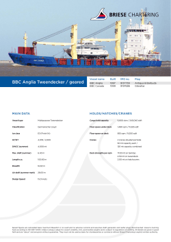


© Copyright 2026