
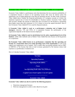
Part No. WR-PA5050UW3-S-M60 Emitted Color Ultra Super
MASTER INSTRUMENT CORPORATION WR-PA5050UW3-S-M60 Part No. Emitted WR-PA5050UW3-S-M60 Color Chip Materia Len's Color Ultra Super White InGaN Water Clear ◆ Features: Compatible with automatic placement equipment Compatible with reflow solder process This product doesn’t contain restriction Substance, comply ROHS standard. ◆ Applications: Indoor and outdoor displays Camera Flash or Backlighting ◆ Package Dimensions: Unit:mm Toleranc:±0.2mm unless otherwise noted Electrodes: Ag Plating Copper Alloy Encapsulating Resin: Silicon Resin Package: Heat-Resistant Polymer This PDF is a property of Master Instrument Corporation. Email: [email protected] Website: www.micindia.com MASTER INSTRUMENT CORPORATION WR-PA5050UW3-S-M60 ◆ Absolute Maximum Rating (Ta=25℃) Parameter Symbol Max. Unit Pulse Forward Current IFP 100 mA/chip DC Forward Current IF 30 mA/chip Reverse Voltage VR 5 V/chip Operating Temperature Range Topr -40℃~85℃ ℃ Storage Temperature Range Tstg -40℃~100℃ ℃ Tj +110 ℃ Tunction Temperature * IFP condition: pulse width ≤1ms ,duty cycle ≤1/10 ◆ Electrical Optical Characteristics(Ta=25℃) Parameter Symbol Min Typ. Max. Unit Test Condition Luminous Intensity IV 6400 -- 8000 mcd IF=20mA/chip Forward Voltage VF 2.9 -- 3.5 V IF=20mA/chip Tc 8000 -- 11000 K IF=20mA/chip IR -- -- 10 uA VR=5V/ chip Spectral Line Half Width Δλ -- 30 -- nm IF=20mA/chip Viewing Angle 2θ1/2 -- 120 -- Deg. IF=20mA/chip Color Temperature Reverse Current Notes: 1.Three chips of total currents are 60mA 2.Tolerance of Luminous Intensity ±10% 3.Tolerance of Peak Wavelength ±2nm 4. Tolerance of Forward voltage ±0.05V 5. Luminous Intensity is measured by MIC equipment on bare chips This PDF is a property of Master Instrument Corporation. Email: [email protected] Website: www.micindia.com MASTER INSTRUMENT CORPORATION WR-PA5050UW3-S-M60 ◆ BIN range Luminous intensity (tolerance is ±10% @ If =20mA/ chip ): BIN CODE Min.(mcd) Max. (mcd) B9-2 6400 6800 B9-3 6800 7200 B10-1 7200 7600 B10-2 7600 8000 Forward voltage (tolerance is ±0.05V @ If =20mA/ chip): BIN CODE Min.(V) Max. (V) -- 2.9 3.1 -- 3.1 3.3 -- 3.3 3.5 Bin range of Chromaticity Coordinates (tolerance is ±0.01 @ If =20mA/ chip): Bin Code X,Y XT YT XR YR XB YB XL YL BT 0.29 0.29 0.30 0.30 0.29 0.31 0.28 0.30 BU 0.30 0.28 0.31 0.29 0.30 0.30 0.29 0.29 BR 0.28 0.28 0.29 0.29 0.28 0.30 0.27 0.29 BS 0.29 0.27 0.30 0.28 0.29 0.29 0.28 0.28 Please refer to CIE 1931 Chromaticity diagram This PDF is a property of Master Instrument Corporation. Email: [email protected] Website: www.micindia.com MASTER INSTRUMENT CORPORATION WR-PA5050UW3-S-M60 Chromaticity Coordinates & Bin grading diagram:(IF=20mA /chip) 0.36 0.35 0.34 0.33 0.32 0.31 BT 0.30 BU BR 0.29 BS 0.28 0.27 0.26 0.36 0.35 0.34 0.33 0.32 0.31 0.30 0.29 0.28 0.27 0.26 0.25 0.9 0.8 0.7 0.6 cy 0.5 0.4 0.3 0.2 0.1 0 0.1 0.2 0.3 0.4 0.5 0.6 0.7 0.8 cx This PDF is a property of Master Instrument Corporation. Email: [email protected] Website: www.micindia.com MASTER INSTRUMENT CORPORATION WR-PA5050UW3-S-M60 ◆ Package Label:(For example) LED Type Part No. Parameter Classing Quantity and Sealing Date Lot No. ◆ Soldering Pad Dimensions: ◆ Soldering Conditions (Maximum allowable soldering conditions) • Reflow soldering profile <Pb-free solder> 260℃ Max. 10sec.Max. Temperature 3℃/sec. 210℃ Pre-heating 120~160℃ 3℃/sec. -4℃/sec. 60~120sec. . 120sec.Max. Time • Reflow soldering should not be done more than two times. • Do not stess its resin while soldering. • After soldering,do not warp the circuit board. • Pay attention to electrostatic(ESD). This PDF is a property of Master Instrument Corporation. Email: [email protected] Website: www.micindia.com MASTER INSTRUMENT CORPORATION WR-PA5050UW3-S-M60 φ13± 0.2 φ60 φ180 ◆ Package Tape Specifications: (500 or 1000 pcs/Reel) φ 1 .5 4 0.28 5.5 12.0 5.5 _ 1.75 13.0± 0.1 15.0± 0.15 + Polarity 8 2.05 5.5 Reel Lead Min.60mm No LEDs 4 Reels in one Box 16 Boxes in one Carton This PDF is a property of Master Instrument Corporation. Email: [email protected] Website: www.micindia.com MASTER INSTRUMENT CORPORATION WR-PA5050UW3-S-M60 ◆ Typical Electro-Optical Characteristics Curves: Forward Current Vs. Forward Voltage Ta=25℃ Ta=25℃ 100 100 Forward Current (mA) Relative Luminous Intensity (%) Relative Luminous Intensity Vs. Wavelength 75 50 25 0 400 440 480 520 560 600 640 680 720 50 30 20 10 0 1.5 760 200 Relative Luminosity(%) 50 40 30 20 10 3.0 3.5 4.0 175 150 125 100 75 50 25 0 0 0 20 40 60 80 0 100 200 10 20 30 40 50 Forward Current (mA) Ambient Temperature Ta (° C) Relative Luminosity (%) 2.5 Forward Current Vs Relative Luminosity Ta=25℃ Forward Current Vs Ambient Temperature Forward Current(mA) 2.0 Forward Voltage (V) Wavelength (nm) Relative Luminosity Vs Ambient Temperature If=20mA/ chip -20° -10° 0° 10° -30° 20° 30° 40° -40° 150 50° -50° 60° -60° 100 70° -70° 50 80° -80° -90° 0 0 20 40 60 80 100 Ambient Temperature Ta (° C) 1.0 0.5 0 0.5 Radiation Angle This PDF is a property of Master Instrument Corporation. Email: [email protected] Website: www.micindia.com 1.0 90° MASTER INSTRUMENT CORPORATION WR-PA5050UW3-S-M60 ◆ Reliability (1) Test Items and Conditions Sample Ac/ Re -40±5℃→25±5℃→100±5℃→25±5℃ (30min,5min,30min,5min) 100 Cycles 20 0/1 Ta:100±5℃ Test time=1000HRS(-24HRS,+72HRS) 20 0/1 Ta:85±5℃,RH:85±5%,IF=20mA/ chip Test time=500HRS(-24HRS,+72HRS) 20 0/1 Low Temperature Storage Ta:-40±5℃ Test time=1000HRS(-24HRS,+72HRS) 20 0/1 5 Operating Life Test Connect with a power IF=20mA/ chip Ta=Under room temperature Test time=1000HRS(-24HRS,+72HRS) 20 0/1 6 Thermal Shock -40±5℃→100±5℃ (15min,15min) 100 Cycles 20 0/1 20 0/1 NO Test Item 1 Temperature Cycle 2 High Temperature Storage 3 High Temperature And High Humidity Working 4 7 Test Conditions IR-Reflow Pb-Free Process ①80℃②100℃③120℃④160℃⑤170 ℃⑥235℃⑦270℃⑧255℃, 60cm/min,2 times (2)Criteria of judging the damage * Item Symbol Test condition Forward voltage VF Reverse current Criteria for judgement Min. Max. IF=Test Current / U.S.L*1.1 IR VR=5V / 15uA Luminous intensity IV IF=Test Current L.S.L*0.7 / Wave length λD/λP IF=Test Current / U.S.L±2nm Appearance / View check U.S.L: Upper standard level No mechanical damage L.S.L: Lower standard level This PDF is a property of Master Instrument Corporation. Email: [email protected] Website: www.micindia.com MASTER INSTRUMENT CORPORATION WR-PA5050UW3-S-M60 ◆ Storage and application notices 1. Storage 1. Calculated shelf life in sealed bag : 12 months at <30℃ and <90% relative humidity (RH) 2.1 TOP LED : After bag is opened, devices that will be subjected to reflow solder or other high temperature process must be: a) Mounted within: 168 hours of factory conditions ≤30℃/60% RH, or b) Stored at ambient of <20% RH 2.2 CHIP LED: After bag is opened, devices that will be subjected to reflow solder or other high temperature process must be: a) Mounted within: one year of factory conditions ≤30℃/60% RH, or b) Stored at ambient of <20% RH 3. Device require bake, before mounting, if: a) Humidity indicator Card reads >10% when read at 25±5℃ b) Above conditions are not met Baking condition: 24 hours at 60±3℃ and <5% RH 4.The internal and esterand boxes can not be contacted with ground to prevent absorption of moisture; 5.No acid, alkali, salt, corrosive and explosive gas; away from sunlight and keep the environment clean; 2. Application 1.Do not use any unknown chemical liquid to clean LED, it will damage the LED resin surface; use the alcohol under the room temperature if necessary but less than 1 min, or use the ultrasonic cleaning with proper characters, such as correct power, frequency ,etc; 2.Do not touch the epoxy resin area when carrying LEDs by tweezers (as the following pictures), especially after the soldering process, the epoxy resin will turn to soft, the internal instruction will be damaged by the tweezers which cause the electric character’s failure; nozzle is recommended by using SMT mounting. Correct Incorrect This PDF is a property of Master Instrument Corporation. Email: [email protected] Website: www.micindia.com MASTER INSTRUMENT CORPORATION WR-PA5050UW3-S-M60 3. Soldering iron: double-side soldering iron with power of less than 25W; soldering temperature: less than 300℃; soldering time: less than 3sec.; 1 time completed is recommended, if the 2nd soldering process is requested, 3mins must be left to ensure the high temperature status can return to room temperature; a. REFLOW soldering: set and test the temperature of the different area of REFLOW equipment in advance; b. To set the peak temperature according to different SMDs, but the actual peak temperature should be less than 260 ℃ ,processing time should be less than 10sec, only 1 time is allowed; 4.SMDs should be soldered at the coordinated position on the PCB ; 5.Note of Electrical matter: ① One-way conduction, LED does not allow the reverse driving; ② LED is a kind of constant current component which can not be lighted by the constant voltage mode; a smaller voltage fluctuation can cause the large current fluctuation which causes the failure of LED; Each LED should be drove under constant current mode if in a parallel circuit design, otherwise, the colour and brightness will be nonuniform; When the environmental temperature rising, the LED junction temperature will rise, internal resistance will decrease, so the current will be increased by the constant voltage power which short the life span; ③ If the brightness of lighting source can meet the requirement, we recommend using the driving current less than the rated current, in order to improve the product’s reliability; 6.LED is a kind of electrostatic sensitive devises, anti-static measures have to be processed during storage and operation: ① LED production workshop should lay anti-static floor and ground connection, the work table have to use the anti-static materials and cover a table mater with the surface resistance of 106-109Ω ② Production machine: REFLOW, SMT equipment, electric iron, test equipment; all the equipments must be well grounded, and the grounding alternating current impedance should be less than 1.0Ω. A fan need to be installed on the equipments and production processes that easy to generate static electricity; the operators must wear anti-static clothing, shoes, wristband, and gloves, etc. in the process; ③ LEDs must be contained in the anti-static box, and all the package material should be the anti-static materials; This PDF is a property of Master Instrument Corporation. Email: [email protected] Website: www.micindia.com MASTER INSTRUMENT CORPORATION WR-PA5050UW3-S-M60 7.The details electronic characters can refer to our product specification. ◆ Notes: 1、Above specification may be changed without notice. We will reserve authority on material change for above specification. 2、When using this product, please observe the absolute maximum ratings and the instructions for the specification sheets. We assume no responsibility for any damage resulting from use of the product which does not comply with the instructions included in the specification sheets. This PDF is a property of Master Instrument Corporation. Email: [email protected] Website: www.micindia.com


© Copyright 2026