
Surgical management of cervical myelopathy: indications and
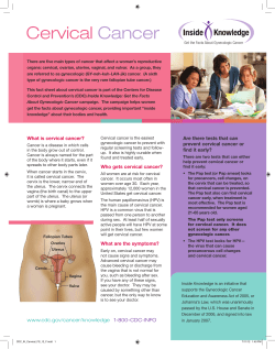
The Spine Journal 6 (2006) 242S–251S
Surgical management of cervical myelopathy: indications and
techniques for multilevel cervical discectomy
Virany H. Hillard, MD, Ronald I. Apfelbaum, MD*
Abstract
BACKGROUND CONTEXT: Surgery is usually required for treatment of cervical myelopathy
to decompress the neural elements, restore lordosis, and stabilize the spine. By addressing these
problems, the neurological deterioration may be halted.
PURPOSE: Multilevel cervical discectomy and fusion offers several advantages over other
approaches. The authors describe the technique, discuss the indications, and present the potential
complications associated with it.
METHODS: Decompression is achieved via discectomy and subsequent removal of the osteophytes using a curetting technique. Preparation of end plates in a parallel fashion allows for gapless
grafting of allograft bone for enhancement of fusion. A dynamic plate and screw system strengthens
the construct.
RESULTS: A high rate of fusion can be obtained using the technique of multilevel cervical
discectomy and fusion with acceptable levels of complications. It is especially useful in cases of
spondylosis that have a kyphotic deformity because, in addition to anterior decompression, it allows
reconstruction of the spine to help restore a lordotic curvature.
CONCLUSIONS: Multilevel cervical discectomy and fusion has proven to be very effective in
decompressing and stabilizing the spine for treatment of cervical myelopathy. Ó 2006 Elsevier
Inc. All rights reserved.
Keywords:
Multilevel cervical discectomy; Dynamic plating; Anterior fusion; Allograft
Introduction
Degenerative spondylosis leading to stenosis, rheumatoid arthritis, and trauma are some of the more common
causes of compression of the spinal cord that can result
in cervical myelopathy. The symptoms of cervical myelopathy are due to impaired motor and sensory functionality.
They include clumsiness of the hand, difficulty walking,
impaired balance and coordination, and sensory complaints
of numbness or tingling in the hands and feet [1]. Cervical
spondylosis, which most commonly occurs after age 50, is
the most common cause of cervical myelopathy. It evolves
from desiccation of the disc that leads to reduced disc
FDA device/drug status: approved for this indication (anterior cervical
plating [ABC Plate]).
Author RIA acknowledges a financial relationship (consultant for Aesculap Instrument Co., Center Valley, PA) that may indirectly relate to the
subject of this research.
* Corresponding author. Department of Neurosurgery, University of
Utah School of Medicine, 30 North 1900 East, Suite 3B409, Salt Lake
City, UT 84132. Tel.: (801) 581-6908; fax: 801-581-4138.
E-mail address: [email protected] (R.I. Apfelbaum)
1529-9430/06/$ – see front matter Ó 2006 Elsevier Inc. All rights reserved.
doi:10.1016/j.spinee.2006.05.005
height and bulging of the disc posteriorly into the spinal
canal. The bulging disc may then calcify and, along with
marginal osteophyte formation and uncovertebral spurring,
narrow the spinal canal. The resultant foraminal and spinal
canal stenosis produces radiculopathy and myelopathy,
respectively [2,3].
Surgery is usually required to decompress the neural
elements, restore lordosis, and stabilize the spine to prevent
additional degeneration at the affected level. Surgery for
cervical myelopathy has been performed by both posterior
(laminectomy, laminoplasty) and anterior (corpectomy,
multilevel discectomy) approaches, each with unique
advantages and disadvantages.
Although an element of surgeon preference will of necessity be involved, some principles can assist in the selection of the appropriate approach. The location of the
stenosis and the alignment of the cervical spine should be
evaluated when choosing between an anterior and a posterior procedure. If the compression is posterior and related
primarily to facet hypertrophy or buckling of the ligamentum flavum, posterior decompression should be considered
[4]. However, ligamentum infolding can also be corrected
V.H. Hillard and R.I. Apfelbaum / The Spine Journal 6 (2006) 242S–251S
indirectly by restoring disc space height anteriorly, so this
factor alone is not weighted heavily when deciding on an
approach. If the compression is from anterior osteophytes
or disc herniations, an anterior approach via either multilevel discectomy or corpectomy offers the opportunity to
decompress the spinal cord directly and should be
considered.
The alignment of the patient’s spine must also be considered. If the spine is lordotic, a posterior procedure can
achieve an indirect decompression and may be an excellent
alternative to anterior decompression. If the spine is kyphotic, however, a posterior approach may be contraindicated because the spinal cord cannot displace dorsally
from the anterior compressive structures. In such cases,
a ventral approach is indicated. A ventral approach not only
allows direct decompression, but the proper use of intraoperative distraction often can help restore alignment as
well. This can not usually be accomplished by a posterior
approach. If the patient’s spine is straight, either procedure
can be used [5].
Other considerations when selecting the approach are
the extent of the degenerative process (ie, the number of
levels involved) and the patient’s age and overall medical
condition. Anterior surgery is more prolonged, and patients
with multiple levels will be more likely to have dysphagia
and voice problems postoperatively. Therefore, for an older
or infirm patient, posterior surgery may be preferable if the
alignment is not kyphotic.
In this article, we will discuss the use of the multilevel
cervical discectomy for anterior decompression of cervical
myelopathy. We believe that this procedure has several advantages over single or multilevel corpectomies. Multilevel
cervical discectomy can achieve the goal of decompression
as well as corpectomy when proper technique is used to remove the posterior osteophytic protrusions encroaching on
the spinal canal and neural foramen. However, by sparing
the vertebral bodies, multiple points of fixation exist, allowing for distraction and restoration of lordosis, which is then
maintained by the interbody grafting technique [6]. The
spine is then stabilized with a dynamic anterior cervical
plate. In a multilevel cervical discectomy, the grafts are
shorter than if a corpectomy is done. This may increase
the rate of fusion and avoid late failures by decreasing
the distance across which fusion and ultimately bone replacement by creeping substitution must occur.
Indications
Multilevel cervical discectomy is appropriate for use in
cases in which the compressing pathology is located anterior to the spinal cord. This includes central, broad-based
disc herniations and large bridging osteophytes at or adjacent to the level of the disc space. An anterior approach offers the most direct access to the cause of the myelopathy in
these cases. It also provides access in cases of segmental
243S
ossification of the posterior longitudinal ligament (PLL)
in which the ligamental ossification is confined primarily
to the disc space region and is not contiguous or extending
extensively behind the vertebral body.
Multilevel cervical discectomy and fusion is especially
indicated for patients with cervical spondylosis who do
not have a lordotic spine. Posterior operations usually cannot restore lordosis and, if they do not, posterior decompression is not adequate to decompress a cord draped
over the residual anterior osteophyte. Addressing the problem from the front also allows the surgeon to distract and
restore disc height, which corrects the in-buckling of the
elastic ligamentum flavum. A multilevel discectomy and
fusion also provides multiple distraction points and therefore can restore lordosis more effectively than if a multilevel
corpectomy approach is used. Lordosis is better achieved
with interbody grafting, especially in comparison with
a long, straight corpectomy graft such as fibular bone.
The trade-off here is that removal of the osteophyte that extends behind the vertebral body is more difficult and timeconsuming when an interbody approach is used. However,
the same degree of decompression as is achieved with a
corpectomy can be reliably achieved using the techniques
described here.
Technique
Preparation and position of patient
If direct laryngoscopy for intubation cannot be easily accomplished in patients with cervical stenosis without hyperextension of the neck, which can worsen myelopathy,
indirect techniques, such as fiberoptic intubation, should
be used. A dose of antibiotics is given before the start of
the operation. The patient is positioned supine with the
head of the bed elevated to place the neck above the heart
level. This enhances venous drainage and reduces bleeding.
The table is flexed so the patient does not slide down
toward the foot of the table, and the legs are kept level to
avoid venous pooling. We place 10 pounds of halter
traction on the head and a rolled towel under the neck to
stabilize it. Both arms are encased in stockinette gauze
tubing, which is secured with tape starting at the shoulders
and wrapped in a loose spiral to below the hands. The
stockinette then continues to the end of the table where
5 pounds of weight is applied to each arm. This results in
steady gradual traction to allow for consistent fluoroscopic
visualization of the inferior end of the cervical spine.
The C-arm fluoroscope is positioned for lateral imaging
of the cervical spine and left in place during the whole procedure. To ensure a true lateral image, the C-arm should be
positioned so that the facets on each side are superimposed
in both cranial–caudal and anterior–posterior directions.
The surgeon stands alongside the patient at the level of
the torso just caudal to the fluoroscope with the surgical
244S
V.H. Hillard and R.I. Apfelbaum / The Spine Journal 6 (2006) 242S–251S
assistant on the opposite side. This arrangement allows for
instantaneous fluoroscopic images as needed throughout
any stage of the operation. The operating microscope base
is positioned on the cranial side of the fluoroscope and set
up with a side observer tube rather than opposing viewing
positions. Thus, both the surgeon and the assistant have access to the field at approximately a 45 angle to the sagittal
plane for both the macroscopic and the microscopic portions of the operation.
Surgical exposure of the anterior spine
The fluoroscope is used to identify the level for the surgical incision. We prefer our incision to be placed slightly
above the midpoint of the extent of surgical exposure, as it
is easier to expose inferiorly than superiorly. A skin crease
closest to the desired incision level is identified. A horizontal incision will allow access to multiple disc levels by
opening the sternocleidomastoid fascia widely. The retractor system is then repositioned as needed to access specific
levels. A vertical incision along the sternocleidomastoid
can be used in difficult necks, although this incision is
not as cosmetic.
The skin is prepared and draped in the usual manner. Local anesthetic with 1:200,000 epinephrine is used to infiltrate the skin. After the skin incision and dissection of
the subcutaneous fat, a Weitlaner retractor is used to retract
the skin incision, and the platysma is identified, elevated
with a curved clamp, and incised with electrocautery. The
sternocleidomastoid is identified, and the superficial cervical fascia along its medial border is sharply incised. Extending this opening of the fascia superiorly and
inferiorly as far as possible is the key to adequate multilevel
vertebral exposure. Blunt finger dissection is then performed in the natural tissue plane between the carotid
sheath laterally and the esophagus and trachea medially
down to the anterior spine. If the omohyoid muscle crosses
the field, it can usually be mobilized for exposure. Rarely, it
may need to be bisected. Handheld Cloward retractors are
positioned for exposure, and the prevertebral fascia is
opened in a cranial–caudal fashion in between the two longus colli muscles down to the level of the anterior longitudinal ligament (ALL).
The appropriate levels of the disc spaces are confirmed
with the fluoroscope. The midline can be identified by reference to the medial edge of the two longus colli muscles.
By marking the midline with monopolar cautery and reinforcing this with a marking pen (Fig. 1A) above and below
the extent of the ALL that will be incised and retracted, the
midline can be identified throughout the procedure. This
will help proper positioning of the plate later in the
procedure.
An incision in the midline is then made with the monopolar cautery through the ALL down to the vertebral body. A
small Key periosteal elevator is then used to elevate the
ALL and longus colli muscle subperiosteally (Fig. 1B)
from the middle of the vertebral bodies laterally to allow
for placement of the retractor system. The mobilization of
the longus colli muscle should extend over the majority
of the vertebral bodies above and below the disc levels to
be treated to allow for placement of the instrumentation.
The ligament, muscle, and periosteum are elevated together
widely over the entire anterior surface of the vertebral body.
Care should be taken to minimize shredding of the periosteum, especially if it is adherent to anterior osteophytes that
may be present.
A Caspar retractor system using sharp-toothed blades of
the shortest length possible is then inserted beneath the longus colli muscle on either side and opened to expose the
working field further (Fig. 1C). Sharp-toothed blades will
engage tightly into the preserved periosteum/longus colli/
ALL layer and are less likely than blunter blades to slip
and compress the trachea and esophagus medially and the
carotid arteries laterally. At this time, the endotracheal tube
Fig. 1. (A) Exposure of the anterior surface of the spine showing the midline marked in the anterior longitudinal ligament above and below the level of
fusion. (B) The periosteum/anterior longitudinal ligament/longus colli complex is elevated with a Key periosteal elevator. (C) Self-retaining retractors are
placed under the longus colli muscles, and the distractor is inserted over the distraction pins at the upper level in preparation for the decompression.
V.H. Hillard and R.I. Apfelbaum / The Spine Journal 6 (2006) 242S–251S
cuff is deflated and reinflated by the anesthesiologist to allow the endotracheal tube to recenter itself inside the larynx
after the trachea is retracted. This has been shown to reduce
the incidence of recurrent laryngeal nerve injury significantly [7].
Before the distraction pins are placed, the anterior osteophytes are removed using bone rongeurs or a high-speed
drill. Lateral fluoroscopy is helpful in determining the extent of osteophyte removal down to the anterior margin of
the vertebral body. The Caspar distraction posts are then
placed under fluoroscopic guidance, aiming perpendicular
to the posterior margin of the vertebral body and choosing
a length to engage as much of the vertebra as can safely be
achieved (Fig. 2, top). The cranial distraction pins are usually positioned at the upper third of the vertebral body to be
fused and the caudal pins are placed at the lower third of
the vertebral body, thereby avoiding any overlap in the permanent screw positions. Intervening pin placement is usually centered in the vertebra. The pins will often not be
parallel to one another because of the degeneration of the
spine. After the disc space is emptied, cervical lordosis will
Fig. 2. Diagram illustrating post placement. The posts are placed above
and below the midpoints of the respective vertebrae in this two-level procedure. All posts are placed perpendicular to the end plate and will not be
parallel until distraction is applied (bottom).
245S
be restored as distraction is applied (Fig. 2, bottom). The
use of these distraction pins is an important and powerful
tool whose value is often underestimated. Their use increases disc space height (and hence access) as well as restores lordosis. The distraction posts also help retract the
soft tissues at the extremes of the incision so we usually
do not need to use cranial–caudal retractors. For extensive
multilevel exposure, we usually place three posts and treat
two interspaces including grafting, then move to the other
interspaces, removing the initial posts and placing the
remaining ones as needed.
Removal of disc and preparation of end plates
We usually begin the discectomy at the highest disc level
to be addressed and proceed inferiorly. The distractor is
placed over the post above and below the disc level, and
distraction is applied. The disc annulus is incised in a rectangular fashion with a #15 blade, and a pituitary rongeur is
used to perform the initial discectomy. Angled curettes are
then used to evacuate the nucleus pulposus and remove the
cartilaginous end plates. As the discectomy progresses, additional distraction is applied to maximize the restoration of
lordosis and height of the disc space.
The end plates are then flattened so that the later grafting
can be done with a parallel-sided graft that will be in close
apposition over its entire surface to achieve a ‘‘gapless’’
graft position. This involves shaping the vertebral end
plates with a high-speed drill using magnified vision, preferably with the operating microscope, as it provides superior visualization and illumination. The microscope also
allows the assistant to have good magnified vision without
interfering with the surgeon’s view. In addition, a video image is obtained to allow the scrub nurse to see the surgery
and thereby assist more effectively.
The superior end plate of the disc space is usually cup
shaped. To flatten it, the anterior portion in front of the central depression is removed using repetitive side-to-side
stroking movements of the drill to create a flat surface from
one side of the vertebral body to the other (Fig. 3). Once the
anterior portion is flattened (Fig. 4C), we can often see residual cartilaginous end plate and we will remove it with
a curette. The microscope is then positioned so that the field
of view is coaxial with the end plate (Fig. 4H). This helps
create the desired flat surface as protruding irregularities
are easily seen and removed. The posterior part of the superior end plate of the disc space is then resected (Fig. 4D) as
needed to flatten it down to the PLL. Again, gentle side-toside sweeping movements of the drill are used.
We then turn our attention to the inferior surface of the
disc space. It generally slopes cranially at its depth and may
also have an upward curve at the lateral ends. Using the
flattened superior end plate as a visual reference, the inferior end plate is shaped to be parallel to the superior from
side to side, and then flattened to be anterior–posteriorly
parallel to the already flattened superior end plate. This
246S
V.H. Hillard and R.I. Apfelbaum / The Spine Journal 6 (2006) 242S–251S
Fig. 3. Radiographic imaging of interspace preparation. (A) Interspace has been distracted. (B) Anterior osteophyte removal begins at the anterior inferior
lip of the upper vertebral body using the drill. The lines indicate the resection planes to flatten the vertebral end plates. (C) The bone to be removed is highlighted. The bone within the interspace is removed with the drill, whereas the bone behind the vertebral body (arrow) is removed with curettage.
involves resecting increasing amounts of bone as the resection proceeds into the depth of the interspace (Fig. 4E).
Progress can be checked frequently with the fluoroscope,
which aids in achieving perfectly flattened parallel end
plates.
Decompression of the spinal canal and foramen
As the end plate recontouring is completed to the level
of the PLL, a substantial portion of the osteophytic protrusion into the spinal canal will have been removed. The PLL
provides protection for the neural elements as this is being
done. Light pressure with the drill will progressively thin
down and remove the bone to the PLL. The end plates
can then be undercut 1–2 mm with the drill to start to
remove residual osteophytes behind the margins of the
vertebrae (Fig. 4F).
It is important that the vertebral bone removal be done to
almost the full width of the interspace to resect the enlarged
uncinate processes and uncinate spurs bilaterally. At the lateral margins of the interspace posteriorly, we use the drill to
complete the removal of the disc and open the neural foramina laterally, in essence beginning an anterior foraminotomy, which will then be completed with curettage. We
avoid downward pressure of the drill in this region to avoid
additional pressure on the root that is exiting in an anterior
oblique angulation through the foramen.
We then complete the removal of the osteophytes and
complete the spinal canal decompression with curettage using a series of angled curettes. Initially, a 5-0 angled curette
is used to separate the PLL from the vertebrae and begin the
bone removal. A standard 9-inch curette is adequate for this
but does not allow enough force to be applied to remove
dense osteophytes. We then switch to a 4-0, 45 up-angled,
longer curette (12’’ handle) to work on the superior vertebra
and also the foramen bilaterally. To complete the removal
of the superior osteophytes (Fig. 4I) and for all of the inferior vertebral osteophyte removal (Fig. 4J), we use 12-inch
4-0 curettes with 90 angulation to minimize intrusion into
the spinal canal. These curettes are available with three different ‘‘reaches’’dthat is, increasing length from the shaft
to the cup of the curette. These are used in sequence behind
the inferior and superior vertebrae.
The technique of curettage is not immediately intuitive
but is easily learned. Initially, the instrument is placed behind the vertebra very delicately. One feels with it as
though one were using a microdissector and in this manner
gains useful information about the anatomy of the osteophytes. It should never be forced. If it cannot be fit in to
its full reach, partial cuts at less than full depth are initially
used and then the instrument is advanced. The cutting action of the curette is achieved with a rotatory motion about
the shaft of the instrument, not by a side-to-side translation.
The cutting occurs between the tool and hard underlying
bone and so requires that the tool be held very firmly
against the bone. The technique therefore is to insert the
tip gently, and then pull the tip very firmly up against the
vertebral body while rotating the instrument (Fig. 5). The
upward pull is relaxed just as the tip emerges from behind
the body. We usually start in the middle and move to each
side by reinserting the curette at or just behind where it
emerges from the previous cut. At the ends of the
V.H. Hillard and R.I. Apfelbaum / The Spine Journal 6 (2006) 242S–251S
247S
most vertebrae. Additional osteophytes beyond that distance are approached from the adjacent interspace.
As we work and once sufficient decompression has been
achieved, hemostasis is obtained using Gelfoam slurry
(Gelfoam powder mixed with thrombin), which is placed
in the disc space and tamponaded into the epidural space
with a cottonoid patty. This is repeated as needed. This will
usually stop bone bleeding as well, but any residual bony
bleeding from the posterior vertebral body can be stopped
using wax applied to the site with an angled Caspar periosteal elevator. Any excess wax is then removed. We try to
avoid use of wax on the interbody surfaces because it
may hinder fusion. Epidural veins and bleeding from the
PLL can also be cauterized using an angled bipolar tip at
a low power setting.
Graft selection and insertion
Fig. 4. Sequential steps in the multilevel discectomy and fusion procedure
are diagrammed. (A) Initial view. (B) Anterior osteophyte removal. (C and
D) Flattening of superior end plate of upper vertebra to the depth of the
central depression. (E) Contouring of inferior end plate to parallel superior
vertebra. (F) Undercutting of marginal osteophyte. (G) Assessing end
plates for parallelism with caliper and measuring dimensions for grafting.
(H) View is obtained coaxial with the vertebra (*) rather than obliquely (#)
to perfect end plate flattening. (I and J) Curetting residual osteophytes behind the vertebra. (K) Graft placement.
interspace, the rotation is toward the midline to protect the
roots. Sequentially longer-reach curettes are used as dictated by the extent of the osteophytes. The longest curettes
will reach to just beyond the middle (vertebral height) of
Many types of grafting material have been used in the
interspace. Because the goal of grafting is to achieve a solid
fusion to provide structural support, bone (allograft or autograft) is the ideal material. It becomes living bone that
matches the strength and elasticity of the adjacent bone, responds to stress by becoming stronger, and is self-repairing
[8]. Synthetic materials lack all of these properties. They
may be a poor biomechanical match with the adjacent bone
and, if too dense, may erode into the vertebral bodies. They
may also stress-shield the adjacent graft and cannot repair
themselves if damaged. Cages and similar devices occupy
space that could, and in our opinion should, be occupied
by bone. The authors prefer to use allografting, and in particular, tricortical iliac crest bone, because it is an excellent
biomechanical match that provides a cortical shell for support and a cancellous core for early incorporation. It also
avoids donor site problems and pain. Tricortical iliac crest
allograft, when used in a two-level anterior cervical fusion
without plating, had a significantly lower fusion rate of
37% as compared with 83% for autograft [9], and is more
likely to collapse [10]. However, when used with anterior
cervical plating, allograft results in a fusion rate equal to
that of autograft [11] and superior to noninstrumented autograft fusions [12]. It is important, however, to use allograft
bone that has not been subjected to high-dose radiation (O3
megarads), as this substantially weakens the graft [8]. Regardless of the material chosen, the graft should ideally fill
most of the prepared interspace, which in the middle to
lower cervical spine will typically be 18–22 mm wide
and 14–18 mm deep.
The Caspar adjustable calipers are used to measure the
height, width, and depth of the prepared disc space to determine the size of the graft. An allograft of the desired width
is then precisely cut to the correct height to fit snugly into
the distracted interspace using a parallel-bladed reciprocating saw. The graft depth is trimmed to a length approximately 1 to 2 mm short of the measured depth of the
interspace.
248S
V.H. Hillard and R.I. Apfelbaum / The Spine Journal 6 (2006) 242S–251S
Fig. 5. Curetting technique to remove the posterior osteophytes. The left
hand pulls firmly upward to keep the curette against the bone as the right
hand rotates the instrument to cut the bone away.
Once fashioned, the tricortical graft is inserted with the
cortical surface toward the anterior margin of the vertebral
body and the noncorticated surface toward the dura mater
and gently tapped into position. We pass a nerve hook bilaterally and palpate the back of the graft, checking with fluoroscopy to verify that it has not rotated and sits in good
position. The distraction is then released. This process is repeated at each level. If the fusion involves more than two
levels, we first complete the decompression and grafting
of the upper levels and then remove the distraction pins
at these levels and relocate the retractor to expose the lower
levels. Once the decompression is completed at these
levels, we complete our fusion with bone grafting placed
first in the lowest disc space to allow a more generous graft
at that level, which is exposed to the most stress. We then
proceed with inserting the remaining bone grafts in a caudal
to cranial direction.
Plating and screw placement
Many cervical plating systems are currently available.
We prefer a dynamic plating system that does not restrict
settling. Dynamic plating systems allow for true load
sharing on the bone graft, because the forces working on
the bone graft include the axial load from the weight of
the head and the cervical muscle forces [13,14]. Over time,
these forces are maintained even when the grafts are partially absorbed as part of the normal bone-healing process.
This axial loading seems to encourages faster and more
complete bone incorporation and therefore a higher rate
of fusion [15].
Placement of the ABC (Aesculap, Tuttlingen, Germany)
dynamic plating system is described below. Before the start
of plating, the distraction pins are removed and the pin
holes are waxed for hemostasis. The shortest plate possible
is preferred. We choose a plate that covers no more than
half of the upper and lower vertebral bodies to be fused.
As settling occurs in the first month or two, this shorter
plate will extend over a greater extent of these vertebral
bodies but will be less likely to encroach over the adjoining
disc spaces. The plate length and alignment are verified
with fluoroscopy. Any residual anterior osteophytes are removed to allow the plate to sit flat on the anterior surface of
the vertebrae. Any additional contouring of the plate that is
needed is performed using the system’s benders to ensure
that the plate lies flush against the anterior spine surface.
The plate is then aligned using the previously placed midline markings, and temporary pins are placed at both ends
to hold the plate in position.
The two most cranial screws are aimed upward and inward to increase holding strength and the most caudal
screws are aimed downward and inward. A double-barreled
drill guide, which creates convergent trajectories for the
screws, is used. The holes can be drilled or made with
a starter awl, but in either case, it is best to use fluoroscopic
control to optimize the position and angulation with the
vertebrae. When unicortical screws are used, the drill or
awl hole is usually placed to a 14-mm depth using the
fixed-depth drill guide. The fluoroscopic image of the drill
depth in the bone allows one to choose the best screw
length, which typically ranges from 14 mm to 18 mm but
can vary. Ideally, we prefer to use a screw length that traverses approximately 75% to 80% of the vertebral body
depth. These screws are self-tapping. When bone density
is poor, bicortical screws are preferable for their greater
pullout force; these are drilled with the adjustable-depth
drill guide, which allows the depth to be increased in 0.5mm increments. This allows the drilling to progress safely
under fluoroscopic control until the posterior cortex is attained. The bicortical screws are blunt tipped and not
self-tapping, so the pilot hole is also tapped under fluoroscopic control before they are placed. Rescue screws with
a larger diameter are also available if the initial screw torque is suboptimal.
After all screws are in position, the locking mechanism
of each screw is engaged to prevent back-out of the body or
plate, while allowing axial settling to occur. The most recent version of this system uses self-locking screws. In
the previous version, a locking tool engages the internal
V.H. Hillard and R.I. Apfelbaum / The Spine Journal 6 (2006) 242S–251S
locking pin and pulls the pin up into the locked position.
The temporary plating pins are then removed, and the holes
are waxed for hemostasis as needed.
Closure
Before closure, the wound is irrigated copiously with antibiotic solution to clean out any debris, blood, or devitalized tissue fragments. The retractor system is removed
one blade at a time. The longus colli is repositioned over
the lateral edge of the plate. Using the handheld Cloward
retractor, each layer of tissue is inspected for bleeding or
damage before closing with sutures. Once hemostasis is
achieved, we close in several layers and usually do not
use drains. The sternocleidomastoid muscle fascia is
brought together with 2-0 Vicryl absorbable sutures
(Ethicon, Inc., Somerville, NJ), and the platysma is reapproximated with 3-0 Vicryl sutures. The skin is closed with
4-0 Monocryl absorbable sutures (Ethicon, Inc.) using a
subcuticular stitch and reinforced with benzoin and SteriStrips (3M, St. Paul, MN).
Complications
Complications occurring with multilevel cervical discectomy approaches can be related to injuries to the soft tissue
during dissection or to the neurological elements. In addition, postoperative fusion or hardware failure can occur.
Among injuries related to dissection and mobilization of
soft tissue in the neck, recurrent laryngeal nerve injury
and swallowing difficulties are the most common postoperative problems. The reported incidences vary widely from
0.07% to 11% [16,17] to as high as 24.2% [20]. Baron
et al. [19] calculated the overall incidence reported in the
literature as 12.3% for dysphagia, 4.9% for hoarseness,
and 1.4% for unilateral true vocal fold motion impairment.
Most laryngeal nerve injuries are transient, lasting weeks or
months, and are now recognized as most commonly attributable to compression of the recurrent laryngeal nerve
within the endolarynx rather than to injury within the soft
tissue of the neck. The maneuver of deflating and reinflating the endotracheal cuff can significantly lessen the incidence of this complication. The temporary occurrence
rate fell from 6.8% to 1.7% when the maneuver was applied.
The permanent vocal cord paralysis rate was 0.3% [7].
The incidence of dysphagia can be as high as 50–67%
[18,19] after an anterior cervical procedure. Edwards et al.
[22] emphasized that it is frequently underreported. It is usually transient, however, with residual symptoms decreasing
to 4.8% after 6 months [23] and 23% at 10 months [23]. Although it appears to occur more frequently in anterior approaches, dysphagia may not be specific to them as it also
is reported in 20% of patients who had posterior operations
[23]. Instrumentation has not been shown to increase the risk
of dysphagia [23–25]. It has been noted that older patients
249S
have a higher risk of developing dysphagia [21,24] and that,
when tested, many of these older patients have preexisting
but subclinical swallowing dysfunction preoperatively [17].
This problem appears to be related to esophageal motility dysfunction secondary to or exacerbated by retraction.
Intermittently releasing the retractors to decrease soft-tissue
compression has been suggested to try to reduce this problem. Most people experiencing this complication will complain that solid or dry food gets stuck in the process of
swallowing. In these cases, diet modification until full recovery is recommended and, if dysphagia is very severe,
a temporary feeding tube may be used to supply adequate
nutrition. Perforations of the esophagus and trachea are
very rare injuries that may be avoided by proper placement
of the retractor blades underneath the periosteum/ALL/longus colli.
Other complications relating to anterior cervical surgery
include injuries to the vertebral artery and dural tears. Vertebral artery injury is rare and usually is related to an ectatic
nature of the vessel. It is more common in corpectomy than
in a discectomy [26]. Dural tears are also rare, but in cases
of ossification of the PLL, the ossification may involve the
dura mater, which may need to be resected. In such cases,
primary closure is not usually possible so the defect is covered with fascia lata or other suitable dural substitute. We
seal this with fibrin glue and place several layers over the
dural defect. A lumbar drain is then placed to divert the cerebral spinal fluid and reduce pressure on the surgical site
for approximately 3 days.
Neurological complications relating to surgery have
been reported to occur in 0.3% of patients [27] who have
had anterior cervical surgery and up to 5.5% in another series that included posterior operations for cervical myelopathy, which is known to have a higher neurological
complication rate than anterior operations [28–30].
Spinal nerve root deficits are more common than cord
injury. Many authors [18,31–33] have reported postoperative C5 radiculopathy, which may be immediate or delayed.
The cause of this is unknown. It has been hypothesized to
be possibly related to graft complications or to a tethering
effect on the nerve root when the spinal cord shifts as it is
decompressed. It occurs in both anterior and posterior approaches, with a higher incidence in posterior surgical techniques. Direct nerve root injury is rare but also can occur if
orientation is lost or drilling is not done with proper
technique.
Complications relating to bone grafting and plating include nonunion, and late failure such as graft collapse, fracture, or extrusion. Loss of alignment, plate breakage, and
screw breakage or backout may also occur. The introduction
of plating has increased the rate of fusion in multilevel
discectomy and arthrodesis [34–37]. Emery et al. [38]
reported a 6.9% rate of pseudoarthrosis in 108 patients
treated with anterior cervical discectomy and fusion for
cervical spondylotic myelopathy. Earlier rigid plating systems used in multilevel corpectomies have been reported
250S
V.H. Hillard and R.I. Apfelbaum / The Spine Journal 6 (2006) 242S–251S
Fig. 6. Images obtained for a 40-year-old myelopathic man who had transient quadriparesis after blow to head. (A) Lateral radiograph of spine with spondylotic changes. (B) T2-weighted magnetic resonance imaging showing multilevel disc degeneration and canal compromise. (C) Axial T2-weighted magnetic
resonance images at C4–5, C5–C6, and behind C6 body. (D) Postoperative radiograph showing decompression and grafting after restoration of lordosis. The
spine was then stabilized with an ABC dynamic plate from C4–C7.
to have a construct failure rate of 10–16%, whereas the
ABC dynamic plating system had no hardware failures
[39]. Screw or plate breakage does not occur because the
screws and plate are not under load in this dynamic system.
In addition, dynamic plating that allows for subsidence has
decreased the nonunion rate. In the senior author’s initial
reported experience, 93% fusion was achieved at 12 months
and the fusion rate reached 100% at 24 months using very
stringent criteria [40]. Graft extrusions, which have been
reported in noninstrumented fusion, are also eliminated
by plating [41].
Bracing
We do not routinely use postoperative bracing when this
approach is used and especially when dynamic plating systems are used. With dynamic (load-sharing) plating, compression is maintained on the graft, which, in addition to
its other aforementioned benefits, results in a stronger initial construct [14]. The authors prefer that the patients
use their neck muscles to regain neck mobility and strength,
which can best be achieved when no bracing is used. Infrequently, however, if the bone quality is of serious concern,
a rigid external collar for 6–8 weeks may be used. This is in
contradistinction to the practice of many surgeons [42];
however, we have seen no adverse affects and believe it improves the patients’ sense of well-being and facilitates their
recovery.
Conclusion
Multilevel cervical discectomy and fusion is an appropriate technique for treatment of cervical myelopathy. It
allows restoration of the spinal canal and neural foramen
to normal dimensions to decompress the spinal cord and
nerve roots. It is especially useful in cases of spondylosis
that have a kyphotic deformity because, in addition to anterior decompression, it allows reconstruction of the spine to
help restore a lordotic curvature (Fig. 6). Lordosis is easier
to achieve and maintain because of the multiple points of
distraction and fixation in addition to the graft and interbody space shaping. Fusion rate may also be improved with
the shorter grafts, so that late failures can be avoided. In addition, an external orthosis is usually not necessary.
This approach is more labor-intensive and time-consuming than other approaches but has proven to be very effective in decompressing and stabilizing the spine. For all of
these reasons, multiple cervical discectomy for treatment
of cervical spondylotic myelopathy has become our technique of choice.
Acknowledgments
We thank Kristin Kraus for her excellent editorial assistance in preparing this paper.
References
[1] Edwards CC 2nd, Riew KD, Anderson PA, Hilibrand AS,
Vaccaro AF. Cervical myelopathy: current diagnostic and treatment
strategies. Spine J 2003;3:68–81.
[2] Small JM, Dillin WH, Watkins RG. Clinical syndromes in cervical
myelopathy. In: Herkowitz HN, Garfin SR, Balderson RA, et al.,
editors. The spine. Philadelphia: W.B. Saunders, 1999:465–74.
[3] Emery SE. Cervical spondylotic myelopathy: diagnosis and treatment. J Am Acad Orthop Surg 2001;9:376–88.
V.H. Hillard and R.I. Apfelbaum / The Spine Journal 6 (2006) 242S–251S
[4] Epstein JA, Epstein NE. The surgical management of cervical spinal
stenosis, spondylosis, and myeloradiculopathy by means of the posterior approach. In: Sherk HH, Dunn EJ, Eismont FJ, et al., editors.
The cervical spine, 2nd ed. Philadelphia: J.B. Lippincott, 1989:
625–43.
[5] McCormick WE, Steinmetz MP, Benzel EC. Cervical spondylotic
myelopathy: make the difficult diagnosis, then refer for surgery.
Cleve Clin J Med 2003;70:899–904.
[6] House PA, Apfelbaum RI. Anterior decompression for myelopathy:
multilevel discectomy. In: Herkowitz HN, editor. The cervical spine
atlas, 2nd ed. Philadelphia: Lippincott Williams & Williams, 2004:
167–83.
[7] Apfelbaum RI, Kriskovich MD, Haller JR. On the incidence, cause,
and prevention of recurrent laryngeal nerve palsies during anterior
cervical spine surgery. Spine 2000;25:2906–12.
[8] Steinmetz MP, Benzel EC, Apfelbaum RI. Subsidence and dynamic
cervical spine stabilization. In: Benzel EC, editor. Spine surgery:
techniques, complications avoidance, and management, 2nd ed.
Philadelphia: Elsevier Churchill Livingstone, 2005:1477–85.
[9] Zdeblick TA, Ducker TB. The use of freeze-dried allograft bone for
anterior cervical fusions. Spine 1991;16:726–9.
[10] Bishop RC, Moore KA, Hadley MN. Anterior cervical interbody fusion using autogeneic and allogeneic bone graft substrate: a prospective comparative analysis. J Neurosurg 1996;85:206–10.
[11] Tippets RH, Apfelbaum RI. Anterior cervical fusion with the Caspar
instrumentation system. Neurosurgery 1988;22:1008–13.
[12] Cauthen JC, Kinard RE, Vogler JB, Jackson DE, DePaz OB,
Hunter OL, et al. Outcome analysis of noninstrumented anterior cervical discectomy and interbody fusion in 348 patients. Spine
1998;23:188–92.
[13] Apfelbaum RI, Dailey AT, Barbera J. Clinical experiences with a new
load-sharing anterior cervical plate [abstr 64:144–145]. Paper presented at: Cervical Spine Research Society 27th Annual Meeting;
December 16–18, 1999; Seattle, WA.
[14] Brodke DS, Gollogly S, Alexander Mohr R, Nguyen BK, Dailey AT,
Bachus KN. Dynamic cervical plates: biomechanical evaluation of
load sharing and stiffness. Spine 2001;26:1324–9.
[15] Balabhadra RS, Kim DH, Zhang HY. Anterior cervical fusion using
dense cancellous allografts and dynamic plating. Neurosurgery
2004;54:1405–11; discussion 11–2.
[16] Frempong-Boadu A, Houten JK, Osbom B, Opulencia J, Kells L,
Guida DD, et al. Swallowing and speech dysfunction in patients undergoing anterior cervical discectomy and fusion: a prospective, objective preoperative and postoperative assessment. J Spinal Disord
Tech 2002;15:362–8.
[17] Yue WM, Brodner W, Highland TR. Persistent swallowing and voice
problems after anterior cervical discectomy and fusion with allograft
and plating: a 5- to 11-year follow-up study. Eur Spine J 2005;14:
677–82.
[18] Flynn TB. Neurologic complications of anterior cervical interbody
fusion. Spine 1982;7:536–9.
[19] Netterville JL, Koriwchak MJ, Winkle M, Courey MS, Ossoff RH.
Vocal fold paralysis following the anterior approach to the cervical
spine. Ann Otol Rhinol Laryngol 1996;105:85–91.
[20] Jung A, Schramm J, Lehnerdt K, Herberhold C. Recurrent laryngeal
nerve palsy during anterior cervical spine surgery: a prospective
study. J Neurosurg Spine 2005;2:123–7.
[21] Baron EM, Soliman AM, Gaughan JP, Simpson L, Young WF. Dysphagia, hoarseness, and unilateral true vocal fold motion impairment
following anterior cervical diskectomy and fusion. Ann Otol Rhinol
Laryngol 2003;112:921–6.
[22] Edwards CC 2nd, Karpitskaya Y, Cha C, et al. Accurate identification
of adverse outcomes after cervical spine surgery. J Bone Joint Surg
Am 2004;86-A:251–6.
251S
[23] Bazaz R, Lee MJ, Yoo JU. Incidence of dysphagia after anterior
cervical spine surgery: a prospective study. Spine 2002;27:2453–8.
[24] Smith-Hammond CA, New KC, Pietrobon R, Curtis DJ,
Scharver CH, Turner DA. Prospective analysis of incidence and risk
factors of dysphagia in spine surgery patients: comparison of anterior
cervical, posterior cervical, and lumbar procedures. Spine 2004;29:
1441–6.
[25] Mayr MT, Subach BR, Comey CH, Rodts GE, Haid RW Jr. Cervical
spinal stenosis: outcome after anterior corpectomy, allograft reconstruction, and instrumentation. J Neurosurg 2002;96:10–6.
[26] Curylo LJ, Mason HC, Bohlman HH, Yoo JU. Tortuous course of the
vertebral artery and anterior cervical decompression: a cadaveric and
clinical case study. Spine 2000;25:2860–4.
[27] Kraus DR, Stauffer ES. Spinal cord injury as a complication of elective anterior cervical fusion. Clin Orthop Relat Res 1975;112:130–41.
[28] Yonenobu K, Hosono N, Iwasaki M, Asano M, Ono K. Neurologic
complications of surgery for cervical compression myelopathy. Spine
1991;16:1277–82.
[29] Abumi K, Shono Y, Ito M, Taneichi H, Kotani Y, Kaneda K.
Complications of pedicle screw fixation in reconstructive surgery of
the cervical spine. Spine 2000;25:962–9.
[30] Blacklock JB. Fracture of a sublaminar stainless steel cable in the upper cervical spine with neurological injury: case report. J Neurosurg
1994;81:932–3.
[31] O’Toole JE, Olson TJ, Kaiser MG. Surgical management of dissociated motor loss following complex cervical spine reconstruction.
Spine 2004;29:E56–60.
[32] Keegan JJ. The cause of dissociated motor loss in the upper extremity
with cervical spondylosis. J Neurosurg 1965;23:528–36.
[33] Greiner-Perth R, Elsaghir H, Bohm H, El-Meshtawy M. The incidence of C5–C6 radiculopathy as a complication of extensive cervical decompression: own results and review of literature. Neurosurg
Rev 2005;28:137–42.
[34] Bolesta MJ, Rechtine GR 2nd, Chrin AM. Three- and four-level anterior cervical discectomy and fusion with plate fixation: a prospective
study. Spine 2000;25:2040–4; discussion 45–6.
[35] Bose B. Anterior cervical instrumentation enhances fusion rates in
multilevel reconstruction in smokers. J Spinal Disord 2001;14:
3–9.
[36] Caspar W, Geisler FH, Pitzen T, Johnson TA. Anterior cervical plate
stabilization in one- and two-level degenerative disease: overtreatment or benefit? J Spinal Disord 1998;11:1–11.
[37] Wang JC, McDonough PW, Endow KK, Delamarter RB. Increased
fusion rates with cervical plating for two-level anterior cervical
discectomy and fusion. Spine 2000;25:41–5.
[38] Emery SE, Bohlman HH, Bolesta MJ, Jones PK. Anterior cervical
decompression and arthrodesis for the treatment of cervical spondylotic myelopathy: two to seventeen-year follow-up. J Bone Joint Surg
Am 1998;80:941–51.
[39] Epstein N. Anterior approaches to cervical spondylosis and ossification of the posterior longitudinal ligament: review of operative technique and assessment of 65 multilevel circumferential procedures.
Surg Neurol 2001;55:313–24.
[40] Apfelbaum RI, Dailey AT, Soleau S, Barbera J. Clinical experience
with a new load-sharing anterior cervical plate. In: Watanabe K,
editor. Developments in neuroscience: Proceedings of the 2nd
International Mt. BANDAI symposium for neuroscience. Spine
Section. Philadelphia: Elsevier, 2002:563–80.
[41] Paramore CG, Dickman CA, Sonntag VK. Radiographic and clinical
follow-up review of Caspar plates in 49 patients. J Neurosurg
1996;84:957–61.
[42] Pickett GE, Van Soelen J, Duggal N. Controversies in cervical discectomy and fusion: practice patterns among Canadian surgeons. Can J
Neurol Sci 2004;31:478–83.


© Copyright 2026