
A method of extraction (restitution) of the energy supply
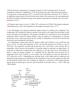
A method of extraction (restitution) of the
energy supply stored in liquid or gaseous
mediums and transformation of the energy
obtained into mechanical work
In 1607 Cornelius van Drebbel, a Dutch scientist, demonstrated a “continuously operating” clock to
the English kingjames I. The clock was set inmotion by a similar “continuously operating” motor,
or, to put it simply, a“perpetuum mobile”. Van Drebbel had already patented the clock in 1598.
However, unlike other numerous devices bearing the same name, the motor invented by Cornelius
van Drebbel really was a “continuously operat-ing“ one in some sense.
What was the secret of this clock (or,rather, of the motor that was settingit in motion)?
Van Drebbel’s contin-uously operating clock worked dueto the drive, which used, like any other real
motor, the single possible source of work - the non-equilibriurn (potential difference) of the
environment.
Van Drebbel made use of a specialtype of non-equilibrium, though itwas also related to pressure and
temperature differences. It may act in anideally balanced environment, the temperature and pressure
of which are everywhere equal. What is the secret of this effect and where does work come from?
The secret lies in the fact that potential differences do exist, manifesting themselves not spatially
but temporally (Editor: In Goran´s (Goran is our chief-engineer), given in1996 at the conference
“New Ideas in the Natural Sciences”, he proposed a similar principle for obtaining energy from a
single—wire power trans-mission line. Instead of a common potential difference U=X1—X2,
He proposed a chronal potential difference U=X(t1)-X(t2). This means thata potential difference
may be obtaine at a single point if a change in potential values is created). The principle can be
illustrated by the example of the atmosphere. Let us assume that no considerable pressure and
temperature differences are observed in the area where a motor is situated. But the pressure and
temperature (common in all points) still continue to change (both day and night). These differences
may be used for obtaining work (in full accordance with the laws of thermodynamics).
In a description of the invention titled “A method of extraction (restitution) of theenergy supply
stored in liquidor gaseous mediums and transforming the energy obtained into mechanical work"
(Patent claimed in Germany we are in the prozess) a version of a pseudo-continuously operating
working solar engine was proposed by him. In order to increase the power and the number of
cycles, the properties of two mutually unbalanced mediums — gas and
water — are most fully used.
Archimedes’ principle is considered as a corollary of the law of conservation of energy, in which the
buoyancy force is tied in with the energy consumed to create water and a.ir. The amount of this
energy determined such physical properties as density, thermal capacity and thermal conductivity.
The correlation of energy used for creating densities is partially reflected in the non-equilibrium
coefficient, equaling 820. If we found a way to fully use this non-equilibrium, we would obtain an
820-fold gain in energy. Non-equilibrium states are observed starting from the moment of feeding
air under a column of water. They accumulate when the air rises because the air volume increases, taking away heat from the water. Air is fed under the water column at a temperature less than
the temperature of the water, since if during the process of reaching atmospheric pressure the air
pressure equals 4 Atm (0.4 MPa) and the temperature is +20°C (293 K). the air will cool down to
75°C (198 K), i.e. by 95°C. Heat extraction will take place in conditions close to adiabatic. This
means that heat losses will be minimal due to the fact that water is a good heat accumulator but a
bad heat conductor.
Calculation of an energyextracting pneumohydraulic
turbine
A compressor is used as a source of compressed air. Dynamic and positive displacement-type compressors are the most suitable for this case. Since a dynamic compressor consumes more energy
thana piston-type one, we choose the latter:
Source of compressed air — VP2-10/9 piston-type compressor.
Compressor output — 0,167 m3/sec
Output pressure, MPa — 0.9 (9 Atm).
Compressors shaft capacity— 56.5 kW
Water cooling
The efficiency of a pneumohydraulic turbine will be evaluated by comparing the power supplied
and the power obtained, i.e. the amount of work per second.
A compressor’s output is evaluated by the volumeof air fed into it at atmospheric pressure. This
means that a productivity of 0.167 m3/sec is the air volume before entering the compressor and
after it rises in the turbine. While feeding air under the bottom level of the turbine, 0.167 m3/sec
of water will be displaced through the upper level. The same amount of water will be fed again
under the turbine‘s bottom level, thus creating an air-and-water mixture and causing it to move inside the turbine. The value of 0.167 ma/sec corresponds to the water consumption taken into consideration during the calculation of the capacity of a pneumohydraulic turbine. The capacity is calculated using the formula used for calculating the capacity of a hydraulic turbine:
N=9.81 x Q x H x n. where 9.81 m/sec2 — the gravitational acceleration;
Q — the water consumption in m3/s;
H ~ the head in (m);
h—Efliciency factor (which reaches rather high values and amounts to 0.94-0.95 or 94-95% under
most favorable conditions).
As an air-and-water mixture isused as the working medium, there is a necessity to justify the
use of this formula for calculating the capacity of a hydraulicturbine. We believe that the
most effective results can be obtained in the operation mode of the turbine when a mixture of
a 0.5 t/m3 density is used (comprising 50% water and 50% air).
In this mode, the air pressure is a little higher than the absolute pressure inside the turbine case.
Air is fed from the pressure tube of the compressor in the form of separate bubbles, which come
out from it in equal intervals. The total volume of bubbles equals the volume of water between them
in the turbine case. A bubble takes the shape of a spherical segment and works as a piston in a
limited space, displacing water in an upward direction only, since its backflow is impossible due to
the higher pressure, while its side-flow is impossible due to the incompressibility of water.
If a constant volume of air of 0.167 ma/sec is fed,0.167 ma/sec of water will be displaced. This
means that 2 >< 0,167 ma/sec of the air-and-water mixture will be displaced through the upper level
of the turbine, the stream velocity inside the turbine beinghigh.
Thus, we get:
N = 9.81 x 2 x Q x 0.5 x H x 3 = 9.81-Q-H-n
Let us consider an installation with a head of water column equaling 2 m and calculate the compressor engine capacity needed to feed air under this water column, taking into consideration the
atmospheric pressure, proceeding from the technical specifications of the compressor:
N=(2m x 56.5kW)/(90m x 1Om)=1.13kW
A rising stream of an air—and-water mixture will be observed on all levels of the installation. No
more than 5 working wheels may be installed along the stream due to the buoyant force the
intensity of which does not depend on the depth of immersion of a body. The proposed turbine is
more energy-efficient than the famous “Airlift” pump, since the flow of water takes place beneath
the
level of water in the turbine, i.e. in conditions close to zero gravity and without a considerable water
level rise inside the turbine, on which the main amount of pump energy is spent. Let us assume
that the turbine’s energy efficiency equals 0.9. In this case the capacity will be:
N = 9.810.167 m3/sec x 2 m x 5 x 0,9 = 14.7 kW
Thus, we obtained output energy 13 times exceeding the input energy:
14.7 kW / 1.13 kW =13
An increase in power by means of using additional Working wheels has been observed on working
prototypes. The operability of the turbine has been indirectly proven by experiments carried out at
Saint-Petersburg State Technical University (SpbSU).
Thus, Professor V.V. Elistratov, a Doctor of Engineering Sciences, a member of the Commission for
Unconventional Power Sources in the government of the Russian Federation and head of the
Department of Renewable Energy Sources and Hydroenergetics of SpbSTU wrote: “However,
proceeding from the hydraulics of hydraulic units and our numerous experiments of feeding air into
the working wheel of the turbine in order to reduce cavitation erosion, an increase of cavitation
values was observed accompanied by a considerable decrease of energy values". In this case, the
experiments show that the air that is fed into the device creates a counter stream,
which, acting on the working wheel from below, makes it rotate in the opposite direction. Such is
the design of the wheel. In such a way, a small volume of air acts in a limited space equaling the
volume of the hydroturbine case. The proposed installation may extract heat from the water and
transform it into mechanical energy. Taking into consideration the temperature difference between
the water and the air when the water temperature equals 80°C (the thermal source, water, heated up
in a solar collector or in a system of turbine cooling or compressor cooling, em), and the air
temperature is 20°C, the coefficient of the air volume increase, according to the
Gay-Lussac Law, will total:
1+ (s0°c - 20°C)/273 = 1.2
The capacity will amount to:
N =14.7 kW x 1.2 = 17.6 kW
Our expectations about a gain in energy were
borne out:
17.6 kW/ 5 = 3.5 kW
3.5 kW / 1.13 kW = a 3,1-fold energy gain per wheel
During the calculation of the power needed to feed air under the water column, we took the
atmospheric pressure into consideration (1 Atmosphere = 10 m of the water column). This means
that the rising air overcomes the absolute pressure inside the turbine case. The pressure, composed
of the water column pressure in the turbine and the atmospheric pressure, equals the pressure of a
12—meter water column. The absolute pressure inside the turbine case is neutralized by the
buoyancy force of the air, but since it is still present outside the case, it influences the feeding of air
into the turbine. This influence can be compared to the influence of the negative pressure created in
the turbine case by the total volume of water inside it on the water stream
(this effect is not present in other hydroturbines).
If the construction of the turbine meets out requirements, we can consider the head as:
H=H of water column + 10 n1
Then the power will total
N=9.81 x 0.167In3/sec x 12 m x 5 x 1.2 x 0.9=106. 14 kW
We obtained output energy 93 times greater
than the input energy.
Let us calculate a more powerful energy installation able to power a small urban village, military
unit, a vessel etc. A 2VM10 — 63/9 piston-type compressor with the following technical specifications will be used as the source of compressed air:
- Compressor output — 1.04 m3/sec
- Output pressure, MPa — 0.9 (9 Atm)
Compressor shaft power — 332 kW
Water cooling
A calculation will be carried out for an installation with a head of water column equaling 5 m
and with 10 working wheels installed inside at a distance of 500 mm from each other. The
capacityof the compressor motor needed to feed air under a 5-meter water column, taking into
consideration the atmospheric pressure, is:
5 m x (332 kW / 100 m) =16.6 kW
The installation capacity will total:
N=9.81 1.04 m3/sec x 15 m x 10 x 1.2 x 0.9=1652 kW
We obtained output energy exceeding the input energy by a factor of 99.
Thus, the obtaining of any amount of energy is possible, accompanied by an improvement in the
gaseous water composition by means of an environmentally friendly method. This method implies
the use of an inexhaustible energy source, when a natural non-equilibrium of water and air
is used in any climatic zone. There is no need anymore to build expensive dams and sluices, which
leads to flooding of valuable agricultural lands.
Calculation of an energyextracting pneumohydraulic
engine
- Source of compressed air — VP2 — 10/9 piston—type compressor.
Compressor output — 0.167 m3/sec
Output pressure, MPa ~ 0.9 (9 Atm).
Compressor shaft capacity — 56.5 kW
Water cooling
The efficiency of a pneumohydraulic engine will be evaluated by comparing the power supplied and
the power obtained, i.e. the amount of work per second.
The compressoroutput is the volume of airon the compressor’s input, ie. the volume of air at
atmospheric pressure. Then the value of 0.167 m3/sec is the volume of air on the compressor input
and on the exit from the upper float of the pneumohydraulic engine (Fig. 3).
Floats are released from the air and then filled with water at a level that is situated below the level
of water in the engine case. At an airpressure of 9 Atm it maybe fed under a water column with a
head of 90 rn If the air bubbles rise at a speed of 0,4 m/s it will take 225 sec for a bubble to reach
the surface. Moving air will be present at all levels of the water column. This figure of
0.4 m/ s ms obtained during experimental evaluations. If the water column and compressor output
remain stable, an increase or decrease in speed at which the bubbles rise, results only in a change in
the horizontal dimensions of the floats (their length and width), since it is the air volume that
increases or decreases. This, in turn. only increases or decreases the force, not influencing the
capacity of the pneumohydraulic engine.
The possibility to change the horizontal dimensions of the floats allows making floats of a needed
volume preserving the water column.
The volume of air on the output of the compressor’s pressure tube at a depth of 90 m will total (taking into consideration the atmospheric pressure):
0.167 (m3/sec) / 10 Atm = 0.0167 ma/sec
since the pressure of a 10-meter water column will equal 1 Atm and due to the fact that an increase
in the volume of air by the value of the initial volume takes place every 10 meters the air rises. If
the air volume remained permanent, at the moment of reaching the surface its volume would be:
0.0167 (ma/sec) x 225 sec = 3.757 ms
Taking into consideration the volume of air at the moment it reaches the surface, its total volume
will amount to:
3.757 ma x 10 Atm = 37.57 ms
Taking into consideration the coefficient of thermal expansion, its volume will total:
37.57 m3 x 1.2 = 45.084 m3
The buoyancy force of a 1 m3 of air equals 1000 kgf The amount of work performed by this volume
of air as it rises will amount to:
45084 kgf x 0.4 m/sec =18 033 kgf x m/sec
or 18033 kg x fm/sec
Since 1 kg -fin = 9.81 W, the result of recalculation is the following:
18033 kg x fm/sec x 9.81 =176903.73 W or 176.9kW
By adding no less than 30% of the energy that is returned, obtained due to the reactive force that
is created during the filling of a float with air, to the energy that is received, we get:
176.9 kW +18 kW = 194 kW
We obtained the output energy exceeding the input energy by a factor of 3.4.
The mechanical energy efficiency of a pneuniohydraulic engine will be rather high since during operation the engine is well lubricated by water, while the floats are mutually balanced. The energy
efficiency of the compressor is taken into account during consideration of the compressors engine
capacity. The pneumohydraulic engine is equipped with a brake that makes it stop during operation.
When
the engine stops, air is still present in the floats, which means that no energy will be consumed on
the next start-up since the engine will be put in operation by the air left in the floats.
In our calculations, we proceeded from parameters of a serially produced compressor, able to feed
air under a water column with a head of 90 m. This is a way to increase the effectiveness of hydroelectric stations by means of installing pneumohydraulic engines in pontoons at water—storageponds. Increasing the effectiveness of hydroelectric stations by using tail ponds is considered in the description of the patents claim in Germany.
The design of the pneumohydraulic engine is remarkable for its low steel intensity, thus making it
very light. Any river, pond, spring, thermal source or cooling tower may become a source of energy.
A leveling of the water temperature at hydroelectric stations will become possible be means of
blending lower, more warm water sheets and cold upper water sheets. The process will be
accompanied by a simultaneous extraction of heat from the water. The most important point is that
there will be no need to economize energy, since we do not amplify the natural energy imbalance by
using a natural non-equilibrium. On the contrary, we restore it by getting rid of the consequences of
thermal pollution. As for the solar energ, we do not spend more of it than we obtain.
We considered a method of obtaining energy in industrial conditions, but there is a great need for
energy installations with a wattage of 3-4 kW. Let us try to estimate their sizes. Take an installation
with a head of water column equaling 2 m. Using the same type of compressor (only for
calculation) we may find out the capacity of the compressor engine needed to feed air under a 2meter water column:
N=(2m x 56.5kW)/(90m+10m)= 1.131 Kw
The compressor output — 0.167 m3/sec
A 2-meter water column creates pressure equaling 0.2 Atm. Then the water volume at a depth of
2 m will amount to (taking into consideration the atmospheric pressure):
0.167 (m3/sec) / 1.2 Atm = 0.139 m3/sec
The time needed for a bubble to rise equals:
2 m / 0.4 (m/sec) = 5 sec
The volume of moving air that will be present in the floats of a pneumohydraulic engine in 5 seconds (taking into account the increase in volume as the air rises and the thermal expansion coefficient) will total:
0.139 (m3/sec) -5 sec x 1.2 Atm x 1.2 = 1 m3
The amount of work performed will amount to:
1000 kgf x 0.4 m/sec = 400 kg -fm/sec
The amount of work per second equals the power.
Since 1 kgf = 9.81 W, the capacity will be:
N = 9.81 W x 400 = 3924 W = 3.924 kW
By adding 30% of the power returned, we get:
3.924 kW + 0.34 kW = 4.263 kW
If the mechanical energl efficiency equals 0.9, we
get the following capacity:
N = 4.263 kW x 0.9 = 3.84 kW
We obtained output energy exceeding the input
energy by a factor of 3.4:
3.84 kW / 1.13 kW = 3,4
In order to once again make sure of the effectiveness of the proposed method of obtaining energy,
let us compare its effectiveness with that of a storage plant, in which water is pumped to a highlevel storage pond by means of a pump or a reversible hydroset and then used at a lower level in a
turbine.
In this case, if the energy efficiency factoramounts to 100%. it means that we obtained an amount of
energy that equals the amount of the energy consumed. Let us calculate the capacity of
a pump engine needed to lift water to the level of 90 rn, the output of which is 0.167 ms/sec:
N=(9.81 x 0.167m3/c x 90 m)/0.75 = l96.5 kw Let us compare the power obtained by a pump engine to that obtained by a compressor engine with a capacity of 56.5 kW and air output of 0.167
m3/sec.The latter can displace the same amount of water, lifting it to a level of 90 m and feeding it
to a turbine. An amount of power equaling 196,5 kW is obtained, which means that 3.5 less energy
is spent.
Besides, the moving air that remains throughout the head of the water column will also perform
work, which is confirmed by the aforecited calculation. The possibilities of implementation of the
proposed method are reflected in the diagram shown below (Fig1)
It can be seen from this diagram that the buoyancy force manifests itself starting from the volume
V0. The cross-hatched part of the picture is a water column H, to overcome which the energy generated by the compressor is spent. Vo is the volume of water at a depth of H; Vk is the volume of
air, expanded due to the fall in pressure as air rises Vq is the active air volume. The diagram shows
that the volume of active air in a pneumohydraulic engine equals V 4, while the volume Vk is
essential for a pneumohydraulic turbine, since it operates on a displaced volume of water. This fact
explains the difference in their effectiveness.
The inexhaustihility of the energy source,
its absolute environmental friendliness, the ease of production and quick payback due to the ever-growing need
for energy provide for effective marketing of the proposed construction,
while thediversity of designs provide for a wide area of application.


© Copyright 2026