
#2 Bender Manual - University of California, Berkeley
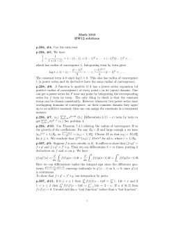
OPERATOR’S MANUAL & INSTRUCTIONS
NUMBER 2
Di-Acro
Hand Bender
Di-Acro, Incorporated
PO Box 9700
Canton, Ohio 44711
3713 Progress Street N.E.
Canton, Ohio 44705
330-455-1942
330-455-0220 (fax)
Revised 01/02
Sale or distribution of manuals is strictly prohibited
without the express written consent of Di-Acro, Incorporated
#2 BENDER ASSEMBLY
NUMBER 2 DI-ACRO BENDER
ASSEMBLY 8120800-080
2
#2 BENDER PARTS
DESCRIPTION
ITEM
1
2
3
5
6
7
8
9
10
11
12
13
14
15
16
17
18
19
20
21
22
23
24
25
26
27
28
29
30
31
35
36
38
39
40
41
42
43
44
PART NUMBER
BENDER #2
8120800-080
BASE
HANDLE ARM WLDMT
NAMEPLATE
GREASE FITTING
HANDLE UPPER (PURCHASED SEPARTELY)
HANDLE LOWER (PURCHASED SEPARTELY)
SCREW (PURCHASED SEPARTELY)
NUT (PURCHASED SEPARTELY)
MOUNTING PLATE
NEEDLE ROLLER
SHIMS
PIN
SCREW
NOSE HOLDER
NOSE PIN
SCREW
TRIGGER
PIN
STEEL BALL
SPRING
TRIGGER PIN STOP
NOSE SPRING
SCREW
SCREW
FORMING NOSE
SCREW
WASHER
SCREW
NOSE HOLDER SUPPORT
BEND LOCATING GAUGE
RADIUS PIN
LOCKING PIN ASSEMBLY
HOLDING PIN
ANGLE GAUGE
SCREW
WASHER
NUT
RETURN STOP
SCREW
8120110-100
8220120-800
3
8901004-000
8120120-800
8020120-800
22CXXX08C1102
31XX08F
8120110-501
8310301-200
8120570-203
8120111-201
20A0308C1102
8220121-701
8120120-301
20A0516C0102
8120121-702
18A0104X3000
0010461-000
8120510-202
8120313-300
8120510-401
21A0516C0102
22B0104F0508
8020121-701
21A0102F2000
61X0102
21A0102F1304
8120121-701
0124352-100
8120016-970
8120120-370
8120120-303
8120142-001
21A0308C2102
61X0308
30X0308C
8100142-001
21A0308C2104
QTY
1
1
2
1
1
1
2
2
1
97
6
2
3
1
1
1
1
1
1
1
2
2
2
1
1
1
3
2
1
1
1
1
1
2
2
3
1
1
1
#2 BENDER
QUIK-LOK ASSEMBLY
ASSEMBLY
8126111-373
THE ART OF BENDING
CAUTION
TO PREVENT SERIOUS BODILY INJURY
AND DAMAGE TO THE MACHINE
FOR A COMPLETE DESCRIPTION OF 20 BENDING
OPERATIONS WITH CLEAR STEP-BY-STEP ILLUSTRATIONS OF EACH, ORDER THE 20-PAGE DIACRO “ART OF BENDING” CATALOG WITH OVER
90 DIAGRAMS AND CHARTS TOGETHER WITH
VALUABLE TOOLING SUGGESTIONS.
BOLT THE MACHINE TO THE STAND
AND THE STAND TO THE FLOOR
4
#2 BENDER
QUIK-LOK PARTS
ITEM
1
2
3
4
5
6
7
8
9
10
11
12
13
14
15
16
17
18
19
20
21
22
23
DESCRIPTION
PART NUMBER
QUIK-LOK #2 BENDER
BASE
SLIDE
PIN
SCREW
SCREW
SCREW
WASHER
NUT
KNR HEAD SCREW
HANGER
HANDLE BLOCK
HANDLE ROD
PLASTIC KNOB
LINK
LINK PIN
PIN
PIN
NOSE ASSEMBLY
SCREW
SPACER ROD A
SPACER ROD B
SPACER ROD C
SCREW
8126111-373
8126111-300
8300111-300
19A0104X1000
20C0104F004
21A0308C1304
21A0308C2304
61X0308C1332
30X0308C
8500111-301
8126111-302
8400111-300
8500111-300
8120810-700
8930111-300
8156120-301
19A0102X2102
19A0508X2102
8920111-300
20A0516C0508
8156111-301
8300111-301
8400111-301
21A0308C2102
5
QTY
1
1
2
4
1
2
3
2
1
1
1
1
1
2
1
1
1
1
2
1
1
1
1
#2 BENDER TOOLING
DESCRIPTION
PART NUMBER
SIZE
BUILT-UP NOSE
8120250-000
3” HT.
FORMING ROLLER
8120690-000
3” DIA.
8120000-920
8120002-920
8120004-920
8120006-920
0” R.
1/16” R.
1/8” R.
3/16” R.
8120004-970
8120006-970
8120008-970
8120010-970
8120012-970
8120014-970
8120016-970
8120018-970
8120020-970
8120022-970
8120024-970
8120026-970
8120028-970
1/8” R.
3/16” R.
1/4” R.
5/16” R.
3/8” R.
7/16” R.
1/2” R.
9/16” R.
5/8” R.
11/16” R.
3/4” R.
13/16” R.
7/8” R.
8120030-930
8120100-930
8120102-930
8120104-930
8120106-930
8120108-930
8120110-930
8120112-930
8120114-930
8120116-930
8120118-930
8120120-930
8120122-930
8120124-930
8120126-930
8120128-930
8120130-930
8120200-930
15/16” R.
1” R.
1-1/16” R.
1-1/8” R.
1-3/16” R.
1-1/4” R.
1-5/16” R.
1-3/8” R.
1-7/16” R.
1-1/2” R.
1-9/16” R.
1-5/8” R.
1-11/16” R.
1-3/4” R.
1-13/16” R.
1-7/8” R.
1-15/16” R.
2” R.
8120012-790
8120014-790
8120016-790
8120020-790
8120024-790
8120008-790
8120012-790
TUBE DIA.
3/8”
7/16”
1/2”
5/8”
3/4”
1/4” I.P.S.
3/8” I.P.S.
RADIUS BLOCK
RADIUS PIN
RADIUS COLLAR
GROOVED ROLLER
6
#2 BENDER TOOLING
DESCRIPTION
FOLLOW BLOCK
GROOVED RADIUS COLLAR STYLE A
(USE WITH QUIK-LOK CLAMP)
CLAMP BLOCK
(USE WITH QUIK-LOK CLAMP)
PART NUMBER
8136012-622
8126012-623
8126012-624
8126014-622
8126014-623
8126014-624
8126016-622
8126016-623
8126016-624
8126020-622
8126020-624
8126020-625
8126024-623
8126024-624
8126024-625
8126008-622
8126008-623
8126008-624
8126012-622
8126012-623
8126012-625
8126100-012
8126200-012
8126300-012
8126104-014
8126200-014
8126300-014
8126108-016
8126200-016
8126300-016
8126124-020
8126300-020
8126400-020
8126200-024
8126300-024
8126400-024
8126116-008
8126200-008
8126300-008
8126124-012
8126300-012
8126400-012
8120012-320
8120014-320
8120016-320
8120020-320
8120024-320
8120008-320
8120012-320
7
SIZE
LENGTH
6”
9”
12”
6”
9”
12”
6”
9”
12”
6”
12”
15”
9”
12”
15”
6”
9”
12”
6”
12”
15”
C/L RADIUS
1”
2”
3”
1-1/8”
2”
3”
1-1/4”
2”
3”
1-3/4”
3”
4”
2”
3”
4”
1-1/2”
2”
3”
1-3/4”
3”
4”
TUBE DIA.
3/8”
3/8”
3/8”
7/16”
7/16”
7/16”
1/2”
1/2”
1/2”
5/8”
5/8”
5/8”
3/4”
3/4”
3/4”
1/4” I.P.S.
1/4” I.P.S.
1/4” I.P.S.
3/8” I.P.S.
3/8” I.P.S.
3/8” I.P.S.
TUBE DIA.
3/8”
3/8”
3/8”
7/16”
7/16”
7/16”
1/2”
1/2”
1/2”
5/8”
5/8”
5/8”
3/4”
3/4”
3/4”
1/4” I.P.S.
1/4” I.P.S.
1/4” I.P.S.
3/8” I.P.S.
3/8” I.P.S.
3/8” I.P.S.
TUBE DIA.
3/8”
7/16”
1/2”
5/8”
3/4”
1/4” I.P.S.
3/8” I.P.S.
BENDER TOOLING
BENDER TOOLING
SPECIAL TOOLING FOR YOUR SPECIAL BENDING NEEDS
When you have a bending problem in production or design, Di-Acro can aid you at no obligation.
Just send blueprints, dimensioned sketches, or the part you wish to produce to our Applications
Engineering Department and your plans will receive prompt attention.
Special tooling? Here is some tooling we have available: Crush-bend tooling, automatic follow-bar
return, wiper dies and ball mandrels for thin-walled tight radius tube bending, power clamping for
high speed application, pneumatic mandrel extractor.
SPRING BACK - When determining the size of the Radius Pin or Collar, spring-back should be
compensated for. A frequent way is by overbending slightly beyond the required angle. After the
amount of spring-back has been determined, the Angle Gauge can be set so that all bends will be
duplicated. In addition to overbending, it may be necessary, in some cases, to form the material
around a Radius Pin or Radius Collar of smaller radius than the desired bend. The actual size of th
Radius Pin or Collar can best be determined by experiment for the material and conditions.
FORMING ROLLER - To eliminate work marking and reduce operator effort, it is often desirable
to replace the Forming Nose (furnished as standard equipment), with a Forming Roller.
BUILT-UP FORMING NOSE - This is used to increase the material width range of Di-Acro
Benders. Must be used with wider or stacked radius collars.
There are two tube bending methods:
1. The “Forming Roller” method is recommended for (a) all large bends where centerline radius is
at least 4 times the outside diameter (O.D.) of the tube, (b) pipe and heavy wall tubing, and (c) very
small diameter tubing.
2. The “Follow Block” method, which allows forming thin wall tubing to a centerline radius as small
as 2-1/2 times the O.D. without using inside madrels or fillers.
Guard against spring-back (see above). To prevent the tube form slipping during forming, the QuikLok Clamp is recommended, used with Type A Radius Collar. For locking smaller size tubing the
Clevis and Swivel Clamps with Type B Radius Collars are used on No. 1 and No. 1A Benders.
” BENDING METHOD Grooved Radius
PARTS REQUIRED FOR “ FORMING ROLLER”
Collar - one for every radius and tube size. Grooved Forming Roller - one for each tube size only.
Clamp Block - for use with Quik-Lok Clamp on all Di-Acro Benders. One for each tube size.
Swivel and Clevis Clamps - for No. 1 and No. 1A Benders. One for each tube size.
” BENDING METHOD Grooved Radius Collar
PARTS REQUIRED FOR “ FOLLOW-BLOCK”
- one for every radius and tube size. Forming Roller - one covers all “Follow Block” operations.
Follow Block - one for each tube size only. Listed length will accommodate a 180 degree bend.
Clamp Block - for use with Quik-Lok Clamp on all Di-Acro Benders. One for each tube size. Swivel
and Clevis Clamps - for No. 1 and No. 1A Benders. One for each tube size. Style B collars only.
8
IT’S EASY TO BEND...
IT’S EASY TO BEND
Increased knowledge of the cold bending of metal and improvements in bending machines
during the past decade have opened new horizons in the manufacturing field as many
forming operations not considered practical some years ago can now be readily performed.
Technically metal bending is rather involved due to the physical change that occurs
within the material during the bending operation and also because the numerous types of
alloys available each react differently when formed.
Rather that discuss these technical problems, the purpose of this booklet is to illustrate and describe the multitude of bending operations that can easily be accomplished
without special engineering knowledge provided a few elementary principles are observed.
PRODUCT DESIGN
Design of the formed parts in a product generally determines whether or not they can be
efficiently and economically produced. Give careful consideration to these suggestions.
Selection of material is of first importance as it must be sufficiently ductile to produce
a satisfactory bend of the smallest radius required and still be strong enough to provide the
rigidity which the product demands.
It is usually desirable to designate the largest practical radius as this gives wider
latitude in choice of material and often assures a better bend in both strength and appearance.
By using the same size material and designating identical radii for each bend whenever possible, the tooling of the bending machine can be simplified and the highest possible production obtained as a number of successive bends can then be progressively
made in a part, thereby completing it before it is removed form the machine.
Compound bends or adjacent bends in different planes should be avoided if possible
because of confliction that may occur between the bends which might necessitate special
tooling. This is especially true in tubing but also holds for solid materials.
Generally the smallest recommended radius for tubing, measured to the exact center of the tube, is 1-1/2 times the outside diameter of the tube provided an inside mandrel is
used when bending. This minimum centerline radius should be increased to at least 2-1/2
times the outside diameter of the tube if the bend is to be made without an inside madrel.
In making a bend near the end of a tube, a straight length equal to at least the diameter of the tube should extend beyond the bend. If a bend is required to the very end of the
tube, a straight length should be allowed and trimmed after forming.
SELECTION OF MATERIAL
From the numerous types of material available in tubing, extrusions, mouldings, channel
and solid bars, the most suitabel material for produciton of a part can usually be chosen.
9
IT’S EASY TO BEND...
In making this selection the ductility of the material should be given prime consideration and before a decison is made a sample should be formed to the smallest required
radius or assurance obtained from the supplier that the bend can be satisfactorily made.
Elasticity of the material, which causes it to spring back after it has been bent, must
also be considered as it may be impossible to form a closed eye or a complete circle is
some alloys.
If tubing is to be bent without an inside mandrel the heaviest practical wall should be
used. As a rule, in non-ferrous metals, one quarter to half hard tubing provides best results.
When bending channels, angles, mouldings, and extrusions the centerline radius of
the bend should usually be at least three times the width of the flange to be formed edgewise.
CHOICE OF BENDING MACHINE
A number of bending machines are offered on the market today and your choice of the
most suitable bender can largely be determined by the range of your bending requirements.
These machines are available in both small and large manually operated models as
well as power driven units; some designed for one specific application and otheres capable
of performing a wide variety of operations.
Should your work consist only of one specialized operation such as the bending of
thin wall tubing on a high speed basis, obviously a completely automatic bender is the
answer.
If, on the other hand, your jobs are so varied that you are called on to form a variety
of materials such as tubing, angle, channel, extrusions, mouldings, and bus bars in addition
to solid materials, a universal all-purpose bender will best serve your needs.
Oftentimes small parts can be formed faster and cheaper with manually operated
benders provided production quantities do not warrant completely automatic equipment.
Careful study of specifications, capacities and working range of the various benders
under consideration will enable you to choose the most logical unit for your own operations.
TOOLING THE BENDER
All bending machines merely provide a means of applying power either manually or mechanically to perform the bending operation and supply mountings for the bending tools.
These tools consist of a form or radius collar having the same shape as the desired
bend, a clamping block or locking pin that securely grips the material during the bending
operation and a forming roller or follow block which moves around the bending form.
When bending materials of open cross section such as tubing, channel, angle and
extrusions, the bending form should exactly fit the contour of the material to provide support
during ther forming operation. This is also true of the clamping block and forming roller, as
only by completely confining the material can a perfect bend be obtained.
Since all metals are somewhat elastic, they will spring back more or less after they
are formed and for that reason the bending form must usually have a smaller radius than
the required bend. The amount of springback is dependent upon the type of material, its
size and hardness, as well as the radius of the bend and it is usually necessary to experiment somewhat to determine the exact size of the bending form.
Bending is no different than any machining operation in that the results obtained will
be in direct proportion to the care taken in properly tooling the bender for the job to be
done.
10


© Copyright 2026