
Negative capacitance in GaN/AlGaN heterojunction dual
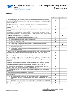
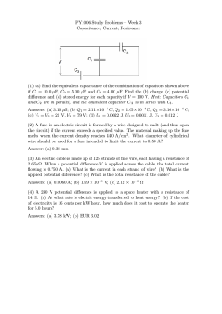
JOURNAL OF APPLIED PHYSICS 106, 053701 共2009兲 Negative capacitance in GaN / AlGaN heterojunction dual-band detectors L. E. Byrum,1 G. Ariyawansa,1 R. C. Jayasinghe,1 N. Dietz,1 A. G. U. Perera,1,a兲 S. G. Matsik,2 I. T. Ferguson,3 A. Bezinger,4 and H. C. Liu4 1 Department of Physics and Astronomy, Georgia State University, Atlanta, Georgia 30303, USA NDP Optronics LLC, Mableton, Georgia 30126, USA 3 School of Electrical and Computer Engineering, Georgia Institute of Technology, Atlanta, Georgia 30032, USA 4 Institute for Microstructural Sciences, National Research Council, Ottawa K1A 0R6, Canada 2 共Received 22 May 2009; accepted 22 July 2009; published online 2 September 2009兲 A study of trap states in n+-GaN / AlGaN heterostructures using electrical, thermal, and optical analyses is reported. Capacitance-voltage-frequency measurements showed negative capacitance and dispersion, indicating interface trap states. Infrared spectra identified three impurity related absorption centers attributed to shallow Si-donor 共pinned to the AlGaN barrier兲, N-vacancy/ C-donor, and deep Si-donor 共pinned to the GaN emitter兲 impurities with corresponding activation energies of 30.8⫾ 0.2, 125⫾ 1, and 140⫾ 2 meV, respectively. The shallow Si-donor impurity had a relaxation time of 155⫾ 9 s, while the C-donor/N-vacancy and deep Si-donor impurities appear to behave as a single trap state with a relaxation time of 1.77⫾ 0.05 s. Multiple analysis techniques allowed the determination of the activation energies of these impurity related centers and the study of the effects of trap states on the electrical behavior of the detector. © 2009 American Institute of Physics. 关doi:10.1063/1.3211292兴 I. INTRODUCTION II. EXPERIMENT Radiation-hard, solar blind, high-speed optoelectronic devices have been developed based on gallium nitride device structures.1 Previously developed GaAs/ AlGaAs detectors provided efficient operation in a wide range of infrared 共IR兲 wavelengths.2–4 With the advent of GaN based materials, detectors have been developed,5 which operate simultaneously in both the IR and ultraviolet 共UV兲 ranges. Capacitance measurements allow the determination of charge distribution and the identification of the presence of interface states in semiconductors, as an applied bias contributes to carrier capture and emission at interface trap states. These traps will be charged and, thus, produce a dipole layer in the vicinity of the interface.6 Small modulations in ac bias will cause a change in the barrier height, and the position of the Fermi level will shift relative to its equilibrium position, thus, changing the characteristics of the detector. Here, the effects of trap states on the capacitance-voltage 共C-V兲 and capacitance-frequency 共C-f兲 characteristics of n+-GaN / AlxGa1−xN detectors are reported. While the measurements reveal the location and mechanisms by which the defect states operate, other methods of analysis are needed to identify the sources of the trap states. IR spectroscopy revealed three impurity related absorption centers that were identified as N-vacancy, C-donor, and Si-donor. The components of the trapping mechanisms, which responded to thermally assisted tunneling, could be discerned from thermal activation energies obtained from an Arrhenius plot. Thus, using multiple methods for the analysis of trap states indicated changes in the electrical behavior due to the presence of trap states, along with the identification of the mechanisms by which the trap states operated. The n+-GaN / Al0.026Ga0.974N structures 共sample 1158兲 were grown by low pressure metal-organic chemical vapor deposition on c-plane sapphire substrates. The UV/IR dualband detector structure, depicted in Fig. 1, consists of a n+-GaN top-contact emitter layer, an Al0.026Ga0.974N barrier layer, and a n+-GaN bottom-contact layer. The Al0.026Ga0.974N barrier layer had an Al fraction of 0.026, which introduces a work function of 88 meV. Both contact layers were n+-doped with silicon to a doping concentration of 5 ⫻ 1018 cm−3. Due to the high doping concentration of all n+-GaN contact layers, the contact layers can be treated as a semimetal since the doping concentration is greater than the a兲 Electronic mail: [email protected]. 0021-8979/2009/106共5兲/053701/5/$25.00 (a) (b) n+-GaN Metal Rectangular Contacts n+ -GaN Emitter Al0.026Ga0.974N Barrier 0.2 m Al0.026Ga0.974N 0.6 m n+ -GaN Bottom Contact Sapphire Substrate 0.7 m Metal Rectangular Contact FIG. 1. 共Color online兲 共a兲 The structure of the detectors consists of an undoped Al0.026Ga0.974N layer located between a n+-GaN top-contact 共emitter兲 layer and a bottom-contact layer. Both n+-GaN layers were n+-doped with Si to a concentration of 5 ⫻ 1018 cm−3. When forward biased, the topcontact was positive and the bottom-contact was negative. The emitter layer was fully etched; the barrier and the bottom-contact layers were the same regardless of the etching process. 共b兲 Top view of the structure showing the metal rectangular contact. The emitter region inside the rectangular contacts has been fully etched. IR detection takes place by free carrier absorption, while the UV response is due to the interband transitions. 106, 053701-1 © 2009 American Institute of Physics 1158 77 K (a) 0 -1 -2 1kHz 10kHz 100kHz 500kHz 1MHz -1 0 1 2 Bias Voltage (V) 2 (b) 1158 77 K Capacitance (pF) 1 Capacitance (nF) J. Appl. Phys. 106, 053701 共2009兲 Byrum et al. Capacitance (nF) 053701-2 -2 V 30 0 4 10 5 10 6 10 Frequency (Hz) 0 -2 1547 77 K 60 -2 V -1 V 0V +1 V +2 V 10 4 10 5 10 6 Frequency (Hz) FIG. 2. FDCD and negative capacitance were observed in both the 共a兲 C-V profile and 共b兲 C-f profile of the n+-GaN / Al0.026Ga0.974N structure 共sample 1158兲. From the C-f profile, inverse relaxation times of approximately 1.77⫾ 0.05 and 155⫾ 9 s were calculated from the points where the capacitance transitioned from negative to positive or from positive to negative. The inset shows a C-f profile of the n+-GaN / Al0.1Ga0.9N structure 共sample 1547兲. only result in positive capacitance, as the total electric current is due solely to the displacement current and there is no contribution from a conduction current. Only in specific cases 共high frequency or low temperature兲 can the capacitance be described by the electrostatic approximation, referred to as the geometric capacitance C0. The geometric capacitance for a 600⫻ 600 m2 mesa area is ⬃2.9 pF. In order to describe the negative capacitance in terms of transient currents7, capacitance must be defined in terms of the imaginary part of the total admittance Y共兲, C共兲 = 1 1 Im关Y共兲兴 = ⌬V 冕 ⬁ ␦J共t兲cos共t兲dt. 共2兲 0 When the transient current J共t兲, transient relaxation current Mott transition in GaN 共 ⬃ 8 ⫻ 1017 cm−3兲. Thus, the n+-GaN / Al0.026Ga0.974N interface is analogous to a metalsemiconductor interface. Using dry etching techniques, the structures were processed to form square mesas with the areas inside the metal rectangular contact fully etched. However, the n+-GaN layer under the rectangular contact remained intact 共0.2 m thick兲, thus, a small n+-GaN / Al0.026Ga0.974N heterojunction would still be present at the top-contact/barrier interface. The UV/IR dual-band detector operates by collecting carriers from both intraband IR transitions in the n+-GaN emitter layer and interband UV transitions in the Al0.026Ga0.974N barrier layer, as discussed in detail elsewhere.5 Etching the topcontact emitter will drastically reduce the IR active region of the sample; however, the n+-GaN layer under the rectangular contact will remain intact between the metal contact and the Al0.026Ga0.974N barrier. C-V and C-f measurements were carried out using a computer-controlled Hewlett-Packard 4284A LCR meter. C-V scans were taken from −2 to + 2 V with a 50 mV step width and sine output amplitude set at 5 mV from 100 Hz to 1 MHz, while the C-f scans were taken between 1 kHz and 1 MHz. When forward biased, the top-contact was positive and the bottom-contact was negative. Under reverse bias, the top-contact was negative and the bottomcontact was positive. Different aspects of the electrical behavior can be studied using C-V and C-f characteristics. The applied voltage can either be held constant, and the ac frequency varied or the frequency can be held constant and the applied voltage varied. In the C-V profiles 共see Fig. 2兲, negative capacitance was observed at frequencies of 10– 500 kHz, which falls in the range of ⬃6 – 600 kHz where negative capacitance occurred in the C-f profiles. III. RESULTS AND DISCUSSION When described in terms of charge accumulation at an interface, the capacitance is defined in terms of electrostatics, C0 = 0A , L 共1兲 where is the relative dielectric permittivity, 0 is the dielectric permittivity in a vacuum, A is the mesa area, and L is the thickness of the barrier layer. However, this description can ␦ j共t兲, and geometric capacitance C0 are included, the capaci- tance is described7 by C共兲 = C0 + 1 ⌬V 冕 ⬁ 0 − d␦ j共t兲 sin共t兲dt. dt 共3兲 In Eq. 共3兲, the sign of the second term is dependent on both the frequency and the behavior of the transient relaxation current in the time domain, specifically, the time derivative. In response to a small voltage step ⌬V, if ␦ j共t兲 exhibits a positive-valued behavior 共as reported7 in cases of impact ionization of impurities and other interface effects兲 and the magnitude is greater than C0, then the integral in Eq. 共3兲 will become negative, resulting in a negative capacitance. Frequency-dependent capacitance dispersion 共FDCD兲 was observed in the C-V profiles, as shown in Fig. 2共a兲, and has been attributed to the presence of frequency-dependent trap states. Such phenomena have been observed in the 10 kHz– 1 MHz regions of other GaN / AlGaN heterojunctions such as Schottky diodes8 and heterojunction field effect transistors.9 In addition to FDCD, negative capacitance was observed in the C-V profiles of the n+-GaN / Al0.026Ga0.974N samples for frequency values of 10, 100, and 500 kHz. Negative capacitance has been observed in various other detector structures.6,10,11 The phenomenon has been attributed to carrier generation and recombination at interface states, most likely due to the presence of occupied trap states at the emitter-intrinsic layer interface.6 Due to the symmetry in the C-V profiles for both forward and reverse biasing, it is assumed that the processes responsible for negative capacitance and FDCD are present at both heterointerfaces. The band diagram, including the location of the defect states under zero bias 共in addition to the detection mechanism兲, is shown in Fig. 3共a兲. In the figure, the n+-GaN topcontact is to the left of the intrinsic Al0.026Ga0.974N barrier layer and the n+-GaN bottom-contact is to the right; the diagram is intended to show the area between metal contacts. When a bias is applied across the device, as shown in Fig. 3共b兲, electrons with sufficient energy will either surmount the barrier or fill up any available trap states at the emitterbarrier interface. However, under certain frequency and bias conditions, electrons that possess sufficient energy will be able to dislocate any electrons already present in trap states below the Fermi level in a process similar to impact ioniza- 053701-3 (a) J. Appl. Phys. 106, 053701 共2009兲 Byrum et al. (b) shallow Si-donor Top Contact Bottom Contact C-donor/ N-vacancy deep Si-donor n+-GaN Al0.026Ga0.974N Top Contact Bottom Contact (+) (-) e- EF EC EV n+-GaN n+-GaN n+-GaN Al0.026Ga0.974N FIG. 3. 共Color online兲 共a兲 The band diagram showing the location of defect energy states of the n+-GaN / Al0.026Ga0.974N detector structure under zero bias. 共b兲 Schematic showing the mechanism leading to negative capacitance 共with no external radiation兲. When the sample was reverse biased 共topcontact is to the left of the barrier, bottom-contact to the right兲, electrons with sufficient energy were able to initiate an impact ionizationlike process by dislocating filled electron recombination centers below the Fermi level at the heterointerface. tion or the Auger effect. These ionized trap states then act as electron recombination centers. In a n+-doped semiconductor, the relaxation times of electron recombination centers below the Fermi level are faster than those of the trap states above the Fermi level due to the excess of available electrons. When the electron occupancy of states below the Fermi level exceeds the occupancy of electrons above the Fermi level, the interface charge density variation is reversed and the capacitance becomes negative. The negative capacitance observed in the C-f profiles, as seen in Fig. 2共b兲, allowed for the extrapolation of trap state relaxation times. The transitions from positive to negative capacitance occurred around 6 kHz, while the transition from negative to positive capacitance was at ⬃600 kHz. These two frequencies correlate with f −1 relaxation times of 155⫾ 9 and 1.77⫾ 0.05 s, respectively. The faster relaxation time can be attributed to trap states below the Fermi level, possibly C-donor/N-vacancy and deep Si-donor defect states 共pinned to the n+-GaN emitter layer兲, and the slower relaxation time to trap states above the Fermi level is probably due to shallow Si-donor states in the Al0.026Ga0.974N barrier layer. At frequencies less than 6 kHz, both generation and recombination processes occur; however, the dominant trap states 共shallow Si-donor兲 are located above the Fermi level and, consequently, the capacitance is positive. At ⬃6 kHz the trap states associated with a long relaxation time 共slow trap states兲 are saturated and the electron recombination centers exhibiting short relaxation times 共fast trap states兲 become dominant, thus, producing a negative capacitance. The fast trap states remain active until ⬃600 kHz, above which these trap states also become saturated. Once both generation and recombination processes have become inactive, due to high frequency, the capacitance returned to a positive value and approached the geometrical capacitance of the sample. In order to model the C-f curves, the contributions from both majority and minority carriers are incorporated by including7 both positive and negative exponential components into the transient response current. The corresponding capacitance calculated from Eq. 共3兲 is then FIG. 4. 共a兲 IR spectra showing two impurity related absorption centers with transitional energies of 93.4⫾ 0.5 and 105⫾ 1.5 meV, corresponding to activation energies of 125⫾ 1 and 140⫾ 2 meV. These absorption centers were attributed to N-vacancy/C-donor and deep Si-donor defect states, respectively. 共b兲 A third absorption center was observed in the IR spectra with a 1s-2p transitional energy of 23.1⫾ 0.1 meV. This absorption center was attributed to shallow Si-donor impurities in the Al0.026Ga0.974N barrier layer with an activation energy of 30.8⫾ 0.2 meV. C共兲 = C0 + a 1 1 a 2 2 − , 1 + 共 1兲 2 1 + 共 2兲 2 共4兲 where a1 and a2 are constants and 1 and 2 are the relaxation times of the majority and minority carriers, respectively. Relaxation times 1 = 140⫾ 20 s and 2 = 1.74⫾ 0.10 s were found using Eq. 共4兲 and were in agreement with the f −1 relaxation times from the C-f profiles. However, the amplitude of the C-f profiles could not be fitted using a Debye relaxation model, indicating that non-Debye processes are active in the sample. In the high-frequency limit 共 → ⬁兲, the capacitance will approach the geometric capacitance of the sample due to finite inertia of the carrier transport processes when both the faster and slower traps can no longer respond. The broad peak response peak observed in the IR spectra 共see Fig. 4兲 between 8 and 14 m is due to free carrier absorption. However, absorption peaks related to impurity transitions are observed superimposed on the free carrier response between 11 and 13.6 m. Based on previous reports,12–14 the three impurity related absorption peaks were attributed to shallow Si-donor impurities in the Al0.026Ga0.974N barrier layer with a 1s-2p transitional energy of 23.1⫾ 0.1 meV, which corresponds to an activation energy of 30.8⫾ 0.2 meV. C-donor and/or N-vacancy impurities were attributed to the transitional energy of approximately 93.4⫾ 0.5 meV, which correspond to an activation energy of 125⫾ 1 meV. The third peak with a transitional energy of 105⫾ 1.5 meV and activation energy of 140⫾ 2 meV is attributed to Si-donor impurities at the heterointerface, which are pinned to the impurity band in the n+-GaN emitter layer. The conduction band offset of the n+-GaN / AlGaN heterointerface was calculated to be 137⫾ 7 meV, which is consistent with the activation energy of 140⫾ 2 meV. To confirm that the negative capacitance displayed by the n+-GaN / Al0.026Ga0.974N sample was due to the presence of C-donor/N-vacancy and deep Si-donor defect states below 053701-4 J. Appl. Phys. 106, 053701 共2009兲 Byrum et al. TABLE I. Summary of the experimentally obtained parameters and corresponding defect states. The activation energies were calculated from IR spectra transitional energies. Because the states below the Fermi level behave as a single trap state, the relaxation times are the same. The conduction band offset due to shallow Si-donor states 共pinned to the n+-GaN emitter兲 was calculated to be 137⫾ 7 meV. Impurity Shallow Si-donor C-donor/N-vacancy Deep Si-donor Position Above EF 共pinned to AlGaN兲 States below EF States below EF 共pinned to GaN兲 the Fermi level, and not the shallow Si-donor states in the Al0.026Ga0.974N barrier layer, a similar n+-GaN / Al0.1Ga0.9N structure 共sample 1547兲 was used to obtain thermal activation energies. The n+-GaN / Al0.1Ga0.9N structure had the same Si doping concentration 共5 ⫻ 1018 cm−3兲 and shallow Si-donor activation energy 共from IR spectra兲 as the n+-GaN / Al0.026Ga0.974N structure, but did not exhibit negative capacitance as the position of the C-donor and N-vacancy defect states were above the Fermi level due to an increased Al fraction.15 For comparison, a C-f profile from the n+-GaN / Al0.1Ga0.9N sample is provided in the inset of Fig. 2共b兲. Thus, an Arrhenius plot could be constructed using C-f relaxation times at temperatures ranging from 50 to 166 K and a thermal activation energy of 15⫾ 1 meV was obtained for the n+-GaN / Al0.1Ga0.9N structure. Other groups reported16 similar thermal activation energies of 12– 17 meV for shallow Si-donor impurities in GaN structures. The energy difference of approximately 16⫾ 1 meV between the activation energy estimated by IR spectroscopy and the thermal activation energy obtained from the Arrhenius plot indicates that the shallow Si-donors contribute to carrier transport through both thermionic emission and thermally assisted tunneling due to barrier thinning. The discrepancy between these two activation energy values is due to the fact that an Arrhenius plot provided the thermal activation energy required for the particle to reach an excited boundstate energy level where thermally assisted tunneling could take place through the potential barrier. In the case of thermally assisted tunneling, the activation energies obtained by an Arrhenius plot will therefore be lower than the activation energies obtained by IR spectroscopy, as observed here. Combining the present experimental data, summarized in Table I, a comprehensive model including impurity trap states for n+-GaN / Al0.026Ga0.974N heterostructure can be constructed. The fast trap states are tentatively assigned to C-donor/N-vacancy and deep Si-donor defect states at the heterointerface positioned below the Fermi level, while the slow trap states appear to be correlated with shallow Sidonor impurities in the barrier layer positioned above the Fermi level. C-donor and N-vacancy related impurities are known to be incorporated into the material from the utilized organic precursors,5 such as the trimethylgallium 共TMGa兲 or trimethylaluminum 共TMAl兲 used as the Ga and Al precursors, respectively, and defects in the crystalline structure. Si- Relaxation times 共s兲 Optical Eactivation 共meV兲 Expt. Calc. 30.8⫾ 0.2 155⫾ 9 140⫾ 20 125⫾ 1 1.77⫾ 0.05 1.74⫾ 0.10 140⫾ 2 1.77⫾ 0.05 1.74⫾ 0.10 donor related impurities are due to dopant migration from the top- 共or bottom-兲 contact layers. The concentration of Sidonor traps have been found to correlate with Si-dopant incorporation during the growth process.16 IV. CONCLUSION In summary, using C-V and C-f characterizations, negative capacitance and FDCD of n+-GaN / Al0.026Ga0.974N heterostructures were analyzed. Using both IR spectroscopy and thermal activation energies, the fast trap states are attributed to deep Si-donor and C-donor/N-vacancy defect states located at the n+-GaN / Al0.026Ga0.974N heterointerface with activation energies of approximately 140⫾ 2 and 125⫾ 1 meV, respectively; and the slow trap states are attributed to shallow Si-donor states located in the Al0.026Ga0.974N barrier layer at the heterointerface with an activation energy of 30.8⫾ 0.2 meV and a thermal activation energy of 15⫾ 1 meV. Calculated 共140⫾ 20 and 1.74⫾ 0.10 s兲 and f 1 共155⫾ 9 and 1.77⫾ 0.05 s兲 relaxation times were consistent to within the degree of uncertainty, with the f 1 relaxation times having a smaller uncertainty owing to the electron recombination center’s non-Debye relaxation mechanism. Although multiple methods of determining activation energies allow for the identification of impurity traps, the additional use of C-V and C-f measurements provides information about the effects these trap states have on the electronic and optical properties of n+-GaN / AlxGa1−xN detectors. ACKNOWLEDGMENTS This research was supported in part by the US Air Force under Small Business Innovation Research Program 共SBIR兲 Contract No. FA9453-06-C-005, the Georgia Research Alliance, and GSU MBDAF. The authors would like to acknowledge Dr. Dave Cardimona and Dr. Bill Glass for fruitful discussions. 1 E. Munoz, E. Monroy, J. L. Pau, F. Calle, F. Omnes, and P. Gibart, J. Phys.: Condens. Matter 13, 7115 共2001兲. M. P. Touse, G. Karunasiri, K. R. Lantz, H. Li, and T. Mei, Appl. Phys. Lett. 86, 093501 共2005兲. 3 J. Li, K. K. Choi, and D. C. Tsui, Appl. Phys. Lett. 86, 211114 共2005兲. 4 M. B. M. Rinzan, A. G. U. Perera, S. G. Matsik, H. C. Liu, Z. R. Wasilewski, and M. Buchanan, Appl. Phys. Lett. 86, 071112 共2005兲. 5 G. Ariyawansa, M. B. M. Rinzan, M. Alevli, M. Strassburg, N. Dietz, A. G. U. Perera, S. G. Matsik, A. Asghar, I. T. Ferguson, H. Luo, A. Bez2 053701-5 inger, and H. C. Liu, Appl. Phys. Lett. 89, 091113 共2006兲. A. G. U. Perera, W. Z. Shen, M. Ershov, H. C. Liu, M. Buchanan, and W. J. Schaff, Appl. Phys. Lett. 74, 3167 共1999兲. 7 M. Ershov, H. C. Liu, L. Li, M. Buchanan, Z. R. Wasilewski, and V. Ryzhii, IEEE Trans. Electron Devices 45, 2196 共1998兲. 8 R. M. Chu, Y. G. Zhou, K. J. Chen, and K. M. Lau, Phys. Status Solidi C 0, 2400 共2003兲. 9 W. L. Liu, Y. L. Chen, A. A. Balandin, and K. L. Wang, J. Nanoelectron. Optoelectron. 1, 258 共2006兲. 10 M. Ershov, H. C. Liu, L. Li, M. Buchanan, Z. R. Wasilewski, and V. Ryzhii, Appl. Phys. Lett. 70, 1828 共1997兲. 11 X. Wu, E. S. Yang, and H. L. Evans, J. Appl. Phys. 68, 2845 共1990兲. 6 J. Appl. Phys. 106, 053701 共2009兲 Byrum et al. 12 W. J. Moore, J. A. Freitas, and R. J. Molnar, Phys. Rev. B 56, 12073 共1997兲. 13 M. Sumiya, K. Yoshimura, K. Ohtsuka, and S. Fuke, Appl. Phys. Lett. 76, 2098 共2000兲. 14 V. Bougrov, M. Levinshtein, S. Rumyantsev, and A. Zubrilov, Properties of Advanced Semiconductor Materials 共Wiley, New York, 2001兲. 15 L. E. Byrum, G. Ariyawansa, R. C. Jayasinghe, N. Dietz, A. G. U. Perera, S. G. Matsik, I. T. Ferguson, A. Bezinger, and H. C. Liu, J. Appl. Phys. 105, 023709 共2009兲. 16 W. Gotz, N. M. Johnson, C. Chen, H. Liu, C. Kuo, and W. Imler, Appl. Phys. Lett. 68, 3144 共1996兲.


© Copyright 2026