
Specifications & Dimensions AW
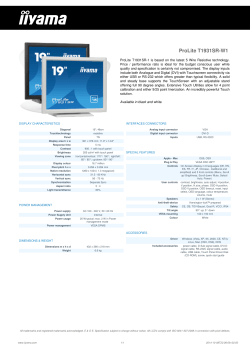
Remote Camera System – Specifications & Dimensions AW-HE40SW/SK/HW/HK Input General Power Requirements Ambient Operating Temperature DC 12 V (Supplied AC adaptor) DC 42 - 57 V (PoE+ power supply) 1.2 A (Supplied AC adaptor) 0.4 A (PoE+ power supply) 0 °C to 40 °C (32 °F to 104 °F) Power DC 12 V IN, PoE+ (IEEE802.3at standard) MIC/LINE Input Stereo mini-jack (ø3.5 mm) Input impedance: Approx. 2 kΩ (unbalanced) <.JDJOQVU>r4VQQPSUFENJDSPQIPOFT4UFSFPNJD (plug-in power,on/off switching via menu) r4VQQMJFEWPMUBHF77 r.JDJOQVUMFWFMmE#7E#7 [Line input>r*OQVUMFWFMmE#7E#7 Allowable Humidity Ranges 20 % to 90 % (no condensation) Storage Temperature –20 °C to 50 °C (–4 °F to 122 °F) Mass Approx. 1.5 kg (3.30 lb) 160 mm x 186 mm x 166 mm Dimensions (W x H x D) (6-5/16 inches x 7-41/128 inches x 6-17/32 inches) (excluding protrusions, direct ceiling mount bracket) Finish AW-HE40HW / AW-HE40SW: Pearl white AW-HE40HK / AW-HE40SK: Metallic black Controller Supported*1 AW-RP50, AW-RP120G, AK-HRP200G Output Video Output HDMI connector AW-HE40H r)%$1JTOPUTVQQPSUFE HDMI r7JFSB-JOLJTOPUTVQQPSUFE AW-HE40S Compliant with the SMPTE292M HD-SDI standards/75 (BNC x 1) Input/Output Camera Unit LAN LAN connector for IP control (RJ-45), PoE+ Equipped with straight/crossover cable auto detection function Imaging Sensors 1/2.3-type MOS Lens Motorized 30x zoom, F1.6 to F4.7[f=4.3 mm (11/64 inches) to 129 mm (5-5/64 inches); 35 mm (1-3/8 inches) equivalent: 31.6 mm (1-31/128 inches) to 962.0 mm (37-7/8 inches)] Focus Switching between auto and manual USB Mini-B port (Used for maintenance)*4 Entire zooming range: 1.2 m (3.94 ft) Wide end: 10 cm (0.33 ft) SD Card microSD card slot (Used for maintenance)*4 Focus Distance Color Separation Optical System On-chip color filter system Minimum Illumination 0.7 lx (50 IRE, F1.6, 48 dB,1/60 without accumulation) 59.94 Hz 0.35 lx (50 IRE, F1.6, 48 dB,1/30 with accumulation [Frame Mix 6 dB]) 50 Hz Horizontal Resolution 2 0.7 lx (50 IRE, F1.6, 48 dB,1/50 without accumulation) 0.35 lx (50 IRE, F1.6, 48 dB,1/25 with accumulation [Frame Mix 6 dB]) 1000 TV lines Typ (Center area) Gain Selection* Auto, 0 dB to 48 dB (3 dB step) Frame Mix*3 Auto, Off, 6 dB, 12 dB, 18 dB, 24 dB Full Auto 1/30 to 1/2000[59.94 Hz] 1/25 to 1/2000[50 Hz] Auto 1/60 to 1/2000[59.94 Hz] 1/50 to 1/2000[50 Hz] Manual 1/100, 1/250, 1/500, 1/1000, 1/2000, 1/4000, 1/10000[59.94 Hz] 1/120, 1/250, 1/500, 1/1000, 1/2000, 1/4000, 1/10000[50 Hz] Synchro Scan 59.94 Hz 59.94 Hz to 660.09 Hz (255 steps) 50.00 Hz to 570.12 Hz (255 steps) Gamma 50 Hz Off, Normal (Low, Mid, High), Cinema Electronic Shutter Speed White Balance ATW, AWB A, AWB B, 3200K, 5600K, VAR (2400K to 9900K) Chroma Amount Variability TUFQ Scene File Full Auto, Manual1, Manual2, Manual3 Color Bars FULL BAR Synchronization System Synchronization System Internal synchronization Mini DIN 8-pin (IN) Input/ RS-232C Mini DIN 8-pin (OUT) Output Connnector RS-422 CONTROL IN RS422A (RJ-45) Pan-tilt Head Unit Installation Method Stand-alone (Desktop) or suspended (Hanging)*5 Pan-tilt Operation Speed Maximum speed during preset: 300°/s Maximum speed during manual: 90°/s Panning Range Tilting Range*6 –30° to 90°*6 Quietness During preset: NC40 or less During manual: NC35 or less Camera/Pan-tilt Head Control IP connecting cable When connecting through a hub: r-"/DBCMF*7(category 5 or above),max. 100 m (328 ft) When using a PoE+ hub: r-"/DBCMF*7 (category 5e or above),max. 100 m (328 ft) When a hub is not used: r-"/DBCMF*7 (category 5 or above),max. 100 m (328 ft) AW protocol connecting cable r-"/DBCMF*7 (category 5 or above,straight cable), max. 1000 m (3280 ft) Standard protocol connecting cable r.JOJ%*/QJODBCMFNBMF Standard Accessories Mount bracket for installation surface (Hanging*8/ Desktop): 1, Drop-prevention wire mounting screw (already attached to the unit): 1, Bracket mounting screws (bind-head) M4 x 10 mm: 4, Main unit mounting screw (with flat washer, spring washer) M3 x 6 mm: 1, Power cable (1.8 m [5.9 ft]): 1, AC adaptor: 1, CD-ROM *1: It may be necessary to upgrade the version of the controller in order to support the unit. *2: During Auto, 6 dB to 48 dB (6 dB step) are available for AGC Max Gain setting. *3: During Auto, 0 dB, 6 dB, 12 dB and 18 dB are available for Auto F.Mix Max Gain setting. *4: Will be available via fee-based version upgrades. *5: To ensure safety, the unit must be secured using the mount bracketsupplied. *6: Depending on the pan or tilt position, the camera may be reflected in the image. *7: Use of an STP (shielded twisted pair) cable is recommended. *8: To ensure more safety, AW-HE40SW/SK/HW/HK can be secured by using the direct ceiling mount bracket (WV-Q105A). *For informations on "Output Signal Format", see page 26. 36 Dimensions Unit: mm(inches) AW-HE40SW (Side) 48(1-57/64) 129(5-5/64) 183(7-13/64) (Front) 160(6-5/16) Rear View AW-HE40HW 3(1/8) 80(3-5/32) 77(3-1/32) 166(6-17/32) Bottom View Unit: mm(inches) LAN cable*1(category 5 or above, straight cable), max. 1000 m (3280 ft) * Use of an STP (shielded twisted pair) cable is recommended. 130(5-1/8) (Space foe the wires from the rear panel) Hole for mounting the main unit mounting screws Hook for mounting the drop-prevention wire Unit mounting area Signal Pin NO. Signal GND TALLY RXD– TXD– 5 6 7 8 TXD+ RXD+ — — Mount bracket (* )46(1-13/16) 1 2 3 4 Through-hole for cable ø 40 mm (ø 1-9/16 inches) (reference) (* )Holes for mounting the mount bracket: ø 4.5 mm x 4 Hole for checking the positioning (* )83.5(3-9/32) 156(6-1/8) 160(6-5/16) RS-232C Connectors <RS-232C IN/OUT> Connects to an RS-232C cable. Mini Din 8-pin (JST) Hole for installing the WV-Q105A direct ceiling mount bracket [ø 60 mm (ø 2-3/8 inches)] The front panel of the unit on this side. Ceiling Installation View RS-232C OUT Pin Signal NO. 1 2 DTR_IN DSR_IN 1 2 DTR_OUT DSR_OUT 3 TXD_IN 3 TXD_OUT 4 GND 4 GND 5 RXD_IN 5 RXD_OUT 6 GND 6 GND 7 IR OUT R 7 NC 8 IR OUT L 8 NC Optimal for both hanging and desktop installation. The mounting bracket and droppreventation wire are standard accessories. Ceiling and desktop installation are both possible. Mount the bracket onto the installation surface and then put and turn the main unit on the bracket to be installed. Approx. 15° Dropprevention wire Live Switcher RS-232C IN Pin Signal NO. 78(3-1/16) 65(2-9/16) 80(3-5/32) 77 (3-1/32) 90(3-17/32) 290(11-7/16) or more (Space for the wires) RS-422 Connector <RS-422> This RS-422 connector (RJ45) is connected when exercising serial control over the unit from an external device. Use a cable with the following specifications for the connection to this connector. The tally lamp can be lit by shorting the TALLY signal (pin 2) with GND (pin 1). r%POPUBQQMZBWPMUBHFUPUIF5"--:TJHOBMQJO Remote Camera System Pin Configuration Pin NO. Studio Camera System As of May, 2015 * Wiring, mounting, and removal must be done by a qualified technician. To ensure safety, consult with the dealer from whom you purchased the system. 37


© Copyright 2026