
Wireless Network Communications Overview for Space
Report Concerning Space Data System Standards
WIRELESS NETWORK
COMMUNICATIONS
OVERVIEW FOR SPACE
MISSION OPERATIONS
INFORMATIONAL REPORT
CCSDS 880.0-G-2
GREEN BOOK
April 2015
Report Concerning Space Data System Standards
WIRELESS NETWORK
COMMUNICATIONS
OVERVIEW FOR SPACE
MISSION OPERATIONS
INFORMATIONAL REPORT
CCSDS 880.0-G-2
GREEN BOOK
April 2015
CCSDS REPORT CONCERNING INTEROPERABLE WIRELESS NETWORK COMMUNICATIONS
AUTHORITY
Issue:
Informational Report, Issue 2
Date:
April 2015
Location:
Washington, DC, USA
This document has been approved for publication by the Management Council of the
Consultative Committee for Space Data Systems (CCSDS) and reflects the consensus of
technical panel experts from CCSDS Member Agencies. The procedure for review and
authorization of CCSDS Reports is detailed in Organization and Processes for the
Consultative Committee for Space Data Systems (CCSDS A02.1-Y-4).
This document is published and maintained by:
CCSDS Secretariat
National Aeronautics and Space Administration
Washington, DC, USA
E-mail: [email protected]
CCSDS 880.0-G-2
Page i
April 2015
CCSDS REPORT CONCERNING INTEROPERABLE WIRELESS NETWORK COMMUNICATIONS
FOREWORD
This document is a CCSDS Informational Report, which contains background and
explanatory material to support the CCSDS wireless network communications Best Practices
for networked wireless communications in support of space missions.
Through the process of normal evolution, it is expected that expansion, deletion, or
modification of this document may occur. This Report is therefore subject to CCSDS
document management and change control procedures, which are defined in Organization
and Processes for the Consultative Committee for Space Data Systems (CCSDS A02.1-Y-4).
Current versions of CCSDS documents are maintained at the CCSDS Web site:
http://www.ccsds.org/
Questions relating to the contents or status of this document should be sent to the CCSDS
Secretariat at the e-mail address indicated on page i.
CCSDS 880.0-G-2
Page ii
April 2015
CCSDS REPORT CONCERNING INTEROPERABLE WIRELESS NETWORK COMMUNICATIONS
At time of publication, the active Member and Observer Agencies of the CCSDS were:
Member Agencies
– Agenzia Spaziale Italiana (ASI)/Italy.
– Canadian Space Agency (CSA)/Canada.
– Centre National d’Etudes Spatiales (CNES)/France.
– China National Space Administration (CNSA)/People’s Republic of China.
– Deutsches Zentrum für Luft- und Raumfahrt (DLR)/Germany.
– European Space Agency (ESA)/Europe.
– Federal Space Agency (FSA)/Russian Federation.
– Instituto Nacional de Pesquisas Espaciais (INPE)/Brazil.
– Japan Aerospace Exploration Agency (JAXA)/Japan.
– National Aeronautics and Space Administration (NASA)/USA.
– UK Space Agency/United Kingdom.
Observer Agencies
–
–
–
–
–
–
–
–
–
–
–
–
–
–
–
–
–
–
–
–
–
–
–
–
–
–
–
–
–
–
Austrian Space Agency (ASA)/Austria.
Belgian Federal Science Policy Office (BFSPO)/Belgium.
Central Research Institute of Machine Building (TsNIIMash)/Russian Federation.
China Satellite Launch and Tracking Control General, Beijing Institute of Tracking and
Telecommunications Technology (CLTC/BITTT)/China.
Chinese Academy of Sciences (CAS)/China.
Chinese Academy of Space Technology (CAST)/China.
Commonwealth Scientific and Industrial Research Organization (CSIRO)/Australia.
Danish National Space Center (DNSC)/Denmark.
Departamento de Ciência e Tecnologia Aeroespacial (DCTA)/Brazil.
Electronics and Telecommunications Research Institute (ETRI)/Korea.
European Organization for the Exploitation of Meteorological Satellites (EUMETSAT)/Europe.
European Telecommunications Satellite Organization (EUTELSAT)/Europe.
Geo-Informatics and Space Technology Development Agency (GISTDA)/Thailand.
Hellenic National Space Committee (HNSC)/Greece.
Indian Space Research Organization (ISRO)/India.
Institute of Space Research (IKI)/Russian Federation.
KFKI Research Institute for Particle & Nuclear Physics (KFKI)/Hungary.
Korea Aerospace Research Institute (KARI)/Korea.
Ministry of Communications (MOC)/Israel.
National Institute of Information and Communications Technology (NICT)/Japan.
National Oceanic and Atmospheric Administration (NOAA)/USA.
National Space Agency of the Republic of Kazakhstan (NSARK)/Kazakhstan.
National Space Organization (NSPO)/Chinese Taipei.
Naval Center for Space Technology (NCST)/USA.
Scientific and Technological Research Council of Turkey (TUBITAK)/Turkey.
South African National Space Agency (SANSA)/Republic of South Africa.
Space and Upper Atmosphere Research Commission (SUPARCO)/Pakistan.
Swedish Space Corporation (SSC)/Sweden.
Swiss Space Office (SSO)/Switzerland.
United States Geological Survey (USGS)/USA.
CCSDS 880.0-G-2
Page iii
April 2015
CCSDS REPORT CONCERNING INTEROPERABLE WIRELESS NETWORK COMMUNICATIONS
DOCUMENT CONTROL
Document
Title
Date
Status
CCSDS
880.0-G-1
Wireless Network Communications
Overview for Space Mission
Operations, Informational Report,
Issue 1
December
2010
Original issue,
superseded
CCSDS
880.0-G-2
Wireless Network Communications
Overview for Space Mission
Operations, Informational Report,
Issue 2
April 2015
Current issue
CCSDS 880.0-G-2
Page iv
April 2015
CCSDS REPORT CONCERNING INTEROPERABLE WIRELESS NETWORK COMMUNICATIONS
CONTENTS
Section
1
INTRODUCTION.......................................................................................................... 1-1
1.1
1.2
1.3
1.4
1.5
1.6
2
WIRELESS NETWORKING STANDARDS INTRODUCTION ......................... 5-1
SUPPORTING TECHNOLOGIES ...................................................................... 5-45
EMI/EMC CONCERNS FOR WIRELESS SPACE NETWORKS .......................... 6-1
6.1
6.2
6.3
6.4
7
INTRODUCTION TO WIRELESS NETWORKING TECHNOLOGIES ............ 4-1
PROPERTIES OF WIRELESS NETWORKS ....................................................... 4-1
BASIC CONCEPTS OF WIRELESS NETWORKS ............................................. 4-2
STANDARDS BASED WIRELESS TECHNOLOGY REVIEW ............................. 5-1
5.1
5.2
6
GENERAL .............................................................................................................. 3-1
INVENTORY MANAGEMENT PROBLEM DOMAIN AND USE CASES ...... 3-1
SPACECRAFT WIRELESS COMMUNICATION PROBLEM DOMAIN
AND USE CASES .................................................................................................. 3-7
WIRELESS NETWORKING TECHNOLOGIES ..................................................... 4-1
4.1
4.2
4.3
5
RATIONALE AND BENEFITS ............................................................................ 2-1
KEY APPLICATION AREAS ............................................................................... 2-3
RF SPECTRUM PLANNING CONSIDERATIONS ............................................ 2-6
USE CASES .................................................................................................................... 3-1
3.1
3.2
3.3
4
PURPOSE ............................................................................................................... 1-1
SCOPE .................................................................................................................... 1-1
RATIONALE.......................................................................................................... 1-2
DOCUMENT STRUCTURE ................................................................................. 1-2
DEFINITIONS........................................................................................................ 1-3
REFERENCES ....................................................................................................... 1-4
OVERVIEW ................................................................................................................... 2-1
2.1
2.2
2.3
3
Page
OVERVIEW ........................................................................................................... 6-1
INTRODUCTION .................................................................................................. 6-1
POTENTIAL RF COMPATIBILITY ISSUES ...................................................... 6-3
GUIDANCE IN EMC/EMI DESIGN AND TEST ................................................ 6-5
CONCLUSIONS AND RECOMMENDATIONS ....................................................... 7-1
CCSDS 880.0-G-2
Page v
April 2015
CCSDS REPORT CONCERNING INTEROPERABLE WIRELESS NETWORK COMMUNICATIONS
CONTENTS (continued)
Section
ANNEX A
ANNEX B
ANNEX C
ANNEX D
ANNEX E
Page
ACRONYMS .................................................................................................. A-1
GLOSSARY ....................................................................................................B-1
WIRELESS STANDARDS AND RF QUICK REFERENCE ................... C-1
AUTOMATED LOGISTICS MANAGEMENT USE CASES .................. D-1
SPACECRAFT USE CASES .........................................................................E-1
Figure
2-1 Geographic Regions for Frequency Allocation of the Spectrum.................................. 2-6 3-1 Cargo Transfer Bags on the International Space Station .............................................. 3-3 3-2 RFID Ground-to-Line Replacement Unit Concept....................................................... 3-5 3-3 Cargo Transfers Bags Onboard the ISS ........................................................................ 3-6 3-4 Wireless Health Monitoring (Redundancy, Launchers, and Intra-S/C) ....................... 3-9 3-5 Technicians in the AIT Process .................................................................................. 3-11 3-6 Planetary Exploration Applications Using Wireless Sensor Networks ...................... 3-12 3-7 Wireless Networks for EVA Support ......................................................................... 3-14 4-1 The Electromagnetic Spectrum..................................................................................... 4-4 4-2 Different Network Topologies ...................................................................................... 4-6 4-3 Free Space Path Loss (Attenuation) of a Signal ......................................................... 4-11 4-4 Two-Ray Ground Model (Attenuation) of a Signal .................................................... 4-12 4-5 Transmission Loss Measurement in a Lunar Habitat Mockup ................................... 4-14 4-6 RF Transmission Wave Path Classes.......................................................................... 4-18 4-7 RF Standing Wave Pattern from a Reflecting Wall .................................................... 4-18 4-8 Example of DS-CDMA Modulation ........................................................................... 4-27 4-9 Amplitude Spectrum of a Band-Pass Signal ............................................................... 4-28 4-10 OFDM Implementation of Multicarrier Modulation .................................................. 4-31 5-1 Wireless Area Network Classifications ........................................................................ 5-1 5-2 SAW-Based RFID Tag Operation ................................................................................ 5-6 5-3 Operational Characteristics of Various WLAN and WPAN Standards ....................... 5-9 5-4 IEEE 802.15.1 Bluetooth Frequency Hopping Spread Spectrum............................... 5-10 5-5 Two Bluetooth Piconets Combine to Form a Simple Scatternet ................................ 5-11 5-6 IEEE 802.15.4 Network Topologies ........................................................................... 5-13 5-7 IEEE 802.15.3 Architecture with a Common MAC ................................................... 5-17 5-8 IEEE 802.15.3 MAC Superframe Structure ............................................................... 5-18 5-9 IEEE 802.11 2.4 GHz Channel Allocations ............................................................... 5-23 5-10 WMAN Architecture .................................................................................................. 5-33 5-11 Functional Split in LTE/EPS ...................................................................................... 5-36 5-12 Basic Non-Roaming PMIP-Based EPS with Legacy Support .................................... 5-39 5-13 User Plane Traffic from UE to PDN GW ................................................................... 5-40 5-14 The Relay Function in LTE Advanced ....................................................................... 5-42 5-15 The Spacecraft Onboard Interface Services (SOIS) Architecture .............................. 5-46 CCSDS 880.0-G-2
Page vi
April 2015
CCSDS REPORT CONCERNING INTEROPERABLE WIRELESS NETWORK COMMUNICATIONS
CONTENTS (continued)
Figure
Page
6-1 Typical Occupancy Band for a Satellite ....................................................................... 6-2 6-2 Spacecraft and Launcher TM/TC Bands ...................................................................... 6-2 D-1 MELFI Cooling System Onboard the ISS ................................................................... D-2 D-2 Cable Runs Interior to the Shuttle ............................................................................... D-3 D-3 Passive Temperature RFID/Sensor Tags on Rocket Fuel Tank .................................. D-4 D-4 RFID Telemetry Could Increase EVA Safety via Simple Retrofit.............................. D-5 D-5 RFID Enhanced Connectors ........................................................................................ D-6 D-6 RFID Bolt Identification .............................................................................................. D-6 D-7 RFID Torque Spanner.................................................................................................. D-7 D-8 Habitat Proximity Asset Localization Concept ........................................................... D-7 D-9 Science Sample Inventory Management Concept ....................................................... D-8 D-10 Science Sample Position Determination Concept ....................................................... D-9 D-11 Science Sample Tracking via UWB Concept ............................................................ D-10 D-12 RFID Landing Aid Concept....................................................................................... D-11 D-13 RFID Lunar Road Sign Concept................................................................................ D-12 D-14 RFID Vehicle Supply Transfer Concept.................................................................... D-13 E-1 Control of Robotic Agents ............................................................................................ E-1 E-2 Wireless Mechanical Components ............................................................................... E-3 E-3 Wireless Access for Launcher Payloads ....................................................................... E-4 E-4 Launcher and Harness Mass Reduction ........................................................................ E-5 E-5 Inter-Vehicle Wireless Communications ...................................................................... E-6 E-6 Science Instrumentation Mass Reduction ..................................................................... E-7 E-7 Crewmember Physiological Monitoring....................................................................... E-8 E-8 Contamination-Free AIT Procedures .......................................................................... E-10 20H
Table
2-1 2-2 2-3 4-1 5-1 5-2 5-3 5-4 7-1 C-1 C-2 C-3 C-4 C-5 C-6 104H
103H
102H
10H
10H
9H
98H
97H
96H
95H
94H
93H
92H
91H
90H
Advantages of Wireless Networks for Space Applications .......................................... 2-1 Key Application Areas for Functional Space Communication Domains ..................... 2-4 Important Applications with Corresponding Rationale ................................................ 2-5 Common Radio Frequency Bands and Typical Applications....................................... 4-5 Summary Comparison of IC- and SAW-Based Passive RFID Technologies .............. 5-4 Summary of RFID Standards and Frequency Bands .................................................... 5-7 IEEE 11073 and IrDA Optical Standards ................................................................... 5-42 Wireless LAN Security and Quality of Service Provisions ........................................ 5-47 Key Application Areas for Intravehicle Space Communication Domains ................... 7-1 IEEE 802.11 Standards and Working Group Activities ...............................................C-1 IEEE 802.15 Standards and Working Group Activities ...............................................C-3 IEEE 802.16 Standards and Working Group Activities ...............................................C-4 3GPP Specifications Series...........................................................................................C-5 Unlicensed RF Bands ...................................................................................................C-5 NATO or Electronic Warfare RF Band Designations ..................................................C-6
CCSDS 880.0-G-2
203H
204H
205H
206H
207H
208H
209H
210H
21H
21H
213H
214H
215H
216H
217H
Page vii
April 2015
CCSDS REPORT CONCERNING INTEROPERABLE WIRELESS NETWORK COMMUNICATIONS
1
1.1
INTRODUCTION
PURPOSE
This report examines the possibilities and advantages of the onboard application of wireless
communication network technology to space missions. This Green Book describes a set of
driving use cases in the space domain and evaluates the utilization of existing technologies
and related terrestrial commercial standards to meet the resulting space-based use case
requirements. Also included is relevant tutorial information intended to assist the reader in
understanding basic concepts of wireless transmission and networking along with possible
issues related to the deployment of wireless networks.
The information provided in this report will enable member agencies to select the best
option(s) available for space communications and internetworking, based upon evaluation
metrics such as network topology, power expenditure, data rates, noise immunity, and range
of communication as well as on space systems metrics such as reliability, availability,
maintenance and safety.
This document is a CCSDS Informational Report and is therefore not to be taken as a CCSDS
Recommended Standard.
1.2
SCOPE
As demonstrated by the terrestrial marketplace, the potential uses of wireless technology are
extremely broad. This ubiquity of use is also expected in the space domain and as a result
wireless communications will cross the boundaries of existing areas of discipline where
wireless transmission was typically limited to space-to-ground links. In an attempt to
categorize its use, the CCSDS has identified the following application domains:
a) Intra-vehicle: internal vehicle (or habitat) extremely short-range wireless links and
networking as well as external vehicle-to-vehicle proximity communication wireless
links and networking (up to a few 100 m range);
b) Inter-vehicle:
kilometers);
vehicle-to-vehicle short-range and medium range (up to tens of
c) Planetary surface-to-surface: wireless links and networking (up to several
kilometers);
1) Extra-Vehicular Activity (EVA) local links with planetary Rover Vehicles (RVs)
and/or habitats;
2) RV-habitat links when RV is close to habitat;
3) links between independent local systems (e.g., habitats, robots, external assets);
d) Planetary Surface-to-Orbiter: links and networking.
CCSDS 880.0-G-2
Page 1-1
April 2015
CCSDS REPORT CONCERNING INTEROPERABLE WIRELESS NETWORK COMMUNICATIONS
The Wireless Networking Communications document will be utilized as the basis for
generating recommended practices for the application of wireless technology in the intravehicle, inter-vehicle, and planetary surface-to-surface domains.
1.3
RATIONALE
From an engineering standpoint, mission managers, along with engineers and developers, are
faced with a plethora of wireless communication choices, both standards-based and
proprietary. The provision of a CCSDS standard reference that summarizes wireless protocol
capabilities, constraints, and typical deployment scenarios, will decrease the up-front
engineering evaluation effort significantly, and provide a standards-based common reference
to improve interoperability between disparate systems that need to cooperate in wireless data
transmission and networking. Onboard systems standards are considered essential for
fostering onboard interoperability (reference [1]).
1.4
DOCUMENT STRUCTURE
NOTE – This document is use-case oriented. As a result of this organizational paradigm,
respective use cases follow rationale and benefits, with the detailed technical
analyses and wireless standards review following as sections 4 and 5.
Section 2 provides an overview of the rationale and benefits of wireless network
technologies for use in space operations.
Section 3 provides a set of high-priority canonical use cases as driving scenarios illustrative
of selected wireless communications problem domains. Additional use cases are included as
annexes.
Section 4 provides a detailed overview of wireless communications technologies and
wireless communications standards.
Section 5 provides a comprehensive review of relevant standards-based wireless network
communication technologies.
Section 6 overviews ElectroMagnetic Interference (EMI) and ElectroMagnetic Compatibility
(EMC) issues for spacecraft in general and potential impacts of wireless networking
transmissions.
Section 7 provides a report summary, conclusions, and recommendations regarding the most
promising wireless technologies for identified application domains and use cases.
Annex A provides a list of commonly used acronyms associated with the field of wireless
networking.
Annex B provides a glossary of terms commonly used in the field of wireless networking.
CCSDS 880.0-G-2
Page 1-2
April 2015
CCSDS REPORT CONCERNING INTEROPERABLE WIRELESS NETWORK COMMUNICATIONS
Annex C provides a number of quick reference tables including (1) a summary table of IEEE
Wireless Personal Area Network (WPAN), Wireless Local Area Network (WLAN), and
Wireless Metropolitan Area Network (WMAN) standards activities at the time of report
publication; (2) detailed WPAN/WLAN specifications; (3) the International
Telecommunication Union (ITU) Radio Frequency (RF) frequency designations for the
Industrial, Scientific, and Medical (ISM) bands; and (4) commonly used RF band
designations.
Annex D provides a compendium of additional use cases in the inventory management
application area.
Annex E provides a compendium of additional use cases in the intra-spacecraft (intravehicle) application area.
1.5
DEFINITIONS
air interface. The term used within the field of wireless communication to refer to the
Physical-Layer communication protocol for a generic wireless RF propagation medium. This
same term is used to refer to many different propagation environments, including free-space,
atmospheric, multi-path, line-of-sight (LOS), and Non-Line-Of-Sight (NLOS) environments.
data rate. The rate, measured in units such as kilobits per second (kb/s), Megabits per
second (Mb/s), Gigabits per second (Gb/s), etc., at which data is transmitted across the
wireless medium from the Physical Layer of a transmitting radio to the Physical Layer of a
receiving radio.
low data rate. Data rates of 250 kb/s or less.
medium data rate. Data rates above 250 kb/s but less than 10 Mb/s.
high data rate. Data rates above 10 Mb/s but less than 100 Mb/s.
very high data rate. Data rates above 100 Mb/s.
frequency. The radio wave transmission rate of oscillation, measured in cycles per second
(Hz).
interference. Unintended RF energy present in the operating frequency band of a system
resulting in performance degradation to the intended communications link.
network. A connected, potentially routable and multi-hop, communication infrastructure for
data transmission between multiple communication nodes.
optical. Communication networks that use light (visible, infrared or ultraviolet) as the
transmission medium.
RF. The radio frequency segment of the electromagnetic spectrum, from 3 Hz to 300 GHz.
CCSDS 880.0-G-2
Page 1-3
April 2015
CCSDS REPORT CONCERNING INTEROPERABLE WIRELESS NETWORK COMMUNICATIONS
RF coexistence. The capability of a wireless network to operate properly in an environment
in which noise and interference are present, e.g., a state in which two or more RF systems
function within acceptable levels of mutual interference.
RFID. Radio Frequency Identification: refers to a system that automatically identifies
various items and cargo by means of a simple radio transponder.
WLAN. Wireless Local Area Network: the linking of two or more devices into a data
exchange network without wires. The dominant WLAN standard is IEEE 802.11, which
from its inception was designed to be a wireless replacement of its wired IEEE 802.3
counterpart. IEEE 802.11 WLANs are commonly referred to as ‘Wi-Fi’ for wireless fidelity
devices and networks. WLANs have a typical radio range of 150 meters and typical
maximum theoretical data rates over 1 Gb/s.
WMAN. Wireless Metropolitan Area Network: geographically wide area wireless networks.
The IEEE 802.16 standard, commonly known as Worldwide Interoperability for Microwave
Access (WiMAX), has ranges from 5–20 km and (theoretical) data rates from 40–120 Mb/s.
WPAN. Wireless Personal Area Network: low power, low(er) data rate networks that
typically involve little or no additional network infrastructure. WPANs have a typical range
of 10 meters and data rates from a few kilobits per second up to 1 Mb/s, although IEEE
802.15.3 is a wideband protocol with data rates up to 400 Mb/s. WPAN standards are
embodied in the IEEE 802.15 family of standards.
wireless. The transmission of data via electro-magnetic propagation, specifically via a
digital packet communication network.
WSN. Wireless Sensor Network.
1.6
REFERENCES
The following documents are referenced in this Report. At the time of publication, the
editions indicated were valid. All documents are subject to revision, and users of this Report
are encouraged to investigate the possibility of applying the most recent editions of the
documents indicated below. The CCSDS Secretariat maintains a register of currently valid
CCSDS documents.
[1]
The Global Exploration Roadmap. Washington, DC: ISECG, August 2013.
[2]
Handbook of the Space Frequency Coordination Group. Rev 7. Noordwijk, The
Netherlands: SFCG, 2014.
[3]
NASA Space Technology Roadmaps and Priorities: Restoring NASA’s Technological
Edge and Paving the Way for a New Era in Space. Washington, D.C.: The National
Academies Press, 2012.
[4]
NASA Strategic Space Technology Investment Plan. Washington, DC: NASA, 2012.
CCSDS 880.0-G-2
Page 1-4
April 2015
CCSDS REPORT CONCERNING INTEROPERABLE WIRELESS NETWORK COMMUNICATIONS
[5]
Spacecraft Onboard Interface Services—RFID-Based Inventory Management Systems.
Issue 1. Recommendation for Space Data System Practices (Magenta Book), CCSDS
881.0-M-1. Washington, D.C.: CCSDS, May 2012.
[6]
P. Brown, et al. “2E-3 Asset Tracking on the International Space Station Using Global
SAW Tag RFID Technology.” In Proceedings of 2007 IEEE Ultrasonics Symposium.
72–75. New York: IEEE, 2007.
[7]
Erick C. Jones, et al. RFID in Space: Exploring the Feasibility and Performance of
Gen 2 Tags as a Means of Tracking Equipment, Supplies, and Consumable Products in
Cargo Transport Bags onboard a Space Vehicle or Habitat. Houston, Texas: NASA
Johnson Space Flight Center, 2008.
[8]
Abraham T. Grindle, Olivier L. de Weck, and Sarah A. Shull. “An Autonomous, RealTime Asset Management System for the International Space Station: Net Present Value
Analysis.” In Proceedings of the AIAA SPACE 2008 Conference & Exposition. AIAA
2008-7607. Reston, Virginia: AIAA, 2008.
[9]
Olivier de Weck and David Simchi-Levi. Haughton-Mars Project Expedition 2005:
Interplanetary Supply Chain Management & Logistics Architectures. Final Report.
NASA/TP—2006–214196. Orlando, Florida: NASA Kennedy Space Flight Center,
2006.
[10] Human Spaceflight Vision (HSV)—European Man-Tended Moon Base. Final Report.
ESA CDF-23(A). Noordwijk, Netherlands: ESA/ESTEC, 2004.
[11] Propagation Data and Prediction Methods for the Planning of Short-Range Outdoor
Radiocommunication Systems and Radio Local Area Networks in the Frequency Range
300 MHz to 100 GHz. ITU-R P.1411-7 (09/2013). Geneva: ITU, September 2013.
[12] Gordon L. Stüber. Principles of Mobile Communication. 2nd ed. Norwell,
Massachusetts: Kluwer, 2000.
[13] Theodore S. Rappaport. Wireless Communications: Principles and Practice. 2nd ed.
Prentice Hall Communications Engineering and Emerging Technologies Series. Upper
Saddle River, New Jersey: Prentice Hall, 2001.
[14] Timothy Pratt, Charles W. Bostian, and Jeremy Allnutt. Satellite Communications.
2nd ed. New York: Wiley, 2002.
[15] John Proakis and Masoud Salehi. Digital Communications. 5th ed. McGraw-Hill
Science/Engineering Series in Electrical and Computer Engineering. Boston: McGrawHill, 2008.
[16] Andrea Goldsmith. Wireless Communications. New York, NY: Cambridge University
Press, 2005.
CCSDS 880.0-G-2
Page 1-5
April 2015
CCSDS REPORT CONCERNING INTEROPERABLE WIRELESS NETWORK COMMUNICATIONS
[17] Simson Garfinkel and Beth Rosenberg, eds. RFID: Applications, Security, and Privacy.
Upper Saddle River, NJ: Addison-Wesley, 2005.
[18] North American RFID Markets for Automotive and Aerospace & Industrial
Manufacturing. N.p.: Frost & Sullivan, 2006.
[19] EPC™ Radio-Frequency Identity Protocols—Class-1 Generation-2 UHF RFID
Protocol for Communications at 860 MHz–960 MHz. Version 1.2.0. Specification for
RFID Air Interface. Brussels: GS1, October 2008.
[20] Mary Catherine O’Connor. “Gen 2 EPC Protocol Approved as ISO 18000-6C.” RFID
Journal, July 11, 2006.
[21] Specification of the Bluetooth System. Version 4.1. Kirkland, Washington: Bluetooth
Special Interest Group, 2013.
[22] IEEE Standard for Information Technology—Telecommunications and Information
Exchange between Systems—Local and Metropolitan Area Networks—Specific
Requirements—Part 15.4: Wireless Medium Access Control (MAC) and Physical Layer
(PHY) Specifications for Low-Rate Wireless Personal Area Networks (WPANs). Revision
of IEEE Std 802.15.4-2006. IEEE Std 802.15.4™-2011. New York: IEEE, 2011.
[23] ZigBee Specification. ZigBee Document 053474r17. San Ramon, California: ZigBee
Alliance, 2008.
[24] ZigBee-2007 Layer PICS and Stack Profiles. Revision 03. ZigBee Document 08006r03.
San Ramon, California: ZigBee Alliance, June 2008.
[25] Industrial Communication Networks—Wireless Communication Network And
Communication Profiles—WirelessHART™. IEC 62591:2010. Geneva: IEC, 2010. [26] Wireless Systems for Industrial Automation: Process Control and Related Applications.
ANSI/ISA-100.11a-2011. Research Triangle Park, NC: ISA, 2011.
[27] Technical Overview of Time Synchronized Mesh Protocol (TSMP). White Paper.
Hayward, California: Dust Networks, n.d.
[28] IEEE Standard for Local and Metropolitan Area Networks—Part 15.4: Low-Rate
Wireless Personal Area Networks (LR-WPANs)—Amendment 1: MAC Sublayer. IEEE
Std 802.15.4e™-2012. New York: IEEE, 2012.
[29] High Rate Ultra Wideband PHY and MAC Standard. 3rd ed. Standard ECMA-368.
Geneva: ECMA, 2008.
[30] MAC-PHY Interface Specification for ECMA-368. 3rd ed. Standard ECMA-369.
Geneva: ECMA, 2008.
CCSDS 880.0-G-2
Page 1-6
April 2015
CCSDS REPORT CONCERNING INTEROPERABLE WIRELESS NETWORK COMMUNICATIONS
[31] David Leeper. WiMedia UWB PHY Performance in the Presence of In-Band
Narrowband Interferers. WiMedia® Alliance White Paper. San Ramon, California:
WiMedia® Alliance, 2008.
[32] IEEE Standard for Information Technology—Telecommunications and Information
Exchange between Systems—Local and Metropolitan Area Networks—Specific
Requirements—Part 11: Wireless LAN Medium Access Control (MAC) and Physical
Layer (PHY) Specifications. Revision of IEEE Std 802.11-2007. IEEE Std 802.112012. New York: IEEE, 2012.
[33] G. R. Hiertz, et al. “The IEEE 802.11 Universe.” IEEE Communications Magazine 48,
no. 1 (January 2010 ): 62–70.
[34] IEEE Standard for Information Technology--Telecommunications and Information
Exchange between Systems--Local and Metropolitan Area Networks--Specific
Requirements-Part 11: Wireless LAN Medium Access Control (MAC) and Physical
Layer (PHY) Specifications--Amendment 3: Enhancements for Very High Throughput
in the 60 GHz Band. IEEE Std 802.11ad-2012. New York: IEEE, 2012.
[35] International Mobile Telecommunications-2000 (IMT-2000). ITU-R M.687-2. Geneva:
ITU, 1997.
[36] Requirements Related to Technical Performance for IMT-Advanced Radio Interface(s).
ITU Report M.2134-0 (2008). Geneva: ITU, 2008.
[37] Improved Network Controlled Mobility between E-UTRAN and 3GPP2/Mobile WiMAX
Radio Technologies. Release 9. 3GPP TR 36.938/ETSI TR 136 938. Sophia-Antipolis:
ETSI, 2010.
[38] IEEE Standard for Air Interface for Broadband Wireless Access Systems. Revision of
IEEE Std 802.16-2009. IEEE Std 802.16-2012. New York: IEEE, 2012.
[39] C. Eklund, et al. Wireless MAN: Inside the IEEE 802.16 Standard for Wireless
Metropolitan Networks. New York: IEEE, 2006.
[40] IEEE Standard for WirelessMAN-Advanced Air Interface for Broadband Wireless
Access Systems. 802.16.1-2012. New York: IEEE, 2012.
[41] WiMAX Forum® Network Architecture (Stage 2: Architecture Tenets, Reference Model
and Reference Points). WMF-T32-002-R010v05 (2009-03-19). Clackamas, Oregon:
WiMAX Forum, 2009.
[42] User Equipment (UE) Radio Transmission and Reception. Release 11. 3GPP TS
36.101/ETSI TS 136 101. Sophia-Antipolis: ETSI, 2014.
[43] Evolved Universal Terrestrial Radio Access (E-UTRA) and Evolved Universal
Terrestrial Radio Access Network (E-UTRAN)—Overall Description—Stage 2. Release
11. 3GPP TS 36.300/ETSI TS 136 300. Sophia-Antipolis: ETSI, 2014.
CCSDS 880.0-G-2
Page 1-7
April 2015
CCSDS REPORT CONCERNING INTEROPERABLE WIRELESS NETWORK COMMUNICATIONS
[44] Architecture Enhancements for Non-3GPP Accesses. Release 11. 3GPP TS
23.402/ETSI TS 123 402. Sophia-Antipolis: ETSI, 2014.
[45] General Packet Radio Service (GPRS) Enhancements for Evolved Universal Terrestrial
Radio Access Network (E-UTRAN) Access. Release 11. 3GPP TS 23.401/ETSI TS 123
401. Sophia-Antipolis: ETSI, 2014.
[46] Security Threats against Space Missions. Issue 1. Report Concerning Space Data
System Standards (Green Book), CCSDS 350.1-G-1. Washington, D.C.: CCSDS,
October 2006.
[47] A. Sikora and V. F. Groza. “Coexistence of IEEE802.15.4 with Other Systems in the
2.4 GHz-ISM-Band.” In Proceedings of the IEEE Instrumentation and Measurement
Technology Conference (16–19 May 2005, Ottawa, Ontario). 1786–1791. New York:
IEEE, 2005.
[48] T. Lennvall, S. Svensson, and F. Hekland. “A Comparison of WirelessHART and
ZigBee for Industrial Applications.” In Proceedings of the IEEE International
Workshop on Factory Communication Systems (21–23 May 2008, Dresden, Germany).
85–88. New York: IEEE, 2008.
[49] K. Shuaib, et al. “Co-Existence of Zigbee and WLAN, A Performance Study.” In
Proceedings of the Wireless Telecommunications Symposium (27–29 April 2006,
Pomana, California). 1–6. New York: IEEE, 2006.
[50] N. Aakvaag, M. Mathiesen, and G. Thonet. “Timing and Power Issues in Wireless
Sensor Networks--An Industrial Test Case.” In Proceedings of the International
Conference Workshops on Parallel Processing (14–17 June 2005). 419–426. New
York: IEEE, 2005.
[51] T. L. Clark, et al. Marshall Space Flight Center Electromagnetic Compatibility Design
and Interference Control (MEDIC) Handbook. NASA-RP-1368. Huntsville, Alabama:
NASA Marshall Space Flight Center, 1995.
[52] Space Engineering—Electromagnetic Compatibility. ECSS-E-ST-20-07C. Noordwijk,
The Netherlands: ECSS, 2008.
[53] Space Engineering—Electromagnetic Compatibility Handbook. ECSS-E-HB-20-07A.
Noordwijk, The Netherlands: ESA Requirements and Standards Division, 5 September
2012.
[54] Ezio Biglieri, et al. MIMO Wireless Communications. Cambridge: Cambridge UP, 2007.
[55] Kevin K. Gifford, Sebastian Kuzminsky, and Shea Williams. “An Integrated
Architecture for Advanced Environmental and Physiological Monitoring.” In
Proceeding of International Conference On Environmental Systems. Warrendale,
Pennsylvania: SAE, 2005.
CCSDS 880.0-G-2
Page 1-8
April 2015
CCSDS REPORT CONCERNING INTEROPERABLE WIRELESS NETWORK COMMUNICATIONS
[56] Steve Hranilovic. Wireless Optical Communication Systems. New York: Springer, 2004.
[57] Bahaa E. A. Saleh and Malvin Carl Teich. Fundamentals of Photonics. New York:
Wiley, 1991.
[58] Wireless LAN Fundamentals: Module 1—Radio Frequency (RF) Technology & WLAN
802.11 Standards. CA E-Service Training. San Jose, CA: Cisco Systems, 2006.
[59] Robert Morrow. Wireless Network Coexistence. New York: McGraw-Hill, 2004.
[60] André Stranne, Ove Edfors, and Bengt-Arne Molin. “Energy-Based Analysis of
Interfering IEEE 802.11b and Bluetooth Networks.” In Proceedings of the Personal
Computing and Communication Workshop (18–19 November 2003, Stockholm,
Sweden). Lund, Sweden: Lund University, 2003.
[61] IEEE Standard Letter Designations for Radar-Frequency Bands. IEEE Std. 521-2002.
New York: IEEE, 2003.
CCSDS 880.0-G-2
Page 1-9
April 2015
CCSDS REPORT CONCERNING INTEROPERABLE WIRELESS NETWORK COMMUNICATIONS
2
OVERVIEW
2.1
RATIONALE AND BENEFITS
Wireless communication networks are an enabling technology for both manned and unmanned
spacecraft; they enable un-tethered mobility of crew and instruments, increasing safety and
science return, and decreasing mass and maintenance costs by eliminating expensive cabling.
Wireless networks automatically enable communication between compliant devices that
dynamically come into and out of range of the network. The focus of this document is on
networked wireless communication rather than point-to-point communication. While point-topoint wireless communication is fundamental for communicating outside of a spacecraft (e.g.,
inter-spacecraft communications, planetary surface communications) the introduction of
wireless networking enhances external communication in the vicinity of a spacecraft and also
facilitates many aspects of communication within a spacecraft including mobile crew
monitoring and communication, environmental monitoring and control, structural monitoring,
and situational awareness. Added value for using wireless networks is also identified for
ground mission support and Assembly, Integration, and Test (AIT) activities.
Several important advantages of wireless networks for space applications are summarized in
table 2-1.
Table 2-1: Advantages of Wireless Networks for Space Applications
Benefit
Feature
Mobility of crew, sensors
and instrumented
systems
Enables operational communications capabilities that could not be accomplished otherwise.
Harness complexity
reduction/elimination
Wireless communication enables the elimination of complex, expensive, cable harnesses.
Eases retro-fit activities
Wireless technologies facilitate add-on capabilities to existing vehicles without significant
engineering (e.g., mechanical, electrical) effort.
Mass and volume
reduction
Wireless communication enables the elimination of cables and supporting infrastructure (cable
runs, cable ties, which can amount to 10 percent of total vehicle mass).
Lowers cost of
distribution
Broadcast mechanism provides a relatively low cost of content distribution; can add users and
systems in a cost-efficient manner (point-to-multipoint).
Reduced cost through
flexible infrastructure
Elimination of infrastructure associated with wired systems.
Simplification of AIT
activities
Wireless communications simplifies and eliminates any wired-biases associated with functional
ground testing of the complex systems of modern spacecraft in addition to minimizing
contamination issues and simplifying structural considerations.
Common network for
onboard and off board
communications
A single transceiver may be used for both onboard (intra-spacecraft) and off-board (inter-vehicle or
surface) communications.
Rotating mechanisms
and articulated structures
Wireless technologies are the easiest and sometimes the only way to implement contact-less data
communications and acquisition systems.
Layout independence
Wireless techniques may bring additional flexibility when implementing fault tolerance and system
reconfigurations.
Convenience
Allows access to network communications from anywhere within the range of the network, reduce
complexity of operation and associated risk.
CCSDS 880.0-G-2
Page 2-1
April 2015
CCSDS REPORT CONCERNING INTEROPERABLE WIRELESS NETWORK COMMUNICATIONS
Benefit
Feature
Ease of deployment
Set-up of a infrastructure-based wireless network requires only an access point.
Flexibility
Within radio coverage the wireless nodes can communicate without restriction. RF radio waves
can penetrate non-conductive walls so it is feasible that a sender or receiver could be hidden within
or behind a physical wall.
Ad-hoc networking
Wireless ad hoc networks enable communication between compliant devices without the need of
a planned system as would be required with a wired network.
Small form factor
Wireless devices are engineered to low mass, power and volume requirements, all three of which
are fundamental constraints in spacecraft design.
Fault tolerance
Wireless devices can survive disasters, such as a catastrophic event of nature or even the common
occurrence of a power loss (blackout). As long as the wireless devices are intact, all-important
communications still exist.
Two important challenges associated with wireless networks for Space Applications include:
a) Quality/Reliability of Service: Wireless networks typically offer greater challenges
to providing quality and reliability of service than their wired counterparts,
manifested as potentially lower data rates, higher bit error rates, and higher delay and
delay variation (jitter). The underlying causes for these attributes include lower
signal levels due to (typically) low directivity in coupling of energy between transmit
and receive antennas, higher noise levels due to interference from multiple users and
multiple systems operating in the same frequency band or spurious emissions from
electronic equipment, signal fading due to multipath propagation, etc.
b) Safety/Security: Using radio waves for data transmission might interfere with other
critical equipment in the environment, e.g., spacecraft or test facilities. Additionally,
the open-air interface makes eavesdropping much easier in wireless networks as
compared to wired networks.
The issues of link quality and reliability-of-service lead effectively to less efficient link
operation that must be offset against the benefits mentioned in table 2-1.
Space assets in close proximity or environmental factors are most likely to present challenges
for wireless systems. Terrestrial environments are generally highly populated with wireless
systems and therefore provide a useful context for the development and testing of wireless
systems. If a space system is able to cope with the RF conditions found on Earth, it is likely
that it will cope with situations it encounters in space, though there is no guarantee of this;
hence caution and thoroughness of approach is necessary. In common with other space
equipment, wireless system designs must also take account of the space environment in
which they will spend their operational lives.
Wireless solutions should only be adopted if they do not compromise critical operations and
allow adequate data throughput and timeliness. In some cases, wireless links may provide
flexible, redundant (non-critical) communications or serve as complementary services to
increase data volumes without the need for high levels of infrastructure. Such hybrid
approaches can offer the best of both wired and wireless approaches, and can offer a
dissimilar implementation for data transfer, thus increasing the overall data system
reliability.
CCSDS 880.0-G-2
Page 2-2
April 2015
CCSDS REPORT CONCERNING INTEROPERABLE WIRELESS NETWORK COMMUNICATIONS
When designing space equipment and systems, the probability and impact (effect) of
unintended events (e.g., malfunctions, misapplication, interference, failure, etc.) must be
considered. For space systems such events can have much greater impact compared to
terrestrial applications. This is due principally to the inaccessibility of space assets once
launched and the difficulty and complexity of operating such systems at great distances.
This must be borne in mind when designing and implementing wireless systems, thus
ensuring not only safe and sustainable operation of critical assets, but also high levels of data
return from such expensive assets and operations. When wireless systems are carefully
designed and implemented, they can offer robust, flexible, highly adaptive solutions and
many benefits for a whole range of missions, from design, integration, launch, and through
sustained mission operations.
The Wireless Working Group adheres to the CCSDS guiding principal of a ‘3-Tier
Prioritized Approach to Standards’:
a) adopt proven standards where practical;
b) adapt existing standards to meet defined requirements;
c) develop new approaches only where absolutely necessary.
NOTE – Inclusion of any specific wireless technology does not constitute any
endorsement, expressed or implied, by the authors of this Green Book or the
agencies that supported the composition of this Green Book.
2.2
KEY APPLICATION AREAS
For the CCSDS categorization of functional wireless networking communication domains as
(1) intra-vehicle, (2) inter-vehicle, (3) planetary surface, and (4) surface-to-orbiter, table 2-2
provides a summary of key application areas with associated network engineering
characteristics. Table 2-3, on the following page, provides specific rationale and additional
description of these important application areas.
CCSDS 880.0-G-2
Page 2-3
April 2015
CCSDS REPORT CONCERNING INTEROPERABLE WIRELESS NETWORK COMMUNICATIONS
Table 2-2: Key Application Areas for Functional Space Communication Domains
Functional
Domain
Application Areas
Number
of nodes
Data Rate
Inventory monitoring
100s
Very Low
< 10 m
Environmental monitoring (e.g.,
temperature, pressure, humidity, radiation,
water quality)
Physiological monitoring (includes EVA suit
biomedical monitoring)
10s to
100s
Low to
Medium
< 100 m
1 to 10
Low to
Medium
< 100 m
Crew member location tracking
1 to 10
Medium
to High
< 300 m
Structural monitoring
10s
Medium
to High
< 300 m
Intra-spacecraft communications (voice and
video)
10s
Medium
to High
< 300 m
Process monitoring and automated control
and Scientific monitoring and control
10s to
100s
Low to
High
< 300 m
Retro-fit of existing vehicle with new
capabilities
10s to
100s
Low to
High
10 m –
100 km
AIT activities
Spacecraft assembly, integration and test
10s to
100s
Medium
< 100 m
Inter-vehicle
Inter-spacecraft communications (voice,
video and data)
10
High to
extremely
high
1 m – 100
km
Planetary
Surface
IVA-EVA, EVA-EVA, Habitat-to-LRV, LRVcrew communications (voice, video and
data)
Robotic Operations
10
Medium
to High
1 m – 50
km
10s
Low to
High
1 m – 50
km
Surface-to-orbit communications (voice,
video and data)
10
High to
extremely
high
> 200 km
Intra-vehicle
Orbiter relay to
Surface*
Range
Applicable
Standards
ISO 180006C
EPCglobal
802.15.4
802.15.4e
ISA100.11a
802.15.1
802.15.4
802.15.4e
ISA100.11a
802.11
802.15.3
802.15.4
802.16
LTE
802.11
802.15.3
802.15.1
802.11
802.16
LTE
802.15.3
802.15.4
802.15.4e
ISA100.11a
802.11
802.16
LTE
802.15.3
802.15.4
802.11
802.16
LTE
802.15.3
802.15.4
802.15.4e
ISA100.11a
802.11
802.16
LTE
Prox-1
AOS
802.11
802.16
LTE
802.15.3
802.15.4
802.11
802.16
LTE
LTE
Prox-1
AOS
* Application areas not addressed in this Green Book
CCSDS 880.0-G-2
Page 2-4
April 2015
CCSDS REPORT CONCERNING INTEROPERABLE WIRELESS NETWORK COMMUNICATIONS
Table 2-3: Important Applications with Corresponding Rationale
Application
Rationale
Description
Inventory management
Provide automated inventory
management and inventory
location for improved efficiency
Environmental
monitoring
Safeguard the crew and the
vehicle from hazardous
environmental contaminants and
off-nominal physical conditions
Wireless sensors (RFID
tags) affixed to all
inventory critical
resources
Wireless sensors
measuring ambient
environmental
phenomena to ensure
within specified range
for long term habitation
Radiation dosimetry
monitoring
Safeguard the crew and vehicle
electronic subsystems from
radiation storms and cumulative
radiation effects
Crew-worn monitors
and deployable
monitors that provide
local and remote
alarming of off-nominal
radiation conditions
Physiological (crew
health) monitoring
Ensure the physical health of the
crew members for manned
missions
Wireless sensors and
integrated devices to
measure standard
biomedical parameters
of the crew
Crew member location
tracking
Optimize crew member
activities; detect potential crew
member psyche problems
Structural monitoring
Provide wireless sensors to
measure structural dynamics of
space vehicles
General spacecraft
communications
systems
Eliminate cabling and provide for
user or system mobility for voice,
video and data systems
Spacecraft assembly,
integration, and test
(AIT)
Provide mobile wireless systems
to improve efficiency of the AIT
process
Robotic operations
Provide communications to EVA
systems and instruments (such
as roving cameras for external
inspection activities)
Retro-fit existing vehicle
with new capabilities
Eliminate expense of running
cabling for new electronics by
using wireless communications
Provide onboard short range low
power communication with
potential mass and power
reduction and for increased
functionalities and flexibility in
spacecraft design, construction
and testing
Use a high-precision 3D
wireless localization
system to provide
precise crew member
location tracking
Structural monitoring,
leak detection,
spacecraft avionics
monitoring, propulsion
system monitoring
Wireless
communications
systems for space
vehicle inter- and extravehicular activities
Advanced computer
diagnostic systems that
have wireless
communications
Uses include roving
cameras for external
inspection, specialized
EVA vehicle
instruments, drone
command and control,
drone formation flying
Structural vibrational
monitoring, external
collision monitoring
Wireless sensors
(temperature
transducers, radiation
monitoring sensors,
accelerometers, etc.)
Intra-spacecraft wireless
low power sensor
networks
CCSDS 880.0-G-2
Page 2-5
Subcategories
Atmospheric monitoring, leak
detection assessment; in-situ water
quality monitoring; EVA suit
monitoring; temperature, pressure,
relative humidity monitoring; light
level monitoring, acoustic level
monitoring
Heart rate; EEG and ECG;
respiration rate, blood pressure,
pulse rate, pulse oximetry,
temperature, glucose levels, caloric
expenditure
PDAs and laptop communications;
internal and external (EVA)
communications; planetary base
communications infrastructure
April 2015
CCSDS REPORT CONCERNING INTEROPERABLE WIRELESS NETWORK COMMUNICATIONS
2.3
2.3.1
RF SPECTRUM PLANNING CONSIDERATIONS
GENERAL
Spectrum is a limited natural resource and shared commodity. The International
Telecommunication Union, ITU, is the United Nations (UN) lead agency for information and
communications technology. It is founded on a set of treaties that date back to 1865 and
have binding force in international law, i.e., the ITU Constitution and Convention, the Radio
Regulations, and the International Telecommunication Regulations, as well as resolutions,
recommendations and other non-binding instruments adopted by its conferences. Individual
administrations may further impose national regulations and rules for spectrum use within
their sovereign territories and possessions; therefore consideration of deployment locations
must be included for terrestrial and space-to-Earth application/link design and standards.
Spectrum management regulations and rules enable and assure compatible and most efficient
use of spectrum for a multitude of applications, both terrestrially and in space.
Internationally, the RF spectrum is allocated by the ITU to various classes of radio service
according to different regions of the world (see figure 2-1). Radio service classes include
satellite service, science service, broadcasting service, and terrestrial (fixed, mobile, radio
determination, amateur, and amateur-satellite) services. Wireless networking communication
is considered an application rather than a class of services; therefore use of wireless
technologies discussed in the sections above is determined by the purposes (science vs.
commerce) and physical location (space or terrestrial) and is governed under existing
regulations and rules of the ITU and applicable national regulations and rules.
Figure 2-1: Geographic Regions for Frequency Allocation of the Spectrum
CCSDS 880.0-G-2
Page 2-6
April 2015
CCSDS REPORT CONCERNING INTEROPERABLE WIRELESS NETWORK COMMUNICATIONS
In addition to ITU regulations and rules, terrestrial use of wireless networking
communications equipment must comply with local/national regulations and rules. For
example, in the U.S., FCC part 15 certified devices, such as 802.11 devices, operating in the
2.4 GHz Industrial, Scientific and Medical (ISM) band and the 5 GHz Unlicensed National
Information Infrastructure (UNII) band do not require individual license for each device but
must operate on a non-interference basis and not cause harmful interference to licensed users
in the band. While these devices are permitted to operate in the bands, they are not
considered ISM equipment per ITU Radio Regulations definition; therefore they are
operating in non-compliance to the Radio Regulations and cannot claim interference
protection from any other users in the band nor create harmful interferences to other users.
Because of the unlicensed status of today’s commercial wireless networking products that
operate in the ISM bands, performance degradation due to in-band interferences may lead to
the conclusion that unlicensed operational status is not acceptable for links carrying critical
command/control data.
It is important, however, to recognize that modern advanced wireless communication standards
are taking an increasingly more sophisticated approach to spectrum management For instance,
because of mobility requirements, and dense wireless communication systems deployment
needs, modern mobile communication systems standards are emerging in which spectrum
allocation is performed on a fully dynamic basis (see 4.3.5.3). These modern capabilities
significantly modify forward-looking discussions of RF spectrum planning requirements.
2.3.2
2.3.2.1
SPACE SYSTEMS SPECTRUM REGULATION
General
For systems intended for operation in space where emitted RF energy is detectable by a large
number of systems in low Earth orbit and on Earth, suitable spectrum for a terrestrial or an
airborne application may not directly be usable in a space-borne application because of both
limitations on the frequency allocations (regulatory, e.g., an aeronautical mobile service
allocation will not be usable in space) and incompatible sharing with existing allocated
services.
While this document highlights spectrum-planning considerations, it makes no
recommendations for the actual allocation of frequencies for space use. This is solely under
the responsibility of the relevant space agency RF spectrum managers in accordance with
reference [2].
2.3.2.2
ITU Radio Regulations on Radio Astronomy in the Shielded Zone of the Moon
Regulatory issues have to be taken into consideration when evaluating RF technologies for
planetary surface communications, for example, section V of Article 22 of the ITU Radio
Regulations.
CCSDS 880.0-G-2
Page 2-7
April 2015
CCSDS REPORT CONCERNING INTEROPERABLE WIRELESS NETWORK COMMUNICATIONS
3
USE CASES
3.1
GENERAL
To properly scope the utilization of wireless technologies that are applicable to the space
domain, this section presents several use cases for the two focused application areas of (1)
inventory management and asset localization and (2) wireless communications for spacecraft.
The use cases given are high-level operational scenarios that could directly benefit from the
availability of wireless networking technologies. Illustrative diagrams are included where
appropriate and specifications, as available at the time of report publication, are provided
when available.
Subsections 3.2 and 3.3 each contain a set of design-driving, canonical use cases associated
with inventory management and intra-vehicle wireless utilization, respectively. The set of
reference use cases was selected as a means of focusing on a high-Technology Readiness
Level (TRL) wireless communications system that can be expected to benefit space
operations readily in the short term. Use-case scenarios in addition to those provided in this
section are available in the annexes of this report, and it is expected that as technology
matures, additional use cases, to be classified as canonical representatives, will be included
in the subsections below.
Detailed technical analyses and wireless standards review follow in sections 4 and 5.
3.2
INVENTORY MANAGEMENT PROBLEM DOMAIN AND USE CASES
3.2.1
3.2.1.1
INVENTORY MANAGEMENT
General
RFID for automated logistics/inventory is an important international issue for future
Exploration mission concepts. For human sustainability and supportability automated
inventory logistics is identified as a primary technology to develop in support of human
exploration systems in the 2012 NRC NASA Roadmaps report (reference [3]). Development
and deployment on the International Space Station with corresponding international
cooperation is specifically mentioned in reference [3]. Autonomous Logistics Management
(ALM) is considered a high-priority adjacent technology to invest and develop in the NASA
Strategic Space Technology Investment Plan (reference [4]). For these reasons RFID
technologies (RFID RF transmission—reference [5], data communications, RFID tagencoding and RFID sensing) are envisioned to be of primary importance to produce
internationally recognized data standards for space agency utilization.
Inventory management is a critical function in many aspects of space operations, in both
flight and ground segments. On the ground, thousands of controlled components and
assemblies are stored in bond rooms across multiple centers and space agencies. These
inventories are tightly controlled, typically using manual processes such as paper tags on
individual items or small collections of identical items, such as small bags with screws. Bag
CCSDS 880.0-G-2
Page 3-1
April 2015
CCSDS REPORT CONCERNING INTEROPERABLE WIRELESS NETWORK COMMUNICATIONS
inventory is tracked by inking out the previous count and replacing with a revised count. In
some instances, the process is aided with optical barcode technology.
Other ground operations also require complex inventories, including tracking all laboratory
and office equipment with significant value. For example, at Johnson Space Center, a
database containing approximately 38,000 items is maintained. Inventory audits of such
equipment are currently very labor intensive and involve periodic room-by-room
examinations and scanning of optical barcodes for each tagged item. Many inventory items
require careful monitoring to assure, for example, that expiration dates are not exceeded.
Replacement of consumables can also be highly critical; monitoring delivery and restocking
of compressed gases and chemicals requires careful attention to assure, for example, that
identical or compatible replacements are made.
Inventory management for flight applications entails an even greater degree of control, as
improperly substituted items and early depletion of certain items can be catastrophic. Most
short duration missions do not involve restocking, so resupply logistics are nonexistent, but
initial stocking and tracking of inventories is nonetheless quite important. For most longduration missions, resupply efforts are inherently complex, expensive, and infrequent. To
date, the most extensive space-based inventory management operation has been the
International Space Station (ISS). More detail on ISS inventory management, as well as a
brief history of inventory management in human spaceflight, is provided below.
On the International Space Station, approximately 20,000 items are tracked with the
Inventory Management System (IMS) software application. Both flight and ground crews
update the database daily to reflect utilization of consumable items as well as delivery of new
cargo and removal of some existing cargo via the regular resupply missions. A handheld
optical barcode reader is used to update the onboard database, and the IMS application
performs complex updates. The ground and flight segment databases are synchronized by
uplinking and downlinking ‘delta files’. The common transport apparatus for smaller items
is the Crew or Cargo Transfer Bag (CTB) (see figure 3-1). The cargo ranges from crew
clothing to office supplies, pantry (food) items, and personal effects. The CTBs are packed
on the ground, and like items within a CTB are usually stored in Ziploc bags. For some
cargos, items are tracked both at the Ziploc bag level and at the individual item level. For
other cargo types, tracking resolution extends only to the Ziploc bag level. In addition,
optical barcode tags are also affixed directly to the CTBs.
In the 2008 timeframe, approximately 500 CTBs were onboard the ISS at any given time.
The CTBs are typically stacked several deep and are often restrained by webbing or lines.
Inventory audits required approximately 20 minutes per day for each crewmember. The time
required to inventory a single CTB is also about 20 minutes. The process requires removal
of each Ziploc bag and each tagged item, orienting the barcode to enable line-of-sight
reading, and re-bagging the items. The process is greatly complicated by the zero-g
environment, which requires extra care to prevent items from floating out of reach.
CCSDS 880.0-G-2
Page 3-2
April 2015
CCSDS REPORT CONCERNING INTEROPERABLE WIRELESS NETWORK COMMUNICATIONS
Figure 3-1: Cargo Transfer Bags on the International Space Station
In addition to the tracking of smaller items packed in CTBs, localization of larger pieces of
equipment has, at times, also proven to be difficult. Such difficulties might arise, for example,
when the sought item is stored behind other cargo or closeout panels. Although this situation
does not occur often, crew time can be significantly impacted when it does. Moreover,
inability to locate critical equipment in a timely manner can entail obvious safety implications.
In 2005, RFID was investigated by NASA as a possible solution to inventory management
problems. Studies of the technology were commissioned, including tests of the EPCglobal
Class 1 Generation 1 standard. Although the read accuracy of the standard was believed too
low to warrant immediate pursuit, later tests in 2006 of Surface Acoustic Wave (SAW) RFID
showed greater promise (see reference [6]). In 2008, the first spaceflight RFID tests were
conducted as a Station Detailed Test Objective. The test involved rotating a CTB in front of
a fixed SAW RFID interrogator. In addition, the interrogator was used to locate a ‘hidden’
piece of equipment. Even though the read accuracy was less than the target 95 percent, the
ease of audit, when compared with the optical barcode process, was found to be sufficiently
improved to render a future operational RFID system highly desirable.
In 2008, NASA conducted tests of the EPCglobal Class 1 Generation 2 standard for
interrogation of CTB cargos. The second generation showed considerable improvement over
the first and over SAW RFID for the interrogation of tags in the CTBs. An additional study
commissioned for the Crew Exploration Vehicle (CEV) Orion (see reference [7]) also found
the Generation 2 implementation to be greatly superior to Generation 1. Although the CEV
is not considered for long duration missions requiring resupply, it does constitute a supply
ship for the ISS. As such, RFID is being considered for inventory management, including
the transfer of items from the vehicle to the ISS.
CCSDS 880.0-G-2
Page 3-3
April 2015
CCSDS REPORT CONCERNING INTEROPERABLE WIRELESS NETWORK COMMUNICATIONS
3.2.1.2
RFID Return on Investment for Space Applications
Quantifying the potential savings that could be attributed to RFID for space operations is
difficult, largely because of the complexities in attributing a cost to the crew’s time.
Nonetheless, a few attempts have been made, particularly in the context of the International
Space Station. An abbreviated benefit analysis for RFID (see reference [6]) estimates
potential savings of approximately 36 million USD per year.
A more in-depth cost-benefit analysis for RFID on ISS is provided in reference [8], although
this analysis assumes the cost associated with a specific RFID implementation involving
retrofitting or replacing the existing CTBs with an RFID ‘wired’ CTB. The wired CTB would
have the capability to interrogate and report the contents of each CTB without crew
involvement. Two different implementation scenarios are addressed: a gradual ‘phase-in’ in
which new ‘wired’ CTBs would replace older ones as new supplies were transferred to the ISS;
and a more abrupt transition in which existing CTBs would be enhanced via modification kits.
The cost-benefit effects of many other variables are also studied. It is found that the more rapid
transition is associated with a more favorable cost-benefit outcome, in large because of the
limited planned life expectancy of the ISS. In some trials, the computed net value is found to
be slightly negative; i.e., for the selected set of variables and implementation scenario, the
incorporated ‘wired-CTB’ capability resulted in a mean net loss. The loss is greater for the
gradual ‘phase-in’ scenario. For other variable combinations, the net value is significantly
positive, and, in all cases, the standard deviation appears quite large.
The forward plan for ISS inventory management, as it relates to RFID, has not been determined
as of the publication date of this document. Even if fully integrated and automated (i.e., audits
and item localization involving little or no crew time) RFID is not realized on the ISS, it is
likely that RFID will be incorporated to reduce the crew time expended in audits. The
integration costs associated with a small number of onboard handheld RFID readers is expected
to be much less than the cost of a larger number of RFID-wired CTBs.
For longer-term excursions in space, such as a lunar or Martian outpost, the complexities
associated with inventory management are likely to greatly exceed those of the ISS. Indeed,
the present day value attributed to RFID in reference [8] appeared to be largely restricted by the
operational lifespan of the system on ISS. For longer-term outposts, the return on investment is
expected to be quite large. Researchers in the Haughton-Mars Project estimated a time savings
factor of 2–3, compared to optical barcode scanning, for inventory management based on an
RFID gate, or portal experiment within the context of a remote outpost (see reference [9]).
Larger comparative savings are attributed to larger quantities of tagged items, since the time
required for RFID interrogation increases little with the number of items, in contrast to optical
barcode scanning. It was noted in reference [9] that technology limitations at that time (2005)
resulted in an accuracy of recording transactions between 70 and 85 percent. Several current
and recent studies by, or for, NASA are examining recent improvements in RFID technology
and integration of those technologies in a lunar habitat mockup test bed. These improvements
will further increase the return on investment for RFID in space applications.
CCSDS 880.0-G-2
Page 3-4
April 2015
CCSDS REPORT CONCERNING INTEROPERABLE WIRELESS NETWORK COMMUNICATIONS
Several other factors will likely greatly decrease the cost of a fully automated RFID system
for extended outpost scenarios. First, the technology will almost certainly improve over the
next decade. This is especially significant since reader accuracy was found to be a critical
cost variable in reference [8]. Second, integration is likely to be less costly when addressed at
the outset of a new vehicle, as opposed to retrofitting an existing one. The routing of prime
power for interrogators in necessary locations and the implementation of application
software and middleware designed for integration of RFID technology are examples for
which the associated cost should be much less when addressed in the early design stages of a
vehicle. In addition, crew time, and hence cost, associated with retrofitting a vehicle (for
example, see reference [10]) will not be applicable if RFID is integrated at the outset. It
should be noted that the safety value associated with situational awareness and with the
capability to rapidly find critical items lies outside the scope of the space-related cost-benefit
analyses conducted to date.
Three design-driving high-priority inventory management use cases illustrate the potential
benefits of a wireless IMS. Annex D contains additional inventory management use case
scenarios for additional context.
3.2.2
GROUND-TO-LINE REPLACEMENT UNIT
NASA Quality tag attached to parts.
Part ships w/ On-line part
vendor ID
tracking
Standards-based interrogator reads &
associates vendor info.
LRU tag ID w/association to all
parts, test and cal data.
LRU
Figure 3-2: RFID Ground-to-Line Replacement Unit Concept
Objective: Accurate and automated tracking of parts and Line Replacement Units (LRUs).
Description: RFID technology facilitates part tracking and inventory management. Use of
RFID in commercial and U.S. Department of Defense (DoD) sectors supply logistics
continues to increase. Space center bond rooms could replace existing paper tags with RFID
tags. Tags are typically verified during or after tag attachment. Standards-based interrogators
and tags permit read of vendor tag information. Part heritage material data, calibration data,
and other information can be rapidly obtained in the context of an enterprise class network
and broad interoperability with the supply chain. Advanced concepts, such as part
environmental exposure history (e.g., shock or thermal extremes) are also possible.
CCSDS 880.0-G-2
Page 3-5
April 2015
CCSDS REPORT CONCERNING INTEROPERABLE WIRELESS NETWORK COMMUNICATIONS
Specifications:
Items tagged
Components: bag level, LRUs
Range:
Reader type:
Readability:
3.2.3
Material
Conductive and non-conductive
1–3 meters
Portal, portable
100 percent
INTRA-HABITAT EQUIPMENT/INVENTORY AUDITS
Cargo Transfer Bags (CTBs)
Figure 3-3: Cargo Transfers Bags Onboard the ISS
Objective: Inventory management and localization of assets.
Description: Provide audit capability of supplies, consumables, and equipment leading to a
significant decrease in crew labor. This capability needs to be in place at the outset of
planetary surface operations and exploration.
RFID technology can currently facilitate manual audits with portable reader (e.g., Personal
Digital Assistant (PDA)-based).
Both ground- and flight-based assessment of crew-assisted RFID for item-level interrogation
indicated 30–60 seconds per CTB, compared to over 20 minutes per CTB using an optical
barcode scanner when reading all items in the CTB.
Special Considerations: Technology issues exist for full automation. Reliable item-level
interrogation is currently an industry-wide issue for densely populated tagged items. Tag
antennas can be obscured by other tag antennas, conductive or lossy items, and conductive
storage containers. Combinations of existing technology, including ‘smart containers’, ‘smart
shelves’ and ‘wired CTBs’ (see reference [8]) are likely to enable fully automated inventory
audits.
CCSDS 880.0-G-2
Page 3-6
April 2015
CCSDS REPORT CONCERNING INTEROPERABLE WIRELESS NETWORK COMMUNICATIONS
3.3
3.3.1
SPACECRAFT WIRELESS COMMUNICATION PROBLEM DOMAIN AND
USE CASES
GENERAL
To ensure that spacecraft vehicles and/or instruments are operating within defined nominal
ranges, the relevant properties are monitored, assessed, and fed into a monitoring and control
loop. The current solution is to route wired sensors throughout the spacecraft (or vehicle or
habitat) to monitor critical and less critical areas; thermistors are used to monitor the
temperature on space system surfaces, instruments, electronics and propulsion items;
accelerometers are used to monitor launch vibration loads and spacecraft attitude; radiation
sensors gather data on the direct particles environment for comparison with models. Other
sensors are not meant to fly but are used on ground to provide more data points and to verify
that the system meets (or exceeds) the requirements. These sensors (e.g., thermistors,
thermocouples, three-axis accelerometers, etc.) are integrated onto the platform for
verification testing and removed afterwards with a lifetime ranging from days to months.
Sensors are often directly linked to the onboard data handling system with harness that
generally provides a data link and a power line. In a medium-class satellite where more than
400 of these sensors can be found, the related harness becomes a concern in terms of design,
integration complexity, flexibility, and mass. For example, a considerable effort is required
in planning the harness routes for each of the sensors, a process which is done early in the
design phase. Each time a change is introduced in the design, the location of hundreds of
cables dedicated to health monitoring sensors must be reviewed. The integration, testing, and
debugging time is also a direct function of the amount of harness involved and generally
leads to several days of work for the single integration process. It is worth noting that much
time is lost during testing and integration because of errors or faults in the auxiliary
equipment and related test harness. In the verification phase, technicians must route extra
sensors and harness within the space system and test every connector, which introduces a
considerable risk factor. These extra sensors and connectors have harnesses that protrude
from the space system currently in test to connect to the Electrical Ground Support
Equipment (EGSE), increasing the complexity of the test environment (e.g., clean chambers,
thermal vacuum chambers, etc.). Some of these weaknesses are overcome by highly detailed
and extensive procedures for technicians, to reduce human-caused risks, at the price of extra
AIT time and cost. Moreover, the current wired solution does not provide much flexibility; at
a stage where harness modifications are no longer possible, the late integration of
opportunity payloads (e.g., micro-cameras for the deployment of appendices or separation
maneuvers) on a spacecraft cannot be allowed. Another weakness of wired sensors is linked
to launcher health data acquisition. Providing health data from launchers requires linking the
sensors to long harness branches in order to reach the health data processing unit; the
electrical signals being small, the harness needs to be protected against electromagnetic
interferences in the form of shielding and bounding. Shielding further increases the mass of
the upper stages, reducing the payload capacity.
CCSDS 880.0-G-2
Page 3-7
April 2015
CCSDS REPORT CONCERNING INTEROPERABLE WIRELESS NETWORK COMMUNICATIONS
Replacing the wires and connectors by wireless channels drives a series of consequences
related to monitoring activities during test, launch, and flight phases. Numerous potential
paybacks have been identified from using wireless technologies to reduce the complexity,
AIT time, and cost of health monitoring applications in space systems:
–
AIT technicians will spend less time in the assembly and integration processes;
–
AIT procedures will be simplified, and the risk of mechanically damaging interfaces
during tests and integration will be reduced;
–
launchers might see a reduction of the harness mass and allow more payload capacity;
–
late integration of opportunity payloads will have a better chance to be accepted;
–
adding, removing, or replacing any remote sensor very late in the project is allowed;
–
the test environment has fewer cables running out of the space system.
Wireless systems also introduce new functionalities that were just not possible with the
current solutions:
–
New redundancy concept: wireless techniques bring additional flexibility when
implementing fault tolerance and system reconfiguration. In current systems, the
cross-strapping of onboard equipment often introduces new potential fault
mechanisms.
–
Different users communicating at different speeds can share the same wireless
channel. This is not possible with standard wired solutions since high speed signals
require specific cables (shielding, coaxial).
–
Off-board applications such as robotic surface elements may be interesting scenarios
for wireless technologies.
Simulations have shown that replacing 70 percent of the replaceable data harness (not only
health monitoring cables but also other data link types; see reference [10]) of a medium-class
satellite, for example, the Mars Express, with wireless technologies results in about 20percent reductions of Flight Model integration time and relevant associated integration phase
cost (for Mars Express, it represents 25 days saving out of 130 for a team of about 15
people). There are many more studies discussing the benefits of reducing the amount of
harness within the space industry.
The following subsection describes what is considered to be the highest priority applications
that could benefit the most from wireless technologies.
CCSDS 880.0-G-2
Page 3-8
April 2015
CCSDS REPORT CONCERNING INTEROPERABLE WIRELESS NETWORK COMMUNICATIONS
3.3.2
SPACECRAFT HEALTH MONITORING
Figure 3-4: Wireless Health Monitoring (Redundancy, Launchers, and Intra-S/C)
Objective: Reduce harness related to health monitoring applications.
Description: With regard to robustness, power management, and flexibility, wireless sensor
networking has made tremendous progress, which has led space agencies to study the
possibility of using the technology within spacecraft, especially for non-critical health
monitoring applications. In most cases, the required data rate is low and allows great receiver
sensitivity and therefore a low transmitted power. Thermistors, thermocouples,
accelerometers, and radiation detectors are the typical sensors to be integrated with the
wireless interfaces. This use-case targets three similar application types: developmental flight
instrumentation for spacecraft health monitoring during the test/verification phase,
operational flight instrumentation for monitoring during the operational phase, and
monitoring of the launcher during the launch phase. Launchers are between 30 and 60 meters
tall, which results in long data cables. The short mission time of a launcher makes the
wireless alternative advantageous in regard to the low-capacity, low-weight batteries that can
be used to power the wireless interfaces and sensors. Studies have shown that it is possible to
use technologies that will comply with the EMC constraints of spacecraft.
Special Considerations: Targeted unmanned launcher applications (non-critical) generally do
not require real-time data transfers but do require accurate time tagging of the data for later
analysis on the ground. For some types of sensor networks used by launchers, the reliability is
not stringent (10−4) but the availability is very important for the telemetry system.
The approximate size of the Wireless Sensor Network (WSN) provides a sense of the potential
complexity of the network topology and the resulting complexity faced by routing protocols.
The presence of several cavities within a spacecraft may require different network topologies to
ensure the link budget in each one of the cavities. Because a low-power proximity sensor
network would need to transport only one class of traffic, e.g., sensor data, greater traffic
diversity may increase the need for the network to provide Quality of Service (QoS) assurance
to the different classes of traffic.
CCSDS 880.0-G-2
Page 3-9
April 2015
CCSDS REPORT CONCERNING INTEROPERABLE WIRELESS NETWORK COMMUNICATIONS
Self-powered sensors allow the wireless sensors to be free from any power cables by
embedding their own power source to supply the sensor, the internal electronic, and the radio
device. The main constraint is the lifetime of the battery, which is directly dependent on the
average consumption of the unit. Roughly, high data rate sensors will be usable only on short
missions (launchers, vibration or shock monitoring, manned station with maintenance, etc.)
while use on long missions of several years will be possible only with ultra low consumption
units needing a very limited number of transferred bits.
Highly efficient air message formats should be used to minimize the power consumed while
transmitting data over an RF link. Where possible, compute cycles should be traded-off
against bits transmitting on the medium, even though developing general rules for making
these trades is very difficult. It could nevertheless be useful in some cases for the Network
Layer protocol to provide a facility to compress application data (e.g., sensors transmitting a
high amount of data).
The EMC compatibility between the low-power sensors and the spacecraft is a potential
design constraint. Limited emission power is needed in order not to disturb any unit located
inside the spacecraft. The frequency band of the emitting sensors needs to meet the EMC
requirements of the spacecraft.
Many Commercial Off-The-Shelf (COTS) wireless standards and technologies are able to
provide a technical answer to the wireless sensor bus concept for space. However, their
enhancement is likely to be needed, if only to withstand the harsh space environment.
Currently available technologies could reduce the risk of lengthy and expensive development
programs. Several criteria can be considered when evaluating the current state of the
technologies required for low power proximity sensor networks: applicability, reliability,
scalability (can support large networks with few significant changes to the technologies),
longevity, and technology readiness level. The compliance to international standards insures
interoperability of different sensor devices and the long-term availability of wireless
technology. The conformance to space requirements or the upgradeability to space qualified
components is an asset for space use.
Specifications:
Network Attributes
Range
Data rate
Data generation
Number of nodes
CCSDS 880.0-G-2
Values
10s of meters
Typically low. Exceptions are found with accelerometers and other fast
acquisition devices.
Typically low.
Typically high.
Page 3-10
April 2015
CCSDS REPORT CONCERNING INTEROPERABLE WIRELESS NETWORK COMMUNICATIONS
3.3.3
TEST AND AIT SUPPORT TOOLS
Figure 3-5: Technicians in the AIT Process
Objective: Reduce the complexity of test harness within clean rooms and test chambers.
Description: Testing a space system, its subsystems, or one of its instruments requires the
integration of extra, temporary sensors for vibration tests or for a thermal vacuum session.
Harnesses for these sensors can get very messy if the procedures are not accurately followed.
Data and power links protrude from the satellite to link with the electrical ground support
equipment making the data acquisition. Cable bundles are complex, delicate, and most of the
time in the way of the technicians. Replacing the data wires with a wireless equivalent is
thought to offer significant technician-time savings as well as simpler test procedures. There
are several types of health characteristics that are monitored: health monitoring test
applications using low data rate wireless interfaces between the individual nodes and the
EGSE and spacecraft/instruments data bus traffic that is using a high-bandwidth channel to
receive a copy of the bus content (wireless interfaces connected to the bus and to the EGSE,
the system being used as a bridge). This use case therefore also targets wireless bridges for
instruments using high-speed data links like SpaceWire between spacecraft and EGSE.
Specifications:
Network Attributes
Range
Data rate
Data generation
Number of nodes
CCSDS 880.0-G-2
Values
10s of meters
Typically low for health sensors and medium for data bus bridge
Typically low for health sensors and medium for data bus bridge
Typically high for health sensors and low for data bus bridge
Page 3-11
April 2015
CCSDS REPORT CONCERNING INTEROPERABLE WIRELESS NETWORK COMMUNICATIONS
3.3.4
PLANETARY EXPLORATION SENSORS
Lander with DTE/Orbiter Link
S1
R1
S8
R8
S7
R7
R
15
R6
R
10
R
17
R
20
R
14
S6
S2
R2
R9
R
16
L
R
19
R
13
R5
R
18
R
11
R3
S3
R
12
R4
S4
S5
4 km
Figure 3-6: Planetary Exploration Applications Using Wireless Sensor Networks
Objective: Obtain extra science data during planetary exploration missions.
Description: Planetary surface exploration is a key goal for several Agencies and offers a great
deal of science return. For a short or medium range (hundreds to thousands of meters), selfpowered wireless payloads are considered as an extension of the master spacecraft (e.g., a
lander), therefore justifying their pertinence in the intra-spacecraft class of wireless use-cases.
Most of the use-cases are based on a lander-payload scheme, where the payload is made of one
or several science instruments connected to the lander/rover through a wireless network of
sensors. During the descent, probes are released and create a mesh network to relay the data to
the lander/rover. Meteorological and geological units transmit, on a periodic basis, parameters
such as atmospheric pressure, temperature, wind speed, humidity, light intensity, and soil
constituents. Study of the seismological behavior of planetary bodies might generate very
valuable science data and an understanding of the current activity of its core, where two
important parameters are the accurate timing and the known position of the nodes.
Special Considerations: Similarly to launcher applications, planetary exploration
applications generally do not require real-time data transfers but put more emphasis on
accurate time tagging of the data. Time tagging, as well as synchronization, will determine
the quality of the data (e.g., data obtained during atmospheric entry phase).
Specifications:
Network Attributes
Range
Data rate
Data generation
Number of nodes
CCSDS 880.0-G-2
Values
10s to 100s of meters
Typically low
Typically low
Typically medium to low
Page 3-12
April 2015
CCSDS REPORT CONCERNING INTEROPERABLE WIRELESS NETWORK COMMUNICATIONS
3.3.5
INTRA-SPACECRAFT WLAN
Objective: Provide wireless links for internal delivery of voice communications, video, and
other data.
Description: WLANs are commonly used in terrestrial applications to access a variety of
services from wireless devices.
These can include peer-to-peer voice and video
communication, on-demand distribution of video, and dissemination of data such as files
(File Transfer Protocol [FTP]) and web pages (HyperText Transfer Protocol [HTTP]). It is
to be expected that such services will be common in the spacecraft domain as well, with
crewmembers accessing the WLAN through portable devices such as PDAs, laptop
computers, and Voice-over-Internet-Protocol (VoIP) appliances.
Special Considerations: Analysis is needed of several wireless protocols utilized
terrestrially with the capability to provided wireless LAN functionality internal to a vehicle.
Of particular importance is security and quality of service provision, which is highlighted
when transmitting crew health or ambulatory data.
Specifications:
Network Attributes
Range
Data rate
Data generation
Number of nodes
CCSDS 880.0-G-2
Values
10s of meters
Typically high
Typically high
Typically low
Page 3-13
April 2015
CCSDS REPORT CONCERNING INTEROPERABLE WIRELESS NETWORK COMMUNICATIONS
3.3.6
EVA SUPPORT
Figure 3-7: Wireless Networks for EVA Support
Objective: Provide wireless links for voice, telemetry, video, and other EVA data flows.
Description: Wireless communication is required for supporting extra-vehicular activities
(EVAs) in proximity to a spacecraft, surface habitat, or surface vehicle without the
encumbrance of a tether. EVA data flows may include voice, suit and crew health telemetry,
video, and possibly navigation. Spacecraft proximity EVAs generally involve one or two
crew members operating within 10s of meters of the spacecraft wireless access point for up
to about 8 hours. Current surface mission concepts (i.e., proposed Moon and Mars missions)
allow for up to 10 km between the crew members and an access point, which may be a
surface habitat, relay communications terminal, or a surface vehicle. The most advanced
surface mission concepts include several pairs of crewmembers performing simultaneous
EVAs while relaying data through each other’s suits and wirelessly interfacing with various
instruments and experiments.
Special Considerations: EVA wireless networks must carry mission-critical data such as
voice and crew/suit health telemetry, as well as non-critical data that include video, file
transfers, and instrument telemetry. The mission-critical data is generally streaming data
with latency and jitter constraints, and any interruption of these data flows will halt or
possibly even terminate an EVA. This data must take precedence over non-critical data, and
contentious channel access may not be acceptable.
Since crewmembers are mobile and EVAs often occur in dynamic environments, shadowing
and multipath can be problematic. The diffraction characteristics of the UHF system
currently used to support EVAs on ISS provide favorable external wireless coverage under a
wide range of operating conditions. However, it is unlikely that enough UHF bandwidth will
be available to support all of the EVA data flows.
CCSDS 880.0-G-2
Page 3-14
April 2015
CCSDS REPORT CONCERNING INTEROPERABLE WIRELESS NETWORK COMMUNICATIONS
A final consideration concerns a NASA requirement that EVA crewmembers must be able to
communicate directly with each other for relay purposes (e.g., exploring craters or caves) or
during a contingency scenario if the access point fails. This requirement has considerable
implications on the design of the radio network.
Specifications:
Network Attributes
Range
Data rate
Data generation
Number of nodes
CCSDS 880.0-G-2
Values
10s to 1000s of meters
Typically medium (< 1 Mb/s) for most flows but high for video flows
Typically high
Typically low
Page 3-15
April 2015
CCSDS REPORT CONCERNING INTEROPERABLE WIRELESS NETWORK COMMUNICATIONS
3.3.7
FRACTIONATED SPACECRAFT
A fractionated satellite is a set of independent platforms hosting different sub-systems and
capabilities of a single spacecraft, which autonomous modules are free-flying around each
other within a small cluster. Several American (DARPA, MITÖ) and European entities have
been investigating the concept and its benefits for industrials and customers. Globally, it is
argued that fractionating a satellite may offer a greater overall value of a space system, where
value is no longer solely related to cost, mass and revenue but is influenced by other nontraditional characteristics.
Spacecraft designers seem to react to the very long spacecraft development time and high
costs by tending to increase the capability and lifetime of the system, which consequently
increases its size and complexity, which again increase the costs and risks associated with a
single mission. The robustness of a spacecraft is currently implemented through higher
margins and parallel redundancy, which also contributes to this scheme. Another
characteristic of current space system design is the selection of the capability of a spacecraft
that is based on the predicted demand for the upcoming years. As the time between the
capability selection and the actual commissioning of the spacecraft can be rather long, the
uncertainty of an over/underestimation of the demand is higher and may result in a payload
with too little capability, losing market shares to a competitor, or too much of it, having paid
too much for the actual revenue. One must remember that the current over-capacity in
transponders is about 30 percent. This is inherent from the lack of flexibility and scalability
of monolithic spacecraft. One must also recall how difficult and sometimes disastrous a
change in the requirements at design time can be, and how it can literally hurt the rest of the
spacecraft. All these characteristics of space system design make it very difficult to rapidly
respond to uncertainties. This responsiveness is an important parameter in any other type of
businesses, as being vital to companies in reaction to planned or unplanned events that may
affect their position in their market. Telecommunication, navigation or defense industries
have no reasons to differ from this line of thinking, as they nowadays also evolve in a
competitive environment. Launchers have an important and very early impact on a satellite
design and their limitations are additional constraints that translate into design requirements.
Its capability and availability dictates the initial size and limitation of a spacecraft.
Data transmission on fractionated architectures is meant to replace wired buses with a series
of wireless links between the nodes. It is indeed well known that wireless networking has
made very important progresses in the last decade and has already its influences on the
aerospace industry. Wireless technology is a prerequisite enabler for fractionated spacecraft
where data exchange is required by each node, with different data rates, behavior and
security characteristics. Data rate between, e.g., the telecommand/telemetry module and the
onboard computer, is considered high, together with the external payload, while the data
throughput of other modules is considered low. Several wireless technologies can be used
within a single fractionated spacecraft, and software-defined radios would offer great
flexibility and scalability when delivering supplementary spacecraft modules to the
fractionated entity.
CCSDS 880.0-G-2
Page 3-16
April 2015
CCSDS REPORT CONCERNING INTEROPERABLE WIRELESS NETWORK COMMUNICATIONS
3.3.8
BIOMEDICAL SYSTEMS SUPPORT
Objective: Provide wireless links for voice, physiological signs, video, and other
biomedical data flows.
Description: Wireless communication is required to support both nominal and off-nominal
medical events within the spacecraft, surface habitat, or surface vehicle without the
encumbrance of a tether. Biomedical data flows are likely to include voice and video, to
relay procedural information, and environmental and physiological monitoring data, to
provide situational awareness to aid in decision-making. It is anticipated that medical care
will be provided in one dedicated area within the various types of habitats. The care
provided by that habitat will be dictated by the anticipated medical conditions that are most
likely to occur in that habitat. Generally speaking, operations within this area will involve
one to three crewmembers separated by meters from each other and from the vehicle and can
last anywhere from minutes for routine nominal services to multiple days for off-nominal
medical emergencies. The majority of medical events encountered during an exploration
mission are expected to be routine, ambulatory, and primary-care issues. Only a small
percentage, less than 10 percent, would require advanced medical capabilities. Routine,
nominal medical services can occur simultaneously in all of the habitats, but off-nominal
medical emergencies are likely to only take place within one habitat.
Special Considerations:
Biomedical wireless networks must carry critical and non-critical data, but a complicating
factor is that data criticality can change based on situation. For example, in one scenario
video can be the most prioritized data, but in a different scenario, it may not even be a critical
data flow. The biomedical wireless network requires dynamic data criticality assignment
based on the specific scenario.
Biomedical wireless networks will carry extremely time sensitive information that require
start up times on the order of milliseconds. Generally speaking, early diagnosis significantly
improves outcome, but in certain conditions, seconds can literally mean the difference
between crew survival and loss of life.
Biomedical wireless networks, while often will be used for nominal events, will also be used
for off-nominal emergencies. In these situations, where stress levels are extremely elevated,
the network must be self-forming and be a simple and streamlined as possible and not require
any crew interaction/intervention.
Specifications:
Network Attributes
Range
Data Rate
Data Generation
Number of Nodes
CCSDS 880.0-G-2
Values
Meters
Typically medium (<1 Mb/s) for most physiological monitoring
activities (ECG, EEG, HR, BP), but high (>1 Mb/s) for video and
other image acquisition activities (ultrasound, MRI, etc.)
Typically High
Typically Low
Page 3-17
April 2015
CCSDS REPORT CONCERNING INTEROPERABLE WIRELESS NETWORK COMMUNICATIONS
4
4.1
WIRELESS NETWORKING TECHNOLOGIES
INTRODUCTION TO WIRELESS NETWORKING TECHNOLOGIES
This section provides a summary overview of wireless networking technologies and
engineering issues associated with the deployment of wireless networks. Properties of
wireless networks as compared to wired networks are summarized and basic concepts of
optical and RF wireless networks are given. RF coexistence, RF and optical propagation,
and multiple access schemes along with multiplexing are examined in sufficient detail in
order to provide the reader with a basic knowledge of common issues that may afflict
wireless networking technologies.
Annex C provides a number of quick reference tables regarding current IEEE WPAN,
WLAN, and WMAN standards activities; detailed WPAN and WLAN specifications; along
with commonly used RF band designations associated with wireless communications and
networking for the interested reader.
4.2
PROPERTIES OF WIRELESS NETWORKS
Wireless communication networks have several differences from their wired counterparts.
Wireless communications are key to enabling mobility, often have lower cost because of the
elimination of infrastructure associated with wired systems, and are inherently a broadcast
transmission medium. The fact that a single transmission is received by any sufficiently
proximate number of receivers is often referred to as the ‘wireless advantage’. Ease of
broadcast produces a relatively low cost of distribution (e.g., television and Wi-Fi hotspots)
and enables the addition of users in a cost-effective manner since the communication is
point-to-multipoint. Furthermore, cooperation among users who all share the same broadcast
information can be exploited to dramatically improve the overall performance of a network.
Typical wireless data networks are exemplified by standards such as IEEE 802.11 (Wi-Fi),
IEEE 802.15.1 (Bluetooth), IEEE 802.15.4 (wireless personal area networking), including
both ZigBee and ISA100.11a, and Long-Term Evolution networks (3GPP LTE). The basic
properties of wireless data networks are:
a) there are many transmitters and receivers;
b) communication is mainly over wireless links;
c) users can be mobile; thus the network is dynamic in terms of membership;
d) communication is network packet-based.
There are several characteristics of the wireless channel that must be mitigated to provide
reliable communications:
a) there is very high signal attenuation by the environment;
CCSDS 880.0-G-2
Page 4-1
April 2015
CCSDS REPORT CONCERNING INTEROPERABLE WIRELESS NETWORK COMMUNICATIONS
b) antennas gather all of the spurious energy in the environment including base thermal
noise floor, interference, along with the desired signal; transmission is very noisy and
subject to a higher Bit Error Rate (BER) than wired communication;
c) the wireless broadcast channel is inherently insecure; there is no physical security to
prevent spoofing of data packets;
d) the wireless channel is not necessarily symmetric and is not transitive (although the
physical channel is symmetric, transmitters and receivers are not symmetric because
of purpose, electronics, etc.):
1) not symmetric: A talking to B does not imply B can talk to A,
2) not transitive: A talking to B and B talking to C does not imply A can talk to C;
e) nodes of a network are mobile, which causes the network topology to change and can
cause intermittent link connectivity;
f) mobile nodes are often power constrained because of reliance on batteries;
g) the radio transmission spectrum is regulated.
4.3
BASIC CONCEPTS OF WIRELESS NETWORKS
4.3.1
RADIO AND OPTICAL COMMUNICATION
There are two basic technologies in use today for the deployment of wireless networks: RF
waves and InfraRed (IR). Infrared transmission occurs at a wavelength of 850–900 nm.
Both technologies can be used to set up an ad hoc network, e.g., for wireless nodes that
dynamically join and leave a given wireless network.
Infrared technology uses diffuse light reflected at walls, furniture, etc., or directed light in a
Line-Of-Sight (LOS) between the sender and the receiver. Senders can be simple Light
Emitting Diodes (LEDs) or laser diodes, whereas photodiodes act as receivers.
Advantages of infrared technology:
a) Senders and receivers, which are integrated into most mobile devices today, are
simple and very cheap. PDAs, laptops, notebooks, mobile phones, etc., often have an
Infrared Data Association (IrDA) interface. Version 1.0 of the IrDA standard
specifies data rates of up to 115 Kbit/sec, while IrDA 1.1 defines higher data rates of
1.152 and 4.0 (and possibly up to 16.0) Mb/s.
b) No licenses are needed for infrared transmission.
c) Shielding is very simple with IR devices; because of their limited range, shielding is
much less of an issue than with RF devices.
d) Electrical devices do not interfere with infrared transmission.
CCSDS 880.0-G-2
Page 4-2
April 2015
CCSDS REPORT CONCERNING INTEROPERABLE WIRELESS NETWORK COMMUNICATIONS
e) There are optical advantages in regards to security; it is possible to control direction
of IR radiation.
f) Laser communication technologies can reach several hundreds of Mb/s.
Disadvantages of infrared technology:
a) Bandwidth utility is low compared to other LAN technologies.
b) Infrared is quite easily shielded. Infrared transmission cannot penetrate walls or other
obstacles.
c) For good transmission quality and high data rates, direct LOS is typically required.
d) There is much less flexibility for mobility as compared to RF.
Advantages of RF technology:
a) There is long term experience with radio transmission for wide area networks (e.g.,
microwave links) and mobile cellular telephones.
b) Radio transmission can cover larger areas and can penetrate (non-conductive) walls,
furniture, plants, etc.
c) RF does not require direct LOS for reliable communication transmission.
d) Current RF-based products offer much higher transmission rates than infrared.
Disadvantages of RF technology:
a) Shielding is not simple.
b) RF transmission of sensitive and command/control data requires implementation of
high level of data security and authentication, translating to complexity of system and
higher overall cost in design/development/implementation/verification/integration
and operation.
c) RF transmission can interfere with other senders or sensitive electronics.
Requirements must be in place for sensitive electronics to be shielded properly and
appropriate signal suppression techniques or filtering should be required on RF
systems in specific bands.
d) Electrical devices can emit EMI, which can corrupt/destroy data transmitted via
radio. EMI from unintentional emitters, i.e., non-antenna connected electronics,
should be required to implement proper shielding/grounding/bonding to suppress
unwanted/spurious emissions, to minimize interferences to intentional
emitters/receivers.
The more popular WLAN technologies rely on radio instead of IR. The main reason for this
is the shielding problems of infrared. WLANs should, for example, cover a whole spacecraft
and not be confined to a single module where a LOS exists. Furthermore, many mobile
CCSDS 880.0-G-2
Page 4-3
April 2015
CCSDS REPORT CONCERNING INTEROPERABLE WIRELESS NETWORK COMMUNICATIONS
devices might need to communicate while in an IR-shielded enclosure (e.g., inside a crew
member’s pocket) and thus cannot rely on infrared.
Being of lower frequency as compared to IR, the RF channel behaves significantly
differently from that of IR. Radio transmission can typically penetrate walls and
nonmetallic/nonconductive materials, providing both the advantage of greater coverage and
the disadvantage of reduced security and increased co-channel interference. RF transmission
is robust to fluorescent lights and outdoor operation, thus being highly advantageous for
outdoor applications. Nevertheless, RF equipment is subject to increased co-channel
interference, atmospheric, galactic and man-made noise. There are also other sources of
noise that affect operation of RF devices, such as high current circuits and microwave ovens,
making the RF bands a crowded part of the ElectroMagnetic (EM) spectrum. However,
careful system design and use of technologies such as spread spectrum modulation can
significantly reduce interference effects in most cases.
RF equipment is generally more expensive than IR. This can be attributed to the fact that
sophisticated modulation and transmission technologies, such as spread spectrum techniques,
are often employed. This means complex frequency or phase conversion circuits must be
used, a fact that might make end products more expensive. However, the advances in
fabrication of components promise even larger factors of integration and constantly lowering
costs. Finally, as far as the WLAN area is concerned, RF technology has an additional
advantage over IR because of the large installed base of RF-WLAN products and the
adoption of RF technology in current WLAN standards.
4.3.2
RADIO FREQUENCY BANDS
As indicated in figure 4-1, radio waves occupy the lowest part of the electro-magnetic
spectrum.
Figure 4-1: The Electromagnetic Spectrum
The EM spectrum is represented on a logarithmic scale so that frequency is increased by a
factor of 10 at successive divisions across the horizontal scale. Bandwidth is the difference
between the lower and upper cutoff frequencies of a communication band; thus higher
CCSDS 880.0-G-2
Page 4-4
April 2015
CCSDS REPORT CONCERNING INTEROPERABLE WIRELESS NETWORK COMMUNICATIONS
bandwidths can theoretically transport higher data rates (e.g., measured in bits per second,
b/s). The bands above visible light are rarely used in wireless communication systems
because the extremely high frequency waves are difficult to modulate (encode information).
Table 4-1 summarizes common RF bands and typical applications.
Table 4-1: Common Radio Frequency Bands and Typical Applications
Frequency
Band Name
Applications
< 3 kHz
3 kHz–30 kHz
30 kHz–300 kHz
300 kHz–3 MHz
3 MHz–30 MHz
30 MHz–300 MHz
300 MHz–3 GHz
3 GHz–30 GHz
30 GHz–300 GHz
Extremely Low Frequency (ELF)
Very Low Frequency (VLF)
Low Frequency (LF)
Medium Frequency (MF)
High Frequency (HF)
Very High Frequency (VHF)
Ultra High Frequency (UHF)
Super High Frequency (SHF)
Extra High Frequency (EHF)
Submarine communications
Marine communications
AM Radio
AM Radio
AM Radio
FM Radio, TV
TV, cellular, wireless systems
Satellites
Satellites, radars
Different radio bands have different transmission properties. Attenuation is the reduction in
amplitude of a signal; in the RF spectrum higher frequency waves typically have a shorter
range of transmission because they are attenuated (blocked) more by obstacles than lower
frequency waves. This is readily shown by the fact that any (non-transparent) wall will block
light waves, while this is not necessarily true for RF waves. Since regulated frequency bands
are assigned based on a percentage of their center frequency, lower frequency bands have
less bandwidth than higher frequency bands; thus wireless networks typically operate in the
higher RF frequency bands simply to enable faster data rates associated with higher
bandwidth systems. The range of both low- and high-frequency RF transmission can be
controlled via the radiated power of the signal; for wireless communications this is typically
viewed as a benefit because it enables frequency reuse over large geographical areas (this
frequency reuse is also known as Space Division Multiplexing [SDM]).
4.3.3
COEXISTENCE
RF coexistence mechanisms are used to optimize the spectral efficiency of different RF
protocols operating in the same bandwidth and in the same general area. This issue has
become particularly important with the widespread deployment of WLANs and WPANs
operating in the same RF spectrum band. WLANs are used to access client and server
devices typical of the Internet, whereas WPAN devices are used primarily in sensor networks
or as a cable replacement technology. As such, both protocols are likely to be found in the
same general area and could even be installed on the same computer. This scenario can be
extended to space environments, where in a typical spacecraft or planetary habitat it will be
commonplace for several wireless network protocols share bandwidth and be collocated in
the same physical environment.
CCSDS 880.0-G-2
Page 4-5
April 2015
CCSDS REPORT CONCERNING INTEROPERABLE WIRELESS NETWORK COMMUNICATIONS
With the heightened awareness of co-existence between WLANs and WPANs, there is a
significant effort by the IEEE wireless standards committee to consider the co-existence
problem up front. This is true, for example, in current WLAN standards such as Wi-Fi (IEEE
802.11-2012) and WPAN standards such as Bluetooth (IEEE 802.15.1) and IEEE 802.15.4.
The next generation of wireless networks and devices is expected to address this challenge to
an even greater extent with advanced hardware for multipath mitigation technologies along
with passive and active coexistence mechanisms.
4.3.4
TYPES AND TOPOLOGIES OF NETWORKS
Networks, both wired and wireless, can exhibit different physical topologies. For example, a
wired LAN such as Ethernet will often be configured in a so-called bus topology, while a
wireless LAN will often be configured in a star topology. Several different network
topologies are illustrated in figure 4-2. In general, because of range limitations and mobility
requirements, wireless networks are most often configured in star, mesh, or tree topologies.
Figure 4-2: Different Network Topologies
When there are only two nodes in a network, the topology is referred to as a point-to-point
network and is a simple example of a line topology. A point-to-multipoint network consists of a
single wireless Base Station (BS) that communicates directly with one or more client
Subscriber Stations (SS) in a star topology. The client subscriber stations are often free to roam
within the radio range of the base station (sometimes referred to as an Access Point [AP]). The
communication from the base station to the subscriber stations is termed downlink or forward
link communications, while the communication in the reverse direction is termed uplink or
reverse link communications.
Wireless point-to-point and point-to-multipoint topologies are single-hop, meaning that the
data traverses only a single wireless transmission link. Mesh networks, on the other hand,
can support data transport over multiple wireless links or hops in succession. Such networks
are generically referred to as multi-hop networks. Mesh network protocols are necessarily
CCSDS 880.0-G-2
Page 4-6
April 2015
CCSDS REPORT CONCERNING INTEROPERABLE WIRELESS NETWORK COMMUNICATIONS
more complex than star topologies in order to enable the transmission of data across a
potentially unknown number of hops from a source to a destination. The terrestrial Internet is
the best example of a multi-hop mesh network, though typically only the last hop (the last
mile in telecom vernacular) is wireless.
For situations in which the most appropriate wireless network topology cannot be determined
a priori or where nodes are very mobile and network membership and connectivity can be
expected to change in an unpredictable manner, so-called ad hoc networks are of interest. Ad
hoc wireless networks are a special case of wireless networks that require no predetermined
central administration. The wireless mobile nodes collaborate to form a mesh or fully
connected topology. In the case of a mesh network, each node must be able to participate in
the routing or forwarding of packets from a source to a destination. Ad hoc networks provide
the capability for distributed (decentralized) operation, support dynamic topologies where
roaming wireless nodes enter and leave the network in a random fashion, potentially make
use of multi-hop packet routing, and may be power constrained if battery powered.
4.3.5
4.3.5.1
MOBILITY IN WIRELESS NETWORKS
General
Although it is possible to build simple wireless networks with a few nodes communicating
one-to-one (a mesh), or via a star topology using a single central base station (BS), it is
generally found that networks rapidly outgrow these topologies. In these more complex
topologies, multiple network-connected BS nodes provide connectivity to wireless client
nodes. In the case when the client nodes move around, and are thus mobile stations (MS), the
resulting system is known as a mobile network.
With the advent of modern smart phones and other mobile devices as the primary form of
user computing and communications, mobile network development is presently the single
most advanced communications technology area, globally. Furthermore, mobile networks are
rapidly growing to be the most deployed network technology. The need for modern mobility
is driving fixed networks to now adopt mobile network technologies as mobile user
requirements rapidly become dominant over fixed user requirements. These disruptiontolerant network approaches will be increasingly important for spaceflight system
requirements. Furthermore, the evolution of standard computing and communications
platforms operating within a mobile networking environment can be expected to generate
new requirements on onboard data systems and corresponding interfaces.
4.3.5.2
Basic Mobility Requirements
Mobility creates significant technology requirements. The first is the need for an MS to
dynamically hand-off (HO) between each BS in the network while preserving connectivity;
in particular, without disrupting TCP/IP socket connections. This requires that the MS can
identify which BS to HO to before a connection to the presently (camped on, in mobile
network parlance) BS fails, and then can maintain packet flow to each BS as it transfers
CCSDS 880.0-G-2
Page 4-7
April 2015
CCSDS REPORT CONCERNING INTEROPERABLE WIRELESS NETWORK COMMUNICATIONS
connection, generally with the aid of each BS involved in the HO process. The BS network
can be spread across a large geographic area, with potentially different network addresses in
each BS service area (called a cell). Thus a mobile network generally needs to provide a
central mobility anchor, a network service that forms a component of the Core Network (CN)
providing mobile network-wide apparent fixed network addresses for each MS. The
existence of a mobility anchor and a CN is a general differentiator between a true mobile
network and a fixed network with multiple BS nodes; in the latter case, there is generally no
expectation of continuity of network socket connections as a node transitions from using one
BS to another, unlike the mobile network HO mechanism.
A second requirement is that there is a backhaul network connecting the BS nodes to each other
and the CN. Generally, in addition to the mobility anchor service, there are other services
providing management of the BS and MS nodes, in particular the details of the HO process, and
to further nodes that provide for routing of network connections from the mobility anchor to
other networks external to the CN. Modern backhaul networks operate at extremely highspeeds and, with the capabilities of the CN, provide for extremely high quality of service
(QoS). Indeed, a classic component of a mobile network is a dedicated end-to-end QoS
mechanism on a per-application / per-network socket (called a bearer) basis. This allows
modern wireless mobile networks to provide for QoS levels not found in the majority of
previous fixed shared wireless network technologies. The result is that these emerging mobile
network technologies can provide for very high-levels of mission and life-critical QoS, and
services based on these capabilities form an integral part of the modern networking world.
4.3.5.3
Dynamic Spectrum Management
Unlike a fixed node, the location of a MS and the requirements of each camped-on BS
constantly change. Thus the geographic network throughput constantly changes, and thus the
required RF spectrum bandwidths in each location are also dynamic. In addition, each MS
and corresponding connection to and from the camped-on BS can RF interfere with any other
MS and BS in the network, and the corresponding RF interference is highly dynamic.
Finally, creation and destruction of service bearers (per-application network connections)
increase and decrease MS, and hence BS, RF bandwidth requirements on timescales of a
fractions of a second. Thus spectrum cannot be planned on a fixed basis, and mobile
networks must dynamically manage spectrum allocation, and indeed time distribution of data
packet transfers, in real time, often with many hundreds of spectrum management decisions
being made per second in an average mobile network BS and corresponding CN
infrastructure. Modern mobile networks self-manage spectrum in many dynamically
allocated channels and time-slots in generally roughly assigned spectrum blocks.
4.3.5.4
The Mobile Tsunami and Densification
Mobile network capacity requirements are growing at approximately a factor of one thousand
per decade. This so-called Mobile Tsunami leads to the 1000X problem, in which given
deployed networks must rapidly grow to support new capacity and, in particular, the total
data throughput available per given amount of service area. The primary determining factors
CCSDS 880.0-G-2
Page 4-8
April 2015
CCSDS REPORT CONCERNING INTEROPERABLE WIRELESS NETWORK COMMUNICATIONS
of the capacity per area are the amount of available RF spectrum, the capacity of the
underlying radio technique to support the maximum number of bits per second out of a hertz
of spectrum, and the number of times spectrum can be re-used, geographically, across the
entire mobile network. It is the latter factor that supports the major capability for mobile
networks to grow; by shrinking the physical network coverage of a BS, and hence increasing
the density of the geographic distribution of BS nodes, spectrum is re-used. In modern cellphone mobile networks, this process of densification has resulted in BS cells moving from
having a diameter of several km to now less than 1 km in the last decade. In the future
decade, the 1000X problem will require a density corresponding to separations of less than
100 meters and, in many cases, less than 10 meters. These latest mobile network types are
called small cell and femtocell distributions, respectively, with the large-scale (km or above
diameter) mobile network BS infrastructure being known as a macrocell deployment. This
has resulted in the creation of extremely small, and low mass, power, and cost, femtocell BS
technologies, often smaller than many consumer IEEE 802.11-type wireless access points.
These emerging, but already available, technologies provide a full, extremely miniaturized,
‘cell tower’ in a low-cost box often significantly smaller than a paperback book, with all the
corresponding spectrum and client management capabilities.
In addition to densification, the Mobile Tsunami is addressed via increasingly advanced
radio technologies to boost capacity on a per-hertz basis, and to open up new areas of RF
spectrum. Thus the Mobile Tsunami is driving mobile networks to provide the very latest and
most advanced total network solutions for total data uplink and downlink capacity.
4.3.5.5
Heterogeneous Networking
The need for densification and the drive for increased spectrum also lead to the need to use
many different radio access technology (RAT) solutions operating together for nextgeneration mobile networks. These heterogeneous networks, or HetNets, are expected to
become a primary form of mobile network in the future. A HetNet allows the use of the most
advanced RAT solutions inter-operating with advanced CN-controlled mobility control
services, maximizing performance, in particular capacity via densification.
4.3.5.6
Self-Optimization and Self-Healing
HetNets and the emergence of small cell and femtocell solutions to address the Mobile
Tsunami both produce a significant problem for optimizing a mobile network infrastructure;
although spectrum allocation is dynamic, the actual rules for that allocation, plus other
parameters such as radio power levels on a per-channel basis, must themselves change
dynamically as BS nodes are added, removed, and moved in the network. Thus mobile
network technologies are rapidly becoming Self-Optimized Networks (SONs), in which the
entire network infrastructure can self-configure, down to the tiniest low-cost femtocell, for
best performance. In addition to producing highly flexible networks, the emergence of largescale SON deployment will result in networks that also increasingly self-heal in a fraction of
a second of loss of a local BS node.
CCSDS 880.0-G-2
Page 4-9
April 2015
CCSDS REPORT CONCERNING INTEROPERABLE WIRELESS NETWORK COMMUNICATIONS
4.3.5.7
Functions, Virtualization, and Software-Defined Networking
It is important to note that a modern mobile network technology is as much defined by the
network functions (providing key operational services) in the CN as the RATs used on the air
interface of the network. In networks supporting many tens of millions of users, these
functions are often hosted in many specialized, dedicated, servers in massive data centers.
Evolution of the network generally is defined by evolution of the CN. However, there is now
an emergence of the concept of Network Function Virtualization (NFV), in which these
services are hosted in virtual machines running on a single computing platform. This
provides for rapid implementation of improved and new functions. In addition to flexibility,
NFV allows for easier scaling of solutions to support a comparatively low number of MS
nodes, more appropriate to spaceflight missions, and, indeed, allows for a complete CN to be
implemented in a single small laptop-scale server. Other non-CN functions, such as network
routers and switches, can also be virtualized, in an example of Software-Defined Networking
(SDN), to further reduce size and complexity of a mobile network implementation.
4.3.5.8
Fixed-Mobile Convergence and Next-Generation Networking
The growth of mobile networking beyond the deployment of fixed networking has resulted in
a rapid evolution away from old Internet-style networking towards the high-criticality
technologies and solutions found on advanced mobile networks; users will increasingly
expect to have their mobile and fixed networks behave in a similar function, with no
difference in access capabilities between the two. This has resulted in a transition of
traditional fixed networking concepts to embrace mobile techniques, in what has become
known as Fixed-Mobile Convergence (FMC). In the FMC approach, the fixed networks use
the same form of CN as the mobile networks. In addition, the client systems use the same
software applications and network protocols as are used on systems using MS nodes. Thus
FMC is part of the next-generation networking model in which present-style internetworking
approaches are being replaced by new approaches as networks rapidly evolve towards rapid
dynamic changes in topology and node configuration during application sessions. Mobile
network-driven FMC therefore produces an environment that is critical to understand for the
spaceflight application area, because of changes in even conventional fixed networking
solutions, at the application and protocol level, which can be expected to cause
corresponding rapid evolution in support requirements for onboard systems.
4.3.6
4.3.6.1
RF PROPAGATION BASICS
Free Space Loss
Compared to wired channels, wireless channels are less directive in transmission of energy
between two points. Radiated transmissions lose signal energy through multiple means,
including absorption, spreading, and reflection. The Friis Transmission equation provides a
commonly used relationship for the RF power transmitted and received between two
antennas in an idealized free space environment; that is, an environment with no scattering
objects or material losses outside of the antennas. Although it is idealized due to this
CCSDS 880.0-G-2
Page 4-10
April 2015
CCSDS REPORT CONCERNING INTEROPERABLE WIRELESS NETWORK COMMUNICATIONS
assumption, in some links, particularly some space-based links, this assumption can result in
reasonable first-order performance estimates. In other cases, it provides an upper bound of
sorts on the expected performance. One of the more common forms of the Friis
Transmission equations is:
PR = PT GT AR ⁄ (4πd2) ,
in which PR and PT are the received and transmitted power, respectively, GT is the gain of
the transmit antenna, d is the distance between the two antennas, and AR is the effective
aperture area of the receive antenna. Sometimes the Friis Transmission equation is expressed
using gain for the receive antenna figure of merit. In this case, the equation appears as
PR = PT GT ⁄ (4πd2)[λ2 GR ⁄ (4π)] = PT GT GR λ2 ⁄ (4πd)2 .
In this case, the term (4π λ d ) is sometimes referred to as ‘free-space loss’. This term can
be misleading, however, since the appearance of wavelength in the equation arises because
of the assumption that the receive antenna gain, as opposed to receive antenna effective area,
is held fixed. In lossless free-space propagation, as modeled in figure 4-3, the path loss is not
frequency dependent.
2
Figure 4-3: Free Space Path Loss (Attenuation) of a Signal
One key insight from the Friis Transmission equation is that the power at the receiver PR
decreases by the factor 1 d 2 in a free space environment, for example:
PR ∝ 1
CCSDS 880.0-G-2
d2
Page 4-11
April 2015
CCSDS REPORT CONCERNING INTEROPERABLE WIRELESS NETWORK COMMUNICATIONS
Examples where a free space loss model might be applied include transmission between two
vehicles in orbit or between a satellite and a ground station on the moon, where, in both
cases, it is assumed that none of the structures introduce reflections.
To account for path loss in more complicated environments, more sophisticated models are
employed. For example, for transmission over an idealized flat ground plane, because of
ground reflections, the receive power falls of more rapidly, and as d gets large, the receive
power varies as:
ht2 hr2
PR ∝
d4
where ht and hr are the transmit and receive antenna heights, respectively, above the
ground as shown in figure 4-4.
Figure 4-4: Two-Ray Ground Model (Attenuation) of a Signal
The results of the free space and ground models can be represented in a combined fashion as:
PR = K
de
,
where e is termed the path loss exponent (see reference [11]) and K is a proportionality
constant. For free space, e = 2 , and for the ground model, with large d, e = 4 .
Additional environmental complexities often require still more sophisticated models. Such
complexities might include curvature of the ground (e.g., a planet), atmospheric attenuation,
and scattering obstacles. Sufficiently accurate propagation modeling might require the socalled asymptotic methods (e.g., the Geometric Theory of Diffraction), the so-called ‘full
wave’ methods, or hybridizations between asymptotic and full-wave methods.
CCSDS 880.0-G-2
Page 4-12
April 2015
CCSDS REPORT CONCERNING INTEROPERABLE WIRELESS NETWORK COMMUNICATIONS
4.3.6.2
RF Propagation within a Cavity
Within a closed metallic cavity, free-space and surface propagation models are not
applicable. Since most spacecraft resemble one or more conductive boundary cavities, this
environment is of considerable importance for space applications of wireless technologies.
The behaviors of the electromagnetic fields are dependent upon the dimensions of the
structure, relative to the wavelengths of interest, the furnishings of the environment, and the
material characteristics of the structure and furnishings. Typically, the structural dimensions
presented by crewed spacecraft are sufficiently large relative to wavelengths commonly used
in wireless applications (i.e., frequencies at UHF or higher) that the interior essentially
constitutes a multi-moded, or overmoded, cavity. Smaller, uncrewed spacecraft might
resemble either a single mode cavity or a cavity below cutoff frequency, even at UHF
frequencies.
In overmoded cavities, the field structures can be quite complex, particularly if the quality
factor, or ‘Q’ of the cavity, is high, implying that the constituent materials tend not to be
considerably lossy. Moreover, the spacecraft environment can be considerably dynamic
when crewed. In addition to the potential presence of human bodies (which are typically
very lossy), furnishings in the environment can be rearranged. Thus designers cannot depend
on a single particular field structure within the spacecraft. Because of the typically rich
scattering environment in overmoded cavities, multipath can result in significant field nulls.
Hence, multiple-antenna communication techniques, as discussed below, should be
considered. To illustrate this, the insertion loss (i.e., S21 scattering parameter measurement)
between two antennas in a lunar habitat mockup was measured over a range of frequencies
from 2.44 to 2.5 GHz. The results shown in figure 4-5 indicate very deep nulls arising from
structurally induced multipath.
4.3.6.3
Noise and Interference
All wireless communication systems are subject to performance degradation caused by
unknown signals superimposed on the signal of interest. Such intrusive additive RF signals
are generally classified as either noise or interference. Although the distinction is somewhat
arbitrary, the term noise usually refers to signals that are well characterized as random
processes and do not originate from discrete, localized sources. Signals such as thermal
background radiation and the thermal noise in electronic circuits fall into this category. The
term interference, on the other hand, usually refers to signals with more deterministic
structure that originate from discrete, localized, and often identifiable sources. Signals such
as narrowband interference from electric appliances and both narrowband and broadband
interference from other wireless communication systems fall into this category. Interference
can sometimes be mitigated to a great extent by careful selection of frequency bands,
shielding, or directive antennas, while the effects of noise are generally much more difficult
to isolate and remove.
CCSDS 880.0-G-2
Page 4-13
April 2015
CCSDS REPORT CONCERNING INTEROPERABLE WIRELESS NETWORK COMMUNICATIONS
Figure 4-5: Transmission Loss Measurement in a Lunar Habitat Mockup
4.3.6.4
Brief Introduction to Antennas
An antenna is a structure that couples between guided and unguided electromagnetic waves.
Performance factors include directivity, efficiency, and polarization. All of these are
functions of frequency, and the directivity and polarization are also functionally dependent
upon spatial angle. Together, the directivity and efficiency determine the gain, which is
typically referenced with respect to an idealized isotropic radiator. Occasionally, gain is
referenced to a particular standard antenna, such as a half-wave dipole. The size, shape,
height, pattern, and material of the antenna provide degrees of freedom from which all of
these performance factors can be affected.
As indicated in the Friis transmission equations in 4.3.6.1, antennas are a critical part of any
link. The effective aperture of the antenna determines how directive the antenna is, or the
degree to which the radiation is focused. Larger effective apertures provide greater
directivity. Of course, more directive antenna patterns require pointing, either electrical or
mechanical, when one or more nodes are not static.
Often, in wireless systems, small antennas are highly desirable from form or fit perspectives,
assuming the effective aperture is at least sufficient to complete the link. It should be noted,
however, that there are fundamental physical relationships that bound antenna efficiency as
the antenna volume is reduced. These limitations are particularly relevant with antenna sizes
on the order of λ/8 or λ /16, and smaller.
CCSDS 880.0-G-2
Page 4-14
April 2015
CCSDS REPORT CONCERNING INTEROPERABLE WIRELESS NETWORK COMMUNICATIONS
Recent technology advances have utilized multiple antennas on one or both sides of a
communication link. Such multi-antenna technologies provide means for overcoming many
issues associated with wireless communications. Such limitations included multipath fading,
limited signal-to-noise ratio, multiplexing, jamming, and interference.
4.3.6.5
Multiple Antenna Communication Links
In general, wireless communication techniques can be divided into four different categories
depending on the number of antenna nodes at the transmitter and receiver, as follows: 1
a) Single-Input, Single-Output (SISO). The simplest scenario, with one antenna at both
the transmitter and receiver. SISO links generally have limited antenna gain and often
suffer from signal attenuation due to multipath propagation, which is called multipath
fading. Simple narrowband Additive White Gaussian Noise (AWGN) SISO links
with transmitter power of P watts, bandwidth of B Hz, and noise Power Spectral
Density (PSD) of N0 watts per Hz at the receiver have an ergodic capacity of
approximately log2 (1 + P ⁄ (BN0)) bits per second per Hz (b/s/Hz).
b) Single-Input, Multiple-Output (SIMO). SIMO is generally regarded as the next level
of complexity, with one antenna at the transmitter and multiple antennas at the
receiver. The multiple antenna nodes at the receiver amplify the signal by increasing
the size of the antenna aperture (array gain) and decrease susceptibility to multipath
fading by increasing the spatial diversity of the link (diversity gain). For narrowband
SIMO links, the array gain and diversity gain are achieved simultaneously by
coherently combining signals at the receiver, which requires knowledge of the
channel (e.g., direction of arrival or multipath gains) only at the receiver. Such
knowledge can be obtained adaptively with no cooperation from the transmitter. If the
channel is a free-space channel, such coherent combining at the receiver is called
receive beamforming. In a more general context, such as communication over
multipath channels, this approach is called simply receiver combining. Narrowband
AWGN SIMO links with M nodes at the receiver, transmitter power of P watts,
bandwidth of B Hz, and noise PSD of N0 watts per Hz at each receiver node have a
capacity of approximately log2 (1 + MP ⁄ (BN0)) b/s/Hz.
c) Multiple-Input, Single-Output (MISO). Slightly more difficult to exploit than SIMO
links, MISO links have multiple antennas at the transmitter and a single antenna at the
receiver. The multiple nodes at the transmitter again provide both array gain to amplify
the signal and diversity gain to combat multipath fading. For narrow-band MISO links,
the array gain and diversity gain can be achieved simultaneously by precoding signals
at the transmitter in order that they combine coherently at the receiver. On free-space
channels, this is called transmit beamforming, and in the more general context it is
called simply transmitter precoding. Alternatively, diversity gain alone (with no
associated array gain) can be achieved by using space-time coding at the transmitter.
Transmitter precoding requires knowledge of the channel (e.g., direction of receiver or
multipath delays) at the transmitter while space-time coding requires no such
1
Source: reference [54]
CCSDS 880.0-G-2
Page 4-15
April 2015
CCSDS REPORT CONCERNING INTEROPERABLE WIRELESS NETWORK COMMUNICATIONS
knowledge. Channel knowledge can generally only be obtained at the transmitter with
some type of feedback from the receiver to the transmitter. Narrowband AWGN MISO
links with N nodes at the transmitter, total transmitter power of P watts (from all nodes
combined), bandwidth of B Hz, and noise PSD of N0 watts per Hz at the receiver also
have a capacity of approximately log2 (1 + NP ⁄ (BN0)) b/s/Hz when transmitter
precoding is employed. If space-time coding is employed at the transmitter, the
capacity drops to approximately log2 (1 + P ⁄ BN0) b/s/Hz.
d) Multiple-Input, Multiple-Output (MIMO). MIMO is the most complex scenario, with
multiple antennas at both the transmitter and receiver, but it also offers the most
potential performance gain. MIMO links not only provide both array gain and
diversity gain, but also have the potential to provide multiplexing gain, which means
that multiple independent data streams can be transmitted simultaneously across the
link, as if the individual channels between different transmitter/receiver antenna pairs
did not interfere with each other. The relationship between array gain, diversity gain,
and multiplexing gain in a true MIMO context is discussed below.
1) Array Gain and Diversity Gain. For narrow-band MIMO links, array gain and
diversity gain can be achieved simultaneously (with no associated multiplexing
gain) by using receiver combining and transmitter precoding simultaneously.
Alternatively, if no channel knowledge is available at the transmitter, space-time
coding can be used at the transmitter together with receiver combining to provide
less array gain maximum diversity gain. Narrowband AWGN MIMO links with N
nodes at the transmitter and M nodes at the receiver, total transmitter power of P
watts, bandwidth of B Hz, and noise PSD of N0 watts per Hz at each receiver node
have a capacity of approximately log2 (1 + NMP ⁄ BN0) b/s/Hz when both
transmitter precoding and receiver combining are employed. If space-time coding
is employed at the transmitter, the capacity drops to approximately
log2 (1 + MP ⁄ BN0) b/s/Hz.
2) Multiplexing Gain. The availability of multiplexing gain on MIMO links depends
on the geometry and/or statistical structure of the channel. In particular, the
frequency response of the channels between different transmitter/receiver antenna
pairs must be well modeled as statistically uncorrelated. On such channels,
multiplexing gain can be achieved in several ways, but most efficiently by
communicating across the eigenmodes of the channel. On free-space channels with
widely separated receiver nodes, this is called spatial beamforming, and in the more
general case, it is called simply spatial multiplexing. The special case of
communicating across the eigenmodes of a channel with N antennas at the
transmitter and N antennas at the receiver is called MIMO beamforming. Spatial
multiplexing requires full channel knowledge at both transmitter and receiver.
Under optimal conditions, spatial multiplexing on a narrowband AWGN link with N
nodes at the transmitter and M > N nodes at the receiver, total transmitter power of
P watts, bandwidth of B Hz, and noise PSD of N0 watts per Hz at each receiver node
can achieve a capacity of approximately N log2 (1 + MP ⁄ (NBN0)) b/s/Hz.
CCSDS 880.0-G-2
Page 4-16
April 2015
CCSDS REPORT CONCERNING INTEROPERABLE WIRELESS NETWORK COMMUNICATIONS
4.3.6.6
Fading: Multipath and Shadowing
In addition to path-loss effects, there are two other principal sources of signal attenuation
during propagation. Both of these are generally classified as fading losses, with one being
referred to as large-scale fading or shadowing and the other being referred to as small-scale or
multipath fading. The distinction between path-loss effects, which can be caused by multipath,
atmosphere, and/or blockage (shadowing) due to obstacles, and fading is that fading is modeled
as random behavior that is not predictable in any deterministic sense while path loss follows
some fairly simple rule, such as geometrical path loss or even exponential path loss. Small scale
or multipath fading is the random behavior caused by rapidly varying carrier phase across
multiple propagation paths, and large-scale or shadow fading is essentially a model for the
errors between the predicted path-loss behavior and the actual average power loss over
distance. For example, if the path-loss model is geometrical with some path-loss exponent, then
the errors between a linear least-squares fit to the power loss (in dB) and the actual average
power loss over distance are often approximately normally distributed, which leads to so-called
log-normal shadow fading behavior. The cumulative effect of deterministic path loss together
with both types of fading is generally modeled as the product of the random attenuation due to
shadowing, in which the deterministic path loss is incorporated as a mean-value component,
and the random attenuation due to multipath, which can have either a zero or non-zero mean
component depending the existence of a LOS component in the signal path.
In other words, the propagation channel is modeled as the cascade of two random linear
channels. The shadow-fading channel models amplitude only (so it is real-valued) and is
dominated by path-loss and shadowing effects. It is characterized by a fairly large, non-zero
mean (deterministic) behavior, a relatively small variance (random variations around the
mean), and relatively slow variations over time and space. A common model is log-normal
shadowing, but many models are in common usage (see references [12] and [13]). The
multipath-fading channel models both amplitude and phase (so it is complex valued) and is
dominated by the effects of carrier phase variation across multiple propagation paths. It is
characterized by possibly large random fluctuations around a possibly zero mean behavior
and relatively rapid variations over time and space. A common model is complex Gaussian,
which for narrowband channels corresponds to either a Rayleigh envelope distribution if the
mean is zero or a Ricean envelope distribution if the mean is non-zero. Many other models
for multipath fading are in common usage (see references [12] and [13]).
On most wireless channels, by far the more problematic fading behavior, which frequently
causes more performance degradation than noise, interference, and shadowing combined, is
multipath fading. To better understand this phenomenon, consider figures 4-6 and 4-7.
Figure 4-6 illustrates a fairly common and yet complex propagation environment and figure 4-7
illustrates the peaks and nulls in a standing wave pattern resulting from an RF transmission
reflected off a flat surface. The distance between the signal peaks and nulls in figure 4-7 is λ/4
(where λ is the carrier wavelength) along a line segment from the transmitter to a point
perpendicular to the reflecting surface. With the superposition of both direct-path arrivals and
multiple such reflections the signal amplitude and phase become a complex function of space in
the environment. When objects in the environment and or the transmitter/receiver are in
motion, the signal amplitude and phase also become a function of time. Furthermore, for typical
CCSDS 880.0-G-2
Page 4-17
April 2015
CCSDS REPORT CONCERNING INTEROPERABLE WIRELESS NETWORK COMMUNICATIONS
Wall
wireless frequencies such as the 2.4 GHz band, the signal amplitude and phase fluctuations can
occur very rapidly in both time and space because the carrier wavelength is very short. Hence,
the overall effect is complex, very unpredictable, and sometimes quite dramatic.
Figure 4-6: RF Transmission Wave Path Classes 2
Peak
Null
Figure 4-7: RF Standing Wave Pattern from a Reflecting Wall2
2
Source: reference [55].
CCSDS 880.0-G-2
Page 4-18
April 2015
CCSDS REPORT CONCERNING INTEROPERABLE WIRELESS NETWORK COMMUNICATIONS
Real-world RF communication is generally more complicated than a single Line-of-Sight
link or a purely Rayleigh Channel; generally a link is composed of a so-called averaged fixed
component and a temporally and fine-scaled spatially varying component, formed from
scattered and reflected signals, called the variable component. For destination exploration
surface communications or internal / proximity spacecraft operations, an important concept
from RF physics theory is the Ricean K-factor, defined by the following:
K = Received Power in Direct Component / Received Power in Variable Component
Hence K = 0 is the NLOS Rayleigh Channel case, and K → ∞ corresponds to the pure, awayfrom-surface, LOS case or interplanetary / non-proximity link case. Generally, the lower the
value of K, the more advanced and complex is the technology required to implement a highspeed communications link. It is also important to realize that K is a property of both the
communication environment, the location of the endpoints of the link, and the corresponding
antennas used.
A general Ricean Channel will have a (course-grained spatial) mean time-averaged fading
power level that scales as 1 d γ where γ is between 2 and 4. γ is generally close to 4 when K
is close to zero, and close to 2 when K is large. In general, a full multipath channel is a sum
of Ricean channels with differing delays (a multi-tap model), corresponding to reflections off
major objects such as hills.
As K approaches unity from above, even though K > 0, the channel behavior moves to one
that is very similar to Rayleigh channel physics. A so-called Ricean-Rayleigh Break usually
accompanies this regime transition, in which the 1/d2 fade transitions rapidly to 1/d4 and
spatial and temporal variations are similar in magnitude to the Rayleigh case.
In the high-multipath and scatter case, with low K, there are strong variations of total
received signal strength with position and time, even in an LOS situation. Fades can be as
high at 40 dB (reductions in signal power and possible data rates by a factor of 10,000)
below that which would be expected from usual free path signal estimates.
It is important to realize that low-K environments are not only caused by reflections from
large objects such as exploration-target hills or large spacecraft structure, but also by the
general scattering off ground-clutter or irregular surfaces; the direct signal transmitted and
received between two points corresponds to a small fraction of the radiation emitted from a
transmitter, received from a small angle around the line of sight between transmitter and
receiver. However, as the range between transmitter and receiver increases, the available
surface area for surface scatter and multi-path increases, allowing increasingly more of the
remaining indirect signal from the transmitter to reach the receiver. Thus, eventually, the
indirect, variable, component of the signal comes to dominate over the fixed, direct,
component. This will even occur for long-range communication over an open planar, but
irregular, surface with perfect line of sight.
It is also important to realize that K, in many experiments by researchers in a wide range of
environments on Earth, has been shown to have high variation, with a consistent 8 dB (over
six-fold) standard deviation, as a function of position and time. Thus models and predictions
involving multi-tapped Ricean channels are primarily statistical in nature.
CCSDS 880.0-G-2
Page 4-19
April 2015
CCSDS REPORT CONCERNING INTEROPERABLE WIRELESS NETWORK COMMUNICATIONS
The variation of propagation with frequency is a point of critical importance, as mentioned in
Subsection 4.3.6.2 for the case of propagation inside a cavity; in a general high-multipath
channel, received signal strength varies rapidly with frequency and, furthermore, this
Frequency-Selective Fading (FSF) varies rapidly with time.
In particular, if the bandwidth of the transmitted signal is larger than the frequency scale (the
coherence bandwidth) of the variations in fading behavior, frequency-selective fading (FSF)
results, in which signals are highly distorted during propagation through the channel.
Importantly, in this regime, the total power of the received signal will not suffer major
fluctuations, because of FSF removing a fractionally small component of the spectrum of the
signal. Indeed, if the structure of the waveform used for the transmitted signal is such that the
spectral distortion can be tolerated, FSF may not disturb communication. However, timevarying fading also has an extreme effect on narrowband communications; that is, a lowbandwidth signal such as that used for simpler voice or low data-rate telemetry and
telecommand systems, will rapidly vary in received signal strength, often becoming totally
unusable for short periods of time. The effect, often called picket fencing, is a well-known
problem in urban, high-multipath environments, and will also be seen in the exploration,
internal, and proximity communications environment. FSF is the primary limiter to
narrowband communications approaches to critical command and communications,
especially in human missions and teleoperated robotic missions, in which unstable
communications may have life-critical or mission-critical impacts.
4.3.6.7
Doppler Spread and Problems with Mobility
Another critical problem for wireless operations in spaceflight environments is the physics
involved in communicating with mobile mission elements or in cases in which any
component of the environment is in motion; In a Ricean environment, the received signal is
comprised of many distinct signal components, each taking a different route from transmitter
to receiver. When the transmitter, receiver, or any reflecting, or even atmospheric scattering,
component is in motion, the corresponding signal components thus suffer different Doppler
shifts, causing complex phase relationships, and hence constructive and destructive signal
effects, to change rapidly. This Doppler spread results in strong variations of signal strength
in time, in addition to that just caused by change in position. In modern high-speed
communication systems, where wavelengths are of order 10 cm or less, even small motions
cause extreme variations in signal strength in high-multipath environments.
Mobile high-speed wireless communications is thus generally considered a magnitude
greater problem than static or nomadic communications. Indeed, Doppler spread, combined
with the low K-factor in ground-level or other near-reflector environments, result in a factor
of ten or more reduction in maximum possible data rate for mobile surface-based, internal, or
proximity systems, compared to static and nomadic systems. However, even in a primarily
static internal spacecraft environment, moving components such as operating fans and
floating objects may cause considerable Doppler spread implications for high-rate
communications, even when the transmitter and receiver are not in motion relative to each
other or the gross environment. Similarly, high-speed wireless communications for relatively
slow spacecraft and EVA crew motion external to a large spacecraft, such as ISS, are highly
affected by Doppler spread.
CCSDS 880.0-G-2
Page 4-20
April 2015
CCSDS REPORT CONCERNING INTEROPERABLE WIRELESS NETWORK COMMUNICATIONS
4.3.6.8
Delay Spread and Inter-symbol Interference Effect
The rapid deep-fading behavior of low K-factor environments is an impediment to
availability of communications systems, but a different effect in multipath environments is an
even more serious impediment to the implementation and performance capabilities of highspeed communication systems.
The performance problem is caused by the delay spread of the communication channel;
Signals for a given communication impulse period, a symbol, interfere with other symbols at
later times, because of the overlapping range of arrival times of a symbols from the
transmitter to the receiver. This effect is called Inter-symbol Interference (ISI) and
corresponds to the data component of the modulated RF from the transmitter signal
interfering with itself on the way to the receiver. This is different from multipath fade, which
corresponds to the carrier component of the transmitter signal interfering with itself.
ISI is the largest commercial and industrial technical problem for high-speed RF
communication, and is considered by the advanced communication industry to be the primary
barrier to developing full and true fourth-generation (4G) communication technologies; The
problem is a source of major R&D in communications technology development in recent years,
and for communications sector R&D planned for future decades.
The physics of the problem is easy to understand; because of scatter and multipath, a
concentrated (delta-function) impulse from a transmitter will arrive at the receiver spread
over a period of time τ, the instantaneous delay spread, which generally varies in time and
position with log-normal statistics. For a given transmit-receive path, there will be a timeaveraged mean delay, which can be considered to be a measure of the ISI problem at that
path. A communication symbol will have a given symbol time Ts , and generally considerably
more than twice the delay spread time is required between symbols for them to be decoded
by a receiver because of the smearing of the symbol caused by the delay spread. In other
2 average τ . If Rs is defined
words, communication is only possible, on average, if Ts
(
)
as the symbol rate of the communication system (number of symbols per second), Rs = 1 Ts ,
the following important well-known result for that communication system is functional:
Rs
1
2 ( averageτ )
Thus ISI controls the maximum average symbol rate possible for a communication path.
Correspondingly, instantaneous τ controls the instantaneous symbol rate possible. High delay
spread, and hence high multipath, leads to low maximum symbol rates.
Generally a given communications technology will be able to produce a given mean data
throughput rate D (actual true mean throughput, and not just raw data rate) in a given
proportion to the symbol rate. The following can be defined:
N = D Rs ,
CCSDS 880.0-G-2
Page 4-21
April 2015
CCSDS REPORT CONCERNING INTEROPERABLE WIRELESS NETWORK COMMUNICATIONS
where N will generally be higher for more advanced wireless communication technologies.
Indeed, the computational power, and thus general cost and complexity, to implement a
given value of N are proportional to N. Thus the maximum ISI-limited throughput rate on a
communication path is limited by
D
N
2 ( averageτ )
which connects the required performance D to the communications environment and the
technology being used for the infrastructure. The average value of τ generally increases with
the distance d between transmitter and receiver, but can be near-constant in sealed-cavity
environments such as those internal to a spacecraft.
4.3.7
4.3.7.1
OPTICAL PROPAGATION BASICS
Basic Channel Structure
In telecommunications, Free Space Optics (FSO) is an optical communication technology that
uses light propagating in free space to transmit data between two points. Most present-day
optical channels are termed intensity modulated, direct detection channels.
Wireless optical links consist in modulating the instantaneous optical intensity, I(t), in
response to an electrical input signal, x(t). Systems encode the signal as a sequence of light
pulses in a binary form. This is called On-Off Keying (OOK) modulation. A Light-Emitting
Diode (LED) or a Laser Diode (LD) is in charge of doing the electro-optical conversion
process. These emitters usually operate in the 850–950 nm wavelength band.
An output electrical photocurrent, y(t), proportional to the irradiance at the receiver, is
produced by a silicon photodiode. The photodiode detector is said to perform directdetection of the incident optical intensity signal.
4.3.7.2
Channel Topologies
It is important to differentiate a point-to-point link, with direct LOS, from a diffuse one, in
which direct LOS may or may not exist. When there is a direct path between a transmitter
and a receiver, the wireless optical link is called point-to-point. To reject ambient light and
achieve high data rates and low path loss, all the optical power is confined in a narrow beam
oriented to the receiver. Therefore these links require pointing. Moreover, they are sensitive
to blocking and shadowing.
LOS links are suited for fixed positions of the emitter and the receiver. The optical path is a
straight line, so there is no possibility for multi-path dispersion effects due to multiple
reflections. This method lacks mobility and, depending on the distance, power budget and
data rate, may require an accurate orientation of the optical heads.
CCSDS 880.0-G-2
Page 4-22
April 2015
CCSDS REPORT CONCERNING INTEROPERABLE WIRELESS NETWORK COMMUNICATIONS
LOS links can have a very long range and achieve very high data rates, but their use will be
limited within the confines of a typical spacecraft where clear paths are likely to be short.
Also, it is not easy to monitor the data traffic on LOS optical links, especially during or after
integration of the spacecraft, and this make testing more difficult.
Diffuse links present a communication with no need of pointing between emitter and
receiver. They rely on multiple reflections on walls and obstacles to diffuse the emitted
optical beam. This scheme offers freedom for placing and orienting emitters and receivers
and also allows mobility. The traffic can be monitored very effectively. The main
disadvantages of these links are that they suffer optoelectronics bandwidth limitations,
inefficient power budget, and low-pass multi-path distortion. This causes the widening of the
emitted pulses in reception, thereby resulting in Inter-Symbol Interference (ISI) at high data
rates. However, diffuse channels do not exhibit fading.
Quasi-diffuse communications generally consist of transmission between two terminals
without LOS through a passive reflector, so these are a compromise solution between the
above-mentioned methods. Such a configuration forces the receivers to face the illuminated
area and consequently collect the scattered light. The Field Of View (FOV) of the receivers
must be large enough to permit relaxation of the pointing requirements. The power budget
and channel capacity is intermediate between LOS and Diffuse configurations.
In both diffuse and quasi-diffuse links, reflectors and repeaters may be used to distribute signals
over longer distances that do not have an unobstructed path. This kind of interfacing
technology is fundamentally point-to-multipoint and can be used to implement point-to-point,
multicast, or broadcast type of communications. In particular, it can replace command/response
type buses in spacecraft, and network type services could be implemented over it, just as they
are envisioned to be provided over ESA OBDH, Mil. Std 1553B, or CAN Bus. Optical wireless
interfaces, both LOS and diffuse, are relatively immune to electromagnetic interference and are
unlikely to interfere with other onboard equipment.
4.3.7.3
Eyes and Skin Safety
One of the advantages of IR communications is that there is not a spectral regulation for
them. However, since the energy is propagated in a free-space channel, the impact of this
radiation on human safety must be considered.
There are a number of international standards bodies which provide guidelines on LED and
laser emissions namely: the International Electrotechnical Commission (IEC) (IEC 60825-1),
American National Standards Institute (ANSI) (ANSI Z136.1), European Committee for
Electrotechnical Standardization (CENELEC) among others.
CCSDS 880.0-G-2
Page 4-23
April 2015
CCSDS REPORT CONCERNING INTEROPERABLE WIRELESS NETWORK COMMUNICATIONS
4.3.7.4
4.3.7.4.1
Brief Introduction to Optoelectronics
Basic Optical Properties of Semiconductors
As in other matter, the electrons in semiconductors can have energies only within certain
bands. The energy bands correspond to a large number of discrete quantum states of the
electrons, and most of the states with low energy are full, up to a particular band called the
valence band. The conduction band contains more energetic electrons that are free to move
throughout the material in response to applied electromagnetic energy.
Detectors and emitters are made of semiconductor materials. Their behavior is based on bandto-band photon transitions. Electron excitation from the valence to the conduction band may be
induced by the absorption of a photon of appropriate energy (Eg < hν) so an electron-hole pair
is created. This increases the conductivity of the material. This effect is used to detect light.
Electron de-excitation from the conduction to the valance band (electron-hole recombination)
may result in the emission of a photon of energy hv > Eg. Emitters use this effect.
4.3.7.4.2
Light Emitting Devices
The two most popular solid-state light emitting devices are LEDs and LDs.
Light Emitting Diodes: An LED is a light source that emits light when an electrical current
is applied to it. As in other diodes, current flows easily from the p-side, or anode, to the nside, or cathode, but not in the reverse direction. Charge-carriers—electrons and holes—flow
into the junction from electrodes with different voltages. When an electron meets a hole, it
falls into a lower energy level, and releases energy in the form of a photon (emission effect).
The wavelength of the light emitted, and therefore its color, depends on the band gap energy
of the materials forming the p-n junction.
LEDs are often used in low performance applications. Although their modulation rates are
low, the fact that they emit over a larger solid angle is sometimes advantageous, particularly
in cases where the link budget is solid and where beam alignment is an obstacle (for instance
when the emitter and receiver are moving with respect to one another).
Laser Diodes: LEDs undergo spontaneous emission of photons when carriers traverse the
band gap in a random manner. LDs exhibit a second form of photon generation process:
stimulated emission. In this process, photons of energy are incident on the active region of
the device. In the active region, an excess of electrons is maintained such that in this region
the probability of an electron’s being in the conduction band is greater than that of its being
in the valence band. This state is called population inversion and is created by the
confinement of carriers in the active region and the carrier pumping of the forward biased
junction. The incident photon induces recombination processes to take place. The emitted
photons in this process have the same energy, frequency, and phase as the incident photon.
The output light from this reaction is said to be coherent. In short distance optical links, the
emitters of choice are very often AlGaAs- or GaAs-based laser diodes.
CCSDS 880.0-G-2
Page 4-24
April 2015
CCSDS REPORT CONCERNING INTEROPERABLE WIRELESS NETWORK COMMUNICATIONS
4.3.7.4.3
Photodetectors
Photodetectors convert the incident radiant light into an electrical current. Since the fraction
of photons producing detected photoelectrons is less than the unity (η), the electric current is
I = RP, where P is the optical power and R = ηλ0 (μm)/1.24 is the responsivity. In devices
with gain, R = Gηλ0 (μm)/1.24, where G is the gain.
Inexpensive photodetectors can be constructed of silicon (Si) for the 780–950 nm optical band.
The photonic energy at the 880 nm emission peak of GaAs is approximately 1.43 eV. Since the
band gap of silicon is approximately 1.15 eV, these photons have enough energy to promote
electrons to the conduction band and hence are able to create free electron-hole pairs.
Two popular examples of photodiodes currently in use include p-i-n photodiodes (also called
PIN photodiodes) and avalanche photodiodes.
PIN Photodiodes: As the name implies, PIN photodiodes are constructed by placing a
relatively large region of intrinsic semiconducting material between p+ and n+ doped
regions. When a photon of sufficient energy strikes the diode, it excites an electron, thereby
creating a mobile electron and a positively charged electron hole. If the absorption occurs in
the junction’s depletion region, or one diffusion length away from it, these carriers are swept
from the junction by the built-in field of the depletion region. Thus holes move toward the
anode, and electrons toward the cathode, and a photocurrent is produced.
Avalanche Photodiodes: An Avalanche PhotoDiode (APD) operates by converting each
detected photon into a cascade of moving carrier pairs. Weak light can then produce a current
that is sufficient to be readily detected by the electronics following the ADP. The device is a
strongly reverse-biased photodiode in which the junction electric field is large; the charge
carriers therefore accelerate, acquiring enough energy to excite new carriers by the process of
impact ionization.
4.3.8
4.3.8.1
MULTIPLE ACCESS AND MULTIPLEXING
General
Wireless communication systems are typically designed with the intention that many users will
share the available bandwidth, thus requiring many separate communication links to be
established. In order for a wireless system to share resources among users without interference,
multiple access and multiplexing techniques are used. Multiple access is the ability of a
wireless system to allow multiple users to share the same communication capacity with
minimal interference from other users. Multiple access refers to multiple transmitters sending
information to one or more receivers. Multiplexing refers to a single transmitter sending
information to one or more receivers. Multiplexing is the process of a single user combining a
number of signals into one signal, so that it can be transmitted to other users over a single radio
channel. Multiplexing can be done at baseband or at radio frequency. Often multiplexing will
involve combining different types of traffic, including voice, video, and data.
CCSDS 880.0-G-2
Page 4-25
April 2015
CCSDS REPORT CONCERNING INTEROPERABLE WIRELESS NETWORK COMMUNICATIONS
There are three basic multiple access techniques (see reference [14]). In Frequency Division
Multiple Access (FDMA) all users share the available bandwidth at the same time, but each
user transmits at a unique allocated frequency and within an allocated bandwidth. In Time
Division Multiple Access (TDMA) each user is allocated a unique time slot for transmission,
but all users transmit at the same frequency. In Code Division Multiple Access (CDMA)
each user transmits on the same frequency and at the same time. Each user transmits pseudorandomly coded spread spectrum signals that can be separated at the receiver by correlation
with the known transmitted code. Similarly, there are three basic multiplexing techniques,
including Frequency Division Multiplexing (FDM), Time Division Multiplexing (TDM) and
Code Division Multiplexing (CDM). The fundamental properties of the basic multiplexing
techniques are the same as the corresponding multiple access schemes.
4.3.8.2
Time Division Multiple Access (TDMA)
TDMA systems divide the entire transmission interval into time slots, and in each slot only
one user is allowed to either transmit or receive a burst of data. All users transmit at the
same frequency. Typically, each user is allowed to use a large part of the available
bandwidth at one time, and thus TDMA systems are generally considered wideband
communication systems. Guard times are provided between user bursts so that collisions are
avoided. Longer guard times are beneficial to avoid collisions; however, more potential user
time is wasted. Users must transmit their burst at precisely the correct time so that the burst
is located in the correct position within the TDMA frame. This requires all users to have
very precise timing synchronization for both entry into the TDMA network as well as
maintaining correct burst timing after network entry.
4.3.8.3
Frequency Division Multiple Access (FDMA)
In FDMA systems each user is allocated a unique frequency band or channel for
transmission. This allows all users to transmit at the same time. If a user is idle and has
nothing to transmit, no other user can use the bandwidth and thus resources are wasted.
FDMA is typically implemented in narrowband communication systems. Guard bands are
provided between user channels and are essential in FDMA systems by allowing receive
filters to select individual user channels without excessive interference from other users. A
special case of FDMA that is highly bandwidth efficient is Orthogonal Frequency Division
Multiple Access (OFDMA). In OFDMA the users are assigned orthogonal subcarriers.
OFDMA is currently being used or considered for various standards including IEEE 802.16.
FDMA typically applies to radio carrier, which is more often described by frequency. However,
an optical carrier is usually described by its wavelength. Therefore the term applied to an
optical carrier is Wavelength Division Multiple Access (WDMA). Since wavelength and
frequency are inversely proportional, the two terms are equivalent in this context.
CCSDS 880.0-G-2
Page 4-26
April 2015
CCSDS REPORT CONCERNING INTEROPERABLE WIRELESS NETWORK COMMUNICATIONS
4.3.8.4
Code Division Multiple Access (CDMA)
CDMA systems use spread spectrum techniques to allow users to occupy all of the available
channel bandwidth at the same time and at the same frequency. CDMA is often referred to as
spread spectrum. The most common form of CDMA is Direct Sequence CDMA (DS-CDMA).
In DS-CDMA each user is allocated a unique CDMA code that is orthogonal to other user
codes. The bits of a CDMA code are called chips, and the chip rate is always much greater
than the data rate. The chip sequence modulates the data bits of the message to transmit and
spreads the signal over a wide bandwidth. When the modulated message is received, the
receiver correlates the sequence with the transmitted user CDMA code to retrieve the original
data bits. The spreading and de-spreading of DS-CDMA cause transmissions to be very hard to
detect as well as provides a resistance to jamming. Figure 4-8 shows an example of DSCDMA modulation. Another form of CDMA that is commonly used is Frequency Hopping
CDMA (FH-CDMA). FH-CDMA does not use a spreading code to spread the signal, but
rather uses a pseudo-random pattern to hop to different frequencies at predetermined times.
The frequency hopping helps to avoid narrowband interference by not spending very much
time at any specific frequency. For FH-CDMA it is very important for all users to be precisely
synchronized in both time and frequency. FH-CDMA is mostly used for shorter-range wireless
systems and is currently used in the Bluetooth standard.
Data Bits
+1
-1
+1
+1
+1 +1 +1
+1
Modulator
-1 -1 -1
-1
-1
-1
Modulated Message
+1 +1 +1
+1
-1
+1 +1 +1
-1 -1
+1
-1
CDMA Code
Figure 4-8: Example of DS-CDMA Modulation
4.3.8.5
Space Division Multiple Access
Space Division Multiple Access (SDMA) utilizes the spatial separation of users in order to
optimize the use of the frequency spectrum. A common example of SDMA is when the same
frequency is reused in different cells in a cellular wireless network. A more advanced
application of SDMA uses smart antenna arrays backed by some intelligent signal processing
CCSDS 880.0-G-2
Page 4-27
April 2015
CCSDS REPORT CONCERNING INTEROPERABLE WIRELESS NETWORK COMMUNICATIONS
to steer the antenna pattern in the direction of the desired user, placing nulls in the direction
of interfering signals. This enables frequency reuse within a single cell as long as the spatial
separation between the users is sufficient. In typical cellular systems it is improbable to have
just one user fall within the receiver beam width. Therefore it is necessary to use other
multiple access techniques, such as TDMA, FDMA or CDMA, in conjunction with SDMA.
4.3.9
BAND-PASS COMMUNICATION CHANNELS
Wireless communication systems are generally restricted to operate on channels defined over
a particular subinterval or frequency band in the frequency domain. These channels are
generically referred to as band-pass channels and the signals transmitted over such channels
are called band-pass signals. The treatment of band-pass channels and signals given in this
subsection closely follows the development given in chapter 4 of reference [15].
It can be assumed that the signal s(t) to be transmitted has a frequency content entirely
contained in a narrow region in the vicinity of frequency fc, which is called either the center
frequency or carrier frequency, for reasons that will become clear. The signal s(t) is assumed
to be real-valued with Fourier transform or frequency spectrum S(f). The frequency content
of a typical band-pass spectrum is illustrated in figure 4-9.
Magnitude
-fc
fc
Frequency (Hz)
Figure 4-9: Amplitude Spectrum of a Band-Pass Signal
In particular, it is generally assumed that S ( f ) = 0 for all f ± f c > B 2 , where B represents
the bandwidth of the band-pass signal. The so-called analytic signal corresponding to s ( t )
can be defined as the (generally complex-valued) time-domain signal s+ ( t ) with Fourier
transform given by
CCSDS 880.0-G-2
⎧2 S ( f ) ,
⎪
S+ ( f ) = ⎨ S ( f ) ,
⎪
⎩ 0,
Page 4-28
f > 0,
f = 0,
f < 0.
April 2015
CCSDS REPORT CONCERNING INTEROPERABLE WIRELESS NETWORK COMMUNICATIONS
It follows that
s+ ( t ) = ∫
fc + B 2
fc − B 2
S + ( f ) e j 2π ft df
= s ( t ) + jsˆ ( t ) ,
where sˆ ( t ) is the Hilbert transform of s ( t ) , which is given by
sˆ ( t ) =
s (τ )
dτ .
π ∫−∞ t − τ
1
∞
Finally, the low-pass equivalent or baseband signal corresponding to s ( t ) is given by
sl ( t ) = e − j 2π fct s+ ( t ) = x ( t ) + jy ( t ) ,
with Fourier transform Sl ( f ) = S + ( f + f c ) , where x ( t ) and y ( t ) are called the in-phase
and quadrature components of s ( t ) , respectively.
With all of these definitions, the following can be written:
s ( t ) = Re ⎡⎣ sl ( t ) e j 2π fct ⎤⎦
= x ( t ) cos 2π f ct − y ( t ) sin 2π f ct.
Alternatively, the following can be written:
s ( t ) = Re ⎡⎣ sl ( t ) e j 2π fct ⎤⎦
= a ( t ) cos ⎡⎣ 2π f c t + θ ( t ) ⎤⎦ ,
where
a (t ) = x2 (t ) + y 2 (t ) ,
θ ( t ) = tan −1
y (t )
,
x (t )
are called the envelope (or amplitude) and phase of s ( t ) , respectively.
Hence, all band-pass signals can be viewed as either amplitude or phase modulation (or both)
of an equivalent baseband signal onto a carrier. As a result, signals used in band-pass
communication systems are generally defined and analyzed at baseband, and simply
modulated (either in amplitude, frequency, or both) onto a carrier with the desired center
frequency for transmission. At the receiver, the signals are first converted to baseband (or
sometimes just to a low intermediate frequency or IF) before being sampled and
demodulated in the digital domain.
CCSDS 880.0-G-2
Page 4-29
April 2015
CCSDS REPORT CONCERNING INTEROPERABLE WIRELESS NETWORK COMMUNICATIONS
4.3.10 ORTHOGONAL FREQUENCY DIVISION MULTIPLEXING (OFDM)
4.3.10.1 General
Many high data-rate wireless communication systems that operate in complex multipath
environments utilize a multicarrier modulation technique called orthogonal frequency division
multiplexing or OFDM. Since this type of modulation is referenced repeatedly throughout the
remainder of this document, a brief introduction to multicarrier modulation in general and
OFDM in particular is given in this subsection. The treatment of multicarrier modulation and
OFDM given in this subsection closely follows the development given in chapter 12 of
reference [16] and further details regarding this modulation technique can be found there.
In multicarrier modulation, the information bitstream to be transmitted over the channel is
converted into several parallel streams, each of which is modulated onto a different
subcarrier and transmitted over a different subchannel. The subchannel bandwidths are much
less than the total channel bandwidth and under ideal conditions, the subchannels are
generally mutually orthogonal. The bandwidth of each subchannel is chosen to be much
smaller than the so-called channel coherence bandwidth, which implies that each subchannel
is subjected to relatively flat fading that causes no substantial multipath delay spread on the
subchannel and consequently very little intersymbol interference (ISI). Furthermore,
multicarrier modulation can be implemented digitally very efficiently using the Fast Fourier
Transform (FFT) and the Inverse Fast Fourier Transform (IFFT). This particular approach is
called OFDM, and in such an implementation, ISI can be completely eliminated in a very
convenient fashion using a cyclic prefix.
4.3.10.2 Mitigation of Subcarrier Fading
Although the ISI on each subchannel is significantly reduced when the subchannel
bandwidth is less than the channel coherence bandwidth, each subchannel still experiences
flat fading, and subchannels that experience deep fades will experience very high bit error
rates during the fade. The common approach to combating the data loss on subchannels due
to fading is to employ error-correcting coding with optional interleaving over both time and
frequency. That is, the information bitstream is first encoded into codewords, the coded bits
are optionally interleaved, and the resulting interleaved coded bitstream is converted into
parallel streams of symbols that are transmitted on different subchannels. If this is done
correctly, the bits of a particular codeword can all be transmitted over different,
independently fading subchannels, which decreases the probability of a decoding error due to
deep fades on a small number of subchannels.
4.3.10.3 Frequency Equalization
If the complex-valued flat-fading frequency-response coefficient corresponding to subchannel i is
given by H ⎡⎣ i ⎤⎦ , then the symbols X ⎡⎣ i ⎤⎦ transmitted on subchannel i are distorted multiplicatively in
amplitude and phase to produce output symbols of the form Y ⎡⎣ i ⎤⎦ = H ⎣⎡ i ⎤⎦ X ⎡⎣ i ⎤⎦ (ignoring additive
CCSDS 880.0-G-2
Page 4-30
April 2015
CCSDS REPORT CONCERNING INTEROPERABLE WIRELESS NETWORK COMMUNICATIONS
noise). To demodulate the distorted output symbols at the receiver, it is first necessary to equalize
each subchannel by computing
in order to recapture the original signal
constellation geometry. Naturally, any additive noise in the received symbols is also multiplied by
the same constant 1 H ⎡⎣ i ⎤⎦ , so the SNR on each subchannel is unchanged by equalization. Hence,
frequency equalization does nothing to improve overall detection performance on a noisy channel.
4.3.10.4 OFDM Implementation of Multicarrier Modulation
The OFDM implementation of multicarrier modulation is depicted in figure 4-10. At the transmitter,
the input data stream is first converted into complex-valued Quadrature-Amplitude Modulation
(QAM) symbols X ⎡⎣0 ⎤⎦ , X ⎡⎣1⎤⎦ , . This new symbol stream is then serial-to-parallel converted to
produce N parallel symbol streams to be modulated onto N different subcarriers and transmitted over
N different subchannels. Each block of N symbols of the form X ⎣⎡ 0 ⎤⎦ , X ⎡⎣1⎤⎦ , , X ⎣⎡ N −1⎤⎦ is then
converted into a block of N time-domain samples of the form x ⎣⎡0 ⎤⎦ , x ⎡⎣1⎤⎦ , , x ⎡⎣ N − 1⎤⎦ using an
IFFT. To produce the final transmitted baseband signal, a cyclic prefix is added to the output from
the IFFT and then parallel-to-serial converted to produce an OFDM transmission symbol of the form
x ⎡⎣ N − μ ⎤⎦ , , x ⎡⎣ N − 1⎤⎦ , x ⎡⎣0 ⎤⎦ , x ⎡⎣1⎤⎦ , x ⎣⎡ N − 1⎤⎦ , where μ is an integer greater than the maximum
number of samples of ISI introduced by the channel. Finally, the time samples of the OFDM symbol
are passed through a D/A converter to produce the desired baseband signal, which is then modulated
onto in-phase and quadrature carriers for transmission as a band-pass signal.
Transmitter
Coded bits
QAM
Modulation
X
Serial-toParallel
Conversion
X[0]
x[0]
X[1]
x[1]
IFFT
x[N-1]
X[N-1]
Add Cyclic
Prefix and
Parallel-toSerial
Conversion
x
D/A
Baseband
Waveform
Receiver
Baseband
Waveform
A/D
y
Remove
Cyclic
Prefix and
Serial-toParallel
Conversion
y[0]
Y[0]
y[1]
Y[1]
FFT
y[N-1]
Parallel-toSerial
Conversion
Y
QAM
Demodulation
Coded bits
Y[N-1]
Figure 4-10: OFDM Implementation of Multicarrier Modulation
CCSDS 880.0-G-2
Page 4-31
April 2015
CCSDS REPORT CONCERNING INTEROPERABLE WIRELESS NETWORK COMMUNICATIONS
At the receiver, the received band-pass signal is first converted to baseband and then sampled
to produce a received version of the OFDM symbol, from which a prefix of μ samples is
discarded to eliminate ISI. The remaining received samples are then serial-to-parallel
converted, transformed back into the frequency domain using an FFT, parallel-to-serial
converted, frequency equalized, passed through a QAM demodulator, and output as a stream
of received coded bits.
4.3.10.5 Doppler Shift and Doppler Spread
If there are no frequency and timing offsets and no relative motion between the transmitter
and receiver in an OFDM system, and the channel frequency response is stable over the
entire OFDM symbol interval, then the only source of error at the receiver will be additive
noise. For space systems with stable oscillators and good symbol synchronization, frequency
and timing offsets can generally be ignored, but Doppler shifts due to high relative velocity
and Doppler spread due to time-varying multipath in the vicinity of transmitter and receiver
antennas can both be a problem. Significant Doppler shifts will cause the subcarrier center
frequencies and corresponding orthogonal subchannels to shift at baseband in the
demodulator, effectively causing InterCarrier Interference (ICI) between the subcarriers.
Similarly, significant Doppler spread will cause the bandwidth of each subchannel to
increase, destroying the orthogonality of the subchannels and again causing ICI. Hence,
when designing OFDM systems for space application, care must be taken to track and
compensate for Doppler shifts at the receiver and to keep OFDM symbol intervals short
enough that the frequency response of the channel remains nearly constant during individual
symbol intervals.
CCSDS 880.0-G-2
Page 4-32
April 2015
CCSDS REPORT CONCERNING INTEROPERABLE WIRELESS NETWORK COMMUNICATIONS
5
STANDARDS BASED WIRELESS TECHNOLOGY REVIEW
5.1
5.1.1
WIRELESS NETWORKING STANDARDS INTRODUCTION
GENERAL
This section focuses on space-agency and space-exploration applicable standards for wireless
networking, including emerging RFID standards (ISO 18000, EPCglobal), IEEE 802.11,
IEEE 802.15, IEEE 802.16, and 3GPP LTE with the goal of interoperable networked
wireless communications. Figure 5-1 depicts the typical maximum range or coverage area
diameter of these wireless networks.
For any spacecraft or planetary wireless application there are several evaluative factors to be
considered before deciding upon a specific wireless standard. The first two factors are
typically the required network topology, such as an ad-hoc topology, a star topology, a pointto-point, or a point-to-multipoint topology, along with the maximum number of devices the
network is expected to support at any one time. The next factors to evaluate are the required
data rate and the required battery life (assuming the radio is not wall-powered). Because of
the relatively small size of a spacecraft, transmit (Tx) power and transmit range typically are
not design discriminating factors. Typically, for wireless spacecraft applications low power
radio transmissions are desirable to reduce multipath reflections and to simply maximize
battery lifetime.
Figure 5-1: Wireless Area Network Classifications
CCSDS 880.0-G-2
Page 5-1
April 2015
CCSDS REPORT CONCERNING INTEROPERABLE WIRELESS NETWORK COMMUNICATIONS
5.1.2
5.1.2.1
RFID TECHNOLOGY OVERVIEW AND STANDARDS
Background
RFID is a method of identifying items using radio waves. The underlying concept for RFID has
existed since the late 1940s when the British pioneered it to aid identification of their own
aircraft (see reference [17]). However, three key hurdles were recently traversed that enabled
and stimulated widespread adoption. The first of these hurdles, technological in nature, was the
cost and size of the reader and tags, particularly the latter since, in an operational system, they
would typically occur in much greater number and would often constitute a mobile aspect of
the system. Standardization was a second significant catalyst for widespread RFID acceptance.
It is important to note that standardization here pertains not just to the Physical Layer, but also
to the Network and Application Layers. The third hurdle is represented by two key mandates
for RFID use, one issued by the commercial sector and another by the government sector.
Discussion of both the technologies involved and standardization efforts follow.
RFID technologies are used today in many applications, including security and access
control, transportation and supply chain tracking, and inventory control (see reference [18]).
Overall, the collective RFID technology works well for collecting multiple pieces of data on
items for tracking and counting purposes in specific, cooperative environments. At the time
of this publication it has not reached full potential because of technology limitations. In
particular, the technology to date has been extremely effective in superseding optical barcode
technology by obviating the need for LOS conditions between the reader and the tagged
item. However, a number of environmental situations commonly occur that limit read
success rate. For example, item-level interrogation of large groups of tagged items with
metal or liquid content is often less than fully successful. Different specific RFID
technologies are better suited than others in meeting particular challenges such as these. The
following discussions provide some insight into these factors.
5.1.2.2
RFID Technology
Typical RFID systems are made up of two basic components: readers and tags. The reader,
sometimes called the interrogator, sends and receives RF data to and from the tag via
antennas. A reader may have multiple antennas that are responsible for sending and receiving
the radio waves. There are many different types of tags to support a variety of applications.
Tags can vary in terms of frequency at which they communicate, the protocol, how or if they
are powered, and how they store data.
The tag comprises an antenna and a transponder, which can be categorized as one of three
basic types: the strictly passive transponder, the transponder that scavenges power to drive an
Integrated Circuit (IC) (‘passive IC-based’), and the battery powered active transponder. In
addition, there are hybrid versions of these three basic types. These types are discussed in
more detail further below.
The power-scavenging transponder retransmits a stored ID and possibly a small amount of
locally stored data. Of the three basic types addressed here, it is usually characterized by the
CCSDS 880.0-G-2
Page 5-2
April 2015
CCSDS REPORT CONCERNING INTEROPERABLE WIRELESS NETWORK COMMUNICATIONS
shortest range for specified levels of transmit power and antenna gain. The battery powered
active transponder typically incorporates a battery and can transmit an ID and a fairly large
amount of data. Of the three types addressed here, this type is characterized by the longest
range. The strictly passive transponder re-radiates only a predetermined identification (ID)
signal by reflecting energy back to the interrogator. The range of this type typically lies
between the shorter range of the power-scavenged type and the longer range associated with
battery-powered transponders. A hybrid semi-passive tag type contains onboard power for
logic and control functions, but reflects RF energy from the interrogator in the same fashion
as the first class that scavenges power; that is, this hybrid version does not use onboard
resources to power RF sources. A summary of basic characteristics of the three basic tag
types and additional details follow.
a) Strictly Passive Surface Acoustic Wave (SAW) RFID Tags do not contain a
battery and also do not contain an IC chip. Instead, the energy received from the
reader is re-radiated back to the reader as a sequence of pulses using RF-acoustic
conversion at the receive antenna for energy capture, acoustic propagation and
attenuation/reflection along a piezoelectric substrate to create the pulses, and
acoustic-RF conversion at the transmit antenna (possibly the same as the receive
antenna) once again for transmission. SAW tags have no memory but have far greater
read ranges than IC-based tags.
b) Passive IC-Based RFID Tags do not contain a battery. Instead, they draw their
power from the reader. The reader transmits a low power radio signal through its
antenna to the tag, which in turn receives it through its own antenna to power the IC
chip. The tag will briefly converse with the reader for verification and the exchange
of data. As a result, passive tags can transmit information over shorter distances
(typically 3 m or less) than active tags. They have a smaller memory capacity and are
considerably lower in cost making them ideal for tracking lower cost items.
c) Active RFID Tags are battery powered. They broadcast a signal to the reader and
can transmit over the greatest distances (30+ meters). Shipping containers are a good
example of an active RFID tag application.
In addition, both active and IC-based passive RFID tags are available in both read-only and
read-write formats. Read-only tags are programmed with unique information stored on them
during the chip manufacturing process. The information on read-only chips can never be
changed. With read-write chips, the user can add information to the tag or write over existing
information when the tag is within range of the reader. Read-write chips are more expensive
that read-only chips. Another method used is called a Write-Once, Read-Many (WORM)
chip. It can be written once and then becomes read-only afterwards. Chips can also vary
widely in the data storage capacity of the chip. SAW tags are all read-only.
For many applications, self-powering or no-power tags are highly desirable. In the
commercial sector at the time of this publication, IC-based passive RFID is far more
prevalent. However, SAW-based RFID technology has some advantages that render it
highly desirable for certain applications. A comparison of key attributes of IC-based and
SAW-based passive RFID sensors is provided below in summary form.
CCSDS 880.0-G-2
Page 5-3
April 2015
CCSDS REPORT CONCERNING INTEROPERABLE WIRELESS NETWORK COMMUNICATIONS
Table 5-1: Summary Comparison of IC- and SAW-Based Passive RFID Technologies
Passive RFID Type
IC-based
General
Pros
Cons
SAW-based
General
Pros
Cons
Attribute
Most common RFID form
IC tags reflect or absorb incident wave to modulate the return signal
Large growth in capabilities and features anticipated
Collision avoidance is easier to implement
Easy to permanently disable
Can assign the tag ID in the field
Multiple standards exist for air interface
Tag rectifies field energy to power the IC
Reduced range compared to SAW-based RFID
Tag encoding is performed on an acoustical wave
Extremely robust
Longer range than passive IC-based
Typically operates with much lower transmit power
Does not require any DC power
Also has sensing capabilities (signal changes in predictable fashion in
response to changes in tag temperature and/or stress)
Some types of sensor telemetry are fairly mature
Extremely rugged with respect to thermal and ionizing radiation
environments
ID is factory programmed
Collision avoidance is more difficult to implement
Currently there are few providers
Must account for signal distortions due to temperature/stress on tag in
order to decode ID
No existing standards for air interface
There are many different versions of RFID that operate at different radio frequencies. The
choice of frequency is dependent on the requirements of the application. Three primary
frequency bands have been allocated for RFID use:
a) Low Frequency (LF) (125/134 kHz): most commonly used for access control and
asset tracking;
b) High Frequency (HF) (13.56 MHz): used where medium data rate and read ranges
are required;
c) Ultra High Frequency (UHF) (850 MHz to 950 MHz and 2.4 GHz to 2.5 GHz):
offers the longest read ranges and high reading speeds.
CCSDS 880.0-G-2
Page 5-4
April 2015
CCSDS REPORT CONCERNING INTEROPERABLE WIRELESS NETWORK COMMUNICATIONS
The choice of operational frequency has important design impacts for practical RFID use.
Engineering properties of higher frequency tags include:
a) smaller tag antennas, typically the largest physical tag component;
b) less diffraction / increased shadowing;
c) shallower penetration of lossy and conductive media;
d) higher implementation cost;
e) potential for spatial diversity.
While lower frequency RFID system properties include:
a) greater diffraction / decreased shadowing;
b) larger antennas;
c) lower implementation cost;
d) broad interrogator patterns, which may limit spatial diversity.
Since Ultra High Frequency (UHF) can cover dock door portals up to three meters wide it
has gained widespread industry support as the choice bandwidth for inventory tracking
applications including pallets and cases. For item-level applications, the read range
requirements are not as long. In addition, it becomes more difficult to place tags in positions
to avoid liquids and metals for some item-level tagging applications such as pharmaceuticals.
Each RFID tag is designed to a specific protocol. The protocol defines how the tag will
communicate to the outside world. If a reader is set to speak one protocol and the tag is
designed to a different protocol, then the reader and the tag will not be able to communicate.
Built within the protocol are features such as security (data encryption, lock abilities, etc.)
and anti-collision algorithms. Technology providers are developing readers that work with
multiple system protocols and frequencies so that users will be able to choose the RFID
products that work best for their application area.
5.1.2.3
Surface Acoustic Wave Tags
SAW tags do not contain a battery or an IC chip. The tags are completely passive and
transmit information simply by reflecting energy back to the reader. SAW tags have no
memory but can be interrogated at far lower received power levels (hence far longer ranges)
than IC-based tags. In addition, the tags have some inherent sensing capabilities.
The operation of one type of SAW tag, termed a reflecting tag, is illustrated in figure 5-2. As
the figure indicates, a pulse transmitted by the reader is received at the tag antenna and
converted into an acoustic signal by the InterDigital Transducer (IDT) connected to the
antenna. The acoustic signal propagates as a compression wave along the surface of the
piezoelectric tag substrate and is partially reflected back to the IDT at each of the reflectors
CCSDS 880.0-G-2
Page 5-5
April 2015
CCSDS REPORT CONCERNING INTEROPERABLE WIRELESS NETWORK COMMUNICATIONS
etched onto the substrate. When the reflected pulses reach the IDT, they are converted back
into electrical signals and re-radiated from the antenna as a sequence of pulses that
constitutes the impulse response of the tag. The relative amplitude, timing, and/or phase of
the sequence of reflected pulses encode the ID of the tag and are determined by the position
and reflection coefficient of each of the tag reflectors.
Figure 5-2: SAW-Based RFID Tag Operation
The impulse response of a SAW tag changes in response to both the temperature of the tag
and the stress on the tag substrate. Hence, the tag can be used to sense both temperature and
stress. The temperature sensing modality is by far the more common application and is
described briefly below.
The temperature of a SAW RFID tag can be estimated by direct measurement of the time
dilation (or contraction) of the tag impulse response. In particular, measurement of the time
dilation of the impulse response at an arbitrary temperature relative to the response at a
known reference temperature (usually 0° C) constitutes an observation of the Temperature
Coefficient of Delay (TCD) for the tag at its current temperature. Here, the term TCD refers
to the mathematical function of temperature that quantifies the relationship between the
relative time dilation of the tag response and the temperature of the tag, with respect to a
fixed reference temperature. Although the TCD can theoretically be determined from the
piezoelectric properties of the crystalline material used to manufacture the tag, it is more
common (and probably more accurate) to estimate it experimentally.
CCSDS 880.0-G-2
Page 5-6
April 2015
CCSDS REPORT CONCERNING INTEROPERABLE WIRELESS NETWORK COMMUNICATIONS
5.1.3
RFID STANDARDS
There are two primary competing RFID standardization efforts: ISO and EPCglobal.
The International Organization for Standardization (ISO) is the world’s largest developer and
publisher of International Standards. It is a network of the national standards institutes of
157 countries, one member per country, with a Central Secretariat in Geneva, Switzerland,
responsible for coordinating the system of standards development and related activities. ISO
is a non-governmental organization that forms a bridge between the public and private
sectors. The CCSDS is directly affiliated with ISO, and, similar to the CCSDS, ISO enables
a consensus to be reached on solutions that meet both the requirements of business and the
broader needs of society.
EPCglobal was formed in October 2003 as the successor organization to the MIT Auto-ID
Center, the original creator of the EPC technology. EPCglobal manages the EPC network
and standards, while its sister organization, Auto-ID Labs, manages and funds research on
the EPC technology. EPCglobal has a very specific focus of developing standards for a
system that would ultimately allow unique identification of manufactured goods along with
an information system that could retrieve a lifetime history for such goods. Such historical
information may include, for example, date and place of manufacture, lot number, and
transportation history from the moment of manufacture.
From a pragmatic perspective both ISO and EPCglobal strive to produce an RFID
communication and data exchange standard to enable interoperability of multi-vendor
systems. Historically, communication protocol standards have almost exclusively been the
domain of IEEE and ISO. The CCSDS is the space-communications standards committee for
ISO. The Electronic Product Code (EPC) is not an international standard approved by ISO.
However, EPC has significant traction because of the familiar UPC bar codes and member
clout of the EPCglobal consortium. Most importantly, EPC deals with more than just how
tags and readers communicate: EPCglobal has established and maintains network standards
to govern how EPC data is shared among companies and other organizations.
Table 5-2: Summary of RFID Standards and Frequency Bands
Frequency
Band
ISO
LF
125/134.2 kHz
ISO 11784
ISO 18000-2A
ISO 18000-2B
HF
13.36
MHz
ISO 14443
ISO 15963
ISO 18000-3
HF
433
MHz
UHF
860–960
MHz
ISO 18000-7
ISO 18000-6A
ISO 18000-6B
ISO 18000-6C
ISO
18000-4
Class 0
Class 1
Class 1 Gen 2
EPCglobal
CCSDS 880.0-G-2
UHF
2.45
GHz
Page 5-7
April 2015
CCSDS REPORT CONCERNING INTEROPERABLE WIRELESS NETWORK COMMUNICATIONS
The EPCglobal Class 1 Gen 2 is one of the most rapidly growing standards (see
reference [19]). Interrogators operate somewhere within the 860–960 MHz band, whereas
tags are required to operate over that full range. European readers typically operate in the
lower part of that band, and U.S. readers operate in the upper part. EPC Class 1 Gen 2
utilizes passive, IC-based RFID tags. Range has been reported historically as less than three
meters, although at the time of this publication, ranges in the vicinity of seven meters are not
uncommon with moderate gain (e.g., 8 dBi) interrogator antennas and approximately 1 W
transmit power. The EPC Class 1 Gen 2 specification forecasts future classes with advanced
features such as sensor capabilities, tag-tag communications, and ad hoc networking. It is
important to note that, in 2006, ISO approved the EPC Class 1 Gen 2 standard as an
amendment to its 18000-6 standard (reference [20]).
For space-centric operations the following practical observations are identified: (1) CCSDS
agency members are considered to be ‘high-end’ RFID users who will share some technical
hurdles in common with terrestrial industrial users, e.g., the problem of tags obscured by
metal or liquid; and (2) tag and portal costs can be appreciably higher than for terrestrial
industrial users without impacting the return on investment for the use of the technology.
RFID technologies are applicable to the application areas of:
a) inventory management;
b) localization;
c) portal-based readers and longer-range tag interrogation;
d) assurance of ready access to spares;
e) enhanced situational awareness.
Best practices and recommendations regarding RFID considerations for space agency
utilization are contained in Spacecraft Onboard Interface Services—RFID-Based Inventory
Management Systems (reference [5]).
CCSDS 880.0-G-2
Page 5-8
April 2015
CCSDS REPORT CONCERNING INTEROPERABLE WIRELESS NETWORK COMMUNICATIONS
5.1.4
5.1.4.1
WPAN TECHNOLOGY OVERVIEW AND STANDARDS
General
Figure 5-3: Operational Characteristics of Various WLAN and WPAN Standards
WPANs are used to convey information over relatively short distances among the participant
receivers. Unlike WLANs, connections effected via WPANs involve little or no
infrastructure. This allows small, power efficient, inexpensive solutions to be implemented
for a wide range of devices.
The IEEE 802.15 Working Group has defined three classes of WPANs that are differentiated
by data rate, battery drain, and QoS. The high-data rate WPAN (802.15.3) is suitable for
multimedia applications that require very high QoS.
Medium-rate WPANs
(802.15.1/Bluetooth) are designed as cable replacements for consumer electronic devices
centered on mobile phones and PDAs with a QoS suitable for voice (9.6–64 kb/s)
applications. The last class of WPAN, LR-WPAN (802.15.4) is intended to serve
applications enabled only by low power and cost requirements not targeted in the 15.1 or
15.3 WPANs. LR-WPAN applications have a relaxed need for data rate and QoS.
Figure 5-3 (shown above) illustrates the operating space of the 802 WLAN and the WPAN
standards. The IEEE 802.15.4 standard is not designed to overlap with higher end wireless
networking standards. LR-WPAN technology is designed for applications where WLAN
solutions are too expensive or extremely low-power operation is needed, and/or the
performance of a technology such as Bluetooth is not required.
Annex C identifies additional specifications regarding WPAN, WLAN and WMAN wireless
networks.
CCSDS 880.0-G-2
Page 5-9
April 2015
CCSDS REPORT CONCERNING INTEROPERABLE WIRELESS NETWORK COMMUNICATIONS
5.1.4.2
IEEE 802.15.1 and Bluetooth WPANs
Bluetooth is a short-range, low bandwidth WPAN technology that was originally published
as IEEE 802.15.1 but has since gone on to be maintained outside the IEEE by the Bluetooth
Special Interest Group (SIG). Similar to IEEE 802.11 and IEEE 802.15.4, it operates in the
2.4 GHz ISM band as designated by the FCC and similar governing bodies in Europe and
Asia. Bluetooth employs Frequency Hopping Spread Spectrum (FHSS) modulation to divide
this frequency range into 79 1-MHz subchannels and hops from channel to channel 1600
times a second as depicted in figure 5-4.
Figure 5-4: IEEE 802.15.1 Bluetooth Frequency Hopping Spread Spectrum 3
Transmitting and receiving devices must synchronize on the same hop sequence to
communicate. Bluetooth wireless networks and devices are designed to be relatively lowpowered to maximize battery life. Most Bluetooth devices transmit at a power level of 1 mW
(0 dBm). A Bluetooth network can support both data and voice links, but is limited to an
eight-member piconet with one master and up to seven slaves. Several piconets can be
combined to form a scatternet, which enables a hierarchical network topology (see
figure 5-5). Because of the Bluetooth networking architecture, its range and data throughput
are constrained; it is best suited as a cable-replacement technology, rather than as a
replacement for the Wi-Fi WLAN networks.
Bluetooth v. 1.1 was originally released as IEEE 802.15.1-2002, but Bluetooth v. 1.2 and
subsequent iterations have been released under the Bluetooth SIG. The current Bluetooth v.
4.0 release supports three protocols: Classic Bluetooth, Bluetooth High Speed, and
Bluetooth Low Energy. Classic Bluetooth covers the legacy Bluetooth protocols and
provides data rates up to 2.1 Mb/s. Bluetooth Low Energy introduces a new protocol stack
aimed at very low-power applications running on small capacity batteries and provides up to
260 kb/s achievable data rate. Bluetooth High Speed uses a hybrid Bluetooth/802.11
connection to achieve data rates up to 24 Mb/s (reference [21]).
3
Source: reference [58].
CCSDS 880.0-G-2
Page 5-10
April 2015
CCSDS REPORT CONCERNING INTEROPERABLE WIRELESS NETWORK COMMUNICATIONS
Internet/
Intranet
Hand held computer
Hand held computer
Bluetooth AP
Laptop computer
Mobile phone
Laptop computer
Mobile phone
Figure 5-5: Two Bluetooth Piconets Combine to Form a Simple Scatternet 4
5.1.4.3
IEEE 802.15.4 WPAN
IEEE 802.15.4 devices have ultra low power and low bandwidth requirements, and the standard
is primarily aimed at the expected proliferation of wireless sensor networks for monitoring and
control applications (see reference [22]). Questions have been raised as to whether 802.15.4
and Bluetooth are aimed at the same market. Although certainly several areas of the market
overlap, the two systems have several important differences. Bluetooth is more suited for ad
hoc networks, where users come and go at will, whereas 802.15.4 operates better with nodes
that are reasonably static. A Bluetooth piconet (figure 5-5) is usually somewhat short-lived, is
limited to only eight active devices, and is able to transfer different types of data
(asynchronous, isochronous, and synchronous) with reasonable efficiency. A standard
802.15.4 network will contain a PAN coordinator and up to 65535 nodes (when using 2B short
addressing), but the network itself is most efficient when network size and transmit duty cycles
are low and data frames are small. Thus an 802.15.4 network does not support isochronous or
synchronous data link types. A final important operational difference is that battery-powered
Bluetooth devices are expected to be periodically recharged whenever necessary, whereas
802.15.4-equipped devices are expected to run for months or years on a primary battery.
The IEEE 802.15.4 standard does not define a complete protocol stack in the Open Systems
Interconnection (OSI) model. Instead, it provides the Physical (PHY) Layer and Medium
Access Control (MAC) sublayer of the Data Link Layer in an OSI-type stack. IEEE
802.15.4-2011, the most current iteration as of the publication of this Green Book, defines
seven different PHY modulation schemes operating across a number of different frequency
bands. Of these, the Offset Quadrature Phase-Shift Keying (O-QPSK) Direct Sequence
Spread Spectrum (DSSS) PHY operating at 2.4 GHz has seen the widest deployment and
forms the basis of most other protocols building on IEEE 802.15.4. It provides a Physical
Layer data rate of 250 kb/s. The IEEE 802.15.4 MAC sublayer defines the mechanism for
building a PAN using two classes of devices: Full-Function Devices (FFDs) and reducedfunction devices (RFDs). Each PAN must have an FFD designated as the PAN coordinator,
which is responsible for advertising the PAN to other devices and mediating the process of
4
Source: reference [55].
CCSDS 880.0-G-2
Page 5-11
April 2015
CCSDS REPORT CONCERNING INTEROPERABLE WIRELESS NETWORK COMMUNICATIONS
joining the PAN. Both RFDs and FFDs can associate with the PAN coordinator, and once
joined to the PAN, other FFDs can act as secondary coordinators, advertising the PAN to
candidate ‘child’ devices and associating with them as synchronization ‘parents’.
Once joined to the PAN, devices can operate in one of two modes: beaconing and nonbeaconing. In beaconing mode, a coordinator divides time into a series of equal-sized intervals
called frames and groups these into a repeating set called a superframe. The superframe begins
with a beacon frame transmission from the coordinator. If the coordinator has pending
messages for any of its child devices, their addresses will be contained in the beacon. The
beacon frame also provides a basic time synchronization service for the child nodes. Once a
child node has executed all its tasks in a superframe (e.g., requesting/receiving any pending
message from the coordinator and sending any message to the coordinator), it can set a timer
and deactivate its receiver to go into a lower-power ‘sleep’ state, to ‘awaken’ and re-activate its
receiver in time for the process to repeat with the beginning of the next superframe. Following
transmission of the beacon frame, the coordinator enters a phase where a number of subsequent
frames are designated as Contention-Access Periods (CAPs) and Contention-Free Periods
(CFPs). In the CAP frames, nodes compete for channel access, using a Carrier Sense Multiple
Access with Collision Avoidance (CSMA-CA) scheme. A device that wishes to send a
message to its coordinator checks its receiver, and if it detects the transmission of another
device it backs off for a random amount of time before trying again. If no competing
transmission is detected, then the device is free to transmit its message. In CFP frames, the
device will have previously negotiated a guaranteed time slot with its coordinator, and it is free
to use the medium without interference from other neighboring devices associated with that
coordinator (i.e., CSMA-CA is not required prior to transmitting). In beaconing mode, an RFD
can choose to either track its coordinator’s beacon, waking up at the beginning of each
superframe, or it can choose to sleep its receiver for a longer period and re-acquire the beacon
at a later time chosen by an upper networking stack layer. Once a coordinator has sequenced
through the frames for its CAP and CFP, it then enters an inactive period where it is free to
deactivate its own receiver.
The other operational mode allowed by IEEE 802.15.4, non-beaconing mode, does not
provide a synchronization service for FFDs or RFDs. Under this paradigm, after waking up
at a time defined by an upper networking stack layer, a sleeping RFD must poll its
coordinator for outstanding messages. This mode allows for greater power savings at RFDs
by allowing them to potentially sleep for longer periods, but the benefits are asymmetrical, as
coordinators must effectively always remain awake to service awakening RFDs or risk
missing the RFD polling messages. Moreover, timely delivery of messages from a
coordinator to an RFD cannot be guaranteed, since the IEEE 802.15.4 Physical Layer and
MAC sublayer do not define a wake-up schedule for RFDs under non-beaconing mode (a
risk shared with beaconing mode when RFDs choose not to track coordinator beacons from
superframe to superframe).
In addition to communicating with its coordinator and any child devices, an FFD can also
communicate with a peer FFD, provided it knows the peer’s network addresses and is awake
at the same time. An RFD, on the other hand, can only communicate with its parent FFD.
CCSDS 880.0-G-2
Page 5-12
April 2015
CCSDS REPORT CONCERNING INTEROPERABLE WIRELESS NETWORK COMMUNICATIONS
Using these associations, a number of potential network topologies can be built. On one end
of the spectrum of complexity, this can be a very simple star topology where devices directly
communicate only with the central PAN controller. On the other, nodes can form a mesh
topology, where nodes can communicate with any peers within radio range, and data can
travel across the network, hopping from node to node as necessary to traverse the distance
from source to destination. The peer-to-peer mesh topology is typically more complex but
provides a much more robust networking environment, where messages can follow multiple
possible routes and deal with links that may fail at times. These two different topologies are
illustrated graphically in figure 5-6.
PAN
PAN
Star topology
Peer-to-peer
topology
Figure 5-6: IEEE 802.15.4 Network Topologies 5
While the Physical Layer and MAC sublayer of IEEE 802.15.4 provided the device-to-device
interconnections to build these more complex topologies, they give no guidance on how to route
messages through multiple intermediate devices. Nor do they give guidance on how to
formulate a message to pass across the network. It is up to other protocols to provide these
additional layers, for example, the Network (NWK) and Application (APP) Layers, which are
respectively responsible for message routing and construction.
Standards supplying these higher protocol layers have made great progress in the decade sine
IEEE 802.15.4’s introduction. The first, and perhaps most well-known, is ZigBee, which
was introduced in 2004 but is most currently found as ZigBee-2007 (reference [23]). ZigBee
defines ZigBee Coordinator (ZC) and ZigBee Router (ZR) devices that correspond to the
IEEE 802.15.4 PAN coordinator and coordinator FFDs, respectively, and a ZigBee End
Device (ZED) that corresponds to the IEEE 802.15.4 RFD. ZigBee-2007 makes use of the
earlier IEEE 802.15.4-2003 standard, and adopts both the O-QPSK PHY in the 2.4 GHz band
as discussed above and a Binary Phase-Shift Keying (BPSK) PHY operating in the 800 MHz
and 900 MHz bands. The latter PHY option provides substantially lower data rates of 20
kb/s at 800 MHz and 40 kb/s at 900 MHz. ZigBee-2007 can support star, tree, and mesh
topologies.
The ZigBee Alliance defines two configurations of ZigBee-2007 for
certification, called ‘ZigBee’ and ‘ZigBee-PRO’ (reference [24]). Both support mesh routing
through Ad-Hoc On-Demand Distance Vector (AODV) routing, where a source device
wishing to transmit discovers a route to a destination device via a broadcast request. Nexthop addressing is stored at each intermediate device along the route, enabling subsequent use
5
Source: reference [55].
CCSDS 880.0-G-2
Page 5-13
April 2015
CCSDS REPORT CONCERNING INTEROPERABLE WIRELESS NETWORK COMMUNICATIONS
of that path. Moreover, the ‘ZigBee’ profile supports tree-based routing, and ‘ZigBee-PRO’
supports source routing, where the route is specified directly in the packet header.
While the ZigBee-2007 standard discusses use of both the beacon-enabled and nonbeaconing versions of the IEEE 802.15.4-2003 MAC, both the ‘ZigBee’ and ‘ZigBee-PRO’
stack profiles explicitly disallow use of any of the beacon-enabled features. Therefore
ZigBee Alliance certified Zigbee-2007 implementations are beaconless. The beaconless
version of the 802.15.4-2003 MAC is far easier to implement and requires less code space,
but its use does imply certain restrictions on the network. For example, while non-routing
ZEDs can (and should) sleep as much as possible, ZCs and ZRs must remain awake at all
times to enable timely servicing of ZEDs, whose wakeup schedules are defined at their
Application Layers and are unknown to their parent devices. Thus ZCs and ZRs are, for
practical purposes, restricted to operate on mains rather than battery power in typical
deployments. As another consequence of this lack of synchronization, timely delivery of
messages to a ZED through its coordinator is not provided by the ZigBee stack profile and is
instead dependent on the Application-Layer wakeup schedule at that particular ZED.
This dependence on ZED wakeup schedules is not the only feature that imposes potential
latency penalties on message delivery in ZigBee-2007 networks. The decentralized nature of
the protocol, while allowing for quick network formation with no global oversight, builds a
framework that is reactionary in the face of message delivery failures. If a message fails to
traverse the next hop in its routing path after several retires, a failure message is routed back
to the sender, which must pause to broadcast another route discovery message, wait for a
reply, and then re-attempt the original transmission along the replacement route. Latency
issues may also arise when a ZigBee-2007 network operates in the presence of significant
radio frequency (RF) interference. The CSMA-CA scheme used by the non-beaconing
802.15.4-2003 MAC backs off whenever a sending device detects energy in its channel. This
energy can be due to transmissions from other ZigBee devices, but it can also come from
non-802.15.4 wireless networking devices (e.g., Bluetooth, Wi-Fi), cordless telephones, EM
noise from machinery, etc. Thus, sometime after its deployment in a clear PHY channel, a
ZigBee network may find itself stuck in an environment subject to a high degree of
interference and be unable to reliably transmit on its designated channel. ZigBee-2007
suggests that the ZC can collect transmission failure statistics from the ZRs in its network
and, after a sufficient time and failure count, can perform a channel scan and decide to switch
the operational frequency of the network to a clearer channel. Notification of this channel
change then propagates outward among ZRs on the original channel, after which they switch
to the new channel. Since both the failure statistics prompting the channel change and the
change notifications require use of the original, troublesome channel, network-wide
implementation and dissemination of the channel change may take quite some time. ZRs
which fail to receive the notification will, after some number of failed attempts to
communicate with their parent devices, begin scanning to find the new operational channel.
ZEDs will only deduce this change when they awaken and, after some time, fail to reach
their parent ZRs. Thus the recovery time for a channel change may be lengthy, and the
latency penalty suffered by messages to/from ZEDs and ZRs may be quite high.
CCSDS 880.0-G-2
Page 5-14
April 2015
CCSDS REPORT CONCERNING INTEROPERABLE WIRELESS NETWORK COMMUNICATIONS
For these reasons, another family of higher-layer protocols has been developed as an alternative
to ZigBee-2007, targeted primarily at the industrial monitoring and control market where
latency bounds in the face of unpredictable RF interference are required. To answer this need,
a pair of international standards have emerged: WirelessHART (IEC 62591) (reference [25])
and ISA100.11a-2011 (reference [26]). Both are originally based on the Time Synchronized
Mesh Protocol (TSMP) (see reference [27]). At its Application Layer, WirelessHART is only
intended to interface with Highway Addressable Remote Transducer (HART) industrial
automation devices, and as such its application will be limited in the spaceflight context and its
details will not be elaborated here. Instead, this summary will focus on ISA100.11a, which
supports arbitrary Application Layers with a very similar set of lower protocol layers.
ISA100.11a-2011 adopts the 2.4 GHz O-QPSK DSSS PHY as described in IEEE 802.15.42006, but it replaces the MAC of that standard with an alternative, frequency-hopping MAC.
Similar to the beaconing approach of the IEEE 802.15.4-2006, the ISA100.11a-2011 MAC
divides time into slots at each device and collects these slots into superframes. Unlike IEEE
802.15.4-2006, however, network-wide synchronization of device clocks is implemented so
that superframe start times are aligned at each device in the network (rather than just pair-wise
at parent/child devices). This alignment of slot times allows adjacent devices to cycle their
transmitters/receivers through the (up to) 16 channels of the 2.4 GHz PHY in each superframe,
affording them ample opportunity to successfully complete transmissions even when some
subset of the available channels are not usable because of unpredictable RF interference.
Communicating device pairs must be set so that their transmitters/receivers operate in the
same channel in a given time slot, and the process must be repeated across the network for all
pairs that need to communicate in that slot, so a centralized Network Manager (NM) is given
configuration control of the entire network to properly optimize channel allocations. The
allocation process begins when source devices that wish to transmit to destination devices
request communication resources from the NM, which then configures transmitter/receiver
frequency assignments in slots across each interim device hop from source to destination.
Graph routing across the mesh network is used to determine route paths, and multiple
alternative next-hop neighbors may be designated at each interim device. Once a route is
configured and used to send a message, a device with interim custody of the message in a
given slot will first perform clear-channel assessment using the CSMA-CA mechanism at its
assigned transmit frequency for that slot, and provided it finds an open channel it will
attempt the transmission to a neighbor and wait to receive an acknowledgement of receipt in
the same time slot. If it does not receive such an acknowledgement, if will re-attempt the
transmission in a subsequent slot at a different frequency (as configured by the NM).
Multiple failures may trigger the device to direct further transmission attempts to a different
neighbor within its radio range (again, as configured by the NM). The overall channel access
scheme thus incorporates elements of frequency, time, and spatial diversity.
The NM constantly updates slot configurations to allocate and free resources as Application
Layer requirements dictate, and it also harvests network statistics to continually optimize the
channel access scheme. Channels that are repeatedly problematic can be blacklisted and avoided
in future iterations, and they can optionally be whitelisted for re-insertion into the channel
hopping pattern at a later date. Tight time synchronization allows all devices, including routers,
CCSDS 880.0-G-2
Page 5-15
April 2015
CCSDS REPORT CONCERNING INTEROPERABLE WIRELESS NETWORK COMMUNICATIONS
to turn off their receivers and enter a low-power sleep state when they are not utilized in a given
time slot as transmitters or receivers. Thus both routes and end devices can be battery powered
in an ISA100.11a-2011 network.
So, whereas ZigBee-2007 is reactionary in response to repeated channel access failures,
ISA100.11a is proactive. Devices are configured such that they have multiple, pre-coordinated
opportunities to deliver their messages across each hop from source to destination. In the all but
catastrophic interference scenarios (e.g., all 16 channels continuously occupied by interferers),
messages should be able to successfully traverse the network. And since the NM has centrally
computed all channel-hopping patterns, worst-case latency bounds on the delivery of messages
can be calculated for each source/destination device pair. This robustness comes with a price,
however: establishment of an ISA100.11a-2011 network can take quite some time, compared to
an ad-hoc network like ZigBee-2007, since the work to implement fail-over routing paths and
channel access schemes must be done prior to a device joining and using the network to route its
traffic. In addition, the network manager must be computationally far more sophisticated than
the other devices in the network, given the optimization algorithms it must run. These features
increase the overall cost and complexity of an ISA100.11a-2011 network.
It is notable that a recently approved amendment to IEEE 802.15.4-2011, IEEE 802.15.4e-2012
(reference [28]) suggests incorporating a MAC enhancement, referred to as Time-Synchronized
Channel Hopping (TSCH), that is very similar to the ISA100.11a-2011 MAC. The goal of this
update is to address industrial and commercial applications with “critical requirements such as
low latency, robustness in the harsh industrial RF environment, and determinism that are not
adequately addressed by IEEE Std 802.15.4-2011” (reference [28]). IEEE 802.15.4e-2012 is
relatively new, and as of the publication of this Green Book it is not yet commercially available
in hardware, so it is too soon to comment on the operational similarities of TSCH and the
ISA100.11a-2011 MAC. However, it is possible that TSCH may in time become the preferred
reference for a frequency-hopping IEEE 802.15.4 MAC in the spaceflight context.
Finally, one other feature which as of yet has limited commercial instantiations is worth
mentioning in this Green Book. IEEE 802.15.4-2011 describes an ultra-wideband PHY
operating in the sub-gigahertz, 3.1-4.8 GHz, and 6.0-10.6 GHz bands. Bit rates of up to 27.24
Mb/s are supported, substantially increasing the 250 kb/s rate of the standard O-QPSK PHY at
2.4 GHz. In addition to an increased transmission rate, the UWB PHY also supports ranging
between devices, with range potentially accurate to 1 m.
5.1.4.4
IEEE 802.15.3 WPAN
IEEE 802.15.3 is a consortium of device manufacturers that aims at developing and
designing a standard for WPAN communications based on the IEEE 802.15.3 MAC/PHY
specification. It has worked with the European Computer Manufacturers Association
(ECMA) standardization body to define technical specifications of such a solution. Their
investigations have led to the definition of two ECMA standards ECMA 368 (reference [29])
and ECMA 369 (reference [30]). ECMA 368 defines MAC and Physical Layer of the system.
ECMA 369 gives a detailed description of APIs between the MAC and Physical Layer. More
CCSDS 880.0-G-2
Page 5-16
April 2015
CCSDS REPORT CONCERNING INTEROPERABLE WIRELESS NETWORK COMMUNICATIONS
recently, ECMA 368 and ECMA 369 have been accepted as OSI standards: ISO/IEC 26907
and ISO/IEC 26908.
The system specified is well suited for short-range communications (range < 10 m). It can
support high data rate applications (such as video, streaming, file transfer) as well as low
data rate applications (sensors for instance). IEEE 802.15.3 is designed to be backward
compatible with other wireless short-range technologies such as Bluetooth, wireless, and
USB. The reuse of legacy technologies requires the definition of a Protocol Adaptation Layer
(PAL) that resides on top of a common MAC sublayer (see figure 5-7).
Bluetooth
PAL
Other
USB
PAL
PAL
IP
PAL
WiMedia UWB Radio Platform
MAC / Data Link
UWB PHY (MB-OFDM)
Figure 5-7: IEEE 802.15.3 Architecture with a Common MAC
IEEE 802.15.3 devices require very low power consumption, 2 mW/Mb/s according to
reference [31]. Furthermore, coexistence with other wireless techniques has been also taken
into account in the standards with the definition of Detect And Avoid (DAA) algorithms,
typically for operation with WiMAX or WLAN (reference [31]).
IEEE 802.15.3 solutions operate in the in 3.1–10.6 GHz band. The spectrum is subdivided in
14 bands of 528 MHz each, providing a capacity of up to 480 Mb/s each (uncoded data). The
transmission is based on UWB and Multi-Band Orthogonal Frequency Division Multiplexing
(MB-OFDM) when building the UWB pulse. MB-OFDM uses 128 subcarriers, among
which 10 are guard subcarriers, 12 are pilots, and 100 are devoted to data transmission. The
modulation used is QPSK; 16-QAM can be used in some configurations. Access to medium
is shared via a multi-frame handled at the MAC sublayer that allows mixing bursty traffic
and isochronous traffic. The MAC sublayer works in a decentralized manner and provides
two independent data transfer mechanisms adapted for bursty and periodic data:
a) Priority Contention Access (PCA), based on Carrier Sense Multiple Access with
Collision Avoidance (CSMA/CA);
b) Distributed Reservation Protocol (DRP), reservation-based contention-free access.
CCSDS 880.0-G-2
Page 5-17
April 2015
CCSDS REPORT CONCERNING INTEROPERABLE WIRELESS NETWORK COMMUNICATIONS
MAC transmission relies on a multi-frame of 256 Medium Access Slots (figure 5-8, 256 µs
duration each). The first part of the multi-frame is used by the nodes to transmit beacons
signals and reservation requests. Other slots are reserved for PCA.
Superframe N
Superframe N
start time
Superframe N +1
Composed of 255
Medium Access Slots
Superframe N +1
start time
time
Medium
Access Slot
Beacon
period
Figure 5-8: IEEE 802.15.3 MAC Superframe Structure
IEEE WiMedia is an industry alliance that is independent of standards bodies, and as such,
the success and longevity of these standards may be more closely linked to the IEEE
WiMedia Alliance commercial success.
NOTE – The WiMedia consortium has ceased its activities in 2009 after finalization of its
UWB MAC/PHY specifications V1.5 to let the related industry groups oversee
future specification developments in-house. This has coincided with the USB
Implementers Forum (usb.org)’s adoption of the WiMedia UWB PHY for its
WirelessUSB specification. It is worth mentioning that at the time of publishing,
very few commercial computer manufacturers have integrated this technology in
their platforms, generating serious doubts about the long-term survival of this
high-speed technology standard.
5.1.5
5.1.5.1
WLAN TECHNOLOGY OVERVIEW AND STANDARDS
WLAN Background
WLANs were created as the wireless extension of the IEEE 802.3 LAN, which was designed
for high-end data networking. Among the system requirements of a WLAN are seamless
roaming, message forwarding, longest possible range, and capacity for a large population of
devices distributed throughout the network. The first 802.11 WLAN standard was created in
1997; however, it only supported a maximum of two Mb/s and did not catch on. It was not
until 1999 when 802.11 began to gain popularity, as the original standard was expanded
creating 802.11a and 802.11b. 802.11b was the first widely accepted WLAN standard. In
2003, the 802.11g standard, which combined the best of both 802.11a and 802.11b, was
CCSDS 880.0-G-2
Page 5-18
April 2015
CCSDS REPORT CONCERNING INTEROPERABLE WIRELESS NETWORK COMMUNICATIONS
ratified and became the next widely adopted WLAN standard. In 2009, the 802.11n
amendment was ratified, which again increased the maximum data rate.
Many other amendments to 802.11 have been adopted over the years that address issues
beyond the Physical-Layer data rates. In 2012, the entire standard was revised and restated as
IEEE 802.11-2012 (reference [32]) to include all amendments to the original standard up to
that point. The summary of information regarding 802.11 presented in this document is based
on reference [32] and details may be found in that document.
Two new draft standards, which will increase maximum data rates even further, have either
been recently ratified or are expected to be ratified soon: 802.11ac and 802.11ad. 802.11ac
operates only in the 5 GHz ISM band, and 802.11ad operates only in the unlicensed part of
the 60 GHz (V-band) spectrum. An excellent discussion of the current state of the 802.11
‘universe’ is given in reference [33]. A WLAN that uses any of the 802.11 standards is often
referred to as a Wireless Fidelity (Wi-Fi) network. Finally, 802.11ad is sometimes referred
to as WiGig.
5.1.5.2
WLAN Reference Model
The IEEE 802.11 standard defines only two layers of the OSI stack: the MAC sublayer of the
Data Link Layer (DLL) and the PHY. The layers and sublayers described in the standard,
and the manner in which they interact, are illustrated in figure 4-14 of reference [32].
To utilize an 802.11 network, the logical link layer of the network DLL, which resides
outside the boundary of the 802.11 network, requests data transport services from the 802.11
MAC via the MAC subLayer Management Entity (MLME) Service Access Port (SAP). This
request is actually accomplished by issuing a software function call or some similar
mechanism. Conceptually, the data payload, which is called the MAC sublayer Service Data
Unit (MSDU) is passed to the MAC through a separate service access port called simply the
MAC SAP. In reality, this transfer is accomplished by some mechanism such as passing a
pointer to the MLME SAP that identifies the location of the MSDU.
The MLME in turn requests its data transport services from the 802.11 PHY via the Physical
Layer Management Entity (PLME) SAP. In this case, the MAC adds necessary header
information to the MSDU to form the MAC Layer Protocol Data Unit (MPDU), which is
conceptually passed through the PHY SAP to the upper sublayer of the PHY (the Physical
Layer Convergence Procedure or PLCP sublayer) for transport. Within the PLCP sublayer,
the MPDU becomes the Physical Layer Service Unit (PSDU), which is augmented with
header information to form the Physical Layer Protocol Data Unit (PPDU) and passed to the
lower layer of the PHY (the Physical Medium Dependent or PMD sublayer) for actual
physical transmission.
CCSDS 880.0-G-2
Page 5-19
April 2015
CCSDS REPORT CONCERNING INTEROPERABLE WIRELESS NETWORK COMMUNICATIONS
5.1.5.3
WLAN Architecture
The basic organizational unit of any 802.11 WLAN is the basic service set (BSS). Although
the BSS has a specific technical definition, it is probably most useful as a concept
representing a set of independent wireless stations (STAs) that are logically organized to
communicate with each other. There are actually three distinct BSS types: an Independent
BSS (IBSS), an infrastructure BSS, and a Mesh BSS (MBSS). Every BSS is identified with a
particular Service Set IDentifier (SSID), but it is possible for multiple infrastructure BSSes to
share the same SSID if they can communicate via a distribution system (DS) such as an
Ethernet backbone and are organized into an Extended Service Set (ESS).
The simplest BSS is the IBSS, which is really just a set of STAs that have agreed to
communicate with each other without recourse to either the message forwarding or relaying
service provided in an MBSS or the Access Point (AP) available in an infrastructure BSS to
provide access to a DS. IBSSes have limited utility and are excellent examples of ad hoc
networks, which require little or no infrastructure and generally exist for only a short period
of time. One of the problems with an IBSS is that even though STAs may communicate
directly with each other in what is usually called mesh mode, they do not relay packets for
each other, so that not all STAs within the IBSS may be able to communicate with each
other. Forming an MBSS instead solves this problem.
Formally, an MBSS consists of autonomous stations (mesh STAs) that are not affiliated with
any other BSS. Inside the MBSS, all STAs establish wireless links with neighbor STAs to
mutually exchange messages. Further, using multi-hop relaying (or forwarding), messages
can be transferred between STAs that are not in direct communication with each other. Only
mesh stations participate in mesh functionalities such as formation of the MBSS, path
selection, and forwarding. Accordingly, a mesh STA is not a member of an IBSS or an
infrastructure BSS, and mesh STAs do not communicate directly with non-mesh STAs.
However, instead of existing independently, an MBSS may also access a DS through one or
more mesh gates and connect with other BSSes through the DS. In this way, mesh STAs can
communicate with non-mesh STAs.
The infrastructure BSS is far more common than the either the IBSS or the MBSS and,
practically speaking, far more useful. In an infrastructure BSS, STAs communicate with each
other through a unique station called an AP. That is, STAs send all of their packets to the AP
and the AP relays them to other STAs within the BSS. In addition, the AP will typically
serve as a bridge or portal to a (usually wired) DS. Stations within the BSS can communicate
with devices outside of the BSS, or outside of the WLAN altogether, by utilizing the AP to
route packets across the DS rather than to STAs within the BSS. Furthermore, STAs in one
infrastructure BSS can be joined with STAs in other BSS’s to form a single logical ESS,
which is identified by a single SSID.
Interestingly, one use for an MBSS is to serve as the DS that connects the AP in one BSS
with the AP in another or to an AP that is connected to a wired network. This is possible
because one device can perform any combination of the functions of an AP, a portal, and a
mesh gate. The configuration of a mesh gate that is collocated with an access point allows
the utilization of the mesh BSS as a distribution system medium. In this case, two different
CCSDS 880.0-G-2
Page 5-20
April 2015
CCSDS REPORT CONCERNING INTEROPERABLE WIRELESS NETWORK COMMUNICATIONS
entities (mesh STA and access point) exist in the collocated device and the mesh BSS is
hidden to STAs that associate to the access point. These ideas and architectural components
are illustrated in figure 4-8 of reference [32].
The final piece of the WLAN architectural puzzle is the Station-To-Station Link (STSL)
established using the Direct-Link Setup (DLS) procedure. The term STSL refers to a generic
mechanism that allows direct station-to-station communication while remaining in the
infrastructure mode. Establishment of this type of link includes an initialization step. The
STSL is terminated by specific teardown procedures prescribed in the standard. The only
example of this procedure currently specified is direct link established by the DLS.
The DLS applies only in an infrastructure BSS, and the initialization step involves a
handshaking procedure between the two stations linked by the STSL. The handshake is
accomplished by the two stations exchanging packets routed through the AP in the usual
infrastructure manner. After the DLS has been established between the two stations, packets
are transmitted directly between the two and not routed through the AP. An extension of
DLS called Tunneled DLS (TDLS) can be used to establish a STSL between two stations
even if the AP in the BSS is not direct-link aware. This is accomplished by encapsulating the
DLS signaling (handshake) frames in standard data frames that are transmitted through the
AP transparently.
5.1.5.4
WLAN Services
All delivery of data by or within an 802.11 network is accomplished by requesting services
from the network. The delivery may or may not involve the use of a DS. A DS may be
created from many different technologies including current IEEE 802 wired LANs. The
802.11 standard does not constrain the DS to be either Data Link or Network Layer based.
Nor does 802.11 constrain a DS to be either centralized or distributed in nature. The standard
explicitly does not specify the details of DS implementations. Instead, 802.11 specifies the
services offered by the network. The services are associated with different components of the
architecture. There are two categories of IEEE 802.11 service: the station service (SS), which
is implemented at every 802.11 STA, and the Distribution System Service (DSS), which is
implemented within the DS but accessed and supported by STAs that function as an AP, a
mesh gate, or a portal. Both categories of service are used by the 802.11 MAC sublayer. The
complete set of IEEE 802.11 architectural services are as follows:
a) Authentication—an SS service. Used by all STAs to establish their identity to STAs
with which they communicate.
b) Association—a DS service. Used to support the Distribution service by associating a
STA with an AP.
c) Deauthentication—a SS service. Used to terminate an Authentication.
d) Disassociation—a DS service. Used to terminate an Association.
CCSDS 880.0-G-2
Page 5-21
April 2015
CCSDS REPORT CONCERNING INTEROPERABLE WIRELESS NETWORK COMMUNICATIONS
e) Distribution—a DS service. Used to support distribution of messages within a DS via
an AP.
f) Integration—a DS service. Used to support distribution of messages within a DS via
a portal.
g) Data confidentiality—an SS service. Used to provide data encryption and decryption
to secure individual wireless links.
h) Reassociation—a DS service. Used to move a current Association from one AP to
another.
i) MAC Layer Service Data Unit (MSDU) delivery—an SS service. Used to transfer an
MSDU from the MAC on one STA to the MAC on another station over a wireless link.
NOTE – This is not a very good name for a specific service since many other services
directly support MSDU delivery.
j) Dynamic Frequency Selection (DFS)—an SS service. Used to satisfy regulatory
requirements to implement mechanisms to avoid co-channel operation with radar
systems and to provide uniform utilization of available channels.
k) Transmitter Power Control (TPC)—an SS service. Used to satisfy regulatory
requirements to limit transmitted power in order to mitigate interference on other
systems.
l) Higher layer timer synchronization—an SS service. Used to facilitate Quality of
Service (QoS) provisions for applications that require time synchronization between
stations.
m) QoS traffic scheduling—an SS service. Used to facilitate QoS provisions that provide
prioritizing access to the medium based on type of traffic.
n) Radio measurement—an SS service. Used to provide the ability to request, perform,
and report radio measurements in supported channels and to provide information
regarding neighboring APs.
o) Dynamic Station Enablement (DSE)—an SS service. Used to provide the ability to
automate the channel provisioning and regulatory controls needed for unregistered
IEEE 802.11 STAs to operate as dependent STAs in licensed spectrum.
5.1.5.5
WLAN Channel Plan
802.11 networks operate in several different frequency bands. As of the most recent revision of
the standard (802.11-2012) there are 802.11 Physical Layer definitions for the 2.4 GHz
Industrial, Scientific and Medical (ISM) band (originally defined in amendments 802.11b,g,n
and the 5 GHz Unlicensed National Information Infrastructure (UNII) band (originally defined
in amendments 802.11b,g,n). In addition, the 802.11ac and 802.11ad amendments define new
Physical Layers in the 5 GHz UNII band and in the unlicensed 60 GHz band, respectively.
CCSDS 880.0-G-2
Page 5-22
April 2015
CCSDS REPORT CONCERNING INTEROPERABLE WIRELESS NETWORK COMMUNICATIONS
The 802.11 standard divides each of the operating frequency bands into channels in different
ways. For example, the 2.4 GHz band is divided into 14 channels each 20 MHz wide using a
−10 dBr bandwidth definition or 22 MHz wide using a −20 dBr bandwidth definition. The
first 13 channels are spaced 5 MHz apart starting with channel 1 at 2412 MHz and channel
13 at 2472 MHz. An additional 14th channel is centered at 2484 MHz. Most of the world
uses only the first 13 channels; however, North America only uses channels 1–11. Each
country applies its own regulations to the allowable channels, users, and maximum power
levels within each frequency band. Figure 5-9 shows the channel plan for the 14 possible
802.11 2.4 GHz channels. Up to three 802.11 networks can be concurrently deployed and
co-located in space and time without interference. An example of this includes using nonoverlapping channels 1, 6, and 11 for each of the networks.
Figure 5-9: IEEE 802.11 2.4 GHz Channel Allocations
5.1.5.6
5.1.5.6.1
IEEE 802.11 MAC Layer
General
The architecture of the MAC sublayer includes the Distributed Coordination Function
(DCF), the Point Coordination Function (PCF), the Hybrid Coordination Function (HCF),
and the Mesh Coordination Function (MCF). A representation of the MAC architecture is
shown in figure 9-1 of reference [32], in which the PCF and HCF services are provided using
the services of the DCF. In a station that does not support QoS services (a non-QoS STA),
HCF is not present. In a station that supports QoS services (a QoS STA), both DCF and HCF
are present. PCF is optional in all STAs. Because of the distributed nature of the MBSS, only
the MCF is present in a mesh STA.
5.1.5.6.2
DCF
The fundamental access method of an 802.11 MAC is a contention-based distributed
algorithm implemented by the DCF. This access method is known as carrier sense multiple
access with collision avoidance (CSMA/CA). The DCF is implemented in all 802.11 STAs.
CCSDS 880.0-G-2
Page 5-23
April 2015
CCSDS REPORT CONCERNING INTEROPERABLE WIRELESS NETWORK COMMUNICATIONS
For a STA to transmit using the DCF, it must first sense the medium to determine if another
STA is transmitting. This channel sensing operation, which is called Clear Channel
Assessment (CCA), is actually performed by the PHY as a service requested by the MAC. If
CCA indicates that the medium is not busy, the transmission may proceed. The CSMA/CA
distributed algorithm mandates that a gap of a minimum specified duration exists between
contiguous frame sequences. A transmitting STA must verify that the medium is idle for this
required duration before attempting to transmit. If the medium is determined to be busy, the
STA must defer transmission until the end of the current transmission. After deferral, or prior
to attempting to transmit again immediately after a successful transmission, the STA must
select a random backoff interval and decrement the backoff interval counter while the
medium is idle. When the backoff interval counter reaches zero, the station may transmit.
A transmission is successful either when an acknowledgement (ACK) frame is received from
the MAC of the STA to which the frame (MPDU) was transmitted or when a frame
addressed to multiple stations is transmitted completely. (That is, a unicast frame is
acknowledged but a multicast or broadcast frame is not.) A refinement of this method may
be used under various circumstances to further minimize collisions by having the
transmitting and receiving STAs exchange short control frames prior to data transmission
(called request-to-send or RTS and clear-to-send or CTS frames) after determining that the
medium is idle and after any deferrals or backoffs.
5.1.5.6.3
PCF
The 802.11 MAC may also incorporate an optional access method called a PCF, which is
only usable within infrastructure network configurations. This access method uses a point
coordinator (PC) operating at the AP to determine which STA currently has the right to
transmit. The operation is essentially that of polling, with the PC performing the role of the
polling master. The operation of the PCF may require additional coordination, not specified
in the standard, to permit efficient operation in cases where multiple point-coordinated
BSSes are operating on the same channel, in overlapping physical space.
The PCF uses a virtual carrier sense (CS) mechanism aided by an access priority mechanism
to accomplish its function. The PCF distributes information within so-called beacon
management frames to gain control of the medium by setting the Network Allocation Vector
(NAV) in all STAs within range of the transmission. In addition, all frame transmissions
under the PCF may use an InterFrame Space (IFS) that is smaller than the IFS for frames
transmitted via the DCF. The use of a smaller IFS implies that point-coordinated traffic has
priority access to the medium over STAs in overlapping BSSes operating under the DCF
access method.
The access priority provided by a PCF may be utilized to create a contention-free (CF)
access method. The PC controls the frame transmissions of the STAs so as to eliminate
contention for a limited period of time.
CCSDS 880.0-G-2
Page 5-24
April 2015
CCSDS REPORT CONCERNING INTEROPERABLE WIRELESS NETWORK COMMUNICATIONS
5.1.5.6.4
5.1.5.6.4.1
HCF
General
The QoS facility in 802.11, which is the set of enhanced functions, channel access rules,
frame formats, frame exchange sequences, and managed objects used to provide
parameterized and prioritized QoS, is provided by the HCF. The HCF is only usable in QoS
network configurations and is implemented in all QoS STAs except mesh STAs. Instead,
mesh STAs implement the MCF. The HCF combines functions from the DCF and PCF with
some enhanced, QoS-specific mechanisms and frame subtypes to allow a uniform set of
frame exchange sequences to be used for QoS data transfers during both the Contention
Period (CP) and the Contention-Free Period (CFP). The HCF uses both a contention-based
channel access method, called the Enhanced Distributed Channel Access (EDCA)
mechanism, for contention-based transfer and a controlled channel access, referred to as the
HCF Controlled Channel Access (HCCA) mechanism, for contention-free transfer.
STAs may obtain transmission opportunities (TXOPs) using both a contention-based
mechanism and a controlled channel access mechanism. If a TXOP is obtained using the
contention-based mechanism, it is defined as an EDCA TXOP. If a TXOP is obtained using
the controlled channel access mechanism, it is defined as an HCCA TXOP.
5.1.5.6.4.2
HCF Contention-based Channel Access (EDCA)
The EDCA mechanism provides differentiated, distributed access to the channel for STAs
using eight different User Priorities (UPs). In addition, the EDCA mechanism defines four
Access Categories (ACs) that provide support for the delivery of traffic with UPs at the
STAs. The ACs are derived from the UPs as shown in table 9-1 of reference [32]. For each
AC, an enhanced variant of the DCF, called an Enhanced Distributed Channel Access
Function (EDCAF), contends for TXOPs using a set of EDCA parameters.
5.1.5.6.4.3
HCF Controlled Channel Access (HCCA)
The HCCA mechanism uses a QoS-aware centralized coordinator, called a hybrid
coordinator (HC), and operates under rules that are different from the PC of the PCF. The
HC is collocated with the AP of the BSS and uses the HC’s higher priority of access to the
channel to initiate frame exchange sequences and to allocate TXOPs to itself and other STAs
in order to provide limited-duration contention access periods (CAPs) for contention-free
transfer of QoS data.
5.1.5.6.5
Mesh Coordination Function (MCF)
The mesh facility includes an additional coordination function called MCF that is usable only
in an MBSS. Mesh STAs only implement the MCF. MCF has both a contention-based
channel access mechanism and a contention-free channel access mechanism. The contentionbased mechanism is EDCA and the contention free mechanism is called MCF Controlled
Channel Access (MCCA).
CCSDS 880.0-G-2
Page 5-25
April 2015
CCSDS REPORT CONCERNING INTEROPERABLE WIRELESS NETWORK COMMUNICATIONS
5.1.5.6.6
Combined use of DCF, PCF, and HCF
The DCF and one of the two centralized coordination functions (either PCF or HCF) are
defined so they can operate within the same BSS. When a PC is operating in a BSS, the PCF
and DCF access methods alternate, with a CFP followed by a CP. When an HC is operating
in a BSS, it may generate an alternation of CFP and CP in the same way as a PC, using the
DCF access method only during the CP. The HCF access methods (controlled and
contention-based) operate sequentially when the channel is in CP. Sequential operation
allows the polled and contention-based access methods to alternate, within intervals as short
as the time to transmit a frame exchange sequence.
5.1.5.7
5.1.5.7.1
IEEE 802.11 Physical Layers
General
There are actually seven different Physical Layers defined in 802.11-2012, but only two are
still in common use: The Orthogonal Frequency Division Modulation (OFDM) PHY, which
encompasses essentially what used to be 802.11a and 802.11g, and the High Throughput
(HT) PHY, which encompasses 802.11n. The HT PHY is itself just a MIMO version of the
OFDM PHY that supports up to four separate data streams using spatial multiplexing and
MIMO beamforming. In addition, both the 802.11ac and 802.11ad amendments incorporate
Physical Layers based on the OFDM PHY.
5.1.5.7.2
OFDM PHY
The OFDM PHY provides Physical-Layer data rates of 6, 9, 12, 18, 24, 36, 48, and 54 Mb/s
on 20 MHz channels. The system uses 64 subcarriers, of which 48 are modulated with data.
The remaining subcarriers are either modulated with pilot signals or set to zero to serve as
guard bands. The data are modulated using binary or quadrature phase shift keying (BPSK or
QPSK) or using 16- or 64-quadrature amplitude modulation (16-QAM or 64-QAM). Forward
error correction convolutional coding is used with coding rates of 1/2, 2/3, or 3/4, and an 800
ns guard interval (GI) in the form of a cyclic prefix is appended to all OFDM symbols. The
OFDM PHY also provides ‘half-clocked’ data rates of 3, 4.5, 6, 9, 12, 18, 24, and 27 Mb/s
on 10 MHz channels and ‘quarter-clocked’ data rates of 1.4, 2.25, 3, 4.5, 6, 9, 12, and 13.5
Mb/s on 5 MHz channels. Half-clocked operation on 10 MHz channels doubles the OFDM
symbol times and CCA times and quarter-clocked operation on 5 MHz channels quadruples
the OFDM symbol times and CCA times. The OFDM PHY is defined for use in both the 2.4
GHz ISM band and the 5 GHz UNII band.
The modulation and coding schemes associated with the 8 possible (fully clocked) data rates
available with the OFDM PHY are presented in table 18-4 of reference [32]. All OFDM data
modulation is defined at baseband in the frequency domain as modulation of subcarriers. To
transmit the data, an OFDM symbol is first transformed into the time domain using an inverse
fast Fourier transform (IFFT) of length 64, padded with a cyclic prefix to create a GI, and then
modulated onto the channel carrier signal for transmission in the correct frequency band. Using
a cyclic prefix as a GI allows the linear convolutions performed by the physical channel to be
captured and manipulated at the receiver as cyclic convolutions using the FFT and the IFFT.
CCSDS 880.0-G-2
Page 5-26
April 2015
CCSDS REPORT CONCERNING INTEROPERABLE WIRELESS NETWORK COMMUNICATIONS
5.1.5.7.3
High Throughput PHY
The High Throughput (HT) PHY is based on the OFDM PHY extended to MIMO systems
with at most 4 transmit and receive antennas. Transmission on up to four spatial streams is
defined for operation on channels with 20 MHz bandwidth. In addition, transmission on one
to four spatial streams is defined for channels with 40 MHz bandwidth (sometimes called
channel bonding). These features are capable of supporting data rates up to 600 Mb/s (four
spatial streams, 40 MHz bandwidth). The HT PHY data subcarriers are modulated using
BPSK, QPSK, 16-QAM, or 64-QAM. Forward Error Correction (FEC) coding is used with
coding rates of 1/2, 2/3, 3/4, or 5/6 based on either Binary Convolutional Coding (BCC) or
Low-Density-Parity-Check (LDPC) coding. Support for LDPC codes is an optional feature.
Other optional features at both transmit and receive sides are a 400 ns short GI, transmit
beamforming, HT-greenfield format (which shortens frames by eliminating backward
compatibility with the basic OFDM PHY), and Space-Time-Block-Coding (STBC). The HT
PHY is defined for use in both the 2.4 GHz ISM band and the 5 GHz UNII band.
For the HT PHY, there are a large number of possible data rates, corresponding to the
various combinations of modulation, coding scheme, GI, and number of spatial streams (Nss).
Each of the possible combinations is designated by a modulation and coding scheme (MCS)
index between 0 and 76. As an example, the details regarding MCS indices 0–7 are given in
the tables 20–29 and 20–30 of reference [32].
5.1.5.7.4
802.11ac Very High Throughput PHY
The Very High Throughput (VHT) PHY is based on the HT PHY, which in turn is based on
the OFDM PHY; however, the VHT PHY is defined for use only in the 5 GHz UNII band. The
VHT PHY extends the maximum number of space-time streams supported to eight and
provides support for multi-user (MU) transmissions. An MU transmission supports up to four
users with up to four space-time streams per user with the total number of space-time streams
not exceeding eight.
The VHT PHY provides support for 20 MHz, 40 MHz, 80 MHz and 160 MHz contiguous
channel bandwidths and support for 80+80 MHz non-contiguous channel bandwidth. The
VHT PHY data subcarriers are modulated using BPSK, QPSK, 16-QAM, 64-QAM and 256QAM. FEC convolutional or LDPC coding is used with a coding rate of 1/2, 2/3, 3/4, or 5/6.
A VHT STA must support:
– 20 MHz, 40 MHz and 80 MHz channel bandwidths;
– Single spatial stream with Modulation and Coding Schemes (MCSes) 0 to 7 (transmit
and receive) in all supported channel bandwidths;
– Binary convolutional coding.
CCSDS 880.0-G-2
Page 5-27
April 2015
CCSDS REPORT CONCERNING INTEROPERABLE WIRELESS NETWORK COMMUNICATIONS
A VHT STA may optionally support:
– From 2–8 spatial streams (transmit and receive);
– 400 ns short guard interval (transmit and receive);
– MIMO Beamforming (both Single-User (SU) and Downlink Multi-User (DL-MU));
– STBC (transmit and receive);
– LDPC (transmit and receive);
– MU transmit and receive;
– Support for 160 MHz channel width;
– Support for 80+80 MHz channel width;
– MCSes 8 and 9 (transmit and receive).
For a 20 MHz VHT transmission, the 20 MHz is divided into 64 subcarriers. The signal is
transmitted on subcarriers −28 to −1 and 1 to 28, with 0 being the center (DC) subcarrier. The
maximum data rate on a 20 MHz channel is 693.3 Mb/s. For a 40 MHz VHT transmission, the
40 MHz is divided into 128 subcarriers. The signal is transmitted on subcarriers −58 to −2 and
2 to 58, and the maximum data rate is 1.6 Gb/s. For an 80 MHz VHT transmission, the 80 MHz
is divided into 256 subcarriers. The signal is transmitted on subcarriers −122 to −2 and 2 to
122, and the maximum data rate is 3.4667 Gb/s. For a 160 MHz VHT transmission, the 160
MHz is divided into 512 subcarriers. The signal is transmitted on subcarriers −250 to −130,
−126 to −6, 6 to 126, and 130 to 250, and the maximum data rate is 6.9333 Gb/s. For a noncontiguous 80+80 MHz VHT transmission, each 80 MHz frequency segment is divided into
256 subcarriers. In each frequency segment, the signal is transmitted on subcarriers −122 to −2
and 2 to 122. The maximum data rate on an 80+80 MHz channel is also 6.9333 Gb/s.
5.1.5.7.5
5.1.5.7.5.1
802.11ad Directional Multi-Gigabit PHY
General
The Directional Multi-Gigabit (DMG) PHY operates in the unlicensed 60 GHz band on four
1.88 GHz channels with center frequencies of 58.32 GHz, 60.48 GHz, 62.64 GHz, and 64.80
GHz, respectively. The PHY supports three modulation methods:
– A control modulation using MCS 0;
– A single carrier (SC) modulation using MCS 1 to MCS 12 and MCS 25 to MCS 31;
– An OFDM modulation using MCS 13 to MCS 24.
The SC PHY is further sub-divided by defining a low-power option referred to separately as the
low-power SC PHY. All three PHYs share a common preamble in the transmitted packet,
consisting of a Short Training field (STF) and a Common Estimation field (CE). The preamble
CCSDS 880.0-G-2
Page 5-28
April 2015
CCSDS REPORT CONCERNING INTEROPERABLE WIRELESS NETWORK COMMUNICATIONS
is followed by a header, a data field, and optional training (TRN) fields to complete the packet
(technically the Physical-Layer Protocol Data Unit (PPDU)). The DMG PHY may be used with
no beamforming for short-range communication, but is designed to be used with optional
directional beamforming (not MIMO beamforming) for longer-range communication.
The Control PHY and the SC PHY both modulate a single carrier with a data stream spread
using a chip rate of 1.76 GHz. The OFDM PHY modulates data onto 336 subcarriers of
bandwidth 5.15625 MHz using an IFFT of length 512 (including pilot and null subcarriers)
to transform the data into the time domain for transmission. Further details for each PHY are
given below.
5.1.5.7.5.2
DMG Control PHY
Support for the DMG Control PHY is mandatory. The control PHY uses MCS 0, which
comprises Differential Binary Phase-Shift Keying (DBPSK) modulation, LDPC coding with
rate ½, and a data rate of 27.5 Mb/s. The data bits are scrambled, encoded, and modulated,
and the DBPSK symbols are then transmitted after being spread using a complex-valued
spreading sequence of length 32.
5.1.5.7.5.3
DMG SC PHY
Support for the DMG SC PHY is mandatory for some MCS indices. The various modulation
and coding schemes used in the SC PPDU are described in tables 21–18 of reference [34].
MCS indices below 4 are mandatory, and the rest are optional. The data bits are scrambled,
encoded, modulated, padded with a GI of 64 π/2-BPSK modulated bits, and then transmitted
in blocks of 512 complex-valued symbols. The maximum data rate for the DMG SC PHY is
4.62 Gb/s.
5.1.5.7.5.4
DMG Low-Power SC PHY
Support for the Low-Power SC PHY is optional. The modulation and coding schemes used in
this PHY are listed in the tables 21–22 of reference [34]. The data bits are scrambled,
encoded, modulated, padded with GI bits and transmitted in blocks of 512 complex-valued
symbols. The addition of GI bits and the blocking procedure for the Low-Power SC PHY are
somewhat more involved than the blocking procedure used in the SC PHY. The maximum
data rate for the DMB Low-Power SC PHY is 2.503 Gb/s.
5.1.5.7.5.5
DMG OFDM PHY
Support for the DMG OFDM PHY is optional. The modulation and coding schemes used in
this PHY are listed in tables 21–14 of reference [34]. The data bits are scramble, encoded,
and modulated using OFDM modulation. The maximum data rate for the DMG OFDM PHY
is 6.75675 Gb/s.
CCSDS 880.0-G-2
Page 5-29
April 2015
CCSDS REPORT CONCERNING INTEROPERABLE WIRELESS NETWORK COMMUNICATIONS
5.1.5.8
IEEE 802.11 Coexistence with IEEE 802.15.1 and 802.15.4
Typical RF power for 802.11 devices is between 30 mW and 100 mW. Interference between
802.15.1 and 802.11 will occur when there is an overlap of both time and frequency between
transmissions associated with each technology. 802.15.1 is considered less susceptible to
interference because of its frequency hopping capability. 802.11 is considered more
susceptible to interference because it inhabits a fixed 22 MHz frequency band. Because of
the 802.11 CSMA/CA MAC, if an 802.11 transmission is interfered with by another
transmission, 802.11 will retransmit, leading to successful transmission but reduced
throughput. In the case of 802.11a, which transmits in the 5 GHz UNII band, no interference
potential from 802.15.1 devices exists.
Several mechanisms to reduce potential interference between the 802.15.1, 802.11 and
802.15.4 devices have been identified so that the three different wireless technologies can coexist, including: 6
a) Adequate spacing between 802.11 APs and 802.15.1 APs.
b) Strategic placement of 802.11 APs to optimize the distance between the wireless
clients and the APs.
c) Synchronization of device transmission in the time domain such that there is a low
probability of more than one device transmitting at any single time. In practice, this
is the more typical scenario, especially with sensors and end devices that are poweraware. These devices power up their radio transmitter only periodically and transmit
their buffered information to a base station.
d) Implementation of a collaborative mechanism, where base stations and devices
exchange information between each other in an effort to intelligently optimize
bandwidth between the different technologies.
e) Engineered clear channel assignment techniques that specifically limit the hopping
frequencies available to 802.15.1 devices to exist outside the 22 MHz channel band
for an 802.11 implementation.
For IEEE 802.15.4 devices, where the focus is on enabling wireless sensor network
communications, analyses have shown that assuming automated or manual frequency
management is employed, it is reasonable to expect that the 802.15.4 network will typically
have little to impact on 802.11 performance.
5.1.5.9
Additional References
Additional information regarding the 802.11 WLAN standard is provided in annex C.
6
Source: reference [59].
CCSDS 880.0-G-2
Page 5-30
April 2015
CCSDS REPORT CONCERNING INTEROPERABLE WIRELESS NETWORK COMMUNICATIONS
5.1.6
5.1.6.1
WMAN TECHNOLOGY OVERVIEW AND STANDARDS
General
WMANs are typically targeted for external use, as described below, extension to indoor
environments is of significant interest since it could obviate the need for additional networks.
This same motivation applies to spacecraft, habitats, and rovers. Even if these vehicles do
support independent WLANs, an overlapping WMAN network warrants consideration for
several reasons. First, interoperability between the networks must be addressed. Second, the
WMAN could serve as a redundant network within the vehicle and in the vehicle proximity,
providing this capability has been properly designed at the outset. Third, in certain
contingency scenarios, such as that of a depressurized vehicle, the crew could be required to
enter the vehicle in a pressured suit. In that case, there could be a dependency on a WMAN
network established for suit communications.
5.1.6.2
WMAN Background
WMANs are intended to support Broadband Wireless Access (BWA). BWA guarantees
support for user connections to core networks at data rates greater than 1.544 Mb/s,
according to the ITU definition. The latest deployed forms of WMAN solutions are designed
to comply with ITU International Mobile Telecommunications-2000 (IMT-2000)
requirements (reference [35]), making them officially 3rd Generation (3G) RF standards. The
emerging next generation of WMAN solutions are designed to meet ITU IMT-Advanced
requirements (reference [36]), making them 4th Generation (4G) RF standards. IMTAdvanced requires 1 Gb/s performance for static systems, and 100 Mb/s for fast-moving
mobile systems. The IEEE 802.16 and 3rd Generation Partnership Project (3GPP) Long Term
Evolution (LTE) standards are comprised of 3G standards and new products to meet 4G
standards. In addition, the 3GPP LTE process also defines interoperability capabilities
between IEEE 802.16 and LTE from LTE Release 9 onwards (reference [37]).
5.1.6.3
WMAN and Next-Generation Networking for Disruption Tolerance
WMAN standards are generally designed for highly disruption-tolerant networking with a
large number of users in highly mobile environments. This requires that the standards have a
large number of defined user and management network standards that move beyond the older
LAN-style IP networking seen in most IEEE standards. This Next Generation Networking
(NGN) has an impact on the structure of networks that will use these standards, and
represents a shift to new forms of networking designed to handle large numbers of extremely
mobile nodes, for which conventional IPv4 and IPv6 concepts, and even the OSI model, start
to break down. In addition, the structure of LTE, and its support for WiMAX, moves NGN to
a next stage of evolution, known as a converged NGN, in which complex multimedia
networking requirements are integrated into mobility. This transition is expected to be very
important to the future of spaceflight, given complex mobility, multimedia and disruptiontolerant networking requirements, especially in the Human SpaceFlight (HSF) and Human
Space Exploration (HSE) domains.
CCSDS 880.0-G-2
Page 5-31
April 2015
CCSDS REPORT CONCERNING INTEROPERABLE WIRELESS NETWORK COMMUNICATIONS
5.1.6.4
WiMAX Background
The central aim of the IEEE 802.16 family of standards is to address BWA, particularly for
the ‘last mile’ segment. A WMAN that uses any of the 802.16 standards is often referred to
as a WiMAX network. The original 802.16 standard, published in December 2001, was
developed for fixed LOS deployments in the 10–66 GHz range (see reference [38]). This
standard specified a single carrier modulation and offered either Time Division Duplex
(TDD) or Frequency Division Duplex (FDD) variants (see reference [39]).
Soon thereafter, base station rooftop deployments were envisioned for ease of service
provider and/or customer installation. The concept of rooftop deployments introduced
possible Non-Line-Of-Sight (NLOS) conditions (i.e., other buildings, foliage, etc.).
Therefore the 802.16a amendment was approved in January 2003. This amendment specified
NLOS extensions in the 3–11 GHz range. The maximum data rate specified for this
amendment was 70 Mb/s. The maximum range, however, reached out to approximately 31
miles (49.9 Km) at lesser data rates. The modulation options were extended to include single
carrier, OFDM, and OFDMA (which allows users to transmit simultaneously in the uplink).
Again, both TDD and FDD variants were specified. In September 2003 a revision project,
called 802.16d, was initiated with the goal of aligning the 802.16 standard with the European
Telecommunications Standards Institute (ETSI) HiperMAN standard as well as defining
conformance and test specifications. The 802.16d project resulted in the release of 802.162004, which is often referred to as fixed WiMAX, and superseded all previous amendments.
Mobility was not supported by 802.16-2004.
As the working group continued to address the problems associated with NLOS
deployments, wireless access by smart, mobile, data hungry devices began to grab market
share. The working group began to address the problem of mobility support with the
development of the 802.16e-2005 amendment, which is often called mobile WiMAX, but is
now absorbed into a combined fixed-mobile standard (see reference [38]). This amendment,
among other things, allows for the focusing of energy by mobile units into narrower swaths
of spectrum in order to combat problems associated with fading. This amendment also allows
for MIMO operation with multiple antennas at both Base Station (BS) and Subscriber Station
(SS). Mobile speeds of up to 120 km/h or approximately 75 mph are claimed by this
amendment. The 802.16-2012 standard is presently the most-deployed version of WiMAX.
To meet IMT-Advanced requirements, the IEEE 802.16m-2011 standard, now incorporated
in the IEEE 802.16.1 standard (see reference [40]), has been developed, which updates the
WiMAX air interface to meet the 1 Gb/s fixed and 100 Mb/s mobile requirements. IEEE
802.16.1-2012 is the core standard for the WiMAX Rel 2.0 candidate for IMT-Advanced.
5.1.6.5
WiMAX Architecture
The two main components of the WMAN architecture are BSes and SSes. The 802.16
standard was developed for Point-to-MultiPoint (PMP) networks.
The downlink is defined as the wireless link(s) that carry information from the BS to the
SSes. The uplink is defined as the wireless link(s) that carry information from the SSes to
CCSDS 880.0-G-2
Page 5-32
April 2015
CCSDS REPORT CONCERNING INTEROPERABLE WIRELESS NETWORK COMMUNICATIONS
the BSes. In this architecture, shown in figure 5-10, the BS serves as the coordinator for all
system resources, including timing and power. The mesh capabilities defined by the standard
are also discussed in terms of this architecture.
Figure 5-10: WMAN Architecture
The modern WiMAX-forum architecture (reference [41]) provides user mobility behind a
series of BS/ABS units via a core network divided into two components, the Access Service
Network (ASN) and the Connectivity Service Network (CSN). The ASN provides management
of the radio network and provides core mobility control and a mobility anchor, allowing for the
IP address of a SS/AMS node to remain fixed as the node hands-off from one BS/ABS to the
next one. The CSN adds further mobility anchor functions, including IPv4/IPv6 address
provision, in addition to authentication and other access control functions, while also providing
connectivity to the external network. The Network Access Provider (NAP) is the business unit
that provides the ASN. The Network Service Provider (NSP) is the business unit that provides
the CSN. There can be more than one CSN is a network, as indicated in reference [41].
5.1.6.6
WiMAX Channel Plan
Internationally, there is not yet a uniform channel plan for WMAN systems. The 802.16
standards specify carrier frequencies up to 66 GHz and channel bandwidths up to 20 MHz;
however, these have not as of yet been reflected in the available system profiles. The WiMAX
forum, established to ensure the compatibility of equipment produced by various vendors, has
published system profiles for 2.3 GHz, 2.5 GHz, and 3.5 GHz land mobile applications as
licensed users. Additionally, a system profile is also available for unlicensed deployments in
the 5.8 GHz upper UNII band. The current fixed WiMAX profiles have available channel
bandwidths of 3.5 MHz, 5 MHz, 7 MHz, and 10 MHz. The mobile WiMAX profiles have
available channel bandwidths of 5 MHz, 8.75 MHz and 10 MHz. Future systems are designed
for use of up to a 20 MHz bandwidth, to be compliant with IMT-Advanced requirements. Much
will depend on individual service providers’ licensed spectrum.
Although the 802.16e-2005 amendment was intended for deployments in the 3–6 GHz range,
there has been some discussion within the IEEE Working Group of deployments in the sub-1
GHz range, specifically around 700 MHz as all broadcast television moves to a digital
standard. No system profiles have yet been identified for these lower frequencies.
CCSDS 880.0-G-2
Page 5-33
April 2015
CCSDS REPORT CONCERNING INTEROPERABLE WIRELESS NETWORK COMMUNICATIONS
5.1.6.7
IEEE 802.16-2012 and IEEE 802.16.1-2012 Physical Layers
The 802.16-2004 and 802.16e-2005 standards, now comprising 802.16-2012, support several
different Physical Layers, including a single carrier version, OFDM, OFDMA, and what is
termed as scalable OFDMA (sOFDMA). The OFDM, OFDMA and sOFDMA variants
utilize different Fast Fourier Transform (FFT) sizes, equating to a varying number of
subcarriers. In the TDD OFDM scheme, all subcarriers are assigned on either the uplink or
downlink to an individual SS during any individual time slot. In the OFDMA and sOFDMA
schemes the carrier space is broken up into a number of groups, of which there are a number
of subcarriers in each group. Each subcarrier belongs to a particular subchannel, and each
subchannel has one carrier in each group. The subchannels may be assigned individually to
SSes on the uplink and downlink.
802.16-2004 supports both OFDM with a FFT size of 256 and OFDMA with a FFT size of
2048. 802.16e-2005 made enhancements to the Physical Layer by employing sOFDMA, which
allows for bandwidth scalability. There is a fixed relationship between the channel bandwidth
and the sample rate. The sOFDMA Physical Layer in 802.16e-2005 supports FFT sizes of 128,
512, 1024 and 2048, while fixing the subcarrier frequency spacing at 10.94 kHz. This is
advantageous to mobile nodes, especially when dealing with frequency shifts of the arriving
signal due to Doppler effects. For instance, if constant subcarrier spacing is maintained across
the entire bandwidth, Doppler shifts on the subcarriers are similar and easier to track in
implementations. IEEE 802.16m-2011, now integrated into the IEEE 802.16.1-2012 standard,
has improvements in the air interface, now known as WirelessMAN-Advanced, allowing for 17
b/s/Hz downlink spectral efficiency, and 9.3 b/s/Hz uplink spectral efficiency. Thus a 1 Gb/s
downlink capability requires 60 MHz of spectrum, which IEEE 802.16.1-2012 would achieve
by aggregation of multiple 20 MHz channels.
Even though WiMAX can provide very high spectral efficiency, OFDMA suffers from
implementation issues because of the power properties of the modulation. This comes from
considering the Peak to Average Power Ratio (PAPR) of the transmitted signal; OFDMA has
very high PAPR, forcing the use of very linear amplifiers running at higher electrical power
draw than simple single-carrier schemes. The amplifiers are expensive and, a larger issue for
spaceflight, become a large power sink in mobile communication systems.
5.1.6.8
IEEE 802.16-2012 and IEEE 802.16.1-2012 MAC Layer
The 802.16-2012 standards were developed around the notions of guaranteed data flows and
differentiated services. Therefore a deterministic access scheme was chosen rather than a
carrier sense, contingency-based scheme as in the 802.11 WLAN standards. The MAC
sublayers for 802.16-2012 are centralized and connection oriented, with each connection
having a unique ID assigned by the BS. The SS only needs to compete for initial network
entry, after which the SS is allocated an access slot by the BS. The access slot can expand or
contract, but remains assigned to the SS. Each connection is capable of carrying various
levels of data traffic. This allows the 802.16 standards to provide strong support for QoS,
based on the Data Over Cable Service Interface Specifications (DOCSIS) standard
(reference [39]). The MAC sublayers also utilize Automatic Repeat Request (ARQ)
capabilities to perform retransmissions at the Data Link Layer if data is lost.
CCSDS 880.0-G-2
Page 5-34
April 2015
CCSDS REPORT CONCERNING INTEROPERABLE WIRELESS NETWORK COMMUNICATIONS
5.1.6.9
IEEE 802.16 Mesh Operation
The IEEE 802.16 standard describes both a PMP mode and a Mesh mode of operation. The
Mesh capabilities in the standard appear to have come from some service providers’ desires
to have a simple path to deploy additional BSes and repeating structures to extend their
coverage or networks. Therefore the mesh capability applies most appropriately to the
backhaul or BS mesh.
Although the 802.16-2012 standard makes provisions for Mesh mode, this capability is an
optional portion of the standard. Current WiMAX-certified equipment is entirely provided
as a cellular system replacement or overlay. The Mesh capability allows a system of BSes to
provide coverage to a service area of need. Mesh capability between SSes is not defined in
802.16-2012. However, there is a standard amendment, IEEE 802.16j-2009 which provides
for the requirements for repeaters within this architecture. This multi-hop relay capability
provides extended coverage and increased throughput.
5.1.6.10 3GPP LTE Background
Unlike WiMAX standards, which are IEEE standards that grew from an extension of LAN
concepts to the WMAN environment, LTE standards have grown from mobile cell-phone
communications, with a growth towards IP-based networking. Release levels for LTE prior to
Release 10 are designed to be a pathway to IMT Advanced implementations called LTE
Advanced, and designated by Release 10 or above. LTE standards are all based around an
evolution of high-mobility communications and have a sophisticated core network and protocol
design to support complex services delivered with no disruption when passing from one area of
LTE coverage to the next. LTE, although similar to WiMAX in modulation concepts, has some
trades made in which uplink performance is reduced to decrease cost and complexity of user
equipment while also reducing electrical power requirements. However, the LTE Roadmap
includes downlink rates of 2998.6 Mbit/s and uplink rates of 1497.8 Mbit/s over a 100 MHz
channel by Rel. 10, primarily through an ever-increasing use of MIMO.
3GPP LTE standards are many, and are referenced by their Technical Standard (TS)
designation. These standards range from air interface, hand-off between wireless cells,
management processes, interoperation between differing implementations and technology,
user data flow and even to processes for transport of various media, including 3D
stereoscopic high-rate/definition video.
LTE and the Next-Generation Mobile Network are formed via three organizations:
– The Next-Generation Mobile Network (NGMN) Alliance develops the requirements
for LTE;
– 3GPP develops LTE Specifications; 7
– LTE/SAE Trial Initiative (LTSI) performs interoperability testing.
7
© 2012. 3GPPTM TSs and TRs are the property of ARIB, ATIS, CCSA, ETSI, TTA and TTC who jointly
own the copyright in them. They are subject to further modifications and are therefore provided ‘as is’ for
information purposes only. Further use is strictly prohibited.
CCSDS 880.0-G-2
Page 5-35
April 2015
CCSDS REPORT CONCERNING INTEROPERABLE WIRELESS NETWORK COMMUNICATIONS
5.1.6.11 3GPP LTE and Evolved Packet System Architecture
LTE is often known as the Evolved Packet System (EPS), which refers to a division between
the air interface, the Evolved Universal Terrestrial Radio Access Network (E-UTRAN), and
the all-IP core network connecting to services and user network, called the Evolved Packet
Core (EPC).
The EPS also has two divisions in terms of protocols and data paths: the Control Plane deals
with mobility control, user authorization and QoS-level allocation, whereas the User Plane
deals with actual user traffic, including providing for tunneled disruption- and mobilitytolerant transport of IPv4/IPv6 user traffic. The split of the network, from the evolved Node
B (eNB) to the core network, is as shown in figure 5-11, with the most important functions
being described in the following subsections. Here, the eNB is the main node found on cell
towers, and provides the RF communication to and from User Equipment (UE). There can be
multiple eNBs in an EPS, communicating directly with each other, or on separate subnets
communicating with the EPC.
Figure 5-11: Functional Split in LTE/EPS 8
The EPC is designed to interface to a wide set of air interface standards, ranging across other
3GPP air interfaces, but also allowing for WiMAX and Wi-Fi. It provides a wide range of
services that can be considered important for mission-critical mobile networking.
8
Source: reference [43].
CCSDS 880.0-G-2
Page 5-36
April 2015
CCSDS REPORT CONCERNING INTEROPERABLE WIRELESS NETWORK COMMUNICATIONS
5.1.6.12 3GPP LTE Channel Plan
Unfortunately, the Channel Plan for LTE is very complex because of the requirement to ‘fit
in’ the emerging LTE system in available channel blocks for mobile communication in
different nations; there is no consistent international single block of LTE available. However,
this has resulted in LTE hardware being available for almost any RF band from 703 MHz up
to 3800 MHz. Operating bands are often fragmented and can operate in 1.25, 2.5, 5, 10, 15
and 20 MHz channels for LTE (pre-Rel. 10) with aggregation to 100 MHz total bandwidth
planned for LTE Advanced (Rel. 10 and above). The presently allocated 44 bands are
described in 3GPP TS 36.101, of which the present version is V11.1.0 (reference [42]).
5.1.6.13 3GPP LTE E-UTRAN Physical Layer
The E-UTRAN Physical Layer is closely related to the WiMAX Physical Layer, and is
described by the 3GPP TS 36 series of standards. There are two different Physical Layer
options, one based on frequency-division duplexing (FDD), and one on time-division
duplexing (TDD). The version of E-UTRAN used in North America and Europe is based on
FDD, and details of that Physical Layer will be described here.
In FDD E-UTRAN the downlink layer is based on fixed-spacing OFDMA with 15 kHz
bandwidth subcarriers. Not all subcarriers are occupied. For 1.25 MHz channel bandwidth, a
128-point FFT is used, but only 76 carriers are occupied (for 1.14 MHz occupied
bandwidth). For 20 MHz channel bandwidth, a 2048-point FFT is used, but 1201 carriers are
occupied (for 18.105 MHz occupied bandwidth). The frame lasts 10 ms and is comprised of
0.5 ms slots.
The downlink layer uses many different transmission modes. A UE has 2 antennas, and an
eNB may use 4 x 2 or 2 x 2 MIMO, or antenna diversity, or single antenna transmission to
the UE.
The uplink in LTE is based on Single Carrier Frequency Division Multiple Access (SCFDMA). In this process, an extra Discrete Fourier Transform (DFT) is inserted before the
usual IFFT stage in OFDMA. Indeed, apart from this stage, the ODFMA parameters for LTE
uplink are identical to the downlink. The uplink uses an M-point DFT that is then zero-filled
before an N-point IFFT (N < M). The result is a signal that resembles a single-carrier spectral
profile, resulting in less power consumption and low PAPR, but with a reduced data rate
compared to direct OFDMA. The UE LTE uplink only uses a single transmitter and thus no
SU-MIMO. However, LTE-Advanced allows for both SU-MIMO and MU-MIMO to be used
by the UE for uplink, with the eNB receiving more than one data stream from different UEs
in the same spectrum.
With these approaches, the LTE downlink can support 16.3 b/s/Hz for 4×4 MIMO, and the
uplink can support 4.32 b/s/Hz (in 64-QAM SISO mode). The reduction in uplink spectral
efficiency from WiMAX is a trade to allow for reduced amplifier cost, and increase battery
lifetime, via the far lower PAPR of SC-FDMA.
CCSDS 880.0-G-2
Page 5-37
April 2015
CCSDS REPORT CONCERNING INTEROPERABLE WIRELESS NETWORK COMMUNICATIONS
5.1.6.14 3GPP LTE E-UTRAN MAC Layer
The E-UTRAN standards, just like in WiMAX standards, were developed around the notions
of guaranteed data flows and differentiated services. The MAC sublayer is described in
3GPP TS 36.321, but involves complex communication with many other components of the
EPS. Deterministic access is used, under the management of the eNBs, using a unique ID
assigned by the services in the EPC. The UE requests network entry and proceeds through a
series of stages to establish a frequency-division access slot. The MAC sublayer provides
assembly and disassembly of information to and from the eNB, which is divided into
multiple bearers, representing combinations of source, destination, and required QoS. The
MAC sublayer implements Hybrid Automatic Repeat Request (HARQ) capabilities to
perform retransmissions at the Data Link Layer if data is lost. The MAC sublayer on the eNB
provides scheduling, power, modulation scheme, and channel allocation.
5.1.6.15 3GPP Evolved Packet Core
5.1.6.15.1 General
The EPC is an all-IP core network that has evolved to not only provide high-quality
multimedia transport and network access, but to deal with a wide range of security and
mobility issues that will be increasingly critical in a converged NGN. It is the first step to the
Future Internet, in which spatial and air interface mobility is frequent and must happen with
no disruption to network sockets or packet loss.
A modern full LTE deployment can use one or many mobility management protocols to avoid
IP socket disruption during HO or roaming. UEs can undergo direct HO from eNB to eNB
within the same network, via the X2 interface (3GPP TS 36.420), with latencies less than 5 ms.
For HO when the eNBs cannot directly communicate, they can handle the transfer of custody
via the S1 interface (3GPP TS 23.401 and TS 29.274), communicating into the EPC.
The IETF Proxy Mobile IPv6 (PMIP) protocol, defined by RFC 5213, can be used to provide
an IP address for the UE that is fixed without the client node needing to know it is moving
between physical networks (unlike Mobile IP), even as the UE undergoes HO and roaming.
PMIP technology can be used by a wide range of wireless and wired communication
standards (and is also standardized in WiMAX / IEEE 802.16m-2011). The older GPRS
Tunneling Protocol (GTP), the basis of pre-LTE 2G and 3G technologies, can also be used,
and must generally be available for legacy support. General focus is on the PMIP
implementation of an EPC, given that it provides the greatest flexibility and interoperability
for missions, and is an IETF standard, but the components of an EPC will also allow the GTP
implementations, and will even provide interoperability between different mobility protocols,
across a wide range of air interfaces and network architectures.
A basic non-roaming, PMIP-based, EPS architecture, but supporting legacy 2G/3G
standards, is shown in figure 5-12. In a GTP-based EPS, the S5 reference point interface is
replaced by GTP-U traffic.
CCSDS 880.0-G-2
Page 5-38
April 2015
CCSDS REPORT CONCERNING INTEROPERABLE WIRELESS NETWORK COMMUNICATIONS
HSS
3GPP Access
2G/3G
SGSN
S6a
Gxc
PCRF
S4
S3
Rx
S12
MME
S11
Gx
S1-MME
S10
E-UTRAN
Serving
Gateway
S1-U
PDN
Gateway
SGi
Operator's IP
Services
(e.g. IMS, PSS
etc.)
S5
PMIP
Figure 5-12: Basic Non-Roaming PMIP-Based EPS with Legacy Support 9
Here the E-UTRAN air interface, which can include may eNB nodes, with handoff between
nodes, interfaces to a 3GPP Access set of server components via the two S1 interfaces; S1-U
provides interface for User Plane protocols, whereas S1-MME provides interface for Control
Plane protocols. Various other servers then provide authentication, QoS allocation, and
translation and interface of User Plane protocols to IP-based services, including external
networks, as indicated in figure 5-12.
There are the following functions:
5.1.6.15.2 Mobility Management Entity
Mobility Management Entity (MME) functionality is defined in 3GPP TS 23.401 and TS
23.402, and provides support for UE management and access to the EPC. The MME provides
for HO between eNBs that are not on the same local network (whereas eNBs on the same
local network can support HO directly).
5.1.6.15.3 Home Subscriber Server
The Home Subscriber Server (HSS) provides information to the EPC on access rights and
priority for UEs, and provides all authentication services. The MME queries the HSS via the
Diameter (RFC 6733) protocol.
5.1.6.15.4 Serving Gateway
The Serving GateWay (SGW) provides a mobility anchor for User Plane traffic from a UE,
and is described in 3GPP TS 23.401 and TS 23.402. The SGW passes traffic between the
Packet Data Network (PDN) Gateway and the eNB. A UE is only represented by one SGW
but it is possible to move from one SGW to another during HO.
9
Source: reference [44].
CCSDS 880.0-G-2
Page 5-39
April 2015
CCSDS REPORT CONCERNING INTEROPERABLE WIRELESS NETWORK COMMUNICATIONS
5.1.6.15.5 PDN Gateway
PDN Gateway (PDN GW or PDG) functionality is described in 3GPP TS 23.401 and TS
23.402. It is the path for User Plane traffic from or destined to a UE, to or from a network
external to the EPS, respectively. The PDN GW processes accesses connected to the EPC via
a GTP-based and/or PMIP-based S5/S8 interface. The PDN GW supports functionality
specified in TS 23.401 that is common to both PMIP-based and GTP-based S5/S8 interfaces.
It also provides for access to EPC via non-3GPP accesses via a range of mechanisms
incorporating other servers. The EPC can support more than one external network by the use
of multiple PDN GW servers. The general end-to-end protocol stack is as shown in
figure 5-13. Here PDCP is the 3GPP Packet Data Convergence Protocol (3GPP TS 25.323)
and RLC is the Radio Link Control protocol (3GPP TS 25.322), and provides for passage of
PDCP, including automatic retransmission, from the UE to the eNB. The eNB converts
PDCP User Plane data into tunneled traffic via GTP-U that is carried over UDP to the PDN
GW, at which point tunnel information is stripped and the IP payload is delivered to the
external network. This process is reversed for external network to UE-based Application
Layer traffic.
Figure 5-13: User Plane Traffic from UE to PDN GW 10
Additionally, the PDN GW is the user plane anchor for mobility between 3GPP access and
non-3GPP access.
5.1.6.15.6 Policy and Charging Rules Function
The functionality of Policy and Charging Rules Function (PCRF) is described in TS 23.203.
The PCRF communicates with the three components of the network that handle routing of
User Plane traffic, and establishes a through-network set of QoS values for each network
traffic flow.
10
Source: reference [45].
CCSDS 880.0-G-2
Page 5-40
April 2015
CCSDS REPORT CONCERNING INTEROPERABLE WIRELESS NETWORK COMMUNICATIONS
5.1.6.15.7 Serving GPRS Support Node
The Serving GPRS Support Node (SGSN) is an optional node that allows older 2G/3G
standards to interoperate with the EPC, providing a gateway for those technologies into the
EPC, and allowing use of the MME and HSS to provide authentication and access control.
5.1.6.16 Use of other Air Interfaces in EPC
EPC, via 3GPP standards as of Release 10, provides mechanisms for non-LTE (E-UTRAN)
air interface untrusted systems to connect to the network core. The key servers in this process
are the enhanced Packet Data Gateway (ePDG), which provides a link from external systems
into the EPC, via the PDN GW, and the Access Network Discovery and Selection Function
(ANDSF), which allows a UE to discover and select a non-LTE air interface for off-loaded
connection to the EPC. The ePDG is described under 3GPP TS 23.234, and the ANDSF
under 3GPP TS 23.402, 24.302, and 24.312.
Trusted connections are also possible, and these take place via the PDN GW / PDG. This
takes place via processes specified in the 3GPP TS 23.234 and TS 33.234 standards, using
interfaces Wa, Wn, and Wg. A Wireless LAN Gateway (WAG) provides the routing and
filtering functions between the alternate wireless network. The TS 33.234 specifications
allow this access to be trusted, and the same methodology can be applied for multiple air
interfaces. One such interface is WiMAX, and the connection from the WiMAX ASN and
CSN is specified by reference [41]. 3GPP AAA services, supporting the HSS, are made
available to the WiMAX system, thus providing the inter-system trust.
The 3GPP TS 23.234 and TS 33.234 specifications are core to the EPC becoming a general
networking approach to hand-off and roaming disruption-tolerant communications.
Presently, many wireless standards are converging on this standard approach.
This allows an EPC to be built to handle many different wireless networks inside a
spacecraft, providing for failover and mobility between those networks.
5.1.6.17 Relaying in EPC
In addition to UE to eNB communications, EPS also provides for RF-relayed communication
via the use of a Donor eNB (DeNB), acting as a RF gateway for the DeNB into the EPC, a
Relay Node (RN) under control of the DeNB and an RN MME controlling RN mobility. The
RN provides an RF-to-RF link from the UE to the EPC via the Uu and Un interfaces. The
process is specified in 3GPP TS 23.401 and is shown in figure 5-14.
CCSDS 880.0-G-2
Page 5-41
April 2015
CCSDS REPORT CONCERNING INTEROPERABLE WIRELESS NETWORK COMMUNICATIONS
MME
(RN)
MME
(UE)
S11
(UE)
S11
(RN)
S1
(RN)
S1-MME
(UE)
LTE
Uu
P-GW
(UE)
SGi
S5/S8
Relay
Node
UE
Un
DeNB/
GW (RN)
S1-U
S-GW
(UE)
Figure 5-14: The Relay Function in LTE Advanced 11
5.1.7
OPTICAL COMMUNICATIONS OVERVIEW AND STANDARDS
Table 5-3: IEEE 11073 and IrDA Optical Standards
Standard
Data rate
Frequency band
Network size (# nodes)
Tx peak power
Omni range
Network topologies
Complexity
Power requirements
100 mW
Designed for LOS transmission
Only master-slave configuration
Low
System resources
Integrated emitter-receiver device + software
controller
IEEE 11073
115 kb/s
Baseband
Up to 127 (supported by high level
protocols)
100 mW
Designed for LOS transmission
Only master-slave configuration
Very low
Assuming a 1-percent emission time,
consumption below 10 nA on
standby
Integrated emitter-receiver device +
software controller
OOK, PPM
≈0.2 nJ
PPM
≈0.2 nJ
Battery life (days)
Modulation techniques
Energy / txd bit
IrDA
From 115 kb/s to 16 Mb/s
Baseband
Up to 127 (supported by high level protocols)
Assuming a 1-percent emission time,
consumption below 10 nA on standby
NOTES
1
For about 100 mW, IrDA is supposed to have a range about 1.5 m. This range can be
increased by means of optical lenses to 3–4 meters.
2
Pulse Position Modulation (PPM) is less bandwidth efficient but shows an increased
robustness against multipath penalty on diffuse or quasi-diffuse channels. On the
other hand, On-Off Keying (OOK) modulation is simpler to implement and easier to
receive on a day-to-day basis. Also possible is a ‘direct translation’ of an OOK
system on a direct-sequence spread-spectrum one.
11
Source: reference [45].
CCSDS 880.0-G-2
Page 5-42
April 2015
CCSDS REPORT CONCERNING INTEROPERABLE WIRELESS NETWORK COMMUNICATIONS
5.1.7.1
The Infrared Physical Layer
Infrared and visible light are of near wavelengths and thus behave similarly. Infrared light is
absorbed by dark objects, reflected by light objects, and cannot penetrate walls. Today’s
WLAN products that use IR transmission operate at wavelengths near 850 nm. This is
because transmitter and receiver hardware implementation for these bands is cheaper and
also because the air offers the least signal attenuation at that point of the IR spectrum. The
IR signal is produced either by semiconductor laser diodes or LEDs, with the former being
preferable because their electrical-to-optical conversion behavior is more linear. However,
the LED approach is cheaper and the IEEE 802.11 IR Physical Layer specification can easily
be met by using LEDs for IR transmission.
Three different techniques are commonly used to operate an IR product: diffused
transmission that occurs from an omnidirectional transmitter, reflection of the transmitted
signal on a ceiling, and focused transmission. In the latter, the transmission range depends
on the emitted beam’s power, and its degree of focusing can be several kilometers. It is
obvious that such ranges are not needed for most WLAN implementations. However,
focused IR transmission is often used to connect LANs located in the same or different
buildings where a clear LOS exists between the wireless IR bridges or routers.
In omnidirectional transmission, the mobile node’s transmitter utilizes a set of lenses that
converts the narrow optical laser beam to a wider one. The optical signal produced is then
radiated in all directions, thus providing coverage to other WLAN nodes. In ceiling-bounced
transmission, the signal is aimed at a point on a diffusely reflective ceiling and is received in
an omnidirectional way by the WLAN nodes. In cases where BSes are deployed, they are
placed on the ceiling, and the transmitted signal is aimed at the BS, which acts as a repeater
by radiating the received focused signal over a wider range. Ranges that rarely exceed 20
meters characterize both this and the omnidirectional technique.
IR radiation offers significant advantages over other Physical Layer implementations. The
infrared spectrum offers the ability to achieve very high data rates. Basic principles of
information theory have shown that nondirected optical channels have very large Shannon
capacities, and thus transfer rates in the order of 1 Gb/s are theoretically achievable. The IR
spectrum is not regulated in any country, a fact that helps keep costs down.
Another strength of IR is the fact that in most cases transmitted IR signals are demodulated
by detecting their amplitude, not their frequency or phase. This fact reduces the receiver
complexity, since it does not need to include precision frequency conversion circuits, and
thus lowers overall system cost. IR radiation is immune to electromagnetic noise and cannot
penetrate walls and opaque objects. The latter is of significant help in achieving WLAN
security, since IR transmissions do not escape the geographical area of a building or closed
office.
Furthermore, co-channel interference can potentially be eliminated if IRimpenetrable objects, such as walls, separate adjacent cells.
IR transmission also exhibits drawbacks. IR systems share a part of the EM spectrum that is
also used by the Sun, thus making use of IR-based WLANs practical only for indoor
application. Fluorescent lights also emit radiation in the IR spectrum causing Signal-to-
CCSDS 880.0-G-2
Page 5-43
April 2015
CCSDS REPORT CONCERNING INTEROPERABLE WIRELESS NETWORK COMMUNICATIONS
Interference Ratio (SIR) degradation at the IR receivers. A solution to this problem could be
the use of high-power transmitters; however, power consumption and eye safety issues limit
the use of this approach. Limits in IR transmitted power levels and the presence of IR
opaque objects lead to reduced transmission ranges, which means more base stations need to
be installed in an infrastructure WLAN. Since the base stations are connected with wire, the
amount of wiring might not be significantly less than that of a wired LAN. Another
disadvantage of IR transmission, especially in the diffused approach, is the increased
occurrence of multipath propagation, which leads to ISI, effectively reducing transmission
rates. Another drawback of IR WLANs is the fact that producers seem to be reluctant to
implement IEEE 802.11-compliant products using IR technology.
NOTE – Optical narrow-band filter can address these issues.
5.1.7.2
IrDA
The Infrared Data Association (IrDA) defines physical specifications and communications
protocol standards for the short-range exchange of data over infrared light, for uses such as
PANs.
The IrDA™ Standard presents different speeds:
– Standard IrDA (SIR): Up to 115 kb/s;
– Medium Speed IrDA (MIR): 1 Mb/s;
– Fast IrDA (FIR): 4 Mb/s;
– Very Fast IrDA (VFIR): 16 Mb/s.
Additionally, an Ultra-Fast IrDA (UFIR) mode that will support 100 Mb/s is under
development.
The IrDA physical specifications require that a minimum irradiance be maintained so that a
signal is visible up to a meter away. Similarly, the specifications require that a maximum
irradiance not be exceeded so that a receiver is not overwhelmed with brightness when a
device comes close. In practice, there are some devices on the market that do not reach one
meter, while other devices may reach up to several meters. There are also devices that do not
tolerate extreme closeness. The typical sweet spot for IrDA communications is from 5 cm to
60 cm away from a transceiver, in the center of the cone.
IrDA data communications operate in half-duplex mode because while transmitting, a
device’s receiver is blinded by the light of its own transmitter, and thus full-duplex
communication is not feasible. The two devices that communicate simulate full duplex
communication by quickly turning the link around.
CCSDS 880.0-G-2
Page 5-44
April 2015
CCSDS REPORT CONCERNING INTEROPERABLE WIRELESS NETWORK COMMUNICATIONS
5.1.7.3
IrSimple™
IrSimple™ protocol, recently proposed by the IrDA, promises a simple infrared protocol for
fast wireless communication between mobile devices and digital home appliances.
IrSimple™ achieves at least 4 to 10 times faster data transmission speeds by improving the
efficiency of the infrared IrDA protocol. However, the existing flow control scheme adopted
by IrSimple™ protocol consumes a considerable amount of energy and resources by
retransmitting large-sized information frames in case the receiving secondary station remains
busy because of the handling of other tasks and therefore cannot send the acknowledgement
of received frames. Some studies are being developed in order to reduce this consumption.
5.1.7.4
IEEE 11073
The IEEE 11073 standard establishes a connection-oriented transport profile and Physical
Layer suitable for medical device communications that use short-range infrared wireless. It
defines communications services and protocols that are consistent with specifications of the
IrDA and are optimized for Point-Of-Care (POC) applications at or near the patient. This
standard also supports use cases consistent with industry practice for handheld PDAs and
network APs that support IrDA-infrared communication.
5.2
5.2.1
SUPPORTING TECHNOLOGIES
QUALITY OF SERVICE
Transmission of potentially multiplexed streams of voice, video and data over a
communications channel can be controlled from a data prioritization management scheme as
employed in QoS mechanisms. With the ability to transit digital voice and video over a
digital packet switched network, QoS guarantees for space and ground communication
networks are operational requirements. Similar to security-related concerns, mechanisms to
provide the provision of QoS to an application reside at multiple layers of the OSI network
stack including the Application Layer, the Transport and Network Layers, and ultimately via
the Data Link or MAC sublayer. The IEEE 802.11, 802.15 and 802.16 wireless protocols
and the RFID protocols that are ISO compliant provide QoS and Security provisions. To
pragmatically design and access both QoS and security it is necessary to perform the analysis
across the communication network stack spanning the Application Layer to the Physical
Layer. This analysis is performed in the Wireless Working Group Magenta Books that are
companion documents to this Green Book. A fundamental observation regarding QoS in
networks is that often a network architect can provide QoS by engineering the network data
rate capacities to provide ample margin, thereby ensuring QoS provisioning in practice for all
network data flows, as is often done in telecommunications networks. This strategy is
implementable pragmatically when the network is under complete control (‘we own the
network’) of a single service provider. The counter argument to this philosophy is the
practical realization that, given a network instantiation, usage of the network can nominally
be expected to increase over time, thus necessitating QoS provision at some point to ensure
CCSDS 880.0-G-2
Page 5-45
April 2015
CCSDS REPORT CONCERNING INTEROPERABLE WIRELESS NETWORK COMMUNICATIONS
Application Layer requirements are met. Figure 5-15 depicts the reference Spacecraft
Onboard Interface Services (SOIS) architecture: QoS and security provisioning can
potentially take place within the User Applications, and/or at the SOIS Application Support,
Transfer or Subnetwork Layer. Table 5-4 summarizes representative QoS provision
mechanisms at different layers of the OSI protocol stack.
Figure 5-15: The Spacecraft Onboard Interface Services (SOIS) Architecture
5.2.2
SECURITY
Security of wireless data communications is important for space communications systems
designers to address. The Wireless Working Group Magenta Books contain several threat
analyses associated with usage in canonical operational scenarios. These threat analyses
follow the prescribed assessment model and methodology as specified in CCSDS 350.1-G-1,
Security Threats against Space Missions (reference [46]). Similar to QoS provisioning,
security provision can span multiple layers of the OSI protocol stack, although an important
difference to note is that security provision needs to be provided by just one layer of the OSI
stack (e.g., IPSec for IP networks or BSP for DTN networks). Table 5-4 summarizes
representative security provision mechanisms at different layers of the OSI protocol stack.
CCSDS 880.0-G-2
Page 5-46
April 2015
CCSDS REPORT CONCERNING INTEROPERABLE WIRELESS NETWORK COMMUNICATIONS
Table 5-4: Wireless LAN Security and Quality of Service Provisions
OSI Layer
Application
Presentation
Function
Application data protection and
consumption
Protocols
Security
Provision
QoS Provision
Application
Application
Application
Middleware
Middlewarespecific
security
provision to
Application
Layer
Middlewarespecific QoS
provision to
Application Layer
Data representation
Session
Interhost communications
Transport
End-to-end transmission
reliability
Transport UDP,
TCP
TLS, SSL
RTP, DCCP,
SCTP
Network
Addressing and routing
Network
IP, DTN
IPSec, BSP
IntServ, DiffServ
IEEE 802.11
IEEE 802.15
IEEE 802.16
IEEE 802.11
IEEE 802.15
IEEE 802.16
IEEE 802.11
IEEE 802.15.1
IEEE 802.15.4e
IEEE 802.16
PHY-encoding &
modulation
FHSS, DSSS,
OFDMA
OFDMA
MAC
Media access, frame
transmission
PHY
Signaling, bit transmission
CCSDS 880.0-G-2
Page 5-47
April 2015
CCSDS REPORT CONCERNING INTEROPERABLE WIRELESS NETWORK COMMUNICATIONS
6
6.1
EMI/EMC CONCERNS FOR WIRELESS SPACE NETWORKS
OVERVIEW
This section relates EMI issues and the possible mitigation techniques to reduce their impacts
onboard a spacecraft. This area needs to be thoroughly investigated; the integration of
wireless networks within a spacecraft may cause disturbances with other instruments if
interference source identification is not appropriately covered during the design phase.
This section presents a preliminary general assessment of frequency management issues to
be reconsidered for each specific real mission application or scenario that utilizes wireless
communications.
6.2
INTRODUCTION
EMI is the degradation in the performance of equipment due to the operation of another
system and hence is the opposite of EMC.
Spacecraft commonly contain a number of transmitters and sensitive receivers and have to be
electrically clean; that is to say onboard systems must not impair the operation of other
onboard systems.
The introduction of wireless link radiation into any system requires foresight and preparation
to ensure that sensitive circuitry is not affected. Suppression of potential conducted and
induced noise at the wireless radiated frequencies (and harmonics) is important for onboard
equipment and should be part of the specification of that equipment. If particularly sensitive
equipment is susceptible to such frequencies, then choices will have to be made about how to
mitigate such effects, whether by suppression, mutually exclusive operations, or acceptance
of loss of performance, should that be possible. In some cases the selection of an alternative
wireless frequency may be necessary.
In systems where there are multiple mission elements, such as may be found in spacecraft
swarms or collaborating planetary surface components (e.g., rovers, landers), care must be
taken to ensure that cross-element interference does not result in poorer performance of any
of the elements unless this can be tolerated.
When discussing EMC or EMI, it is common to refer to an interfering transmitter as a culprit
and a receiver that is interfered with as a victim.
An example of the band occupancy by a satellite is shown below in figure 6-1:
CCSDS 880.0-G-2
Page 6-1
April 2015
CCSDS REPORT CONCERNING INTEROPERABLE WIRELESS NETWORK COMMUNICATIONS
Frequency Occupancy—Scientific Satellite
0
5
10
15
20
25
30
35
40
Frequency (GHz)
Figure 6-1: Typical Occupancy Band for a Satellite
Close to the wireless bands are found the Spacecraft and Launcher TM/TC bands, of which
an example is shown below in figure 6-2:
Typical S Band TM/TC
2.18
2.2
2.22
2.24
2.26
2.28
2.3
Frequency GHz
Figure 6-2: Spacecraft and Launcher TM/TC Bands
Interoperability could be achieved by all systems radiating and receiving only within their
designated bands. Alternatively, many modern wireless systems are designed to interoperate
within the same band. With either approach, there remain several mechanisms that can cause
issues within a space-borne system, such as the following:
a) Out of Band Emissions. All radiating systems will have some radiation out of band,
such as harmonics of the radiating band, and leakage of intermediate frequencies or
local oscillators. This can be true even of a receive-only system; as a terrestrial
example, television detectors work by detecting the radiation of the local oscillator by
the antenna. Careful filtering is required to reduce these out-of-band emissions to an
acceptable level in the onboard environment.
b) Out of Band Sensitivity. Although receivers have input protection, receivers have
some sensitivity outside their operating band and sensitive receivers could have
unexpected requirements. This was the cause in the Sheffield case.
CCSDS 880.0-G-2
Page 6-2
April 2015
CCSDS REPORT CONCERNING INTEROPERABLE WIRELESS NETWORK COMMUNICATIONS
c) Inter-Modulation Products. Inter-modulation products give the worst problems in
spacecraft EMC testing and have many methods of production. Common causes include
the pickup of radiated components by poorly screened components, such as Printed
Circuit Board (PCB) track or RF stubs being conductively coupled into mixers
elsewhere and generating other frequencies. To avoid this it is necessary to thoroughly
screen all parts carrying RF, and the use of stubs should be avoided where possible.
Certain precautions are standard in all RF packaging. The spacing of fixings that close boxes
should be chosen to attenuate not only unwanted frequencies escaping, but also to attenuate
incoming interfering frequencies.
It is important to ensure that any harmonics are filtered out to the noise level. There must be
no intentional out of band emission. This may require the implementation of output filtering
that is more stringent than that implemented in COTS systems.
It must be remembered that spacecraft receivers are generally more sensitive than terrestrial
ones because of the propagation distances involved in radar or communications, or the
sensitivity needed to measure microwave spectrometry with a radiometer. As an example, a
Synthetic Aperture Radar (SAR) or radiometer receiver damage level below −40dBm (60dB
down on the allowed 2.4 GHz output level) is not uncommon.
6.3
POTENTIAL RF COMPATIBILITY ISSUES
The main issues with 2.4 GHz systems revolve around interference with S-band systems.
Previous tests of Bluetooth and 802.11b systems have shown no generated products in any Sband frequency range specified to be associated with launcher or spacecraft telemetry or
telecommand. Any interference with such systems would be a result of intermodulation with
signals of about 200 MHz, which of course could be associated with an intermediate
frequency elsewhere on the spacecraft.
Another example concerns the Doppler Orbitography and Radio-positioning Integrated by
Satellite (DORIS) system used on ENVISAT, TOPEX/POSEIDON, and others. The Doppler
measurement frequency is 2.03625 GHz, and the ionospheric correction frequency is 401.25
MHz. Putting these together produces 2.43750 GHz, overlaid by band 6 of the 802.11g
series (2.437 GHz center frequency), so a band 6 interferer mixed with the DORIS
ionospheric correction frequency would come in directly on the Doppler measurement
frequency, desensitizing or damaging the instrument. Similarly, intermodulation between the
DORIS measurement frequency and 802.11g band 6 would produce 401.25 MHz, which not
only is the DORIS ionospheric correction frequency but is also used by Search and Rescue
and ARGOS systems.
Other possible victims of 2.4 GHz interference could be S-band SAR, though this is little used,
or S-band altimetry (generally used as part of a dual frequency system). Again, this would be
an intermodulation issue as these radars operate higher in S band, typically around 3.2 GHz.
CCSDS 880.0-G-2
Page 6-3
April 2015
CCSDS REPORT CONCERNING INTEROPERABLE WIRELESS NETWORK COMMUNICATIONS
Another issue that has to be considered is interaction or interference between wireless
standards operating in the same area. Multiple Bluetooth systems will slow each other down,
but the number of Bluetooth networks that can coexist is not determinable in such a simple
fashion as the 802.11 cases, which have one network per non-overlapping channel for
maximum throughput. Bluetooth systems all operate on the same frequencies and change in
sequence so the effect of multiple networks is determined by settling time and channel
occupancy Probability Density Function, modified by the presence or absence of Adjacent
Channel Interference (ACI).
Bluetooth and 802.11b have been tested together and coexist, but the throughput of 802.11g
products can depend on whether there are 802.11b products nearby. Performance is best in
environments where an 802.11g AP is communicating only with 802.11g clients in a
homogeneous WLAN. In these environments, the data rate within 20 meters is 54 Mb/s, and
the throughput is 22–24 Mb/s when using TCP.
In addition to interference between different 802.11b and 802.11g systems, one must also
consider interference between 2.4 GHz 802.11 systems and 802.15.4 low-power sensor
networks operating in the same vicinity. For example, a number of studies have shown that
802.11 can seriously degrade 802.15.4 performance (see references [47], [48], [49], and [50]).
When considering 802.11a systems the main spacecraft concerns revolve around the 5.3–5.4
GHz space-borne SAR band and harmonic interference with the X-band SAR and direct to
ground systems. This is a matter for careful filtering.
In Europe, the 802.11a system is allowed to operate providing Dynamic Frequency Selection
(DFS) and Transmit Power Control (TPC) are implemented as specified in EN 301 893, UK
Interface Requirement 2006, and IEEE 802.11h (Amendment 5: Spectrum and Transmit
Power Management Extensions in the 5 GHz band in Europe). This is because of
interference with radar systems such as C-band weather radars (land and air based), and
ancillary resources, such as the Microwave Landing System, resulting in a need to listen
before transmitting and moderate the output power.
DFS and TPC should not affect a system operating indoors in a well-screened environment, as
the system should not be able to detect and respond to outdoor emissions. It does mean that
integration halls would need to be carefully screened as the operation of DFS and TPC will
slow down the 802.11a link by increasing the transfer overhead and reducing the link budget.
Approved European frequencies for the low-band system are from 5.180 GHz to 5.320 GHz,
only allowed to operate indoors (not a problem for spacecraft integration!) with a maximum
Equivalent Isotropically Radiated Power (EIRP) of 200 mW. The upper three bands (5.280
GHz, 5.300 GHz, 5.320 GHz) overlap legacy radar systems of ESA and ESA members
(Radarsat-1 5.285 GHz to 5.315 GHz and ENVISAT 5.319 GHz to 5.339 GHz), though
newer systems have moved fractionally higher: Radarsat-2 and Sentinel-1 are to occupy 5355
to 5455 MHz. It may be difficult to use this system with a C-band radar satellite, as the
receivers are very sensitive and could be incapacitated by out-of-band emissions or
CCSDS 880.0-G-2
Page 6-4
April 2015
CCSDS REPORT CONCERNING INTEROPERABLE WIRELESS NETWORK COMMUNICATIONS
intermodulation products. Damage level for the unattenuated Sentinel-1 receiver is specified
at −43 dBm in band, 66 dB down on the in-band power level of this system.
The upper band is license exempt, but still requires the implementation of DFS and TPC, and
occupies the band 5.500 GHz to 5.700 GHz with a maximum EIRP of 1 W (30 dBm) at a
maximum mean EIRP density of 50 mW/MHz in any 1 MHz band. This band is license
exempt indoors or out, but all these frequencies are below the U.S. upper-band frequencies,
though the lower-band frequencies are the same, so for a joint ESA-NASA project it would
be logical to operate on lower band only.
6.4
GUIDANCE IN EMC/EMI DESIGN AND TEST
It is clear from the foregoing that spectral management of spacecraft could dictate not only
which wireless systems to use, but which bands they operate on. In this area the 802.11
systems are probably better for spacecraft use because their frequency occupancy is stable
and hence more predictable than the Bluetooth Frequency Hopping Spread Spectrum (FHSS)
system. Therefore in the 802.11 systems the prediction, measurement, and containment of
direct products and intermodulation products is more deterministic than that for Bluetooth,
which switches frequency with time and thus might not show up an issue with a transient
modulator in test until the wrong moment.
It is difficult to generalize to a larger extent, as electromagnetic compatibility has often been the
subject of specific books. Two useful documents for further guidance in design and test are:
a) Marshall Space Flight Center Electromagnetic Compatibility Design and Interference
Control (MEDIC) Handbook (reference [51]) available from the NASA Technical
Reports Server, http://ntrs.nasa.gov/search.jsp;
b) Space Engineering—Electromagnetic Compatibility, ECSS-E-ST-20-07C published
in July 2008 (reference [52]) available from the European Cooperation for Space
Standardization website www.ecss.nl;
c) Space Engineering—Electromagnetic Compatibility Handbook, ECSS-E-HB-20-07A
published in September 2013 (reference [53]) available from the European
Cooperation for Space Standardization website www.ecss.nl.
Both these documents refer to individual project documents as the ultimate control for a
spacecraft. For any project, the spacecraft prime will always be ultimately responsible for
ensuring EMC and thus dictating spectrum management, as only the prime or the controlling
agency will have visibility of full spectrum occupancy for a spacecraft. A useful tool for
calculating intermodulation products is the RF Cascade Workbook, an Excel spreadsheet
available from www.rfcafe.com.
CCSDS 880.0-G-2
Page 6-5
April 2015
CCSDS REPORT CONCERNING INTEROPERABLE WIRELESS NETWORK COMMUNICATIONS
7
CONCLUSIONS AND RECOMMENDATIONS
Table 7-1: Key Application Areas for Intravehicle Space Communication Domains
Functional
Domain
Application Areas
Number
of nodes
Data Rate
Inventory monitoring
100s
Very Low
< 10 m
Environmental monitoring (e.g.,
temperature, pressure, humidity, radiation,
water quality)
Physiological monitoring (includes EVA suit
biomedical monitoring)
10s to
100s
Low to
Medium
< 100 m
1 to 10
Low to
Medium
< 100 m
Crew member location tracking
1 to 10
Medium
to High
< 300 m
Structural monitoring
10s
Medium
to High
< 300 m
Intra-spacecraft communications (voice and
video)
10s
Medium
to High
< 300 m
Process monitoring and automated control
and Scientific monitoring and control
10s to
100s
Low to
High
< 300 m
Retro-fit of existing vehicle with new
capabilities
10s to
100s
Low to
High
10 m –
100 km
AIT activities
Spacecraft assembly, integration and test
10s to
100s
Medium
< 100 m
Inter-vehicle
Inter-spacecraft communications (voice,
video and data)
10
High to
extremely
high
1 m – 100
km
Planetary
Surface
IVA-EVA, EVA-EVA, Habitat-to-LRV, LRVcrew communications (voice, video and
data)
Robotic Operations
10
Medium
to High
1 m – 50
km
10s
Low to
High
1 m – 50
km
Surface-to-orbit communications (voice,
video and data)
10
High to
extremely
high
> 200 km
Intra-vehicle
Orbiter relay to
Surface*
Range
Applicable
Standards
ISO 180006C
EPCglobal
802.15.4
802.15.4e
ISA100.11a
802.15.1
802.15.4
802.15.4e
ISA100.11a
802.11
802.15.3
802.15.4
802.16
LTE
802.11
802.15.3
802.15.1
802.11
802.16
LTE
802.15.3
802.15.4
802.15.4e
ISA100.11a
802.11
802.16
LTE
802.15.3
802.15.4
802.11
802.16
LTE
802.15.3
802.15.4
802.15.4e
ISA100.11a
802.11
802.16
LTE
Prox-1
AOS
802.11
802.16
LTE
802.15.3
802.15.4
802.11
802.16
LTE
LTE
Prox-1
AOS
* Application areas not addressed in this Green Book
CCSDS 880.0-G-2
Page 7-1
April 2015
CCSDS REPORT CONCERNING INTEROPERABLE WIRELESS NETWORK COMMUNICATIONS
This report has overviewed RF and optical wireless technologies and networks, which have
the potential for utilization for space mission operations. Table 7-1, below, summarizes
wireless technologies and corresponding areas of utilization within the intra-vehicle
application domain. All of the standards-based technologies summarized in table 7-1 merit
inclusion in an engineering trade analysis regarding potential wireless communications
solutions. Any solution will be dependent upon mission requirements and constraints.
General Recommendation: Utilization of products that employ standards-based
communications protocols is a key strategy to support internal and external mobile
communications for space exploration. IEEE communication protocols are very mature,
provide a defined upgrade path, directly support the IP protocol, and facilitate
interoperability. Interoperability is necessary to improve reliability, reduce complexity,
increase software and hardware reusability, and enable multi-developer or multi-agency
support. Commercial products employing standards-based communications protocols
provide increased reliability resulting from market competition and a deployment base that
numbers in the millions. With the advance of commercial wireless technologies, wireless
communications technologies are mature enough that COTS and IEEE products will spin-in
to support wireless communications for space applications instead of the traditional
technology spin-out from space agencies to the commercial market sector.
Specific recommended practices, relating to the above intra-vehicle wireless technologies,
are given in two follow-on CCSDS Magenta Books:
– Spacecraft Onboard Interface Services—RFID-Based Inventory Management
Systems. Issue 1. Recommendation for Space Data System Practices (Magenta Book),
CCSDS 881.0-M-1. Washington, D.C.: CCSDS, May 2012.
– Spacecraft Onboard Interface Systems—Low Data-Rate Wireless Communications
for Spacecraft Monitoring and Control. Issue 1. Recommendation for Space Data
System Practices (Magenta Book), CCSDS 882.0-M-1. Washington, D.C.: CCSDS,
May 2013.
CCSDS 880.0-G-2
Page 7-2
April 2015
CCSDS REPORT CONCERNING INTEROPERABLE WIRELESS NETWORK COMMUNICATIONS
ANNEX A
ACRONYMS
ACI
Adjacent Channel Interference
ACK
Acknowledgement
AIT
Assembly, Integration, and Test
AM
Amplitude Modulation
ANSI
American National Standards Institute
AP
Access Point
APD
Avalanche Photodiode
API
Application Programming Interface
APP
Application Layer
ARQ
Automatic Repeat Request
ASIC
Application Specific Integrated Chip
ASK
Amplitude-Shift Keying
AWGN
Additive White Gaussian Noise
BS
Base Station
BSS
Basic Service Set
BSP
Bundle Security Protocol
BWA
Broadband Wireless Access
CAN
Controller Area Network
CCSDS
Consultative Committee for Space Data Systems
CDM
Code Division Multiplexing
CDMA
Code Division Multiple Access
COTS
Commercial-off-the-shelf
CSMA-CA
Carrier-sense, Multiple Access-Collision Avoidance
CCSDS 880.0-G-2
Page A-1
April 2015
CCSDS REPORT CONCERNING INTEROPERABLE WIRELESS NETWORK COMMUNICATIONS
CSMA-CD
Carrier-sense, Multiple Access-Collision Detection
DCCP
Datagram Congestion Control Protocol
DFS
Dynamic Frequency Selection
DOCSIS
Data Over Cable Service Interface Specifications
DRP
Distributed Reservation Protocol
DSSS
Direct Sequence Spread Spectrum
DTN
Delay Tolerant Networking
ECCS
European Cooperation for Space Standardization
ECG
Electrocardiogram
ECMA
European Computer Manufacturers Association
EEG
Electroencephalogram
EIRP
Equivalent Isotropically Radiated Power
EM
Electromagnetic
EMC
Electromagnetic Compatibility
EMI
Electromagnetic Interference
EPC
Electronic Product Code
ETSI
European Telecommunications Standards Institute
EVA
Extra-vehicular Activity
FCC
Federal Communications Commission
FDD
Frequency Division Duplex
FDM
Frequency Division Multiplexing
FDMA
Frequency Division Multiple Access
FHSS
Frequency Hopping Spread Spectrum
FM
Frequency Modulation
FMC
Fixed-Mobile Convergence
CCSDS 880.0-G-2
Page A-2
April 2015
CCSDS REPORT CONCERNING INTEROPERABLE WIRELESS NETWORK COMMUNICATIONS
FOV
Field of View
FSK
Frequency-Shift Keying
FSO
Free Space Optics
HO
Hand-off
IDT
Interdigital Transducer
IEC
International Electrotechnical Commission
IEEE
Institute of Electrical and Electronics Engineers
IMS
Inventory Management System
IP
Internet Protocol
IPSec
Internet Protocol Security
IR
Infrared
IrDA
Infrared Data Association
ISI
Intersymbol Interference
ISM
Industrial, Scientific and Medical
ISO
International Organization for Standardization
ITU-R
International Telecommunication Union-Radiocommunications
IVA
Internal-vehicle Activity
LAN
Local Area Network
LD
Laser Diode
LED
Light Emitting Diode
LOS
Line of Sight
LR-WPAN
Low-Rate Wireless Personal Area Network
LRV
Lunar Rover Vehicle
LTE
Long-Term Evolution
MAC
Media Access Control
CCSDS 880.0-G-2
Page A-3
April 2015
CCSDS REPORT CONCERNING INTEROPERABLE WIRELESS NETWORK COMMUNICATIONS
MB-OFDM
Multi-Band Orthogonal Frequency Division Multiplexing
MIMO
Multiple-input, multiple-output
MISO
Multiple-input, single-output
MS
Mobile Station
NFV
Network Function Virtualization
NIB
Non-interference Basis
NLOS
Non-Line-of-Sight
NWK
Network Layer
OBDH
Onboard Data Handling
OFDM
Orthogonal Frequency Division Multiplexing
OOK
On-Off Keying
PAL
Protocol Adaptation Layer
PAN
Personal Area Network
PCA
Priority Contention Access
PCB
Printed Circuit Board
PCM
Pulse Code Modulation
PDA
Personal Digital Assistant
PHY
Physical
PM
Phase Modulation
PMP
Point-to-Multipoint
PN
Pseudonoise
PPM
Pulse Position Modulation
PSK
Phase-Shift Keying
QAM
Quadrature Amplitude Modulation
QoS
Quality of Service
CCSDS 880.0-G-2
Page A-4
April 2015
CCSDS REPORT CONCERNING INTEROPERABLE WIRELESS NETWORK COMMUNICATIONS
QPSK
Quadrature Phase-Shift Keying
RF
Radio Frequency
RFID
Radio Frequency Identification
RSVP
Resource Reservation Protocol
RTP
Real-time Transport Protocol
RV
Rover Vehicle
SAR
Synthetic Aperture Radar
SAW
Surface Acoustic Wave
SCTP
Stream Control Transmission Protocol
SDM
Space Division Multiplexing
SDMA
Space Division Multiple Access
SDN
Software-Defined Networking
SIS
Space Internetworking Services
SIMO
Single-input, multiple-output
SIR
Signal-to-Interference ratio
SISO
Single-input, single-output
SLS
Space Link Services
SNR, S/N
Signal-to-Noise ratio
SOIS
Spacecraft Onboard Interface Services
SS
Subscriber Station
TBD
to be determined
TCD
Temperature Coefficient of Delay
TCP
Transmission Control Protocol
TDD
Time Division Duplex
TDM
Time Division Multiplexing
CCSDS 880.0-G-2
Page A-5
April 2015
CCSDS REPORT CONCERNING INTEROPERABLE WIRELESS NETWORK COMMUNICATIONS
TDMA
Time Division Multiple Access
TPC
Transmit Power Control
TSMP
Time Synchronized Mesh Protocol
UDP
User Datagram Protocol
UNII
Unlicensed National Information Infrastructure
UPC
Universal Product Code
UWB
Ultra Wide Band
WLAN
Wireless Local Area Network
WMAN
Wireless Metropolitan Area Network
WORM
Write-Once, Read-Many
WPAN
Wireless Personal Area Network
WSN
Wireless Sensor Network
WWG
Wireless Working Group
ZED
ZigBee End Device
ZR
ZigBee Router
CCSDS 880.0-G-2
Page A-6
April 2015
CCSDS REPORT CONCERNING INTEROPERABLE WIRELESS NETWORK COMMUNICATIONS
ANNEX B
GLOSSARY
active tag. A type of RFID tag that contains an internal power source, and in some cases
also a radio transceiver. These additional component(s) are used to enhance the effective
read/write range and rate of data transfer characteristics of the RFID tag. This type of
integrated tag circuit is usually of a complex design with many components. Active tags can
transmit over the greatest distances (30+ meters).
ADC. Automated Data Collection.
ad hoc. A network typically created in a spontaneous manner. An ad hoc network requires
no formal infrastructure and is limited in temporal and spatial extent.
agile reader. A reader that can read different types of RFID tags, either made by different
manufacturers or operating on different frequencies.
antenna. A device for sending or receiving electromagnetic waves.
anti-collision. A feature of RFID systems that enables a batch of tags to be read in one
reader field by preventing the radio waves from interfering with one another. It also prevents
individual tags from being read more than once.
attenuation. The reduction in amplitude or strength of a signal as a function of distance.
automatic data capture, ADC. Methods of collecting data and entering it directly into a
computer system without human intervention. Automatic Identification (Auto-ID) Refers to
any technologies for capturing and processing data into a computer system without using a
keyboard and includes bar coding, RFID, and voice recognition.
Auto-Id Center. A group of potential RFID end users, technology companies, and
academia. The Auto-ID Center began at the Massachusetts Institute of Technology (MIT)
and is now a global entity. It is focused on driving the commercialization of ultra-low cost
RFID solutions that use Internet-like infrastructure for tracking goods throughout the global
supply chain. The Auto-ID Center organization is now called EPCglobal.
backscatter. A method of RF propagation onboard an RFID tag.
bandwidth. The difference in Hertz between the upper and lower limiting frequencies of a
spectrum.
BiStatix. A type of RFID tag design, where the enclosed circuit is manufactured using
printable conductive inks and silicon layering.
bit. The smallest unit of digital information; in binary code, a single ‘0’ or ‘1’. A 96-bit EPC
is a string of 96 zeroes and ones.
CCSDS 880.0-G-2
Page B-1
April 2015
CCSDS REPORT CONCERNING INTEROPERABLE WIRELESS NETWORK COMMUNICATIONS
byte. Eight bits. One byte of memory is needed to generate an alpha character or digit. So
bytes can be thought of in terms of characters.
carrier wave. A continuous frequency capable of being modulated with a second (baseband
or information-carrying) signal.
chip based RFID. RFID tags that contain a silicon computer chip and therefore can store
information and transmit it to a reader.
collision. Radio Signals interfering with one another. Signals from tags and readers can
collide.
die. A tiny square of silicon with an integrated circuit etched on it, more commonly known
as a silicon chip.
Differentiated Services, DiffServ. A computer networking architecture that specifies a
simple, scalable, and coarse-grained mechanism for classifying and managing network traffic
and for providing Quality of Service (QoS) guarantees on modern IP networks.
electronic article surveillance tags, EAS tags. Single bit (either ‘on’ or ‘off’) electronic
tags used to detect items for anti-theft purposes. EAS technology is similar to RFID in that it
uses similar frequency bands.
electromagnetic compatibility, EMC. The ability of a technology or product to coexist in
an environment with other electro-magnetic devices.
Electronic Product Code, EPC. A standard format for a 96-bit code that was developed by
the Auto-ID Center. It is designed to enable identification of products down to the unique
item level. EPCs have memory allocated for the product manufacturer, product category, and
the individual item. The benefit of EPCs over traditional bar codes is their ability to be read
without line of sight and their ability to track down to the individual item versus at the SKU
level.
EPCglobal. The association of companies that are working together to set standards for
RFID in the retail supply chain. EPCglobal is a joint venture between EAN International and
the Uniform Code Council, Inc.
far field. An operating specification for an RFID tag to have a read / write range of greater
than one meter.
frequency. A band of operation for radio-based technologies. Frequencies allocated for
RFID use exist in the low, high, ultra-high, and microwave frequency bands. Each frequency
has its own advantages and disadvantages, such as read distance, tag size, and resistance to
electronic noise.
gen 2. The second generation global protocol operating in the UHF range. The current choice
for many retail supply chain carton and pallet compliance applications, starting in 2006.
CCSDS 880.0-G-2
Page B-2
April 2015
CCSDS REPORT CONCERNING INTEROPERABLE WIRELESS NETWORK COMMUNICATIONS
Global Trade Item Number, GTIN. A superset of bar code standards that is used
internationally. In addition to manufacturer and product category, GTIN also includes shipping,
weight, and other information. The EPC is designed to provide continuity with GTIN.
group selection. A mode of operation whereby an interrogator can search for and identify
unique tags within an RF portal or RF field of view.
Global Tag, GTAG. A standardization initiative of the Uniform Code Council (UCC) and
the European Article Numbering Association (EAN) for supply-chain tracking applications
using UHF RFID frequencies.
high-frequency RFID (13.56 MHz). RFID that uses the high-end 13.56 MHz radio
frequency band and features medium sized tags with relatively good reading distances. In the
U.S., 13.56 MHz tags can be typically read at approximately 3–4 inches with a handheld
reader and 1.5 to 2 meters with a portal reader.
integrated circuit, IC. Another name for a chip or microchip.
interrogator. A device that is used to read and or write data to RFID tags.
Integrated Services, IntServ. An architecture that specifies the elements to guarantee
Quality of Service (QoS) on networks.
line-of-sight. Technology that requires an item to be ‘seen’ to be automatically identified by
a machine. Unlike bar codes and OCR technologies, RFID tags can be read ‘through’
merchandise and most packaging with no line of sight required.
low-cost RFID. RFID tags that cost less than $0.50 with typically one meter of read range.
low-frequency RFID (125 & 134 kHz). Low frequency radio band allocated for RFID use.
The main disadvantage of low frequency RFID is its cost and relatively slow data transfer as
well as its inability to read many tags at the same time.
multiple tag read/write. Reading and writing of multiple RFID tags at the same time.
Reading and writing of multiple tags is achieved through the anti-collision feature of RFID.
microwave RFID frequency (2,450 MHz or 2.45 GHz). A microwave frequency band
allocated for RFID use, used for item-level tracking, including retail merchandise. Typically
microwave RFID technologies feature the smallest label footprint and read distances up to 18
inches with a handheld reader and perhaps up to 1–1.5 meters with a portal reader. This
frequency also offers fast data transmission but is somewhat more bothered by shielding of
liquid products and reflections from metal structures, etc.
near field. An operating specification for an RFID tag to be near or in close proximity to an
interrogator’s antenna. Near field capable interrogators and corresponding RFID tags
typically have a read / write range of 4–6 inches.
CCSDS 880.0-G-2
Page B-3
April 2015
CCSDS REPORT CONCERNING INTEROPERABLE WIRELESS NETWORK COMMUNICATIONS
passive RFID tag. An RFID tag that does not use a battery. Passive tags draw their power
from the reader. The reader transmits a low power radio signal through its antenna. The tag
in turn receives it through its own antenna to power the integrated circuit (chip). Using the
energy it gets from the signal, the tag will briefly converse with the reader for verification
and the exchange of data. As a result, passive tags can transmit information over shorter
distances (typically three meters or less) than active tags.
perpetual inventory. The ability to know one’s inventory position at any given time. RFID
offers the promise of being able to perform automatic inventory counts.
radio frequency identification, RFID. A method of identifying items uniquely using radio
waves. Radio waves do not require line of site and can pass through materials like cardboard
and plastic but not metals and some liquids.
read range. The distance from which a reader can communicate with a tag. Several factors
including frequency used, orientation of the tag, power of the reader, and design of the
antenna affect range.
reader. An interrogator. The RFID reader communicates via radio waves with the RFID tag
and passes information in digital form to the computer system. Readers can be configured
with antennas in many formats including handheld devices, portals or conveyor mounted.
read-only tags. Tags that contain data that cannot be changed. Read-only chips are less
expensive than read-write chips.
read-write tags. RFID chips that can be read and written multiple times. Read-write tags
can accept data at various points along the distribution cycle. This may include transaction
data at the retail point of sale. They are typically more expensive than read-only tags but
offer more flexibility.
RF absorption. A radio phenomenon that occurs when transmitted RF signal energy is
consumed or rapidly dispersed by some material in the pathway of the RF transmission.
RF cancellation. A radio phenomenon that occurs where a transmitted RF signal is
neutralized by competing RF interference.
RF frequency. A defined radio protocol to transmit and receive data. RFID frequency types
include 2.45 GHz, 915 MHz, 13.56 GHz, and 125 kHz.
RF reflection. A radio phenomenon that occurs when a transmitted RF signal is echoed off
of another RF radiator placed within the pathway of the RF transmission.
radio frequency data collection, RFDC. An implementation of automated data collection
whereby portable ADC reader devices are connected to a host computer via RF so that
interactive data transfers can occur.
CCSDS 880.0-G-2
Page B-4
April 2015
CCSDS REPORT CONCERNING INTEROPERABLE WIRELESS NETWORK COMMUNICATIONS
RFID. A means of storing and retrieving data via electromagnetic transmission to a radio
frequency-compatible integrated circuit.
RFID site survey. A comprehensive analysis to determine or confirm that a proposed RFID
solution meets the intended application requirements and technology specifications of use. It
also defines the equipment needed to implement a proposed RFID system and outlines the
responsibilities of each party involved with the system implementation.
RFID transponder. Another name for an RFID tag. Typically refers to a microchip that is
attached to an antenna, which communicates with a reader via radio waves. RFID tags
contain serial numbers that are permanently encoded, allowing them to be uniquely
identified. RFID tags vary widely in design. They may operate at one of several frequency
bands, may be active or passive, and may be read-only or read-write.
RF portal. A defined physical area of RF signal saturation, also known as an RF depth of
field and/or physical RF field of view.
smart label. A label that contains an RFID chip and antenna. These labels can store
information, such as a unique serial number, and communicate with a reader.
spread spectrum. A technique in which the information in a signal is spread over a wider
bandwidth using a spreading code.
tag. The generic term for a radio frequency identification device. Also sometimes referred
to as smart labels.
tag collision. Interference caused when more than one RFID tag sends back signals to the
reader at the same time.
transponder. A type of integrated circuit designed to store data and respond to RF
transmissions of a given frequency. A transponder is another name for an RFID tag.
ultra-high frequency RFID (850 to 950 MHz). UHF radio band allocated for RFID use.
UHF RFID can send information faster and farther than high- and low-frequency tags. UHF
RFID is gaining industry support as the choice bandwidth for inventory tracking applications
including pallets and cases. UHF RFID features larger tags and readers with the longest read
distances (1 meter with handheld readers and more than 3 meters with portal readers).
write broadcast capability. An RFID technology characteristic that allows data to be
written to multiple tags while those tags are within an RF portal.
write once read many chip, WORM chip. Chip that can be written once and then becomes
read-only afterwards.
CCSDS 880.0-G-2
Page B-5
April 2015
CCSDS REPORT CONCERNING INTEROPERABLE WIRELESS NETWORK COMMUNICATIONS
ANNEX C
WIRELESS STANDARDS AND RF QUICK REFERENCE
The following quick-reference tables are a concise summary of the following topics:
– IEEE WPAN, WLAN, and WMAN standards activities;
– Detailed IEEE WPAN and WLAN specifications summary;
– ITU Industrial, Scientific, and Medical RF band designations; and
– Commonly used RF Band designations.
The tables are presented in a single annex for ease of future reference.
Table C-1: IEEE 802.11 Standards and Working Group Activities
IEEE 802.11
Standard
IEEE 802.112012
Description
MAC and PHY specifications; up to 600
Mb/s; 2.4 and 5 GHz; MIMO support for
up to 4 spatial streams.
IEEE 802.11ac Enhancements for Very High
Throughput for Operation in Bands
below 6 GHz; up to 6.9333 Gb/s; 5 GHz
only; MIMO support of up to 8 spatial
streams and multi-user MIMO.
IEEE 802.11ad- Enhancements for Very High Throughput
2012
in the 60 GHz Band; up to 7.75675 Gb/s;
support for directional beamforming.
IEEE 802.11aa- MAC Enhancements for Robust Audio
2012
Video Streaming
IEEE 802.11ae- Prioritization of Management Streams
2012
IEEE 802.11ak General Link Study Group
IEEE 802.11aq Pre-Association Study Group
IEEE 802.11aj
China Millimeter Wave Study Group
IEEE 802.11ai
Fast Initial Link Set-Up
IEEE 802.11ah Sub 1 GHz Study Group
IEEE 802.11af
TV White Spaces Operation
12
Status (as of June, 2013) 12
Approved 2012; incorporates all previous
amendments including 802.11a,b,g,i,n,s
among others (see NOTE below).
Unapproved draft (D5.00)
Approved 2012
Approved 2012
Approved 2012
No document
No document
No document
Unapproved draft (D0.30)
No document
Unapproved draft (D2.20)
See reference [32].
CCSDS 880.0-G-2
Page C-1
April 2015
CCSDS REPORT CONCERNING INTEROPERABLE WIRELESS NETWORK COMMUNICATIONS
NOTE – IEEE Std 802.11-2012, incorporates the following amendments into the 2007
revision:
– IEEE Std 802.11k™-2008: Radio Resource Measurement of Wireless LANs
(Amendment 1)
– IEEE Std 802.11r™-2008: Fast Basic Service Set (BSS) Transition
(Amendment 2)
– IEEE Std 802.11y™-2008: 3650–3700 MHz Operation in USA (Amendment 3)
– IEEE Std 802.11w™-2009: Protected Management Frames (Amendment 4)
– IEEE Std 802.11n™-2009:
(Amendment 5)
Enhancements
for
Higher
Throughput
– IEEE Std 802.11p™-2010: Wireless Access in Vehicular Environments
(Amendment 6)
– IEEE Std 802.11z™-2010: Extensions to Direct-Link Setup (DLS)
(Amendment 7)
– IEEE Std 802.11v™-2011: IEEE 802.11 Wireless Network Management
(Amendment 8)
– IEEE Std 802.11u™-2011:
(Amendment 9)
Interworking
with
External
Networks
– IEEE Std 802.11s™-2011: Mesh Networking (Amendment 10)
CCSDS 880.0-G-2
Page C-2
April 2015
CCSDS REPORT CONCERNING INTEROPERABLE WIRELESS NETWORK COMMUNICATIONS
Table C-2: IEEE 802.15 Standards and Working Group Activities
IEEE 802.15
Standard
IEEE 802.15.1
IEEE 802.15.2
IEEE 802.15.3
IEEE 802.15.3a
IEEE 802.15.3b
IEEE 802.15.3c
IEEE 802.15.4
IEEE 802.15.4a
Description
WPAN; up to 1 Mb/s; 2.4 GHz
WPAN and WLAN coexistence; 2.4 GHz
HR-WPAN; 11–55 Mb/s; 2.4 GHz
110 Mb/s UWB PHY Layer; considered
OFDM-UWB and DS-UWB
MAC implementation and interoperability
enhancements
mmWave WPAN; 2 Gb/s; 57–64 GHz
LR-WPAN; 20–250 kb/s, 850 kb/s, 6.81
Mb/s, 27.24 Mb/s; 868, 915, 2400 MHz;
long battery life; precision-ranging and
higher data-rates with UWB PHY.
Precision ranging LR-WPAN; UWB
precision ranging @ 2.4 GHz
IEEE 802.15.4b
IEEE 802.15.4c
Enhancements to 802.15.4
Alternative PHY for China
IEEE 802.15.4d
Alternative PHY for Japan
IEEE 802.15.4e
Add functionality to IEEE Std. 802.15.42011 MAC to better support industrial
markets
Active RFID—define new PHY and
modifications to MAC to support RFID
Smart utility networks
IEEE 802.15.4f
IEEE 802.15.4g
IEEE 802.15.4j
IEEE 802.15.4k
IEEE 802.15.4m
IEEE 802.15.4n
IEEE 802.15.4p
CCSDS 880.0-G-2
Add 2.360 MHz–2.400 MHz PHY to IEEE
Std. 802.15.4-2011
Add PHY in support of point to multithousands of points to IEEE Std. 802.15.42011
Add PHY to IEEE Std. 802.15.4 in support
of TV white space operation
Add PHY/MAC to IEEE Std. 802.15.4 in
support of 174–216 MHz, 407–425 MHz,
and 608–630 MHz medical bands in China.
Amend IEEE Std. 802.15.4 in support of
rail transit applications
Page C-3
Status (as of May, 2012)
Approved 2002 as IEEE Std. 802.15.1TM2002; development transitioned to
Bluetooth Special Interest Group
Approved 2003; group in hibernation
P802.15.3TM Draft Standard complete
PAR withdrawn
Little progress since 2004
Approved 2009 as IEEE St. 802.15.3c
TM -2009; group placed into hibernation
Approved 2003; updated by IEEE
802.15.4-2006 and IEEE 802.15.4-2011.
Incorporates IEEE 802.15.4a amendment
Approved as IEEE Std. 802.15.4a-2007;
superseded by IEEE Std. 802.15.4-2011;
slow commercial pick-up
Status uncertain
Approved as IEEE Std. 802.15.4c-2009;
superseded by IEEE Std. 802.15.4-2011
Approved as IEEE Std. 802.15.4d-2009;
superseded by IEEE Std. 802.15.4-2011
Approved as IEEE Std. 802.15.4e-2012
Approved as IEEE Std. 802.15.4f-2012
Approved as IEEE Std. 802.15.4g-2012
Approved as IEEE Std. 802.15.4j-2013
Draft standard
Pre-draft stage
Pre-draft stage
Pre-draft stage
April 2015
CCSDS REPORT CONCERNING INTEROPERABLE WIRELESS NETWORK COMMUNICATIONS
IEEE 802.15
Standard
IEEE 802.15.4q
IEEE 802.15.5
IEEE 802.15.6
IEEE 802.15.7
IEEE 802.15.8
IEEE 802.15.9
Description
Amend IEEE Std. 802.15.4 to include an
ultra low power PHY
WPAN Mesh networking
Body Area Networks (BANs)
PHY and MAC standard for Visible Light
Communications (VLC)
PHY and MAC standard for WPAN peeraware communications
Recommended practice for key
management protocol datagram exchange
framework.
Status (as of May, 2012)
Pre-draft stage
Approved as IEEE Std. 802.15.5-2009
Approved as IEEE Std. 802.15.6-2012
Approved as IEEE Std. 802.15.7-2011
Pre-draft stage.
Pre-draft stage.
Table C-3: IEEE 802.16 Standards and Working Group Activities
IEEE 802.16
Standard
IEEE 802.16
Status (as of September, 2013)
Approved 2004; Latest version 2012
IEEE 802.16h
Description
WMAN; OFDM; 96–134 Mb/s; 2–11 and
10–66 GHz; QoS & security in standard
Improved coexistence mechanisms
IEEE 802.16j
Multihop relay specification
Approved 2009
IEEE 802.16k
IEEE 802.16n
IEEE 802.16p
MAC-sublayer Bridging
Higher Reliability Networks
Enhancements to Support Machine-toMachine Applications
Advanced Air Interface; 100 Mb/s for
mobile and 1 Gb/s for fixed
Advanced Air Interface—Higher
Reliability Networks
Advanced Air Interface—Enhancements
to Support Machine-to-Machine
Applications
Coexistence of Fixed Broadband Wireless
Systems
Approved 2007
Approved 2013
Approved 2012
IEEE 802.16.1
IEEE 802.16.1a
IEEE 802.16.1b
IEEE 802.16.2
CCSDS 880.0-G-2
Page C-4
Approved 2010
Approved 2012
Approved 2013
Approved 2012
Approved 2003; Published as IEEE Std
802.16.2-2004
April 2015
CCSDS REPORT CONCERNING INTEROPERABLE WIRELESS NETWORK COMMUNICATIONS
Table C-4: 3GPP Specifications Series
3GPP Specification Series 21 series 22 series 23 series 24 series 25 series 26 series 27 series 28 series 29 series 31 series 32 series 33 series 34 series 35 series 36 series 37 series Subject Area of Series General Requirements Service Aspects (3GPP Stage 1) Technical realization (3GPP Stage 2) Signaling protocols (3GPP Stage 3) for user equipment (UE) to network Radio system aspects Audio/video encoding Data 3GPP Stage 3 protocols for Core Network, plus some operations and management, and charging specifications 3GPP Stage 3 protocols for communication between fixed networks Subscriber Identity Module (SIM) specifications Primary operations and management, and charging, specifications Security UE and SIM testing Security algorithms LTE and LTE‐Advanced radio technology Aspects of multiple radio access network technologies Table C-5: Unlicensed RF Bands
Frequency Range*
Center Frequency
6.765–6.795 MHz
13.553–13.567 MHz
26.957–27.283 MHz
40.66–40.70 MHz
433.05–434.79 MHz
902–928 MHz
2.400–2.500 GHz
5.15–5.35 GHz
5.47–5.825
5.725–5.875
24–24.25 GHz
57.38–65.74 GHz
122–123 GHz
244–246 GHz
6.780 MHz
13.560 MHz
27.120 MHz
40.68 MHz
433.92 MHz
915 MHz
2.450 GHz
5.25 GHz
5.6475 GHz
5.8 GHz
24.125 GHz
61.56 GHz
122.5 GHz
245 GHz
* Wireless networking communications
equipment use of unlicensed bands is on a
non-interference basis (NIB).
CCSDS 880.0-G-2
Page C-5
April 2015
CCSDS REPORT CONCERNING INTEROPERABLE WIRELESS NETWORK COMMUNICATIONS
NOTE – The ITU ISM bands designation is, from a correctness perspective, only strictly
applicable to terrestrial wireless communications deployments. It may be that
these designations will hold also for space-based wireless systems, but that is yet
to be determined.
Table C-6: NATO or Electronic Warfare RF Band Designations
Radar
Designation
HF
3–30 MHz
Not designated
P
216–450 MHz
Not designated
ITU
Designation
HF
3–30 MHz
VHF
30–300 MHz
UHF
300–3000
MHz
L
1–2 GHz
S
3–4 GHz
SHF
3–30 GHz
C
3–8 GHz
X
8–12.4 GHz
J / Ku
12.4–18 GHz
K
18–26.5 GHz
Q / Ka
26.5–40 GHz
CCSDS 880.0-G-2
IEEE Designation
Wireless Bands
A
0–250 MHz
B
250–500 MHz
C
500–1000 MHz
D
1–2 GHz
E
2–3 GHz
F
3–4 GHz
G
3–6 GHz
H
6–8 GHz
I
8–10 GHz
J
10–20 GHz
802.15.4
802.11
802.15.1/Bluetooth,
802.15.4
802.11
K
20–40 GHz
EHF
30–300 GHz
V
50–75 GHz
Page C-6
802.11ad
April 2015
CCSDS REPORT CONCERNING INTEROPERABLE WIRELESS NETWORK COMMUNICATIONS
ANNEX D
AUTOMATED LOGISTICS MANAGEMENT USE CASES
D1
INTRODUCTION
Identified wireless communications use cases for CCSDS agency members are summarized,
typically one per page, in the following subsections.
D2
INTRA-HABITAT EQUIPMENT/LRU
Objective: Localize equipment and LRUs:
– portals or zone interrogators track equipment ingress/egress from habitat sections and
rooms;
– scanned zone interrogator can provide real time tracking within coverage area.
D3
INTRA-HABITAT CONSUMABLES
Objective: Augmentation for inventory management and situational awareness:
– packaging on consumables contains RFID tag;
– refuse container interrogators read package tag and update item inventory and kills tag;
– RFID database application provides warning if product expires before item appears in
trash;
– range < 1/3 meter.
D4
INTRA-HABITAT MEDICAL SUPPLIES
Objective: Inventory management, localization, and situational awareness:
– inventory management for medical instruments, supplies, and pharmaceuticals;
– provide expiration warnings, particularly for pharmaceuticals;
– provide verification or warning relating to missed administration, or dosage, of
medications;
– range < 1/3 meter.
CCSDS 880.0-G-2
Page D-1
April 2015
CCSDS REPORT CONCERNING INTEROPERABLE WIRELESS NETWORK COMMUNICATIONS
D5
SMART CONTAINERS
Description: ‘Smart containers’ can provide enhanced RFID functionality, and definitions
vary. One capability attributed to ‘smart containers’ is the local storage of data about the
contents. Other ‘smart containers’ interrogate local tags that are typically confined to the
container, and then report that data to an exterior interrogator or network.
D6
DEEP FREEZER SAMPLES
Description: RFID could be used to manage the samples stored in the deep freezer device on the
ISS. Barcodes are inappropriate because of the frosting and readability problems.
Figure D-1: MELFI Cooling System Onboard the ISS
D7
BATTERY MANAGEMENT
Description: Storing life data on batteries can simplify and ease battery management. The
usage of partly loaded or over-aged batteries for experiments and tools can be avoided, e.g.,
on a space station.
D8
TECHNICAL CHECKS
Description: Using RFID tags fixed on checkpoints can enhance the accomplishment of
technical checks. The check is automatically logged, identification of checkpoints is eased
and additional data can be supplied to the personnel. RFID-tags with analogue or digital
inputs can supply further information, e.g., on pressure, crack propagation, etc.
CCSDS 880.0-G-2
Page D-2
April 2015
CCSDS REPORT CONCERNING INTEROPERABLE WIRELESS NETWORK COMMUNICATIONS
D9
PART IDENTIFICATION
Objective: immediate recognition of multitude of parts and association to database.
Description: tags on element parts (e.g., wires) provide immediate identification and
association with database description, connectivity, calibration information, known location,
part history, wire time domain signatures, etc. A portable, handheld interrogator would
typically access this tag.
Figure D-2: Cable Runs Interior to the Shuttle
Range
Reader type
Readability:
CCSDS 880.0-G-2
Near-field, < 1/3 meter
Portable (handheld)
100 percent
Page D-3
April 2015
CCSDS REPORT CONCERNING INTEROPERABLE WIRELESS NETWORK COMMUNICATIONS
D10 PASSIVE SENSOR TAG TELEMETRY
Description: Some RFID tags, including passive, active, and ‘semi-active’ can also provide
sensor telemetry to the interrogator. Figure D-3 shows passive RFID/sensor tags attached to
a liquid oxygen fuel tank. The tags are interrogated remotely at the launch site and return
temperature and identification, which indirectly convey information regarding fuel levels
during the tanking process. Obvious advantages include the absence of wire connections,
tethers, and batteries.
Figure D-3: Passive Temperature RFID/Sensor Tags on Rocket Fuel Tank
CCSDS 880.0-G-2
Page D-4
April 2015
CCSDS REPORT CONCERNING INTEROPERABLE WIRELESS NETWORK COMMUNICATIONS
Figure D-4: RFID Telemetry Could Increase EVA Safety via Simple Retrofit
A particular example of the important of future RFID telemetry use is the ability to retrofit
and extend present mission- and life-critical telemetry. A case in hand was the July 16th 2013
EVA emergency on ISS, in which EVA crewmember Luca Parmitano’s life was placed in
danger because of a water leak inside his EVA suit (figure D-4). If the suit had been provided
with mass RFID telemetry, at very low mass/volume and zero power impact, it may have
been possible to diagnose the severity of the problem during the EVA. Indeed, such RFID
telemetry would also provide for pre-EVA and post-EVA checkout and diagnosis.
Additionally, ISS and future vehicles such as Orion could be retro-fitted / outfitted with
large-scale RFID telemetry systems to allow crew and robotics to maintain detailed ISS
systems, including vehicle skin integrity and leak localization, operational and status
verification checks, again with low mass, volume and power impact. Such retrofitting could
be accomplished by simply affixing the sensors to the correct location via adhesive doublesided tape, and by using small handheld reader systems to interrogate and power the sensors,
with no added power and data wiring.
CCSDS 880.0-G-2
Page D-5
April 2015
CCSDS REPORT CONCERNING INTEROPERABLE WIRELESS NETWORK COMMUNICATIONS
D11 RFID ENHANCED CONNECTORS
Description: RFID can be used to ensure that a connector is connected to the correct slot. The
connector has an RFID tag, the technician queries the tag with a pen-like, millimeter range reader
and the configuration gets verified. This can also be applied to the connection of non-electronic
elements, e.g., fluid- or gas-carrying pipes in biological experiments.
Figure D-5: RFID Enhanced Connectors
D12 RFID ENHANCED BOLT IDENTIFICATION
Description: During fastening of a bolt, an ultrasonic wave technology is used to measure its
elongation. To be achievable, the bolt must be identifiable and the calibration data must be
acquirable. Current procedures use barcode for bolt identification and a database for the related
data. RFID would permit to locally store the ID and the required calibration data directly on the
bolt.
Figure D-6: RFID Bolt Identification
CCSDS 880.0-G-2
Page D-6
April 2015
CCSDS REPORT CONCERNING INTEROPERABLE WIRELESS NETWORK COMMUNICATIONS
D13 RFID ENHANCED TORQUE SPANNER
Description: A bolt contains the recorded data (e.g., angle, date, torque) of a screwed joint.
With an electronic torque wrench equipped with an RFID reader, the wrench could discover
the required settings and could adjust itself automatically.
Figure D-7: RFID Torque Spanner
D14 HABITAT PROXIMITY ASSET
‘Boneyard’
Figure D-8: Habitat Proximity Asset Localization Concept
Objective: Inventory management, localization, and situational awareness:
– provides rapid localization of external assets, equipment, and tools between habitats,
tool crib;
– SMUs, rovers, bone yard, etc.;
– larger ranges, up to and possibly exceeding 200 ft.;
– reader type: portal, vehicle mounted, scanned, and/or fixed beam;
– gatekeeper: zone or portal interrogator monitors bone yard;
– spent elements serve as repository for parts;
– gatekeeper is powered by, and possibly located on or near, spent lander.
CCSDS 880.0-G-2
Page D-7
April 2015
CCSDS REPORT CONCERNING INTEROPERABLE WIRELESS NETWORK COMMUNICATIONS
D15 SCIENCE SAMPLE INVENTORY MANAGEMENT
Parent specimen
RFID-Enabled Specimen Tagging Process
User enters “New Parent Specimen”
–
Grab and read RFID tag
Tag ID is stored as “Parent M”
Parent location coordinates:
–
–
Child specimen
Auto-association with ID (see “sample tracking”
case use)
Place parent tag on parent bag
Break off child i specimen
Grab and read RFID tag
–
(database associates ID with Parent M)
Stick tag on child i bag
Repeat for child i + 1
–
Repeat for next Parent M+1
Figure D-9: Science Sample Inventory Management Concept
Objective: Track heritage (parent specimens):
– Inventory management of collected samples;
– special: requires on-site tagging (preprinted tags or portable printer).
Range
Reader type
Readability:
CCSDS 880.0-G-2
1–2 meters
Portable (handheld)
100 percent
Page D-8
April 2015
CCSDS REPORT CONCERNING INTEROPERABLE WIRELESS NETWORK COMMUNICATIONS
D16 SCIENCE SAMPLE POSITION DETERMINATION
Tag 2
Tag 1
Site
Interrogator
Tag 3
Rock sample
Figure D-10: Science Sample Position Determination Concept
Objective: Provide absolute location of samples within 1 m:
– dependent upon other means to accurately survey boundary tag positions;
– special: requires interrogator (at sample site) + local survey of three tags for
triangulation;
– survey tags require extended range RFID.
Range
Reader type
Readability:
CCSDS 880.0-G-2
50 meters
TBD
100 percent
Page D-9
April 2015
CCSDS REPORT CONCERNING INTEROPERABLE WIRELESS NETWORK COMMUNICATIONS
D17 SCIENCE SAMPLE TRACKING VIA UWB RFID
Cross-over
Ethernet
Cable
Processing
Hub
Rx 2
Rx 3
y
x
Asset Tag
#2
Reference
Tag
Asset Tag
#1
Rx 4
Rx 1
Figure D-11: Science Sample Tracking via UWB Concept
Objective: Provide absolute location of samples within 1 m:
– demonstrated accuracy +/- 10 cm;
– special: requires interrogator (at sample site) with four antennas + local survey of
four interrogator antennas for triangulation.
Range
Reader type
Readability:
CCSDS 880.0-G-2
130–150 meters
Custom COTS
100 percent
Page D-10
April 2015
CCSDS REPORT CONCERNING INTEROPERABLE WIRELESS NETWORK COMMUNICATIONS
D18 LANDING AID
Objective: Provide cooperative radar for Lander with RFID:
– lander is equipped with RFID interrogator and antenna of low- to moderatedirectivity, e.g., 8 dBi;
– enhanced passive RFID tags are positioned as panels at the landing site;
– interrogator beam-steering is not required;
– requires extended range RFID tags;
– low TRL: has not been tested.
Figure D-12: RFID Landing Aid Concept
CCSDS 880.0-G-2
Page D-11
April 2015
CCSDS REPORT CONCERNING INTEROPERABLE WIRELESS NETWORK COMMUNICATIONS
D19 LUNAR ROAD SIGN
Figure D-13: RFID Lunar Road Sign Concept
Objective: Provide rover with road sign ID and range:
– range is greater than permitted by human vision;
– rover is equipped with RFID interrogator and antenna of moderate to high directivity;
– enhanced passive RFID tags are positioned as road signs upon initial excursions.
CCSDS 880.0-G-2
Page D-12
April 2015
CCSDS REPORT CONCERNING INTEROPERABLE WIRELESS NETWORK COMMUNICATIONS
D20 VEHICLE SUPPLY TRANSFERS
Lander
portal
LCT
Ops
Center database
Airlock
portal
Smart
shelf
Rover reader
Figure D-14: RFID Vehicle Supply Transfer Concept
Objective: Accurate verification of supply transfers from any supply element to any vehicle.
Description: Ingress and egress of supplies are tracked into and out of any vehicle. RFID
interrogation is portal-based. Although RFID technology can be used to determine ingress or
egress of assets, auxiliary portal sensors can augment this function. Items are transferred in
various forms (e.g., equipment, spares, LRUs, Cargo or Crew Transfer Bags [CTB], etc.)
Early application opportunity exists for supply of the CEV Orion. Return On Investment
(ROI) for RFID-based inventory management on CEV is questionable since the vehicle will
not be resupplied. However, RFID application in tracking supplies to and from the vehicle is
considered of significant benefit. Interrogated items will present a variety of material
parameters to the interrogator. Cost for high-performance tag antennas, to assure near 100percent read rates, if required, is likely to be offset by labor savings from reduced ground
support and crew time. The technology currently permits high reliability (>90-percent read
accuracy) in reading CTB level tags, i.e., tags attached to the exterior of the CTBs. Current
read accuracy estimates of item-level tags within CTBs range from 70 to 95 percent,
depending on the number of items within the bag and the material parameters of those items.
At the intermediate level, sometimes referred to as the ‘Ziploc bag level’, portal read
accuracies are typically greater than 90 percent. Vehicle transfers include: Ground-CEV;
CEV-ISS; CEV-Lander; Lander-LSAM; Lander-Habitat; Lander-Rover.
Items tagged
Crew Transfer Bag, CTB
Equipment
Clothing
Food
Range:
Reader type:
Readability:
CCSDS 880.0-G-2
Material
Non-conductive
Conductive
Conductive
Conductive, non-conductive, liquid
5 meters
Portal
≈ 100 percent
Page D-13
April 2015
CCSDS REPORT CONCERNING INTEROPERABLE WIRELESS NETWORK COMMUNICATIONS
ANNEX E
SPACECRAFT USE CASES
E1
INTRODUCTION
Identified intra-spacecraft and assembly, integration and test (AIT) wireless communications
use cases for CCSDS agency members are summarized, typically one per page, in the
following subsections.
E2
CONTROL OF ROBOTIC AGENTS AROUND A SPACECRAFT
Figure E-1: Control of Robotic Agents
Objective: Give robotic agents the appropriate freedom to move around the ISS while being
controlled and transfer data wirelessly.
Description: Robots are designed to execute tasks outside the international space station.
They are self-powered, mobile entities required to transmit Real-time video data while being
controlled by astronauts within the station or ground personnel. Normally, they shall not
have any umbilical cable connections to the Home-Base. Wireless data connection is
therefore necessary and the chosen technology must offer enough flexible to insure the
communication while the robotic agent moves around the ISS. The complex architecture of
the ISS requires that several wireless access points be used in a complementary scheme to
offer a global coverage around its structure.
Range:
Data rate:
Availability:
Criticality:
CCSDS 880.0-G-2
20m
High
High
Medium
Page E-1
April 2015
CCSDS REPORT CONCERNING INTEROPERABLE WIRELESS NETWORK COMMUNICATIONS
E3
WIRELESS SUN SENSORS
Objective: To free self-powered sun sensors from complex and unnecessary harness.
Description: Sun sensors obtain enough energy from the sun to be self-powered. The only
remaining cabling is the data link. Integrating a wireless interface to a self-powered sun
sensor increases the system flexibility and decreases the design and integration effort.
Autonomous wireless sun sensors have been flown in the past with great success (e.g., Delft
University of Technology). The use of such a sensor requires the spacecraft to have a
wireless interface to communicate with it in a star-like topology.
Range:
Data rate:
Availability:
Criticality:
CCSDS 880.0-G-2
2m
Low
High
High
Page E-2
April 2015
CCSDS REPORT CONCERNING INTEROPERABLE WIRELESS NETWORK COMMUNICATIONS
E4
ROTARY MECHANISMS
Figure E-2: Wireless Mechanical Components
Objective: To reduce the complexity of rotating and foldable mechanisms and to offer
unrestricted rotation capability.
Description: Any transmission between two parts in movement will generate problems with
wires. This problem increases when the number of cycles is high or when the rotating angle
is large, which force the designers to have a margin factor as high as 1.5 to 3. Wireless links
will have no wear out, infinite rotation capability, no lifetime qualification tests and lower
costs. Another example of application would be the energy storage in kinetic momentum.
Range:
Data rate:
Availability:
Criticality:
CCSDS 880.0-G-2
20cm
Low to high
High
High
Page E-3
April 2015
CCSDS REPORT CONCERNING INTEROPERABLE WIRELESS NETWORK COMMUNICATIONS
E5
ACCESS POINT ON LAUNCHERS
Figure E-3: Wireless Access for Launcher Payloads
Objective: Provide an untethered data link between the launcher payload (satellite) and the
launcher data handling system and provide a monitoring facility to the satellites during the
launch (thermal, mechanical, vibration, etc.).
Description: A wireless access point on a launcher offers the satellite the possibility to
transmit internal monitoring data to the ground without the physical wired bound to the
launcher. The launcher shares its data handling system through this interface and simplifies
the integration of the payload within the fairing while reducing the risks of failure at
separation. This scenario requires that the satellite have a wireless interface to its data
handling system as well as a compatible communication protocol that can forward the
satellite health data to the ground station.
Range:
Data rate:
Availability:
Criticality:
CCSDS 880.0-G-2
2m
Medium
Medium
Low
Page E-4
April 2015
CCSDS REPORT CONCERNING INTEROPERABLE WIRELESS NETWORK COMMUNICATIONS
E6
NETWORK OF SENSORS ON LAUNCHER
Figure E-4: Launcher and Harness Mass Reduction
Objective: Harness and launcher mass reduction.
Description: There are several dozens of sensors onboard launchers that are wired to the
launcher data handling bus. For some types of sensor networks used by launchers, the
reliability is not stringent (10−4) but the availability is very important for the telemetry
system. Launchers are between 30 and 60 meters tall, which result in long data cables. In the
current wired architecture, precautions in the form of bonding and shielding have to be taken
in order to protect the relatively small electrical signals against EMI. The extra harness
weight on upper stages caused by the shielding itself reduces the deliverable payload
capacity. The short mission time of launcher makes the wireless alternative advantageous in
regard to the low-capacity, low-weight batteries that can be used to power the wireless
interfaces and sensors.
Range:
Data rate:
Availability:
Criticality:
CCSDS 880.0-G-2
3m
Medium
High
Low
Page E-5
April 2015
CCSDS REPORT CONCERNING INTEROPERABLE WIRELESS NETWORK COMMUNICATIONS
E7
FOLDABLE STRUCTURES
Figure E-5: Inter-Vehicle Wireless Communications
Objective: Create a data connection link between modules that separate (e.g., rover and
lander).
Description: There are several subtypes of this use-case, one of them being the
interconnection between a lander and its hosted rover. Rovers have power and data lines
connected to the lander, this being the only way for the rover to use the solar panels of the
transfer vehicle during the space travel phase. At separation, the wires are cut through a
thermal process, which induces very high disturbances (e.g., changes in impedance) in the
communication bus, therefore requiring the use of higher margins and special dispositions.
The connection of the two data handling systems through a wireless link would simplify the
separation process and its related risks on the communication bus, while still allowing the
health monitoring of the rover during the space traveling phase.
Range:
Data rate:
Availability:
Criticality:
CCSDS 880.0-G-2
Meters
Low to high
Low to high
Low to high
Page E-6
April 2015
CCSDS REPORT CONCERNING INTEROPERABLE WIRELESS NETWORK COMMUNICATIONS
E8
SCIENTIFIC INSTRUMENTATION WITHIN HEAT SHIELDS
Figure E-6: Science Instrumentation Mass Reduction
Objective: Reduce the mass of the heat shield’s science instrumentation harness, the related
AIT time and the risks of the shield separation process.
Description: The heat shields of atmospheric reentry vehicles has been carefully studied and
modeled for several decades and permit efficient energy dissipation during the breaking phase
in the atmosphere. Contrary to the general perception, there is little empirical environmental
data of the heat shield locality for the descent phase. Models have been developed and
validated during controlled tests on Earth, but the difficulties implied by the separation of the
heat shield from the main vehicle and its corresponding safety issues have limited the
deployment of sufficient instrumentation within the shield itself. Typical instrumentation being
mainly made of cables connected to thermocouples, thermistors, pressure sensors and to the
vehicle’s power source, these direct connections to the main vehicle induce a supplementary
risk of separation failure, leading to the reluctance of integrating such instruments. This lack of
sufficient and accurate empirical data pushes the spacecraft designers to increase the margins of
safety, consequently increasing the heat shield mass. While wireless communication already
solves the intrinsic problem of direct cable connection between the shields and the vehicle and
its related safety issues, it is believed that wireless sensor nodes replacing the many
instrumentation cables may have a considerable mass advantage over a cabled solution.
Range:
Data rate:
Availability:
Criticality:
CCSDS 880.0-G-2
2m
Low
Medium
Low
Page E-7
April 2015
CCSDS REPORT CONCERNING INTEROPERABLE WIRELESS NETWORK COMMUNICATIONS
E9
CREW DOSIMETRY AND BIOLOGICAL MONITORING
Figure E-7: Crewmember Physiological Monitoring
Objective: Exploration tasks may range from simple intra-vehicular activities, to ambulation
on a planetary surface, to construction of outpost habitats. On future Exploration missions,
astronauts will be autonomous and required to meet a more rigorous Extra Vehicular Activity
(EVA) schedule than previously during the Apollo era. Astronauts will have to respond to
contingencies and medical emergencies while providing their own health care. With delayed
communications, medical emergencies will need to be addressed by crewmembers trained in
emergency medical procedures with minimal or no real-time support from flight surgeons in
Mission Control. Wireless technologies can play a significant role in mitigating many
human health and performance risks, ranging from critical communications between EVA
crew, to enhanced monitoring of crew health and critical biological indicators, to monitoring
and reporting of critical suit parameters, to promotion of safety and autonomy by permitting
un-tethered mobility.
Description: Biomedical monitoring of physiological parameters during missions is critical
to NASA for mitigating astronaut health and for minimizing risk during EVAs. Monitoring
human performance and tracking suit consumables during EVA is crucial to ensure overall
safety and mission success. Examples of critical parameters affecting human EVA
performance are metabolic cost, heart rate (HR), heat rejection and cooling, oxygen
consumption (VO2), and suit pressure. It is vital that quantities of consumables be tracked to
support EVA activities within acceptable safety margins. Other additional biomedical
monitoring requirements could include methods to minimize suit-induced trauma and
improve work and task efficiency during lunar surface operations.
Healthcare communication platforms can also possess the intelligence to dynamically adapt
to emergency situations. Inter-suit communications could be implemented where emergency
health conditions of an astronaut could be alarmed to other co-located astronauts for
immediate medical attention during EVA. In situations in which an astronaut’s physiological
condition is degrading rapidly compared to other crewmembers, channel allocations can
CCSDS 880.0-G-2
Page E-8
April 2015
CCSDS REPORT CONCERNING INTEROPERABLE WIRELESS NETWORK COMMUNICATIONS
adapt to permit increased telemetry from the astronaut-under-stress.
Suit-to-base
communications could also permit the physiological condition of an astronaut to be reported
back to an IVA doctor for continuous health tracking and response advisory.
In space, astronauts experience alterations in multiple physiological systems because of
exposure to microgravity. Some of these physiological changes include sensorimotor
disturbances, cardiovascular deconditioning, loss of muscle mass, and strength. These changes
can lead to disruption in the ability to ambulate and perform functional tasks. Health
monitoring during IVA and crew exercise provides a means for evaluation and comparison to
baseline muscular, neurological, and cardiovascular data collected previously in 1 g, thereby
providing insight into crew health and opportunities to customize exercise prescriptions and
countermeasures in space. These biological-monitoring functions, however, must not inhibit or
constrain crew exercise or IVA activities. Wireless technologies can provide the necessary
monitoring functionality without unnecessary tethers or restrictive devices. Other critical areas
requiring environmental monitoring for crew health are lunar dust and radiation exposure.
CCSDS 880.0-G-2
Page E-9
April 2015
CCSDS REPORT CONCERNING INTEROPERABLE WIRELESS NETWORK COMMUNICATIONS
E10 CONTAMINATION-FREE MISSIONS AIT PROCEDURES
Figure E-8: Contamination-Free AIT Procedures
Objective: Reduce the risks of contamination of samples and by samples.
Description: There are several ways in which wireless systems can support AIT procedures
for missions requiring low levels of contamination. The COSPAR regulations for Planetary
Protection require that spacecraft intended to land on other planetary bodies are clean and
free of biological contamination. The main purpose of these requirements is to maintain as
well as possible, the pristine condition of such bodies for the purposes of science.
During AIT or similar procedures that occur prior to launch, the worst source of
contamination is due to the presence of humans who carry and shed high levels of biological
matter. By minimizing the need for hands on activities and by minimizing the time taken to
integrate the spacecraft the risk of contamination can be reduced.
Removal of the need to physically connect equipments reduces human presence in the ultraclean facilities where the spacecraft is sterilized and maintained clean. EGSE to spacecraft
communications can be conducted without umbilicals that often harbor contamination. Preintegration checks can be conducted before equipments are integrated with the spacecraft
confirming correct operation and reducing the likelihood of rework should equipment be
found faulty. Use of RFID for managing clean room equipments in the ultra-clean facilities
helps also to contain contamination, allowing non-contact inventory management and
control. The use of wireless links between clean room personnel and control room staff
CCSDS 880.0-G-2
Page E-10
April 2015
CCSDS REPORT CONCERNING INTEROPERABLE WIRELESS NETWORK COMMUNICATIONS
removes the need to run signal cables into the clean room to run (for example) activity
schedules, present AIT procedural information, and to record events as they occur. Working
in ultra-clean facilities requires that the environment be constantly monitored to detect
contamination that must be recorded as evidence of the cleanliness of the AIT process as
well as the spacecraft. The use of wireless devices simplifies installation and also
replacement in the event of failure of such a device. The absence of cables (for self powered
devices in particular) also allows more flexibility of placement so the sensors can be placed
for optimum effect or sensitivity.
Interplanetary spacecraft, because of the need to be compact for delivery purposes, are
usually tightly packed and of complex configuration. The use of wireless technology
simplifies the integration process, simplifies rework should it be necessary, reduces schedule
cost and risks to the program.
CCSDS 880.0-G-2
Page E-11
April 2015

![[WCR-300S] How to Change the Wireless Network Name(SSID)](http://cdn1.abcdocz.com/store/data/000232989_1-c13ffbaf9a88e423608ef46454e68925-250x500.png)
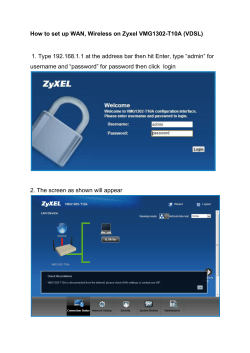


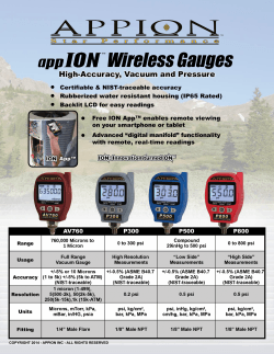

© Copyright 2026