
The Blackbird 2M Project, Part 1
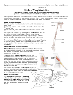
On the ’Wing... #143
The Blackbird 2M Project, Part 1
After more than twenty years of building tailless sailplanes, we’ve come to the conclusion that the
greatest “bang for the buck” is the Blackbird 2M, a Dave Jones design, once available through his
Western Plan Service.
In all, we’ve thus far built six renditions of this design: two of the per plans 2 meter, 78.5" span;
one RC-HLG of 59" span; one foam core version of 90" span (formulated to take advantage of all
winch power); and two XC monsters of 107" span and maximum FAI wing area, 2325 in2.
These aircraft, particularly the original Blackbird 2M, build rapidly, take little in the way of
materials considering their overall size, and are quite maneuverable for both thermal and slope
flying. The low aspect ratio gives a good speed range and a very light wing loading, and they
thermal easily. Because they lack lower surface flaps, landings are done at relatively high speed. If
it were not for this characteristic, the two meter version, built per plans, would make an excellent
contest ’ship in the AMA two meter class!
We have now started building our seventh Blackbird. Some changes are being made to the
structure and to the aerodynamics in light of previous experiences with this design. This month
we’re going to cover all of the various modifications which will be incorporated into the finished
model.
Airfoil
The original Blackbird 2M incorporated the CJ-3309 section. This is an airfoil of 9% thickness
which has 3% camber with a high point at 30% chord. One the advantages of the CJ-3309 is that
the lower surface is flat from just behind the nose radius to 75% chord. This makes construction a
breeze. The CJ-3309 performs well if the model will be used for thermaling, but due to the flat
bottom and relatively severe reflex, it just cannot fly fast. As well, any inertia gained during a
zoom from a winch launch is rapidly dissipated into airfoil drag rather than into terminal height.
Our second Blackbird 2M and both of the XC versions incorporated the CJ-25^209. This airfoil is
a big improvement over the CJ-3309. The thickness remains at 9%, but the camber is reduced to
2.5% and the high point is moved forward to 25% chord. This reduces the needed reflex and the
drag is significantly less as a result. Additionally, this airfoil incorporates what has come to be
called a “Phillips entry,” so the lower surface is flat over a shorter distance - from 25% chord back
to 75% chord. The wing structure can still be built on a flat surface without resorting to complex
jigs, but the result is again less drag.
We became very excited about the BW 05 02 09 section while building the modified Model
Builder Raven, and just could not wait to try it on the Blackbird planform. The BW 05 02 09
section is the work of Barnaby Wainfan, famous for his free flight designs and the full size
“Facetmobile.” This section was originally an option airfoil for the Raven S, the last of the Raven
series. The BW 05 02 09 has just 2% camber with the high point at 30% chord. The lower and
upper surfaces of this section are curved over the entire chord, so the wing structure needs some
sort of jig for proper alignment during construction.
1 of 23
Elevon design and structure
The original Blackbird 2M plans show an elevon with a Frise-type structure. That is, the hinge
point is some distance behind the leading edge of the surface, and as the surface is deflected
upward the leading edge protrudes from the bottom surface. The upper surface remains smooth
regardless of deflection.
There are two difficulties with this control surface. First, it causes drag any time the surface is
deflected upward. The idea behind the design is to control adverse yaw when applying aileron.
However, the additional drag created when applying up elevator is substantial and unnecessary.
Second, we’ve found that rather than reducing adverse yaw, the Frise-type elevon design causes so
much drag that proverse yaw appears.
In flight, these two difficulties are immensely evident. When the transmitter stick is moved to roll
the aircraft to the right, the Blackbird does not roll at all. It does, however, yaw to the right. In
fact, if you move the aileron stick from right to left and back again, the Blackbird will swing
somewhat violently in yaw, with no rolling motion in evidence. The glide ratio is of course much
worse under this condition. Additionally, the added drag of two protruding surfaces in the lower
surface airflow grossly affects aircraft performance during up trim conditions and when applying
up elevator in a thermal turn.
Our first modification to eliminate the Frise-type surface included use of a MonoKote hinge at the
upper leading edge of a conventional angled leading edge elevon. This change very much
improved performance. Proverse yaw is still noticeable, but it is certainly not so severe as before,
and there is no protruding surface when up elevator is applied. Blackbird #7 will use a MonoKote
hinge on the lower surface, as the 90” span version successfully employed. We’ll explain the
improved elevon structure in more detail in another installment.
Spar structure and wing rods
The per plans spar structure consists of an upper and lower cap of 3/8" by 1/8" spruce with
vertical grain balsa webbing. We’ve always modified the caps so they taper from 1/2" by 1/8" at
the root to 1/4" by 1/8" at the tip.
Both wing rods are specified on the plans as being 3/16" diameter. We’ve always increased the
forward rod to the next larger diameter music wire, 7/32".
The resulting spar and wing rod combination, along with the very thick wing root and limited
span, makes full power winch launches not only possible, but a true joy. The zoom off the launch
always gets ooohs and aaahs from the modeler audience, and is quite astounding considering the
wing is nothing more than the standard D-tube and open bay structure.
Servo placement
Our first Blackbird 2M utilized NyRods to connect the servos, mounted in the fuselage, to the
elevons. Due to the 90 degree bend in the conduit, there was a lot of play in the system which
could not be removed. The elevon centering was always dependent upon which way the servo had
last moved. Additionally, the servo arm could rotate without moving the control surface at all.
Subsequent Blackbird construction projects, independent of size, have the servos placed in the
2 of 23
3 of 23
wing area = 1256 sq. in., weight = 43 to 70 ounces
wing loading 5 to 8 oz./sq ft., aspect ratio = 4.9
- fuselage sides 1/8" plywood, fuselage width = 2.5"
- fuselage top and bottom are 1/8" balsa, except for
1/4" plywood bottom from rear of main spar forward,
second layer of plywood for bottom front 5" of
fuselage, last three inches of nose consists of layers
of 1/4" inch plywood with lead slug insert to roughly
position the CG in the correct position
- front 8" of fuselage has 1/4" balsa side doublers to
allow rounding of nose
- CG is 7.5" to 8" behind leading edge at root, towhook
is 1/8" in front of CG
control horn location
elevon 11.25" x 4.5",
1/4" internal ribs,
1/32" sheeting,
finger hole
bottom hinging
- all sheeting and cap strips are of 1/16" balsa
- cap strips are 1/2" wide
- wing leading edge 1/2" x 3/4" balsa
- 1/64" plywood at trailing edge of wing and fin
- wing tips have a core of 1/16" plywood glued to
inner side of lower sheeting
- wing rods are 7/32" music wire front, 3/16" rear
- enclosed finger holes at root of each wing near CG,
bottom sheeting is 1/16" plywood in this area
- front wing rod at 6.25" behind wing root leading
edge, rear wing rod is 9.75" behind leading edge
Dave Jones, Torrance CA, 1983
BLACKBIRD 2M
- upper fin is 1/16" balsa sheet over 1/8" ribs, lower fin is 1/2" light balsa
sheet sides over 1/8" plywood keel, upper fin root chord = 13", lower fin root
chord = 14.75", upper fin tip chord = 4.5", fin leading edge sweep = 14"
- rib spacing: 1 (root) to 2 = 5" , 2 to 3 = 6" , 3 to 4 = 6",
4 to 5 = 6" , 5 to 6 + 6" , 6 to 7 = 5.5"
- wing tip span = 3.5"
- section lengths: 1 = 19.75" , 2 = 18.75" , 3 = 17.5" ,
4 = 16.375" , 5 = 15.125" , 6 = 13.875" , 7 = 12.75"
servo
all ribs of 1/8 balsa
- spar caps are 1/2" x 1/8" spruce, tapering to 1/4" x 1/8" at wing tip.
- 1/16" plywood spar faces through first and second bays, then 1/8"
vertical grain balsa web in bay 3 and 1/16" vertical grain balsa webbing
through bays 4, 5, and 6
wing with direct straight connections to the elevon control horn. The Blackbird described in this
article will utilize Volz WingMaxx servos mounted near the inner edge of the elevon.
And in future installments you’ll find...
As we write this column we’re already well into construction of Blackbird #7 and have the
fuselage completed. The wings require the upper sheeting of the D-tube and cap strips, plus the
usual sanding of the leading and trailing edges, etc. We’re planning to have the model completed
by the time you read this column.
Next month’s column will provide information on the BW 05 02 09 airfoil which we’ll be using
on this rendition.
The third installment will include construction hints based on our previous experiences with this
design, photos of the building process, drawings of the various specialty parts which will be
needed, and other items which RCSD readers should find both interesting and motivating.
Test flying will of course depend on weather, so any delays in the printing of the final installment
will not be our fault!
Comments, questions, and suggestions for future columns may be sent to us at either P.O. Box
975, Olalla WA 98359-0975, or <[email protected]>.
_______________
Resources:
Jones, Dave. Blackbird 2M (full size construction plans). Western Plan Service, 1983. (We are not
aware of a retail source for these plans at the present time.)
Kuhlman, Bill & Bunny. Goliath. RCSD, February 1988.
—. Notes on “planks.” RCSD, October 1989.
—. Suggestions for first ’wings - part II. RCSD, March 1991.
—. How “planks” fly. RCSD, March 1992.
—. Aileron differential: some possible effects on performance. RCSD, August 1992.
—. A possible solution to adverse yaw in plank planforms. RCSD, May 1996.
—. Modifying and building the MB Raven. RCSD, June through September 1999.
4 of 23
On the ’Wing... #144
The Blackbird 2M Project, Part 2
As we mentioned in Part 1, we’ve decided to use Barnaby Wainfan’s BW 05 02 09 section on this
rendition of Dave Jones’ Blackbird 2M. This is the same airfoil which we used on our modified
Model Builder Raven project last year.
The BW 05 02 09 first came to our attention through the Raven S, another Dave Jones design. It
was noted on the plans as an alternative to the CJ-25209 section used on the prototype. Rib
templates for both the CJ-25209 and BW 05 02 09 airfoils were provided on the full size plans.
Not having coordinates for the BW 05 02 09, we contacted Barnaby Wainfan. Barnaby reported
that he did not have coordinates for the section in his files.
We have several plotting programs on our Macintosh computers. One of these, Foil 1.2, has the
capability of deriving coordinates from scanned images. The plywood wing end cap was scanned
at 300 dpi, and the resulting black and white TIFF image was then modified to remove any
extraneous dots and lines. The clean image was imported into Foil 1.2 and the coordinates derived
using the software code.
With the coordinate table in hand, we opened up Dave Johnson’s MacFoil and had our printer plot
out the airfoil using the end cap chord. Using a light table, we gradually adjusted the coordinates
until the plotted section exactly matched that shown on the plans. The resulting coordinate table,
as presented here, was forwarded to Barnaby to add to his archives.
While writing this article, we were visited by Andy and Alison MacDonald. Andy runs a web site
devoted to flying wings, and he and Alison have spent the last three months traveling around the
United States. Andy had his laptop and a copy of Eric Sanders’ Compufoil. Compufoil quickly
provided the BW 05 02 09 pitching moment (+0.018) and zero lift angle (-0.15°). As this section
was designed for non-swept, i.e. “plank,” wings, the zero lift angle is not of immense importance.
The pitching moment, on the other hand, provides the information required to determine the
amount of pitch stability. Most of the later CJ sections had pitching moments around 0.03 to 0.04,
so the BW 05 02 09 is a bit less stable. The last airfoil Dave Jones produced was the CJ-21509
(1.5% camber, 9.5% thickness), which had a pitching moment of 0.0145 and a zero lift angle of
-0.1196°. In looking at airfoils designed for planks, the general trend is toward lower positive
pitching moment values. Less reflex equates to lower drag, a more rearward CG range, and better
performance.
The one disadvantage of the BW 05 02 09, when compared to Dave Jones’ CJ series, is its lack of
a flat spot on the lower surface. The CJ-3309 lower surface is flat from about 2.5% chord back to
75% chord; the CJ-25209 lower surface is flat from 25% chord to 75% chord. This flat spot allows
easy construction, with a minimum number of jigs, etc., on just about any flat surface. Since the
Blackbird 2M wing uses a D-tube leading edge and relatively open bay construction aft of the
main spar, the BW 050 02 09 forces the builder to use jig blacks or some other method of
maintaining alignment.
MacFoil, once a few distances and/or percentages are noted in various parameter “fill-ins,” easily
plots full size templates with sheeting and spar locations drawn in. Rib patterns can be easily cut
5 of 23
BW 05 02 09.coord
1.00000 0.00000
0.95000 0.0045
0.90000 0.00813
0.80000 0.01833
0.70000 0.02937
0.60000 0.04157
0.50000 0.05337
0.40000 0.06236
0.30000 0.0665
0.25000 0.065
0.20000 0.061
0.15000 0.0555
0.10000 0.0460
0.07500 0.0395
0.05000 0.0315
0.02500 0.02125
0.01250 0.01425
0.00750 0.01035
0.00375 0.0065
0.00200 0.0045
0.00100 0.00285
0.00010 0.00155
0.00000 0.00000
0.00010 -0.00050
0.00100 -0.0015
0.00200 -0.0025
0.00375 -0.00375
0.00750 -0.0055
0.01250 -0.00725
0.02500 -0.0105
0.05000 -0.0145
0.07500 -0.01725
0.10000 -0.01945
0.15000 -0.02231
0.20000 -0.02350
0.25000 -0.02477
0.30000 -0.02547
0.40000 -0.02655
0.50000 -0.02755
0.60000 -0.02699
0.70000 -0.02576
0.80000 -0.02184
0.90000 -0.014
0.95000 -0.00777
1.00000 0.00000
6 of 23
from sheet aluminum flashing material using scissors. The important item here, however, is the
ease with which templates for contoured jig blocks can be cut out by using the sheeting contour
and section base lines.
During construction, all of the lower surface sheeting is assembled over the plans, followed by the
main spar. The ribs are then glued to the lower portion of the D-tube and the cap strips with
medium CA glue and a metal ruler. The metal ruler is slid under the cap strip and used to apply
upward pressure to the cap strip and rib assembly while the glue cures. Once the glue has set, the
contour blocks are slid between the cap strips and the building surface and the D-tube and the
building surface. Nearly all of the remaining wing construction can be completed with the blocks
in place.
Comments, questions, and suggestions for future columns may be sent to us at either P.O. Box
975, Olalla WA 98359-0975, or <[email protected]>.
_______________
Resources:
Compufoil. Eric Sanders. 2000. <http://www.compufoil.com>
Foil 1.2. Gregory Payne. 1994. (Gregory is no maintaining a Foil 1.2 web site, but we can provide
the complete Foil 1.2 package as an e-mail attachment to those requesting it. Foil 1.2 is free, but
not public domain.)
MacFoil. Dave Johnson. 1998. (Available through Dave’s MacFoil web site,
<http://www.sirius.com/~djohnson/macfoil.html>.
Jones, Dave. Blackbird 2M (full size construction plans). Western Plan Service, 1983. (We are not
aware of a retail source for these plans at the present time.)
Kuhlman, Bill & Bunny. Modifying and building the MB Raven. RCSD, June through September
1999.
7 of 23
On the ’Wing... #145
The Blackbird 2M Project, Part 3
This month we tackle the construction portion of our Blackbird 2M #7 project. With only four
major components, the Blackbird builds fast. Besides outlining the basic construction process,
we’re including some building tips which might be found useful. Additionally, we describe a
method for fabricating an aerodynamically clean control surface actuating system which uses off
the shelf parts and simple construction.
____________________
The first construction task consisted of making all of the required templates. We use the aluminum
sheeting sold in hardware stores as roof flashing material. Thirty-one templates were made in all:
fuselage side and front and rear fuselage jig blocks, seven wing ribs and 14 wing jig blocks, one
elevon rib and four fin ribs, and the main wing tip and inner plywood stiffener outlines. The
complete template set can be seen in Photo 1. Driving a fine nail through the template while it’s
supported by a wooden block will create a punctured dimple on the back side. A couple of these
are very effective at giving the template some purchase on balsa, preventing movement during
cutting.
Photo 1
8 of 23
Photo 2
Fuselage
Because the fuselage must accurately mate with both the wings and the fin, we started actual
construction with it. The fuselage shape is a derivation of the wing section, so it is somewhat
different from that shown on the plans. Using the fuselage side template, we cut the sides from
1/8" plywood. The two sides were tacked together with rubber cement and the holes for the wing
rods and the servo cable conduits were then drilled out with a drill press.
Using steel machinist blocks and metal triangles, and working on a glass surface, the fuselage
sides were set upright on the pre-cut lower sheeting and tacked in place. The jig blocks were then
placed beneath the trailing edge and the gluing completed, followed by placing the two brass wing
rod tubes and constructing their associated spar joiner assemblies. With these items firmly in
place, the laminated plywood nose block was cut to a flat sided shape with a table saw and glued
into place.
Once all of the internal structure is complete, the 1/8" balsa sheeting can be affixed to the top of
the fuselage, along with the hatch cover which is tacked in place with a few small drops of CA.
Don’t forget to include some sort of base for the towhook. Photo 2 shows an opening contoured
for an Airtronics adjustable towhook.
We used a coarse rasp to get the front of the fuselage into its rough shape. Laminated plywood is
very difficult to contour with sandpaper alone. Two PermaGrit sanding blocks — one coarse, one
fine — were then used to obtain the final finish and prepare for the fiberglass skin. The results of
our handiwork are depicted in Photo 3. You may want to wait until the fin is completed before
finishing the fuselage with ’glass. We find it best to integrate the fin assembly and fuselage and
9 of 23
Photo 3
then ’glass and paint as a unit. The fiberglassing process will be covered in the fourth installment
of this series.
Fin and sub-fin
The fin is essentially a hollow block consisting of 1/16" balsa sheeting, a strip of 1/64" plywood to
strengthen the trailing edge, four ribs, a tip piece, and a spruce leading edge. The completed fin
and sub-fin assembly can be seen in Photo 4. Several builders have commented that a substantial
weight saving can be had by using 1/32" sheeting in lieu of the 1/16" shown. Don’t try this unless
you use a foam core.
Construction is somewhat tedious when using the conventional rib structure, as balsa trailing edge
stock must be used as an assembly jig to prevent any twist from being built in. Once set up,
however, construction is rapid. Using a foam core may be an easier and more comfortable route
for some builders.
The two skins are cut out using the plan outline and the fuselage template, and the right side is
internally marked for rib placement. The trailing edges of both skins are sanded to a fine angle to
make room for the 1/64" plywood strip and the strip is glued on to the right side. The right side is
then placed in the jig and the ribs are glued in. We’ve found it to be somewhat helpful to wet the
outside of the sheeting in the area of the leading edge so it more easily conforms to the ribs in that
area. The left side sheeting is glued on, taking special care to keep the trailing edge straight. Once
the left side is glued on, any twist which is built in will be permanent. The leading edge and tip
piece can be glued on with the fin removed from the jig.
10 of 23
Photo 4
Make sure you use a light touch when sanding the fin, as it’s very easy to sand waves and
depressions into the skin, making it too thin.
The sub fin is hollow as well, built with an interior plywood core and light balsa “cheeks.” We
laminated several balsa sheets together for each of the two sides so that we could use the seam
lines as guides during the shaping process. Use the fuselage template to get the sub fin contour to
perfectly match the rear of the fuselage. The plywood core is cut out to the proper contour and
placed on a sheet of glass. One side piece is then glued to it and the assembly is inverted after the
glue has hardened. The other side piece is then added.
Carefully match the joint the joint between the fin and sub fin so the completed assembly fits the
fuselage as closely as possible, then glue the two parts together. Now shape the sub fin so it
matches the airfoil shape of the fin at the glue joint. Shaping this part is a breeze, as the balsa
sands easily.
The fin can be covered with MonoKote®, but we’ve had great success with well sanded gray
primer and a light coat of paint. The sub-fin deserves a layer of 1.2 ounce fiberglass. It’s easy to
mate the fin assembly to the fuselage and then do all of the fuselage ’glassing, sanding, and
painting in one fell swoop. But don’t mate the fin assembly to the fuselage just yet. As mentioned
earlier, we’ll tackle this part of the construction process in Part 4.
Wings — getting started
Preliminary construction of the wing is accomplished on a large piece of ceiling tile. The plans are
attached to this building surface and covered with overlapping sheets of waxed paper.
11 of 23
All of the bottom sheeting and cap strips are cut to shape and glued together right on the plans,
and the lower spar cap is then glued in place. The ribs are tacked in place by applying glue to the
flattest portion of the bottom of the rib with a steel block against the side to assure exact vertical
alignment. With everything in place, use the leading and trailing edge jig blocks to get the
sheeting into contact with the bottom of each rib. A thin metal ruler can also be used to leverage
the sheeting against the rib. Glue by using the CA wicking action. Photo 5 shows the wing at this
stage of completion.
Photo 5
The servo mounts should now be framed in. Rolled paper tubes can be used for servo cable
conduits, and a string of drinking straws for the antenna routing. We made the paper tubes rather
quickly by wrapping bond paper around a long 3/8" aluminum tube and using a common glue
stick. Two layers is sufficient. The end of one of these tubes can be seen in Photo 6. Make sure all
of the conduits exit the wing root so they line up with the pre-drilled holes in the fuselage sides.
We got both wings to this point and set them aside. Construction can continue without the plans
being under the structure, and you want to work on glass or some other stable surface for the
remainder. In the meantime, you’ll need access to the wing panels with the servo locations known,
to assist in building the elevons.
Elevons
The elevons are constructed in a fashion similar to the fin. Set up the jig blocks first and mark the
elevon bottom skin for the rib positions. The elevons on our model are somewhat different than
those shown on the plans. The Blackbird 2M plans show a Frise-type elevon, incorporated to
12 of 23
Photo 6
overcome adverse yaw. See the included line drawing. We have always found this control system
to produce an extreme amount of proverse yaw and unnecessary drag when up elevator is applied,
in addition to having a complex hinging method. We very much prefer bottom hinging using
MonoKote® as the hinge material.
One of the more exciting things we’ve done on this model is to completely bury the control horn
and pushrod assembly inside the wing and elevon. See the line drawing again and also Photo 7.
This is possible because the rear of the wing section is relatively thick. (If, in some other
application, hinging is at the top, the control horn can simply be inverted and affixed to the upper
surface.)
With the bottom skin in the jig, glue on the leading edge, then the ribs. Depending on the eventual
servo mount location, determine where the control horn should be. A 1/32" plywood control horn
base is first put in place and the control horn attached to it. We mounted the control horn to the
plywood base by roughing up the bottom surface of the horn and applying CA glue. Once set, we
took a small square of fiberglass cloth, slit for the horn to protrude, and used it to cover the base of
the horn and the surrounding plywood. The ’glass was firmly attached to the horn and the
underlying plywood with CA. With all of the internal structure complete, and the elevon still in
the jig, glue on the upper sheeting.
Temporarily attach the completed elevon to the wing using masking tape as the hinge. The end of
the control horn and the pushrod opening can be seen in Photo 8.
13 of 23
Photo 7
Photo 8
14 of 23
Photo 9
Wings — completing construction
With both wings nearly half complete, set up the fuselage on a large glass surface and weight it
down with all of the jig blacks fore and aft. Insert the wing rods so they protrude from both sides
and slide the wing rod receptacles onto them. Slide the wings against the fuselage at the proper
location with the wing rod receptacles extending into the wing. Block up the wings at the proper
dihedral angle by inserting balsa strips under the ribs — 1/8" under the first rib, 1/4" under the
second. Slide in the leading and trailing edge jig blocks and weight the wings so they won’t move.
The setup should look like what is shown in Photo 9. Make sure the fuselage and wing roots are in
contact with the glass at matching points.
With the wings held in the correct location along the fuselage and blocked at the correct angle,
install all of the shear webbing in the area of the wing rods using CA and epoxy as necessary. The
rear spar assembly is complete in Photo 10. Working carefully, the wing rod receptacles will be
perfectly aligned with the fuselage assembly.
Once all of the internal structure is complete, attach the upper surface leading edge sheeting, root
sheeting, and cap strips. The leading edge sheeting works around the ribs a bit easier if the outer
surface is dampened.
The last step is to add the leading edge and form it to the correct shape. We use a heavy duty razor
plane to get things started, then it’s back to the PermaGrit blocks for getting the shape just right.
Putting the three major components together
The entire airframe is now complete. The fin and sub-fin assembly should slide onto the fuselage
with a slightly snug fit. Make sure the fin is perfectly aligned on the fuselage centerline before you
15 of 23
Photo 10
Photo 11
16 of 23
permanently attach it. The wings will mount on the wing rods and exactly match the fuselage
contour from the wing section high point rearward. The receiver and battery pack fit easily in the
front of the fuselage. Trace the antenna through the drinking straws and hook up the two servos by
simply plugging them in. On the field, the only additional task is taping the wing-fuselage joints.
Photo 11 shows the completed Blackbird 2M airframe, ready for ’glassing, painting, and
covering.
The next installment will include fiberglassing, covering and painting, gap seals, and our first trip
out to the flying field. Stay tuned! (And join with us in hoping for good weather.)
Comments, questions, and suggestions for future columns may be sent to us at either P.O. Box
975, Olalla WA 98359-0975, or <[email protected]>.
Resources:
Jones, Dave. Blackbird 2M (full size construction plans). Western Plan Service, 1983. (We are not
aware of a retail source for these plans at the present time.)
Kuhlman, Bill & Bunny. Goliath. RCSD, February 1988.
—. Suggestions for first ’wings - part II. RCSD, March 1991.
—. Aileron differential: some possible effects on performance. RCSD, August 1992.
—. A possible solution to adverse yaw in plank planforms. RCSD, May 1996.
17 of 23
On the ’Wing... #146
The Blackbird 2M Project, Part 4
Well, our own personal schedules and the weather finally coincided, and our newest Blackbird 2M
has been finished and test flown!
At the end of the last installment, the fuselage was yet to be fiberglassed, the wings needed to be
covered, and all of the bare wood and fiberglassed surfaces were unpainted. We’ll cover these
items one topic at a time.
Fiberglassing the fuselage
Two weights of fiberglass were used, 1.5 ounce and three ounce cloth. Rather than use epoxy
resin, we used the polyester type. We don’t like to use epoxy resin when ’glassing a fuselage, as
it’s more expensive, takes longer to cure, is tricky to sand, and is not any more resistant to damage
in this environment.
Our first task involved making a fiberglass cloth fillet along the line where the fin and sub fin meet
the fuselage. Narrow strips of three ounce cloth, cut on the bias, were tacked in place with CA
glue, and a stiff resin brush was used to apply the resin and obtain a reasonably smooth surface.
The sub fin and the lower portion of the fuselage nose back to the tow hook location were covered
with the heavier cloth, as those surfaces get a lot of abuse. The remainder of the fuselage, with the
exception of the wing root areas, was then covered with the lighter cloth.
Flexible foam backed sandpaper and PermaGrit flats were used to eliminate excess resin and glass
“flashing,” and obtain a smooth surface for painting.
Covering the wing
We really like to have the upper surface of our aircraft a light color, and the bottom surface a dark
color. From below, the pilot sees a dark object which is in contrast to the sky and clouds. When at
distance, the light surface is visible as the aircraft turns toward the pilot, the dark surface as it
turns away. While some trim coloring is OK, you don’t want to overdo it, as the color desired
contrast is easily lost.
On our second Blackbird, we used fluorescent yellow for the upper surface, and black for the
lower. Pinstriping of the contrary color was then applied in a random pattern. Very simple to
apply, somewhat complex in appearance, it has no effect at all on visibility. And we still get lots of
positive comments at the flying field.
Looking through our collection of covering materials, we found more than enough MonoKote
white for the upper surface, but not enough black or similar very dense color for the lower surface.
Digging deeper, we found a roll of Pactra SolarFilm tropic blue. This color is not so dense as we’d
like, but it does suffice. On a more positive note, SolarFilm is applied at a lower temperature than
MonoKote, some interesting color trim possibilities became possible, as we’ll describe shortly.
We challenged our son, Dan-the-artist, to come up with a color scheme using these two colors.
His immediate idea involved spray painting the colored trim onto a white base color. This meant
spraying paint onto MonoKote, however, something we did not want to do. Taking the pinstriping
18 of 23
1"
1/2"
1/4"
1/8"
1/8"
1/4"
1/2"
idea a step further, he suggested making color strips of varying widths and varying the spacing
between the strips. This would give the appearance of blended colors at a distance, as would have
been obtained with spray painting, while appearing as simple striping when viewed at close range.
Additionally, MonoKote would be used as the base, and the low temperature SolarFilm would
then be easily applied over it.
Contrary to usual practice, the upper surface covering was applied first. The covering was
wrapped around both the leading and trailing edges of the wing to eliminate creep. See the
included drawing.
The lower surface of the wing was then covered with tropic blue SolarFilm. The covering was
trimmed at the edge of the trailing edge and wrapped around the leading edge. A 1.25 inch strip of
SolarFilm was then applied at the leading edge such that the aft edge is exactly one inch behind
the leading edge as viewed from above. A half inch strip was then applied one eighth inch distant,
followed by a quarter inch strip at one quarter inch distance, and an eighth inch strip one half inch
distant. See the included color scheme drawing.
The elevons were covered separately and then attached to the wing using strips of MonoKote and
SolarFilm as hinging material.
Painting the fuselage
Zynolyte gray primer was applied to the entire fuselage and sub fin, the fiberglassed areas.
Zynolyte primer is fairly versatile, and can be used under enamel, lacquer, and other types of
paints. Additionally, it can be used to fill pin holes and other slight imperfections.
19 of 23
The entire fuselage, fin and sub-fin assembly was painted with three coats of Zynolyte white
enamel and then masked to match the wing color pattern.
Matching paint colors to covering materials has always been a difficulty. While there are some
specialty paints, such as those mixed to match specific MonoKote colors, we really wondered
about finding a paint to match the SolarFilm tropic blue. Again, Dan to the rescue! He said, “Hey,
I know a guy who runs an automotive paint shop, and he can mix up a spray can to match
anything. Just give me a sample of the covering you want to match, and I’ll get it for you.” So we
cut a triangle of about two square inches from the corner of the sheet, and, sure enough, three days
later he brought a spray can of custom mixed enamel paint. And yes, it’s a perfect match!
Here’s the story on that custom mixed paint. Dan’s friend, Nick Wahlberg, is a part of LDI
Automotive Paints and Equipment in Tacoma, and is a wealth of information when it comes to
automotive paints. The can he provided for our project holds 7.6 ounces of paint and propellant.
Although we used an automotive acrylic enamel, the cans can also be filled with acrylic lacquer or
an industrial oil based paint. If you choose an enamel paint, it can be placed in a can which has a
fitting made for inserting the special enamel hardener. The acrylic enamel can take temperatures
of 350° to 400° and is resistant to a wide variety of solvents. Dyes are also available for tinting
vinyl, plastic, and some metals (interior use only). The acrylic paints give a glossy finish, while
the dye imposes a semigloss or satin finish, depending on the surface. Both the enamel and
lacquer can be flattened a moderate degree, but this makes spraying more difficult. The price per
can is a very reasonable $10.00 - this includes the color matching!
The paint matching process is, like most things these days, almost entirely computerized. Nick did
run into some problems with our sample, as SolarFilm is extremely glossy and, interestingly,
somewhat transparent. The color matching process is very delicate, and Nick found the color
value changed depending on what material was underneath the sample. Although the computer
did an acceptable job of matching, Nick’s fine was eye was the final authority.
The filled spray can is considered to be hazardous material, so shipping or mailing is not possible.
Nick recommends that readers contact their local automotive painting establishments for similar
services, but went on to say that he’d be glad to answer any questions RCSD readers may have.
Contact information is included in the resources section of this column.
Radio installation and CG setup
We installed one Volz WingMaxx servo in each wing, as was planned during construction. These
servos have small ridges on the side of the servo which snap into indentations in the mounting
frame. Two small set screws are used to rigidly connect the servo with the frame. Getting a photo
of the installation was impossible because access is from below and this exposes only the bottom
of the servo. The linkage is not visible from outside the wing. A four cell battery pack was placed
in the front of the fuselage, and the receiver placed behind the single plywood bulkhead. There’s
lots of open area left. Set up the control surfaces for neutral position with the transmitter trims in
neutral.
We found the CG location on the most recent Blackbird and measured the distance to the wing
leading edge at the root. This distance is seven inches. The tow hook on this airplane is 3/8” ahead
of the CG. We’ve found that this location works well. Any further back and the ’ship comes off the
line in the initial stages of the launch because of over rotation. We marked the identical CG
20 of 23
Bill with all three of the two meter Blackbirds. The one in the foreground, “Candide,” was built in
1985, has several hundred flights on the airframe, and is sporting its third covering job. The
fluorescent yellow Blackbird, “Galah,” on the right, was built in 1993 for a trip to Australia. It’s been
recovered once. “Cebu” already had several flights on it when this photo was taken.
— photo by Bob Brewer
21 of 23
location and tow hook placement on the new Blackbird, added a couple ounces of lead in front of
the battery pack to place the CG on the mark, tightened the tow hook, and went out to the field.
Test flying
The initial flights of a tailless aircraft are the most treacherous, as they are quite sensitive to the
CG location. We thought we had this one pretty well pegged from the outset, but with the different
airfoil, questions remained. Bill held the aircraft overhead and ran into the wind, letting the wing
try to lift itself. Any severe pitching can be easily felt this way, in our experience. With nothing
unusual being felt, we proceeded to do the same again, letting the aircraft float ahead on its own
with a gentle additional push. That first hand launch was just short of incredible. A very nice flat
glide with no control input, and a landing spot about 15% further out than our most recent model.
A second hand glide showed the same promise, with good response to elevator and aileron
functions. The airframe was thoroughly checked over at home, and a second trip to the field was
made for the initial winch launch.
A quick hand glide was made, and then it was on the winch line. The first launch was made with
the same power as would be used for a polyhedral floater. This technique resulted in a good
straight tow with a good release from the line. A turn to the right kept it away from the electrics.
The stick was moved straight left and right several times in quick succession while flying straight
overhead with very little proverse yaw in evidence. This is in contrast to others in this series.
There’s still some yawing into the turn before the roll actually starts, but this is certainly an
improvement. Managed to fly into some light lift over the tall grass, and proceeded to circle a few
times with obvious height gain. After some cruising, the ’ship was set up for a cross wind landing,
per our usual practice, with good control maintained throughout. The overall impression is that
this airplane flies noticeably smoother than previous versions, excluding the big XC version. The
reduction in proverse yaw is a welcome change! Additionally, this airplane does not seem to be so
prone to circle tightening during thermal turns.
The second winch launch was an anticlimax. Bill wasn’t thinking about having a new airplane in
his hands, but stepped up to the winch thinking he had the old standby on the line. A lot of line
tension and a strong upward throw had her climbing out at an 80 degree angle. No letup on the
winch pedal, just a smooth transition into the zoom with the winch still putting out uninterrupted
power into the airframe. The zoom turned out to be about 50% higher than that obtained with the
CJ 25209 equipped version, a tribute to the lower drag of the BW 05 02 09 airfoil.
Parameter
Candide
Galah
Cebú
Airfoil
CJ 3309
CJ 25209
BW 05 02 09
JR micro,
fuselage,
GoldenRod cabling
Royal mini,
wing,
direct drive
Volz WingMaxx,
wing,
internal direct drive
Frise type,
1/16” mw axle
MonoKote,
hinge on upper surface
MonoKote/SolarFilm,
hinge on lower surface
Servo type,
location,
connection to elevon
Elevon hinge
22 of 23
The last part of any project is to arrive at some sort of nickname for the completed project. Our
first Blackbird acquired the “Candide” nickname because its first flight was very much like the
music of the same name written by Leonard Bernstein. Our second received the “Galah” moniker
while in Australia. The Australian Galah is a grey-backed, pink-breasted parrot which is both
gregarious and noisy, destructive and silly. For some reason the name seemed appropriate at the
time and has never been changed. The newest model got its nickname from a breed of cattle, “sort
of like a cow,” which has a humped back. Three cartoon Cebú are featured in a “Veggie Tales”
video, and our granddaughter has implanted their song into our household as a permanent fixture.
(“Achoo moo moo,” “Boohoo moo moo,” “Mmm mmm mmm mmm...”)
In all, this project has been an extremely positive experience for us. Although it took a bit longer
than expected to complete, the results of this building project have been and continue to be most
gratifying. We’re eager to hear from RCSD readers who tackle the Blackbird 2M project, and are
happy to answer questions and respond to comments.
Resources:
Jones, Dave. Blackbird 2M (full size construction plans). Western Plan Service, 1983. (We are not
aware of a retail source for these plans at the present time.)
LDI Automotive Paints & Equipment, Inc., 1108 S Center St, Tacoma WA 98405, (253)
383-5747. Contact Nick Wahlberg <[email protected]>.
23 of 23


© Copyright 2026