
Gilson 151/152 UV/VIS Detectors User`s Guide
Gilson 151/152
UV/VIS Detectors
User’s Guide
LT1033/©2004 Gilson, Inc. All rights reserved
March 2004
Table of Contents
Declaration of Conformity
1 Introduction
Description ............................................................................ 1-1
Optics .............................................................................. 1-2
Display ............................................................................ 1-2
Features ........................................................................... 1-2
Unpacking ............................................................................. 1-3
Customer Service ................................................................. 1-4
Technical Specifications ..................................................... 1-5
Modes and Their Parameters ............................................ 1-9
Operation Mode ............................................................ 1-9
Status Mode .................................................................... 1-9
Setup Mode .................................................................... 1-9
File Mode ........................................................................ 1-9
2 Installation
Operating Environment ..................................................... 2-1
Temperature ................................................................... 2-1
Contaminants ................................................................ 2-1
Ventilation ...................................................................... 2-1
Condensation ................................................................. 2-1
Electrical Setup ..................................................................... 2-2
Rear Panel Diagram ..................................................... 2-3
Essential Setup ............................................................... 2-4
Optional Connections .................................................. 2-6
Unit ID and Baud Rate Selection ............................... 2-9
Unit ID ............................................................................ 2-9
Baud Rate ....................................................................... 2-10
Plumbing Setup .................................................................... 2-11
Inlet Tubing .................................................................... 2-11
Outlet Tubing ................................................................. 2-12
3 Operation
Operation Flowchart ........................................................... 3-2
Front Panel Diagram ........................................................... 3-4
Software Structure .............................................................. 3-6
Mode Selection ............................................................... 3-6
Parameter List ................................................................ 3-6
Start Up ................................................................................. 3-11
Wake-Up Displays ........................................................ 3-11
Selecting the Mode ........................................................ 3-13
Error Messages ............................................................... 3-14
Detector Setup Parameters ................................................ 3-15
First Display For Setup Mode ..................................... 3-15
Second Display For Setup Mode ................................ 3-16
Third Display For Setup Mode ................................... 3-17
Fourth Display For Setup Mode ................................. 3-18
Operation Mode ................................................................... 3-19
Display For Operation Mode ...................................... 3-19
Output Channels ........................................................... 3-20
Example Run .................................................................. 3-21
Programming the Detector ................................................ 3-23
Remote Event ................................................................. 3-24
Remote Zero ................................................................... 3-24
Programming Tools ...................................................... 3-25
Example 1: Startup File ................................................ 3-26
Example 2: Programmed Run .................................... 3-29
Example 3: Linking to Another File ........................... 3-36
Mobile Phase Tips ................................................................ 3-37
Degas Solvents and Buffers ......................................... 3-37
Check UV and Visible Absorbance of Solvents ....... 3-37
4 Maintenance
Flow Cell Maintenance ....................................................... 4-2
Cleaning the Inside of the Flow Cell (Analytical,
Preparative, Microbore, and SFC only) .................... 4-2
Unclogging the Flow Cell ............................................ 4-5
Replacing Tubing and/or the Flow Cell ................... 4-5
Lamp Maintenance ............................................................. 4-22
UV Lamp Maintenance ............................................... 4-22
Visible Lamp Maintenance .......................................... 4-29
Fuse Replacement ................................................................ 4-35
5 Troubleshooting
Troubleshooting ................................................................... 5-2
Detector Not Functioning ............................................ 5-2
A Lamp Fails to Ignite/A Lamp Fails While On ..... 5-2
Status Lights Blinking/Screen Blank or Dark ......... 5-2
Baseline Spikes ............................................................... 5-3
Baseline Noise ................................................................ 5-4
Baseline Drift .................................................................. 5-5
Autozero Out of Range ................................................ 5-6
Out of Range .................................................................. 5-6
Peaks Too Broad ............................................................ 5-7
Decreased Response to Known Sample .................... 5-7
Abnormally High System Pressure ............................ 5-7
Diagnostics ............................................................................ 5-8
Numeric Analyses on the 151 Detector .................... 5-8
Repair and Return Policies ................................................ 5-10
Telephone Numbers ...................................................... 5-10
Before Calling Us ........................................................... 5-10
Warranty Repair ........................................................... 5-10
Non-Warranty Repair .................................................. 5-10
Rebuilt Exchange ........................................................... 5-11
Return Procedure .......................................................... 5-11
Appendix A
Defaults and Limits
Setup Mode ........................................................................... A-1
Operation Mode ................................................................... A-1
Appendix B
Mode-Specific Functions
Mode-Specific Output Channels ...................................... B-1
Mode-Specific Remote Event and
Autozero Functions ............................................................. B-1
Appendix C
Sensitivity
Appendix D
GSIOC Control
GSIOC Commands .............................................................. D-2
FIFO Commands .................................................................. D-2
GSIOC Command List ........................................................ D-2
FIFO Command List ............................................................ D-10
Appendix E
Replacement Parts
Lamp Assemblies ................................................................. E-1
Cell/Accessory Kits ............................................................. E-1
Flow Cell Assemblies ........................................................... E-2
Inlet and Outlet Tubing ...................................................... E-2
Miscellaneous ....................................................................... E-4
Appendix F
Display Adjustment
Declaration of Conformity
Application of Council Directives:
89/336/EEC, 73/23/EEC
Standards to which Conformity is Declared:
EN61326, EN61000-3-3, EN61000-3-2, EN61010-1:2001
Manufacturer’s Name ........................................... Gilson, Inc.
Manufacturer’s Address ....................................... 3000 W. Beltline Highway
Middleton, WI 53562
EC Office Address .................................................. Gilson S.A.S.
19 Avenue des Entrepreneurs, B.P. 145
F-95400 Villiers-le-Bel, France
Type of Equipment ................................................. Laboratory Equipment
Model. ....................................................................... 151 UV/VIS Detector
Beginning with Serial Number: 109F8E001
Month and Year of Manufacture: June 1998
I, the undersigned, hereby declare that the equipment
specified above conforms to the above Directives and Standards.
Place: Middleton, WI (USA)
Issue Date: August 1998
Michael Jacquart
Senior Vice President
Corporate Technology Development
Declaration of Conformity
Application of Council Directives:
89/336/EEC, 73/23/EEC
Standards to which Conformity is Declared:
EN61326, EN61000-3-3, EN61000-3-2, EN61010-1:2001
Manufacturer’s Name ........................................... Gilson, Inc.
Manufacturer’s Address ....................................... 3000 W. Beltline Highway
Middleton, WI 53562
EC Office Address .................................................. Gilson S.A.S.
19 Avenue des Entrepreneurs, B.P. 145
F-95400 Villiers-le-Bel, France
Type of Equipment ................................................. Laboratory Equipment
Model. ....................................................................... 152 UV/VIS Detector
Beginning with Serial Number: 109A9F001
Month and Year of Manufacture: January 1999
I, the undersigned, hereby declare that the equipment
specified above conforms to the above Directives and Standards.
Place: Middleton, WI (USA)
Issue Date: January 1999
Michael Jacquart
Senior Vice President
Corporate Technology Development
1
Introduction
Description
The Gilson 151 and 152 UV/VIS Detectors are microprocessor-controlled absorbance
detectors that provide single wavelength detection. Both detector models are compatible
components of a Gilson modular HPLC system. And, the 151 Detector with its front panel
control is also compatible with other commercially available HPLC systems.
The 151 Detector can be controlled via its front panel or via external software, such as
Gilson UniPoint™ System Software. The 152 Detector must be controlled via external
software since it does not have an integral front panel display. For information on how to
control the 152 Detector, refer to the user’s guide for the controlling software.
Gilson 151 UV/VIS Detector
1-1
1
Description
Introduction
Optics
Gilson’s optical design lets you monitor absorbance
at any wavelength from 190 to 700 nm.
The detector has a sensitivity range of 0.001 to 2.0
AUFS (Absorbance Units, Full Scale).
Display
Gilson designed the 151 Detector software to be
completely self-guiding.
All parameters, values and commands appear on
the 4-line display.
All of your options are displayed above the six soft
keys. Press a soft key to choose and carry out a
command. Numeric entries are made using the
keypad.
Features
You can choose from the following modes to
specify detection conditions and basic operating
parameters:
•
•
•
•
1-2
operation
file
setup
status
Introduction
1
Unpacking
Unpacking
Unpack the detector and its accessories carefully
from the carton.
Open the detector door and remove the foam insert
from inside the detector.
Cross-check the contents against the checklist
below and against your packing slip, to verify that
all parts are included and undamaged. Do this now,
even if the detector will not be used immediately.
Many carriers must receive concealed damage
claims within seven days of delivery.
The detector is shipped with its flow cell, lamps,
and inlet/outlet tubing already installed. The
carton should also contain:
•
•
•
•
•
power cords
fuse drawers and fuses
two Pomona recorder cables
autozero/event cable
GSIOC cable
Note: The three black-headed shipping screws in
the bottom of the instrument that secure the optical
assembly during shipment must be removed from
the bottom of the instrument before you use the
detector. Save these screws in case you need to ship
the unit.
1-3
1
Customer Service
Introduction
Customer Service
Gilson, Inc., and its worldwide network of authorized
representatives provide customers with these types
of assistance: sales, technical, applications, and
instrument repair.
If you need assistance and are in the United
States, contact your Gilson representative or call
the Gilson Customer Service Department, toll-free
at 800-445-7661 or call 608-836-1551. You may
also contact the Gilson Customer Service Department
via its e-mail address: [email protected].
Outside the United States, contact your Gilson
representative if you need assistance. For more
specific contact information, refer to the Gilson web
site at www.gilson.com.
To help us serve you quickly and efficiently, please
refer to the Before Calling Us section page 5-10.
1-4
Introduction
1
Technical Specifications
Technical Specifications
Warning! Changes or modifications to this device
not expressly approved by Gilson could void the
warranty.
This device has been tested and found to comply
with the limits for a Class A digital device,
pursuant to Part 15 of the FCC commercial
environment. This device generates, uses, and can
radiate radio frequency energy and, if not installed
and used in accordance with the instructions, may
cause harmful interference to radio communications.
Operation of this device in residential area is likely
to cause harmful interference; in which case, you
must correct the interference at your own expense.
You must use shielded cables with this device to
ensure compliance with the Class A FCC limits.
Note: The noise, drift, and sensitivities listed on the
following pages are maximums. Under most
circumstances, you can expect performance that
surpasses these specified limits.
1-5
Technical Specifications
Introduction
1-6
1
1
Introduction
Technical Specifications
1-7
Technical Specifications
Introduction
1-8
1
Introduction
1
Modes and Their Parameters
Modes and Their Parameters
The available modes and their parameters are
described below.
Operation Mode
Wavelength, Sensitivity 1, Sensitivity 2, Peak width
Status Mode
UV lamp status, UV lamp hours, Visible lamp status,
Visible lamp hours, Wavelength, Event input
Setup Mode
Channel 1 scale and offset, Channel 2 scale and
offset, Channel 3 scale and offset, Lamp alarm,
Event channel(s), Autorange channel(s), Autorange
multiplier, Concentration factor, Lamp saver
File Mode
With file mode, you can store as many as ten
program files to save time and to enhance the
reproducibility of your assays. A program file
instructs the detector to change the detection
conditions and to modify the detection
parameters at specified times during the run.
1-9
Installation
2
Operating Environment
You can use the detector in normal laboratory and cold room environments.
The factors described below will influence the performance of your detector.
Temperature
Changes in ambient temperature can produce noticeable output variations, especially at
higher sensitivities.
Avoid areas which are in direct sunlight for part of the day and those which are subject
to draft; for example, do not place the detector near an open window or doorway.
Contaminants
Smoke, vapors, and acid fumes can cause baseline drift and noise.
Ventilation
You must allow at least 4 inches (10 cm) of clearance behind the detector to permit
exhaust from the cooling fan to escape. Also, do not block the ventilation holes on the
bottom of the detector.
Condensation
The detector has two power controls:
•
•
the front panel LAMP ON/OFF key
the rear panel MAINS switch
To prevent condensation on optical surfaces, always leave the MAINS switch ON.
Turn the detector on and off using the LAMP ON/OFF switch.
2-1
2
Electrical Setup
Installation
Electrical Setup
Carefully follow instructions from start to finish.
Electrical connections are clearly marked on the
detector’s rear panel.
You must complete these essential setup steps:
•
•
•
•
insert fuse(s) and fuse drawer
connect output channels to other devices
connect power cord
turn on power
You can also make these optional connections:
•
•
bidirectional communication with a Gilson
system controller on the Gilson Serial Input/
Output Channel (GSIOC)
remote contact control functions
The essential and optional setups are described in
detail on the following pages.
2-2
2
Installation
Electrical Setup
Rear Panel Diagram
1
fuse drawer
Contains the fuses. If it’s not already installed, see page 2-4.
2
MAINS power switch
Use this rocker switch to apply power to the detector. Once
the detector is powered on, leave power on to the detector
unless you are performing maintenance procedures. When
the detector is not in use, press the front panel LAMP ON/OFF
key to turn off power to the lamps instead of turning power off
to the detector.
3
power receptacle
For connecting the power cord to the detector.
4
remote event/autozero For remote activation of some detector functions.
5
output channels
For sending 3 channels of analog data to a recorder or standalone integrator.
6
SW1 selector
For reviewing and changing the unit ID.
7
SW2 selector
For reviewing and changing the baud rate.
8
GSIOC
Gilson Serial Input/Output Channel, a 2-way communications
link to a system controller.
9
RS-232
Serial connector, a 2-way communications link to a system
controller.
2-3
2
Electrical Setup
Installation
Essential Setup
Fuse installation
If you received the detector without the fuse drawer
and fuses installed:
1
Locate the accessory package containing the
fuse drawer appropriate for your line voltage.
Discard the other fuse drawer.
2
Locate the accessory package containing the 2.5
amp fuses.
3
Install the fuse(s) into the fuse drawer. The fuse
drawer for 90–120V accepts one fuse. The fuse
drawer for 220–240V accepts two fuses.
4
Insert the fuse drawer into its receptacle in the
detector. See the rear panel diagram on page 2-3.
Output connections
Note: If the detector is part of a Gilson HPLC system,
you do not need to make output connections. Instead
make the GSIOC connection between the detector
and system controller as described in Optional
Connections, page 2-6.
The detector has three output channels. All three
output channels are active. For more detail on the
output channels see Detector Setup Parameters in
Section 3, Operation.
You can direct output from the detector to a chart
recorder or stand-alone integrator.
To connect an output channel, use a 5-foot shielded
Pomona recorder cable from your accessory kit.
One end of the cable has a dual-pronged plug. The
other end has two tinned wires.
Insert the dual-pronged plug into one of the
detector’s output channels. (Insert the prong with
the GND-labeled tab into the black jack and the
adjacent prong into the red jack.)
2-4
Installation
2
Electrical Setup
Connect the black wire to the other device’s “–” or
“low” input. Connect the red wire to the device’s
“+” or “high” input.
If the other device requires a dual-pronged plug, use
a Pomona cable adapter (part number 6374022611)
to make the necessary connections.
To reduce recorder noise, you may need to connect a
ground strap between the recorder’s GND and “–”
input connectors.
Power connection
Locate the appropriate power cord for your line
voltage. Discard the other power cord.
Use the power cord to connect the detector to an
AC power source.
Gilson strongly recommends that you connect the
power cord to the same outlet that powers the
other components in your system (for example,
your computer, printer, and contact device).
Now all essential electrical connections have been
made.
Next, you’ll find descriptions of these optional
connections:
•
•
•
GSIOC connection
RS-232 connection
contact connections
Note: You must connect the GSIOC cable if you use
the detector as a data acquisition device in a Gilson
HPLC system. If you won’t need the optional
connections, proceed with Plumbing Setup on
page 2-11.
2-5
2
Electrical Setup
Installation
Optional Connections
GSIOC connection
If the detector is part of a Gilson HPLC system, the
GSIOC port is used to transfer information between
the detector and computer. The detector, and other
Gilson GSIOC devices, can convert the RS-232
signal levels used by computers to the RS-422/485
signal levels required by the GSIOC and vice versa.
When you connect the Gilson Serial I/O Channel
(GSIOC) between the detector and an HPLC
system controller, you can:
•
•
•
issue detector commands directly from the
controller
send detector data to the controller for analysis
control and change detector setup parameters
For information on making rear panel connections
for Gilson HPLC system devices, see the installation
guide supplied with the Gilson control software.
See Appendix D for a list of commands that can be
issued to the detector via the GSIOC or RS-232
connection.
RS-232 connection
If the detector is not part of an HPLC system
controlled by Gilson software, the RS-232 port can
be used to transfer information between the
detector and a computer.
Be sure your computer is turned off before making
any connections.
To connect your computer to the detector, you need
an RS-232 cable. Obtain a cable with D-connectors
that are appropriate for the detector and your
computer. The detector requires a 25-pin male Dconnector. Refer to the back panel of your computer
or its documentation to determine which type of Dconnector it requires. RS-232 cables are available
from Gilson and your local computer store.
2-6
Installation
2
Electrical Setup
See Appendix D for a list of commands that can be
issued to the detector via the RS-232 or GSIOC
connection.
Contact connections
You can remotely activate some detector functions
(described below) from devices that provide novoltage contact closure switches.
You can make contact connections from:
•
•
•
•
Microsoft Windows-based computer via Gilson
506 contact outputs
Gilson sampling injector, which acts as a
controller of an isocratic auto-analytical system
Gilson fraction collector
Gilson pump, such as the 305 and 307 Pumps
You can specify the timing of contact events from
the Gilson control software.
To make contact connections, use the autozero/event
cable. That cable has a 4-pin socket that connects to
a receptacle on the detector rear panel (refer to the
diagram on page 2-3). The other end of the cable
contains four tinned wires.
Event
Pins 1 and 2 are the event mark contacts.
• The red wire is connected to pin 1.
• The black wire is connected to pin 2 (which is
circuit ground).
Autozero
Pins 3 and 4 are the autozero contacts.
• The white wire is connected to pin 3.
• The green wire is connected to pin 4 (which is
circuit ground).
2-7
2
Installation
Electrical Setup
Connect the tinned wires to the contact closure
outputs of the controller, sampling injector, fraction
collector, or pump according to that device’s
instruction manual. Be sure to match ground
connections.
To determine the state of the detector’s event or
autozero input contact, use the status mode or the
appropriate GSIOC command (refer to Section 3,
Operation or Appendix D, GSIOC Control).
Contact-activated functions
In operation mode:
•
a remote event contact causes a negative spike
to appear in the analog output.
If the event is sent via the GSIOC to Gilson
control software (using a Gilson 506C System
Interface), a positive spike or event mark
appears on the time line.
•
a remote zero contact resets the trace of all
absorbance channels to zero and the percent
transmission output to 100%.
When running a program file:
2-8
•
a remote event contact resumes the run after a
wait.
•
a remote zero contact tells the detector to begin
a pre-selected program file. See page 3-24.
Installation
2
Electrical Setup
Unit ID and Baud Rate Selection
On the detector’s rear panel, use the SW1 selector
to choose a different unit ID and the SW2 to choose
a different baud rate.
Unit ID
The unit ID identifies the detector to Gilson software
packages that can issue GSIOC commands to the
detector via the GSIOC or RS-232 cable connection.
At the factory, Gilson set the unit ID to 16. There is
no need to change this number unless it is the same
as that assigned to another Gilson device that is
also connected along the GSIOC.
To change the unit ID:
1
Gently insert a small flat blade screwdriver into
the SW1 selector on the rear panel and turn it.
2
Align the white dot with one of the indicated
numbers. The unit ID is 10 plus the selected
number.
Note: The unit ID set for the detector in the control
software overrides the setting on the SW1 selector.
To reset the SW1 selector to the default setting of
16, set the SW1 selector to 6. Turn the detector
MAINS power switch off. Then turn the detector
MAINS power switch back on while pressing the
LAMP ON/OFF button.
2-9
2
Electrical Setup
Installation
Baud Rate
As a default, the baud rate is set to “External,”
indicating that the detector is a slave device in a
Gilson system and the baud rate is being clocked
outside of the detector.
Other baud rate selections are available if the detector
is being controlled by non-Gilson applications.
0 - External (default)
1 - 19200
2 - 9600
3 - 4800
4 - 2400
5 - 1200
6 - 600
7 - 300
8 - Reserved
9 - Reserved
To change the baud rate if the detector is being
controlled by a non-Gilson application:
2-10
1
Gently insert a small flat blade screwdriver into
the SW2 selector on the rear panel and turn it.
2
Align the white dot with one of the indicated
numbers.
Installation
2
Plumbing Setup
Plumbing Setup
The detector arrives with the flow cell, the inlet and
outlet tubing, and the end fittings already in place.
You must make these two plumbing connections:
1
Inlet tubing to your column outlet. See Inlet
Tubing, below, for details.
2
Outlet tubing to another detector or to a back
pressure regulator if effluent is being directed to
a fraction collector or to drain. See Outlet
Tubing, on the next page, for details.
The detector accessory packages for analytical,
microbore, preparative, and capillary flow cells
include a back pressure regulator.
Inlet Tubing
Analytical, microbore, preparative, and SFC
Connect the stainless steel inlet tubing to your column
outlet with the Upchurch Fingertight fitting from the
accessory package. This fitting accommodates most
existing female column outlets.
To connect the Upchurch Fingertight fitting, insert
it onto the stainless steel tubing. Screw the fitting
into the column outlet; then finger tighten.
Instructions for replacing the inlet tubing and
fittings are found in Section 4, Maintenance.
2-11
2
Plumbing Setup
Installation
Capillary
For the capillary flow cell the inlet and outlet
capillaries are interchangeable. Designate one of
the capillaries as the inlet and connect it to the
column outlet using the fitting from the accessory
package.
Outlet Tubing
The detector’s outlet tubing can be directed three
different ways:
•
to another type of detector where you can
monitor a second characteristic of your sample.
Use the appropriate coupler to make the
connection.
•
to the inlet of your fraction collector if you want
to collect the column effluent. Use the
appropriate coupler to make the connection.
•
to drain if you don’t need to save the column
effluent.
Back pressure regulator
When using an HPLC flow cell, you may need
additional back pressure on the outlet tubing to
reduce bubble formation. If effluent is going to a
fraction collector or drain, connect the outlet tubing
to a back pressure regulator before directing the
effluent to the fraction collector or drain.
Analytical, microbore, and preparative
The detector accessory packages for analytical,
microbore, and preparative flow cells include the
back pressure regulator shown on the left. The
arrow on the back pressure regulator identifies the
direction of flow.
Back Pressure Regulator
2-12
Installation
2
Plumbing Setup
Capillary
The accessory package for the capillary flow cell
includes the Ultra-Low Volume Back Pressure
Regulator. The inlet tubing has an arrow pointing
toward the back pressure regulator and the outlet
arrow points away.
Ultra-Low Volume Back Pressure
Regulator
2-13
Operation
3
The Gilson 151 and 152 UV/VIS Detectors are versatile ultraviolet-visible absorption
detectors that operate in any of several modes. Within a mode, you set parameters to
optimize sample detection using a wavelength between 190 and 700 nm.
You can also program the detector to choose new parameters at any preset time during a
run.
The 151 Detector can be controlled via its front panel or via external software, such as
Gilson UniPoint System Software. The 152 Detector must be controlled via external
software since that detector does not have a front panel display. For information on how
to control the 152 Detector, refer to the user’s guide for the controlling software.
The 151 Detector’s display guides you through the mode and parameter selection using a
menu format. The front panel provides operating control.
In this section, you’ll learn about:
•
•
•
•
the
the
the
the
front panel keys
structure of the detector software
wake-up state of the detector
setup, detection, and program parameters of the detector
This section also includes a flow chart offering guidelines for operating the detector.
3-1
3
Operation Flowchart
Operation
Operation Flowchart
The following page contains an operation flowchart.
This flowchart can help you troubleshoot the most
common detector problems.
Some of the problems (for example, lamp age,
coated flow cell) may not appear on a new
detector. They are included so the chart remains
useful over the lifetime of the detector.
You can use this chart if all functions are locally
controlled. This would be the case if you have not
made the optional electrical connections described
in Section 2, Installation.
If the detector is controlled by UniPoint™ System
Software, refer to its user’s guide for control
instructions and follow the detector operation
flowchart as closely as possible.
3-2
3
Operation
Operation Flowchart
3-3
3
Front Panel Diagram
Operation
Front Panel Diagram
Following is a diagram and description of the front
panel for a 151 Detector. If you have a 152 Detector,
your front panel only includes the LAMP ON/OFF
key and the status indicators.
1
LAMP ON/OFF
Press this key to turn the UV and visible lamps on
and off. Do not confuse this key with the rear panel
MAINS switch which should always remain on.
2
Status indicators
The POWER indicator illuminates when the rear
panel MAINS switch is in the ON position.
The UV or VIS indicator illuminates when the
corresponding lamp is lit.
The ERROR indicator flashes when there is a
problem; for example, a lamp did not light. If one
of the lamps is causing the error, its corresponding
UV or VIS indicator will flash simultaneously with
the error indicator.
The REMOTE indicator illuminates when the
detector is being externally controlled and the lock
front panel command has been issued.
3
Display
Shows modes, parameters, commands, and data.
A highlight identifies the parameter that is
currently selected on the display.
3-4
3
Operation
Soft keys
Keys whose functions are determined by the
software. When you advance to a new display,
the soft keys may assume new functions. The
current soft key function is listed on the display
directly above each key.
5
HELP
Press the HELP key to show a description of the
current display.
6
ESC (escape)
Press the ESC key to exit the current display.
7
CLEAR
When changing a parameter, press the CLEAR
key if you typed a wrong number. Pressing
CLEAR removes the typed value and, in some
cases, displays the default value for the
parameter.
8
Arrow keys
Pressing the arrow keys moves the cursor
within and between parameters on the display,
or moves to the next event selection if the file
mode is active.
9
Keypad
Use these keys to set parameter values, such as
monitor wavelength, sensitivity, and peak
width.
10 ENTER
Front Panel Diagram
4
Press the ENTER key to store the value assigned
to a parameter into memory.
3-5
3
Software Structure
Operation
Software Structure
To operate the detector, you select the operating
mode and then set the run conditions for that
mode. You press soft keys to show and select
options when in a mode.
Mode Selection
At the core of the detector software is mode
selection. You can choose among these modes:
•
•
•
•
operation mode
status mode
setup mode
file mode
The flow charts on the following pages show the
displays associated with each mode. To select a
mode, press the Mode soft key and then press the
soft key for the desired mode.
Parameter List
After you select a mode, you’ll see the first display
for that mode. The display shows current parameters
set for the mode. You can then modify parameters.
Depending on the mode you selected, you’ll see
some or all of the following soft keys.
Next and Previous
If the mode includes additional parameters, you
can access the next parameter display by stepping
forward (Next) or backward (Previous) through the
list. Any time you want to stop modifying
parameters, press ESC.
If you make a mistake while entering a parameter,
press the CLEAR key. The detector removes the
incorrect value so you can enter the correct one. If
the new value is correct, press ENTER to save the
parameter and move the focus to the next
parameter.
3-6
Operation
3
Software Structure
The detector won’t let you enter an out-of-range
value for a parameter. If your entry is too high or
too low, the software displays a message specifying
the correct range of values for the parameter.
Change
Use this soft key to select predefined settings for a
parameter. For example, you use the Change soft
key to select between “On” and “Off” for the lamp
saver option.
Event
Use this soft key to record a spike on the recorder
or on-screen trace.
If the event is sent on one of the output channels to
a recorder, a negative spike appears on the trace
for the selected output channel.
Set the event output channel when indicating
detector setup parameters. Refer to Detector Setup
Parameters later in this section.
Zero
Use this soft key to set the output trace of each
channel to zero. The autozero function can also be
activated remotely via the remote event/zero
connector. See page 2-7.
3-7
3
Software Structure
Operation
Mode
The Mode soft key returns you to the Select Mode
display, shown below:
If you’re in the status or setup mode, press ESC to
return to the operation mode display. Then press
Mode to return to the Select Mode display.
If you are in the file mode you may need to press
ESC several times to return to the operation mode
display. Then, again, press Mode to return to the
Select Mode display.
3-8
3
Operation
Software Structure
3-9
Software Structure
Operation
3-10
3
Operation
3
Start Up
Start Up
Follow the instructions in Section 2, Installation, to
make all electrical and plumbing connections.
If you see an error message when starting the
detector, refer to page 3-14.
Wake-Up Displays
1
Turn on the detector by pressing the rear-panel
MAINS switch. The POWER light illuminates.
2
Press the front panel LAMP ON/OFF key.
You’ll see:
After several seconds, the UV lamp ignites.
Then you’ll see:
The detector locates the 656 nm line for
wavelength calibration and then locates the
last-used wavelength.
3-11
3
Operation
Start Up
Next, the display shows the conditions for the
operation mode. The bottom line lists soft key
commands.
You’ll see:
The detector stores all of your entries in its
permanent memory, so the detector always
“wakes up” in operation mode. The detector
also recalls the parameter values you entered
the last time you used the detector.
Note: When you first use your detector, default
conditions and values are displayed. These
conditions and values will be applied until you
change them. See Appendix A for a listing of the
defaults and the valid range of parameter
entries.
Note: The detector requires a 1-hour warm-up
period to achieve a stable baseline for use at
high sensitivities.
Note: If you cannot easily read the text on the
front panel, refer to Appendix F. You may need
to adjust the view angle for the display.
3-12
Operation
3
Start Up
Selecting the Mode
To access a different mode, press Mode. You’ll see:
Then press the soft key for the mode you want to
enter. You’ll see the first display for the selected
mode. The soft keys identify the options available.
The remainder of this section describes how to use
the setup, operation, and file modes.
Status mode is not described in this section. For
information on that mode, see Section 5,
Troubleshooting.
3-13
3
Start Up
Operation
Error Messages
The following table lists and describes the error
messages that could appear during wake-up. To
remove the error message from the display so you
can remedy the problem, press OK.
3-14
Error Message
Possible Cause/Solution
Invalid Lamp ID
The UV lamp may not be properly installed. See
UV Lamp Maintenance on page 4-22. Contact
Gilson if the problem persists.
Lamp or Home Failure
The UV lamp did not light, or there is an internal
misalignment. Follow the instructions in UV Lamp
Maintenance on page 4-22. Contact Gilson if the
problem persists.
Low UV Energy
The UV lamp needs to be replaced, or there is an
internal misalignment. Perform UV Lamp
Maintenance as described on page 4-22. Contact
Gilson if the problem persists.
Low Visible Energy
The visible lamp is disconnected or needs to be
replaced, or there is an internal misalignment.
Perform Visible Lamp Maintenance as described
on page 4-29. Contact Gilson if the problem
persists.
3
Operation
Detector Setup Parameters
Detector Setup Parameters
In setup mode, you can view and if necessary
modify the setup parameters currently specified for
the detector.
First Display For Setup Mode
Following is a description of the parameters on the
first display for setup mode. When you’re finished
checking or changing parameters, press the Next
soft key to reveal the next display for setup mode.
Parameter(s)
Description
Channel 1, 2, 3
For each output channel, set this parameter to show the fullscale range. The default for each channel is 10 mV, and the valid
range is 1 to 1000 mV.
Offset
For each output channel, use this parameter to move the
baseline away from the 0 position of the strip chart. You should
specify a channel offset that is up to half the full-scale range set
for the channel. The default for each channel is 0 mV, and the
valid range for channel offset is 0 to 1000 mV.
This parameter does not affect the output; it just enables you to
see a negative change in output. Channel offset is useful for
gradient analyses where a change in the gradient causes the
absorbance to decrease and become a negative value.
Note: If you’re using Gilson control software and collecting data
via the GSIOC, the software uses the mV full scale and % offset
parameters set in its dialog box(es). The software does not use
the channel scale and offset parameters set in the detector.
3-15
3
Detector Setup Parameters
Operation
Second Display For Setup Mode
Following is a description of the parameters on the
second display for setup mode. When you’re
finished checking or changing parameters, press
the Next soft key to reveal the next display for
setup mode.
3-16
Parameter
Description
UV lamp alarm
The detector’s status indicators flash when the UV
lamp has been in use for the specified number of
hours. To enable the lamp alarm, specify a number
from 1 to 9999. To disable the lamp alarm, specify 0.
Vis lamp alarm
The detector’s status indicators flash when the
visible lamp has been in use for the specified
number of hours. To enable the lamp alarm, specify
a number from 1 to 9999. To disable the lamp
alarm, specify 0.
3
Operation
Detector Setup Parameters
Third Display For Setup Mode
Following is a description of the parameters on the
third display for setup mode. When you’re finished
checking or changing parameters, press the Next
soft key to reveal the next display for setup mode.
Parameter
Description
Event channel(s)
Set this parameter to tell the detector which output channel(s) to
use for marking event spikes.
Enter 0 (for no event mark), 1, 2, and/or 3. For example,
entering 2 activates channel 2; entering 123 activates all 3
channels.
Autorange
channel(s)
Set this parameter to designate the output channel(s) to autorange.
When the detector signal exceeds 100% of full scale, the autorange
feature attenuates the signal of the specified channel(s) to a
percentage of actual value. The output on unspecified channel(s)
is not affected.
Enter 0 (for no autoranging), 1, 2, and/or 3. For example, entering
2 activates channel 2; entering 123 activates all 3 channels.
Autorange
multiplier
Use this parameter to designate the percent attenuation of the
signal for the specified autorange channel(s).
For the multiplier, indicate a value from 0.1 to 0.5 (which is 10%
to 50%). The default is 0.2 (which is 20%).
3-17
3
Detector Setup Parameters
Operation
Fourth Display For Setup Mode
Following is a description of the parameters on the
fourth display for setup mode. When you’re
finished checking or changing parameters, press
Previous until you see the first display for setup
mode.
Parameter
Description
Concentration factor
Set this multiplier if you want the display to show
readings in units other than AU (absorbance
units). You must determine the factor that converts
AU into your desired units.
When you specify a value other than 1, the display
will read “U” (units) instead of “AU.” You can
indicate a concentration factor from 0.500 to 5.000.
Lamp saver
This option can save lamp operating hours. If you
indicate “On” for the lamp saver option, the
detector automatically turns off a lamp if it’s not
required for the currently selected wavelengths. If
you set lamp saver to “Off,” both lamps will
remain lit no matter what wavelength is selected.
The UV lamp is required for wavelengths between
190 and 334 nm, and the visible lamp for
wavelengths between 491 and 700 nm. Both lamps
are required in the 335 to 490 nm range.
If you set the lamp saver option to “On” and
indicate a wavelength not in the range of the
currently lit lamp, the detector automatically lights
the other lamp and, if necessary, shuts off the lamp
that is not needed.
Press the Change soft key to toggle between the
“On” and “Off” selections for the lamp saver
option.
3-18
3
Operation
Operation Mode
Operation Mode
In operation mode, you can monitor a sample at
any wavelength from 190 to 700 nm, at 1 or 2
sensitivities. Plus, you can direct one output
channel to trace the percent of UV or visible light
transmitted through the sample.
Display For Operation Mode
Following is a description of the parameters on the
display for operation mode. The absorbance at the
currently selected wavelength appears in the upper
left of the display. You use the display to set the
new wavelength, sensitivities for output channels 1
and 2, and peak width.
Parameter(s)
Description
at - - - nm (wavelength)
In the first line of the display, specify the desired monitor
wavelength. The default is 254 nm, and the valid range is
190 to 700 nm.
Note: If the lamp saver option is enabled and you indicate
a wavelength not in the range of the currently lit lamp, the
detector lights the necessary lamp. (For the UV lamp, the
process of lighting the lamp takes about 30 seconds.) Allow
the baseline to stabilize before using the new wavelength.
See page 3-18 for information on the lamp saver option. By
default, the lamp saver option is enabled.
Sensitivities 1 & 2
In operation mode, the detector can monitor a sample at
two sensitivities on separate output channels. Set these
parameters to reflect the two sensitivities you want to
display. The default sensitivity setting for output channels
1 and 2 is 0.01 AUFS. Valid range is 0.001 to 2.0 AUFS.
For additional information on setting sensitivity, see
Appendix C.
3-19
3
Operation Mode
Operation
Parameter(s)
Description
Peak width
The detector must know the width of the narrowest
peak in your run. The detector uses this information
to optimize the presentation of peaks and to
minimize baseline noise.
To set the peak width accurately, run a
chromatogram using the minimum peak width
setting. Measure the width at half height of the
narrowest peak.
For most applications, the default setting of 10
seconds is adequate. Valid range is 0 to 99.0 seconds.
Note: If the peak widths on your trace vary by
more than a factor of 3 and if your work is noisesensitive, you may want to define a program file to
modify the peak width value at specified times
during the run. See Programming the Detector on
page 3-23.
Output Channels
The following table lists what data are transmitted
via each output channel.
Channel 1: detection at sensitivity 1
Channel 2: detection at sensitivity 2
Channel 3: percent transmittance
Note: The output from channel 3 shows the percent
of input UV or visible light that passes through the
sample and reaches the active cell detector. This
number is expressed as a percentage of the reference
signal. On the strip chart, 100% is at the top and 0%
is at the bottom.
3-20
Operation
3
Operation Mode
Example Run
You can use your HPLC system to separate a
mixture of herbicides. You’ll monitor the column
effluent at 235 nm. And, since the components are
present in low amounts, you’ll monitor at high
sensitivity (0.005 AUFS). When monitoring at a
single sensitivity, you only need to connect output
channel 1 to your recorder.
Start detector
If necessary, start the detector as described on page
3-11.
Choose operation mode
If the following display is not shown, press ESC
until you see the following screen:
Set parameters
Follow these steps to set the detection parameters:
1
To set the monitor wavelength (235 nm), press
235 on the keypad, and then press ENTER.
2
To set the first sensitivity, press 0.005, and then
press ENTER.
3
Since you won’t be charting the second
sensitivity, press ENTER to move the cursor to
the Peak width parameter.
4
At half height, the narrowest peak in the run is
10 seconds in duration. If necessary, press 10,
and then press ENTER.
3-21
Operation
3
Operation Mode
Under these conditions, and at a chart speed of 1
cm/min, the herbicide trace analysis looks like this:
3-22
Operation
3
Programming the Detector
Programming the Detector
In file mode, you can create a program file that
specifies the parameters to be set each time you use
the detector. This is convenient in laboratories
where individuals operate the same detector under
different detector conditions.
File mode can also be used to vary the parameters
during a run. You direct the detector to show you
the peaks you want to see. For example, you can tell
the detector when to monitor at a new wavelength
or when to change the sensitivity setting.
Note: Since timed events direct the program file,
reproducible chromatography is essential.
Keep the following in mind when setting up and
using program files:
•
A program file can contain up to 100 timed
events.
•
Up to 10 program files can be stored in the
detector’s permanent memory. Each file can be
accessed, edited, or deleted independently.
When you create a program file, the parameters
currently stored in the detector’s memory are
copied into the created file. These conditions are
set at 0.00 minutes.
To the program file, you can then include timed
events that change detection and setup parameters
or reset the output baseline to 0 mV. These userdefined events should be set at 0.01 minutes or later.
A detector program file is open-ended. The end of
the run is not scheduled. This permits the detector
to be used with a sampling injector, as a slave
device for multiple runs, or when manual injection
is synchronized by control software.
Since the final conditions are in effect after the end of
the programmed run, review the current conditions
before resuming non-programmed operation.
3-23
3
Programming the Detector
Operation
Remote Event
A remote event signal tells the detector to continue
programmed operation.
For example, you can specify a Wait for contact
event in the program file. Then, you can instruct
the sampling injector to send a remote signal to the
detector after sample injection.
When you run the program file, the program
pauses when it reaches the Wait for contact event.
After the detector receives the signal from the
sampling injector, the wait period ends and the
detector continues programmed operation. For
information on programming a wait into a detector
file, see Example 2: Programmed Run on page 3-29.
Remote Zero
A remote zero signal tells the detector to begin a
programmed operation. You must first access the
program file display and specify which file to
execute.
For example, you can send a remote zero signal
from a sampling injector after sample injection.
After that signal is received, programmed
operation begins. The program clock begins at time
0.00 after the signal is received.
If another remote zero signal is issued while a
programmed operation is being executed, the
output trace is set to zero.
3-24
Operation
3
Programming the Detector
Programming Tools
Your programming tools are the numeric keypad,
the arrow keys, and the soft keys found on the file
mode displays.
You use the numeric keypad to enter values for
parameters.
You use the up and down arrow keys to view the
events listing for the current file.
You use the file mode soft keys as described below.
•
Edit is used to modify the events for the selected
file number.
•
Copy duplicates the current file and assigns it
the specified file number.
•
Delete removes the current file from memory or
removes a timed event, depending on the
prompt on the detector display.
•
Run begins the programmed series of timed
events.
•
Pause stops a programmed run during execution.
•
Resume continues a programmed run after a
pause.
•
Add inserts a timed event into the program file.
•
Change is used to choose between text values for
a parameter, such as “On” or “Off” for the
lamp saver option.
3-25
3
Programming the Detector
Operation
Example 1: Startup File
This tutorial shows you how to create a sample
program file. You’ll set up a file that contains
detection and setup parameters that you want to
use each time you operate the detector. If you run
this file before using the detector, you can be
assured that the parameters you use today are the
same as those used yesterday.
Set operation mode conditions
Before you create the file, review the setup and
detection conditions for operation mode. Do this
now because these parameters are automatically
saved to the program file when it’s created.
Access file mode and create file
After setting setup and detection parameters:
3-26
1
If necessary, access the display for operation
mode.
2
Press Mode. You’ll see:
3
To access the file mode, press File. You’ll see:
Operation
To create program file 1, press 1 on the keypad,
and then press Edit.
Programming the Detector
4
3
Or, if file 1 already exists, choose 0 or a number
from 2 to 9. Then press Edit.
After you press Edit, all of the detection and
setup parameters in the detector’s memory are
copied to the file. They are set for time 0.00.
You’ll see a display like the following:
5
To scroll through the timed events, press the up
and down arrow keys.
Add a timed event to set the baseline to zero
To the startup file, add a timed event that
automatically sets the baseline to zero.
1
Press Add. You’ll see:
2
Press Misc. You’ll see:
3-27
3
Programming the Detector
Operation
3
Type 0.01 and press ENTER.
4
Press Add to insert the event into the file. You’ll
see:
Run the file
Now each time before you use the detector, run the
file you created above. To do this:
1
Access the file mode as described on page 3-26.
2
Type the number of the file.
3
Press Run.
The operating conditions for your analysis are
automatically loaded into the detector’s memory
and the detector sets the baseline to zero.
3-28
Operation
3
Programming the Detector
Example 2: Programmed Run
This tutorial shows you how to program the
detector to:
•
•
begin a run under one set of conditions
complete the run by monitoring at different
wavelength and sensitivity parameters
Conditions
You are monitoring a three-peak sample in operation
mode at:
•
•
254 nm
a sensitivity of 0.01 AUFS
To accurately monitor the third peak, you want to
change the detection wavelength and sensitivity
values to:
•
•
320 nm
a sensitivity of 0.02 AUFS
You’ll switch to the new conditions at 2.5 minutes
into the program, because:
•
•
you’ll inject the sample at 1 minute into the run
you know from previous runs that the third
peak elutes a little later than 1.5 minutes postinjection.
You’ll also want to pause the run clock while the
sample is prepared and injected. To do this, you’ll
set a wait event.
3-29
3
Programming the Detector
Operation
Indicate first set of conditions using
operation mode
As stated earlier, the detector automatically copies
all detector parameters currently in memory to a
newly created program file. Therefore, you can set
up the initial run conditions using operation mode
instead of the file mode. When you create the file,
the detector automatically assigns time 0.00 to each
parameter. This saves you time so you don’t have
to set up a timed event for each of the initial
conditions using the file mode.
To set up initial conditions using operation mode,
do the following:
3-30
1
If the display for operation mode is not shown,
press ESC (possibly several times) until you see:
2
To set the monitor wavelength, press 254 on the
keypad, and then press ENTER.
3
To set the sensitivity, press 0.01, and then press
ENTER.
4
Since you only want to monitor at one
sensitivity, do not change the second sensitivity.
You can either ignore the trace generated at
Sensitivity 2 or disconnect output channel 2,
which carries that trace, from the detector.
5
At half height, the narrowest peak in the run is
10 seconds in duration. Press 10, and then press
ENTER.
Operation
3
Programming the Detector
Create file
Now that you’ve set the initial conditions for
operation mode, create the program file.
1
Press Mode then File to access the file mode.
You’ll see:
2
To create program file 1, press 1 on the keypad,
and then press Edit.
Or, if file 1 already exists, choose 0 or a number
from 2 to 9 by pressing a number key on the
keypad.
3
Press Edit.
The detector copies all parameters in its memory
to the file. That includes the ones you just set up
for operation mode. They are set for time 0.00.
Indicate user events
Once you’ve selected the file number, you’ll see:
In addition to the pre-stored time 0.00 events, you’ll
specify events that do the following:
•
•
•
•
•
zero the baseline at 0.01 min
indicate a wait (for sample injection) at 1.0 min
change the detection wavelength to 320 nm at
2.5 min
change the sensitivity to 0.02 AUFS at 2.5 min
zero the baseline again at 2.5 min
3-31
3
Programming the Detector
Operation
Zero the baseline
To add a timed event that zeroes the baseline:
3-32
1
Press Add. You’ll see:
2
Press Misc. You’ll see:
3
Type 0.01 and press ENTER.
4
Press Add to insert the event into the file. You’ll
see the timed event listing. You can use the up
and down arrow keys to scroll through the
listing.
5
Press Add to insert another event.
Operation
3
Programming the Detector
Set the wait (for sample injection)
To set the wait event:
1
At the Select the type of event to add display,
press Setup. You’ll see:
2
Press 1.0 on the keypad and press ENTER.
3
Press Add to insert the timed event.
4
At the display showing timed events, press Add
to insert another event.
Change wavelength and sensitivity
To change the wavelength and sensitivity:
1
At the Select the type of event to add display,
press Oper to select the operation mode. You’ll
see:
2
For the minutes parameter, press 2.5 on the
keypad and press ENTER.
3
For the wavelength parameter, press 320 on the
keypad and press ENTER.
4
Press Add to insert the timed event.
5
At the display showing timed events, press Add
to insert another event.
3-33
3
Programming the Detector
Operation
6
At the Select the type of event to add display,
press Oper to select the operation mode. You’ll
see:
7
Press the down arrow key until you see:
8
For the minutes parameter, press 2.5 on the
keypad and press ENTER.
9
For the sensitivity parameter, press 0.02 on the
keypad and press ENTER.
10 Press Add to insert the timed event.
11 At the display showing timed events, press Add
to insert another event.
3-34
Operation
3
Programming the Detector
Zero the baseline
To set the event to zero the baseline:
1
At the Select the type of event to add display,
press Misc. You’ll see:
2
Type 2.6 and press ENTER.
3
Press Add to insert the event into the file.
4
Since you’re done inserting events, press ESC.
Run the program file
You can now run the program that you just wrote.
Doing so will help you learn how the display
presents programmed events during an actual run.
1
At the following screen, type the number of the
created file then press ENTER.
2
Press Run.
3
Be aware that the elapsed time readout pauses
at the scheduled wait at 1.0 min.
During an actual run, the program controlling
the sampling injector would send an output to
the detector’s remote event input. When the
remote event input closes, the detector program
resumes operation.
3-35
3
Programming the Detector
Operation
Example 3: Linking to Another File
3-36
1
At the following display, press Setup.
2
Press the down arrow key until you see:
3
Type the time at which to link from one file to
another and press ENTER.
4
Type the file number that you want to execute
and press ENTER. If you indicate a file number
that doesn’t exist, make sure you create the file
before the run.
5
Press Add to insert the event in the program file.
Operation
3
Mobile Phase Tips
Mobile Phase Tips
Degas Solvents and Buffers
Always use degassed, HPLC-grade solvents
(including water) and buffers for your mobile phase.
If the back pressure on the flow cell is sufficiently
low, gas bubbles may still appear, even when using
degassed solvents. You can avoid this by using a
back pressure regulator. The detector accessory
packages for analytical, microbore, preparative and
capillary flow cells include a back pressure
regulator. Refer to page 2-12 for back pressure
regulator installation instructions.
Check UV and Visible Absorbance of
Solvents
Remember to use only HPLC-grade solvents for
your mobile phase. Impure solvents can absorb
significant quantities of UV or visible light even
when the cutoff may be below the monitoring
wavelength. This can result in an inability to
accurately set the baseline to zero.
Manufacturer’s specifications list the UV and
visible cutoff for a solvent. This is the wavelength
below which a solvent should not be used for UV
or visible detection. The cutoff is the wavelength at
which the solvent is 90% opaque (absorbance 3 1.0
AUFS). Interference can still occur above the rated
limit, particularly when the solvent composition
changes during a run. This frequently appears as a
gradual baseline shift.
3-37
3
Operation
Mobile Phase Tips
The table below lists commonly used solvents with
low UV and visible cutoffs.
Solvent
Acetonitrile
Cyclohexane
Cyclopentane
Decahydronaphthalene
Ethanol
Heptane
Hexadecane
Hexane
Hexanes
Isooctane
Methanol
Methylene chloride
Pentane
i-Pentanol
i-Propanol
n-Propanol
Tetrahydrofuran
Water
3-38
UV/Visible cutoff
190 nm
200 nm
200 nm
200 nm
210 nm
200 nm
190 nm
195 nm
210 nm
197 nm
205 nm
233 nm
205 nm
208 nm
205 nm
240 nm
212 nm
<190 nm
Maintenance
4
This section covers the maintenance procedures that you can perform:
•
•
•
•
•
•
cleaning the inside of the flow cell
removing blockage from a flow cell
replacing the outlet and inlet tubing
changing the flow cell
replacing a lamp
replacing a fuse
Note: Refer to Section 5 to determine if your detector needs these maintenance procedures.
These procedures are the first line of defense against problems with the detector. Many
problems can be corrected simply by cleaning the flow cell, replacing a lamp, or changing
a fuse.
If these do not solve the problem, contact the Gilson Customer Service Department or
your Gilson representative. Refer to the Before Calling Us information on page 5-10.
Maintenance activities not described in this section require specialized tools and skills and
should not be attempted.
4-1
4
Flow Cell Maintenance
Maintenance
Flow Cell Maintenance
Follow these instructions if you need to clean the
flow cell, unclog the flow cell, replace the inlet or
outlet tubing, or replace the flow cell.
Be extremely careful when working with the flow
cell and its fittings. Flow cells are considered
expendable and are not covered by Gilson’s
warranty if damaged or broken during any
maintenance procedure.
Cleaning the Inside of the Flow Cell
(Analytical, Preparative, Microbore,
and SFC only)
There are two ways to clean an active flow cell that
has become coated with light absorbing material:
•
•
4-2
solvent cleaning
acid cleaning
Maintenance
4
Flow Cell Maintenance
Solvent cleaning
If you suspect that droplets of an organic-soluble
contaminant or immiscible solvent contaminate the
active flow cell, draw or pump a series of miscible
solvents through the cell.
If you were pumping a polar mobile phase, you
should draw methanol, tetrahydrofuran, methylene
chloride, and then methanol through the flow cell.
If you were pumping a non-polar mobile phase,
you should draw hexane, isopropanol, methanol,
then water through the flow cell.
To clean the inside of the flow cell:
1
Disconnect the inlet and outlet tubing from
your system.
2
Using a 1/4-28 coupler, connect a Luer-lock
fitting to the Omnifit-type fitting on the outlet
tubing. Then attach a large glass syringe to the
Luer-lock fitting.
3
Place the end of the inlet tubing into a reservoir
of the first solvent of the series.
4
Draw solvent through the cell.
5
Repeat for each remaining solvent in the series.
6
Reconnect the inlet and outlet tubing to the
system.
7
Check the detector’s performance by running a
sample through the system.
4-3
4
Flow Cell Maintenance
Maintenance
Acid cleaning
If you suspect that residual proteins contaminate
the flow cell, draw 50% nitric acid through the cell.
Acid cleaning is a more thorough technique,
though much more care must be taken.
CAUTION! Take all necessary precautions so that
acid does not come into contact with eyes, skin,
clothing and equipment surfaces.
To clean the inside of the flow cell:
1
Disconnect the inlet and outlet tubing from
your system.
2
Using a 1/4-28 coupler, connect a Luer-lock
fitting to the Omnifit-type fitting on the outlet
tubing. Then attach a large glass syringe to the
Luer-lock fitting.
3
Place the end of the inlet tubing into a reservoir
of 50% nitric acid.
4
Draw nitric acid through the cell.
CAUTION! Use nitric acid. Do not use halogenated
acid. Halogenated acid will damage stainless steel.
WARNING! Do not pump acid through the cell.
Never put acid under pressure.
4-4
5
After the acid flush, draw HPLC-grade water
through the cell.
6
To be sure that all acid has been removed,
monitor the pH of the final outflow.
7
Reconnect the inlet and outlet tubing to the
system.
8
Check the detector’s performance by running a
sample through the system.
Maintenance
4
Flow Cell Maintenance
Unclogging the Flow Cell
To try to eliminate a blockage in the active cell or in
its inlet or outlet tubing, pump solvent backwards
through the flow cell.
1
Connect a high-pressure pump to the outlet
and direct the inlet to waste.
2
For the pump, set the maximum pressure below
500 psi (34 bar).
3
Beginning at a flow rate of 0.1 mL/min,
gradually increase the flow rate, in increments
of 0.1 mL/min.
A significant pressure drop indicates that the
blockage has been removed.
Note: For the capillary flow cell use a 100%
solution of the organic solvent that the system is
being run with. This procedure can also be used
to clean the capillary flow cell.
Replacing Tubing and/or the Flow Cell
To replace tubing and/or the flow cell, refer to the
appropriate instructions for the type of flow cell
installed.
•
•
•
•
For an analytical or preparative flow cell, see
page 4-6.
For a microbore flow cell, see page 4-12.
For an SFC flow cell, see page 4-16.
For a capillary flow cell, see page 4-21.
Be aware that the analytical, preparative, or
microbore flow cell fit into the same flow cell
assembly. Just make sure the correct inlet and
outlet tubing are used. The flow cell for the SFC
flow cell is unique and cannot be installed in the
assembly for another kind of flow cell. If you have
the SFC flow cell, you can purchase the flow cell
assembly for another kind of flow cell and install it
in the detector. See Appendix E for ordering
information.
4-5
4
Flow Cell Maintenance
Maintenance
Analytical or preparative flow cell
To access and remove the flow cell assembly:
1
Open the detector’s front door.
2
Using a 5/32" Allen wrench, remove the two
screws on the front of the detector block and
move the block to the side.
3
Using a Phillips screwdriver, remove the flow
cell assembly screw (refer to diagram below for
location of the screw). Then pull the flow cell
assembly towards you to remove it.
4
Refer to the following procedures and diagrams
when replacing the analytical or preparative
flow cell and/or tubing.
Flow cell assembly, assembled
4-6
Flow cell assembly, disassembled
Maintenance
4
1
Loosen the fittings for the inlet and outlet
tubing. The inlet tubing enters the flow cell
assembly from the bottom while the outlet
tubing exits from the top.
2
Using a 1/16" Allen wrench, loosen the stainless
steel screw located on the left side of the flow cell
assembly.
3
Carefully remove the flow cell using a pair of
tweezers or by tilting the flow cell assembly until
the flow cell drops into the palm of your hand.
Flow Cell Maintenance
To remove flow cell:
Notice that there is only one way that the flow
cell fits into the flow cell assembly.
To replace the outlet tubing:
When replacing the outlet tubing, ensure that its
ID is appropriate for the flow cell (analytical or
preparative). See Appendix E for a list of replacement
parts.
1
Remove the outlet tubing and fitting from the
flow cell assembly.
2
Position a fitting and Omnifit gripper on the
flow cell end of the replacement tubing. Use a
razor blade to cut the end of the tubing at an
angle and if necessary use needle-nosed pliers
to pull the tubing through the Omnifit gripper.
Then cut the end of the tubing so it is flush with
the gripper. See diagram to right.
3
Insert the fitting into the flow cell assembly.
Slightly finger tighten the fitting. Don’t
completely tighten it yet.
4
Route the free-end of the tubing through the
cutout, located at the lower left of the detector’s
front panel.
5
If you’re not replacing the inlet tubing, skip the
following instructions and proceed with the
section on page 4-10 about how to clean and
insert the flow cell.
4-7
4
Maintenance
Flow Cell Maintenance
To replace the inlet tubing:
When replacing the inlet tubing, ensure that its
ID is appropriate for the flow cell (analytical or
preparative). See Appendix E for a list of replacement
parts.
4-8
1
Remove the inlet tubing clamp and set it aside.
2
Unscrew the male nut that connects the inlet
tubing to the flow cell assembly.
3
Remove the inlet tubing. To do this, hold the
flow cell assembly in one hand. Grasp the
shorter segment of tubing leading away from
the flow cell assembly. Then gently twist the
tubing to the left to unseat the circular portion
from the groove around the flow cell assembly.
Once the circular portion is free, pull down on
the tubing to remove the segment from inside
the flow cell assembly.
4
If necessary, position the fitting and ferrule on
the flow cell end of the replacement inlet
tubing. The tubing should extend beyond the
ferrule. See diagram below.
5
Insert the inlet tubing into the bottom of the
flow cell assembly. Position the circular segment
of tubing over the flow cell and seat it into the
groove around the flow cell.
6
Make sure the inlet tubing is seated in the flow
cell assembly. Slightly finger tighten the fitting.
Don’t completely tighten it yet.
Maintenance
Press together the two segments of inlet tubing
as shown in the diagrams below. The segment
leading away from the flow cell should be
almost in front of the segment leading into the
flow cell.
8
Insert the inlet tubing clamp into its socket and
tighten.
9
Route the free-end of the tubing through the
cutout, located at the lower left of the detector’s
front panel.
Flow Cell Maintenance
7
4
10 If necessary, carefully dry all surfaces of the
flow cell assembly with a piece of lens paper or
lint-free towel.
4-9
4
Maintenance
Flow Cell Maintenance
To clean and insert flow cell:
1
To clean the existing or replacement flow cell
before installing it, dampen the quartz
windows with alcohol or a laboratory cleaning
solution. Then wipe the windows with a piece
of lens paper or lint-free towel.
2
Clean the inside of the flow cell mounting area
with a lint-free towel soaked in alcohol.
3
Carefully dry all surfaces of the assembly.
4
Without touching the quartz windows, insert
the flow cell into its chamber. Push the cell into
the chamber as far as it will go. A poorly
aligned flow cell may restrict or block flow.
To tighten the fittings:
4-10
1
Tighten the stainless steel screw into the left
side of the flow cell assembly.
2
Finger tighten the outlet (top) fitting.
3
Finger tighten the inlet (bottom) fitting.
4
Turn the outlet fitting an additional 1/16 turn
using pliers.
Maintenance
4
1
To determine whether the fittings are leak-free,
use a syringe to initiate flow through the cell.
2
Check carefully along the sides of the cell for
beads of liquid. A flashlight may be helpful.
3
If leakage is detected visually or if the area
around the fitting feels cool to the touch, remove
and clean the flow cell as well as its chamber.
Then re-insert the flow cell and re-tighten the
fittings.
Flow Cell Maintenance
To check for leaks:
To replace the flow cell assembly, replace the
detector block, and close the detector door:
1
Insert the flow cell assembly into the detector
and tighten the flow cell assembly screws.
2
Replace the detector block and tighten its two
screws.
3
Close the detector’s front door.
4-11
4
Flow Cell Maintenance
Maintenance
Microbore flow cell
To access and remove the flow cell assembly:
Flow cell assembly, assembled
4-12
1
Open the detector’s front door.
2
Using a 5/32" Allen wrench, remove the two
screws on the front of the detector block and
move the block to the side.
3
Using a Phillips screwdriver, remove the flow
cell assembly screw (refer to diagram below for
location of the screw). Then pull the flow cell
assembly towards you to remove it.
4
Refer to the following diagrams when replacing
the flow cell and/or tubing.
Flow cell assembly, disassembled
Maintenance
4
1
Loosen the fittings for the inlet and outlet
tubing. The inlet tubing enters the flow cell
assembly from the bottom while the outlet
tubing exits from the top.
2
Using a 1/16" Allen wrench, loosen the
stainless steel screw located on the left side of
the flow cell assembly.
3
Carefully remove the flow cell using a pair of
tweezers or by tilting the flow cell assembly
until the flow cell drops into the palm of your
hand.
Flow Cell Maintenance
To remove the flow cell:
Notice that there is only one way that the flow
cell fits into the flow cell assembly.
To replace the inlet or outlet tubing:
1
If you’re replacing the inlet or outlet tubing or
both, remove the tubing and its fitting from the
flow cell.
2
For the outlet tubing, position a fitting and
Omnifit gripper on the flow-cell end of the
replacement tubing. Use a razor blade to cut
the end of the tubing at an angle and if
necessary use needle-nosed pliers to pull the
tubing through the Omnifit gripper. Then cut
the end of the tubing so it is flush with the
gripper. See diagram to right.
For the inlet tubing, position a fitting and new
ferrule on the flow-cell end of the replacement
tubing. The cone of the ferrule faces the fitting
and the tubing should extend beyond the
ferrule. See diagram to right.
3
Insert the fitting into the flow cell assembly.
Slightly finger tighten the fitting. Don’t
completely tighten it yet.
4
Route the free-end of the tubing through the
cutout, located at the lower left of the detector’s
front panel.
4-13
4
Maintenance
Flow Cell Maintenance
To clean and insert the flow cell:
1
To clean the existing or replacement flow cell
before installing it, dampen the quartz windows
with alcohol or a laboratory cleaning solution.
Then wipe the windows with a piece of lens
paper or lint-free towel.
2
Clean the inside of the flow cell mounting area
with a lint-free towel soaked in alcohol.
3
Carefully dry all surfaces of the assembly.
4
Without touching the quartz windows, insert
the flow cell into its chamber. Push the cell into
the chamber as far as it will go. A poorly
aligned flow cell may restrict or block flow.
To tighten the fittings:
4-14
1
Tighten the stainless steel screw into the left
side of the flow cell assembly.
2
Finger tighten the outlet (top) fitting.
3
Finger tighten the inlet (bottom) fitting.
4
Turn the outlet fitting an additional 1/16 turn
using pliers.
5
Route the free-end of tubing through the cutout
located at the lower left of the detector’s front
panel.
Maintenance
4
1
To determine whether the fittings are leak-free,
use a syringe to initiate flow through the cell.
2
Check carefully at the tubing connections to the
flow cell for beads of liquid. If you notice leakage,
carefully tighten the fittings and dry all surfaces.
3
If leakage is detected visually or if the area
around the fitting feels cool to the touch, remove
and clean the flow cell as well as its chamber.
Then re-insert the flow cell and re-tighten the
fittings.
Flow Cell Maintenance
To check for leaks:
To replace the flow cell assembly, replace the
detector block, and close the detector door:
1
Insert the flow cell assembly into the detector
and tighten the flow cell assembly screws.
2
Replace the detector block and tighten its two
screws.
3
Close the detector’s front door.
4-15
4
Flow Cell Maintenance
Maintenance
SFC flow cell
To replace the flow cell window and other
components for the SFC flow cell, order the SFC
rebuild kit (part number 10043888). Instructions for
rebuilding the flow cell are supplied with the kit.
To access and remove the flow cell assembly:
4-16
1
Open the detector’s front door.
2
Using a 5/32" Allen wrench, remove the two
screws on the front of the detector block and
move the block to the side.
3
Using a 7/64" Allen wrench, loosen the flow
cell assembly screws (refer to diagram below for
location of the screws). Pull the assembly
towards you to remove it.
Maintenance
Refer to the following diagrams when replacing
the flow cell and/or tubing.
Flow Cell Maintenance
4
4
Flow cell assembly, assembled Flow cell assembly, disassembled
To replace the outlet tubing:
When replacing the outlet tubing, ensure that its ID
is appropriate for the SFC flow cell. See Appendix E
for a list of replacement parts.
1
Remove the outlet tubing and fitting from the
flow cell assembly.
2
If necessary, position the fitting and ferrule on
the flow cell end of the replacement outlet
tubing. The tubing should extend 3 mm beyond
the ferrule. See diagram to right.
3
Seat the tubing into the top of the flow cell
assembly. Then tighten the fitting. The two
parts of the ferrule seat when you tighten the
fitting.
4
Route the free-end of tubing through the cutout
located at the lower left of the detector’s front
panel.
5
If you’re not replacing the inlet tubing, skip the
following instructions and proceed with the
check for leaks section on page 4-20.
4-17
4
Maintenance
Flow Cell Maintenance
To replace the inlet tubing:
When replacing the inlet tubing, ensure that its ID
is appropriate for the SFC flow cell. See Appendix E
for a list of replacement parts. If necessary, refer to
the flow cell diagrams on page 4-17 when replacing
the inlet tubing as described below.
4-18
1
Remove the inlet tubing clamp and set it aside.
2
Unscrew the male nut that connects the inlet
tubing to the flow cell.
3
Remove the inlet tubing. To do this, hold the
flow cell assembly in one hand. Grasp the
shorter segment of tubing leading away from
the flow cell assembly. Then gently twist the
tubing to the left to unseat the circular portion
from the groove around the flow cell assembly.
Once the circular portion is free, pull down on
the tubing to remove the segment from inside
the flow cell assembly.
4
If necessary, position the fitting and ferrule on
the flow cell end of the replacement inlet
tubing. The tubing should extend 3 mm beyond
the ferrule. See diagram to left.
5
Insert the inlet tubing into the bottom of the
flow cell assembly. Position the circular segment
of tubing over the flow cell assembly and seat it
into the groove around the assembly.
6
Make sure the inlet tubing is seated in the flow
cell assembly. Then tighten the fitting. The two
parts of the ferrule seat when you tighten the
fitting.
Maintenance
Press together the two segments of inlet tubing
as shown in the diagrams below. The segment
leading away from the flow cell should be
almost in front of the segment leading into the
flow cell.
8
Insert the inlet tubing clamp into its socket and
tighten.
9
Route the free-end of tubing through the cutout
located at the lower left of the detector’s front
panel.
Flow Cell Maintenance
7
4
10 If necessary, carefully dry all surfaces of the
flow cell assembly with a piece of lens paper or
lint-free towel.
4-19
4
Maintenance
Flow Cell Maintenance
To check for leaks:
1
To determine whether the fittings are leak-free,
use a syringe to initiate flow through the cell.
2
Check carefully at the tubing connections to the
flow cell for beads of liquid. If you notice
leakage, carefully tighten the fittings and dry all
surfaces.
To replace the flow cell assembly, replace the
detector block, and close the detector door:
4-20
1
Insert the flow cell assembly into the detector
and tighten the flow cell assembly screws.
2
Replace the detector block and tighten its two
screws.
3
Close the detector’s front door.
Maintenance
4
Flow Cell Maintenance
Capillary flow cell
To access and remove the flow cell assembly:
CAUTION! The inlet and outlet tubing on the
capillary flow cell are fragile. Be careful when
opening and closing the front door of the detector
and removing the cell. If broken, this tubing cannot
be replaced.
1
Open the detector’s front door.
2
Using a 5/32" Allen wrench, remove the two
screws on the front of the detector block and
move the block to the side.
3
Using a Phillips screwdriver, remove the flow
cell assembly screw. Then pull the flow cell
assembly towards you to remove it.
To replace the flow cell assembly, replace the
detector block, and close the detector door:
1
Insert the flow cell assembly into the detector
and tighten the flow cell assembly screws. The
assembly can be oriented so that both ends of
the tubing exit either the top or the bottom of
the flow cell.
2
Replace the detector block making sure that the
tubing passes through the slot on either the top
or the bottom of the detector block. Tighten its
two screws.
3
Route the tubing through the cutout, located at
the lower left of the detector’s front door.
4
Close the detector’s front door.
4-21
4
Lamp Maintenance
Maintenance
Lamp Maintenance
The detector contains a deuterium lamp for
monitoring UV wavelengths and a tungsten/
halogen lamp for monitoring visible wavelengths.
The UV lamp has a warranted life of 750 hours or
180 days. The visible lamp has a 500-hour warranted
life.
UV Lamp Maintenance
CAUTION: Always wear protective eyewear
when looking at a UV-radiating lamp. Your
prescription glasses are acceptable, if they have
Plasticon lenses. Plastic safety goggles provide
maximum protection.
Never touch a hot lamp. After turning off the
lamps, always wait 30 minutes or more before
replacing a lamp.
What you’ll need
•
•
Replacement lamp
Flashlight
Get detector ready for lamp maintenance
1
4-22
Press LAMP ON/OFF.
2
Turn off the unit using the
rear-panel MAINS switch.
3
Unplug the detector’s
power cord from the outlet.
4
Open the detector’s front
door.
Maintenance
4
Lamp Maintenance
Disconnect visible lamp connector and
remove lamp
1
Locate the visible lamp.
2
Follow the visible lamp’s wires to locate the
connector that links the wires to the internal
circuit board. Disconnect the connector from
the internal circuit board.
3
Grasp the visible lamp and turn it until the flat
edge faces upward. Usually, this is just a slight
rotation of the lamp in either direction.
4
Remove the lamp by pulling it away from the
lamp housing.
4-23
4
Lamp Maintenance
Maintenance
Remove lamp housing and disconnect UV
lamp connector
1
Loosen the three thumbscrews that secure the
lamp housing to the monochromator casting.
While loosening the last thumbscrew with your
right hand, support the lamp housing with
your left hand.
2
Bring the lamp housing towards you.
3
Follow the UV lamp’s wires to locate the
connector that links the wires to the internal
circuit board.
Note: If the connector is not secure in its socket,
secure the connector, install the lamp housing and
visible lamp, and start the detector to determine if
the loose connector was the problem.
4
Detach the UV lamp connector. You’ll have to
squeeze together the top and bottom of the
connector to remove it. As you remove the
connector to the old lamp, notice the
orientation of the connector.
Remove old UV lamp and install new UV
lamp
1
Loosen the three thumbscrews that anchor the
UV lamp to the top of the lamp housing.
2
Grasp the UV lamp by its base and remove the
lamp from the lamp housing.
CAUTION! Always handle the UV lamp
by the base, avoiding contact with its glass
window. A hot lamp can cause a severe burn,
and fingerprints can etch the window. To clean
a lamp, use a soft cloth moistened with alcohol.
4-24
3
Make sure the replacement lamp is free of
fingerprints and other blemishes.
4
Install the replacement lamp.
Maintenance
4
Lamp Maintenance
Attach UV lamp connector and install lamp
housing
1
Attach the UV lamp connector to its socket on the
internal circuit board. The side of the connector
with the curved edge faces you when you install
the connector.
2
Mate the lamp housing with the monochromator
casting. Be careful that the lamp age indicator
does not get between the lamp housing and
monochromator casting.
3
Using the three thumbscrews, secure the lamp
housing to the monochromator casting.
Install visible lamp
1
With the flat edge of the lamp facing upward,
insert the lamp into the lamp housing.
2
Once the lamp is inserted, rotate it slightly in
either direction. Then gently pull on the lamp to
ensure that it’s secure.
3
Attach the lamp’s connector to the internal
circuit board.
Check out new lamp
1
Close the detector’s front door.
2
Plug the detector’s power cord into an outlet.
3
Turn on MAINS switch.
4
Press LAMP ON/OFF.
If the lamp fails again, there may be an internal
alignment, a power supply, or a starting circuitry
problem. Contact the Gilson Customer Service
Department or your Gilson representative. See
the Before Calling Us information on page 5-10.
4-25
4
Lamp Maintenance
Maintenance
Set lamp hours
After a new lamp is installed, and only at that
time, set the UV lamp hours to 0 (zero).
To set the lamp hours for the 152 Detector, refer to
the user’s guide for the controlling software. The
controlling software should include a command
that sets the lamp hours to 0. Or, the software
should allow you to send a GSIOC command to
reset the lamp hours. See Appendix D for a listing
of GSIOC commands.
To reset the lamp hours via the front panel of a 151
Detector:
4-26
1
At the display, press Mode. You’ll see:
2
Press Status to access status mode.
3
Press Next until you see:
4
Press NewUV to set the lamp hours to 0.
5
Press ESC to exit status mode.
Maintenance
4
Lamp Maintenance
(Optional) set lamp alarm
The detector can be instructed to flash the status
indicators when the lamp has been in use for a
certain number of hours.
To set the lamp alarm for the 152 Detector, refer to
the user’s guide for the Gilson control software. The
software should include a command that sets the
lamp alarm. Or, the software should allow you to
send a GSIOC command to set the lamp alarm. See
Appendix D for a listing of GSIOC commands.
To set the lamp alarm via the front panel of a 151
Detector:
1
Press Mode.
2
Press Setup to access setup mode.
3
Press Next until you see:
4
To enable the lamp alarm feature, type a
number from 1 to 9999 and press ENTER.
To disable the lamp alarm feature, type 0 and
press ENTER.
5
Press ESC to exit setup mode.
4-27
4
Lamp Maintenance
Maintenance
Reset lamp alarm
The detector will flash the error and lamp status
indicators when the lamp has been in use for a
number of hours that exceeds the setting for the
lamp alarm. Do not turn the lamps off. Reset the
lamp alarm.
To reset the lamp alarm for the 152 Detector, refer
to the user’s guide for the Gilson control software.
The software should include a command that resets
the lamp alarm. Or, the software should allow you
to send a GSIOC command to reset the lamp alarm.
See Appendix D for a listing of GSIOC commands.
To reset the lamp alarm:
4-28
1
Press Mode.
2
Press Setup to access setup mode.
3
Press Next until you a screen similar to:
4
Disable the lamp alarm feature by typing 0 and
pressing ENTER.
5
Press ESC to exit setup mode.
6
Turn the lamps and MAINS switch off and
replace the lamp as described in this section.
Maintenance
4
Lamp Maintenance
Visible Lamp Maintenance
CAUTION! Never touch a hot lamp. Always
wait 30 minutes or more after turning the lamp off
before replacing the lamp
What you’ll need
•
•
Replacement lamp
Flashlight
Get detector ready for lamp maintenance
1
Press LAMP ON/OFF.
2
Turn off the rear-panel MAINS switch.
3
Unplug the detector’s power cord from the
outlet.
4
Open the detector’s front door.
4-29
4
Lamp Maintenance
Maintenance
Remove visible lamp
1
Locate the visible lamp.
2
Follow the visible lamp’s wires to locate the
connector that links the wires to the internal
circuit board. Disconnect the connector from
the internal circuit board.
Note: If the connector was not secure in its
socket, you may want to secure the connector
and start the detector to determine if the loose
connector caused the problem.
4-30
3
Grasp the visible lamp and turn it until the flat
edge faces upward. Usually, this is just a slight
rotation of the lamp in either direction.
4
Remove the lamp by pulling it away from the
lamp housing.
Maintenance
4
Lamp Maintenance
Install new lamp
1
With the flat edge of the new lamp facing
upward, insert the lamp into the lamp housing.
2
Once the lamp is inserted, rotate it slightly in
either direction. Then gently pull on the lamp to
ensure that it’s secure.
3
Attach the visible lamp’s connector to the
internal circuit board.
Check out new lamp
1
Close detector’s front door.
2
Plug the detector’s power cord into an outlet.
3
Turn on MAINS switch.
4
Press LAMP ON/OFF.
If the lamp fails again, there may be an internal
alignment, a power supply, or a starting circuitry
problem. Contact your local representative or
Gilson. See the Before Calling Us information on
page 5-10.
4-31
4
Lamp Maintenance
Maintenance
Set lamp hours
After a new lamp is installed, and only at that
time, set the visible lamp hours to 0 (zero).
To set the lamp hours for the 152 Detector, refer to
the user’s guide for the controlling software. The
controlling software should include a command
that sets the lamp hours to 0. Or, the software
should allow you to send a GSIOC command to
reset the lamp hours. See Appendix D for a listing
of GSIOC commands.
To reset the lamp hours via the front panel of a 151
Detector:
4-32
1
At the display, press Mode. You’ll see:
2
Press Status to access status mode.
3
Press Next until you see:
4
Press NewVis to set the lamp hours to 0.
5
Press ESC to exit status mode.
Maintenance
4
Lamp Maintenance
(Optional) set lamp alarm
The detector will flash the error and lamp status
indicators when the lamp has been in use for a
number of hours that exceeds the setting for the
lamp alarm. Do not turn the lamps off. Reset the
lamp alarm.
To set the lamp alarm for the 152 Detector, refer to
the user’s guide for the Gilson control software. The
software should include a command that sets the
lamp alarm. Or, the software should allow you to
send a GSIOC command to set the lamp alarm. See
Appendix D for a listing of GSIOC commands.
To set the lamp alarm via the front panel of a 151
Detector:
1
Press Mode.
2
Press Setup to access setup mode.
3
Press Next until you see:
4
Press ENTER to move the highlight to the Set
Vis lamp alarm parameter.
5
To enable the lamp alarm feature, type a
number from 1 to 9999 and press ENTER.
To disable the lamp alarm feature, type 0 and
press ENTER.
6
Press ESC to exit setup mode.
4-33
4
Lamp Maintenance
Maintenance
Reset lamp alarm
The detector will flash the error and lamp status
indicators when the lamp has been in use for a
number of hours that exceeds the setting for the
lamp alarm.
To reset the lamp alarm for the 152 Detector, refer
to the user’s guide for the Gilson control software.
The software should include a command that resets
the lamp alarm. Or, the software should allow you
to send a GSIOC command to reset the lamp alarm.
See Appendix D for a listing of GSIOC commands.
To reset the lamp alarm:
4-34
1
Press Mode.
2
Press Setup to access setup mode.
3
Press Next until you see:
4
Press ENTER to move the highlight to the Set
Vis lamp alarm parameter.
5
Disable the lamp alarm feature by typing 0 and
pressing ENTER.
6
Press ESC to exit setup mode.
7
Turn the lamps and MAINS power switch off
and replace the lamp as described in this
section.
Maintenance
4
Fuse Replacement
Fuse Replacement
To change a fuse, follow these steps.
1
Disconnect the power cord from the power
outlet and from the rear panel receptacle.
2
Locate the fuse drawer on the back panel.
3
Insert a small screwdriver into the notch
located below the fuse drawer.
4
Twist the screwdriver to open and remove the
fuse drawer. The fuse drawer contains one fuse
for a 90–120 voltage selection. It contains two
fuses for a 220–240 voltage selection.
5
Remove the old fuse(s) and insert the new
fuse(s). The replacement fuses must be 2.5 amp
“T” type fuses. The size of the fuses is 5 x 20 mm.
6
Insert the fuse drawer into its receptacle in the
detector.
A blown fuse may indicate the existence of another
problem in the instrument. If the replacement fuses
blow, don’t try others. Contact your local
representative or Gilson. Refer to the Before Calling
Us information on page 5-10.
4-35
Troubleshooting
5
This section is composed of three parts:
•
a chart of some frequently encountered problems, possible causes and remedies
•
diagnostic techniques you can use with Gilson service personnel to troubleshoot problems
with the detector’s lamp and optics
•
information about how and when to contact the Gilson Customer Service Department
or your Gilson representative about repairs
5-1
5
Troubleshooting
Troubleshooting
Troubleshooting
Detector Not Functioning
•
Check cord and power connection.
•
Fuses may be blown. Refer to Fuse
Replacement on page 4-35.
If the problem persists, contact the Gilson Customer
Service Department (refer to page 5-10 for contact
information) or contact your Gilson representative.
A Lamp Fails to Ignite/A Lamp Fails
While On
•
Check for loose lamp connector or replace lamp.
Refer to Lamp Maintenance on page 4-22.
If the problem persists, contact Gilson Customer
Service (refer to page 5-10 for contact information)
or contact your Gilson representative.
Status Lights Blinking/Screen Blank
or Dark
•
Turn off the detector (MAINS switch). While
pressing the LAMP ON/OFF soft key, turn on
the detector (MAINS switch).
Note: This will clear all user-entered parameters
and the detector resets to its factory default.
5-2
Troubleshooting
5
Troubleshooting
Baseline Spikes
•
Be sure solvents are degassed.
•
Check fittings for a leak in system. Repair as
needed.
•
Reduce pump noise by changing the
compressibility setting on the pump and by
examining check valves.
•
Voltage transients on a single circuit can
interfere with detector output. Eliminate
voltage transients by connecting detector and
recorder power cords to a constant voltage
transformer or line filter.
•
Check grounds on all instruments. Eliminate
ground loops by connecting the detector and
recorder to the same power outlet.
5-3
5
Troubleshooting
Troubleshooting
Baseline Noise
5-4
•
Allow each lamp to warm up for at least 1 hour.
•
Eliminate drafty air currents and variations in
ambient temperature. Move the detector away
from windows or doors.
•
Eliminate smoke from the environment.
•
Check grounds on all instruments. Eliminate
ground loops by connecting the detector and
recorder to the same power outlet.
•
Be sure solvents are degassed.
•
Check fittings for a leak in system. Repair as
needed.
•
If you see baseline deflection when back
pressure is exerted on the flow cell, you
probably have bubbles trapped in the cell. Try
one of these methods to eliminate bubbles:
-
Increase back pressure on the cell by
connecting pressure regulator tubing to the
flow cell outlet.
-
Increase back pressure by raising flow rate
and using a syringe or septum to
momentarily block exit stream.
-
Flush flow cell using a syringe filled with
fresh solvent.
-
Raise the fraction collector vial to a level
higher than the flow cell.
•
A lamp may be weak. Refer to Lamp
Maintenance on page 4-22.
•
Check flow cell for contamination. Refer to
Flow Cell Maintenance on page 4-2.
Troubleshooting
5
Troubleshooting
Baseline Drift
•
Allow each lamp to warm up for at least 1 hour.
•
Eliminate changes in ambient temperature. If
drift is dependent on temperature, eliminate
drafts and avoid areas of direct sunlight.
•
Check for contaminated or “bleeding” column.
If drift disappears after removing column
connections, regenerate or replace column.
•
Be sure solvents are degassed.
•
Check fittings for leak in system. Repair as
needed.
•
If you see baseline deflection when back
pressure is exerted on the flow cell, you
probably have bubbles trapped in the cell. Try
one of these methods to eliminate bubbles:
-
Increase back pressure on the cell by
connecting pressure regulator tubing to the
flow cell outlet.
-
Increase back pressure by raising flow rate
and using a syringe or septum to
momentarily block exit stream.
-
Flush flow cell using a syringe filled with
fresh solvent.
-
Raise the fraction collector to a level higher
than the flow cell.
•
Check pump or delivery system to determine
that flow rate is constant.
•
A lamp may be weak. Refer to Lamp
Maintenance on page 4-22.
•
Check flow cell for leak or contamination. Refer
to Flow Cell Maintenance on page 4-2.
5-5
5
Troubleshooting
Troubleshooting
Autozero Out of Range
This message results from high background
absorbance.
The detector cannot reduce the baseline to zero, but
will reduce the baseline as much as possible.
Operation continues during and after you receive
this message.
•
Flow cell may be coated with highly absorbing
eluents. See pages 4-2 to 4-5 for flushing
instructions.
•
Alternatively, you may need to select a new
solvent system or monitor wavelength. Refer to
Mobile Phase Tips on page 3-37.
Out of Range
5-6
•
Check connections to recorder. Refer to recorder’s
troubleshooting instructions.
•
Check purity and UV/VIS-cutoff of solvents. Be
sure solvents are degassed, HPLC-grade solvents.
•
There may be bubbles in the flow cell. Try one
of the following:
-
Increase back pressure on the cell by
connecting pressure regulator tubing to the
flow cell outlet.
-
Increase back pressure by raising flow rate
and using a syringe or septum to momentarily
block exit stream.
-
Flush flow cell using a syringe filled with
fresh solvent.
-
Raise the fraction collector vial to a level
higher than the flow cell.
Troubleshooting
Check for contaminated or “bleeding” column.
If necessary, regenerate or replace column.
•
Check flow cell for contamination or damage.
Refer to Flow Cell Maintenance on page 4-2.
•
A lamp may be weak. Refer to Lamp
Maintenance on page 4-22.
•
A lamp connector may be loose. Refer to Lamp
Maintenance on page 4-22.
Troubleshooting
•
5
If none of the above fix the problem, contact the
Gilson Customer Service Department (refer to page
5-10 for contact information) or your Gilson
representative.
Peaks Too Broad
•
Check peak width setting - it may be set too
high. Measure the narrowest peak; then set
new value.
•
Check for contaminated column. If necessary,
regenerate or replace column.
Decreased Response to Known
Sample
•
A lamp may be weak. Refer to Lamp
Maintenance on page 4-22.
•
Check connections to recorder. Refer to the
recorder’s troubleshooting instructions.
•
Verify sample concentration and solvent.
•
Check flow cell for contamination. Refer to
Flow Cell Maintenance on page 4-2.
Abnormally High System Pressure
•
Check for blockage in flow cell or tubing.
5-7
5
Diagnostics
Troubleshooting
Diagnostics
The two beams of light that emerge from the beam
splitter form the reference and active beams. The
reference beam passes through an aperture to its
photodiode. The active beam passes through the
flow cell to its photodiode.
The flow cell receives your sample. The reference
photodiode monitors lamp intensity changes.
The photodiodes convert the light energy into an
electrical current. That current is proportional to
the intensity of the light.
Numeric Analyses on the 151 Detector
The Gilson service personnel can gain insight into
detector malfunction by examining voltage
percentages at various wavelengths. To provide
this information to Gilson, do the following:
5-8
1
Ensure that the flow cell is dry or contains only
HPLC-grade water.
2
Press ESC (possibly several times) until you
reach the first display.
3
To select status mode, press Mode then Status.
4
Press Next until you see a display like the
following:
5
Type 190 for the wavelength and press ENTER.
6
Wait until the AU reading stabilizes.
Troubleshooting
In tabular form, record the displayed AU,
Active, and Reference values. For the Active %
and Reference %, values up to 110% are within
normal operating parameters for the detector.
Values over 110% indicate there is too much
signal reaching the active and reference
photodiodes.
Diagnostics
7
5
For the active and reference photodiode, the
software calculates the Active % and Reference
% as follows:
% = (Current Signal/Maximum Signal) * 100
8
Using 20 nm increments, repeat steps 5 through
7 to obtain AU, Active, and Reference values
for 190 to 700 nm.
9
When finished, press ESC to return to the
display for operation mode. The wavelength
shown on the display is the last one you entered
in status mode.
10 Enter an appropriate value for the wavelength
to use for operation mode.
5-9
5
Repair and Return Policies
Troubleshooting
Repair and Return Policies
Telephone Numbers
In the United States, Gilson Customer Service can be
reached by calling 800-445-7661 or 608-836-1551.
Outside the United States, contact your Gilson
representative.
Before Calling Us
Gilson Customer Service personnel will be able to
serve you more efficiently if you have the following
information:
•
•
•
•
•
•
the serial number and model number of the
equipment involved
the installation procedure you used
list of concise symptoms
list of operating procedures and conditions you
were using when the problem arose
list of other devices connected to the detector
and a description of those connections
list of other electrical connections in the room
Warranty Repair
Devices covered under warranty will be repaired
and returned to you at no charge. If you have any
questions about applicability, please contact Gilson
Customer Service or your Gilson representative.
Non-Warranty Repair
For out-of-warranty repairs, contact Gilson
Customer Service or your Gilson representative.
Gilson will discuss service options with you and
can assist in making arrangements to return the
device, if necessary.
5-10
Troubleshooting
5
Repair and Return Policies
Rebuilt Exchange
For some Gilson instruments, rebuilt exchange
components are available. Contact Gilson
Customer Service for details.
Return Procedure
In the United States, contact Gilson Customer
Service to obtain authorization before returning
any Gilson equipment. To return a piece of
equipment:
•
Carefully pack the unit to prevent damage in
transit. Check with Gilson regarding proper
method of shipment. No responsibility is
assumed by Gilson for damage caused by
improperly packaged instruments. Indicate the
authorization on the carton and on the packing
slip.
•
Always insure for the replacement value of the
unit.
•
Include a description of symptoms, your name,
address, phone number and purchase order to
cover repair costs, return and shipping charges,
if your institution requires it. Ship to:
Gilson, Inc.
Attention: Customer Service
(indicate the authorization here)
3000 W. Beltline Highway
Middleton, WI 53562-0027
Outside the United States, contact your Gilson
representative for return procedures.
5-11
A
Defaults and Limits
Note: When you first use your new detector, default conditions and values are applied
until modified.
Setup Mode
Parameter
Default
Low
High
Unit
Voltage scales
Channel offsets
Vis lamp alarm
UV lamp alarm
Event channels
Autorange channels
Autorange multiplier
Concentration factor*
Lamp saver option
10
0
0
0
0
0
0.2
1.000
On
1
0
0
0
0
0
0.1
0.500
-
1000
1000
9999
9999
3
3
0.5
5.000
-
mV
mV
hours
hours
-
*If factor is not equal to 1 then the reading is given in units other than AUFS.
Operation Mode
Parameter
Default
Low
High
Unit
Wavelength
Sensitivity 1
Sensitivity 2
Peak width
254
0.010
0.010
10.0
190
0.001
0.001
0.0
700
2.000
2.000
99.0
nm
AUFS
AUFS
sec
A-1
B
Mode-Specific Functions
Mode-Specific Output Channels
Mode
Channel 1
Channel 2
Operation
wavelength 1 at sensitivity 1 wavelength 1 at sensitivity 2
Channel 3
% transmittance
Mode-Specific Remote Event and Autozero Functions
Note: The black and red wires are the remote event wires. The green and white wires are
the autozero wires.
Mode
Event
Autozero
Operation
Causes event spike
to appear
Automatically resets the baseline to zero
all output channels
Program
Resumes a program
file that was waiting
for a contact closure
Starts a pre-selected program file (at time 0);
synchronizes timing of program run with
other devices
B-1
Sensitivity
C
To set the sensitivity, you must consider the sample concentration.
You can ensure that your peaks appear on-scale by running test chromatograms at
various SENSITIVITY settings.
When you set the SENSITIVITY to a small number, the detector will monitor at high
sensitivity.
Consider the examples and diagrams on the following pages as guides for setting
SENSITIVITY.
C-1
C
Appendix
Sensitivity
At a constant SENSITIVITY setting, the peak height
varies as the sample concentration changes.
C-2
•
At the same SENSITIVITY setting, a sample with
an absorbance of greater than 1.0 produces a
peak height that is greater than full scale.
•
At the same SENSITIVITY setting, full-scale
recorder pen deflection occurs when the sample
flowing through the cell has an absorbance of
1.0 AU.
•
At a SENSITIVITY setting of 1.0 AUFS, a
sample with an absorbance of less than 1.0 AU
produces a maximum peak height that is less
than full scale.
Appendix
C
•
At a SENSITIVITY setting of 1.0 AUFS, a sample
with an absorbance of 0.1 AU produces a
maximum peak height that is less than full scale.
•
At a SENSITIVITY setting of 0.1 AUFS, that
same sample causes full-scale pen deflection.
•
At a SENSITIVITY setting of 0.01 AUFS, that
same sample produces a maximum peak height
that is greater than full scale.
Sensitivity
At a constant sample concentration, the peak
height varies as the SENSITIVITY setting changes.
C-3
GSIOC Control
D
The Gilson Serial Input/Output Channel (GSIOC) is an asynchronous serial communications
interface that enhances the power of Gilson devices, such as a 151 or 152 Detector.
Communication occurs via the GSIOC or RS-232 connection between the system
controller and detector.
The detector is a slave device and is identified by a unique number which must be known
to the slave device and to the system controller. The default ID code of the detector is 16.
You can set it to another number, but remember to use the same ID number when issuing
commands to the detector via the system controller.
From the computer, you:
•
•
specify the detector as the device that you want to control
issue commands that set operating parameters for, control operation of, or request
information from the detector
To control the detector via the GSIOC interface, you need:
•
•
Gilson control software and 506C System Interface or
706 Device Driver Software and your program
D-1
D
GSIOC Control
Appendix
GSIOC Commands
There are two kinds of commands that you can
issue from the system controller to the detector.
•
Buffered commands send instructions to the
detector. These commands are executed one at
a time.
•
Immediate commands request status information
from the detector. These commands are executed
immediately, temporarily interrupting other
commands in progress.
FIFO Commands
Using GSIOC commands, you can request
compressed data that are stored in the detector’s
FIFO memory buffers. These commands are useful
to programmers who want to capture detector data
for analysis. The FIFO commands are listed after
the GSIOC command list.
GSIOC Command List
In the command list below, the GSIOC command
must be entered in the proper upper or lower case
format. If a buffered command requires additional
information, you’ll see italicized text next to the
command. The description of the command
identifies what you need to enter in place of the
italicized text.
When the detector executes a buffered command,
the detector returns “.” (a period). The information
returned for an immediate command depends on
the command; refer to the following pages.
I=Immediate
B=Buffered
D-2
D
Appendix
Type
Description
%
I
Identifies the detector. Returns a character string that
identifies the model number and software version for the
detector, for example: “151V1.00”
^
I
Determines if the display operation mode is shown. If the
operation mode display is shown, returns “T” for top.
Otherwise, returns the screen number assigned to the display
in the detector software.
$
I
Shuts down the detector and then turns on and resets the
detector to operation mode.
A
I
Reads active signal current and then returns “n..n” in µFS
units.
B
B
Causes the detector to beep for 0.1 second.
Dn
B
Turns off or on the front panel display depending on the
number (0 to 2) that you assign to n:
0 - Turns off display.
1 - Turns on display.
2 - Restores automatic mode if you turn off or on the display
using “0” or “1.” With automatic mode; the display is
automatically turned off if there is no text on the display.
For example, to turn off the display, send the following
command: D0
Fn
B
Starts file number (0–9) that you assign to n.
For example, to start file 1, send the following command: F1
FE
B
Ends the execution of the file.
FP
B
Pauses the currently executing file.
FR
B
Resumes the currently paused file.
D-3
GSIOC Control
Command
D
GSIOC Control
Appendix
h
I
Identifies the editable field that has the focus. If the focus is
at an editable field, returns “b,e,c” where:
b - Index of the beginning character of the editable field
e - Index of the last character of the editable field
c - Index of the cursor
The index is a number from 0 to 159 that identifies a location
on the display. Index numbers 0 to 39 are on the first line of
the display, 40 to 79 are on the second line of the display, 80
to 119 are on the third line of the display, and 120 to 159 are
on the fourth line of the display.
If the focus is not at an editable field, the detector returns a
“|” (vertical bar).
Example 1. A response of “092,092,092” indicates that the
editable field is one character wide, and located on line 3,
column 13 of the display. The cursor is located on line 3,
column 13.
Example 2. A response of “052,054,053” indicates that the
editable field is three characters wide, and located on line 2,
columns 13 to 15 of the screen. The cursor is located on line
2, column 14.
I
I
Determines status of input contacts. Returns “ab”, where
“a” and “b” are either “D” (disconnected or open) or “C”
(connected or closed).
a - Status of the autozero contact
b - Status of the remote event contact
For example, the detector returns “DD” if both contacts are
open or disconnected.
D-4
D
Appendix
B
Simulates front panel key presses. Keystrokes are simulated
according to the key assignments shown in the diagram
below.
For example, if you wanted to simulate the pressing of the
HELP key, you would use the following command: K=H
To lock the keypad without sending any keystrokes, send the
following command: K=
To unlock the keypad so you can use it to specify parameters,
send the following command: K
K
I
Returns keycode for up to last three keystrokes. Response
format: “xxx” where “xxx” is an ASCII string of up to three
characters encoding the last three keys that were pressed.
For example, if the last three keys that were pressed were the
HELP, ESC, and CLEAR keys, the detector returns “HXC”.
If the detector was just turned on and no key has been
pressed, the detector returns “|”.
Ln
B
Turns the lamps on or off depending on the number (0 or 1)
that you assign to n:
0 - Turns off the lamps.
1 - Turns on the lamps.
L0X
B
Sets the UV lamp hours to 0 (zero).
D-5
GSIOC Control
K=xx...x
D
GSIOC Control
Appendix
L1X
B
Sets the visible lamp hours to 0 (zero).
L
I
If both lamps are lit, returns “uuuu vvvv” where:
uuuu - UV lamp hours
vvvv - Visible lamp hours
Pnn
B
Sets parameter pointer to the specified parameter, where nn
identifies the code assigned to the parameter; see table on the
following page.
Pnn=mmmmm B
Assigns a value (mmmmm) to a parameter (nn). If the value is
omitted, the parameter is set to zero. The table on the following
page identifies the code assigned to each parameter within a
mode. It also lists the range of values that can be entered. See
Section 3 and Section 5 if you need additional information on
the parameters within the modes.
P
Reads the value of a parameter. Returns “nn=mmmmm”,
where “nn” identifies the parameter (see table on the
following page) and “mmmmm” identifies the value. Use the
Pnn command to indicate the parameter to be reviewed.
D-6
I
D
Appendix
GSIOC Control
D-7
D
GSIOC Control
Appendix
R
I
Reads reference signal current. Returns: “n..n” in µFS units.
Wn=xx.xx
B
Disconnects and writes to the display. Or, reconnects the
display after it was disconnected. When specifying
parameters for the command:
n
- Line number (0 to n–1, n being the line number). For
instance, if you’re writing to line 1, indicate 0 for n.
xx..xx - Alphanumeric string of up to 40 characters. The
string can be made up of letters (A–Z), numbers (0–9),
or special characters, such as these: (!@$%^&*()_+={}[]:;”<>,.?’/ and space)
If you specify more than 40 characters, the
additional characters are not shown on the display.
When the command is sent, the designated line is
disconnected from the detector’s software. Lines may be
individually reconnected to the detector’s software; see
syntax table below.
Following are several syntax examples for the buffered W
command:
Syntax example
Description
W0=xx..x
Disconnects and writes the character string
(xx..x) to line 1 of the display.
Disconnects and writes the character string
(xx..x) on line n. For n indicate a number
from 0 to 3, with 0 being line 1 of the display.
Disconnects the whole display.
Disconnects line 1.
Disconnects line n. For n indicate a number
from 0 to 3, with 0 being line 1 of the display.
Reconnects all lines.
Reconnects line 1.
Reconnects line n. For n indicate a number
from 0 to 3, with 0 being line 1 of the display.
Wn=xx..x
W=
W0=
Wn=
W
W0
Wn
D-8
D
Appendix
I
Identifies the contents of the front panel display. Returns
“Wn=xx..xx” where:
n
- Display line number minus 1.
xx...xx - Up to a 40-character alphanumeric string that was
written to the display using the buffered W command.
Note: The first line that is returned is the last defined by the
buffered W command. If the buffered W command has not
been used, the first line of the display is read when the
immediate W command is issued. The next line is returned at
the next occurrence of the immediate W command, and so
on.
w
I
Reads the display buffer. Returns “wn=xx..xx” where:
n
- Display line number minus 1.
xx...xx - Up to a 40-character alphanumeric string that
would be displayed on the corresponding line if the
display were connected to the detector’s software.
Z
B
Zeroes the detector’s output channels.
Z
I
Returns status of last zero command:
0 - Command was unsuccessful.
1 - Command was successful.
z
I
Reads error status after start up attempt
00000000
00000001
00000002
00000004
00000008
00000010
00000020
00000040
- Detector is functioning properly
- Digital Signal Processor malfunctioning
- Invalid age for UV lamp
- UV lamp too old. (Beyond lamp alarm setting)
- Invalid age for VIS lamp.
- VIS lamp too old (Beyond lamp alarm setting)
- Invalid UV lamp identification
- Monochromator not properly aligned (calibration
peak too close to stop), or UV lamp did not start
00000080 - Monochromator not properly aligned (calibration
peak too far from stop), or UV lamp did not start
00000100 - Too much stray light on low wavelength side of
calibration peak, or UV lamp did not start
00000200 - Too much stray light on high wavelength side of
calibration peak, or UV lamp did not start
D-9
GSIOC Control
W
D
GSIOC Control
Appendix
FIFO Command List
The compressed digital data from every input and output channel can be read by the
master device. To determine what data is present on each channel, consult the mode
descriptions in Operation.
I=Immediate
B=Buffered
Command
Type
Description
0xxxx
B
Flushes FIFO 0 (Output channel 1 data). The parameter xxxx is a
4-digit number that sets the sampling rate up to 8000 in 0.01 Hz.
0
I
Reads FIFO 0 (Output channel 1 data).
1xxxx
B
Flushes FIFO 1 (Output channel 2 data). The parameter xxxx is a
4-digit number that sets the sampling rate up to 8000 in 0.01 Hz.
1
I
Reads FIFO 1 (Output channel 2 data).
2xxxx
B
Flushes FIFO 2 (Output channel 3 data). The parameter xxxx is a
4-digit number that sets the sampling rate up to 8000 in 0.01 Hz.
2
I
Reads FIFO 2 (Output channel 3 data).
9
B
Clears contact event FIFO and reset event timer.
9
I
Reads event FIFO. Return string “Xttttttt” where “X” describes
the state of the two contact inputs:
X
@
A
B
C
Autozero
Open
Open
Close
Close
Event
Open
Close
Open
Close
And, the string “ttttttt” identifies the time since the last
change; expressed as a hexadecimal value in 10 ms.
The immediate 9 command returns “|000000” if no event is
available in the queue.
D-10
Replacement Parts
E
Lamp Assemblies
100326
Deuterium Lamp Assembly for 15X-series (UV
wavelengths). Warranted 750 hours or 180 days.
100325
Tungsten/halogen Lamp Assembly for 15X-series
(VIS wavelengths) 1500 hour life
Cell/Accessory Kits
104445
Analytical flow cell/accessory kit (5 mm pathlength,
12 µL volume, quartz) with stainless steel inlet tubing
104445LP
Low pressure flow cell/accessory kit (5 mm pathlength,
12 µL volume, quartz) with stainless steel inlet tubing
104445PK
Analytical flow cell/accessory kit (5mm pathlength,
12 µL volume, quartz) with PEEK inlet tubing
104441
Preparative flow cell/accessory kit (0.2 mm
pathlength, 0.7 µL volume, quartz) with stainless
steel inlet tubing
104443
Preparative flow cell/accessory kit (0.05 mm
pathlength, 0.16 µL volume, quartz) with stainless
steel inlet tubing
104442
Microbore flow cell/accessory kit (2 mm pathlength,
1.6 µL volume, quartz) with stainless steel inlet tubing
1044385
SFC flow cell/accessory kit (5 mm pathlength, 10 µL
volume, stainless steel and sapphire) with stainless steel
inlet and outlet tubing
E-1
E
Replacement Parts
Appendix
1044395
Preparative SFC flow cell/accessory kit (0.5 mm
pathlength, 2 µL volume, stainless steel and quartz)
with stainless steel inlet and outlet tubing
104446
Capillary flow cell/accessory kit (8 mm pathlength,
35 nL volume) glass capillary inlet and outlet tubing.
Flow Cell Assemblies
100405
Analytical flow cell (5 mm pathlength, 12 µL volume,
quartz)
100401
Preparative flow cell (0.2 mm pathlength, 0.7 µL
volume, quartz)
100407
Preparative flow cell (0.05 mm pathlength, 0.16 µL
volume, quartz)
100402
Microbore flow cell (2 mm pathlength, 1.6 µL volume,
quartz)
1004385
SFC flow cell (5 mm pathlength, 10 µL volume,
stainless steel and sapphire)
1004395
Preparative SFC flow cell (0.5 mm pathlength, 2.0 µL
volume)
10043888
Rebuilding kit for SFC flow cell assembly (5 mm
pathlength, 10 µL volume, stainless steel and
sapphire)
Inlet and Outlet Tubing
49951309
Analytical inlet tubing, 0.010" PEEK, 30 cm length; no
fittings, use S-822 male nut and P-200R ferrule to
make flow cell connection
10044121
Preparative inlet tubing, 0.030" stainless steel; no
fittings, use S-822 male nut and P-200R ferrule to
make flow cell connection
10044231
Microbore inlet tubing, 0.005" stainless steel; no
fittings, use S-822 male nut and P-200R ferrule to
make flow cell connection
E-2
E
Appendix
SFC inlet tubing, formed 0.005" ID stainless steel; no
fittings, use Upchurch U-400 male nut and LT-100
ferrule to make connection to flow cell
1007455
Analytical outlet tubing, 0.3 mm Teflon, with omnifit
fittings
1007415
Preparative outlet tubing, 0.8 mm Teflon, with
omnifit fittings
1007425
Microbore outlet tubing, 0.006" Teflon, with omnifit
fittings
49938309
SFC outlet tubing, 0.005" ID stainless steel, 30 cm
length; no fittings
49041013
Upchurch S-822 short purple male nut for flow cell
connection
49041011
Upchurch P-200R 1/16" red ferrule for flow cell
connection
49041040
Upchurch U-400 male nut for SFC flow cell
connection
49041041
Upchurch LT-100 ferrule for SFC flow cell connection
49041001
Upchurch F-100N Fingertight fitting, 10-32 for
column connection
49010103
Omnifit gripper for outer end of Teflon outlet tubing
49010304
Male nut for use with Omnifit gripper
495018
Luer fitting, female
495019
Luer fitting, male
F1410050
1/4-28 couplers for outlet tubing fittings
E-3
Replacement Parts
10043851
E
Replacement Parts
Appendix
Miscellaneous
36070905
Back pressure regulator (75 psi), PEEK
36070906
Back pressure regulator (75 psi), stainless steel
4311562
Allen wrench, 5/32", for detector block mounting
screws
4310621
Allen wrench, 1/16", for stainless steel screw on left
side of flow cell assembly
10093872
Torque wrench for SFC flow cell assembly, 40 in-lbs
100731
Remote control (event/autozero) cable
36078143
Shielded GSIOC cable, 30"
6374022611
Pomona cable adapter, banana plugs to binding posts
7080316105
115V power cord
7080316106
220/240V power cord, European plug
6730254007
Fuse, 250 volts, 2.5 amp, T-type, 5 mm x 20 mm, Slo-Blo
E-4
Display Adjustment
F
You can use the Display View Angle Adjustment feature to improve the readability of text
on the detector’s display.
1
Do one of the following:
a) If the detector is not turned on, press the rear-panel MAINS switch.
b) If the detector is turned on and the lamps are lit, press LAMP ON/OFF.
2
Wait until there is no text on the display.
3
Press ESC. You’ll see:
4
Press the up or down arrow key to make adjustments. As a recommendation, press
the up arrow key if the detector is located below eye level. Or, press the down arrow
key if the detector is located above eye level.
5
To return to the last-saved view angle, press Cancel.
6
To save the new view angle, press Save.
7
To exit, press ESC.
F-1


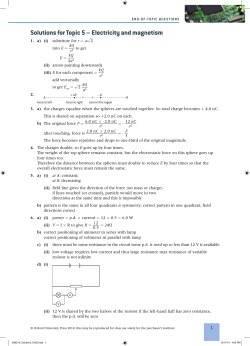


© Copyright 2026