
A medium-rise 1970s maternity hospital in the east of England
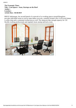
Loughborough University
Institutional Repository
A medium-rise 1970s
maternity hospital in the east
of England: resilience and
adaptation to climate change
This item was submitted to Loughborough University's Institutional Repository
by the/an author.
SHORT, C.A., GIRIDHARAN, R. and LOMAS, K.J., 2015. A
medium-rise 1970s maternity hospital in the east of England: resilience and
adaptation to climate change. Building Services Engineering Research and Technology, 36 (2), pp. 247 - 274.
Citation:
Additional Information:
• This article is distributed under the terms of the Creative Commons Attri-
bution 3.0 License (http://www.creativecommons.org/licenses/by/3.0/)
which permits any use, reproduction and distribution of the
work without further permission provided the original work is
attributed as specied on the SAGE and Open Access pages
(http://www.uk.sagepub.com/aboutus/openaccess.htm)
Metadata Record:
Version:
https://dspace.lboro.ac.uk/2134/17060
Published
Publisher: SAGE Publications Ltd.; The Chartered Institution of Building
Services Engineers
This work is made available according to the conditions of the Creative
Commons Attribution 3.0 Unported (CC BY 3.0) licence. Full details of this
licence are available at: http://creativecommons.org/licenses/by/3.0/
Rights:
Please cite the published version.
Article
A medium-rise 1970s maternity
hospital in the east of England:
Resilience and adaptation to
climate change
Building Serv. Eng. Res. Technol.
2015, Vol. 36(2) 247–274
! The Chartered Institution of Building
Services Engineers 2015
DOI: 10.1177/0143624414567544
bse.sagepub.com
C Alan Short1, Giridharan Renganathan2
and Kevin J Lomas3
Abstract
The late 1970s design for the Rosie Maternity Hospital on the Addenbrookes campus in Cambridge is a
recurring type across the UK National Health Service, a framed three-storey courtyard configuration in
brick masonry. It was selected as a case study project for the ‘Design and Delivery of Robust Hospitals in a
Changing Climate’ project, pursuing the methodology developed for that research. Temperature data
were collected in representative spaces within the hospital, over a two-year period. These revealed
overheating in mild conditions relative to an observed 24 C threshold for sleep but concealed within
the customary 28 C threshold marking the upper limit of acceptable conditions. The building was modelled using current climate data to predict 2010 conditions. The model was then calibrated against the
observed 2010 data and used to predict the likely internal temperatures in current and 2030s. The results
indicated an increase in peak temperatures. Four adaptive intervention schemes were subsequently
developed: an ‘enlightened’ industry standard ‘Passivhaus’-type option providing superinsulation, sealed
glazing and heat recovery; a lower technology-based scheme promoting natural cross-ventilation by
providing greater opening glazing area, opening up the plan, sunshading and additional insulation; an
enhanced natural ventilation scheme glazing over the courtyards to provide supply air winter gardens,
and an advanced natural ventilation option pursuing passive downdraught cooling. All four schemes were
modelled using the projected current and 2030s weather data and their performance was compared. The
schemes were fully costed to yield relative ‘value for money’ guidance to National Health Service Trusts.
Practical application: The Heat wave Plan for England 2014 warns National Health Service (NHS)
organisations of the risks to patients, particularly the very young, the elderly and the seriously ill, from
extreme summer heat events.1 The Chief Medical Officer in her introduction challenges each NHS locality
to plan well in advance of hot spells, as appropriate. This paper describes the likely extent of overheating
risk and a series of potential adaptation plans for a recurring NHS hospital building type. As a consequence, estates and facilities decision makers in NHS organisations and Public Health England officers
1
Department of Architecture, University of Cambridge,
Cambridge, UK
2
Kent School of Architecture, University of Kent, Canterbury,
UK
3
Civil and Building Engineering, University of Loughborough,
Loughborough, UK
Corresponding author:
C Alan Short, Department of Architecture, University of
Cambridge, 1-5 Scroope Terrace, Trumpington Street,
Cambridge CB2 1PX, UK.
Email: [email protected]
Creative Commons CC-BY: This article is distributed under the terms of the Creative Commons Attribution 3.0
License (http://www.creativecommons.org/licenses/by/3.0/) which permits any use, reproduction and distribution
Downloaded from bse.sagepub.com at Loughborough University on March 19, 2015
of the work without further permission provided the original work is attributed as specified on the SAGE and Open Access pages
(http://www.uk.sagepub.com/aboutus/openaccess.htm)
248
Journal of Building Services Engineering Research & Technology 36(2)
charged with the mitigation of risk resulting from overheating of wards and clinical spaces will benefit
directly in their necessary decision making from the findings. Policy makers in the Department of Health
and policy advisors in the NHS Sustainable Development Unit and the Climate Change Committee
Adaptation Sub-Committee will benefit from the evidence presented in advising the NHS and
Department of Health.
Keywords
Hospitals, resilience, adaptation, climate change, mixed mode
Introduction
From 2009 until 2013, the Design and Delivery
of Robust Hospital Environments in a Changing
Climate (DeDeRHECC) research project investigated the impact of summer overheating in the
built estates of four National Health Service
(NHS) Acute Trusts: Addenbrookes Hospital
within the Cambridge University Hospitals
NHS Foundation Trust; Bradford Royal
Infirmary within the Bradford Teaching
Hospitals NHS Foundation Trust; St. Albans
City Hospital within the West Hertfordshire
NHS Trust and Glenfield Hospital, a Nucleus
scheme within the University Hospitals of
Leicester NHS Trust. In each of these hospitals,
125 spaces within three to four wards in two or
more buildings were monitored from June 2010.
In Cambridge, the Addenbrookes Hospital ward
tower and the Rosie Maternity Hospital were
analysed. The performance of Addenbrookes
tower has been presented elsewhere.2 This
paper focuses on the Rosie Maternity Hospital,
representative of a recurrent 1970s NHS
hospital-type building.
The Rosie hospital accommodates the maternity and neonatal services offered by the
Cambridge
University
Hospitals
NHS
Foundation Trust in the East of England.3 It was
funded by a single private donation, designed by
the architects Yorke Rosenberg and Mardell
(YRM) in the late 1970s and opened in 1983. It
comprises a steel and concrete-framed, brickclad, three-storey, double-loaded corridor,
double courtyard building.4 Recently, as yet
unpublished research, at Cambridge University
for the Department of Health (DH) indicates the
retention of some 117 postwar, three-storey,
courtyard-type buildings across the NHS
England Acute Estate, approximately 3 million
m2 alone. YRM delivered the St. Thomas’s tower
in Central London and the John Radcliffe
Hospital in Oxford. The framed, repetitive bay,
glazed treatment is consistent. Writing particularly of F. R. S. Yorke, YRM’S founder and an
important publicist for modern architecture,
Worsley wrote, ‘it was the rise of the Welfare
State that made his firm’.5 The ‘Rosie’ is a recognizably YRM design in the rigorous expression of
its frame, ultimately a building system and aesthetic derived from Mies van der Rohe’s theoretical prewar schemes via Skidmore Owings and
Merrill’s extensive output in North America,
within which wide structural bays are entirely
filled with glazing to a rectilinear grid. YRM’s tendency to clad their frames with ceramic tiles, as at
St. Thomas’s in London, was overruled by the
donor who insisted on brick and possibly also on
the generous provision of opening glazing, which
was suppressed in the late 1990s when urgent reactive NHS guidance suggested window opening be
restrained to 100 mm.6
The building is oriented approximately east–
west so that the main entrance and many of the
multibed wards face south. Clinical services for
outpatients examination, imaging and consulting rooms, are located on the level 1 (ground
floor), whilst inpatient wards occupy second
and the third levels. Figures 1–3 show general
plan layouts with the location of data loggers
Downloaded from bse.sagepub.com at Loughborough University on March 19, 2015
Short et al.
249
installed by researchers. There are parallel academic and research functions, the Cambridge
University Departments of Gynaecology and
Obstetrics have accommodation in the northwest quadrant.
This paper investigates the performance of
Rosie Maternity Hospital during summer 2010,
and simulates the performance of adaptive interventions with a focus on summer time overheating. The study also costed all the schemes to yield
relative ‘value for money’ guidance to NHS
Trusts. The simulation weather files for the year
L og g e r
1
2
3
4
5
6
7
8
9
Space
Office
Examinatio n
Office
Examination (ultrasound)
Assessment (ultrasound)
Assessment (ultrasound)
M ai n R e c e p t i o n
Main Waiting Area
Main Waiting Area
2010 (Bedford), current and future were created
by the ‘Prometheus’ research team at Exeter
University. The Bedford weather file was selected
because the weather station at Cambridge does
not measure all the necessary parameters to generate simulation weather files, especially the
cloud cover and solar radiation intensity.
The current Test Reference Year (TRY) and
the Design Summer Year (DSY) were generated
to the standard Chartered Institution of Building
Services Engineers (CIBSE) methodology using
weather data from the Bedford meteorological
Logger reference
AR1-OF101
AR1 -EX104
AR1-OF102
AR1-EX105
AR1-EX101
AR1-EX102
AR1 -L B01
AR1-LB02
AR1-LB03
Figure 1. Monitored spaces and logger locations in Rosie level 1. AR1-EX was considered for predicted performance analysis (space with logger 5 and 6).
Downloaded from bse.sagepub.com at Loughborough University on March 19, 2015
250
Journal of Building Services Engineering Research & Technology 36(2)
L og g e r
1
2
3
4
5
6
7
8
9
10
11
12
13
14
15
16
Space
Office
Office
Office
Office
Single Bedroom
Single Bedroom
Meeti ng R oom
Meeti ng R oom
C o r r id or
Examination Roo m
Examination Roo m
Single Bedroom
Nurse Stati on
M u l t i B e d ro o m
Multi Bedroom
C or r i d o r
Logger reference
AR2-OF202
AR2-OF201
AR2-OF102
AR2-OF101
AR2-S3101
AR2-SB201
A R 2 - MR 1 01
A R 2 - MR 1 02
A R 2 -C D 0 3
AR2 -EX 101
A R2 -E X 1 02
AR2-S B101
AR2 -NS
A R2-M B 101
A R2-M B 102
A R 2- C D 0 2
Figure 2. Monitored spaces and logger locations in Rosie level 2. AR2-MB2 was considered for predicted performance analysis.
station. The TRY was created using 1980–2004
hourly weather data. The DSY was the year that
had the third hottest summer between 1980 and
2004. In this case, it was 1997. For the year 2010
as well as for the current TRY and DSY, the
diffused solar radiation, direct solar radiation
and global solar radiation were derived from
Bedford cloud cover as directed by CIBSE
TM48. The future probabilistic weather files
were derived using UKCP09 data for
Cambridge under the A1B emission scenario.7
The Prometheus team used a statistical technique
to derive a single TRY and DSY for the future
time slice. This work used 50 and 90 percentile
weather files to generate the TRY and DSY,
respectively. A detailed account of the weather
file generation and selection process has been presented elsewhere.8
Downloaded from bse.sagepub.com at Loughborough University on March 19, 2015
Short et al.
L og g e r
1
2
3
4
5
6
7
8
9
10
251
Space
Office
Examination
Nurse station
De li ve ry Ro om
Day Room
Office
C or ri d o r
Special Care Baby Unit
Special Care Baby Unit
Special Care Baby Unit
Logger reference
AR3-OF02
A R 3 -E X 01
AR3-NS
AR3 -DR0 1
AR3-DY01
AR3-OF01
A R 3- C D 0 1
AR3-SCBU101
AR3-SCBU102
AR3-SCBU103
Figure 3. Monitored spaces and logger locations in Rosie level 3. AR3-DR was considered for predicted performance analysis (space with logger 4).
Construction of the Rosie hospital
Figures 1–3 record the three floor plans of
the hospital, Figures 4 and 5 show the frame
structure. Table 1 summarises the use of
materials.
Floor and roof slabs are coffered ‘waffle’ type
reinforced concrete slabs of 150 mm continuous
slab depth with two way beams adding 300 mm
depth, 450 mm overall incorporating substantial
thermal mass, spanning across a steel frame.
Deep perimeter downstands to the floor and
roof slabs form lintols to the wide bays. The
roof buildup comprises screed to falls, asphalt,
50 mm ‘Roofmate’ extruded polystyrene slabs,
held below a 50 mm thick roof deck of prescreeded woodwool slabs with reinforced edges
and 50 mm thick layer of washed gravel
(20–50 mm diameter).
Suspended ceilings conceal all spanning concrete from the occupied spaces, suppressing radiant exchange with the occupants. The
conventional cavity external wall construction
comprises: 100 mm brick; 50 mm thick polystyrene partial cavity fill; the inner leaf either 140 mm
block
or
plaster
board
on
timber
(100 mm 100 mm) studwork; the floors
Downloaded from bse.sagepub.com at Loughborough University on March 19, 2015
252
Journal of Building Services Engineering Research & Technology 36(2)
Figure 4. The Rosie Maternity Hospital, Addenbrookes, Cambridge. Existing Building, Summer Condition.
1. Reinforced concrete frame: waffle slab 150 mm with 300 mm downstands, from inner leaf to external cavity wall
above glazing spanning full structural bay.
2. External leaf of 100 mm brick, 50 mm polyurethane insulation in cavity, inner leaf 140 mm concrete blockwork.
Occasionally steel stud and two layers plasterboard.
3. Nonstructural internal partitions vary: plasterboard on 100 mm softwood studwork or 140 mm concrete blockwork plastered both sides.
4. External windows double glazed in hardwood frames, mullions and transoms (75 100 mm), opening lights
restricted to 100 mm since late 1990s.
5. Roof: 150 mm RC slab, waffle 300 mm deep, 50 mm roof deck of prescreeded slabs with reinforced edges, asphalt,
50 mm extruded polystyrene ‘Roofmate’ held down by 50 mm of washed gravel.
6. Lightweight suspended gypsum ceiling tile grid.
7. Hot water (HW) pipes suspended within ceiling void, original insulation, some missing, water circulated at 55 or
60 C continuously to avoid bacterial growth.
8. Service riser to east and to west sides. Each connects to a plant room on ground floor (level 1) 3 AHU units in
east, fresh air supply drawn down riser ducts from roof level.
9. Supply air, 2 AHU’s heating, 1 AHU cooling per plant room. Unconditioned air supplied when external temperature below 22 C. Conditioned air delivered at 21 C through variable speed fan.
10. Exhaust air vented mechanically. No heat recovery.
11. Perimeter heating: thermostatic radiator valves recently installed (2011) supplied by HW at minimum 65 C.
Target temperatures 24–25 C in all rooms–wards.
12. Internal gains: TV 2.2 w/m2; bed lamp 2.8 w/m2; general ceiling mounted lighting 3.3 w/m2 as calculated for multibed ward.
screeded and finished with vinyl carpet. The rectilinear grid of windows in each structural bay is
double glazed in hardwood frames (approximately 75 mm 100 mm). Hot water and mains
steam pipelines are suspended below the floor
slabs retaining their original insulation at the
time of this study, some of which is missing. The
steam pipe, the main ring supplying the whole site,
Downloaded from bse.sagepub.com at Loughborough University on March 19, 2015
Short et al.
253
Figure 5. The Rosie Maternity Hospital, Addenbrookes, Cambridge Existing Building, Winter Condition.
1. Air leakage trough window frame.
2. Heat gains from uninsulated HW and particularly steam supply pipes.
3. Perimeter heating, HW supplied at 65 C.
4. Internal gains from lighting, bed lamp and TV.
5. Heat loss through poorly insulated fabric, essentially 50 mm polystyrene at wall and roof.
6. Warmed air exhausted at roof level.
7. Air supplied mechanically at 21 C+, mean target temperature 24–25 C.
Table 1. General construction information for the Rosie maternity ward complex.
Description Material
External
wall
Roof
Floor
Window
Thickness
(mm)
Brick/cavity/50 mm 400
insulation/plaster
board
RC frame
250
RC frame
Overall 450,
slab 150
Timber-framed
–
double glazing
Thermal
transmittance Opening
(Wm2 K1) size (mm)
0.4
–
0.5
0.15
–
–
1.9
675 1300
675 650
General information
The floor to floor and floor to
ceiling heights are 3.8 m and
2.5 m, respectively, in levels 1
and 2. In level 3, floor to floor
and floor to ceiling heights are
3.9 m and 2.4 m, respectively.
The window opening is
restricted to 100 mm for
patient safety
Note: RC, reinforced concrete.
Downloaded from bse.sagepub.com at Loughborough University on March 19, 2015
254
Journal of Building Services Engineering Research & Technology 36(2)
emitted heat continuously into the Level 2 ceiling
void on the north side of the building. Recently
the DH NHS Energy Efficiency Fund (EEF),
administered by the lead author, has funded its
reinsulation and the removal of asbestos lagging.9
Arrangement of existing services
All spaces have perimeter heating elements without local thermostatic control, set within each bay
below the extensive glazing, fed by supply and
return pipes rising through the floor slab below,
hot water reaching the perimeter radiators
intended to be not less than 65 C, to maintain
24–25 C in occupied rooms year round. The
building is currently operated at a set point temperature of 24.0 C. Mechanical ventilation heats
supply air at temperatures below 22 C all year
round. At the time of monitoring, there was no
zone control. However, the Trust’s Estate
Management was planning to introduce
Thermostatic Radiator Valve (TRVs). The
researchers’ expert panel observed that zone control employing wall-mounted thermostats would
be more productive and efficient.10 The Rosie hospital has its own plant room on level 1 of the west
wing with four noncondensing duel fuel boilers,
gas fired in normal mode. They supply hot water
to the main header maintained at 60 and 70 C,
respectively, in summer and winter temperature.
The boilers come to operation in sequence during
colder conditions to supplement heat provided by
central steam plant supplying the whole site. The
plant on site includes two shell–core heat exchangers to extract heat from the steam supplied from
the central plant. The original exchangers are
scheduled to be replaced by plate exchangers.
Pumps work on constant volume and variable
temperature.
The building has its own chiller providing
chilled water to an air-handling unit (AHU)
delivering comfort cooling to intensive care
units and the operating theatres. The chiller set
point temperature is 6 C. Standby mode set
point is 9–10 C. When the chiller is not supplying chilled water to the cooling circuit, the temperature is set at 12 C.
The building is mechanically ventilated
throughout the year. Figures 4 and 5 show the
supply and exhaust points, corridor pressurized
by supply, exhaust above patient beds. For ventilation, the building is zoned into east and west
wings with an AHU room located on each side.
Each plant room contains three AHU units and
in each room only one unit has the provision to
cool the air (the other two are only for heating).
Fresh air to these AHUs is drawn from above
roof level through ducts. Generally, when the
outside air temperature is 22 C or above the
fresh air is not conditioned (no heating) and it
is directly supplied, but cooling is produced for
special rooms such as the Special Care Baby
Unit. The AHUs release the conditioned air at
21 C through variable speed fans. Fresh air is
heated to 18 C and supplied to each zone via corridor ceiling supply grilles located. Anticipated
maximum supplied air temperature is around
26 C in summer. In the winter, it could fall as
low as 18 C. At night, level 1 has reduced air
supply due to low occupancy.
Extracts are located in service spaces, WCs,
bathrooms and dirty utility rooms and in wards
above beds. The centrally collected return air is
released directly to the atmosphere above roof
level with no heat recovery.
Performance of monitored spaces
Twenty-six spaces on three levels were
monitored at hourly intervals with Hobo U2
temperature loggers.11 The larger spaces
receive more than one logger (Figures 1–3).
The logger positions were constrained as
NHS infection control protocols resist foreign
objects appearing in clinical spaces. Specific ventilation rates were recorded using a Balometer
on a typical working weekday during January
2012.
The second level emerges as the hottest floor
and AR2-SB2 (logger AR2-SB201) records the
hottest space (Figure 6).12
Basic construction information and the
mechanical servicing strategy are presented in
Table 2.
Downloaded from bse.sagepub.com at Loughborough University on March 19, 2015
35
2400
30
2000
25
1600
20
1200
15
800
10
400
5
0
1st July 2010
Cambridge EXT
AR2-SB101
AR2-OF102
30th September 2010
to
AR2-CD01
AR2-SB201
AR2-OF201
AR2-EX01
AR2-MR101
AR2-OF202
AR2-MB101
AR2-CD02
Running mean
Solar radiation intensity (SRI) W/m2
255
Dry bulb temperature °C
Short et al.
0
AR2-MB102
AR2-OF101
Bedford SRI
Figure 6. Recorded Rosie level 2 internal and ambient dry-bulb temperature and solar radiation intensity.
Table 2. Multizone base model characteristics: selected spaces.
Description
AR1-EX
2
External wall area (m )
Floor area (m2)
Volume (m3)
Window area (m2)
Internal heat gain (W/m2)
Perimeter heating
Mechanical ventilation rate
Window-opening strategy
Perimeter heating regime
Ventilation heating regime
Extract regime
Occupancy
AR2-MB2
AR3-DR
40.3
17.3
8.5
96.1
50
16.3
231
120
39
23.4 glazed and 6.6 opaque
10.1 glazed and 2.5 opaque
NA
0–14.6
10.8–22
0.8–2.0
Yes
Yes
Yes
32 l/s (0.5 ach)
40 l/s (1.2 ach)
6 l/s (0.5 ach)
The occupants were assumed to open the windows. The maximum opening is
100 mm. The opening area assumed to be 0% if the Tout 10 C, and 50% if
Tout > 10 C and Tin 24.5 C, then ramps up to 100% at Tin 25.5 C
Set point temperature is 24.5 C. Set point is 100% at Tout 3 C and it
ramps down to 75% at Tout ¼ 15 C. It is off at Tout ¼ 18 C
Supply air is heated to 18 C. Set point ramped down from 100% at
Tout 16 C to zero at Tout 18 C
40–50% of the stale air is extracted through service areas and the balance
escapes through window openings
The occupancy levels in AR1-EX, AR2-MB, AR3-DR were 17 (5 staff, 6 patients
and 6 visitors), 13 (3 staff, 6 patients and 4 visitors) and 4 (2 staff, 1 patient and
1 visitor), respectively. Between 7:00 and 9:00, and 18:00 and 20:00 at every
hour there were two staff members at the multi bedroom for 5 min. The rest
of the time at every hour, there was one staff member at the multi-bedrooms
Note: AR2-MB2 was not monitored. However, it was selected in order to assess the performance of south facing multi-bedroom.
Downloaded from bse.sagepub.com at Loughborough University on March 19, 2015
256
Journal of Building Services Engineering Research & Technology 36(2)
Discussion will be limited to the main lobby
area (AR1-LB), the examination–consulting–
meeting room (AR1-EX), the multi-bedroom
ward (AR2-MB1), a single bedroom (AR2SB2), a delivery room (AR3-DR) and a nurse
station (AR3-NS), all as described in Tables 3
and 4. The spaces were selected to present a representative overview of all the critical types of
space found in the Rosie hospital.
The spaces were monitored from July 2010 to
October 2011. The focus of the DeDeRHECC
research project is on resilience to summer overheating and so results for the consecutive
summer periods 1st July to 30th September
2010 and 1st May to 30th September 2011 are
presented (Tables 3 and 4). Analysis will focus
on 2010 results insofar as calibration of the
dynamic thermal model, the predictions it generated and the subsequent energy calculations
are based on the 2010 Bedford weather file as
described later in the paper.
To evaluate the monitored performance, the
study used the ambient temperature from
Cambridge University and solar radiation intensity from the Bedford meteorological station.
The maximum ambient temperature during the
summers of 2010 and 2011 were 29.6 C and
31.2 C respectively, 2010 was a relatively cool
year, while the minimum temperatures for
summer 2010 and 2011 were 5.2 C and 3.5 C,
respectively. The peak solar radiation intensity
for 2010 and 2011 was of the order of 750 W/m2
and 950 W/m2, respectively, for the monitored
periods.
During the period 1st July to 30th September
2010, the maximum temperature recorded in the
building was 30.7 C observed in the single
patient bedroom (AR2-SB2). This trend was
also observed during summer 2011. During the
2010 monitored period, a minimum temperature
of 20.3 C was found in the Lobby area and this
trend repeated in 2011. For the 2010 monitored
period, the mean daytime temperature varied
between 23.9 C and 26.7 C, while mean nighttime temperatures varied between 23.4 C and
26.1 C. The single bedroom (AR-SB2)
experienced the maximum temperature conditions recorded. The lowest diurnal temperature
range, 2.8 K, was recorded in the nurse station
(AR3-NS) and the highest, 6.6 K, in the delivery
room AR3-DR.
Thermal comfort was determined by comparing the measured temperatures with the criteria adopted in previous papers by the
authors.13 These included both the simple
static guidelines and criteria described by the
CIBSE and the adaptive thermal comfort
thresholds described in BSEN15251. The
appropriateness of these approaches and their
relative credibility are discussed by Lomas and
Giridharan.14 The static criteria suggest that
thermal discomfort will arise if there are
more than 5% of the annual occupied hours
over 25 C or more than 1% of annual occupied hours over 28 C in occupied spaces. The
research team assumed throughout the
DeDeRHECC project that hospital wards are
occupied for 24 h a day every day of the year,
with the exception of the lobby, consulting
and examination rooms.
The latter criterion is given in Healthcare
Technical Memorandum HTM03.15 The
CIBSE Guide also indicates that sleep will be
impaired if temperatures exceed 24 C and that
they should not exceed 26 C. However, the
nighttime overheating risk criterion indicates
that temperatures should not exceed 26 C for
1% of the occupied hours. Nighttime was
taken as 21:00 to 06:00 throughout the
DeDeRHECC project. The BSEN15251 thresholds increase as the ambient air temperature
increases; a narrow band of acceptability,
Category one (Cat.I) which is 5 K wide, and a
wider band, Cat.II of 7 K, are of interest here.
In 2010, the single bedroom (AR2-SB2) and
examination room (AR1-EX1) exceeded both
BSEN15251 and HTM03 thresholds.16
The multi-bedroom ward and delivery room
exceeded only the CIBSE criterion. None of the
spaces met the adaptive comfort standard
Cat.I.17 However, the examination room
(taking the average value of two loggers) and
Downloaded from bse.sagepub.com at Loughborough University on March 19, 2015
AR3-NS
AR3-DR01
AR2-SB201
AR2-MB101
AR2-MB102
28.3
29.9
30.7
29.4
29.4
29.3
AR1-EX102
26.5
29.6
AR1-EX101
AR1-LB03
28.8
29.0
AR1-LB01
AR1-LB02
Logger
reference
22.2
18.2
22.3
20.0
18.1
20.0
21.4
20.5
20.8
20.3
Minimum
temp C
(24 h)
25.0
24.8
26.7
24.5
24.1
24.6
25.8
23.9
24.4
24.5
Mean daytime
temp C
(7:00 to 20:00)
24.4
24.7
26.1
24.1
23.5
24.0
24.6
23.4
23.6
24.0
Mean night
time temp C
(21:00 to 6:00)
2.8
6.6
4.9
5.6
6.5
6.2
5.4
4.3
4.5
4.8
Maximum
diurnal
range (K)
525
610
661
1992
595
466
734
1174
63
485
4
3
236
19
23
51
94
0
6
9
HTM03:
Hours
over
28 C
(24 h)
NA
512
888
488
302
NA
NA
NA
NA
NA
Hours
over
24 C
(21:00 to
6:00)
NA
81
494
55
46
NA
NA
NA
NA
NA
CIBSE: Hours
over 26 C
(21:00 to 6:00)
NA
598/114
1972/1168
376/90
293/74
514/188
977/454
65/2
245/40
255/53
BSEN15251:
Hours
over Cat I/
Cat II upper
Note: Total number of hours: 2208. Total number of night time (21:00 to 6:00) hours: 920. The loggers AR1-LB03, AR3-DR01 and AR3-NS were in operation between 27st July
and 30th September. There were 1571 h. Nighttime hours: 653. The limiting overheating values for the monitored period are: HTM03, 30 h over 28 C; BSEN15251, 110 h
above category upper threshold and CIBSE, 9 nighttime hours over 26 C. For the loggers AR1-LB03, AR3-DR01 and AR3-NS, the limiting overheating values are: HTM03, 21 h
over 28 C; BSEN15251, 79 h above category upper threshold and CIBSE, 7 nighttime hours over 26 C. Nighttime sleeping criteria are not applicable to lobbies, examination
rooms and nurse stations. Boldface and italic values with grey shade: criterion limit exceeded. AR2-MB2 was not monitored. However, it was selected in order to assess the
performance of south facing multi-bedroom.
Nurse station
(AR3-NS)
Level-3
Delivery room
(AR3-DR)
Single bedroom
(AR2-SB2)
Level-2
Multi bedroom
(AR2-MB1
Examination–
meeting cum
consultation
(AR1-EX)
Level-1
Main lobby
(AR1-LB)
Space
Maximum
temp
C (24 h)
Hours
over
25 C
(24 h)
Table 3. Comparison of internal temperatures measured between 1st July and 30th September, 2010, with BSEN15251, CIBSE and HTM03 overheating
criteria: Representative spaces in Rosie maternity ward.
Short et al.
257
Downloaded from bse.sagepub.com at Loughborough University on March 19, 2015
AR3-NS
AR3-DR01
AR2-SB201
30.0
29.2
30.4
29.7
29.9
30.1
AR1-EX102
AR2-MB101
AR2-MB102
30.1
28.2
AR1-LB03
AR1-EX101
28.1
28.9
AR1-LB02
AR1-LB01
Logger
reference
21.5
19.7
22.7
20.2
18.5
19.7
20.6
18.8
18.7
19.9
Minimum
temp C
(24 h)
25.3
24.7
25.8
24.5
24.2
23.6
24.7
23.7
23.8
23.7
Mean daytime
temp C
(7:00 to 20:00)
24.8
24.4
25.6
24.0
23.5
22.8
23.6
23.0
23.1
22.7
Mean night
time temp C
(21:00 to 6:00)
4.5
5.1
4.5
6.0
6.6
6.9
7.3
4.7
5.0
5.0
Maximum
diurnal
range (K)
1778
1169
2703
966
769
294
908
177
201
223
33
26
115
21
26
12
17
2
1
6
1256
1028
1486
762
504
NA
NA
NA
NA
NA
Hours
over
24 C
(21:00
to 6:00)
NA
81
491
65
47
NA
NA
NA
NA
NA
CIBSE: hours
over 26 C
(21:00 to 6:00)
489/59
205/33
1292/347
239/55
210/67
39/10
214/32
31/6
39/4
42/6
BSEN15251:
hours
over Cat I/
Cat II upper
Note: Total number of hours: 3672. Total number of night time (21:00 to 6:00) hours: 1530. The limiting overheating values for the monitored period are: HTM03, 50 h over
28 C; BSEN15251, 184 h above category upper threshold and CIBSE, 15 nighttime hours over 26 C. Nighttime sleeping criteria are not applicable to lobbies, examination
rooms and nurse stations. Boldface and italic values with grey shade: criterion limit exceeded.
Nurse station
(AR3-NS
Level-3
Delivery room
(AR3-DR)
Single bedroom
(AR2-SB2)
Level-2
Multi bedroom
(AR2-MB
ExaminationMeeting cum
consultation
(AR1-EX)
Level-1
Main lobby
(AR1-LB)
Space
Maximum
temp C
(24 h)
HTM03:
Hours
over 28 C
(24 hours)
Table 4. Comparison of internal temperatures measured between 1st May and 30th September, 2011, with BSEN15251, CIBSE and HTM03 overheating
criteria: Representative spaces in Rosie maternity ward.
258
Journal of Building Services Engineering Research & Technology 36(2)
Downloaded from bse.sagepub.com at Loughborough University on March 19, 2015
Short et al.
259
the lobby met the Cat.I threshold during 2011.
On the other hand, during 2011, only the single
bedroom (AR2-SB2) exceeded the HTM03
threshold. In 2010, most of the spaces were
monitored for 2208 h, however the number of
hours crossing the threshold is close to, or
higher than 2011 values, especially in terms of
the BSEN15251 thresholds. On the other hand,
the number of hours of ambient temperature
over 24 C during 2010 (2028 h) and 2011
(3672 h) was 82 and 96, respectively. Therefore,
better performance in 2011 can be attributed to
milder summer conditions. However, in general,
the 2010 summer has been considered as mild
summer, not taxing conditions.18 Therefore,
these results indicate that summer overheating
even in mild ‘normal’ conditions in the Rosie
hospital is a major concern.
Overheating has been highlighted by hospital
staff on many occasions during the researchers’
visits to Rosie Maternity Hospital. Excessive
temperatures have been recorded by the
DeDeRHECC team in the Bradford Royal
Infirmary and the Edinburgh Evening News
reported ‘Soaring heat at maternity ward
‘‘intolerable’’’ in its 24th July 2014 issue.
Figure 4 depicts the winter mode in which
unintended air infiltration through the envelope
and fabric heat losses do not appear to dispel the
significant internal heat gains. Mechanical ventilation delivers warmed air to achieve the set
point temperature and perimeter skirting heating attempts to counter the prodigious cold
down-draughting off the glazing.
The fundamental factors contributing to the
poor summer time resilience are indicated in
Figure 5. Hot water and steam pipes with intermittent insulation contribute to significant internal heat gains from lighting and equipment.
The diagram reveals the extent of the exposure
of direct solar gains through the liberal glazing
area, which is largely fixed but with an intermediate band of lights opening to only
100 mm. This explains the marginal thermal
comfort generated on even mild days in south
and south westerly facing wards as shown in
Figure 5.
Predicted performance of the existing building: Modelling and
calibration
To predict the annual frequency of overheating
of the wards and the energy demands and CO2
emissions in the current climate, the dynamic
thermal model Integrated Environmental
Solutions (IES) was used.19 This software was
chosen because it is widely used by UK building
engineering consultancy firms including partners
in the ‘DeDeRHECC’ project. Its application to
the refurbishment of hospitals would thus meet
with general understanding and interest in the
industry. Since measured temperatures were
available, it was possible to calibrate the IES
model prior to embarking on the assessment of
the proposed refurbishment options.
A multizone thermal dynamic model of the
Western wing of the Rosie hospital was constructed to predict current and future performance. The measured hours over 28 C was taken
as the primary criterion to be matched by the
predictions. Table 2 records the construction
information on which the model was run. The
calibration was carried out by focusing on two
spaces; AR1-EX and AR3-DR (Figures 7–9).
The weather file for Bedford in 2010 was used
for the calibration, as described elsewhere.20
Sensitivity analysis was carried out to identify
the critical variables necessary to tune the
model. The model is sensitive to internal gains,
especially heat gains from the equipment, the
degree and duration of both window and door
opening in all the rooms.
At night, the model assumes that in any 1 h,
50% of the doors were opened for 5 min in discussion with nursing staff. The window-opening
regime (see Table 2) is one of the most uncertain
assumptions but is very critical, especially in
making nighttime predictions.
Entry onto wards for researchers was limited
to brief forays to install or collect data loggers
and on some days forbidden outright. The
model cannot accurately reflect an individual’s
preferences, i.e. the window-opening regime will
not change in line with each and every occupant
Downloaded from bse.sagepub.com at Loughborough University on March 19, 2015
260
Journal of Building Services Engineering Research & Technology 36(2)
35
Dry bulb temperature °C
30
25
20
15
10
5
0
1st July 2010
Cambridge EXT
to
30th September 2010
Measured
Bedford EXT
Predicted
Figure 7. Comparison of predicted and measured temperatures for AR1-EX, and ambient temperature, during the
monitored period.
35
Dry bulb temperature °C
30
25
20
15
10
5
0
27th July 2010
Cambridge EXT
to
Measured
30th September 2010
Predicted
Bedford
Figure 8. Comparison of predicted and measured temperatures for AR3-DR, and ambient temperature, during the
monitored period.
Downloaded from bse.sagepub.com at Loughborough University on March 19, 2015
Short et al.
261
General extract
Dirty extract
Supply
R2 - 0F102
R2 - 0F202
R2 - 0F201
R2 - 0F101
R2 - SB301 R2 - SB201
R2 - CD02
R2 - CD01 R2 - SB101
R2 - MR01
R2 - MB102
R2 - MB101
R2 - EX01
R2 - NS
Figure 9. Option 1 SMVHC.
1. Ventilation system delivers 6 ach1 as required by HM 03-01.
2. Return air ducts in corridors and wc/bathrooms.
3. Windows are sealed shut.
4. South and west facing glazing shielded by interstitial blinds. Airtightness improved by continuous mastic seal.
5. Perimeter heating not utilised in this option.
6. Existing HW and steam supply pipes insulated to high standard.
7. Additional 100 mm insulation added to 50 m Roofmate extruded polystyrene slabs.
8. Walls receive 100 mm mineral fibre insulation and proprietary render treatment. Lower opaque-glazed panels to
window frames receive additional 100 mm insulation.
decision, but it is not clear how autonomous
inpatients and their visitors may be in practice.
Therefore, the model used a generalised windowopening profile that researchers believe to reasonably reflect the overall trend in the ward
from limited accounts by nurses and spot observations of the exterior elevations (see Table 2).
Experiments have shown that the largest difference between measured data and predictions
occur during periods of high solar radiation
intensity (solar gain) and high airflow rate. The
deviations during high solar radiation intensity
could be attributed to the weather file used for
the simulation i.e. in real situation; solar radiation intensity could have been less than that in
the constructed Bedford simulation weather file.
The model takes into account shading by the
building to the west but not winter morning
Downloaded from bse.sagepub.com at Loughborough University on March 19, 2015
262
Journal of Building Services Engineering Research & Technology 36(2)
Table 5. Comparison of measured and predicted results of three monitored spaces for the calibration period.
Space reference
AR1-EX
AR3-DR
Measured
Predicted
Measured
Predicted
Max.
temp
( C)
Min.
temp
( C)
Mean
night time
temp
( C)
29.3
29.4
29.9
28.2
20.8
20.7
18.2
22.2
24.3
24.5
24.7
24.5
HTM03:
total
hours
over
28 C
CIBSE:
Nightt ime
hours over
26 C
BSEN15251:
total hours
above Cat I
upper limit
BSEN15251:
total hours
above Cat II
upper limit
60
25
3
4
NA
NA
81
0
745
535
598
443
321
165
114
111
Note: Calibration period for AR1-EX and AR2-MB is 1st July to 30th September 2010. Calibration period for AR3-DR is 27th July to
30th September 2010. On most occasions predicted nighttime value for AR3-DR is marginally below 26 C.
shading from the east. Overall, the deviations of
the predicted temperatures during high solar
radiation intensity are not significant. The
model-predicted temperatures were not very sensitive to the prevailing mechanical ventilation
rate, but were sensitive to high natural ventilation rates via windows.
The predicted maximum temperatures of all
the spaces were in reasonable agreement with
the measured values (Table 5). In overheating
studies, the reliable prediction of peak temperatures is important and any deviation should not
exceed 2 C. In this context, the model could be
considered reliable.21
The mean nighttime temperature shows a
good agreement with the measured values for
both the spaces (Table 5). The deviation in
HTM03 value is slightly high in AR1-EX. This
is largely due to limitations in the schedules.
The NHS annual Heatwave Plan, released
when DH determines external temperatures
have reached a predetermined limit. The criterion for implementation varies across the country, being higher in the southeast to
acknowledge adaptation to the prevailing heat
island. The effectiveness of what are emergency
short-term measures has been found to be
affected by behaviours and understanding.22
The building clearly requires longer term intervention to deliver greater resilience to current
and future summertime overheating.
Four adaptation refurbishment
options
Schemes to deliver greater resilience to hot summers were devised, commencing with what
appears to have become the ‘enlightened’ industry standard ‘Passivhaus’ model adapted to the
scale of the nondomestic building, a superinsulated envelope coupled with a rigorously controlled mechanical ventilation regime with
efficient heat recovery, through lower technology, perhaps more conventional, cross-ventilated schemes to atrium-type solutions
providing an air supply winter garden and in
the final option, a relatively very low energy
form of gravity-driven cooling.
Option 1, SMVHC: sealed mechanical ventilation heating and cooling (see Figures 9 and
10), proposes all glazing is sealed, airtightness
improved as far as practicable, 100 mm insulation added to the roof and, through an overcladding insulation and render system, to the
external walls. Mechanical ventilation is operated to achieve the unqualified DH recommendation of 6 ach with 60% heat recovery.
Figure 10 shows the basic duct layout.
Air cannot be recirculated within UK hospital
wards.
Option 2, NCVPH: natural cross-ventilation
retaining perimeter heating (Figures 11 and 12),
reintroduces natural ventilation as the primary
Downloaded from bse.sagepub.com at Loughborough University on March 19, 2015
Short et al.
263
7
1
2
7
8
4
3
3
4
6
5
Option 1
Figure 10. Option 1 basic mechanical ventilation arrangement.
ventilation strategy. This follows DH best practice guidance:
HTM 09-02 para 10.15 ‘Natural ventilation of
rooms should be employed wherever possible
and appropriate. Design should incorporate
measures for minimizing solar heat gains,
which, if controlled, will avoid the need for
mechanical ventilation. Measures to minimize
the need for cooling should include locating
temperature-sensitive accommodation away
from south-facing fascias, shading windows,
and using reflecting glass where appropriate
and cost-effective’.23 Para 10.16 suggests, tentatively, the potential benefit of passive nighttime
cooling.
This option proposes that the roof is insulated
further,
all
glazing
to
South,
Southwesterly and Southeasterly elevations
are shaded externally to eliminate direct
summer solar gains to reduce the scale of the
cooling problem, but preserving bedhead level
views out from the wards, all glazed panels to
open to 45 with the addition of panels below
existing cill lines, all applying to glazing to the
courtyard elevations within. Again this is in
line with current DH guidance. HTM 07-02
para 4.61 (p. 46) promotes ‘passive solar
design’, to ‘use the available daylight to its
full extent’ with provisos to avoid overheating
and glare.24 It cautions that in the modern
hospital setting, internal heat gains from activity and ever-increasing medical equipment may
preclude passive solar design.
Spaces adjacent to the courtyards are opened
out by the removal of cellular offices to become
patient day-spaces and encourage distributed
cross-ventilation (Figure 12). Suspended ceilings
are removed in these areas to reveal concrete
soffits to capture ‘coolth’ from cross-ventilation
from the shaded courtyards, transfer grilles and
ducts, as judged by cross-infection risk, connect
these inboard spaces to the perimeter.
Option 3, ANCSVPH: Advanced Natural
Cooling Summer Ventilation (see Figure 13)
through glazed atria and retaining perimeter
heating pursues a natural ventilation strategy
and proposes the enclosure of both courtyards
with glazed roofs. These become unheated atria
with liberal opening areas above to dissipate
summer solar gains and below slab air supply
via concrete ducts offering a measure of
ground cooling. All glazing to the atria becomes
operable to 45 . In winter mode, air is admitted
through damper-controlled perimeter heating
units. Transfer ducts exhaust air from zones
adjacent to the atria and again hung ceilings
are cut back to expose thermal mass. External
window guards deliver DH safety policy and all
vulnerable glazing is shielded from direct
summer solar gains. The option is capable of
further refinement by incorporating winter heat
recovery at the atrium head.
Downloaded from bse.sagepub.com at Loughborough University on March 19, 2015
264
Journal of Building Services Engineering Research & Technology 36(2)
11
8
3
5
11
4
8
3
1
4
9
2
9
10
10
6
6
10
10
6
6
10
10
6
6
9
9
3
2
9
3
9
3
3
N
3
S
Option 2
Figure 11. Natural cross-ventilation perimeter heating option 2 NCVH.
1. External sunshading applied to south, southeast, southwest elevations. Wing geometry of shade designed to
maximise view to upper sky, in translucent coloured material.
2. Existing timber window units, currently four upper panels open, restricted to 100 mm. All eight glazed panels
made openable to 45 with window guards to fulfill NHS safety regulations. Lower opaque elements to open to
admit air across perimeter heating units.
3. Perimeter heating below glazing.
4. Courtyard glazing units: all glazed panels opening to 45 protected by window guards.
5. Sunshading as (1) applied to southwest and southeast elevations.
6. Cellular rooms to centre of each elevation to courtyards removed to open circulation areas directly to courtyard
fresh air supply, become patient day areas.
7. Service risers maintained.
8. Suspended lightweight ceiling removed to expose concrete waffle slab.
9. Transfer grilles enable fresh air from courtyards to cross-sections.
10. Transfer ducts within suspended ceiling exhaust opened courtyard patient areas.
11. Additional 100 mm extruded polystyrene added to roof.
Option 4, NVPDCPH: natural ventilation
incorporating passive downdraught cooling
and perimeter heating (PDC) (see Figure 14)
also proposes the enclosure of the courtyards
but in a more active way, developing the lowenergy cooling strategy of the UCL School of
Slavonic and East European Studies SSEES
building in Central London.25 Cooled water
batteries at high-level openings induce a downward flow of precooled air which is contained
by a lightweight, acoustically absorbent, fabric
shroud. The cooled air is then drawn across
surrounding occupied spaces. The diagram
suggests ground-sourced cooling supplements
the action of the PDC by utilising thermal
storage, shown as readily available water
Downloaded from bse.sagepub.com at Loughborough University on March 19, 2015
Short et al.
265
Figure 12. Opening up of plan areas adjacent to courtyards to enhance cross-ventilation.
tanks, crossing the seasons so that heat gained
from summer hot spells is dissipated in winter
and winter coolth utilised in summer. Banks of
passive solar water heaters on the roof of each
PDC rooflight supplement warming of winter
supply tanks. Recovered heat from all sources
is gathered in winter to supplement the supply
to the perimeter heating system. Air is permitted to circulate within the twin summer
and winter storage chambers to a predetermined regime.
Predictions: Performance, energy
consumptions and CO2 emissions
Predictions focus on AR1-EX, AR2-SB2 and
AR3-DR for the building in its existing condition and the four adaptation scenarios. As per
2010 summer predictions, only AR3-DR
exceeded the HTM03 1%/28 C threshold substantially,
while
all
three
spaces
exceeded BSEN15251 CAT 1 significantly
(Table 6).
However, on most occasions AR3-DR only
marginally crossed the 28 C threshold. During
nighttime, both AR2-SB2 and AR3-DR
exceeded the CIBSE criterion. Table 7, in summary, reveals that in typical years, both current
and future TRYs, Option 1 generates the
lowest ‘overheating’ performance in all three
spaces, it incorporates mechanical cooling,
while the existing building exhibited the worst
performance.
In general, all three spaces under all four
options met the HTM03 threshold for current
as well as for future years except for AR3-DR
under option-2. However, the deviation is only
marginal. Further, three of the four spaces
met BSEN15251 Cat I and II under all
four options. Similarly, AR2-MB2 and
AR3-DR met the CIBSE nighttime criterion
as well.
Downloaded from bse.sagepub.com at Loughborough University on March 19, 2015
266
Journal of Building Services Engineering Research & Technology 36(2)
12
10
3
7
11
8
5
5
4
4
2
9
8
3
1
6
6
6
6
6
6
9
9
2
13
N
3
8
3
3
8
3
S
Option 3
Figure 13. Option 3.
1. External sunshading applied to south, southeast, southwest elevations. Geometry of shade designed to maximise
view to upper sky, in translucent coloured material.
2. Existing window units, currently four upper panels open, restricted to 100 mm. All eight glazed panels made
openable to 45 with window guards to fulfill NHS safety regulations. Lower opaque elements to open to admit
air across perimeter heating units.
3. Perimeter heating below glazing.
4. Courtyard glazing units: all glazed panels opening to 45 protected by window guards.
5. Additional 100 mm extruded polystyrene insulation added to roof.
6. Cellular rooms to centre of each elevation to courtyards removed to open circulation areas directly to courtyard
fresh air supply, become patient day areas.
7. Transfer ducts exhaust inboard spaces (6) to exterior.
8. Suspended lightweight ceiling removed to expose concrete waffle slab.
9. Transfer grills admit supply air from enclosed courtyard to wards.
10. Lightweight steel framed double glazed roof across internal courtyards with actuated fabric awnings to exclude
direct sunlight in overheating season.
11. Low-level actuated vents cross vent ‘atrium’, perform as smoke vents.
12. High-level lantern vents summer heat gains from upper part of atrium.
13. Low-level supply to atrium formed in spun concrete pipework.
During extreme years, DSY’s Option 1 projected the best performance in all three spaces,
while the existing building exhibits the worst
performance (Table 7). For the current DSY
extreme conditions, all four options broadly
met the HTM03 1%/28 C while for the 2030’s
Options 2–4 exceeded the HTM03 criterion.
Further, during the nighttime options 2–4
room, AR2-MB2 only marginally exceeded the
CIBSE criterion.
However,
improved
performance
is
achieved at a cost. Although the existing
Downloaded from bse.sagepub.com at Loughborough University on March 19, 2015
Short et al.
267
2
1
3
3
4
5
15
14
5
13
6
11
12
12
12
11
12
11
11
7 10
11
12
12
11
9
8
N
S
Option 4
Figure 14. Option 4 passive downdraught cooling PDC.
1. Solar water heating panels supply ‘winter’ tanks below courtyard.
2. Wind-catchers flush thermal storage chambers as required.
3. Opening glazed vents to exterior supply cooling batteries (5).
4. Internal opening glazed vents allow recirculation.
5. PDC cooling batteries.
6. Cone of acoustic absorbent material on light frame to direct PDC air flow.
7. Vent connects cooled water tanks chamber to external environment as required.
8. Cooled and warmed water tank enclosures formed below courtyard.
9. Flow and return to geothermal array via horizontal pipe to field or borehole.
10. Air admitted through opening vents in each bay of elevation.
11. Transfer ducts through outer corridor partitions.
12. Exhaust ducts connect courtyard-facing spaces to outer envelope.
13. Lightweight insulation on roof.
14. High-level vents to flush upper part of courtyard when PDC not engaged.
15. Glazed roof with retractable shading.
building, unaltered, has the worst thermal performance, it has the lowest energy consumption,
see Figure 15, and the lowest CO2 emissions, see
Figure 16.
The highest energy consumption and CO2
emissions are found in options 1 and 4,
respectively. Options 1–3 were within the
NHS refurbishment energy bench mark, while
Downloaded from bse.sagepub.com at Loughborough University on March 19, 2015
268
Journal of Building Services Engineering Research & Technology 36(2)
Table 6. Summary of predicted performance during the summer of 2010: Three selected spaces.
Space
reference
Max.
temp
( C)
Min.
temp
( C)
Mean
night time
temp ( C)
HTM03:
total
hours over
28 C
CIBSE:
nighttime
hours
over 26 C
BSEN15251:
Total hours
above Cat I
upper limit
BSEN15251:
Total hours above
Cat II upper limit
AR1-EX
AR2-MB2
AR3-DR
29.6
28.9
31.6
21.5
23.2
22.4
24.3
24.8
24.7
39
48
174
NA
81
52
980
1324
1159
342
548
541
Note: The HTM03 threshold is based on dry bulb temperature and rest are based on dry resultant temperature. CIBSE nighttime
condition is not applicable to nurse station and corridors since there is no provision for sleeping. BSEN15251 conditions are
applicable only to spaces with operable windows. It is assumed that during the period of October to April the spaces will not
overheat due to elevated ambient temperature and solar gains. Therefore, the limiting overheating values are: HTM03, 50 h over
28 C; BSEN15251, 438 h above category upper threshold and CIBSE, 37 nighttime hours over 26 C.
option 4 marginally exceeded. However, all
four options were within the CIBSE threshold
of 28 C.
Costs of implementing the four
options
Davis Langdon AECOM (‘AECOM’ is the
registered company name of this international
multi-disciplinary practice) undertook detailed
elemental costings from drawings and specifications produced by Short and Associates Ltd.
Architects. Table 8 shows that Options 1 and 2
do not add floor area to the existing building,
but Options 3 and 4 do by enclosing the courtyards, albeit as unheated spaces. Option 2,
embodying established sustainable refurbishment practice, is marginally more costly than
the first sealed building/heat recovery option
but value engineering may align these options
more closely to approximate £1000/m2, at the
lower end of current NHS refurbishment cost
as experienced by DeDeRHECC researchers
and the extensive Davis Langdon database. In
fact options 3 and 4, although of an order of
magnitude greater initial capital cost, at
£1500–1800/m2 are also within the realm of current investment.
Table 9 explores particular elemental costs
and assumptions by the cost consultant.
Design risk and fee elements affect the end cost
significantly. Design fees and design risk, a
contingency against late resolution of detail,
for the as yet uncharted PDC option are
double those for the familiar sealed building/
heat recovery option. Demolition costs incurred
in opening out the plan around the courtyards to
promote through ventilation also slew the figures. Transfer ducts and grilles would be a considerably cheaper option. Ceiling costs also
reflect the relative scale of internal rearrangement. Space heating and air treatment capital
costs are judged to be broadly similar for
options 1–3 and of an order of magnitude
greater for the PDC scheme. However, running
costs to deliver acceptable conditions will be
very different as Figure 15 suggests, considerably higher than current cost for all four
options, option 2 NCVPH being relatively the
lowest at some twice the energy demand of the
building as it exists.
Discussion and conclusions
The existing building enjoys a relatively low
energy and low carbon performance against the
DH guidance benchmarks but at the cost of comfort, it is unable to shed heat so that internal temperatures reach 28 C in relatively mild external
conditions. Night temperatures are consistently
uncomfortable, 23.5–26 C, suggesting that
simple measures against the recommended
threshold may give an inadequate account, for
example, one bedroom records 1992 h above
Downloaded from bse.sagepub.com at Loughborough University on March 19, 2015
Downloaded from bse.sagepub.com at Loughborough University on March 19, 2015
Option 3:
ANCSVPH
Option 2: NCVPH
Option 1: SMVHC
AR1-EX
Existing
AR1-EX
AR3-DR
AR2-MB2
AR1-EX
AR3-DR
AR2-MB2
28.3
31.4
05
30s
28.1
29.0
30s
05
27.8
28.5
05
28.3
05
30s
31.7
31.0
30s
27.9
05
30s
28.4
30.9
05
28.0
05
30s
28.2
AR1-EX
28.3
05
30s
AR3-DR
29.3
29.0
27.8
05
30s
28.1
05
32.5
33.3
31.4
30s
05
30s
30s
28.9
31.2
05
29.4
05
TRY
30s
Year
AR2-MB2
AR1-EX
AR3-DR
AR2-MB2
Space
reference
Scenario
30.5
34.3
30.3
32.7
30.4
33.1
30.8
34.9
30.4
33.5
30.5
33.9
30.5
28.3
28.4
29.2
28.9
27.9
28.2
32.6
36.4
22.5
31.1
34.1
31.2
DSY
Max.
temp ( C)
21.3
20.6
20.9
21.0
20.7
20.5
20.7
20.9
20.7
19.7
20.0
21.1
20.6
20.6
20.6
20.1
20.3
22.0
21.4
23.1
23.4
21.4
20.4
23.6
22.5
22.8
23.2
21.7
22.2
DSY
20.8
19.8
19.7
20.6
20.6
20.5
20.6
20.1
20.0
21.6
21.4
23.1
23.3
20.3
20.4
23.5
23.0
34.0
23.2
21.6
21.8
TRY
Min.
temp ( C)
22.9
22.8
22.6
23.0
22.7
22.2
22.1
22.7
22.6
23.1
22.8
22.3
22.2
23.3
23.3
24.5
24.4
22.3
22.2
24.7
24.9
25.1
24.8
24.5
24.4
TRY
23.0
23.4
22.9
23.6
22.9
22.6
22.3
23.3
22.8
23.8
23.0
22.8
22.4
23.3
23.3
24.5
24.4
22.5
22.3
24.9
25.5
25.9
25.1
24.9
24.5
DSY
Mean night
time temp ( C)
1
42
1
19
1
11
2
56
4
40
1
33
1
0
0
23
12
0
0
198
392
195
34
120
37
TRY
20
250
62
160
43
112
37
274
67
245
55
220
48
0
0
33
6
0
0
315
732
706
225
468
164
DSY
HTM03:
Total hours
over 28 C
NA
3
0
4
0
NA
NA
3
0
5
0
NA
NA
0
0
1
0
NA
NA
49
122
219
60
NA
NA
TRY
NA
36
8
42
13
NA
NA
32
7
54
15
NA
NA
0
0
1
0
NA
NA
130
361
555
186
NA
NA
DSY
CIBSE: Night
time hours
over 26 C
191
188
119
85
33
63
61
202
128
128
117
114
89
NA
NA
NA
NA
NA
NA
1329
1082
1158
1492
808
1117
TRY
205
317
193
228
69
185
118
337
197
304
164
43
68
30
19
0
22
4
82
36
49
8
8
44
127
NA
NA
NA
NA
Na
NA
611
583
447
620
313
393
TRY
(continued)
56
180
64
110
25
78
29
204
71
183
33
161
31
NA
NA
NA
NA
NA
NA
670
691
589
726
403
489
DSY
BSEN15251: Total
hours above Cat II
upper limit
272
NA
NA
NA
NA
NA
NA
1438
1088
1209
1614
827
1212
DSY
BSEN15251: Total
hours above
Cat I upper limit
Table 7. Summary of predicted performance for current and future, test reference (TRY) and design summer (DSY) years: Three selected spaces.
Short et al.
269
AR2-MB2
Option 4:
NVPDCPH
28.4
31.6
30s
27.9
30s
05
28.0
28.2
TRY
05
30s
Year
34.6
30.4
31.9
30.4
31.0
DSY
Max.
temp ( C)
21.4
21.0
21.8
22.0
21.0
TRY
21.7
21.4
21.6
22.0
21.1
DSY
Min.
temp ( C)
23.1
23.0
23.7
23.4
22.9
TRY
23.5
23.1
24.2
23.5
23.1
DSY
Mean night
time temp ( C)
48
4
5
1
3
TRY
261
64
55
29
29
DSY
HTM03:
Total hours
over 28 C
3
0
4
0
NA
TRY
30
7
57
17
NA
DSY
CIBSE: Night
time hours
over 26 C
201
135
49
110
100
TRY
317
203
76
130
51
DSY
BSEN15251: Total
hours above
Cat I upper limit
78
32
7
4
28
TRY
191
65
25
20
14
DSY
BSEN15251: Total
hours above Cat II
upper limit
Note: SMVHC: heating and cooling through ventilation (6ach) with 60% heat recovery. NCVPH, natural cross-ventilation with perimeter heating; ANCSVPH, advanced natural
ventilation through atrium with perimeter heating; NVPDCPH, natural ventilation with passive down drought cooling and perimeter heating. 05 and 30s represent 2005
(current) and 2030s, respectively. The HTM03 threshold is based on dry bulb temperature and rest are based on dry resultant temperature. CIBSE nighttime condition is not
applicable to nurse station and examination room since there is no provision for sleeping in these spaces. BSEN15251 conditions are applicable only to spaces with operable
windows. HTM03 standard not applicable for fans. Nighttime hours are 21:00 to 6:00. Simulated hours (3672) are for May to September. It is assumed that during the period of
October to April, the spaces will not overheat due to elevated ambient temperature and solar gains. Therefore, the limiting overheating values are: HTM03, 50 h over 28 C;
BSEN15251, 438 h above category upper threshold and CIBSE, 37 nighttime hours over 26 C. Unshaded values indicate that they are within the threshold limit, dark grey shade
indicate that the exceedance is substantial and light grey shade indicates exceedance is minor.
AR3-DR
Space
reference
Scenario
Table 7. Continued.
270
Journal of Building Services Engineering Research & Technology 36(2)
Downloaded from bse.sagepub.com at Loughborough University on March 19, 2015
Short et al.
271
80
Band at 55-65 GJ/100m3
is NHS benchmark for
refurbished hospitals
70
Energy Gj/100m3
60
50
40
30
20
10
0
1 SMVHC
Existing
Lighting & Equip
Venting
2 NCVPH
HT Room
HT-AHU
3 ANCSVPH
CL-Room
4 NVPDCPH
CL-AHU
Figure 15. Predicted energy demand for existing and refurbishment options for the year 2010, Cambridge (Bedford
weather file). The energy values are average of AR1-EX, AR2-MB2 and AR3-DR.
Carbondioxide emission kgCO2/m2
140
120
Line at 142.4 kgCO2/m2
is 2010 CIBSE TM46
benchmark for hospitals,
East Anglia
100
80
60
40
20
0
Existing
1 SMVHC
2 NCVPH
Electricity
3 ANCSVPH
4 NVPDCPH
Gas
Figure 16. Predicted CO2 emissions for existing and refurbishment options for year 2010, Cambridge (Bedford
weather file). The CO2 values are average of AR1-EX, AR2-MB2 and AR3-DR.
25 C, 888 of which occur at night. In the 2030
DSY, the existing building has a nighttime
mean temperature in excess of 25 C. The mechanical ventilation rate is too low. In most of the
bedrooms it does not even reach a minimum
value of 10 litres per second per person (l/s/p).
Option 1 predicted that DSY peak temperatures oscillate around 28 C, additional cooling
Downloaded from bse.sagepub.com at Loughborough University on March 19, 2015
272
Journal of Building Services Engineering Research & Technology 36(2)
Table 8. Comparative cost estimates overview as of July 2012, Davis Langdon AECOM Cost
Report Rev. A.
Option
Area in m2
Cost £/m2
Total £sterling
1.
2.
3.
4.
8536
8536
9324
9324
953.38
1152.40
1568.85
1776.59
8,138,016
9,836,855
14,627,985
16,564,897
SMVHC
NCVPH
ANCSVPH
NVPDCPH
Note: SMVHC, sealed mechanical ventilation heating and cooling; NCVPH, natural cross-ventilation with
perimeter heating; ANCSVPH, advanced natural ventilation through atrium with perimeter heating;
NVPDCPH, natural ventilation with passive down drought cooling and perimeter heating.
Table 9. Comparative elemental cost breakdown by selected elements derived from Davis Langdon AECOM Cost
Report Rev. A July 2012.
Option
Demolitions
Works to
external envelope
including roof
1.
2.
3.
4.
0
1.19 M
1.194 M
1.59 M
3.6 M
2.044 M
4.38 M
4.72 M
SMVHC
NCVPH
ANCSVPH
NVPDCPH
Space heating
and air
treatment
Works to
ceilings
Allowance for
design risk
Allowance for
design fees
610 K
545 K
571 K
1.526
128 K
272 K
412 K
412 K
280 K
339 K
504 K
572 K
884.5 K
1.069 M
1.56 M
1.8 M
Note: SMVHC, sealed mechanical ventilation heating and cooling; NCVPH, natural cross-ventilation with perimeter heating;
ANCSVPH, advanced natural ventilation through atrium with perimeter heating; NVPDCPH, natural ventilation with passive
down drought cooling and perimeter heating.
capacity will be required, and will be increasingly necessary. Does the building have the capacity to accommodate it? Predicted energy
demand is high and associated CO2 emissions
very high, 130 kgCO2/m2 almost two-third
resulting from its electrical demand which will,
of course, rise as cooling capacity is increased,
the ‘worm in the bud’ of this approach, it has no
other means of defence. Option 2 peak DSY
temperatures hover between 33.5 and 34.9 C,
additional cooling will be required but night
ventilation cooling, an obvious response, is
wholly excluded by current practice. A peak of
31 C is predicted in TRY summer conditions.
More research is required into the clinically
safe night conditions in maternity wards.
Could cooler temperatures be contemplated?
Incubators in ICUs provide close environmental
control for vulnerable infants. However, option
2 has the lowest energy penalty and markedly
lower CO2 emissions than option 1. Option 3
offers similar DSY peak conditions, but TRY
peaks in line with current guidance. Predicted
energy demand and CO2 emissions are only
marginally higher than option 2. Option 4
offers lower TRY and DSY peaks than options
2 and 3. In the natural and hybrid schemes, the
unblocking of key plan areas to reduce resistance and enhance cross ventilation, especially
adjacent to the courtyards, has the potential to
reduce overheating substantially, but at an
appreciable construction cost.
Avoiding the sealing of the building, the key
characteristic of options 2–4, emerges as an
important element in evolving a ‘least regret’
adaptation strategy for this building type.
Option 1 emerges as requiring the lowest immediate capital investment but the additional
Downloaded from bse.sagepub.com at Loughborough University on March 19, 2015
Short et al.
273
increment for option 2 may be delivered in cash
releasing and other quantifiable savings. The
carbon reduction commitment payment alone
will contribute significantly as will a more
rapid throughput of patients. However, even
the almost wholly passive adaptation option is
predicted to double existing energy consumption. The current DH EEF Scheme would not
fund any of the options, the Treasury requires a
return on investment of 2.4 within five years of
implementation. This is potentially a huge barrier to achieving adaptation of the public nondomestic building stock, which is unfortunate
given that the NHS Retained Estate
would seem to be a particularly promising
place to implement a public sector adaptation
scheme.
Acknowledgements
The authors would like to acknowledge the contributions of Phil Nedin and Shahila Sheikh, mechanical
engineers at Arup; Paul Banks and David Nichol,
quantity surveyors of Davis Langdon AECOM building cost consultants; Short and Associates Architects
for producing adaptive design drawings; the ‘Expert
Panel’ comprising Dr. Simos Yannas of the
Architectural Association and Dr. Nick Baker of
the University of Cambridge; colleagues engaged in
the EPSRC DeDeRHECC project; officers of the
Addenbrookes Hospital Estates and Facilities
Department and the administrative and nursing staff
of the Rosie hospital for their forebearance through
the long process of collecting data within the building.
Funding
This work was undertaken at part of the UK
Engineering and Physical Sciences Research Council
project, ‘Design and Delivery of Robust Hospital
Environments in a Changing Climate’ [grant number
EP/G061327/1] through the ‘Adaptation and
Resilience to a Changing Climate’ (ARCC) programme under the auspices of the ‘Living with
Environmental Change’ (LWEC) initiative. The
Project also received funding directly from the
Department of Health.
Conflict of interests
None declared.
References and notes
1. Heatwave Plan for England. Protecting health and reducing harm from severe heat and heatwaves’. Public
Health England PHE, May 2014, https://www.gov.uk/
government/uploads/system/uploads/attachment_data/
file/310598/10087-2902315-TSO-Heatwave_Main_Plan_
ACCESSIBLE.pdf (2014 accessed 23rd October 2014).
2. Short CA, Lomas KJ, Giridharan R, et al. Building
resilience to overheating into 1960’s UK hospital buildings within the constraint of the national carbon reduction target: adaptive strategies. Build Environ 2012; 55:
73–95. DOI: 10.1016/j.buildenv.2011.12.006.
3. Department of Health. Children, young people and
maternity services – Health Building (HBN) 09-02.
Maternity care facilities, TSO, 2008.
4. For YRM, see Powers A. In the line of development: FRS
Yorke, E Rosenberg and CS Mardell to YRM, 1930–92.
London: RIBA Heinz Gallery, 1992. Note that FRS
Yorke had published the first edition of ‘The Modern
House’ through The Architectural Press in May 1934, an
important introduction to European and North
American Modernism for British readers.
5. Worsley G. Master builder: F R S Yorke. The Daily
Telegraph, 10th May 2003.
6. Facilities Scotland Health. Scottish Health Technical
Memorandum 55: Windows. Edinburgh and Glasgow:
Health Facilities Scotland, 2006.
7. Eames M, Kershaw T and Coley D. On creation of
future probabilistic design weather years from
UKCP09. Build Serv Eng Res Technol 2011; 32: 127–142.
8. Lomas KJ and Giridharan R. Thermal comfort standards, measured internal temperatures and thermal resilience to climate change of free running buildings: a
case-study of hospital ward. Build Environ 2012; 55:
73–95.
9. See Department of Health. Improving energy efficiency
in the NHS – applications for capital funding 2012–13,
www.dh.gov.uk/publications (2012, accessed 21 January
2013).
10. The ‘Expert panel’ comprised Dr. Simos Yannas of the
Architectural Association and Dr. Nick Baker of the
University of Cambridge who advised on the diagnosis
of, and responses to, the collected data.
11. Note: The recorded value approximates to air temperature, but must include an unknown radiant component.
They were placed where permitted and so do not necessarily a spatial average temperature. The accuracy is
0.35 C from 0 to 50 C.
12. Coding though out is: A – Addenbrookes; R – Rosie; 1,
2, 3 Ground, first or second floor; final letters refer to
the space monitored, e.g. LB, EX, MB – lobby, examination room, multi-bed room.
13. Short et al. (2012); Lomas KJ, Giridharan R, Short CA,
et al. Resilience of ‘Nightingale’ hospital wards in a
changing climate. Building Serv. Eng. Res. Technol
Downloaded from bse.sagepub.com at Loughborough University on March 19, 2015
274
14.
15.
16.
17.
Journal of Building Services Engineering Research & Technology 36(2)
2012; 33: 81–103; Giridharan R, Lomas KJ, Short CA,
et al. Performance of hospital spaces in summer: a case
study of a ‘Nucleus’-type hospital in the UK Midlands.
Energy Build 2013; 66: 315–328, http://dx.doi.org/
10.1016/j.enbuild.2013.07.001.
Lomas KJ and Giridharan R. Thermal comfort standards, measured internal temperatures and thermal resilience to climate change of free-running buildings: a casestudy of hospital wards. Build Environ 2012; 55: 57–72.
10.1016/j.buildenv.2011.12.006.
Department of Health. Health Technical Memorandum
HTM 03-01: Specialised ventilation for healthcare premises. London: The Stationery Office, 2007.
See Department of Health. Health technical memorandum 03-01: Specialised ventilation for healthcare premises. London: The Stationery Office, 2007 and Chartered
Institution of Building Services Engineers. Guide A:
environmental Design. CIBSE, London, 1999, p. 1.
British Standards Institute. Indoor environmental input
parameters for design and assessment of energy performance of buildings addressing indoor air quality,
thermal environment lighting and acoustics. British standard BSEN15251. Brussels: British Standards Institute,
2007.
18. Giridharan et al. (2013).
19. IES (Integrated Environmental Solutions). IES VE
Software Version 6.4, http://www.iesve.com (2010,
accessed 23 February 2012).
20. Short et al. (2012).
21. Lomas KJ, Eppel H, Martin CJ, et al. Empirical validation of building energy simulation programs. Energy
Build 1997; 26: 253–275.
22. Boyson C, Taylor S and Page L. The National Heat
wave Plan – A Brief Evaluation of Issues for Frontline
Health Staff. PLOS Curr Disast 2014; Edition 1.
23. Department of Health. Children, young people and
maternity services – Health Building (HBN) 0902:
Maternity care facilities. TSO, 2008.
24. Department of Health. Health Technical Memorandum
07-02: EnCO2de – making energy work in healthcare.
TSO, 2006.
25. Short CA, Lomas KJ and Woods A. Design strategy for
low energy ventilation and cooling within an urban heat
island. Build Res Inform 2004; 32: 187–206 and Short
CA, Cook M and Lomas KJ. Delivery and performance
of a low-energy ventilation and cooling strategy. Build
Res Inform 2009; 37: 1–30.
Downloaded from bse.sagepub.com at Loughborough University on March 19, 2015


© Copyright 2026