
HOW TO AVOID CLAIMS HANDBOOK Steve Pinnell, PE AGC Oregon-Columbia Chapter
HOW TO AVOID CLAIMS HANDBOOK Sponsored by: AGC Oregon-Columbia Chapter & Oregon Department of Transportation Presented By Steve Pinnell, PE 14-15Apr03 PINNELLBUSCH, INC. 503 / 293-6280 Phone 503 / 293-6284 Facsimile 206 / 283-3611 Seattle Phone e-mail [email protected] Project Management Consultants for the Design & Construction Industry 6420 S.W. Macadam Avenue, Suite 330 Portland, Oregon 97239-3519 Copyright © Pinnell/Busch, Inc. 2003 - Reproduction of this document is authorized only for use with the scheduling courses taught by Pinnell/Busch or for subsequent use by the individuals attending the course. TABLE OF CONTENTS #1 - CRITICAL PATH SCHEDULING For Managers POWERPOINT SLIDES #2 - CONSTRUCTION FIELD OFFICE SCHEDULING POWERPOINT SLIDES #3 - SCHEDULING CLAIMS: Delay, Acceleration, and Impact POWERPOINT SLIDES #4 - CASE STUDY APPENDICES LECTURE NOTES #1 CRITICAL PATH SCHEDULING For Managers PINNELLBUSCH, INC. 503 / 293-6280 Phone 503 / 293-6284 Facsimile 206 / 283-3611 Seattle Phone e-mail [email protected] Project Management Consultants for the Design & Construction Industry 6420 S.W. Macadam Avenue, Suite 330 Portland, Oregon 97239-3519 Copyright © Pinnell/Busch, Inc. 2003 - Reproduction of this document is authorized only for use with the scheduling courses taught by Pinnell/Busch or for subsequent use by the individuals attending the course. CRITICAL PATH SCHEDULING – For Managers TABLE OF CONTENTS S2 CHAPTER 1 – INTRODUCTION AND OVERVIEWS3.................................................................1 A. Introduction And Purpose Of SeminarS4 Einstein’s Discovery Cartoon .........................................................................1 B. DefinitionsS8 ...................................................................................................................................................3 C. Overview Of Project Management ConceptsS9 .............................................................................................6 CHAPTER 2 – BAR CHART SCHEDULINGS13 ........................................................................10 A. History And Basics Of Bar (Gantt) Chart Scheduling..................................................................................10 B. Updating And Status Reporting With Bar Charts ........................................................................................12 CHAPTER 3 – CRITICAL PATH SCHEDULING (CPM & PERT)S23.........................................19 A. PERT Scheduling ........................................................................................................................................19 B. Critical Path Method (CPM) Scheduling......................................................................................................20 CHAPTER 4 – BASIC NETWORK DIAGRAMMINGS29 ............................................................25 A. Arrow Diagrams...........................................................................................................................................25 B. Activities.......................................................................................................................................................26 C. Milestones....................................................................................................................................................28 D. Relationships Between Activities.................................................................................................................29 E. Workshop Exercise – Draw A Simple Network Using Activity Arrows ........................................................38 CHAPTER 5 - COMPUTING START & FINISH DATES AND FLOATS51 .................................39 A. Procedure ....................................................................................................................................................39 B. Activity Durations .........................................................................................................................................39 C. Workshop Exercise......................................................................................................................................40 CHAPTER 6 – ADVANCED NETWORK DIAGRAMMING TECHNIQUESS58 ..........................45 A. Objectives ....................................................................................................................................................45 B. Level Of Activity Detail.................................................................................................................................45 C. Suggested Process .....................................................................................................................................45 CHAPTER 7 - TIMESCALED ARROW NETWORK DIAGRAMSS64 .........................................49 A. General ........................................................................................................................................................49 B. Advantages for Other Uses .........................................................................................................................49 C. Problems and Their Solutions .....................................................................................................................50 5. Example Timescale Arrow Diagram ............................................................................................................52 D. Workshop Exercise – Draw a timescale arrow diagram .............................................................................52 E. Updating Timescale Arrow Diagrams..........................................................................................................54 F. Computerization ..........................................................................................................................................55 CHAPTER 8 – UPDATING, REVISING, AND CONTROLLING S75 ..........................................56 A. Controlling Progress ....................................................................................................................................56 Copyright © PINNELLBUSCH, INC. 2003 (503) 293-6280 i CRITICAL PATH SCHEDULING – For Managers B. Other Issues ................................................................................................................................................59 CHAPTER 9 - CASH-FLOW PROJECTIONSS77 ......................................................................60 A. General ........................................................................................................................................................60 B. Procedure ....................................................................................................................................................60 C. Analyzing The Result...................................................................................................................................61 CHAPTER 10 - RESOURCE FORECASTING AND LEVELINGS79 ..........................................62 A. General ........................................................................................................................................................62 B. Resource forecasts......................................................................................................................................62 C. Technique ....................................................................................................................................................64 D. Example.......................................................................................................................................................64 CHAPTER 11 - LEAST-COST EXPEDITING & COST-TIME TRADEOFFS83...........................65 A. General ........................................................................................................................................................65 B. Expediting ....................................................................................................................................................65 C. Cost Scope ..................................................................................................................................................67 D. Least-Cost Expediting Techniques..............................................................................................................67 E. Total Project Cost ........................................................................................................................................68 CHAPTER 12 – EARNED VALUE ANALYSISS87 .....................................................................69 A. Earned Value – A Basic Concept But An Advanced Technique .................................................................69 CHAPTER 13 - PROGRAM (MULTI-PROJECT) SCHEDULINGS89..........................................70 A. Program Management.................................................................................................................................70 B. Design Scheduling.......................................................................................................................................70 C. Subcontractor Scheduling ...........................................................................................................................71 CHAPTER 14 – TEAM PROJECTS AND COACHINGS90 ........................................................72 A. Course Evaluations .....................................................................................................................................72 B. Self-Evaluation of Attendees .......................................................................................................................72 C. Team Projects .............................................................................................................................................72 D. follow up training and coaching ...................................................................................................................72 CHAPTER 15 – TRADITIONAL PROJECT PHASESS91 ..........................................................73 APPENDIX Example Timescale Arrow Diagrams SUPPLEMENTAL MATERIAL PowerPoint projector screen, laptop with slides, white board, and pens Lecture note handouts Nameplates and pens Student evaluation forms Roster ClearprintTM fade-out grid paper with 10x10 grid – for team projects Copyright © PINNELLBUSCH, INC. 2003 (503) 293-6280 ii CRITICAL PATH SCHEDULING – For Managers CHAPTER 1 – INTRODUCTION AND OVERVIEWS3 A. INTRODUCTION AND PURPOSE OF SEMINARS4 Einstein’s Discovery Cartoon Welcome to the Critical Path Scheduling For Managers seminar. 1. Introduction of Lecturer(s) Steve Pinnell Steve Pinnell has been using critical path scheduling (CPM) techniques since 1965 when he took a course from Professor John Fondahl at Stanford University. He has scheduled nearly every type of construction and a wide variety of software, administrative, and other types of projects. He has worked as a contractor’s estimator, superintendent and project engineer, and as an engineer’s project manager, designer, and resident engineer. He has also served as a management consultant to public works agencies and to manufacturing and municipal facility managers. Mr. Pinnell is the author of numerous articles and professional papers on CPM – for the American Arbitration Association, the American Bar Association, the American Society of Civil Engineers and many others. He has taught several hundred seminars and workshops, over a dozen university courses, and several hundred lunch and dinner presentations to a wide range of audiences. He is the author of HOW TO GET PAID For Construction Changes, published by McGraw-Hill, and is currently writing HOW TO AVOID CLAIMS – For Project Owners and Designers, in addition to developing a workbook with practical, ‘plug-in-the-value’ examples for both books. Co-Presenters and Guest Speakers Co-presenters and guest speakers are _________________________________________________________. Your Organization’s Managers Designated speakers from you organization’s management team will be assisting with the presentations and explaining organizational policy and procedures. They include ____________________________. 2. Self-Introduction and Sign-In of Students Please write your name (1st name larger) on the nameplates (folded cardstock) being distributed. Meanwhile, I would like each of you to briefly state your name, organization, scheduling experience, a brief description of a current schedule-related issue with which you are currently or anticipating resolving, and what you hope to gain from the course. Please complete and pass around the roster. Besides your name, organization and position, we would like to have your telephone number and email address (or fax) so that we can send announcements of any change and the “Post Training Evaluation” a few months from now to help us determine how effective we have been and how you’ve been able to use the lessons learned. 3. Informal, Interactive Session Everyone is encouraged to participate by offering your experience, opinions, and suggestions – even if you disagree with me. This is to be a dialogue. If discussion of an issue starts to take too much time, or is of interest of only a small group, we will defer further discussion to the breaks, lunch, or after class. Copyright © PINNELLBUSCH, INC. 2001 503-293-6280 1 CRITICAL PATH SCHEDULING – For Managers CHAPTER 2 – BAR CHART SCHEDULINGS13 Before discussing critical path scheduling, it is helpful to briefly review what tools preceded it and how they are used. Some of the techniques are still useful and widely used (e.g. bar charts). PERT uses an important concept that needs to be understood and i-j scheduling is still used when it should have been long since discarded. A. HISTORY AND BASICS OF BAR (GANTT) CHART SCHEDULING Bar charts are still widely used and still a good tool – under certain circumstances. 1. History The Bar Chart was developed in the early 1900s by Henry Gantt, and is sometimes called a Gantt Chart. It was refined and used extensively by Gantt, Frederick W. Taylor, and the other early industrial engineers. 2. Features of Bar Charts Horizontal timescale List of activities – descriptions and sometimes other data Bars representing the start, finish, and duration of activities – one per line Optional columns with other data (responsibilities, start and finish dates, etc.) Figure 2-1 – Simple Bar Chart Copyright © PINNELLBUSCH, INC. 2001 S14 503-293-6280 2 CRITICAL PATH SCHEDULING – For Managers 3. Shortcomings of Bar Charts No relationships and no float shown – except if computer generated with a CPM scheduling routine. Lack of detail – only one activity per line. Tendency for the scheduler to fit the allotted time. 4. Advantages of Bar Charts Easy to prepare – requires only pencil and paper Easy to understand Best if job is largely resource-limit dependent instead of job logic dependent – e.g. plant shutdowns. Good for display of computer-scheduled critical path data – including float and relationships. Best for comparison schedules. 5. Bar Chart Complexity and Display of Additional Data Bar charts can be detailed, complex, and combined with cash flow percent complete, resource, and earned value data. The following example was one of about 50 used to control the mechanical contract work on the Wyodak Power Station, a $270 million coal-fired plant in Wyoming (in 1977 dollars). Figure 2-2 – Detailed Bar Chart with Additional DataS15 Copyright © PINNELLBUSCH, INC. 2001 503-293-6280 3 CRITICAL PATH SCHEDULING – For Managers CHAPTER 5 - COMPUTING START & FINISH DATES AND FLOATS51 A. PROCEDURE 1. 2. 3. 4. Estimate activity duration. Forward pass - calculate Early Start, Late Start, and project duration. Backward pass - calculate Early Finish, Late Finish, the critical path and float (slack). Reschedule as required. B. ACTIVITY DURATIONS 1. Unit of Measure 1. 2. 3. 4. 5. 6. 7. Working day - most common Calendar day – for activities such as submittal reviews or concrete curing Week – for management level scheduling Month – for management level scheduling Hour – for shutdown schedules Lunar cycle Shift – for multiple shift construction 2. Duration Contingency Use the "most probable time" as explained in Section 3-A (section A of chapter 3). Generally add any contingency that is identified as a contingency to the end of a project (i.e. schedule for completion some time before it is really needed). The most probable time should be increased for those activities (e.g. asphalt paving) that are most effected by weather or other restraint. "Clean Up & Move Out" can be a hidden contingency for a contractor. 3. Estimating Activity Durations (Function Task, Scope & Resources) S52 1. The more detailed the activity, the easier it is to estimate the duration. Break activities down into more detailed activities if you’re having difficulty estimating the durations. 2. Do one at a time, independently of others, but based on assumed crews and equipment and with recognition that other activities requiring resources may be going on at the same time. 3. Use "expected” or “normal” durations, not “optimistic”. 4. Do not allow consideration of required completion dates to influence duration estimates – unless you commit the additional cost and supervision required. The easiest way to finish late is to schedule too optimistically in order to meet a required completion date, without obtaining extra resources in order to speed up the work. 5. Use assumptions when required: 7 calendar days curing = 5 working days. 6. Use rate of work: total number of units of work divided by daily crew production rate = duration*. Adjust for availability of resources. 7. Obtain rate of work for similar activities or for subactivities. Copyright © PINNELLBUSCH, INC. 2001 503-293-6280 4 CRITICAL PATH SCHEDULING – For Managers Copyright © PINNELLBUSCH, INC. 2001 503-293-6280 5 CRITICAL PATH SCHEDULING – For Managers Copyright © PINNELLBUSCH, INC. 2001 503-293-6280 6 CRITICAL PATH SCHEDULING – For Managers Copyright © PINNELLBUSCH, INC. 2001 503-293-6280 7 CRITICAL PATH SCHEDULING – For Managers Copyright © PINNELLBUSCH, INC. 2001 503-293-6280 8 LECTURE NOTES #2 CONSTRUCTION FIELD OFFICE SCHEDULING PINNELLBUSCH, INC. 503 / 293-6280 Phone 503 / 293-6284 Facsimile 206 / 283-3611 Seattle Phone e-mail [email protected] Project Management Consultants for the Design & Construction Industry 6420 S.W. Macadam Avenue, Suite 330 Portland, Oregon 97239-3519 Copyright © Pinnell/tBusch, Inc. 2003 - Reproduction of this document is authorized only for use with the scheduling courses taught by Pinnell/Busch or for subsequent use by the individuals attending the course. CONSTRUCTION FIELD OFFICE SCHEDULING TABLE OF CONTENTS S2 CHAPTER 1 – INTRODUCTIONS3 .............................................................................................1 A. Introductions And Administrative Issues S4 Tarzan’s Diary Cartoon......................................1 B. Goals And Objectives Of This Seminar S6 ...................................................................3 C. Current Industry Trends And ProblemsS9 ....................................................................4 CHAPTER 2 – LEGAL AND CONTRACT ISSUES (ENTITLEMENT)S11 ...................................6 A. Entitlement, Causation, And Damages ........................................................................6 CHAPTER 3 – SPECIFIC CONTRACT SCHEDULING REQUIREMENTS S21 .........................19 A. B. c. d. F. G. H. I. Suggested Scheduling Specifications .......................................................................19 Oregon Department Of Transportation Specs...........................................................20 Scheduling ...................................................................................................................20 Submittals.....................................................................................................................30 Meetings And Communication ...................................................................................32 Requests For Information ...........................................................................................33 Changes........................................................................................................................33 Disputes - Protests And Claims..................................................................................36 CHAPTER 4 – RECORDKEEPING AND CHANGE MANAGEMENT S24 .................................43 A. Dispute Management Programs S25 ............................................................................43 B. Recordkeeping S32 ........................................................................................................44 CHAPTER 5 – SPECIFIC RECORDKEEPING & CHANGE MANAGEMENT PROCEDURES ........................................................................................................................49 CHAPTER 6 – SCHEDULE PREPARATION BY CONTRACTORSS58 ....................................50 A. Schedule Preparation Process S59 ..............................................................................50 B. Schedule Preparation Checklist .................................................................................52 C. Schedule Review and Approval Process...................................................................56 CHAPTER 7 – SCHEDULE REVIEW & APPROVAL BY OWNERSS75 ...................................57 A. Prior to Submission.....................................................................................................57 C. Schedule Review Checklist S83 ....................................................................................61 D. Internal (Owner) Notification Of Schedule Approval ................................................70 Copyright © PINNELLBUSCH, INC. 2002 (503) 293-6280 i CONSTRUCTION FIELD OFFICE SCHEDULING CHAPTER 8 –SCHEDULE MANAGEMENT AND CONTROLS100 ...........................................71 A. B. C. D. E. F. Schedule Management and Control ...........................................................................71 Coordinating Owner Activities With The Schedule...................................................72 Monitoring and Recording Progress..........................................................................74 Delays and Time Extensions.......................................................................................80 Corrective Action .........................................................................................................81 Contract Completion ...................................................................................................82 APPENDICES A. B. C. D. E. F. G. S92&93/COE-25&26 Typical USACE Close Out Requirement List – At Start of Project (partial) S94&95/COE-27&28 Typical USACE Close Out Requirement List – Near End of Project (partial) S71&91/COE-1&24 Section 01320 McChord AFB Clinic – Project Schedule S96&9/COE-29 Submittal Register for McChord AFB Clinic (partial) S97/COE-30 Typical Project Schedule Review Checklist S98&&999/COE-31&32 Time Extensions for Unusually Severe Weather Typical Time Extension Clause for Weather Delays Copyright © PINNELLBUSCH, INC. 2002 (503) 293-6280 ii CONSTRUCTION FIELD OFFICE SCHEDULING CHAPTER 2 – LEGAL AND CONTRACT ISSUES (ENTITLEMENT)S11 Before preparing, or defending against, a claim, you first need to understand of entitlement and recovery theories. Disclaimer This chapter was prepared by a construction professional, not an attorney. Any recommendation or opinion of the author should be verified with an experienced construction attorney familiar with the specific issues, before taking action that may affect your contract rights and obligations. A. ENTITLEMENT, CAUSATION, AND DAMAGES Before proceeding, it is necessary to first look at some legal issues and the basic requirements the Contractor must meet in order to prevail. 1. Requirement for the Contractor to PrevailS12 To prevail in a legal dispute, the Contractor has to: Document the Facts – i.e. show what actually happened. Establish Entitlement – i.e. that they have a contractual or legal right to compensation. Show Causation – i.e. that the initiating event for which the Owner is responsible, resulted in the alleged damages. Prove Damages – i.e. establish with a reasonable certainty the resulting costs for which the Owner is responsible. Collect payment. Legally it is the Contractor, not the Owner who has to prove the case. Theoretically, project owners do not have to disprove the claim, but rather to simply create a reasonable doubt in the mind of the adjudicator (judge, jury, federal contract review board, or arbitrators) that one or more of the above requirements are not proven. In practice, however, Owners should present the actual facts and an analysis refuting the Contractor’s allegations. Remember that, for a large institution, many adjudicators will view the Owner as having excessive power over the “little guy” and therefore gave some deference to the Contractor. This chapter briefly examines determining whether or not the Contractor has entitlement. Documenting the facts and determining causation and damages are addressed in later chapters. 2. Source of Entitlement S13 Why would the Owner instead of the Contractor be responsible for a delay and impact? The answer is dictated by: The contract documents. State or federal (statute) law. Applicable regulations, building codes, and reference standards. Case law (i.e. precedents established by court decisions on prior litigation). Industry practice The actions of the parties. On U.S. government contracts, the Federal Acquisition Regulations (the FARs) also apply. Equity, when the contract terms are unclear and the other issues not conclusive. CONSTRUCTION FIELD OFFICE SCHEDULING 3. Documentation, Causation, and Damages These issues are addressed in lecture #3. 4. Elements of a Contract S14 There are seven major elements to a contract (or a modification to a contract), all of which must be met before a contract is formed. 1. An Offer – not an expressed desire, that is clear, complete and communicated. In many contracts, and as a matter of good practice, offers should be in writing. For example, a Contractor’s request for equitable adjustment is an offer – that could be accepted by the Owner. However, the offer is only good for as long as specified, or for a “reasonable” TIME if not specified. 2. Acceptance – which may be explicit or implied, but must be absolute and unambiguous. Silence is not acceptance, but action based on an offer may be. A qualified acceptance that materially differs from the offer is a counter-offer which must be accepted by the other party before it becomes binding. Thus, a Contractor’s performing work based on an order to proceed that states a price (and the Contractor doesn’t dispute the price offered) may be an enforceable contract or modification to a contract. Also, if you accept the Contractor’s proposal without material qualification, it may create a contract (or contract modification). Likewise, if you fail to accept a proposal but try to negotiate, you have not accepted the offer. 3. Agreement and Mutual Terms – must be material. A mutual mistake would allow either party to void the contract but a unilateral error does not. Clerical errors can be set aside to avoid an injustice. Ambiguities are usually construed against the drafter of a document and fraud or misrepresentation may enable the victim to void the contract. 4. Valid Consideration – is actual or promised exchange of money, goods or services, or some action or inaction. It usually doesn’t affect to construction changes. However, if the Contractor offers to do something without any form of compensation or other favor, they can usually escape having to perform if they change their mind. 5. Between Competent Parties and Legal Form and Content – are not normally issues in scheduling claim, nor is Not Impossible at the time of the contract. 5. Rules of Contract Interpretation S15 The general rule is that the writing will be read as a whole; and, in the case of several contemporaneously executed instruments relating to the same transaction, all of them will be read together. Intention Intention is not to be collected from detached portions of the agreement, but individual clauses and particular words are to be constructed in relation to the main purpose effectuated. Moreover, it is the intention that is expressed in the contract that controls, not an intention secretly cherished by one of the parties. Greater regard is to be had to the clear intent of the parties than to any particular words they may have used in the expression of their intent. CONSTRUCTION FIELD OFFICE SCHEDULING Specific Rules of Interpretation In addition to these general rules there are numerous specific rules of interpretation some of which are listed below. 1. 2. 3. 4. 5. 6. 7. 8. 9. 10. 11. 12. 13. Documents will be read as a whole. Several contemporaneously executed instruments will be read together. Individual clauses are interpreted in relation to the main purpose of the agreement and the clause. The evident intention of the party controls over specific words used to express the intent. The plain meaning of words will be used – Webster’s definition. All circumstances are considered. Obvious errors are corrected. Written matter controls over oral. Specific language controls over general. Minor provisions are to be reconciled. Ambiguity is construed against the drafter. The actions of the parties is used to interpret ambiguities. Some terms are implied by the law or industry practice (e.g. warranty of workmanship). Implied Terms In the interpretation of written contracts, it is not absolutely essential that every term be included. Certain contract terms or understandings can be implied by operation of law. White the Courts will not rewrite a contract and are reluctant to add implied terms, certain terms exist where the contract is silent. It is implied in a contract with a Contractor who is to perform a certain task that he not only has the ability to do the work but that he will exercise the skill and care to complete the job in a workmanlike manner. This is called an implied warranty of workmanship. It is certainly implied that one party will not interfere with another in performing their separate tasks. 6. Legal Terms and Concepts That May Be Relevant to Scheduling Disputes S16 Note that the following comments have not yet been verified by Corps counsel. We recommend doing so before applying them to your contract 1. Duty to Disclose The Owner has a duty to disclose superior knowledge of conditions materially affecting contract performance. If such information is withheld and construction is adversely affected, the Contractor can claim the additional cost. Also, the Contractor has a duty to seek clarification of obvious errors, omissions, or ambiguities. 2. Preservation of Contract Rights When signing a contact modification without reserving their right to impact and consequential damages, Contractors usually lose any right to additional compensation. To ensure this, Owners need to include clear language in the modification that all costs are included (full and formal settlement). 3. Discovery, Attorney-Client Privilege, and Attorney Work Product In litigation, the general rule is that all relevant information (including documents and testimony of the parties) may be required to be disclosed to the opposing party through the discovery process. Certain communications, however, are privileged and exempt from discovery. These include certain attorneyclient communications and the attorney (and their consultant’s) work product in preparing for adjudication. Discovery is after far less in arbitration – depending upon the arbitration rules. 4. Hearsay and the Rules of Evidence In litigation, the rules of evidence govern what is admissible. For example, heresy is not generally admissible and records maintained in the course of business are admissible. CONSTRUCTION FIELD OFFICE SCHEDULING 5. Requirement to Cooperate and Not Hinder Performance by the Other Party Contract law requires the parties to cooperate and to not hinder performance by the other party. For example, if the Owner can review critical shop drawings in a shorter-than-specified review period, there is generally an obligation to do so – absent negligence by the Contractor or failure to fully inform the Owner as to the critical need for an early review. 6. Notice Requirements Untimely notice of a change (in accordance with the contract) may preclude cost recovery by the Contractor – especially if there has been no effective notice (e.g. informal discussions during meetings) and if the Owner could have taken steps to minimize damages had notice been given. 7. Ambiguity Construed Against Drafter of Document First, look at entire document, and don't interpret out of context. Is it a reasonable interpretation, i.e. one that " a reasonable, prudent person" would make. Contractor's duty to inform Owner of a patent ambiguity, but hard to claim as Contractor has plans for far less time than designer Verify there isn’t money for it in the bid – Owners should refuse to settle unless the Contractor is willing to provide this information. 8. Concurrent Delay If an Owner delays the Contractor, but the Contractor then is also delayed (without Owner fault), the period of concurrency is called concurrent delay. Each party carries their own loss: the Owner cannot assess liquidated damages and the Contractor cannot claim extended overhead and impact. This is a very common occurrence and requires good daily documentation to prove or disprove it.. This is a good defense strategy for an Owner and a risk to the Contractor, especially when the Contractor is “pacing” the delay by slowing down to avoid a shut down if the problem isn’t promptly resolved. Contractors should always give notice of “pacing” when the work is slowed down to avoid a shutdown driving an Owner delay. 9. Constructive Acceleration Constructive acceleration is when a Contractor is delayed for an excusable reason (e.g. Owner-caused or weather-related), but the Owner doesn't promptly give a time extension such that the Contractor is forced to accelerate to avoid liquidated damages. The prospect of a constructive acceleration claim puts the Owner under considerable pressure when reviewing time extension requests for alleged weather or change order delays. If a time extension request is denied and the Contractor alleges constructive acceleration, the Contractor should be cautioned to mitigate damages such that acceleration costs do not exceed liquidated damages (plus the Contractor's extended overhead costs, if the alleged delay is Owner-caused). To avoid for construction acceleration disputes due to weather delays, write a monthly letter to your counterpart stating your assessment and justification of weather delays and ask them to respond with justification if they disagree. If a Contractor is behind schedule for non-excusable reasons, directed acceleration is not reimbursed. 10. Cardinal Change and Quantum Meruit Recovery On some occasions, Contractors will claim a “cardinal change.” A cardinal change consists of one or more changes beyond the scope of the contract – that is, beyond the contemplation of the parties at the time the contract was executed – so that the project, as modified, is not the same project. Courts have found that a Contractor is not required to perform such changed work. The issue is one of degree. For example, to change the scope of a $500,000 project to a $10,000,000 project is probably beyond the scope of the original agreement of the parties. Most alleged cardinal changes are however, much less clear and therefore a much riskier proposition for both the Contractor and Owner. CONSTRUCTION FIELD OFFICE SCHEDULING 11. Liquidated Damages Liquidated damages are an estimate of the cost to the Owner from delay of project completion. Penalties A penalty is a charge against a party (the Contractor) for breach of contract (e.g. late completion) not related to the damages suffered by the second party (the Owner). They are generally not legal. Consequential or Actual Damages Are the actual losses suffered by a party by another party's breach of contract. They are determined after the fact, but not often used on construction contracts. Liquidated Damages Are not a penalty, but rather compensation for anticipated damages when the exact amount isn't known or is hard to determine. There must be some reasonable relationship to the anticipated damages but not exact correlation, and they don't have to be close to the actual, experienced damages. Liquidated damages actually protect a Contractor from consequential damages, which for highway work can be immense. Bonus A bonus for early completion is additional payment for completing before the specified completion date. It can be any number but is normally related to the anticipated savings to the Owner (including ending public inconvenience and safety hazards). Bonus/Liquidated Damages Clause Sometimes called incentive/disincentive, these are legal and don't have to be related to anticipated damages, though they usually are. Assessment of Liquid Damages Often an Owner will want to deduct liquidated damages from the progress payments when it is believed that the Contractor has caused the delay. While the Owner does not have the right to make such a deduction, the Owner must be very sure that the delay was in fact caused by the Contractor. If the Owner is wrong the withholding of payment may constitute a breach of contract and allow the Contractor to stop work. The Contractor will be entitled to interest on the money withheld if the Owners decision turns out to be wrong. In addition if the liquidated damages are interpreted to be a penalty then again the Owner could be liable for breach of contract and interest on the late payment. Likelihood of Contractor Counterclaims – when assessing liquidated damages, be aware that the Contractor, will frequently, respond by claiming extra work, delay, etc . . . be certain, therefore, that you don’t have liability for un-recognized extra work, delay, or impact. 12. Approval vs. Acceptance If not satisfied with the schedule but unwilling to reject it after prolonged efforts to obtain a more satisfactory schedule, the Owner may wish to "Accept with Conditions (or Concerns) Noted" instead of stamping it "Approved". 13. Accelerated Shop Drawing Review Even if the contract documents state an allowable time for shop drawing review (say 21 calendar days), the Owner may be liable for damages if the Contractor requests accelerated review of critical items (often foundation rebar drawings) and the Owner knew about the need for an earlier review, could have processed the drawings quicker with a reasonable effort, but didn't. 14. Effect of Partnering A partnering agreement does not change any other clause of the contract, but promotes a more cooperative attitude by both parties. There is no requirement to relax any condition of the contract that would result in lesser quality, or perform extra work without payment. CONSTRUCTION FIELD OFFICE SCHEDULING 15. Interest When Contractors are due their interest costs, the rate will be as: (1) authorized in the contract, (2) required by statute, or (3) the document rate actually paid. 16. Sensitive Information Be very careful about expressing opinions in writing, as it may come back to haunt you. Record the facts (even if adverse), be accurate, and be objective. In some cases it may be best to record the information in a Memorandum to Legal Counsel, in order to attempt to protect it from discovery. 17. Horse Trading on Partnered Jobs Partnering has helped us get away from adverse relationships, but doesn't change the contract. There are risks in "horse trading" on a partnered job, just as there are on other jobs. Contractors or Owners can renege on an agreement, or there may be an honest misunderstanding on what each party thought was agreed. Compromise is good on items that are arguable. In the past, some parties were too rigid and arbitrators/judges/juries weren't coming from the same viewpoint. Project people don't have the authority to waive clear requirements and should run such changes past their management. 18. Notifying the Bonding Company If experiencing unsatisfactory performance or serious schedule delays and the Contractor isn’t responding, the Owner can threaten to notify their bonding company. Owners should notify the bonding company if there is a serious problem, long before considering termination. The Owner has an obligation to keep the surety appraised of problems. Send copies of letters to the Contractor about serious problems to the surety -- after first contacting your management or legal counsel for guidance. Also, see the contract when consent of surety is required. 19. Escalate Schedule Problems to the Next Management Level If schedule performance is unsatisfactory and you believe the superintendent or project manager (or the inspector or owner’s representative) is part of the problem, escalate the discussion to your supervisor and the next level of management for you and your counterpart. 20. Declaration In Default Be certain to allow a cure period as required by the contract. 7. Clauses To Review When Preparing or Reviewing a ClaimS17-18 When preparing a claim (and when bidding or preparing to start-up a new contract), you should review key clauses to determine what consequences they may have on your bid and markup, job-specific procedures, and documentation for potential claims. Clauses that may affect claims and recovery of unanticipated costs [and their relative priority] are: 1. 2. 3. 4. 5. 6. 7. 8. 9. 10. 11. 12. 13. Permits and fees. Submittals and substitutions. Scheduling. Coordination and Cooperation with Others. Interpretation, Intent, and Design Errors. Reference Standards. Performance Specifications. Exculpatory Disclaimers. Interpretation of the Contract. Differing Site Conditions. Inspection and Administration. Notice Requirements. Changes. [C] [B] [A] [C] [C] [C] [B] [A] [B] [A] [C] [A+] [A] CONSTRUCTION FIELD OFFICE SCHEDULING 14. 15. 16. 17. 18. 19. 20. 21. 22. 23. 24. 25. 26. 27. Disputes. Value Engineering Change Proposals. Suspension and Termination. Delays and Time Extensions. No Damages for Delay. Final Inspection, Punch List Completion, Close Out, Final Payment, and Warranties. Hold Harmless, Defense, and Indemnity. Mediation and Arbitration. Progress Payments. Pay When Paid and Pay if Paid. Variation in Quantities. Liquidated Damages. Subsurface Conditions and Geotechnical Reports. Certification. 8. Ownership of the Float [A] [C] [C] [A] [A+] [C] [B] [B] [C] [A+] [C] [A] [A] [C] S19 Who owns the float? Float belongs to whoever uses it first. Use of float by the Owner does restrict the Contractor's flexibility and ability to react to changes with minimal cost. Many Contractors schedule so as to protect their float by increasing the duration of activities on noncritical paths. Contract Allocation Conventional practice and many CPM scheduling clauses including the standard used by most project Owners, is that float belongs to the project and the first party needing float. Some contracts even state that float is for the benefit of the Owner – which is unreasonable. Float is needed by Contractors as it allows the Contractor to shift crews from one non-critical activity to another activity if problems are encountered. It also protects a Contractor from scheduling errors or overly-optimistic estimates of activity durations. A schedule with little float and multiple critical paths is more expensive to build than one with only one critical path and reasonable float on other activities. The Contractor prepares the schedule, and the Owner has little recourse but to accept it, unless it appears grossly inadequate. Therefore, in theory, Contractors are free to prepare a schedule with multiple critical paths and little float. This approach is unsatisfactory as it degrades the value of the schedule for managing the project. Recommended Allocation of Float In the author’s opinion, the following allocation of float would better serve the industry than conventional practice, and should be considered when appropriate. However, it may not be permitted by your contract. 1. Contemporaneous Resolution If the Owner delays a non-critical activity, the float goes to the Owner -- unless the Contractor protests based on the issues described under 2 below. If the Contractor later delays the non-critical path, exceeding the float and delaying the project, the Contractor absorbs the delay as noncompensable. However, under those circumstances it seems unfair to assess liquidated damages, although that is the conventional practice. It would be more just if the Contractor’s delay (up to the amount of the Owner’s delay) were excusable but noncompensable. There are other strong incentives for the Contractor to finish as quickly as possible, such as saving extended overhead, without being punished for inadvertent delays. CONSTRUCTION FIELD OFFICE SCHEDULING CHAPTER 4 – RECORDKEEPING AND CHANGE MANAGEMENT S24 A contractor’s cost records are a vital part of the records needed to substantiate time extension requests and claims. They can also help identify pending schedule delays. A. DISPUTE MANAGEMENT PROGRAMS S25 We recommend that both contractors and project owners consider implementing a Dispute Management Program, as described in Chapter 4 of HOW TO GET PAID For Construction Changes. Most organizations already have many of the elements of a Dispute Management Program and the rest could usually be easily added to their current procedures and would enhance control. 1. Overview of Dispute Management Programs A "partnering" approach is the most effective and efficient philosophy and method of managing projects and shall be used whenever possible – regardless of whether the project itself has a formal partnering workshop. A summary chart of a Dispute Management Program is as follows: ELEMENTS OF A DISPUTE MANAGEMENT PROGRAM TECHNIQUES PRO-ACTIVE TOTAL TOTAL QUALITY QUALITY PROJECT PROJECT MANAGEMANAGEMENT MENT IMPROVED IMPROVED PEOPLE PEOPLE SKILLS SKILLS PARTNERING PARTNERING WORKSHOP WORKSHOP && PROCESS PROCESS DISPUTE DISPUTE AVOIDANCE AVOIDANCE && COLLABCOLLABORATIVE ORATIVE PROBLEM PROBLEM SOLVING SOLVING WIN WIN // WIN WIN NEGOTINEGOTIATION ATION TECHTECHNIQUES NIQUES CHANGE CHANGE MANAGEMANAGEMENT MENT PROGRAM PROGRAM RE-ACTIVE NEUTRAL NEUTRAL EXPERT EXPERT MEDIATION MEDIATION ARBITRATION ARBITRATION DISPUTE DISPUTE REVIEW REVIEW BOARD BOARD NON NON BINDING BINDING MINI-TRIAL MINI-TRIAL BINDING BINDING MINI-TRIAL MINI-TRIAL LITIGATION LITIGATION PHILOSOPHY INTERVENTION INTERVENTION PARTNERING PARTNERING PARTNERING PARTNERING ALTERNATIVE ALTERNATIVE DISPUTE DISPUTE RESOLUTION RESOLUTION NON-BINDING NON-BINDING RESOLUTION RESOLUTION COLLABORATIVE COLLABORATIVE BINDING BINDING ADJUDICATION ADJUDICATION COOPERATIVE COOPERATIVE // COMPETITIVE COMPETITIVE ADVERSARIAL ADVERSARIAL Copyright © PinnellBusch, Inc. 1994 Figure 4-1 – The Dispute Management ProgramS26 For additional information on partnering and other dispute avoidance and resolution techniques, review the following chart and see article - "DISPUTE MANAGEMENT PROGRAMS: Partnering, Claims Management and Dispute Resolution", the Project Management Institute, 1994 Proceedings, Papers Presented October 17-19, pg 643-652, or contact Pinnell/Busch for a copy. OPTIONAL DISCUSSION ABOUT DISPUTE MANAGEMENT PROGRAMS CONSTRUCTION FIELD OFFICE SCHEDULING 2. PartneringS27 Partnering, although still strongly supported by the Associated General Contactors (AGC) and other contractor and owner associations and groups (e.g. the U.S. Army Corps of Engineers), has encountered some difficulties in the last few years. The reason isn’t the fault of the concept, but rather poor implementation. It is an extremely valuable tool for both the contractor and the project owner. Even if not specified in the contract documents, contractors should urge its adoption by the owner and the rest of the project team (the designer, subcontractors, and other ‘stake holders’). Before the WorkshopS28 Successful partnering begins before the workshop. At the WorkshopS29 The workshop needs to be a functional activity that addresses real concerns with the current project – not just a ‘touchy feely’ exercise. It should have, measure, and achieve specific objectives. After the WorkshopS30 Follow-up is essential to success. OPTIONAL DISCUSSION ABOUT PARTNERING 3. Project Re-AlignmentS31 A new concept, a variation and expansion of Partnering, is called Intervention Partnering or Project Re-Alignment. B. RECORDKEEPING S32 1. Types of RecordsS33 QC Reports Daily Reports – project superintendent’s and all subcontractors’ supervisors Daily Diaries and inspector’s reports Photographs and Videotapes Timecards Project Schedules - original, updates, time impact analyses Short Interval Schedules Minutes of Meetings - with agendas and rosters Conversation Notes and Memorandum to File Monthly Reports - to management or client Correspondence - letters, facsimiles, memos, etc. Submittals, Shop Drawings and Submittal Logs Telephone Conversation Notes E-mail Requests for Information (RFIs) and RFI Logs Notices of Change (NOC) and NOC Logs Extra Work Orders (EWOs) and EWO Logs CONSTRUCTION FIELD OFFICE SCHEDULING Change Order Requests (CORs) and COR Logs Change Order (C.O.) Files - estimates & negotiation notes Other Information and Logs - Construction Change Directives (CCDs), Requests for Quotations (RFQs), Architect’s Supplemental Instructions (ASIs), drawings, etc. Progress Payment Requests - with supporting records Cost Accounting Records, Reports and Cost Studies Subcontractor and Vendor Files Certified Payroll and Other Mandated Reports Contract Documents - master copy of contract, specifications and drawings marked up with all addenda and changes Pre-Bid Files - pre-bid meeting notes, site investigations, etc. Estimate and Bid Files - quantity takeoffs, pricing notes, Subcontractor and vendor quotes, summaries, bid schedule Other Records - including information from Owner, designer, and others; computer files; etc. Example FormsS34-38 These include daily reports, various schedules, telephone conversation notes, RFIs, Extra Work Orders (EWOs) and others. Information LogsS39-40 The most important are submittals, RFIs, and change order requests. Meeting Guidelines and MinutesS41&42 Offer to keep the minutes; it’s much easier to maintain a complete and accurate account of what was said and agreed to, if you record it instead of the other party. In addition to the title, date, attendance list, distribution list, name of preparer, the next scheduled meeting date, and a request for error correction, you should summarize the purpose of the meeting, key subjects discussed, and decisions made. Then describe the highlights of each major discussion with conclusions, action required, by whom, and when. If you are running the meeting, or have any influence over the chair, the following guidelines are recommended: 1. 2. 3. 4. 5. 6. 7. 8. 9. 10. Have clear objectives. Use email instead of meetings to disseminate information. Assign responsibility to come prepared. Have an agenda and stick to it. Start and end on time. Allow ‘venting’ but don’t allow ‘derailing.’ Reach a decision/concensus and summarize. Set action, responsibility, and timelines. Schedule the next meeting. Disseminate the minutes and get corrections. If others keep the minutes, always correct any errors or omission of important information and insist it be included in the next set of minutes. Monthly Status ReportsS43-44 Monthly reports should cover the following: 1. 2. 3. 4. 5. Summary of status and plans. Work accomplished last period. Work planned next period, and resources needed. Problems and opportunities. Action needed, by whom, and when. CONSTRUCTION FIELD OFFICE SCHEDULING The last item is the most important. 2. Review and Approval of Submittals and Working Drawings Slow review of submittals can delay the work. The scheduler and schedule reviewer should carefully review all scheduled submittals and monitor submittal, review and approval to ensure against delays and potential claims. If a critical submittal is incomplete, immediately notify the contractor/subcontractor or return for correction. Identify Long Lead Items Long lead items should be listed on the submittal register at the beginning of construction and entered on the schedule as separate procurement activities. Submittal Schedule All long lead items need to be scheduled to ensure delivery when needed. To do this, you need to determine: (1) the date needed on the job based on the early start of the appropriate activity, (2) the shipping time, (3) fabrication time, (4) submittal approval time including contingency for possible resubmittal, (5) submittal preparation time from date of issuance of a purchase order, and (6) the time to identify a vendor and negotiate a purchase order if you don’t have a firm quote at bid time. Submittal Log (Register) The submittal schedule is then converted into a submittal log for tracking and controlling procurement. A submittal log for transmittals of samples, shop drawings, catalog cuts, schedule revisions, etc. should be maintained on every contract. It should include the date submitted and the date returned , approval status, etc. and should be correlated with the construction schedule. Figure 4-2 – Typical Submittal Log S45 Submittal Log S46 CONSTRUCTION FIELD OFFICE SCHEDULING The submittal log should be checked regularly to ensure scheduled submittals are provided as planned. It should be updated and reviewed at least weekly to ensure that Owner reviews are not a possible cause for Contractor delay claims and to ensure that actual receipt and return dates are being recorded. It should also be compared with the construction schedule to ensure that late approvals or deliveries do not delay construction. Need For Expedited Review In a few cases (i.e. foundation rebar), contractors can request shorter review times than specified in the contract. If reasonable and if needed to meet the critical path, the Owner must make every reasonable effort to meet the Contractor’s needs. Otherwise, there could be grounds for a delay claim. Joint Submittal Review (Charrette) In many cases, a joint submittal review with all parties present will save time, cost to all parties, and result in a better project. The Owner’s Representative, the Contractor’s project manager or project engineer, the A/E and their key consultants, the key subcontractors, and key suppliers (at the appropriate time) sit down together and work out the details of all submittals. This requires a ‘partnering’ atmosphere, prompt submittal, and prior initial review by the Owner’s Representative and A/E and their subconsultants. Before the meeting arrange for key suppliers and others not present to be available by phone, fax and/or e-mail to respond promptly to questions and make changes to their submittals. 3. Train and Alert Field Personnel In addition to reminding the subcontractors of the need to provide timely notice of changes and potential delays, the scheduler and schedule reviewer should ensure that all jobsite personnel are alert for potential or actual delays and impacts to progress. Keep your field personnel informed: Why record keeping is so important, what records to keep, how, level of detail, etc. Schedule status, critical path activities, etc. Current or upcoming change orders and potential impact on the job. Review the dailies regularly. Comment on good practice to encourage continuation and make suggestions when changes or additional details are needed. When forwarding to management, highlight (in yellow) important events for "management by exception." Note: Management by exception refers to focusing management effort only on those items outside some acceptable range. It conserves vital management time and leads to more effective use of time and effort. 4. Risk Management S47 The management of risk should be an integral part of a dispute management program. During Planning and Design S48 Owners and designers need to manage risk during the planning and design process. Contractor Prebid ReviewS49-51 This should be part of the bidding process. Preaward Constructability ReviewS52-56 This will help prevent disasters – by avoiding high risk/low profit projects and by countering problems with the contract and plans and specifications before they occur. During ConstructionS57 Management of changes is the most important issue during construction. CONSTRUCTION FIELD OFFICE SCHEDULING CONSTRUCTION FIELD OFFICE SCHEDULING CONSTRUCTION FIELD OFFICE SCHEDULING CONSTRUCTION FIELD OFFICE SCHEDULING LECTURE NOTES #3 SCHEDULING CLAIMS: Delay, Acceleration, and Impact PINNELLBUSCH, INC. 503 / 293-6280 Phone 503 / 293-6284 Facsimile 206 / 283-3611 Seattle Phone e-mail [email protected] Project Management Consultants for the Design & Construction Industry 6420 S.W. Macadam Avenue, Suite 330 Portland, Oregon 97239-3519 Copyright © Pinnell/Busch, Inc. 2003 - Reproduction of this document is authorized only for use with the scheduling courses taught by Pinnell/Busch or for subsequent use by the individuals attending the course. SCHEDULING CLAIMS: Delay, Acceleration, and Impact TABLE OF CONTENTSS2 CHAPTER 1 – INTRODUCTIONS3 .............................................................................................1 A. Introductions And Administrative Issues .................................................................................................1 1. Initial Questions and Brief Discussion 1 2. New Students (if any) and Roster Sign-In 1 3. Evaluations and Discussion 1 4. Questions and Comments 1 5. Lecture Notes Written for Both Contractors and Owners 2 B. Goals And Objectives Of This Session .....................................................................................................2 1. Seminar Goal and Objectives S5 2 2. Workshop Format 2 3. Post-Training Survey 2 CHAPTER 2 – TIME EXTENSION AND CHANGE ORDER REQUESTS6 .................................3 A. Basic Requirement For Contractors To Prove Their CaseS7 ...................................................................3 1. Contractor’s Duty to Prove the Facts, Entitlement, Causation, and Damages 3 2. Facts 3 3. Entitlement 3 4. Causation 3 S8 hyperlink B. RESOLVING Time Extension Requests And DELAY CLAIMS ..................................................4 1. Resolve Minor Issues 4 2. Establish the Extent and Type of Justification Required 4 3. Prepare, Submit and Negotiate Change Order Requests 4 4. Prepare a Preliminary Analysis – by the Contractor H9-10 4 5. Obtaining Missing Documents – by the Contractor 5 6. Create Narrative Text with Summary Notes – by the Contractor 5 7. Analyze the Issues and Prepare a Claim – by the Contractor 5 8. Submittal and Negotiation – by the Contractor 5 9. Initial Review for Completeness and Compliance – by the Owner 5 10. Request Missing Data – by the Owner 5 11. Prepare a Preliminary Analysis – by the Owner 5 12. Obtain, Organize, and Review the Documents – by the OwnerH11-12 6 13. Create Narrative Text – by the OwnerH16-21 6 14. Analyze the Issues – by the OwnerH22-25 8 15. Prepare Findings and Recommendations – by the OwnerH26-27 8 16. Negotiate a Settlement – by Both Parties 8 C. Owner Defenses And Counterclaims ........................................................................................................8 1. Typical Defenses and CounterclaimsS28 8 2. Avoiding Claims for Late Response or An Excessive Number of RFIsS29 9 3. Good Record Keeping 9 CHAPTER 3 – TIME IMPACT ANALYSIS OF SINGULAR DELAYSS30 ..................................11 1. 2. 3. 4. 5. 6. Determine Entitlement Need for a Critical Path Comparison Bar Chart – Plan vs. Actual Limit Use of Time Impact Analyses to Subnetworks Suggested Format for a Time Impact Analysis (TIA) Work Sheet Tabular vs. Graphical Format Copyright © PINNELLBUSCH, INC. 2002 (503) 293-6280 11 11 13 14 15 16 i SCHEDULING CLAIMS: Delay, Acceleration, and Impact CHAPTER 4 – GLOBAL ANALYSIS OF MULTIPLE DELAYSS37 ........................................18 A. Schedule Analysis Proceduress38 ............................................................................................................18 1. Verify the As-Planned ScheduleS39 18 2. Modify the As-Planned Schedule if Necessary 18 3. Verify and Correct the As-Built ScheduleS40 18 4. Create a Detailed As-Built Schedule if Necessary 19 5. Generate a Would-Have-Been-But-For ScheduleS44 21 6. Compare the As-Built Schedule to the Would Have Been Schedule 22 B. Other Techniques And Tools To Determine If Time Is DueS49+HYPERLINK ...............................................23 1. ELIPSE Schedules 23 2. Progress-Banded Comparison Bar Charts 25 3. Labor Histograms - As-Planned vs As-Built 25 4. Cash Flow and Percent Complete Curves 27 5. Other Periodic or Cumulative Curves 28 6. Summary ChartsH59-61 28 CHAPTER 5 – COSTS AND DAMAGESS60-61 ...........................................................................29 1. 2. 3. 4. 6. Using Cost Data to Evaluate Entitlement Shortcomings and Use of Bid Estimates S62 Unit Price vs. Unit Cost Estimates Cost Manual/Catalog Pricing Methods of Computing the Cost of Changes 29 29 29 29 31 CHAPTER 6 – DIRECT COSTSS65 ...........................................................................................32 A. COST CATEGORIES..................................................................................................................................32 1. Labor 32 2. Materials 32 3. Equipment 32 4. Subcontract 32 5. Expendables, Small Tools, and Safety Costs 32 6. Unit Cost or Unit Price Estimates 32 CHAPTER 7 – DELAY AND ACCELERATION COSTSS68 ......................................................34 A. Delay Costss69 ............................................................................................................................................34 B. Extended Jobsite Overhead .....................................................................................................................34 C. Extended Home Office Overhead – The Eichleay Formula ...................................................................35 1. Requirements for Use of Eichleay FormulaS71 35 2. Contractor’s Financial Report on General and Administrative Expenses 35 3. Original Eichleay Formula 36 D. Escalation...................................................................................................................................................38 E. Equipment Standby, Labor Underutilization, Mob And Demob, Etc. ...................................................38 F. Impact And Inefficiency For A Change In Working Conditions............................................................38 G. Acceleration S76 ..........................................................................................................................................39 Copyright © PINNELLBUSCH, INC. 2002 (503) 293-6280 ii SCHEDULING CLAIMS: Delay, Acceleration, and Impact CHAPTER 8 – OVERHEAD & PROFITS77 ................................................................................40 A. Contract Specified Markup .......................................................................................................................40 B. Computed Markup S78 ................................................................................................................................40 1. Overhead 40 2. Profit 40 C. Summaries .................................................................................................................................................44 CHAPTER 9 – IMPACT AND INEFFICIENCY COSTSS80 ........................................................45 A. Impact Costs S81 .........................................................................................................................................45 B. Productivity And Inefficiency ...................................................................................................................45 1. Productivity 45 2. Inefficiency 46 C. Causation ...................................................................................................................................................46 D. Identification And Computation Of InefficiencyS84 .................................................................................47 1. Rational Analysis Approach S85 47 2. Expert Opinion, Survey, Interview, or Jury Verdict 47 3. Total CostS86 47 4. Modified Total CostS87 47 5. Cost PlusS88 48 6. Measured MileS89 48 7. Industry Studies S90 48 8. Scientific AnalysisS97 51 E. Adjustment For Learning Curve EffectsS100 ............................................................................................52 1. The Range of Learning Curves for Construction 52 2. Application of Learning Curves to Claims 53 3. The Effect of Interruptions on Learning Curves 54 SUPPLEMENTAL MATERIAL PowerPoint projector and screen, laptop with slides, white board, and pens Lecture note handouts Nameplates and pens Student evaluations forms Roster Copyright © PINNELLBUSCH, INC. 2002 (503) 293-6280 iii SCHEDULING CLAIMS: Delay, Acceleration, and Impact CHAPTER 3 – TIME IMPACT ANALYSIS OF SINGULAR DELAYSS32 The most effective method of documenting a single, specific delay or impact is to prepare a Time Impact Analysis (TIA). This examines the portion of the project schedule affected by the delay or impact and either adds the change to the As-Planned (AP) schedule fragnet or identifies it and deletes it from the As-Built (AB) fragnet. A comparison of the AP vs. AB fragnet will reveal the time extension due. A review of the differing work conditions between the AP and AB fragnet will indicate the probable impact and inefficiency, as discussed in Chapters 5 and 9 of this handout. 1. Determine Entitlement As noted earlier, the Contractor has to first establish entitlement before a time extension request will be made. Therefore, you should first check entitlement as suggested in Chapter 3 HOW TO GET PAID For Construction Changes. Only after a reasonable case has been made for entitlement should you expend the effort to complete the analysis and reach your findings. 2. Need for a Critical Path It is often impossible, or at least very difficult, to determine project delay from a bar chart. On those smaller projects with bar chart schedules, you must first convert the bar chart to a critical path network – for at least the portion of the project affected or the time frame of the change. Adding Relationships to Bar Charts As mentioned earlier, it is easy to draw relationship lines on a bar chart. The difficult part is to determine where to connect the lines, and this can be based on both your own analysis and questions of those responsible for performing the work. In doing so, some bar chart activities may need to be broken into their several component tasks in order to determine exactly what the relationships are and which ones were affected by the change. If the Contractor or subcontractor is capable of developing a bar chart that reasonably represents the plan of construction, he or she must be capable of developing a more detailed segment of that bar chart and identifying which activities or tasks must be complete before the next one can start. Drawing the relationship lines, if you know that information, is easy and should be required to support a time extension request. The following example is of a computerized bar chart generated after running the scheduler, as it identifies the critical activities. The same process, however, can be used with a hand-drawn bar chart. Figure 3-1 – Marked Up Bar Chart with Hand-Drawn Relationship LinesS33 Copyright © PINNELLBUSCH, INC. 2002 (503) 293-6280 4 SCHEDULING CLAIMS: Delay, Acceleration, and Impact 3. Comparison Bar Chart – Plan vs. Actual As a minimum, Contractors should submit a comparison bar chart showing the as-planned and the as-built schedules. It should show the event or action allegedly causing the delay. The following example comparison bar chart does not show a delaying event, but that could easily be added. Figure 3-2 – Comparison Bar Chart (not showing alleged delay)S34 For example, examining Figure 3-2 above will show that: Activity #5 (Demolition) started on time but finished slightly late. Activity #6 (Earthwork) started slightly late (@ 2 days) and finished over a week late. Activity #7 (Concrete/Building) started almost two weeks late – apparently because the requirement for lumber delivery (#10, which occurred as scheduled) before building forms wasn’t included as a relationship. This is an apparent contractor scheduling error. Activity #12 (Rough Carpentry) started approximately 2 weeks late, presumably due to the Concrete/Building (formwork) delay. Activity #13 (Manufactured Wood Trusses) was late by 2-½ weeks, presumably because of the Concrete/Building delay but possibly due to fabrication problems. Copyright © PINNELLBUSCH, INC. 2002 (503) 293-6280 5 SCHEDULING CLAIMS: Delay, Acceleration, and Impact As you can see, there are numerous tentative conclusions and questions arising from an examination of a comparison schedule. A comparison schedule should show that the project was on time up until the alleged delay. If the project was not on time when the alleged delay occurred and if a pattern has developed of late completion for similar activities during the time of alleged delay, you can reasonably assume that the same amount of slippage will occur during the period of alleged delay and subtract that amount from the delay claimed. If full progress resumed after cessation of the alleged delay, the rate of work (of similar activities) after the delay should be compared to the rate before and during the delay to determine whether there is a correlation between a lower rate of production and the alleged delay. 4. Limit Use of Time Impact Analyses to Subnetworks Time Impact Analyses (TIAs) work best when the delay is limited to a subnet work with relatively few ties to the rest of the network (besides the starting and finishing relationship). Be certain to tie into the project critical path at both ends of the TIA. Contractors should limit their justification documentation to only the subnet affected, if possible. That will reduce the amount of paperwork that the Owner needs to wade through. A typical hammock with its subnet is as follows: Figure 3-3 – Hammock with Its Subnetwork Copyright © PINNELLBUSCH, INC. 2002 S35 (503) 293-6280 6 SCHEDULING CLAIMS: Delay, Acceleration, and Impact 5. Suggested Format for a Time Impact Analysis (TIA) Work Sheet Although Contractors can use any reasonable format, as long as it is understandable and the necessary content is provided, the following is a suggested format for the weather delay of Figure 3-5: X YZ Construction Company, I nc. – Time I mpact Analysis ( TI A) 01 1 1 Madison Country Bridge 15May95 Job No/Title ______________________________________________ Date ___________________ COR No ____________ Page _____ of _____ Weather Delay 02425 COR Title ________________________________________________ Ref Dwg/Spec __________________________ Scheduler JIT _________ DESCRI PTI O N O F PRE-CH AN GE CO N DI TI O N S Description of Affected Work (status, progress, etc.) Clearing & grubbing at the bridge site was approximately 50% complete when it started to rain. Fragnet of Affected Work: Mob Clear & Grub Roadway Work Bridge Work DESCRI PTI O N O F CH AN GE It rained for 7 days. Due to the soil conditions it took another Description (w/origin, development, resolution) 3 days of drying before we could resume work. DESCRI PTI O N O F CH AN GED CO N DI TI O N S AN D WO RK Description of How Change Affected Work The heavy rain and subsequent muddy condition made it impossible To work for 10 days. Fragnet of Changed Work: Mob 8 C&G 5 Delay 10 C&G 7 Roadway Work Bridge Work Conclusions The entire project was delayed for 10 days. Normal weather during this period would not be expected to exceed 4 non- work days. A time extension is requested for the additional 6 days. References Attached Figure 3-4 – Example Time Impact Analysis WorksheetS36 Copyright © PINNELLBUSCH, INC. 2002 (503) 293-6280 7 SCHEDULING CLAIMS: Delay, Acceleration, and Impact 6. Tabular vs. Graphical Format Graphical reports, however, and especially those comparing two different updates (one with and one without the delay), can be much more effective in substantiating delays, as is evident from comparing Figure 3-5 with figures 3-4 and 3-6. Notice to Proceed CLEAR & GRUB MOBILIZE BRIDGE 10 CLEAR & GRUB ROADWAY 25 GRADING 30 15 10 BRIDGE TRAFFIC BARRIER DRAINAGE & UTILITIES CRUSHED SURFACING FINE GRADE 20 15 UNDERDRAINS AS-PLAN N ED SCHEDULE ( School Solution) STRIPING Complete 10 GUARD CLEANUP RAIL 15 5 10 PAVING 15 SIGNING 20 20 EXCAV FORM, POUR & FORM & FORM & CURE COLUMNS PLACE POUR POUR FTGS & BEAMS GIRDERS DECK 20 10 5 15 DELAY MO BIL IZE 10 AS-BUILT WORK FRAGN ET Weather Delay DAYS 8 COMPLETE START C&G WEATHER C&G BRIDGE DELAY BRIDGE 5 10 7 ADD’L DELAY 19 WORK DAYS DRAINAGE & UTILITIES AS-BUILT FRAGN ET Shoring Delay 22 CLEAR & GRUB ROADWAY GRADING 17 20 CRUSHED SURFACING 19 UNDERDRAINS EXCAV FORM & START F&P POUR FTGS COL & BM 14 7 18 FINE GRADE 12 SHORING COLLAPSE FORM & COMPLETE F&P PLACE POUR COL & BM GIRDERS DECK 48 5 15 Figure 3-5 – Time Impact Analysis with a Timescale Arrow DiagramS37 Although the above was drawn with graphics software, you can use the manual method of drawing a timescale arrow diagram to create the same result. Further Analysis Depending upon the facts, the Contractor may be due more or less time than the 10 days claimed. For example, rain might be expected for the time of year. If the weather records indicate that 5 days of rain should be expected, only 5 days time extension should be granted. Or, the Contractor may have underestimated the delay. If clearing and grubbing was 50% complete when the rain started, the Contractor can assert they were delayed an additional 2 days by the inefficiency of working wet soil. Copyright © PINNELLBUSCH, INC. 2002 (503) 293-6280 8 SCHEDULING CLAIMS: Delay, Acceleration, and Impact Compare this with the worksheet for a second delay to the above example project: XYZ Construction Company, Inc. – Time Impact Analysis ( TI A) 12 1 2 Madison Country Bridge 10Jul95 Job No/Title ______________________________________________ Date ___________________ COR No ____________ Page _____ of _____ Shoring Design Error COR Title ________________________________________________ Ref Dwg/Spec __________________________ Scheduler 03215 JIT _________ DESCRI PTI O N O F PRE-CHAN GE CO N DI TI O N S Description of Affected Work (status, progress, etc.) Columns & beam construction was 75% complete when the shoring collapsed. Fragnet of Affected Work: Fix, Form & F&P Place Pour Ftg Col & Bm Girders 10 20 5 F&P Deck 15 Float 30 days DESCRI PTI O N O F CHAN GE Description (w/origin, development, resolution) The geotechnical report indicates medium to dense gravels and sand Under the bridge. An area of soft silt wasn’t identified and caused partial collapse of the shoring after light rain. DESCRI PTI O N O F CHAN GED CO N DI TI O N S AN D WO RK Description of How Change Affected Work Work stopped on the bridge work for 48 days. Fragnet of Changed Work: Fix, Form & F&P Pour Ftg Col & Bm 14 7 Conclusions Delay 48 days F&P Place Col & Bm Girders 9 5 F&P Deck 15 Nineteen (19) days time extension are due. References Attached Figure 3-6 – Another Example Time Impact Analysis WorksheetS38 Copyright © PINNELLBUSCH, INC. 2002 (503) 293-6280 9 SCHEDULING CLAIMS: Delay, Acceleration, and Impact CHAPTER 4 – GLOBAL ANALYSIS OF MULTIPLE DELAYSS39 In many cases, contemporaneous Time Impact Analyses (TIAs) were not made, or could not have been made due to the impact of multiple, continuing changes. If so, the recommended solution is to make a global analysis of the entire project or the impacted portion of the project – by creating a schedule of what would have happened absent those issues for which the Owner may be responsible and comparing that to what actually happened. The Owner is responsible for the difference. A. SCHEDULE ANALYSIS PROCEDURESS40 The procedure is as follows: 1. Prepare, or verify and correct, the as-planned (AP) schedule. 2. Verify or prepare an as-built (AB) schedule (that includes and identifies excusable but non-compensable delays). 3. Based on the AP and AB schedule and the job records, prepare a would-have-been-but-for (WHB) schedule that indicates what would have happened absent the events for which the Owner is responsible. 4. Identify the noncompensable delay on the WHB schedule. 5. Compute the compensable time extension as the difference between the duration of the AB and WHB schedules. 6. Compute the delay costs. 7. Examine the difference in working conditions between the AB and WHB schedules and estimate the impact and inefficiency. 1. Verify the As-Planned ScheduleS41 The first task when analyzing a schedule dispute is to examine the as-planned schedule. This is generally the contractor's original, approved schedule or it may be the first submitted schedule. 2. Modify the As-Planned Schedule if Necessary Often the original as-planned schedule has major, obvious flaws that need to be corrected before it can be used. If so, make the corrections and document the reasoning. Also, you may wish to break some activities down into more detail or add activities to match the as-built schedule. As noted earlier, bar charts need to be converted into CPM schedules through addition of relationships. 3. Verify and Correct the As-Built ScheduleS42 Normally, the schedule updates maintained during the course of the project can be used as the as-built schedule. This requires adding the actual start and finish dates for work uncompleted as of the last prepared schedule update. Unfortunately, schedule updates are often inaccurate and sometimes incomplete or nonexistent. Owners should, therefore, always validate the Contractor's schedule updates submitted during the project and expand the level of detail to generate a more accurate and detailed as-built schedule. For these reasons it is important that the Contractor carefully maintain and verify the as-built schedule and the Owner’s schedule reviewer maintain his or her own version of the as-built schedule during the course of construction. Copyright © PINNELLBUSCH, INC. 2001 503-293-6280 1 SCHEDULING CLAIMS: Delay, Acceleration, and Impact 4. Create a Detailed As-Built Schedule if Necessary In some cases, either when a reliable job-maintained as-built schedule is not available or when additional detail is needed, but not shown on the schedule, it is necessary to prepare a detailed as-built schedule. This yields a tremendous amount of information that can be vital in determining entitlement, cause and effect, and damages. It requires considerable effort and some skill, however, and should be accomplished only when necessary. Maintaining an accurate as-built during the course of construction is far more economical. Hand-Drawn Detailed As-Built Schedules Detailed as-built schedules can be created on fade-out grid paper (Clearprint) with a 10 x 10 grid, with a scale of one inch per week which gives two small grids per day. First, create a calendar across the top of the drawing. Then, enter a one-day bar for a specific action on a given day, write the description of the action above it and a code for the source document below or in square brackets at the end of the description. Continue tracing a task until its completion and enter an arrowhead. Continue until you have generated a drawing similar to Figure 4-1. Figure 4-1 – Typical Hand-drawn Detailed As-Built ScheduleS43 Copyright © PINNELLBUSCH, INC. 2001 503-293-6280 2 SCHEDULING CLAIMS: Delay, Acceleration, and Impact Computer-Generated Detailed As-Built Schedules Excel spreadsheets can be set up to generate the same report, but much quicker and much easier to read. Figure 4-2 – Typical Computer-Generated Detailed As-Built ScheduleS44 Detailed as-built schedules have a lot of advantages over the Contractor’s typical as-built schedules.S45 Condensed As-Built Schedules After generation of the detailed as-built, it can be changed to a condensed as-built at the same general level of detail as the as-planned (or modified as-planned) schedule. This is required for further analysis and comparison with the as-planned schedule. When condensing an as-built schedule for comparison with the as-planned schedule, you will need to create activities that are related to those in the as-planned schedule – so that the scheduling software can compare the two and you can create the would-have-been schedule. Copyright © PINNELLBUSCH, INC. 2001 503-293-6280 3 SCHEDULING CLAIMS: Delay, Acceleration, and Impact 5. Generate a Would-Have-Been-But-For ScheduleS46 Typical Procedures Also called the "But For" schedule, the Would-Have-Been-But-For (WHB) schedule should be generated by a step-by-step process of removing delays or other actions by the project owner from the as-built schedule. Most analysts simply delete the excluded events and activities and re-schedule the project mathematically. Unfortunately, this may give erroneous results when the removed impacts are major and different activity durations would have resulted if the schedule had been re-created one activity at a time. More frequently, the entire analyses are faulty and the alleged “delays” an artifact of a claim. This is not acceptable. Contractors often work with a comparison bar chart of as-planned vs. as-built to identify changes for which the S47 Owner is responsible. Recommended ProceduresS48 The recommended method is to rebuild the schedule on a day-by-day basis starting with day one and determining what the parties probably would have done given the different circumstances of the removed events and activities (for which the owner is responsible). This is a relatively difficult task requiring considerable experience and a knowledge of what "would have" happened at a given point in time under the specified conditions. This approach relies on all of the correspondence and records to establish the facts, and even the intent and resolve of the parties. When generating a WHB schedule, leave in weather delays, contractor errors, and other items for which the project owner is not responsible. Remove only items for which the owner is responsible. When generating a WHB schedule, it is essential that you record all of your assumptions and calculations, for later use in negotiation. Figure 4-3 – Documentation for a Would-Have-Been ScheduleS49 Copyright © PINNELLBUSCH, INC. 2001 503-293-6280 4 SCHEDULING CLAIMS: Delay, Acceleration, and Impact 6. Compare the As-Built Schedule to the Would Have Been Schedule Computation of Excusable Delay and Non-Compensable Time Extension The WHB schedule contains the excusable delay. It is necessary therefore when creating the AB and WHB schedules to identify and note each day of excusable delay. Computation of Compensable Delay The difference in the completion dates of the AB and WHB schedules is the days of compensable time extension due. Time Extension Due The total time extension due is the excusable delay plus the compensable delay. Non-excusable Delay The difference between the WHB and AP schedules is the non-excusable delay. Identification and Quantification of Impact By plotting a comparison of the two schedules you can determine the differing effects of weather, crowding or crew stacking, delay, acceleration, etc. This indicates probable impact, which can then be computed. APR MAY JUN JUL AUG Notice To Proceed SEP OCT NOV DEC JAN FEB MAR Substantial Completion As-Planned Schedule Notice To Proceed Identify Excusable Delay (abnormal weather, etc.) Notice To Proceed Examine Difference in Working Conditions To Determine Impact And Inefficiencies Substantial Completion As-Built Schedule WouldHave-Been Schedule Substantial Completion Include Weather & Other Excusable but Non-Compensable Delays Delay Contractor Delay Excusable Delay Compensable Delay Total Time Extension Copyright © PinnellBusch, Inc. 2000 Figure 4-4 – Comparison of the As-Planned, As-Built, and Would-Have-Been SchedulesS50 Copyright © PINNELLBUSCH, INC. 2001 503-293-6280 5 SCHEDULING CLAIMS: Delay, Acceleration, and Impact B. OTHER TECHNIQUES AND TOOLS TO DETERMINE IF TIME IS DUES51+HYPERLINK There are a number of other techniques and tools that can be used in developing the WHB schedule and convincing the other party of your position. 1. ELIPSE Schedules In an attempt to graphically display and facilitate understanding and analysis of delays and impact, you can use what we call an ELIPSE schedule, which is short for Events, Labor, Impact, Productivity, Schedules, and Environment. Two alternative, partial versions of an ELIPSE schedule are displayed below: ELIPSE Schedule with RFIs and Change Orders Figure 4-5 is a comparison of the but-for (as-planned) schedule with the as-built schedule for three activities. The horizontal lines segregate each activity and the RFIs (Requests For Information) and Change Orders related to (affecting) that activity. For activity #300, Plumbing RI ML, the extensive number of RFIs and Change Orders correlate well with the extended duration of the as-built activity and appear likely to have caused the delay. In this case, there was a large cost over-run which was alleged to be caused by the RFIs and Change Orders. On the next activity, #341, Plumbing RI 2nd Floor, there were few Changes/RFIs and the records indicated little or no cost over-run which supported the assertion that Changes and RFIs were directly related to impact costs on activity #300. However, the second alleged impact on activity #333, Delta Fire LL RI, is probably not valid as it occurred long after the activity itself was completed. Figure 4-5 - Typical RFI/Change Order Impact (ELIPSE) Schedule H52 Figure 4-5 was used successfully on a large claim by a general contractor against a project owner, but the same technique could be used by an owner to defend against an unwarranted claim. There are many other examples of these charts, which can show labor hours by cost code, equipment use, rainfall, work quantities installed, and other data.S53 Copyright © PINNELLBUSCH, INC. 2001 503-293-6280 6 SCHEDULING CLAIMS: Delay, Acceleration, and Impact ELIPSE Schedule with Labor Hours from Timecards Figure 4-6 is a plot of an as-built schedule where the labor hours for the cost codes (WBS codes) associated with an activity are plotted below the as-built activity. This validates the start and finish dates of an activity, in addition to indicating intermittent progress and the degree of effort expended each day or each week depending on what data is available for analysis. The software can associate multiple cost codes with each activity and spread a single cost code across several activities based on identifiable work areas, crew responsibilities, or time frame the work was done. If weekly (daily or monthly) quantities of work accomplished are recorded, that information can be displayed along with productivity rates. In addition, the information on this plot can be combined with the information on the plot in Figure 4-5 if desired. Figure 4-6 - Typical Labor-Impact (ELIPSE) Schedule Copyright © PINNELLBUSCH, INC. 2001 H54 503-293-6280 7 SCHEDULING CLAIMS: Delay, Acceleration, and Impact 2. Progress-Banded Comparison Bar Charts One effective tool to analyze alleged delays and impacts is to progress-band a comparison bar chart as in Figure 4-8. This can reveal crucial information on contractor delay and problems that a normal view won't reveal, and requires simply shading the extent of work with a felt-tip pen to highlight progress. Figure 4-8 - Typical Progress-Banded Comparison Bar ChartH55 3. Labor Histograms - As-Planned vs As-Built Comparison of the as-planned labor to the as-built will reveal alleged delays, impacts, crowding, acceleration and other inefficiencies as in Figure 4-9 below. Often, however, the as-planned histogram is not rigorously derived from the as-planned schedule and the bid or reasonable labor crew size estimates. Owners should closely question Contractors as to what the chart is based on and how it was developed, as a lot of creativity may have been used. Also, the actual labor hours are seldom associated with specific activities and are at best related to cost codes, which may be spread over multiple activities. More often, only the total crew size is input to this chart. Thus, the resulting bar charts are usually of total labor hours which may not directly correlate with crowding, inefficiency, etc. Copyright © PINNELLBUSCH, INC. 2001 503-293-6280 8 SCHEDULING CLAIMS: Delay, Acceleration, and Impact Planned vs Actual Crew Size 20 18 16 Equivalent Crew Size 14 12 10 8 6 4 2 23 -D ec 6- -93 Ja 20 n-9 -J 4 an 3- - 94 Fe 17 b- 9 -F 4 eb 3- -94 M a 17 r-9 -M 4 a 31 r-9 -M 4 a 14 r-9 -A 4 p 28 r-9 -A 4 12 pr-9 -M 4 a 26 y-9 -M 4 ay 9- - 94 Ju 23 n-9 -J 4 un 7- 94 Ju 21 l-94 -J u 4- l-94 Au 18 g- 9 -A 4 ug 1- -94 Se 15 p- 9 -S 4 e 29 p-9 -S 4 e 13 p-9 -O 4 c 27 t-9 -O 4 10 ct-9 -N 4 o 24 v-9 -N 4 ov 8- -94 D ec -9 4 0 Actual Planned Figure 4-9 - Typical Labor Histogram Showing Plan vs ActualhH56 Contractors may break out their actual labor hours by cost code as in Figure 4-9 below. In this case an analysis revealed that the impacts were on a different crew than originally believed, which greatly affected the recovery. Actual Crew Size 20 18 16 Equivalent Crew Size 14 12 10 8 6 4 2 23 -D ec 6- -93 Ja 20 n-9 -J 4 an 3- - 94 Fe 17 b- 9 -F 4 eb 3- -94 M a 17 r-9 -M 4 a 31 r-9 -M 4 a 14 r-9 -A 4 p 28 r-9 -A 4 p 12 r-9 -M 4 a 26 y-9 -M 4 ay 9- - 94 Ju 23 n-9 -J 4 un 7 - 94 Ju 21 l-94 -J ul 4- -94 Au 18 g-9 -A 4 ug 1- -94 Se 15 p-9 -S 4 e 29 p-9 -S 4 e 13 p-9 -O 4 c 27 t-94 -O c 10 t-9 -N 4 o 24 v-9 -N 4 ov 8- -94 D ec -9 4 0 Total Crew Size Structural Carpentry Foundation/SOG Finish Carpentry Figure 4-10 - Typical Labor Histogram of Actual Hours By Type of WorkH57 Copyright © PINNELLBUSCH, INC. 2001 503-293-6280 9 SCHEDULING CLAIMS: Delay, Acceleration, and Impact 4. Cash Flow and Percent Complete Curves Comparison of as-planned progress with as-built for the overall project (based on either labor hours or progress payment dollars) can be very helpful in showing overall impacts or the lack thereof. $2,500,000 A m o u n t B i l l ed ( $ 2 , 3 3 4 , 7 7 0 ) T o t al C o st ( $ 2 , 2 3 3 , 6 5 9 ) A ct u al C o st p er C o st R ep o r t $2,000,000 B u d g et ed C o st + A m o unt B illed Fee ( $ 1 , 7 5 5 , 5 0 0 ) { $ 5 0 ,0 0 0 C o nt r ib ut io n t o O w ner ship $1,500,000 P l an n ed B ill in gs $1,000,000 A m o u n t Pai d $500,000 $1-M a r-9 5 1-A pr-95 1-M ay-95 1-J un-95 1-Ju l-95 1 -A ug-95 1-S e p-95 1-O c t-95 1-N ov-95 1-D ec -9 5 1-J an-96 1-F eb -96 1-M ar-96 1-A p r-9 6 Figure 4-11 – Cash Flow Curve: Billings vs. PaymentH58 CASH FLO W CURVE ( EARN I N GS) $1,200,000 Extended Completion Date $1,000,000 A S-PLA N N ED $800,000 $600,000 A S-BUI LT $400,000 $200,000 26-Apr 5-Apr 19-Apr 12-Apr 22-Mar 29-Mar FO #25 New sink in laboratory 8-Mar 1-Mar 15-Mar FO #20 Add CO2 piping 8-Feb 22-Feb 1-Feb 15-Feb FO #19 Add fencing (108 linear feet) 25-Jan 4-Jan 11-Jan 28-Dec 21-Dec 18-Jan FO #16 Disconnect electrical service FO #24 Chemical feed valves FO #26 Remove 200 sf of asphalt FO #22 Route sink to floor drain 7-Dec 14-Dec 30-Nov 9-Nov 2-Nov 16-Nov 23-Nov FO #14 Move phone electrical outlets FO #15 Add bollards at building FO #12 Sample taps at lab sink 26-Oct 19-Oct 5-Oct 12-Oct 28-Sep FO#7 Wrap Buried copper pipe FO#8 Add electrical room light RFI #2 Buy additional pump FO #9 Change conduit tap angle 7-Sep 21-Sep 14-Sep 24-Aug 31-Aug FO #2 Extra Footing Concrete (1 cy) FO#5 New window FO #3 Increase cabinet height 17-Aug 3-Aug 10-Aug 27-Jul 20-Jul 6-Jul 13-Jul 29-Jun * Other field orders were either not performed or at no cost. Total =$22,480 = 2% of Total Contract FO #23 Permit review RFI #1 Power to pilot trailer 22-Jun 15-Jun $- EXTRA WO RK Figure 4-12 – Cash Flow Curve: Original vs Extra WorkH59 Copyright © PINNELLBUSCH, INC. 2001 503-293-6280 10 SCHEDULING CLAIMS: Delay, Acceleration, and Impact 5. Other Periodic or Cumulative Curves Other items that can be plotted as periodic or cumulative curves include: Rainfall Wind Temperature Other site conditions Note that the following rainfall figure starts with a base of zero for mid-summer, which emphasizes the rainfall in the fall. Although a daily analysis would have been much more effective, the budget allowed only for monthly totals. Cumulative Rainfall, July - December 1985-1989 Average vs. 1990 Actual 25 1990 20 15 10 1985-1989 Ave. 5 0 July August September October November December As recorded at SEA-TAC NWS Reporting Stn Figure 4-13 - Atypical Rainfall Chart Showing Cumulative for SeasonH60 6. Summary ChartsH59-61 Summary charts are used to convey the big picture and are essential for explaining your position. Figure 4-14 – Typical Summary ScheduleH61 Copyright © PINNELLBUSCH, INC. 2001 503-293-6280 11 SCHEDULING CLAIMS: Delay, Acceleration, and Impact Copyright © PINNELLBUSCH, INC. 2001 503-293-6280 12 SCHEDULING CLAIMS: Delay, Acceleration, and Impact Copyright © PINNELLBUSCH, INC. 2001 503-293-6280 13 SCHEDULING CLAIMS: Delay, Acceleration, and Impact Copyright © PINNELLBUSCH, INC. 2001 503-293-6280 14 SCHEDULING CLAIMS: Delay, Acceleration, and Impact Copyright © PINNELLBUSCH, INC. 2001 503-293-6280 15 CASE STUDY #4 THE LONG TOM BRIDGE AND STOW PIT ROAD EXTENSION PROJECT PINNELLBUSCH, INC. 503 / 293-6280 Phone 503 / 293-6284 Facsimile 206 / 283-3611 Seattle Phone e-mail [email protected] Project Management Consultants for the Design & Construction Industry 6420 S.W. Macadam Avenue, Suite 330 Portland, Oregon 97239-3519 Copyright © Pinnell/Busch, Inc. 2003 - Reproduction of this document is authorized only for use with the scheduling courses taught by Pinnell/Busch or for subsequent use by the individuals attending the course. The Long Tom Project Case Study Description Table of Contents THE LONG TOM PROJECT......................................................................................................................................2 A. WHAT IS THIS? .........................................................................................................................................2 B. WHAT DO YOU NEED FOR THIS CASE STUDY? ...............................................................................2 C. FORM PROJECT TEAMS AND START WORK .....................................................................................3 D. THE LONG TOM PROJECT DESCRIPTION...........................................................................................3 1. Project Description ......................................................................................................................................3 2. Contract Provisions......................................................................................................................................4 3. Start of Work ...............................................................................................................................................4 4. Additional Information About the Site Conditions and Weather ................................................................4 5. Additional Information About the Contractor .............................................................................................4 6. Additional Information About the Project Owner .......................................................................................5 E. ACT 1a: SCHEDULE PREPARATION AND SUBMITTAL (CONTRACTOR) .....................................6 Scene 1 – Review Project Scope and Identify Major Tasks and Risks ...............................................................6 Scene 2 – Draft a Preliminary Network Diagram and Estimate Activity Durations ...........................................6 Scene 3 – Prepare Final Network Diagram - TImescaled....................................................................................6 Scene 4 – Submit the Schedule for Approval......................................................................................................6 F. ACT 1b: SCHEDULE, REVIEW, AND APPROVAL (OWNER).............................................................7 Scene 1 – Late Schedule Submittal .....................................................................................................................7 Scene 2 – Schedule Review.................................................................................................................................7 Scene 3 – Schedule Acceptance or Rejection......................................................................................................8 G. ACT 2a: TRACKING, UPDATING, AND NOTICE (CONTRACTOR) ..................................................8 Scene 1 – End of the First Month ........................................................................................................................8 Scene 2 – End of the Second Month....................................................................................................................8 Scene 3 – Alternative Scenario............................................................................................................................8 H. ACT 2b: MONITORING PROGRESS & REVIEWING UPDATES (OWNER) .....................................9 Scene 1 – First Month..........................................................................................................................................9 Scene 2 – End of Second Month .........................................................................................................................9 Scene 3 – Optional Change Order .......................................................................................................................9 I. ACT 3a: PREPARING A TIME EXTENSION REQUEST (CONTRACTOR)...........................................10 Scene 1 – Review the Records and Prepare a Time Extension Request............................................................10 Scene 2 – Justify a Change Order Request for Poor Soil Conditions................................................................10 J. ACT 3b: REVIEW OF SCHEDULING CLAIMS (OWNER)......................................................................11 Scene 1 – Review the Contractor’s Time Extension Request............................................................................11 Scene 2 – Review the Contractor’s Claim for Extended Overhead and Impact ................................................11 K. ACT 4: NEGOTIATING A TIME EXTENSION REQUEST (OWNER & CONTRACTOR)................12 Scene 1 – Contractor Presentation.....................................................................................................................12 Scene 2 – Owner Rebuttal .................................................................................................................................12 Scene 3 – Negotiating an Equitable Adjustment ...............................................................................................12 Appendices A. Project Plans and Schedule of Values B. Contractor Prepare and Submit Schedule C. Owner Review and Accept Schedule D. Contractor Track Progress, Updates, and Give Notice E. Owner Monitor Progress and Review Updates F. Contractor Prepare Time Extension Request G. Owner Review Time Extension Request H. Owner and Contractor Negotiate Claim Copyright © PINNELl/BUSCH, INC. 2003 HOW TO AVOID CLAIMS 1 The Long Tom Project Case Study Description THE LONG TOM PROJECT A. WHAT IS THIS? To better understand the concepts and techniques we've just discussed, let’s simulate a real-world situation. Assume you have been assigned responsibility for all scheduling issues on the Long Tom Project, our case study. Perform a four-act play composed of: 1. 1. 2. 2 3. Preparation of the schedule by the contractor and submittal to the owner, or Initial review and approval action on the contractor-submitted schedule. Status monitoring and update during construction by contractor, or Independent recordkeeping and review of schedule update by project owner. Preparation of a time extension & change order request and submittal to the owner, or 3. Review and analysis of the contractor’s time extension and change order request. 4. Negotiation of a change order and time extension – by either party. This case study is suitable for either a contractor or project owner, with two versions of each act – one for the contractor and one for the owner. B. WHAT DO YOU NEED FOR THIS CASE STUDY? To do the case study, make sure that you have received all of the following material: This Case Study manual, including the problem statements and the school solutions of the problems. Appendix A – additional project information Project plans Schedule of Values Appendix B – Act 1a for the Contractor – Schedule Preparation Guidelines for preparing the preliminary schedule School solution Guidelines for preparing the detailed schedule School solution Appendix C – Act 1b for the Project Owner – Schedule Review & Approval The contractor-submitted schedule Checklist for the initial review of the contractor-submitted schedule School solution Appendix D – Act 2a for the Contractor – Schedule Tracking and Updating Inspector and superintendent reports and correspondence School solution for schedule update and report Copyright © PINNELl/BUSCH, INC. 2003 HOW TO AVOID CLAIMS 2 The Long Tom Project Case Study Description Appendix E – Act 2b for the Owner – Schedule Tracking and Updating Inspector and superintendent reports and correspondence (from Appendix four) Checklist for reviewing the contractor’s status update School solution for schedule update review Appendix F – Act 3a for the Contractor – Claim Preparation Guidelines for preparing the time extension and change order request School solution for time impact analysis, damage estimate, and narrative. Appendix G – Act 3b for the Owner – Claim Review and Analysis Guidelines for review of time extension and change order requests School solution of claim review Appendix H – Act 4 for Owner & Contractor – Claim Negotiation Checklist for claim negotiations School solution – there is none; it all depends. Have fun. The instructor also has the Instructor’s Guide, which contains guidelines on how to conduct the case study exercise. Should you have any question, please ask the instructor. C. FORM PROJECT TEAMS AND START WORK Form into 2-, 3-, or 4-person project teams and start by reading the project description below and reviewing the plans and schedule of values in Appendix A. Then start with Act 1, Scene 1. Let the instructor know if you have questions and when you have completed scene one of act one. D. THE LONG TOM PROJECT DESCRIPTION Beaver Construction Company was the low bidder on a highway project in Benton County, Oregon. The project includes a 50 meter bridge and a seven-kilometer extension of Stow Pit Road, as a new two-lane highway running between Alpine Junction and Alpine. 1. Project Description The bridge is a two-span 50-m bridge with pre-stressed bulb-T beams, pile supported abutments, and a center bent that was changed from concrete-encased steel piling/columns to spread footing and concrete columns, by a last-minute addendum that also deleted the riprap. Copyright © PINNELl/BUSCH, INC. 2003 HOW TO AVOID CLAIMS 3 The Long Tom Project Case Study Description The terrain at the bridge is more difficult that apparent from the plans with trees and rocks that need to be removed before starting work. The scope of Beaver’s work includes: clearing, grubbing, grading, drainage, asphalt concrete paving, striping, structures, and signage, specified in the contract plans and specifications. 2. Contract Provisions The contract allows for a total of 190 calendar days from notice to proceed to substantial completion, with the contractor responsible for normal weather delays. Time extension requests must be submitted within 7 calendar days after the contractor is aware of a delay. A detailed time extension request or change order request must be submitted within 30 days. 3. Start of Work The contract was awarded in April 2004, the Notice to Proceed was given on 3May03 at the pre-construction conference, and mobilization is to begin that day. 4. Additional Information About the Site Conditions and Weather Additional information that the contractor will need includes: * Heavy rains are expected by mid-November. * The swampy ground at the center bridge columns will probably remain flooded until late May or the 1st of June. The abutments, however, are well above the water but are very heavily wooded and will require two-thirds as much effort to clear as the roadway. 5. Additional Information About the Contractor * The contractor, Beaver Construction, is a new company comprised of recent OSU graduates from the Construction Management program. Tired of working for old ‘fuddy duddies’, they are now free to implement full-scale partnering and state-ofthe art management techniques – and also make a few bucks. * The bridge crew won’t be available until mid-late May and that they have to finish the bridge in 3 months in order to maintain the budget and move onto another bridge. * Equipment has to be brought in from 100 miles and the contractor will need to submit erosion control, safety, and other plans before starting. In addition, the superintendent won’t be available until the 2nd week of May. * The road is seven miles long and the grading crew will probably complete 1,200 feet per day. Rocking the roadway will take about 2/3rd as long as grading and fine grading will take half as long. Paving will probably be completed at the rate of 3,500 lf/day in July thru Sept, 2,450 lf/day in Oct and 1,400 lf/day in November because of more difficult conditions and the need for a favorable weather window. Paving cannot be done in December and the job will probably be shut down by snow in mid-Dec. Copyright © PINNELl/BUSCH, INC. 2003 HOW TO AVOID CLAIMS 4 The Long Tom Project Case Study Description 6. Additional Information About the Project Owner * The project owner is the State of Cascadia, which recently broke away from the Portland Metropolitan Area, along with everything except Multnomah, Washington, and Clackamas Counties (plus a few blocks around the Oregon state capital building where the main state agencies reside) – due to the metropolitan region’s undue influence on the state. * Now free from the dictates of their stodgy headquarters, the new CDOT can implement the latest management techniques and work together with the contractors to produce a better product, faster, and for less money. Copyright © PINNELl/BUSCH, INC. 2003 HOW TO AVOID CLAIMS 5


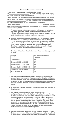


© Copyright 2026