
How To Size A Big Dipper Unit Sizing Big Dipper Systems In
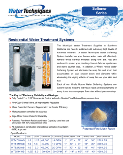
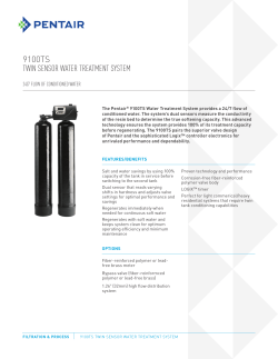
Sizing Big Dipper Systems In Food Service Operations How To Size A Big Dipper® Unit The purpose of this sizing procedure is to give a specifying engineer a simple method for determining the proper size Big Dipper unit for various food service facility applications. Many different methods are in use today by the major code bodies for sizing grease traps. However, the sizing formula utilized by most codes becomes inaccurate whenever the facility contains a large number of fixtures. Using such sizing methods can lead to calculations that indicate enormous flow rates being generated. In reality this rarely occurs because: 1) the building’s potable water supply can not produce this great of a flow rate 2) all of the fixtures can not be in use at the same time, and 3) the only fixtures that can produce high rates of flow are those that “store and release” large volumes of water such as deep multi-compartment sinks. The key factor to be considered when sizing a Big Dipper® Automatic Grease & Oils Removal Unit is the peak flow rate*. The method shown on the sizing page takes the most commonly used sizing method and adapts it for use in single fixture service applications. An example of a single fixture is a two or three compartment sink. An individual Big Dipper unit could be plumbed to this type of fixture. The multiple fixture sizing formula takes points 1, 2 and 3 above into consideration. As an illustration, the multiple fixture example describes common kitchen wash equipment and drainage requirements for a typical large full-service restaurant. Using the older multiple fixture unit values, the peak flow rate is calculated to be 240 gallons per minute (14.14 l/s). Using field experience data and the combined method, we find that the peak flow rate for this “typical” restaurant is actually 48 gallons per minute. At 48 gallons per minute (3.03 l/s) maximum peak flow rate, a 50 gallon per minute (3.14 l/s) Big Dipper system could easily handle the effluent discharges of this restaurant. For kitchen effluent flows greater than 50 GPM (3.14 l/s), Big Dipper AST systems should be utilized. Big Dipper AST (Automatic Solids Transfer) centralized grease removal systems are designed for basement locations or for larger, institutionaltype kitchens such as hospitals, correctional facilities or casinos. * Another factor to consider is that of head pressure. Big Dipper internal flow controls are acceptable to 6 feet (1.95 m) of head pressure. If a higher head pressure is present in a location, it is recommended that a larger size Big Dipper unit be installed and the VFCA Flow Control Vent be installed. NOTE: Drawing for reference only. Equipment must be installed in compliance with all applicable laws, regulations and codes, including plumbing codes. Installation should be performed by a qualified plumber. ©2013 Thermaco, Inc. • All rights reserved • Patented/Patents Pending • Specifications subject to change without notice 12/13 646 Greensboro St. • Asheboro, N. C. 27204-2548 • Phone (336) 629-4651 • North America: (800) 633-4204 [email protected] • www.big-dipper.com 1 Sizing Point Source Systems Single Fixture Sizing Suggestions Use this chart to help size Big Dipper equipment that will service a single fixture. Single fixture Big Dipper equipment is designed to sit on the floor beside the fixture it is servicing. For basement installations or installations where the Big Dipper will be more than 6 feet (1.95 m) beneath the fixture it is servicing Thermaco, Inc. recommends the next larger unit be installed as well as installing the VFCA Vented Flow Control Assembly. Consult a licensed plumber regading your specific requirements. Fixture Description Compartment Size Pipe Size GPM Rating Suggested System Sink 1-3* Compartments 18” x 18” x 12”D 2” 20 W-200-IS Sink 1-4* Compartments 18” x 24” x 15”D 2” 25 W-250-IS or W-250-AST Sink 1-4* Compartments 24” x 24” x 15”D 3” 35 W-350-IS Wok Range Wok Range with 1-5 Wok Stations 2” 15 W-150-IS Wok Range Wok Range with 5+ Wok Stations 2” 20 W-200-IS Pre-Rinse Station** N/A W-200-IS Ventilation Hood Use equipment manufacturer’s peak gpm rating Other Fixtures or Appliances Use equipment manufacturer’s peak gpm rating * Recommendations based on standard operating procedure, draining two (2) sinks concurrently. Should three (3) or four (4) sinks be drained concurrently, the supplied flow control will limit flow to unit’s maximum GPM rating. For sewer districts requiring flow ratings based on ASME or PDI standards, contact Thermaco directly for full flow rating assessment. ** Thermaco recommends the use of the FS-1 Flat Strainer or ESU-1 External Strainer Basket in combination with the Big Dipper in pre-rinse areas. Note: To minimize grease/detergent emulsification, plumbing dishwashers directly into the sanitary sewer line is recommended. Consult local codes or a licensed plumber when considering plumbing a dishwasher to a Big Dipper unit. Single Fixture Big Dipper Equipment Model GPM Rating W-200-IS20 W-250-IS & W-250-AST 25 W-350-IS35 W-500-IS50 ©2013 Thermaco, Inc. • All rights reserved • Patented/Patents Pending • Specifications subject to change without notice 2 646 Greensboro St. • Asheboro, N. C. 27204-2548 • Phone (336) 629-4651 • North America: (800) 633-4204 [email protected] • www.big-dipper.com 12/13 Sizing Multiple Fixture Installations Multiple Fixture Sizing Suggestions Use this chart to help size Big Dipper equipment that will service multiple fixtures. Use standard Big Dipper systems for cases where the Big Dipper is less than four feet beneath the fixtures being serviced. For installations where the Big Dipper is servicing multiple fixtures and will be facing more than 6 feet (1.95 m) of head pressure use the next size Big Dipper system or install a Big Dipper AST (Automatic Solids Transfer) Central Grease Removal System. Never install a smaller Big Dipper system than the rated GPM the chart calculates. Consult a licensed plumber regading your specific requirements. Multiple Fixture Flow Calculation: Fixture Floor Drains 3 Compartment sink Pre-rinse Sink Dishwasher* Mop Sink 2 Compartment Sink Hand Sink # Fixtures # # # # # # # Fixture Value (GPM) Total Fixture (GPM) 7.5 25 15 30 15 25 7.5 # x 7.5 # x 25 # x 15 # x 30 # x 15 # x 25 # x 7.5 Averaging Multiplier 0.10 0.25 0.25 0.30 0.25 0.25 0.25 Flow Rating (GPM) # GPM # GPM # GPM # GPM # GPM # GPM # GPM Example: Fixture # Fixtures Fixture Value (GPM) Total Fixture (GPM) Averaging Multiplier Flow Rating (GPM) Floor Drains 12 7.5 90 0.10 9.0 3 Compartment sink 2 25 50 0.25 12.5 Pre-rinse Sink 1 15 15 0.25 3.75 Dishwasher*130300.30 9.0 Mop Sink 1 15 15 0.25 3.75 2 Compartment Sink 1 25 25 0.25 6.25 Hand Sink 2 7.5 15 0.25 3.75 Total 48 gpm Note: Always use next larger size unit than the calculated flow rating. In this case, a W-500-IS system would adequately handle the kitchen flow. *To minimize grease/detergent emulsification, plumbing dishwashers directly into the sanitary sewer line is recommended. Consult local codes or a licensed plumber when considering plumbing a dishwasher to a Big Dipper unit. ** Thermaco recommends the use of the FS-1 Flat Strainer or ESU-1 External Strainer Basket in combination with the Big Dipper in pre-rinse areas. ©2013 Thermaco, Inc. • All rights reserved • Patented/Patents Pending • Specifications subject to change without notice 12/13 646 Greensboro St. • Asheboro, N. C. 27204-2548 • Phone (336) 629-4651 • North America: (800) 633-4204 [email protected] • www.big-dipper.com 3 IS Unit Installation Instructions for High Head Height Situations (6 ft./1.95m) Flow Control Vent/Air Intake (Note: Flow Control Vent may be independent direct connect to atmosphere or code-approved air admittance valve. To be installed above sink flood rim.) NEVER CONNECT TO FACILITY VENT Drainage Piping from Kitchen Installations where head height is greater than 6 feet (1.95 m) Big Dipper VFCA Vented Flow Control Module (Please see Options Section for sizing information) Outlet Vent (Note: Vent may be facility vent connection or code-approved air admittance valve) * Installation in high head height locations requires removal of the Internal Flow Control (small rubber cap under no-hub coupling over the Inlet). Big Dipper® IS Unit Optional P-Trap NOTE: Drawing for reference only. Equipment must be installed in compliance with all applicable laws, regulations and codes, including plumbing codes. Installation should be performed by a qualified plumber. ©2013 Thermaco, Inc. • All rights reserved • Patented/Patents Pending • Specifications subject to change without notice 4 646 Greensboro St. • Asheboro, N. C. 27204-2548 • Phone (336) 629-4651 • North America: (800) 633-4204 [email protected] • www.big-dipper.com 12/13 IS System Plumbing Installation Instructions NOTE: Drawing for reference only. Equipment must be installed in compliance with all applicable laws, regulations and codes, including plumbing codes. Installation should be performed by a qualified plumber. Fill Unit With Water Before Applying To minimize grease build-up in piping, a Big Power Locating the IS Unit Dipper system should be located as close as possible to the fixture it is serving. The system should be visible and easily accessible for maintenance and inspection. The unit must be in a level position. Be sure to check the Specification Sheet for your model for the exact clearances needed for installation. If the system is located directly on the floor, the bottom should be sealed to the floor with an approved silicone type sealant. Make sure the height above the Solids Strainer access cover is enough to remove the strainer assembly. Inlet/Outlet Piping The inlet and outlet piping connections require flexible sleeve pipe couplings. Keep outlet piping as straight as possible. Use only “sweep” connections. Do not reduce the pipe sizing on the outlet piping. Do not install “P” trap on outlet connection of system. (Note: The system already has a internal gas trap). *Note: A P-Trap must be installed between the Big Dipper unit and any upstream facility vent connection Flow Controls Big Dipper systems MUST be filled with water before energizing the power to the system. Failure to do so will result in the destruction of the electric heating element. These elements will NOT be replaced under Thermaco’s Limited Warranty. Venting the Outlet An outlet vent of at least 1/2 the diameter of the system’s outlet or an approved air admittance valve must be present as close as possible to the Big Dipper outlet to prevent possible siphonage problems. Failure to provide a vent for the system voids Thermaco’s Limited Warranty for the system. For High Head Height IS Unit Applications Over 72” (1.95 m) For installations where there is head height of greater than 72” (1.95 meters), Thermaco, Inc. recommends installation of the VFC-1 Vented Flow Control supplied with the unit. Thermaco, Inc. recommends an inlet vent on the piping connection as close a possible to the inlet of the Big Dipper and tied in to the facility vent. Please see Page 4 for installation instructions. Big Dipper systems are equipped with an internal Do Not Use With Food Grinders, Potato flow regulator located inside the inlet end of the system. Verify its location and placement prior Peelers or Waste Disposal Units If the internal solids strainer basket is not used to connecting the inlet piping. or if the system is connected to a Waste Disposal Unit, Garbage Grinder or potato peeler, Thermaco’s Limited Warranty for the system will be void. ©2013 Thermaco, Inc. • All rights reserved • Patented/Patents Pending • Specifications subject to change without notice 12/13 646 Greensboro St. • Asheboro, N. C. 27204-2548 • Phone (336) 629-4651 • North America: (800) 633-4204 [email protected] • www.big-dipper.com 5 AST System Plumbing Installation Instructions NOTE: Drawing for reference only. Equipment must be installed in compliance with all applicable laws, regulations and codes, including plumbing codes. Installation should be performed by a qualified plumber. Locating The AST Unit To minimize grease build-up in piping, a Big Dipper system should be located as close as possible to the fixture it is serving. The system should be visible and easily accessible for maintenance and inspection. The unit must be in a level position. Be sure to check the Specification Sheet for your model for the exact clearances needed for installation. If the system is located directly on the floor, the bottom should be sealed to the floor with an approved silicone type sealant. Make sure the height above the Solids Strainer access cover is enough to remove the strainer assembly. Eductor Pump The facility must provide a minimum 50 PSI water supply to the Eductor pump on the AST system. The eductor pump on the W-250-AST is designed to handle incidental food solids of less than 1” (25 mm) in diameter. The eductor pumps on the W-750-AST & W-1250-AST are designed to handle incidental food solids of less than 1.5” (38 mm) in diameter. Non-food products including rubber, plastic and metal parts cannot be removed by the Eductor. Inlet/Outlet Piping The inlet and outlet piping connections require no-hub type connectors. Keep outlet piping as straight as possible. Assure that outlet pipe has at least a slope of 1/4” per foot. Use only “sweep” connections. Don’t reduce the pipe sizing on the outlet piping. Don’t install “P” trap on outlet connection of system. (Note: The system already has a internal gas trap) Flow Controls Big Dipper systems are equipped with an internal flow regulator located inside the inlet end of the system. Verify its location and placement prior to connecting the inlet piping. If your code requires a vertical type flow regulator, an approved control with a flow rating matching the system’s flow rate should be used. Note: When a Big Dipper is servicing multiple fixtures, some codes require separate flow controls for each fixture. See page for suggested high head height flow regulation installation. Fill Unit With Water Before Applying Power Big Dipper systems MUST be filled with water before energizing the power to the system. Failure to do so will result in the destruction of the electric heating element. These elements will NOT be replaced under Thermaco’s Limited Warranty. Venting the Outlet An outlet vent of at least 1/2 the diameter of the system’s outlet or an approved air admittance valve must be present as close as possible to the Big Dipper outlet to prevent possible siphonage problems. Failure to provide a vent for the system voids Thermaco’s Limited Warranty for the system. Do Not Use With Food Grinders, Potato Peelers or Waste Disposal Units If the system is connected to a Food Disposal or Garbage Grinder, Thermaco’s Limited Warranty will be void. ©2013 Thermaco, Inc. • All rights reserved • Patented/Patents Pending • Specifications subject to change without notice 6 646 Greensboro St. • Asheboro, N. C. 27204-2548 • Phone (336) 629-4651 • North America: (800) 633-4204 [email protected] • www.big-dipper.com 12/13 Internal Strainer (IS) System Electrical Installation Instructions Big Dipper Internal Strainer Series Models utilize one 24 hour time controller*. The timer is located under the hinged lid of the motor enclosure on top of the electrical module of Big Dipper (See Timer Operation Instructions). The Big Dipper should only be plugged into a properly grounded 3-prong 120 VAC outlet. If possible, the power supply outlet for the Big Dipper should be connected to an electrical circuit controlled by a ground fault circuit breaker. Electrical Panel (Not Supplied) 120VAC @ 20 Amps, From Ground Fault Circuit Breaker (Not Supplied) This Big Dipper unit is shipped from the Factory wired for Simultaneous Operation. This means the Heater and Motor operate at the same time under timer control. Continuous Heater Operation is where the Heater is active at all times. To switch to Continuous Heater Operation, switch the RED WIRE on the THERMOSTAT with the BLACK WIRE. (Instructions are on the wiring Diagram in the electrical enclosure.) Note: The Big Dipper unit will not operate when the electrical module is removed. Power Cord, Plugs Into Outlet Duplex Outlet (Not Supplied) PROPERLY DISPOSE OF CONTENTS DAILY *Model W-1250-IS has two (2) timers and two (2) electrical modules NOTE: Drawing for reference only. Equipment must be installed in compliance with all applicable laws, regulations and codes, including electrical codes. Installation should be performed by a qualified electrician. ©2013 Thermaco, Inc. • All rights reserved • Patented/Patents Pending • Specifications subject to change without notice 12/13 646 Greensboro St. • Asheboro, N. C. 27204-2548 • Phone (336) 629-4651 • North America: (800) 633-4204 [email protected] • www.big-dipper.com 7 Automatic Solids Transfer (AST) System Electrical Installation Instructions Electrical Panel (NOT SUPPLIED) 115VAC Circuit, From Ground Fault Circuit Breaker (NOT SUPPLIED) Big Dipper models W-250-AST and W-750-AST are equipped with one (1) 24 Hour/96 Event time controller while the W-1250AST model is equipped with two (2) time controllers. The timer is located under the hinged lid of the motor enclosure on top of the lid of Big Dipper (See Timer Operation Instructions). The Big Dipper should only be plugged into a properly grounded 3 prong 115 VAC outlet. If possible, the power supply outlet for the Big Dipper should be connected to an electrical circuit controlled by a ground fault circuit breaker. This Big Dipper unit is shipped from the Factory wired for Simultaneous Operation. This means the Heater and Motor operate at the same time under timer control. Continuous Heater Operation is where the Heater is active at all times. To switch to Continuous Heater Operation, switch the RED WIRE on the THERMOSTAT with the BLACK WIRE. (Instructions are on the wiring Diagram in the electrical enclosure. Note: The Big Dipper unit will not operate when the electrical module is removed. Duplex Outlet (NOT SUPPLIED) Water Supply Connection Electrical Junction Box on W-750-AST & W-1250-AST (Hidden) Timer* (Under Hinged Lid) PROPERLY DISPOSE OF CONTENTS DAILY *Model W-1250-AST has two (2) timers and two (2) electrical modules NOTE: Drawing for reference only. Equipment must be installed in compliance with all applicable laws, regulations and codes, including electrical codes. Installation should be performed by a qualified electrician. ©2013 Thermaco, Inc. • All rights reserved • Patented/Patents Pending • Specifications subject to change without notice 8 646 Greensboro St. • Asheboro, N. C. 27204-2548 • Phone (336) 629-4651 • North America: (800) 633-4204 [email protected] • www.big-dipper.com 12/13


© Copyright 2026