
AN1136
AN1136
How to Use Widgets in Microchip Graphics Library
Author:
For details about the PIC24F family of microcontrollers,
refer to the “PIC24FJ128GA010 Family Data Sheet”
(DS39747). For details of the Graphic Library API,
please refer to the “Microchip Graphics Library API”
documentation included in the installer of the library.
Paolo Tamayo
Anton Alkhimenok
Microchip Technology Inc.
INTRODUCTION
OVERVIEW OF THE GRAPHICS
LIBRARY
The proliferation of graphical interfaces in ordinary
devices is becoming noticeable. As we go along our
daily activities, more and more products we encounter
have some form of graphical interface. As this feature
becomes a de facto standard, the need to manufacture
these devices at a lower cost becomes apparent. PIC®
microcontrollers, with their reputation for low risk
product development, lower total system cost solution
and faster time to market, makes this realizable. The
free Microchip graphics library makes it very easy to
integrate graphical features in an application. This
application note details how a 16-bit microcontroller
with a graphical library is used to drive a QVGA display
supporting 16-bit colors.
FIGURE 1:
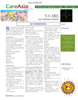
The Microchip Graphics Library was created to cover a
broad range of display device controllers. Targeted for
use with the PIC microcontrollers, it offers an Application Programming Interface (API) that performs rendering of primitive graphics objects as well as advanced
widget-like objects. The library also facilitates easy
integration of input devices through a messaging interface. Applications created using the library will also find
a simple and straightforward process to change display
devices if the need arises. The layered architectural
design of the library makes all of these possible. The
Microchip Graphics Library structure is shown in
Figure 1.
TYPICAL SYSTEM WITH MICROCHIP GRAPHICS LIBRARY
Application Layer
Mouse
Graphics Objects Layer
Draw Function 1
(i.e., 3D Button)
Keypad
Touch Screen
Application
Specific
Message Interface
Draw Function 2
Draw Function N
(i.e., Progress Bar) …
Generic
Modules
Graphics Primitives
Graphics Primitive Functions
(Non-accelerated Line, Circle, Bar, OutText, etc.)
Device Driver Layer
Display Device Driver (DDD)
(i.e., PutPixel, GetPixel)
Graphical Accelerator
(Optional)
Device
Specific
Graphics Display Module
© 2007 Microchip Technology Inc.
DS01136A-page 1
AN1136
The Application Layer is a program that utilizes the
Graphics Library. The Graphics Object Layer (GOL)
renders the widgets, such as Button, Slider, Window,
etc. Throughout this document, widgets will be referred
to as GOL Objects or Objects. To control these Objects,
the GOL layer has a message interface which accepts
messages from the Application Layer. This interface
supports a variety of input devices, such as keyboards,
side buttons, touch screens, mice, etc. The Graphics
Primitive Layer implements the primitive drawing
functions. These functions perform the rendering of
graphics objects, such as Line, Bar, Circle, etc. The
Display Device Driver is the device-dependent layer of
the architecture. This layer talks directly to the display
device controller. For each display controller, a
separate driver should be implemented. This library
comes with a list of display controller drivers already
implemented as part of the Display Device Driver layer.
If the display controller chosen is not in the list, the only
modification needed to use the library will be the
creation or modification of the Display Device Driver.
This scheme allows the library to be portable between
displays. Extensive API allows the application to
access any layer of the library. Drawing and message
processing are handled internally and can be kept
transparent to the application.
The GOL widgets make it easy and fast to create
complex graphics user interfaces. The V1.0 of the
graphics library supports the following:
1.
2.
3.
4.
5.
6.
7.
8.
9.
10.
11.
12.
13.
14.
Button
Slider
Window
Check Box
Radio Button
Edit Box
List Box
Group Box
Horizontal/Vertical Scroll Bars
Progress Bar
Static Text
Picture
Dial
Meter
Please refer to the “Microchip Graphics Library API”
documentation for a description of each Object.
The library also provides two configurations (Blocking
and Non-Blocking), which are set at compile time. For
Blocking configuration, draw functions delay the
execution of programming until drawing is done. For
Non-Blocking configuration, draw functions do not wait
for the drawing completion and release control to the
program. This allows efficient use of microcontroller
time, since the program can perform other tasks instead
of waiting for the drawing tasks to finish rendering. NonBlocking configuration gives advantages in systems
with hardware graphics accelerators and DMA. From
the application point of view, Blocking and Non-Blocking
configuration setting is transparent.
DS01136A-page 2
© 2007 Microchip Technology Inc.
AN1136
Object States
The GOL Objects follow two types of states: the Property States and the Drawing States. Property States
define action and appearance of Objects. Drawing
States, on the other hand, indicate if the Object needs
TABLE 1:
to be hidden, partially redrawn or fully redrawn in the
display. Some common Property States and Drawing
States are shown in Table 1.
Each Object has its own unique Property and Drawing
States. Please refer to the API documentation for
details of each Object’s states.
COMMON OBJECT STATES
State
Type
Description
OBJ_FOCUSED
Property
Object is in the focused state. This is usually used to show selection of the
Object. Not all Objects have this feature.
OBJ_DISABLED
Property
Object is disabled and will ignore all messages.
OBJ_DRAW_FOCUS
Drawing
Focus for the Object should be redrawn.
OBJ_DRAW
Drawing
Object should be redrawn completely.
OBJ_HIDE
Drawing
Object will be hidden by filling the area occupied by the Object with the common
background color. This has the highest priority over all Drawing States. When
an Object is set to be hidden, all other Drawing States are overridden.
Style Scheme
All Objects uses a style scheme structure that defines
the font and colors used. Upon the Object’s creation, a
user-defined style scheme can be assigned to the
TABLE 2:
Object. In the absence of the user-defined scheme, the
default scheme is used. Table 2 summarizes the style
scheme components.
STYLE SCHEME COMPONENTS
Style Component
Description
EmbossDkColor
Dark emboss color used for 3-D effect of Objects.
EmbossLtColor
Light emboss color used for 3-D effect of Objects.
TextColor0
TextColor1
Generic text colors used by the Objects. Usage may vary from one Object to
another.
TextColorDisabled
Text color used for Objects that are disabled.
Color0
Color1
Generic colors used to render Objects. Usage may vary from one Object to
another.
ColorDisabled
Color used to render Objects that are disabled.
CommonBkColor
A common background color of Objects. Typically used to hide Objects from
the screen.
pFont
Pointer to the font used by the Object. Not all Objects use text.
© 2007 Microchip Technology Inc.
DS01136A-page 3
AN1136
TextColorDisabled and ColorDisabled are used when the
Object is in the disabled state. Otherwise, TextColor0,
TextColor1, Color0 and Color1 are used. When the
Object Drawing State is set to hide, the CommonBkColor
is used to fill the area occupied by the Object.
A benefit derived from the use of the style scheme is
that each Object can be assigned a unique style
scheme. Two or more Objects of the same type can
have a unique scheme applied to them. This gives
flexibility in customizing the look and feel of Objects
used from one application to another.
Active Object List
The Graphics Library groups the Objects which are
currently displayed and receiving messages with linked
lists. At any point, GOL messaging and drawing
functions operate on this list. Created Objects are automatically added to the current link list. Only one Object
linked list can be active at a time; it is possible to
maintain multiple lists of Objects. For multiple lists,
applications will be responsible in the management of
switching from one list to another. This scheme allows
applications to treat each list as a display page which
results in an easy management of display pages. Only
the active list will be displayed in the screen. Please
refer to the “Microchip Graphics Library API” for details
on this topic.
Drawing
To render the Objects, the application should call a
draw manager, GOLDraw(). The function parses the
active link list and redraws the Objects with the drawing
states set. When the rendering is completed, drawing
states of the Objects are cleared automatically. The first
created Object will be drawn first. After all Objects in
the current link list are drawn, the GOLDraw() calls the
GOLDrawCallback() function. Custom drawing can
be implemented in this function.
DS01136A-page 4
Messaging
Portability is one of the key features of the library. A
variety of input devices is supported. The library
provides an interface to accept messages from the
input devices. Any input device event is sent to the
library following the GOL message structure. The
structure has the following definition:
EXAMPLE 1:
typedef struct {
BYTE type;
BYTE event;
int param1;
int param2;
} GOL_MSG;
The field type defines the type ID of the input device.
The field event indicates the type of action. Fields, type
and event, will decide how param1 and param2 will be
interpreted. For some cases, only param1 is used, while
in others, both parameter fields will be required.
To illustrate the usage of the GOL_MSG, let us take the
touchscreen module as an example. The GOL_MSG
fields are defined in Table 3.
TABLE 3:
Field
Type
Event
TOUCHSCREEN MESSAGING
DEFINITION
Description
TYPE_TOUCHSCREEN
Possible event IDs are the following:
EVENT_INVALID
EVENT_MOVE
EVENT_PRESS
EVENT_RELEASE
param1 The x-coordinate position of the touch
param2 The y-coordinate position of the touch
When the screen is touched, the application must
populate the message structure and pass it to the library
message handler function, GOLMsg(GOL_MSG* pMsg).
The Object that includes the x,y position will change its
state based on its current state and the event. The custom actions on the input device events can be done in the
GOLMsgCallback() function. The function is called
each time a valid message for some object is received.
© 2007 Microchip Technology Inc.
AN1136
GRAPHICS LIBRARY USAGE
The library is designed to enable seamless integration
of a graphical interface into an application. Using the
already defined Objects requires very minimal coding.
The library provides an API to easily create, manage
and destroy the Objects. Normally, Object behavior is
managed by the library. This is facilitated by the use of
the messaging scheme described earlier. The received
messages are processed, and based on the message
contents, the affected Object’s state is altered. The
library then automatically redraws the Object to show
the change in state.
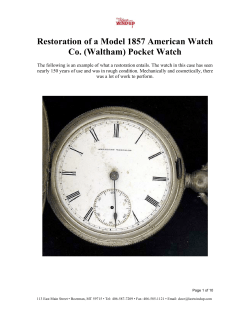
FIGURE 2:
Figure 2 shows a simple flow to use the Graphics
Library. Assuming that the user interface module and
display drivers are chosen and added, minimal coding
will be needed. First, InitGraph() is called to reset
the display device controller, move the cursor position
to (0,0) and initialize the display to all black. Next,
GOLCreateScheme() is called to define the style
scheme to be used for the Objects. If no changes to the
style scheme will be specified, the default style scheme
is used. In this case, the InitGraph() and
GOLCreateScheme() functions can be performed by
just one function call to GOL_Init().
BASIC LIBRARY USAGE FLOW
Initialize Graphics
1
InitGraph()
GOL Init()
Create Style Scheme
Create Objects
Draw Objects
Get User Inputs
Process User Messages
© 2007 Microchip Technology Inc.
2
GolCreateScheme()
3
ObjCreate( , , )
4
GOLDraw()
5
Message Struct
6
GOLMsg()
DS01136A-page 5
AN1136
If a new style scheme is to be created, the following
code can be used as an example to set the colors:
EXAMPLE 2:
GOL_SCHEME* altScheme;
// style scheme
// declare the alternative
altScheme = GOLCreateScheme();
// scheme
altScheme->TextColor0 = BLACK;
altScheme->TextColor1 = BRIGHTBLUE;
// Create alternative style
// set text color 0
// set text color 1
The next step is to create the Objects that will be used.
The ObjCreate( , , ) function represents the multiple Objects that will be created. This can be a single
BtnCreate( , , ) call to create a Button Object or
a series of calls to different Object create functions. For
example, to create three Objects (two Buttons and one
Slider), the following ObjCreate() function calls are
performed:
EXAMPLE 3:
BtnCreate( ID_BTN1,
20, 160, 150, 210,
BTN_DRAW,
NULL,
"LEFT",
NULL);
//
//
//
//
//
//
//
1st Button ID
Object's dimension
set state of the object:
draw the object
no bitmap used
use this text
use default style scheme
BtnCreate( ID_BTN2,
170, 160, 300, 210,
BTN_DRAW,
NULL,
"RIGHT",
NULL);
// 2nd Button ID
SldCreate( ID_SLD1,
20, 105, 300, 150,
SLD_DRAW,
//
//
//
//
//
//
//
//
100,
5,
50,
NULL);
All of these function calls are represented as
ObjCreate() in Figure 2, where Obj represents Btn for
the Buttons and Sld for the Slider. Each Object in the
library has its own ObjCreate() function. These functions return a pointer to the newly created Object. If the
memory allocation for the Object fails, NULL is
returned. If successful, the newly created Object is
automatically added to the linked list described earlier.
DS01136A-page 6
Slider ID
Object's dimension
set state of the object:
draw the object
range
page
initial position
use default style scheme
After the Objects are created, they are drawn by calling
the GOLDraw() function. This function parses the
active Object’s linked list and checks the drawing state
of the Objects. If an Object has a pending drawing state
set, the Object will be redrawn. From the example, the
drawing state for the Button is BTN_DRAW and for the
Slider is SLD_DRAW. After GOLDraw() renders the
Object, it resets the pending drawing state.
© 2007 Microchip Technology Inc.
AN1136
Changes in the state of the Objects can be done through
the input devices, such as keypads, side buttons and
touchscreen. In this example, we assume a touchscreen. The touchscreen module populates the
message structure for any user action on the screen.
This is indicated as a shaded box task (step 5) in the flow
of Figure 2. The message is then processed by the
library with a call to the GOLMsg() function (step 6 in
Figure 2). All objects are parsed to check which one is
affected by the message. The affected Object will
process the message and change its state according to
the indicated action in the message. To show this
change in state, GOLDraw() is again called. This will
render the Object with the new state. Buttons will show
the pressed and released actions when touched while
the slider will slide its thumb when touched and moved.
APPLICATION INTEGRATION
The primary purpose of using graphical interfaces has
always been intended to improve and enhance user
experience on devices. Aside from the additional cool
factor it gives the product, it also provides users additional capabilities and better feedback on the devices
they are operating on. For example, in home security
systems, the keypad can be turned into a touchscreen
display reducing the keys to maybe two (the ON and
OFF button). It does not only eliminate the complicated
keys and primitive character display, it also provides
additional functionality, such as status, setup and settings, which further enhances usage of the system.
Other examples are seen in home automation, industrial
controls and medical devices, where graphical displays
integrate controls of motors, pumps, compressors and
temperature sensors, among others.
FIGURE 3:
How do we integrate controls of these external devices
into the graphical interface? How do we control the
motor speed? How do we implement the numeric keypad? The following sections give a simple procedure to
modify object behavior as well as integrate controls of
external devices. Through the use of the callback functions, we will see how Object behavior can be changed
and set up variables that control external devices.
At this point, we can see that the three Objects are fully
operational with the touchscreen using minimal code. In
some cases, these default Object actions are not
enough for application purposes. The library provides
capability to add advanced Object control and behavior,
as well as integrating these Objects into an application to
control external modules, such as motors or LEDs. This
advanced topic is covered in the next sections.
CUSTOM ACTION ON MESSAGE
In the previous example, it was shown how Objects are
created and drawn using very little code. Using the touch
screen module, the Object’s state can be changed. How
do we use this functioning Object in an application?
Also, how do we change default behavior of the object?
Again, for simplicity, we use the same example and
extend the code to include intermediate manipulation of
the Object states. Assume that the Slider represents a
physical device (i.e., motor speed) that has to be controlled. Also, in addition to the thumb-based control for
the Slider, we want to have two buttons to move the
slider in fixed steps. The “LEFT” Button will move the
Slider’s thumb to the left and the “RIGHT” Button will
move the Slider’s thumb to the right. Since the Slider
was created with a page size of 5, every press of a
Button will increment or decrement the Slider position by
5 units.
CUSTOM ACTION ON MESSAGE EXAMPLE
LEFT
© 2007 Microchip Technology Inc.
RIGHT
DS01136A-page 7
AN1136
To implement this functionality, the message callback
function, GOLMsgCallback(), is used. This callback
function is called by the GOLMsg() function whenever
a valid message is received by the Object.
For example, to press the Button with ID, ID_BTN1, the
user presses the screen location where the Button is
drawn. The user action is detected by the touchscreen
module. The application layer populates the GOL_Msg
structure (Example 1) and calls the message handler
function, GOLMsg().
To process this message, GOLMsg() parses the Objects
list to find which Object was affected and calls the
GOLMsgCallback() function. The application has the
option here to create the custom action on the event or
change to the state of the Object. From coding perspective, the application can decide if GOLMsgCallback()
will return ‘0’ or ‘1’. If ‘1’ is returned, default action will be
TABLE 4:
executed to change the state of the affected Object. If ‘0’
is returned, the application assumes all the changes on
the state of the Object and default action is not
performed. GOLDraw() will render the Object that has
changed its drawing state. In the GOLMsgCallback()
function, the application receives three parameters: raw
GOL message, translated message and pointer to the
Object. The raw GOL message is a pointer to an original
message structure populated by the input device
module. The pointer to the Object affected by the message allows the application to get all of the information
about the Object and control its states. The translated
message is a number returned by the library; it shows
what kind of event happened for the affected Object.
Translated messages are specific to each Object. For
the two Objects used in the demo code, Table 4
summarizes the translated messages.
SLIDER AND BUTTON TRANSLATED MESSAGES
Object
Translated Message
Description
Button
BTN_MSG_PRESSED
BTN-MSG_RELEASED
Sets the current user action on the Button.
Slider
SLD_MSG_INC
SLD_MSG_DEC
These dictate the direction of the movement of the Slider thumb. For
both vertical and horizontal orientation, Sliders can move in the
negative or positive direction.
Note:
Refer to the API documentation for the translated messages of all Objects.
DS01136A-page 8
© 2007 Microchip Technology Inc.
AN1136
Going back to the example, to move the Slider’s thumb
using the Buttons, the code shown below can be
implemented inside the messaging callback function:
EXAMPLE 4:
WORD GOLMsgCallback(WORD objMsg, OBJ_HEADER* pObj, GOL_MSG* pMsg){
WORD objectID;
SLIDER *pSldObj;
}
// get the ID of the object currently being evaluated
objectID = GetObjID(pObj);
// check if message is for 1st Button
if (objectID == ID_BTN1) {
// This message is for 1st Button
// Check if button is pressed
// objMsg is the translated message from the object
if (objMsg == BTN_MSG_PRESSED) {
// Button is pressed decrement the slider position
// Slider pointer is retrieved for slider named ID_SLD1
pSldObj = (SLIDER*)GOLFindObject(ID_SLD1);
// position is decremented by Slider's current page value
SldDecPos(pSldObj);
// set the state to redraw slider thumb to reflect new position
SetState(pSldObj, SLD_DRAW_THUMB);
}
}
// check if message is for 2nd Button
if (objectID == ID_BTN2) {
// This message is for 1st Button
// Check if button is pressed
if (objMsg == BTN_MSG_PRESSED) {
// if button is pressed increment the slider position
// slider pointer is retrieved for slider named ID_SLD1
pSldObj = (SLIDER*)GOLFindObject(ID_SLD1);
// position is incremented by Slider's current page value
SldIncPos(pSldObj);
// set the state to redraw slider thumb to reflect new position
SetState(pSldObj, SLD_DRAW_THUMB);
}
}
// we must return 1 here to update on the buttons (press and release effects)
return 1;
This shows a drawing state change in the Slider. Using
the Buttons, we have altered the behavior of the Slider.
Button 1 decrements the position of the Slider’s thumb
while Button 2 increments the position of the thumb
each time the Buttons are pressed. The draw callback
© 2007 Microchip Technology Inc.
function always returns a ‘1’ to enable the default
actions on the Buttons showing the press and release
effect of the touchscreen and the default action on the
Slider (move thumb to touch area).
DS01136A-page 9
AN1136
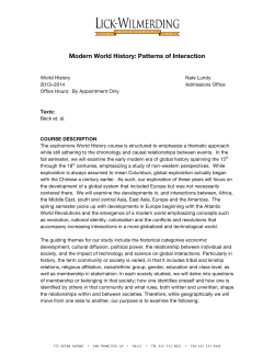
As an example, on the property state change in
Objects, the Button’s behavior is changed when pressing and releasing. Figure 4 shows the changes to the
left Button when pressed. A bitmap is drawn over the
Button’s face and the text, “LEFT”, is moved to the right
to accommodate the bitmap. When released, the bit-
FIGURE 4:
BUTTON CHANGE
LEFT
LEFT
DS01136A-page 10
map goes to the same appearance as shown in
Figure 3. The Button on the right will also exhibit similar
changes to its property when pressed and released. To
implement such property changes, the message
callback function should be modified as shown below:
RIGHT
© 2007 Microchip Technology Inc.
AN1136
EXAMPLE 5:
// bitmap assumed to be declared externally
extern BITMAP_FLASH redRightArrow;
extern BITMAP_FLASH redLeftArrow;
WORD GOLMsgCallback(WORD objMsg, OBJ_HEADER* pObj, GOL_MSG* pMsg){
WORD objectID;
SLIDER *pSldObj;
objectID = GetObjID(pObj);
if (objectID == ID_BTN1) {
if (objMsg == BTN_MSG_PRESSED) {
// set bitmap to show
BtnSetBitmap(pObj, &redLeftArrow);
// set text alignment to right
SetState(pObj, BTN_TEXTRIGHT);
pSldObj = (SLIDER*)GOLFindObject(ID_SLD1);
SldDecPos(pSldObj);
SetState(pSldObj, SLD_DRAW_THUMB);
}
else {
// remove the bitmap
BtnSetBitmap(pObj, NULL);
// place the text back in the middle
ClrState(pObj, BTN_TEXTRIGHT);
}
}
if (objectID == ID_BTN2) {
if (objMsg == BTN_MSG_PRESSED) {
// set bitmap to show
BtnSetBitmap(pObj, &redRightArrow);
// set text alignment to left
SetState(pObj, BTN_TEXTLEFT);
pSldObj = (SLIDER*)GOLFindObject(ID_SLD1);
SldIncPos(pSldObj);
SetState(pSldObj, SLD_DRAW_THUMB);
}
else {
// remove the bitmap
BtnSetBitmap(pObj, NULL);
// place the text back in the middle
ClrState(pObj, BTN_TEXTLEFT);
}
}
return 1;
}
The text alignments of the two Buttons are moved to
the left and to the right whenever they are pressed. This
changes the property state of the Buttons. Additionally,
© 2007 Microchip Technology Inc.
the Buttons show bitmaps of red arrows whenever they
are pressed. (See Example A-2 in Appendix A:
“Source Code” for details.)
DS01136A-page 11
AN1136
Custom Drawing
In some cases, it is also necessary to add customized
drawings on the screen. This is usually added to
implement rendering of graphics that are otherwise not
covered by the library Objects. An example would be
animation using a series of bitmaps or simple graphics
to indicate some system variables in the application. An
important note in rendering customized graphics is to
ensure that the drawing of library Objects should not
conflict with the customized drawing. Some drawing
parameters, such as current color used, line type, line
size, graphic cursor location and clipping regions, may
be set when GOLDraw() is rendering objects. If custom graphics set these parameters while some Objects
are still being drawn, this may result in Objects not rendered properly. The library provides opportunity for the
application to perform this customized rendering. This
must be implemented in the GOLDrawCallback()
function.
FIGURE 5:
Going back to our example, let us assume there is an
additional graphical Object that is application-defined.
This Object will be a level control represented by a series
of bars. As the value of the Slider increases (position of
the thumb goes to the right), bars are drawn to represent
the value. When the Slider value decreases (thumb
moves to the left), bars are erased accordingly. Figure 5
illustrates this user-defined graphical Object.
SLIDER CONTROLLED USER-DEFINED OBJECT
Using the GOLDrawCallback() function will ensure
that the rendering of the user Object will be clean without
interference from the drawing performed by the library.
DS01136A-page 12
When all Objects in the active link list are drawn,
GOLDraw() calls GOLDrawCallback(). Inside this
function, color, clipping region, line types and graphic
display cursor can be modified by the custom drawings.
The callback function has the option to return the drawing control to GOLDraw(). If the callback returns a ‘0’,
drawing of GOL Objects in the active list is suspended.
If a ‘1’ is returned, GOLDraw() resumes in checking for
state change in the Objects in the active lists and
renders the Objects that need to be updated.
To draw the level control, the GOLDrawCallback()
function is modified to contain the following code:
© 2007 Microchip Technology Inc.
AN1136
EXAMPLE 6:
WORD value, y, x;// variables for the slider position
static WORD prevValue = 0;// maintains the previous value of the Slider
if (update) {
/* User defined graphics:
This draws a series of bars indicating the value/position of the
slider's thumb. The height of the bars follows the equation of a
parabola "(y-k)^2 = 4a(x-h) with vertex at (k, h) at (60,100) on
the display. The value 110 is the 4*a constant. x & y are calculated
based on the value of the slider thumb. The bars are drawn from
60 to 260 in the x-axis and 10 to 100 in the y-axis. Bars are drawn
every 6 pixels with width of 4 pixels.
Only the bars that are added or removed are drawn. This may require
extra computation. However, it results in significant less data movement.
Thus resulting in an overall efficient customized drawing.
*/
// check the value of slider
value = SldGetPos(pSld);
// remove bars if there the new value is less
// than the previous
SetColor(BLACK)
if (value < prevValue) {
while (prevValue > value) {
// get the height of the bar to be removed
y = (prevValue*prevValue)/110;
// bars are drawn every 6 pixels with width = 4 pixels.
x = (prevValue*2);
x = x - (x%6);
// draw a BLACK colored bar to remove the current bar drawn
Bar(x+60,100-y, x+64,100);
// decrement by three since we are drawing every 6 pixels
prevValue -= 3;
}
}
// Draw bars if there the new value is greater
// than the previous
else {
while (prevValue < value) {
// set the color of the bar drawn
if (prevValue < 60) {
SetColor(BRIGHTGREEN);
} else if ((prevValue < 80) && (prevValue >= 60)) {
SetColor(BRIGHTYELLOW);
} else if (prevValue >= 80) {
SetColor(BRIGHTRED);
}
// get the height of the bar to be drawn
y = (prevValue*prevValue)/110;
// bars are drawn every 6 pixels with width = 4 pixels.
x = (prevValue*2);
x = x - (x%6);
// draw a bar to show increase in value
Bar(x+60,100-y, x+64,100);
// increment by three since we are drawing every 6 pixels
prevValue += 3;
}
}
// prevValue will have the current value after drawing or removing bars.
// reset the update flag
update = 0;
}
return 1;
}
© 2007 Microchip Technology Inc.
DS01136A-page 13
AN1136
The main code is also modified to add the initialization
of the new global Slider Pointer.
EXAMPLE 7:
// Global variable declarations
SLIDER *pSld;
WORD update;
// global Slider pointer
// global variable for
// graphics update flag
// modification in slider creation in main and initialization of
// user graphics update flag
pSld = SldCreate(ID_SLD1,
// Slider ID
20, 105, 300, 150,
// Object's dimension
SLD_DRAW,
// set state of the object:
//
draw the object
100,
// range
5,
// page
50,
// initial position
NULL);
// use default style scheme
update = 1;
// to initialize the user
// graphics update flag
The global variable, update, is added to refresh the bar
graphics only when necessary (when the Buttons are
pressed or the Slider is moved). This makes the
drawing callback function immediately return a ‘1’ when
there are no Objects in the screen affected by the
messages. The complete code listing for this example
is shown in Example A-3 in Appendix A: “Source
Code”.
DS01136A-page 14
Compile-Time Options
The library provides compile-time options that may affect
application or system requirements. To save on program
memory, some of the unused code may be removed. For
example, unused widgets or input devices can be
removed (touchscreen, keypad, etc.). If some hardware
accelerator is present in the display controller, it can be
used by modifying the driver code and disabling the
primitive layer code. Please refer to the “Microchip
Graphics Library API” documentation for details on the
compile-time options.
© 2007 Microchip Technology Inc.
AN1136
PROJECT FILES
CONCLUSION
For the complete listing of the project files and directory
structure, please refer to Microchip graphics library
available at www.microchip.com/graphics. Installation
of the library will include the examples given in this
application note. The directory structure of the installed
library will be similar to the following:
The Microchip Graphics Library is a free graphics library
available for PIC microcontroller. It provides ready to use
Objects for applications requiring widget-type control in
their interfaces. Its architecture makes the library independent on the display hardware used and requires only
a creation or modification of one device driver file. This
facilitates an easy migration from one display device to
another. The implementation of the messaging scheme
also provides easy integration of a variety of input
devices. Developers wanting to integrate graphical interfaces to their application will surely see how this library
can hasten time to market of their product using PIC
microcontrollers.
Microchip Solutions
AN1136 Demo
Microchip
Graphics
Documents
Utilities
Include
Graphics
Where the subdirectory, “AN1136 Demo”, will contain
the source code of the demo application described in
this document. This directory can be the project
directory where application code can be added and
compiled with the library. “Microchip” subdirectory
contains the library components. The “Graphics” subdirectory is where the C files, documentation and
utilities are located. The “Include” subdirectory contains
the “Graphics” subdirectory with the library header files.
All subdirectories and files under the “Microchip”
directory should not be modified. In case your project
will use more than one Microchip library solution, this
directory will contain all the library files you install.
Thus, it is important to maintain the files in this
directory.
The “Microchip Solution” directory may become your
MyProjects directory that will contain all your projects
using the different Microchip solutions.
© 2007 Microchip Technology Inc.
DS01136A-page 15
AN1136
APPENDIX A:
A.1
SOURCE CODE
Examples
The following examples show how the Microchip Graphics Library routines are used in an application.
A.1.1
EXAMPLE 1
This example shows a very simple usage of the GOL Objects of the library. It creates three Objects and draws them
accordingly. A touchscreen interface is assumed that supplies the user action on the Objects. It assumes that all other
header files needed by the library have been included in the project.
DS01136A-page 16
© 2007 Microchip Technology Inc.
AN1136
EXAMPLE A-1:
/*******************************************************************/
/*******************************************************************/
#define ID_BTN1 10
#define ID_BTN211
#define ID_SLD112
GOL_SCHEME* altScheme;
int main(void){
GOL_MSG msg;
TouchInit();
GOLInit();
altScheme = GOLCreateScheme();
altScheme->TextColor0 = BLACK;
altScheme->TextColor1 = BRIGHTBLUE;
BtnCreate( ID_BTN1,
20, 160, 150, 210,
BTN_DRAW,
NULL,
"LEFT",
NULL);
// declare the alternative
// style scheme
// GOL message structure to
// interact with GOL
// Initialize touch screen
// Initialize graphics library &
// create default style scheme for GOL
//
//
//
//
Create alternative style
scheme
set text color 0
set text color 1
//
//
//
//
//
//
//
1st Button ID
Object's dimension
set state of the object:
draw the object
no bitmap used
use this text
use default style scheme
BtnCreate( ID_BTN2,
170, 160, 300, 210,
BTN_DRAW,
NULL,
"RIGHT",
NULL);
// 2nd Button ID
SldCreate( ID_SLD1,
20, 105, 300, 150,
SLD_DRAW,
//
//
//
//
//
//
//
//
Slider ID
Object's dimension
set state of the object:
draw the object
range
page
initial position
use default style scheme
//
//
//
//
Draw GOL object
Get message from
touch screen
Process message
100,
5,
50,
NULL);
while(1){
if (GOLDraw()){
TouchGetMsg(&msg);
GOLMsg(&msg);
}
}
}
// Call back functions must be defined and return a value of 1
// even though they are not used
WORD GOLMsgCallback(WORD objMsg, OBJ_HEADER* pObj, GOL_MSG* pMsg){
return 1;
}
WORD GOLDrawCallback(){
return 1;
}
© 2007 Microchip Technology Inc.
DS01136A-page 17
AN1136
A.1.2
EXAMPLE 2
This example is a modification of the GOLMsgCallback() function of Example A-1, where the Slider’s thumb
movement can also be controlled by the two Buttons and it displays the image when the Button is pressed.
EXAMPLE A-2:
/*******************************************************************/
/*******************************************************************/
// bitmap assumed to be declared externally
extern BITMAP_FLASH redRightArrow;
extern BITMAP_FLASH redLeftArrow;
WORD GOLMsgCallback(WORD objMsg, OBJ_HEADER* pObj, GOL_MSG* pMsg){
WORD objectID;
SLIDER *pSldObj;
objectID = GetObjID(pObj);
if (objectID == ID_BTN1) {
if (objMsg == BTN_MSG_PRESSED) {
// set bitmap to show
BtnSetBitmap(pObj, &redLeftArrow);
// move the text to the right
SetState(pObj, BTN_TEXTRIGHT);
pSldObj = (SLIDER*)GOLFindObject(ID_SLD1);
SldDecPos(pSldObj);
SetState(pSldObj, SLD_DRAW_THUMB);
}
else {
// remove the bitmap
BtnSetBitmap(pObj, NULL);
// place the text back in the middle
ClrState(pObj, BTN_TEXTRIGHT);
}
}
if (objectID == ID_BTN2) {
if (objMsg == BTN_MSG_PRESSED) {
// set bitmap to show
BtnSetBitmap(pObj, &redRightArrow);
// move the text to the left
SetState(pObj, BTN_TEXTLEFT);
pSldObj = (SLIDER*)GOLFindObject(ID_SLD1);
SldIncPos(pSldObj);
SetState(pSldObj, SLD_DRAW_THUMB);
}
else {
// remove the bitmap
BtnSetBitmap(pObj, NULL);
// place the text back in the middle
ClrState(pObj, BTN_TEXTLEFT);
}
}
return 1;
}
DS01136A-page 18
© 2007 Microchip Technology Inc.
AN1136
A.1.3
EXAMPLE 3
This example is a modification of the GOLDrawCallback() function of Example A-1, where the Slider’s thumb
movement controls the drawing of a user-defined graphic that represents a level value. The message callback function
is the same as Example A-2.
EXAMPLE A-3:
/*******************************************************************/
/*******************************************************************/
#define ID_BTN1
#define ID_BTN2
#define ID_SLD1
10
11
12
// bitmap assumed to be declared externally
extern BITMAP_FLASH redRightArrow;
extern BITMAP_FLASH redLeftArrow;
GOL_SCHEME* altScheme;
// declare the alternative
// style scheme
// Global variable declarations
SLIDER *pSld;
WORD update;
int main(void){
GOL_MSG msg;
// global Slider pointer
// global variable for
// graphics update flag
// GOL message structure to
// interact with GOL
TouchInit();
GOLInit();
// Initialize touch screen
// Initialize graphics library &
// create default style scheme for GOL
altScheme = GOLCreateScheme();
altScheme->TextColor0 = BLACK;
altScheme->TextColor1 = BRIGHTBLUE;
BtnCreate(
ID_BTN1,
20, 160, 150, 210,
BTN_DRAW,
NULL,
"LEFT",
NULL);
//
//
//
//
Create alternative style
scheme
set text color 0
set text color 1
//
//
//
//
//
//
//
1st Button ID
Object's dimension
set state of the object:
draw the object
no bitmap used
use this text
use default style scheme
BtnCreate(
ID_BTN1,
170, 160, 300, 210,
BTN_DRAW,
NULL,
"RIGHT",
NULL);
// 2nd Button ID
pSld = SldCreate(
ID_SLD1,
20, 105, 300, 150,
SLD_DRAW,
//
//
//
//
//
//
//
//
100,
5,
50,
NULL);
update = 1;
Slider ID
Object's dimension
set state of the object:
draw the object
range
page
initial position
use default style scheme
// to initialize the user
// graphics update flag
while(1){
if (GOLDraw()) {
TouchGetMsg(&msg);
GOLMsg(&msg);
//
//
//
//
Draw GOL object
Get message from
touch screen
Process message
}
}
}
© 2007 Microchip Technology Inc.
DS01136A-page 19
AN1136
EXAMPLE A-3:
(CONTINUED)
WORD GOLDrawCallback(){
WORD value, y, x;// variables for the slider position
static WORD prevValue = 0;// maintains the previous value of the Slider
if (update) {
/* User defined graphics:
This draws a series of bars indicating the value/position of the
slider's thumb. The height of the bars follows the equation of a
parabola "(y-k)^2 = 4a(x-h) with vertex at (k, h) at (60,100) on
the display. The value 110 is the 4*a constant. x & y are calculated
based on the value of the slider thumb. The bars are drawn from
60 to 260 in the x-axis and 10 to 100 in the y-axis. Bars are drawn
every 6 pixels with width of 4 pixels.
Only the bars that are added or removed are drawn. This may require
extra computation. However, it results in significant less data movement.
Thus resulting in an overall efficient customized drawing.
*/
// check the value of slider
value = SldGetPos(pSld);
// remove bars if there the new value is less
// than the previous
SetColor(BLACK)
if (value < prevValue) {
while (prevValue > value) {
// get the height of the bar to be removed
y = (prevValue*prevValue)/110;
// bars are drawn every 6 pixels with width = 4 pixels.
x = (prevValue*2);
x = x - (x%6);
// draw a BLACK colored bar to remove the current bar drawn
Bar(x+60,100-y, x+64,100);
// decrement by three since we are drawing every 6 pixels
prevValue -= 3;
}
}
// Draw bars if there the new value is greater
// than the previous
else {
while (prevValue < value) {
// set the color of the bar drawn
if (prevValue < 60) {
SetColor(BRIGHTGREEN);
} else if ((prevValue < 80) && (prevValue >= 60)) {
SetColor(BRIGHTYELLOW);
} else if (prevValue >= 80) {
SetColor(BRIGHTRED);
}
// get the height of the bar to be drawn
y = (prevValue*prevValue)/110;
// bars are drawn every 6 pixels with width = 4 pixels.
x = (prevValue*2);
x = x - (x%6);
// draw a bar to show increase in value
Bar(x+60,100-y, x+64,100);
// increment by three since we are drawing every 6 pixels
prevValue += 3;
}
}
}
// prevValue will have the current value after drawing or removing bars.
// reset the update flag
update = 0;
}
return 1;
}
DS01136A-page 20
© 2007 Microchip Technology Inc.
Note the following details of the code protection feature on Microchip devices:
•
Microchip products meet the specification contained in their particular Microchip Data Sheet.
•
Microchip believes that its family of products is one of the most secure families of its kind on the market today, when used in the
intended manner and under normal conditions.
•
There are dishonest and possibly illegal methods used to breach the code protection feature. All of these methods, to our
knowledge, require using the Microchip products in a manner outside the operating specifications contained in Microchip’s Data
Sheets. Most likely, the person doing so is engaged in theft of intellectual property.
•
Microchip is willing to work with the customer who is concerned about the integrity of their code.
•
Neither Microchip nor any other semiconductor manufacturer can guarantee the security of their code. Code protection does not
mean that we are guaranteeing the product as “unbreakable.”
Code protection is constantly evolving. We at Microchip are committed to continuously improving the code protection features of our
products. Attempts to break Microchip’s code protection feature may be a violation of the Digital Millennium Copyright Act. If such acts
allow unauthorized access to your software or other copyrighted work, you may have a right to sue for relief under that Act.
Information contained in this publication regarding device
applications and the like is provided only for your convenience
and may be superseded by updates. It is your responsibility to
ensure that your application meets with your specifications.
MICROCHIP MAKES NO REPRESENTATIONS OR
WARRANTIES OF ANY KIND WHETHER EXPRESS OR
IMPLIED, WRITTEN OR ORAL, STATUTORY OR
OTHERWISE, RELATED TO THE INFORMATION,
INCLUDING BUT NOT LIMITED TO ITS CONDITION,
QUALITY, PERFORMANCE, MERCHANTABILITY OR
FITNESS FOR PURPOSE. Microchip disclaims all liability
arising from this information and its use. Use of Microchip
devices in life support and/or safety applications is entirely at
the buyer’s risk, and the buyer agrees to defend, indemnify and
hold harmless Microchip from any and all damages, claims,
suits, or expenses resulting from such use. No licenses are
conveyed, implicitly or otherwise, under any Microchip
intellectual property rights.
Trademarks
The Microchip name and logo, the Microchip logo, Accuron,
dsPIC, KEELOQ, KEELOQ logo, microID, MPLAB, PIC,
PICmicro, PICSTART, PRO MATE, rfPIC and SmartShunt are
registered trademarks of Microchip Technology Incorporated
in the U.S.A. and other countries.
AmpLab, FilterLab, Linear Active Thermistor, Migratable
Memory, MXDEV, MXLAB, SEEVAL, SmartSensor and The
Embedded Control Solutions Company are registered
trademarks of Microchip Technology Incorporated in the
U.S.A.
Analog-for-the-Digital Age, Application Maestro, CodeGuard,
dsPICDEM, dsPICDEM.net, dsPICworks, dsSPEAK, ECAN,
ECONOMONITOR, FanSense, FlexROM, fuzzyLAB,
In-Circuit Serial Programming, ICSP, ICEPIC, Mindi, MiWi,
MPASM, MPLAB Certified logo, MPLIB, MPLINK, PICkit,
PICDEM, PICDEM.net, PICLAB, PICtail, PowerCal,
PowerInfo, PowerMate, PowerTool, REAL ICE, rfLAB, Select
Mode, Smart Serial, SmartTel, Total Endurance, UNI/O,
WiperLock and ZENA are trademarks of Microchip
Technology Incorporated in the U.S.A. and other countries.
SQTP is a service mark of Microchip Technology Incorporated
in the U.S.A.
All other trademarks mentioned herein are property of their
respective companies.
© 2007, Microchip Technology Incorporated, Printed in the
U.S.A., All Rights Reserved.
Printed on recycled paper.
Microchip received ISO/TS-16949:2002 certification for its worldwide
headquarters, design and wafer fabrication facilities in Chandler and
Tempe, Arizona; Gresham, Oregon and design centers in California
and India. The Company’s quality system processes and procedures
are for its PIC® MCUs and dsPIC® DSCs, KEELOQ® code hopping
devices, Serial EEPROMs, microperipherals, nonvolatile memory and
analog products. In addition, Microchip’s quality system for the design
and manufacture of development systems is ISO 9001:2000 certified.
© 2007 Microchip Technology Inc.
DS01136A-page 21
WORLDWIDE SALES AND SERVICE
AMERICAS
ASIA/PACIFIC
ASIA/PACIFIC
EUROPE
Corporate Office
2355 West Chandler Blvd.
Chandler, AZ 85224-6199
Tel: 480-792-7200
Fax: 480-792-7277
Technical Support:
http://support.microchip.com
Web Address:
www.microchip.com
Asia Pacific Office
Suites 3707-14, 37th Floor
Tower 6, The Gateway
Harbour City, Kowloon
Hong Kong
Tel: 852-2401-1200
Fax: 852-2401-3431
India - Bangalore
Tel: 91-80-4182-8400
Fax: 91-80-4182-8422
India - New Delhi
Tel: 91-11-4160-8631
Fax: 91-11-4160-8632
Austria - Wels
Tel: 43-7242-2244-39
Fax: 43-7242-2244-393
Denmark - Copenhagen
Tel: 45-4450-2828
Fax: 45-4485-2829
India - Pune
Tel: 91-20-2566-1512
Fax: 91-20-2566-1513
France - Paris
Tel: 33-1-69-53-63-20
Fax: 33-1-69-30-90-79
Japan - Yokohama
Tel: 81-45-471- 6166
Fax: 81-45-471-6122
Germany - Munich
Tel: 49-89-627-144-0
Fax: 49-89-627-144-44
Atlanta
Duluth, GA
Tel: 678-957-9614
Fax: 678-957-1455
Boston
Westborough, MA
Tel: 774-760-0087
Fax: 774-760-0088
Chicago
Itasca, IL
Tel: 630-285-0071
Fax: 630-285-0075
Dallas
Addison, TX
Tel: 972-818-7423
Fax: 972-818-2924
Detroit
Farmington Hills, MI
Tel: 248-538-2250
Fax: 248-538-2260
Kokomo
Kokomo, IN
Tel: 765-864-8360
Fax: 765-864-8387
Los Angeles
Mission Viejo, CA
Tel: 949-462-9523
Fax: 949-462-9608
Santa Clara
Santa Clara, CA
Tel: 408-961-6444
Fax: 408-961-6445
Toronto
Mississauga, Ontario,
Canada
Tel: 905-673-0699
Fax: 905-673-6509
Australia - Sydney
Tel: 61-2-9868-6733
Fax: 61-2-9868-6755
China - Beijing
Tel: 86-10-8528-2100
Fax: 86-10-8528-2104
China - Chengdu
Tel: 86-28-8665-5511
Fax: 86-28-8665-7889
Korea - Daegu
Tel: 82-53-744-4301
Fax: 82-53-744-4302
China - Fuzhou
Tel: 86-591-8750-3506
Fax: 86-591-8750-3521
Korea - Seoul
Tel: 82-2-554-7200
Fax: 82-2-558-5932 or
82-2-558-5934
China - Hong Kong SAR
Tel: 852-2401-1200
Fax: 852-2401-3431
Malaysia - Kuala Lumpur
Tel: 60-3-6201-9857
Fax: 60-3-6201-9859
China - Nanjing
Tel: 86-25-8473-2460
Fax: 86-25-8473-2470
Malaysia - Penang
Tel: 60-4-227-8870
Fax: 60-4-227-4068
China - Qingdao
Tel: 86-532-8502-7355
Fax: 86-532-8502-7205
Philippines - Manila
Tel: 63-2-634-9065
Fax: 63-2-634-9069
China - Shanghai
Tel: 86-21-5407-5533
Fax: 86-21-5407-5066
Singapore
Tel: 65-6334-8870
Fax: 65-6334-8850
China - Shenyang
Tel: 86-24-2334-2829
Fax: 86-24-2334-2393
Taiwan - Hsin Chu
Tel: 886-3-572-9526
Fax: 886-3-572-6459
China - Shenzhen
Tel: 86-755-8203-2660
Fax: 86-755-8203-1760
Taiwan - Kaohsiung
Tel: 886-7-536-4818
Fax: 886-7-536-4803
China - Shunde
Tel: 86-757-2839-5507
Fax: 86-757-2839-5571
Taiwan - Taipei
Tel: 886-2-2500-6610
Fax: 886-2-2508-0102
China - Wuhan
Tel: 86-27-5980-5300
Fax: 86-27-5980-5118
Thailand - Bangkok
Tel: 66-2-694-1351
Fax: 66-2-694-1350
Italy - Milan
Tel: 39-0331-742611
Fax: 39-0331-466781
Netherlands - Drunen
Tel: 31-416-690399
Fax: 31-416-690340
Spain - Madrid
Tel: 34-91-708-08-90
Fax: 34-91-708-08-91
UK - Wokingham
Tel: 44-118-921-5869
Fax: 44-118-921-5820
China - Xian
Tel: 86-29-8833-7252
Fax: 86-29-8833-7256
10/05/07
DS01136A-page 22
© 2007 Microchip Technology Inc.


© Copyright 2026