
How to make Sodium Perchlorate
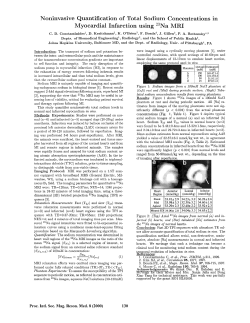
How to make Sodium Perchlorate
(This is a compilation from different websites that has been edited for grammar and added to for
clarity)
Sodium Perchlorate is not used in pyrotechnics due to the fact that it is hygroscopic. It has three
hydrates containing 0, 1 and 2 water molecules. It is used to make Ammonium or Potassium
Perchlorate and other Perchlorates by double decomposition.
There are two routes you can take when making Sodium Perchlorate.
You can start with Sodium Chloride and let the cell run and run until the cell turns from a Chlorate
cell into a Perchlorate cell. You can top up the cell with either water or NaCl solution when the cell is a
Chlorate cell. This is what is done in US patent 3,493,478. A 0.3% solution of Methylene Blue can be
very useful here, as you can tell when your cell has become a Perchlorate cell by testing a sample of
the cell with the Methylene Blue solution. When it has turned into a Perchlorate cell you can run the
cell for the appropriate amount of time in order to convert the Chlorate (+ the 10% Chloride) into
Perchlorate. It is generally agreed that Perchlorate will start to form when the NaCl is at a
concentration of about 10% in the cell. You need a Lead Dioxide anode. Using Platinum anodes is not
advisable for this method as there wear rate will be excessive when the Chloride concentration gets
low and when the Chlorate concentration gets low.
The other route is to start off with solid Sodium Chlorate and dissolve it in water to make a 50%(wt)
solution (that's approx. 720g Chlorate per liter of solution) of Chlorate and run it for the amount of
time recommended in the run time section or until the Chlorate concentration is low.
Anode materials
The Anode materials for making Perchlorate are more limited than Chlorate making.
Lead Dioxide, Platinum, Manganese Dioxide(high wear, US Patent No. 4,072,586) and possibly some
types of MMO.
Graphite will NOT make Perchlorate without huge amounts of wear (totally impractical). It can be
used in cells that contain a diaphragm according to US Pat. 1,279,593.
Cathode materials
Cathode materials can be SS, Graphite, mild Steel, Nickel and Titanium. Phosphor Bronze has been
used by industry.
When mild steel and Nickel is used, Chromate's are desirable to stop the Cathode from being attacked
by the Hypochlorous acid in the cell electrolyte. (0.5 to 5 grams/Liter). Chromates also increase current
efficiency by stopping reduction at the cathode (the conversion of Chlorate and Hypochlorite to
Chloride).
Chromate's are not compatible with Lead Dioxide. Use Titanium as a cathode if you can get it.
Sodium Fluoride or a Persulphate may also be used to stop Chlorate or Hypochlorite being converted
(reduced) back into Chloride at the Cathode.
When using Platinum as an Anode it's wear rate will increase as the Chlorate concentration decreases,
and below 50g/l it may be excessive, high temperatures also increase it's wear rate. Wear rates from
manufacturers have been reported as 3 to 6 grams Pt per ton Sodium Perchlorate.
The concentration of Chlorate should be kept above 100g/l if a high current efficiency is desirable. (The
Perchlorates. Schumacher J.C. P86)
The temperature of the cell is usually maintained at about 30 to 60oC. The current density on the
Anode is usually much greater than with Sodium Chlorate manufacture, and high current density's do
not decrease current efficiency. Typical Anode current densities are from 150 to 400mA per square cm
for Lead Dioxide anodes and 200 to 500mA per square cm for Platinum. Most commercial plants use
water circulation through coils in the cell for to remove heat generated in the cell to stop it from
overheating. The amateur can keep the cell cool by putting it sitting in a large tub of water or by
keeping the current per volume low at about one amp per 100ml of solution.
The voltage across a Perchlorate cell is higher than a Chlorate cell and will be in the range of about 4
to 6.5 volts.
The cost of electrical power for to make one Kg of Na Perchlorate from Na Chlorate is about two KWh
(two "unit's" of power) which is approx. 18 US cents.
To start your cell about 700grams Na Chlorate are dissolved in some water and more water added to
make one liter (A solution of Sodium Chlorate containing 700g/l has a density of 1.428 and is 49%(wt)
Sodium Chlorate, see Graphs and table's in the Sodium Chlorate section).
Dichromate, Fluoride (Na, K, or Hydrofluoric acid) or some Persulphate (Na, or K) or both F and the
Persulphate is added to the cell for to improve the current efficiency. About 2 g/l Sodium fluoride or
about 2g/l of K Persulphate is OK. If using Dichromate use 2 to 4 grams per liter.
The current is turned on and the cell is run for the appropriate time as outlined in the run time section.
The product is then either turned into K or Ammonium Perchlorate (see relevant section) or solid
Sodium Perchlorate is extracted and the mother liquor is returned to the cell for the next run of the cell.
All mother liquor should always be returned to the cell as it will be rich in Chlorate and Perchlorate
because of their high solubility. Note that Platinum Anodes will corrode if used to reduce the Chlorate
concentration to a very low value. You need Lead Dioxide if you wish to run a cell from Chloride to
Chlorate to Perchlorate to Low Chlorate concentration, without stopping.
There is a good description of a Perchlorate cell using a Platinum wire anode at the bottom of this page
by GarageChemist. In his cell you must use Dichromates to stop Chloride from forming in the cell and
you must start the cell with zero (thats 0.00%), Chloride in the electrolyte to avoid Platinum anode
erosion.
SMALL amounts of Chloride in the cell are a Platinum anode killer.
Since Sodium Perchlorate has a number of hydrates this will need to be noted if yields are being
calculated. Reduce all product to the anhydrous state. Which hydrate forms depends on the solution
concentration and temperature as your product crystallizes.
Run time for a Sodium Perchlorate cell
Run time for Sodium Perchlorate cell
The current efficiency for a Perchlorate cell is not pH dependent and the electrolyte will drift alkaline.
Efficiency increases as the current density on the anode increases and decreases as the amount of
Chlorate in the solution decreases. You will generally get higher current efficiency's for a Perchlorate
cell than for a Chlorate cell. The current efficiency will be of the order of about 80%, especially if you
use an additive like Fluorine and run your cell at a high anode current density of about 350mA per cm
squared. This, together with the fact that it only takes two moles (as opposed to 6 moles for Chloride to
Chlorate) of electrons to make one mole of Perchlorate from one mole of Chlorate, gives Perchlorate
cells (pleasantly) surprising short run times.
In order to make one Chlorate molecule into one Perchlorate molecule you must move one oxygen
atom from water to the Chlorate. This takes two electrons. Another way of saying this, is that it takes
two moles of electrons (26.8 Ah * 2) to make one mole of Perchlorate out of one mole of Chlorate.
The overall reaction equation is: NaClO3 + H2O + two electrons ===> NaClO4 + H2 gas
The actual mechanisms are not fully agreed and can be further investigated in J. of Applied
ElectroChem. 17 (1987) 33 - 48 and also Comprehensive Treatise of Electrochemistry Vol. 2 (see
further reading section).
The Chlorate concentration at which the current efficiency starts to decline is not fully agreed in the
literature. There are a lot of variables that effect the point at where the low Chlorate concentration
effects current efficiency. I have assumed that it is effected at about 100g/l Chlorate which is roughly
where it happens in a fairly typical cell.
1 Mole Na Chlorate = 106.45g (+16 grams for Na Perchlorate)
Run time in minutes per gram of NaClO3 for 50% and 80% current efficiency's
(no Chloride present in the cell at start, additives used, F or Persulphate)
Amps
50% current efficiency
Chlorate level below about 5g/l
(at the end of the run)
80% current efficiency
Chlorate levels above 100g/l
(at the end of the run)
2
30.19
16.23
4
15.09
8.11
8
7.54
4.05
10
6.03
3.24
15
4.02
2.16
20
3.01
1.62
30
2.01
1.08
50
1.20
0.649
75
0.805
0.432
100
0.603
0.324
150
0.402
0.216
The table shows recommended run times for a Perchlorate cell running at an overall current efficiency
of 50% and 80%.
To put the table into perspective, @ 80% current efficiency you will convert 1g of NaClO3 into 1.15
grams Perchlorate ever 32.5 minutes per amp.
That's 106.5g(one mole) NaClO3 converted into 122.5g Perchlorate every 57.3 hours
The table above assumes that you have not used Chlorate solution to top up your cell if it needed
topping up, it assumes you used water. If you use Chlorate solution you can take a similar approach to
calculating run time as used in the Chlorate run time section.
When the cell is run for a length of time shown in the 50% column there will be very little chlorate left
in the cell.
The current efficiency will be about 80% when the Chlorate levels are above about 100g/l but as the
Chlorate level drops below the 100g/l mark (as more and more Perchlorate is formed) the current
efficiency drops and you get an overall current efficiency of 50% if you run your cell to the point
where there is very little Chlorate left (ie. the run time in the 50% column). This saves labor and you
can take out nearly pure Perchlorate out of the cell by simply evaporating off all the water. You may
wish to destroy the small amount of Chlorate left in the cell first by chemical means.
If you want to run your cell and stay in the high current efficiency region (>100g/l Chlorate) then you
can stop running your cell at the recommended time in the 80% column and take out a crop of
Perchlorate. You should be able to get a crop of Perchlorate out by evaporating off some water and
also by adding some highly concentrated solution of Chlorate which will help to ppt out the
Perchlorate. Adding a small amount of solid Perchlorate might help to start precipitation of the
Perchlorate load. This method of extracting Perchlorate from a cell will be very difficult for the
amateur to do successfully. I would recommend running your cell for long enough (50% column) for
to convert nearly all of the Chlorate into Perchlorate and then destroying residual Chlorate by
Chemicals.
All mother liquor should always be returned to the cell as it will be rich in Chlorate and Perchlorate
because of their high solubility.
Note that Platinum Anodes will corrode if used to reduce the Chlorate concentration to a low value.
You need Lead Dioxide if you wish to run a cell from Chloride to Chlorate to Perchlorate to Low
Chlorate concentration, without stopping and use an additive to stop cathodic reduction (F or
Persulphate).
Separating out Sodium Perchlorate
GarageChemist Perchlorate cell using Pt and Dichromate additive
US patent No 3,493,478. Making Perchlorate from Chloride using Fluorine additive.
US patent No 2,813,825. Making Perchlorate from Chlorate using Persulphate additive.
JAE 1971. Large scale production of Perchlorates directly from Sodium Chloride
Article from Encyclopedia of electro chemistry regarding Perchlorate manufacture.
Why run time tables for Chloride to Perchlorate are not a good idea
Perchlorate Production
PERCHLORATES
The present major use of perchlorate salts is as oxidizers in solid propellants. The potassium salt was
first used and quickly followed by now most important salt --ammonium perchlorate. Lithium
perchlorate, which has the highest weight percent oxygen, has been tested as an oxidizer in solid
propellants, but has not found favor with propellant manufacturers. All the important perchlorates are
produced by a double decomposition reaction with sodium perchlorate:
NaCIO4 + MX -> MCIO4 + NaX
The cells may also be arranged for continuous operation, i.e., in series. The concentrated sodium
chlorate solution enters the first cell, flows from cell to cell, and leaves the last cell essentially depleted
of sodium chlorate. The advantage of the series process is that the individual cells can be regulated
with respect to temperature and current density for the most economical production of sodium
perchlorate. The anodes are suspended in the tank through a cover parallel to the sides of the tank and
the cooling coils. The sides of the tank and cooling coils act as the cathode. The electrical connection is
made to the anode above the cover. The hydrogen formed in the cell can be vented to the atmosphere
through a stack at the end of the cell. The main variation from one commercial cell to another has
been the type of anode used. Most commercial cells are equipped with platinum anodes. The
cost has been decreased in some cases by using platinum on tantalum or copper. The only real
substitute for platinum that has proved of any real value is lead dioxide. It is reported that one
manufacturer of ammonium perchlorate uses lead dioxide anodes in the sodium perchlorate cell. When
lead dioxide anodes are used in a perchlorate cell, stainless steel or nickel cathodes are used. Mild steel
cathodes cannot be used because the lead dioxide anodes are poisoned by the chromate ions present in
the electrolyte to inhibit corrosion of the mild steel.
Typical operating conditions for a commercial sodium perchlorate cell
Temperature
35 to 45@C
Feed rate
At least 2 gal/min
pH
6.0 to 6.8
Feed to Cell
Sodium chlorate 400 Grams per Liter
Cathode current density
2 amps/sq in. (31 amps/sq meter)
Cell voltage
6.5 to 7.0 volts
Power consumption
1.36 to 1.60 KWH d-c
Sodium dichromate concentration
2.5 to 5.0 Grams per Liter
Calcium and magnesium
As low as possible
Final sodium chlorate concentration As high as impurity removal in recovery will permit
1 millimeter = 0.001 meter
1 centimeter = 0.01 meter
1 decimeter = 0.1 meter
Temperature affects all important dependent variables in sodium perchlorate cells, and the optimum
temperature must be arrived at through compromise. For example, with an increase in temperature, the
current efficiency is reduced, cell voltage decreases, platinum loss increases, solubility of perchlorate
increases, and the equilibrium chloride concentration increases. The quantitative effect of electrolyte
temperature on current efficiency at a current density of 0.34 amperes per square centimeter is small up
to 60'C at high sodium chlorate concentration. Sodium perchlorate cell operating temperature is
controlled by the method of heat removal (coils in cell) and the voltage drop across the cell solution.
Wider anode-cathode spacing results in an extra heat load that must be removed to obtain low cell
temperatures. Schumacher has indicated increased platinum consumption with an increase in
temperature from 40 to 65C.
The feed solution to the cell, depending on the method of isolation of the sodium chlorate, contains
sodium chlorate, sodium dichromate, sodium perchlorate, and traces of chloride, sulfate, calcium, and
possibly magnesium ions.
Large-scale preparation of per chlorates directly
from sodium chloride
H. V. K. UDUPA, K. C. NARASIMHAM, M. NAGALINGAM, N. THIAGARAJAN, G.
SUBRAMANIAN, R.PALANISAMY, S. PUSHPAVANAM, M. SADAGOPALAN and V.
GOPALAKRISHNAN
Central Electrochemical Research Institute, Karaikudi 3, S. Rly. India. , Received 16 March 1971.
Based on the optimum conditions arrived at in the laboratory experiments, large scale trials have been
carried out for the preparation of sodium perchlorate by the direct oxidation of sodium chloride in a
single step using a graphite substrate lead dioxide anode. Two cells of 75 A capacity and one 400 A
cell were run continuously at an anode current density of 20 A/dm2 and a temperature of 45° 50°C. The
cell performance with these anodes is given.
Potassium and ammonium perchlorates formed by double decomposing the sodium perchlorate
obtained by this method with the respective chlorides are pure and conform to the stringent
specifications.
Introduction
With the increasing research activities in rocketry in India, a large demand for ammonium perchlorate
is envisaged in the near future. Sodium perchlorate, which is the starting material for both potassium
and ammonium perchlorates, has so far been prepared in two stages, the first stage being the oxidation
of chloride to chlorate using graphite [1] or magnetite [2] or lead dioxide [3.5] anodes and the second
stage being the oxidation of chlorate to perchlorate using Platinum [6.9] or lead dioxide anodes [3, 10
14]. In between these two stages, the electrolyte obtained in the first stage has to be processed to
isolate the sodium chlorate and recover the unconverted sodium chloride. Sugino [3] reported the
direct oxidation of chloride to perchlorate using a lead dioxide anode, avoiding the intermediate
processing of liquors, but there were two discrete electrochemical stages wherein the temperatures of
electrolysis were different while other operating conditions remained the same. Oxidation of chloride
to chlorate was carried out at 60° 65°C and when chlorate formation was almost complete the
temperature was lowered to 30°-35°C and a small amount of sodium fluoride (2 g/1) was added. The
present process consists of the preparation of sodium perchlorate by electrolyzing sodium chloride
solution at high current density without addition of chromate but with initial addition of Fluoride. On
the basis of the results obtained on the laboratory scale [16, 17], higher amperage cells have been set
up to evaluate the life of the lead dioxide anodes during the direct oxidation of sodium chloride to
sodium perchlorate in a single step electrolysis without recourse to intermediate processing to remove
chromate or isolate solid chlorate. The results of this study are described in the present paper.
Experimental
Two cells, of 75 A and 400 A capacities, were run continuously for over 18 months.
Cell assembly
(a) 75A cell. The cell consisted of an oval shaped porcelain tank of 15 1 capacity. The cell cover was a
p.v.c. (polyvinyl chloride) sheet with suitable slots for the introduction of the electrodes. The anode
was 30 cm long x 7.5 cm diameter graphite rod having a deposit of lead dioxide 5 mm thick up to a
height of 25 cm. The cathode was a stainless steel cooling coil (1.9 cm O.D. and 1 .5 cm I.D.) to which
a perforated cylindrical stainless steel cathode (10.5 cm diameter) was welded. The inter electrode
distance was 1.5 cm. The electrical connection to the anode was conveniently provided to the graphite
through a threaded copper rod, screwed on to the top portion of graphite by means of flexible wires.
The portion of the anode above the level of the electrolyte was painted with chlorinated rubber paint to
avoid corrosion at the electrolyte air interface. A stainless steel bar, 6 mm thick, acted as current
conductor to the cathode. The electrical connections to the cell were 2.5 cm x 0.3 cm co; bus bars. The
porcelain tank rested on a mild steel stand, which supported wooden frames for holding the anode and
cathode in position.
(b) 400 A cell. The cell container was made of reinforced concrete (outer dimensions 81 cm long x 72
cm wide x 37 cm height with a wall thickness of 5 cm). A concrete slab, 2 cm thick, was placed on top
of the container, with suitable holes for the introduction of anodes, cooling coils, thermometer, gas
vent pipe and solution feed inlet tube. The outlet was provided on one side of the cell, 10 cm from the
top of the cell. Six graphite rods (30 cm long x 7.5 cm diameter) having a deposit of lead dioxide 5 mm
thick up to a height of 25 cm were used as anodes. The contact to the anode was made through a
copper rod (1.6 cm diameter) screwed on to the top portion of the graphite rod. A flexible wire was
connected from each of the anodes to the common anode bus bar. Perforated stainless steel plates of
cylindrical shape (11.0 cm diameter) welded on to stainless steel cooling coils (1 .6 cm I.D. and 1 .9
cm O.D., 580 cm long) acted as cathodes. Electrical connection was made by clamping the cooling
coils to bus bars, which were connected to the rectifier. Two rows of anodes, each row containing three
graphite substrate lead dioxide rods, were placed in such a way that each anode was surrounded by a
perforated cylindrical stainless steel cathode. The holes in the cell cover were closed with p.v.c. covers
and putty. Two gas vents were provided and the gases were removed by an exhaust arrangement.
Electrolysis
A saturated solution of sodium chloride (about 300 g/1) was used as the cell feed. 2 grams per liter
sodium fluoride was added to the cell feed at the beginning of the electrolysis. The pH of the
electrolyte was maintained between 6.2 and 6.8 by adding the calculated quantity of hydrochloric acid.
The loss due to evaporation was made up with such further quantities of sodium chloride solution that
the cell liquor at the end of the electrolysis contained 650-700 g/1 sodium perchlorate. A silicon
rectifier (0.32 V and 1000 A} was the source of direct current. The temperature of the cell was
maintained between 45° and 50°C by passing cold water through the cooling coils. The temperature of
the outlet water was lowered by 5° to 6°C in a forced draft cooling tower prior to recirculation.
Analyses were carried out for chloride, chlorate and perchlorate at intervals so as to follow the course
of the reaction. Fig. 1 represents the variation in concentration of chloride, chlorate and perchlorate
with duration of the electrolysis under optimum conditions. Results are given in Tables 1 to 4.
Analyses
Chloride was estimated by Mohr's method [18] and the chlorate was estimated by iodometric method
[19]. The total concentration of electrolytes in the solution was determined by passing the solution
through a cation exchange (Amberlite IR-120) column; the perchlorate concentration was calculated by
subtracting the combined concentrations of the chloride and chlorate from the total concentration.
Later the current efficiency was calculated from the quantity of electricity passed and the theoretical
quantity of electricity required for the formation of chlorate and perchlorate.
Results and discussion
Tables 1 and 3 show typical results of the performance of 75 and 400 A cells respectively, under the
optimum conditions of electrolysis. The results confirm the data obtained in laboratory scale
experiments. Tables 2 and 4 give information about the life of each anode in the preparation of sodium
perchlorate from sodium chloride. It is seen from Table 4 that most of the anodes have lasted for more
than 450 days of continuous electrolysis. This confirms the earlier observation that lead dioxide
deposits of 5 mm thickness on graphite can be used successfully for the production of perchlorates.
In the present process the constituent steps, the oxidation of chloride to chlorate, and; the oxidation of
chlorate in the presence of sodium fluoride to perchlorate, have been reported in published literature
and are well known. The combination of these steps in a single process constitutes the novelty of this
procedure. However, in the direct oxidation of chloride to perchlorate in a single stage, none of the
commonly used electrodes, viz., graphite, magnetite or platinum can be employed as anode material.
Lead dioxide is the natural choice at present. The use of lead dioxide anodes necessitates the addition
of sodium fluoride to the bath and this addition, made at the beginning of electrolysis increases the
current efficiency of the process [17] for perchlorate formation.
Fig. 1. Variation of the concentration of chloride, chlorate and perchlorate of sodium with quantity of
electricity passed. 1 sodium chloride; 2 sodium chlorate; 3 sodium perchlorate.
Table 1. Operating Characteristics of 15 A cells.
Volume of electrolyte, 15l; anode current density, 20 A/dm2; temperature, 47 + 3°C; pH, 6.5 to 6.8;
NaF, 2 g\l.
Table 2. Operating characteristics of 400 A cell.
Volume of electrolyte, 100l; Anode current density, 20 A/dm2; Temperature 47±3°C; pH, 6.5-6.8;
NaF, 2 g/l.
In the conventional two stage process, the dichromate which is added in the first stage converting
chloride to chlorate, must be completely removed before the electrolyte can be used in the second stage
converting chlorate to perchlorate with a lead dioxide anode. No dichromate is required in the one step
process. Additional difficulties associated with the removal of graphite sludge and ferric hydroxide and
isolating the sodium chlorate have all been obviated in this process. Even if a lead dioxide anode is
employed in the chlorate process, the isolation of chlorate and the removal of dichromate cannot be
avoided because dichromate is added not only to prevent cathodic reduction of hypochlorite but also to
prevent the formation of perchlorate, especially at high concentrations of chlorate.
From Fig. 1 it is seen that the chloride is first converted to chlorate and to perchlorate only to a small
extent. After all the chloride has been converted to chlorate, the conversion of chlorate to perchlorate
proceeds. The sodium perchlorate liquor thus obtained contains less than 10 g/1 sodium chlorate and is
used for double decomposition with either potassium chloride or ammonium chloride to give
potassium perchlorate or ammonium perchlorate. Potassium perchlorate and ammonium perchlorate
which were prepared from this sodium perchlorate solution conformed to the stringent specifications.
Nearly 1200 kg of sodium perchlorate was prepared and converted to potassium and ammonium
perchlorates.
The advantages of this process are as follows.
((a) Sodium perchlorate is prepared directly from the cheap raw material sodium chloride without
intermediate processing or the isolation of solid sodium chlorate. (b) The use of lead dioxide anodes
eliminates the consumption of either graphite, magnetite or platinum during the two stage production
of sodium perchlorate. (c) The addition of a small quantity of sodium fluoride at the beginning of the
electrolysis increases the current efficiency of the process.
Conclusion
The following are the main features of the process.
(i) Direct oxidation of sodium chloride to sodium perchlorate in a single step in the same cell.
(ii) The use of lead dioxide anodes, the only suitable anodes at present available.
(iii) The addition of sodium fluoride made at the beginning of the electrolysis to give a high efficiency.
(iv) The avoidance of intermediate processing of the liquor to isolate sodium chlorate.
(v) A high concentration of sodium perchlorate is built up by adding sodium chloride solution to make
up evaporative losses in the cell.
(vi) The preparation of potassium and ammonium perchlorates by double decomposition of the sodium
perchlorate solution with potassium chloride and ammonium chloride respectively.
How to make Graphite substrate lead dioxide
anodes
Graphite substrate lead dioxide anodes (GSLD) are
convenient to use since the graphite provides a reliable
electrical connection to the lead dioxide. However, the
preparation of this type of anode is less easy than other
types since the lead dioxide layer must be smooth and
well adhering. If the electrolyte is able to get under the
lead dioxide layer it will attack the graphite substrate,
which will render the electrode useless.
GSLD anodes are prepared by electrolyzing a suitable
plating bath using a graphite anode and a copper
cathode. To prevent pitting, two methods may be used.
Adding small amounts of certain nonionic surfactants
will increase the smoothness of the coating. This method
can cause problems with frothing however and the
plating bath must be regenerated (old surfactant removed
and fresh surfactant added) regularly. Another option is
to spin the anode during plating. The centrifugal force
will remove adhering bubbles from the anode, improving
the coating. This requires a special setup but
regeneration of the electrolyte is not necessary and it
produced good results.
The spinning setup
Rotating the anode during plating is another method to prevent pitting. The following setup works
well: A motor is attached to a short metal tube. The graphite anode slides partially into this tube for 1
cm (should fit tightly) and the connection is sealed with hot melt glue. Experimenting with different
rotation speeds shows that about 1000 rpm is minimal to prevent pitting for anodes of the dimensions
given above. The motor of an old fan usually suits the task well and can sometimes be found for little
money at a scrap yard. The anode of a power supply is connected to the metal tube by means of a
copper sliding contact.
The graphite substrate
Small graphite rods can be obtained from old 1.5V batteries. The largest type of battery employs rods
of 8 cm length, and 0.8 cm diameter. The graphite rods must be cleaned: first with hot water and then
degreased with white gas. After degreasing the surface of the anodes should not be touched anymore.
The anodes are then attached to the tube (as described above). Cover the lower 1 or 2 cm of the metal
tube with hot melt glue to prevent erosion of the metal.
Substrate treatment
The graphite rod must be treated to make the Lead Dioxide (PbO2) coating adhere well. To do this
electrolyze a 10% Sodium hydroxide (NaOH) solution with it for 30 minutes. Use the graphite as
anode and a copper or stainless steel cathode. Voltage should be 5...6V and current density 0.05 ... 0.1
A/cm2. The anode should erode somewhat from this, turning the previously clear solution grayish.
Next, immerse the anode in 10% nitric acid solution for 10 minutes. To rinse it well provide stirring or
rotate it. Finally, rinse the anode twice with distilled water. Do this thoroughly. The graphite is now
ready for its PbO2 coating.
The plating solution
The plating solution consists of 250 g/l lead nitrate and 50 g/l copper(II)nitrate. Use distilled water to
make the solution and acidify it to pH=1 with nitric acid. If you choose to use a surfactant, add 2 to 4
g/l of a suitable surfactant. CTAB was found to work well, Teepol or Triton X-100 will not work. If
anyone has experiences with surfactants other than these (or found other results), I'd be most interested
to hear about it.
The plating
The plating is done by electrolyzing the plating solution with the graphite rod as anode and a copper
cathode. The coating is improved a lot if the solution is warmed up to about 55 deg C. However, take
care not to heat the solution much above 60 deg C because this can ruin the coating. Maintain a current
density of about 0.05 A / cm2. Although many articles state that the pH should be kept constant by
addition of a mixture of CuCO3 and PbCO3 (1:1), I found that if this is done at all it should be done
outside the cell to prevent CO2 bubbles forming on the anode (this causes pitting). Without carbonate
addition a fine coating could be made so I suspect this is only important when plating for extended
periods of time. Stop when the coating is 0.8 ... 1.0 mm thick and rinse it with distilled water.
If everything went all right you should now have a shiny black coating on the graphite. If you weigh
your anode before and after plating and you use the 1.5V battery anodes the weight increase should be
about 10 grams. Ideally it would be perfectly smooth, but I only get a perfectly smooth coating in 50%
of the cases. If your GSLD anode happens to have a few small pits, don't worry. Cover each pit with a
drop of hot melt glue and your anode is perfectly usable. Check the hot melt glue every once in a while
and replace if necessary. I do this after every batch of perchlorate but most of the time it isn't
necessary.
Making Lead Compounds
Lead Nitrate
Lead Nitrate can be make using Lead metal and Nitric acid. The Lead metal can be purchased from the
builders providers as it is used for roofing. Lead metal from car batteries or wheel balancing weights
contain Antimony, Lead from solder contains Tin and it is unknown what the effect theses impurity
will have on the plating bath. Nitric acid of about 40% to 70% is OK. Nitric acid can be purchased in
various places. Hydrogen peroxide can be added to speed thing up.
Cut some of the Lead in 2*2 cm squares and place these in a glass heat resistant bowl with a loose lid.
Some Nitric acid (53%) is added. Then the bowl is heated. Lot's of brown NO2 gas evolve when the
Lead dissolves. White crystals form since it doesn't all dissolve. Try to keep it just below the boiling
point. From time to time water is added to make up for what has evaporated. When NO2 is formed no
longer the excess lead is picked out of the solution with large tweezers. Then the solution is boiled, and
water is added in small amounts until all the white crystals have dissolved plus a little extra. (Bigger
container needed.) Then the solution is allowed to cool. This will yield Lead Nitrate crystals. They are
octahedral but look like triangles when they form on the bottom of the container (an octaeder lying on
one face has a triangular upper face). That last recrystallization step is necessary because the roof
covering is actually an alloy. The main hazards of this are (besides hot, corrosive liquid etc): 1. the
NO2 gas that evolves. It attacks your lungs and is poisonous. Do this outside and only in a breeze.
Stand upwind. The other problem is the mist of droplets that forms because of the bubbling. You can't
see it and it's extremely important that you don't even inhale tiny amounts. The Lead accumulates and
will affect your nervous system. So don't omit the lid on the container and again, stand upwind. You
are probably aware of this (the plating cells have the same problem) but it wont hurt to warn you
anyway.
Lead Nitrate
Lead Nitrate is the most soluble Lead salt (55g/100g water), and is a popular choice for a plating bath
when making PbO2 anodes. The following procedure was described briefly by "tentacles" in one of the
anode making threads. The method is very useful as it does not require Nitric acid. The procedure is
essentially the "Nitrate" version of the Copper Carbonate / Acetic acid method described by
"MadHatter" earlier in this thread for producing Lead Acetate in that Pb is brought into solution by
electrochemical replacement by Cu.
After a few initial hiccups, I found this Nitrate method to be both cheap, safe, elegant and relatively
simple.
The method is based on making Copper Nitrate from two cheap and easily obtained agricultural
chemicals (Calcium Nitrate and Copper Sulphate) and then reacting the Copper Nitrate with Pb metal,
to form Lead Nitrate.
1) Ca(NO3)2 (164.2g) + CuSO4 (159.6g) ---> Cu(NO3)2 (187.6g) + CaSO4
2) Cu(NO3)2 (187.6g) + Pb (207.2g) ---> Pb(NO3)2 (331.2g) + Cu
Equation 1 is a metathesis reaction in which CaSO4 is precipitated, and is a useful procedure for
producing many different Nitrates. Unfortunately it can be difficult for the amateur as the CaSO4
precipitate is particularly thick and it can be difficult to separate from the desired Nitrate solution. In
this situation, a vacuum or pressure filtration system is needed if one wants to work at reasonable
concentrations. If you do not have adequate filtration, it may be possible to do this in a stepwise
fashion at lower concentrations. Ensure that you have the correct starting material, do not use Calcium
Ammonium Nitrate (CAN) as this is an Ammonium Nitrate - Calcium Carbonate mix.
Remember blue Copper Sulphate is in the form of the pentahydrate, so you will require 1.56 times the
stoichiometric amount in equation 1. Use a slight excess of Ca(NO3)2 and remember that CaSO4 has
slight but appreciable solubility (.21g/100g) some of this can be removed by concentrating the
Cu(NO3)2 solution and cooling to 0 C. The CaSO4 will crystallize out as very fine short aciculate
crystals. If it is not removed it will react with the Pb++ to form insoluble PbSO4.
Once you have obtained your blue Cu(NO3)2 solution, place it in a beaker and hang excess strips of
brushed and cleaned Lead sheet in the solution. Shot or other forms of Pb could be used, but may need
stirring from time to time. Immediately, any shiny Pb surfaces will turn brown, after a minute or so,
when a strip is removed, shiny specks of Cu will be seen, these may turn brown within a few seconds
of being removed from the solution. After several minutes, a distinct plating of Cu will be observed on
the Pb sheet, and it will become corroded as it goes into solution.
Leave the reaction to proceed for 24 hours in a ventilated place (some nitrogen oxides are produced).
After this time all reactions should have ceased and the solution will be a very pale green color. Filter
out all the debris and insoluble material, add a few drops of Nitric acid, concentrate by boiling and
allow to cool slowly to 0C. The Pb(NO3)2 crystallizes out as snow white, well formed, octahedral
crystals.
Lead Nitrate bath from Litharge and Nitric acid.
269ml of 69.9% Nitric acid (266.5g HNO3)
1000ml distilled water
472g Lead Oxide, PbO (Litharge)
Add the Lead Oxide slowly to the diluted nitric acid with stirring. Dilute to 2 liters and heat to 75C
with stirring. Cool and filter through sintered glass. To this bath add:
0.75g per liter Copper Nitrate, Cu(NO3)2 .3H2O
0.75g per liter Igepal CO-880 (surface active agent)
The bath pH is about 3.5
Litharge can be bought from ceramic supply stores.
Litharge
Litharge can be made from Lead Metal and Na or K Nitrate. The Nitrate is melted and Lead metal is
added slowly. The whole lot is stirred until all metal is gone. You may have to add more Nitrate as
Oxygen can escape.
Reaction going on are:
If you have access to Lead Hydroxide or Basic Lead Carbonate(white lead) or Lead Carbonate then
you can easily react it with Nitric acid to make Lead Nitrate.
If you have access to Red Lead (Pb3O4), also called Lead Tetroxide or Minium or Lead Orthoplumbite
you can make Lead Nitrate. You need nitric acid
Into a beaker put some dilute Nitric acid and warm it. By means of a spatula, add Red Lead a little at a
time. Care must be taken not to add too much at a time or it will contaminate the product. As the Red
Lead is added a brown powder, Lead Dioxide, will ppt and Lead Nitrate is formed in solution.
Pb3O4 + 4HNO3 ~~~> PbO2 + 2H2O + 2PB(NO3)2
Lead Carbonate You can make (pretty) pure PbCO3. From that, you can easily make some Lead
Acetate with vinegar (or cleaning quality (=more concentrated) Acetic acid). I have not tried this exact
procedure, but I use a similar procedure to purify my Lead foil. I start with Nitric acid instead, and the
rest is the same as what I do to purify the Lead. I eventually convert the Carbonate to Nitrate with
Nitric acid but if you have no Nitric acid I suppose you can use Acetic acid. If the dissolving part
works, the rest will be a piece of cake. It only takes some time, but I am sure it will work just fine.
You will need:
Muriatic acid HCl
NaNO3
Lead/Tin mix
Sodium Carbonate
First, take some Muriatic acid, and dilute this to make a 10% Hydrochloric acid solution.
In a liter of this solution, dissolve 244.7 grams of NaNO3 by heating the solution. Watch out for HCl
fumes! They can ruin your lungs. At least for a while. When the NaNO3 has dissolved, don't stop
heating.
Add 298 grams of your Pb/Sn mixture which you previously cut into as many small pieces as possible.
Brown gas will evolve. This is NO2, and it's something to watch out for. It attacks the lungs (like
HCl).[IT WILL GOOSE (KILL) YOU]
Stir every once in a while and keep the solution hot. The Lead/Tin will dissolve and pretty soon the
solution will be saturated with PbCl2. It will crystallize. Keep heating and stirring the solution as long
as the NO2 evolves. Dissolving Lead foil in Nitric acid takes me half an hour. It will take you
somewhat longer, since the solution is less concentrated. Add some water every once in a while to
make up for what has evaporated.
When the reaction has ended, let the solution cool to room temperature. Then cool the solution further
to about 0 deg. C. Filter to obtain raw PbCl2. Recrystallized this PbCl2 from a boiling saturated
solution (cool it to 0 deg C to increase the yield). This should produce pretty pure PbCl2. Now, weigh
the PbCl2 (You do not have to dry it first). Place the PbCl2 in a container and to every 100 grams of
PbCl2 add 50 grams of Sodium Carbonate. Add 300 ml's of water (or more if it doesn't seem enough)
and boil the mixture for about 15 minutes. Stir well. Then, let the PbCO3 that has formed settle and
decant the liquid. Add 300 ml's of fresh water and boil again. Let settle, decant and repeat one more
time. This should remove any Na2CO3 that is left in the PbCO3.(lead carbonate)
The bicarbonate will work fine instead of carbonate. So will NaOH (but then you must make sure you
don't add too much NaOH. If you do it will redissolve the lead hydroxide/oxide formed). Potassium
salts can also be used if they are easier to find.
If NaCl precipitate's you can always add a little extra water to redissolve it. That will only slow down
the reaction between the Lead/Tin alloy and the NaNO3 in HCl solution a little. The Sn dissolves. I
don't know what that grey silt is exactly. That depends on so many factors (concentrations,
temperature, pH). I guess you can filter it and use it. The Lead will be extracted if there is any in there.
The Tin dissolves, but won't precipitate. SnCl2 is quite soluble. PbCl2 is not , and this is what
separates the Tin from the Lead. The Tin stays in solution and the PbCl2 crystallizes. The additional
recrystallization of the obtained PbCl2 below will purify the Lead further removing almost all the Tin
that may be left Will NaCl precipitate? 39g/100ml @100C or 300 ml will hold 117g NaCl. I guess
there isn't that much there.
Indeed. There is 11.6 g NaCl per 100 ml of solution. But even if the NaCl does precipitate it will be
removed in the next step: the repeat washing of the precipitated PbCO3 with boiling water. That is
supposed to remove any Na2CO3 left, but it will also remove the NaCl that may be left.
You now have pure PbCO3. Make this into any Lead salt you need by adding the corresponding acid.
For instance, use Acetic acid to make Lead Acetate, use Nitric acid to make Lead Nitrate, Sulfuric->Sulfate.
You can also make Lead Carbonate from the following recipe from an old book.
Two lead electrodes are put into a solution of sodium chlorate (15g) and sodium carbonate (5g) in
about one liter of water. A DC voltage is applied to the cell and carbon dioxide gas is bubbled into the
solution where clouds of Lead Carbonate are produced.
The Carbonate is washed and ready for use. Make sure there are NO CHLORIDES in the Sodium
Chlorate that is used or if there is, make sure there are NO CHLORIDES in the finished product.
Carbon dioxide can be generated using marble chips (builders suppliers) and a dilute solution of
H2SO4 (car battery acid).
The following is from "Industrial Electrochemical Processes" PAGE 506:
Basic Lead Carbonate.
The continuous Sperry Process (81) employed a cell fitted with Lead anodes, a linen diaphragm and an
Iron cathode. The electrolyte consisted of a Sodium Acetate and Carbonate mixture, and anoylite and
catholyte were individually recirculated through the cell, white Lead being removed from the anolyte
as a slurry.
Pb --> Pb2+ + 2ePb2+ + 2CH3COO- ---> Pb(CH3COO)2
3Pb(CH3COO)2 + 4NaC03 + 2H20 ---> 2PbCO3.Pb(OH)2 + 2NaHCO3 + 6CH3COONa


© Copyright 2026