
Review How to model the behaviour of organic photovoltaic cells Andr ´e Moliton
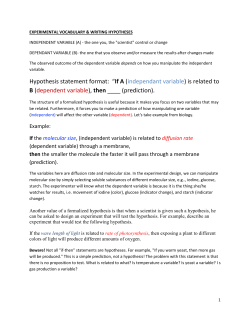
Polymer International Polym Int 55:583–600 (2006) Review How to model the behaviour of organic photovoltaic cells Andre´ Moliton1∗ and Jean-Michel Nunzi2 1 UMOP, CNRS – FRE 2701, Faculte´ des Sciences et Techniques, 87060 Limoges cedex, France Cellules Solaires Photovolta¨ıques Plastiques, Laboratoire POMA, UMR-CNRS 6136, Universite´ d’Angers, 2 Bd Lavoisier, 49045 Angers, France 2 ERT Abstract: In this paper we discuss the optimization of various parameters which govern the behaviour of polymer based and organic photovoltaic cells. General mechanisms leading to the generation of charge carriers and the related loss factors are detailed. Theoretical electrical parameters for bilayer and interpenetrating networks of donors and acceptors (open circuit voltages) are established along with current versus voltage characteristics. An equivalent circuit to a solar cell, considering the effects of shunt resistance across the whole layer, is elaborated. After modelling optical interference and its effects on the photocurrent spectrum, orders of magnitude of the required parameters are established for an efficient solar cell. Deviations from optimal values and their effects on the current–voltage characteristics are discussed. Ageing and degradation effects, and calculations demonstrating the necessary photophysical requirements to achieve long-term stable devices are presented. 2006 Society of Chemical Industry Keywords: organic photovoltaic cell; charge photogeneration; ageing and degradation effects; interpenetrating network INTRODUCTION In general terms, photoelectronic processes refer to the absorption or emission of light by a material. Solids can be subject to various effects, such as photoconduction (conduction once the material is illuminated) or the photovoltaic (PV) effect (generation of a tension under illumination), which are directly tied to transport mechanisms. This article is concerned with the second process. Until very recently, the development of solar photovoltaic systems has been essentially related to inorganic semiconductors, in particular polycrystalline silicon. While the maximum yields approach 25%, the high cost of fabrication of the raw materials yields only limited commercial developments. Alternatives using micro-crystalline or amorphous silicon have been widely studied; and maximum yields are close to 15%. Nevertheless, costs remain problematic due to the use of highly polluting materials, leaving inorganic solar cells as poor competitors against other more prevalent energy sources. In parallel, the use of organic semiconductors developed during the 1970s and 1980s was envisaged as a possible route.1 There are many foreseeable advantages in commercializing organic and polymer-based PV systems, including ease of fabrication and manipulation, flexibility, low weight and low cost. Furthermore, the huge development of research in the field of organic displays based on organic light emitting diodes (OLEDs) has contributed to the knowledge of the physics and chemistry of organic semiconductors. These materials, such as π -conjugated ones, are almost the same as those used in organic photovoltaics.2,3 In an OLED, the physical steps go from the macroscopic scale (current injection) to the microscopic scale (radiative emission from one molecule or macromolecule). The mechanisms involved in an organic photovoltaic cell are reversed, going from the microscopic scale (radiative excitation of one molecule) to the macroscopic scale (generation of electrical power). However, this does not mean that the physical mechanisms are simply in reverse order. The laws which govern light emission from an OLED are different from those governing light absorption: in the first case there is a decreasing optical index, while in the second, the light propagates towards an increasing index. Therefore, the well-established Bradley model for OLEDs2 must be replaced by a new scheme, which will be detailed in this paper after having described the various steps for charge carrier generation in organics. In a second step, we will discuss the mechanisms leading to the various loss factors that appear throughout, and which are often associated with different physical scales. Finally, an important discussion is presented concerning the ageing of photovoltaic cell, ageing which will obviously condition the practical applications of PV cells. ∗ Correspondence to: Andre´ Moliton, UMOP, CNRS – FRE 2701, Faculte´ des Sciences et Techniques, 87060 Limoges cedex, France E-mail: [email protected] (Received 6 July 2005; revised version received 26 September 2005; accepted 6 January 2006) Published online 29 March 2006; DOI: 10.1002/pi.2038 2006 Society of Chemical Industry. Polym Int 0959–8103/2006/$30.00 A Moliton, J-M Nunzi GENERAL MECHANISMS IN ORGANIC PHOTOVOLTAIC CELLS Mechanisms leading to the generation and collection of charge carriers in organics The actual PV process is initiated by the absorption of a photon which generates an exciton, that is an excited state. This quasi-particle diffuses within the material as long as recombination processes (of the electron–hole pair which makes up the exciton) do not take place. If the diffusion length is sufficiently long to allow the exciton to meet an internal field, hole and electron separation occurs and the charges are collected at their respective electrodes. In metal–insulator–metal (MIM) structures, only a slight difference in internal potential (Wint ) controls – for a low dissociation yield ηD ≈ 10% – the dissociation of the photo-generated exciton as represented in Fig. 1. Note that Wint = Wanode − Wcathode , i.e. Wint is the difference in work functions of the anode and cathode metals. Instead of crossing the insulating (polymer) layer, electrons are either trapped or undergo recombination with holes, giving rise to a rather unremarkable result.3 Thus it is only heterostructures, with donor molecules (p-type) and acceptor molecules (n-type) which lead to usable results. The production and harvesting of photoinduced charges follow the processes given below. The donor and acceptor materials form an interface which induces charge separation. Figure 2 details the various processes which influence the efficiency (η): (1) Photon absorption (ηA ) – the incident light generates electron–hole pairs at the p-type donor material (PoD ) due to electron transitions from π -HOMO to π ∗ -LUMO bands; ηA depends on the value of the optical absorption coefficient and on the thickness of the donor material. (2) Generation of excitons – the generation of an electron–hole pair, by photoexcitation, results in an excited but neutral state with a limited, finite lifetime; this state is termed an exciton and consists of an electron and a hole paired by an energy (Eex ) that is smaller than the energy gap between the limits of the permitted bands (LUMO and HOMO bands, respectively). If EG is the energy gap, then (EG − Eex ) is the exciton binding energy (around 0.1–0.2 eV in organics). The occupation of these excited states, the LUMO by the electron, and the HOMO by the hole, is termed a nonrecombined exciton, generally observed in organic materials; (3) Exciton diffusion (ηdiff ) – this quasi-particle diffuses inside the donor material as long as recombination processes (of the hole–electron pair which makes ¨ up the exciton) do not take place. Forster (long ∆Wint = Wanode − Wcathode Wanode Insulator/Semiconductor Wcathode hν − Eint + Metal anode Metal cathode Photo-generated exciton Figure 1. Photogeneration of charges in a MIM structure. (6) ηCC (3) ηdiff (5) ηtr HOMO (4) ηTC (5) ηtr IPd - χEa (6) ηCC EF Cathode Acceptor EF Anode Donor (1) ηA LUMO (3) ηdiff E ex Photons hν Frenkel exciton (2) Figure 2. Mechanisms of photocarrier generation in organics. 584 Polym Int 55:583–600 (2006) DOI: 10.1002/pi Organic photovoltaic cells range) or Dexter (between adjacent molecules) transfers can take place between an excited molecule (considered as excitation donor) and a molecule that receives the excitation (excitation acceptor); ηdiff < 1 because various recombination processes can occur in the thick donor material. (4) Hole–electron separation (exciton dissociation) (ηTC ) – if the diffusion length is sufficiently long that the exciton meets an internal field, hole and electron separation occurs. The internal field may be obtained at a donor – acceptor interface, provided the LUMO level of the acceptor is lower than the excitonic state located at the bottom of the conduction band of the donor. More precisely, Peumans4 indicated (see Fig. 2) that the condition which must be fulfilled is Eex > Ipd − χEa , where Eex is the exciton energy (energy of the electron – hole pair in the excitonic state), IPd is the ionization energy of the acceptor, and χEa is the electronic affinity of the acceptor. ([Ipd − χEa ] is the energy of electron and hole just after the charge transfer at the donor–acceptor interface.) As this condition is generally verified, ηTC ≈ 1. (5) Carrier transport towards the electrodes (ηtr ) – this transport involves the classic mechanism for hopping processes in organic materials. Traps can reduce the mobility. If carriers are not infinitely trapped (as for example in lattice defects such as dislocations), we can consider that ηtr = 1. (6) Charge collection at the respective electrodes (ηCC ) – for this to occur most efficiently, the following conditions (opposite to the injection conditions for OLEDs) must be met: (EF )cathode < (ELUMO )acceptor and (EF )anode > (EHOMO )donor . When fulfilled, ηCC ≈ 1. General scheme After the above description of the main mechanisms involved in charge generation, a general scheme can be proposed to describe the successive steps involved in an organic photovoltaic cell, as shown in Fig. 3. In this figure, the sample is represented as a function of the thickness on the left and as a function of Losses at air-organic interface Losses generated by unabsorbed photons Energiy EG Energy gap : Sample hν : incident photons (1) Sample Losses generated by unabsorbed photons Propagation Thickness : L Loss factors 1 Thermalisation of the photon energy excess Nanostructure scale ηdiff : recombinations during diffusion Exciton generation (2) and bulk diffusion (3) (4): Separation at D/A interface ηtrD : hole trapping in D ηCC : efficiency due to charge collection at the anode Loss factors Optical processes (5) Hole transport in D (6) Hole collection at the anode Im ηTC : efficiency due to carrier separation (5) electron transport in A ηCC : efficiency due to charge collection at the cathode (6) Electron collection at the cathode RC ηtrA : electron trapping in A Im Condition the I(V) characteristics Figure 3. General scheme for organic photovoltaic effect. Polym Int 55:583–600 (2006) DOI: 10.1002/pi 585 A Moliton, J-M Nunzi the energy on the right. In addition, the various processes described in Fig. 2 are reported with the same numerical identification. Furthermore, for each step, the origin of each loss – prior to the in-depth discussion in the next paragraph – is briefly indicated. than the first (air passing the incident radiation), there is no critical angle and hence weak Fresnel losses appear. As the refractive index of organic materials (norganic ) is ca 1.5, the reflection coefficient (R) is relatively low at ∼4%. (2) Losses due to the diffusion of the incident radiation if the material is crystalline – as organics are generally amorphous, this effect can often be neglected. (3) Losses due to unabsorbed photons5 – two phenomena are active (Fig. 4): • Losses due to the mismatch between the solar spectrum and the band structure of the organic materials. Excess energy, that is to say the energy difference between the incident photon energy (EA ) and the energy gap (EG ) given by E = EA − EG , is lost due to thermalization of hot carriers [towards the bottom of the conduction band, associated with zone A in Fig. 4(a)]. Alternatively, photons with energies too low (Ephoton < EG ) cannot be absorbed and correspond to zone B in Fig. 4(a). Hence the band gap EG must be well adjusted.6 For example, the use of materials with EG = 1.2 eV instead of EG = 2.1 eV allows a photon harvesting of 80% instead of 30%, respectively (as detailed in Fig. 5). • Losses due to an inappropriate sample thickness. If the sample is too thin, then part of the LOSS FACTORS IN RELATION WITH THE VARIOUS PV STEPS As observed in Fig. 3, three main steps appear during photovoltaic conversion. They are: the optical processes; processes at a nanostructural scale; and processes which directly influence the I(V ) characteristics. Prior to discussing the causes of the corresponding losses, it is important to note that in plastic electronics and optoelectronics (components fabricated from films or layers), the technology (taken as a whole) operates at the macroscopic scale (because single molecules are not manipulated as in molecular electronics); however the molecular scale, the nano- and microscopic scales must be also studied because the physical processes operate at all these three levels. Optical losses Various loss mechanisms take place: Absorbed Irradiance (Wcm−2 µm−1) (1) Losses at the air–organic interface – as the second medium (the organic material) is more refractive 0.2 A vanished as heat 0.1 EG)Si= 1.1 eV (a) Usable energy B 0.5 EA 1 EG 2.48 1.2 unabsorbed energy EB 1.5 0.83 2 0.62 λ(µm) E(eV) Energy (eV) Zone A: losses due to the photon energy in excess with respect to the energy gap: ∆E = EA - EG ; that leads to 33 % losses in Si (EG = 1.1 eV) Zone B: photons with energy EB < EG are not absorbed: that leads to 23.5%losses in Si ∆E = EA - EG BC EA (b) EG EB BV Figure 4. Solar spectrum and optical losses due to mismatch with organics band structure. 586 Polym Int 55:583–600 (2006) DOI: 10.1002/pi Organic photovoltaic cells spectral photon flux nphm–2s–1m–1 5.1021 100 4.1021 40 AM 1.5 85% 80 C60 3.1021 60 30 2.1021 30% 20 1021 ZnPc 10 E (eV) 400 2.1 eV 600 40 20 800 1.2 eV 1000 1200 Integrated spectral photon flux (%) Absorption (%) 6.1021 1400 λ (nm) Figure 5. Comparison of solar spectrum, absorption profile of some organic materials (C60 and ZnPc), and profile related to absorbed photon total flux at a given wavelength λ (assuming that all photons with an energy E > EG are absorbed). incident radiation will pass through the sample unabsorbed and as a consequence, without a contribution to charge generation. However, if the sample is too thick, an unreasonable series resistance appears and the exciton generation zone is too far from an interface where exciton dissociation occurs. It is possible then to state that two compromises should be made. First, the thickness of the organic sample must be sufficiently thick to absorb the radiation and sufficiently thin to allow charge generation in the vicinity of an interface (where exciton dissociation occurs) and to present a satisfactory series resistance. Second, the bandgap must be sufficiently small to absorb a maximum number of incident photons, and sufficiently large to limit sample ageing induced by thermalization of hot electrons (which diminish with large band gaps). These conditions may be optimized by the following two optimizations. First, using materials which exhibit a high absorption coefficient (α), which is the case for organics and organic polymers (where α ≈ 2 × 105 cm−1 ). This means that the absorption is high even when the films are relatively thin, for example when the thickness (L) = 100 nm, I(L) ≈ I0 /10 and only 10% of incident light is unabsorbed. Second, by preparing stacks of various materials in an order of decreasing band gap, so that each material converts the part of the solar spectrum associated to its own band gap. Given that α = 4π/λ, where η is the absorption index, α increases as λ decreases. Thus blue radiation is absorbed near the surface in the large band gap materials while the red radiation is absorbed at greater depths in the film in the narrow band gap material. Furthermore, as described below, interference effects can be produced inside a photovoltaic cell Polym Int 55:583–600 (2006) DOI: 10.1002/pi to generate a maximum electric field (associated with the incident light wave) in the regions where exciton dissociation can occur. Mechanisms at the nanostructural scale Transfer of excitation between an excited molecule and a neighbouring molecule of the same type in an amorphous structure This mechanism is associated with the exciton diffusion which occurs successively between an excited molecule (playing the role of donor) and a neighbouring molecule (playing the role of acceptor). When adjacent molecules are the same, any internal electric field taking place precipitates the following two phenomena: • Direct exchange interactions between molecules adjacent to donors and acceptors (for example, hopping or excitation diffusion between overlapping electron clouds of adjacent D∗ and A molecules), which gives rise to a short range Dexter transfer (of the order of 0.3–2 nm). The Dexter mechanism, ¨ in contrast to the Forster mechanism, does not rest upon allowed transition probabilities in donor and acceptor molecules. Only the total spin of the system must be conserved [D∗ A then DA∗ , as identified in Fig. 6(a)] during the transfer of excitation via overlapping electron clouds, and an exciton transferred in this way retains its spin configuration. It is a transfer over short distances which decays exponentially with distance. • Electrostatic interactions (Coulombic interactions due to preponderant dipole–dipole interactions) ¨ which give rise to long-range Forster-type transfers (of the order of 3–10 nm). Spins of both A acceptor and D donor molecules are conserved during ¨ Forster transfers under a condition imposed by 587 A Moliton, J-M Nunzi allowed dipolar transitions in the donor and acceptor molecules [see the example given in Fig. 6(b)]. However, if the sample thickness is reduced, in order to verify this last condition, the absorption and thus the photovoltaic effect risk being significantly reduced. The above transfer processes can be limited by phenomena such as bimolecular recombination, which reduces the exciton diffusion yield. Furthermore, when molecules are distributed in aggregates, specific levels associated with the Gauss positions then appear, with new allowed and forbidden transitions. As a result, and as a function of the aggregate type, exciton diffusion is then reinforced or blocked as discussed below. Finally, in a general manner, we can consider that the diffusion yield (characterized by ηdiff ) is high and around 100% if each layer has a thickness of around (or less than) the diffusion length of the exciton. 1 D* Transfer of excitation between an excited molecule and a neighbouring molecule of the same type, and in aggregate structures3,7 Two types of structures may be studied, one associated with J aggregates where molecular dipoles are mainly in a single line (top to bottom), and the other based on H aggregates where molecular dipoles are mainly parallel. For J aggregates, shown in Fig. 7(a), the transition moments of the dimer can be summed (momentum M+ ) to give an allowed transition (indicated by the full 1 (b) A 1 1 1 D* (a) D (c) 1 A* A ¨ Figure 6. Excitation transfer, between singlet states, from D∗ to A following: (a) Dexter mechanism; and (b) Forster mechanism. (c) State following excitation transfer according to 1 D∗ + 1 A → 1 D + 1 A∗ . M− Exciton Allowed transition (fluorescence) Short diffusion (≈ 10 nm) of excitation Strong absorption Forbidden transition Fluorescence (a) Absorption J aggregates M+ Two monomers One dimer H aggregates Long diffusion (≈ 100 nm) of excitation M− Forbidden transition (weak fluorescence) relaxation Exciton Strong absorption Forbidden transition Fluorescence (b) Absorption M+ Two monomers One dimer Figure 7. Transition and excitation diffusion for (a) J aggregate; and (b) H aggregate. 588 Polym Int 55:583–600 (2006) DOI: 10.1002/pi Organic photovoltaic cells arrow) towards the lower level with exciton formation, or alternatively can zero each other out (momentum M− corresponding to energy E− ) resulting in a forbidden transition (indicated by the dashed arrow) towards the upper level. A similar result is obtained with parallel monomer orientation (H aggregates) shown in Fig. 7(b), except that now the allowed transition arises from the upper level while the forbidden transition is from the lower level. The consequence of these effects on the optoelectronic properties are: • For J aggregates [Fig. 7(a)], as the transition towards the fundamental level is allowed, excitons can easily recombine, and luminescence is favoured. However, the excitons only diffuse over short distances, leaving little chance that they will meet a centre, such as a donor/acceptor interface (in bilayer or volume heterojunction), which would permit their separation. Hence, the photovoltaic effect is penalized. • For H aggregates [Fig. 7(b)], following relaxation from the higher to the lower excited level, any fluorescence in the system will be very weak and will penalize any luminescence. Once the system is relaxed, the return from excited to fundamental states is less probable and the excitation (exciton) can diffuse over relatively long distances (∼100 nm). A donor–acceptor interface can then be reached, displaying a property benefiting the photovoltaic effect. Transfer of excitation between a donor molecule and an acceptor molecule of differing type located at an interface In single layer organic (polymer) photovoltaic cells, the internal field (built-in electric field) at the junction is evaluated at around 106 V cm−1 , and the exciton dissociation yield is low at around ηD < 10%, as indicated above. In order to reinforce the dissociation mechanism, a more efficient structure, built up of a donor–acceptor (DA) heterojunction, is used with organic- and polymer-based materials. As shown in the band scheme in Fig. 8, the donor material has a low ionizing potential (IPD ) from the highest occupied molecular orbital (HOMO), and the acceptor material has a high electronic affinity (χA ) from the lowest unoccupied molecular orbital (LUMO) level. If Eex denotes the exciton energy in the donor material (energy of the electron–hole separation), the exciton (a) (b) Eex D A IPD - χA Eex IPD - χA D A Figure 8. Condition for charge transfer: (a) allowed; and (b) forbidden. Polym Int 55:583–600 (2006) DOI: 10.1002/pi binding energy in D materials is EGD − Eex (typically around 0.1–0.2 eV). After the dissociation of the strongly bound exciton with a free electron polaron in the acceptor material and the free hole polaron in the donor, the corresponding state has an energy given by IPD − χA . If Eex > IPD − χA the chargetransfer reactions D∗ + A → D+ + A− and D + A∗ → D+ + A− will take place [Fig. 8(a)]. Conversely, if Eex < IPD − χA , such charge-transfer reactions are energetically unfavourable [Fig. 8(b)]. As dissociation occurs within a few hundred femtoseconds, it is a process which is much faster than any other competing process, and the charge transfer efficiency ηCT ≈ 100%. Losses due to electrical mechanisms When holes and electrons are generated in donor and acceptor materials, they have to be transported through the bulk of the organic materials towards the electrodes (anode and cathode, respectively). During these bulk processes, trapping of carriers can occur. However, if carriers are trapped for a finite time (in shallow traps for example), the mobility is affected. Carriers can finally be collected at electrodes without losses and ηtr ≈ 100%. Conversely, if the carriers are trapped for an infinite time (by reacting with impurities such as oxygen in the bulk for example), they are lost with respect to electrical current or bias voltage. The resulting loss effects depend on the nature of the trap, and the mechanism can appear as a transient regime due, for example, to saturation of deep traps (with negligible emission rates) or as a nontransient regime due, for example, to traps generated by oxygen diffusion from the outer environment where stationary trap generation also takes place. Furthermore, at organic–inorganic interfaces such as at the electrodes, a variety of different trappings can also occur, possibly associated with Fermi level pinning. A charge collection efficiency ηCC ≈ 100% can be obtained when the interface defect density is negligible. A soft deposition process, which leaves a negligible number of dangling bonds in organic material and/or dense electrode materials which do not permit diffusion of impurities from outside the cell, may be used to attain this. ELECTRICAL CHARACTERISTICS IN ORGANIC PHOTOVOLTAIC CELLS The I(V ) characteristics without exposure to light are the result of the superposition of bulk transport mechanisms with electrical properties of the organic–electrode interface. Generally, electrical characteristics are essentially interface-dependant under the low voltage/low current regimes, while they are bulk-dependant in high voltage/high current regimes (Fig. 9). In the latter case, the current density varies as V 2 d −3 in accordance with the Mott–Gurney law, which is associated with the space charge limited current (SCL) law. More accurately, this law is 589 A Moliton, J-M Nunzi J (A m−2) 103 102 10 J∝ V²/d3 1 Space charge limited current J∝ exp(qV/kT) 1 Diffusion current 10−1 10−2 J ∝ V/d (local leakage Currents) 10−3 −1 −0.5 0 0.5 1 1.5 2 V Figure 9. I(V) characteristics with the different domains. modified to take into account the real mobility associated with the trap distribution (and leading to laws expressed as a function of V m+1 d −(2m+1) , where m is a parameter which characterizes trap distribution). Under solar irradiation, as is the case for inorganic PV cells, there are three relevant points to be detailed, namely Ishort−circuit (ISC ), Vflat−band (VFB ) and Vopen−circuit (VOC ). Organic PV cell with donor–acceptor bilayer8 – 10 Short circuit conditions Under short circuit conditions, and at the interface between D donor and A acceptor, two currents occur. One is the drift current which is a reverse current induced by the internal electric field (Eint ) (produced by the potential slope that appears following Fermi level alignment). The other is a current associated with the carrier diffusion from the interface (where carrier pairs generated by the irradiation separate). As a result we also obtain an ISC reverse current [Fig. 10(a)]. Flat band (FB) regime This regime is obtained after anode polarization (with respect to the cathode) with a positive bias voltage given by WITO − WAl , VFB = = q where WITO and WAl are the work functions of anode and cathode electrodes which induces a flat band in the band scheme. Indium tin oxide (ITO) is a commonly used transparent anode. Then, as shown in Fig. 10(b), the internal built-in electric field vanishes along with the drift current, to leave a diffusion current generated from the D–A interface by dissociation of excitons induced by solar irradiation. VOC potential (open circuit, associated with a zero current) Under open circuit conditions, the resulting current density must become zero, so that drift and diffusion 590 current densities compensate each other, as shown in Fig. 10(c). In order to obtain such a result, and with respect to the flat band voltage, a supplementary extra voltage (VPs0 ) must exist at the anode in order to obtain a drift current density that verifies (for example, for electrons) jnPs = qnµn grad(VPs0 ) = jnDiff . The open circuit voltage (with zero current density) can then be given by VOC = VFB + VPs0 , where VFB corresponds to the difference in work function of the electrodes, and VPs0 to the necessary potential that generates a drift current, which itself compensates exactly the diffusion current produced by the accumulation of charge carriers at the donor/acceptor interface during illumination. Organic PV cell based on a bulk-heterojunction interpenetrating network11,12 The formation of bulk heterojunction by mixing a donor material such as poly(3-hexythiophene) with an acceptor such as 6,6-phenyl C61 butyric acid methyl ester (PCBM) leads to an enhancement of the ISC current, owing to an increase in interfacial surface areas for charge separation. These mixed materials are usually obtained via a ‘wet’ solvent-based route in the case of polymers,13,14 or a dry route (co-deposition under vacuum) for small molecules.4 In the bulk-heterojunction structure, two specific cases can be highlighted: • when there is a nonohmic contact, as detailed in Fig. 11(a), a MIM-type behaviour is observed, and hence VOC = VOC1 = electrodes . However, when using a Ca cathode (ohmic contact with s = 2.9 eV) instead of an Au cathode (nonohmic contact with Ws = 5.1 eV) the VOC variation is only around 160 mV. In this case, such a deviation from the MIM potential can be explained by the pinning of the cathode Fermi level to the lowest unoccupied molecular orbital (LUMO) level of the acceptor. Polym Int 55:583–600 (2006) DOI: 10.1002/pi Organic photovoltaic cells (c) Electron diffusion VPs0 EF Al electron drift Irradiation JDiff = Jdrift ⇒ VC0 = VFB + VPs0 Donor Acceptor hole drift EF Hole diffusion ITO Eint = − grad VPs0 I VFB V VOC Current orientation ISC Irradiation Electron diffusion W −W Electron = ITO Al diffusion∆V=∆Φ q Donor Drift EF EFn EFp ITO EF Al VFB=∆Φ Donor EF Al Drift Irradiation (b) (a) Acceptor Hole diffusion Acceptor EF ITO Current Hole diffusion Eappl= − grad VFB Eint Figure 10. Origin of current and voltage values in bilayer devices: (a) at I = ISC : drift and diffusion currents in same orientation. Arrows give flux orientation (opposite to electron current). Reverse current as a result. (b) V = VFB in the flat band regime; Eint = 0 and no drift current, just diffusion current remains (which is a reverse current). (c) V = VOC with VOC = VFB + VPs0 = + VPs0 where VPs0 assumes a drift current (jnPs = qnµn EPs0 for electrons) equal to the diffusion current (jnDiff for electrons). • when there is ohmic contact (for example at a cathode made from Ca or LiF), the negative and positive electrodes, respectively, match the LUMO level of the acceptor and the HOMO level of the donor. A correlation is thus expected, and in fact the maximum VOC is established as in VOC = VOC2 = ELUMOacceptor − EHOMOdonor . This value is governed by the bulk material properties illustrated in Fig. 11(b). If the Fermi levels of the anode and the cathode are pinned15 to EHOMOdonor and ELUMOacceptor then we have VOC2 = ELUMOacceptor − EHOMOdonor ≈ s anode − s cathode . Furthermore, it seems that the band bending at the ohmic contacts reduces this open circuit voltage by around 0.2 V for each contact. CURRENT VERSUS VOLTAGE CHARACTERISTICS AND PHOTOVOLTAIC PARAMETERS Current versus voltage characteristics If a nonirradiated junction is biased with a voltage V , the current of the minority carriers is the saturation Polym Int 55:583–600 (2006) DOI: 10.1002/pi current denoted by Is , while the majority current is exponentially reinforced to become IMaj qV = IS exp kT The resulting current density is thus: qV −1 i = IS exp kT When the junction is irradiated, a reverse current (Iph ) appears and the current density becomes [characteristics shown in Fig. 12(a)] qV − 1 − Iph I = IS exp kT Under irradiation, the plotted curve no longer goes through the origin, and the irradiated biased junction can thus work as: • a rectifier with a forward bias V > VOC in the first quadrant; 591 A Moliton, J-M Nunzi and V = Vm so power (Pmax ) fits the values I = Im that Pmax = Vm Im . • a photodiode with a reverse bias in the third quadrant; the measured current is approximately proportional to the irradiation and when V → 0, we also find that I → ISC ≈ −Iph (the photocurrent approximates to the short-circuit current); and • a photovoltaic cell without external bias, but with a current flowing through a load resistance RL in the fourth quadrant so that the photovoltaic function is not only reduced to the open circuit. In this fourth quadrant, the product of V · I is negative so that power (and electrical energy) can be produced by the device. With I = −I, the curve I (V ) can be depicted for the general case in the first quadrant [as in Fig. 12(b)], where the optimized (maximum) The fill factor (FF) is then defined as the ratio of Pmax to VOC × ISC and can be written FF = Pmax /VOC × ISC . Furthermore, the open-circuit voltage (VOC ) can be directly deduced from the expression giving I. With I = 0 we then have VOC Iph kT Log = +1 q IS From this, it can be observed that for a low value of Is (as found in organic photovoltaic cell) there is a large apparent value of VOC . Vacuum level (a) e- ΦS cathode ΦS anode E = hν VOC2 VOC1 ≈ ∆Φelectrodes Donor Acceptor Vacuum level (b) e- ΦS cathode ΦS anode E = hν VOC2 = EHOMOdonor - ELUMOacceptor ≈ Φs anode - Φs cathode (with Fermi levels of anode and cathode pined to EHOMOdonor and ELUMOaccepor) VOC2 Donor Acceptor Figure 11. Open circuit voltage for bulk heterojunction with: (a) nonohmic contact; and (b) ohmic contact. (a) (b) I I’ |ICC| I’m V -Is VOC Maximum power rectangle V ICC = - Iph Vm VOC Figure 12. (a) I(V) characteristics and (b) I (V) characteristics with the maximum power rectangle. 592 Polym Int 55:583–600 (2006) DOI: 10.1002/pi Organic photovoltaic cells Photovoltaic parameters The internal quantum efficiency (IQE), is defined by IQE = ηdiff × ηTC × ηtr × ηCC , while the external quantum efficiency (EQE), is given by EQE = ηA × IQE. In fact, the EQE obtained by the multiplication of all the efficiencies represents the ratio between the number of generated electrons to the number of incident photons. This coefficient, also named the incident photon-to-current efficiency (IPCE) represents the ratio between the measured photocurrent and the intensity of the incoming monochromatic light. The former is expressed as the number of collected electrons per unit time over a unit area, as in JSC ISC /S = e e where JSC = ISC /S is the current density in A cm−2 for a given surface (S). The latter is expressed as the number of incoming photons of a certain wavelength (λ) per unit time and area, as in Ee φe /S = hc/λ hc/λ where φe is the incident energetic flux (expressed in Watts) and Ee is the illumination defined by Ee = φe /S (in W cm−2 ). Overall, we thus have EQE = JSC hc hc ISC = × × φe eλ Ee eλ With λ expressed in µm, in numerical terms EQE(λ) = 1.24 JSC λ × Ee Finally, the external power conversion efficiency (η) is defined as the ratio of the maximum electric power (Pmax ) to the energetic flux e = Ee × S, which becomes, when expressed more fully η= Pmax FF × ISC × VOC = e e This yield is the maximum value for the theoretical yield. To optimize the yield, each of the three factors in the numerator has to be placed at a maximum. In practice, the yield is diminished by two factors: series and shunt resistances in the cell, and reflection from the light facing the surface of the cell. The I Iph qV i = IS exp −1 kT (a) I’ = Iph − i following section discuses how these parameters can be improved. EQUIVALENT CIRCUIT TO A SOLAR CELL Equivalent circuit to an ideal solar cell Given the above noted equation for current density in a biased and irradiated junction, qV − 1 − Iph I = IS exp kT the cell can be thought of as a current source where Iph is a reverse current proportional to the incident light in parallel with a diode in the dark, which delivers a current qV −1 i = IS exp kT We thus obtain the equivalent circuit for an ideal solar cell, outlined in Fig. 13(a), which consists of a current source and an ideal diode in parallel. If the junction is connected to a load resistance (RL ), the voltage (V ) is the result of the ohmic fall of the current through RL (in an open circuit, RL → ∞ and V → VOC ). The orientation of Iph towards RL results in a V which induces a forward bias across the junction so that the current (i) is a forward current in the direction opposite to Iph . Alternatively, we can consider that the direction of the photocurrent in RL induces a voltage across the junction which generates the forward current i in the direction opposite to Iph , so that in the external circuit we do not observe the entire Iph photocurrent, but only I = Iph − i. Equivalent circuit for a real solar cell When the contact resistances (electrode resistivity and metal-material interfaces) and the ohmic losses (due to the bulk resistivity of the materials) generate a non-negligible resistance in relation to the load resistance, we must include in the equivalent circuit a series resistance (rs ). If Vj denotes the voltage across the junction, the voltage V across the cell is reduced to V = Vj − rs I , and in the first quadrant we have: qVj −1 I = Iph − IS exp kT q[V + rs I ] = Iph − IS exp −1 . kT I Iph i V RL I’ rs ip V rp Vj RL (b) Figure 13. (a) equivalent circuit of (a) ideal cell connected with a load resistance RL , and (b) of real cell with series (rs ) and shunt (rp ) resistances. Polym Int 55:583–600 (2006) DOI: 10.1002/pi 593 A Moliton, J-M Nunzi • For a high bias voltage, rs −1 = [dI/dV ]I=0 . Therefore, as the bias voltage increases, the cell conducts considerably more than the shunt resistance rp , which can now be neglected under this regime. Therefore, the I(V ) characteristics mainly depend on the resistance rs . • for a low bias voltage, rp −1 = [dI/dV ]V =0 and the cell conducts little current. The current now mainly depends on the series of resistances rp + rs ≈ rp , i.e. it is only rp which influences the cell’s characteristics. Furthermore, when leakage currents (which include shunt currents through short-circuits) arise across the cell, we can take into account this component by introducing a parallel resistance (rp ) such that rp → ∞ when the leakage current ip ≈ 0. The equivalent circuit, detailed in Fig. 13(b), describes qVj Vj I = Iph − i − ip = Iph − IS exp −1 − kT rp Replacing Vj by Vj = V + rs I we obtain Finally, the slopes of the characteristic I(V ) under irradiation, calculated for I = 0 (for an open circuit) and in V = 0 (for a short circuit) give the inverse values of the series resistance rs and of the shunt resistance rp , respectively (see Fig. 14). If rs increases, the slope of the characteristic decreases in the first quadrant and Icc also decreases. If rp decreases, the slope increases in the fourth quadrant, and VOC then decreases. qV + rs I V + rs I −1 − I = Iph − IS exp kT rp While in an ideal cell the external circuit does not exhibit the total photocurrent (Iph ) but only I = Iph − i, a real cell gives rise to a more pronounced reduction. This is because the shunt resistor rp introduces the leakage current (ip ) leading to I = Iph − i − ip . Simultaneously, the series resistor takes up the voltage rs I . In ideal cells, we have rs = 0 and rp → ∞. Any departure from these values gives an indication of the imperfections in a diode. Assuming that rs is always small and that rs << rp , we can estimate the values rs and rp . By differentiation of the last equation giving I we find that: EFFECT OF A SHUNT RESISTANCE ACROSS THE WHOLE LAYER If there is a leak current across the whole cell, due to porosities for example, a new resistor (rp2 ) must be introduced as indicated in Fig. 15(a). The effect of this resistance is to reduce the VOC voltage [following I ideal characteristic real characteristic rs-1 ; ideal case : rs-1→∞ and rs= 0 VOC ICC V rp-1 ; ideal case : rp-1 = 0 and rp→∞ Figure 14. Reverse values of series resistance (rs −1 ) and shunt resistance (rp −1 ) linked with the slope characteristics at V = VOC and V = 0 respectively. (a) (b) I with rp2 I Iph I’ rs i Without rp2 ip rp2 rp Vj V V’OC RC ICC VOC V Figure 15. (a) equivalent circuit with additional rp2 shunt resistance due to leakage currents, and (b) effect on the I(V) characteristics. 594 Polym Int 55:583–600 (2006) DOI: 10.1002/pi Organic photovoltaic cells a factor rp2 /(rp2 + rs )] which in turn becomes V OC < VOC , as shown in Fig. 15(b). MODELLING OPTICAL INTERFERENCES AND THEIR EFFECTS ON THE IPCE SPECTRUM Principles A photovoltaic cell is a multilayer structure which receives incident light. Because of successive reflection and transmission at various interfaces (described by an Ijk matrix at the ‘jk’ interface identified in Fig. 16) and during the crossing of m stacked layers (Lj matrix for the ‘j’ layer, where absorption and dephasing occur for the wave), matrix calculation permits a determination of the electrical field. The average absorbed power at the position x can be expressed using4,16 Q(x) = F + (x) · F − (x) · I(x), where F + (x) and F − (x) are the components of the optical electric field propagating in the positive and in the negative directions, respectively, and I(x) is an interference term. This latter term is of importance in thin optical layers as used in polymer-based and organic photovoltaic cells. Effect of thickness of interface layers on the IPCE spectrum As an example we show in Fig. 17 the IPCE spectrum17 of an Al–poly(3,4-ethylenedioxythiophthalocyanine–ITO (Al– phene)–C60 –copper PEDOT–C60 –CuPc–ITO) photovoltaic cell. The j=0 j=1 j=2 E+0 E +1 E +2 E-0 Air E-1 E-2 j k E+j E+k j = m j = m+1 E+m E+m+1 E-j dj E-m Lj E-k E-m+1 Substrate m layers x Ijk Figure 16. Modelling interference effect in multilayer systems. poly(3,4 ethylenedioxythiophene) (PEDOT) acts as a near-transparent hole transport and injection layer, C60 is the acceptor layer, CuPc the organic donor layer and the ITO the transparent anode. The light enters on the anode side. With an 80 nm thick film of PEDOT, only the contribution from the CuPc appears, while with 100 nm of PEDOT there appears two peaks, one attributed to C60 (and centred around 480 nm) and the other (around 650–700 nm) due to CuPc. This behaviour is due to changes in the position of the maximum value of the optical electric field. When the PEDOT is only 80 nm thick, the field is at a maximum in the CuPc layer. When the PEDOT is 100 nm thick, the optical electrical field maximum is in the vicinity of the C60 –CuPc interface, maximizing contributions from both layers to the optical absorption. As detailed above, this technique allows a closer matching of the device to the solar spectrum. ORDERS OF MAGNITUDE OF THE PARAMETERS OF AN EFFICIENT SOLAR CELL The current The present day aim is to discern how parameters might be optimized so as to prepare a photovoltaic cell based on organic materials, which exhibits a solar efficiency in excess of 10%. The main problem remains driving the current through the device. Using the worst case scenario, if the voltage at maximum efficiency (Vmax ) is low, say Vmax = 0.5 V, then 10% solar efficiency can be attained with 10 mW cm−2 electric power, which implies that the current density (Jmax ) should be of the order of Jmax = 20 mA cm−2 . However, if Vmax can be increased to 1 V, then Jmax = 10 mA cm−2 . A more in-depth knowledge of the current flow will permit an optimization of several parameters such as the minimum mobility requirements, the maximum permitted trap density, the maximum permitted series resistance, and the characteristic times which must be taken in account for device operation. 0.018 0.016 Arbitrary Units 0.014 80 nm PEDOT 100 nm PEDOT 0.012 0.01 0.008 0.006 0.004 0.002 0 300 400 500 600 700 800 wave length (nm) Figure 17. IPCE spectrum for various thickness of a PEDOT layer in photovoltaic cells (Al–PEDOT–C60 –CuPc–ITO photovoltaic cell). Polym Int 55:583–600 (2006) DOI: 10.1002/pi 595 A Moliton, J-M Nunzi Initially, we will assume that charge transport is neither limited by traps nor by the metal–semiconductor contacts at the electrodes. In fact, we are looking for an ideal case where the current mobility is limited only by space charge. We shall assume that the material is a dielectric or a semiconductor. Child’s law for solids gives the maximum current density (J) which can flow through an homogeneous dielectric under a bias V . It is also called the space charge limit (SCL) law, and as such gives 9 V2 JSCL = εµ 3 8 d with pentacene.20 One difficulty with this figure is that µmin is the zero-field mobility, as given by the Poole–Frenkel law, as in µ0 exp(−0 /kT ), where 0 is the charge activation energy for hopping [in this case with V = VFB , the electric field is zero and the field dependant term becomes exp(0) = 1 and does not appear in the mobility formula]. The mobility minimum is significantly lowered in the case of dyesensitized solar cells in which most of the material is conducting (for example those based on TiO2 and electrolytes). where ε is the dielectric permittivity of the material, d its thickness and µ the charge mobility. For instance, under short circuit conditions, the internal bias is almost (as shown in Fig. 10), which we can estimate at around 0.5 V. Therefore, the minimum mobility required to drive the current Jsc = 20 mA cm−2 through a device with typical thickness d = 100 nm and relative permittivity εr = 4 is 10−4 cm2 V−1 s−1 .18 This very low mobility limit explains why such large short circuit currents can be driven through devices prepared from low mobility polymers including the soluble derivatives of the widely used poly(para-phenylene vinylene) (PPV).19 These materials are not optimized for PV applications. When the solar cell produces energy, the external voltage Vmax that maximizes energy production is almost equal to the flat band voltage (VFB ), as in Vmax ≈ VFB . This is the voltage which will maximize the fill factor. In such case, charges will no longer be extracted from the device under an internal field by drift but by diffusion. The charge mobility required to extract the PV charge from the device can nevertheless be estimated in the same way as above. The maximum charge (Q) stored in the device with a capacity (C) is given by Q = CVmax . Therefore, the current is I = Q/t where t is the average transit time. Under a diffusion regime, where charges must go to the electrodes, the onedimensional diffusion law given by d 2 = 2Dt yields the average transit time. The diffusion coefficient (D) may be obtained from Einstein’s law, D = µkT /e, where e is the charge and T the temperature. We can thus directly find a modified Child’s law for the diffusion regime, as in Traps The maximum ‘affordable’ trap density NT is relatively easy to calculate given the above considerations. It must be smaller than the stationary charge density (NS ) under solar illumination, the device being charged to its optimum working point. Charge density is thus given by Vmax NS = ε 2 ed JSCLdiff ≈ 2εµkT Vmax ed 3 Under the same conditions as above, at room temperature, with Vmax at 0.5 V, the minimum mobility required to extract a current Jsc = 20 mA cm−2 from an efficient cell is thus µmin = 8 × 10⁻³ cm2 V−1 s−1 . This is not the largest mobility achievable in molecular crystals, but it is the minimum for holes and electrons in their respective donor and acceptor domains. For instance, a field-effect hole mobility of 9 × 10⁻² cm2 V−1 s−1 and an electron mobility of 9.6 × 10⁻³ cm2 V−1 s−1 were recently obtained in an ambipolar mixture of a derivative of a perylene diimide 596 We find that NS ≈ 1016 cm−3 is the upper trap density limit. It must be compared to the density of molecular units, which was found to be N0 ≈ 3 × 1021 cm−3 in pentacene thin films. If the trap density is much smaller than NT ≈ 1015 cm−3 , it will not affect an efficient solar cell and it will not be necessary to account for traps in modelling charge transport in solar cells. Contact resistances In order to prepare an efficient solar cell device, it is unacceptable to have a current limited by metal–organic (Schottky) junctions at the electrodes. This can be overcome by engineering. The presence of Schottky junctions may result in a reduction of the VOC , and may lead to a counter-productive diode which injects a current opposite to the photovoltaic current. Such ‘counter diodes’ can be identified by their production of a characteristic S-shape in their I/V -plots when subjected to illumination. Such an effect generally leads to low fill factors of less than 0.25. The series resistance of the solar cell must be low enough so that the current that is produced is actually dissipated in the external circuit. This current, which corresponds to a density of 20 mA cm−2 , increases with the size of the device. As the current is produced under 0.5 V, this means that the product of the series resistance (rs ) and the active device surface (S) must be considerably lower than 25 cm2 . An effective limit can be estimated as around rs × S = 2.5 cm2 . Similarly, the product of the shunt (parallel) resistance (rp ) by the active device surface should be much greater than 25 cm2 , in order to ensure current dissipation outside the cell. A lower limit can be given as around rp × S = 250 cm2 . It should be noted that the product of a series resistance with the solar cell surface appears with the units cm2 , and should not be confused with the Polym Int 55:583–600 (2006) DOI: 10.1002/pi square resistance of the transparent conducting oxide (TCO) film, which has the units per square (where dimensions of width and length are equal). It means simply, as current increases with size, that the larger the surface of the cell, the smaller the resistance of the transparent conducting oxide. In other terms, if unit solar cells were square shaped and connected through their sides, the square resistance of the TCO represents the maximum surface acceptable for a solar cell unit. For instance, with a 10 per square-TCO, a 2.5 cm2 upper limit of the product of rs × S can be achieved only if the unit cell surface is lower than 0.25 cm2 . Current density (mA cm−2) Organic photovoltaic cells 8.0 7.0 6.0 PCBM - MEH PPV blend 5.0 4.0 3.0 2.0 1.0 0.0 −1.0 −2.0 40 −3.0 −4.0 −5.0 −6.0 −7.0 60 −8.0 −9.0 −10.0 100 −11.0 −12.0 −1.0 −0.8 −0.6 −0.4 −0.2 0.0 0.2 0.4 0.6 0.8 1.0 Voltage (V) INCIDENCE OF DEVIATIONS FROM OPTIMAL VALUES ON I–V CHARACTERISTICS In this section, we describe the incidence of a deviation in the optimum characteristics of a solar cell on its I –V characteristics. As pointed out above, if the current is limited for any reason, this will have a dramatic impact on the I/V plots recorded under illumination. Apart from ‘counter diodes’ (see above), series (rs ) and shunt (rp ) resistances will be affected. While shunt resistance indicates the degree of lost charges due to recombination and trapping, the series resistance reflects the formation of a space charge voltage which appears in opposition to the charge flow. Two main types of effects must be considered. Both affect series and shunt resistances in a different way: • If the current is limited by traps, for instance under low lighting where NT > NS , only carriers of one sign (pseudo-free carriers) contribute to the current. This leads to so-called photoconductivity in which only one type of carrier flows through the device, the other one being trapped. The maximum voltage is unusually small, of the order of Vdiff = kT /e, owing to the diffusion of the free carriers. The number of charges which are lost in the traps is proportional to the current. Therefore, there is a drop in the series resistance, an additional conductivity which is proportional to the illumination, as in rs −1 α Iph . There is also a contribution to the shunt conductivity which accounts for lost charges, and again this is proportional to the illumination, as in rp −1 α Iph . If the trap density is low enough, this behaviour will prevail at low illumination intensities and the cell will recover normal behaviour at higher illumination intensities. • If the current is limited by space charge, this will lead to bimolecular recombination, i.e. charges which cannot escape from the device recombine as electron–hole pairs. Although space charge and bimolecular recombination are different effects,21 they occur simultaneously under large illumination intensity, degrading the fill factor. This is the case in Fig. 18, in which we see degradation of the fill factor with increasing intensity. Solar efficiency drops from 4.8% under 24 mW cm−2 Polym Int 55:583–600 (2006) DOI: 10.1002/pi Figure 18. I/V characteristics monitored in an Ar-glove box under different AM-1.5 illumination intensities: 0, 24, 60 and 100 mW cm−2 . The solar cell was based on a spin-coated poly[2-methoxy-5-(2-ethyl hexyloxy)-1,4-phenylene vinylene]–PCBM interpenetrated network delivering 2.9% nominal solar efficiency.19 to 2.9% under 100 mW cm−2 . Owing to space charge limitation, there appears an additional series resistance rs α Iph 1/2 . There also appears an additional shunt conductivity which accounts for bimolecular recombination, as in rp −1 α Iph 1/2 . The practical example of the solar cell with I/V curves displayed in Fig. 18 was studied in view of the equivalent circuit shown in Fig. 13(b). Results of the fitted rs and rp −1 as a function of Iph are given in Fig. 19. Its dark series resistance was 20 and shunt resistance was too large to be fitted. In conclusion, provided the solar cell is efficient and described in the relevant regime, the I –V characteristics under illumination provide an excellent diagnostic of its most limiting features. EFFECTS OF AGEING AND DEGRADATION In this chapter, we size the necessary photophysical materials requirement for the achievement of stable devices under long-term ageing and illumination. We expect the development of a technology which will reduce significantly the price of solar electricity. A cost reduction by a factor close to 10 should be necessary to produce solar electricity at a reasonable price. This means that the solar modules should ideally be kept for 20 years in outdoor working conditions. We can expect an average 1000 h year−1 nominal sunlight exposition conditions in European countries. Integrated nominal exposition will be 20 000 h. That represents about 10 MW h m−2 absorbed light (if only 50% is absorbed by the cells), about 2 MW h m−2 of electrical energy produced and 8 MW h m−2 ideally dissipated into heat. Outdoor storage time has to be 175 000 h (20 years) at temperatures between −20 and +60 ◦ C or more, on a roof. Several degradation mechanisms have been identified so far. Here are the major ones: 597 A Moliton, J-M Nunzi 2000 • (rs − rs0)2 1500 1000 500 0 0 60 100 20 40 80 Illumination intensity (mW cm−2) (b) 2.0x10⁻⁶ 1.8x10⁻⁶ 1.6x10⁻⁶ 1.4x10⁻⁶ 1.2x10⁻⁶ 1.0x10⁻⁶ 8.0x10⁻⁷ 6.0x10⁻⁷ 4.0x10⁻⁷ 2.0x10⁻⁷ 0.0 • 1/rp2 Shunt resistivity square (Ω−2) series resistance square (Ω2) (a) 20 30 40 50 60 70 80 90 100 110 Illumination intensity (mW cm−2) Figure 19. Evolution of the series rs (a) and shunt rp −1 (b) resistances under illumination. They were fitted from the I/V curves shown in Fig. 18, for the polymer cell of Alem et al.19 • photochemistry, which can occur to an isolated molecule in a vacuum under light, results in the formation of photoisomers or photoproducts; • temperature, which can induce demixion, fusion, recrystallization and even chemical reactions; • water, which is an ionic conductor and will favour electrochemistry at the interfaces; • oxygen, which has three major effects – oxidation, photo-oxidation and chemistry, trapping of electrons; • interfaces at which diffusion can occur, from metal or semimetal electrodes to the polymer films for instance; • impurities, which can diffuse and modify the junction behaviour or react chemically, quench excitons or trap free charges. All the above factors can be considered to be related, but each one requires a different treatment. In addition, and as only an example, small molecules and polymers behave in very different ways. Photochemistry of an isolated molecule M absorbing a photon hν will schematically proceed according to the following mechanisms: M + hν −−−→ M ∗ + kT −−−→ M + + e− This is the favourable case of a photo-donor in a solar cell, and heat is produced. M ∗ −−−→ M + kT This is the unfavourable case leading to nonradiative relaxation, exciton quenching for instance, which heats the material. M ∗ −−−→ M cis This is the unfavourable case of molecules which will have a tendency to isomerize, such as PPV oligomers and polymers free to rotate around C=C bound. The first solution to photochemical degradation is in molecular engineering. For example, the design of conjugated molecules that do not give rise to photoisomers (heterocycles or ladders for instance). The 598 second solution is in the appropriate choice of the donor–acceptor partners and device topology. This can be achieved for example by choosing bi-layer or interpenetrated blend cells, in order to favour low exciton quenching and large exciton dissociation. This can be monitored using the internal quantum efficiency of photogeneration which should be as close as one as possible. Thermal degradation will obviously depend on the materials. The problem is with melting which occurs at higher temperatures and which will change the structure from an optimized one to an inefficient one. For instance, small molecules may recrystallize, amorphous films may dewet, polymer blends may demix, liquid crystals may reorient or become isotropic and oriented dipoles may randomize. The solution may be found in high-transition-temperature materials obtained by crosslinking, reactive PVD or any other solid phase reaction. When containing mobile ions, as is common, water is an electrolyte. Electrochemical reactions, oxidation or reduction will take place under bias. Water is also a bad solvent for most organic materials, so that swelling under moisture will also favour demixion and segregation in blends and mixtures. Water should be removed from the compounds during preparation in a water-free atmosphere. The devices should be encapsulated against water: plastic films and coatings offer good protection against moisture. Owing to its abundance, oxygen is the most dangerous contaminant of organic solar cells. It oxidizes the materials, thus doping the conducting polymers, which is not necessary a drawback. The largest drawback is with photoinduced oxidation, according to the following mechanism involving singlet, triplet and radical states denoted by the superscripts 0, 1 and • , respectively: M 0 + hν −−−→ M ∗0 (light absorption by a singlet molecule) M ∗0 −−−→ M ∗1 + kT (intersystem crossing to the triplet) Polym Int 55:583–600 (2006) DOI: 10.1002/pi Organic photovoltaic cells M ∗1 + O2 1 −−−→ M 0 + O2 0 (electron exchange with triplet oxygen producing singlets) • • M + O2 0 −−−→ M + O2 (radical formation and transmission by diffusion) Radicals are highly unstable and reactive species which degrade molecules and polymers in subfragments. Another drawback of oxygen is that it is an efficient electron trapping centre. So, in the presence of oxygen at a concentration close to the photovoltaic charge density, a solar cell becomes photoconductive, its shunt resistance drops and so does the maximum voltage. Small molecules in thin films are more resistant to O2 than polymers; diffusion is indeed reduced owing to a more compact molecular packing, as with pigments which are highly resistant dyeing materials. The solution to oxygen diffusion is in the fabrication under controlled atmosphere followed by encapsulation of the devices. Unless drilled with holes, glass, metals23 and metal-oxides are resistant to O2 diffusion and may be efficient encapsulation materials. Diffusion can occur at the interface between different materials. The most dramatic in terms of solar cell behaviour is the diffusion between electrodes and semiconductors, especially when concerning a Schottky junction. Indeed, for neutral species, diffusion is activated by concentration gradients, according to the law ∂ 2g ∂ 2c ∂g ∂c ∂c = cµ 2 + µ +D 2 ∂t ∂x ∂x ∂x ∂x where c is the concentration of the diffusing species, g its chemical potential in the medium, and µ = τ/m and D = µkT /m. It is well established, for instance, that indium from ITO diffuses into the electronic polymers, degrading performances.22 Diffusion at the interfaces can be shielded by interfacial layers made of densely packed small molecules. Two kinds of impurities should be distinguished: those introduced during fabrication, and those due to ageing. The former should be removed by purification (this is easier in small molecules which can be purified by sublimation). The latter may be formed from a variety of degradations listed above. Impurities can quench excitons when they absorb at lower energy, but they can also trap free charges, electrons or holes depending on their acceptor or donor behaviour. We can gain deeper insight into long term degradation mechanisms by keeping in mind the necessary condition of low trap density. Degradation mechanisms are not dramatic as long as the induced density of traps is lower than a typical NT ≈ 1015 cm−3 limit. We have about 3 × 1021 cm−3 molecular units absorbing about 1030 cm−3 photons in 108 s. To maintain low trap density, the rate of unwanted Polym Int 55:583–600 (2006) DOI: 10.1002/pi photochemical reactions must be lower than 10−15 , with an average excitation rate of 3 s−1 . In a similar reasoning, we can evaluate the enthalpy of reaction which will give less than 3 × 10⁻⁷ impurities by thermal activation. We get H ≈ 0.4 eV or 10 kcal mol−1 , which is less than the enthalpy of hydrogen bonding. The largest difficulty is with encapsulation, for which the time scale for diffusion is 2 × 10⁵ h. CONCLUSION It is obviously difficult to make an efficient plastic solar cell that will survive outdoors for 20 years, but it is not impossible. It simply requires a lot of work, and we have described in this paper almost all of the individual steps of solar energy conversion into electricity in organic materials. Additionally, OLEDs already work efficiently for about 20 000 h.24 Just to make a comparison, silicon solar cells can produce 50% more energy than our 10% target, but owing to the device thickness and to the process temperature, the energy needed to produce silicon solar modules may be close to 1 MW h m−2 , which makes the global energetic productivity of the technology questionable, the ratio (between silicon- and polymer-based solar cells) being only 3. Conversely, plastic solar cell for which the device thickness is reduced by three orders and process temperature by one order of magnitude can see their global energetic efficiency improved by two to three orders of magnitude. They will become the ideal device to produce delocalized electric energy. ACKNOWLEDGEMENT The authors express their gratitude to Roger C. Hiorns for his help in the preparation of this manuscript. REFERENCES 1 Simon J and Andr´e JJ, Molecular Semiconductors. Springer, Berlin (1985). 2 Bradley DDC, Current Opinion in Solid State & Materials Science, 1:789 (1996). 3 Marks RN, Halls JJM, Bradley DDC, Friend RH and Holmes AB, J Phys Condens Matter 6:1379 (1994). 4 Peumans P, Yakimov A and Forrest SR, J Appl Phys 93:3693 (2003). 5 Ricaud A, Photopiles solaires. Presses polytechniques et universitaires romandes, Lausanne (1997). 6 Sariciftci NS, Materials Today 36–40 (September 2004). 7 Moliton A, Opto´electronique mol´eculaire et polym`ere: des concepts aux composants. Springer France and France T´el´ecom R&D, Paris (2003). [English edition, Optolectronics of Molecules and Polymers, translated from the original in French by Hiorns RC. Springer, New York (2005).] 8 Ramsdale CM, Barker JA, Arias AC, Friend RH and Greenham NC, J Appl Phys 92:4266 (2002). 9 Barker JA, Ramsdale CM and Greenham NC, Phys Rev B 67:075205-1-9 (2003). 10 Koehler M, Roman LS, Iangan¨as O and da Luz MGE, J Appl Phys 96:40 (2004). 11 Brabec CJ, Cravino A, Meissner D, Sariciftci NS, Fromherz T, Rispens MT et al., Adv Funct Mater 11:374 (2001). 599 A Moliton, J-M Nunzi 12 Mihailetchi VD, Blom PW, Hummelen JC and Rispens MT, J Appl Phys 94:6849 (2003). 13 Yu G and Heeger AJ, J Appl Phys 78:4510 (1995). 14 Halls JJM, Walsh CA, Greenham NC, Marseglia EA, Friend RH, Moratti SC et al., Nature 376:498 (1995). 15 Ishii H, Sugiyama K and Ito E, Adv Mater 11:605 (1999). 16 Pettersson LAA, Roman LS and Ingan¨as O, J Appl Phys 86:487 (1999). 17 Brousse B, PhD thesis, Limoges University (December 2004). 18 Nunzi J-M, C R Acad Sci Paris 3:523 (2002). 19 Alem S, de Bettignies R, Cariou M and Nunzi J-M, Appl Phys Lett 84:2178 (2004). 600 20 Unni KNN, Pandey AK and Nunzi J-M, Ambipolar organic field-effect transistor fabricated by co-evaporation of pentacene and perylene, Chem Phys Lett (in press). 21 Nunzi J-M, Juˇska G, Jean F and Arlauskas K, Acta Physica Polonica A 107:377 (2005). 22 Sahin ¸ Y, Alem S, de Bettignies R and Nunzi J-M, Thin Solid Films 476:340 (2005). 23 Gautier E, Lorin A, Nunzi JM, Schalchli A, Benattar JJ and Vital D, Appl Phys Lett 69:1071 (1996). 24 Moliton A and Hiorns RC, Polymer International, 53:1397 (2004). Polym Int 55:583–600 (2006) DOI: 10.1002/pi


© Copyright 2026