
How to Reduce Product Launch Delays Through
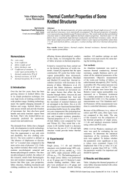
How to Reduce Product Launch Delays Through
Systematic Thermal Design and Validation
DegreeC White Paper:
How to Reduce Product Launch Delays Through Systematic Thermal Design and Validation
Introduction
The need for higher product reliability has driven thermal design to the fore-front in the development of
electronics components and systems. It is well known that the reliable operation of an electronic device
depends largely on its operating temperature – the lower the operating temperature, the longer the longterm reliability of the component. Numerous tests and empirical measurements have confirmed that
component failure rates are exponentially related to temperature due to a number of thermally-dependent
failure mechanisms. Not only that, any excess in temperature beyond the design limit would result in an
instant failure of the component and hence the rest of the system. Thus thermal design has steadily gained
importance as one of the two primary considerations in the design and packaging of electronic components
and systems – the other being the actual product functionality.
Thermal design is an all-encompassing discipline targeted to the management of heat generated by
electronic circuitry. Thus it is involved in the packaging of electronics at the chip or device level, at the
board level, at the chassis or enclosure level, and at the room level. At every level, the rapid and continuing
growth in packaging density have posed enormous challenges to electronics cooling, and increasingly there
is a need for thermal design to take a synergistic or holistic approach that attempts to squeeze increasing
efficiencies at all packaging levels collectively and at every level individually.
There are three paradigms at work that make thermal reliability the primary consideration in system-level
packaging today:
1.
2.
3.
Increasing clock rates and functional integration at the chip level following Moore’s law, leading
to higher power dissipations per component. Figure 1 shows the recent trend in high performance
chip power dissipation and chip heat flux respectively.
Increasing packaging density at the system level, driven by the demand for higher performance,
higher bandwidths, faster communication, and wider range of services offered per box. This in
turn has resulting in ever increasing heat densities across all product platforms. Figure 2 shows the
historical and expected heat density trends of various types of datacomm equipment.
Maximum chip temperature requirements have not changed much even as the power dissipation
has been increasing rapidly. The vast majority of commercial-off-the-shelf (COTS) components
still have long-term operating temperatures in the range of 85-105°C, and maximum operating
temperatures not to exceed 125°C. Most of the Central Processor Units (CPU) that is the core of
the majority of systems cannot exceed 72°C case temperature without throttling. There has been a
lot of research on high temperature electronics for harsh environments such as under-the-hood
automotive applications where ambient temperatures can reach as high as 125°C, but by and large
the vast majority of the components used in electronics packaging are COTS components.
Chip Heat Flux(watts/cm 2)
200
Max - 2002
150
Max - 2000
Min - 2002
100
Min - 2000
50
0
2001
2003
2006
2009
2012
Year
Figure 1: High Performance Chip Heat Flux Trends (source: NEMI Technology Roadmaps)
Page 2 of 12
DegreeC White Paper:
How to Reduce Product Launch Delays Through Systematic Thermal Design and Validation
Figure 2: Power Density Trends at Facility Level (source: ASHRAE TC9)
The Basic Electronics Thermal Management Task
The basic heat transport phenomena related to cooling an electronic device is schematically shown in
Figure 1. The electronic device could be a packaged silicon chip that processes information, a power supply
that transforms and conditions power input to other devices on a board or chassis, an optical transceiver, or
a light emitting diode (LED). As a by-product of performing its function, the input power supplied to the
device is eventually transformed into waste heat that serves to raise the temperature of the device. In order
to prevent the device temperature from exceeding a known limit which will cause it to fail, the generated
heat must be transported away from the device, eventually into the environment as the ultimate heatsink.
Between the device and the environment, there can be any number of intervening hardware and media
intended to cool the device and bring the device temperature as close as possible to the environment
temperature, and even sometimes necessarily below the environment temperature.
T∞
Tmax ≥ Tj > T∞
qc
qk
qr
Q&
qrb
qcb
Device
qkb
Tj
qkb
qcb
qkb
qrb
Tb
Board
Figure 3: Heat generation and dissipation in an electronic device mounted on a board.
& ) is generated at a relatively small portion of the device called the junction. Part
As shown in Fig.3, heat ( Q
of the heat is conducted from the device package into the board (qkb) which is ultimately lost into the
surrounding media by convection (qbc) and radiation (qbr). The remaining portion of the heat is lost through
the surface of the package by any combination of convection (qc), radiation (qr), and conduction (qk)
Page 3 of 12
DegreeC White Paper:
How to Reduce Product Launch Delays Through Systematic Thermal Design and Validation
depending on the prevailing local environment around the device and the cooling hardware. The device
would generally be at an elevated temperature above the ambient temperature (T∞). The device temperature
is highest at the junction (Tj) and gradually falls across the spreading resistance of the package.
The basic thermal management task is to maintain the junction temperature (Tj) below a known limit
commonly referred to as the maximum operating temperature. With this as the primary objective, the
design of the package to withstand the elevated temperature and distribute the generated heat, the metrics
and characterization of the generated heat, the selection and design of the intervening media and hardware
to transport the heat, and the impact of the environment temperature and heat transport on the short- and
long-term reliability of the device, constitute the core scope of electronics thermal management.
The Need for a Systematic Approach to Thermal Management
In an electronics system that contains hundreds or thousands of electronics, each device would have its own
operating temperature limit. In such situations, the task of maintaining every device below its own
temperature limit could become quite daunting, and requires a great deal of sophistication and experience
in finding a solution. Fortunately, rapid advances have been made in the tools and methods of thermal
management. Sophisticated computational tools are now readily available to simulate and model the
enormous complexity of heat transport phenomena in electronics systems for the purpose of realizing an
optimal design, and advances in testing hardware and methodologies, as well as definition of standards,
have made it possible to troubleshoot and verify the field performance of systems before they leave the
door.
Beyond product reliability concerns, there are other equally important factors that are primary
considerations in the packaging of electronics. Aggressive competition has lead to equally aggressive cost
squeeze across all product segments and services. Thus even though the cooling hardware is traditionally a
small percentage of the cost of a product, the thermal designer is nevertheless under the same price pressure
as others to add to the bottomline. This often limits the number of viable choices for the cooling hardware
and demands that a careful and systematic approach be taken to design and optimize cost-effective
solutions.
An equally important consideration in thermal design is the short design cycle. Shrinking product lifecycles (especially in the commercial sector) make time-to-market one of the primary factors in datacomm
equipment design. Datacomm equipment refreshes occur roughly every 1.5 years. Thus engineers in the
datacomm arena do not have the luxury of long design cycles traditionally obtained in other market
segments. In the datacomm arena the time available from concept to market introduction is very short,
requiring that the thermal design be done right the first time – there is virtually no room for re-design to
make corrections. Due to the short design cycle, thermal design must be carried out concurrently with the
rest of the product development effort, as shown conceptually in Fig. 4.
Page 4 of 12
DegreeC White Paper:
How to Reduce Product Launch Delays Through Systematic Thermal Design and Validation
Po
r
we
Concurrent
Engineering
Fun
Ele ctiona
c
Lay trical l Desi
gn
out ,
,
Sof
twa
re
Procurement
l
ica
ys ign
h
P es
D
Th
e
De rmal
sig
n
Figure 4: Concurrent product development of a datacomm equipment.
Due to reliability concerns, thermal design is normally the lead-in to the physical design activity once the
initial product idea has been actualized into a workable concept. This initial prototyping thermal design is
required to define or validate the overall physical architecture of the product. As the product design
develops, more in-depth thermal analyses are carried out at various points in the design cycle to size or
select cooling hardware, determine the exact physical architecture of the board and components placement,
probe and qualify the thermal health of the equipment under postulated operating scenarios, etc, all to
ensure that the product will function reliably when deployed in the field. The various stages of thermal
design employed through the design cycle is illustrated in Fig. 5.
Page 5 of 12
DegreeC White Paper:
How to Reduce Product Launch Delays Through Systematic Thermal Design and Validation
Functional Design (Power, Hardware and Software)
Expected flow
rates and
temperature rise
Component
details and
board layout
Prototyping
Thermal Analysis
Concept
• Overall cooling
requirements
• Initial cooling
system
specification
Overall chassis
size, plenums,
vents
Modified
board
layout
Detailed Thermal
Design
•
•
•
•
Component temperatures
Detailed cooling profiles
Heatsink design/selection
Probe design envelope:
failure scenarios,
elevated temperatures,
elevation
CAD Files
Initial DVT
• Build and test
mock-up
• Validate
Thermal Model
Final Thermal DVT
• Temperature & Flow
measurements
• Survivability under
failure scenarios
• Thermal controller speed
tuning
• Burn-in
• Agency pre-qual tests
Vent %open
ares, Filter
selection, EMI
mitigation
Mechanical Design
Figure 5: Various stages of thermal design employed for product development
Thermal Design Stage 1: Initial Calculations for Sizing and
Physical Layout
An initial thermal design is used right at the concept stage to qualify the initial thinking about the overall
architecture of the product. The platform, cooling method (conduction, radiation, natural or forced
convection air cooling, liquid or two-phase cooling) and service conditions are normally determined by the
target market and application. The initial thermal analysis is used to check for the feasibility of cooling the
expected total heat dissipation within a given chassis size and available cooling method. The nature and
sophistication of this initial thermal analysis depends on the type of equipment, available information,
experience of the thermal engineer, and availability of time and tools to perform the analysis. The initial
thermal analysis could range from a simple back-of-the-envelope calculation (e.g. the size of a natural
convection cooled box), to a more elaborate such as designing a fan tray to cool a multi-blade server or
router. In all cases the total heat expected to be dissipated in the equipment is uniformly smeared across the
heat dissipating surfaces (normally the board). The main purposes of this exercise is to arrive at a workable
Page 6 of 12
DegreeC White Paper:
How to Reduce Product Launch Delays Through Systematic Thermal Design and Validation
maximum air temperature rise in the chassis. Normally the following items would be determined from the
initial analysis:
•
•
•
•
•
•
Flow configuration: Push, Pull, and Push-Pull
Fan selection and placement, mindful of fan life and acoustic requirements
Required chassis size
Vent sizes, locations, and overall flow resistance
Expected bulk flow rates
Expected air temperature rise
Tota l Flow vs. He ight for the Six-Slot Chassis
900
24.5
24
800
Total Flow
23.5
23
Flo w [cfm]
600
22.5
500
22
T otal C hassis Heig h t [in]
700
Total Flow W ithout
Res trictions in Front and
B ac k Vents
Total Flow W ith Botttom
P lenum Inc reased 1"
Total Chass is Height
400
21.5
300
21
200
20.5
1
1.5
2
2.5
3
3.5
4
4.5
5
Plen u m He ig h t A bo ve Fan T ray [in]
Without Louvers
With Louvers
Figure 6: A prototyping thermal analysis such as shown here employs uniform heat dissipation smeared on all
the boards. This kind of analysis is used to select the appropriate size, quantity, and placement of fans required
to cool the system. In this particular case the analysis also was used to determine the required height of the
chassis as well as the relative benefit of using louvers at the inlet.
Page 7 of 12
DegreeC White Paper:
How to Reduce Product Launch Delays Through Systematic Thermal Design and Validation
Thermal Design Stage 2: Detailed Thermal Modeling to
Optimize and Verify Performance
At the completion of the prototyping thermal analysis, hardware architects would have information on the
cooling available for components they select for the functional design. Mechanical engineers would have
an idea of the overall size of the chassis and spatial requirements for physical layout of chassis. The CAD
file from the mechanical design and the board layout file from the board design, along with physical and
thermal information on the major electronic components, are subsequently used to carry out the next stage
of thermal analysis. This thermal simulation is used to obtain detailed local cooling rates for all important
components in the system. If necessary, iterative simulations, which could involve changes in component
selection and layout, and changes in the mechanical design of the chassis, are made to ensure that all
components are satisfactorily cooled under all postulated operating scenarios. It is therefore of paramount
importance - given the short design cycle - that the thermal simulation platform be compatible with both the
mechanical CAD platform used for mechanical design, and the ECAD platform used for board layout. Both
the mechanical CAD and ECAD files are imported into the thermal design platform to carry out the
detailed analysis.
Figure 7: Example of a detailed
thermal simulation. In this
picture the mechanical CAD
geometry shown on the left is
used directly to generate the
thermal model shown on the
right,
because
both
the
mechanical design and thermal
simulation platforms can share
geometry. As a result any
changes made in the thermal
model can quickly be migrated
into the mechanical design, and
vice versa.
Figure 8: A detailed thermal simulation of the equipment is used to obtain a detailed picture of how
each component is cooled. This kind of analysis can immediately pin-point potential causes for alarm
and ways to mitigate them.
Page 8 of 12
DegreeC White Paper:
How to Reduce Product Launch Delays Through Systematic Thermal Design and Validation
Generally, detailed thermal analysis is used for the following purposes:
•
•
•
•
•
•
•
To help refine the component layout so as to optimize cooling of all components in the system
To help refine the physical layout and mechanical components of the chassis so as to maximize
conduction and surface heat loss from natural convection cooled systems
To help refine the physical layout so as to maximum the air flow rate thru forced convection
cooled systems
To design or select localized thermal management solutions such as heatsinks, heat pipes, thermoelectric coolers, and such. High power components would normally require heatsinks. It is
particularly important to verify the performance of each heatsink in situ in the system model,
regardless of the stated catalog performance. Off-the-shelf heatsinks can be selected and verified
in the detailed thermal model. If an off-the-shelf solution cannot be found, custom heatsinks are
also designed and verified using the detailed thermal model. Some level of grid embedding
capability in the thermal analysis software is particularly useful when designing heatsinks.
To probe the operating envelope in order to ensure that the equipment will perform satisfactorily
under various environmental and service conditions, such as:
o Elevated ambient temperatures
o Redundancy, such as a single fan failure
o Elevation
o Solar radiation
o Filter blockage
The particular set of conditions to satisfy is normally defined by governing standard(s) for the
application and location where the equipment will be deployed.
Acoustic and EMI emissions are other criteria defined in standards which the equipment must
satisfy. The mitigation for acoustic noise is normally to control the fan speeds as a function of the
ambient temperature. The mitigation for EMI emission at the chassis level, is normally to control
the opening percentage of the vents in order to contain the radiated emission within the chassis. In
either case, a detailed thermal model is crucial to ensure that the equipment is cooled adequately at
reduced fan output.
To generate control strategy for thermally controlled systems. Managing acoustic noise normally
requires fan speeds to be controlled in forced air cooled systems. A temperature controller may be
necessary for systems whose temperatures need to be maintained constant during operation. In all
cases the detailed thermal model is useful to generate the control curve that will be implemented in
the controller.
Figure 8: The thermal model shown here on the left was used to generate the airflow rates shown by
the chart on the right. The speed settings shown on the chart were implemented in the thermal
controller and verified through thermal DVT to be adequate for cooling the system
Page 9 of 12
DegreeC White Paper:
How to Reduce Product Launch Delays Through Systematic Thermal Design and Validation
Figure 9: A detailed thermal model may contain
important only components on one or more detailed
boards, as shown on by the example on the left,
while the other slots are represented with
appropriate flow impedance. Normally the detailed
board is inserted into the worst case slot selected
according to the airflow rate. Depending on the
capability of the modeling software it may be
possible to detail every slot in the chassis, as shown
by the example on the right.
Thermal Design Stage 3: Initial DVT to Validate the Thermal
Model
It is beneficial to build and test a physical mockup of the equipment whenever time and cost allow. Despite
the sophistication and capability of modeling tools, some gaffs can still occur in the thermal modeling
especially when an inexperienced user is involved. Even with experienced thermal practitioners some level
of initial DVT can still prove quite invaluable for highly critical systems, or systems that might incorporate
new and unproven cooling technologies. In this case a quick physical mock-up and testing may be used to
verify or discard assumptions made in the modeling.
The initial DVT in essence is used to calibrate and validate
the thermal model. Once the model is validated for a given
set of design parameters and operating condition, then it can
be used for all the other purposes outlined in the detailed
modeling stage. This is normally the best way to go.
Depending on time constraints and cost, a physical mockup
may involve any number of the following:
•
•
•
•
It is far easier and cost effective to
make design changes and test for
various operating conditions in
software rather than prototyping
each change. But testing in
software is only useful if the thermal
model is correct. The initial DVT
helps to ensure that the thermal
model is correct.
A cardboard or sheet metal mockup of the chassis.
Even though this is only a mockup, it is very
important to ensure that the physical layout, venting
pattern, and air filter (as applicable) be as close as
possible to what is envisioned for the final design.
Load boards consisting of heater blocks and other flow obstructions glued or taped onto bare
PCB, cardboard, or aluminum sheets to represent the boards. In many cases the new equipment
may be a derivative of something that already exists. It is better and quicker to use the old boards
in such cases.
A mock up of the fan tray in forced convection cooled systems. The actual fans specified for the
new systems should be used.
Thermocouples and airflow sensors installed at important locations in the mockup
The physical mockup is normally used to test for the following depending on the equipment:
1.
2.
3.
Overall volumetric airflow through the equipment. This is normally done in a wind tunnel
Flow velocities at critical locations throughout the equipment
Where heaters are used, air temperatures at critical locations throughout the equipment
Page 10 of 12
DegreeC White Paper:
How to Reduce Product Launch Delays Through Systematic Thermal Design and Validation
These measurements are used to validate the thermal model. If the model and test results are not in
satisfactory agreement, then the thermal model (or test rig for that matter) needs to be re-visited to bring
them in closer agreement. A validated thermal model is the conclusion of this exercise. The model may
then be used in subsequent numerical testing to refine the design and test for postulated service conditions.
Thermal Design Stage 4: Final Thermal DVT
The final thermal DVT is necessary not only to verify the thermal design but also as a pre-screening or prequalification test for the more comprehensive agency testing down the road. Agency tests are very
expensive, so it is imperative that the thermal engineer ensures that there will be no failure and repeat tests.
As such it is beneficial that the final thermal DVT be comprehensive and covers as many of the design
parameters as possible. Specifically, the final DVT should address the following (depending on the
equipment):
1.
2.
3.
4.
5.
6.
7.
Overall volumetric airflow for forced convection systems
Flow distribution and flow velocities at critical locations in the equipment. In this regard it is often
important to measure the air velocities at heatsink locations, for diagnostics if the heatsink is not
performing as expected, or for cost-saving heatsink re-design if the heatsink is over-specified.
Air temperatures at critical locations. Every electronic device have specifications for the
maximum ambient temperature and/or the maximum junction or case temperature. When the latter
cannot be measured or not available, the local ambient temperature is the sole criterion for judging
the design and as such it is very important to measure this value.
Case temperatures of critical components. For components with heatsinks it may be necessary to
drill a tiny hole through the heatsink for thermocouple insertion.
Elevated ambient temperature. A thermal chamber is used for this purpose. Air temperatures and
component temperatures are measured at various settings of ambient (chamber) temperature. If a
fan speed controller is used in the equipment, then this test must also measure the fan speeds,
which is normally controlled to the ambient temperature. These tests may be used to refine the
setpoints of the thermal controller.
Ambient temperature variations. This is normally accomplished by temperature cycling in a
thermal chamber. Standards would normally define number of cycles, the ambient ramp rates, as
well as the dwell levels and soak periods. The equipment functionality is normally tested during
the dwell periods.
Acoustic noise. This is normally done in an anechoic chamber. When possible it is better to
combine this test with elevated ambient tests, which may be accomplished in a walk-in thermal
chamber with microphones installed as defined in the prevailing standards (e.g. NEBS)
Figure 10: Final thermal DVT setup in a wind tunnel (Left). Whenever possible it is useful to obtain the
overall thermal picture of the board and components with a thermal camera, as shown by the picture on the
right. This picture gives a bird’s-eye view of the hot spots on the board and where to attach thermocouples.
Page 11 of 12
DegreeC White Paper:
How to Reduce Product Launch Delays Through Systematic Thermal Design and Validation
Thermal Design Stage 5: Deployment Level Simulation to
Establish Service Conditions
Sometimes it is necessary to simulate the expected installation or deployment configurations of an
equipment to positively ensure that it will cool as design throughout its expected life-cycle. Deploymenttype thermal simulation or testing is normally used to establish alarm annunciation for the system controller
and service intervals for the operator, such as when to change the filter or how much time is available to
swap out a fan tray or perform a graceful shutdown in the event of loss of cooling. Also, for datacomm
equipment two or more of the same chassis is normally designed and intended to be installed on the same
equipment rack, and in most cases the rack structure or nearby equipment is expected to partially block
some of the vents in the subject equipment.
In all such situations deployment-type thermal simulation can highlight the dangers to watch out for and to
include in the operator’s manual. The example below is one such simulation for an equipment intended to
be installed in groups of 3 units inside an ETSI rack. In this example the middle unit is used to simulate and
investigate the combined effects of pre-heating by the unit below and exhaust blockage by the unit on top.
Figure 11: Deployment level simulation is used to ensure that nothing about the
installation and use will deteriorate the cooling design appreciably.
Page 12 of 12


© Copyright 2026