
DIGITAL WHOLE-BODY VIBRATION EXPOSURE RECORDER by ANDRE KINDSVATER
DIGITAL WHOLE-BODY VIBRATION
EXPOSURE RECORDER
FOR MONITORING HEAVY EQUIPMENT IN THE F I E L D
by
ANDRE KINDSVATER
B.C.S., C o n c o r d i a
University,
1976
A THESIS SUBMITTED IN PARTIAL FULFILMENT OF
THE REQUIREMENTS FOR THE DEGREE OF
MASTER OF APPLIED
SCIENCE
in
THE FACULTY OF GRADUATE
(Department
We a c c e p t
to
of E l e c t r i c a l
this
thesis
the r e q u i r e d
as
STUDIES
Engineering)
conforming
standard
THE UNIVERSITIY OF BRITISH COLUMBIA.
August
1982
© A n d r e ' K i n d s v a t e r 1982
In p r e s e n t i n g
t h i s t h e s i s i n p a r t i a l f u l f i l m e n t o f the
requirements f o r an advanced degree a t the U n i v e r s i t y
of B r i t i s h Columbia, I agree t h a t the L i b r a r y s h a l l make
it
f r e e l y a v a i l a b l e f o r reference
and study.
I further
agree t h a t p e r m i s s i o n f o r e x t e n s i v e copying o f t h i s t h e s i s
f o r s c h o l a r l y purposes may be granted by t h e head o f my
department o r by h i s o r her r e p r e s e n t a t i v e s .
It is
understood t h a t copying o r p u b l i c a t i o n o f t h i s t h e s i s
f o r f i n a n c i a l gain
s h a l l n o t be allowed without my
permission.
Department o f
^LB^T/Z-I^AIL-
E u&/K>££
The U n i v e r s i t y o f B r i t i s h Columbia
1956 Main Mall
Vancouver, Canada
V6T 1Y3
Date
29.
JUL.?
19 BZ
JZ/AJq
written
11
ABSTRACT
A self-contained
whole-body
vibration
been d e v e l o p e d ,
Two
vibration
exposure
using d i g i t a l
s e t s of d i g i t a l
Whole-body
for
The
The
from
1 t o 80
supported
designed:
according
f o r analogue
filters
conforming
to
to
the
ISO
2631
t h e E v a l u a t i o n o f Human E x p o s u r e
to
band
filters
covering
the
Hz.
was
based
on
a low
by a s t a c k - o r i e n t e d
accelerometer
The
has
techniques.
and
outputs
power 8 b i t m i c r o -
arithmetic
instrument processes 3 analogue
straingage
signal
were
order octave
implementation
processor,
of
Vibration)
b) a s e t o f s e c o n d
range
filtering
filters
(Guide
evaluation
o f heavy e q u i p m e n t o p e r a t o r s
filters
a) a s e t of w e i g h t i n g
standard
a n a l y z e r f o r the
processor.
i n p u t s from a
the
filtered
triaxial
rms
(10
sec)
recording.
can
the
be
ISO
selected
2631
in
standard
the
field
o r t o be
as
either
1 of 6
octave
filters.
The
field
instrument
measurements
h a r v e s t i n g . On
that
set
the
by
scope
ISO
rms
the
under
production
machine
vibration
2631
from
standard.
levels
shock
But
laboratory
and
conditions
investigated,
exposure
standard.
vibration
contribution
of
e v a l u a t e d i n the
the p a r t i c u l a r
operator
the
measured
energy
was
i s well
high
indicate
used
in
forest
i t was
below t h e
variations
the presence
impulses, which a r e
for
found
limits
in
of a
outside
the
large
the
iii
TABLE OF CONTENTS
1. Introduction
2. Whole-Body V i b r a t i o n And I t s E f f e c t s On Man
Introduction
V i b r a t i o n Measurements
The Human Body As A M e c h a n i c a l S y s t e m
C o n s i d e r a t i o n s Of F i e l d Measurements
Standards
ISO 2631 S t a n d a r d
VDI 2057
E f f e c t s Of WBV
M e c h a n i c a l B e h a v i o u r o f P a r t s o f t h e Body
P h y s i o l o g i c a l Reactions
Damage To H e a l t h
Conclusion
3. S y s t e m D e s i g n
Hardware
Software
4. D i g i t a l F i l t e r D e s i g n
ISO Whole-Body F i l t e r s
Octave Bandpass F i l t e r s
Design
Scaling
BILIN.C
Coefficient Quantisation
Arithmetic Noise
Limit Cycles
5. P e r f o r m a n c e
Laboratory Tests
P e r f o r m a n c e Improvement
Field Trials
Data E v a l u a t i o n
Results
6. C o n c l u s i o n
F u t u r e Work And Recommendations
7. R e f e r e n c e s
Appendix A
Hardware
Software
Appendix B
I n t e r n a t i o n a l S t a n d a r d ISO 2631
1
3
3
5
.. 7
11
16
16
17
19
19
20
23
23
25
25
27
32
,
32
34
35
38
41
41
41
44
46
46
58
67
67
72
83
84
86
89
89
115
148
148
LIST
OF FIGURES
F i g . 2.1 S i m p l e Model o f t h e Human Body
8
Fig.
2.2
Simplified
Mechanical
System
Representing the
Human Body
8
F i g . 2.3 Impedance of one S u b j e c t S i t t i n g a n d S t a n d i n g .... 10
F i g 2.4
Impedance o f 8 S u b j e c t s
Sitting
Erect
(median,
20th and 80th P e r c e n t i l e )
10
F i g . 2.5 Equipment and Methods F o r R e c o r d i n g a n d A n a l y z i n g
Random V i b r a t i o n
13
F i g 2.6 V i b r a t i o n i n T h r e e D i r e c t i o n s o f Two T r a c t o r S e a t s
W h i l e D r i v i n g on a bad Road
14
F i g . 2.7 K - v a l u e s a f t e r VDI 2057
18
F i g . 2.8 ISO 2631 v s . VDI 2057
18
F i g 3.1 V i b r a t i o n A n a l y s i s S y s t e m
29
F i g 3.2 Flow C h a r t
30
F i g 3.3 S t r u c t u r e o f a 2nd O r d e r F i l t e r S e c t i o n
31
F i g 3.4 D a t a Flow w i t h i n a 2 n d - o r d e r F i l t e r S e c t i o n
31
F i g 4.1a ISO 2631 Whole-Body F i l t e r ; x- a n d y - d i r e c t i o n ... 33
F i g 4.1b ISO 2631 Whole-Body F i l t e r ; z - d i r e c t i o n
33
F i g 4.2 O c t a v e Bandpass F i l t e r a f t e r ANSI S1.11
34
F i g 4.3a D e s i g n P a r a m e t e r s i n t h e s - P l a n e
37
F i g 4.3b D e s i g n P a r a m e t e r s i n t h e z - P l a n e
37
F i g 4.4 S i m p l i f i e d G a i n M o d e l o f a S e c o n d O r d e r F i l t e r .... 40
F i g 4.5 D e t a i l e d Model f o r S c a l i n g o f a S e c o n d O r d e r F i l t e r
40
F i g 4.6 I d e a l F i x e d P o i n t M u l t i p l i c a t i o n a n d T r u n c a t i o n ... 43
F i g 4.7 F u l l w o r d T r u n c a t i o n i n I n t e g e r M u l t i p l i c a t i o n
43
F i g . 5.1 I S O ( x , y ) F i l t e r R e s p o n s e from
Function
Generator
Input
48
F i g 5.2
ISO(z)
Filter
Response
from F u n c t i o n G e n e r a t o r
Input
49
F i g . 5.3 #1 F i l t e r Response from F u n c t i o n G e n e r a t o r I n p u t . 50
F i g . 5.4 #2 F i l t e r R e s p o n s e from F u n c t i o n G e n e r a t o r I n p u t . 51
F i g . 5.5 #3 F i l t e r Response from F u n c t i o n G e n e r a t o r I n p u t . 52
F i g . 5.6 #4 F i l t e r R e s p o n s e from F u n c t i o n G e n e r a t o r I n p u t . 53
F i g . 5.7 #5 F i l t e r Response from F u n c t i o n G e n e r a t o r I n p u t . 54
F i g . 5.8 #6 F i l t e r R e s p o n s e from F u n c t i o n G e n e r a t o r I n p u t . 55
F i g . 5.9 A c c e l e r a t i o n Range o f S c o t c h Yoke
56
F i g . 5.10 #4 F i l t e r R e s p o n s e W i t h Shaker I n p u t
56
F i g . 5.11a Sample Waveform o f S c o t c h Yoke
57
F i g . 5.11b F r e q u e n c y C o n t e n t o f S c o t c h Yoke
57
F i g . 5.12a Z e r o - P o l e - Z e r o - P o l e S t r u c t u r e
60
F i g . 5.12b Z e r o - P o l e - P o l e - Z e r o S t r u c t u r e
60
F i g . 5.13a F i l t e r #1 Z-P-Z-P
61
F i g . 5.13b F i l t e r #1 Z-P-P-Z
61
F i g . 5.14a F i l t e r #2 Z-P-Z-P
62
F i g . 5.14b F i l t e r #2 Z-P-P-Z ..'
62
F i g . 5.15a F i l t e r #3 Z-P-Z-P
63
F i g . 5.15b F i l t e r #3 Z-P-P-Z
63
F i g . 5.16a F i l t e r #4 Z-P-Z-P
64
F i g . 5 . 1 6 b F i l t e r #4 Z-P-P-Z
.. 64
F i g . 5.17a F i l t e r #5 Z-P-Z-P
65
F i g . 5.17b F i l t e r #5 Z-P-P-Z
65
F i g . 5.18a F i l t e r #6 Z-P-Z-P66
F i g . 5.18b F i l t e r #6 Z-P-P-Z
66
V
Fig.
Fig.
Fig.
Fig.
Fig.
Fig.
Fig.
Fig.
Fig.
Fig.
Fig.
Fig.
Fig.
Fig.
Fig.
Fig.
Fig.
Fig.
Fig.
Fig.
Fig.
Fig.
Fig.
5.20 M a d i l l - 0 4 4 G r a p p l e Y a r d e r
5.21 I n s t a l l a t i o n of t h e F u l l D a t a A c q u i s i t i o n System
5.22 A t t a c h m e n t o f t h e S e n s o r t o t h e Cab S t r u c t u r e ...
5.23 A t t a c h m e n t of t h e S e n s o r t o t h e S e a t
5.24 E q u i v a l e n t E x p o s u r e T i m e s
5.25a X - A x i s V i b r a t i o n Measurement Day #1
5.25b X - A x i s D i s t r i b u t i o n Day #1
5.26a Y - A x i s V i b r a t i o n Measurement Day #1
5.26b Y - A x i s D i s t r i b u t i o n Day #1
5.27a Z - A x i s V i b r a t i o n Measurement Day #1
5.27b Z - A x i s D i s t r i b u t i o n Day #1
5.28a X - A x i s V i b r a t i o n Measurement Day #2
5.28b X - A x i s D i s t r i b u t i o n Day #2
.'—
5.29a Y - A x i s V i b r a t i o n Measurement Day #2
5.29b Y - A x i s D i s t r i b u t i o n Day #2
5.30a Z - A x i s V i b r a t i o n Measurement Day #2
5.30b Z - A x i s D i s t r i b u t i o n Day #2
5.31a X - A x i s V i b r a t i o n Measurement Day #3
5.31b X - A x i s D i s t r i b u t i o n Day #3
5.32a Y - A x i s V i b r a t i o n Measurement Day #3
5.32b Y - A x i s D i s t r i b u t i o n Day #3
5.33a Z - A x i s V i b r a t i o n Measurement Day #3
5.33b Z - A x i s D i s t r i b u t i o n Day #3
69
69
70
70
71
74
74
75
75
76
76
77
77
78
78
79
79
80
80
81
81
82
82
vi
L I S T OF
TABLES
T a b l e 2.1 F r e q u e n c y Ranges
P r o d u c e d by
Common
Sources of
Vibration
4
T a b l e 2.2 Items M e a s u r e d i n F i e l d T e s t s
11
T a b l e 2.3 Mean V a l u e o f Oxygen U p t a k e
22
T a b l e 2.4 Mean V a l u e of H e a r t R a t e
22
T a b l e 4.1 ANSI S1.11 F i l t e r s
34
T a b l e 4.2 M u l t i p l i c a t i o n N o i s e
44
T a b l e 4.3 C a l c u l a t e d DC L i m i t C y c l e L e v e l s ..45
T a b l e 5.1 C a l c u l a t e d and M e a s u r e d DC L i m i t C y c l e L e v e l s ... 59
T a b l e 5.2 E q u i v a l e n t E x p o s u r e Times
72
vii
ACKNOWLEDGEMENT
I
his
would
support
like
t o thank my s u p e r v i s o r D r . P.D. Lawrence f o r
and p a t i e n c e
I would a l s o l i k e
and
the opportunity
on-going
I
research
thank
the course
of t h i s
t o thank D r . P.L. C o t t e l l
t o conduct
ergonomic
also
throughout
t h i s work
i n forest
Amaury De Souza
work.
f o r h i s support
i n the context
of the
harvesting.
f o r h i s help with
the f i e l d
wor k.
I am g r a t e f u l
forest
harvesting
This
British
and
work
Columbia
Engineering
to MacMillan
Bloedel
f o r the
use
of
their
facilities.
has
been
(Grant
by t h e S c i e n c e
No. 79 RC-3) and
Research
A 6422 a n d A 9 3 4 1 ) .
supported
Council
the
of B r i t i s h
C o u n c i l of
Natural
Columbia
Sciences
(Grants
1
1.
INTRODUCTION
In Canada, t h e F o r e s t I n d u s t r i e s
contributor
to
manufacturing
higher,
total
as
i n 1976).
in B r i t i s h
increased
productivity
level
s l o w i n g . The
f o r the
One
area
w h i c h has
potential
31%
of
total
be
where t h e p e r c e n t a g e
was
51%
of
with
an
to
areas
and
'environmental'
measurement
even
limits
with
not
and
only
use
of
gain
more
insight
machinery,
a recent project
and
was
layout) relating
to
identify
variables
productivity
h a r v e s t i n g u s i n g heavy
to
in
undertaken
of e r g o n o m i c
equipment.
monitor
and
s u c h as n o i s e , t e m p e r a t u r e ,
record
vibration,
relating
each
time r e f e r e n c e .
2
vibration
(or
more
has
been w i d e l y
investigated
agent
extensively
documented
is also
reflected
respect
improves
costs.
wide v a r i e t y
variables,
VDI
to
increases in e f f i c i e n c y
along with operator task execution,
the
seems
f a r , i s t h e human f a c t o r
developed
variables
I t s importance
3
a
was
as a s t r e s s - i n d u c i n g
2631
To
in forest
Whole-Body V i b r a t i o n ) ,
ISO
improving
t h i s development
investment
control
to a s i n g l e
of
but
ignored thus
assess
environment,
humidity
been s t e a d i l y
a c h i e v e t h e more e f f i c i e n t
system
One
larger
f o r improvement
human f a c t o r s
A
has
interaction.
measure
(operator
as
or
single
can
a l s o demands c o n t i n u e d
been l a r g e l y
man-machine
2).
Billion
trend to higher mechanisation
1
t o compensate
and
largest
contribution
of m e c h a n i s a t i o n ,
but
and
($6.4
Regionally this
Columbia,
productivity,
to
earnings
the
manufacturing.
Overall
be
export
are
2057",
to
which
'reduced
in d e f i n i t e
state
specifically
and
i t s role
(see
chapter
standards
such
frequency-dependent
comfort', 'fatigue-decreased
2
proficiency'
In
and
the
'hazard
ergonomic
studies ,
simultaneous
and
measured p r o d u c t i o n
and
relationships
stress
and
of
5
the
etc.)
to h e a l t h
safety'.
w h i c h t h i s work
forms a
between measured v i b r a t i o n
variables
(in-haul
variables
(e.g.
time,
heart
part,
levels
out-haul
rate)
time,
are
being
investigated.
The
objective
measurement
of
of
this
vibration
suitable vibration analysis
whole-body v i b r a t i o n d a t a
The
s y s t e m had
data-logger
and
simultaneously
useful
be
in a
to
survey
with
of
commercially
instrument
of
s y s t e m and
i n the
other
available
Meter
by
ergonomic
The
environment
of
an
available
the
to
the
design
system
to
a
gather
existing
to
recorded
be
the
Also,
power
equipment
and
Kjaer.
axis
at
a
and
to
supply.
some
but
that
none
instrument
2512
Human
The
battery
time
be
indicated
sophisticated
i s the
to
i n s t r u m e n t had
external
Bruel
display
already
requirements,
most
one
consider
variables.
1981)
for a d i g i t a l
the
data
(since
processes only
based, except
use
compatible
meet some o f
to
humans,
e a s i l y w i t h an
independent
all.
is
field.
interface
commercially
could
fulfill
Vibration
exposure
forest harvesting
systems t h a t
could
work
provide
r u g g e d , compact and
A
thesis
and
IEC-625 bus
is
Response
powered
analogue
interface.
3
2. WHOLE-BODY VIBRATION AND
ITS EFFECTS ON
MAN
INTRODUCTION
Awareness
is
increasing
and
space
workplace
working
safety
i n our
technological
transportation
create
(Tablel
and,
in
quite
Most v i b r a t i o n e n c o u n t e r e d
random n a t u r e w i t h i n
laboratory
data
and
realistic
interfere
extreme
water,
with
air
at the
comfort,
circumstances, health
dealt
from
working
a
industrial
and
the e a r l y
but
been
1930's .
6
i s of
with
sinusoidal
variety
of
the
field
a
f o r t h e sake of
v i b r a t i o n e f f e c t s the m a j o r i t y
Complementing
conditions.
e x p o s u r e has
environment
f r e q u e n c y band,
quantifying
have
(WBV)
regularly since
i n an
a broad
conditions.
derived
can
o f whole-body v i b r a t i o n
i n the l i t e r a t u r e
investigations
s o c i e t y . Ground,
2.1).
problem
determining
and v i b r a t i o n
v e h i c l e s , as w e l l as machinery
v i b r a t i o n s that
efficiency
The
noted
o f t h e e f f e c t s o f m e c h a n i c a l shock
vibration
laboratory
measurements
of
under
data are
under
4
SOURCE
icr
io°
1
F r e q u e n c y (Hz)
1,0"
10
110
110
_i
infrasonic
k—
1
2
audible
3
ultrasonic
WBV—H
Aircraft
manoeuvers
gust responses
p i s t o n engines
propellers
r o t a t i n g wings
jet engines
Air cushion craft
surface responses
power s o u r c e s
Bridges
struct.responses to
wind a n d t r a f f i c
Land v e h i c l e s
earthmoving, a g r i cultural + military
road t r a n s p o r t
r a i l transport
Machine t o o l s
stationary
portable
i
i
i-
t-
Ships
sea movement
power s o u r c e s
Space v e h i c l e s
aerodynamic
effects
power s o u r c e s
Table
2.1 F r e q u e n c y
ranges
produced
vibration
by common
s o u r c e s of
5
This
of
survey
is restricted
whole-body v i b r a t i o n o n l y ,
Frequencies
sickness,
below
which
operation.
which are
1
i s not
Not
of
a
WBV),
with
1Og
frequency
are
not
In
the
more t h a n
on
t o o l s are
differs
in
from t h a t
Hz
100
with
heavy
clinical
and
Hz.
motion
equipment
above
5g
studies.
picture
(see
formed when, f o r
local
7
1000
to
accelerations
o p e r a t e d . Hence
to
effects
accident-damage
specific
that
1
associated
problem
reports
rather
contents
range
No
1-20
140dB t h e r e
induced chest
loss
wall
required
heavy e q u i p m e n t
Hz
e f f e c t on
(disorientation,
levels
are
from
the
vibrations
accelerations
of
up
to
included.
.(infrasound).
of
range
t o m i l i t a r y and
one
example, p n e u m a t i c
phenomena and
usually
apparent
discussed
produces
i n the
are
an
more r e l e v a n t
WBV
Effects
Hz
to the
and
noise
and
hearing
occurs,
i s e v i d e n c e of
of
vibration
b a l a n c e and
but
for
seems of
minor
disturbance
nausea), a u r a l
importance
pain,
to
6
this
intensities
vestibular
whole-body v i b r a t i o n . Due
overlap
the
i n the
and
high
case
of
operators.
VIBRATION MEASUREMENTS
Sine-wave
visualize
Thus,
equations.
frequency,
maximum
purposes,
other
periodic
because they can
mathematical
specifying
and
be
a s i n e - w a v e can
of
the
sine-wave
be
can
amplitude,
i s c a l c u l a b l e . The
by
described
They
acceleration,
an
be
and
are
easy
g r a p h i c a l l y or
completely
phase
important
by
to
simple
defined
by
characteristics.
parameter
for test
instantaneous a c c e l e r a t i o n
produced
d e t e r m i n e d by
equation:
vibrations
taking
the
second d e r i v a t i v e
6
A=4ir fDsin2fff t
2
from t h i s ,
2
maximum
acceleration
a=0.04024f D
c a n be c a l c u l a t e d a s :
where:
2
a=max a c c e l e r a t i o n
f=frequency
i n Hertz
D=displacement
Random
because
vibrations ,
8
they
unpredictably.
specific
Neither
must
be
If
observed
standard
be
acceleration
used
probability
band,
the a c c e l e r a t i o n
a
deviation
for
long
several
picture
limited
to
a
frequencies
nor
by
instantaneous
random v i b r a t i o n s .
and
instantaneous
period,
to
change m a g n i t u d e
often
statistical
rms a c c e l e r a t i o n
produced
i n cm
i n t h e band a r e p o s s i b l e .
i s indeterminate,
f o r any s p e c i f i c
over
though
velocities
predicted
to c a l c u l a t e
difficult
contains
and a l l f r e q u e n c i e s
can
are
wave forms t h a t
A random v i b r a t i o n ,
instantaneous
displacements
maximum
have n o n p e r i o d i c
frequency
simultaneously,
however,
in g
a
Thus,
theory
and t o p r e d i c t t h e
acceleration.
random
vibration
t h e mean, t h e v a r i a n c e ,
c a n be measured and c a l c u l a t e d .
is
and t h e
7
THE
HUMAN
BODY AS A MECHANICAL SYSTEM
From a p u r e l y m e c h a n i c a l
be c o n s i d e r e d a s a complex
and
a
masses. E a r l y
standing
lead
as
or
system
investigations
sitting
unit
(Fig.
mass.
Resonant
2.3a, 2.3b) s u g g e s t
system
spring
f o r multiple
- single
vertical
system .
whole body
can
single
systems
(Fig.
be
spring
were
might
dampers
impedance
p e a k s a p p e a r i n g between
order
model
of springs,
Below 2 Hz t h e
9
resonances
mass
t h e human body
of the mechanical
t h e damped
o f F i g . 2.1. H i g h e r
account
o f view
consisting
man under
to a simple mass-spring
a
point
of
vibration
body
acts
4 a n d 5 Hz
- single
developed
mass
1 0
to
2.2), but the s i n g l e
used
as
a
fairly
good
best f o r v i b r a t i o n s
below
approximation.
Moreover
10 Hz w h i c h
from
the
approximation
coincides
w i t h t h e range
t h e 4 Hz r e s o n a n c e
further
shoulder
resonance
fits
in
of primary
f o r t h e thorax-abdomen
t h e 20 - 30 Hz range
interest.
system
Apart
there i s a
from t h e head-neck-
system.
Other
resonant
experimentally
f r e q u e n c i e s f o r p a r t s o f t h e body have
determined:
Hand:
30
t o 40 Hz
Arm,leg:
2 t o 6 Hz
Jaw:
100
Eyeball:
60
t o 200 Hz
t o 90 Hz
been
8
m
r
F i g 2.1 Simple model o f t h e human body
UPPER TORSO
MMSHOULDER
SYSTEM
STIFF ELASTICITY^
or SPINAL
COLUMM
THORAXABDOMEN
SYSTEM
(SIMPLIFIED)
HIPS
• FORCE APPLIEO
I TO SITTING
* SUBJECT
LEGS
FORCE APPLIED TO
STANDING SUBJECT
F i g 2.2 S i m p l i f i e d m e c h a n i c a l system r e p r e s e n t i n g t h e human body
a t low f r e q u e n c i e s
9
It
to
was
difficult
to assign d e f i n i t e
t h e e l e m e n t s o f t h e model, s i n c e t h e y
the
body
test.
graph
type,
posture
and
A homogeneous sample o f
exhibits
the
found
fairly
muscle tone
8
large variations
i n F i g . 2.3b. E s t i m a t e s
healthy
Spring
Damping
32.7
N/cm
12.8 Nsec/cm
Damper:
factor:
critically
of the subject
young
f o r the values
75.2 kg
constant:
values
males
0.258
on
under
already
a s shown by t h e u p p e r and
s i n g l e mass model a r e :
Mass:
depend
numerical
lower
of the elements i n
10
Fig
2.3
Impedance
of one s u b j e c t
Frequency
(Hz)
sitting
and
Frequency
Fig
2.4
Impedance
of 8 s u b j e c t s
80th
sitting
percentile)
erect
standing
(Hz)
(median,
2 0 t h and
11
CONSIDERATIONS OF F I E L D MEASUREMENTS
An
extensive
National
Using
at
Institute
on
equipped
5 points, physiological
2.2) were r e c o r d e d
was t h e n
analysed
range
of
WBV
was
forOccupational
a specially
(Table
a
study
Hz
a
1 1
levels
vehicle
a FM t e l e m e t r y
i n blocks
with
test
the
(NIOSH) .
truck, v i b r a t i o n
parameters and
through
through
S a f e t y and H e a l t h
ex-Ambulance
(off-line)
0-25
conducted
link.
motion
The d a t a
of 1024 s a m p l e s a n d
Hewlett-Packard
Digital
over
Fourier
Analyzer.
Vibration acceleration at:
Target v e h i c l e f l o o r [ v e r t i c a l a x i s )
Man/seat i n t e r f a c e ( i . e . w o r k e r ' s b u t t o c k s ,
axes)
Worker's k n e e ' ( v e r t i c a l a x i s )
Worker's s h o u l d e r ( v e r t i c a l a x i s )
W o r k e r ' s head ( v e r t i c a l a x i s )
a l l three
Environment
N o i s e Tat t h e w o r k e r ' s e a r l e v e l )
T e m p e r a t u r e and r e l a t i v e h u m i d i t y ( m a n u a l l y
Physiology
E l e c t r o c a r d i o g r a m (EKG)
E l e c t r o m y o g r a m (EMG, 2
s p i n a l i s muscles)
channels,
obtained)
bilateral
sacro-
Other:
Road
profiles
traversed
by t h e t a r g e t v e h i c l e a n d
continuous
observation
of the operator
and h i s
v e h i c l e motion (video tape)
T a r g e t - v e h i c l e speed ( D o p p l e r r a d a r )
T a r g e t - v e h i c l e t i r e p r e s s u r e (where a p p l i c a b l e )
Two-way
radio
communication
between t a r g e t - v e h i c l e
o p e r a t o r and mobile r e c o r d i n g u n i t
Table
From 21 r u n s
different
2.2 Items m e a s u r e d
by one o f
types)
about
four
in field
drivers
150 s p e c t r a l
on
22
p l o t s were
tests
machines
generated.
(of
11
1 2
The
main c o n c l u s i o n s
- the
majority
direction
- there
from t h e d a t a a r e :
level
vibration
appears
i n the z-
(vertical),
difference
between
(weights:
-
of high
is little
levels
drawn
in
operators
the
of
measured
vibration
different
body
mass
180-230 l b s )
i t appears that
there
the
upper t o r s o from
operator's
i s a single
transmission
path
to
the v e h i c l e through the
seat.
-
f o r a l o g skidder, vibration
and
15Hz w i t h
levels
Unfortunately
data
occurred
no e v a l u a t i o n was made of
recorded).
At
the
Norwegian
Institute
Sjoflot
and
coworkers
with
self-propelled
between
1.0
from 0.07 t o 0. 130g ( p e a k ) .
(EKG and EMG's were
investigations
mostly
have
machines
of A g r i c u l t u r a l
carried
particular
the p h y s i o l o g i c a l
out
reference
Engineering,
a
series
of
t o t h e WBV c a u s e d by
i n a g r i c u l t u r e and f o r e s t r y
1 2
1 3
.
Their
main aims were:
a)
to develop
vibration
b)
to
methods o f m e a s u r i n g , a n a l y s i n g a n d e v a l u a t i n g t h e
e x p o s u r e o f machine o p e r a t o r s
evaluate
investigations
The
action,
vibrotechnical
concerning
vibration
i . e on
the
directions
driving
seat
different
acceleration
beneath the
aspects
irregular
seats.
according
experiments
was
The
just
types
also
in
a n d random
a c c e l e r a t i o n was r e c o r d e d
e x p e r i m e n t s where
vibration
in practical
under
of
at
the
driver.
seats
were
place
In
of
some
evaluated,
measured on t h e v e h i c l e body
acceleration
various
laboratory
oscillations.
the
was
measured
t o ISO 2631. The v i b r a t i o n
with
work a n d
types
during
in
three
practical
of machinery,
various
13
speeds,
e t c . , was
r e c o r d e d on m a g n e t i c
t a p e and a n a l y z e d
in
the
laboratory.
The
to
frequency
110 Hz. The f r e q u e n c y s p e c t r a
amplitude
period
was
of
to
sample
2.8 m i n u t e s .
speed
the average
25
for
Hz,
was
frequency
spectra,
o f 0.1
anotfter
tope
H
Hz and a
recordings.
T
V.100, Nolte frequ«cj|
O—D
and
frequencies
frequence
tronfformotton
To.pt recorder
speed
for analysis. A
o f 1OOsamples/sec f o r t h e a n a l o g u e
; A. Anotoooui
recorder
FM PI 6200
Compensol ion
poper
recorder
•Amplifier
experimental
for
a l s o made w i t h a r e s o l u t i o n
FM
MAS
0.3
acceleration
l o o p a t a low t a p e
of the frequency
<
Dote transport,
I recorcwq on top* loop,
lAmplltler
i
i
*
j
4
Amplitude spectrum
Oirtcl
paprr
recorder
Colibrotion
'/ana
control \
1
Fig
an
100 t i m e s h i g h e r when r e p l a y i n g
calculation
t h e range
A technique of frequency transformation
i . e . r e c o r d i n g on a t a p e
a
computer
showed
out over
i n f r e q u e n c y bands 0.06 Hz wide
used,
using
up
a n a l y s i s was c a r r i e d
Acceleration
2.5 E q u i p m e n t and methods f o r r e c o r d i n g and a n a l y z i n g random
vibration .
1 2
14
Vehicle II
12 k m / h
•Vehicle body beneath the seat
Seat B |
O
o &
e
s e a t u n
40
60
a
e r
th«> driver
-Seat C
Z-axis
RMS
—1,87
—1,40
— 1.33
m/s
m/s,
m/s'
2
'29
X-axis
Z
RMS
s
•if •
J
i
1' M
2
2
o
A.
,i
A
.•rt
III
ICO H 120
80
i
1
2
*
10
6
>1
1*
IS
'8
20
Y-axis
0.2
OA
RMS
.—-1.90 m/s?
0.2
U-K-4
r ,
~
1
1
l,50m/s.
0.90 m/'s
K»1S_ •
0
20
40
a m y
60
00
100
11
>3Hx20
Frequency
Fig
2.6 V i b r a t i o n
i n t h r e e d i r e c t i o n s o f two t r a c t o r
d r i v i n g on a bad r o a d .
1 2
seats
while
1 5
The
frequency
spectra
VDI-guidelines
2057
were
(K-value)".
- v i b r a t i o n s above 20
interfere
- on
with
2.5
and
are
4.5
usually
from 0.3
t o 2.5
influence
on
amplitude
dominant
the
with
to c o l l e c t
field
Institute
a Bruel
and
accelerations
70%)
drawn:
did
the
not
frequency
with
dominant
direction)
and
direction).
(8,12,16
km/h)
distribution,
with
between
horizontal directions
(right-to-left
speed
dominating
appeared
vertical
(chest-to-back
speed,
had
however
particularly
t o be
was
conducted
of C a n a d a "
1
only,
l o a d e r s . The
Kjaer
(B+K)
of more t h a n
the
exposed
no
the
at
to
the
values
by
the
(FERIC).
from
three
weighted
(rms)
for
Forest
D a t a was
collected,
operators
Level
front-end
Engineering
s i g n a l (ISO)
Statistical
2g
greater
ones.
r e p r e s e n t a t i v e v i b r a t i o n data
direction
different
(about
the
s t r e s s e s than h e a v i e r
vertical
four
vehicles
d r i v e r s appeared
i n the
Research
seat,
German
frequencies
vibration
loaders
of
driving
the
the
(z) d i r e c t i o n
1 t o 4 Hz
increased
lightweight
study
1/2
Hz
in
main c o n c l u s i o n s
V i b r a t i o n i n the
to
to the
operation.
tired
Hz.
from
- variation
A
vehicle
1/4
The
measured on
for v e r t i c a l
frequencies
-
Hz,
pneumatically
frequencies
interpreted in r e l a t i o n
working
was
in
on
analyzed
Analyzer.
Peak
were o b s e r v e d . More commonly
c l u s t e r e d around
0.05
to
0.3g
rms.
1 6
STANDARDS
ISO
2631
The
Standard
standard
of e x p o s u r e
human body
B).
It
d e f i n e s and g i v e s n u m e r i c a l
for vibration
i n the frequency
defines
vibration
transmitted
the
in relation
x-axis:
range
three
Separate
is
in
limits
the
direction.
for
respect
Three
The
allow
(z)
and
the
limits
reduced
(right
according
direction
one
for
expression
Appendix
subjects,
to l e f t )
(foot
t o head)
t o whether
or
the
horizontal
f o r two w e i g h t i n g
the
z-axis,
of the l e v e l
on man by a s i n g l e
the v i b r a t i o n
(x,y)
n e t w o r k s , one
are
given.
The
of v i b r a t i o n
with
quantity.
are set according
t o the
to i n t e r f e r e n c e with
basic
criteria:
comfort
boundary;
such as e a t i n g ,
fatigue-decreased
limits;
relates
reading, w r i t i n g .
proficiency
working e f f i c i e n c y
the
and s t a n d i n g
as a f u n c t i o n of f r e q u e n c y
operations
- exposure
1 t o 80 Hz ( s e e
vertical
characteristics
to i t s effects
t h r e e main human
-
are s p e c i f i e d
x- and y - a x e s
networks
-
longitudinal,
vertical
s u r f a c e s t o the
(back t o c h e s t )
y-axis: anteroposterior
z-axis:
from
solid
for limits
m a j o r a x e s i n w h i c h t o measure t h e
to s i t t i n g
lateral
from
values
may be
exceeding
boundary;
above
which
the
impaired.
these
limits
s a f e t y and/or h e a l t h of t h e s u b j e c t .
c a n pose a t h r e a t
to
17
VDI
2057
The
K-Factor
f o r a German
a s d e v e l o p e d by Dieckmann p r o v i d e d
national standard
(VDI 2057)
h a r m f u l e f f e c t s of v i b r a t i o n . K i s d e f i n e d
the
amount
( i . e . power)
of
the
concerned
the b a s i s
with
the
as the c o e f f i c i e n t of
physiological
stress
during
exposure t o v i b r a t i o n .
Thus:
K=0.1
threshold
of s e n s i t i v i t y
to v i b r a t i o n
K=0.3-1.0
v i b r a t i o n a c t i n g over a long
p e r i o d may
be
unpleasant
K=1.0-3.0
v i b r a t i o n i s unpleasant
K=3.0-10
serious
disorders
but
bearable
appear d u r i n g
several
hours
exposure
K=l0-30
work
K=30-100
human p r e s e n c e
The
K-factor
frequency
is
i s hardly
calculated
possible
i s impossible
from
amplitude
i n cm)
( f , i n Hz) a s :
horizontal
vert ical
to
For
(d,
5Hz
R=d*f
2
t o 2Hz
K=2*d*f
5-40HZ
K=5*d*f
2-25HZ
K=4*d*f
40-100Hz
K=200*d
25-100HZ
K=l00*d
simultaneous
a c t i o n s K = ( K + K + K ] + . . . )>
2
2
y
2
2
and
Pa-
«*
loteroricc
o te prion
tt
Travel in vehicles for
short time
efiretnety
Physical work with longer
interruptions. Travel in vehicles during longer lime
Physical' work with short
interruptions
H
G
F
K
strong!/ Physical work vrithaul
interruptions
perceptable
definitelyPresent* in housings with
longer interruptions •
perrephbl*
Presence in housings with
c perceptebte
short or no interruptions
O
t
hordly
B percepletii
hot
A perctprable
Fig
2.7 K - v a l u e s a f t e r
VDI-2057
1.0
r
/
—
0.1
t—\
in
E
f
00.1
y
0.001
/
//
/
J
10
Fig
/f
/
/
J/
Hz
25
2.8 ISO 2631 v s . VDI 2057
50
80
19
EFFECTS OF
As
WBV
with
most
physiological
other
field,
it
emotional
situations
may
the
strain
It
1 5
may
.
is difficult
s p i t e of
single
this,
WBV
also
c o n c e r n s not
lead
to
These p s y c h o l o g i c a l
human o r g a n i s m and
influence
to d i v i d e m e t h o d i c a l l y
physiological-objective
In
stresses
and
most of
physiological,
the
the
only
different
psycho-
reactions
together
proficiency.
the
effects into
psychological-subjective
experimental
psychological,
the
reports
field.
describe
pathological
or
the
only
physical
react ions.
The
reported
effects
fall
mostly
into
the
following
classes:
Acute:
a)
mechanical behaviour
b)
physiological
muscular
subjective
d)
decrease
p a r t i c u l a r parts
reactions
system or
c)
of
nervous
i n t e n s i t y of
of
of
the
circulation,
body
respiration,
system
vibration
perception
i n performance
Chronic:
e)
damages t o
Mechanical
The
Behaviour
in
is
8-10
large
the
highly
Hz
of
Parts
d i f f e r e n t r e s o n a n c e s of
been n o t e d . The
other
health
input
force
of
the
selected
is also
the
c a v i t y , which a l l o w s
susceptible
to v i b r a t i o n
have been o b s e r v e d . The
limbs
transmitted
body o r g a n s . B e c a u s e of
thoracic
Body
1 6
to
have
the
arrangement
i t to
heart
and
of
the
heart
"recoil",
the
heart
. Resonances at
swing of
already
the
heart
3-4
in
Hz
and
response
20
to
vibration
producing
may
further
parameter
the
change
of
mean
dynamics
of
reaction
central
of
fluid
the
nervous
pressure
a
first
and
computer
contribution
i n the a r t e r i a l
of
thereby
flow. A
model
lumped
of
flow,
and
organism,
the
the
hormonal
from
flows
was
remaining
the
to
was
due
via
the
system
and
were
with
as
due
75%
metabolic
experiments
and
t h a t of
25%
findings
was
fluid
i . e . mechano-receptors
the
approximation
the
suggested
approximately
v e s s e l s and
system,
of
p r e s s u r e s and
the data
p s y c h o - p h y s i o l o g i c a l mechanisms. T h e s e
to
ejection,
the p a s s i v e c a r d i o v a s c u l a r system
analysis
aortic
the
ventricular
in blood
relative
i n d o g s . The
in
left
analogue
system t o changes
measured
to
aspects
to estimate
vessel'
changes
closed-loop
hydrodynamic
used
also affect
confirmed
anaesthetized
animals.
Physiological
The
range
most
are
typical
c o n s e q u e n c e s of WBV
disorders
particular,
and
Reactions
in
symptoms
electro-encephalographic
shows p r e d o m i n a n t
with
of
frequency/low
a
nervous
neurasthenic
examination
changes
i n the
i.e. considerable
amplitude
central
frequency
s y s t e m and,
vegetative dysfunction with angiodystonic,
cardiac
brain;
the
i n the h i g h
depression
t h e waves and
cerebral
background .
of
prevalence
activity
by
activity
WBV
of
the alpha-rhythm,
of
An
5
of p a t i e n t s a f f e c t e d
bioelectric
in
the
lower
with
high
amplitude.
Confirming
other
significant
increase
displacement
(0.625
reports,
in
cm)
Sharp
oxygen
sinusoidal
et
uptake
a l .
1
7
under
vibration.
As
recorded
a
constant
Table
2.3
21
shows, no
significant
at
and
rest
during
however, t h e r e
increasing
and
an
2.4).
The
declined
frequencies
control
rest
increase
results
d i f f e r e n c e that
(Tablel
v i b r a t i o n at
obtained
2 and
which
4 Hz.
was
with
the
At
8 and
6,
fairly
subject
10
linear
Hz,
with
frequency.
Similar
the
was
d i f f e r e n c e was
the
heart
period.
f o u n d by
heart
observed
towards
the
were
the
rate
measuring heart
seems
i n c r e a s e was
end
rate during
of
the
to
greatest
rate,
with
adapt
somewhat
after
5 minutes
v i b r a t i o n p e r i o d . At a l l
recovery
was
lower
than
in
the
22
Recovery
at
Rest
a f t e r 5 min
vibrat ion
a f t e r 10 min
vibrat ion
0.299
0.278
0.280
0.317
0.277
0.301
0.274
0.388
0.472
0.525
0.270
0.271
0.390
0.476
0.505
0.302
0.274
0.272
0.292
0.260
0.313
0.287
0.282
0.302
0.278
0.283
0.270
0.372
0.476
0.518
0.278
0.274
0.332
0.509
0.531
0.272
0.261
0.269
0.272
0.274
Frequency of
v i b r a t i o n (Hz)
1
RESTRAINED
2
4
6
8
10
UNRESTRAINED
2
4
6
8
10
Table
Frequency of
v i b r a t i o n (Hz)
2.3 Mean v a l u e
at
Rest
o f oxygen
a f t e r 5 min
vibration
uptake
a f t e r 10 min
v i b r a t ion
Recovery
RESTRAINED
2
4
6
8
10
84. 1
79. 1
81.2
84.6
84.8
82.5
78.0
86.3
89.2
97.0
81 .3
75.5
78.9
85.2
92.3
80. 1
76.7
77.5
79.5
82.6
82.2
81.0
83.4
85.0
84.0
84.6
79.5
86.0
89.3
96.2
80. 1
80.2
79.2
84.7
92.2
79.5
77.4
78.4
80.0
80. 1
UNRESTRAINED
2
4
6
8
10
Table
2.4 Mean v a l u e
of heart
rate
23
Damage To
It
appears that
little
or
no
vibration
lead
Health
to
blood
of
direct
large
functional
pressure,
As
common
of
equipment
operators
tentative
indications
2 0
A
the
of
marked
78
changes
changes
The
to
pain,
high
definite
statistical
c l a i m s of
heavy
extract
only
could
with
switch
due
and
velocity.
establish
(primarily
hand,
weakness,
services
study
poses
other
a complex
prostatitis),
to
to
i n the
discs
designed
contributes
concrete
less
the
workers
i n bone s t r u c t u r e
intervertebral
well
vibration
as
discomfort
Russian
intervertebral
"A
i n WBV,
operators w i l l
of
the
nerve c o n d u c t i n g
difficult
a pattern
onset
On
muscular
3900 h e a l t h
the
.
WBV
exposed
vibrational
.
deformations,
of
of
show t h a t
study
showed
is
showed.
1 9
1 8
to
p r o d u c e a n n o y a n c e and
s u c h as
relationships
the
2 1
it
exposure
health
decreased
approximately
with
disease
and
before,
analysis
jobs
to
alterations
effect
i t could
level)
m a g n i t u d e can
c a u s e and
but
risk
fatigue
noted
(low
to
thoracic
Schmorl's
German
project
gastric
disorders
and
involving
osteochondritis
and
lumbar
exposed
and
nodes
2 2
vertebrae."
WBV
spondylitis
calcification
.
suggests
and
to
that
tractor
premature
bone
2 3
CONCLUSION
The
range of
the
simulations
interest
human
are
and
f o r WBV
complex
laboratory
i s from
and
1 to
not
effects
result
partly
reaction
of
neuro-physiological
the
from t h e
experiments
80
merely
energy
Hz,
and
show t h a t
its effects
mechanical,
input
system.
and
partly
the
on
i.e.
the
from
the
24
Therefore
flexible
indices
and
in
the
quantities
the
order
relating
at
human
an i n s t r u m e n t
to
same
time
frequency
vibrations
provide
to frequency,
and p o s s i b l e
are
f o r t h e measurement o f WBV
could
i t t o changes
indicators.
dependent
be
computation
exposure-duration
relate
stress
for
be
of v i b r a t i o n
and
amplitude
i n other
The
must
ergonomic
effects
on
the
and i t would be a d v a n t a g e o u s i f
examined
within
narrower
frequency
bands.
As
a
result
determined
a)
of t h i s
study
f o r the v i b r a t i o n
I t should
measure
three primary
monitor
vibrations
requirements
system:
along
a l l three
axes
simultaneously;
b)
it
should
meet
t h e ' ISO
2631
whole-body
filter
requirements;
c)
i t should
exposure
result
be a b l e
index
t o be reprogrammed
( s e t of frequency
of i n v e s t i g a t i o n s
vibration.
on t h e
t o a new
weighting
effects
vibration
filters)
of
as a
whole-body
were
25
3.
SYSTEM DESIGN
HARDWARE
To
be
vibration
some
a n a l y z e r had
preprocessing.
based'
i.e.
compatible
sampling,
a value
new
value
allows
time
period,
frequency
For
chosen
and
The
by
capacity
would
as
processing
the
accordance
range.
to
The
against
is
be
time
raw
from
To
digital
with
'difference-
recorded
the
with
relative
the
ISO
high
the
2631
value.
over
a
longer
higher
standard.
was
linearity
capacity
overloads.
i f the
rms-value
force,
To measure t h e
transducer
sufficient
only
previous
p r o p o r t i o n a l to the
operator.
sampling;
preprocessing
signal
was
The
and
rms
hence
acceleration,
chosen with
over
the
a
1Og
frequency
a l s o gave some p r o t e c t i o n
The
resulting
a c c e l e r a t i o n s were q u i t e s m a l l
of
incorporate
data.
vibration
piezoresistive
attain
vibration
amplified using a d i f f e r e n t i a l
a gain
are
necessitate
directly
destructive
actual
works
the
and
to r e c o r d slowly v a r y i n g s i g n a l s
but
triaxial,
data-logger
t h e more u s u a l t i m e - b a s e d
a p r e s e t amount
energy, d e l i v e r e d to the
a
existing
data-logger
i t s corresponding
one
acceleration
already
t o have a n a l o g u e o u t p u t s
i n p u t s such
in
the
r a t h e r than
differs
This
with
voltages
(0.125 mV/lOg) and
instrumentation
from
had
amplifier
to
with
2000.
implement
route
flexibility,
the
was
freedom
filtering
chosen.
and
The
from d r i f t
signal
processing
advantages
and
were
insensitivity
(rms)
low
to
the
power,
external
noise.
The
from t h e
voltages,
proportional
a c c e l e r a t i o n transducers
to the a b s o l u t e a c c e l e r a t i o n ,
( F i g . 3.1)
are
band
limited
to
26
the N y q u i s t
frequency
filtering,
the
analogue t o
resolution
to
full
signals
digital
results
scale,
The
by a 3 r d o r d e r
The
i n a conversion
is sufficient
processing
conversion
for this
of the d i g i t a l
signal
i s handled
and
flow,
a n d a 16 b i t s t a c k - o r i e n t e d a r i t h m e t i c
f o r t h e p r o g r a m and t h e f i l t e r
random a c c e s s
cannot
memory h o l d s
the data
8 bit
by a d u a l
control
processor
EPROM s e r v e s
coefficients
as
a n d 1/4 K o f
and i n t e r m e d i a t e
values
that
be h e l d on t h e APU s t a c k .
An
different
external
filter
switch
allows
the s e l e c t i o n
o f one o f s e v e n
sets.
The
computed
analogue
signals
presented
t o the data-logger,
and
f o r the
relative
f o r the
f o r the a r i t h m e t i c o p e r a t i o n s . A 2 K byte
storage
After
application.
s y s t e m : an 8 b i t CMOS m i c r o - p r o c e s s o r
(APU)
with
n o i s e o f -59 dB(rms)
processor
data
filter.
a r e sampled a t 160 Hz a n d h e l d
conversion.
which
Butterworth
rms v a l u e s
with
the corresponding
(over
10
sec)
are
converted
to
an 8 b i t d i g i t a l - a n a l o g u e c o n v e r t e r a n d
time
which
on
an
records
the changing
incremental
samples
cassette
tape
recorder.
The
a
the
full
complete
data
w o r k i n g d a y , c a n be removed a n d f u r t h e r a n a l y z e d i n
laboratory
graphs.(Also
c a s s e t t e , w h i c h c a n h o l d t h e combined d a t a o f
with
a
computer
to
see A p p e n d i x A: Hardware)
produce
statistics
and
27
SOFTWARE
The
program
channels
implements
the d i g i t a l
( x - , y - and z - d i r e c t i o n )
implemented
filters
filters
sequentially
a r e o f t h e same g e n e r a l
f o r a l l three
(Fig.
form
3.2). A l l
with a
cascaded
structure:
z -1
z -1
2
2
G(z) =
*
z +pz+q
z +rz+s
2
Having
all
t h e same form
filters
changed
filter
selecting
the
filter-calculations
for
the next
channel
converted
The
CPU
By
value
task
and
hardware
time
at
a t the
the
be
channel
APU. The CPU h a n d l e s
time
switch.
the conversion
i s , the conversion
beginning
the f i l t e r s
t h e APU e x e c u t e s
that
calculation
f o r the f o l l o w i n g
while
initialization
o f t h e A/D c o n v e r t e r
of
is
a
filter
finished
the
between
the
i s ready.
i s divided
the c o n t r o l
( s u c h a s A/D's and DAC's) a n d
shifts),
easily
c o e f f i c i e n t s . The a p p r o p r i a t e
are interleaved;
of c a l c u l a t i n g
the
can then
of the e x t e r n a l s e l e c t i o n
i s started
the
response
selected
low speed
and
calculation.
frequency
are
on t h e s e t t i n g
to
t h e use o f t h e same program f o r
different
coefficients
Due
allows
and t h e f i l t e r
by
depending
2
the
of the a u x i l i a r y
data
flow
(delay-
the a r i t h m e t i c operations ( F i g .
3.3).
At
t h e end o f a f i l t e r
and
summed
CPU
waits
for
'interrupt'
interval
beginning
for
calculation
t h e rms c a l c u l a t i o n .
an
interrupt
t h e program f a l l s
from
through
has e l a p s e d . I f n o t , t h e
of the f i l t e r
the outputs
After
the
sampling
and checks
program
calculations.
a full
loops
are
squared
sequence t h e
clock.
On
i fa full
rms-
back
to
the
28
If
a
calculated
external
full
and
interval
the
switch
results
is
change h a s o c c u r r e d ,
segment
of
resumed w i t h
Software)
the
the
has
passed,
output
scanned
for
to
the
the
a change
rms
same
if
(Also
then
the
in setting
not, the f i l t e r
coefficients.
are
DAC's;
the program branches t o the
program;
values
and i f a
initialisation
c a l c u l a t i o n s are
see
Appendix
A:
29
i
i
Fig
3.
1
Vibration
Analysis
System
30
Reset
Initialize
Convert
Scan
x-input
ext. Switch
F
1—I
Set
Coeff.1
3_i
Convert
t
Set
C o e f f .7
L E
y-input
1
x-filter
S q u a r e and Sum
Convert
z-input
1
y-filter
S q u a r e and Sum
Convert
x-input
z-filter
S q u a r e and Sum
,
<T
RMS
1
> lOsec
T
vf"
wait
?/—
interrupt
calculation
.
Fig.
3.2
LI
<(change of e x t . S w i t c h
Output
Flow
Chart
V
T
? /—
3 . 3 Structure
Fig.
<
of a 2nd o r d e r
Filter
Section
x(n)
t
J
J
}
Data
Constant
Operation
Fig.
3.4 D a t a
flow
w i t h i n a 2nd o r d e r
Filter
Section
32
4. DIGITAL
The
design
a) whole
to
g o a l was t o implement
body
defined
filters
in
arrive
at a v i b r a t i o n
bandpass
examination
guideline
DESIGN
two s e t s o f
f o r the v e r t i c a l
t h e ISO 2631
b) a s e t of o c t a v e
field
FILTER
t h e ANSI
and h o r i z o n t a l
s t a n d a r d . These
exposure
index.
filters,
which
of the v i b r a t i o n
S1.11 s t a n d a r d
filters:
filters
would
axes as
a r e used
allow
the
i n n a r r o w e r b a n d s . As a
was c h o s e n .
ISO WHOLE-BODY FILTERS
The
filter
for
of
2631
with c u t - o f f
the
1OdB/dec
for
ISO
standard
frequecy
horizontal
rolloff
axes
respectively,
the
are allowed
than
4
8 Hz. F o r b o t h
passband
and
i n the standard
Hz
roll-off
filter
with a -
and
-20dB/dec
filters,
the
a lowpass
dB/dec
(x+y) and a b a n d p a s s
for frequencies less
in
f o r two f i l t e r s ;
o f 2 Hz and a -20
f r e q u e n c i e s g r e a t e r than
±1dB and ±2dB
calls
deviations
transition
(Fig.
4.1).
band,
0.1
Fig
0.5
02
4.1a
Fig
2
ISO 2631 Whole-Body
02
Q1
1
4.1b
0.5
1
ISO 2631
2
5
10
Filter;
5
Whole-Body
20
x- and
10
Filter;
20
50 Hz
y-direction
50
Hz
z-direction
34
OCTAVE BANDPASS
FILTERS
Specifications
the
ANSI
Band
extrapolated
lower
Sets" ".
2
The
f o r t h e low f r e q u e n c y r a n g e
form
of a
t o 80 Hz
standard
octave
f i l t e r s a r e s e t out i n
Octave
recommended
t h e r a n g e f r o m 0.1
limits
graphic
o c t a v e bandpass
S1.1l Standard "Octave, H a l f
Filter
covering
for
and
center
in 6
#1
#2
#3
#4
#5
#6
Table
f
filter
are
0.71
1.41
2.82
5.60
11.2
22.4
4.1
f
l
ANSI
1 .0
2.0
4.0
8.0
16.0
32.0
S I . 11
4.2 O c t a v e Bandpass
Filter
filters
reproduced
u
1 .41
2.82
5.60
1 1.2
22.4
44.7
Filters
-45dB
Fig
were
4 . 1 ) . The u p p e r and
i n f i g 4.2.
Filter
Octave
frequencies
resulting
(table
Third
after
ANSI
S1.11
in
35
DESIGN
The
Bilinear
Transform
(BLT)
was
chosen
t r a n s f o r m s s u c h a s " t h e matched z" and i m p u l s e
The
BLT i s v e r s a t i l e
view.
It
guarantees
stable d i g i t a l
mapped i n t o
If
and easy
a stable
filter
the unit
the
BLT
since
2 5
circle
i s used
the design parameters,
factor(s)
damping
and
the
approximation
inspection
and
to
digital
filter
filter
full
to project
filter
by
point
i f started
left
hand
the l i n e s
of
from a
s-plane
is
onto
inspection.
design
to
corresponding to
frequency
(t^.) a n d
the z-plane
coefficients
extent predict
stages as
method.
of the z - p l a n e .
of the f i n a l
a certain
the
the s-plane
f i g 4.3b) t h e d i g i t a l
first
analogue
other
invariant
t o u s e from an a l g e b r a i c
namely t h e b r e a k
from
over
( f i g 4.3a
c a n be f o u n d
The mapping
further
to
overshoot,
gain
a
allows
i n t e r m s o f p o l e s and
the behaviour
the
zeroes
of the d i f f e r e n t
and
coefficient
quantisation.
As
decided
already
mentioned
in
the
t o have t h e same g e n e r a l
2
*
G(z)=
z +pz+q
z +rz+s
2
both
filter
The
a
2
a l l f i l t e r s t o keep t h e p r o g r a m l o g i c
l o w ) . Hence
band
i t was
z -1
2
time
chapter,
form
z -1
for
previous
t h e same a p p r o a c h
simple
was t a k e n
(and
the
run
i n t h e d e s i g n of
sets.
ISO low p a s s
pass
filter,
filter
( x - and y - a x e s )
but having
outside
t h e range
specified
filter
(z-axis)
was
by
t h e lower
the
transformed
by
was implemented
as
corner frequency f a r
standard.
placing
The
band
t h e lower
pass
corner
36
frequency,
specified
The
way
BLT.
using
trial
roll-off
ANSI
and
error,
o f 10/dB w i t h i n
bandpass
from the analogue
filters
so
as
to
the s p e c i f i e d
were f o u n d
in a
form by p r e w a r p i n g and t h e n
result
in
the
range.
straightforward
applying
the
37
38
SCALING
Because
arithmetic,
digital
the
of
the
limited
s p e c i a l a t t e n t i o n was
signal
at
each p o i n t
largest possible
ratio
due
i t s large distortion
To
find
arithmetic
and
amplifier
band
signal
the
on
the
a gain
and
equal
l e s s than
The
numerator
the
difference
represents
Hence
the
scaling
denominator
after
the
summation
The
the
of
inputs
input
was
the
had
of
the
one
hand
signal
to
be
to
avoided
contribution.
the
a
the
first
input
any
each
approximation
represented
point
the
number
the
as
(G^G™)
maximum g a i n
at
to
an
within
digital
M:
< M
(4.1)
where: w(n)=cfj*x(n)
(4.2)
y(n)=GJy*w(n)
(4.3)
poses
two
denominator
summation and
consists
keep
point
no
problem,
closely following
w i t h a max.
inserted
gain
between
since
it
involves
s i g n a l s . Further
of
at
1/2
the
it
0=0^/2.
numerator
and
for overflow
were
stage.
the
The
to
factors
if
y(n)
stage
of
scaling
largest expressible
a differentiator
the
In
to
fixed
s t r u c t u r e . On
f o r e a c h s t a g e was
w(n),
only
noise
0 < u < u ^ ( f i g . 4 . 4 ) . Then,
must be
the
the
e x a m i n e d . As
denominator
with
to
of
hand o v e r f l o w
scaling
was
range
desired
other
optimal
operation
numerator
the
high,
paid
within
s i g n a l was
noise
to
dynamic
stage p o t e n t i a l p o i n t s
after multiplication.
again
was
quite
alternate additions
were l i m i t e d so
was
has
t o be
limited.
and
the
m u l t i p l i c a t i o n involves
safe
since
subtractions
in
and
reality
as
it
long
as
output.
known c o n s t a n t s
( r , s ) and
only
39
Thus
(with
reference
to f i g . 4 . 5 ) :
4*y(n)*max(p,q) < M
y(n)=x(n)*G^*c
*
(4.4)
;
(4.5)
*G™
c=M/[x(n)*G^*G™*max(p,q)*4]
(4.4+4.5)
where: M=max. e x p r e s s i b l e
x(n)=max.
O^o^u^
r,s=denominator
that
argument
holds
the input
x(n) i s a l r e a d y
for a l l following
attenuated
1
input
(^max.(G(o));
A similar
number=2-2" "
coefficients
stages
( k ) , only
by
k-1
IT
«£!* c. *
G'::
'Di
)
(4.6)
i =1
^A
correction
factor
integer
multiplication
Arithmetic Noise)
of
4 i s required
for fixed
point
b e c a u s e o f t h e use of
m u l t i p l i c a t i o n (see
40
w(n)
F i g . 4 . 4 S i m p l i f i e d G a i n Model
Y(n)
o f a Second O r d e r
Filter
points of
overflow
Fig.4.5 Detailed
Model
for Scaling
of a Second O r d e r
Filter
41
BILIN.C
To
c a l c u l a t e the
p r o g r a m was
w r i t t e n . The
coefficients
frequencies
direct
for
for
the
stage
coefficients
a general
program
second
scaling
first
order
coefficients
zeroes
and
is
calculated
filter
and
scaling
the
are
from t h e
found,
The
the
break
are
and
the
then
poles
are
maximum g a i n
scaling
converted
response
given
which
the
analogue
transform
zeroes
find
frequency
the
bilinear
and
f a c t o r s are
final
the
stages
to
f a c t o r s a FORTRAN
calculates
poles.
i n 2 second order
check
and
prewarping). Using
filter
'reassembled'
each
a
(after
digital
solved
coefficients
for
factors.
to binary
The
and
as
is calculated.
COEFFICIENT QUANTISATION
After
length
the
the
coefficients
solution
characteristic
can
corresponding
to the
is
(0.5%),
the
error
quite
small
but
real
the
equation,
respectively,
The
of
are
only
quantized
f o r most of
increases
the
variables r
to a p p r e c i a b l e
2
and
within
and
poles,
by
a
2rcos(o).
filter
the
i n the
word
denominator
given
t o the
levels
limited
and
locations
region
a
zeroes
a p p l i e s only
the
with
numerator
i . e . the
access
introduced
expressed
grid
2 6
shape. I t
unit
circle
band c l o s e
to
axis.
ARITHMETIC NOISE
The
execution
and
effects
of
of
finite
arithmetic
s u b t r a c t i o n s are
w o r d l e n g t h a r e most n o t i c e a b l e
operations.
accurate
as
long
The
as
no
in
the
fixed-point additions
over-
or
underflow
42
occurs.
In
numbers
multiplication
i s truncated
multiplication
2=1.
show
2 7
to
noise
that
the
N
2N-bit
bits.
and
The
increased
f o r a second
product
order
error
as
was
the
filter
of
two
N-bit
evident
poles
as
approached
the v a r i a n c e
of
the
error i s :
2q
1+b
2
g
l
12
The
reduces
the e f f e c t i v e
processor
actually
that
noise
point
processes
point
Thus
expect
relative
from
In
This
binary
that
fixed-point
by t h e u s e r ,
leads
i s assumed f i x e d
multiplication
while
to
relative
multiplication
o f two r e a l
set
the
to
the
numbers R ,R^we
t
E
b
b
2
the product
bits.
imagined
E=R, *R =I*2- * I * 2 "
yet
by an e f f e c t
t o t h e number.
the
the product
2
integers.
point
word, b u t t h e m e c h a n i c s o f
binary
by
i s only
the b i n a r y
(4.7)
2
i s compounded
wordlength
the binary
discrepancy
the
2
multiplication
arithmetic
the
(!-b)[(b+l) -a ]
returned
=1,1/2"
2 b
by t h e p r o c e s s o r
P = I * I * 2 - *2""
returned
E
_L
P
i s too small
II*2"
2 b
-
_2 '
N
ii_*2- *2b
is
( f i g 4.6)
b
Hence t h e p r o d u c t
( f i g 4.5)
N
b
by a f a c t o r of E/P
A3
0 0 0 0 0 0
0 0 0 0 0 0
N
N
0 0 0 0 0 0 0 0 0 0 0 0
N
truncate (b)
Fig
4.6
Ideal
fixed
point
multiplication
and
truncat
ion
b
1 0 0 0
1 0 0 0 0 0 0
1
0 0 0
N
N
0 0
0
0 0 0 0 0 0 0 0 0 0
N
truncate (N)
error
Fig
4.7
Fullword
truncation
in integer
multiplication
44
This
'implicit
result
bits
by 2
c a n be
corrected
by
, b u t t h e i n f o r m a t i o n o f t h e N-b
are lost
increases
for
division'
and t h e e f f e c t i v e
to
q=2" .
Table
1 2
the v a r i o u s f i l t e r s
0.8
1.2
1 .6
2.4
3.2
4.9
6.4
9.8
13.0
19.9
26.3
39.9
Table
4.2
least
the
significant
error
therefore
shows t h e m u l t i p l i c a t i o n
noise
implemented.
•
damped
f req.
multiplication
multiplying
r
I
coef f ic i e n t s
noise
[dB]
s
-37.1
-43.7
-46.0
-52.6
-54.9
-61 .2
-63.6
-69.7
-72.0
-77.3
0.985682
0.976332
0.971518
0.953066
0.944346
0.909841
0.890938
0.827710
0.788489
0.688553
0.585946
0.515266
-1 .984795
-1 .973893
-1 .968009
-1 .943436
-1 .930540
-1.872726
-1.837728
-1.686829
-1.590760
-1.184247
-0.918180
0.065113
4.2 M u l t i p l i c a t i o n
Noise
-79.4
-81.7
(Equation
4.7)
LIMIT CYCLES
After
filters
displayed
truncation
poles
steady
an i n i t i a l
latching
behaviour,
i n the m u l t i p l i c a t i o n s
approached
state
quantisation
determined
a
d i s t u r b a n c e f o l l o w e d by a z e r o
and
z=1. By s o l v i n g
q/2, t h e l e v e l
and
assuming
of the l i m i t
was
increased
the c h a r a c t e r i s t i c
[y(n-2)=y(n-1)=y(n)]
of
again
which
input
cycle
the
due
as
to
the
equation at
an
average
output
^ was
as:
y(n)=6(n)-Q[r*y(n-1)]-Q[s*y(n-2)]
y(n)=[r*y(n-1)-q/2]-[s*y(n-2)-q/2]
y(n)(1+r+s)=q
q
y =
1
1+r+s
(4.8)
45
The
the
DC
limit
c y c l e outputs
i n t r o d u c t i o n of s m a l l
small
zero
inputs
input
remains
the output
limit
m a g n i t u d e o f t h e DC
effect
remains e s s e n t i a l l y
is
until
the i d e a l
limit
c y c l e . Above
approaches the i d e a l
output
4.3
0.8
1 .2
1 .6
2.4
3.2
4.9
6.4
9.8
13.0
19.9
26.3
39.9
Table
- 1 2
with
)
output
approaches the
level
smaller
the
and
levels
filter
as the
smaller.
f o r the
filters.
calc
[dB]
coef f i c i e n t s
s
r
-1 .984795
-1 .973893
-1 .968009
-1 .943436
-1 .930540
-1 .872726
-1 .837728
-1 .686829
-1 .590760
-1 .184247
-0 .918180
0 .065113
output
the
more and more c l o s e l y
i
damped
f req.
is,
0.985682
0.976332
0.971518
0.953066
0.944346
0.909841
0.890938
0.827710
0.788489
0.688553
0.585946
0.515266
4.3 C a l c u l a t e d DC L i m i t C y c l e
to
t h e same a s f o r t h e
this
shows t h e c a l c u l a t e d ( q = 2
of t h e implemented b a n d p a s s
respect
That
increased
filter
of t r u n c a t i o n becomes r e l a t i v e l y
Table
stages
t o the f i l t e r .
c y c l e . As t h e i n p u t
unchanged
output
inputs
are stable with
-17. 2
-26. 0
-29. 2
-38. 0
-41 . 1
-49. 7
-52. 8
-61 . 3
-64. 2
-72. 3
-74. 8
-82. 2
Levels
(Equation
4.8)
two
46
5.
PERFORMANCE
LABORATORY TESTS
No
suitable
constant
found
shake-table
amplitude
over
i n the u n i v e r s i t y
(pure,
the
and
sinusoidal
range
the
from
testing
acceleration
0.1
had
t o 80
t o be
with
Hz)
could
be
done
in
two
DAC's
and
phases.
First
the
software)
and
digital
the d i g i t a l
sinusoidal
input
that
performance
the
specifications
t h e ANSI
however
to
the
#3
from
of
filters
would
have t o be
analysis
Sensor
Diff.
(thermal
Amplifier
Amp
The
output)
octave
f o r the
of
the
judged
modified
noise
were
low
results
filters
the
filters
conform
to
stopband
performance
frequency
filters
for f i e l d
to give b e t t e r
sources
the
show
meet
suitable
indicated
digital
#1
use,
stopband
that
filters
the
(see
(output
Magnitude
noise)
-88
(output
noise)
noise)
(injection
noise)
(conversion noise)
Digital
DAC
The
whole-body
Source
Sample/Hold
A/D
ISO
The
Improvements).
Noise
Op
generator.
Although
p o i n t f o r improvement
Performance
p e r f o r m a n c e were t e s t e d u s i n g a
the
5.2).
processors,
w i t h i n the passbands, the
to 5.7).
p e r f o r m a n c e . An
to
filter
short, especially
( F i g . 5.3
(A/D,
a function
( F i g . 5.1,
standard
falls
primary
system
Filter
(DC
Limit
-17
(conversion noise)
second
at
phase t e s t e d the complete
rms
-68
dB
-130
dB
-72
dB
-59
Cycle)
dB
dB
t o -82
-59
dB
system
some p o s s i b l e f r e q u e n c i e s . A S c o t c h
rms
dB
rms
(accelerometer
yoke
shaking
47
apparatus
was
Department
available
which
resulting
in
had
an
( F i g . 5.9).
changing
the
factor
10. The
frequencies
harmonic
The
gains
one
with
Mechanical Engineering
large,
possible
fixed
in
content
testing
to
function
for
allowed
of t h e
n o t be c a l i b r a t e d
the manufacturer's
of t h e a n a l o g u e
and
be
this
with
apparatus
higher
generator
use
system
of
specified
and
Thus
digital
by
a
lower
due
to the
5.11b).
shaker
for
rendered
it
the
full
system
c o n s t a n t s were
transducer s e n s i t i v i t y
and
by
the
5.11a,
the
only
purposes.
at
input
(Fig.
the c a l i b r a t i o n
amplifiers
acceleration
t o use
the
full
calibration
displacement,
instrumentation amplifiers
tended
the
UBC
increase
g a i n of the
results
than
harmonic
inapplicable
from
fixed
I t was
the
c o n t e n t of t h e s h a k i n g a p p a r a t u s
qualitative
could
only
exponential
frequency
of
from
filters.
found
and
the
dB
dB
Fig
5.4
#2
Filter
Response
from
Function Generator
Input
Fig.
5.10
#4
Filter
Response w i t h Shaker
Input
57
i
Fig
Q33 s
5.11a Sample Waveform
1
of S c o t c h
Yoke
4Hz
8Hz
12 Hz
Fig
5.11b F r e q u e n c y
Content
of S c o t c h
Yoke
58
PERFORMANCE
To
IMPROVEMENT
investigate
the
inherent,
digital
the
fixed point
actual
Fortran
was
noise-sources
arithmetic
programs c o v e r e d
A/D
conversion
represented
by 2 -1 a n d
from
and
by
which r e s u l t e d
a l l operations
were
8
i n the
was
were
handled
checked
o u t p u t s were c o n v e r t e d
desired
executed
the a r i t h m e t i c
multiplication
a l l operations
results
showed t h a t
( F i g . 5.13a
attenuation
the
i n the
processor.
through
for
to real
output
over-
byte
and
numbers a n d
level
chapter
indicated
was
a
one-sample
on t o a DC l i m i t
c o r r e l a t e d to the distance
(Table 5.1).
due
that the
to the
stage.
after
locked
5.20a)
the passband
of t h e l a s t
the output
state
to
outside
a n d i n c l o s e agreement w i t h
previous
the input
b i t A/D
were c a l c u l a t e d . Done.
Examining
z=1
input
multiplying
c y c l e behaviour
steady
including
simulated
Thereafter
insufficient
limit
system
8
truncation
The
digital
domain, a s t h e y would be w i t h
values
in
S I N ( X ) f u n c t i o n . The
u n d e r f l o w . The f i l t e r
rms
the
by t h e F o r t r a n
the r e s u l t to integer,
extraction
was w r i t t e n
and t h e rms c a l c u l a t i o n . The a n a l o g u e
converting
The
of
470 (SIMI16 a n d SIMI16D). The
the f u l l
was
integer
effects
implementation
converter
truncation.
and
more c l o s e l y , a s i m u l a t i o n o f
and r u n on t h e UBC Amdahl
simulation
the
characteristics
the
levels
impulse
cycle
input
with
the
of t h e p o l e s
from
calculated
i n the
59
i
Table
5.1
C a l c u l a t e d and M e a s u r e d DC L i m i t C y c l e
Reasoning
DC,
the stages
last
The
stage
over
the
order.
not
kept
a differentiator
were r e a r r a n g e d
was
a numerator
The
the
implementation
filters
with
by
by t h e A/D
in
assumption
inputs.
mind
t h e A/D c o n v e r s i o n
converter
that
that
showed
a
the
marked
( F i g . 5.12b t o 5.19b)
a
zero-pole-zero-pole
structure did
I t seems t h a t a f l o o r
n o i s e . The t h e o r e t i c a l
i s a t -59 dB
this
residual
(= d i f f e r e n t i a t o r ) .
performance of the improved
improve b e y o n d t h e 50-55 dB l i m i t .
Levels
remove any
zero-pole-pole-zero
implementation
stopband
would
i n the s i m u l a t i o n such
f o r t h e low f r e q u e n c y
previous
established
set
that
simulation with
improvement
-17.3
-25.8
-27.4
-37.7
-41 . 1
-48.2 t o -51.0
-44.5
-64.3
-66.2
-70.2 t o -78.3
-78.3
(-inf.)
-17.2
-26.0
-29.2
-38.0
-41 . 1
-49.7
-52.8
-61 .3
-64.2
-72.3
-74.8
-82.2
0.985682
0.976332
0.971518
0.953066
0.944346
0.909841
0.890938
0.827710
0.788489
0.688553
0.585946
0.515266
-1.984795
-1.973893
-1.968009
-1.943436
-1.930540
-1.872726
-1.837728
-1.686829
-1.590760
-1.184247
-0.918180
0.065113
0.8
1 .2
1 .6
2.4
3.2
4.9
6.4
9.8
13.0
19.9
26.3
39.9
found
[dB]
calc.
[dB]
coef f i c i e n t s
s
r
Damped
Freq.
(rms),
but
i s for uncorrelated,
w h i c h does not h o l d c o m p l e t e l y
for
it
is
limit
should
be
random i n p u t , an
pure
sine
wave
Fig
5.12a
Zero-Pole-Zero-Pole
Structure
Fig
5.12b
Zero-Pole-Pole-Zero
Structure
dB
Fig
Fig
5.14a F i l t e r
5.14b F i l t e r
#2
#2
Z-P-Z-P
Z-P-P-Z
dB
0-10-
,20'
-?0-
-AO-
-50-
,
QI
1
02
1 — — — i
05
1
Fig
2
— — i
1
5
1—
10
5.18a F i l t e r
#6
20
Z-P-Z-P
dB
0-10-20-30-
-AO-50-I
0.1
Q2
05
1
Fig
5.18b F i l t e r
5
10
#6
20
Z-P-P-Z
67
F I E L D TRIALS
The
used
vibration
analyzer
t o o b t a i n some d a t a
complete
(Fig.
system
5.20,
was
under
machine
used
to
haul
felling
site
to
an
is a
(MacMillan
harvesting
a.s.l.)
uphill
site
and
and
The
rubber
Vibration
to
the
cab
the
suspension
weighting
including
cab
was
shift
by
the
operator
that
the
area
the
production
Logging
Division
Island.
The
(800-1000
done
( F i g . 5.23). D a t a
during
rest
or
i n both
m
the
an
a
integral
adjusted
to
the
spring.
the
t o the
full
s t r u c t u r e by
had
be
with
was
three
tower
seat
could
p r e - t e n s i o n i n g the
s t r u c t u r e ( F i g . 5.22)
hr
l o g s from
normal
was
from t h e
measurements were t a k e n
1/2
a
Shawnigan
isolated
and
filters
a
Yarder
harvesting
near Duncan on V a n c o u v e r
suspension
weight
The
directions.
mat
damper-spring
was
measurements
l o c a t e d i n a mountainous
downhill
operator's
the
Grapple
forest
During
within
logger
conditions.
de-branched
y a r d i n g during a working
operator
one-inch
road.
at
Ltd.)
was
and
operated
Bloedel
field
data
in a Madill-044
cut
access
environment, h a u l i n g logs
the
track-mounted
the
machine
with
actual
installed
5.21), w h i c h
harvesting
together
sensor
operator
collected
working
attached
seat
with
shifts
after
the
of
ISO
8 hrs,
period.
DATA EVALUATION
The
collected
acceleration
limits
valid
measurements
levels,
at
that
against
vibration
which
time.
the
data
showed
perodically
Comparing
ISO
the
Standard
widely
exceeded the
straight
exposure
varying
exposure
vibration
limits
would
68
indicate
that
the exposure
limits
d o e s not
take
i n t o account
the
have been e x c e e d e d ,
'rest
periods'
but
of lower
this
vibration
levels.
A
better
reference
outlined
based
a
procedure
level
and
calculate
i n t h e ISO
level
A'
'equivalent
that
a vibration
tj i s e q u i v a l e n t
t o an e x p o s u r e
f o r a time
where
exposure
(Fig.
the
limits
t' ;
valid
for
The
exposure
levels
as
procedure i s
at l e v e l
Tj" and
and
to a
time'
at a s e l e c t e d
t ' = t ( V<j-')
the
levels
exposure
s t a n d a r d ( p a r a g r a p h 4.4.3).
on t h e a s s u m p t i o n
time
i s t o c o n v e r t the v a r y i n g
Aj f o r
reference
Tare
the
Aj and
A',
respectively
d a t a A'
was
selected
5.24).
For
0. 03g
the e v a l u a t i o n
(the
'equivalent
operator
8
vibration
exposure
exposure
instance,
short
was
exceeded
that
level,
together
1 . e.
cumulative
the
s e t by
The
t h e ISO
fulfilled.
than
8
to
weighted
give
some
a
was
loss
total
then
the
method
the
information.
levels,
that
method
detailed
and
the
time
limits
data
can
then
be
s h o u l d be
Standard f o r a l l l e v e l s
could
for
picture:
time the measured
calculated
time
hrs,
of
with
exposure
the
averaging
A second
more
of the t o t a l
if
as
the s t a n d a r d .
are l o s t .
a given l e v e l
levels.
t o be
a
hence
b u r s t s of h i g h v i b r a t i o n
used
vibration
greater
time' e n t a i l e d
cumulative d i s t r i b u t i o n
level
and
exceeded
the s t a n d a r d l i m i t s ,
evaluation
limits
limit)
t i m e ' was
essentially
'equivalent
exceed
exposure
exposure
Being
For
hr
of t h e a c q u i r e d
plotted
valid
evaluated
below t h e
the
the
vibration
against
for
the
visually
exposure
i-f t h e s t a n d a r d i s
F i g . 5.20
Madill-044 Grapple Yarder
Data Logger
Recording U n i t
•Vibration A n a l y z e r
F i g . 5.21
I n s t a l l a t i o n of the F u l l Data A c q u i s i t i o n
System
70
F i g . 5.23
Attachment
of the Sensor to the Seat
71
Fig
5.24 E q u i v a l e n t
Exposure
Times
72
RESULTS
F i g u r e s 5.25a to 5.33a show the a c c e l e r a t i o n
x-,
y-
the
and z - d i r e c t i o n f o r each of the three days with the ISO
' f a t i g u e decreased p r o f i c i e n c y
superimposed
on
boundary'
the graphs. The
8
hr
exposure
possibility
limit.
and
exposure
limits
10 sec rms a c c e l e r a t i o n
vary widely (from O.Olg to 0.l2g rms)
the
l e v e l s in
The
and
levels
periodically
sudden
variations
of s i g n i f i c a n t energy c o n t r i b u t i o n
exceed
indicate a
t o the rms
value
exposure
time'
from shock impulses.
The
results
calculations
are
from
the
tabulated
in
'equivalent
Table
5.2.
The
values
from
d i f f e r e n t days vary due to d i f f e r e n t machine-down times, but a l l
are
well
the
below
the 8 hr l i m i t . A l l v a l u e s are a p p r o x i m a t e l y i n
same range, except f o r the higher value from the z - d i r e c t i o n
measured at the cab, which
seat
i n d i c a t e s the
effectiveness
the
i n that d i r e c t i o n .
Sensor
Date
Day
Day
Day
#1
#2
#3
@ Seat
@ Seat
<§• Cab
X
z
y
168.9
181 .7
171.6 . 175.0
17 1.4
184. 1
1 66.0
1 66.6
203.7
Table 5.2 E q u i v a l e n t Exposure Times
The
vibration
shows
limit
of
[min]
cumulative d i s t r i b u t i o n of the t o t a l
time the measured
l e v e l exceeded a given l e v e l
5.25b
that
the
exposure
(Fig.
time i s w e l l below
and the f a t i g u e decreased p r o f i c i e n c y
to
5.33b)
both the exposure
boundary,
for a l l
levels. •
• A
comparison
of the d i s t r i b u t i o n s from measurements taken
73
at
t h e c a b and a t
removes
the
seat
show
t h e low l e v e l v i b r a t i o n
directions.
that
(0.001
the
seat
effectively
t o 0.005 g) i n a l l t h r e e
0
30
60
90
130
150
180
210
TIME
Fig
240
5.25a x - A x i s V i b r a t i o n
0
Fig
2?0
300
330
360
390
420
450
480
Cmln]
Measurement Day
Crres]
5.25b x - A x i s D i s t r i b u t i o n
Day
#1
#1
Fig
5.26a y - A x i s V i b r a t i o n
Fig
5.26b y - A x i s
Measurement
Distribution
Day
Day
#1
#1
Fig
5.27a z - A x i s V i b r a t i o n
Fig
Measurement
5.27b z - A x i s D i s t r i b u t i o n
Day
Day
#1
#1
0
30
60
90
120
150
180
TIME
Fig
210
240
2?0
5.28a x - A x i s V i b r a t i o n
g
Fig
300
330
360
390
420 450 4 30
Cmin]
Measurement
Day
[rms]
5.28b x - A x i s D i s t r i b u t i o n
Day
#2
#2
.200 r
0
30
60
90
120
15B
180
TIME
Fig
210
240
5.29a y - A x i s V i b r a t i o n
Fig
2?0
300
330
3S0
390
420 458 480
Cmin]
Measurement
5.29b y - A x i s D i s t r i b u t i o n
Day
Day
#2
#2
Fig
5.30a
z-Axis V i b r a t i o n
Measurement
Day
g [rmsD
Fig
5.30b z - A x i s D i s t r i b u t i o n
#2
+
Day
#2
Fig
5.31b
x-Axis D i s t r i b u t i o n
Day
#3
• 2B0
r
0
30
60
90
120
150
160
2 10 3 4 0
TIME
Cmtn]
270
300
330
360
390
420
456
490
i
Fig
5.32a y - A x i s V i b r a t i o n
g
Fig
5.32b y - A x i s
Measurement
Day
[rms]
Distribution
Day
#3
#3
Fig
5.33a
Fig
z-Axis V i b r a t i o n
Measurement
5.33b z - A x i s D i s t r i b u t i o n
Day
Day
#3
#3
83
6.
A
whole-body
filtering
as
programmable
as
The
and
field
vibration
e l i m i n a t e s the
'industrial
The
the
by
results
results.
the
need
Finally,
the
First,
sudden
large
contribution
w h i c h may
inducing
observed
in
be
research
the
used
during
the
of
be
The
being
standard
applied
is
for
with
full
the
it
whole-body
recording
system
telemetry
'stand
under
e n v i r o n m e n t ; and
tool
the
the
is
of
self-
moving v e h i c l e s
links.
alone'
The
for
Secondly,
vibration
same
long-term
The
shock
ISO
work
the
levels
results
l e v e l s along
i n the
impulses
an
is
rms
showed
z-axis.
vibration
indicate
(high c r e s t
role
valid
allowed
also
the
field)
important
Standard
showed
machine i n v e s t i g a t e d ,
i n t h e measured
shock b e h a v i o u r
play
field
i s w e l l below t h e
variations
from
initial
particular
exposure
themselves
factors.
production
Since
on
attenuates
(and
i t can
monitoring.
obtained
levels
filter
in size.
the
l a b o r a t o r y and
a
I n t e r n a t i o n a l Standard.
seat
that
flexibility
c h a n g e d as
for expensive
easily
vibration
the
are
s u i t a b l e f o r measurements on
health'
operator
that
as
be
digital
analogue
smaller
conjunction
variables.
is
could
in
tested, using
is
the
whole-body
research.
i t s u s e f u l n e s s as a
it
and
t e s t e d i n the
in
and
2631
available
also
ongoing
measurements
contained,
system
of
ISO
processing
s y s t e m can
conditions
ergonomic
three
currently
has
the
a result
demonstrated
and
to
manufacture
s y s t e m was
actual
other
to
the
been d e v e l o p e d
implementation
modified
meeting
a d v a n t a g e s of d i g i t a l
expensive
present
has
opposed
s y s t e m s . The
less
filter,
standard
filters
CONCLUSION
only
a
factor),
as
for
stress
crest
84
factors
of l e s s
operator
the
than
exposure
3 and, i n t h e i n s t a n c e
in forest
scope of t h e s t a n d a r d .
method
showing
perfectly
high
safe
speed
harvesting,
The
'lethal
problem
accelerations
of
heavy
equipment
the problem
i s outside
of
the
from
shock
(and v i c e v e r s a ) ' has appeared
boat
travel
and
alternate
existing
in
rms
impulses as
the
evaluations
case
of
have
been
order)
was
proposed .
28
An
estimate
calculated
the
frequency
that
forpractical
of
These
ongoing
will
operators,
- Examination
relation
the
of
and
main-line
Also
the
using
with
incorporate
during
i n an
using
the
forth-coming
working c o n d i t i o n s ,
such
as
distribution
in
v e h i c l e s and t e r r a i n s .
the
vibration
level
t o t h e work c y c l e .
cable
t h e system,
regard
aspects
between v i b r a t i o n
levels
tension.
vibration
Modifications
light
investigations
I n v e s t i g a t i o n of the c o r r e l a t i o n
seat
frequency.
and i n c l u d e :
5
different
evaluated,
i t by p o l e - z e r o
purposes the lowest
be r e p o r t e d
- Measurements under d i f f e r e n t
-
(zero
RECOMMENDATIONS
analyzer.
Thesis
cycle
exceed 20% of the Nyquist
should
T h e r e a r e a number
vibration
limit
was f o u n d t o m i n i m i z e
I t was f o u n d
FUTURE WORK AND
Ph.D.
DC
and a t e c h n i q u e
reordering.
break
of
within
the
to pinpoint
octave
the
bands
can
be
effectiveness
of
to attenuation.
to
the
present
system
a r e recommended t o
o f o n - s i t e v i b r a t i o n a n a l y s i s w h i c h came
t h e development
and e v a l u a t i o n
of t h e system:
to
85
- Recording
values
of
of
of
field
- Use
an
of
exposure
to decide
in forest
vibration,
or
if
the
the
harvesting
peak
problem
is
really
i f i t r e l a t e s more t o
the
shock measurements.
piezoelectric
(subject
to
the
frequency
range,
l e v e l s : measurement of
investigator
vibration
whole-body
of
low
vibration
would a l l o w
operator
one
peak
will
instead
of
availability
response),
strain
gage
of a s e n s o r
which,
accommodate h i g h ,
having
transient
transducers
with
a
sufficiently
larger
dynamic
peak v a l u e s
without
clipping.
- D i s p l a y of
the
i n p u t peak
levels
together
p r e a m p l i f i e r s to monitor
adjust
the
gains
best
possible
the
with
v a r i a b l e gains
inputs while
a c c o r d i n g l y . T h i s would a l l o w
S/N
ratios
under
for
o n - s i t e and
to a t t a i n
different
to
the
measurement
conditions.
A l a r g e p r o p o r t i o n of
handling;
w i t h i n a second order
instructions
are
data
from t h e A/D
t o and
b a s e d on
the
devices
inception
processor
be
and
delay
APU.
shifts
and
and
use
this
25%
for
35%
of a l l
to
moving
project,
available
dedicated
problem
'switched
improvements c o u l d be
automatic
since
signal
of
memory r e f e r e n c e o p e r a t i o n s . A n o t h e r
of a
data
A r e - d e s i g n would p o s s i b l y be
the
the
and
w h i c h have become c o m m e r c i a l l y
of
used
s e c t i o n about
(INTEL 2920), w h i c h would a v o i d
I/O
operation.
to the
filter
is
as
Other
clock
related
time
such
consuming
could
processor
time
approach
capacitor' device.
the a d d i t i o n
shut-down
for
of
a
week-long,
real
time
unattended
86
7.
REFERENCES
P.L. C o t t e l l and P.D. L a w r e n c e
E l e c t r o n i c D a t a l o g g e r f o r Man-Machine S t u d i e s i n F o r e s t r y
A paper p r e s e n t e d a t t h e Annual Meeting
o f t h e Human
Factors
A s s o c i a t i o n o f Canada a t Lake o f B a y s , O n t a r i o , S e p . 1980.
Human F a c t o r s A s s o c i a t i o n o f Canada,1980
1
K. H u s c r o f t
F o r e s t H a r v e s t i n g O p e r a t i o n s Data Logger
I n t e r n a l Report
Dept. of E l e c . E n g i n e e r i n g
U n i v e r s i t y o f B r i t i s h C o l u m b i a , 1979
2
ISO 2631-1978
Guide
f o r the
Vibration
3
International
Evaluation
of
Human
Exposure
to
Whole-body
S t a n d a r d s O r g a n i s a t i o n , Geneva, 1978
• VDI 2057
B e u r t e i l u n g der Einwirkung
mechanischer
Schwingungen
a u f den
Menschen
DIN V e r z e i c h n i s , Normen und N o r m e n t w u e r f e
B e u t h V e r l a g GmbH, B e r l i n , 1976
A. De Souza
Study
of Production
and E r g o n o m i c F a c t o r s i n G r a p p l e
Yarding
O p e r a t i o n s u s i n g a D a t a L o g g e r System
Ph. D. T h e s i s ( i n p r o g r e s s )
F a c u l t y of F o r e s t r y , U n i v e r s i t y of B r i t i s h Columbia
5
C. Zenz
Occupational
Medicine
Yearbook M e d i c a l P u b l i s h e r s , C h i c a g o ,
[WA 400 023; Woodw]
6
1975
T.P. A s a n o v a
C l i n i c a l Aspects of V i b r a t i o n D i s e a s e s
V i b r a t i o n a n d Work
Proc. of the F i n n i s h - S o v i e t - S c a n d i n a v i a n
Vibration
1 975
I n s t , o f O c c u p a t i o n a l H e a l t h , H e l s i n k i , 1976
7
R.R. Coermann
The
Mechanical
Impedance
o f t h e Human
S t a n d i n g P o s i t i o n a t Low F r e q u e n c i e s
Human F a c t o r s 4:227,1962
[BF1 H8; M a i n ]
Symposium,
8
Body
i n S i t t i n g and
D. Dieckmann
M e c h a n i s c h e M o d e l l e f u e r den s c h w i n g e n d e n m e n s c h l i c h e n
I n t . Z e i t s c h r i f t f u e r angew. P h y s i o l o g i e 17:67,1958
[QP1 168; Woodw]
9
Koerper
87
C. H a r r i s and C. C r e d e
Shock a n d V i b r a t i o n Handbook
M c G r a w - H i l l , 1976
[TA355 H35; MechR]
1 0
D.E. Wasserman e t a l .
Whole-body V i b r a t i o n E x p o s u r e o f W o r k e r s d u r i n g Heavy
Equipment
Operat ion
US D e p t . o f H e a l t h , E d u c a t i o n a n d W e l f a r e , C i n c i n n a t i , 1978
1 1
L. S j ^ f i o t
Measuring
and E v a l u a t i n g
Low F r e q u e n c y
V i b r a t i o n s A c t i n g on
Machine O p e r a t o r s i n A c r i c u l t u r e and F o r e s t r y
R e p o r t No. 19
N o r w e g i a n I n s t i t u t e o f A g r i c u l t u r a l E n g i n e e r i n g , A, 1970
1 2
ibid
Some Methods a n d R e s u l t s f r o m T r a c t o r V i b r a t i o n
Methods i n E r g o n o m i c R e s e a r c h i n F o r e s t r y
INFRO D i v i s i o n 3, P u b l . No. 2, 1973
1 3
• M.G. Mowat
Exposure
of Front-end
Log Loader
Operators
V i b r a t ion
FERIC T e c h . Note TN 25, December 1978
Studies
1
to
Whole-body
H. D u p u i s
Human
E x p o s u r e t o Whole-body V i b r a t i o n i n M i l i t a r y V e h i c l e s a n d
E v a l u a t i o n by A p p l i c a t i o n o f ISO 2631
AGARD (NATO) C o n f e r e n c e P r o c e e d i n g s No.
145 on V i b r a t i o n and
Combined S t r e s s e s i n A n v a n c e d S y s t e m s , O s l o , A p r i l 1974
[WD735 N67; WCB]
1 5
C.F. Knapp
Models
o f t h e C a r d i o v a s c u l a r System under Whole Body V i b r a t i o n
Stress
AGARD (NATO) C o n f e r e n c e P r o c e e d i n g s No.
145 on V i b r a t i o n and
Combined S t r e s s e s i n A n v a n c e d S y s t e m s , O s l o , A p r i l 1974
1 6
G.R. S h a r p
The
Respiratory
and M e t a b o l i c
Whole-body V i b r a t i o n i n Man
AGARD (NATO), O s l o , 1976
1 7
Effects
of C o n s t a n t Amplidude
R e p o r t o f W o r k i n g Group 79
The E f f e c t s o f Whole-body V i b r a t i o n on H e a l t h
N a t i o n a l Academy o f S c i e n c e , W a s h i n g t o n DC, 1979
1 8
T.H. M i l b y e t a l .
R e l a t i o n s h i p s between Whole-body
among Heavy Equipment O p e r a t o r s
NIOSH, 1974
1 9
Vibration
and M o r b i d i t y
Patters
88
R.C. S p e a r
M o r b i d i t y S t u d i e s of W o r k e r s e x p o s e d t o Whole-body
A r c h i v e s of E n v i r o n m e n t a l H e a l t h ( C a l i f o r n i a ) , May
2 0
R.C. Spear e t a l .
M o r b i d i t y P a t t e r n s among Heavy E q u i p m e n t
Whole-body V i b r a t i o n ( F o l l o w - u p S t u d y t o
NIOSH, 1975
Vibration
1976
2 1
1
Operators
")
exposed
to
D.E. Wasserman e t a l .
V i b r a t i o n and i t s R e l a t i o n t o O c c u p a t i o n a l H e a l t h and S a f e t y
B u l l e t i n of t h e New York Academy of M e d i c i n e , V o l 49, O c t 1973
2 2
Editorial
Whole-Body V i b r a t i o n
The L a n c e t , May 1977
2 3
ANSI SI.11-1966
O c t a v e , H a l f - o c t a v e and T h i r d - o c t a v e F i l t e r S e t s
A m e r i c a n N a t i o n a l S t a n d a r d s I n s t i t u t e , I n c . , 1979
2 W
K. S t e i g l i t z
The E q u i v a l e n c e of D i g i t a l and A n a l o g S i g n a l P r o c e s s i n g
I n f o r m a t i o n C o n t r o l , V o l . 8 , pp. 455-467, 1965
2 5
0. Herrmann
On
t h e A c c u r a c y P r o b l e m i n t h e D e s i g n of N o n - r e c u r s i v e
Filters
D i g i t a l S i g n a l P r o c e s s i n g , I E E E P r e s s , pp. 385-386,1972
2 6
Digital
A. Oppenheim and R.W.
Shaefer
D i g i t a l Signal Processing
P r e n t i c e - H a l l , p. 246, 1975
2 7
P.R. Payne
Method t o Q u a n t i f y R i d e C o m f o r t and A l l o w a b l e A c c e l e r a t i o n s
A v i a t i o n , S p a c e , and E n v i r o n m e n t a l M e d i c i n e , 4 9 ( 1 ) , pp
262-269,
J a n 1978
2 8
APPENDIX A
HARDWARE
90
Layout
[DRWG #13
CHIP #
PART #
FUNCTIONS
SOURCE
I 1
12
13
14
15
16
17(D)
I8(D1)
I9(D2)
Discrete
LH0038CD
LH0038CD
LH0038CD
LM324
LM324
Discrete
Discrete
Discrete
-
NS
NS
NS
NS
NS
110
I1 1
112
I1 3
114
I1 5
I1 6
117
118
119
D i f f . Amp
D i f f . Amp
D i f f . Amp
Op-Amp
Op-Amp
-
-
—
—
IH5111-JE
IH5111-JE
IH5111-JE
HD14011-BP
HD14016-BP
MC14023-BC
AD0808-CCN
MC14020B-PC
MC14520 CP
MC14001B-CP
S/H
S/H
S/H
Quad (2)NAND
Hex I n v e r t e r
T r i (3)Nand
A/D C o n v e r t e r
Freq.Divider
D i v i d e by N
Quad (2)NOR
Intersil
Intersil
Intersil
Hitachi
Hitachi
Motorola
NS
Fairchild
Motorola
Motorola
120
121
122
123
124
125
126
127
128
129
MC14504B-CP
D271 6
MC14528B-CP
MC14584B-CP
Discrete
CD4012-BE
Discrete
CD4012-BE
AM9511-1DC
Levelshi f t
EPROM(2K)
Dual One-shot
Schmitt T r i g g e r
Motorola
INTEL
Motorola
Motorola
Dual
RCA
130
131
132
134
135
136
137
138
139
140
141
142
143
145
-
(4)NAND
-
-
D u a l (4)NAND
Arith.Proc.Unit
Spare
RCA
AMD
CDP1802-D
CD4042-BE
HD14011-BP
MWS5101-DL
MWS5101-DL
MCI4028-CP
MWS5101-DL
MWS5.101-DL
AD558KN
CPU
Quad
Quad
RAM
RAM
Port
RAM
RAM
DAC
RCA
RCA
Hitachi
RCA
RCA
Motorola
RCA
RCA
Analog Devices
AD558KN
AD558KN
UA7805
UA7810
Discrete
DAC
DAC
+5V R e g u l a t o r
+10V R e g u l a t o r
—
-
Latch
(2)NAND
Select
—
Analog Devices
Analog Devices
Fairchild
Fairchild
-
42
DRWG #1 Layout
A3
92
Analogue
The
Inputs
acceleration
(KYOWA AS-TB,
arranged
the
and S i g n a l
C o n d i t i o n i n g [DRWG #2; #2A]
i s measured w i t h a t r i a x i a l
l O g ) . The s e n s o r
consists
o r t h o g o n a l l y . The s t r a i n
vibration/acceleration
of 3 l i n e a r
gage b a s e d
into
a
accelerometer
transducers
transducers convert
proportional
electrical
signal.
Each of the three t r a n s d u c e r outputs
conditioning
the
signals
The
circuit
The
frequency
filter
also
for
i t s own
up t o t h e A/D c o n v e r t e r a f t e r
signal
which p o i n t
are multiplexed.
transducer outputs
instrumentation
coupling
has
amplifier
i s necessary
are
with
Hz)
i s implemented
a
fixed
t o e l i m i n a t e output
pre-amplified signal
(80
AC-coupled
with
a
i s band
3rd
to
a
differential
g a i n o f 2000. The ACdue t o g r a v i t y .
limited
to
the
order Butterworth
i n two s t a g e s , where t h e f i r s t
i n c l u d e s an o f f s e t
input to o f f s e t
t h e u n i p o l a r A/D c o n v e r t e r .
the s i g n a l
Nyquist
f i l t e r . The
order
by 2.5
stage
volts
DRWG # 2 A Transducers
95
Analogue t o D i g i t a l
The
sample
and
sample c l o c k p u l s e
system
are
clock.
Conversion
hold
[DRWG #3; #4]
f o r each
(SCLK) w h i c h
On
is
the p o s i t i v e
derived
going
i s controlled
directly
signals
contains
channel
an
are converted
integral
i s selected
8
channel
and
gated
The
with
data
conversion. Conversion
time
enables
select
i s decoded
line
from
(Q)
i s ready
t o memory t h r o u g h
t h e A/D t r i - s t a t e
the data
register
signals
pulse.
The
l i n e s D0-D2,
through
the
t h e N - l i n e s (OUT CHANL)
timing.
controls
t a k e s up t o 100
the converted value
transferred
from
t h e TPB p u l s e f o r p r o p e r
serial
the
m u l t i p l e x e r . The a p p r o p r i a t e
which a r e l a t c h e d i n t o the channel
p u l s e . The ALE p u l s e
by a
w i t h an 8 - b i t A/D c o n v e r t e r , w h i c h
under CPU c o n t r o l
ALE
from
edge t h e a n a l o g u e
sampled a n d l a t c h e d a t t h e n e g a t i v e edge o f t h e
sampled
is
channel
the
micro-sec,
i n the data
start
of
after
register.
the
which
The d a t a
INP DATA, w h i c h d e c o d e d a s SEL4
drivers.
•»|
xsn Ui-zc)
pi-z)
-t/f
-ri
ft"
(svt)-L
7-n
_ ->r
7
2,-SJ: J'J>-
2f»
J2
L
-If
DRWG #3 Sample and H o l d
cn
aw
raisr
136-1}
b
»»
JM>A
AW*
•fp*
(M-W
2
t
VOL-
Ate
lit
/ — — —
I*
Z-SH
It
• *,
Lib
Ti
if
1
• »s
A
T
A
7
If
23
n
SoaHx.
lo
- CUL
use.
J»
Kl-t)
if
(Zi-zo)
1
(21-H?
K
it
3y
Ii
3 V
2t>
0&-O
Di
EX 7
ZC
• T»o
*•$»
a.
tw-/*••>
Jfr
V
6*& ty
"77777-
DRWG #4 A/D C o n v e r s i o n
^1
98
Central
Processor
The
[DRWG #5]
control
of
data
CD1802E m i c r o p r o c e s s o r
access
can
and
be d e s i g n a t e d
accumulator,
and
an
timing
can
modify
and
. Within
16 g e n e r a l
as index
a Flip-Flop
interrupt-enable
c a n be c o n t r o l l e d ,
program
flow
i t s architecture
registers
register
interface
the
user
o r program c o u n t e r ,
(Q) t o c o n t r o l
Flip-Flop.
a
To
since the f u l l
by a
can
(16 b i t ) e a c h o f w h i c h
serial
a
an 8 b i t
output
certain
operation
be s u s p e n d e d and resumed t o w i t h i n a c l o c k
To
i s handled
line,
extent the
of
the
CPU
cycle.
with e x t e r n a l systems the f o l l o w i n g l i n e s a r e
available:
8 D a t a L i n e s (D0-D7)
An 8 b i t b i - d i r e c t i o n a l d a t a b u s . T h e s e l i n e s
a r e used f o r
data
transfer
between t h e memory, t h e p r o c e s s o r and t h e I/O
devices.
8 A d d r e s s s L i n e s (A0-A7)
The h i g h e r o r d e r b y t e o f a 16 b i t memory a d d r e s s
appears
on
t h e a d d r e s s bus f i r s t . The b i t s r e q u i r e d f o r t h e memory s p a c e
are
strobed
into
an e x t e r n a l a d d r e s s l a t c h by t h e t i m i n g
p u l s e TPA. The lower
order
byte
i s then
presented
after
negation
o f TPA. U s i n g
a l l eight high order address b i t s
a l l o w s a d d r e s s i n g o f up t o 65K b y t e s .
I/O
S e l e c t i o n L i n e s (N0-N2)
T h e s e l i n e s a l l o w t h e s e l e c t i o n o f up t o 7 I/O d e v i c e s . The
N-lines
a r e low u n t i l
an
I/O i n s t r u c t i o n i s e x e c u t e d , a t
w h i c h t i m e t h e y r e f l e c t i n b i n a r y form t h e n u m e r i c a l
operand
of
t h e I/O i n s t r u c t i o n ( i . e . INP 3, OUT 7 ) . The d i r e c t i o n o f
t h e d a t a f l o w i s i n d i c a t e d by t h e MRD l i n e .
E x t e r n a l F l a g s (EF1-EF4)
The f o u r l i n e s a r e i n t e n d e d f o r e x t e r n a l s t a t u s - o r
control
inputs.
The
instruction
s e t i n c l u d e s c o n d i t i o n a l branches
d e p e n d i n g on t h e s t a t u s o f t h e l i n e s . The l i n e s
are active
low
and a r e i n t e r n a l l y
i n v e r t e d , i . e . BN3 w i l l c a u s e t h e
program t o branch i f the E F 3 - l i n e i s h i g h .
T i m i n g P u l s e s (TPA,TPB)
P o s i t i v e p u l s e s t h a t o c c u r e v e r y machine c y c l e . They a r e u s e d
t o t i m e t h e i n t e r a c t i o n w i t h t h e d a t a - and a d d r e s s
b u s . TPA
signals
t h a t t h e h i g h o r d e r b y t e i s a v a i l a b l e on t h e a d d r e s s
bus. D u r i n g TPB h i g h , d a t a i s t r a n s f e r r e d from t h e d a t a
bus
t o t h e CPU.
99
Memory W r i t e (MWR)
During
e x e c u t i o n o f a memory-write o r o u t p u t i n s t r u c t i o n , a f t e r
t h e a d d r e s s l i n e s have s t a b i l i z e d , a n e g a t i v e p u l s e on t h e MWRline
i s u s e d t o l a t c h d a t a from t h e d a t a bus i n t o memory o r t h e
selected device register
Memory Read (MRD)
MRD goes low d u r i n g a memory r e a d c y c l e , i t a l s o
indicates the
d i r e c t i o n o f t h e d a t a t r a n s f e r d u r i n g I/O i n s t r u c t i o n s :
MRD=0: D a t a from I/O t o CPU a n d memory
MRD=1: D a t a from memory t o I/O
It
should
be n o t e d t h a t t h e M R D - l i n e i s a l w a y s h i g h d u r i n g
t h e f i r s t 2 c l o c k p e r i o d s o f an e x e c u t e c y c l e , w h i c h c a n l e a d
to g l i t c h e s .
S e r i a l o u t p u t (Q)
A s i n g l e b i t o u t p u t t h a t c a n be s e t and r e s e t under
software
c o n t r o l . The s t a t e t r a n s i t i o n o c c u r s a b o u t h a l f w a y d u r i n g t h e
execute c y c l e .
S t a t e Codes (SC0,SC1)
The
lines
indicate
operating
in
what
Cycle
SCO
Fetch(SO)
Execute(S1)
DMA(S2)
Interupt(S3)
C o n t r o l (WAIT,CLR)
The l i n e s p r o v i d e
state
SC1
0
0
1
1
4 modes t o c o n t r o l
CLEAR WAIT
1
1
1
0
1
0
0
0
(cycle) the processor i s
0
1
0
1
t h e CPU o p e r a t i o n :
Mode
Run
Pause
Reset
Load
* R e s e t : R e g i s t e r s I and N and t h e Q
flip-flop
are reset,
interrupt
i s enabled
and a l l O's a r e p u t on t h e d a t a b u s .
A f t e r l e a v i n g t h e r e s e t mode, t h e f i r s t machine c y c l e
i s an
initialisation
cycle,
during
w h i c h t h e CPU r e m a i n s i n a S1
s t a t e and X, P and RO a r e s e t t o 0. I n t e r r u p t s a n d DMA
requests
a r e suppressed.
The n e x t
cycle
i s SO i f no DMA
requests a r e pending.
* P a u s e : A l l i n t e r n a l CPU o p e r a t i o n s a r e s u s p e n d e d , b u t t h e c l o c k
continues to run.
*Run: The r u n mode c a n be e n t e r e d e i t h e r from t h e p a u s e o r w a i t
mode.
If initiated
from p a u s e t h e CPU resumes o p e r a t i o n on
100
t h e f i r s t h i - l o t r a n s i t i o n of t h e c l o c k . From t h e r e s e t
mode
t h e f i r s t c y c l e w i l l be an i n i t i a l i s a t i o n c y c l e , f o l l o w e d by
a DMA c y c l e or a f e t c h from l o c a t i o n OOOO(HEX).
*Load:
The CPU i s h e l d i n an
d e v i c e t o l o a d memory.
IDL
execute
l o o p and
allows
A s y n c h r o n o u s I/O (INT, DMA-IN, DMA-OUT)
A s s e r t i o n of e i t h e r l i n e w i l l c a u s e t h e CPU t o e n t e r
s t a t e upon e x e c u t i o n of t h e p r e s e n t i n s t r u c t i o n .
an
S2
or
I/O
S3
* I n t e r r u p t : X and P ( t h e i n d e x and p r o g r a m c o u n t e r
designators)
are
stored
in
T;
X
and
P
are
then
set
to
2
and 1,
r e s p e c t i v e l y . F u r t h e r i n t e r r u p t s a r e d i s a b l e d (IE=0) and
the
next i n s t r u c t i o n i s f e t c h e d from M[R1].
*DMA:
After
finishing
the
current
instruction,
data
is
t r a n s f e r r e d between t h e bus and t h e memory
location
pointed
to
by
RO,
then
RO
is
incremented.
The
priorities
for
simultaneous requests are in decreasing order:
DMA-IN,
DMAOUT,
interrupt.
Address-
and
Four
I/O
Decode
of
the
demultiplexed
with
[1-31]
8
the
resulting
s p a c e of
high
TPA
order
pulse
in address
2048 b y t e s
control
00
512
1024
1536
2048
511
- 1024
- 1535
- 2047
- 2559
Table
The
decoder,
select
the
three
I/O
giving
lines
are
appropriate
instruction.
lines
the
used
I/O
bits
(PA0-PA3) a r e
i n t o a quad D - t y p e
b i t s A8-A11. The
the data
RAM.
Bytes
address
access
usable
i n the
Type
Start
End
ROM
ROM
ROM
ROM
RAM
0000
0200
0400
0600
0800
01FF
03FF
06FF
07FF
09FF
2 Memory
to enable,
address
EPROM
and
Map
N0-N2 a r e d e c o d e d
device control
register
in a
lines
together
SEL1
with
device during execution
binary-to-BCD
t o SEL7.
MRD
of an
and
INP
or
The
MWR
OUT
101
Function
Port
Mnemonic
0
1
2
3
4
5
6
7
i l l e g a l ; quiescent state
INP
1
not u s e d
INP
2
not u s e d
INP 3
not u s e d
e n a b l e c o n v e r t e d d a t a t o bus INP DATA
INP 5
not u s e d
INP APU
r e t r i e v e r e s u l t s from APU
INP CMND
r e a d APU s t a t u s
0
1
2
3
4
5
6
7
i l l e g a l ; quiescent state
s e l e c t 1 s t DAC
s e l e c t 2nd DAC
s e l e c t 2 r d DAC
not u s e d
s e l e c t 1 o f 8 A/D C h a n n e l s
l o a d d a t a o n t o APU s t a c k
i s s u e APU command
Table
The
the
PAUSE l i n e
ripples
The
wait l i n e
TPB p u l s e
which
in
turn
by a
instruction
single-step
putting
cycle
the wait l i n e
by a 4 MHz c l o c k ,
of 4 micro-seconds
b r a n c h e s a n d NOP's). A p u l s e d e r i v e d
(see
Clock
Circuit)
exact
synchronisation
drives
resets
the interrupt
r u n mode.
the
second
and c a u s e s t h e
the clock.
which
results
(6 m i c r o - s e c o n d s
from
and
step button
t h e CPU i n t o
instruction
negates
circuit
from t h e s i n g l e
execution without stopping
CPU i s d r i v e n
DAC 1
DAC 2
DAC 3
4
CHANL
APU
CMND
Assignments
from t h e APU. A p u l s e
a t t h e end o f an
t o suspend
The
i s controlled
t h r o u g h two f l i p - f l o p ' s ,
flip-flop,
CPU
3 I/O P o r t
OUT
OUT
OUT
OUT
OUT
OUT
OUT
i n an
f o r long
the processor
line
clock
and p r o v i d e s t h e
of t h e program e x e c u t i o n t o
the
sampling
frequency.
The
and
Q-line
i s tied
i s used t o i n i t i a t e
t o t h e START p i n o f t h e A/D c o n v e r t e r
the conversion.
It.-
<**-»»>
I*
m
1
te
At
s
Jet*
r*
tex.i
Z
» J
'
t
S*d.<l
SuC
»
*
DRWG #5
Central
Processing
«*»
<»-»)
Unit
o
to
1 03
The
Arithmetic
All
Processing
arithmetic
Arithmetic
Unit
(APU) [DRWG #6]
operations
Processing
Unit
are
handled
(APU). The s t a c k
executes
16 b i t and 32 b i t i n t e g e r s and 32
numbers
depending
bytes
over
result
data
for
32
the i n s t r u c t i o n s .
an 8 b i t d a t a
of
The
on
the l a s t
stack
bus,
operation
proper
according
t o the r u l e s of r e v e r s e
is
command/status
p o r t s . The d a t a
with
the
instruction
least
OUT APU w i l l
select
(SHMRD)
which w i l l
register
THE
APU
execution
b i t floating
onto
into the
transfer
the
point
i s loaded, i n
the
stack.
The
processor
stack
execute
byte
with
accessed
over
and
the
a s two
an 8 b i t
entered
data
first.
The
the
data
enable
clocked
with
the shortened
After
the
operands
i s initiated
appropriate
can
device
i n bytes
register.
words
notation.
data
i s then
4
numbers. By p l a c i n g t h e
I/O
the c h i p
arithmetic operation
command
with
to
are
an OUT CMND,
the
command
(C/D h i g h ) .
is
driven
by a 2MHz c l o c k
resulting
i n the f o l l o w i n g
times:
and F u n c t i o n
Time
of i n t e g e r
multiplication
42-47
h i - b y t e of i n t e g e r
multiplication
40-48
Mnemonic
FIXMULLO: l o b y t e
FIXMULHI:
the
significant
MRD
the
an
i s entered
(C/D l o w ) . The d a t a
loaded
processor
to the depth of the stack)
polish
as
and
register
pulse
the
(limited
configured
register
point
sequence,
operand o p e r a t i o n s
bus,
oriented
i s a v a i l a b l e on t o p o f t h e s t a c k .
multiple
separate
AM9511A
i s 8 words d e e p f o r 16 b i t i n t e g e r s and
operands i n the
APU
a
The d a t a
directly
b i t i n t e g e r s and f l o a t i n g
The
by
FIXADD: i n t e g e r a d d i t i o n
8-9
(usee)
104
FIXSUB: i n t e g e r
subtraction
FIXFLT: convert
integer
FIXCOPY: d u p l i c a t e
FLTMUL: m u l t i p l y
FLTADD: add
top
stack
floating
point
FLTFIX: convert
No
most
inputs
an
the
to the
arithmetic
CPU
of
under hardware c o n t r o l
to
from t h e
For
APU
difference
between a CPU
APU
software.
an
are
are
provided,
immediately
operations,
CPU
APU
completely
and
45-107
integer
capabilities
from t h e
of
i n the
point
s u s p e n d e d . The
operation
ignored
the
391-435
exceeds the
is
10
(f.p.)
root
operation.
operation
execution
77-92
stack
square
results
next
73-82
27-184
processing
the
8
(integer)
division
floating
parallel
cases
top
point
31-78
point
point
point
FLTCOPY: d u p l i c a t e
SQRT: f l o a t i n g
floating
of
floating
FLTDIV: f l o a t i n g
to
15-16
APU
where the
instruction
suspension
(PAUSE).
transparent
execution
since
in
needed
as
time
cycle
of
This
time,
the
CPU
makes
and
cycle
for
the
can
is
the
time
be
18
AcUK
CS
an
(ti- »•) -
/A
'T) /2
1
X2g
Zl
T
A
ze>
IV- »»)•
<*-'*>
OK.
IS
PAUSE
k_JL
v.Ese.r
\22~~
TPS
DRWG #6 A r i t h m e t i c P r o c e s s i n g U n i t
(APU)
-carl*;
106
Clock
Circuit
The
[DRWG
processor
is
divided
the
A/D
down
#7]
c l o c k , which
to give
converter
and t h e
pulse.
The
clock
further
division
The
2
1 3
is
",
APU
timing
13
into
the
t h e SCLK l i n e
An
interrupt
8
to give
and
division
S/H
by 2. A
o f 500 KHz.
are created
by a "modulo 3" c o u n t e r ;
crystal,
s i g n a l s f o r t h e APU,
by a s i m p l e
t h e A/D c l o c k
Hz.
from a 4 MHz
clock
for
i s obtained
by 8 g i v e s
4 MHz/(2 *3)=162.76
polarity.
the proper
S/H and i n t e r r u p t p u l s e
followed
inserted
i s derived
by
a
"divide
the r e s u l t i n g
micro-second
frequency
one-shot
t h e needed p u l s e
by
is
w i d t h and
*£</ *fr
US-2V
u
+1*
Ol
J/8
Ui
0,
tTAC
r
0<L
I"
DRWG #7 C l o c k
/«<b
r
f*>k»t 1
ZfOkJh.
6
em
Circuit
xsr
1
3
I
108
Memory
[DRWG #8]
The
a d d r e s s a b l e memory s p a c e
consists
of
2048
bytes
of
EPROM and 256 b y t e s o f RAM.
The
2K
EPROM
coefficients.
byte
holds
A11 A10 s e l e c t s
the
program
t h e c h i p and AO
and
to
the f i l t e r
A9
access
a
w i t h i n t h e ROM.
For
the
variables,
implemented
with
lower
bytes
256
t h e upper
going
(121)
516
bytes
o f RAM
(1-34 t o 1-37) a r e
f o u r 256 by 4 b i t c h i p s . A11 A8
(2 c h i p s i n p a r a l l e l ) ,
256 b y t e s . The d a t a
low; t h e r e a d i n g o f d a t a
w h i l e A11 A8
i s clocked into
i s enabled
addresses
addresses
t h e memory by
by t h e MRD
the
line.
MWR
(CM
2±-
1111
s\ >J »1 ni al
i n
»l al al
iw *A n\
h..
ex.1
JL
(JM)
upnvt 'At*.
LT L T
4r
*
T'8
<9
*l *l "\ \ \^\"] *\
a
a
/
_u_
3<
Ob*?.
DRWG #8 Random A c c e s s Memory
«UI
4Sr
<M-<«3
L
'
DRWG #8A
Read O n l y Memory
111
Digital
to Analogue Conversion
Each
of
interface
with
appropriate
clocked
is
channels
t h e TPB
driver
#9]
has
i t s own
logger. A converter
line
immediately
output
connectors.
three
the data
select
in with
almost
integral
the
[DRWG
(SEL1,SEL2,SEL3)
p u l s e . The
(20
and
connect
(139-141) t o
i s selected
and
corresponding
nsec) a v a i l a b l e .
DAC
The
directly
the
by
the
value
analogue
value
DAC's c o n t a i n
to
the
is
an
output
Sen
•flV
(it-*)
TP/i
lf-12)
Sett
-
a
0.1/if
Hi—
lO (to-io) •
if
{*>-*)
. MSB
DRWG #9 D i g i t a l
t o Analogue C o n v e r s i o n
NJ
11 3
Function
Selection
The
external
switch,
flag
of
flags
whose 8 p o s i t i o n s
inputs
the
[DRWG
are
different
then
#10]
EF1-EF3
are
binary
are
encoded
s o f t w a r e d e c o d e d and
filters.
controlled
by
[ 1 2 7 ] . The
used
f o r the
a
rotary
external
selection
£20
2ifc
MS
Mi
j i
22 k
13
BfZ
1
I
7*7T
BXT. SW"
Hi.
i£j_G
J
*F3
DRWG #10 F u n c t i o n
Selection
115
SOFTWARE
The
program
(x,y,z).
Due
analogue
to
the
to d i g i t a l
execution
and
initialized
the
implements
long
runs
conversion
at the beginning
value
filters
conversion
conversion
the
calculations
converted
the
for
the
i s ready
in
time
concurrent
for
t h e next
of a f i l t e r
present
sequential
(100
with
usee), the
the
channel
s e q u e n c e . By
channel
order
program
i s always
the
time
a r e executed, the
f o r the f o l l o w i n g channel
(fig.
1).
Sample
Pulse
A/D
Conversion
Program
Fig
F o r most
bit
efficient
memory
coefficients
1 A/D and P r o g r a m S y n c h r o n i z a t i o n
address
use of t h e i n s t r u c t i o n
registers,
the
data
set
and
(delayed
and APU commands) a r e s t o r e d i n c o n t i g u o u s
The
data
can then
the
indirect,
be a c c e s s e d
auto-increment
through
the
16
samples,
blocks.
dedicated p o i n t e r s using
memory
reference
and
I/O
instructions.
At
initialization,
0000 a n d t h e f i r s t
'fake
return'.
the
instruction
Then
the
program s t a r t s
a t memory
disables
interrupt
workspace
the
i n RAM
location
with
a
i s c l e a r e d and t h e
1 16
p o i n t e r s common t o a l l f i l t e r s a r e
input
the
from
filter
first
the
external flags)
selected
coefficient
set. A
binary
i s travelled,
and s e t s t h e c o e f f i c i e n t
tree
which
pointer
of the a p p r o p r i a t e c o e f f i c i e n t
(with
determines
(R6) t o t h e
block
(fig.
2).
EF3
EF2
EF 1
EF2
EF1
°/\ °l\
CHECK
#6
Fig
In
a
case
small
through
#4
2 Filter
which
EF 1
° | \
°
#3
#2
Selection
'CHECK' i s s e l e c t e d
routine,
puts
l
\
#1
ISO
Tree
(EF1-EF3=111) t h e p r o g r a m
the values
from
t h e A/D
t o t h e DAC's and b r a n c h e s back t o t h e s t a r t .
the c h e c k i n g
input
#5
EF1
of the sensors
and t h e o f f s e t
runs
straight
This
adjustments
allows
of
the
amplifiers.
The
filtering
program
proper
reads
the data
from
t h e A/D
(INP DATA) a n d s t o r e s i t i n memory f o r t h e d e l a y - s h i f t s and
D-register.
stack
From t h e r e g i s t e r
(OUT A P U ) . Then
subtracted,
the r e s u l t
Before
further
filter
channel
is initialized.
the
the value
x(n-2)
(still
i s loaded
value
on t h e s t a c k )
calculations
is
also
on t o t h e APU
loaded
i s multiplied
the conversion
the
and
by C1.
f o r t h e next
1 17
The
denominator c a l c u l a t i o n s
executed
in
for
correct
the
output
shifts.
placement
of
The
Using
bytes)
the
t h e APU
R8
R9
output
stack,
running
Two
of
as
samples a r e
time
delay,
rms
and
synchronized
waiting
for
through'
and
In
case
squares'
are
is multiplied
result,
APU)
by
which
f o r the
4
is
delay-
above.
shifted
by
one
location
i . e . x(n-1) to x ( n - 2 ) ,
selection.
reset
the
s t a g e ) , which
to f l o a t i n g
sequences
x(n)
is s t i l l
p o i n t , squared,
value
(2
to
added
on
to
r e - s t o r e d i n memory.
implement
the
filtering
the
filtering
sequences
to the b e g i n n i n g
has
sample
to the
not
elapsed
pointer
sample c l o c k by
clock
p u l s e . On
(R7)
that a f u l l
rms
retrieved
for
rms
the
rms
I f no
the
are
has
memory
of
The
interrupt
the program
the
and
'falls
program.
passed,
and
program i s
the
the
to
'sum
rms
of
values
the
DAC's
f o r a change of t h e
filter
o c c u r r e d the program branches t o
sequence,
program.
calculations
v a l u e s have been o u t p u t
change has
interrupt'
If
i s reset.
interrupt
- DAC3), t h e p r o g r a m c h e c k s
of
the
pointers
block.
e n a b l i n g the
interval
from
the
of e a c h d a t a
b r a n c h e s back t o t h e b e g i n n i n g
After
for
beginning
(second
t h e new
three
interval
are
calculated.
DAC1
filter
identical
all
sec
skipped
the
(SSQX) and
(R6,R12,R14) a r e
'wait
the
(INP
]
z-channel.
After
(OUT
result
i s saved
i s executed
i s converted
sum
more,
t h e y- and
10
stage,
stage
the
the
of t h e b i n a r y p o i n t . The
first
and
d1*y(n-1)+d2*y(n-2)
etc.
The
the
manner and
second
to e f f e c t
x(n-1),
the
a similar
[
otherwise
i t branches to
the
the
1
2
3
4
5
6
7
8
9
10
1 1
12
14
15
16
17
18
19
20
21
22
23
24
25
26
27
28
29
30
31
32
33
34
35
36
37
38
39
40
41
42
43
44
45
46
47
48
49
50
51
52
53
54
55
' 56
57
58
59
60
TITLE
' * * RCA.2B * * 06.NOV 1981'
; * RCA.2B *
, **********
;* 4MHZ CLOCK 4MICSEC/INSTR (6MICSEC/LBR+N0P)
;* DOUBLE PRECISION, 2 S COMPLEMENT, AM9511 ARITHM.PROCESSING UNIT
;* EXT.FLAGS 1 TO 3 SELECT 1 OF 8 FILTERS
;* 3 CHANNELS LABELED X,Y & Z
; CASCADED FORM
;W = = = = ( 1 ) = >< + > = (C1)=>< + > = = = (4) = = = = = = = = = = ( 1 ) = = >.< + > = (C2)=>< + } = = = (4) = = = = = > V
;
;
;
;
;
I
1
[T]
<=(-d1)=[T]
[T]
<=(-d1)=[T]
|
[T]=(-1)=>
<=(-d2)=[T]
[T]=(-1)=>
<=(-d2)=[T]
1
'
DEFINITIONS
; APU COMMANDS
FIXMULLO
EOU
6EH
FIXMULHI
EOU
76H
FIXADD
EOU
6CH
F i ' x S U B E O U 6 D H
FIXFLT
EOU
1DH
FIXCOPY
EOU
77H
FLTCOPY
FLTMULT
FLY ADD
FLTDIV
SORT
FLT F I X E
EOU
17H
EOU
12H
E O U 1 0 H
EOU
13H
EOU
01H
O U
1FH
I/O PORT DEFINITIONS
DAC 1
DAC2
DAC3
DATA
CHANL
APU
CMND
EOU
EOU
EOU
EOU
EOU
EOU
EOU
1
2
3
4
5
6
7
; REGISTER DEFINITIONS
PC
ISPC
SP
TIMER
COUNT
;R5
;R6
;R7
;R8
;R9
EOU
EOU
EOU
EOU
EOU
EOU
EOU
EOU
EOU
EOU
0
1
2
3
4
5
6
7
8
9
;PROGRAM COUNTER
;INTRPT-SERVICE PC
;STACK POINTER
GENERAL PURPOSE
SAMPLE PTR
COEFFICIENTS PTR
DELAY POINTER
DELAY POINTER 1
oo
61
62
63
64
65
66
67
68
69
70
71
72
73
74
75
76
77
78
79
80
82
83
85
86
R10
R11
R12
R13
R14
R15
0AH
0BH
0CH
ODH
OEH
OFH
EOU
EOU
EOU
EOU
EOU
EOU
;SUM SQUARES PTR
;COMMAND-POINTER
:GENERAL PTR
; CONSTANTS
INTRV.HI
INTRV.LO
WASTE.HI
WASTE.LO
;
;
EOU
EOU
EOU
EOU
06H
5CH
3H
2EH
===
;SUMMING INTERVAL
;WASTE INTERVAL
FOR 10 SEC
FOR 5 SEC
START OF PROGRAM =======================
INITIALISATION
; ON POWER-UP RO IS PC AND RX
;DISABLE INTERUPTS
DIS
10H
;[X,P]-ARGUMENTS FOR FAKE-RETURN
BYTE
REO
J
POINTERS
.
START
LDI
HI (W01X.LO)
88
89
LDI
PLO
L0(WO1X.LO)
R6
91
92
LDI
PHI
HI(CHSEL)
R5
PLO
R5
PHI
LDI
R12
LO(SSQX)
LDI
PHI
LDI
PLO
HI (BAND)
RIO
LO(BAND)
R10
;R10 > BAND SELECTED
LDI
PHI
LDI
PLO
HI(SCRTCH)
R1 1
LO(SCRTCH)
R1 1
;R11
> SCRATCH PAD
LDI
PHI
LDI
PLO
HI(INSTR)
R14
LO(INSTR)
R14
;R14
> THE FIRST APU-INSTR
LDI
PHI
LDI
PLO
HI(ENDWS)
R15
LO(ENbWS)
R15
94
95
;
103
104
106
107
108
109
1 10
1 12
1 13
1 14
115
1 16
117
118
1 19
120
;R5 > CHANEL SELECTED
;
97
98
100
101
;R6 > LO BYTE OF FIRST X-SAMPLE
;
;
;R12
> LSB OF SUM OF SQUARES ACCUMULATOR
vO
;R15
> END OF WORKSPACE
121
122
123
.
; SET COUNTERS
LDI
INTRV.HI
125
126
LDI
PLO
INTRV.LO
128
129
LDI
PHI
WASTE.HI
131
132
PLO
TIMER
134
135
137
138
;
INITIAL: R15
LDI
STXD
0
140
141
XRI
BNZ
08H
143
144
XRI
BNZ
01H
146
147
L00P1
; START FIRST CONVERSION
149
150
LDI
STR
0
R5
152
153
DEC
R5
155
156
158
159
161
162
REO
;START CONVERSION
; DEPENDING ON
; CORRESPONDING FILTER SEQUENCE.(FLAGS LOW ACTIVE)
164
165
BN2
BN1
F10X
FILTR1
167
168
F10X
BN1
FILTR3
170
171
FOXX
BN2
FOOX
173
174
BR
FILTR4
176
177
BR
FILTR6
179
180
;TIMER=(495*SAMPLING)=3 SEC
ISO
LDI
HKC1XI.L0)
•
18 1
182
183
184
185
186
187
188
189
190
191
192
193
194
195
196
197
198
199
200
201
202
203
204
205
206
207
208
209
210
21 1
212
213
214
215
216
217
218
219
220
221
222
223
224
225
226
227
228
229
230
231
232
233
234
235
236
237
238
239
240
PHI
LDI
PLO
R7
L0(C1XI.LO)
R7
LDI
STR
BR
1
R10
OFILTER
;R7 > FIRST COEFFICIENT
J
;BAND = 1
;
; SET FILTER #2 COEFF-POINTERS
FILTR1
LDI
PHI
LDI
PLO
HI(CIX1.LO)
R7
L0(C1X1.LO)
R7
LDI
STR
BR
2
R10
OFILTER
;R7 > FIRST COEFFICIENT
;BAND = 2
J
; SET FILTER #3 COEFF-POINTERS
FILTR2
LDI
PHI
LDI
PLO
HI(C1X2.LO )
R7
L0(C1X2.LO)
R7
LDI
STR
BR
3
R10
OFILTER
;R7 > FIRST COEFFICIENT
;
;
;BAND = 3
; SET FILTER #4 COEFF-POINTERS
FILTR3
LDI
PHI
LDI
PLO
HI (C1X3.LO)
R7
L0(C1X3.L0)
R7
LDI
STR
BR
4
R10
OFILTER
;R7 > FIRST COEFFICIENT
;BAND = 4
; SET FILTER #5 COEFF-POINTERS
FILTR4
LDI
PHI
LDI
PLO
HI(C1X4.LO)
R7
L0(C1X4.L0)
R7
LDI
STR
BR
5
RIO
OFILTER
;R7 > FIRST COEFFICIENT
;BAND = 5
; SET FILTER #6 COEFF-POINTERS
FILTR5
LDI
PHI
LDI
PLO
HI(C1X5.Lbj
R7
L0(C1X5.L0)
R7
LDI
6
;
;R7 > FIRST COEFFICIENT
24 1
" 242
243
244
245
246
247
248
249
250
251
252
253
254
255
256
257
258
259
260
261
262
263
264
265
266
267
268
269
270
271
272
273
274
275
276
277
278
279
280
281
282
283
284
285
286
287
288
289
290 .
291
292
293
294
295
296
297
298
299
300
STR
BR
;
; SET FILTER
FILTR6
R10
OFILTER
#7 COEFF- POINTERS
LDI
PHI
LDI
PLO
HI (C1X6 .LO)
R7
L0(C1X6 .LO)
R7
LDI
STR
BR
7
R10
OFILTER
LDI
PHI
LDI
PLO
00
R15
25
R15
DEC
GLO
BNZ
R15
R15
C0N1
SEX
INP
OUT
DEC
R1 1
DATA
DAC 1
R1 1
J
; CHECK
J
CHECK
;BAND = 6
;R7 > FIRST
COEFFICIENT
;BAND = 7
;SET TIMER TO ABOUT
120 uSEC
;
C0N1
;
LDI
STR
1
R5
R5
CHANL
SEX
OUT
DEC
;GET DATA
;AND DUMP IT
;SELECT Y-CHANNEL
R5
SEO
REQ
C0N2
LDI
PHI
LDI
PLO
00
R15
30
R15
DEC
GLO
BNZ
R15
R15
C0N2
SEX
INP
OUT
DEC
R11
DATA
DAC2
R1 1
LDI
STR
;SET TIMER TO ABOUT
;GET DATA
;AND DUMP IT
2
R5
;
R5
CHANL
SEX
OUT
DEC
;
R5
;SELECT Z-CHANNEL
120 uSEC
SEO
REO
301
302
303
304
305
306
307
308
LDI
PHI
LDI
PLO
C0N3
00
R15
30
R15
310
31 1
DEC
GLO
LBNZ
R15
R15
C0N3
313
314
SEX
INP
DEC
R1 1
DATA
DAC3
R1 1
LBR
RECHCK
316
317
J
;
X-CHANNEL
*********************
322
323
;
-(Y1*D1)-(Y2*D2)
325
326
; V=OUTPUT; W= INPUT
D=DENOMINATOR
;
328
329
334
335
;GET DATA
;AND DUMP IT
*
319
320
331
332
;SET TIMER TO ABOUT 120 uSEC
;
'
INITIAL: R5 > CHAN2
R7 > C1X LO
R14 > FIXSUB
;
;
;
INPUT
v
»
337
338
LDI
STR
0
R6
;SET LO BYTE TO ZERO
340
341
INC
INP
R6
DATA
;R6 > HI BYTE
;READ SAMPLE FROM ADC
343
344
SHR
STR
R6
346
347
BNF
LDI
STR
NEXTX
80H
R6
349
350
;
352
353
354
355
356
NEXTX
358
359
360
;SHIFT RIGHT
;STORE AT HI BYTE
;R6 > LO BYTE
;IF NO OVERFLOW LEAVE LO BYTE
;ELSE SET LO BYTE TO 80H
= 0
; SUM=(W01-W21)*C1
SEX
OUT
OUT
R7
APU
APU
SEX
R6
APU
APU
•;LOAD C1
to
;
OUT
IRX
;LOAD W01X LO-BYTE
; "
W01X HI-BYTE
361
362
363
364
365
366
367
368
369
370
37 1
372
373
374
375
376
377
378
379
380
381
382
383
384
385
386
387
388
389
390
391
392 .
393
394
395
396
397
398
399
400
401
402
403
404
405
406
407
408
409
410
41 1
412
413
414
415
416
417
418
419
420
IRX
OUT
OUT
APU
APU
; SKIP OVER W11X
; LOAD W21X LO BYTE
; LOAD W21X HI BYTE
SEX
OUT
OUT
R14
CMND
CMND
;SUBTRACT
:MULT I PLY
: START NEXT CONVERSION
;
LDI
STR
SEX
OUT
DEC
1
R5
R5
CHANL
R5
; SELECT A/D CHANNEL tt\
SEQ
REQ
; SUM =SUM-(V11*D11)
SEX
IRX
IRX
OUT
OUT
R6
APU
APU
;SKIP OVER V01X HI&LO
;LOAD V11X LO BYTE
;LOAD V11X HI-BYTE
SEX
OUT
OUT
R7
APU
APU
;LOAD D11X LO-BYTE
;LOAD D11X HI-BYTE
SEX
OUT
OUT
R14
CMND
CMND
;MULTIPLY
;SUBTRACT
*
; SUM= SUM-(V21*D21)
SEX
OUT
OUT
R6
APU
APU
;LOAD V21X LO-BYTE
;LOAD V21X HI-BYTE
SEX
OUT
OUT
R7
APU
APU
;LOAD COEFFICIENT
;
"
"
SEX
OUT
OUT
R14
CMND
CMND
;MULTIPLY
;SUBTRACT
;
;
; MULTPLY BY 4
.
OUT
OUT
APU
CMND
;LOAD 4
;MULLO
; SAVE 1ST STAGE OUTPUT
;
;
INITIAL: R6 > V12X
LDI
PLO
LO-BYTE
L0(VWOX.HI)
R6
;R6 > V01X
HI-BYTE
LO BYTE
HI BYTE
421
422
423
424
425
426
427
428
429
430
431
432
433
434
435
436
437
438
439
440
441
442
443
444
445
446
447
448
449
450
451
452
453
454
455
456
457
458
459
460
461
462
463
464
465
466
467
468
469
470
471
472
473
474
475
476
477
478
479
480
J
;
NOTE DATA BLOCK MUST NOT LIE ACROSS A PAGE BOUNDARY
SEX
INP
R6
APU
;GET HI-BYTE
DEC
INP
R6
APU
;GET LO-BYTE
;
;
; 2ND STAGE
(X)
;
; SUM=(W02-W22)*C2
'
; INITIAL: R7 > C2X
J
R6 > W02X( =V01X) LO-BYTE
SEX
OUT
OUT
R7
APU
APU
SEX
OUT
OUT
R6
APU
APU
;LOAD W02X LO-BYTE
; "
W02X HI-BYTE
IRX
IRX
OUT
OUT
APU
APU
;SKIP OVER W12X
;LOAD W22X LO BYTE
;LOAD W22X HI BYTE
SEX
OUT
OUT
R14
CMND
CMND
;SUBTRACT
;MULTIPLY
;LOAD C2
j
j
j
; SUM=SUM-(V12*D12)
SEX
OUT
OUT
R6
APU
APU
;LOAD V12X LO BYTE
;LOAD V12X HI BYTE
SEX
OUT
OUT
R7
APU
APU
;LOAD D12X LO-BYTE
;LOAD D12X HI-BYTE
SEX
OUT
OUT
R14
CMND
CMND
;MULT I PLY
;SUBTRACT
;
j
;
; SUM =SUM-(V22 *D22)
SEX
OUT
OUT
R6
APU
APU
;LOAD V22X LO-BYTE
;LOAD V22X HI-BYTE
SEX
OUT
OUT
R7
APU
APU
;LOAD D22X LO-BYTE
;LOAD D22X HI-BYTE
SEX
OUT
R14
CMND
;MULTIPLY
;
j
481
482
483
OUT
CMND
J
; MULTPLY BY 4
485
486
OUT
OUT
488
489
;
491
492
; V12 TO V22
; SUBTRACT
CMND
APU
;FIRST COPY FOR SSOX
;LOAD 4
; DELAY-SHIFT THE SAMPLES
.
•
494
495
LDI
PHI
HI (V12X.HI )
R8
PLO
R8
PHI
LDI
R9
L0(V22X.HI)
SEX
R9
506
507
STXD
DEC
R8
509
510
STXD
DEC
R8
512
513
; V02 (ON TOS) TO V 12
515
516
;
497
498
503
504
j
DEC
INP
;
;
533
534
536
537
539
540
R9-1
;STORE IT,
R9-1
HI-BYTE
R9
APU
;GET LO BYTE
INITIAL: R9 > V12X LO-BYTE
RX =R9
;
527
528
530
531
INITIAL.R9 > V12X
;STORE IT,
;
518
519
524
525
;R8 > V12X.HI
;
500
501
521
522
-
•
DEC
DEC
R8
R9
;R8 > VW1X HI-BYTE
;R9 > VW2X HI-BYTE
LDN
STXD
R8
;GET VW1X HI-BYTE
;STORE @ VW2X HI-BYTE
LDN
STXD
R8
;GET VW1X LO-BYTE
;STORE @ VW2X LO-BYTE
R8
; GET VWOX HI-BYTE
;STORE @ VW1X HI-BYTE
; VWO TO VW1
LDN
STXD
—
541
542
543
544
545
546
547
548
549
550
551
552
553
554
555
556
557
558
559
560
561
562
563
564
565
566
567
568
569
570
571
572
573
574
575
576
577
578
579
580
581
582
583
584
585
586
587
588
589
590
591
592
593
594
595
596
597
598
599
600
DEC
LDN
STXD
DEC
R8
R8
;GET VWOX LO-BYTE
;STORE 9 VW1X LO-BYTE
R8
*
; W1 1 TO W21
DEC
DEC
DEC
DEC
LDN
STXD
DEC
LDN
STXD
DEC
;
;R8 > W11X
HI-BYTE
;R9 > W21X HI-BYTE
;GET W11X HI-BYTE
;STORE 9 W21X HI-BYTE
R8
R8
;GET W11X LO-BYTE
;STORE 9 W21X LO-BYTE
R8
W01 TO W1 1
LDN
STXD
DEC
LDN
STXD
DEC
; FOR START-UP
;
R8
R8
R9
R9
R8
R8
R8
R8
;GET W01X LO-BYTE
;ST0RE 9 W11X LO-BYTE
R8
(TIMER.GT .0)
GHI
BNZ
GLO
BNZ
SKIP SUM OF SQUARES
TIMER
YYY
TIMER
YYY
; SUM OF SQUARES
; INITIAL:
;GET W01X HI-BYTE
;ST0RE 9 W1IX HI-BYTE
(X)
R14 > CONVERT
R12 > SUM OF SQUARES; (SSQX)
SEX
OUT
OUT
OUT
R14
CMND
CMND
CMND
;CONVERT TO FLOATING POINT
;COPY TOS (FLOATING)
;FLOATING MULT (SQUARE)
SEX
OUT
OUT
OUT
OUT
DEC
R12
APU
APU
APU
APU
R12
;LOAD PREVIOUS SUM
;R12 > MSB OF SSQX
SEX
OUT
R14
CMND
;FLOATING ADD
SEX
INP
DEC
INP
DEC
INP
R12
APU
R12
APU
R12
APU
;STORE NEW SSQX AND CONTINUE
601
602
603
604
605
606
607
608
609
610
61 1
612
613
614
615
616
617
618
619
620
621
622
623
624
625
626
627
628
629
630
631
632
633
634
635
636
637
638
639
640
641
642
643
644
645
646
647
648
649
650
651
652
653
654
655
656
657
658
659
660
DEC
INP
;
R12
APU
;R12 > LSB OF
SSOX
; FILTER
FOR Y-CHANNEL
*********************
;
;
1ST STAGE
V0=(W0-W2)*C1 - ( Y 1 * D 1 ) - ( Y 2 * D 2 )
; V=OUTPUT; W= INPUT
; N=NUMERATOR; D=DENOMINATOR
J
; I N I T I A L : R5 > CHAN3
;
R6 > W01Z.L0
;
R7 > D22X.HI+1
R14 > FIXSUB
; SET POINTERS
YYY
;
GLO
SMI
PLO
R7
12
R7
;OFFSET BACK
;R7 > C1X.L0
** NOTE! C O E F F I C I E N T BLOCK MUST NOT
L I E ACROSS A PAGE BORDER
HI(INSTR)
R14
LO(INSTR)
R14
;R14 > FIRST OF
LDI
PHI
LDI
PLO
COMMANDS
*
;
INPUT
SEX
LDI
STR
R6
0
R6
;SET LO BYTE TO ZERO
INC
INP
R6
DATA
;R6 > HI BYTE
;READ SAMPLE FROM
SHR
STR
DEC
BNF
LDI
STR
R6
R6
NEXTY
80H
R6
;SHIFT RIGHT
; STORE AT HI BYTE
;R6 > LO BYTE
; I F NO OVERFLOW SKIP TO N4
;ELSE SET LO BYTE TO
80H
; SUM=(Wbl-W2i)*C1
NEXTY
;
ADC
SEX
OUT
OUT
R7
APU
APU
SEX
OUT
OUT
R6
APU
APU
;LOAD W01Y
; "
W01Y
LO-BYTE
HI-BYTE
IRX
IRX
OUT
OUT
APU
APU
;SKIP OVER
;LOAD W21Y
;LOAD W21Y
W11Y
LO BYTE
HI BYTE
; LOAD CI
661
662
663
664
665
666
667
668
669
670
671
672
673
674
675
676
677
678
679
680
681
682
683
684
685
686
687
688
689
690
691
692
693
694
695
696
697
698
699
700
701
702
703
704
705
706
707
708
709
710
71 1
712
713
714
715
716
717
718
719
720
SEX
OUT
OUT
R14
CMND
CMND
J
; START NEXT CONVERSION
;
LDI
STR
SEX
OUT
DEC
2
R5
R5
CHANL
R5
;SUBTRACT
;MULT IPLY
; SELECT A/D CHANNEL Ir2
SEO
REO
; SUM =SUM-(V11*D11)
SEX
IRX
IRX
OUT
OUT
R6
APU
APU
;SKIP OVER V01Y HI&LO
;LOAD V11Y LO BYTE
;LOAD V11Y HI-BYTE
SEX
OUT
OUT
R7
APU
APU
;LOAD D1 IY LO-BYTE
;LOAD D11Y HI-BYTE
SEX
OUT
OUT
R14
CMND
CMND
;MULTIPLY
;SUBTRACT
;
;
; SUM =SUM-(V21*D21)
;
j
SEX
OUT
OUT
R6
APU
APU
;LOAD V21Y LO-BYTE
;LOAD V21Y HI-BYTE
SEX
OUT
OUT
R7
APU
APU
;LOAD COEFFICIENT
;
"
"
SEX
OUT
OUT
R14
CMND
CMND
;MULTIPLY
;SUBTRACT
j
; MULTPLY BY 4
OUT
OUT
APU
CMND
LO BYTE
HI BYTE
;LOAD 4
;MULLO
; SAVE 1ST STAGE OUTPUT
;
INITIAL: R7 > V12Y LO-BYTE
LDI
PLO
L0(VWOY.HIj
R6
;R6 > V01Y HI-BYTE
;
; * * NOTE DATA BLOCK MUST NOT LIE ACROSS A PAGE BOUNDARY
;
SEX
R6
721
722
723
724
725
726
727
728
729
730
731
732
733
734
736
737
738
739
740
741
742
743
744
745
746
747
748
749
750
751
752
753
754
755
757
758
759
760
761
762
763
764
765
766
767
768
769
770
771
772
773
774
775
776
777
778
779
780
INP
APU
;GET
HI-BYTE
DEC
INP
R6
APU
;GET
LO-BYTE
;
2ND STAGE
(Y)
;
SUM= ( W 0 2 - W 2 2 ) * C 2
;
INITIAL:
;j — ~ ~ —
;
R7
R6
> C2Y
> W02Y(=V01Y)
SEX
OUT
OUT
R7
APU
APU
SEX
OUT
OUT
LO-BYTE
;LOAD
C2
R6
APU
APU
;LOAD
; "
W02Y L O - B Y T E
W02Y H I - B Y T E
IRX
IRX
OUT
OUT
APU
APU
;SKIP
;LOAD
;LOAD
OVER W12Y
W22Y LO B Y T E
W22Y H I B Y T E
SEX
OUT
OUT
R14
CMND
CMND
;SUBTRACT
;MULTIPLY
;
;
;
;;
SUM = S U M - ( V 1 2 * D 1 2 )
SEX
OUT
OUT
R6
APU
APU
;LOAD
;LOAD
V12Y
V12Y
SEX
OUT
OUT
R7
APU
APU
;LOAD
;LOAD
D12Y LO-BYTE
D12Y H I - B Y T E
SEX
OUT
OUT
R14
CMND
CMND
;MULTIPLY
;SUBTRACT
LO
HI
BYTE
BYTE
SUM= S U M - ( V 2 2 * D 2 2 )
SEX
OUT
OUT
R6
APU
APU
;LOAD
;LOAD
V22Y LO-BYTE
V22Y HI-BYTE
SEX
OUT
OUT
R7
APU
APU
;LOAD
;LOAD
D22Y
D22Y
SEX
OUT
OUT
R14
CMND
CMND
;MULTIPLY
;SUBTRACT
J
•
J
;
.
MULTIPLY
BY
4
LO-BYTE
HI-BYTE
o
oo oo 03 00 00 00 00 00 00 00 co CO 00 00 00 oo co oo co co 00 oo oo oo oo oo co co 00 00 oo co oo oo oo co 00 00 03 00 00 ^1 ~1 ~4 - J ~4 ^1 ^1 ^1 ~J -~l
-J -J -J -J -J
-J
U CO CO CO CO CO CO CO CO to to to to to to to to to to
O O CO CO CO CO CO CO CO CO CO CO 00 oo 00 CO co oo 00
CO IO -••
O CO CO -J cn Ul
CO 00 - J cn Ol •b CO to
CO 00 ^1 cn Ul u CO to
O CO CO
cn o i A CO to - » O (D 00 ~4 cn Ol
CO to
o CO 00 ~1 CT) Ol
CO
o
o oo o oo o o
-* o
•H
Z
CO r~ o
to
r-
O
X
Z
H a m H o
X z
o
o
70 TO
1 <
1 £
1 ^
70
00 oo
CO
n
X z
H o m
o
x z
TO
oo
r
O CO r - O
-m
n
o
TO 70
oo CO
oo
-
—1 o
7}
oo
o
o
o
o
o
o
m m m
71 73
CO oo oo
••
i
i
<
£
1 <
1 £
70 70 1 tO
00 CO
V V
<<
o
to ro
•<
-<
I
X
(—1
HH
o
m
z
TI o
1—<
z
70 >
>
•o CO TJ
c
c
o
TO
m
©
CD
m
H
<
£
o
X
< r~
£
-k o
< C1O
r™ -<
o
-1
CD
-I m
O -1
CD
H m
CO
CO
o
TO
m <
©
70
m
£
o
<
£
-<
X
< I
£
1—1
-< 1
CO
X <
1—
-1
-1
<
£ P"
to o
-< 1
CO
r~ -<
o H
CD
H m
CD
m
H
TO
m
V V
I
o
—1
<
£
•© — t
•<
<
£ *-H
I
to
< C1O
X -<
»—1 -1
<
£ <
£
to
-< <
X I
1—1
—*
l-H
1
•3 00
-< -<
m
m
to
-<
C I
2
i -1
i a
O
Z
H
1
1 <
1
1 M
CO r o
m -i o m
O
O
-
X z
o
o
-1
X Z
•
73 73
00
oo
O m
CO r -
X
73 7)
00 00
03 CO
TI I- T3 I
-
r- O X ,—1
o
o
« »H
73 r - 70 I
co a CO (—1•
<
ro
ro
-<
I
l-H
a
T3 rr- a x o
o
73 r - 73
oo .—.
o 00
<
ro
ro
-<
X
<
to
ro
X
t—1
l-H
I
l-H
<L.
<
O
O
2
z
o
c
2
r- oo
C C
1—1
O
C
TI 2
z
o
<
I
l-H
m -n
-•
TO 70
CO CO
CO
<
<
H
••
00
-1
J>
CO CO
00 CO
CO 00
-< <
-1 -1
m m
-• -•
^
1 o
1 1
-•
1
1 -1
1 o
1 C/l
V CO 1 w
TO
I
1—1
-
o
-•
--
•.
CD
m
>
-o
c
»• * •
CD
H m
CO
Ta
TO
CO
-1
o
-1
o
1—<
I
m ra
CO
-<
CO
-1
m
m
-
-(
<
-1
-
1
CO
-c
-1
73 m
CO
1
-1
o
»*
»•
»•
CD
m
73
7)
-1
m I
HH
1—f
\
—1 00
-<
H
»
7) m
CO
1
CO
00
V
V
<
to
<
to
to
X
1—1
l-H
-<
<
X
c o
r -- >
r o
O
>
<
m
o
71
00
C
O
O
841
842
843
844
845
846
847
848
849
850
851
852
853
854
855
856
857
858
859
860
861
862
863
864
865
866
867
868
869
870
871
872
873
874
875
876
877
878
879
880
881
882
883
884
885
886
887
888
889
890
891
892
893
894
895
896
897
898
899
900
;
; W1 1 TO W21
DEC
DEC
DEC
DEC
LDN
STXD
DEC
LDN
STXD
DEC
•
R8
R8
R9
R9
R8
;R8 > W11Y
HI-BYTE
;R9 > W21Y HI-BYTE
;GET W11Y HI-BYTE
;STORE 0 W21Y HI-BYTE
R8
R8
;GET W11Y LO-BYTE
;STORE 0 W21Y LO-BYTE
R8
;
;
;
W01 TO W1 1
LDN
STXD
DEC
LDN
STXD
DEC
; FOR START-UP
R8
;GET W01Y HI-BYTE
;ST0RE 0 W11Y HI-BYTE
R8
R8
;GET W01Y LO-BYTE
;STORE 0 W11Y LO-BYTE
R8
(TIMER.GT .0)
,GHI
BNZ
GLO
BNZ
TIMER
zzz
TIMER
ZZZ
; SUM OF SQUARES
; INITIAL:
;
;
SKIP SUM OF SQUARES
(Y)
R14 > CONVERT
R12 > LSB OF SUM OF SQUARES; (SSQX)
SEX
OUT
OUT
OUT
R14
CMND
CMND
CMND
SEX
IRX
IRX
IRX
IRX
OUT
OUT
OUT
OUT
DEC
R12
APU
APU
APU
APU
R12
;LOAD PREVIOUS SUM
;R12 > MSB OF SSQY
SEX
OUT
R14
CMND
;FLOATING ADD
SEX
INP
DEC
INP
DEC
INP
R12
APU
R12
APU
R12
APU
;CONVERT TO FLOATING POINT
;COPY TOS (FLOATING)
;FLOATING MULT (SQUARE)
j
;
;
;R12
> LSB OF SSQY
;STORE NEW SSQX AND CONTINUE
901
902
903
904
905
906
907
908
909
910
91 1
912
913
914
915
916
917
918
919
920
921
922
923
924
925
926
927
928
929
930
931
932
933
934
935
936
937
938
939
940
941
942
943
944
945
946
947
948
949
950
951
952
953
954
955
956
957
958
959
960
DEC
INP
R12
APU
;R12
> LSB OF SSQY
; FILTER
FOR Z-CHANNEL
.
*********************
;
1ST STAGE
V0=(W0-W2)*C1- (Y1*D1 )-(Y2*D2)
; V=OUTPUT; W= INPUT
; ENUMERATOR; D=DENOMINATOR
J
; INITIAL: R5 > CHAN3+1
;
R6 > W01X LO
;
R7 > D22X.HI+1 = C1Z.L0
;
R14 > FIXSUB
; SET POINTERS
ZZZ
HI(INSTR)
R14
L0(INSTR)
R14
;R14
LDI
PHI
LDI
PLO
> FIRST OF COMMANDS
J
; INPUT
SEX
LDI
STR
R6
0
R6
;SET LO BYTE TO ZERO
INC
INP
R6
DATA
;R6 > HI BYTE
;READ SAMPLE FROM ADC
SHR
STR
DEC
BNF
LDI
STR
R6
R6
NEXTZ
80H
R6
;
;SHIFT RIGHT
;STORE AT HI BYTE
;R6 > LO BYTE
;IF NO OVERFLOW SKIP TO NEXTZ
;ELSE SET LO BYTE TO
80H
; SUM=(W01-W21)*C1
NEXTZ
SEX
OUT
OUT
R7
APU
APU
SEX
OUT
OUT
R6
APU
APU
;LOAD W01Z LO-BYTE
; "
W01Z HI-BYTE
IRX
IRX
but
OUT
APU
APU
;SKIP OVER W1 1Z
;LOAD W21Z LO BYTE
;LOAD W21Z HI BYTE
SEX
OUT
OUT
R14
CMND
CMND
;SUBTRACT
;MULTIPLY
;LOAD C1
;
;
; START NEXT
;
CONVERSION
-
961
962
963
964
965
966
967
968
969
970
971
972
973
974
975
976
977
978
979
980
981
982
983
984
985
986
987
988
989
990
991
992
993
994
995
LDI
STR
SEX
OUT
DEC
;SELECT A/D CHANNEL #0
SEQ
REO
; SUM=SUM-(V11 *D1 1 )
SEX
IRX
IRX
OUT
OUT
R6
APU
APU
;SKIP OVER V01Z HI&LO
;LOAD V11Z LO BYTE
;LOAD V11Z HI-BYTE
SEX
OUT
OUT
R7
APU
APU
;LOAD D11Z LO-BYTE
;LOAD D11Z HI-BYTE
SEX
OUT
OUT
R14
CMND
CMND
;MULTIPLY
;SUBTRACT
; SUM=SUM-(V21 *D21 )
SEX
OUT
OUT
R6
APU
APU
;LOAD V21Z LO-BYTE
;LOAD V21Z HI-BYTE
SEX
OUT
OUT
R7
APU
APU
;LOAD COEFFICIENT
;
"
"
R14
CMND
CMND
;MULTIPLY
^SUBTRACT
OUT
OUT
997
998
1000
1001
1002
1003
1004
1005
1006
1007
1008
1009
1010
101 1
1012
1013
1014
1015
1016
1017
1018
1019
1020
00
R5
R5
CHANL
R5
v
LO BYTE
HI BYTE
; MULTIPLY BY 4
OUT
OUT
APU
CMND
; LOAD 4
;MULLO
;
: SAVE 1ST STAGE OUTPUT
;
INITIAL: R7 > V12Z LO-BYTE
LDI
PLO
L0(VWOZ.HI)
R6
;R6 > V01Z HI-BYTE
; NOTE DATA BLOCK MUST NOT LIE ACROSS A PAGE BOUNDARY
SEX
INP
R6
APU
;GET HI-BYTE
DEC
INP
R6
APU
;GET LO-BYTE
;
;
J
; 2ND STAGE (Z)
;
====-=======
1021
1022
1023
1024
1025
1026
1027
1028
1029
1030
1031
1032
1033
1034
1035
1036
1037
1038
1039
1040
1041
1042
1043
1044
1045
1046
1047
1048
1049
1050
1051
1052
1053
1054
1055
1056
1057
1058
1059
1060
1061
1062
1063
1064
1065
1066
1067
1068
1069
1070
1071
1072
1073
1074
1075
1076
1077
1078
1079
1080
SUM=(W02-W22)*C2
INITIAL: R7 > C2Z
R6 > W02Z(=V01Z) LO-BYTE
SEX
OUT
OUT
R7
APU
APU
SEX
OUT
OUT
R6
APU
APU
;LOAD W02Z LO-BYTE
; " - W02Z HI-BYTE
IRX
IRX
OUT
OUT
APU
APU
;SKIP OVER W12Z
;LOAD W22Z LO BYTE
;LOAD W22Z HI BYTE
SEX
OUT
OUT
R14
CMND
CMND
;SUBTRACT
;MULTIPLY
;LOAD C2
SUM=SUM-(V12*D12)
SEX
OUT
OUT
R6
APU
APU
;LOAD V12Z LO BYTE
;LOAD V12Z HI BYTE
SEX
OUT
OUT
R7
APU
APU
;LOAD D12Z LO-BYTE
;LOAD D12Z HI-BYTE
SEX
OUT
OUT
R14
CMND
CMND
;MULTIPLY
;SUBTRACT
SUM=SUM-(V22*D22)
SEX
OUT
OUT
R6
APU
APU
;LOAD V22Z LO-BYTE
;LOAD V22Z HI-BYTE
SEX
OUT
OUT
R7
APU
APU
;LOAD D22Z LO-BYTE
;LOAD D22Z HI-BYTE
SEX
OUT
OUT
R14
CMND
CMND
;MULTIPLY
;SUBTRACT
MULT if PLY' BY 4
OUT
OUT
OUT
CMND
APU
CMND
DELAY-SHIFT THE SAMPLES
V12 TO V22
;FIRST SAVE FOR SSOZ
; LOAD 4
;MULLO
1081
1082
1084
1085
PHI
LDI
P.8
L0(V12Z.HI)
1087
1088
LDI
HI(V22Z
1090
1091
LDI
PLO
L0(V22Z.HI )
R9
;R9 > V22Z.HI
1093
1094
SEX
LDN
R9
R8
;GET HI-BYTE
1096
1097
DEC
LDN
R8
R8
;GET LO-BYTE
1099
1 100
DEC
R8
1 102
1 103
• V02 IS
1 105
1 106
1 108
1 109
1111
1112
1114
1115
;
{AS SUM} ON T0S;0F APU
INP
APU
;GET HI BYTE
INP
APU
;GET LO BYTE
INITIAL: R9 > V12Z LO-BYTE
DEC
R8
1117
1 1 18
DEC
R9
1 120
1121
STXD
DEC
R8
1 123
1 124
STXD
DEC
R8
1 126
1 127
HI)
; STORE <a VW2Z HI-BYTE
; VWO TO VW1
1 129
1 130
STXD
DEC
R8
1 132
1 133
sfxb
DEC
R8
1 135
1 136
; W11 TO W21
1 138
1 139
1 140
DEC
DEC
DEC
-
R8
R9
R9
.
;R9 > W21Z HI-BYTE
UJ
ON
1
1
1
1
1
1
141
142
143
144
145
146
LDN
STXD
DEC
LDN
STXD
DEC
1 148
1 149
;
.
154
155
156
157
158
LDN
STXD
DEC
LDN
STXD
DEC
R8
R8
:GET W11Z LO-BYTE
:STORE «> W21Z LO-BYTE
R8
R8
;GET WOiZ HI-BYTE
;STORE # W11Z HI-BYTE
R8
R8
;GET W01Z LO-BYTE
;STORE 9 W1 1Z LO-BYTE
R8
;
; FOR START-UP
1 160
1 161
1 163
1 164
1 165
1 166
1 167
1 168
1 169
1 170
1 171
1 172
1 173
1 174
1 175
1 176
1 177
1 178
1 179
1 180
1 181
1 182
1 183
1 184
1 185
1 186
1 187
1 188
1 189
1 190
1 191
1 192
1 193
1 194
1 195
1 196
1 197
1 198
1 199
1200
;GET W11Z HI-BYTE
;STORE 9 W21Z HI-BYTE
W01 TO W1 1
1151
1 152
1
1
1
1
1
R8
;
CDOWN
;
(TIMER.GT .0)
GHI
LBNZ
GLO
BZ
TIMER
CDOWN
TIMER
SQZ
DEC
LBR
TIMER
RESET
; SUM OF SQUARES
; INITIAL:
j
soz
(Z)
R14 > CONVERT
R12 > SUM OF SQUARES;
(SSQX)
SEX
OUT
OUT
OUT
R14
CMND
CMND
CMND
SEX
R12
IRX
IRX
IRX
IRX
OUT
OUT
OUT
OUT
DEC
APU
APU
APU
APU
R12
;LOAD PREVIOUS SUM
;R12 > MSB OF SSQZ
SEX
OUT
R14
CMND
;FLOATING ADD
SEX
INP
DEC
INP
DEC
INP
DEC
INP
DEC
R12
APU
R12
APU
R12
APU
R12
APU
COUNT
;
;
SKIP SUM OF SQUARES
;CONVERT TO FLOATING POINT
;CbPY TOS (FLOATING)
;FLOATING MULT (SQUARE)
;R12
;
> LSB OF SSQZ
;
;STORE NEW SSQX AND CONTINUE
;R12
> LSB OF SSQZ
1201
1202
1203
1204
1205
; RESET ALL POINTERS
LDI
PHI
LDI
PLO
HI(WOIX.LO)
R6
LO(WOIX.LO)
R6
LDI
PHI
LDI
PLO
HI(INSTR)
R14
L0(INSTR)
R14
1213
1214
LDI
HI (SSQX)
1216
1217
LDI
PLO
LO(SSQX)
R12
1207
1208
1209
1210
1211
1219
1220
RESET
;R6 > FIRST SAMPLE
J
;R14
;R12
> THE FIRST APU-INSTR
> LSB OF SSOX
•
; CHECK FOR END OF INTERVAL
BNZ
GLO
1222
1223
WAIT
COUNT
;IF
1225
1226
;
1228
1229
; INITIAL: R12 > LSB OF SSOX
RMSX
SEX
R12
NOT ZERO SKIP RMS CALCULATION
; RMS CALCULATION AND OUTPUT
1231
1232
OUT
OUT
APU
APU
1234
1235
SEX
PC
1237
1238
BYTE
OUT
INTRV.LO
APU
1240
1241
OUT
BYTE
CMND
FIXFLT
1243
1244
BYTE
OUT
FLTDIV
CMND
1246
1247
SEX
OUT
R7
APU
1249
1250
OUT
OUT
APU
APU
1252
1253
SEX
OUT
PC
CMND
1255
1256
OUT
BYTE
CMND
FLTFIX
;CONVERT TO FIXPOINT
1258
1259
1260
SEX
INP
OUT
R1 1
APU
DAC 1
;GET HI BYTE OF RMSX
;AND DUMP ON DAC1
-
; GET TOTAL SUM OF SQUARES
; LOAD INTERVALUb)
;LOAD INTERVAL(HI)
;CONVERT TO FLOATING PT
;MEAN OF SQUARES
; LOAD FACTOR
(X)
1261
1262
1263
1264
1265
1266
1267
1268
1269
1270
1271
1272
1273
1274
1275
1276
1277
1278
1279
1280
1281
1282
1283
1284
1285
1286
1287
1288
1289'
1290
1291
1292
1293
1294
1295
1296
1297
1298
1299
1300
1301
1302
1303
1304
1305
1306
1307
1308
1309
1310
131 1
1312
1313
1314
1315
1316
1317
1318
1319
1320
RMSY
DEC
INP
R1 1
APU
;WASTE LO BYTE
SEX
OUT
OUT
OUT
OUT
R12
APU
APU
APU
APU
;GET TOTAL SUM OF SQUARES (Y)
SEX
OUT
BYTE
OUT
BYTE
OUT
BYTE
OUT
BYTE
OUT
BYTE
SEX
DEC
DEC
DEC
DEC
OUT
OUT
OUT
OUT
PC
APU
INTRV.LO
;LOAD INTERVAL(LO)
APU
;LOAD INTERVAL(HI)
INTRV.HI
CMND
FIXFLT
jCONVERT TO FLOATING PT
CMND
FLTDIV
;MEAN OF SQUARES
CMND
SORT
R7
R7
R7
R7
R7
;RESET FOR CORRX
APU
APU
APU
APU
;LOAD FACTOR
SEX
OUT
BYTE
OUT
BYTE
PC
CMND
FLTMULT
CMND
FLTFIX
SEX
INP
OUT
DEC
INP
R1 1
APU
DAC2
R1 1
APU
SEX
OUT
OUT
OUT
OUT
R12
APU
APU
APU
APU
SEX
OUT
BYTE
OUT
BYTE
OUT
BYTE
OUT
BYTE
OUT
BYTE
SEX
PC
APU
INTRV.LO
APU
INTRV.HI
CMND
FIXFLT
CMND
FLTDIV
CMND
SORT
R7
;CONVERT TO FIXPOINT
;GET HI BYTE OF RMSX
;AND DUMP ON DAC2
;WASTE LO BYTE
•
RMSZ
;GET TOTAL SUM OF SQUARES (Z)
•
; LOAD INTERVAL
;CONVERT TO FLOATING PT
;MEAN OF SQUARES
OUT
OUT
OUT
OUT
APU
APU
APU
APU
1327
1328
OUT
BYTE
CMND
FLTMULT
1330
1331
BYTE
FLTFIX
;CONVERT TO FIXPOINT
1333
1334
INP
OUT
APU
DAC3
;GET HI BYTE OF RMSX
;AND DUMP ON DAC3
1336
1337
INP
APU
;WASTE LO BYTE
132 1
1322
1324
1325
;LOAD FACTOR
1339
1340
LDI
INTRV. HI
1342
1343
LDI
PLO
INTRV. LO
COUNT
SEX
LDI
R12
0
1348
1349
GHI
XRI
R12
HI(SSOBGN)
1351
1352
GLO
XRI
R12
LO(SSOBGN)
1354
1355
IRX
1345
1346
1357
1358
1360
1361
1363
1364
LOUPE
N3
N2
LDI
1
ADI
B2
4
N2
B1
ADI
N1
1
;D=D+4
;D=D+1
;PRESENT FILTER - PREVIOUS FILTER
SD
;NEW FILTER: GO TO START
1369
1370
1372
1373
1378
1379
1380
> SSOX
.
1366
1367
1375
1376
;R12
GLO
R7
PLO
R7
;SAME FILTER, OFFSET FOR USED CORR.FACTORS
;OFFSET BACK
;R7 > LAST COEFF +1
MSEC) TO SYNCRONIZE
WAIT
GLO
R7
PLO
R7
;R7 > LAST COEFF+1
;RESET
;R7 > FIRST COEFF
;
; **
NOTE! COEFFICIENT BLOCKS MUST NOT LIE
ACROSS PAGE BORDERS
138 1
1382
LDI
HI (ISR)
1384
1385
LDI
PLO
LO(ISR)
ISPC
1387
1388
SEX
RET
PC
1390
1 39 1
IDL
1393
1394
PHI
LDI
PC
LO(OFILTER)
1396
1397
SEX
ISPC
1399
1400
BYTE
OOH
1402
1403
PAGE
;WAIT FOR INPTHS
1405
1406
; * DATA -AREA
1408
1409
; ROM
1411
1412
SPAZE
CHAN1
BYTE
BYTE
OOH
OOH
1414
1415
CHAN3
BYTE
02H
1417
1418
INSTR
BYTE
BYTE
FIXSUB
FIXMULHI
1420
1421
BYTE
BYTE
FIXSUB
FIXMULHI
1423
1424
BYTE
BYTE
4H
FIXMULLO
1426
1427
BYTE
BYTE
FIXSUB
FIXMULHI
1429
1430
BYTE
BYTE
FIXSUB
FIXMULHI
1432
1433
BYTE
BYTE
FIXCOPY
4H
1435
1436
BYTE
FIXFLT
1438
1439
1440
;SET INTERUPT-PC (ON INPT ISPC BECOMES PC)
FLTMULT
BYTE
FLTADD
BYTE
; COEFFICIENTS FROM BILIN C16 OF NOV 3. 81
—
1441
1442
1444
1445
; ISO FILTER COEFFICIENTS
BYTE
OCDH
C1XI.LO
1447
1448
D11XI.LO
D11X1.HI
BYTE
BYTE
OAEH
85H
1450
1451
D21XI.HI
BYTE
3AH
;0.9150...
1453
1454
C2XI.HI
D12XI.LO
BYTE
BYTE
40H
OOH
; 10
1456
1457
D22XI.LO
D22XI.HI
BYTE
BYTE
OOH
OCOH
1459
1460
C1ZI.LO
C1ZI.HI
BYTE
BYTE
OBH
09H
1462
1463
D11ZI.HI
D21ZI.LO
BYTE
BYTE
93H
0E8H
1465
1466
C2ZI.LO
BYTE
OOH
1468
1469
D12ZI.LO
D12ZI.HI
BYTE
BYTE
OOH
OOH
1471
1472
D22ZI.HI
BYTE
OCOH
1474
1475
CORXI.MM
CORXI.MS
BYTE
BYTE
28H
0B8H
1477
1478
CORZI.LS
CORZI.MM
BYTE
BYTE
OOH
0D2H
1480
1481
CORZI.EX
BYTE
02H
1483
1484
C1X1.LO
C1X1.HI
BYTE
BYTE
OEEH
OOH
1486
1487
D1 1X1.HI
D21X1.LO
BYTE
BYTE
80H
15H
1489
1490
C2X1.LO
BYTE
OADH
1492
1493
D12X1.LO
D12X1.HI
BYTE
BYTE
OABH
81H
1495
1496
D22X1.HI
BYTE
3EH
1498
1499
1500
C1Z1.HI
D11Z1.LO
D11Z1.HI
BYTE
BYTE
BYTE
OOH
OF AH
80H
;-1 .91 12. . .
;-1.0
;0. 1413. . .
;0.0
;-1 .0
;2*0.007277 . . .
;-1.973...
;-1.984...
.
—
•
1501
1502
1503
1504
1505
1506
1507
1508
1509
1510
1511
1512
1513
1514
1515
1516
1517
1518
1519
1520
1521
1522
1523
1524
1525
1526
1527
1528
1529
1530
1531
1532
1533
1534
1535
1536
1537
1538
1539
1540
1541
1542
1543
1544
1545
1546
1547
1548
1549
1550
1551
1552
1553
1554
1555
1556
1557
1558
1559
1560
D21Z1.LO
D21Z1.HI
BYTE
BYTE
15H
3FH
C2Z1 .LO
C2Z1.HI
D12Z1 .LO
D12Z1.HI
D22Z1 .LO
D22Z1.HI
BYTE
BYTE
BYTE
BYTE
BYTE
BYTE
OADH
OOH
OABH
81H
7CH
3EH
C0RX1.LS
C0RX1.MM
C0RX1.MS
C0RX1.EX
C0RZ1.LS
C0RZ1.MM
C0RZ1.MS
C0RZ1.EX
BYTE
BYTE
BYTE
BYTE
BYTE
BYTE
BYTE
BYTE
1BH
42H
0D4H
04 H
1BH
42H
0D4H
04H
;0.9856...
;0.0105
;0.0105...
;-1.9738...
;0.9763...
; 13.266
;13.266
; FILTER 02 COEFFICIENTS ( 1 41-2 82 HZ)
C1X2.LO
BYTE
ODFH
;2*0.0146...
C1X2.HI
BYTE
01H
D1 1X2.LO BYTE
OCH
D1 1X2.HI BYTE
82H
D21X2.L0 BYTE
2DH
3EH
D21X2.HI
BYTE
C2X2.LO
C2X2.HI
D12X2.LO
D12X2.HI
D22X2.LO
D22X2.HI
BYTE
BYTE
BYTE
BYTE
BYTE
BYTE
057H
01H
9EH
83H
OFFH
3CH
C1Z2.L0
C1Z2.HI
D1 1Z2 . LO
D1 1Z2.HI
D21Z2.LO
D21Z2.HI
BYTE
BYTE
BYTE
BYTE
BYTE
BYTE
ODFH
01H
OCH
82H
2DH
3EH
C2Z2.L0
C2Z2.HI
D12Z2.LO
D12Z2.HI
D22Z2.LO
D22Z2.HI
BYTE
BYTE
BYTE
BYTE
BYTE
BYTE
057H
01H
9EH
83H
OFFH
3CH
C0RX2.LS
C0RX2.MM
C0RX2.MS
C0RX2.EX
C0RZ2.LS
C0RZ2.MM
C0RZ2.MS
C0RZ2.EX
BYTE
BYTE
BYTE
BYTE
BYTE
BYTE
BYTE
BYTE
54H
003H
0D2H
04H
54H
03H
0D2H
04H
;
;0.4211...
;2*0.0146...
;0.04211...
;13.125
;13.125
; FILTER 03 COEFFICIENTS (2 82-5 6 HZ)
OBAH
C1X3.LO
BYTE
03H
;0.02923...
C1X3.HI
BYTE
1561
1562
D11X3.LO
D11X3.HI
BYTE
BYTE
72H
84H
1564
1565
D21X3.HI
BYTE
3CH
1567
1568
C2X3.HI
D12X3.LO
BYTE
BYTE
02H
25H
1570
1571
D22X3.L0
D22X3.HI
BYTE
BYTE
03AH
3AH
1573
1574
C1Z3.LO
C1Z3.HI
BYTE
BYTE
ODAH
03H
1576
1577
D11Z3.HI
D21Z3.LO
BYTE
BYTE
84H
070H
1579
1580
C2Z3.LO
BYTE
075H
1582
1583
D12Z3.LO
D12Z3.HI
BYTE
BYTE
25H
88H
1585
1586
D22Z3.HI
BYTE
3AH
1588
1589
C0RX3.MM
C0RX3.MS
BYTE
BYTE
0C7H
0D7H
1591
1592
C0RZ3.LS
C0RZ3.MM
BYTE
BYTE
OABH
0C7H
1594
1595
C0RZ3.EX
BYTE
04H
1597
1598
C1X4.LO
C1X4.HI
BYTE
BYTE
ODCH
03H
1600
1601
D11X4.HI
D21X4.LO
BYTE
BYTE
8AH
OFEH
1603
1604
C2X4.LO
BYTE
OCDH
1606
1607
D12X4.LO
D12X4.HI
BYTE
BYTE
25H
94H
1609
1610
D22X4.HI
BYTE
34H
1612
1613
C1Z4.HI
D11Z4.LO
BYTE
BYTE
03H
6AH
1615
1616
D21Z4.LO
D21Z4.HI
BYTE
BYTE
OFEH
38H
1618
1619
1620
C2Z4.LO
C2Z4.HI
D12Z4.L0
BYTE
BYTE
BYTE
OCDH
09H
25H
;0.03844...
;0.02923
;3.5587
;0.0603. . .
;-1.6852. . .
;0.8905...
;0.1531
145
in
O
CO
CO
CO
co
01
O
O
Ol
m
i
6
•-
ro
co
CO
t-
Ol
CO
O
O
CD
CO
oo
o
CO
i
CM
CO
co
CD
cn
CD
CO
6
O
in
O
01
LO
,_
i
•-
CO
CO
co
i>
01
CD
O
O
CD
CO
co
^~
o
CO
r
i
•*
**
•*
.
CM
00
CO
co
o
in
in
CO
00
CM
CM
CM
CM
6
CO
CD
O
CO
CM
CN
01
6
IO
00
in
O
Ni
I
I I I
CO
LU co
o
LU LU LU
H r- 1 >- > >
03 CO CD
I
i o »-l
-1
I
I
I
o
<
o
I I I
i O CM
I I
I:
O iCJ CN CN:
:
:
<
_
> o oit Q
o ;o
O
Oi
i
I-
I I I I
t
z < 00
O CO
U i 03
CJ
1 1
< T CM
o O CO
O
LU LU LU LU LU iLU LU LU
1- 1- i i - 1- 1- i l - h h
O
CO 03 CO
in co 00 CO CO CO CO
> >
> > :> >
>
CO :C0 03 CO
(/) E ic/1 X (/) E
_ l E i s LU _1 j S
cn x
S Ui
1i f •3X
X X N : N N N
N IM N
Or or :or or or i or or or
CM CM CM
o o io o a io o o
CM CM
Q Q Q i •- CJ c j iCJ CJ CJ iCJ CJ o
LU LU LU LU :LU LU
CJ K r- rr- i l - H
>->->- •>•
0£
UJ
O l-t
I
O
—I
•
M
>
i o i-<
I i-J
I
• in ini m in
•~* in in x x i x X
*U- X x
CJ
o
iCM CM
oiO Q •
•X
I I I
Ii
iio CO u . t o o
i< — CO co
CN
;o
o
o
LU LU UI iLU UJ LU
i l - 1— 1- i l - 1- H
:> >- > ••>• >
>
CO CO CO : 00 0 0 CO
io
i_l
;
o
I
-J i l
O
-J
1 1 I I I
< oo 1 <
ca O CO 01
O
I
in in in in
in in X X X X
X X CM : CM CM CM
iCM CM
i * - CN CM
iCJ CJ a i O O D :
t-
UJ UJ iLU UJ LU LU
1 - r- i l - 1 - 1 - i l —
> >- :> > > :>co caICQ co CO ica
HH
o
-i
i o w o : i—I
« i — 1 1 —J i l
i
iin in in iio
in in ;IM N N ; N
IM IM
•- O CJ:o a
i l l
I
X
o
CO U - T o
CO 00 O CM
f
X X I
o o
O
UJ iLU UJ UJ iLU LU
1- i K
1 - i H t-
> ••>• > > > >
ca ica CO ca CO CO
o
_j i l
o •~i i o
-J
I i-J
in in iin in
in :in IM IM :|M N
in CD
••- CN co i
in ID r- co cnO »- CN co f in CO t - 00 01 O *- CM CO f in CD i - oo cn O *- CM CO
•*
f t t t •a- i- in in in in in in in in
CM CN CN CM CM CN CM CM CM CO CO CO co co co CO CO CO
CD CD CD CO CD CO CD CD CD CD CD CD CO CD co CD
CD IP Id CD ID ID CD ID CD CD CD CD CD CD CD CD CO CD CD CO CD
oi O O h
o
<
O
o
•
in
I-
I
I X X X
I
I
CJ CO f co in
O O u . O r~ CM
z o -LU O
M
CJ
Id
O
o
o
UJ LU
1- i l V ;>
CO CO
iLU UJ LU LU LU LU iLU LU
i l - r- 1 - i l — K - 1—i l - 1-
LU :U1
io
i O O h ilor >- :>
^CD O CO i CO
in
LU
1>
CO
il/) s 00 i x cn s t/> X
i-> s E ;LU -1 E i E UJ
:QT
:LU
O
" io
- 1 1 :_l
:> > > >- > > >- >
ica ca ca i CO CO 03 ica ca
«
x
N :IM CM CM :CM CM
CN iCM
CN iCM
iCM CM
O i o •- CJ i C J O a ;a o
I
X
I I I
CN O 0 ) CO CN
il-
im LO in iin in in i m in
;_i
:x X X : X IM IM :|M N
or
iu_
:OT O.
a.-.a aioc a.
iO O o io o o io o
i o CJ o i U U O iCJ CJ •
O
_l i l
CD COiCD
1 0 iCD X X i X
X iX
iCN
^~
o io o
o :o
in ID I N co oi O
co oi O — CM co f in CD t" 00 01 O *- CM co
tn in CD CD CO CD CD CD CD CD CD CD IN t- t~ t~ f~ i-~ r— t— i> r- co
co co CD CD CD CD CD CD CD CO CO 10 CD CD CD CD ID CD CO CD CD CD CD
1681
1682
C2X6 . LO
C2X6 . HI
BYTE
BYTE
OOH
20H
1684
1685
D12X6 .HI
D22X6 . LO
BYTE
BYTE
04H
ODBH
1687
1688
C1Z6 . LO
BYTE
0D1H
1690
1691
01 1Z6 . LO
D1 1Z6 .HI
BYTE
BYTE
0F3H
0C4H
1693
1694
D21Z6 .HI
BYTE
25H
;0.5851...
1696
1697
C2Z6 . HI
D12Z6 . LO
BYTE
BYTE
20H
20H
;0.5
1699
1700
D22Z6 . LO
D22Z6 .HI
BYTE
BYTE
ODBH
20H
1702
1703
C0RX6 . LS
C0RX6 .MM
BYTE
BYTE
OOH
OOH
1705
1706
C0RX6 .EX
C0RZ6 .LS
BYTE
BYTE
01H
OOH
1708
1709
C0RZ6 .MS
C0RZ6 . EX
BYTE
BYTE
OCOH
01H
1711
1712
; RAM
1714
1715
BAND
SCRTCH
1717
1718
; X-SAMPLES
1720
1721
W01X. HI
W1 1X . LO
BYTE
BYTE
0
0
1723
1724
W21X. LO
W21X .HI
BYTE
BYTE
0
0
1726
1727
VWOX . LO
VWOX .HI
BYTE
BYTE
0
0
1729
1730
VW1X . HI
VW2X . LO
BYTE
BYTE
0
0
1732
1733
V12X . LO
BYTE
0
1735
1736
V22X . LO
V22X . HI
BYTE
BYTE
0
0
1738
1739
1740
; Y-SAMPLES
W01Y . LO BYTE
W01Y .HI
BYTE
0
0
;0.5
;0.0644...
;-0.9226...
;0.0644...
;0.5133...
; 1 .5
;1 5
; —
BYTE
BYTE
0
0
;V01 = W02
;VI 1 = W12
1741
1742
1743
1744
1745
1746
1747
1748
1749
1750
1751
1752
1753
1754
W1 1 YLO
W1 1Y HI
W2 IY I n
W21Y HI
BYTE
BYTE
BYTE
BYTE
0
0
0
0
i n
HI
LO
HT
LO
HI
BYTE
BYTE
BYTE
BYTE
BYTE
BYTE
0
0
0
0
0
0
V12Y LO
V12Y HI
BYTE
BYTE
0
0
1756
1757
V22Y HI
BYTE
0
1759
1760
W01Z LO
W01Z HI
BYTE
BYTE
0
0
1762
1763
W1 1Z HI
W21Z LO
BYTE
BYTE
0
0
1765
1766
vwoz
LO
BYTE
0
1768
1769
VW1Z LO
VW1Z HI
BYTE
BYTE
0
0
; V1 1 = W12
1771
1772
VW2Z HI
BYTE
0
;V21
1774
1775
V12Z HI
V22Z LO
BYTE
BYTE
0
0
1777
1778
SSQBGN
BYTE
0
1780
1781
SSQY
SSQZ
BLOCK
BLOCK
4
4
1783
1784
ENDWS
LAST
BYTE
ORG
End of
;
VWOY
VWOY
VW1Y
VW1Y
VW2Y
VW2Y
; V01 = W02
; V1 1 = W12
; V21 = W22
; V01 = W02
.
= W22
;
0
9FFH
File
4>
148
APPENDIX B
INTERNATIONAL STANDARD ISO 2631
For
reasons of c o p y r i g h t
Evaluation
t h e ISO s t a n d a r d
o f Human E x p o s u r e t o Whole-body
be r e p r o d u c e d
'Guide t o t h e
V i b r a t i o n ' can not
here.
C o p i e s c a n be o b t a i n e d
from:
International
Standard
Organisation
Central Secretariat
1 Rue de Varembe
CH-1211
Geneva
Switzerland
In Canada c o p i e s
c a n be o r d e r e d
from:
S t a n d a r d s C o u n c i l o f Canada
Foreign
Standard
2000 A r g e n t i n a
S u i t e 2-401
Mississauga
L5N 1P7
ONT
Sales
Road
Section


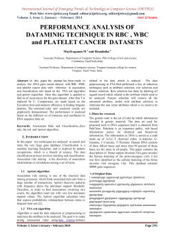


© Copyright 2026