
How to Emulate the Super Saw Bachelor of Science Thesis
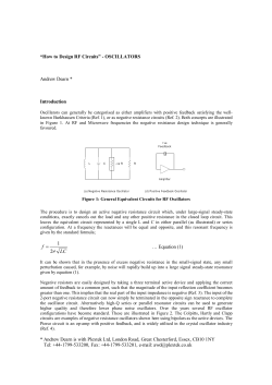
How to Emulate the Super Saw
ADAM
SZABO
Bachelor of Science Thesis
Stockholm, Sweden 2010
How to Emulate the Super Saw
ADAM
SZABO
Bachelor’s Thesis in Media Technology (15 ECTS credits)
at the Degree Programme in Media Technology
Royal Institute of Technology year 2010
Supervisor at CSC was Alex Jonsson
Examiner was Daniel Pargman
TRITA-CSC-E 2010:131
ISRN-KTH/CSC/E--10/131--SE
ISSN-1653-5715
Royal Institute of Technology
School of Computer Science and Communication
KTH CSC
SE-100 44 Stockholm, Sweden
URL: www.csc.kth.se
ABSTRACT
Analysis of the Super Saw was done in order to provide a detailed understanding of this special
oscillator found in the Roland JP-8000 and JP-8080. There are currently no software synthesizers
available which have the Super Saw oscillator or any faithful recreations which could represent this
special oscillator. With the results and findings in this thesis, it will be possible to emulate the Super
Saw on different platforms with great accuracy. No source code or any other copyrighted
techniques from the Roland synthesizers were used, therefore the recreation of the Super Saw is
strictly an emulation.
Samples of the Super Saw oscillator from the Roland JP-8000/JP-8080 synthesizer were recorded
with various settings. The samples were recorded at 44100Hz, 32Bit Stereo, to provide a high
quality analysis with the help of a spectrum analyzer and an oscilloscope. Four different aspects of
the Super Saw were taken into account and analyzed: the detune control, mix control, shape of the
oscillators, and phase of the oscillators. To emulate the Super Saw, the visual programming
environment: Outsim SynthMaker was used, because if its ease of use and flexibility. Matlab was
used to handle the data from the samples, and the curve fitting tool provided functions that
represent the different behaviors of the Super Saw accurately.
Analysis of different detune settings showed that the detune curve of the seven oscillators in the
Super Saw is not linear and the detune values do not result in a proportional ratio of detune
amount. An 11th order polynomial curve was derived from the acquired data, accurately
reproducing the actual detune curve. The mix control that changes the amplitude of the six
oscillators relative to the center oscillator turns out to be different than showed in the manual of
the synthesizer. The center oscillator decreases in volume in a linear fashion, where as the six other
oscillators increase with a shape of a parabola. The shape of the oscillators, are found to be actual
sawtooth waveforms, however, there is a high pass filter at the fundamental harmonic of the
waveforms which is “pitch tracked” that is, it follows the frequency of the first harmonic of the
oscillator. To prevent the oscillators from aliasing at higher frequencies, the high pass filter
removes the unwanted harmonics that are folded back into the audible spectrum below the set
frequency. The phases of the oscillators are strictly random, meaning the oscillators are free
running. Each note trigger produces a random value for the phase input of the oscillator, and
assigns it for each note trigger.
HUR MAN EMULERAR EN SUPER SAW
SAMMANFATTNING
I denna rapport har Roland Corporation's Super Saw oscillator analyseras med avsikt att ge läsaren
djupare kunskap för denna ganska speciella ljudoscillator som finns representerad i Rolands syntar
JP-8000 och JP-8080. Det finns för närvarande ingen mjukvarusyntes som korrekt återger en Super
Saw oscillator eller kan emulera denna särskilda oscillator med tillräcklig precision att den liknar
originalet. Med resultaten och slutsatserna i denna avhandling, är det möjligt att emulera Super Saw
på
en
generisk
ljudplattform
med
stor
noggrannhet.
Ingen
källkod
eller
annat
upphovsrättsskyddade metoder från Roland Corporation har använts, då ljudet återskapas av Super
Saw som en matematisk modell, uppbyggd av standardkomponenter.
Samplingar av Super Saw oscillator från Roland JP-8000/JP-8080 synthen spelades in med olika
inställningar. Ljuden är samplade i 44100 Hz, 32-bitars stereoformat, för att ge en hög kvalitet vid
analysen med hjälp av en spektrumanalysator och ett oscilloskop. Fyra olika parametrar som är
tongivande för att skapa Super Saw ljudets karaktär har beaktats och analyserats: ”detune”
kontrollen, ”mix” kontrollen, oscillatorernas form och fasförskjutning. För att simulera Super Saw,
den visuella programmeringsmiljön användes Outsim SynthMaker på grund av dess
användarvänlighet och flexibilitet. Programmet Matlab användes för att hantera data från
samplingarna, samt kurvanpassning för att finna funktioner som representerar de olika beteenden
på kontrollerna.
Analys av olika ”detune” inställningar, visar att kurvans utseende skapat av de sju oscillatorer i
Super Saw representerar inte ett linjärt förhållande mellan ökning av parameterns värde och
mängden interferens. Ett polynom av 11:e graden användes för att mate representera den samplade
detune kurvan. ”Mix” kontrollen som ändrar amplituden av de sex oscillatorerna i förhållande till
den sjunde referensoscillatorn, visar sig i rapporten vara annorlunda utformad än den som beskrivs
i manualen från Roland. Den centrala oscillatorn minskar i volym på ett linjärt sätt, medan de sex
andra oscillatorerna ökar i form av en parabelfunktion. Formen på oscillatorers individuella
karakteristik uppvisar sågtandsliknande vågformer, dock med ett högpassfilter som följer
vågformens grundton – filtrets arbetsområde drivs av värdet av oscillatorns basfrekvens. För att
förhindra oscillatorerna att ge upphov till missljudande aliasingfenomen vid högre frekvenser,
nyttjar Super Saw ett högpassfilter som tar bort oönskade övertoner som ”viker tillbaka” ner över
det hörbara frekvensområdet vid uppspelning av ljudet. Faserna hos varje oscillator varierar
slumpmässigt (eng: ”free running”), och varje not som spelas skapas av sju slumpmässiga bidrag,
ett varje enskild oscillator.
TABLE OF CONTENTS
1. INTRODUCTION ............................................................................................... 1
2. EXPERIMENTAL METHODS ......................................................................... 3
2.1 TARGET GROUP .......................................................................................................... 5
2.2 DELIMITATIONS ......................................................................................................... 6
3. THE SUPER SAW ................................................................................................ 7
3.1 DETUNE .......................................................................................................................... 8
3.2 MIX ...................................................................................................................................13
3.3 SHAPE .............................................................................................................................16
3.4 PHASE .............................................................................................................................20
4. CONCLUSIONS ................................................................................................ 23
4.1 DISCUSSION.................................................................................................................24
4.2 FUTURE WORK ..........................................................................................................27
5. REFERENCES.................................................................................................... 28
6. ACKNOWLEDGEMENTS ................................................................................ 29
1. INTRODUCTION
Early synthesizers in the analog era only used one oscillator that could be controlled. After the
discovery of layering several oscillators together and detuning them around a primary tone which
gave a much richer and warmer sound, many synthesizers started featuring multiple oscillators.
When digitalization became increasingly popular in the 90’s, Roland, the already established
synthesizer developer was one of the first to take advantage of this technology in their hardware.
Digital oscillators were much more flexible than analog ones, and it allowed greater possibilities in
creating sound. It was possible to layer even more oscillators together than before, and the concept
of the Super Saw: layering seven sawtooth oscillators together, was first realized by Roland’s JP8000 synthesizer in 1997. The unique sound it produced was popularized by modern electronic
music, and many famous artists and bands have used the Super Saw, like Jean Michelle Jarre,
Depeche Mode and The Pet Shop Boys.
Even after a decade, the Super Saw sound is equally sought after by people all around the world.
Some music genres like trance is based heavily on the Super Saw, and it was thanks to this sound
that made trance what it is today and it plays a crucial role in the overall sound of the music with
rich pads and ambiences. Unfortunately, this tool is not accessible for everyone, because the Super
Saw oscillator is currently only available in hardware synthesizers. The Roland models which
feature the Super Saw are: JP-8000, JP-8080, V-Synth, SH-201 and the recent Gaia SH-01. These
are expensive, and have lots of disadvantages compared to virtual instruments that are available
today.
As computers become increasingly powerful, more and more synthesizer and audio effect
developers realize the potential of software and port their hardware onto the computer platform.
Example companies are Korg, Lexicon and Novation who all have legacy products converted to
software equivalents. This gives significant advantage over their counterparts as the former have no
physical components which needs to be manufactured and therefore it is cheaper, has no risk of
breaking down, and it is easier to update. At the time of writing this thesis, there is no official
software equivalent of the Super Saw oscillator. Those who cannot afford a Roland synthesizer
which provide the Super Saw must look for alternative methods to produce this sound.
There have been many attempts to emulate the Super Saw sound with various techniques.
Sampling was very limited because once it was recorded there was no further possibility to modify
1
the properties of the oscillator. There have also been efforts to imitate the Super Saw in software
synthesizers or virtual instruments like the Supersaw Plus1, U-He Zebra22, Lennar Digital
Sylenth13, but cannot be considered a true emulation, because they sound and behave different.
The most accurate and similar method of recreating a Super Saw is called the Hyper Saw which is
an oscillator type featured in the Access Virus TI, 4 allowing the user to control and set the detune
for nine oscillators. The Super Saw has seven oscillators and the Hyper Saw is considered superior
because of its additional two oscillators, but it is still missing that characteristic sound that only the
Roland synthesizers have. With all these different solutions to imitate the Super Saw, it proves that
even today, the sound is very popular and there is a general interest to have this sound available in
software form.
When new solutions arrive that claim to emulate the Super Saw, people complain that they are not
good enough, and do not represent the real sound. The characteristics are not the same and it
sounds different. But why are the other attempts not authentic enough? What is missing from
those methods? What makes the Super Saw oscillator so special and why has there not been any
satisfying emulations before? This thesis investigates and aims to provide an answer to these
questions and presents solutions on how to emulate the Super Saw accurately. It is important to
emphasize that emulation is the means to produce a similar result with alternative means than the
original method, in the case of this thesis, using standard audio modules as building blocks
provided by the programming environment, therefore no source code, or any other copyrighted
material is violated.
2
2. EXPERIMENTAL METHODS
There were different methods and techniques used to emulate the Super Saw. Samples were
recorded from the synthesizers and analyzed with various tools. The analyzed samples were
converted to data points and compared to the software equivalent, and were adjusted to match the
original data. The procedure of the methods for recreating the Super Saw was:
●
Sampling
●
Analysis
●
Data collection
●
Comparison
●
Emulation
In order to gain a deeper insight into the nature and characteristics of the Super Saw, it has been
sampled and analyzed. Recording and analyzing the samples rather than opening and reverse
engineering each individual component of the synthesizer, eases the repeatability of the tests and
helps publish the results for everyone to see. If the components are identified, and reverse
engineered, patented technologies and copyrights might be violated, and therefore the software can
no longer be called an emulation. The recordings provide an open medium and a controlled
environment.
The synthesizers that were used to record the Super Saw samples were a Roland JP-8000 and a JP8080. Only these two models were used because no other Roland synthesizer was accessible. Since
the newer Roland hardware that feature a Super Saw, are all based on the original Super Saw from
the JP-8000, it is safe to assume that the recordings from these early models accurately represent
the overall Super Saw sound, even when compared to the modern incarnations of the synthesizers.
Each sample was recorded at 44100Hz, 32Bit Stereo in order to provide a high quality waveform,
which is non destructive and has minimal quality loss. Both the detune and mix controls were
sampled with different settings to show the behavior of these controls and to see how they modify
the properties of the oscillator. With the recorded samples, it was possible to break down the Super
Saw into its individual components: detune, mix, shape, phase and analyzed separately. The analysis
was done with an FFT spectrum analyzer to be able to examine the harmonics of the sound, and
an oscilloscope to look at the single cycle waveform the Super Saw generates. The resolution of the
3
FFT spectrum analyzer was set to 131072 points which gave a very accurate estimation of the
individual frequencies of the harmonics in the sound. The amplitude scale was also set to linear
when analyzing the mix control, to show the minor differences in the amplitude of the harmonics.
The data that was gathered was brought into Matlab and plotted, and the curve fitting tool was
used to derive a formula which replicates the behavior of the different controls. In some cases,
higher order polynomials were necessary, to accurately simulate the formulas that go through all
the data points.
The visual programming environment Outsim SynthMaker was used to carry out the experiments
to emulate the Super Saw because of its ease of use, flexibility, and constant updates which make it
a stable platform, but the results will be presented in a manner which will allow the solutions to be
reproducible in any programming environment.
4
2.1. TARGET GROUP
The main target groups for this thesis are synthesizer developers, who are interested in porting
hardware synthesizers into software. These people will benefit from the results that are presented,
in order to create a more accurate Super Saw emulation. With this knowledge, they can also come
up with new and exciting techniques to make the Super Saw, or use it to create something
completely. Sound designers might also find it interesting to learn more about the Super Saw, to
better understand how it works, and see why many synthesizers are not capable of creating an
accurate emulation of this sound. The thesis might also be of interest to people who have been
fans of the sound for a long time, but never knew how it is made or to people who claim that the
Super Saw is very easy to recreate. They will find out that it is not so simple and there are various
properties that make it special.
5
2.1. DELIMITATIONS
The thesis does not cover the disadvantages of SynthMaker and how it affects the outcome of the
results. The results and methods are provided in a matter, which can be adapted to every
programming platform, therefore the weakness or strength of a specific software to create the
emulation is not interesting. For example, a random number generated in SynthMaker can be
dateable if the number is truly random. Because SynthMaker uses single precision floating-point
format, there is limit in the range of the resulting number. Generating a truly random number in
software can be a thesis of its own, and therefore goes beyond the scope of the thesis.
Another limitation was having test subjects listen to the comparisons of audio from the original
Super Saw and the ones from the results, and rate the accuracy of the emulation. A test like this is
not feasible because there are always individuals with extreme opinions, like people who are against
software regardless of how well it sounds, blindly believing in that hardware always sounds better
than software. It was too problematic because there were no groups found who are not biased
towards the results and have a natural point of view with no expectations. Gathering a large
enough amount of people to represent a valid and plausible result, while very interesting, would
have been beyond the reach of the thesis, given limited time for conducting the study.
6
3. THE SUPER SAW
The Super Saw oscillator present in the Roland synthesizers is created by layering seven sawtooth
oscillators5, and tuning their frequency apart from each other by a set amount, causing the resulting
sound to sound “thick” and more “powerful”. It is especially used for creating string-type sounds,
and pads. Once the Super Saw is selected to be the active oscillator, the user can change two sets of
controls, which alters the behavior of the sound: detune and mix.
The detune knob on the synthesizer controls how much the oscillators will be de-tuned from each
other, by increasing the frequency offset from one another. There is a center oscillator which
governs the other six oscillators, and is not affected by the detune amount. It is always set to a
frequency defined by the overall tuning and notes played on the synthesizer. Three of the detuneable six oscillators will have higher, and three will have lower frequencies than that of the center
oscillator.
The mix knob adjusts the volume of the detuned oscillators relative to the center oscillator. As the
mix knob is increased, the detuned oscillators become louder, making the Super Saw sound more
apparent.
The detune and mix, are not the only features of the Super Saw that make it special. The shape
and phase of the oscillators also contribute to the unique sound which makes the Super Saw
oscillator have its own character. Each one of these properties must be carefully analyzed
separately for one to be able to recreate an authentic sound that matches the quality of the original
Super Saw.
7
3.1. DETUNE
The detune amount of the oscillators in the Super Saw is the most significant aspect of its typical
sound. If different frequencies are used in the individual oscillators, it will spread them apart from
the central oscillator. It is the amount of offset in the frequencies that determines one of the
fundamental characteristics of the sound. When the detune control is set to 0, the six oscillators
will have the same frequency as the center oscillator. But how much will the oscillators shift away
from each other when the detune is not zero, or when is set to maximum?
By analyzing a fully detuned Super Saw through a spectrum analyzer, it is possible to calculate the
offset of each frequency, and model a formula for the behavior of the detune control. The
fundamental harmonics of the oscillators are revealed as the detune is set to maximum (figure 1).
Figure 1: Maximum detune at C5 note (523 Hz)
The spectrum shows that the center oscillator is at 523.3572 Hz playing a C5 note, and the six
other oscillators have been detuned by a set value. This value cannot be defined by a frequency,
because the interval in an octave has half or double of its frequency. A number must be found
which can be used to detune the oscillators by the same amount regardless of the current
frequency.
To find this number, one must look at the relationship of the six oscillators with respect to the
center oscillator. The center oscillator must always be “1”, because it will have to be multiplied by
the frequency of the played note. If each oscillator is divided by the center oscillator, the
relationship between them is found, however, since the six oscillators must have the same
frequency as the center oscillator when the detune value is 0, it must be written in the form: 1+offset. This offset is then multiplied by the detune value which has to have the range from 0 to 1. If
8
the detune value is 0, all the offsets will also be 0 making the overall detune amount 1, thus having
the same frequency as the center oscillator (table 1).
Oscillator nr.
1
2
3
4 (center osc.)
5
6
7
Frequency (Hz)
465.7758
490.4462
513.1394
523.3572
533.7784
555.8919
579.5932
Division by center osc.
465.7758 / 523.3572 =
490.4462 / 523.3572 =
513.1394 / 523.3572 =
523.3572 / 523.3572 =
533.7784 / 523.3572 =
555.8919 / 523.3572 =
579.5932 / 523.3572 =
Relation
0.88997686 =
0.93711560 =
0.98047643 =
1=
1.01991221 =
1.06216538 =
1.10745242 =
1 +- offset
1 - 0.11002313
1 - 0.06288439
1 - 0.01952356
1+0
1 + 0.01991221
1 + 0.06216538
1 + 0.10745242
Table 1: Frequency of each oscillator. The relation is found and written in the form: 1+- offset
Once the offset values are multiplied by the detune value, and set to maximum, the distribution of
the oscillators in the frequency range, will have the same spectra as the Super Saw (figure 2).
Figure 2: The spectrum of the actual detune of the Super Saw, and the detune from the results.
When the detune value is 0, the detune amount of the individual oscillators will all be 1. This
means, that the oscillators will preserve their relation to the center oscillator regardless of the note
frequency. As the detune control is increased and its value reaches 1, the relation of the oscillators
becomes apparent in figure 3. With these results the detune amount is proportional to the detune
value, that is, when the detune value is set to half, the value of the offsets will also be half.
However, when using this model, and the detune value is set to half, the offset of the frequencies
in the oscillators are much higher than that of the Super Saw at the same detune value (figure 4).
This suggests that the formula of the detune is not proportional (figure 5), and requires further
analyzing to be able to see what happens with the curve.
9
Figure 3: Proportional detune of the oscillators.
Figure 4: Detune from the results compared to the Super Saw when detune is at half.
Figure 5: The detune curve cannot be linear because the change in the detune amount is not constant.
10
To reproduce the curve of the detune, sample points were taken at different detune intervals, and
comparing those results with the proportional curve provided enough data to be able to derive a
function which had a similar behavior as the detune used by the Super Saw.
Since the Roland JP-8000 is a hardware synthesizer, it uses MIDI protocol to transfer control data.
MIDI values are from a scale of 0 to 127 (128 in total). The detune of the Super Saw is therefore
divided into 128 steps. If the detune is sampled at every 8th interval, it will result in a total of 17
(value 0 also included) data points. These points must be converted to match the scale of the
detune scale that resulted from figure 3. Once the scale is from 0 to 1, the detune of the
proportional model can show the actual value of the detune amounts of each interval, when
analyzed and matched to the spectrum of the Super Saw (table 2). At every sample point the detune
amounts are compared, and the proportional detune is set to the sampled value.
When the converted MIDI values and the
MIDI
value
0
7
15
23
31
39
47
55
63
71
79
87
95
103
111
119
127
Conversion
0 / 127 =
7 / 127 =
15 / 127 =
23 / 127 =
31 / 127 =
39 / 127 =
47 / 127 =
55 / 127 =
63 / 127 =
71 / 127 =
79 / 127 =
87 / 127 =
95 / 127 =
103 / 127 =
111 / 127 =
119 / 127 =
127 / 127 =
Values
from 0-1
0
0.055118
0.118110
0.181102
0.244094
0.307086
0.370078
0.433070
0.496062
0.559055
0.622047
0.685039
0.748031
0.811023
0.874015
0.937007
1
Actual values
actual detune amounts are plotted against
0
0.00967268
0.0220363
0.0339636
0.0467636
0.0591273
0.0714909
0.0838545
0.0967273
0.121527
0.147127
0.193455
0.243418
0.2933815
0.343345
0.3928
1
each other, it becomes apparent that the
Table 2: The MIDI intervals are converted to a scale of 0 to 1
and their actual value is obtained using the linear detune.
curve is not proportional (figure 6).
Figure 6: Real detune values at every 8th interval.
With this data, it is possible to approximate a curve that will serve as a function with the help of
Matlab. The function will take the linear scale as the input (x), and it will return the approximate
values that correspond to the actual detune amount (y). To have a high enough approximation with
minimal amount of error, the function needs to be of at least a 10 degree polynomial. Let “data1”
be the converted MIDI values, and “data2”, the actual detune values. When both data is added to
Matlab and an 11th degree polynomial is approximated with the help of the polyfit function:
polyfit(data1,data2,11) the coefficients are listed, and gives the function:
11
y = (10028.7312891634*x^11)-(50818.8652045924*x^10)+(111363.4808729368*x^9)(138150.6761080548*x^8)+(106649.6679158292*x^7)-(53046.9642751875*x^6)+(17019.9518580080*x^5)(3425.0836591318*x^4)+(404.2703938388*x^3)-(24.1878824391*x^2)+(0.6717417634*x)+0.0030115596
When the function is graphed (figure 7), it goes
through all the data points and estimates the values
between them. The curve only has a slight increase
until the detune value reaches 0.5, where it turns
steeper, and has a drastic rise after 0.9. If the
detune behavior has this property, the offset of the
frequencies in each oscillator will be very little,
even when the detune control on the synthesizer is
turned up very high. This is plausible, because
Figure 7: The 11th degree polynomial through the data
points.
when the oscillators are only slightly detuned from
each other, it is possible to create string-like sounds
which the Super Saw was mainly used for.
Figure 8: Comparisons of the linear detune and the actual detune.
When the function is applied to the detune, and compared to the proportional value of each
oscillator (figure 8), the true behavior of the detune in the Super Saw becomes apparent. This
behavior, allows for a precise control, and fine-tuning of the frequencies.
12
3.2. MIX
A very unique feature of the Super Saw is the mix function, which other synthesizers claiming to
do the Super Saw do not have. This essentially allows the user to control the volume of the detuneable oscillators relative to the center oscillator. The Access Virus TI’s Hypersaw, allows one
oscillator to be heard alone; however it adds the oscillators’ volumes one by one, instead of all of
them at the same time.
The manual6 of the Roland JP-8000 explains that the mix control will increase the amplitude of the
oscillators to be the same level as the center oscillator. In reality, this is not the case. When the
spectrum of a fully detuned Super Saw was analyzed, and two samples were compared, one with
the mix control set to 0 and one set to 127, it showed that the center oscillator actually decreased in
amplitude. If the oscillators are numbered from 1 to 7, 4 will be the center oscillator. When the mix
control was at maximum, oscillators 1-3 and 5-7, did not reach the amplitude of the center
oscillator, and oscillator 4 was decreased in volume (figure 9).
Figure 9: Comparisons of mix at 0, and mix at 127.
To get an approximation of the behavior of the oscillators when the mix control is used, the mix in
the Super Saw was sampled, at every 8th interval, providing 17 data points. This showed that the
center oscillator decreases in a proportional fashion and the side oscillators gain amplitude in the
form of an arc. To demonstrate this, each sample was analyzed using the same settings, and the
resulting graphs of the harmonics were layered on top of each other. To aid the presentation, the
13
harmonics of the oscillators 2, 3 and 5-7 were removed. Oscillators 1-3 and 5-7 have different
amplitudes but since they behave the same way, oscillator 1 represents their activity. Each layer of
the graph was shifted right, to show them separate from each other. This method revealed how the
amplitude of the center and side oscillators changed with different mix settings (figure 10).
Figure 10: Each analyzed sample is shifted right revealing the true nature of the amplification..
The sampled audio was analyzed and the ratio of difference in amplitude of both the side and
center oscillators were recorded, and put in table 3. The MIDI values were converted to 0-1 scale.
MIDI
value
0
7
15
23
31
39
47
55
63
71
79
87
95
103
111
119
127
Conversion
0 / 127 =
7 / 127 =
15 / 127 =
23 / 127 =
31 / 127 =
39 / 127 =
47 / 127 =
55 / 127 =
63 / 127 =
71 / 127 =
79 / 127 =
87 / 127 =
95 / 127 =
103 / 127 =
111 / 127 =
119 / 127 =
127 / 127 =
Values
from 0-1
0
0.055118
0.118110
0.181102
0.244094
0.307086
0.370078
0.433070
0.496062
0.559055
0.622047
0.685039
0.748031
0.811023
0.874015
0.937007
1
Center osc.
values
1
0.965
0.93
0.901
0.86
0.83
0.795
0.76
0.72
0.69
0.65
0.62
0.585
0.55
0.51
0.48
0.445
Side osc.
values
0.03836
0.12
0.19
0.25
0.31
0.37
0.42
0.46
0.5
0.53
0.56
0.58
0.59
0.6
0.605
0.6
0.59
Table 3: MIDI values of different mix settings and center and side oscillator settings.
14
The plotted data confirmed what figure 10 showed. The center oscillator decreases in a straight
line, where as the side oscillators gain amplitude in a shape of a parabola (figure 11). A curve fitting
method of the plotted data produced a first degree polynomial for the center oscillator where “x”
represents the mix control input, and “y” the change in amplitude as the output:
y = -0.55366*x + 0.99785
And a second degree polynomial for the side oscillators:
y = -0.73764*x^2 + 1.2841*x + 0.044372
Figure 11: Plot of data and approximated functions.
The purpose of this change in amplitude is to prevent the Super Saw from being too loud. Because
the 6 side oscillators are increased in gain, the overall volume of the total 7 oscillators needs to be
lowered to prevent distortion. It is interesting to note that the oscillators have the same volume at
the 0.75 mark, that is, when the mix control is at value 95, contrary to the maximum value stated in
the manual.
15
3.3. SHAPE
The oscillators in the Super Saw are commonly known to be sawtooth waveforms. The name itself
implies that the oscillators are saw shaped, hence the name Super “Saw”. Being able to find out the
waveform of an oscillator when it is layered with additional waveforms is relatively hard. It is not
possible to see the shape of each oscillator (even though their shape is the same) because when
their amplitudes are summed, it creates a new waveform, and masks the original source. In the case
of the Super Saw however, it is possible to see the waveform of a single oscillator, because when
the mix control is set to 0, the volume of the detuned oscillators are lowered, minimizing their
amplitude and only the central oscillator is heard, therefore it is possible to be analyzed.
A normal saw waveform ramps upward, and drops at a sharp angle. (figure 12 a), nevertheless, the
shape of the saw found in the Super Saw (figure 12 b) looks very different when viewed through an
oscilloscope.
Figure 12: a. Ordinary sawtooth wave. b.saw from the Super Saw.
Why do the two waveforms look so unlike? Why do the saw shaped oscillators from the Super Saw
look different and are they really saw waveforms? What is the purpose and function of such a
shape?
Research showed that oscillators used in the Super Saw are in fact saw oscillators, but the added
signal of the 7 waveforms goes through a high pass filter. A way to achieve such a waveform
without a high pass filter is through a wavetable oscillator. This method cannot be the one used by
the Super Saw, because a wavetable oscillator is band limited, and the oscillators found in the Super
Saw are not. A wavetable oscillator has information about the amplitude of each harmonic within
16
the oscillator. It cannot have unlimited amount of harmonics, because it would take too much
information to store all the data. Because of this, the harmonic information is limited, and when
the oscillator is playing a low note, the upper frequencies are cut off, and it will lack presence and
clarity (figure 13 a). The oscillators of the Super Saw do not have this problem, so they must be
standard sawtooth waveforms (figure 13 b).
Figure 13: a. wavetable oscillator. b. standard saw oscillator.
If the oscillators are generated sawtooth waveforms, this will result in aliasing. The harmonics that
are above the Nyquist frequency in other words, half the sampling frequency, the harmonics of the
oscillators are folded back into the audible range, causing digital artifacts and noise. This drawback
in digital oscillators turns to its advantage in the Super Saw, because the noise adds an extra layer of
depth to the sound, causing it to sound more full and airy. The noise however, does not sound
pleasant below the fundamental harmonic, because it will sound unnatural and disturbing. To
prevent this, a high pass filter can be used to remove the unwanted frequencies in the noise, if the
filter is always at the first harmonic of the sound (figure 14).
Figure 14: A high pass filter is used to cut the noise below the fundamental harmonic.
17
The spectrum of the Super Saw shows that the noise is cut below the fundamental harmonic,
suggesting that there is a high pass filter after the oscillators as in figure 15.
Figure 15: Noise is cut using a high pass filter.
If the scale of the amplitude in the spectrum analyzer is linear, the minor difference in the volume
of each harmonic is emphasized. When viewing a fully detuned Super Saw with a linear scale in the
amplitude, the first harmonic of each oscillator becomes gradually louder (figure 16).
Figure 16: Gradual increase in amplitude of the first harmonic.
If the individual oscillators would have different volumes, the gradual increase in the amplitude
would be the same in every harmonic, but since this is not the case, there must be a high pass filter
at the end of the signal. The fact that only the first harmonics are gradually increasing, is direct
evidence to support this assumption.
18
Because the filter is always set to follow the pitch of the oscillators, the fundamental harmonics are
reduced by a small amount, causing the saw oscillator to look like the oscillator from the Super Saw
(figure 17).
Figure 17: a. Oscillator from Super Saw b. Oscillator from results. c. Comparison of oscillators.
When the high pass filtered sawtooh oscillator is compared with the oscillator from the Super Saw
with an oscilloscope (figure 17 c), the result looks extremely similar to the original, which means
that the filter is used correctly.
19
3.4. PHASE
The phase of an oscillator or wave denotes the offset of the displacement in the cycle of the
oscillator at a particular point in time. It is normally not an audible characteristic of a single wave,
however when multiple waves with either different or same phases are combined, their amplitudes
are summed to create a new wave and the interference of their phase can cause it to have different
behavior depending on the offset of the phase. Because the Super Saw combines seven oscillators,
the phase of the oscillators in the Super Saw, play a particularly crucial role in how the sound
changes with each note trigger.
When the Super Saw is playing a single note repeatedly, the difference in each note can be seen
through a recording, displayed in the time domain. Each note looks different implying that the
phases of the oscillators are constantly varying (figure 18). Because the detune and amplitude are
always constant, the phase must be the only variable that is changing, causing the waves to look
dissimilar. This effect is most evident, when the detune of the oscillators are small, causing very
little offset in the frequencies, creating the irregular motion in the amplitude of the waves.
Figure 18: Recording of a Super Saw playing the same note repeatedly with low detune amount.
Oscillators that do not have a static phase are known as a “free-running oscillators”. A new phase
value to each wave is assigned for every note trigger, creating an asymmetrical wave each time.
Figure 18 suggests that the Super Saw uses this method, because each note looks different. If the
oscillators are not free-running, the phases of the oscillators are retriggered and reset to their
original value (which could be the same or different for each oscillator), causing the waveform to
look the same for each trigger.
Consider a case where four oscillators are being used: a, b, c, and d. Their amplitudes are the same,
and their frequencies are slightly offset. When their respective phase is reset, the amplitude of their
initial cycle will superimpose the sound of each oscillator, thereby causing a very high gain in
20
amplitude. As the frequencies are slightly different, their wavelength will be longer, and their cycle
will drift away from one another each time a note is played, resulting in a “flanging” effect (figure
19)
Figure 19: The oscillators are reset, causing a flanging effect.
If the phases of the oscillators are offset, the gain in amplitude of the initial cycle will not be
present, but it will still sound the same with every note trigger, when they are reset back to the
specified offset (figure 20).
Figure 20: The phase for each oscillator has an offset, but they still reset.
To achieve a sound that is typical to the Super Saw, the waveform must never be the same. The
phase must receive a value that is different every time a note is triggered (figure 21).
Figure 20: Random values are assigned to the phase at each note trigger.
When the phase values are assigned randomly to each oscillator at every note trigger, it will result in
an irregular waveform which will add motion to the sound making it more interesting and organic.
A low frequency oscillator could also be used to modulate the phase, however results showed that
21
the phase must be static throughout the trigger hold for the best effect. If the phase is modulated,
it will be in motion throughout the trigger event, and it will cause unwanted irregularities and
artifacts to the sound.
22
4. CONCLUSIONS
The results of the research, and experiments showed that the Super Saw is a very complex and
unique sound, with properties not found in any other recreations. The analysis proved that there
are four different aspects of the Super Saw that define its special sound, and where it greatly differs
from other imitations: the phase of the oscillators, detune of the oscillators, the mix control and the
high pass filter at the end of the signal.
To emulate the Super Saw, the phase of the oscillators must be random. Each note trigger must
assign a random value to the phase causing it to be different each time, which will make the sound
more organic and natural. The detune of the oscillators must be very subtle to produce pad sounds
typical to the Roland JP-8000, and the narrow slope of the detune curve half way in the detune
control, provides the ability to achieve such sounds. Another great factor is the aliasing of the
oscillators which is considered a bad artifact within an oscillator and purposely removed in other
synthesizers. Aliasing automatically occurs with all digitally generated oscillators and adds digital
noise to the signal, but ironically, this artifact provides “airiness” to the sound, and because of that,
the Super Saw will have a brighter tone. Oscillators that are clean of this artifact, such as wavetable
oscillators can be made to have digital noise with “bit crushers” or subtle distortion. The high pass
filter is used to remove the unwanted and harsh noise below the fundamental frequency of the
oscillator, while letting the higher frequency noise to complement the overall sound. The mix
control that changes the amplitude of the detune-able oscillators must also be controlling the
central oscillator at the same time, lowering its amplitude by a small amount, as the mix is
increased.
All of these discoveries of the various properties of the Super Saw contribute to its unique and
special sound, which allows for the possibility to translate these results into software. Schematics
figure 21 and figure 22, show the logic of the Super Saw emulation and the structure of the
different elements. The oscillators used in the schematic are standard saw oscillators with frequency
and phase inputs. They enter the Mix module where the central oscillator (Osc. 4), and the side
oscillators amplitudes are modified according to the mix control. The signal is then combined and
sent through a high pass filter to remove the unwanted noise and digital artifacts.
23
S u p e rS aw m o d u le
F re q u e nc y
D e tu n e
Trig g e r
M ix
H ig h p a s s filte r
A u d io
F re q .
F re q u e nc y
In p u t
D e tu n e c o n tro l
In p u t
A u d io s tre a m
O u tp u t
1 1 th ord e r fu nc tio n
D e tu n e
N o te trig g e r
In p u t
M ix c o n tro l
In p u t
Figure 21: The Frequency, Mix, and note trigger all go into the Super Saw module. The detune control goes through the 11th
order function to have the correct detune amount. The audio signal is fed through a high pass filter to remove the unwanted noise.
D e tu n e m o d u le
F re q u e nc y
In p u t
F re q .
D e tu n e
D e tu n e c o n tro l
In p u t
O sc . 1
F re q .
Ph ase
O sc . 2
F re q .
Ph ase
O sc . 3
M ix m o d u le
O sc . 1
O sc . 2
O sc . 3
O sc . 4
O sc . 5
O sc . 6
O sc . 7
M ix
A u d io s tre a m
O u tp u t
F re q .
Ph ase
O sc . 4
F re q .
Ph ase
O sc . 5
N o te trig g e r
In p u t
Ran d o m
p h ase
m o d u le
Trig g e r
F re q .
Ph ase
O sc . 6
F re q .
Ph ase
O sc . 7
F re q .
Ph ase
M ix c o n tro l
In p u t
Figure 22: Inside the Super Saw module. The main frequency is modified by the detune input in the Detune module, and outputs
the offset for each oscillator. Random phase values are assigned to the oscillators when the note trigger is active. The output of the
oscillators enters the Mix module, where their amplitude is combined and modified by the mix control.
24
4.1. DISCUSSION
The solutions presented in the thesis provide the possibility to create a very accurate emulation of
the Super Saw, and shows information on how to achieve this sound. With the knowledge gained,
the questions raised in the introduction are now possible to answer.
What makes the Super Saw so special? Why are the other attempts at recreating the Super Saw not
authentic enough and what is missing from those methods? The previous imitations that are
available have all claimed to be inspired by the Super Saw, but showed no satisfying results. They
fail to understand how the Super Saw is actually made and make use of knowledge based on
rumors and vague descriptions. Since the Super Saw oscillator is a selling factor of the Roland
synthesizers, very little is revealed about it, and even in the operation manual, only the necessary
basics are discussed. The lack of information forced developers to rely on their ears and supposed
methods that are spread on discussion boards and forums. Because there are no proper imitations,
it shows that no one has gone to great length to deeply analyze the Super Saw and make an
accurate emulation, therefore missing the essence and real properties of the sound. One of the
main factors that distinguish the Super Saw from other attempts is the very important detune
curve, which gives a very unique behavior for the detune control of the oscillator. The mix control
is also missing in other attempts, which is a crucial control in the Super Saw. The aliasing which
gives a unique character to the sound is also not present in previous imitations. The only property
that seems to be the same in other synthesizers is the randomness of the phases in the oscillators. It
is one of the most audible effect in the character of the Super Saw, and since the user has no
control over this, it is important to get it right.
But why has there not been any overall satisfying emulation made yet? One of the reasons could be
that there might be younger audience/producers who have never actually heard a real Super Saw
from an original Roland synthesizer before, and therefore have no reference on how it actually
sounds, therefore approving of the already existing imitations that they sound “good”. In most
cases, only people who have owned or heard and gotten familiar with the original Super Saw can
hear the difference between the real sound and an imitation. Because of this, the developers might
assume that their existing methods are close enough and needs no further work. Another reason
why there has not been any official emulation from Roland could be due to piracy. Having the
Super Saw sound in hardware form ensures that it cannot be pirated. It is true that piracy is a great
problem on the internet, and causes a problem to all software products. There have been
25
numerous solutions against this problem that failed, and could be the reason why Roland still
refuses to port their hardware into software. In recent years however, USB licenses, or dongles
have proven to be a safe protection against piracy and theft. If the Super Saw would be available in
a virtual instrument, it will have great advantages over the hardware synthesizers. It will be cheaper
to produce and distribute, saving fuel and also being more eco friendly. The main advantages are:
●
no need to transport physical synthesizer, less weight to carry, therefore saving fuel.
●
no need to produce additional materials and components, therefore much cheaper.
●
does not use additional power supply, runs inside computer, saving electricity.
●
components do not degrade over time and no risk of damage, no need to repair.
●
developers can provide the software as a downloadable product, therefore no need to print
manual or burn to CD.
●
easier to update, and improve.
Although not perfect, synthesizers in software have their own disadvantages:
●
does not have “hands on” control, and harder to edit
●
not possible to play live on stage
●
risk of crashing: if computer fails so does the synthesizer
Some of these problems however do have solutions, like using a midi controller to control the
virtual synthesizer, and therefore becomes easier to edit, or using a midi keyboard to play notes,
making it possible to play the software live. In the end, it is up to the user to decide which
compromises are more important, and chooses accordingly.
If the Super Saw is available as software, it will be accessible to everyone, to those who could not
afford a Roland synthesizer before, or to those that have migrated to software only and do no
longer use hardware synthesizers in their setup. An authentic emulation means it will provide us
with a better understanding on how to achieve the classic Super Saw, and inspires the possibility to
combine the knowledge gained, with new techniques used today in modern synthesizers.
26
4.2. FUTURE WORK
Suggestions for further work include investigating the delimitations of the thesis, and provide
answers to the problems which have not been studied.
Because SynthMaker uses single precision floating-point format to compute and handle numbers, it
is questionable how accurate the results were. In future tests, the emulation could be conducted
with a different programming environment which uses double precision floating-point format, and
investigating how much difference there is between the resulting sounds. Examining the random
number generator in SynthMaker, and studying other means of generating a number is another
topic that could be covered. Finding previous research about random number generators, and
adapting those methods for the phase of the oscillators could provide even better results.
To prevent the audio comparison tests from being biased, a blindfold test could have been
conducted, where instead of telling the used which sample is the original; A/B comparisons could
be made. Will there be a case where someone might choose the emulation to be the original sound?
Future studies could provide an answer.
27
5. REFERENCES
(1) http://homepage.ntlworld.com/sealed/newwebsite/supersaw.htm
(2) http://www.u-he.com/zebra/
(3) http://www.lennardigital.com/modules/sylenth1/index.php
(4) http://www.virusti.com/
(5) http://en.wikipedia.org/wiki/Roland_JP-8000
(6) Roland Corporation; JP-8080 Owner’s Manual; 1998
28
6. ACKNOWLEDGEMENTS
I would like to express my special thanks to my supervisor Alex Jonsson. Thank you for help,
useful comments and ideas that made my thesis better.
Thank you Chris Breame for giving me a hand with your Roland JP, and the interesting discussions
we had about the Super Saw.
Thanks to Nadine, Semu and Fatema for their friendship, help, and support over the years in
KTH.
29
TRITA-CSC-E 2010:131
ISRN-KTH/CSC/E--10/131--SE
ISSN-1653-5715
www.kth.se


© Copyright 2026