
How to Implement the Freescale MPL115A Digital Barometer Freescale Semiconductor Application Note
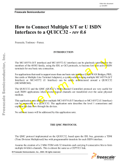
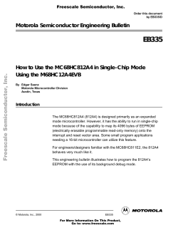
AN3785
Rev 2, 4/2009
Freescale Semiconductor
Application Note
How to Implement the Freescale MPL115A
Digital Barometer
by: John Young and Tom Ohe
INTRODUCTION
MPL115A is a simple barometer with digital output and high performance targeting low cost commercial applications. The
device employs a MEMS PRT pressure sensor with a conditioning IC to provide accurate pressure data. The sensor output is
accurate to ±1 kPa over the 50 kPa to 115 kPa pressure range. An integrated ADC provides digitized temperature and pressure
sensor outputs via an I2C or SPI bus. The part’s operating voltage is from 2.375 V to 5.5 V. The part is available as either an I2C
or SPI part. The customer can order the device in either bus protocol depending on which is more convenient for their end
application.
Calibration data is housed in on-board ROM. This data is used by a host microcontroller to apply a compensation algorithm to
the raw ADC data from the pressure sensor and may be accessed at any time. The Calibration data is stored as a series of
coefficients that are applied to the raw data to compensate for temperature and pressure variation in the raw output.
The following application note will describe the SPI and I2C protocol needed to communicate to the digital pressure sensor.
Following communication and extraction of the stored coefficients, raw data from the sensor’s PRT can be compensated on the
host microcontroller for pressure and temperature. The application note details this process and the end result of the calculation
is Compensated Pressure.
Sample Boards:
Freescale has two sample eval boards available in either SPI or I2C MPL115A device variations. These are simple PCB boards
with sensor parts, associated pull-up resistors and decoupling capacitors soldered onboard for customer evaluation. This
provides a quick sample tool to run evaluations for the small device given its LGA footprint.
U1
1
VDD
CAP 2
4
1.0UF
7
1
CAP
SHDN
SCLK
CS
8
5
DIN
DOUT
6
GND
VDD1
VDD
C1
3
C2
GND1
SCL/SCLK
RS/CS
NC/Dout
MPL115A1
1.0UF
1
SDA/Din
SHDN/TEST
VDD
A
B
4
3
2
1
1
2
0.1UF
3
C3
SW1
J4
Figure 1. SPI MPL115A Interface Board
© Freescale Semiconductor, Inc., 2008, 2009. All rights reserved.
VDD
R3
4.70 K
U1
R1
4.70 K
R2
4.70 K
1
VDD
VDD
1.0 UF
7
1
SCLK
CS
8
5
DIN
DOUT
6
C2
3
GND1
J1
CAP
SHDN
GND
VDD1
CAP 2
4
VDD
C1
SCL/SCLK
1
2
HDR_1X2
MPL115A2
1
1.0 UF
SDA/Din
SHDN/TEST
VDD
1
A
2
B
0 .1UF
3
C3
SW1
Figure 2. I2C MPL115A Interface Board
PRODUCT FEATURES
• Low Cost: A low enough cost base for the part will enable several consumer markets that presently cannot use this function
on cost grounds. Low cost is key to the success of the part.
• Small Size: 1.2 mm maximum height. Footprint as small as possible.
• Low Power: The part spends most its life in standby mode and is woken by a host micro when a measurement is needed.
Overall current consumption of a few μA is needed to be attractive to handheld applications.
• Moderate Accuracy: Target (compensated) accuracy is 1kPa over as much temperature range as possible. The part is
specified for operation from -40°C to 105°C but may have reduced accuracy at these temperature limits.
ABSOLUTE MAXIMUM RATINGS
Voltage (with respect to GND unless otherwise noted)
VDD .............................................................................................................................. -0.3 V to +5.5 V
SCLK, CS, DIN, DOUT ................................................................................................. -0.3 V to VDD+0.3 V
Operating Temperature Range .................................................................................... -40°C to +105°C
Storage Temperature Range........................................................................................ -40°C to +125°C
AN3785
Sensors
Freescale Semiconductor
2
ELECTRICAL CHARACTERISTICS
(VDD = 2.375 V to 5.5 V, TA = -40°C to +105°C, unless otherwise noted. Typical values are at VDD = 3.3 V, TA = +25°C.
Ref
Parameters
Symbol
1
Operating Supply Voltage
VDD
2
Supply Current
IDD
Conditions
Min
Typ
Max
Units
2.375
3.3
5.5
V
Shutdown (SHDN = GND)
—
—
1
μA
Standby
—
3.5
10
μA
Average – at one measurement per second
—
5
TBD
μA
Pressure Sensor
3
Range
50
—
115
kPa
4
Resolution
—
—
—
kPa
5
Accuracy
-20ºC to 85ºC
—
±1
—
kPa
6
Conversion Time
(Start Pressure Convert)
Time between start convert command and
data available in the Pressure register
—
3
—
ms
-40
—
105
ºC
tcp
Temperature Sensor
7
Range
8
Conversion Time
(Start Temperature Convert)
tct
Time between start convert command and
data available in the Temperature register
—
3
—
ms
9
Conversion Time
(Start Both Convert)
tcb
Time between start convert command and
data available in the Pressure and
Temperature registers
—
3
—
ms
[1]
—
—
8
MHz
SPI Inputs: SCLK, CS, DIN
10
SCLK Clock Frequency
f SCLK
11
Low Level Input Voltage
VIL
—
—
0.3VDD
V
12
High Level Input Voltage
VIH
0.7 VDD
—
—
V
V
SPI Outputs: DOUT
13
14
Low Level Output Voltage
High Level Output Voltage
VOL1
At 3 mA sink current
0
—
0.4
VOL2
At 6 mA sink current
0
—
0.6
VOH1
At 3 mA source current
VDD – 0.4 V
—
—
V
NOTES:
1. Nominal maximum SPI clock frequency.
AN3785
Sensors
Freescale Semiconductor
3
PIN DESCRIPTION (I²C/SPI)
PIN
NAME
1
VDD
VDD Power Supply Connection.
VDD range is 2.375 V to 5.5 V.
FUNCTION
2
CAP
External Capacitor
Output decoupling capacitor for main internal regulator. Connect a 10 F capacitor to ground.
3
GND
Ground
4
SHDN/TST
Shutdown
Connect to GND to disable the device. When in shut down the part draws <1 μA supply current and all
communications pins (RST/CS, SCL/SCLK, SDA/DOUT, NC/DIN) are high impedance. Connect to VDD for
normal operation.
Also functions as Programming/test input: connect to voltage above VDD to enter test mode.
5
RST/CS
Reset bar (I2C) / CS (SPI)
I2C devices: Drive line low to disable I²C communications. I²C pins are high impedance and communications
are ignored. All internal functions operate normally.
6
NC/DOUT
SPI devices: SPI Chip Select line. See SPI communications section for details.
NC (I2C) / DOUT (SPI)
I2C devices: No connection.
SPI devices: Serial data output.
During analog debug mode (see special functions register) this pin is used to convey the output of the analog
test mux. All devices are 3-wire SPI only when in analog debug mode.
7
SDA/DIN
SDA (I2C) / DIN (SPI)
I2C devices: Serial data I/O line.
SPI devices: Serial data input.
Debug mode: 3-wire SPI DIN/DOUT line.
8
SCL/SCLK
I2C/SPI Serial Clock Input.
PIN CONFIGURATION
VDD
1
8
SCL/SCLK
CAP
2
7
SDA/DIN
GND
3
6
NC/DOUT
SHDN/TST
4
5
RST/CS
Figure 3. Top View
NOTE: Pinout is subject to change. Pinout change may only be made under consultation with the product definer.
AN3785
Sensors
Freescale Semiconductor
4
DETAILED DESCRIPTION
The MPL115A barometer provides low cost pressure measurement for consumer electronics where altitude barometric
measurements are required.
The system comprises a pressure sensor and a conditioning IC housed within a low profile package. The conditioning IC
contains a temperature sensor together with an ADC and some ROM for coefficient storage. Two, test configurable, versions of
the part provide simple I2C or SPI slave interface functions. A low resolution (10b) SAR or algorithmic type converter is used. The
host microcontroller communicates with MPL115A via the I2C or SPI port and performs the calculations necessary to obtain
calibrated pressure from the raw ADC values.
MPL115A uses standardized calculation algorithms to determine pressure using the temperature and pressure ADC output
values together with stored coefficient values.
reg
reg
M
MUX
Diff
Ampl
10-bit
A/D
reg
reg
pressure
temp
I2C/SPI
reg
Temp
Sensor
Compensation
block
10-bit
D/A
Figure 4. Block Diagram
AN3785
Sensors
Freescale Semiconductor
5
BASIC OVERVIEW OF FUNCTIONS/OPERATION
MPL115A will interface to a host (or system) microcontroller in the customer’s application. All communications are via I2C or
SPI. A typical usage sequence is as follows:
Initial Power Up
All circuit elements are active. I2C/SPI port pins are high impedance and associated registers are cleared. On conclusion of
the startup routine the main system circuits shut down leaving the part in standby “wake on I2C” mode or, in the case of SPI
devices, in the communication mode determined by the CS line.
The customer may assert RST to disable the I2C port while other system peripherals are initialized. RST only affects the I2C
block and does not affect other blocks. The I2C address register is not affected by RST. If a full chip reset is needed then this
must be accomplished by power cycling the part.
Similarly, when using the SPI version, Chip Select (CS) only controls communications and does not reset the part.
Reading Coefficient Data
The user then typically accesses the part and reads coefficient data. The main circuits within the slave device are disabled
during read activity. The coefficients are typically stored in host micro local memory but can be uploaded at any time. The part
always enters standby mode at the conclusion of the start-up routine or conversion activity.
For longer periods of inactivity the user may assert the SHDN input (drive input low). This removes power from all internal
circuits, including any registers. The registers are then reloaded when SHDN is driven high.
Data Conversions
These are initiated by sending the start pressure convert, start temperature convert or start both convert request via I2C/SPI.
The main system circuits are activated (wake up) in response to a valid start conversion command. The required conversion is
initiated once the sensor and internal circuits have stabilized. This is typically 3 ms in the Electrical Characteristics table for sensor
stabilization time. The result of the conversion is placed in the appropriate register (Pressure, Temperature or both) and the main
circuits shut down again. The user must then wait the required wait time before reading the conversion result(s). The typical wait
time is 3 ms associated with each conversion type.
Compensated Pressure Reading
The host microcontroller manipulates the stored coefficient data with the now incoming changing pressure and temperature
data. Utilizing a standard equation (detailed later) data is manipulated for compensation and the raw pressure and temperature
data now becomes the current barometric/atmospheric pressure. Remember that this is an absolute pressure measurement with
a vacuum as a reference.
Communications
MPL115A normally operates as either an I2C or SPI slave device depending on the condition of the communications bit in the
setup register. Special use cases: test and debug force the part into a predetermined mode.
I2C Interface
I2C mode MPL115A operates as an I2C slave capable of bus speeds up to 400 kbits/sec (Fast Mode). MPL115A uses 7-bit
addressing, does not acknowledge the general call address 0000000, and does not perform clock stretching. The current address
set up on the MPL115A is 0101100.
The I2C port pins SDA and SCL are compatible with the full supply voltage range. Data is written to and read from the device
in bit sequence as 8-bit blocks.
AN3785
Sensors
Freescale Semiconductor
6
Write Mode
I²C writes to the device are conducted using normal I²C protocol. An I²C start condition is followed by the 7-bit slave address
and Write bit. The slave acknowledges the write request and latches the following data byte from the master. Further bytes are
ignored when in normal (user) mode. A stop or repeat start condition must be sent by the master to complete the sequence. User
mode write commands consist of start convert commands for pressure, temperature or both. These commands are shown in
Table 2. An example of the user mode I²C write sequence is shown in Figure 5.
7 bit slave address
Plus WRITE bit
8 bit command
S D D D D D D D W Ack 0 0 X X X X X X Ack
P
MASTER TO SLAVE
SLAVE TO MASTER
Stop bit (or repeated Start)
signifies end of transmission.
Figure 5. I²C Write Sequence – User Mode
Read Mode
I²C reads from the device are conducted using normal I²C protocol.
To read from the device the master must first send a data address or command that points to the required data. To do this the
master sends the 7-bit slave address + Write bit followed by data address byte. Transmission is initiated by an I²C start condition
and ended by either a Repeated Start or a Stop condition. The master then resends the 7-bit slave address, this time with a Read
bit, either directly following the Repeated Start condition or, if the previous transmission ended with a Stop condition, preceded
by an I²C start condition.
The slave acknowledges each byte received and proceeds to send the requested data following receipt of the second slave
address. The slave continues to send data, incrementing the address pointer at the end of each byte. The master acknowledges
receipt of each byte sent by the slave and asserts a Stop (or Repeated Start) condition at the conclusion of the transmission.
Examples of I²C reads for pressure data (2 bytes) and coefficient data (up to 12 bytes) are shown in Figure 6 and Figure 7.
10-bit pressure and temperature data is transmitted MSB first with trailing zeros. This allows the user to read only the first byte
in systems that do not require the full resolution of the part and may only have limited processing capability. The device continues
to send data until either the transmission is complete or the master either issues a stop condition or fails to assert an acknowledge
bit i.e. the slave treats a “Nak” (not acknowledge) as a stop bit. The master thus controls the amount of data it receives and
discards any data that is not needed.
7 bit slave address
Plus WRITE bit
“Read Pressure MSB”
command
7 bit slave address
Plus READ bit
10 bit pressure data
with trailing zeros
S D D D D D D D W Ack X 0 0 0 0 0 0 0 Ack Sr D D D D D D D R Ack P P P P P P P P Ack P P 0 0 0 0 0 0 Nak*
MASTER TO SLAVE
P
Stop bit signifies end of transmission.
Slave stops sending data immediately.
SLAVE TO MASTER
* The standard termination sequence is “Nak” followed by the stop condition. An “Ack” followed by the stop condition
may also be used.
Figure 6. I²C Read Pressure Sequence
AN3785
Sensors
Freescale Semiconductor
7
7 bit slave address
Plus WRITE bit
7 bit slave address
Plus READ bit
“Read Coefficient 1”
command
Coefficient data
First Byte
S D D D D D D D W Ack X 0 0 0 0 1 0 0 Ack Sr D D D D D D D R Ack A A A A A A A A Ack
B B B B B B B B Ack C C C C C C C C Ack
Coefficient data
Second Byte
Ack Z Z Z Z Z Z Z Z Nak*
Coefficient data
Third Byte
P
Coefficient data
Final Byte
MASTER TO SLAVE
Stop bit signifies end of transmission.
Slave stops sending data immediately.
SLAVE TO MASTER
* The standard termination sequence is “Nak” followed by the stop condition. An “Ack” followed by the stop condition
may also be used.
Figure 7. I²C Read Coefficients Sequence
I²C Bus Timing
Data is valid on the SDA line while the SCL line is stable and high. The slave may only change the state of SDA line while SCL
is low. This is typically controlled by the falling edge of SCL.
Timing of the SCL and SDA lines is shown in Figure 8.
SDA
tBUF
tSU:DAT
tSU:ST
tLOW
tHD:DAT
tHD:ST
tSU:SP
SCL
tHIGH
tHD:ST
tR
START CONDITION
tF
START CONDITION
STOP
CONDITION
START
CONDITION
Figure 8. I²C Bus Timing
I²C RST
The I²C RST function prevents the I²C circuits from drawing power while the I²C inputs are active. Ideally this is accomplished
by removing power from the I²C I/O circuits. The part ignores I²C communications when RST is asserted and does not draw
additional power due to transitions on the I²C connections. Drive line low to disable I²C communications. I²C pins are high
impedance and communications are ignored. If RST is asserted during an I²C transmission then the transmission is aborted (and
lost). All other internal functions operate normally. No other functions or registers are reset as a result of asserting this function.
SPI Interface
In SPI mode MPL115A operates as a half duplex 4-wire SPI slave capable of bus speeds up to 8 Mb/sec.
AN3785
Sensors
Freescale Semiconductor
8
SPI 4-Wire Mode
4 lines make up the SPI interface: SCLK, DIN, DOUT and CS. Data is read from the port in 2 byte sequence: address byte
plus Read/Write bit received on DIN followed by data byte transmitted on DOUT. Write commands are a 2 byte sequence:
address byte plus Read/Write bit followed by data byte, both received on DIN. Exceptions to this are the “action” addresses e.g.
“Start Pressure Conversion”, “Start Temperature Conversion” etc. The interface is half duplex and so cannot receive and transmit
simultaneously. A figure for minimum data setup time (interval between command receipt and data ready on DOUT) is given in
the Electrical Characteristics table. This is typically 3 ms for setup time.
SPI transfers to and from the part are controlled by the CS line. CS is driven low by the master at the start of communication
and held low for the duration of the two byte transfer.
SPI data transfers occur on the rising edges of SCLK. Data on the DIN and DOUT lines is changed on the falling edges of
SCLK and clocked on the rising edges of SCLK: the rising edges provide the “data valid” condition.
Driving CS high places DOUT in a high impedance state. DOUT remains high impedance while CS is high. DOUT is held low
while CS is low and there is no transmission activity on DOUT.
The next data transfer commences on the next CS high to low transition.
4-Wire Mode
CS
SCLK
DIN
SDI
R /W A[5] A[4] A[3] A[2] A[1] A[0]
DOUT
SDO
D[7] D[6] D[5] D[4] D [3] D [2] D[1] D[0]
Figure 9. SPI Read Operation
CS
SCLK
DIN
SDI
R/W A[5] A[4] A[3] A[2] A[1] A[0]
D[7] D[6] D[5] D[4] D [3] D [2] D[1] D[0]
Figure 10. SPI Write Operation
DEVICE READ WRITE OPERATIONS
All device read/write operations are memory mapped. Device actions e.g. “Start Pressure Conversion” are controlled by writing
to the appropriate memory address location. All memory address locations are 6-bit (see Table 5). A read/write bit (SPI) and a
“don’t care” bit(s) are added to make up the total number of bits to 8.
For I2C devices the MSB (bit 7) is “don’t care” and bits 6 to 0 are available for addressing e.g. bit 6 is always 0 with the
remaining bits (5:0) making up the 6-bit address in MPL115A.
For SPI devices the MSB is R/W and the LSB is “don’t care” with the remaining bits (6:1) making up the 6-bit address. The
appropriate memory location is written to/read from in response to the condition of the R/W bit which is ‘1’ for read operations
and ‘0’ for write operations.
The basic device write commands are shown in Table 1 (SPI versions) and Table 2 (I2C versions). The availability of particular
commands depends on the operating mode of the device. There are three basic operating modes: Test, Debug and User
(normal).
AN3785
Sensors
Freescale Semiconductor
9
Table 1. SPI Write Commands
8-bit code
Mode
Bus type
Start Pressure Conversion
Command
0010000X
All
SPI
Start Temperature Conversion
0010001X
All
SPI
Start both Conversions
0010010X
All
SPI
X = don’t care
Table 2. I2C Write Commands
8-bit Code
Mode
Bus Type
Start Pressure Conversion
Command
X0010000
User
I 2C
Start Temperature Conversion
X0010001
User
I 2C
Start both Conversions
X0010010
User
I 2C
X = don’t care
The actions taken by the part in response to each command is as follows:
Command
Action Taken
Start Pressure Conversion
Wake up main circuits. Start clock. Allow supply stabilization time. Select pressure sensor
input. Apply positive sensor excitation and perform A to D conversion. Latch result in ADC S1
register. Apply negative sensor excitation and perform A to D conversion. Latch result in ADC
S2 register. Load the Pressure register with the result of ADC S1 – ADC S2 – P offset. Shut
down main circuits and clock.
Start Temperature Conversion
Wake up main circuits. Start clock. Allow supply stabilization time. Select temperature input.
Perform A to D conversion. Latch result in ADC S1 register. Invert temperature sense signal
and perform A to D conversion. Latch result in ADC S2 register. Load the Temperature
register with the result of ADC S1 – ADC S2 – T offset. Shut down main circuits and clock.
Start Both Conversions
Wake up main circuits. Start clock. Allow supply stabilization time. Select pressure sensor
input. Apply positive sensor excitation and perform A to D conversion. Latch result in ADC S1
register. Apply negative sensor excitation and perform A to D conversion. Latch result in ADC
S2 register. Load the Pressure register with the result of ADC S1 – ADC S2 – P offset. Select
temperature input. Perform A to D conversion. Latch result in ADC S1 register. Invert
temperature sense signal and perform A to D conversion. Latch result in ADC S2 register.
Load the Temperature register with the result of ADC S1 – ADC S2 – T offset. Shut down
main circuits and clock.
SPI Read operations are performed by sending the required address with a leading Read bit. SPI operations require that each
byte is addressed individually. During I2C transfers the device increments the address pointer after each byte such that
continuous bytes may be read from the device in address sequence. Table 3 (SPI versions) and Table 4 (I2C versions) show
some basic read commands. All data is transmitted MSB first.
Table 3. Example SPI Read Commands
Command
8-bit Code
Mode
Bus Type
Read Pressure Hi byte
1000000X
All
SPI
Read Pressure Lo byte
1000001X
All
SPI
Read Temperature Hi byte
1000010X
All
SPI
Read Temperature Lo byte
1000011X
All
SPI
Read Coefficient data byte 1
1000100X
All
SPI
X = don’t care
AN3785
Sensors
Freescale Semiconductor
10
Table 4. Example I²C Read Commands
8-bit code
Mode
Bus type
Read Pressure Hi byte
Command
X0000000
User
I 2C
Read Pressure Lo byte
X0000001
User
I 2C
Read Temperature Hi byte
X0000010
User
I 2C
Read Temperature Lo byte
X0000011
User
I 2C
Read Coefficient data byte 1
X0000100
User
I 2C
X = don’t care
DEVICE MEMORY MAP
Table 5. Device Memory Map
Address
Name
Description
Size
(bits)
Accessibility (mode)
NVM
User
Test
Debug
$00
POUTH
10-bit pressure output value MSB
8
Yes
Yes
Yes
$01
POUTL
10-bit pressure output value LSB
2
Yes
Yes
Yes
$02
TOUTH
10-bit temperature output value MSB
8
Yes
Yes
Yes
$03
TOUTL
10-bit temperature output value LSB
2
Yes
Yes
Yes
$04
COEF1
96-bit coefficient data 1st byte
8
8
Yes
Yes
Yes
$05
COEF2
96-bit coefficient data 2nd byte
8
8
Yes
Yes
Yes
$06
COEF3
96-bit coefficient data 3rd byte
8
8
Yes
Yes
Yes
$07
COEF4
96-bit coefficient data 4th byte
8
8
Yes
Yes
Yes
$08
COEF5
96-bit coefficient data 5th byte
8
8
Yes
Yes
Yes
$09
COEF6
96-bit coefficient data 6th byte
8
8
Yes
Yes
Yes
$0A
COEF7
96-bit coefficient data 7th byte
8
8
Yes
Yes
Yes
$0B
COEF8
96-bit coefficient data 8th byte
8
8
Yes
Yes
Yes
$0C
COEF9
96-bit coefficient data 9th byte
8
8
Yes
Yes
Yes
$0D
COEF10
96-bit coefficient data 10th byte
8
8
Yes
Yes
Yes
$0E
COEF11
96-bit coefficient data 11th byte
8
8
Yes
Yes
Yes
$0F
COEF12
96-bit coefficient data 12th byte
8
8
Yes
Yes
Yes
$10
PRESS
Start Pressure Conversion
Yes
Yes
Yes
$11
TEMP
Start Temperature Conversion
Yes
Yes
Yes
$12
BOTH
Start both Conversions
Yes
Yes
Yes
AN3785
Sensors
Freescale Semiconductor
11
SPI TIMING
Table 6 and Figure 11 describe the timing requirements for the SPI system.
Table 6. SPI Timing
No.
Function
Operating Frequency
Symbol
Min
Max
Unit
—
—
8
MHz
1
SCLK Period
tSCLK
125
—
ns
2
SCLK High time
tCLKH
62.5
—
ns
3
SCLK Low time
tCLKL
62.5
—
ns
4
Enable lead time
tSCS
125
—
ns
5
Enable lag time
tHCS
125
—
ns
6
Data setup time
tSET
30
—
ns
7
Data hold time
tHOLD
30
—
ns
8
Data valid (after SCLK low edge)
tDDLY
—
32
ns
9
Width CS High
tWCS
30
—
ns
Figure 11. SPI Timing Diagram
COMPENSATION
The pressure compensation for MPL115A is based on a 2-dimensional, second order polynomial based on Microsystems
mst_trimlib library.
The 10-bit compensated pressure output for MPL115A, Pcomp, is calculated as follows:
Pcomp = a0 + (b1 + c11*Padc + c12*Tadc) * Padc + (b2 + c22*Tadc) * Tadc
Where:
• Padc is the 10-bit pressure output of the MPL115A ADC,
• Tadc is the 10-bit temperature output of the MPL115A ADC,
• a0 is the pressure offset coefficient,
• b1 is the pressure sensitivity coefficient,
• c11 is the pressure linearity (2nd order) coefficient,
• c12 is the coefficient for temperature sensitivity coefficient (TCS),
• b2 is the 1st order temperature offset coefficient (TCO),
• c22 is the 2nd order temperature offset coefficient.
Ideally, Pcomp will produce a value of 0 with an input pressure of 50 kPa and will produce a full-scale value of 1023 with an
input pressure of 115 kPa.
AN3785
Sensors
Freescale Semiconductor
12
EVALUATION SEQUENCE, ARITHMETIC CIRCUITS
The following is a possible sequence for the calculation Pcomp, the trimmed pressure output. Input values are in bold.
c11x1 = c11 * Padc
a11 = b1 + c11x1
c12x2 = c12 * Tadc
a1
= a11 + c12x2
c22x2 = c22 * Tadc
a2
= b2 + c22x2
a1x1 = a1 * Padc
y1
= a0 + a1x1
a2x2 = a2 * Tadc
Pcomp = y1 + a2x2
This is just a succession of MACs of the form y = a + b * x:
a
b
+
y
+
×
y
x
The polynomial Pcomp = a0+(b1 + c11*Padc + c12*Tadc)*Padc + (b2 + c22*Tadc)*Tadc can be evaluated as a sequence of
5 MACs:
a
b1
c11
a11
x1
c12
a1
y1
b2
c22
a2
y
y
x2
AN3785
Sensors
Freescale Semiconductor
13
COEFFICIENT BIT-WIDTH SPECS
The table below specifies the initial coefficient bit-width specs for the compensation algorithm.
10-bit Output: Compensation Coefficient Specs
a0
b1
b2
c12
c11
c22
Total
Coeff.
Bits
Total Bits
16
16
16
14
11
11
84
Sign Bits
1
1
1
1
1
1
Integer Bits
12
2
1
0
0
0
Fractional Bits
3
13
14
13
11
10
dec pt zero
pad
-
-
-
9
11
15
Example Binary Format Definitions:
1.Sign = 0, Integer Bits = 8, Fractional Bits = 4 :
Coeff = S I7 I6 I5 I4 I3 I2 I1 I0 . F3 F2 F1 F0
2.Sign = 1, Integer Bits = 4, Fractional Bits = 7 :
Coeff = S I3 I2 I1 I0 . F6 F5 F4 F3 F2 F1 F0
3.Sign = 0, Integer Bits = 0, Fractional Bits = 6, dec pt zero pad = 2 :
Coeff = S 0 . 0 0 F5 F4 F3 F2 F1 F0
4.Sign = 0, Integer Bits = 0, Fractional Bits = 5, dec pt zero pad = 3 :
Coeff = S 0 . 0 0 0 F4 F3 F2 F1 F0
NOTE: Negative coefficients (Sign = 1) are coded in 2’s complement notation.
The coefficients derived from mst_trimlib are designed to add no more than 1 LSB of error relative to floating-point calculations.
The output bit widths of the intermediate calculations (c11x1, a11, etc.) should be fixed to 16-bits in order to limit the number of
operations using an 8-bit MCU, such as the S08. Simulations with Matlab using these fixed-point limits on the intermediate
calculations show the pressure specs can be met with Cpks > 2.
COEFFICIENT ADDRESS MAP
Address
Coefficient
$04
a0 MS Byte
$05
a0 LS Byte
$06
b1 MS Byte
$07
b1 LS Byte
$08
b2 MS Byte
$09
b2 LS Byte
$0A
c12 MS Byte
$0B
c12 LS Byte
$0C
c11 MS Byte
$0D
c11 LS Byte
$0E
c22 MS Byte
$0F
c22 LS Byte
For coefficients with less than 16-bits, the lower LSBs are zero. For example, c11 is 11-bits and is stored into 2 bytes as follows:
c11 MS byte = c11[10:3] = [c11b10 , c11b9 , c11b8 , c11b7 , c11b6 , c11b5 , c11b4 , c11b3]
c11 LS byte = c11[2:0] & “00000” = [c11b2 , c11b1 , c11b0 , 0 , 0 , 0 , 0 , 0]
AN3785
Sensors
Freescale Semiconductor
14
//===================================================
//Coefficient 9 equation compensation
//===================================================
//
//Variable sizes:
//For placing high and low bytes of the Memory addresses for each of the 6 coefficients:
//signed char (S8) sia0MSB, sia0LSB, sib1MSB,sib1LSB, sib2MSB,sib2LSB, sic12MSB,sic12LSB, sic11MSB,sic11LSB, sic22MSB,sic22LSB;
//
//Variable for use in the compensation, this is the 6 coefficients in 16bit form, MSB+LSB.
//signed int (S16) sia0, sib1, sib2, sic12, sic11, sic22;
//
//Variable used to do large calculation as 3 temp variables in the process below
//signed long (S32) lt1, lt2, lt3;
//
//Variables used for Pressure and Temperature Raw.
//unsigned int (U16) uiPadc, uiTadc.
//signed (N=number of bits in coefficient, F-fractional bits)
//s(N,F)
//The below Pressure and Temp or uiPadc and uiTadc are shifted from the MSB+LSB values to remove the zeros in the LSB since this
// 10bit number is stored in 16 bits. i.e 0123456789XXXXXX becomes 0000000123456789
uiPadc=PressCntdec>>6; //Note that the PressCntdec is the raw value from the Pegasus data address. Its shifted >>6 since its 10 bit.
uiTadc=TempCntdec>>6; //Note that the TempCntdec is the raw value from the Pegasus data address. Its shifted >>6 since its 10 bit.
//******* STEP 1 c11x1= c11 * Padc
lt1 = (S32)sic11;
// s(16,27) s(N,F+zeropad) goes from s(11,10)+11ZeroPad = s(11,22) => Left Justified = s(16,27)
lt2 = (S32)uiPadc;
// u(10,0) s(N,F)
lt3 = lt1 * lt2;
// s(26,27)
/c11*Padc
si_c11x1 = (S32)(lt3);
// s(26,27)- EQ 1 =c11x1 /checked
//divide this hex number by 2^30 to get the correct decimal value.
//b1 =s(14,11) => s(16,13) Left justified
//******* STEP 2 a11= b1 + c11x1
lt1 = ((S32)sib1<<14);
// s(30,27)
b1=s(16,13) Shift b1 so that the F matches c11x1(shift by 14)
lt2 = (S32)si_c11x1;
// s(26,27) //ensure fractional bits are compatible
lt3 = lt1 + lt2;
// s(30,27)
/b1+c11x1
si_a11 = (S32)(lt3>>14); // s(16,13) - EQ 2 =a11 Convert this block back to s(16,X)
//******* STEP 3 c12x2= c12 * Tadc
// sic12 is s(14,13)+9zero pad = s(16,15)+9 => s(16,24) left justified
lt1 = (S32)sic12;
// s(16,24)
lt2 = (S32)uiTadc;
// u(10,0)
lt3 = lt1 * lt2;
// s(26,24)
si_c12x2 = (S32)(lt3);
// s(26,24) - EQ 3 =c12x2 /checked
//******* STEP 4 a1= a11 + c12x2
lt1 = ((S32)si_a11<<11); // s(27,24) This is done by s(16,13) <<11 goes to s(27,24) to match c12x2's F part
lt2 = (S32)si_c12x2;
// s(26,24)
lt3 = lt1 + lt2;
// s(27,24)
/a11+c12x2
si_a1 =(S32)(lt3>>11); // s(16,13) - EQ 4 =a1 /check
//******* STEP 5 c22x2= c22 * Tadc
// c22 is s(11,10)+9zero pad = s(11,19) => s(16,24) left justified
lt1 = (S32)sic22;
// s(16,30) This is done by s(11,10) + 15 zero pad goes to s(16,15)+15, to s(16,30)
lt2 = (S32)uiTadc;
// u(10,0)
lt3 = lt1 * lt2;
// s(26,30)
/c22*Tadc
si_c22x2 = (S32)(lt3);
// s(26,30) - EQ 5 /=c22x2
//******* STEP 6 a2= b2 + c22x2
//WORKS and loses the least in data. One extra execution. Note how the 31 is really a 32 due to possible overflow.
lt1 = ((S32)sib2<<15);
// b2 is s(16,14) User shifted left to => s(31,29) to match c22x2 F value
//s(31,29)
AN3785
Sensors
Freescale Semiconductor
15
lt2 = ((S32)si_c22x2>>1);
lt3 = lt1+lt2;
si_a2 = ((S32)lt3>>16);
//s(25,29) s(26,30) goes to >>16 s(10,14) to match F from sib2
//s(32,29) but really is a s(31,29) due to overflow the 31 becomes a 32.
//s(16,13)
//******* STEP 7 a1x1= a1 * Padc
lt1 = (S32)si_a1;
lt2 = (S32)uiPadc;
lt3 = lt1 * lt2;
si_a1x1 = (S32)(lt3);
// s(16,13)
// u(10,0)
// s(26,13)
/a1*Padc
// s(26,13) - EQ 7 /=a1x1 /check
//******* STEP 8 y1= a0 + a1x1
// a0 = s(16,3)
lt1 = ((S32)sia0<<10);
// s(26,13) This is done since has to match a1x1 F value to add. So S(16,3) <<10 = S(26,13)
lt2 = (S32)si_a1x1;
// s(26,13)
lt3 = lt1 + lt2;
// s(26,13)
/a0+a1x1
si_y1 = ((S32)lt3>>10);
// s(16,3) - EQ 8 /=y1 /check
//******* STEP 9 a2x2= a2 *Tadc
lt1 = (S32)si_a2;
lt2 = (S32)uiTadc;
lt3 = lt1 * lt2;
si_a2x2 = (S32)(lt3);
// s(16,13)
// u(10,0)
// s(26,13)
/a2*Tadc
// s(26,13) - EQ 9 /=a2x2
//******* STEP 10 pComp = y1 +a2x2
// y1= s(16,3)
lt1 = ((S32)si_y1<<10);
// s(26,13) This is done to match a2x2 F value so addition can match. s(16,3) <<10
lt2 = (S32)si_a2x2;
// s(26,13)
lt3 = lt1 + lt2;
// s(26,13)
/y1+a2x2
// FIXED POINT RESULT WITH ROUNDING:
siPcomp = ((S16)lt3>>13);
// goes to no fractional parts since this is an ADC count.
//decPcomp is defined as a floating point number.
//Conversion to Decimal value from 1023 ADC count value. ADC counts are 0 to 1023. Pressure is 50 to 115kPa correspondingly.
decPcomp = ((65.0/1023.0)*siPcomp)+50;
AN3785
Sensors
Freescale Semiconductor
16
How to Reach Us:
Home Page:
www.freescale.com
Web Support:
http://www.freescale.com/support
USA/Europe or Locations Not Listed:
Freescale Semiconductor, Inc.
Technical Information Center, EL516
2100 East Elliot Road
Tempe, Arizona 85284
1-800-521-6274 or +1-480-768-2130
www.freescale.com/support
Europe, Middle East, and Africa:
Freescale Halbleiter Deutschland GmbH
Technical Information Center
Schatzbogen 7
81829 Muenchen, Germany
+44 1296 380 456 (English)
+46 8 52200080 (English)
+49 89 92103 559 (German)
+33 1 69 35 48 48 (French)
www.freescale.com/support
Japan:
Freescale Semiconductor Japan Ltd.
Headquarters
ARCO Tower 15F
1-8-1, Shimo-Meguro, Meguro-ku,
Tokyo 153-0064
Japan
0120 191014 or +81 3 5437 9125
[email protected]
Asia/Pacific:
Freescale Semiconductor China Ltd.
Exchange Building 23F
No. 118 Jianguo Road
Chaoyang District
Beijing 100022
China
+86 010 5879 8000
[email protected]
For Literature Requests Only:
Freescale Semiconductor Literature Distribution Center
P.O. Box 5405
Denver, Colorado 80217
1-800-441-2447 or +1-303-675-2140
Fax: +1-303-675-2150
[email protected]
AN3785
Rev. 2
4/2009
Information in this document is provided solely to enable system and software
implementers to use Freescale Semiconductor products. There are no express or
implied copyright licenses granted hereunder to design or fabricate any integrated
circuits or integrated circuits based on the information in this document.
Freescale Semiconductor reserves the right to make changes without further notice to
any products herein. Freescale Semiconductor makes no warranty, representation or
guarantee regarding the suitability of its products for any particular purpose, nor does
Freescale Semiconductor assume any liability arising out of the application or use of any
product or circuit, and specifically disclaims any and all liability, including without
limitation consequential or incidental damages. “Typical” parameters that may be
provided in Freescale Semiconductor data sheets and/or specifications can and do vary
in different applications and actual performance may vary over time. All operating
parameters, including “Typicals”, must be validated for each customer application by
customer’s technical experts. Freescale Semiconductor does not convey any license
under its patent rights nor the rights of others. Freescale Semiconductor products are
not designed, intended, or authorized for use as components in systems intended for
surgical implant into the body, or other applications intended to support or sustain life,
or for any other application in which the failure of the Freescale Semiconductor product
could create a situation where personal injury or death may occur. Should Buyer
purchase or use Freescale Semiconductor products for any such unintended or
unauthorized application, Buyer shall indemnify and hold Freescale Semiconductor and
its officers, employees, subsidiaries, affiliates, and distributors harmless against all
claims, costs, damages, and expenses, and reasonable attorney fees arising out of,
directly or indirectly, any claim of personal injury or death associated with such
unintended or unauthorized use, even if such claim alleges that Freescale
Semiconductor was negligent regarding the design or manufacture of the part.
Freescale™ and the Freescale logo are trademarks of Freescale Semiconductor, Inc.
All other product or service names are the property of their respective owners.
© Freescale Semiconductor, Inc. 2009. All rights reserved.


© Copyright 2026