
How to Synchronize Multiple TPM Modules in HCS08 1 Introduction
Freescale Semiconductor
Application Note
Document Number: AN3581
Rev. 0, 02/2008
How to Synchronize Multiple
TPM Modules in HCS08
by: HaiNing Liu
Asia & Pacific Operation
Microcontroller Solutions Group
1
Introduction
Many HCS08 microcontrollers offer multiple
timer/pulse-width modulators (TPMs). Timer functions
are typically used in ways that require them to be related
to a single counter. This document explains how to
synchronize these TPMs so that all channels operate as if
they are related to a single counter.
© Freescale Semiconductor, Inc., 2008. All rights reserved.
Contents
1
2
3
4
Introduction . . . . . . . . . . . . . . . . . . . . . . . . . . . . . . . . . . .
TPM Module on HCS08. . . . . . . . . . . . . . . . . . . . . . . . . .
Synchronizing Multiple TPM Modules . . . . . . . . . . . . . . .
3.1 Synchronized using Software . . . . . . . . . . . . . . . . .
3.2 Counter Modes Study . . . . . . . . . . . . . . . . . . . . . . .
Conclusion. . . . . . . . . . . . . . . . . . . . . . . . . . . . . . . . . . . .
1
2
3
3
3
7
TPM Module on HCS08
2
TPM Module on HCS08
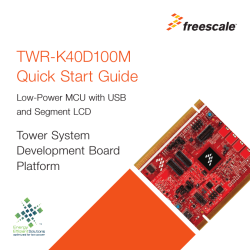
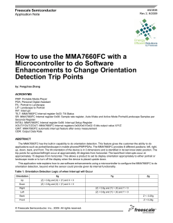
The TPM is very effective for general use and is common to all HCS08 products. Figure 1 shows the
structure of a TPM for the HCS08 family.
BUS CLOCK
FIXED SYSTEM CLOCK
SYNC
EXTERNAL CLOCK
CLOCK SOURCE
SELECT
OFF, BUS, FIXED
SYSTEM CLOCK, EXT
PRESCALE AND SELECT
³1, 2, 4, 8, 16, 32, 64,
or ³128
CLKSB:CLKSA
PS2:PS1:PS0
CPWMS
16-BIT COUNTER
TOF
COUNTER RESET
TOIE
INTERRUPT
LOGIC
16-BIT COMPARATOR
TPMxMODH:TPMxMODL
CHANNEL 0
ELS0B
ELS0A
PORT
LOGIC
TPMxCH0
16-BIT COMPARATOR
TPMxC0VH:TPMxC0VL
CH0F
16-BIT LATCH
MS0B
MS0A
CH0IE
INTERRUPT
LOGIC
Figure 1. TPM Architecture
The key component of the TPM module is a free running main 16-bit counter with an up/down counting
option. The TPM can use a 16-bit module register (TPMxMPDH: TPMxMODL) to control counter range
and generate a terminal count interrupt if the main counter matches the value of the modulus register.
The TPM includes several stand-alone channels. Each channel can be configured as input-capture mode,
output-compare mode, buffered-edge-aligned PWM mode, or center-aligned PWM mode. The channels
have the following flexibility:
• The input capture trigger can be rising-edge, falling-edge, or any-edge.
• The output compare function has set, clear, and toggle options.
• PWM outputs have selectable polarity.
• All channels can be configured to work at the same center-aligned PWM (CPWM) mode when
CPWMS bit in the TPMxSC register is set.
• Interrupt request can be enabled or disabled for each channel.
How to Synchronize Multiple TPM Modules in HCS08, Rev. 0
2
Freescale Semiconductor
Synchronizing Multiple TPM Modules
3
Synchronizing Multiple TPM Modules
The multiple TPMs on HCS08s provide the flexibility of multiple time bases, but many applications need
channels associated with a common time base. For example, we may combine two TPMs in MC9S08SH8
that will perform exactly like a single 4-channel TPM, so that count transitions occur at exactly the same
time in both TPMs.
3.1
Synchronized Using Software
The TPM has no external synchronizing/enable pins, but it can be enabled by setting either the CLKSB bit
or the CLKSA bit of TPMxSC, or both of these bits, to 1. It can be disabled by clearing these two bits.
Here we introduce a software synchronization method with the following assumptions. In other
applications, all of these assumptions must be included, but there may be others also.
• The clock sources are fixed to the bus clock, so we can enable TPM by setting the
CLKSB : CLKSA bit as 0 : 1.
• The prescale factor and modulus value of the combined TPMs must be the same.
• The count operation modes must be the same, either 16-bit free running (CPWMS = 0) or else
up/down (CPWMS = 1).
• To prevent interrupt in initializing, all interrupt sources must be disabled.
3.2
Counter Modes Study
Because there are two different counter modes — free running and up/down counting — the
synchronization implementation will be a little different for each one.
3.2.1
Free-Running Counter (CPWMS = 0)
As an up-counter, the main 16-bit counter counts from 0x0000 through its terminal count, and then starts
over at 0x0000. The terminal count will be updated by 0xFFFF or a modulus value in
TPMxMODH:TPMxMODL.
How to Synchronize Multiple TPM Modules in HCS08, Rev. 0
Freescale Semiconductor
3
Synchronizing Multiple TPM Modules
Pf * (Mc1 + 1)
AB
TPM1_modulus
E
Pf * (Mc + 1)
N
Pf * (Mc2 + 1)
Timing
(Bus_cycles)
TPM2_modulus
CD
E
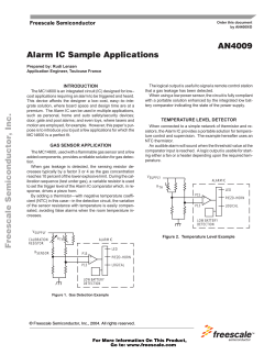
Figure 2. Synchronization Mechanism of Combined TPMs on Free-Running Counter
The synchronization process is listed below:
1. As shown in Figure 2, enable the TPM1 by initializing the TPM1SC register at time A. The
modulus counter starts to run at time B, several bus cycles after time A, because of the instruction
execution delay.
2. Enable the TPM2 at time C, and the modulus counter of TPM2 will actually start to run at time D.
If using the same assembly code, the instruction execute delay will be the same as for TPM1.
3. To compensate for the delay between TPM1SC write (time A) and TPM2SC write (time C), we
introduce Equation 1 to choose the modulus values of TPM1 and TPM2.
Mc2 = Mc1 – N / Pf
Eqn. 1
Here
— Mc2: the modulus value of TPM2
— Mc1: the modulus value of TPM1
— N: the bus cycle delay between TPM1SC write and TPM2SC write
— Pf: the desired prescale factor of TPM1 and TPM2.
4. Re-initialize the modulus value of TPM1 and TPM2 to the desired modulo setting (here named Mc)
before the first overflow time (time E). These two TPMs will be synchronized at this same Mc after
time E.
Try to choose smaller values for Mc1 and Mc2, which will have the advantage of making synchronization
time shorter (from time A to time E), but make sure to finish initializing these two modulus values during
this time interval (from time D to time E). Table 1 lists how to choose these parameters based on Pf. All
these parameters have been verified with the attached example project. Example 1 shows the code with
Pf = 16.
How to Synchronize Multiple TPM Modules in HCS08, Rev. 0
4
Freescale Semiconductor
Synchronizing Multiple TPM Modules
Table 1. Choose Mc1, Mc2, and N According to Different Values for Pf
Pf
Mc1
Mc2
N (Bus Cycles)
1
> 21
Mc1 – 4
4
2
> 11
Mc1 – 2
4
4
>5
Mc1 – 1
4
8
>3
Mc1 – 1
8
16
>2
Mc1 – 1
16
32
>1
Mc1 – 1
32
64
>1
Mc1 – 1
64
128
>1
Mc1 – 1
128
Example 1. Code for Pf = 16
asm{
MOV #$00,
TPM1MODH
MOV #$15,
TPM1MODL
MOV #$00,
TPM2MODH
MOV #$11,
TPM2MODL
LDA #$02;
MOV #$0c,
TPM1SC
Delay1_1:
NOP
DBNZA
Delay1_1
NOP;
NOP;
MOV #$0c,
TPM2SC
MOV #$03, TPM1MODH
MOV #$e8, TPM1MODL
MOV #$03, TPM2MODH
MOV #$e8, TPM2MODL
//initial Mc1
//initial Mc2
//Pf
= 16
//Pf = 16
// update to desired Mc
// update to desired Mc
}
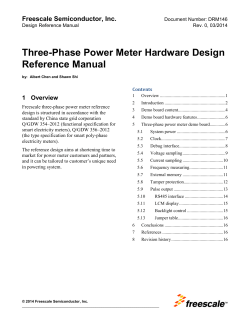
3.2.2
Up-Down Counter (CPWMS = 1)
When CPWMS = 1, the counter counts upward from 0x0000 through its terminal count, then counts
downward to 0x0000, where it returns to up-counting. The synchronization mechanism is similar to that
described in Section 3.2.1, “Free-Running Counter (CPWMS = 0).” The only difference is to choose
different values for Mc1 and Mc2 according to Equation 2.
Mc2 = Mc1 - N/ 2 / Pf
Eqn. 2
How to Synchronize Multiple TPM Modules in HCS08, Rev. 0
Freescale Semiconductor
5
Synchronizing Multiple TPM Modules
2 * Pf * Mc1
E
A B
TPM1_modulus
2 * Pf * Mc
N
2 * Pf * Mc2
Timing
(Bus_cycles)
TPM2_modulus
CD
E
Figure 3. Synchronization Mechanism of Combined TPMs in CPWM Mode
Table 2 lists how to choose these parameters according to Pf. All the data have been verified by using the
attached example.
Table 2. Choose Mc1, Mc2, and N According to Different Values for Pf
Pf
Mc1
Mc2
N (Bus Cycles)
1
> 18
Mc1 – 2
4
2
>9
Mc1 – 1
4
4
>5
Mc1 – 1
8
8
>3
Mc1 – 1
16
16
>2
Mc1 – 1
32
32
>2
Mc1 – 1
64
64
>2
Mc1 – 1
128
128
>2
Mc1 – 1
256
How to Synchronize Multiple TPM Modules in HCS08, Rev. 0
6
Freescale Semiconductor
Conclusion
4
Conclusion
We introduce a software method to synchronize two TPMs on HCS08s and let them relate to a single
timebase. An example project is provided for reference. This project is based on the MC9S08SH8 demo
board and CodeWarrior for HC(S)08 V5.1 with the SH8 service pack.
How to Synchronize Multiple TPM Modules in HCS08, Rev. 0
Freescale Semiconductor
7
How to Reach Us:
Home Page:
www.freescale.com
Web Support:
http://www.freescale.com/support
USA/Europe or Locations Not Listed:
Freescale Semiconductor, Inc.
Technical Information Center, EL516
2100 East Elliot Road
Tempe, Arizona 85284
+1-800-521-6274 or +1-480-768-2130
www.freescale.com/support
Europe, Middle East, and Africa:
Freescale Halbleiter Deutschland GmbH
Technical Information Center
Schatzbogen 7
81829 Muenchen, Germany
+44 1296 380 456 (English)
+46 8 52200080 (English)
+49 89 92103 559 (German)
+33 1 69 35 48 48 (French)
www.freescale.com/support
Japan:
Freescale Semiconductor Japan Ltd.
Headquarters
ARCO Tower 15F
1-8-1, Shimo-Meguro, Meguro-ku,
Tokyo 153-0064
Japan
0120 191014 or +81 3 5437 9125
[email protected]
Asia/Pacific:
Freescale Semiconductor Hong Kong Ltd.
Technical Information Center
2 Dai King Street
Tai Po Industrial Estate
Tai Po, N.T., Hong Kong
+800 2666 8080
[email protected]
For Literature Requests Only:
Freescale Semiconductor Literature Distribution Center
P.O. Box 5405
Denver, Colorado 80217
1-800-441-2447 or 303-675-2140
Fax: 303-675-2150
[email protected]
Document Number: AN3581
Rev. 0
02/2008
Information in this document is provided solely to enable system and software
implementers to use Freescale Semiconductor products. There are no express or
implied copyright licenses granted hereunder to design or fabricate any integrated
circuits or integrated circuits based on the information in this document.
Freescale Semiconductor reserves the right to make changes without further notice to
any products herein. Freescale Semiconductor makes no warranty, representation or
guarantee regarding the suitability of its products for any particular purpose, nor does
Freescale Semiconductor assume any liability arising out of the application or use of any
product or circuit, and specifically disclaims any and all liability, including without
limitation consequential or incidental damages. “Typical” parameters that may be
provided in Freescale Semiconductor data sheets and/or specifications can and do vary
in different applications and actual performance may vary over time. All operating
parameters, including “Typicals”, must be validated for each customer application by
customer’s technical experts. Freescale Semiconductor does not convey any license
under its patent rights nor the rights of others. Freescale Semiconductor products are
not designed, intended, or authorized for use as components in systems intended for
surgical implant into the body, or other applications intended to support or sustain life,
or for any other application in which the failure of the Freescale Semiconductor product
could create a situation where personal injury or death may occur. Should Buyer
purchase or use Freescale Semiconductor products for any such unintended or
unauthorized application, Buyer shall indemnify and hold Freescale Semiconductor and
its officers, employees, subsidiaries, affiliates, and distributors harmless against all
claims, costs, damages, and expenses, and reasonable attorney fees arising out of,
directly or indirectly, any claim of personal injury or death associated with such
unintended or unauthorized use, even if such claim alleges that Freescale
Semiconductor was negligent regarding the design or manufacture of the part.
RoHS-compliant and/or Pb-free versions of Freescale products have the functionality
and electrical characteristics as their non-RoHS-compliant and/or non-Pb-free
counterparts. For further information, see http://www.freescale.com or contact your
Freescale sales representative.
For information on Freescale’s Environmental Products program, go to
http://www.freescale.com/epp.
Freescale™ and the Freescale logo are trademarks of Freescale Semiconductor, Inc.
All other product or service names are the property of their respective owners.
© Freescale Semiconductor, Inc. 2008. All rights reserved.


© Copyright 2026