
C.S.R.2630 COVER SHEET REMOVER OPERATING AND SERVICE MANUAL
COVER SHEET REMOVER
C.S.R.2630
Index
Notice
Warranty
Description of the symbols
Special recommendations for the operator
OPERATING AND
SERVICE MANUAL
Ed. 05/01
Home page
EXIT
Cover
Index
Cover
Index
CSR 2630
NOTICE
THIS INSTRUCTION MANUAL SHOULD BE READ CAREFULLY BEFORE
INSTALLING, OPERATING OR PERFORMING MAINTENANCE ON THE
MACHINE.
THE INFORMATION CONTAINED HEREIN IS CORRECT ACCORDING TO
OUR KNOWLEDGE. SHIPLEY, HOWEVER, IS NOT RESPONSIBLE FOR
EVENTUAL INACCURACIES HERE DESCRIBED.
THE USER IS RESPONSIBLE FOR THE SAFE INSTALLATION AND
OPERATION OF THE MACHINE.
Ed. 05/01
Cover
Index
Cover
Index
CSR 2630
WARRANTY
The machine is guaranteed by Shipley against defects in materials and
workmanship for a period of 90 days from the date of receipt by the customer.
During which time Shipley will be responsible for the replacement or repair, at
its option, of any defective parts and for any labor charges connected with the
repair of the machine.
For an additional 90 days, Shipley warrants that it will replace or repair any parts
recognized as being defective at its discretion. All labor charges will, however,
be at the customer’s charge during this additional 90 days period.
Shipley should be notified in writing of any defects in materials or workmanship
and, if such instructions are given, the machine or any part thereof may be
shipped to Shipley for repair.
Neither the machine nor any part thereof should be returned to Shipley without
written authorization from the same.
This warranty is only effective when the machine is installed in accordance with
Morton’s specifications.
The warranty becomes void if the machine is incorrectly used or contrary to the
instructions, or if alterations or repairs are made by not authorized Shipley
representatives or without written permission from Shipley.
Shipley will merely be responsible for repairing and/or replacing defective parts
and for repairing failures without any charge for the purchaser and in compliance
with the above mentioned conditions.
Shipley is not responsible for any incidental or consequential damages.
Morton’s liability will never exceed reimbursement of the purchase price of the
machine.
This warranty is expressly in lieu of all other explicit or implicit guarantees
including the warranty of marketability or fitness for a particular purpose.
Shipley is a registered trademark.
Ed. 05/01
Cover
Index
Cover
Index
CSR 2630
SPECIAL RECOMMENDATIONS FOR THE OPERATOR
- The terms: right, left, upper, lower, etc. used in this
manual to describe and locate the machine
components and parts always refer to the correct
position of the operator when inserting the panels
during standard operation.
- Anyway such rules, together with all rules
concerned with the installation of the machine
and with electrical connections, are an integral
part of the industrial accident prevention
regulations of any single Country.
- Before starting to work on the machine, the operator
must be completely familiar with this manual, the
technical specifications of the machine and its
controls.
- Never carry out improvised or hurried repairs
which might compromise good machine
operation.
- It is also advisable for the operator to attend a
training period on how to use the machine.
- The mechanical parts and the electric components
are located inside the machine and are protected
by panels entirely closed by screws plus safety
microswitches or interlocked switches.
- Before removing the safety protections and to
have access to the internal parts, make sure that
the main power switch of the machine is in “OFF”
O position, so that there is no power into the
machine when the operator works.
- During the installation, it is essential to provide a
building line main switch and a ground system fully
compling with industrial prevention regulations.
- Any control or periodic maintenance operations
which require the removal of safety protections
are to be intended as effected under the full
responsibility of the User and therefore should be
carried out only by authorized and skilled persons.
- Shipley will not be responsible for accidents or
damages to persons or things, when such
fundamental safety rules are not complied with.
Ed. 05/01
- SHOULD ANY DOUBT ARAISE ALWAYS ASK
SKILLED SHIPLEY PERSONNEL FOR
INTERVENTION.
- Periodically check the efficiency of the safety
devices and protections and make sure that
they are operating.
- ANY ERRONEOUS INTERVENTION BY THE
USER WILL IMPLY NO LIABILITY WHATSOEVER ON THE SHIPLEY, AND THE USER
SHALL BE FULLY LIABLE TOWARDS THE
COMPETENT AUTHORITIES FOR ACCIDENT
PREVENTION.
Cover
Index
CSR 2630
DESCRIPTION OF THE SYMBOLS
Many accidents are caused by insufficient knowlegde of the safety regulations
or failure to apply these instructions when running or servicing a machine.
To prevent accidents, it is essential to read, understand and comply with all
the precautions and warnings contained in this manual and those reported on
the safety plates fixed to the machine.
The following symbols have been used to identify the safety messages printed
in this manual:
DANGER
This symbol is used to identify safety messages when these draw the
operator’s attention to situations of danger.
WARNING
This symbol is used to identify safety messages when these draw the
operator’s attention to situations of danger which, if ignored, could
cause slight or moderate injuries or damages.
The message can be also used for dangers which can cause damages
to the machine.
NOTE
This symbol is used to identify precautions the operator must take
in order to avoid operations that could reduce the life of the
machine, or to identify important information for the operator.
IMPORTANT
For a clear information some of the illustrations in the manual
show the machine without safety guards.
NEVER USE THE MACHINE WITHOUT SAFETY GUARDS.
Ed. 05/01
Cover
CSR 2630
GENERAL INDEX
INTRODUCTION
1.1
1.2
1.3
1.4
1.5
TECHNICAL FEATURES ........................................................
GENERAL DESCRIPTION ......................................................
FEATURES ..............................................................................
MACHINE IDENTIFICATION ...................................................
1.4.A - After delivery ................................................................
PRELIMINARY CHECKS AND INSTALLATION .....................
1.5.A - Installation ...................................................................
1.5.B - Machine positioning and levelling ................................
1.5.C - Pneumatic connection .................................................
1.5.D - Air exhaust tube connection ........................................
1.5.E - Electrical connection ....................................................
1.5.F - Check of electrical connection .....................................
1.5.G - Electrical connection in line with other machines ........
1.5.H - Synchronism signal with other machines in line ..........
I
I
I
I
I
I
I
I
I
I
I
I
I
I
-
1
3
3
3
3
4
4
4
4
5
6
6
7
8
II
II
II
II
II
II
II
II
- 1
- 2
- 2
- 4
- 7
- 9
-19
-21
III
III
III
III
III
III
III
III
-
OPERATIONS
2.1
3.1
3.2
4.1
5.1
-
CONTROL PANEL ...................................................................
STARTING OF THE MACHINE ...............................................
3.1.A - Adjustments before start-up ........................................
OPERATION ............................................................................
PLC INPUTS/OUTPUTS LIST .................................................
LIST OF EMERGENCY ALARMS ON “VT60” DISPLAY .........
PLC BATTERY ........................................................................
FLOW CHART OF “VT60” DISPLAY FUNCTIONS .................
MAINTENANCE
6.1
-----
MAINTENANCE TABLE ..........................................................
INSPECTIONS AND MAINTENANCE .....................................
6.1.A - General information .....................................................
6.1.B - Routine maintenance ...................................................
PACKING AND SHIPPING ......................................................
LIFTING THE CRATE ..............................................................
LIFTING THE MACHINE .........................................................
DEMOLISHING THE MACHINE ..............................................
SPARE PARTS
-
ORDERS
INDEX
DRAWINGS
NUMERICAL INDEX
ELECTRICAL DRAWINGS
OPTIONS
Ed. 05/01
Manual realized by DUESSE design for Shipley (a Rohm and Haas Company)
Duesse - Samarate (VA) - Tel. 0331 / 23.59.34
LI C.S.R. 2630 - 99-2133
1
2
2
2
a
a
b
b
Index
Index
CSR 2630
1.1
TECHNICAL FEATURES
GENERAL SPECIFICATIONS
Max overall dimensions
• Width ................................................................ 1730 mm. ............................ 68.1”
• Max length (with open rollers) .......................... 1930 mm. ............................ 76.0”
• Height (min. ÷ max.) .............................1320 ÷ 1520 mm. ............... 52.0” ÷ 59.8”
PANELS SIZE
• Width (min. ÷ max.) ...................................200 ÷ 787 mm. ................. 7.9” ÷ 31.0”
• Length (min. ÷ max.) ................................. 200 ÷ 787 mm. ................. 7.9” ÷ 31.0”
• Thickness (min. ÷ max.) ................................ 0,1÷6,4 mm. ............. 0.004” ÷ 0.25”
CONVEYOR
• Conveyor height (min. to max.) ...............850 ÷ 1050 mm. ............... 33.5” ÷ 41.3”
• Adjustable conveyor speed
ELECTRICAL SPECIFICATIONS
• Power type ............................................................... 3 phases 50/60 Hz + ground
• Power consumption .................................................................................. 2,2 KVA
• Nominal voltage ............................................................... 380/415/480/220/200 V
• Building line main switch ................................................ 10A “motor starting” type
PNEUMATIC SPECIFICATIONS
• Consumption ........................................................................................ 25 Nl/cycle
• Pressure .................................................................................................. 6 kg/cm2
AIR EXHAUST SPECIFICATIONS
• Air consumption ................................................. 200 m3/h ..................... 472 CFM
• Air exhaust capacity ........................................... 800 m3/h ..................... 118 CFM
• Tube diameter ..................................................... 150 mm .............................. 5.9”
1320÷1520mm / 52.0”÷59.8”
850÷1050mm
33.5”÷41.3”
Gross weight . ....................................................... 630 kg. ....................... 1.386 lb
Net weight . ............................................................ 470 kg. ....................... 1.034 lb
180mm / 7.1”
1930mm / 76.0”
1730mm / 68.1”
Note: Allow 1000 mm on each side where the operator must work
OVERALL DIMENSIONS
Ed. 05/01
I- 1I-1
Index
CSR 2630
13 19 20
6
4
8
9
5
4
10
7
3
18
8
11
21b
1
17
12
21a
18
4
13
2
8
3
9
11
10
14
16
15
17
11
8
Key
1
2
3
4
5
6
7
8
9
-
Main power switch
Air exhaust blower
Folding input roller
Emergency push button
Lexan cap
Flashing lamp alarm
Knurling unit
Mylar collecting baskets
Folding output roller
10
11
12
13
14
15
16
17
18
-
Control panel
Air exhaust tube
Support feet
Upper mylar driving belts
Panels reject unit
Lower mylar driving belts
Machine identification plate
Movable rollers supports
Front edge board regulator
19 - Knurling rollers pressure
regulator
20 - Air jet pressure regulator
21a/b - Upper suction roll pressure
regulator
Ed. 05/01
I- 2
Fig. 1 - GENERAL DESCRIPTION OF THE MACHINE
Index
CSR 2630
1.2 GENERAL DESCRIPTION (fig. 1)
- The Shipley Cover Sheet Remover mod. C.S.R.
2630 (which will just be called C.S.R. 2630 from
now on), has been designed and built for installation
in a process line. It automatically removes the
mylar from one or both sides of printed circuits.
- Use of C.S.R. 2630 in line allows to considerably
reduce both processing times and costs.
1.3 SPECIFICATIONS (fig. 1)
- C.S.R. 2630 is entirely controlled and handled by
a PLC. Besides machine management, it also
carries out autodiagnosis of the failures which will
be shown on the digital display of the control panel
(see fig. 8).
- The control panel (10) can be easily positioned on
one side of the machine or the other, according to
the operator’s needs.
- The conveyor speed of the processed panels can
be adjusted by means of a potentiometer.
- To remove the mylar, a knurling is made on the
front edge of the film by means of the knurling unit
(7) which runs longitudinally to the panel.
- There are some compressed air jets on the knurling
unit (7) which start blowing (see fig. 14) when the
optical fibre detects the panel, so allowing the front
edge of the just knurled mylar to be lifted, thus
facilitating the mylar removal operation.
- Subsequently, the mylar will adhere to the removal
rolls, which have holes, owing to the effect of the
vacuum created by the exhauster and with the aid
of three air jets on an upper and on a lower pipe
placed behind the removal suction rolls.
Then, the film is taken up by two belt systems (1315) and is subsequently deposited into the
collecting baskets.
- The knuling action operates either from left to right
or vice versa.
- The conveyor rolls, the input roller (3) and the
output roller (9) are driven by a single motor.
- The removal mylar operation can be disconnected
when not required.
- Two sensors (one on the upper part and one on the
lower part), make sure that the mylar has been
entirely removed from the panel.
- If the removal mylar operation has not been
correctly executed out, an acoustic signal will
warn the operator and an alarm message will
appear on the display, while the panel will be
rejected by means of the reject unit (14).
1.4 MACHINE IDENTIFICATION (fig. 1)
- The serial number and identification data of the
machine are punched on a plate (16) fixed to the
frame in the rear part of the machine itself.
NOTE
Always indicate the serial number of the machine
when requesting technical servicing or when ordering
spare parts.
1.4.A - After delivery.
- Once removed the packing, make sure that the
machine has not been damaged during the
transport.
- Check for damages to the machine structure and
for crushed, torn or broken electrical cables.
NOTE
Should damages to the machine or its accessories
be discovered, immediately inform in writing our
Technical Service Department or the area agent
(no later than 8 days after the delivery date).
Ed. 05/01
I- 3
Index
CSR 2630
1.5 PRELIMINARY CHECKS AND
INSTALLATION
1.5.A - Installation
Either installed in a process line or as a single unit, the
C.S.R. 2630 must be positioned in strict compliance
with the indications given in the note on page “1-1”
which gives the minimum space required by the
operator to correctly carry out each work sequence
and/or servicing operation.
The machine is equipped with a power cable without
plug and operates with a standard 380V voltage
(rating) (415, 480, 220 or 200 V on request) - 50 or 60
Hz threephase plus ground. Other voltages can also
be supplied by agreements on order.
WARNING
Before connecting the power supply, make sure
that the characteristics of the electrical power
supply comply with the values on the data plate of
the machine (pos. 16 fig. 1).
NOTE
For the electrical wall connections the power supply
line must be equipped with an automatic power
switch as described in “Technical features” section.
Voltage variations must not exceed +/- 7% of the
rated value.
1.5.B - Machine positioning and levelling (fig. 2)
Place the machine, adjust the height and level the
conveyor height by means of the support feet (1)
as indicated below:
1- Unscrew the nuts (2) of all four support feet of the
module.
2- Turn the feet to adjust the height of the machine
and level the conveyor height.
3- Once terminated this operation, lock the feet in
place by rescrewing the nuts (2).
1.5.C - Pneumatic connection (fig. 3)
The coupling for pneumatic connection to the factory
air supply is positioned outside the machine on the
lower rear side.
To complete the pneumatic connections, connect the
built-in ON/OFF valve (1) to the compressed air
supply line, remembering that the operating pressure
of the machine is 6 Kg/cm2.
NOTE
• A pipe with a minimum inner diameter of 8 mm and
an external diameter of 10 mm is required for the
connection.
• The machine is supplied with the operating
pressure already set, by means of the pressure
regulator (2), installed inside the base. No further
adjustments are therefore required before the
machine is started.
• It is advisable, however, to check the value on the
manometer and prevent the pressure itself from
dropping below 5 atm.
WARNING
The pneumatic system of the (Cover Sheet
Remover) C.S.R. 2630 has been designed and
built with dry components.
Lubricated air must not, therefore, be used.
2
1
Fig. 2 - ADJUSTING THE HEIGHT OF
C.S.R. 2630
Ed. 05/01
I- 4
Index
CSR 2630
2
1
3
Fig.3 - AIR PLANT CONNECTION
1.5.D - Air exhaust tube connection (fig. 4)
Cover Sheet Remover C.S.R. 2630 is supplied with 5
mt. of flexible tube (5) 150 mm diameter and two tube
clamps (3).
One end of the pipe must therefore be connected to
the relative union (4) on the machine and the other to
the centralized exhaust system in the factory.
4
3
5
5
Fig.4 - EXHAUST TUBE CONNECTION
Ed. 05/01
I- 5
Index
CSR 2630
4
7
Connector to connect A010
2
1
3
5
6
Fig. 5 - ELECTRICAL CONNECTION
1.5.E - Electrical connection (fig. 5)
Proceed in the following way to connect C.S.R. 2630
directly to the main power supply:
• connect the power cable to the main power supply
after making sure that this is equipped with an
efficient grounding system;
• set the control panel (1) on the required side;
• open the lateral safety panels (2-3) and allow the
power supply cable to pass inside;
• connect the connector (4) to the plug (5) at the
bottom of the base (6) then fit the lateral panels.
1.5.F - Check of the electrical connection
After having wired up to the main power supply, turn
the main switch to pos. 1 .
The phases are checked to make sure that the
connections have been correctly made by an
electronic device that generates an alarm message
(which appears on the display) if the phases
themselves have been inverted or have been missed.
If this occurs, set the main switch back to pos. 0 and
invert two of the three connection phases, then
repeat the test.
Ed. 05/01
I- 6
Index
CSR 2630
1.5.G - Electric connection in line with other
machines (fig. 6 - 7)
C.S.R. 2630 can be connected in line with other
machines, enabling or receiving the following
commands:
1 - C.S.R. 2630 gives an N.O. (normally open) contact
signal of a voltage-free relay. When the contact
closes, this means that C.S.R. 2630 is ready to
accept panels for processing.
2 - C.S.R. 2630 receives an N.O. (normally open)
contact signal of a voltage-free relay. When the
contact closes, this means that the machines
connected in line are ready to give or receive
panels to or from C.S.R. 2630.
1
2
The built-in connector (1) is installed on the left side
of the electrical cabinet.
If it is not necessary to use these signals, leave the
relative plug (2) inserted with the connection already
preset during the testing phase.
Fig.6 - IN LINE MACHINE CONNECTION
2CN3
1CN3
signal
transmitted
signal
received
R116
1
2
3
4
CN3
4-poles connector
24
E2
Fig.7 - ELECTRICAL DIAGRAM FOR IN-LINE CONNECTION
Ed. 05/01
I- 7
Index
CSR 2630
1.5.H - Synchronism signal with other
machines in line (fig. 7 - 7a)
C.S.R. 2630 is enabled to give an unremoval failure
signal if present, to receive an acquisition and a
return signal, or of ready machine in line.
1 - C.S.R. 2630 gives an N.O. (normally open) signal
of a voltage-free relay. When the contact closes,
this means that it has been detected an unremoval
failure of the actual board so that to give the
information to the other machines in line.
2 - C.S.R. 2630 receives an N.O. (normally open)
contact signal of a voltage-free relay. When the
contact closes, this means that the other machines
connected in line are ready to receive panels from
C.S.R. 2630 again.
The built-in connector CN4 (1) is installed behind
the machine, on the left side
If it is not necessary to use these signals, leave the
relative plug (2) inserted with the connection already
present during the testing phase.
1
2
Fig.7 - SYNCHRONISM SIGNALS CONNECTION
2CN4
1CN4
signal
R117
transmitted
signal
received
1
2
3
4
CN4
4-poles connector
24
E37
Fig.7A - ELECTRICAL DIAGRAM FOR SYNCHRONISM WITH OTHER MACHINES
Ed. 05/01
I- 8
Index
CSR 2630
2.1
CONTROL PANEL (fig. 8)
This section gives instructions on how to correctly use the commands and
instruments on the control panel of C.S.R. 2630.
D
ESC
F
5
4
1
Shift
3
2
Fig.8 - CONTROL PANEL
KEY
1 - “MAIN POWER ON” white lamp
2 - “SET-UP ON” button
3 - “SET-UP OFF” button
4 - VT 60 display
Besides counting the boards, all failures that may occur during C.S.R. 2630
operation appear on the display, giving the operator information as the
various situations occur.
Using the function keys (F) of the display (D), the operator can have access
and/or modify the machine functions. To do this just comply with the
instructions as they appear on the display.
The supervision of the machine is carried out by the PLC and the causes and/
or information appear on the display along with a series of messages
described in section 5.1.
5 - Potentiometer to regulate the board advancement “CONVEYOR SPEED”
Ed. 05/01
II- 1
Index
CSR 2630
3.1 STARTING UP OF THE MACHINE
3.1.A - Adjustments before the starting-up
(fig. 9 - 10 - 11 - 12)
After having correctly installed C.S.R. 2630 as
described in the previous sections, set the input (1)
and output (2) roller units in a horizontal position,
fixing them with the relative supports (3 and 3a).
Lift the upper belt roller (4) and fix the two mylar
collecting baskets (5-6) in their respective positions.
Now adjust the position of the barrier (7) according to
the front edge of the panel to be removed, turning the
graduated ring nut (8) installed on the right side of the
machine.
The position of the barrier (7) may be adjusted by
moving it 1 mm at a time, up to a maximum of 20 mm.
NOTE
To achieve a correct process, the value (in millimeters)
of the barrier movement must be the same as the
front edge of the panel to be processed.
WARNING
• To achieve the best final processing result and
to prevent the resist from crumbling during the
mylar removal phase, it is advisable to prevent
the entire resist surface from being exposed
and to leave about 3-4 mm of unexposed edge
as illustrated in figure 12.
• In order to prevent the eventual crumbling of
the first 3-4 mm of resist, it is advisable to
adjust:
- the pressure of the air jets (12) by means of
the proper pressure regulator (pos. 14 fig.10);
- the pressure of the knurling rollers (13) by
means of the proper pressure regulator (pos.
15 - fig. 10);
• Make sure that the output air jets pressure is
regulated at 6 kg/cm2 (see regulator pos. 1 fig. 11)
3
2
1
0
13
12 (Air jets)
Horizontal axis
5
2
3a
7
8
4
m
5
20m
2
piastra
1
6
film
Vertical axis
1
3
Fig. 9 - ADJUSTMENTS BEFORE THE STARTING-UP
Ed. 05/01
II- 2
Index
CSR 2630
7
14
3a
4
5
15
2
6
Fig. 10 - ADJUSTMENTS BEFORE THE STARTING-UP
Area not to be exposed
Film
1
3÷4 mm
Edge
Fig.11 - KNURLING UNIT AIR JETS
REGULATOR
Fig. 12 - RECOMMENDED POSITION OF THE
FILM TO BE REMOVED
Ed. 05/01
II- 3
Index
CSR 2630
3.2 - OPERATION (fig.13 - 14 - 15).
NOTE
• The knurling action ensures that the mylar is
completely removed: we recommend that it is
always activated.
• Since the machine has no lateral centering device
but just a front alignment barrier, the panels must
be positioned so that they arrive on the input roller
as much centered as possible.
After having carried out all the operations described
in the previous points, set the main switch to pos. 1
and press the “SET-UP ON” button.
• Adjust the panels advancement speed.
• Using the function keys of display “VT60”, enable
the removal check to “UPPER” (if only the upper
side of the panel must be removed) or to “BOTH”
(if the mylar must be removed from both sides).
• Enable the knurling function by means of the
function keys of the display.
• Now place a panel to be peeled on the input roller
.
10
6
5
➠➠
1
6
10
3
5
3
2
9
6
2
9 6
st
1 phase
5
5
1
2nd phase
Knurling moving direction
6
Film
6
7
11
10
13
4
12
20÷30 mm
2÷3 mm
panel
20÷30 mm
Vertical axis
8
12
Knurling moving
direction
20÷30 mm
4
13
panel
2÷3 mm
Film
Fig. 13 - C.S.R. 2630 OPERATION
Ed. 05/01
II- 4
Index
CSR 2630
- 1st phase (fig. 13)
• The panel advances until it finds the front barrier
(1) which aligns it;
• the two board grippers (one lower (2) and one
upper) (3)˝ close and holds the panel in position.
•
•
- 2nd phase (fig. 13)
• The front barrier lowers, while the knurling unit (4)
runs longitudinally, till reaching the panel.
• As soon as the optical fibre (13) detects the panel,
the knurling rollers close so scoring the first 2÷3mm
of the mylar.
(The pressure is adjustable by means of the
regulator pos. 15/ fig. 10.
Recommended pressure 3,5 Kg./cm2).
• While the knurling operation is taking place, two air
jets (12) (one upper and one lower) blow
compressed air under the mylar just knurled,
completely detaching the first 20-30 mm of it.
(Air jet pressure regulator pos. 14 / fig. 10 recommended pressure 6 Kg./cm2).
NOTE
The pressure of the knurling rollers is always that one
which has been set, indipendently of the panels
thickness (workable thickness from 0,1 to 6,4 mm).
• The air jets (12) are controlled by the PLC which
Knurling wheel
12
•
•
•
•
•
activates them when the optical fibre (13) detects
the panel.
At the end of the knurling operation, the panel is
released from the board grippers and is conveyed
forwards to the removal suction rolls.
The exhauster creates a vacuum an instant before
the panel touches the removal suction rolls and
consequently they start to turn.
When the front edge of the panel entered 6-10 mm
between the removal suction rolls (5), a mechanical
device blocks the upper removal suction roll in the
position determined by the thickness of the panel.
Soon afterwards, two pneumatic cylinders
sufficiently lift the upper removal suction roll to
prevent it from working in contact with the panel.
Already removed, the mylar adheres to the
perforated removal suction rolls and is carried out
to the belts (6) which take it up and deposit it in the
collecting baskets (7 and 8).
A further air jet (9) placed behind the removal
suction rolls, facilitates the mylar removal from the
panel and helps it to remain attached to the rolls
themselves.
(Pressure regulator pos. 1 / fig. 11 - recommended
pressure 6 Kg./cm2).
When the mylar enters between the belts, the
exhauster stops working and the removal suction
rolls continue to turn until they return to the starting
position, waiting for a new panel to process.
Knurling wheels
13 (Optical fibre)
(Air jets)
13
12 (Air jets)
(Optical fibre)
Fig. 14 - AIR JETS OPERATION
Ed. 05/01
II- 5
Index
CSR 2630
• Check the value of the upper suction roll pressure
by means of the two regulators placed inside the
two lateral shoulders.
Recommended pressure:
• Right regulator (pos.21a - fig.1) = 2,5 kg/cm2
• Left regulator (pos.21b - fig.1)
= 4,0 kg/cm2
• Two sensors one for the upper side and one for the
lower side (see pos. 1 fig. 15)˝ are positioned
between the mylar conveyor belts. These sensors
detect the presence of the removed mylar and
make sure that the operation is carried out correctly
(only if the removal check function has been
enabled).
• If this fails to occur, an acoustic alarm warns the
operator of the failure and the panel is rejected
laterally, as soon as it reaches the output roller
(10) by a rejecting system (11), thus allowing the
machine to proceed with the processing.
NOTE
It the failure occures four consecutive times, the
machine will stop and give an acoustic alarm, while
an alarm message will appear on the display.
WARNING
• If the machine stops for failures in the removal
processing, check the position of the barrier
(front edge selected) and the correct working
of the sensors.
• Once the machine has accomplished 400 cycles,
there will be an acoustic signal for the next 10
panels but the machine will not stop. This signal
merely indicates that the mylar collecting baskets
need to be emptied. Empty them and press the
“SET-UP ON” push button to confirm.
• Press the “SET-UP ON” push button within 10
cycles otherwise the machine will stop in the
emergency, giving the “EMPTY THE MYLAR
COLLECTING BASKETS” message.
NOTE
This mentioned function can be disabled.
In this case please contact Shipley technical service
department.
1
11
10
Fig. 15 - SENSORS
Ed. 05/01
II- 6
Index
CSR 2630
4.1 LIST OF PLC INPUTS/OUTPUTS
I0
I1
I2
I3
I4
I5
I6
I7
-
Emergency push buttons
“Set-up on” push button
Enable waiting from other units in line
Compressed air pressure switch
Motor overload relay
Microswitches for guards and open doors
Sensor for knurling unit in right point position
Sensor for knurling unit in left point position
I 16
I 17
I 18
I 19
I 20
I 21
I 22
I 23
-
Sensor for removal rolls in set point
Steps counting photocell
Sensor for upper board gripper in work point
Sensor for lower board gripper in set point
Sensor for barrier up (in work) point
Sensor for barrier down in set point
Sensor for ejector unit in set point
Sensor for ejector unit in work point
I 32
I 33
I 34
I 35
I 36
I 37
I 38
I 39
-
IN: off= 2630 / on= 2630+A010
Photocell for board on the barrier
Sensor for upper removal check
Sensor for lower removal check
Missed or inverted power line phase device
Mylar unremoved signal from other machine
Sensor for input roller in position
Sensor for output roller in position
I 48
I 49
I 50
I 51
I 52
I 53
I 54
I 55
-
Step sensor for load A-010
A-010 sensor for start cycle position
A-010 sensor for end cycle position
A-010 sensor for unload position
A-010 accumulator microswitches overtravel
A-010 unload position push button
A-010 start cycle position push button
A-010 accumulator photocell check
I 64 - Photocell for knurling unit closing with
movement from right to left
I 65 - Photocell for knurling unit closing with
movement from left to right
66 67 O 68 - Conveyor motor at medium speed
O 69 - A-010 conveyor belts motor command
O 70 - A-010 move-up motor command
O 71 - A010 move-down motor command
O 80
O 81
O 82
O 83
O 84
O 85
O 86
O 87
-
Air exhaust blower contactor
Conveyor motor command
Conveyor motor speed selection
Input roller clutch
Removal suction rolls clutch
Flashing lamp alarm
Lamp in set-up on push button
Acoustic buzzer alarm
O 96 O 97 O 98 O 99 O 100O 101O 102O 103-
EV for upper board gripper
EV for lower board gripper
EV for knurling unit in set point (right -> left)
EV for knurling unit in set point (left -> right)
EV for barrier up
EV for thrust roll in pressure
EV for output air blow
EV for reject unit
O 112O 113O 114O 115O 116O 117O 118 O 119 -
EV for knurling unit air jets (left -> right)
EV for upper removal suction roll jaws
EV for thrust roll in upper position
EV for upper removal suction roll lifting
Machine ready signal for line
Unremoval mylar signal
EV for knurling unit opening/closing
EV for knurling unit air jets (left -> right)
Ed. 05/01
II- 7
Index
Index
CSR 2630
5.1 LIST OF EMERGENCY ALARMS ON “VT60” DISPLAY
ALARM CODE -11---------------------------------EMERGENCY-STOP
ACTIVATED
The machine has been stopped by one of the emergency push
buttons or by the set up off push button.
ALARM CODE -12---------------------------------LOW COMPRESSED
AIR PRESSURE
The machine has stopped, or is unable to start, due to a low
compressed air pressure. The check is managed by the pressure
switch PR3.
ALARM CODE -13---------------------------------MOTOR OVERLOADED
The machine has stopped or is unable to start because the motor of
the air exhaust blower has gone into overload and its thermal relay
Q1 has been activated (Q69 and Q70 if accumulator A010 is
installed).
ALARM CODE -14---------------------------------DOORS OR SAFETY
GUARDS OPENED
The machine has stopped or is unable to start because one of the
lateral doors has been opened or because the cap is not in the right
position. The check is managed by the microswitches FC5A, FC5B
and FC5C.
ALARM CODE -15---------------------------------A BOARD IS STOPPED
INTO THE MACHINE
The machine has stopped or is unable to start because the photocell
FT33 on the front barrier is still activated.
ALARM CODE -16---------------------------------KNURLING SELECTION
CHANGED
The machine has stopped because the knurling selection (enabled/
disabled) has been changed.
Ed. 05/01
II- 9
Index
CSR 2630
ALARM CODE -17---------------------------------VACUUM ROLLS
NOT ROTATING
The machine has stopped because the removal suction rolls have
not completely turned. The check is managed by the photocell with
optic fiber FT17.
ALARM CODE -18---------------------------------CONVEYOR MOTOR
NOT ROTATING
The machine has stopped because correct movement of the conveyor
motor has not been detected. The check is managed by photocell
with optic fiber FT17.
ALARM CODE -19---------------------------------MISSED OR INVERTED
POWER LINE PHASE
The machine has stopped or is unable to start because it has
detected a wrong connection or the missing of at least one of the
power phases. Input 36 off = missed or inverted phases.
Ed. 05/01
II- 10
Index
CSR 2630
ALARM CODE -21---------------------------------MYLAR REMOVAL ROLLS
NOT IN SET POINT
The machine has stopped because the removal suction rolls have
not reached the set point position. The check is managed by the
sensor S116.
ALARM CODE -31---------------------------------FRONT BARRIER
IS NOT DOWN
The machine has stopped or is unable to start because the set point
magnetic sensor (open position) SM21 has not been activated in the
front barrier opening phase.
ALARM CODE -32---------------------------------FRONT BARRIER
IS NOT UP
The machine has stopped because the work point magnetic sensor
(closed position) SM20 has not been activated during the front barrier
closing phase.
ALARM CODE -33---------------------------------FRONT BARRIER DOWN
MOVEMENT FAILURE
The machine has stopped because the work point magnetic sensor
SM20 has not been released during the moving down phase of the
front barrier.
ALARM CODE -34
---------------------------------FRONT BARRIER UP
MOVEMENT FAILURE
The machine has stopped because the set point magnetic sensor
SM21 has not been released during the moving up phase of the front
barrier.
Ed. 05/01
II- 11
Index
CSR 2630
ALARM CODE -41---------------------------------UPPER BOARD GRIPPER
NOT IN SET POINT
The machine has stopped or is unable to start because the work point
magnetic sensors SM18A and SM18B have not been released
during the upper board gripper opening phase (set point).
ALARM CODE -42---------------------------------LOWER BOARD GRIPPER
NOT IN SET POINT
The machine has stopped or is unable to start because the work point
magnetic sensors SM19A and SM19B have not been released
during the lower board gripper opening phase (set point).
ALARM CODE -43---------------------------------UPPER BOARD GRIPPER
NOT IN WORKING POINT
The machine has stopped because the work point magnetic sensors
SM18A and SM18B are not activated during the upper board gripper
closing phase (work point).
ALARM CODE -44---------------------------------LOWER BOARD GRIPPER
NOT IN WORKING POINT
The machine has stopped because the work point magnetic sensors
SM19A and SM19B are not activated during the lower board gripper
closing phase (work point).
Ed. 05/01
II- 12
Index
CSR 2630
ALARM CODE -51---------------------------------KNURLING UNIT NOT
IN WORK POSITION
The machine has stopped because the work point sensor SI6 is not
activated during the work phase (from left to right) of the knurling unit.
ALARM CODE -52---------------------------------KNURLING UNIT NOT
IN SET POINT POSITION
The machine has stopped or is unable to start because the set point
sensor SI7 is not activated when the knurling unit returns to its set
point position (from right to left).
ALARM CODE -53---------------------------------RIGHT KNURLING
MOVEMENT FAILURE
The machine has stopped because the work point sensor SI6 is not
released during the work phase (from left to right) of the knurling unit.
ALARM CODE -54---------------------------------LEFT KNURLING
MOVEMENT FAILURE
The machine has stopped because the set point sensor SI7 is not
released during the return to the set point phase (from right to left) of
the knurling unit.
ALARM CODE -55---------------------------------KNURLING RIGHT PHOTOCELL
NOT ACTIVATED
The machine has stopped because during the cycle from left to right
of the knurling unit the right photocell FT65 of the knurling unit closing
is not activated.
ALARM CODE -56---------------------------------KNURLING LEFT PHOTOCELL
NOT ACTIVATED
The machine has stopped because during the cycle from right to left
of the knurling unit the left photocell FT64 of the knurling unit closing
is not activated.
Ed. 05/01
II- 13
Index
CSR 2630
ALARM CODE -61---------------------------------BOARD REJECT UNIT
NOT IN SET POINT
The machine has stopped or is unable to start because the set point
magnetic sensor SM22 has not been activated during the return to
the set point phase of the board reject unit.
ALARM CODE -62---------------------------------BOARD REJECT UNIT
NOT IN WORKING POINT
The machine has stopped because the work point magnetic sensor
SM23 is not activated during the work phase of the board reject unit.
ALARM CODE -63---------------------------------FAILURE REJECT UNIT
MOVEM. TO SET POINT
The machine has stopped because the work point magnetic sensor
SM23 is not released when the board reject unit returns to its set
point phase.
ALARM CODE -64---------------------------------FAILURE REJECT UNIT
MOVEM. TO WORK POINT
The machine has stopped because the set point magnetic sensor
SM22 is not released during the work phase of the board reject unit.
Ed. 05/01
II- 14
Index
CSR 2630
ALARM CODE -71---------------------------------INPUT ROLLER NOT
IN WORKING POSITION
The machine has stopped or is unable to start because the sensor
SI38 has not detected the input roller unit in its correct position.
ALARM CODE -72---------------------------------OUTPUT ROLLER NOT
IN WORKING POSITION
The machine has stopped or is unable to start because the sensor
SI39 has not detected the output roller unit in its correct position.
ALARM CODE -81---------------------------------UPPER AND LOWER
MYLAR UNREMOVED
The machine has stopped because four consecutive unremoval
failures have been detected from both sides of the panel. The check
is managed by the upper and lower sensors SI34 and SI35.
ALARM CODE -82---------------------------------UPPER MYLAR
UNREMOVED
The machine has stopped because four consecutive unremoval
failures have been detected from the upper side of the panel. The
check is managed by the upper sensor SI34.
ALARM CODE -83---------------------------------LOWER MYLAR
UNREMOVED
The machine has stopped because four consecutive unremoval
failures have been detected from the lower side of the panel. The
check is managed by the lower sensor SI35.
Ed. 05/01
II- 15
Index
CSR 2630
ALARM CODE -84---------------------------------U/L REMOVAL CHECK
UNIT UNWORKING
The machine has stopped because both sensors SI34 and SI35 for
the removal check are locked in the off position for several cycles.
ALARM CODE -85---------------------------------UPPER REMOVAL CHECK
UNIT UNWORKING
The machine has stopped because the sensor SI34 for the upper
removal check are locked in the off position for several cycles.
ALARM CODE -86---------------------------------LOWER REMOVAL CHECK
UNIT UNWORKING
The machine has stopped because sensor SI35 for the lower
removal check are blocked in the off position for several cycles.
Ed. 05/01
II- 16
Index
CSR 2630
ALARM CODE -91---------------------------------ROTATING DRUM
IN EXTRA POSITION
The machine has stopped or is unable to start because the drum for
the collecting panels with the mylar unremoved has reached the up
or down overtravel position pushing the microswitches FC52A or
FC52B.
ALARM CODE -93---------------------------------BOARD STILL PRESENT
IN THE DRUM
The machine has stopped because the photocell FT55 in the drum
for the collecting panels with the mylar unremoved has been activated.
ALARM CODE -94---------------------------------DRUM FULL LOADED OR
AT THE END OF CYCLE
The machine has stopped or is unable to start because the drum for
the collecting panels with the mylar unremoved has reached its full
capacity and cannot contain other panels. The check is managed by
sensor SI50.
ALARM CODE -95---------------------------------SENSOR FOR DRUM STEP
DAMAGED
The machine has stopped because it did not detect the sensor SI48
within a max control time during the up or down moving phase of the
drum for the collecting panels.
ALARM CODE -99---------------------------------MYLAR COLLECTING
BASKET to be emptied
The machine has stopped because the mylar collecting basket have
not been emptied in spite of the acoustic warning signals.
Ed. 05/01
II- 17
Index
Index
CSR 2630
The PLC gives an indication without interfering with the operation of
the machine.
To maintain the back up data, remember to change the battery within
30 days from the first appearance of the message.
Comply with the following instructions when changing the battery.
LOW BATTERY
PLC LEVEL
---------------------------------to start push
SET UP button
PLC battery
A standard not-rechargeable 3,0V battery is used to
maintain the back up data when the machine is
switched off.
Suitable type is:
- CR 2032 (IEC)
The manufacturer (SAIA) recommends the use of
industrial grade batteries with a minimum capacity of
200 mAh, for example:
RENATA cod. 4'507'4817'0.
The duration of the data protection is between 1 and
5 years (when the PLC is disconnected from power
supply). The self-discharge level is approximately
5% per year.
0
16
32
These values are relevant for an ambient temperature of 25°C.
Besides the message that appears on the display, the
red led “BATT” on the PLC also comes on if the
battery runs down, faulty or not installed.
NOTE
To maintain the back up data, remember to change
the battery within 30 days from the first appearance
of the message, with the PLC powered on.
WARNING
The PLC components are sensitive to static or
magnetic charges when the cover (1) is removed.
48
EEPROM
µC
68340
RTC
24V
BATT
WD
RUN
HALT
ERR.
112
96
80
64
1
Battery
Ed. 2-02/99
05/01
II- 19
Index
Index
CSR 2630
FLOW CHART OF “VT60” DISPLAY FUNCTIONS
POWERING
For the first
3 sec.
SHIPLEY
-----------------------------COVER SHEET REMOVER
CSR 2630
Shift + F1
Language choice
ESC
- - - - - ENGLISH - - - - To change : [ F1 ]
To exit : [ ESC ]
F1
Language choice
ESC
To start push
- - - - - ITALIANO - - - - To change : [ F1 ]
To exit : [ ESC ]
SET UP BUTTON
F1
Language choice
ESC
- - - - - .............. - - - - To change : [ F1 ]
To exit : [ ESC ]
F1
------------------ENABLE WAITING FROM
OTHER UNITS IN LINE
-------------------
F1
Panels n.:
......
Knurling cycle: ......
Rem. check:
......
[ ESC ]
Setting:
ESC
Knurling cycle:....[F1]
Rem. check: .... [F2]
Other funct.: [F3/F4]
Exit:
[ ESC ]
F3
F2
- TOP/BOT
- TOP
- BOTTOM
- OFF
ESC
F4
Basket chk: ....
[F1]
Reset counter:
[F2]
Other funct.: [F3/F4]
Exit:
[ ESC ]
F1
......
......
......
Reject unit: ....
F4
- Count reset
[F1]
Other funct.: [F3/F4]
Exit:
[ ESC ]
F3
- ON
- OFF
ESC
F2
F3
Panels n.:
Knurling cycle:
Rem. check:
- ON
- OFF
F1
ESC
- ON
- OFF
F4
Ed. 05/01
II- 21
Index
Index
CSR 2630
Periodic maintenance recommended every:
C.S.R. 2630
During
work
Day
Week
Month
6 months
Year
max.
8 hours
max. 40
hours
max. 160
hours
max. 1000
hours
max. 2000
hours
Empty the mylar collecting baskets
Cleaning of the external side of removal suction
rolls
(alcohol + compressed air)
Cleaning of rolls (input and output rollers)
(with alcohol)
Cleaning of antistatic bars
(with alcohol and brush)
Clean knurling wheels
(with a compressed air jet without disassembling any part
and lubricating with 2 drops of oil)
Cleaning and lubrication of the guides on the knurling
unit cylinder
(with alcohol and brush then lubricate
with 2 drops of oil)
Check up and condensate drainage system +
air compressed filter cleaning
Check up on belts efficiency
Check up on electric conveyor motor brushes
efficiency
Check up on functionality of antistatic bars
Check up on knurling wheels and pins efficiency
Make sure that removal suction rolls are correctly
positioned, phased and locked in position
Check up on knurling trolley sliding and gap
Check up on electromagnetic clutches gap
(nominal value 0.2 mm)
Check up on contactors and relays efficiency
Fig. 16 - PERIODIC MAINTENANCE TABLE
Ed. 05/01
III- 1I-1
Index
CSR 2630
6.1
INSPECTIONS
AND MAINTENANCE
6.1.A - GENERAL INFORMATION
Particular attention to the maintenance instructions in
this section will guarantee long life and satisfactory
operation of the machine.
Maintenance operations, adjustments and/or
replacements should only be carried out by specialized
personnel.
6.1.B - ROUTINE MAINTENANCE
C.S.R. 2630 has been designed and built to require
very little maintenance.
The electrical cabinet has been designed and built in
compliance with the strictest safety regulations and
according to the international instructions.
WARNING
If any of the machine components become faulty
or operate in an irregular way, FIRST OF ALL
CHECK that the machine itself has been used in
strict compliance with the instructions given in
the previous sections.
Repairs must be carried out immediately, as soon
as the failures occur to avoid the worsening of the
situation and damaging other parts.
Ed. 05/01
III- 2
Index
-- PACKING AND SHIPPING
The machine is normally shipped in wooden crates,
specially sized to suit the equipment in question.
The wooden crates are basically of two types (as
illustrated in the figure below).
The first type (“A”) has a square base while the other
(“B”) is more rectangular in shape.
NOTE
In both cases, always check that the utilized
lifting means and accessories (ropes, chains,
lifting forks, etc.) are sized according to the overall
weight of the crate as stamped on the same.
The machine weight is also indicated on the relative
page of this instruction manual where all the technical
characteristics are listed.
ATTENTION
The crate lifting and handling operations must
only be carried out by specialized personnel
authorized to use the above mentioned equipment.
“A”
“B”
Check the data plates and/or indications on the crate
before it is lifted.
There are indications on the sides (“X” and “Y”)
marking the places where the lifting forks should be
inserted.
TYPES OF PACKING CRATE
-- LIFTING THE CRATE
The crate must be handled with extreme care in order
to prevent damage to the machine inside.
It can be lifted by using a:
A- Transpallet;
B- Lift truck.
“X”
“A”
“B”
“Y”
SUITABLE LIFTING MEANS
INDICATIONS ON THE CRATE
III-a
I-1
Index
•
•
ATTENTION
Never stand near the machine while it is being
lifted.
SHIPLEY declines all responsibility for any
damage to persons or property caused by
failure to comply with the instructions given in
this manual and specified by the current Safety
Provisions concerning lifting and handling of
materials inside and outside factories.
--
•
LIFTING THE MACHINE
After having placed the crate in the position where the
machine is to be installed, unpack the contents with
extreme care.
ATTENTION
Should the Customer note any defects,
deformation or damage caused by transport on
the crate and/or machine, he should immediately
inform the haulage contractor of the matter both
by phone (if the contractor is no longer present)
and by Registered Letter with return receipt
attached. SHIPLEY should also be notified in
merit.
The machine must only be lifted by transpallet or lift
truck, after having checked that the chosen lifting
means is suited to the weight of the machine itself
(see the indications on the technical characteristics
page of this manual).
Check that the lift forks correctly hold the bottom of
the machine before it is lifted and that the machine
weight is adequately balanced.
DANGER
Never stand near the machine while it is being
lifted.
I-1
III-b
•
ATTENTION
The machine lifting and handling operations
must only be carried out by specialized
personnel authorized to use the above
mentioned equipment.
SHIPLEY declines all responsibility for any
damage to persons or property caused by
failure to comply with the instructions given in
this manual and specified by the current Safety
Provisions concerning lifting and handling of
materials inside and outside factories.
--
DEMOLISHING THE MACHINE
Proceed in the following way if the machine must be
demolished for any reason (owing to age, if it can no
longer be repaired, etc.):
• Disconnect the machine by carrying out the
operations described in the “operations” and
“maintenance” sections of this publication in
reverse.
• Dismantle all possible parts of the machine (casing,
lamps, guards, handles, chains, motors, etc.),
dividing them according to their different nature
(eg.: pipes, rubber components, lubricants,
solvents, lacquering products, aluminium, ferrous
material, copper, glass, etc.).
• Before the machine is scrapped, inform the
authorities in charge of these matters in writing, in
compliance with the provisions in force in the
individual countries.
• After having received authorization from the above
mentioned organizations, dispose of the
components as prescribed by the current
standards in merit.
ATTENTION
Any irregularity committed by the Customer
before, during or after dismantling and scrapping
the machine components, or in interpreting and
applying the current provisions in force, shall be
the exclusive responsibility of the Customer
himself.
COVER SHEET REMOVER
C.S.R.2630
Index
Spare parts index
How to order spare parts
SPARE PARTS
CATALOGUE
Ed. 05/01
Home page
EXIT
Spare parts cover
Spare parts index
CSR 2630
To avoid misunderstandings and delivery errors, you are strongly advised to clearly and exactly state the following
information when ordering SPARE PARTS:
TAB.
COMPONENTI ELETTRICI 1 a PARTE
ELECTRICAL COMPONENTS 1 st PART
N° CODICE
PART NUMBER
TAB. POS. NUMERO DI SERIE
TAB. POS. SERIAL NUMBER
DESCRIPTION
4
ED. 1 - REV. A
CSR 2630
DESCRIZIONE
510-17-005-00
4
1
====
FLASHING LAMP ALARM SRM LAMP 24V
510-14-050-10
4
2
====
EMERGENCY PRESS TO LOCK
PUSH BUTTON 077 (ASSY)
510-14-050-11
4
3
====
EMERGENCY PRESS TO LOCK PUSH
BUTTON WITH NC CONTACT 077 RE01
Code number.
ex.: 510-14-050-10
Description.
ex.: EMERGENCY PRESS TO LOCK
PUSH BUTTON 077 (ASSY)
viale Lombardia, 52
21040 Castronno (Varese) ITALY
CSR 2630
MODEL
Tab. N°.
ex.: TAB. 4
Position.
ex.: POS. 2
Edition.
ex.: ED. 1
Revision.
ex.: REV. A
Machine type.
ex.: CSR 2630
1999
YEAR OF MANUFACTURE
--
ex.: ====
094.01.001
SERIAL NUMBER
Volts
Serial number.
Amps
--
Ph
-
Hz
--
TAB.
COMPONENTI ELETTRICI 1 a PARTE
ELECTRICAL COMPONENTS 1 st PART
22
3
4
6
7
5
2
2
10
3
4
4
REV. A
CSR 2630
6
7
B
6
7
A
The number listed in the “SERIAL NUMBER” column identifies the serial number of the machine where the described
part is installed.
If no number is listed in this column, it means that the described part is installeld on the machine as original fitting.
Symbols preceeding the serial number have to be as follows:
: the described part is installed on machines with serial number up to that listed (inclusive)
: the described part is installed on machines with the listed serial number (inclusive) onwards.
Spare parts cover
CSR 2630
INDEX
TAB. 1
PNEUMATIC COMPONENTS
TAB. 2
MECHANICAL COMPONENTS 1st PART
TAB. 3
MECHANICAL COMPONENTS 2nd PART
TAB. 4
ELECTRICAL COMPONENTS 1st PART
TAB. 5
ELECTRICAL COMPONENTS 2nd PART
TAB. 6
ELECTRICAL CABINET 1st PART
TAB. 7
ELECTRICAL CABINET 2nd PART
DUESSE design - SAMARATE (VA)
--
NUMERICAL INDEX
Spare parts index
Drawing
TAB.
PNEUMATIC COMPONENTS
1
Ed. 1 - Rev. A
CSR 2630
PART NUMBER
TAB. POS.
SERIAL NUMBER
520-03-012-00
1
1
====
520-03-020-00
1
2
====
520-06-001-00
1
3
====
520-11-001-00
1
4
====
520-05-002-00
1
5
====
520-05 001 00
1
6
====
520-02-001-00
520-03-005-00
520-14-001-00
1
1
1
7
8
9
====
====
====
520-03-021-00
1
10
====
520-17-002-00
520-03-004-00
1
1
11
12
====
====
520-19-002-00
1
13
====
520-17-001-00
1
14
====
520-17-007-00
1
14
====
520-03-002-00
1
15
====
520-03-003-00
1
16
====
520-16-001-00
1
17
====
520-11-002-00
1
18
====
520-03-019-00
520-16-009-00
1
1
19
20
====
====
DESCRIPTION
AIR CYLINDER “UNIVER” D.40x5 D.E. TYPE
W110.40.5 + HEAD WF 30040
WITHOUT ROD CYLINDER “UNIVER”
D.25xX900 D.E. TYPE S5011.250.900
REGULATOR FILTER “UNIVER” 1/4" TYPE
0W0B08C2 + BRACKET 0W0GPA97010
AIR GAUGE TYPE 4W8664005 D.40 1/8" 0-12
BAR
MONOSTABLE ELECTROVALVE 5/2 TYPE
F.0120F
ELECTROVALVE 5/3 TYPE F.0622F
COIL 24V DC TYPE DD.051
CONNECTOR TYPE AM.5109
ADJUSTABLE PRESSURE SWITCH “UNIVER”
TYPE AM 5220
CYLINDER D.16x815 “ORIGA” TYPE P210/20
SENSOR TYPE RS “ORIGA” 24V DC
AIR CYLINDER “UNIVER” D.20x10 D.E. TYPO
X200.020.010.M
GUIDE UNIT “UNIVER” D.20x30 D.E. TYPE
9G UNIMET 021
MAGNETIC SENSOR “UNIVER” TYPE DH500
WITH LED
BRACKET DH M20 FOR MAGNETIC SENSOR
DH500
AIR CYLINDER “UNIVER” D.25x10 D.E. TYPE
W100.025.010.M+032301057
AIR CYLINDER “UNIVER” D.32x10 D.E. TYPE
X200.032.010.M
PRESSURE GAUGE UNIVER 1/8" 0W0R08C2
+ BRACKET 0W0GPA97010
MANOMETER WITH FLANGE
TYPE M3B-40-0/10-1/8”
AIR CYLINDER “UNIVER” M.100-25-25
PRESSURE REGULATOR “MORGREN” 1/4”
R07 200 RBGK + BRACKET 2WGRP 95147
Spare parts index
Spare parts list
TAB.
PNEUMATIC COMPONENTS
1
Rev. A
CSR 2630
15
1
14
B C
A
2
16
C
B
17
18
18
G
4
3
17
F
A
D
H
A
D
13
E
6
8
4
H
8
8
7
8
14
E
7
12
19
DUESSE design - SAMARATE (VA)
20
6
7
5
7
17
G
F
4
10
11
5
7
9
Spare parts index
Drawing
TAB.
MECHANICAL COMPONENTS 1st PART
2
Ed. 1 - Rev. A
CSR 2630
PART NUMBER
TAB. POS.
SERIAL NUMBER
DESCRIPTION
530-03-001-00
530-03-002-00
530-03-003-00
530-14-002-00
530-14-001-00
530-20-001-00
2
2
2
2
2
2
1
2
3
4
5
6
====
====
====
====
====
====
530-08-007-00
2
7
====
530-17-021-00
2
8
====
530-07-001-00
2
9
====
530-07-018-00
2
10
====
530-14-013-00
2
11
====
BEARING 10/26/8-6000/2Z
BEARING 12/28/8-6001/2Z
CHAIN 8x3 L=0,304mt
IDLE PIN TYPE “INA” KRE 22
IDLE PIN TYPE “INA” KR 22
FAN “UTENTRA” U/AP 30 M3 MODIF.
SCX 194/1"
SUCTION REGULATION VALVE KIT
DRW.086.00.419
LOWER KNURLING GROUP ASSY
DRW.094-00-476
KNURLING ROLLER BR50 (D.20x8) HOLE
D.6.2 DRW. 0323-00-382
KNURLING COMPLETE GROUP
DRW.094-00-477
UPPER PIN DRW.0323-00-385 + WASHERS
530-14-014-00
2
12
====
LOWER PIN DRW.0323-00-384 + WASHERS
530-08-016-00
2
13
====
530-07-019-00
530-01-010-00
530-03-055-00
530-14-040-00
2
2
2
2
14
15
16
17
====
====
====
====
530-17-014-00
2
18
====
KIT DRW.094-00-478 KNURLING ROLLERS
WITH UPPER/LOWER PINS + WASHERS
GASKET AIRZET PK20 “MERKEL”
BALL SLEEVE “INA” KH1026
GUIDE SHAFT DRW.0464-00-006
LOWER KNURLING SUPPORT SHAFT
DRW.0131-00-011
LOWER KNURLING SUPPORT DRW.032301-106
Spare parts index
Spare parts list
TAB.
MECHANICAL COMPONENTS 1st PART
2
Rev. A
CSR 2630
3
1
5
4
7
2
A
B
9
11
11
14
15
16
9
5
A
F
10
E
F
18
B
17
13
12
12
9
8
D
C
E
6
2
2
2
2
DUESSE design - SAMARATE (VA)
C
D
Spare parts index
Drawing
TAB.
MECHANICAL COMPONENTS 2nd PART
3
Ed. 1 - Rev. A
CSR 2630
PART NUMBER
TAB. POS.
SERIAL NUMBER
530-11-003-00
3
1
====
530-17-003-00
3
2
====
530-03-017-00
530-06-001-00
3
3
3
4
====
====
530-03-001-00
530-03-013-00
530-03-014-00
530-03-015-00
530-03-016-00
530-06-002-00
3
3
3
3
3
3
5
6
7
8
9
10
====
====
====
====
====
====
530-03-011-00
530-03-012-00
530-03-004-00
530-20-002-00
530-07-002-00
3
3
3
3
3
11
12
13
14
15
====
====
====
====
====
530-03-009-00
530-03-010-00
530-03-006-00
530-03-008-00
530-03-005-00
530-03-018-00
530-03-019-00
530-16-026-00
3
3
3
3
3
3
3
3
16
17
18
19
20
21
22
23
====
====
====
====
====
====
====
====
530-16-026-01
3
24
====
530-16-027-00
3
25
====
530-16-027-01
3
26
====
530-17-005-00
3
27
====
530-16-010-00
530-01-003-00
530-16-028-00
3
3
3
28
29
30
====
====
====
530-14-037-00
530-09-001-00
530-16-015-00
3
3
3
31
32
33
====
====
====
530-02-006-00
530-01-007-00
530-14-049-00
3
3
3
34
35
36
====
====
====
530-14-018-00
530-14-019-00
530-14-020-00
530-14-021-00
3
3
3
3
37
38
39
40
====
====
====
====
530-14-022-00
3
41
====
DESCRIPTION
CONVEYOR MOTOR ATTI MI 40A QUAD. 6S
R.1:40 3000G 190W/170V
CONVEYOR MOTOR BRUSHES ATTI QUAD.
6S L82F7 6X9 31617
CHAIN 8x3 L=0,390mt
CLUTCH TYPE C.05-03-110 (D.10-CH.3mm)
“KEB” MODIFIED DRW.0323-00-039
BEARING 10/26/8-6000/2Z
BEARING 17/40/16-62203/2RS1
BEARING 17/35/10-6003/2Z
BEARING 15/32/9-6002/2Z
TOOTHED BELT 170 XL 075
TEETH ELECTROMAGNETIC CLUTCH TYPE
T.06-07-110 (D.15-CH.5mm) 24VDC “KEB”
BEARING 15/35/11-6202/2Z
BEARING 25/37/7-61805
ROUND BELT TYPE PU-S D.5 SV.790
“EBM” FAN W2S-107-AA01-40
SAFETY FINGERS GRATE EBM
TYPE 9497-2-4039
ROUND BELT TYPE PU-S D.5 SV.303
BEARING 12/32/10-6201/2Z
ROUND BELT TYPE PU-S D.5 SV.620
ROUND BELT TYPE PU-S D.5 SV.740
ROUND BELT TYPE PU-S D.5 SV.650
CHAIN 8x3 L=0,765mt
CHAIN 8x3 L=0,540mt
LOWER RUBBER ROLL D. 45mm DRW.09400-479 ASSY
UPPER AND LOWER RUBBER ROLL FOR
MYLAR REMOVER DRW. 0388-00-381
UPPER AND LOWER EXPELLER MYLAR
ROLL DRW. 094-00-480 ASSY
UPPER AND LOWER EXPELLER MYLAR
ROLL DRW. 0388-00-078
CATCH TRAY FOR REJECTED PANELS
DRW. 0323.00.179
RUBBER WASHER DRW. 0323-00-453
O-RING 3118
UPPER RUBBER ROLL D.45
DRW.094-00-481 ASSY
PULLEY 0323-01-013
UPPER ROLLER GEAR DRW.0323-00-018
DRIVING GEAR FOR UPPER ROLL
DRW.0323-01-019
SPACING ARM DRW.0323-00-114
TRANSMISSION SHAFT DRW.0323-01-016
PINION FOR ROLL CLUTCH
DRW.0323-00-074
TENSIONER FOR CHAIN DRW.0289-00-003
PINION MOTOR Z=24 DRW.0323-00-044
PINION MOTOR Z=13 DRW.0323-00-042
PINION FOR MYLAR REMOVAL ROLL
DRW.0323-00-012
PINION FOR OUTPUT ROLL DRW.0323-00043
Spare parts index
Spare parts list
TAB.
MECHANICAL COMPONENTS 2nd PART
3
Rev. A
CSR 2630
7
8
35
28
29
32
6
9
4
5
14
C
B
33
15
36
41
A
40
A
37
34
F
B
3
13
G
D
10
11
12
5
31
22
21
1
27
2
38
39
E
20
C
30
24
18
17
F
26
16
17
23
24
18
17
18
G
18
16
17
E
DUESSE design - SAMARATE (VA)
D
19
25
26
Spare parts index
Drawing
TAB.
ELECTRICAL COMPONENTS 1st PART
4
Ed. 1 - Rev. A
CSR 2630
PART NUMBER
TAB. POS.
SERIAL NUMBER
DESCRIPTION
510-17-005-00
4
1
====
FLASHING LAMP ALARM SRM LAMP 24V
510-14-050-10
4
2
====
510-14-050-11
4
3
====
510-18-003-10
4
4
====
510-06-016-00
510-17-035-00
510-03-016-00
4
4
4
5
6
7
====
====
====
510-06-005-00
510-06-002-00
510-02-003-01
4
4
4
8
9
10
====
====
====
510-06-012-00
4
11
====
510-06-010-00
510-03-079-00
4
4
12
13
====
====
510-03-084-00
510-03-088-00
4
4
14
15
====
====
EMERGENCY PRESS TO LOCK PUSH
BUTTON (ASSY)
EMERGENCY PRESS TO LOCK PUSH
BUTTON WITH NC CONTACT 077 RE01
RED MUSHROOM HEAD FOR PRESS TO
LOCK PUSH BUTTON 077 RER
PHOTOCELL FOR FIBER OPTICS E3X-A41
PROXIMITY SWITCH D.12mm 9962-4065
CONNECTOR FOR PROXIMITY SWITCH OR
PHOTOCELL ELWICA-K312 PS PVC 034
SAFETY MICROSWITCH AZ15 ZVR
FIBER OPTICS E32-DC200
30” ANTISTATIC BAR MEB 830 mm (total) AT/
CABLE SIMCO (SINGLE)
CYLINDRICAL PHOTOCELL E3F DS10 B4-38P1
MICROSWITCH TYPE Z15 GW22
TERMINAL COVER FOR MICROSWITCH
TYPE Z15 APB-PG
4 POLES CK CONNECTOR ILME (ASSY)
CABLE AND CONNECTORS FOR UNITS IN
LINE L=5mt (ASSY)
Spare parts index
Spare parts list
TAB.
ELECTRICAL COMPONENTS 1st PART
4
Rev. A
CSR 2630
2
3
4
6
7
5
2
10
3
4
6
B
6
7
A
12
C
13
1
9
B
E
8
15
C
F
11
A
7
2
3
4
D
14
11
DUESSE design - SAMARATE (VA)
7
6
D
E
7
7
Spare parts index
Drawing
TAB.
ELECTRICAL COMPONENTS 2nd PART
5
Ed. 1 - Rev. A
CSR 2630
PART NUMBER
TAB. POS.
SERIAL NUMBER
DESCRIPTION
510-10-016-08
5
1
====
WHITE PILOT LAMP P9X-LBD (ASSY)
510-10-016-09
510-10-011-00
510-14-071-00
5
5
5
2
3
4
====
====
====
510-14-071-01
510-14-073-00
510-03-083-00
510-14-072-00
5
5
5
5
5
6
7
8
====
====
====
====
510-14-072-01
510-03-083-01
510-04-009-00
5
5
5
9
10
11
====
====
====
510-14-035-00
5
12
====
510-01-002-00
5
13
====
510-06-016-00
510-17-031-00
510-03-081-01
5
5
5
14
15
16
====
====
====
510-03-016-00
5
17
====
510-17-035-00
510-06-002-00
510-03-010-02
5
5
5
18
19
20
====
====
====
WHITE PILOT LAMP P9X-LBD
LIGHT INDICATOR BA9S 30V 2W
GREEN LIGHT PUSH BUTTON (1NO)
P9X-PLVGD (ASSY)
GREEN LIGHT PUSH BUTTON P9X-PLVGD
LAMP HOLDER P9-PDNV0
NO CONTACT P9-B10VN
RED PUSH BUTTON (1NC) P9X-PNRG
(ASSY)
RED PUSH BUTTON P9X-PNRG
NC CONTACT P9-B01VN
DISPLAY VT60 WITH FREE TERMINAL
FIRMWARE
WIRE POTENTIOMETER 5Kohm COMPLETE
OF B/R KNOB
POWER SUPPLY FOR ANTISTATIC BARS
WITH LAMP SIMCO C2S
PHOTOCELL FOR FIBER OPTICS E3X-A41
PROXIMITY SWITCH D.4mm E2E-CR8B1-G
42 POLES FRAME-MOUNTED CONNECTOR
CD TYPE (ASSY)
CONNECTOR FOR PROXIMITY SWITCH OR
PHOTOCELL ELWICA-K312 PS PVC 034
PROXIMITY SWITCH D.12 mm 9962-4065
FIBER OPTICS E32-DC200
24 POLES FRAME-MOUNTED CONNECTOR
CHP-0 (ASSY)
Spare parts index
Spare parts list
TAB.
ELECTRICAL COMPONENTS 2nd PART
5
Rev. A
CSR 2630
14
12
13
11
2
3
1
ER
POW
MAIN ON
EED
R SP
EYO
CONV
UP
SET-
C.S
.R.
260
0
A
5
6
7
3
9
8 10
4
B
B
C
A
D
E
C
17
18
15
16
20
D
19
DUESSE design - SAMARATE (VA)
E
F
Spare parts index
Drawing
TAB.
ELECTRICAL CABINET 1st PART
6
Ed. 1 - Rev. A
CSR 2630
PART NUMBER
TAB. POS.
SERIAL NUMBER
DESCRIPTION
510-09-030-00
6
1
====
3P AUTOMATIC SWITCH I=6A MY306
510-02-004-00
6
2
====
510-09-027-00
6
3
====
DIFFERENTIAL BLOCK 3P In=32A, Id=0.03A
BD332H
1P+N AUTOMATIC SWITCH I=2A MJ502
510-09-024-03
6
4
====
1P AUTOMATIC SWITCH I=3A MC103
510-09-036-07
6
5
====
510-03-063-00
6
6
====
510-14-021-00
510-06-019-01
510-03-056-10
510-03-002-00
6
6
6
6
7
8
9
10
====
====
====
====
3P AUTOMATIC SWITCH I=2,5:4A
11LMS25.4T
NO+NC AUXILIARY CONTACT FOR
AUTOMATIC SWITCH 11-LMH11
1P FUSE HOLDER LM501
CERAMIC FUSE 10,3x38mm I=10A FF
3P+1NO CONTACTOR 11-MC9C.10 24VDC
AXIAL CAPACITOR 4.700uF 50VL
510-03-003-00
510-14-019-00
510-04-006-00
510-01-022-00
510-11-001-27
6
6
6
6
6
11
12
13
14
15
====
====
====
====
====
510-14-001-27
6
16
====
CAPACITOR MWR 0,1/630V
1PH RECTIFIER KBPC 10-08
ALUMINIUM DISSIPATOR 107x75mm S40/75
DRIVER FOR MOTOR AM-240/2.5
PROGRAMS MEMORY C.S.R. 2630 + A010
FLASH EPROM AM29F010
PLC PCD2 SERIE FOR 2600/2630 (ASSY)
510-14-001-01
510-14-001-04
6
6
17
18
====
====
PLC: CPU MODULE MAX 128 I/O PCD2.M120
PLC: DIGITAL INPUT MODULE PCD2.E110
510-14-001-15
6
19
====
PLC: DIGITAL INPUT MODULE PCD2.E111
510-14-001-05
510-14-001-12
6
6
20
21
====
====
510-14-001-13
6
22
====
PLC: DIGITAL OUTPUT MODULE PCD2.A400
PLC: DIGITAL INPUT/OUTPUT MODULE
PCD2.B100
PLC: RS232 SERIAL INTERFACE PCD7.F120
Spare parts index
Spare parts list
TAB.
ELECTRICAL CABINET 1st PART
6
Rev. A
CSR 2630
15
17
18
19
20
21
22
16
SEE FIG. 7
DUESSE design - SAMARATE (VA)
9
10
11
12
13
14
1
2
SEE FIG. 7
3
4
5
6
7
8
Spare parts index
Drawing
TAB.
ELECTRICAL CABINET 2nd PART
7
Ed. 1 - Rev. A
CSR 2630
PART NUMBER
TAB. POS.
SERIAL NUMBER
DESCRIPTION
510-06-006-00
7
1
====
3P MICROSWITCH 114-FCT-03
510-17-003-00
510-17-045-00
7
7
2
3
====
====
510-11-014-00
7
4
====
510-01-006-03
510-18-022-20
7
7
5
6
====
====
510-11-013-00
7
7
====
510-06-021-01
510-06-021-03
510-17-004-00
510-06-023-03
510-21-001-00
7
7
7
7
7
8
9
10
11
12
====
====
====
====
====
510-16-006-00
510-21-012-00
510-16-021-00
7
7
7
13
14
15
====
====
====
3PH OK LIGHT INDICATOR 105-DTL 500
3P POWER SWITCH FOR PANEL RA 501753G
PHASE SEQUENCE RELAY MODULE IMP
SCHIELE
1PH AUTOTRANSFORMER 380/220V 300VA
1PH SAFETY TRANSFORMER 380V ±5%/19V
150VA
FUSE HOLDER TERMINAL BLOCK EURO
S4/35
GLASS FUSE 5x20mm I=0,8A M
GLASS FUSE 5x20mm I=2A M
ACOUSTIC ALARM VASCI 535 B1
GLASS FUSE 5x20mm I=2A T
2 CONTACTS BASE RELAY AND TIMER
94.82 (PYF 08AE)
2 CONTACTS RELAY 55.32 24VDC (MY2)
1-2 CONTACTS BASE RELAY 95.65
2 CONTACTS RELAY 40.52 24VDC
Spare parts index
Spare parts list
TAB.
ELECTRICAL CABINET 2nd PART
7
Rev. A
CSR 2630
SEE FIG. 6
11
1
2
3
4
5
6
10
DUESSE design - SAMARATE (VA)
SEE ELECTRICAL DRAWING
7
8
9
15
13
14
15
12
14
Spare parts index
TAB.N.I. 002
TAB. N.I. 001
NUMERICAL INDEX
Ed. 1
CSR 2630
PART NUMBER SERIAL NUMBER TAB. POS.
PART NUMBER SERIAL NUMBER TAB. POS.
PART NUMBER SERIAL NUMBER TAB. POS.
510-01-002-00
510-01-006-03
510-01-022-00
510-02-003-01
510-02-004-00
510-03-002-00
510-03-003-00
510-03-010-02
510-03-016-00
510-03-016-00
====
====
====
====
====
====
====
====
====
====
5
7
6
4
6
6
6
5
4
5
13
5
14
10
2
10
11
20
7
17
510-16-021-00
510-17-003-00
510-17-004-00
510-17-005-00
510-17-031-00
510-17-035-00
510-17-035-00
510-17-045-00
510-18-003-10
510-18-022-20
====
====
====
====
====
====
====
====
====
====
7
7
7
4
5
4
5
7
4
7
15
2
10
1
15
6
18
3
4
6
520-02-001-00
520-03-002-00
520-03-003-00
520-03-004-00
520-03-005-00
520-03-012-00
520-03-019-00
520-03-020-00
520-03-021-00
520-05 001 00
====
====
====
====
====
====
====
====
====
====
1
1
1
1
1
1
1
1
1
1
7
15
16
12
8
1
19
2
10
6
510-03-056-10
510-03-063-00
510-03-079-00
510-03-081-01
510-03-083-00
510-03-083-01
510-03-084-00
510-03-088-00
510-04-006-00
510-04-009-00
====
====
====
====
====
====
====
====
====
====
6
6
4
5
5
5
4
4
6
5
9
6
13
16
7
10
14
15
13
11
510-21-001-00
510-21-012-00
====
====
7
7
12
14
520-05-002-00
520-06-001-00
520-11-001-00
520-11-002-00
520-14-001-00
520-16-001-00
520-16-009-00
520-17-001-00
520-17-002-00
520-17-007-00
====
====
====
====
====
====
====
====
====
====
1
1
1
1
1
1
1
1
1
1
5
3
4
18
9
17
20
14
11
14
510-06-002-00
510-06-002-00
510-06-005-00
510-06-006-00
510-06-010-00
510-06-012-00
510-06-016-00
510-06-016-00
510-06-019-01
510-06-021-01
====
====
====
====
====
====
====
====
====
====
4
5
4
7
4
4
4
5
6
7
9
19
8
1
12
11
5
14
8
8
520-19-002-00
====
1
13
510-06-021-03
510-06-023-03
510-09-024-03
510-09-027-00
510-09-030-00
510-09-036-07
510-10-011-00
510-10-016-08
510-10-016-09
510-11-001-27
====
====
====
====
====
====
====
====
====
====
7
7
6
6
6
6
5
5
5
6
9
11
4
3
1
5
3
1
2
15
510-11-013-00
510-11-014-00
510-14-001-01
510-14-001-04
510-14-001-05
510-14-001-12
510-14-001-13
510-14-001-15
510-14-001-27
510-14-019-00
====
====
====
====
====
====
====
====
====
====
7
7
6
6
6
6
6
6
6
6
7
4
17
18
20
21
22
19
16
12
510-14-021-00
510-14-035-00
510-14-050-10
510-14-050-11
510-14-071-00
510-14-071-01
510-14-072-00
510-14-072-01
510-14-073-00
510-16-006-00
====
====
====
====
====
====
====
====
====
====
6
5
4
4
5
5
5
5
5
7
7
12
2
3
4
5
8
9
6
13
Spare parts index
TAB.N.I. 001
TAB. N.I. 002
NUMERICAL INDEX
Ed. 1
CSR 2630
PART NUMBER SERIAL NUMBER TAB. POS.
530-01-003-00
530-01-007-00
530-01-010-00
530-02-006-00
530-03-001-00
530-03-001-00
530-03-002-00
530-03-003-00
530-03-004-00
530-03-005-00
====
====
====
====
====
====
====
====
====
====
3
3
2
3
2
3
2
2
3
3
29
35
15
34
1
5
2
3
13
20
530-03-006-00
530-03-008-00
530-03-009-00
530-03-010-00
530-03-011-00
530-03-012-00
530-03-013-00
530-03-014-00
530-03-015-00
530-03-016-00
====
====
====
====
====
====
====
====
====
====
3
3
3
3
3
3
3
3
3
3
18
19
16
17
11
12
6
7
8
9
530-03-017-00
530-03-018-00
530-03-019-00
530-03-055-00
530-06-001-00
530-06-002-00
530-07-001-00
530-07-002-00
530-07-018-00
530-07-019-00
====
====
====
====
====
====
====
====
====
====
3
3
3
2
3
3
2
3
2
2
3
21
22
16
4
10
9
15
10
14
530-08-007-00
530-08-016-00
530-09-001-00
530-11-003-00
530-14-001-00
530-14-002-00
530-14-013-00
530-14-014-00
530-14-018-00
530-14-019-00
====
====
====
====
====
====
====
====
====
====
2
2
3
3
2
2
2
2
3
3
7
13
32
1
5
4
11
12
37
38
530-14-020-00
530-14-021-00
530-14-022-00
530-14-037-00
530-14-040-00
530-14-049-00
530-16-010-00
530-16-015-00
530-16-026-00
530-16-026-01
====
====
====
====
====
====
====
====
====
====
3
3
3
3
2
3
3
3
3
3
39
40
41
31
17
36
28
33
23
24
530-16-027-00
530-16-027-01
530-16-028-00
530-17-003-00
530-17-005-00
530-17-014-00
530-17-021-00
530-20-001-00
530-20-002-00
====
====
====
====
====
====
====
====
====
3
3
3
3
3
2
2
2
3
25
26
30
2
27
18
8
6
14
PART NUMBER SERIAL NUMBER TAB. POS.
PART NUMBER SERIAL NUMBER TAB. POS.
Spare parts cover
CSR 2630
PART NUMBER
TAB. POS.
SERIAL NUMBER
DESCRIPTION
Index
Index
Index
Index
Index
Index
Index
Index
Index
Index
C.S.R. 2630 Index
ACCUMULATOR
A010
Index
Notice
Warranty
Description of the symbols
Special recommendations for the operator
Home page A010
OPERATING AND
SERVICE MANUAL
Ed. 05/01
Home page CSR 2630
EXIT
Cover
Index
Index
Cover
A 010
NOTICE
THIS MANUAL SHOULD BE READ CAREFULLY BEFORE INSTALLING,
OPERATING OR SERVICING THE MACHINE.
THE INFORMATION CONTAINED HEREIN IS CORRECT ACCORDING TO
OUR KNOWLEDGE. SHIPLEY, HOWEVER, CAN NOT BE HELD
RESPONSIBLE FOR POSSIBLE INACCURACIES.
THE USER IS SOLE RESPONSIBLE FOR SAFETY DURING THE
INSTALLATION AND OPERATION OF THE MACHINE.
Ed. 05/01
I-1
Cover
Index
Index
Cover
A 010
WARRANTY
Shipley warrants this machine against defects in materials and workmanship for
a period of 90 days beginning from the date of reception.
During this period Shipley guarantees replacement or repair, at its discretion, of
any part acknowledged defective and repair of possible failures, at no expense
for the purchaser.
For an additional period of 90 days, Shipley guarantees replacement or repair,
at its discretion, of any part acknowledged defective; all labor costs, however,
will be at the purchaser’s expense.
Any defect found in materials or workmanship must be notified in writing to
Shipley, which will give instructions about returning the machine or its defective
parts for repair.
Neither the machine nor any part of it can be returned to Shipley without its
written authorization.
This warranty applies only when the machine is installed according to Morton’s
instructions.
This warranty becomes void if the machine is used incorrectly or contrary to
instructions, or if alterations or repairs are made by personnel unauthorized by
Shipley or without Morton’s permission.
Shipley will be responsible solely for the repair and/or the replacement of
defective parts and for the repair of failures without any charge to the purchaser,
in accordance with the above mentioned conditions.
Shipley is not responsible for any incidental or consequential damage and, in
any event, Morton’s liability will never exceed the reimbursement of the
purchase price of the machine.
This warranty is explicitly in lieu of all other explicit or implicit guarantees,
including the warranty of marketability or fitness for a particular purpose.
Shipley is a registered trademark.
Ed. 05/01
I-1
Cover
Index
Cover
Index
A 010
SPECIAL RECOMMENDATIONS FOR THE OPERATOR
- The terms: right, left, upper, lower, etc. used in this
manual to describe and locate the machine
components and parts always refer to the correct
position of the operator when inserting the panels
during standard operation.
- Anyway such rules, together with all rules
concerned with the installation of the machine
and with electrical connections, are an integral
part of the industrial accident prevention
regulations of any single Country.
- Before starting to work on the machine, the operator
must be completely familiar with this manual, the
technical specifications of the machine and its
controls.
- Never carry out improvised or hurried repairs
which might compromise good machine
operation.
- It is also advisable for the operator to attend a
training period on how to use the machine.
- The mechanical parts and the electric components
are located inside the machine and are protected
by panels entirely closed by screws plus safety
microswitches or interlocked switches.
- Before removing the safety protections and to
have access to the internal parts, make sure that
the main power switch of the machine is in “OFF”
O position, so that there is no power into the
machine when the operator works.
- SHOULD ANY DOUBT ARAISE ALWAYS ASK
SKILLED SHIPLEY PERSONNEL FOR
INTERVENTION.
- Periodically check the efficiency of the safety
devices and protections and make sure that
they are operating.
- ANY ERRONEOUS INTERVENTION BY THE
USER WILL IMPLY NO LIABILITY WHATSOEVER ON THE SHIPLEY, AND THE USER
SHALL BE FULLY LIABLE TOWARDS THE
COMPETENT AUTHORITIES FOR ACCIDENT
PREVENTION.
- During the installation, it is essential to provide a
building line main switch and a ground system fully
compling with industrial prevention regulations.
- Any control or periodic maintenance operations
which require the removal of safety protections
are to be intended as effected under the full
responsibility of the User and therefore should be
carried out only by authorized and skilled persons.
- Shipley will not be responsible for accidents or
damages to persons or things, when such
fundamental safety rules are not complied with.
Ed. 05/01
I-1
Index
Cover
A 010
DESCRIPTION OF THE SYMBOLS
Many accidents are caused by insufficient knowlegde of the safety regulations
or failure to apply these instructions when running or servicing a machine.
To prevent accidents, it is essential to read, understand and comply with all
the precautions and warnings contained in this manual and those reported on
the safety plates fixed to the machine.
The following symbols have been used to identify the safety messages printed
in this manual:
DANGER
This symbol is used to identify safety messages when these draw the
operator’s attention to situations of danger.
WARNING
This symbol is used to identify safety messages when these draw the
operator’s attention to situations of danger which, if ignored, could
cause slight or moderate injuries or damages.
The message can be also used for dangers which can cause damages
to the machine.
NOTE
This symbol is used to identify precautions the operator must take
in order to avoid operations that could reduce the life of the
machine, or to identify important information for the operator.
IMPORTANT
For a clear information some of the illustrations in the manual
show the machine without safety guards.
NEVER USE THE MACHINE WITHOUT SAFETY GUARDS.
Ed. 05/01
I-1
Cover
A 010
C.S.R. 2630 Index
GENERAL INDEX
INTRODUCTION
1.1
1.2
1.3
1.4
I
I
I
I
I
I
I
I
I
I
-
1
3
3
3
4
4
4
4
5
5
CONTROL PANEL ...................................................................
MAIN POWER SWITCH ..........................................................
OPERATING ............................................................................
INPUTS/OUTPUTS PLC LIST .................................................
“MULTIFUNCTION DISPLAY” CODES LIST ...........................
II
II
II
II
II
-
1
2
4
5
5
MAINTENANCE
MAINTENANCE TABLE ..........................................................
PACKING AND SHIPPING ......................................................
LIFTING THE CRATE ..............................................................
LIFTING THE MACHINE .........................................................
DEMOLISHING THE MACHINE ..............................................
III
III
III
III
III
-
1
a
a
b
b
1.5
TECHNICAL FEATURES ........................................................
GENERAL DESCRIPTION ......................................................
FEATURES ..............................................................................
MACHINE IDENTIFICATION ...................................................
1.4.A After delivery ..................................................................
PRELIMINARY CHECKS AND INSTALLATION .....................
1.5.A Installation ......................................................................
1.5.B Machine positioning and levelling ..................................
1.5.C Electrical connection ......................................................
1.5.D Checking the electrical connection ................................
OPERATIONS
2.1
2.2
3.1
4.1
5.1
PARTS
-
ORDERS
INDEX
DRAWINGS
NUMERICAL INDEX
ELECTRICAL DRAWINGS
OPTIONS
Ed. 05/01
Manual realized by DUESSE design for Shipley (a Rohm and Haas Company)
Duesse - Samarate (VA) - Tel. 0331 / 23.59.34
LI A 010 - 96/1099
I-1
Index
Index
A 010
1.1
TECHNICAL FEATURES
GENERAL SPECIFICATIONS
Overall dimensions
• Width ............................................. 900 ÷ 1250 mm ....... 35.45" ÷ 49.21"
• Length (min. ÷ max.) ................................. 930 mm ...................... 36.61"
• Height (min. ÷ max.) ..................... 910 ÷ 1610 mm ....... 35.82" ÷ 63.38"
PANEL SIZE
• Width (min. ÷ max.) ......................... 200 ÷ 650 mm ......... 7.87" ÷ 25.60"
• Length (min. ÷ max.) ....................... 200 ÷ 800 mm ......... 7.87" ÷ 31.50"
• Thickness (min. ÷ max.) ....................... 0.1 ÷ 4 mm ....... 0.004" ÷ 0.157"
CONVEYOR
• Conveyor height (min. ÷ max.) ...... 850 ÷ 1050 mm ....... 33.46" ÷ 41.33"
• Panel accumulation capacity (max.) ............................................. 10 pcs
ELECTRICAL SPECIFICATIONS
• Power supply and commands are supplied to the machine by the
“Cover Sheet Remover” through a connector. Consult the data in the
“Cover Sheet Remover” manual for the power and voltage ratings.
Gross weight . ................................................. 244 Kg. ...................... 537 lb
Net weight . ...................................................... 154 Kg. ...................... 339 lb
35.82" ÷ 43.70"
910 ÷ 1110 mm
33.46" ÷ 41.33"
850 ÷ 1050 mm
36.61" / 930 mm
32.67"
830 mm
55.51" ÷ 63.38" / 1410 ÷ 1610 mm.
Control panel
35.45"
900 mm
35.45" / 900 mm
49.21"
1250 mm
Control panel
OVERALL DIMENSIONS
Ed. 05/01
I-1
I-1
Index
A 010
Key
1
2
3
4
5
6
7
8
9
10
11
12
13
14
15
7
6
3
4
5
5
-
Wheels to support and move the machine
Identification plate
Control panel
PVC guard
Panel collecting rack
Emergency push button
Panel conveying belts
Conveying belt drive motor
Conveying belt gear motor
Photocell FT55 reject panels check
Rack driving gear motor
Rack driving motor
Sensor SI49 for cycle-start position
Sensor SI51 for unloader position
Sensor SI50 for cycle end position
9
3
2
11
8
1
10
8
13
(cycle start)
14
12
(unloading)
15
(cycle end)
7
Ed. 05/01
I-2
I-1
Fig. 1 - GENERAL DESCRIPTION OF THE MACHINE
Index
A 010
1.2 GENERAL DESCRIPTION
(fig. 1 and 2)
Mod. A010 accumulator by Shipley has been designed
and built to be positioned on the output of a Cover
Sheet Remover (C.S.R. 2600 - C.S.R. 2630) with an
output roller unit of at least 800 mm.
It automatically “collects” any boards that have not
been correctly peeled by the previous machine.
1.3
FEATURES
(fig. 1 and 2)
Operation of A010 is entirely handled and controlled
by the PLC of the Cover sheet remover to which it
must have been connected by means of a connector.
Besides machine management, the PLC also deals
with diagnostics in relation to the faults displaied on
the multi function display of the Cover sheet remover.
Equipped with four support wheels (1), A010 can be
easily moved. Having reached the correct work
position, it can be locked in place by pressing the stop
pedals on the wheels.
The control panel (3) of A010 can be easily positioned
on either one side of the machine or the other,
according to the operator’s requirements. Having
been moved in this way, the machine can be positioned
to both the right and left of the output roller unit of the
peeling machine.
The rack can accumulate up to 10 panels.
When a panel (X4) that has not been correctly peeled
reaches the output roller unit (X1) of the Cover sheet
remover (X2), an ejector (X3) rejects it by “pushing”
it sideways towards A010.
Refer to the following descriptions for the technical
specifications of A010 and its operation.
NOTE
The machine is equipped with safety devices in
compliance with the current safety regulations.
1.4 MACHINE IDENTIFICATION
(fig. 1 and 2)
The serial number and the machine identification
data are punched on a identification plate fixed to the
left side of the frame (in the lower part).
WARNING
Always indicate the serial number of the machine
when requesting technical servicing or when
ordering spare parts.
X4
X3
X2
Cover Sheet
Remover 2600
Cover Sheet
Remover 2630
Accumulator
A010
X1
viale Lombardia, 52
21040 Castronno (Varese) ITALY
MODEL
SERIAL NUMBER
YEAR OF MANUFACTURE
Volts
Amps
Ph
Hz
Ed. 05/01
Fig. 2 - MACHINE OPERATION
I-3
I-1
Index
A 010
1.4.A - After delivery
• Remove the packing, check that the machine has
not been damaged during the transport.
• Check for damages to the machine structure for
crushed, torn or broken electrical cables.
WARNING
Should the machine or its accessories, be
damaged immediately inform our Technical
Service Department or the area agent of the fault
in writing (no later than 8 days after the delivery
date).
1.5 PRELIMINARY CHECKS AND
INSTALLATION
1.5.A - Installation (fig. 3 and 4)
As has already been described, A010 must be
positioned beside the output roller unit of the Cover
sheet remover in compliance with the measurements
shown in fig. 3, since these indicate the minimum
space required to allow the operator to correctly carry
out all work sequences and/or maintenance
operations.
The machine is supplied with a connector to connect
to C.S.R. 2600 - C.S.R. 2630 (see figure 4).
1.5.B - Positioning and levelling the machine
(fig. 5)
Place the machine in the required place. Adjust the
19.70"
500 mm
39.37"
1000 mm
Accumulator
A010
Accumulator
A010
Cover Sheet Remover
C.S.R. 2600;
Cover Sheet Remover
C.S.R. 2630
31.50"
800 mm
Ed. 05/01
I-1
I-4
Fig. 3 - INSTALLATION: PLAN VIEW
Index
A 010
2
5
3
1
6
4
Fig. 4 - ELECTRICAL CONNECTION
height and level the work top in relation to the height
of the output roller unit of the Cover sheet remover
and using the bearing wheels if necessary (1).
back in place.
Position the control panel (5) on the required side,
fixing it to the relative hooks.
1.5.C - Electrical connection (fig. 4)
To electrically connect A010, just remove the lower
left-hand side casing (1) of the Cover sheet remover
(2) and fit the connector (3) of the machine into the
socket (4) on the Cover sheet remover itself, making
sure that the connector is fully inserted into the socket
(by means of the relative clips “6”). Now fit the casing
1.5.D - Checking the electrical connection
A010 is connected straight to the Cover sheet remover
and no inspections are therefore required after
connection. Inspections must, however, be carried
out on the Cover sheet remover.
1
Ed. 05/01
Fig. 5 - HEIGHT ADJUSTMENT
I-5
I-1
Index
Index
A 010
2.1
CONTROL PANEL (fig. 6)
This paragraph gives instructions on correct use of the controls and instruments
on the control panel of A010.
1
KEY
1234-
2
3
4
“SET UP ON” lamp
“CYCLE START” push button
“UNLOADING” push button
Emergency push button
Fig.6 - CONTROL PANEL
Ed. 05/01
II-1
I-1
Index
A 010
1
2
3
4
Fig.6 - CONTROL PANEL
• “SET UP ON” green lamp (1).
When on, this light indicates that the Cover sheet
remover has been enabled and that A010 is
therefore ready to operate.
• “CYCLE START” green push button (2).
Press this button to set the rack in the cycle start
position (see figure 7).
• “UNLOADING” yellow push button (3).
Press this button to set the rack to the unloading
position in order to facilitate board removal (see
figure 7).
2.2 MAIN POWER SWITCH
To switch on the machine, turn the main power
switch, on the front door of the Cover sheet remover,
in a clockwise direction to the ON (1) position.
WARNING
ALWAYS disconnect the power supply by setting
the main power switch to the OFF position O
before carryng out any maintenance operation
involving electrical parts.
• Emergency stop push button (4).
Press this button (or one of the emergency buttons
on the Cover sheet remover) to immediately stop
the operation of machines connected together.
To restart the machine again, eliminate any
emergency causes, then press the “SET UP ON”
push button on the Cover sheet remover.
Ed. 05/01
I-1
II-2
Index
A 010
1st phase - Cycle start position
2nd phase - End of cycle position
3rd phase - Unloading position
Fig. 7 - WORKING PHASES
Ed. 05/01
II-3
I-1
Index
A 010
3.1 OPERATION (fig. 8)
“A010” operation is directly enabled by Cover sheet
remover by means of the “SET UP ON” push button.
Press the green “CYCLE START” push button on the
panel of A010 (see pos. 2 - figure 6) to set the rack to
the starting position (see figure 8).
Whenever a panel is rejected by the Cover sheet
remover, the rack will move one position upwards
until each vacant position has been occupied (10
panels accumulated).
At this point, Cover sheet remover will stop and
display alarm code -94-.
In this case, setting up on the Cover sheet remover
and then press the yellow “UNLOADING” push button
(pos. 3 - figure 6) until reaching the vertical unloading
position (see figure 8), or the most convenient position
for removal of the previously rejected panels.
Remove the panels by hand and then keep the green
“CYCLE START” push button depressed (pos. 2 figure 6) to allow the rack to return to the cycle start
position. At this point, A010 and the Cover sheet
remover will be able to continue work.
The operating speed of the panel conveyor belts is
fixed, while the advancement time is set through the
PLC.
NOTE
Two limit switches (pos. 1 fig. 8) check whether
the rack is in an extra-travel position, both during
its ascent and descent movements.
1
FT 55
SI 49
(cycle start)
SI 51
(unloading)
SI 50
(end of cycle)
Fig. 8 - POSITION OF RACK SENSORS AND EXTRA-TRAVEL LIMIT SWITCHES
Ed. 05/01
I-1
II-4
Index
A 010
4.1 LIST OF PLC INPUTS/OUTPUTS
Consult the OPERATIONS section of the Cover sheet remover manual for a
complete list of the PLC inputs and outputs.
5.1 CODES LIST DISPLAYED ON THE “MULTIFUNCTION DISPLAY”
(of Cover sheet remover connected to “A010)
ALARM CODE -91---------------------------------ROTATING DRUM
IN EXTRA POSITION
The machine has stopped or is unable to start because the drum for
the collecting panels with the mylar unremoved has reached the up
or down overtravel position pushing the microswitches FC52A or
FC52B.
ALARM CODE -93---------------------------------BOARD STILL PRESENT
IN THE DRUM
The machine has stopped because the photocell FT55 in the drum
for the collecting panels with the mylar unremoved has been activated.
ALARM CODE -94---------------------------------DRUM FULL LOADED OR
AT THE END OF CYCLE
The machine has stopped or is unable to start because the drum for
the collecting panels with the mylar unremoved has reached its full
capacity and cannot contain other panels. The check is managed by
sensor SI50.
ALARM CODE -95---------------------------------SENSOR FOR DRUM STEP
DAMAGED
The machine has stopped because it did not detect the sensor SI48
within a max control time during the up or down moving phase of the
drum for the collecting panels.
Ed. 05/01
I-1
II-5
Index
II-6
Index
A 010
WARNING
BEFORE PROCEEDING WITH ANY FURTHER MAINTENANCE
OPERATION, SWITCH OFF THE MACHINE (by means of the main power
switch on the Cover sheet remover).
Periodic maintenance recommended every:
A 010
During
the work
Day
Week
6 months
Year
Clean photocells and sensors
(cleaning alcohol)
Check the condition of the round belts conveyor
Check the condition of the red PVC guards of
the panels rack
Check the tension and wear of the toothed belt
Check up on contactors and relays
Fig. 11 - MAINTENANCE TABLE
Ed. 05/01
III-1
I-1
Index
Index
-- PACKING AND SHIPPING
The machine is normally shipped in wooden crates,
specially sized to suit the equipment in question.
The wooden crates are basically of two types (as
illustrated in the figure below).
The first type (“A”) has a square base while the other
(“B”) is more rectangular in shape.
NOTE
In both cases, always check that the utilized
lifting means and accessories (ropes, chains,
lifting forks, etc.) are sized according to the overall
weight of the crate as stamped on the same.
The machine weight is also indicated on the relative
page of this instruction manual where all the technical
characteristics are listed.
ATTENTION
The crate lifting and handling operations must
only be carried out by specialized personnel
authorized to use the above mentioned equipment.
“A”
“B”
Check the data plates and/or indications on the crate
before it is lifted.
There are indications on the sides (“X” and “Y”)
marking the places where the lifting forks should be
inserted.
TYPES OF PACKING CRATE
-- LIFTING THE CRATE
The crate must be handled with extreme care in order
to prevent damage to the machine inside.
It can be lifted by using a:
A- Transpallet;
B- Lift truck.
“X”
“A”
“B”
“Y”
SUITABLE LIFTING MEANS
INDICATIONS ON THE CRATE
III-a
I-1
Index
•
•
ATTENTION
Never stand near the machine while it is being
lifted.
SHIPLEY declines all responsibility for any
damage to persons or property caused by
failure to comply with the instructions given in
this manual and specified by the current Safety
Provisions concerning lifting and handling of
materials inside and outside factories.
--
•
LIFTING THE MACHINE
After having placed the crate in the position where the
machine is to be installed, unpack the contents with
extreme care.
ATTENTION
Should the Customer note any defects,
deformation or damage caused by transport on
the crate and/or machine, he should immediately
inform the haulage contractor of the matter both
by phone (if the contractor is no longer present)
and by Registered Letter with return receipt
attached. SHIPLEY should also be notified in
merit.
The machine must only be lifted by transpallet or lift
truck, after having checked that the chosen lifting
means is suited to the weight of the machine itself
(see the indications on the technical characteristics
page of this manual).
Check that the lift forks correctly hold the bottom of
the machine before it is lifted and that the machine
weight is adequately balanced.
DANGER
Never stand near the machine while it is being
lifted.
I-1
III-b
•
ATTENTION
The machine lifting and handling operations
must only be carried out by specialized
personnel authorized to use the above
mentioned equipment.
SHIPLEY declines all responsibility for any
damage to persons or property caused by
failure to comply with the instructions given in
this manual and specified by the current Safety
Provisions concerning lifting and handling of
materials inside and outside factories.
--
DEMOLISHING THE MACHINE
Proceed in the following way if the machine must be
demolished for any reason (owing to age, if it can no
longer be repaired, etc.):
• Disconnect the machine by carrying out the
operations described in the “operations” and
“maintenance” sections of this publication in
reverse.
• Dismantle all possible parts of the machine (casing,
lamps, guards, handles, chains, motors, etc.),
dividing them according to their different nature
(eg.: pipes, rubber components, lubricants,
solvents, lacquering products, aluminium, ferrous
material, copper, glass, etc.).
• Before the machine is scrapped, inform the
authorities in charge of these matters in writing, in
compliance with the provisions in force in the
individual countries.
• After having received authorization from the above
mentioned organizations, dispose of the
components as prescribed by the current
standards in merit.
ATTENTION
Any irregularity committed by the Customer
before, during or after dismantling and scrapping
the machine components, or in interpreting and
applying the current provisions in force, shall be
the exclusive responsibility of the Customer
himself.
ACCUMULATOR
A010
Index
Spare parts index
How to order spare parts
Home page A010
SPARE PARTS
CATALOGUE
Ed. 05/01
Home page CSR 2630
EXIT
Spare parts cover
Spare parts index
A010
To avoid misunderstandings and delivery errors, you are strongly advised to clearly and exactly state the following
information when ordering SPARE PARTS:
TAB.
ELECTRICAL COMPONENTS 2 nd PART
3
ED. 1 - REV. A
A010
PART NUMBER
TAB. POS.
SERIAL NUMBER
510-03-010-02
3
1
====
510-03-056-10
3
2
====
510-00-004-04
3
3
≤093.01.010
510-09-036-04
3
3
≥093.01.011
DESCRIPTION
24 POLES FRAME-MOUNTED CONNECTORS
CHP-0 (ASSY)
3P+1NO CONTACTOR 11-MC9C.10 24VDC
3P AUTOMATIC SWITCH I=0,6:1A
3VU13 00-1MF00
3P AUTOMATIC SWITCH I=0,63:1A
11LMS25.1T
Code number.
ex.: 510-09-004-04
Description.
ex.: AUTOMATIC SWITCH
3P I=0,6:1A 3VU13 00-1MF00
viale Lombardia, 52
21040 Castronno (Varese) ITALY
A010
MODEL
Amps
Tab. N°.
ex.: TAB. 3
Position.
ex.: POS. 3
Edition.
ex.: ED. 1
Revision.
ex.: REV. A
Machine type.
ex.: A010
1996
YEAR OF MANUFACTURE
---
ex.: ≤093.01.010
093.01.010
SERIAL NUMBER
Volts
Serial number.
--
Ph
-
Hz
--
ELECTRICAL COMPONENTS 2 nd PART
a
33
4
5
TAB.
3
REV. A
A010
8
A
7
6
B
1
2
The “SERIAL NUMBER” column identifies the serial number of the machine where the described part is installed:
≤ : for machines with serial number up to.....
≥ : for machines with serial number from....
Example: the part with code “510-00-004-04” described in table 3 pos. 3 is mounted on machines with serial number up
to “093.01.010” inclusive, while the code of part pos. 3, tab. 3 will be “510-09-036-04” for machines with serial
number “093.01.011” (inclusive) onwards.
The parts described in positions 1 and 2 (tab. 3) mounted on the machine as original fittings, will not be subjected
to variation.
Spare parts cover
A010
DUESSE design - SAMARATE (VA)
INDEX
TAB. 1
MECHANICAL COMPONENTS
TAB. 2
ELECTRICAL COMPONENTS 1st PART
TAB. 3
ELECTRICAL COMPONENTS 2nd PART
-
NUMERICAL INDEX
Spare parts index
MECHANICAL COMPONENTS
Drawing
TAB.
1
Ed. 1 - Rev. A
A010
PART NUMBER
TAB. POS.
SERIAL NUMBER
530-11-006-00
1
1
====
530-03-023-00
1
2
====
530-03-026-00
530-03-007-00
1
1
3
4
====
====
530-03-025-00
530-03-024-00
1
1
5
6
====
====
530-17-006-00
1
7
====
530-11-002-00
1
8
====
530-03-002-00
530-11-005-00
1
1
9
10
====
====
530-03-010-00
1
11
====
DESCRIPTION
GEARMOTOR BONFIGLIOLI TYPE MVF/27A
RAP. 1:15 HP/0,12
ORANGE COLOR ROUND BELT “BANDO”
ø8 L= 560
BEARING 6204-2Z 20/47/14
POLYURETHANE TOOTHED BELT WITH
STEEL STRAND TYPE L100*1720 mm
BEARING 6202-2Z 15/35/11
ORANGE COLOR ROUND BELT “BANDO”
ø6 L=1060
BOARD HOLDER COTTER DRW 035500006
+ RED COLOR PVC KNOB
RED COLOR PVC KNOB INSIDE DIAMETER 6
L=100
BEARING 6001-2Z 12/28/8
GEARMOTOR BONFIGLIOLI TYPE MVF44/72A
RAP.1:920 HP/0,16
BEARING 6201-2Z 12/32/10
Spare parts list
Spare parts index
TAB.
MECHANICAL COMPONENTS
1
Rev. A
A010
3
A
C
B
1
2
4
3
C-D
B
9
6
D
4
F
E
A
5
6
7
8
1
9
DUESSE design - SAMARATE (VA)
E
10
4
F
10
11
4
Spare parts index
ELECTRICAL COMPONENTS 1st PART
Drawing
TAB.
2
Ed. 1 - Rev. A
A010
PART NUMBER
TAB. POS.
SERIAL NUMBER
510-06-012-00
2
1
====
510-03-016-00
2
2
====
510-06-008-00
510-17-035-00
510-10-001-04
510-10-016-02
510-10-001-05
510-10-016-03
510-10-011-00
510-14-025-00
510-14-073-00
510-14-046-00
2
2
2
2
2
2
2
2
2
2
3
4
5
5
6
6
7
8
8
9
====
====
≤093.01.010
≥093.01.011
≤093.01.010
≥093.01.011
====
≤093.01.010
≥093.01.011
≤093.01.010
510-14-072-06
2
9
≥093.01.011
510-14-046-01
510-14-072-07
510-03-027-00
510-03-083-00
510-14-038-00
2
2
2
2
2
10
10
11
11
12
≤093.01.010
≥093.01.011
≤093.01.010
≥093.01.011
≤093.01.010
510-14-072-04
2
12
≥093.01.011
510-14-038-01
510-14-072-05
510-14-051-10
2
2
2
13
13
14
≤093.01.010
≥093.01.011
≤093.01.010
510-14-070-00
2
14
≥093.01.011
510-14-051-11
2
15
≤093.01.010
510-14-070-01
2
15
≥093.01.011
510-03-025-00
510-03-083-01
2
2
16
16
≤093.01.010
≥093.01.011
DESCRIPTION
CYLINDRICAL PHOTOCELL E3F
DS10 B4-38-P1
CONNECTOR FOR PROXIMITY SWITCH OR
PHOTOCELL ELWICA-K312 PS PVC 034
MICROSWITCH V165 1 A5
PROXIMITY SWITCH ø12 mm 9962-4065
GREEN PILOT LAMP 080 LDVD (ASSY)
GREEN PILOT LAMP P9X-LVD (ASSY)
GREEN PILOT LAMP 080 LDVD
GREEN PILOT LAMP P9X-LVD
LIGHT INDICATOR BA9S 30V 2W
LAMP HOLDER 080 ADV
LAMP HOLDER P9-PDNV0
GREEN PUSH BUTTON (1NO) 080X (ASSY)
GREEN PUSH BUTTON (1NO) P9X-PNVG
(ASSY)
GREEN PUSH BUTTON 080 XPVG
GREEN PUSH BUTTON P9X-PNVG
CONTACT NO 080 BF10V
CONTACT NO P9-B10VN
YELLOW PUSH BUTTON (1NO) 080X (ASSY)
YELLOW PUSH BUTTON (1NO) P9X-PNGG
(ASSY)
YELLOW PUSH BUTTON 080 XPGG
YELLOW PUSH BUTTON P9X-PNGG
EMERGENCY PRESS TO LOCK PUSH
BUTTON 080X (ASSY)
EMERGENCY PRESS TO LOCK PUSH
BUTTON P9X-ER4RN (ASSY)
EMERGENCY PRESS TO LOCK PUSH
BUTTON 080 XRER
EMERGENCY PRESS TO LOCK PUSH
BUTTON P9X-ER4RN
CONTACT NC 080 BF01V
CONTACT NC P9-B01VN
Spare parts list
Spare parts index
TAB.
ELECTRICAL COMPONENTS 1st PART
2
Rev. A
A010
A
1
B
2
3
B
10
9
11
13
12
11
C
C
D
5
6
7
15
14
16
8
E
A
2
1
4
DUESSE design - SAMARATE (VA)
D
2
2
E
4
Spare parts index
ELECTRICAL COMPONENTS 2nd PART
Drawing
TAB.
3
Ed. 1 - Rev. A
A010
PART NUMBER
TAB. POS.
SERIAL NUMBER
510-03-010-02
3
1
====
510-03-056-10
510-09-004-04
3
3
2
3
====
≤093.01.010
510-09-036-04
3
3
≥093.01.011
510-09-004-03
3
4
≤093.01.010
510-09-036-03
3
4
≥093.01.011
510-21-012-00
510-16-021-00
510-18-005-01
510-21-001-00
3
3
3
3
5
6
7
8
≤093.01.010
≤093.01.010
≤093.01.010
≤093.01.010
510-03-063-00
3
9
≥093.01.011
DESCRIPTION
24 POLES FRAME-MOUNTED CONNECTOR
CHP-O (ASSY)
3P + 1NO CONTACTOR 11-MC9C.10 24 VDC
3P AUTOMATIC SWITCH I= 0,6:1A
3VU13 00-1MF00
3P AUTOMATIC SWITCH I= 0,63:1A
11LMS25.1T
3P AUTOMATIC SWITCH I= 0,4:0,6A
3VU13 00-1ME00
3P AUTOMATIC SWITCH I= 0,4:0,63A
11LMS25.063T
1-2 CONTACTS BASE RELAY 95.65
2 CONTACTS RELAY 40.52 24 VDC
TIMER 10 sec H3Y-2-US 24VDC
2 CONTACTS BASE RELAY AND TIMER
94.72 (PYF 08AE)
NO+NC AUXILIARY CONTACT FOR AUTOMATIC SWITCH 11-LMH11
Spare parts index
Spare parts list
TAB.
ELECTRICAL COMPONENTS 2nd PART
3
Rev. A
A010
B
A
3
9
4
9
5
8
A
7
1
6
B
DUESSE design - SAMARATE (VA)
2
Spare parts index
TAB.N.I. 001
NUMERICAL INDEX
Ed. 1
A010
PART NUMBER SERIAL NUMBER TAB. POS.
PART NUMBER SERIAL NUMBER TAB. POS.
510-03-010-02
510-03-016-00
510-03-025-00
510-03-027-00
510-03-056-10
510-03-063-00
510-03-083-00
510-03-083-01
510-06-008-00
510-06-012-00
====
====
≤093.01.010
≤093.01.010
====
≥093.01.011
≥093.01.011
≥093.01.011
====
====
3
2
2
2
3
3
2
2
2
2
1
2
16
11
2
9
11
16
3
1
530-03-002-00
530-03-007-00
530-03-010-00
530-03-023-00
530-03-024-00
530-03-025-00
530-03-026-00
530-11-002-00
530-11-005-00
530-11-006-00
====
====
====
====
====
====
====
====
====
====
1
1
1
1
1
1
1
1
1
1
9
4
11
2
6
5
3
8
10
1
510-09-004-03
510-09-004-04
510-09-036-03
510-09-036-04
510-10-001-04
510-10-001-05
510-10-011-00
510-10-016-02
510-10-016-03
510-14-025-00
≤093.01.010
≤093.01.010
≥093.01.011
≥093.01.011
≤093.01.010
≤093.01.010
====
≥093.01.011
≥093.01.011
≤093.01.010
3
3
3
3
2
2
2
2
2
2
4
3
4
3
5
6
7
5
6
8
530-17-006-00
====
1
7
510-14-038-00
510-14-038-01
510-14-046-00
510-14-046-01
510-14-051-10
510-14-051-11
510-14-070-00
510-14-070-01
510-14-072-04
510-14-072-05
≤093.01.010
≤093.01.010
≤093.01.010
≤093.01.010
≤093.01.010
≤093.01.010
≥093.01.011
≥093.01.011
≥093.01.011
≥093.01.011
2
2
2
2
2
2
2
2
2
2
12
13
9
10
14
15
14
15
12
13
510-14-072-06
510-14-072-07
510-14-073-00
510-16-021-00
510-17-035-00
510-18-005-01
510-21-001-00
510-21-012-00
≥093.01.011
≥093.01.011
≥093.01.011
≤093.01.010
====
≤093.01.010
≤093.01.010
≤093.01.010
2
2
2
3
2
3
3
3
9
10
8
6
4
7
8
5
PART NUMBER SERIAL NUMBER TAB. POS.
Index
A010
SEE ELECTRICAL DRAWINGS
C.S.R.2630 COVER SHEET REMOVER
DUESSE design - SAMARATE (VA)
Electrical Drawings C.S.R. 2630
Spare parts cover
FOR ADDITIONAL INFORMATION OR SERVICE
CONTACT YOUR LOCAL SHIPLEY OFFICE
European Headquarter - FRANCE
Shipley SAS
La Tour de Lyon,185 rue de Bercy,
75579 Paris Cedex 12
France
Tel: +33 1 40 02 54 00 - Fax: +33 1 40 02 54 07
[email protected]
Shipley European Offices
Ed. 05/01
France
Shipley SAS
3 rue Sigmund Freud, BP 55-69511,
Vaulx en Velin Cedex
France
Tel: +33 4 78 80 08 32 - Fax: +33 4 72 04 37 78
Scandinavia
Shipley Svenska AB
Växthusgatan, SE-602 28 Norrköping
Sweden
Tel: +46 11 10 81 70 - Fax: +46 11 12 67 87
[email protected]
Benelux
Shipley BV
Sportlaan 76, 5223AZ, ‘s-Hertogenbosch
The Netherlands
Tel: +31 73 621 5550 - Fax: +31 73 621 1906
[email protected]
Switzerland / Austria
Shipley Schweiz AG
Grossmatte 4, 6014 Littau/Lucerne
Switzerland
Tel: +41 41 259 4444 - Fax: +41 41 259 4400
[email protected]
Germany
Shipley GmbH
Gewerbestrasse 19,
D-75217 Birkenfeld Germany
Tel: +49 70 82 7914 0 - Fax: +49 70 82 2089 5
[email protected]
United Kingdom
Shipley Europe Limited
Herald Way, Coventry CV3 2RQ
UK
Tel: +44 24 7665 4400 - Fax: +44 24 7644 0331
[email protected]
Italy
Shipley Europe Ltd
Viale Lombardia 52,
21040 Castronno (Varese) Italy
Tel: +39 0332 896311 - Fax: +39 0332 896398
[email protected]
United Kingdom
Shipley Europe Limited
18 Chesford Grange, Woolston,
Warrington WA1 4RQ UK
Tel: +44 1925 824105 - Fax: +44 1925 819826
USA
Shipley Company, L.L.C.
445 Forest Street, Marlborough
MA 01752, USA
Tel: +1 508 481 7950 - Fax: +1 508 485 9113
ASIA
Shipley Asia Ltd
15 On Lok Mun Street, On Lok Tsuen
Fanling N.T., Hong Kong
Tel: +852 2680 6888 - Fax: +852 2680 6333
Spare parts cover


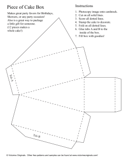

© Copyright 2026