
FIREBIRDS WOOD FIRED GRILL
PROJECT MANUAL
FIREBIRDS WOOD FIRED GRILL
5100 Spotsylvania Towne Center
Fredericksburg, Virginia 22407
Project No. 08-017
OWNER
FIREBIRDS WOOD FIRED GRILL
13900 CONLAN CIRCLE, SUITE 240
CHARLOTTE, NORTH CAROLINA 28227
ARCHITECTS
STUDIO FUSION, PA
725 PROVIDENCE ROAD, SUITE 212
CHARLOTTE, NORTH CAROLINA 28207
PHONE: (704) 377-9799
CONSULTANTS
STRUCTURAL
HUNTER STRUCTURAL, PA
1900 ABBOTT STREET, SUITE 103
CHARLOTTE, NORTH CAROLINA
PHONE: (704) 442-7260
MECHANICAL AND PLUMBING
SABER ENGINEERING
2923 SOUTH TRYON STREET, SUITE 280
CHARLOTTE, NC 28203
PHONE: (704) 373-0068
ELECTRICAL
SABER ENGINEERING
2923 SOUTH TRYON STREET, SUITE 280
CHARLOTTE, NC 28203
PHONE: (704) 373-0068
December 5, 2008
© 2008 Studio Fusion
DOCUMENT 00010 - TABLE OF CONTENTS
PROJECT MANUAL
SERIES 0 - CONTRACT FORMS
00001
Cover Sheet
00010
Table of Contents
DIVISION 1 - GENERAL REQUIREMENTS
01100
Summary
01330
Submittal Procedures
01400
Quality Requirements
01420
References
01500
Temporary Facilities And Controls
01600
Product Requirements
01700
Execution Requirements
01770
Closeout Procedures
DIVISION 2 - SITE CONSTRUCTION
02821
Chain Link Fences and Gates
DIVISION 3 - CONCRETE
03300
Cast-In-Place Concrete
03401
Precast Concrete Countertops
DIVISION 4 - MASONRY
04415
Manufactured Stone Masonry Veneer
DIVISION 5 - METALS
05310
Steel Decking
05400
Cold Formed Metal Framing
05721
Ornamental Railings
DIVISION 6 - WOOD AND PLASTICS
06105
Miscellaneous Carpentry
06160
Sheathing
06202
Interior Finish Carpentry
06401
Exterior Architectural Woodwork
DIVISION 7 - THERMAL AND MOISTURE PROTECTION
07243
Exterior Insulation And Finish Systems – Direct Applied
07543
Thermoplastic-Polyolefin (TPO) Roofing
07920
Joint Sealants
DIVISION 8 - DOORS AND WINDOWS
08110
Steel Doors And Frames
08211
Flush Wood Doors
08380
Traffic Doors
08410
Aluminum Entrances And Storefronts
08710
Door Hardware
08800
Glazing
DIVISION 9 - FINISHES
09260
Gypsum Board Assemblies
Studio Fusion, PA
Project #08-017
1
00010
Firebirds - Fredericksburg, VA
12/5/2008
DOCUMENT 00010 - TABLE OF CONTENTS
09310
09510
09520
09720
09775
09910
09931
Ceramic Tile
Acoustical Panel Ceilings
Specialty Ceilings
Wall Coverings
Sanitary Plastic Paneling
Painting
Wood Stains And Transparent Finishes
DIVISION 10 – SPECIALTIES
10305
Manufactured Fireplaces
10520
Fire Extinguisher Cabinets
10521
Fire Extinguishers
10801
Toilet And Bath Accessories
10900
Miscellaneous Specialties
DIVISION 11 - EQUIPMENT
11451
Residential Appliances
DIVISION 12 - FURNISHINGS
12491
Horizontal Louver Blinds
DIVISION 13 - SPECIAL CONSTRUCTION
NOT APPLICABLE
DIVISION 14 - CONVEYING SYSTEMS
NOT APPLICABLE
DIVISION 15 - MECHANICAL
See Plumbing And Mechanical Drawings
DIVISION 16 - ELECTRICAL
See Electrical Drawings
END OF TABLE OF CONTENTS
Studio Fusion, PA
Project #08-017
2
00010
Firebirds - Fredericksburg, VA
12/5/2008
SECTION 01100 - SUMMARY
PART 1 - GENERAL
1.1
SUMMARY
A. This Section includes the following:
1. Work covered by the Contract Documents.
2. Type of the Contract.
3. Work schedule and sequence.
4. Use of premises.
5. Work restrictions.
6. Specification formats and conventions.
1.2
WORK COVERED BY CONTRACT DOCUMENTS
A. Project Identification: Firebirds Wood Fired Grill, Fredericksburg, Virginia. Project consists of
interior restaurant upfit to an existing building; approximately 6,879 square feet total area, as
indicated on the Drawings and as specified in the Project Manual.
1. Project Location: 5100 Spotsylvania Towne Center, Fredericksburg, Virginia 22407.
2. Owner: Firebirds Wood Fired Grill, 13850 Ballantyne Corporate Place, Suite 450, Charlotte,
North Carolina 28277.
B. Architect Identification: The Contract Documents, originally dated December 6, 2008 for permit
and construction, were prepared for the Project by Studio Fusion, 725 Providence Road, Suite
212, Charlotte, North Carolina 28207.
C. The Work consists of Type IIB construction.
1.3
CONTRACTS
A. Project will be constructed under a general construction contract.
1.4
WORK SCHEDULE AND SEQUENCE
A. The Work shall be conducted in a single phase, with the date of Substantial Completion to be as
indicated in the Agreement.
1.5
USE OF PREMISES
A. General: Contractor shall have full use of premises for construction operations, including use of
Project site, during construction period. Contractor's use of premises is limited only by Owner's
right to perform work or to retain other contractors on portions of Project.
1. Driveways and Entrances: Keep driveways and entrances serving premises clear and
available to Owner, Owner's employees, and emergency vehicles at all times. Do not use
these areas for parking or storage of materials.
a. Schedule deliveries to minimize use of driveways and entrances.
b. Schedule deliveries to minimize space and time requirements for storage of materials and
equipment on-site.
B. Deliveries: Provide representative to receive all materials and offload at the job site. The Owner
will refuse all deliveries to other locations.
C. Personnel Identification: All construction personnel in occupied portions of the facility must wear
Contractor-furnished identification badges at all times. Personnel without proper identification are
subject to removal from the site by the Owner.
D. Safety and Security: Comply with Owner’s requirements related to security and fire drills and alerts.
Studio Fusion, PA
Project #08-017
1
01100
Firebirds - Fredericksburg, VA
12/5/2008
SECTION 01100 - SUMMARY
E. Burning/Welding Operations: Comply with Owner’s requirements related to Burning and Welding
permits. Coordinate turning off of fire/smoke detection systems in affected areas. Contractor shall be
responsible for Fire Department response fees related to construction operations.
F. Smoking: No smoking is allowed on the premises, except within 20 feet of the Contractor’s job
office trailer or as otherwise designated by Owner’s representative.
G. Use of Site: Limit use of premises to indicated areas within the Contract limits. Do not disturb
portions of Project site beyond areas in which the Work is indicated.
1. Limits: Confine constructions operations to areas indicate.
1.6
WORK RESTRICTIONS
A. On-Site Work Hours: Work shall be generally performed during normal business working hours
of 7:00 a.m. to 9:00 p.m., Monday through Friday, except otherwise indicated.
1. Weekend Hours: 8:00 a.m. to 6:00 p.m.
2. Early Morning Hours: Restrict noisy work until after 7:00 a.m.
1.7
SPECIFICATION FORMATS AND CONVENTIONS
A. Specification Format: The Specifications are organized into Divisions and Sections using the 16division format and CSI/CSC's "MasterFormat" numbering system.
B. Specification Content: The Specifications use certain conventions for the style of language and
the intended meaning of certain terms, words, and phrases when used in particular situations.
These conventions are as follows:
1. Abbreviated Language: Language used in the Specifications and other Contract Documents is
abbreviated. Words and meanings shall be interpreted as appropriate. Words implied, but not
stated, shall be inferred, as the sense requires. Singular words shall be interpreted as plural,
and plural words shall be interpreted as singular where applicable as the context of the
Contract Documents indicates.
2. Imperative mood and streamlined language are generally used in the Specifications.
Requirements expressed in the imperative mood are to be performed by Contractor.
Occasionally, the indicative or subjunctive mood may be used in the Section Text for clarity
to describe responsibilities that must be fulfilled indirectly by Contractor or by others when so
noted.
a. The words "shall," "shall be," or "shall comply with," depending on the context, are
implied where a colon (:) is used within a sentence or phrase.
PART 2 - PRODUCTS (Not Used)
PART 3 - EXECUTION (Not Used)
END OF SECTION 01100
Studio Fusion, PA
Project #08-017
2
01100
Firebirds - Fredericksburg, VA
12/5/2008
SECTION 01330 - SUBMITTAL PROCEDURES
PART 1 - GENERAL
1.1
SUMMARY
A. This Section includes administrative and procedural requirements for submitting Shop Drawings,
Product Data, Samples, and other miscellaneous submittals.
1.2
DEFINITIONS
A. Action Submittals: Written and graphic information that requires Architect's responsive action.
B. Informational Submittals: Written information that does not require Architect's approval.
Submittals may be rejected for not complying with requirements.
1.3
SUBMITTAL PROCEDURES
A. Coordination: Coordinate preparation and processing of submittals with performance of
construction activities.
1. Coordinate each submittal with fabrication, purchasing, testing, delivery, other submittals,
and related activities that require sequential activity.
2. Coordinate transmittal of different types of submittals for related parts of the Work so
processing will not be delayed because of need to review submittals concurrently for
coordination.
a. Architect reserves the right to withhold action on a submittal requiring coordination with
other submittals until related submittals are received.
B. Submittals Schedule: Comply with requirements in Division 1 Section "Construction Progress
Documentation" for list of submittals and time requirements for scheduled performance of related
construction activities.
1. Unless otherwise indicated, schedule all submittals to Architect for initial review within 90
days of date of Notice to Proceed.
C. Processing Time: Allow enough time for submittal review, including time for resubmittals, as
follows. Time for review shall commence on Architect's receipt of submittal.
1. Initial Review: Allow 10 business days for initial review of each submittal unless otherwise
indicated. Allow additional time if processing must be delayed to permit coordination with
subsequent submittals. Architect will advise Contractor when a submittal being processed
must be delayed for coordination.
2. If intermediate submittal is necessary, process it in same manner as initial submittal.
3. Allow 10 business days for processing each resubmittal.
4. No extension of the Contract Time will be authorized because of failure to transmit submittals
enough in advance of the Work to permit processing.
5. Concurrent Consultant Review: Where the Contract Documents indicate that submittals may
be transmitted simultaneously to Architect and to Architect's consultants, allow 10 business
days for review of each submittal. Submittal will be returned to Architect before being
returned to Contractor.
D. Identification: Place a permanent label or title block on each submittal for identification.
1. Indicate name of firm or entity that prepared each submittal on label or title block.
2. Provide a space approximately 4 by 5 inches on label or beside title block to record
Contractor's review and approval markings and action taken by Architect.
3. Include the following information on label for processing and recording action taken:
a. Project name.
b. Date.
c. Name and address of Architect.
d. Name and address of Contractor.
Studio Fusion, PA
Project #08-017
1
01330
Firebirds - Fredericksburg, VA
12/5/2008
SECTION 01330 - SUBMITTAL PROCEDURES
e. Name and address of subcontractor.
f. Name and address of supplier.
g. Name of manufacturer.
h. Unique identifier, including revision number.
i. Number and title of appropriate Specification Section.
j. Drawing number and detail references, as appropriate.
k. Other necessary identification.
E. Deviations: Highlight, encircle, or otherwise identify deviations from the Contract Documents on
submittals.
F. Additional Copies: Unless additional copies are required for final submittal, and unless Architect
observes noncompliance with provisions of the Contract Documents, initial submittal may serve
as final submittal.
1. Do not submit additional copies for maintenance manuals.
G. Transmittal: Package each submittal individually and appropriately for transmittal and handling.
Transmit each submittal using a transmittal form. Architect will discard submittals received from
sources other than Contractor.
1. Include Contractor's certification stating that information submitted complies with
requirements of the Contract Documents.
2. Transmittal Form: Use AIA Document G810, CSI Form 12.1A, or other form acceptable to
Architect.
3. On an attached separate sheet, prepared on Contractor's letterhead, record relevant
information, requests for data, revisions other than those requested by Architect on previous
submittals, and deviations from requirements in the Contract Documents, including minor
variations and limitations. Include same label information as related submittal.
H. Resubmittals: Make resubmittals in same form and number of copies as initial submittal.
1. Note date and content of previous submittal.
2. Note date and content of revision in label or title block and clearly indicate extent of revision.
3. Resubmit submittals until they are marked "Approved,” “Approved as noted,” or “No
exceptions taken."
I. Distribution: Furnish copies of final submittals to manufacturers, subcontractors, suppliers,
fabricators, installers, authorities having jurisdiction, and others as necessary for performance of
construction activities. Show distribution on transmittal forms.
J.
Use for Construction: Use only final submittals with mark indicating action taken by Architect in
connection with construction.
PART 2 - PRODUCTS
2.1
ACTION SUBMITTALS
A. General: Prepare and submit Action Submittals required by individual Specification Sections.
1. Number of Copies: Submit five copies of each submittal, unless otherwise indicated. Submit
six copies of submittal for portions of work designed by consulting design professionals.
Architect will return two copies. Mark up and retain one returned copy as a Project Record
Document.
B. Product Data: Collect information into a single submittal for each element of construction and
type of product or equipment.
1. Do not submit product data unless specifically required.
2. If information must be specially prepared for submittal because standard printed data are not
suitable for use, submit as Shop Drawings, not as Product Data.
Studio Fusion, PA
Project #08-017
2
01330
Firebirds - Fredericksburg, VA
12/5/2008
SECTION 01330 - SUBMITTAL PROCEDURES
3. Mark each copy of each submittal to show which products and options are applicable.
4. Include the following information, as applicable:
a. Manufacturer's written recommendations.
b. Manufacturer's product specifications.
c. Manufacturer's installation instructions.
d. Manufacturer's catalog cuts.
e. Wiring diagrams showing factory-installed wiring.
f. Printed performance curves.
g. Operational range diagrams.
h. Compliance with recognized trade association standards.
i. Compliance with recognized testing agency standards.
C. Shop Drawings: Prepare Project-specific information, drawn accurately to scale. Do not base
Shop Drawings on reproductions of the Contract Documents or standard printed data.
1. Preparation: Include the following information, as applicable:
a. Dimensions.
b. Identification of products.
c. Fabrication and installation drawings.
d. Roughing-in and setting diagrams.
e. Wiring diagrams showing field-installed wiring, including power, signal, and control
wiring.
f. Shopwork manufacturing instructions.
g. Templates and patterns.
h. Schedules.
i. Design calculations.
j. Compliance with specified standards.
k. Notation of coordination requirements.
l. Notation of dimensions established by field measurement.
m. Relationship to adjoining construction clearly indicated.
n. Seal and signature of professional engineer if specified.
o. Wiring Diagrams: Differentiate between manufacturer-installed and field-installed wiring.
2. Sheet Size: Except for templates, patterns, and similar full-size drawings, submit Shop
Drawings on sheets at least 8-1/2 by 11 inches but no larger than 30 by 42 inches.
D. Samples: Prepare physical units of materials or products, including the following:
1. Comply with requirements in Division 1 Section "Quality Requirements" for mockups.
2. Samples for Initial Selection: Submit manufacturer's color charts consisting of units or
sections of units showing the full range of colors, textures, and patterns available.
a. Submit three full sets of available choices where color, pattern, texture, or similar
characteristics are required to be selected from manufacturer's product line. Architect will
return submittal with options selected.
3. Samples for Verification: Submit full-size units or Samples of size indicated, prepared from
the same material to be used for the Work, cured and finished in manner specified, and
physically identical with the product proposed for use, and that show full range of color and
texture variations expected. Samples include, but are not limited to, partial sections of
manufactured or fabricated components; small cuts or containers of materials; complete
units of repetitively used materials; swatches showing color, texture, and pattern; color
range sets; and components used for independent testing and inspection.
a. Submit three sets of Samples. Architect will retain one Sample sets; remainder will be
returned.
4. Preparation: Mount, display, or package Samples in manner specified to facilitate review of
qualities indicated. Prepare Samples to match Architect's sample where so indicated. Attach
label on unexposed side.
Studio Fusion, PA
Project #08-017
3
01330
Firebirds - Fredericksburg, VA
12/5/2008
SECTION 01330 - SUBMITTAL PROCEDURES
5. Submit Samples for review of kind, color, pattern, and texture for a final check of these
characteristics with other elements and for a comparison of these characteristics between
final submittal and actual component as delivered and installed. Submit samples requiring
selection at same time.
6. Disposition: Maintain sets of approved Samples at Project site, available for quality-control
comparisons throughout the course of construction activity. Sample sets may be used to
determine final acceptance of construction associated with each set.
E. Product Schedule or List: As required in individual Specification Sections, prepare a written
summary indicating types of products required for the Work and their intended location. Include
the following information in tabular form:
1. Type of product. Include unique identifier for each product.
2. Number and name of room or space.
3. Location within room or space.
4. Number of Copies: Submit five copies of product schedule or list, unless otherwise indicated.
Architect will return two copies.
a. Mark up and retain one returned copy as a Project Record Document.
F. Delegated-Design Submittal: Comply with requirements in Division 1 Section "Quality
Requirements."
G. Subcontract List: Prepare a written summary identifying individuals or firms proposed for each
portion of the Work, including those who are to furnish products or equipment fabricated to a
special design. Use CSI Form 1.5A.
2.2
INFORMATIONAL SUBMITTALS
A. General: Prepare and submit Informational Submittals required by other Specification Sections.
1. Number of Copies: Submit two copies of each submittal, unless otherwise indicated. Architect
will not return copies.
2. Certificates and Certifications: Provide a notarized statement that includes signature of entity
responsible for preparing certification. Certificates and certifications shall be signed by an
officer or other individual authorized to sign documents on behalf of that entity.
3. Test and Inspection Reports: Comply with requirements in Division 1 Section "Quality
Requirements."
B. Contractor's Construction Schedule: Comply with requirements in Division 1 Section "Construction
Progress Documentation."
C. Qualification Data: Prepare written information that demonstrates capabilities and experience of
firm or person. Include lists of completed projects with project names and addresses, names and
addresses of architects and owners, and other information specified.
D. Product Certificates: Prepare written statements on manufacturer's letterhead certifying that
product complies with requirements.
E. Welding Certificates: Prepare written certification that welding procedures and personnel comply
with requirements. Submit record of Welding Procedure Specification (WPS) and Procedure
Qualification Record (PQR) on AWS forms. Include names of firms and personnel certified.
F. Installer Certificates: Prepare written statements on manufacturer's letterhead certifying that
Installer complies with requirements and, where required, is authorized for this specific Project.
G. Manufacturer Certificates: Prepare written statements on manufacturer's letterhead certifying
that manufacturer complies with requirements. Include evidence of manufacturing experience where
required.
H. Material Certificates: Prepare written statements on manufacturer's letterhead certifying that
material complies with requirements.
Studio Fusion, PA
Project #08-017
4
01330
Firebirds - Fredericksburg, VA
12/5/2008
SECTION 01330 - SUBMITTAL PROCEDURES
I.
Material Test Reports: Prepare reports written by a qualified testing agency, on testing agency's
standard form, indicating and interpreting test results of material for compliance with requirements.
J.
Compatibility Test Reports: Prepare reports written by a qualified testing agency, on testing
agency's standard form, indicating and interpreting results of compatibility tests performed
before installation of product. Include written recommendations for primers and substrate
preparation needed for adhesion.
K. Field Test Reports: Prepare reports written by a qualified testing agency, on testing agency's
standard form, indicating and interpreting results of field tests performed either during
installation of product or after product is installed in its final location, for compliance with
requirements.
L. Product Test Reports: Prepare written reports indicating current product produced by
manufacturer complies with requirements. Base reports on evaluation of tests performed by
manufacturer and witnessed by a qualified testing agency, or on comprehensive tests performed
by a qualified testing agency.
M. Research/Evaluation Reports: Prepare written evidence, from a model code organization acceptable to
authorities having jurisdiction, that product complies with building code in effect for Project.
N. Maintenance Data: Prepare written and graphic instructions and procedures for operation and
normal maintenance of products and equipment. Comply with requirements in Division 1 Section
"Closeout Procedures."
O. Design Data: Prepare written and graphic information, including, but not limited to, performance
and design criteria, list of applicable codes and regulations, and calculations. Include list of
assumptions and other performance and design criteria and a summary of loads. Include load
diagrams if applicable. Provide name and version of software, if any, used for calculations.
Include page numbers.
P. Manufacturer's Instructions: Prepare written or published information that documents manufacturer's
recommendations, guidelines, and procedures for installing or operating a product or equipment.
Include name of product and name, address, and telephone number of manufacturer.
Q. Manufacturer's Field Reports: Prepare written information documenting factory-authorized service
representative's tests and inspections.
R. Insurance Certificates and Bonds: Prepare written information indicating current status of
insurance or bonding coverage. Include name of entity covered by insurance or bond, limits of
coverage, amounts of deductibles, if any, and term of the coverage.
2.3
DELEGATED DESIGN
A. Performance and Design Criteria: Where professional design services or certifications by a design
professional are specifically required of Contractor by the Contract Documents, provide products
and systems complying with specific performance and design criteria indicated.
1. If criteria indicated are not sufficient to perform services or certification required, submit a
written request for additional information to Architect.
B. Delegated-Design Submittal: In addition to Shop Drawings, Product Data, and other required
submittals, submit three copies of a statement, signed and sealed by the responsible design
professional, for each product and system specifically assigned to Contractor to be designed or
certified by a design professional.
1. Indicate that products and systems comply with performance and design criteria in the
Contract Documents. Include list of codes, loads, and other factors used in performing these
services.
Studio Fusion, PA
Project #08-017
5
01330
Firebirds - Fredericksburg, VA
12/5/2008
SECTION 01330 - SUBMITTAL PROCEDURES
PART 3 - EXECUTION
3.1
CONTRACTOR'S REVIEW
A. Review each submittal and check for coordination with other Work of the Contract and for
compliance with the Contract Documents. Note corrections and field dimensions. Mark with
approval stamp before submitting to Architect.
B. Approval Stamp: Stamp each submittal with a uniform, approval stamp. Include Project name
and location, submittal number, Specification Section title and number, name of reviewer, date of
Contractor's approval, and statement certifying that submittal has been reviewed, checked, and
approved for compliance with the Contract Documents.
3.2
ARCHITECT'S ACTION
A. General: Architect will not review submittals that do not bear Contractor's approval stamp and
will return them without action.
B. Action Submittals: Architect will review each submittal, make marks to indicate corrections or
modifications required, and return it. Architect will stamp each submittal with an action stamp
and will mark stamp appropriately to indicate action taken.
C. Informational Submittals: Architect will review each submittal and will not return it, or will reject
and return it if it does not comply with requirements. Architect will forward each submittal to
appropriate party.
D. Partial submittals are not acceptable, will be considered nonresponsive, and will be returned
without review.
E. Submittals not required by the Contract Documents will not be reviewed and may be discarded.
END OF SECTION 01330
Studio Fusion, PA
Project #08-017
6
01330
Firebirds - Fredericksburg, VA
12/5/2008
SECTION 01400 - QUALITY REQUIREMENTS
PART 1 - GENERAL
1.1
SUMMARY
A. This Section includes administrative and procedural requirements for quality assurance and
quality control.
B. Testing and inspecting services are required to verify compliance with requirements specified or
indicated. These services do not relieve Contractor of responsibility for compliance with the
Contract Document requirements.
1. Specified tests, inspections, and related actions do not limit Contractor's quality-control
procedures that facilitate compliance with the Contract Document requirements.
2. Requirements for Contractor to provide quality-control services required by Architect, Owner,
or authorities having jurisdiction are not limited by provisions of this Section.
C. See Divisions 2 through 16 Sections for specific test and inspection requirements.
1.2
DEFINITIONS
A. Quality-Assurance Services: Activities, actions, and procedures performed before and during
execution of the Work to guard against defects and deficiencies and substantiate that proposed
construction will comply with requirements.
B. Quality-Control Services: Tests, inspections, procedures, and related actions during and after
execution of the Work to evaluate that actual products incorporated into the Work and completed
construction comply with requirements. Services do not include contract enforcement activities
performed by Architect.
C. Mockups: Full-size, physical assemblies that are constructed on-site. Mockups are used to verify
selections made under sample submittals, to demonstrate aesthetic effects and, where indicated,
qualities of materials and execution, and to review construction, coordination, testing, or
operation; they are not Samples. Approved mockups establish the standard by which the Work
will be judged.
D. Laboratory Mockups: Full-size, physical assemblies that are constructed at testing facility to verify
performance characteristics.
E. Preconstruction Testing: Tests and inspections that are performed specifically for the Project
before products and materials are incorporated into the Work to verify performance or
compliance with specified criteria.
F. Product Testing: Tests and inspections that are performed by an NRTL, an NVLAP, or a testing
agency qualified to conduct product testing and acceptable to authorities having jurisdiction, to
establish product performance and compliance with industry standards.
G. Source Quality-Control Testing: Tests and inspections that are performed at the source, i.e.,
plant, mill, factory, or shop.
H. Field Quality-Control Testing: Tests and inspections that are performed on-site for installation of
the Work and for completed Work.
I.
Testing Agency: An entity engaged to perform specific tests, inspections, or both. Testing
laboratory shall mean the same as testing agency.
J.
Installer/Applicator/Erector: Contractor or another entity engaged by Contractor as an employee,
Subcontractor, or Sub-subcontractor, to perform a particular construction operation, including
installation, erection, application, and similar operations.
1. Using a term such as "carpentry" does not imply that certain construction activities must be
performed by accredited or unionized individuals of a corresponding generic name, such as
Studio Fusion, PA
Project #08-017
1
01400
Firebirds - Fredericksburg, VA
12/5/2008
SECTION 01400 - QUALITY REQUIREMENTS
"carpenter." It also does not imply that requirements specified apply exclusively to
tradespeople of the corresponding generic name.
K. Experienced: When used with an entity, "experienced" means having successfully completed a
minimum of five previous projects similar in size and scope to this Project; being familiar with
special requirements indicated; and having complied with requirements of authorities having
jurisdiction.
1.3
CONFLICTING REQUIREMENTS
A. General: If compliance with two or more standards is specified and the standards establish
different or conflicting requirements for minimum quantities or quality levels, comply with the
most stringent requirement. Refer uncertainties and requirements that are different, but
apparently equal, to Architect for a decision before proceeding.
B. Minimum Quantity or Quality Levels: The quantity or quality level shown or specified shall be the
minimum provided or performed. The actual installation may comply exactly with the minimum
quantity or quality specified, or it may exceed the minimum within reasonable limits. To comply
with these requirements, indicated numeric values are minimum or maximum, as appropriate, for
the context of requirements. Refer uncertainties to Architect for a decision before proceeding.
1.4
SUBMITTALS
A. Qualification Data: For testing agencies specified in "Quality Assurance" Article to demonstrate
their capabilities and experience. Include proof of qualifications in the form of a recent report on
the inspection of the testing agency by a recognized authority.
B. Schedule of Tests and Inspections: Prepare in tabular form and include the following:
1. Specification Section number and title.
2. Description of test and inspection.
3. Identification of applicable standards.
4. Identification of test and inspection methods.
5. Number of tests and inspections required.
6. Time schedule or time span for tests and inspections.
7. Entity responsible for performing tests and inspections.
8. Requirements for obtaining samples.
9. Unique characteristics of each quality-control service.
C. Reports: Prepare and submit certified written reports that include the following:
1. Date of issue.
2. Project title and number.
3. Name, address, and telephone number of testing agency.
4. Dates and locations of samples and tests or inspections.
5. Names of individuals making tests and inspections.
6. Description of the Work and test and inspection method.
7. Identification of product and Specification Section.
8. Complete test or inspection data.
9. Test and inspection results and an interpretation of test results.
10. Ambient conditions at time of sample taking and testing and inspecting.
11. Comments or professional opinion on whether tested or inspected Work complies with the
Contract Document requirements.
12. Name and signature of laboratory inspector.
13. Recommendations on retesting and reinspecting.
D. Permits, Licenses, and Certificates: For Owner's records, submit copies of permits, licenses,
certifications, inspection reports, releases, jurisdictional settlements, notices, receipts for fee
Studio Fusion, PA
Project #08-017
2
01400
Firebirds - Fredericksburg, VA
12/5/2008
SECTION 01400 - QUALITY REQUIREMENTS
payments, judgments, correspondence, records, and similar documents, established for
compliance with standards and regulations bearing on performance of the Work.
1.5
QUALITY ASSURANCE
A. General: Qualifications paragraphs in this Article establish the minimum qualification levels
required; individual Specification Sections specify additional requirements.
B. Installer Qualifications: A firm or individual experienced in installing, erecting, or assembling work
similar in material, design, and extent to that indicated for this Project, whose work has resulted
in construction with a record of successful in-service performance.
C. Manufacturer Qualifications: A firm experienced in manufacturing products or systems similar to
those indicated for this Project and with a record of successful in-service performance, as well as
sufficient production capacity to produce required units.
D. Fabricator Qualifications: A firm experienced in producing products similar to those indicated for
this Project and with a record of successful in-service performance, as well as sufficient
production capacity to produce required units.
E. Professional Engineer Qualifications: A professional engineer who is legally qualified to practice in
jurisdiction where Project is located and who is experienced in providing engineering services of
the kind indicated. Engineering services are defined as those performed for installations of the
system, assembly, or product that are similar to those indicated for this Project in material,
design, and extent.
F. Testing Agency Qualifications: An NRTL, an NVLAP, or an independent agency with the
experience and capability to conduct testing and inspecting indicated, as documented according
to ASTM E 548; and with additional qualifications specified in individual Sections; and where
required by authorities having jurisdiction, that is acceptable to authorities.
1. NRTL: A nationally recognized testing laboratory according to 29 CFR 1910.7.
2. NVLAP: A testing agency accredited according to NIST's National Voluntary Laboratory
Accreditation Program.
G. Factory-Authorized Service Representative Qualifications: An authorized representative of
manufacturer who is trained and approved by manufacturer to inspect installation of
manufacturer's products that are similar in material, design, and extent to those indicated for this
Project.
H. Preconstruction Testing: Where testing agency is indicated to perform preconstruction testing for
compliance with specified requirements for performance and test methods, comply with the
following:
1. Contractor responsibilities include the following:
a. Provide test specimens representative of proposed products and construction.
b. Submit specimens in a timely manner with sufficient time for testing and analyzing
results to prevent delaying the Work.
c. Provide sizes and configurations of test assemblies, mockups, and laboratory mockups to
adequately demonstrate capability of products to comply with performance requirements.
d. Build site-assembled test assemblies and mockups using installers who will perform same
tasks for Project.
e. Build laboratory mockups at testing facility using personnel, products, and methods of
construction indicated for the completed Work.
f. When testing is complete, remove test specimens, assemblies, mockups, and laboratory
mockups; do not reuse products on Project.
2. Testing Agency Responsibilities: Submit a certified written report of each test, inspection, and
similar quality-assurance service to Architect, with copy to Contractor. Interpret tests and
inspections and state in each report whether tested and inspected work complies with or
deviates from the Contract Documents.
Studio Fusion, PA
Project #08-017
3
01400
Firebirds - Fredericksburg, VA
12/5/2008
SECTION 01400 - QUALITY REQUIREMENTS
I.
1.6
Mockups: Before installing portions of the Work requiring mockups, build mockups for each form
of construction and finish required to comply with the following requirements, using materials
indicated for the completed Work:
1. Build mockups in location and of size indicated or, if not indicated, as directed by Architect.
2. Notify Architect seven days in advance of dates and times when mockups will be constructed.
3. Demonstrate the proposed range of aesthetic effects and workmanship.
4. Obtain Architect's approval of mockups before starting work, fabrication, or construction.
5. Maintain mockups during construction in an undisturbed condition as a standard for judging
the completed Work.
6. Demolish and remove mockups when directed, unless otherwise indicated.
QUALITY CONTROL
A. Owner Responsibilities: Where quality-control services are indicated as Owner's responsibility,
Owner will engage a qualified testing agency to perform these services.
1. Owner will furnish Contractor with names, addresses, and telephone numbers of testing
agencies engaged and a description of the types of testing and inspecting they are engaged
to perform.
2. Costs for retesting and reinspecting construction that replaces or is necessitated by work that
failed to comply with the Contract Documents will be charged to Contractor, and the Contract
Sum will be adjusted by Change Order.
B. Tests and inspections not explicitly assigned to Owner are Contractor's responsibility. Unless
otherwise indicated, provide quality-control services specified and those required by authorities
having jurisdiction. Perform quality-control services required of Contractor by authorities having
jurisdiction, whether specified or not.
1. Where services are indicated as Contractor's responsibility, engage a qualified testing agency
to perform these quality-control services.
a. Contractor shall not employ same entity engaged by Owner, unless agreed to in writing
by Owner.
2. Notify testing agencies at least 24 hours in advance of time when Work that requires testing
or inspecting will be performed.
3. Where quality-control services are indicated as Contractor's responsibility, submit a certified
written report, in duplicate, of each quality-control service.
4. Testing and inspecting requested by Contractor and not required by the Contract Documents
are Contractor's responsibility.
5. Submit additional copies of each written report directly to authorities having jurisdiction,
when they so direct.
C. Manufacturer's Field Services: Where indicated, engage a factory-authorized service
representative to inspect field-assembled components and equipment installation, including
service connections. Report results in writing.
D. Retesting/Reinspecting: Regardless of whether original tests or inspections were Contractor's
responsibility, provide quality-control services, including retesting and reinspecting, for
construction that revised or replaced Work that failed to comply with requirements established by
the Contract Documents.
E. Testing Agency Responsibilities: Cooperate with Architect and Contractor in performance of
duties. Provide qualified personnel to perform required tests and inspections.
1. Notify Architect and Contractor promptly of irregularities or deficiencies observed in the Work
during performance of its services.
2. Interpret tests and inspections and state in each report whether tested and inspected work
complies with or deviates from requirements.
Studio Fusion, PA
Project #08-017
4
01400
Firebirds - Fredericksburg, VA
12/5/2008
SECTION 01400 - QUALITY REQUIREMENTS
3. Submit a certified written report, in duplicate, of each test, inspection, and similar qualitycontrol service through Contractor.
4. Do not release, revoke, alter, or increase requirements of the Contract Documents or
approve or accept any portion of the Work.
5. Do not perform any duties of Contractor.
F. Associated Services: Cooperate with agencies performing required tests, inspections, and similar
quality-control services, and provide reasonable auxiliary services as requested. Notify agency
sufficiently in advance of operations to permit assignment of personnel. Provide the following:
1. Access to the Work.
2. Incidental labor and facilities necessary to facilitate tests and inspections.
3. Adequate quantities of representative samples of materials that require testing and
inspecting. Assist agency in obtaining samples.
4. Facilities for storage and field-curing of test samples.
5. Delivery of samples to testing agencies.
6. Preliminary design mix proposed for use for material mixes that require control by testing
agency.
7. Security and protection for samples and for testing and inspecting equipment at Project site.
G. Coordination: Coordinate sequence of activities to accommodate required quality-assurance and
quality-control services with a minimum of delay and to avoid necessity of removing and
replacing construction to accommodate testing and inspecting.
1. Schedule times for tests, inspections, obtaining samples, and similar activities.
2. Do not install finishes until required inspection of concealed construction is completed and
work approved.
a. Coordinate in-wall and above-ceiling inspection by authorities having jurisdiction and
observation by Architect.
H. Schedule of Tests and Inspections: Prepare a schedule of tests, inspections, and similar qualitycontrol services required by the Contract Documents. Submit schedule within 30 days of date
established for the Notice to Proceed.
1. Distribution: Distribute schedule to Owner, Architect, testing agencies, and each party
involved in performance of portions of the Work where tests and inspections are required.
I. Special Tests and Inspections: Owner will engage a qualified testing agency or special inspector
to conduct special tests and inspections required by authorities having jurisdiction as the
responsibility of Owner, and as follows:
1. Verifying that manufacturer maintains detailed fabrication and quality-control procedures and
reviewing the completeness and adequacy of those procedures to perform the Work.
2. Notifying Architect and Contractor promptly of irregularities and deficiencies observed in the
Work during performance of its services.
3. Submitting a certified written report of each test, inspection, and similar quality-control
service to Architect with copy to Contractor and to authorities having jurisdiction.
4. Submitting a final report of special tests and inspections at Substantial Completion, which
includes a list of unresolved deficiencies.
5. Interpreting tests and inspections and stating in each report whether tested and inspected
work complies with or deviates from the Contract Documents.
6. Retesting and reinspecting corrected work.
Studio Fusion, PA
Project #08-017
5
01400
Firebirds - Fredericksburg, VA
12/5/2008
SECTION 01400 - QUALITY REQUIREMENTS
PART 2 - PRODUCTS (Not Used)
PART 3 - EXECUTION
3.1
TEST AND INSPECTION LOG
A. Prepare a record of tests and inspections. Include the following:
1. Date test or inspection was conducted.
2. Description of the Work tested or inspected.
3. Date test or inspection results were transmitted to Architect.
4. Identification of testing agency or special inspector conducting test or inspection.
B. Maintain log at Project site. Post changes and modifications as they occur. Provide access to test
and inspection log for Architect's reference during normal working hours.
3.2
REPAIR AND PROTECTION
A. General: On completion of testing, inspecting, sample taking, and similar services, repair
damaged construction and restore substrates and finishes.
1. Comply with the Contract Document requirements for Division 1 Section "Cutting and
Patching."
B. Protect construction exposed by or for quality-control service activities.
C. Repair and protection are Contractor's responsibility, regardless of the assignment of
responsibility for quality-control services.
END OF SECTION 01400
Studio Fusion, PA
Project #08-017
6
01400
Firebirds - Fredericksburg, VA
12/5/2008
SECTION 01420 - REFERENCES
PART 1 - GENERAL
1.1
DEFINITIONS
A. General: Basic Contract definitions are included in the Conditions of the Contract.
B. "Approved": When used to convey Architect's action on Contractor's submittals, applications, and
requests, "approved" is limited to Architect's duties and responsibilities as stated in the
Conditions of the Contract.
C. "Directed": A command or instruction by Architect. Other terms including "requested,"
"authorized," "selected," "approved," "required," and "permitted" have the same meaning as
"directed."
D. "Indicated": Requirements expressed by graphic representations or in written form on Drawings,
in Specifications, and in other Contract Documents. Other terms including "shown," "noted,"
"scheduled," and "specified" have the same meaning as "indicated."
E. "Regulations": Laws, ordinances, statutes, and lawful orders issued by authorities having
jurisdiction, and rules, conventions, and agreements within the construction industry that control
performance of the Work.
F. "Furnish": Supply and deliver to Project site, ready for unloading, unpacking, assembly,
installation, and similar operations.
G. "Install": Operations at Project site including unloading, temporarily storing, unpacking,
assembling, erecting, placing, anchoring, applying, working to dimension, finishing, curing,
protecting, cleaning, and similar operations.
H. "Provide": Furnish and install, complete and ready for the intended use.
I.
J.
"Installer": Contractor or another entity engaged by Contractor as an employee, Subcontractor,
or Sub-subcontractor, to perform a particular construction operation, including installation,
erection, application, and similar operations.
1. Using a term such as "carpentry" does not imply that certain construction activities must be
performed by accredited or unionized individuals of a corresponding generic name, such as
"carpenter." It also does not imply that requirements specified apply exclusively to
tradespeople of the corresponding generic name.
"Experienced": When used with an entity, "experienced" means having successfully completed a
minimum of five previous projects similar in size and scope to this Project; being familiar with
special requirements indicated; and having complied with requirements of authorities having
jurisdiction.
K. "Project Site": Space available for performing construction activities. The extent of Project site is
shown on Drawings and may or may not be identical with the description of the land on which
Project is to be built.
1.2
INDUSTRY STANDARDS
A. Applicability of Standards: Unless the Contract Documents include more stringent requirements,
applicable construction industry standards have the same force and effect as if bound or copied
directly into the Contract Documents to the extent referenced. Such standards are made a part of
the Contract Documents by reference.
B. Publication Dates: Comply with standards in effect as of date of the Contract Documents, unless
otherwise indicated.
C. Conflicting Requirements: If compliance with two or more standards is specified and the
standards establish different or conflicting requirements for minimum quantities or quality levels,
Studio Fusion, PA
Project #08-017
1
01420
Firebirds - Fredericksburg, VA
12/5/2008
SECTION 01420 - REFERENCES
comply with the most stringent requirement. Refer uncertainties and requirements that are
different, but apparently equal, to Architect for a decision before proceeding.
1. Minimum Quantity or Quality Levels: The quantity or quality level shown or specified shall be
the minimum provided or performed. The actual installation may comply exactly with the
minimum quantity or quality specified, or it may exceed the minimum within reasonable
limits. To comply with these requirements, indicated numeric values are minimum or
maximum, as appropriate, for the context of requirements. Refer uncertainties to Architect
for a decision before proceeding.
D. Copies of Standards: Each entity engaged in construction on Project must be familiar with
industry standards applicable to its construction activity. Copies of applicable standards are not
bound with the Contract Documents.
1. Where copies of standards are needed to perform a required construction activity, obtain
copies directly from publication source and make them available on request.
E. Abbreviations and Acronyms for Standards and Regulations: Where abbreviations and acronyms
are used in Specifications or other Contract Documents, they shall mean the recognized name of
the standards and regulations in the following list.
1.3
ADAAG
Americans with Disabilities Act (ADA)
CFR
Code of Federal Regulations
CRD
Handbook for Concrete and Cement
DOD
Department of Defense Specifications and Standards
FED-STD
Federal Standard (See FS)
FS
Federal Specification
FTMS
Federal Test Method Standard (See FS)
MILSPEC
Military Specification and Standards
UFAS
Uniform Federal Accessibility Standards
ABBREVIATIONS AND ACRONYMS
A. Industry Organizations: Where abbreviations and acronyms are used in Specifications or other
Contract Documents, they shall mean the recognized name of the entities indicated in Gale
Research's "Encyclopedia of Associations" or in Columbia Books' "National Trade & Professional
Associations of the U.S."
B. Code Agencies: Where abbreviations and acronyms are used in Specifications or other Contract
Documents, they shall mean the recognized name of the entities in the following list.
BOCA
BOCA International, Inc.
CABO
Council of American Building Officials (See ICC)
IAPMO
International Association of Plumbing and Mechanical Officials (The)
Studio Fusion, PA
Project #08-017
2
01420
Firebirds - Fredericksburg, VA
12/5/2008
SECTION 01420 - REFERENCES
ICBO
International Conference of Building Officials
ICC
International Code Council, Inc.
(Formerly: CABO - Council of American Building Officials)
SBCCI
Southern Building Code Congress International, Inc.
C. Federal Government Agencies: Where abbreviations and acronyms are used in Specifications or
other Contract Documents, they shall mean the recognized name of the entities in the following
list.
ACE
Army Corps of Engineers
CPSC
Consumer Product Safety Commission
DOC
Department of Commerce
EPA
Environmental Protection Agency
FAA
Federal Aviation Administration
FDA
Food and Drug Administration
GSA
General Services Administration
HUD
Department of Housing and Urban Development
LBL
Lawrence Berkeley Laboratory (See LBNL)
LBNL
Lawrence Berkeley National Laboratory
NCHRP
National Cooperative Highway Research Program (See TRB)
NIST
National Institute of Standards and Technology
OSHA
Occupational Safety & Health Administration
PBS
Public Building Service (See GSA)
RUS
Rural Utilities Service (See USDA)
TRB
Transportation Research Board
USDA
Department of Agriculture
USPS
Postal Service
Studio Fusion, PA
Project #08-017
3
01420
Firebirds - Fredericksburg, VA
12/5/2008
SECTION 01420 - REFERENCES
PART 2 - PRODUCTS (Not Used)
PART 3 - EXECUTION (Not Used)
END OF SECTION 01420
Studio Fusion, PA
Project #08-017
4
01420
Firebirds - Fredericksburg, VA
12/5/2008
SECTION 01500 - TEMPORARY FACILITIES AND CONTROLS
PART 1 - GENERAL
1.1
SUMMARY
A. This Section includes requirements for temporary facilities and controls, including temporary
utilities, support facilities, and security and protection facilities.
B. Temporary utilities include, but are not limited to, the following:
1. Sanitary facilities, including toilets, wash facilities, and drinking-water facilities.
2. Heating and cooling facilities.
3. Ventilation.
4. Electric power service.
5. Lighting.
6. Telephone service.
C. Support facilities include, but are not limited to, the following:
1. Project identification and temporary signs.
2. Waste disposal facilities.
3. Field offices.
4. Construction aids and miscellaneous services and facilities.
D. Security and protection facilities include, but are not limited to, the following:
1. Temporary enclosures.
2. Temporary partitions.
3. Fire protection.
1.2
USE CHARGES
A. General: Cost or use charges for temporary facilities are not chargeable to Owner or Architect
and shall be included in the Contract Sum. Allow other entities to use temporary services and
facilities without cost, including, but not limited to, the following:
1. Owner's construction forces.
2. Occupants of Project.
3. Architect.
4. Testing agencies.
5. Personnel of authorities having jurisdiction.
1.3
QUALITY ASSURANCE
A. Standards: Comply with ANSI A10.6, NECA's "Temporary Electrical Facilities," and NFPA 241.
1. Trade Jurisdictions: Assigned responsibilities for installation and operation of temporary
utilities are not intended to interfere with trade regulations and union jurisdictions.
2. Electric Service: Comply with NECA, NEMA, and UL standards and regulations for temporary
electric service. Install service to comply with NFPA 70.
1.4
PROJECT CONDITIONS
A. Conditions of Use: The following conditions apply to use of temporary services and facilities by all
parties engaged in the Work:
1. Keep temporary services and facilities clean and neat.
2. Relocate temporary services and facilities as required by progress of the Work.
B. Temporary Use of Permanent Facilities: Installer of each permanent service shall assume
responsibility for operation, maintenance, and protection of each permanent service during its
use as a construction facility before Owner's acceptance, regardless of previously assigned
responsibilities.
Studio Fusion, PA
Project #08-017
1
01500
Firebirds - Fredericksburg, VA
12/5/2008
SECTION 01500 - TEMPORARY FACILITIES AND CONTROLS
PART 2 - PRODUCTS
2.1
MATERIALS
A. General: Provide new materials. Undamaged, previously used materials in serviceable condition
may be used if approved by Architect. Provide materials suitable for use intended.
B. Chain-Link Fencing: Minimum 2-inch 9-gage, galvanized steel, chain-link fabric fencing; minimum
6 feet high with galvanized steel pipe posts; minimum 2-3/8-inch- OD line posts and 2-7/8-inchOD corner and pull posts, with 1-5/8-inch- OD top and bottom rails. Provide galvanized steel
bases for supporting posts.
C. Gypsum Board: Minimum 1/2 inch thick by 48 inches wide by maximum available lengths;
regular-type panels with tapered edges. Comply with ASTM C 36.
D. Insulation: Unfaced mineral-fiber blanket, manufactured from glass, slag wool, or rock wool; with
maximum flame-spread and smoke-developed indices of 25 and 50, respectively.
E. Paint: Comply with requirements in Division 9 Section "Painting."
F. Tarpaulins: Fire-resistive labeled with flame-spread rating of 15 or less.
G. Water: Potable.
2.2
EQUIPMENT
A. General: Provide equipment suitable for use intended.
B. Field Offices: Mobile units with lockable entrances, operable windows, and serviceable finishes;
heated and air conditioned; on foundations adequate for normal loading.
C. Fire Extinguishers: Hand carried, portable, UL rated. Provide class and extinguishing agent as
indicated or a combination of extinguishers of NFPA-recommended classes for exposures.
1. Comply with NFPA 10 and NFPA 241 for classification, extinguishing agent, and size required
by location and class of fire exposure.
D. Self-Contained Toilet Units: Single-occupant units of chemical, aerated recirculation, or
combustion type; vented; fully enclosed with a glass-fiber-reinforced polyester shell or similar
nonabsorbent material.
E. Drinking-Water Fixtures: Containerized, tap-dispenser, bottled-water drinking-water units,
including paper cup supply.
F. Electrical Outlets: Properly configured, NEMA-polarized outlets to prevent insertion of 110- to
120-V plugs into higher-voltage outlets; equipped with ground-fault circuit interrupters, reset
button, and pilot light.
G. Power Distribution System Circuits: Where permitted and overhead and exposed for surveillance,
wiring circuits, not exceeding 125-V ac, 20-A rating, and lighting circuits may be nonmetallic
sheathed cable.
PART 3 - EXECUTION
3.1
INSTALLATION, GENERAL
A. Locate facilities where they will serve Project adequately and result in minimum interference with
performance of the Work. Relocate and modify facilities as required.
B. Provide each facility ready for use when needed to avoid delay. Maintain and modify as required.
Do not remove until facilities are no longer needed or are replaced by authorized use of
completed permanent facilities.
Studio Fusion, PA
Project #08-017
2
01500
Firebirds - Fredericksburg, VA
12/5/2008
SECTION 01500 - TEMPORARY FACILITIES AND CONTROLS
3.2
TEMPORARY UTILITY INSTALLATION
A. Water Service: Use of Owner's existing water service facilities will be permitted, as long as
facilities are cleaned and maintained in a condition acceptable to Owner. At Substantial
Completion, restore these facilities to condition existing before initial use.
1. Provide rubber hoses as necessary to serve Project site.
B. Sanitary Facilities: Provide temporary toilets, wash facilities, and drinking-water fixtures. Comply
with regulations and health codes for type, number, location, operation, and maintenance of
fixtures and facilities.
1. Disposable Supplies: Provide toilet tissue, paper towels, paper cups, and similar disposable
materials for each facility. Maintain adequate supply. Provide covered waste containers for
disposal of used material.
2. Toilets: Install self-contained toilet units. Shield toilets to ensure privacy.
3. Drinking-Water Facilities: Provide bottled-water, drinking-water units.
C. Ventilation and Humidity Control: Provide temporary ventilation required by construction activities
for curing or drying of completed installations or for protecting installed construction from
adverse effects of high humidity. Select equipment from that specified that will not have a
harmful effect on completed installations or elements being installed. Coordinate ventilation
requirements to produce ambient condition required and minimize energy consumption.
D. Electric Distribution: Provide receptacle outlets adequate for connection of power tools and
equipment.
1. Provide waterproof connectors to connect separate lengths of electrical power cords if single
lengths will not reach areas where construction activities are in progress. Do not exceed safe
length-voltage ratio.
E. Lighting: Provide temporary lighting with local switching that provides adequate illumination for
construction operations and traffic conditions.
1. Install and operate temporary lighting that fulfills security and protection requirements
without operating entire system.
F. Telephone Service: Provide temporary telephone service throughout construction period for
common-use facilities used by all personnel engaged in construction activities. Install separate
telephone line for each field office and first-aid station.
1. At each telephone, post a list of important telephone numbers.
2. Provide voice-mail service on superintendent's telephone.
3. Provide a portable cellular telephone for superintendent's use in making and receiving
telephone calls when away from field office.
3.3
SUPPORT FACILITIES INSTALLATION
A. General: Comply with the following:
1. Provide incombustible construction for offices, shops, and sheds located within construction
area or within 30 feet of building lines. Comply with NFPA 241.
2. Maintain support facilities until near Substantial Completion. Remove before Substantial
Completion. Personnel remaining after Substantial Completion will be permitted to use
permanent facilities, under conditions acceptable to Owner.
B. Project Identification and Temporary Signs: Prepare Project identification and other signs in sizes
indicated. Install signs where indicated to inform public and persons seeking entrance to Project.
Do not permit installation of unauthorized signs.
1. Engage an experienced sign painter to apply graphics for Project identification signs. Comply
with details indicated.
2. Prepare temporary signs to provide directional information to construction personnel and
visitors.
Studio Fusion, PA
Project #08-017
3
01500
Firebirds - Fredericksburg, VA
12/5/2008
SECTION 01500 - TEMPORARY FACILITIES AND CONTROLS
3. Construct signs of exterior-type Grade B-B high-density concrete form overlay plywood in
sizes and thicknesses indicated. Support on posts or framing of preservative-treated wood or
steel.
4. Paint sign panel and applied graphics with exterior-grade alkyd gloss enamel over exterior
primer.
C. Waste Disposal Facilities: Provide waste-collection containers in sizes adequate to handle waste
from construction operations. Containerize and clearly label hazardous, dangerous, or unsanitary
waste materials separately from other waste. Comply with Division 1 Section "Execution
Requirements" for progress cleaning requirements.
1. If required by authorities having jurisdiction, provide separate containers, clearly labeled, for
each type of waste material to be deposited.
2. Develop a waste management plan for Work performed on Project. Indicate types of waste
materials Project will produce and estimate quantities of each type. Provide detailed
information for on-site waste storage and separation of recyclable materials. Provide
information on destination of each type of waste material and means to be used to dispose
of all waste materials.
D. Janitorial Services: Provide janitorial services on a daily basis for temporary offices, first-aid
stations, toilets, wash facilities, lunchrooms, and similar areas.
3.4
SECURITY AND PROTECTION FACILITIES INSTALLATION
A. Environmental Protection: Provide protection, operate temporary facilities, and conduct
construction in ways and by methods that comply with environmental regulations and that
minimize possible air, waterway, and subsoil contamination or pollution or other undesirable
effects. Avoid using tools and equipment that produce harmful noise. Restrict use of noisemaking
tools and equipment to hours that will minimize complaints from persons or firms near Project
site.
B. Pest Control: Before deep foundation work has been completed, retain a local exterminator or
pest-control company to recommend practices to minimize attraction and harboring of rodents,
roaches, and other pests. Engage this pest-control service to perform extermination and control
procedures at regular intervals so Project will be free of pests and their residues at Substantial
Completion. Obtain extended warranty for Owner. Perform control operations lawfully, using
environmentally safe materials.
C. Temporary Enclosures: Provide temporary enclosures for protection of construction, in progress
and completed, from exposure, foul weather, other construction operations, and similar activities.
Provide temporary weathertight enclosure for building exterior.
1. Where heating or cooling is needed and permanent enclosure is not complete, provide
insulated temporary enclosures. Coordinate enclosure with ventilating and material drying or
curing requirements to avoid dangerous conditions and effects.
2. Vertical Openings: Close openings of 25 sq. ft. or less with plywood or similar materials.
3. Horizontal Openings: Close openings in floor or roof decks and horizontal surfaces with loadbearing, wood-framed construction.
4. Install tarpaulins securely using fire-retardant-treated wood framing and other materials.
5. Where temporary wood or plywood enclosure exceeds 100 sq. ft. in area, use fire-retardanttreated material for framing and main sheathing.
D. Temporary Partitions: Erect and maintain dustproof partitions and temporary enclosures to limit
dust and dirt migration and to separate areas from fumes and noise.
1. Construct dustproof partitions of not less than nominal 4-inch studs, 5/8-inch gypsum
wallboard with joints taped on occupied side, and 1/2-inch fire-retardant plywood on
construction side.
Studio Fusion, PA
Project #08-017
4
01500
Firebirds - Fredericksburg, VA
12/5/2008
SECTION 01500 - TEMPORARY FACILITIES AND CONTROLS
2. Comply with requirements of authorities having jurisdiction for temporary partitions with fireseparation assembly requirements.
3. Insulate partitions to provide noise protection to occupied areas.
4. Seal joints and perimeter. Equip partitions with dustproof doors and security locks.
5. Protect air-handling equipment.
6. Weatherstrip openings.
E. Temporary Fire Protection: Until fire-protection needs are supplied by permanent facilities, install
and maintain temporary fire-protection facilities of types needed to protect against reasonably
predictable and controllable fire losses. Comply with NFPA 241.
1. Provide fire extinguishers, installed on walls on mounting brackets, visible and accessible
from space being served, with sign mounted above.
a. Field Offices: Class A stored-pressure water-type extinguishers.
b. Other Locations: Class ABC dry-chemical extinguishers or a combination of extinguishers
of NFPA-recommended classes for exposures.
c. Locate fire extinguishers where convenient and effective for their intended purpose;
provide not less than one extinguisher on each floor at or near each usable stairwell.
2. Store combustible materials in containers in fire-safe locations.
3. Maintain unobstructed access to fire extinguishers, fire hydrants, temporary fire-protection
facilities, stairways, and other access routes for firefighting. Prohibit smoking in hazardous
fire-exposure areas.
4. Supervise welding operations, combustion-type temporary heating units, and similar sources
of fire ignition.
5. Permanent Fire Protection: At earliest feasible date in each area of Project, complete
installation of permanent fire-protection facility, including connected services, and place into
operation and use. Instruct key personnel on use of facilities.
6. Develop and supervise an overall fire-prevention and first-aid fire-protection program for
personnel at Project site. Review needs with local fire department and establish procedures
to be followed. Instruct personnel in methods and procedures. Post warnings and
information.
7. Provide hoses for fire protection of sufficient length to reach construction areas. Hang hoses
with a warning sign stating that hoses are for fire-protection purposes only and are not to be
removed. Match hose size with outlet size and equip with suitable nozzles.
3.5
OPERATION, TERMINATION, AND REMOVAL
A. Supervision: Enforce strict discipline in use of temporary facilities. To minimize waste and abuse,
limit availability of temporary facilities to essential and intended uses.
B. Maintenance: Maintain facilities in good operating condition until removal. Protect from damage
caused by freezing temperatures and similar elements.
1. Maintain operation of temporary enclosures, heating, cooling, humidity control, ventilation,
and similar facilities on a 24-hour basis where required to achieve indicated results and to
avoid possibility of damage.
2. Prevent water-filled piping from freezing. Maintain markers for underground lines. Protect
from damage during excavation operations.
C. Temporary Facility Changeover: Except for using permanent fire protection as soon as available,
do not change over from using temporary security and protection facilities to permanent facilities
until Substantial Completion.
D. Termination and Removal: Remove each temporary facility when need for its service has ended,
when it has been replaced by authorized use of a permanent facility, or no later than Substantial
Completion. Complete or, if necessary, restore permanent construction that may have been
delayed because of interference with temporary facility. Repair damaged Work, clean exposed
surfaces, and replace construction that cannot be satisfactorily repaired.
Studio Fusion, PA
Project #08-017
5
01500
Firebirds - Fredericksburg, VA
12/5/2008
SECTION 01500 - TEMPORARY FACILITIES AND CONTROLS
1. Materials and facilities that constitute temporary facilities are the property of Contractor.
Owner reserves right to take possession of Project identification signs.
2. At Substantial Completion, clean and renovate permanent facilities used during construction
period. Comply with final cleaning requirements in Division 1 Section "Closeout Procedures."
END OF SECTION 01500
Studio Fusion, PA
Project #08-017
6
01500
Firebirds - Fredericksburg, VA
12/5/2008
SECTION 01600 - PRODUCT REQUIREMENTS
PART 1 - GENERAL
1.1
SUMMARY
A. This Section includes administrative and procedural requirements for selection of products for use
in Project; product delivery, storage, and handling; manufacturers' standard warranties on
products; special warranties; product substitutions; and comparable products.
B. Related Sections include the following:
1. Divisions 2 through 16 Sections for specific requirements for warranties on products and
installations specified to be warranted.
1.2
DEFINITIONS
A. Products: Items purchased for incorporating into the Work, whether purchased for Project or
taken from previously purchased stock. The term "product" includes the terms "material,"
"equipment," "system," and terms of similar intent.
1. Named Products: Items identified by manufacturer's product name, including make or model
number or other designation shown or listed in manufacturer's published product literature,
that is current as of date of the Contract Documents.
2. New Products: Items that have not previously been incorporated into another project or
facility, except that products consisting of recycled-content materials are allowed, unless
explicitly stated otherwise. Products salvaged or recycled from other projects are not
considered new products.
3. Comparable Product: Product that is demonstrated and approved through submittal process,
or where indicated as a product substitution, to have the indicated qualities related to type,
function, dimension, in-service performance, physical properties, appearance, and other
characteristics that equal or exceed those of specified product.
B. Substitutions: Changes in products, materials, equipment, and methods of construction from
those required by the Contract Documents and proposed by Contractor.
C. Basis-of-Design Product Specification: Where a specific manufacturer's product is named and
accompanied by the words "basis of design," including make or model number or other
designation, to establish the significant qualities related to type, function, dimension, in-service
performance, physical properties, appearance, and other characteristics for purposes of
evaluating comparable products of other named manufacturers.
1.3
SUBMITTALS
A. Product List: Submit a list, in tabular from, showing specified products. Include generic names of
products required. Include manufacturer's name and proprietary product names for each product.
1. Coordinate product list with Contractor's Construction Schedule and the Submittals Schedule.
2. Form: Tabulate information for each product under the following column headings:
a. Specification Section number and title.
b. Generic name used in the Contract Documents.
c. Proprietary name, model number, and similar designations.
d. Manufacturer's name and address.
e. Supplier's name and address.
f. Installer's name and address.
g. Projected delivery date or time span of delivery period.
h. Identification of items that require early submittal approval for scheduled delivery date.
3. Completed List: Within 60 days after date of commencement of the Work, submit 3 copies of
completed product list. Include a written explanation for omissions of data and for variations
from Contract requirements.
Studio Fusion, PA
Project #08-017
1
01600
Firebirds - Fredericksburg, VA
12/5/2008
SECTION 01600 - PRODUCT REQUIREMENTS
4. Architect's Action: Architect will respond in writing to Contractor within 10 days of receipt of
completed product list. Architect's response will include a list of unacceptable product
selections and a brief explanation of reasons for this action. Architect's response, or lack of
response, does not constitute a waiver of requirement to comply with the Contract
Documents.
B. Substitution Requests: Submit three copies of each request for consideration. Identify product or
fabrication or installation method to be replaced. Include Specification Section number and title
and Drawing numbers and titles.
1. Substitution Request Form: Use form provided in this project manual.
2. Documentation: Show compliance with requirements for substitutions and the following, as
applicable:
a. Statement indicating why specified material or product cannot be provided.
b. Coordination information, including a list of changes or modifications needed to other
parts of the Work and to construction performed by Owner and separate contractors,
that will be necessary to accommodate proposed substitution.
c. Detailed comparison of significant qualities of proposed substitution with those of the
Work specified. Significant qualities may include attributes such as performance, weight,
size, durability, visual effect, and specific features and requirements indicated.
d. Product Data, including drawings and descriptions of products and fabrication and
installation procedures.
e. Samples, where applicable or requested.
f. List of similar installations for completed projects with project names and addresses and
names and addresses of architects and owners.
g. Material test reports from a qualified testing agency indicating and interpreting test
results for compliance with requirements indicated.
h. Research/evaluation reports evidencing compliance with building code in effect for
Project, from a model code organization acceptable to authorities having jurisdiction,
where available for type of material proposed.
i. Detailed comparison of Contractor's Construction Schedule using proposed substitution
with products specified for the Work, including effect on the overall Contract Time. If
specified product or method of construction cannot be provided within the Contract Time,
include letter from manufacturer, on manufacturer's letterhead, stating lack of availability
or delays in delivery.
j.
Cost information, including a proposal of change, if any, in the Contract Sum.
k. Contractor's certification that proposed substitution complies with requirements in the
Contract Documents and is appropriate for applications indicated.
l. Contractor's waiver of rights to additional payment or time that may subsequently
become necessary because of failure of proposed substitution to produce indicated
results.
3. Architect's Action: If necessary, Architect will request additional information or
documentation for evaluation within 7 days of receipt of a request for substitution. Architect
will notify Contractor of acceptance or rejection of proposed substitution within 15 days of
receipt of request, or 7 days of receipt of additional information or documentation, whichever
is later.
a. Form of Acceptance: Change Order.
b. Use product specified if Architect cannot make a decision on use of a proposed
substitution within time allocated.
C. Comparable Product Requests: Submit three copies of each request for consideration. Identify
product or fabrication or installation method to be replaced. Include Specification Section number
and title and Drawing numbers and titles.
Studio Fusion, PA
Project #08-017
2
01600
Firebirds - Fredericksburg, VA
12/5/2008
SECTION 01600 - PRODUCT REQUIREMENTS
1. Architect's Action: If necessary, Architect will request additional information or
documentation for evaluation within one week of receipt of a comparable product request.
Architect will notify Contractor of approval or rejection of proposed comparable product
request within 10 days of receipt of request, or 7 days of receipt of additional information or
documentation, whichever is later.
a. Form of Approval: As specified in Division 1 Section "Submittal Procedures."
b. Use product specified if Architect cannot make a decision on use of a comparable product
request within time allocated.
D. Basis-of-Design Product Specification Submittal: Comply with requirements in Division 1 Section
"Submittal Procedures." Show compliance with requirements.
1.4
QUALITY ASSURANCE
A. Compatibility of Options: If Contractor is given option of selecting between two or more products
for use on Project, product selected shall be compatible with products previously selected, even if
previously selected products were also options.
1.5
PRODUCT DELIVERY, STORAGE, AND HANDLING
A. Deliver, store, and handle products using means and methods that will prevent damage,
deterioration, and loss, including theft. Comply with manufacturer's written instructions.
B. Delivery and Handling:
1. Schedule delivery to minimize long-term storage at Project site and to prevent overcrowding
of construction spaces.
2. Coordinate delivery with installation time to ensure minimum holding time for items that are
flammable, hazardous, easily damaged, or sensitive to deterioration, theft, and other losses.
3. Deliver products to Project site in an undamaged condition in manufacturer's original sealed
container or other packaging system, complete with labels and instructions for handling,
storing, unpacking, protecting, and installing.
4. Inspect products on delivery to ensure compliance with the Contract Documents and to
ensure that products are undamaged and properly protected.
C. Storage:
1. Store products to allow for inspection and measurement of quantity or counting of units.
2. Store materials in a manner that will not endanger Project structure.
3. Store products that are subject to damage by the elements, under cover in a weathertight
enclosure above ground, with ventilation adequate to prevent condensation.
4. Store cementitious products and materials on elevated platforms.
5. Store foam plastic from exposure to sunlight, except to extent necessary for period of
installation and concealment.
6. Comply with product manufacturer's written instructions for temperature, humidity,
ventilation, and weather-protection requirements for storage.
7. Protect stored products from damage and liquids from freezing.
D. Material Moisture and Mold Control: Comply with recommendations contained in Associated
General Contractors (AGC) document “Managing the Risk of Mold in the Construction of
Buildings.” Prepare and submit plan for protecting materials from water damage, including the
following:
1. Indicate delivery, checking and storage operations affected by water damage control efforts.
2. Indicate procedures for protecting porous materials from water damage, and how damaged
materials will be handled.
3. Indicate sequencing of work that requires water, such as sprayed fire-resistive materials,
plastering, and terrazzo grinding, and describe plans for dealing with water from these
Studio Fusion, PA
Project #08-017
3
01600
Firebirds - Fredericksburg, VA
12/5/2008
SECTION 01600 - PRODUCT REQUIREMENTS
operations. Show procedures for verifying that wet work has dried sufficiently to permit
installation of related finish materials.
4. Describe protocol for dealing with large and unexpected water intrusion into completed
portions of building. Indicate procedures for investigation of cause and effects, and methods
for dealing with both.
1.6
PRODUCT WARRANTIES
A. Warranties specified in other Sections shall be in addition to, and run concurrent with, other
warranties required by the Contract Documents. Manufacturer's disclaimers and limitations on
product warranties do not relieve Contractor of obligations under requirements of the Contract
Documents.
1. Manufacturer's Warranty: Preprinted written warranty published by individual manufacturer
for a particular product and specifically endorsed by manufacturer to Owner.
2. Special Warranty: Written warranty required by or incorporated into the Contract Documents,
either to extend time limit provided by manufacturer's warranty or to provide more rights for
Owner.
B. Special Warranties: Prepare a written document that contains appropriate terms and
identification, ready for execution. Submit a draft for approval before final execution.
1. Manufacturer's Standard Form: Modified to include Project-specific information and properly
executed.
2. Specified Form: When specified forms are included with the Specifications, prepare a written
document using appropriate form properly executed.
3. Refer to Divisions 2 through 16 Sections for specific content requirements and particular
requirements for submitting special warranties.
C. Submittal Time: Comply with requirements in Division 1 Section "Closeout Procedures."
PART 2 - PRODUCTS
2.1
PRODUCT SELECTION PROCEDURES
A. General Product Requirements: Provide products that comply with the Contract Documents, that
are undamaged and, unless otherwise indicated, that are new at time of installation.
1. Provide products complete with accessories, trim, finish, fasteners, and other items needed
for a complete installation and indicated use and effect.
2. Standard Products: If available, and unless custom products or nonstandard options are
specified, provide standard products of types that have been produced and used successfully
in similar situations on other projects.
3. Owner reserves the right to limit selection to products with warranties not in conflict with
requirements of the Contract Documents.
4. Where products are accompanied by the term "as selected," Architect will make selection.
5. Where products are accompanied by the term "match sample," sample to be matched is
Architect's.
6. Descriptive, performance, and reference standard requirements in the Specifications establish
"salient characteristics" of products.
7. Or Equal: Where products are specified by name and accompanied by the term "or equal" or
"or approved equal" or "or approved," comply with provisions in Part 2 "Comparable
Products" Article to obtain approval for use of an unnamed product.
B. Product Selection Procedures:
1. Product: Where Specifications name a single product and manufacturer, provide the named
product that complies with requirements.
Studio Fusion, PA
Project #08-017
4
01600
Firebirds - Fredericksburg, VA
12/5/2008
SECTION 01600 - PRODUCT REQUIREMENTS
2. Manufacturer/Source: Where Specifications name a single manufacturer or source, provide a
product by the named manufacturer or source that complies with requirements.
3. Products: Where Specifications include a list of names of both products and manufacturers,
provide one of the products listed that complies with requirements.
4. Manufacturers: Where Specifications include a list of manufacturers' names, provide a
product by one of the manufacturers listed that complies with requirements.
5. Available Products: Where Specifications include a list of names of both products and
manufacturers, provide one of the products listed, or an unnamed product, that complies
with requirements. Comply with provisions in Part 2 "Comparable Products" Article for
consideration of an unnamed product.
6. Available Manufacturers: Where Specifications include a list of manufacturers, provide a
product by one of the manufacturers listed, or an unnamed manufacturer, that complies with
requirements. Comply with provisions in Part 2 "Comparable Products" Article for
consideration of an unnamed product.
7. Product Options: Where Specifications indicate that sizes, profiles, and dimensional
requirements on Drawings are based on a specific product or system, provide the specified
product or system. Comply with provisions in Part 2 "Product Substitutions" Article for
consideration of an unnamed product or system.
8. Basis-of-Design Product: Where Specifications name a product and include a list of
manufacturers, provide the specified product or a comparable product by one of the other
named manufacturers. Drawings and Specifications indicate sizes, profiles, dimensions, and
other characteristics that are based on the product named. Comply with provisions in Part 2
"Comparable Products" Article for consideration of an unnamed product by the other named
manufacturers.
9. Visual Matching Specification: Where Specifications require matching an established Sample,
select a product that complies with requirements and matches Architect's sample. Architect's
decision will be final on whether a proposed product matches.
a. If no product available within specified category matches and complies with other
specified requirements, comply with provisions in Part 2 "Product Substitutions" Article
for proposal of product.
10. Visual Selection Specification: Where Specifications include the phrase "as selected from
manufacturer's colors, patterns, textures" or a similar phrase, select a product that complies
with other specified requirements.
a. Standard Range: Where Specifications include the phrase "standard range of colors,
patterns, textures" or similar phrase, Architect will select color, pattern, density, or
texture from manufacturer's product line that does not include premium items.
b. Full Range: Where Specifications include the phrase "full range of colors, patterns,
textures" or similar phrase, Architect will select color, pattern, density, or texture from
manufacturer's product line that includes both standard and premium items.
2.2
PRODUCT SUBSTITUTIONS
A.
Requests for substitution following award of contract must comply with requirements of this
article and are restricted to those necessitated by the following circumstances:
1. Specified product is no longer available for purchase.
2. Specified product is not available within schedule requirements of project.
3. Specified product is not compatible with other product approved for project.
4. Specified warranty is not available.
B. Timing: Architect will consider requests for substitution if received within 60 days after the Notice
to Proceed. Requests received after that time may be considered or rejected at discretion of
Architect.
C. Conditions: Architect will consider Contractor's request for substitution when the following
conditions are satisfied and so certified by Contractor. If the following conditions are not
Studio Fusion, PA
Project #08-017
5
01600
Firebirds - Fredericksburg, VA
12/5/2008
SECTION 01600 - PRODUCT REQUIREMENTS
satisfied, Architect will return requests without action, except to record noncompliance with these
requirements:
1. Requested substitution offers Owner a substantial advantage in cost, time, energy
conservation, or other considerations, after deducting additional responsibilities Owner must
assume. Owner's additional responsibilities may include compensation to Architect for
redesign and evaluation services, increased cost of other construction by Owner, and similar
considerations.
2. Requested substitution does not require extensive revisions to the Contract Documents.
3. Requested substitution is consistent with the Contract Documents and will produce indicated
results.
4. Substitution request is fully documented and properly submitted.
5. Requested substitution will not adversely affect Contractor's Construction Schedule.
6. Requested substitution has received necessary approvals of authorities having jurisdiction.
7. Requested substitution is compatible with other portions of the Work.
8. Requested substitution has been coordinated with other portions of the Work.
9. Requested substitution provides specified warranty.
10. If requested substitution involves more than one contractor, requested substitution has been
coordinated with other portions of the Work, is uniform and consistent, is compatible with
other products, and is acceptable to all contractors involved.
2.3
COMPARABLE PRODUCTS
A. Conditions: Architect will consider Contractor's request for comparable product when the
following conditions are satisfied. If the following conditions are not satisfied, Architect will return
requests without action, except to record noncompliance with these requirements:
1. Evidence that the proposed product does not require extensive revisions to the Contract
Documents, that it is consistent with the Contract Documents and will produce the indicated
results, and that it is compatible with other portions of the Work.
2. Detailed comparison of significant qualities of proposed product with those named in the
Specifications. Significant qualities include attributes such as performance, weight, size,
durability, visual effect, and specific features and requirements indicated.
3. Evidence that proposed product provides specified warranty.
4. List of similar installations for completed projects with project names and addresses and
names and addresses of architects and owners, if requested.
5. Samples, if requested.
PART 3 - EXECUTION (Not Used)
END OF SECTION 01600
Studio Fusion, PA
Project #08-017
6
01600
Firebirds - Fredericksburg, VA
12/5/2008
SECTION 01700 - EXECUTION REQUIREMENTS
PART 1 - GENERAL
1.1
RELATED DOCUMENTS
A. Drawings and general provisions of the Contract, including General and Supplementary
Conditions and other Division 1 Specification Sections, apply to this Section.
1.2
SUMMARY
A. This Section includes general procedural requirements governing execution of the Work
including, but not limited to, the following:
1. Construction layout.
2. Field engineering and surveying.
3. General installation of products.
4. Coordination of Owner-installed products.
5. Moisture and mold control.
6. Progress cleaning.
7. Starting and adjusting.
8. Protection of installed construction.
9. Correction of the Work.
1.3
SUBMITTALS
A. Qualification Data: For land surveyor.
B. Certificates: Submit certificate signed by land surveyor certifying that location and elevation of
improvements comply with requirements.
C. Landfill Receipts: Submit copy of receipts issued by a landfill facility, licensed to accept hazardous
materials, for hazardous waste disposal.
D. Certified Surveys: Submit two copies signed by land surveyor.
E. Final Property Survey: Submit 5 copies showing the Work performed and record survey data.
1.4
QUALITY ASSURANCE
A. Land Surveyor Qualifications: A professional land surveyor who is legally qualified to practice in
jurisdiction where Project is located and who is experienced in providing land-surveying services
of the kind indicated.
PART 2 - PRODUCTS (Not Used)
PART 3 - EXECUTION
3.1
EXAMINATION
A. Existing Conditions: The existence and location of site improvements, utilities, and other
construction indicated as existing are not guaranteed. Before beginning work, investigate and
verify the existence and location of mechanical and electrical systems and other construction
affecting the Work.
1. Before construction, verify the location and points of connection of utility services.
B. Existing Utilities: The existence and location of underground and other utilities and construction
indicated as existing are not guaranteed. Before beginning sitework, investigate and verify the
existence and location of underground utilities and other construction affecting the Work.
1. Before construction, verify the location and invert elevation at points of connection of
sanitary sewer, storm sewer, and water-service piping; and underground electrical services.
Studio Fusion, PA
Project #08-017
1
01700
Firebirds - Fredericksburg, VA
12/5/2008
SECTION 01700 - EXECUTION REQUIREMENTS
2. Furnish location data for work related to Project that must be performed by public utilities
serving Project site.
C. Acceptance of Conditions: Examine substrates, areas, and conditions, with Installer or Applicator
present where indicated, for compliance with requirements for installation tolerances and other
conditions affecting performance. Record observations.
1. Verify compatibility with and suitability of substrates, including compatibility with existing
finishes or primers.
2. Examine roughing-in for mechanical, fire protection, and electrical systems to verify actual
locations of connections before equipment and fixture installation.
3. Examine walls, floors, and roofs for suitable conditions where products and systems are to be
installed.
4. Proceed with installation only after unsatisfactory conditions have been corrected. Proceeding
with the Work indicates acceptance of surfaces and conditions.
3.2
PREPARATION
A. Existing Utility Information: Furnish information to local utility and Owner that is necessary to
adjust, move, or relocate existing utility structures, utility poles, lines, services, or other utility
appurtenances located in or affected by construction. Coordinate with authorities having
jurisdiction.
B. Field Measurements: Take field measurements as required to fit the Work properly. Recheck
measurements before installing each product. Where portions of the Work are indicated to fit to
other construction, verify dimensions of other construction by field measurements before
fabrication. Coordinate fabrication schedule with construction progress to avoid delaying the
Work.
C. Space Requirements: Verify space requirements and dimensions of items shown diagrammatically
on Drawings.
D. Review of Contract Documents and Field Conditions: Immediately on discovery of the need for
clarification of the Contract Documents, submit a request for information to Architect. Include a
detailed description of problem encountered, together with recommendations for changing the
Contract Documents. Submit requests on Request for Information form provided in the Project
Manual.
3.3
CONSTRUCTION LAYOUT
A. Verification: Before proceeding to lay out the Work, verify layout information shown on Drawings,
in relation to the property survey and existing benchmarks. If discrepancies are discovered, notify
Architect promptly.
B. General: Engage a land surveyor to lay out the Work using accepted surveying practices.
1. Establish dimensions within tolerances indicated. Do not scale Drawings to obtain required
dimensions. Notify Architect for clarification of discrepancies.
2. Inform installers of lines and levels to which they must comply.
3. Check the location, level and plumb, of every major element as the Work progresses.
4. Notify Architect when deviations from required lines and levels exceed allowable tolerances.
C. Building Lines and Levels: Locate and lay out control lines and levels for structures, building
foundations, column grids, and floor levels, including those required for mechanical and electrical
work. Transfer survey markings and elevations for use with control lines and levels. Level
foundations and piers from two or more locations.
D. Record Log: Maintain a log of layout control work. Record deviations from required lines and
levels. Include beginning and ending dates and times of surveys, weather conditions, name and
Studio Fusion, PA
Project #08-017
2
01700
Firebirds - Fredericksburg, VA
12/5/2008
SECTION 01700 - EXECUTION REQUIREMENTS
duty of each survey party member, and types of instruments and tapes used. Make the log
available for reference by Architect.
3.4
INSTALLATION
A. General: Locate the Work and components of the Work accurately, in correct alignment and
elevation, as indicated.
1. Make vertical work plumb and make horizontal work level.
2. Where space is limited, install components to maximize space available for maintenance and
ease of removal for replacement.
3. Conceal pipes, ducts, and wiring in finished areas, unless otherwise indicated.
4. Maintain minimum headroom clearance of 8 feet in spaces without a suspended ceiling.
B. Comply with manufacturer's written instructions and recommendations for installing products in
applications indicated.
C. Install products at the time and under conditions that will ensure the best possible results.
Maintain conditions required for product performance until Substantial Completion.
D. Conduct construction operations so no part of the Work is subjected to damaging operations or
loading in excess of that expected during normal conditions of occupancy.
E. Tools and Equipment: Do not use tools or equipment that produce harmful noise levels.
F. Templates: Obtain and distribute to the parties involved templates for work specified to be
factory prepared and field installed. Check Shop Drawings of other work to confirm that adequate
provisions are made for locating and installing products to comply with indicated requirements.
G. Anchors and Fasteners: Provide anchors and fasteners as required to anchor each component
securely in place, accurately located and aligned with other portions of the Work.
1. Mounting Heights: Where mounting heights are not indicated, mount components at heights
directed by Architect.
2. Allow for building movement, including thermal expansion and contraction.
3. Coordinate installation of anchorages. Furnish setting drawings, templates, and directions for
installing anchorages, including sleeves, concrete inserts, anchor bolts, and items with
integral anchors, that are to be embedded in concrete or masonry. Deliver such items to
Project site in time for installation.
H. Joints: Make joints of uniform width. Where joint locations in exposed work are not indicated,
consult Architect. Fit exposed connections together to form hairline joints.
I.
3.5
Hazardous Materials: Use products, cleaners, and installation materials that are not considered
hazardous.
OWNER-INSTALLED PRODUCTS
A. Site Access: Provide access to Project site for Owner's construction forces.
B. Coordination: Coordinate construction and operations of the Work with work performed by
Owner's construction forces.
1. Construction Schedule: Inform Owner of Contractor's preferred construction schedule for
Owner's portion of the Work. Adjust construction schedule based on a mutually agreeable
timetable. Notify Owner if changes to schedule are required due to differences in actual
construction progress.
2. Preinstallation Conferences: Include Owner's construction forces at preinstallation
conferences covering portions of the Work that are to receive Owner's work. Attend
preinstallation conferences conducted by Owner's construction forces if portions of the Work
depend on Owner's construction.
Studio Fusion, PA
Project #08-017
3
01700
Firebirds - Fredericksburg, VA
12/5/2008
SECTION 01700 - EXECUTION REQUIREMENTS
3.6
MOISTURE AND MOLD CONTROL
A. General: Coordinate requirements in Contractor’s approved Material and Mold Control Plan as
described in Division 1 Section “Product Requirements.” Avoid trapping water in finished work.
Document visible signs of mold that may appear during construction and notify architect. Comply
with recommendations contained in Associated General Contractors (AGC) document “Managing
the Risk of Mold in the Construction of Buildings,” including the following:
B. Exposed Phase of Construction:
1. Protect porous materials from water damage.
2. Protect stored and installed material from flowing or standing water.
3. Keep porous and organic materials from coming into prolonged contact with concrete.
4. Remove standing water from decks.
5. Keep deck openings covered or dammed.
6. Use dunnage to create space between concrete decks and stored drywall.
C. Partially Enclosed Phase of Construction:
1. Do not load or install drywall or other porous materials or components, or items with high
organic content, into partially enclosed building.
2. Keep interior spaces reasonably clean and protected from water damage.
3. Periodically collect and remove waste containing cellulose or other organic matter.
4. Discard or replace water-damaged material.
5. Do not install material that is wet.
6. Discard, replace or clean stored or installed material that begins to grow mold.
7. Perform work in a sequence that allows any wet materials adequate time to dry before
enclosing the material in drywall or other interior finishes.
D. Controlled Phase of Construction
1. Control moisture and humidity inside building by maintaining effective dry-in conditions.
2. Utilize permanent HVAC system to control humidity.
3.7
PROGRESS CLEANING
A. General: Clean Project site and work areas daily, including common areas. Coordinate progress
cleaning for joint-use areas where more than one installer has worked. Enforce requirements
strictly. Dispose of materials lawfully.
1. Comply with requirements in NFPA 241 for removal of combustible waste materials and
debris.
2. Do not hold materials more than 7 days during normal weather or 3 days if the temperature
is expected to rise above 80 deg F.
3. Containerize hazardous and unsanitary waste materials separately from other waste. Mark
containers appropriately and dispose of legally, according to regulations.
B. Site: Maintain Project site free of waste materials and debris.
C. Work Areas: Clean areas where work is in progress to the level of cleanliness necessary for
proper execution of the Work.
1. Remove liquid spills promptly.
2. Where dust would impair proper execution of the Work, broom-clean or vacuum the entire
work area, as appropriate.
D. Installed Work: Keep installed work clean. Clean installed surfaces according to written
instructions of manufacturer or fabricator of product installed, using only cleaning materials
specifically recommended. If specific cleaning materials are not recommended, use cleaning
materials that are not hazardous to health or property and that will not damage exposed
surfaces.
Studio Fusion, PA
Project #08-017
4
01700
Firebirds - Fredericksburg, VA
12/5/2008
SECTION 01700 - EXECUTION REQUIREMENTS
E. Concealed Spaces: Remove debris from concealed spaces before enclosing the space.
F. Exposed Surfaces in Finished Areas: Clean exposed surfaces and protect as necessary to ensure
freedom from damage and deterioration at time of Substantial Completion.
G. Waste Disposal: Burying or burning waste materials on-site will not be permitted. Washing waste
materials down sewers or into waterways will not be permitted.
H. During handling and installation, clean and protect construction in progress and adjoining
materials already in place. Apply protective covering where required to ensure protection from
damage or deterioration at Substantial Completion.
3.8
I.
Clean and provide maintenance on completed construction as frequently as necessary through
the remainder of the construction period. Adjust and lubricate operable components to ensure
operability without damaging effects.
J.
Limiting Exposures: Supervise construction operations to assure that no part of the construction,
completed or in progress, is subject to harmful, dangerous, damaging, or otherwise deleterious
exposure during the construction period.
STARTING AND ADJUSTING
A. Start equipment and operating components to confirm proper operation. Remove malfunctioning
units, replace with new units, and retest.
B. Adjust operating components for proper operation without binding. Adjust equipment for proper
operation.
C. Test each piece of equipment to verify proper operation. Test and adjust controls and safeties.
Replace damaged and malfunctioning controls and equipment.
D. Manufacturer's Field Service: If a factory-authorized service representative is required to inspect
field-assembled components and equipment installation, comply with qualification requirements
in Division 1 Section "Quality Requirements."
3.9
PROTECTION OF INSTALLED CONSTRUCTION
A. Provide final protection and maintain conditions that ensure installed Work is without damage or
deterioration at time of Substantial Completion.
B. Comply with manufacturer's written instructions for temperature, relative humidity, and exposure
to water.
1. Hygroscopic materials that may support mold growth, including wood and gypsum-based
products, that become wet during the course of construction and remain wet for forty-eight
hours are considered defective.
2. Measure moisture content of materials that have been exposed to moisture during
construction operations or after installation. Record daily readings over a forty-eight hour
period. Indicate materials containing moisture levels higher than allowed. Report findings in
writing to Architect.
3. Remove such materials that are not completely restored to their manufactured moisture level
within forty-eight hours.
3.10 CORRECTION OF THE WORK
A. Repair or remove and replace defective construction. Restore damaged substrates and finishes.
Comply with requirements in Division 1.
1. Repairing includes replacing defective parts, refinishing damaged surfaces, touching up with
matching materials, and properly adjusting operating equipment.
B. Restore permanent facilities used during construction to their specified condition.
Studio Fusion, PA
Project #08-017
5
01700
Firebirds - Fredericksburg, VA
12/5/2008
SECTION 01700 - EXECUTION REQUIREMENTS
C. Remove and replace damaged surfaces that are exposed to view if surfaces cannot be repaired
without visible evidence of repair.
D. Repair components that do not operate properly. Remove and replace operating components that
cannot be repaired.
E. Remove and replace chipped, scratched, and broken glass or reflective surfaces.
END OF SECTION 01700
Studio Fusion, PA
Project #08-017
6
01700
Firebirds - Fredericksburg, VA
12/5/2008
SECTION 01770 - CLOSEOUT PROCEDURES
PART 1 - GENERAL
1.1
SUMMARY
A. This Section includes administrative and procedural requirements for contract closeout, including,
but not limited to, the following:
1. Inspection procedures.
2. Warranties.
3. Final cleaning.
1.2
SUBSTANTIAL COMPLETION
A. Preliminary Procedures: Before requesting inspection for determining date of Substantial
Completion, complete the following. List items below that are incomplete in request.
1. Prepare a list of items to be completed and corrected (punch list), the value of items on the
list, and reasons why the Work is not complete.
2. Advise Owner of pending insurance changeover requirements.
3. Submit specific warranties, workmanship bonds, maintenance service agreements, final
certifications, and similar documents.
4. Obtain and submit releases permitting Owner unrestricted use of the Work and access to
services and utilities. Include occupancy permits, operating certificates, and similar releases.
5. Prepare and submit Project Record Documents, operation and maintenance manuals, Final
Completion construction photographs, damage or settlement surveys, property surveys, and
similar final record information.
6. Deliver tools, spare parts, extra materials, and similar items to location designated by Owner.
Label with manufacturer's name and model number where applicable.
7. Make final changeover of permanent locks and deliver keys to Owner, if so required in
Division 8 Section “Door Hardware.” Advise Owner's personnel of changeover in security
provisions.
8. Complete startup testing of systems.
9. Submit test/adjust/balance records.
10. Terminate and remove temporary facilities from Project site, along with mockups,
construction tools, and similar elements.
11. Advise Owner of changeover in heat and other utilities.
12. Submit changeover information related to Owner's occupancy, use, operation, and
maintenance.
13. Complete final cleaning requirements, including touchup painting.
14. Touch up and otherwise repair and restore marred exposed finishes to eliminate visual
defects.
B. Inspection: Submit a written request for inspection for Substantial Completion. On receipt of
request, Architect will either proceed with inspection or notify Contractor of unfulfilled
requirements. Architect will prepare the Certificate of Substantial Completion after inspection or
will notify Contractor of items, either on Contractor's list or additional items identified by
Architect, that must be completed or corrected before certificate will be issued.
1. Reinspection: Request reinspection when the Work identified in previous inspections as
incomplete is completed or corrected.
2. Results of completed inspection will form the basis of requirements for Final Completion.
1.3
FINAL COMPLETION
A. Preliminary Procedures: Before requesting final inspection for determining date of Final
Completion, complete the following:
1. Submit a final Application for Payment according to Division 1 Section "Payment Procedures."
Studio Fusion, PA
Project #08-017
1
01770
Firebirds - Fredericksburg, VA
12/5/2008
SECTION 01770 - CLOSEOUT PROCEDURES
2. Submit certified copy of Architect's Substantial Completion inspection list of items to be
completed or corrected (punch list), endorsed and dated by Architect. The certified copy of
the list shall state that each item has been completed or otherwise resolved for acceptance.
3. Submit evidence of final, continuing insurance coverage complying with insurance
requirements.
4. Submit pest-control final inspection report and warranty.
B. Inspection: Submit a written request for final inspection for acceptance. On receipt of request,
Architect will either proceed with inspection or notify Contractor of unfulfilled requirements.
Architect will prepare a final Certificate for Payment after inspection or will notify Contractor of
construction that must be completed or corrected before certificate will be issued.
1. Reinspection: Request reinspection when the Work identified in previous inspections as
incomplete is completed or corrected.
1.4
LIST OF INCOMPLETE ITEMS (PUNCH LIST)
A. Preparation: Submit three copies of list. Include name and identification of each space and area
affected by construction operations for incomplete items and items needing correction including,
if necessary, areas disturbed by Contractor that are outside the limits of construction. Use
CSI Form 14.1A.
1. Organize list of spaces in sequential order, starting with exterior areas first and proceeding
from lowest floor to highest floor.
2. Organize items applying to each space by major element, including categories for ceiling,
individual walls, floors, equipment, and building systems.
3. Include the following information at the top of each page:
a. Project name.
b. Date.
c. Name of Architect.
d. Name of Contractor.
e. Page number.
1.5
WARRANTIES
A. Submittal Time: Submit written warranties on request of Architect for designated portions of the
Work where commencement of warranties other than date of Substantial Completion is indicated.
B. Partial Occupancy: Submit properly executed warranties within 15 days of completion of
designated portions of the Work that are completed and occupied or used by Owner during
construction period by separate agreement with Contractor.
C. Organize warranty documents into an orderly sequence based on the table of contents of the
Project Manual.
1. Bind warranties and bonds in heavy-duty, 3-ring, vinyl-covered, loose-leaf binders, thickness
as necessary to accommodate contents, and sized to receive 8-1/2-by-11-inch paper.
2. Provide heavy paper dividers with plastic-covered tabs for each separate warranty. Mark tab
to identify the product or installation. Provide a typed description of the product or
installation, including the name of the product and the name, address, and telephone
number of Installer.
3. Identify each binder on the front and spine with the typed or printed title "WARRANTIES,"
Project name, and name of Contractor.
Studio Fusion, PA
Project #08-017
2
01770
Firebirds - Fredericksburg, VA
12/5/2008
SECTION 01770 - CLOSEOUT PROCEDURES
PART 2 - PRODUCTS
2.1
MATERIALS
A. Cleaning Agents: Use cleaning materials and agents recommended by manufacturer or fabricator
of the surface to be cleaned. Do not use cleaning agents that are potentially hazardous to health
or property or that might damage finished surfaces.
PART 3 - EXECUTION
3.1
DEMONSTRATION AND TRAINING
A. Instruction: Instruct Owner's personnel to adjust, operate, and maintain systems, subsystems,
and equipment not part of a system.
1. Provide instructors experienced in operation and maintenance procedures.
2. Provide instruction at mutually agreed-on times. For equipment that requires seasonal
operation, provide similar instruction at the start of each season.
3. Schedule training with Owner, through Architect, with at least seven days' advance notice.
4. Coordinate instructors, including providing notification of dates, times, length of instruction,
and course content.
3.2
FINAL CLEANING
A. General: Provide final cleaning. Conduct cleaning and waste-removal operations to comply with
local laws and ordinances and Federal and local environmental and antipollution regulations.
B. Cleaning: Employ experienced workers or professional cleaners for final cleaning. Clean each
surface or unit to condition expected in an average commercial building cleaning and
maintenance program. Comply with manufacturer's written instructions.
1. Complete the following cleaning operations before requesting inspection for certification of
Substantial Completion for entire Project or for a portion of Project:
a. Clean Project site, yard, and grounds, in areas disturbed by construction activities,
including landscape development areas, of rubbish, waste material, litter, and other
foreign substances.
b. Sweep paved areas broom clean. Remove petrochemical spills, stains, and other foreign
deposits.
c. Rake grounds that are neither planted nor paved to a smooth, even-textured surface.
d. Remove tools, construction equipment, machinery, and surplus material from Project
site.
e. Remove snow and ice to provide safe access to building.
f. Clean exposed exterior and interior hard-surfaced finishes to a dirt-free condition, free of
stains, films, and similar foreign substances. Avoid disturbing natural weathering of
exterior surfaces. Restore reflective surfaces to their original condition.
g. Remove debris and surface dust from limited access spaces, including roofs, plenums,
shafts, trenches, equipment vaults, manholes, attics, and similar spaces.
h. Sweep concrete floors broom clean in unoccupied spaces.
i. Vacuum carpet and similar soft surfaces, removing debris and excess nap; shampoo if
visible soil or stains remain.
j. Clean transparent materials, including mirrors and glass in doors and windows. Remove
glazing compounds and other noticeable, vision-obscuring materials. Replace chipped or
broken glass and other damaged transparent materials. Polish mirrors and glass, taking
care not to scratch surfaces.
k. Remove labels that are not permanent.
Studio Fusion, PA
Project #08-017
3
01770
Firebirds - Fredericksburg, VA
12/5/2008
SECTION 01770 - CLOSEOUT PROCEDURES
l.
Touch up and otherwise repair and restore marred, exposed finishes and surfaces.
Replace finishes and surfaces that cannot be satisfactorily repaired or restored or that
already show evidence of repair or restoration.
1) Do not paint over "UL" and similar labels, including mechanical and electrical
nameplates. Remove paint or other matter obscuring labels.
m. Wipe surfaces of mechanical and electrical equipment, elevator equipment, and similar
equipment. Remove excess lubrication, paint and mortar droppings, and other foreign
substances.
n. Replace parts subject to unusual operating conditions.
o. Clean plumbing fixtures to a sanitary condition, free of stains, including stains resulting
from water exposure.
p. Replace disposable air filters and clean permanent air filters. Clean exposed surfaces of
diffusers, registers, and grills.
q. Clean ducts, blowers, and coils if units were operated without filters during construction
or if inspection indicates units are not in clean, like-new condition.
r. Clean light fixtures, lamps, globes, and reflectors to function with full efficiency. Replace
burned-out bulbs, and those noticeably dimmed by hours of use, and defective and noisy
starters in fluorescent and mercury vapor fixtures to comply with requirements for new
fixtures.
s. Leave Project clean and ready for occupancy.
C. Pest Control: Engage an experienced, licensed exterminator to make a final inspection and rid
Project of rodents, insects, and other pests. Prepare a report.
D. Comply with safety standards for cleaning. Do not burn waste materials. Do not bury debris or
excess materials on Owner's property. Do not discharge volatile, harmful, or dangerous materials
into drainage systems. Remove waste materials from Project site and dispose of lawfully.
END OF SECTION 01770
Studio Fusion, PA
Project #08-017
4
01770
Firebirds - Fredericksburg, VA
12/5/2008
SECTION 02821 – CHAIN-LINK FENCES AND GATES
SECTION 02821 - CHAIN-LINK FENCES AND GATES
PART 1 - GENERAL
1.1
SUMMARY
A. Section includes chain-link fences and swing gates.
1.2
PERFORMANCE REQUIREMENTS
A. Delegated Design: Design chain-link fences and gates, including comprehensive engineering
analysis by a qualified professional engineer, using performance requirements and design
criteria indicated.
B. Structural Performance: Chain-link fence and gate framework shall withstand the effects of
gravity loads and the following loads and stresses within limits and under conditions indicated
according to ASCE/SEI 7:
1. Minimum Post Size: Determine according to ASTM F 1043 for framework up to 12 feet
high, and post spacing not to exceed 10 feet for galvanized schedule 40 pipe.
1.3
SUBMITTALS
A. Product Data: For each type of product indicated
B. Shop Drawings: Include plans, elevations, sections, details, and attachments to other work.
C. Product Certificates: For each type of chain-link fence and gate, from manufacturer.
D. Operation and maintenance data.
E. Sample of special warranty.
1.4
WARRANTY
A. Special Warranty: Manufacturer's standard form in which Installer agrees to repair or replace
components of chain-link fences and gates that fail in materials or workmanship within specified
warranty period.
1. Failures include, but are not limited to, deterioration of metals, metal finishes, and other
materials beyond normal weathering.
2. Warranty Period: Five years from date of Substantial Completion.
PART 2 - PRODUCTS
2.1
CHAIN-LINK FENCE FABRIC
A. General: Provide fabric in one-piece heights measured between top and bottom of outer edge
of selvage knuckle or twist. Comply with CLFMI Product Manual and with requirements
indicated below:
1. Fabric Height: As indicated on Drawings.
2. Steel Wire Fabric: Wire with a diameter of 9 gauge.
a.
Mesh Size: 2 inches.
b.
Zinc-Coated Fabric: ASTM A 392, Type II, Class 1, 1.2 oz./sq. ft. with zinc coating
applied before weaving.
3. Selvage: Knuckled at both selvages.
2.2
FENCE FRAMING
A. Posts and Rails: Comply with ASTM F 1043 for framing, including rails, braces, and line;
terminal; and corner posts. Provide members with minimum dimensions and wall thickness
according to ASTM F 1043 based on the following:
1. Fence Height: As indicated on Drawings.
2. Light Industrial Strength: Material Group IC-L, round steel pipe, electric-resistance-welded
pipe.
Studio Fusion, PA
Project #08-017
1
02821
Firebirds - Fredericksburg, VA
12/5/2008
SECTION 02821 – CHAIN-LINK FENCES AND GATES
3.
4.
5.
a.
Line Post: 2.375 inches in diameter.
b.
End, Corner and Pull Post: 2.875 inches.
Horizontal Framework Members: Intermediate top and bottom rails complying with
ASTM F 1043.
Brace Rails: Comply with ASTM F 1043.
Metallic Coating for Steel Framing:
a.
Type A zinc coating.
b.
Type B zinc with organic overcoat.
c.
External, Type B zinc with organic overcoat and internal, Type D zinc-pigmented
coating.
d.
Type C, Zn-5-Al-MM alloy coating.
e.
Coatings: Any coating above.
2.3
TENSION WIRE
A. Metallic-Coated Steel Wire: 0.177-inch diameter, marcelled tension wire complying with
ASTM A 817 and ASTM A 824, with the following metallic coating:
1. Type II, zinc coated with minimum coating weight matching chain-link fabric coating
weight.
2.4
SWING GATES
A. General: Comply with ASTM F 900 for gate posts and single swing gate types.
1. Gate Leaf Width: As indicated.
2. Gate Fabric Height: As indicated.
B. Pipe and Tubing:
1. Zinc-Coated Steel: Comply with ASTM F 1043 and ASTM F 1083; protective coating and
finish to match fence framing.
2. Gate Posts: Round tubular steel.
3. Gate Frames and Bracing: Round tubular steel.
C. Frame Corner Construction: Welded or assembled with corner fittings.
D. Hardware:
1. Hinges: 180-degree outward swing.
2. Latches permitting operation from both sides of gate with provision for padlocking
accessible from both sides of gate.
3. Lock: Manufacturer's standard.
4. Closer: Manufacturer's standard.
2.5
FITTINGS
A. General: Comply with ASTM F 626.
B. Finish:
1. Metallic Coating for Pressed Steel or Cast Iron: Not less than 1.2 oz. /sq. ft. zinc.
2.6
GROUT AND ANCHORING CEMENT
A. Nonshrink, Nonmetallic Grout:
Premixed, factory-packaged, nonstaining, noncorrosive,
nongaseous grout complying with ASTM C 1107. Provide grout, recommended in writing by
manufacturer, for exterior applications.
B. Erosion-Resistant Anchoring Cement: Factory-packaged, nonshrink, nonstaining, hydrauliccontrolled expansion cement formulation for mixing with potable water at Project site to create
pourable anchoring, patching, and grouting compound. Provide formulation that is resistant to
erosion from water exposure without needing protection by a sealer or waterproof coating and
that is recommended in writing by manufacturer, for exterior applications.
Studio Fusion, PA
Project #08-017
2
02821
Firebirds - Fredericksburg, VA
12/5/2008
SECTION 02821 – CHAIN-LINK FENCES AND GATES
PART 3 - EXECUTION
3.1
INSTALLATION
A. Examine areas and conditions, with Installer present, for compliance with requirements for a
verified survey of property lines and legal boundaries, site clearing, earthwork, pavement work,
and other conditions affecting performance of the Work.
1. Do not begin installation before final grading is completed unless otherwise permitted by
Architect.
B. Proceed with installation only after unsatisfactory conditions have been corrected.
C. Stake locations of fence lines, gates, and terminal posts. Do not exceed intervals of 500 feet or
line of sight between stakes. Indicate locations of utilities, lawn sprinkler system, underground
structures, benchmarks, and property monuments.
D. Install chain-link fencing to comply with ASTM F 567 and more stringent requirements
indicated.
E. Post Excavation: Drill or hand-excavate holes for posts to diameters and spacings indicated, in
firm, undisturbed soil.
F. Post Setting: Set posts in concrete at indicated spacing into firm, undisturbed soil.
1. Verify that posts are set plumb, aligned, and at correct height and spacing, and hold in
position during setting with concrete or mechanical devices.
2. Concrete Fill: Place concrete around posts to dimensions indicated and vibrate or tamp for
consolidation. Protect aboveground portion of posts from concrete splatter.
a.
Exposed Concrete: Extend 2 inches above grade; shape and smooth to shed
water.
b.
Posts Set into Concrete in Sleeves: Use steel pipe sleeves preset and anchored
into concrete for installing posts. After posts have been inserted into sleeves, fill
annular space between post and sleeve with nonshrink, nonmetallic grout, mixed
and placed to comply with anchoring material manufacturer's written instructions,
and finished sloped to drain water away from post.
c.
Posts Set into Voids in Concrete: Form or core drill holes not less than 5 inches
deep and 3/4 inch larger than OD of post. Clean holes of loose material, insert
posts, and fill annular space between post and concrete with nonshrink,
nonmetallic grout, mixed and placed to comply with anchoring material
manufacturer's written instructions, and finished sloped to drain water away from
post.
G. Terminal Posts: Locate terminal end, corner, and gate posts per ASTM F 567 and terminal pull
posts at changes in horizontal or vertical alignment as indicated on Drawings.
H. Line Posts: Space line posts uniformly at 96 inches o.c.
I. Tension Wire: Install according to ASTM F 567, maintaining plumb position and alignment of
fencing. Provide horizontal tension wire at the following locations:
1. Extended along top and bottom of fence fabric.
J. Chain-Link Fabric: Apply fabric to outside of enclosing framework. Leave 1 inch between finish
grade or surface and bottom selvage unless otherwise indicated.
K. Install gates according to manufacturer's written instructions, level, plumb, and secure for full
opening without interference. Attach fabric as for fencing. Attach hardware using tamperresistant or concealed means. Install ground-set items in concrete for anchorage. Adjust
hardware for smooth operation and lubricate where necessary.
L. Gates: Adjust gates to operate smoothly, easily, and quietly, free of binding, warp, excessive
deflection, distortion, nonalignment, misplacement, disruption, or malfunction, throughout
entire operational range. Confirm that latches and locks engage accurately and securely
without forcing or binding.
END OF SECTION 02821
Studio Fusion, PA
Project #08-017
3
02821
Firebirds - Fredericksburg, VA
12/5/2008
SECTION 03300 - CAST-IN-PLACE CONCRETE
PART 1 - GENERAL
1.1
SUMMARY
A.
1.2
This Section specifies cast-in place concrete, including concrete materials, mixture design, placement
procedures, and finishes for the following:
1.
Concrete patio repair.
2.
Dry storage area.
SUBMITTALS
A.
Product data, color and pattern to match existing.
B.
Shop Drawings: Include plans, sections, details, and attachments to other work.
PART 2 - PRODUCTS
2.1
FORM-FACING MATERIALS
A.
2.2
Smooth-Formed Finished Concrete: Form-facing panels that will provide continuous, true, and smooth
concrete surfaces. Furnish in largest practicable sizes to minimize number of joints.
CONCRETE MATERIALS
A.
Cementitious Material: Use the following cementitious materials, of the same type, brand, and source,
throughout Project:
1.
Portland Cement: ASTM C 150, Type I.
2.
Fine Aggregate: Free of materials with deleterious reactivity to alkali in cement.
B.
Water: ASTM C 94/C 94M and potable.
C.
Chemical Admixtures: Provide admixtures certified by manufacturer to be compatible with other
admixtures and that will not contribute water-soluble chloride ions exceeding those permitted in
hardened concrete. Do not use calcium chloride or admixtures containing calcium chloride.
1.
Water-Reducing Admixture: ASTM C 494/C 494M, Type A.
2.3
SLAB TOPPING MATERIALS
A.
Concrete topping: Cement-based, polymer-modified, product that can be applied in thicknesses from
1/8 inch and that can be feathered at edges to match adjacent floor elevations.
1.
Cement Binder: ASTM C 150, portland cement or hydraulic or blended hydraulic cement as
defined in ASTM C 219.
2.
Primer: Product of topping manufacturer recommended for substrate, conditions, and
application.
3.
Aggregate: Well-graded, washed gravel, 1/8 to 1/4 inch or coarse sand as recommended by
topping manufacturer.
4.
Compressive Strength: Not less than 5000 psi at 28 days when tested according to
ASTM C 109/C 109M.
Studio Fusion, PA
Project #08-017
1
03300
Firebirds - Fredericksburg, VA
12/5/2008
SECTION 03300 - CAST-IN-PLACE CONCRETE
2.4
FLOOR AND SLAB TREATMENTS, COLORED CONCRETE
A.
Chemical Concrete Stain: Penetrating, reactive water-based solution of acidic salts that chemically
combine with cured concrete to produce permanent, variegated, translucent color effect.
1.
Use concrete sealer by same manufacturer as stain, formulated for use over stain.
B.
Concrete Floor Sealer: VOC compliant, low odor, water base, non-yellowing, sealer/dustproofer;
recommended by manufacturer for use with hardener and stain products specified.
C.
Concrete Floor Joint Sealant: 3-component, gun-grade urethane sealant recommended by
manufacturer for use with hardener and sealer products specified
D.
Basis of Design Products: Subject to compliance with requirements, provide basis of design products
or products of a single manufacturer comparable to the basis of design products indicated:
1.
Chemical Concrete Stain:
a.
Lithochrome Chemstain, L. M. Scofield Company.
2.
Concrete Sealer for use with chemical concrete stain:
a.
Cementone Clear Sealer, L. M. Scofield Company.
3.
Concrete Joint Sealant for use with chemical concrete stain system:
a.
Lithochrome Trafficalk 3-G, L. M. Scofield Company.
2.5
CONCRETE MIXTURES
A.
Prepare design mixtures for each type and strength of concrete, proportioned on the basis of
laboratory trial mixture or field test data, or both, according to ACI 301.
B.
Proportion normal-weight concrete mixture as follows:
1.
Minimum Compressive Strength: 3500 psi at 28 days.
2.
Maximum Water-Cementitious Materials Ratio: 0.50.
3.
Slump Limit: 3 inches, plus or minus 1 inch.
4.
Air Content: 3 percent, plus or minus 1 percent at point of delivery.
5.
Air Content: Do not allow air content of troweled finished floors to exceed 3 percent.
PART 3 - EXECUTION
3.1
FORMWORK
A.
Design, erect, shore, brace, and maintain formwork according to ACI 301 to support construction
loads that might be applied, until structure can support such loads.
B.
Construct formwork so concrete members and structures are of size, shape, alignment, elevation, and
position indicated.
C.
Chamfer exterior corners and edges of permanently exposed concrete.
3.2
JOINTS
A.
General: Construct joints true to line with faces perpendicular to surface plane of concrete.
B.
Construction Joints: Install so strength and appearance of concrete are not impaired, at locations
indicated or as approved by Architect.
Studio Fusion, PA
Project #08-017
2
03300
Firebirds - Fredericksburg, VA
12/5/2008
SECTION 03300 - CAST-IN-PLACE CONCRETE
3.3
CONCRETE PLACEMENT
A.
Before placing concrete, verify that installation of formwork, reinforcement, and embedded items is
complete and that required inspections have been performed.
B.
Deposit concrete continuously in one layer or in horizontal layers of such thickness that no new
concrete will be placed on concrete that has hardened enough to cause seams or planes of weakness.
If a section cannot be placed continuously, provide construction joints as indicated. Deposit concrete
to avoid segregation.
1.
Consolidate placed concrete with mechanical vibrating equipment according to ACI 301.
3.4
FINISHING FORMED SURFACES
A.
3.5
Smooth-Formed Finish: As-cast concrete texture imparted by form-facing material, arranged in an
orderly and symmetrical manner with a minimum of seams. Repair and patch tie holes and defects.
Remove fins and other projections that exceed specified limits on formed-surface irregularities.
1.
Apply to concrete surfaces exposed to public view, to be covered with a coating or covering
material applied directly to concrete.
FINISHING FLOORS AND SLABS
A.
General: Comply with ACI 302.1R recommendations for screeding, restraightening, and finishing
operations for concrete surfaces. Do not wet concrete surfaces.
B.
General: Comply with pattern and stain system manufacturer’s recommendations for concrete mix
design, placement, and finishing. Match materials and techniques used in approved mock-up.
C.
Float Finish: Consolidate surface with power-driven floats or by hand floating if area is small or
inaccessible to power driven floats. Restraighten, cut down high spots, and fill low spots. Repeat
float passes and restraightening until surface is left with a uniform, smooth, granular texture.
D.
Broom Finish: Apply a broom finish to exterior concrete platforms, sidewalks, steps, and ramps, and
elsewhere as indicated.
1.
Immediately after float finishing, slightly roughen trafficked surface by brooming with fiberbristle broom perpendicular to main traffic route. Coordinate required final finish with Architect
before application.
3.6
CONCRETE PROTECTING AND CURING
A.
3.7
General: Protect freshly placed concrete from premature drying and excessive cold or hot
temperatures. Comply with ACI 306.1 for cold-weather protection and ACI 301 for hot-weather
protection during curing.
CONCRETE SURFACE REPAIRS
A.
Defective Concrete: Repair and patch defective areas when approved by Architect. Remove and
replace concrete that cannot be repaired and patched to Architect's approval.
B.
Chemical Concrete Stain
1.
Apply chemical concrete stain to hardened concrete slab in strict accordance with
manufacturer’s application instructions. Achieve color and saturation matching approved mockup.
Studio Fusion, PA
Project #08-017
3
03300
Firebirds - Fredericksburg, VA
12/5/2008
SECTION 03300 - CAST-IN-PLACE CONCRETE
C.
Concrete Sealer
1.
Apply approved concrete sealer to colored concrete at rate and film thickness recommended by
manufacturer.
D.
Sealant
1.
Apply joint sealant to cut concrete joints in compliance with sealant manufacturer’s
recommendations and requirements of Division 7 Section “Joint Sealants.”
END OF SECTION 03300
Studio Fusion, PA
Project #08-017
4
03300
Firebirds - Fredericksburg, VA
12/5/2008
SECTION 03401 – PRECAST CONCRETE COUNTERTOPS
PART 1 - GENERAL
1.1
SUMMARY
A.
1.2
This Section includes manufactured precast concrete countertops for restrooms.
SUBMITTALS
A.
Product Data and Shop Drawings: Include plans, sections, details, and attachments to other
work. Include manufacturers care and maintenance instructions.
B.
Samples for Verification: Submit color and finish samples for verification of scheduled products.
1.3
QUALITY ASSURANCE
A.
Installer Qualifications for Precast Concrete Work: An experienced installer who has received
training by the concrete countertop manufacturer and has completed Work similar in material,
design, and extent to that indicated for this Project.
B.
Mockups/samples: Precast concrete countertop mockup to demonstrate typical joints, surface
finish, color, texture, tolerances, and standard of workmanship.
1.4
PROJECT CONDITIONS
A.
Field Measurements:
Verify dimensions of construction to receive countertops by field
measurements before fabrication.
PART 2 - PRODUCTS
2.1
PRECAST CONCRETE COUNTERTOPS
A.
Product: Subject to compliance with requirements, provide the following:
1.
Sonoma Cast Stone Corporation; Phone: 877-283-2400; Website: www.sonomastone.com.
a.
Product: NuCrete® Classic Concrete.
b.
Color: As scheduled or as selected by Architect.
B.
Finish: Manufacturer’s standard honed finish.
C.
Nominal Thickness:
thickness.
D.
Splashes: Provide backsplashes and end splashes, as indicated.
Studio Fusion, PA
Project #08-017
Provide thickness indicated.
1
03401
Gage backs to provide units of identical
Firebirds - Fredericksburg, VA
12/5/2008
SECTION 03401 – PRECAST CONCRETE COUNTERTOPS
2.2
ADHESIVES, GROUT, SEALANTS, AND STONE ACCESSORIES
A.
Joint Sealant: Manufacturer’s recommended product.
B.
Sealant for Countertop Surface: Manufacturer's standard sealant.
PART 3 - EXECUTION
3.1
INSTALLATION OF COUNTERTOPS
A.
General: Install countertops level and plumb, in accordance with manufacturers written
instructions.
B.
Grout joints to comply with ANSI A108.10. Remove temporary shims before grouting.
grout uniformly and smoothly with plastic tool.
C.
Cutouts and Holes for Faucets/Fixtures: Use method recommended by manufacturer for installing
cutouts and holes.
3.2
Tool
CLEANING
A.
Cleaning: Clean countertops as work progresses. Remove adhesive, grout, mortar, and sealant
smears immediately.
END OF SECTION 03401
Studio Fusion, PA
Project #08-017
2
03401
Firebirds - Fredericksburg, VA
12/5/2008
SECTION 04415 - MANUFACTURED STONE MASONRY VENEER
PART 1 - GENERAL
1.1
RELATED DOCUMENTS
A. Drawings and general provisions of the Contract, including General and Supplementary
Conditions and Division 1 Specification Sections, apply to this Section.
1.2
SUMMARY
A. This Section includes the following:
1. Manufactured stone masonry veneer.
1.3
SUBMITTALS
A. Product Data: For each variety of manufactured stone, manufactured stone accessory, and other
manufactured product specified.
B. Shop Drawings: Show fabrication, layout, profiles and product components, including anchorage,
accessories, finish colors, patterns and textures and installation details.
C. Samples: Submit verification samples for finishes, colors and textures specified.
D. Qualification Data: For firms and persons specified in the "Quality Assurance" Article to
demonstrate their capabilities and experience. Include lists of completed projects with project
names and addresses, names and addresses of architects and owners, and other information
specified.
1.4
QUALITY ASSURANCE
A. Manufacturer Qualifications:
during construction.
Manufacturer capable of providing field service representation
B. Installer Qualifications: Engage an experienced installer who is a certified installer by stone
masonry veneer manufacturer and has completed similar in material, design, and extent to that
indicated for this Project and with a record of successful in-service performance.
C. Mockups: Before installing manufactured stone masonry veneer, construct sample wall panels to
verify selections made under Sample submittals and to demonstrate aesthetic effects and
qualities of materials and execution. Build mockups to comply with the following requirements,
using materials indicated for completed Work.
1. Build mockups for each type of exposed unit masonry construction in sizes approximately 48
inches long by 48 inches high by full thickness, including face and backup wythes and
accessories.
1.5
DELIVERY, STORAGE, AND HANDLING
A. Deliver materials to Project site in undamaged condition.
B. Store and handle manufactured stone and related materials to prevent deterioration or damage
due to moisture, temperature changes, contaminants, corrosion, breaking, chipping, or other
causes.
1.6
PROJECT CONDITIONS
A. Protection of Manufactured Stone Masonry Veneer: During erection, cover tops of walls,
projections, and sills with waterproof sheeting at the end of each day's work. Cover partially
completed manufactured stone masonry veneer when construction is not in progress.
B. Stain Prevention: Immediately remove grout, mortar, and soil to prevent them from staining the
face of manufactured stone masonry veneer.
Studio Fusion, PA
Project #08-017
1
04415
Firebirds - Fredericksburg, VA
12/5/2008
SECTION 04415 - MANUFACTURED STONE MASONRY VENEER
1. Protect base of walls from rain-splashed mud and mortar splatter by coverings spread on the
ground and over the wall surface.
2. Protect sills, ledges, and projections from mortar droppings.
3. Protect surfaces of window and door frames, as well as similar products with painted and
integral finishes, from mortar droppings.
4. Turn scaffold boards near the wall on edge at the end of each day to prevent rain from
splashing mortar and dirt on completed manufactured stone masonry veneer.
C. Environmental Requirements/Conditions: Ambient air temperature shall be in accordance with
manufacturer’s requirements.
1. Prior to, during and for 48 hours after completion of work:
a. Maintain materials and surrounding air temperature to minimum 40 degrees F.
b. Protect materials from rain, moisture and freezing temperatures.
c. Allow no construction activity on opposite side of wall during installation and for 48 hours
after completion of work.
1.7
WARRANTY
A. Provide manufacturer’s warranty against chipping, cracking, flaking, and serious deterioration in
performance of materials and workmanship, under normal use, for 20 years. Warranty shall begin
on Date of Substantial Completion.
PART 2 - PRODUCTS
2.1
MANUFACTURER
A. Manufactured Stone Masonry: Provide manufactured stone from the following:
1. Lone Star Stone, Inc.
a. Texture, Color, and Pattern: Ledgestone, Color “Chisholm”.
B. Accessories:
1. Expanded-Metal Lath: ASTM C 847 with ASTM A 653/A 653M, G60 (Z180), hot-dip
galvanized zinc coating.
a. Diamond-Mesh Lath: Self-furring.
1) Weight: 2.5 lb/sq. yd.
b. Lath Attachment Devices: Material and type required by ASTM C 1063 for installations
indicated.
2. Fasteners:
a. For attachment to concrete or concrete masonry, provide hot-dipped galvanized
fasteners.
2.2
MORTAR MATERIALS
A. Mixture:
1. 2 parts Portland cement conforming to ASTM C 150.
2. 4 parts white limestone sand or white silica sand graded in accordance with ASTM C 144.
3. 1 parts masonry cement conforming to ASTM C 91.
B. Cold-Weather Admixture: Nonchloride, noncorrosive, accelerating admixture complying with
ASTM C 494, Type C, and recommended by manufacturer for use in masonry mortar of
composition indicated.
C. Water: Potable.
Studio Fusion, PA
Project #08-017
2
04415
Firebirds - Fredericksburg, VA
12/5/2008
SECTION 04415 - MANUFACTURED STONE MASONRY VENEER
2.3
EMBEDDED FLASHING MATERIALS
A. Sheet Metal Flashing: Fabricate from the following metal complying with requirements specified
in Division 7 Section "Sheet Metal Flashing and Trim" and below:
1. Stainless Steel: 0.0156 inch thick.
2. Application: Use where flashing is partly concealed in masonry wall.
B. Flexible Flashing: For flashing not exposed to the exterior, use the following, unless otherwise
indicated:
1. Copper-Laminated Flashing: 7-oz./sq. ft. copper sheet bonded with asphalt between 2 layers
of glass-fiber cloth. Use only where flashing is fully concealed in masonry.
a. Available Products:
1) Advanced Building Products Inc.; Copper Fabric Flashing.
2) AFCO Products Inc.; Copper Fabric.
3) Hohmann & Barnard, Inc.; H & B C-Fab Flashing.
4) Sandell Manufacturing Co., Inc.; Copper Fabric Flashing.
5) York Manufacturing, Inc.; York Copper Fabric Flashing.
2. Application: Use where flashing is fully concealed in masonry.
2.4
MISCELLANEOUS MASONRY ACCESSORIES
A. Compressible Filler: Premolded filler strips complying with ASTM D 1056, Type 2, Class A,
Grade 1; compressible up to 35 percent; of width and thickness indicated.
2.5
MASONRY CLEANERS
A. Job-Mixed Detergent Solution: Solution of 1/2-cup dry-measure tetrasodium polyphosphate and
1/2-cup dry-measure laundry detergent dissolved in 1 gal. of water.
2.6
MANUFACTURED STONE FABRICATION
A. General: Fabricate manufactured stone in sizes and shapes required to comply with requirements
indicated, including details on Drawings.
B. Shape manufactured stone for type of masonry (pattern) indicated:
1. Pattern: Random stacked pattern.
C. Carefully inspect manufactured stone units at quarry or fabrication plant for compliance with
requirements for appearance, material, and fabrication. Replace defective units before shipment.
PART 3 - EXECUTION
3.1
EXAMINATION
A. Examine surfaces to receive manufactured stone masonry veneer, with Installer present, for
compliance with requirements for installation tolerances and other conditions affecting
performance of manufactured stone masonry veneer.
1. Examine substrate to verify that inserts, reinforcement, veneer ties, flashing, and other items
installed in unit masonry or concrete and required for or extending into manufactured stone
masonry veneer are correctly installed.
2. Examine wall framing, sheathing, and asphalt-saturated felt covering to verify that stud
locations are suitable for spacing of veneer anchors and that installation will result in a
weatherproof covering.
3. Do not proceed with installation until unsatisfactory conditions have been corrected.
Studio Fusion, PA
Project #08-017
3
04415
Firebirds - Fredericksburg, VA
12/5/2008
SECTION 04415 - MANUFACTURED STONE MASONRY VENEER
3.2
PREPARATION
A. Advise installers of other work about specific requirements for placement of reinforcement,
anchors, ties, flashing, and similar items to be built into manufactured stone masonry veneer.
B. Protect manufactured stone masonry veneer during erection as follows:
1. Cover tops of walls with nonstaining, waterproof sheeting at end of each day's work. Cover
partially completed structures when work is not in progress. Extend cover a minimum of 24
inches down both sides and hold securely in place.
2. Prevent staining of manufactured stone from mortar, grout, sealants, and other sources.
Immediately remove such materials without damaging manufactured stone.
3. Protect base of walls from rain-splashed mud and mortar splatter by coverings spread on the
ground and over the wall surface.
4. Protect sills, ledges, and projections from mortar droppings.
C. Clean manufactured stone surfaces that have become dirty or stained by removing soil, stains,
and foreign materials before setting. Clean manufactured stone by thoroughly scrubbing with
fiber brushes and then drenching with clear water. Use only mild cleaning compounds that
contain no caustic or harsh materials or abrasives.
3.3
STONE MASONRY VENEER
A. Set manufactured stone to comply with requirements of manufacturer’s approved system. Install
anchors, supports, fasteners, and other attachments indicated or necessary to secure
manufactured stone masonry veneer in place. Set manufactured stone accurately in locations
indicated with edges and faces aligned according to established relationships and indicated
tolerances.
1. Install in accordance with approved mockup.
B. Maintain uniform joint widths, except for variations due to manufactured stone size variations
and minor variations required to maintain bond alignment, if any. Lay walls with joints of the
following width.
1. Joint Width: Tight-fitted, with no exposed mortar.
C. Provide expansion, control, and pressure-relieving joints of widths and at locations indicated.
1. Sealing expansion and other joints is specified in Division 7 Section "Joint Sealants."
2. Keep expansion joints free of mortar and other rigid materials.
D. Install concealed flashing at shelf angles, lintels, ledges, window and door heads, and similar
obstructions to downward flow of water to divert water to exterior.
1. At framed walls, extend flashing from exterior face of veneer, through the veneer, up face of
sheathing at least 8 inches, and behind building wrap.
2. At lintels and shelf angles, extend flashing a minimum of 4 inches into masonry at each end.
At heads and sills, extend flashing 4 inches at ends and turn up not less than 2 inches to
form a pan.
3. Cut off flashing flush with face of wall after masonry wall construction is completed.
4. Extend sheet metal flashing 1/2 inch beyond face of manufactured stone masonry veneer at
exterior and turn down to form a drip.
E. Place weep holes and vents in joints where moisture may accumulate including base of cavity
walls, above shelf angles, and flashing. Locate weep holes and vents at intervals not exceeding
24 inches.
1. Form weep holes with ¼-inch diameter fibrous glass rope.
2. Trim wicking material used in weep holes flush with outside face of wall after mortar has set.
Studio Fusion, PA
Project #08-017
4
04415
Firebirds - Fredericksburg, VA
12/5/2008
SECTION 04415 - MANUFACTURED STONE MASONRY VENEER
3.4
CONSTRUCTION TOLERANCES
A. Variation from Plumb: For vertical lines and surfaces, do not exceed 1/4 inch in 10 feet, 3/8 inch
in 20 feet, or 1/2 inch in 40 feet or more. For external corners, expansion joints, control joints,
and other conspicuous lines, do not exceed 1/4 inch in 20 feet or 1/2 inch in 40 feet or more.
B. Variation from Level: For bed joints and lines of exposed lintels, sills, parapets, horizontal
grooves, and other conspicuous lines, do not exceed 1/4 inch in 20 feet or 1/2 inch in 40 feet or
more.
C. Variation of Linear Building Line: For position shown in plan and related portion of walls, and
partitions, do not exceed 1/2 inch in 20 feet or 3/4 inch in 40 feet or more.
D. Measure variation from plumb, level, and position shown in plan as the variation of the average
plane of the face of each manufactured stone from a plumb, level, or dimensioned plane.
E. Variation in Mortar-Joint Thickness: Do not vary from joint size range indicated.
F. Variation in Plane between Adjacent Manufactured stones: Do not exceed one-half of tolerance
specified for thickness of manufactured stone.
G. Variation in Plane on Face of Individual Manufactured stone: Do not exceed one-half of tolerance
specified for thickness of manufactured stone.
3.5
INSTALLING ADHERED STONE MASONRY VENEER
A. Install lath over sheathing and building wrap by fastening through sheathing into framing to
comply with ASTM C 1063.
B. Install scratch coat over metal lath 1/2 inch thick to comply with ASTM C 926.
C. Coat backs of manufactured stone units and face of scratch coat with cement-paste bond coat,
then butter both surfaces with setting mortar. Use sufficient setting mortar so a slight excess will
be forced out the edges of the manufactured stone units as they are set. Tap units into place,
completely filling space between units and scratch coat.
3.6
ADJUSTING AND CLEANING
A. Remove and replace manufactured stone masonry veneer of the following description:
1. Broken, chipped, stained, or otherwise damaged manufactured stone. Manufactured stone
may be repaired if the methods and results are approved by Architect.
2. Defective joints.
3. Manufactured stone masonry veneer and joints not matching approved samples and
mockups.
4. Manufactured stone masonry veneer not complying with other requirements indicated.
B. Replace in a manner that results in manufactured stone masonry veneer's matching approved
samples and mockups, complying with other requirements, and showing no evidence of
replacement.
C. In-Progress Cleaning: Clean manufactured stone masonry veneer as work progresses. Remove
mortar fins and smears before tooling joints.
D. Final Cleaning: After mortar is thoroughly set and cured, clean manufactured stone masonry
veneer as follows:
1. No wet cleaning shall take place within seven days of placing masonry.
2. Clean manufactured stone without use of acid compounds
E. Protection: Provide final protection and maintain conditions, in a manner acceptable to
manufacturer and Installer, that ensure manufactured stone masonry veneer is without damage
and deterioration at the time of Substantial Completion.
END OF SECTION 04415
Studio Fusion, PA
Project #08-017
5
04415
Firebirds - Fredericksburg, VA
12/5/2008
SECTION 05310 – STEEL DECK
PART 1 - GENERAL
1.1
SUMMARY
A. This Section includes the following:
1.
Roof deck.
1.2
SUBMITTALS
A. Product Data: For each type of deck, accessory, and product indicated.
B. Shop Drawings: Show layout and types of deck panels, anchorage details, reinforcing channels,
pans, cut deck openings, special jointing, accessories, and attachments to other construction.
C. Product certificates.
D. Welding certificates.
E. Field quality-control test and inspection reports.
F. Research/Evaluation Reports: For steel deck.
1.3
QUALITY ASSURANCE
A. Welding: Qualify procedures and personnel according to AWS D1.3, "Structural Welding Code Sheet Steel."
B. Fire-Test-Response Characteristics: Where indicated, provide steel deck units identical to those
tested for fire resistance per ASTM E 119 by a testing and inspecting agency acceptable to
authorities having jurisdiction.
1.
Fire-Resistance Ratings: Indicated by design designations of applicable testing and
inspecting agency.
2.
Steel deck units shall be identified with appropriate markings of applicable testing and
inspecting agency.
C. AISI Specifications: Comply with calculated structural characteristics of steel deck according to
AISI's "North American Specification for the Design of Cold-Formed Steel Structural Members."
1.4
DELIVERY, STORAGE, AND HANDLING
A. Protect steel deck from corrosion, deformation, and other damage during delivery, storage, and
handling.
B. Stack steel deck on platforms or pallets and slope to provide drainage. Protect with a
waterproof covering and ventilate to avoid condensation.
PART 2 - PRODUCTS
2.1
MANUFACTURERS
A. Available Manufacturers: Subject to compliance with requirements, manufacturers offering
products that may be incorporated into the Work include, but are not limited to, the following:
B. Manufacturers: Subject to compliance with requirements, provide products by one of the
following:
1.
ASC Profiles, Inc.
2.
Canam Steel Corp.;The Canam Manac Group.
3.
Consolidated Systems, Inc.
4.
DACS, Inc.
5.
D-Mac Industries Inc.
6.
Epic Metals Corporation.
7.
Marlyn Steel Decks, Inc.
8.
New Millennium Building Systems, LLC.
9.
Nucor Corp.; Vulcraft Division.
10. Roof Deck, Inc.
Studio Fusion, PA
Project #08-017
1
05310
Firebirds - Fredericksburg, VA
12/5/2008
SECTION 05310 – STEEL DECK
11.
12.
13.
14.
United Steel Deck, Inc.
Valley Joist; Division of EBSCO Industries, Inc.
Verco Manufacturing Co.
Wheeling Corrugating Company; Div. of Wheeling-Pittsburgh Steel Corporation.
2.2
ROOF DECK
A. Steel Roof Deck: Fabricate panels, without top-flange stiffening grooves, to comply with "SDI
Specifications and Commentary for Steel Roof Deck," in SDI Publication No. 30, and with the
following:
1.
Prime-Painted Steel Sheet: ASTM A 1008/A 1008M, Structural Steel (SS), Grade 33
minimum, shop primed with manufacturer's standard baked-on, rust-inhibitive primer.
a.
Color: Manufacturer's standard.
2.
Deck Profile: Type WR, wide rib.
3.
Profile Depth: 1-1/2 inches.
4.
Design Uncoated-Steel Thickness: As indicated.
2.3
ACCESSORIES
A. General: Provide manufacturer's standard accessory materials for deck that comply with
requirements indicated.
B. Mechanical Fasteners: Corrosion-resistant, low-velocity, power-actuated or pneumatically
driven carbon-steel fasteners; or self-drilling, self-threading screws.
C. Side-Lap Fasteners: Corrosion-resistant, hexagonal washer head; self-drilling, carbon-steel
screws, No. 10 minimum diameter.
D. Flexible Closure Strips: Vulcanized, closed-cell, synthetic rubber.
E. Miscellaneous Sheet Metal Deck Accessories: Steel sheet, minimum yield strength of 33,000
psi, not less than 0.0359-inch design uncoated thickness, of same material and finish as deck;
of profile indicated or required for application.
F. Repair Paint: Manufacturer's standard rust-inhibitive primer of same color as primer.
PART 3 - EXECUTION
3.1
INSTALLATION
A. Install deck panels and accessories according to applicable specifications and commentary in
SDI Publication No. 30, manufacturer's written instructions, requirements in this Section, and as
indicated.
B. Place deck panels on supporting frame and adjust to final position with ends accurately aligned
and bearing on supporting frame before being permanently fastened. Do not stretch or
contract side-lap interlocks.
C. Place deck panels flat and square and fasten to supporting frame without warp or deflection.
D. Cut and neatly fit deck panels and accessories around openings and other work projecting
through or adjacent to deck.
E. Provide additional reinforcement and closure pieces at openings as required for strength,
continuity of deck, and support of other work.
F. Comply with AWS requirements and procedures for manual shielded metal arc welding,
appearance and quality of welds, and methods used for correcting welding work.
G. Mechanical fasteners may be used in lieu of welding to fasten deck. Locate mechanical
fasteners and install according to deck manufacturer's written instructions.
H. End Bearing: Install deck ends over supporting frame with a minimum end bearing of 1-1/2
inches.
I. Roof Sump Pans and Sump Plates: Install over openings provided in roof deck and
mechanically fasten flanges to top of deck. Space mechanical fasteners not more than 12
inches apart with at least one fastener at each corner.
Studio Fusion, PA
Project #08-017
2
05310
Firebirds - Fredericksburg, VA
12/5/2008
SECTION 05310 – STEEL DECK
1.
Install reinforcing channels or zees in ribs to span between supports and mechanically
fasten.
J. Miscellaneous Roof-Deck Accessories: Install ridge and valley plates, finish strips, end closures,
and reinforcing channels according to deck manufacturer's written instructions. mechanically
fasten to substrate to provide a complete deck installation.
1.
Weld cover plates at changes in direction of roof-deck panels, unless otherwise indicated.
K. Pour Stops and Girder Fillers: Weld steel sheet pour stops and girder fillers to supporting
structure according to SDI recommendations, unless otherwise indicated.
L. Floor-Deck Closures: Weld steel sheet column closures, cell closures, and Z-closures to deck,
according to SDI recommendations, to provide tight-fitting closures at open ends of ribs and
sides of deck.
3.2
FIELD QUALITY CONTROL
A. Testing Agency: Engage a qualified independent testing and inspecting agency to perform field
tests and inspections and prepare test reports.
B. Field welds will be subject to inspection.
C. Testing agency will report inspection results promptly and in writing to Contractor and
Architect.
D. Remove and replace work that does not comply with specified requirements.
E. Additional inspecting, at Contractor's expense, will be performed to determine compliance of
corrected work with specified requirements.
3.3
REPAIRS
A. Galvanizing Repairs: Prepare and repair damaged galvanized coatings on both surfaces of deck
with galvanized repair paint according to ASTM A 780 and manufacturer's written instructions.
B. Repair Painting: Wire brush and clean rust spots, welds, and abraded areas on both surfaces of
prime-painted deck immediately after installation, and apply repair paint.
END OF SECTION 05310END OF SECTION 05310
Studio Fusion, PA
Project #08-017
3
05310
Firebirds - Fredericksburg, VA
12/5/2008
SECTION 05400 – COLD-FORMED METAL FRAMING
PART 1 - GENERAL
1.1
SUMMARY
A. This Section includes the following:
1.
Interior non-load-bearing wall framing.
2.
Exterior non-load-bearing wall framing.
3.
Roof trusses.
1.2
PERFORMANCE REQUIREMENTS
A. Structural Performance: Provide cold-formed metal framing capable of withstanding design
loads within limits and under conditions indicated.
1.
Design Loads: As indicated.
2.
Deflection Limits: Design framing systems to withstand design loads without deflections
greater than the following:
a.
Exterior Non-Load-Bearing Framing: Horizontal deflection of 1/360 of the wall
height.
1.3
SUBMITTALS
A. Product Data: For each type of product and accessory indicated.
B. Shop Drawings: Show layout, spacings, sizes, thicknesses, and types of cold-formed metal
framing; fabrication; and fastening and anchorage details, including mechanical fasteners.
C. Welding certificates where required.
D. Qualification data.
1.4
QUALITY ASSURANCE
A. Product Tests: Mill certificates or data from a qualified independent testing agency indicating
steel sheet complies with requirements.
B. Welding: Qualify procedures and personnel according to AWS D1.3, "Structural Welding Code-Sheet Steel."
C. Fire-Test-Response Characteristics: Where indicated, provide cold-formed metal framing
identical to that of assemblies tested for fire resistance per ASTM E 119 by a testing and
inspecting agency acceptable to authorities having jurisdiction.
D. AISI Specifications and Standards: Comply with AISI's "North American Specification for the
Design of Cold-Formed Steel Structural Members" and its "Standard for Cold-Formed Steel
Framing - General Provisions."
1.
Comply with AISI's "Standard for Cold-Formed Steel Framing - Header Design."
PART 2 - PRODUCTS
2.1
MATERIALS
A. Steel Sheet: ASTM A 1003/A 1003M, Structural Grade, Type H, metallic coated, of grade and
coating weight as follows:
1.
Grade: As required by structural performance.
2.
Coating: GF30 or equivalent.
2.2
LOAD-BEARING WALL FRAMING
A. Steel Studs: Manufacturer's standard C-shaped steel studs, of web depths indicated, punched,
with stiffened flanges, and as follows:
1.
Minimum Base-Metal Thickness: 0.0329 inch.
Studio Fusion, PA
Project #08-017
1
05400
Firebirds - Fredericksburg, VA
12/5/2008
SECTION 05400 – COLD-FORMED METAL FRAMING
2.
Section Properties: Insert minimum allowable calculated section modulus, moment of
inertia, and allowable moment.
B. Steel Track:
Manufacturer's standard U-shaped steel track, of web depths indicated,
unpunched, with straight flanges, and same minimum base-metal thickness as steel studs.
C. Steel Box or Back-to-Back Headers: Manufacturer's standard C-shapes used to form header
beams, of web depths indicated, punched, with stiffened flanges, and as follows:
1.
Minimum Base-Metal Thickness: 0.0329 inch.
2.
Flange Width: as indicated.
3.
Section Properties: Insert minimum allowable calculated section modulus, moment of
inertia, and allowable moment.
2.3
EXTERIOR NON-LOAD-BEARING WALL FRAMING
A. Steel Studs: Manufacturer's standard C-shaped steel studs, of web depths indicated, punched,
with stiffened flanges, and as follows:
1.
Minimum Base-Metal Thickness: 0.0329 inch.
2.
Flange Width: as indicated.
3.
Section Properties: Insert minimum allowable calculated section modulus, moment of
inertia, and allowable moment.
B. Steel Track:
Manufacturer's standard U-shaped steel track, of web depths indicated,
unpunched, with unstiffened flanges, and same minimum base-metal thickness as steel studs.
C. Vertical Deflection Clips: Manufacturer's standard head clips, capable of accommodating upward
and downward vertical displacement of primary structure through positive mechanical
attachment to stud web.
D. Single Deflection Track: Manufacturer's single, deep-leg, U-shaped steel track; unpunched,
with unstiffened flanges, of web depth to contain studs while allowing free vertical movement,
with flanges designed to support horizontal and lateral loads.
E. Double Deflection Tracks: Manufacturer's double, deep-leg, U-shaped steel tracks, consisting of
nested inner and outer tracks; unpunched, with unstiffened flanges.
2.4
FRAMING ACCESSORIES
A. Fabricate steel-framing accessories from steel sheet, ASTM A 1003/A 1003M, Structural Grade,
Type H, metallic coated, of same grade and coating weight used for framing members, unless
otherwise indicated.
B. Steel Shapes and Clips: ASTM A 36/A 36M, zinc coated by hot-dip process according to
ASTM A 123/A 123M.
C. Anchor Bolts: ASTM F 1554, Grade 36, threaded carbon-steel hex-headed bolts and carbonsteel nuts; and flat, hardened-steel washers; zinc coated by hot-dip process according to
ASTM A 153/A 153M, Class C.
D. Expansion Anchors: Fabricated from corrosion-resistant materials, with capability to sustain,
without failure, a load equal to 5 times design load, as determined by testing per ASTM E 488
conducted by a qualified independent testing agency.
E. Power-Actuated Anchors: Fastener system of type suitable for application indicated, fabricated
from corrosion-resistant materials, with capability to sustain, without failure, a load equal to 10
times design load, as determined by testing per ASTM E 1190 conducted by a qualified
independent testing agency.
F. Mechanical Fasteners: ASTM C 1513, corrosion-resistant-coated, self-drilling, self-tapping steel
drill screws.
1.
Head Type: Low-profile head beneath sheathing, manufacturer's standard elsewhere.
2.5
MISCELLANEOUS MATERIALS
A. Galvanizing Repair Paint: SSPC-Paint 20 or DOD-P-21035.
Studio Fusion, PA
Project #08-017
2
05400
Firebirds - Fredericksburg, VA
12/5/2008
SECTION 05400 – COLD-FORMED METAL FRAMING
B. Cement Grout: Portland cement, ASTM C 150, Type I; and clean, natural sand, ASTM C 404.
Mix at ratio of 1 part cement to 2-1/2 parts sand, by volume, with minimum water required for
placement and hydration.
C. Shims: Load bearing, high-density multimonomer plastic, nonleaching.
D. Sealer Gaskets: Closed-cell neoprene foam, 1/4 inch thick, selected from manufacturer's
standard widths to match width of bottom track or rim track members.
PART 3 - EXECUTION
3.1
PREPARATION
A. Install load bearing shims or grout between the underside of wall bottom track or rim track and
the top of foundation wall or slab at stud or joist locations to ensure a uniform bearing surface
on supporting concrete or masonry construction.
B. Install sealer gaskets to isolate the underside of wall bottom track or rim track and the top of
foundation wall or slab at stud or joist locations.
3.2
INSTALLATION, GENERAL
A. Install cold-formed metal framing according to AISI's "Standard for Cold-Formed Steel Framing
- General Provisions" and to manufacturer's written instructions unless more stringent
requirements are indicated.
B. Install cold-formed metal framing and accessories plumb, square, and true to line, and with
connections securely fastened.
C. Install framing members in one-piece lengths.
D. Install temporary bracing and supports to secure framing and support loads comparable in
intensity to those for which structure was designed. Maintain braces and supports in place,
undisturbed, until entire integrated supporting structure has been completed and permanent
connections to framing are secured.
E. Do not bridge building expansion and control joints with cold-formed metal framing.
Independently frame both sides of joints.
F. Install insulation, specified in Division 7 Section "Building Insulation," in built-up exterior
framing members, such as headers, sills, boxed joists, and multiple studs at openings, that are
inaccessible on completion of framing work.
G. Fasten hole reinforcing plate over web penetrations that exceed size of manufacturer's standard
punched openings.
H. Erection Tolerances: Install cold-formed metal framing level, plumb, and true to line to a
maximum allowable tolerance variation of 1/8 inch in 10 feet (1:960) and as follows:
1.
Space individual framing members no more than plus or minus 1/8 inch from plan
location. Cumulative error shall not exceed minimum fastening requirements of
sheathing or other finishing materials.
3.3
LOAD-BEARING WALL INSTALLATION
A. Install continuous top and bottom tracks sized to match studs. Align tracks accurately and
securely anchor at corners and ends, and at spacings as follows:
1.
Anchor Spacing: As shown on Drawings.
B. Squarely seat studs against top and bottom tracks with gap not exceeding of 1/8 inch between
the end of wall framing member and the web of track. Fasten both flanges of studs to top and
bottom tracks. Space studs as follows:
1.
Stud Spacing: As indicated.
C. Set studs plumb, except as needed for diagonal bracing or required for nonplumb walls or
warped surfaces and similar configurations.
D. Align studs vertically where floor framing interrupts wall-framing continuity. Where studs
cannot be aligned, continuously reinforce track to transfer loads.
Studio Fusion, PA
Project #08-017
3
05400
Firebirds - Fredericksburg, VA
12/5/2008
SECTION 05400 – COLD-FORMED METAL FRAMING
E. Align floor and roof framing over studs. Where framing cannot be aligned, continuously
reinforce track to transfer loads.
F. Anchor studs abutting structural columns or walls, including masonry walls, to supporting
structure as indicated.
G. Install headers over wall openings wider than stud spacing. Locate headers above openings as
indicated. Fabricate headers of compound shapes indicated or required to transfer load to
supporting studs, complete with clip-angle connectors, web stiffeners, or gusset plates.
1.
Frame wall openings with not less than a double stud at each jamb of frame as indicated
on Shop Drawings. Fasten jamb members together to uniformly distribute loads.
2.
Install runner tracks and jack studs above and below wall openings. Anchor tracks to
jamb studs with clip angles or by welding, and space jack studs same as full-height wall
studs.
H. Install supplementary framing, blocking, and bracing in stud framing indicated to support
fixtures, equipment, services, casework, heavy trim, furnishings, and similar work requiring
attachment to framing.
1.
If type of supplementary support is not indicated, comply with stud manufacturer's
written recommendations and industry standards in each case, considering weight or
load resulting from item supported.
I. Install horizontal bridging in stud system, spaced as indicated. Fasten at each stud
intersection.
1.
Bridging: Cold-rolled steel channel, welded or mechanically fastened to webs of punched
studs with a minimum of 2 screws into each flange of the clip angle for framing members
up to 6 inches deep.
2.
Bridging: Combination of flat, taut, steel sheet straps of width and thickness indicated
and stud-track solid blocking of width and thickness to match studs. Fasten flat straps to
stud flanges and secure solid blocking to stud webs or flanges.
3.
Bridging:
Proprietary bridging bars installed according to manufacturer's written
instructions.
J. Install steel sheet diagonal bracing straps to both stud flanges, terminate at and fasten to
reinforced top and bottom tracks. Fasten clip-angle connectors to multiple studs at ends of
bracing and anchor to structure.
K. Install miscellaneous framing and connections, including supplementary framing, web stiffeners,
clip angles, continuous angles, anchors, and fasteners, to provide a complete and stable wallframing system.
3.4
EXTERIOR NON-LOAD-BEARING WALL INSTALLATION
A. Install continuous tracks sized to match studs. Align tracks accurately and securely anchor to
supporting structure as indicated.
B. Fasten both flanges of studs to top and bottom track, unless otherwise indicated. Space studs
as follows:
1.
Stud Spacing: As indicated.
C. Set studs plumb, except as needed for diagonal bracing or required for nonplumb walls or
warped surfaces and similar requirements.
D. Isolate non-load-bearing steel framing from building structure to prevent transfer of vertical
loads while providing lateral support.
1.
Install single deflection tracks and anchor to building structure.
2.
Install double deflection tracks and anchor outer track to building structure.
3.
Connect vertical deflection clips to infill studs and anchor to primary building structure.
E. Install horizontal bridging in wall studs, spaced in rows indicated on Shop Drawings but not
more than 48 inches apart. Fasten at each stud intersection.
1.
Top Bridging for Single Deflection Track: Install row of horizontal bridging within 18
inches of single deflection track. Install a combination of flat, taut, steel sheet straps of
width and thickness indicated and stud or stud-track solid blocking of width and thickness
Studio Fusion, PA
Project #08-017
4
05400
Firebirds - Fredericksburg, VA
12/5/2008
SECTION 05400 – COLD-FORMED METAL FRAMING
matching studs. Fasten flat straps to stud flanges and secure solid blocking to stud webs
or flanges.
a.
Install solid blocking at centers indicated.
2.
Bridging: Cold-rolled steel channel, welded or mechanically fastened to webs of punched
studs.
3.
Bridging: Combination of flat, taut, steel sheet straps of width and thickness indicated
and stud-track solid blocking of width and thickness to match studs. Fasten flat straps to
stud flanges and secure solid blocking to stud webs or flanges.
4.
Bridging:
Proprietary bridging bars installed according to manufacturer's written
instructions.
F. Install miscellaneous framing and connections, including stud kickers, web stiffeners, clip
angles, continuous angles, anchors, fasteners, and stud girts, to provide a complete and stable
curtain-wall-framing system.
3.5
JOIST INSTALLATION
A. Install perimeter joist track sized to match joists. Align and securely anchor or fasten track to
supporting structure at corners, ends, and spacings indicated on Shop Drawings.
B. Install joists bearing on supporting frame, level, straight, and plumb; adjust to final position,
brace, and reinforce. Fasten joists to both flanges of joist track.
1.
Install joists over supporting frame with a minimum end bearing of 1-1/2 inches.
2.
Reinforce ends and bearing points of joists with web stiffeners, end clips, joist hangers,
steel clip angles, or steel-stud sections as indicated on Shop Drawings.
C. Space joists not more than 2 inches from abutting walls, and as follows:
1.
Joist Spacing: As indicated.
D. Frame openings with built-up joist headers consisting of joist and joist track, nesting joists, or
another combination of connected joists if indicated.
E. Install joist reinforcement at interior supports with single, short length of joist section located
directly over interior support, with lapped joists of equal length to joist reinforcement, or as
indicated.
1.
Install web stiffeners to transfer axial loads of walls above.
F. Install bridging at intervals indicated. Fasten bridging at each joist intersection as follows:
1.
Bridging: Joist-track solid blocking of width and thickness indicated, secured to joist
webs.
2.
Bridging: Combination of flat, taut, steel sheet straps of width and thickness indicated
and joist-track solid blocking of width and thickness indicated. Fasten flat straps to
bottom flange of joists and secure solid blocking to joist webs.
G. Secure joists to load-bearing interior walls to prevent lateral movement of bottom flange.
H. Install miscellaneous joist framing and connections, including web stiffeners, closure pieces, clip
angles, continuous angles, hold-down angles, anchors, and fasteners, to provide a complete
and stable joist-framing assembly.
3.6
FIELD QUALITY CONTROL
A. Testing: Owner will engage a qualified independent testing and inspecting agency to perform
field tests and inspections and prepare test reports.
B. Field and shop welds will be subject to testing and inspecting.
C. Testing agency will report test results promptly and in writing to Contractor and Architect.
D. Remove and replace work where test results indicate that it does not comply with specified
requirements.
E. Additional testing and inspecting, at Contractor's expense, will be performed to determine
compliance of replaced or additional work with specified requirements.
Studio Fusion, PA
Project #08-017
5
05400
Firebirds - Fredericksburg, VA
12/5/2008
SECTION 05400 – COLD-FORMED METAL FRAMING
3.7
REPAIRS AND PROTECTION
A. Galvanizing Repairs: Prepare and repair damaged galvanized coatings on fabricated and
installed cold-formed metal framing with galvanized repair paint according to ASTM A 780 and
manufacturer's written instructions.
B. Provide final protection and maintain conditions, in a manner acceptable to manufacturer and
Installer, to ensure that cold-formed metal framing is without damage or deterioration at time
of Substantial Completion.
END OF SECTION 05400
Studio Fusion, PA
Project #08-017
6
05400
Firebirds - Fredericksburg, VA
12/5/2008
SECTION 05721 - ORNAMENTAL RAILINGS
PART 1 - GENERAL
1.1
RELATED DOCUMENTS
A. Drawings and general provisions of the Contract, including General and Supplementary
Conditions and Division 1 Specification Sections, apply to this Section (see Architectural Sheets
A1.01, A2.01 and A5.01).
1.2
SUMMARY
A. This Section includes the following:
1. Aluminum ornamental railings.
1.3
DEFINITIONS
A. Railings: Guards, handrails, and similar devices used for protection of occupants at open-sided
floor areas, pedestrian guidance and support, visual separation, or wall protection.
1.4
PERFORMANCE REQUIREMENTS
A. General: In engineering railings to withstand structural loads indicated, determine allowable
design working stresses of railing materials based on the following:
1. Aluminum: The lesser of minimum yield strength divided by 1.65 or minimum ultimate tensile
strength divided by 1.95.
B. Structural Performance: Provide railings capable of withstanding the effects of gravity loads and
the following loads and stresses within limits and under conditions indicated:
1. Handrails:
a. Uniform load of 50 lbf/ft. applied in any direction.
b. Concentrated load of 200 lbf applied in any direction.
c. Uniform and concentrated loads need not be assumed to act concurrently.
2. Top Rails of Guards:
a. Uniform load of 50 lbf/ft. applied in any direction.
b. Concentrated load of 200 lbf applied in any direction.
c. Uniform and concentrated loads need not be assumed to act concurrently.
3. Infill of Guards:
a. Concentrated load of 50 lbf applied horizontally on an area of 1 sq. ft.
b. Uniform load of 25 lbf/sq. ft. applied horizontally.
c. Infill load and other loads need not be assumed to act concurrently.
C. Thermal Movements: Provide exterior railings that allow for thermal movements resulting from
the following maximum change (range) in ambient and surface temperatures by preventing
buckling, opening of joints, overstressing of components, failure of connections, and other
detrimental effects. Base engineering calculation on surface temperatures of materials due to
both solar heat gain and nighttime-sky heat loss.
1. Temperature Change (Range): 120 deg F, ambient; 180 deg F, material surfaces.
D. Control of Corrosion: Prevent galvanic action and other forms of corrosion by insulating metals
and other materials from direct contact with incompatible materials.
1.5
SUBMITTALS
A. Shop Drawings: Include plans, elevations, sections, details, and attachments to other work.
1. For installed products indicated to comply with design loads, include structural analysis data
signed and sealed by the qualified professional engineer responsible for their preparation.
Studio Fusion, PA
Project #08-017
1
05721
Firebirds - Fredericksburg, VA
12/5/2008
SECTION 05721 - ORNAMENTAL RAILINGS
B. Samples for Initial Selection: Manufacturer’s standard range of colors for each type of exposed
finish required.
C. Welding certificates.
1.6
QUALITY ASSURANCE
A. Source Limitations: Obtain each type of railing through one source from a single manufacturer.
B. Welding: Qualify procedures and personnel according to the following:
1. AWS D1.2, "Structural Welding Code--Aluminum."
C. Mockups: Build mockups to verify selections made under sample submittals and to demonstrate
aesthetic effects and set quality standards for fabrication and installation.
a. Approved mockup may be incorporated into completed work.
1.7
PROJECT CONDITIONS
A. Field Measurements: Verify actual locations of walls and other construction contiguous with
railings by field measurements before fabrication and indicate measurements on Shop Drawings.
1.8
COORDINATION AND SCHEDULING
A. Coordinate installation of anchorages for railings. Furnish setting drawings, templates, and
directions for installing anchorages, baseplates, including sleeves, concrete inserts, anchor bolts,
and items with integral anchors, that are to be fastened to stair system. Deliver such items to
Project site in time for installation.
B. Do not support railings temporarily by any means that do not satisfy structural performance
requirements.
PART 2 - PRODUCTS
2.1
METALS, GENERAL
A. Metal Surfaces, General: Provide materials with smooth surfaces, without seam marks, roller
marks, rolled trade names, stains, discolorations, or blemishes.
B. Brackets, Flanges, and Anchors: Same metal and finish as supported rails, unless otherwise
indicated.
1. Provide cast-metal brackets with flange tapped for concealed anchorage to threaded hanger
bolt.
2. Provide extruded-aluminum brackets with interlocking pieces that conceal anchorage. Locate
set screws on bottom of bracket.
2.2
ALUMINUM
A. Aluminum Railing: Jerith Manufacturer’s Ovation Series as indicated. Provide alloy and temper
recommended by aluminum producer and finisher for type of use and finish indicated, and with
strength and durability properties for each aluminum form required not less than that of alloy and
temper designated below.
B. Plate and Sheet: ASTM B 209, Alloy 6061-T6.
2.3
FASTENERS
A. General: Provide the following:
1. Aluminum Components: Type 304 stainless-steel fasteners.
Studio Fusion, PA
Project #08-017
2
05721
Firebirds - Fredericksburg, VA
12/5/2008
SECTION 05721 - ORNAMENTAL RAILINGS
B. Fasteners for Anchoring Railings to Other Construction: Select fasteners of type, grade, and class
required to produce connections suitable for anchoring railings to other types of construction
indicated and capable of withstanding design loads.
C. Provide concealed fasteners for interconnecting railing components and for attaching railings to
other work, unless otherwise indicated.
1. Provide tamper-resistant flat-head machine screws for exposed fasteners, unless otherwise
indicated.
2.4
MISCELLANEOUS MATERIALS
A. Welding Rods and Bare Electrodes: Select according to AWS specifications for metal alloy welded.
1. For aluminum railings, provide type and alloy as recommended by producer of metal to be
welded and as required for color match, strength, and compatibility in fabricated items.
B. Bituminous Paint: Cold-applied asphalt emulsion complying with ASTM D 1187.
2.5
FABRICATION
A. General: Fabricate railings to comply with requirements indicated for design, dimensions,
member sizes and spacing, details, finish, and anchorage, but not less than that required to
support structural loads.
B. Assemble railings in the shop to greatest extent possible to minimize field splicing and assembly.
Disassemble units only as necessary for shipping and handling limitations. Clearly mark units for
reassembly and coordinated installation. Use connections that maintain structural value of joined
pieces. All field connections shall be mechanically fastened.
C. Cut, drill, and punch metals cleanly and accurately. Remove burrs and ease edges to a radius of
approximately 1/32 inch, unless otherwise indicated. Remove sharp or rough areas on exposed
surfaces.
D. Form work true to line and level with accurate angles and surfaces.
E. Fabricate connections that will be exposed to weather in a manner to exclude water. Provide
weep holes where water may accumulate.
F. Cut, reinforce, drill, and tap as indicated to receive finish hardware, screws, and similar items.
G. Welded Connections: Cope components at connections to provide close fit, or use fittings
designed for this purpose. Weld all around at connections, including at fittings.
1. Use materials and methods that minimize distortion and develop strength and corrosion
resistance of base metals.
2. Obtain fusion without undercut or overlap.
3. Remove flux immediately.
4. At exposed connections, finish exposed surfaces smooth and blended so no roughness shows
after finishing and welded surface matches contours of adjoining surfaces.
H. Welded Connections for Aluminum Pipe: Fabricate railings to interconnect members with
concealed internal welds that eliminate surface grinding, using manufacturer's standard system
of sleeve and socket fittings.
I.
J.
Mechanical Connections: Connect members with concealed mechanical fasteners and fittings.
Fabricate members and fittings to produce flush, smooth, rigid, hairline joints.
1. Fabricate splice joints for field connection using an epoxy structural adhesive if this is
manufacturer's standard splicing method.
Form changes in direction as follows:
1. By bending and as detailed.
Studio Fusion, PA
Project #08-017
3
05721
Firebirds - Fredericksburg, VA
12/5/2008
SECTION 05721 - ORNAMENTAL RAILINGS
K. Form simple and compound curves by bending members in jigs to produce uniform curvature for
each repetitive configuration required; maintain cross section of member throughout entire bend
without buckling, twisting, cracking, or otherwise deforming exposed surfaces of components.
L. Close exposed ends of hollow railing members with prefabricated end fittings.
M. Provide wall returns at ends of wall-mounted handrails, unless otherwise indicated. Close ends of
returns, unless clearance between end of rail and wall is 1/4 inch or less.
N. Brackets, Flanges, Fittings, and Anchors: Provide wall brackets, flanges, miscellaneous fittings,
and anchors to interconnect railing members to other work, unless otherwise indicated.
1. At brackets and fittings fastened to plaster or gypsum board partitions, provide fillers made
from crush-resistant material, or other means to transfer wall loads through wall finishes to
structural supports and prevent bracket or fitting rotation and crushing of substrate.
O. Provide inserts and other anchorage devices for connecting railings to concrete or masonry work.
Fabricate anchorage devices capable of withstanding loads imposed by railings. Coordinate
anchorage devices with supporting structure.
2.6
FINISHES, GENERAL
A. Comply with NAAMM's "Metal Finishes Manual for Architectural and Metal Products" for
recommendations for applying and designating finishes.
B. Protect mechanical finishes on exposed surfaces from damage by applying a strippable,
temporary protective covering before shipment.
C. Appearance of Finished Work: Variations in appearance of abutting or adjacent pieces are
acceptable if they are within one-half of the range of approved Samples. Noticeable variations in
same piece are not acceptable. Variations in appearance of other components are acceptable if
they are within the range of approved Samples and are assembled or installed to minimize
contrast.
2.7
ALUMINUM FINISHES
A. Finish designations prefixed by AA comply with the system established by the Aluminum
Association for designating aluminum finishes.
1. Finish and Color: Powder-coat finish; Color as selected by Architect.
PART 3 - EXECUTION
3.1
EXAMINATION
A. Examine gypsum board assemblies, where reinforced to receive anchors, to verify that locations
of concealed reinforcements have been clearly marked for Installer. Locate reinforcements and
mark locations if not already done.
3.2
INSTALLATION, GENERAL
A. Fit exposed connections together to form tight, hairline joints.
B. Perform cutting, drilling, and fitting required for installing railings. Set railings accurately in
location, alignment, and elevation; measured from established lines and levels and free of rack.
1. Do not weld, cut, or abrade surfaces of railing components that have been coated or finished
after fabrication and that are intended for field connection by mechanical or other means
without further cutting or fitting.
2. Set posts plumb within a tolerance of 1/16 inch in 3 feet.
3. Align rails so variations from level for horizontal members and variations from parallel with
rake of steps and ramps for sloping members do not exceed 1/4 inch in 12 feet.
Studio Fusion, PA
Project #08-017
4
05721
Firebirds - Fredericksburg, VA
12/5/2008
SECTION 05721 - ORNAMENTAL RAILINGS
C. Corrosion Protection: Coat concealed surfaces of aluminum and copper alloys that will be in
contact with grout, concrete, masonry, wood, or dissimilar metals, with a heavy coat of
bituminous paint.
D. Adjust railings before anchoring to ensure matching alignment at abutting joints.
E. Fastening to In-Place Construction: Use anchorage devices and fasteners where necessary for
securing railings and for properly transferring loads to in-place construction.
3.3
RAILING CONNECTIONS
A. Non-welded Connections: Use mechanical or adhesive joints for permanently connecting railing
components. Use wood blocks and padding to prevent damage to railing members and fittings.
Seal recessed holes of exposed locking screws using plastic cement filler colored to match finish
of railings.
3.4
ANCHORING POSTS
A. Anchor posts to metal surfaces with flanges, angle type, or floor type as required by conditions,
connected to posts and to metal supporting members as follows:
1. For aluminum railings, attach posts as indicated using fittings designed and engineered for
this purpose.
3.5
CLEANING
A. Clean aluminum by washing thoroughly with clean water and soap, rinsing with clean water, and
wiping dry.
3.6
PROTECTION
A. Protect finishes of railings from damage during construction period with temporary protective
coverings approved by railing manufacturer. Remove protective coverings at time of Substantial
Completion.
B. Restore finishes damaged during installation and construction period so no evidence remains of
correction work. Return items that cannot be refinished in field to shop; make required
alterations and refinish entire unit, or provide new units.
END OF SECTION 05721
Studio Fusion, PA
Project #08-017
5
05721
Firebirds - Fredericksburg, VA
12/5/2008
SECTION 06105 - MISCELLANEOUS CARPENTRY
PART 1 - GENERAL
1.1
RELATED DOCUMENTS
A. Drawings and general provisions of the Contract, including General and Supplementary
Conditions and Division 1 Specification Sections, apply to this Section.
1.2
SUMMARY
A. This Section includes the following:
1. Framing with dimension lumber.
2. Wood blocking, cants, and nailers.
3. Wood sleepers.
4. Plywood backing panels.
1.3
DEFINITIONS
A. Dimension Lumber: Lumber of 2 inches nominal or greater but less than 5 inches nominal in least
dimension.
B. Lumber grading agencies, and the abbreviations used to reference them, include the following:
1. NeLMA: Northeastern Lumber Manufacturers' Association.
2. NLGA: National Lumber Grades Authority.
3. SPIB: The Southern Pine Inspection Bureau.
1.4
SUBMITTALS
A. Product Data: For each type of process and factory-fabricated product. Indicate component
materials and dimensions and include construction and application details.
1. Include data for wood-preservative treatment from chemical treatment manufacturer and
certification by treating plant that treated materials comply with requirements. Indicate type
of preservative used and net amount of preservative retained.
2. Include data for fire-retardant treatment from chemical treatment manufacturer and
certification by treating plant that treated materials comply with requirements. Include
physical properties of treated materials based on testing by a qualified independent testing
agency.
3. For products receiving a waterborne treatment, include statement that moisture content of
treated materials was reduced to levels specified before shipment to Project site.
4. Include copies of warranties from chemical treatment manufacturers for each type of
treatment.
1.5
DELIVERY, STORAGE, AND HANDLING
A. Stack lumber flat with spacers between each bundle to provide air circulation. Provide for air
circulation around stacks and under coverings.
B. Deliver interior wood materials that are to be exposed to view only after building is enclosed and
weatherproof, wet work other than painting is dry, and HVAC system is operating and
maintaining temperature and humidity at occupancy levels.
PART 2 - PRODUCTS
2.1
WOOD PRODUCTS, GENERAL
A. Lumber: DOC PS 20 and applicable rules of grading agencies indicated. If no grading agency is
indicated, provide lumber that complies with the applicable rules of any rules-writing agency
Studio Fusion, PA
Project #08-017
1
06105
Firebirds - Fredericksburg, VA
12/5/2008
SECTION 06105 - MISCELLANEOUS CARPENTRY
certified by the ALSC Board of Review. Provide lumber graded by an agency certified by the ALSC
Board of Review to inspect and grade lumber under the rules indicated.
1. Factory mark each piece of lumber with grade stamp of grading agency.
2. Where nominal sizes are indicated, provide actual sizes required by DOC PS 20 for moisture
content specified. Where actual sizes are indicated, they are minimum dressed sizes for dry
lumber.
3. Provide dressed lumber, S4S, unless otherwise indicated.
2.2
WOOD-PRESERVATIVE-TREATED MATERIALS
A. Preservative Treatment by Pressure Process: AWPA C2.
1. Preservative Chemicals: Acceptable to authorities having jurisdiction and containing no
arsenic or chromium.
2. For exposed items indicated to receive a stained or natural finish, use chemical formulations
that do not require incising, contain colorants, bleed through, or otherwise adversely affect
finishes.
B. Kiln-dry lumber after treatment to a maximum moisture content of 19 percent. Do not use
material that is warped or does not comply with requirements for untreated material.
C. Mark lumber with treatment quality mark of an inspection agency approved by the ALSC Board of
Review.
D. Application: Treat items indicated on Drawings, and the following:
1. Wood cants, nailers, blocking, and similar members in connection with roofing, flashing,
vapor barriers, and waterproofing.
2. Wood sills, sleepers, blocking, and similar concealed members in contact with masonry or
concrete.
3. Wood framing and furring attached directly to the interior of below-grade exterior masonry or
concrete walls.
4. Wood framing members that are less than 18 inches above the ground in crawl spaces or
unexcavated areas.
2.3
FIRE-RETARDANT-TREATED MATERIALS
A. General: Comply with performance requirements in AWPA C20 (lumber) and AWPA C27
(plywood).
1. Use treatment that does not promote corrosion of metal fasteners.
2. Use Exterior type for exterior locations and where indicated.
3. Use Interior Type A, High Temperature (HT) for enclosed roof framing, framing in attic
spaces, and where indicated.
4. Use Interior Type A, unless otherwise indicated.
B. Identify fire-retardant-treated wood with appropriate classification marking of testing and
inspecting agency acceptable to authorities having jurisdiction.
C. For exposed items indicated to receive a stained or natural finish, use chemical formulations that
do not bleed through, contain colorants, or otherwise adversely affect finishes.
D. Application: Treat all miscellaneous carpentry, unless otherwise indicated.
1. Framing for raised platforms.
2. Concealed blocking.
3. Roof construction.
4. Plywood backing panels.
Studio Fusion, PA
Project #08-017
2
06105
Firebirds - Fredericksburg, VA
12/5/2008
SECTION 06105 - MISCELLANEOUS CARPENTRY
2.4
DIMENSION LUMBER FRAMING
A. Maximum Moisture Content: 19 percent.
B. Non-Load-Bearing Interior Partitions: Construction or No. 2 grade of any species.
C. Other Framing: Construction or No. 2 grade and any of the following species:
1. Hem-fir (north); NLGA.
2. Mixed southern pine; SPIB.
3. Northern species; NLGA.
4. Spruce-pine-fir (south); NeLMA, WCLIB, or WWPA.
5. Southern pine; SPIB.
2.5
MISCELLANEOUS LUMBER
A. General: Provide miscellaneous lumber indicated and lumber for support or attachment of other
construction, including the following:
1. Blocking.
2. Nailers.
3. Cants.
B. For items of dimension lumber size, provide Construction or No. 2 grade lumber with 19 percent
maximum moisture content of any species.
C. For concealed boards, provide lumber with 19 percent maximum moisture content and any of the
following species and grades:
1. Eastern softwoods, No. 2 Common grade; NELMA.
D. For blocking not used for attachment of other construction Utility, Stud, or No. 3 grade lumber of
any species may be used provided that it is cut and selected to eliminate defects that will
interfere with its attachment and purpose.
E. For blocking and nailers used for attachment of other construction, select and cut lumber to
eliminate knots and other defects that will interfere with attachment of other work.
2.6
PLYWOOD BACKING PANELS
A. Telephone and Electrical Equipment Backing Panels: DOC PS 1, Exposure 1, C-D Plugged, fireretardant treated, in thickness indicated or, if not indicated, not less than 1/2-inch nominal
thickness.
2.7
FASTENERS
A. General: Provide fasteners of size and type indicated that comply with requirements specified in
this Article for material and manufacture.
1. Where carpentry is exposed to weather, in ground contact, pressure-preservative treated, or
in area of high relative humidity, provide fasteners with hot-dip zinc coating complying with
ASTM A 153/A 153M.
B. Nails, Brads, and Staples: ASTM F 1667.
C. Power-Driven Fasteners: NES NER-272.
D. Wood Screws: ASME B18.6.1.
E. Screws for Fastening to Cold-Formed Metal Framing: ASTM C 954, except with wafer heads and
reamer wings, length as recommended by screw manufacturer for material being fastened.
F. Lag Bolts: ASME B18.2.1.
G. Bolts: Steel bolts complying with ASTM A 307, Grade A ; with ASTM A 563 hex nuts and, where
indicated, flat washers.
Studio Fusion, PA
Project #08-017
3
06105
Firebirds - Fredericksburg, VA
12/5/2008
SECTION 06105 - MISCELLANEOUS CARPENTRY
H. Expansion Anchors: Anchor bolt and sleeve assembly of material indicated below with capability
to sustain, without failure, a load equal to 6 times the load imposed when installed in unit
masonry assemblies and equal to 4 times the load imposed when installed in concrete as
determined by testing per ASTM E 488 conducted by a qualified independent testing and
inspecting agency.
1. Material: Carbon-steel components, zinc plated to comply with ASTM B 633, Class Fe/Zn 5.
2. Material: Stainless steel with bolts and nuts complying with ASTM F 593 and ASTM F 594, Alloy
Group 1 or 2.
2.8
MISCELLANEOUS MATERIALS
A. Adhesives for Gluing Sleepers to Concrete or Masonry: Formulation complying with ASTM D 3498
that is approved for use indicated by adhesive manufacturer.
1. Use adhesives that have a VOC content of 70 g/L or less when calculated according to
40 CFR 59, Subpart D (EPA Method 24).
PART 3 - EXECUTION
3.1
INSTALLATION, GENERAL
A. Set carpentry to required levels and lines, with members plumb, true to line, cut, and fitted. Fit
carpentry to other construction; scribe and cope as needed for accurate fit. Locatenailers,
blocking, and similar supports to comply with requirements for attaching other construction.
B. Framing Standard: Comply with AF&PA's "Details for Conventional Wood Frame Construction,"
unless otherwise indicated.
C. Do not splice structural members between supports, unless otherwise indicated.
D. Provide blocking and framing as indicated and as required to support facing materials, fixtures,
specialty items, and trim.
E. Provide fire blocking in furred spaces, stud spaces, and other concealed cavities as indicated and
as follows:
1. Fire block concealed spaces between floor sleepers with same material as sleepers to limit
concealed spaces to not more than 100 sq. ft. and to solidly fill space below partitions.
2. Fire block concealed spaces behind combustible cornices and exterior trim at not more than
20 feet o.c.
F. Sort and select lumber so that natural characteristics will not interfere with installation or with
fastening other materials to lumber. Do not use materials with defects that interfere with function
of member or pieces that are too small to use with minimum number of joints or optimum joint
arrangement.
G. Comply with AWPA M4 for applying field treatment to cut surfaces of preservative-treated
lumber.
1. Use inorganic boron for items that are continuously protected from liquid water.
2. Use copper naphthenate for items not continuously protected from liquid water.
H. Securely attach carpentry work to substrate by anchoring and fastening as indicated, complying
with the following:
1. NES NER-272 for power-driven fasteners.
I. Use common wire nails, unless otherwise indicated. Select fasteners of size that will not fully
penetrate members where opposite side will be exposed to view or will receive finish materials.
Make tight connections between members. Install fasteners without splitting wood; do not
countersink nail heads, unless otherwise indicated.
Studio Fusion, PA
Project #08-017
4
06105
Firebirds - Fredericksburg, VA
12/5/2008
SECTION 06105 - MISCELLANEOUS CARPENTRY
3.2
WOOD SLEEPER, BLOCKING, AND NAILER INSTALLATION
A. Install where indicated and where required for attaching other work. Form to shapes indicated
and cut as required for true line and level of attached work. Coordinate locations with other work
involved.
1. Do not use wood blocking in fire-resistance-rated assemblies unless specifically allowed by
authorities having jurisdiction.
B. Attach items to substrates to support applied loading. Recess bolts and nuts flush with surfaces,
unless otherwise indicated.
3.3
PROTECTION
A. Protect wood that has been treated with inorganic boron (SBX) from weather. If, despite
protection, inorganic boron-treated wood becomes wet, apply EPA-registered borate treatment.
Apply borate solution by spraying to comply with EPA-registered label.
B. Protect rough carpentry from weather. If, despite protection, rough carpentry becomes wet,
apply EPA-registered borate treatment. Apply borate solution by spraying to comply with EPAregistered label.
END OF SECTION 06105
Studio Fusion, PA
Project #08-017
5
06105
Firebirds - Fredericksburg, VA
12/5/2008
SECTION 06160 - SHEATHING
PART 1 - GENERAL
1.1
SUMMARY
A. This Section includes the following:
1.
Wall sheathing.
2.
Roof sheathing.
3.
Sheathing joint-and-penetration treatment.
1.2
SUBMITTALS
A. Product Data: For each type of process and factory-fabricated product. Indicate component
materials and dimensions and include construction and application details.
1.3
QUALITY ASSURANCE
A. Fire-Test-Response Characteristics:
For assemblies with fire-resistance ratings, provide
materials and construction identical to those of assemblies tested for fire resistance per
ASTM E 119 by a testing and inspecting agency acceptable to authorities having jurisdiction.
1.4
DELIVERY, STORAGE, AND HANDLING
A. Stack plywood and other panels flat with spacers between each bundle to provide air
circulation. Provide for air circulation around stacks and under coverings.
PART 2 - PRODUCTS
2.1
WOOD PANEL PRODUCTS, GENERAL
A. Plywood: Either DOC PS 1 or DOC PS 2, unless otherwise indicated.
B. Oriented Strand Board: DOC PS 2.
2.2
PRESERVATIVE-TREATED PLYWOOD
A. Preservative Treatment by Pressure Process: AWPA C9.
B. Mark plywood with appropriate classification marking of an inspection agency acceptable to
authorities having jurisdiction.
C. Application: Treat items indicated on Drawings and plywood in contact with masonry or
concrete or used with roofing, flashing, vapor barriers, and waterproofing.
2.3
FIRE-RETARDANT-TREATED PLYWOOD
A. General: Comply with performance requirements in AWPA C27.
1.
Use Exterior type for exterior locations and where indicated.
2.
Use Interior Type A, High Temperature (HT) for roof sheathing and where indicated.
3.
Use Interior Type A, unless otherwise indicated.
B. Kiln-dry material after treatment to a maximum moisture content of 15 percent.
C. Identify fire-retardant-treated plywood with appropriate classification marking of UL, U.S.
Testing, Timber Products Inspection, or another testing and inspecting agency acceptable to
authorities having jurisdiction.
D. Application: Treat plywood indicated on Drawings.
2.4
WALL SHEATHING
A. Plywood Wall Sheathing: Exposure 1 sheathing.
B. Oriented-Strand-Board Wall Sheathing: Exposure 1, Structural I sheathing.
C. Paper-Surfaced Gypsum Wall Sheathing: ASTM C 79/C 79M or ASTM C 1396/C 1396M, gypsum
sheathing; with water-resistant-treated core.
1.
Type and Thickness: Regular and Type X, 5/8 inch thick.
Studio Fusion, PA
Project #08-017
1
06160
Firebirds - Fredericksburg, VA
12/5/2008
SECTION 06160 - SHEATHING
D. Glass-Mat Gypsum Wall Sheathing: ASTM C 1177/1177M.
1.
Type and Thickness: DensShield, 5/8 inch thick.
2.5
ROOF SHEATHING
A. Protection board: DensDeck Prime roof board.
2.6
FASTENERS
A. General: Provide fasteners of size and type indicated.
1.
For wall and roof sheathing panels, provide fasteners with corrosion-protective coating
having a salt-spray resistance of more than 800 hours according to ASTM B 117.
2.7
WEATHER-RESISTANT SHEATHING PAPER
A. Building Paper: ASTM D 226, Type 1 (No. 15 asphalt-saturated organic felt), unperforated.
B. Building Wrap: ASTM E 1677, Type I air retarder; with flame-spread and smoke-developed
indexes of less than 25 and 450, respectively, when tested according to ASTM E 84; UV
stabilized; and acceptable to authorities having jurisdiction.
1.
Available Products: Subject to compliance with requirements, products that may be
incorporated into the Work include, but are not limited to, the following:
2.
Products: Subject to compliance with requirements, provide one of the following:
a.
Dow Chemical Company (The); Styrofoam Weathermate Plus Brand Housewrap.
b.
DuPont (E. I. du Pont de Nemours and Company); Tyvek CommercialWrap.
c.
Ludlow Coated Products; Barricade Building Wrap.
d.
Pactiv, Inc.; GreenGuard Value Wrap.
e.
Raven Industries Inc.; Rufco-Wrap.
f.
Reemay, Inc.; Typar HouseWrap.
3.
Water-Vapor Permeance: Not less than 125 g through 1 sq. m of surface in 24 hours per
ASTM E 96, Desiccant Method (Procedure A).
C. Building-Wrap Tape: Tape recommended by building-wrap manufacturer.
2.8
SHEATHING JOINT-AND-PENETRATION TREATMENT MATERIALS
A. Sealant for Paper-Surfaced Gypsum Sheathing Board: Elastomeric silicone joint sealant
recommended by sheathing manufacturer.
B. Sheathing Tape for Glass-Mat Gypsum Sheathing Board: Self-adhering glass-fiber tape, of type
recommended by sheathing and tape manufacturers.
2.9
MISCELLANEOUS MATERIALS
A. Adhesives for Field Gluing Panels to Framing: Formulation complying with ASTM D 3498 that is
approved for use indicated by manufacturers of both adhesives and panels.
1.
Use adhesives that have a VOC content of 70 g/L or less when calculated according to
40 CFR 59, Subpart D (EPA Method 24).
B. Flexible Flashing: Self-adhesive, rubberized-asphalt compound, bonded to a high-density,
polyethylene film to produce an overall thickness of not less than 0.025 inch.
PART 3 - EXECUTION
3.1
INSTALLATION, GENERAL
A. Securely attach to substrate by fastening as indicated, complying with the following:
1.
NES NER-272 for power-driven fasteners.
2.
Table 2304.9.1, "Fastening Schedule," in ICC's "International Building Code."
3.
Table 23-II-B-1, "Nailing Schedule," and Table 23-II-B-2, "Wood Structural Panel Roof
Sheathing Nailing Schedule," in ICBO's "Uniform Building Code."
4.
Table 2305.2, "Fastening Schedule," in BOCA's "BOCA National Building Code."
Studio Fusion, PA
Project #08-017
2
06160
Firebirds - Fredericksburg, VA
12/5/2008
SECTION 06160 - SHEATHING
5.
6.
Table 2306.1, "Fastening Schedule," in SBCCI's "Standard Building Code."
Table R602.3(1), "Fastener Schedule for Structural Members," and Table R602.3(2),
"Alternate Attachments," in ICC's "International Residential Code for One- and TwoFamily Dwellings."
7.
Table 602.3(1), "Fastener Schedule for Structural Members," and Table 602.3(2),
"Alternate Attachments," in ICC's "International One- and Two-Family Dwelling Code."
B. Coordinate sheathing installation with flashing and joint-sealant installation so these materials
are installed in sequence and manner that exclude exterior moisture.
C. Do not bridge building expansion joints; cut and space edges of panels to match spacing of
structural support elements.
3.2
WOOD STRUCTURAL PANEL INSTALLATION
A. General:
Comply with applicable recommendations in APA Form No. E30K,
"APA Design/Construction Guide: Residential & Commercial."
1.
Comply with "Code Plus" installation provisions in guide referenced in paragraph above.
B. Fastening Methods: Fasten panels as indicated below:
1.
Wall and Roof Sheathing:
a.
Nail to wood framing. Apply a continuous bead of glue to framing members at
edges of wall sheathing panels.
b.
Screw to cold-formed metal framing.
3.3
GYPSUM SHEATHING INSTALLATION
A. Comply with GA-253 and with manufacturer's written instructions.
1.
Fasten gypsum sheathing to wood framing with nails or screws.
2.
Fasten gypsum sheathing to cold-formed metal framing with screws.
3.
Install boards with a 3/8-inch gap where non-load-bearing construction abuts structural
elements.
4.
Install boards with a 1/4-inch gap where they abut masonry or similar materials.
3.4
WEATHER-RESISTANT SHEATHING-PAPER INSTALLATION
A. General: Cover sheathing with weather-resistant sheathing paper as follows:
1.
Cut back barrier 1/2 inch on each side of the break in supporting members at expansionor control-joint locations.
2.
Apply barrier to cover vertical flashing with a minimum 4-inch overlap, unless otherwise
indicated.
B. Building Paper: Apply horizontally with a 2-inch overlap and a 6-inch end lap; fasten to
sheathing with galvanized staples or roofing nails.
C. Building Wrap: Comply with manufacturer's written instructions.
1.
Seal seams, edges, fasteners, and penetrations with tape.
2.
Extend into jambs of openings and seal corners with tape.
3.5
SHEATHING JOINT-AND-PENETRATION TREATMENT
A. Seal sheathing joints according to sheathing manufacturer's written instructions.
1.
Apply elastomeric sealant to joints and fasteners and trowel flat. Seal other penetrations
and openings.
2.
Apply glass-fiber sheathing tape to glass-mat gypsum sheathing board joints, and apply
and trowel silicone emulsion sealant to embed tape in sealant. Apply sealant to exposed
fasteners. Seal other penetrations and openings.
3.
Apply sheathing tape to joints between foam-plastic sheathing panels and at items
penetrating sheathing. Apply at upstanding flashing to overlap both flashing and
sheathing.
Studio Fusion, PA
Project #08-017
3
06160
Firebirds - Fredericksburg, VA
12/5/2008
SECTION 06160 - SHEATHING
3.6
FLEXIBLE FLASHING INSTALLATION
A. Apply flexible flashing where indicated to comply with manufacturers written instructions.
1.
Lap seams and junctures with other materials at least 4 inches, except that at flashing
flanges of other construction, laps need not exceed flange width.
2.
Lap flashing over weather-resistant building paper at bottom and sides of openings.
3.
Lap weather-resistant building paper over flashing at heads of openings.
4.
After flashing has been applied, roll surfaces with a hard rubber or metal roller.
3.7
PROTECTION
A. Paper-Surfaced Gypsum Sheathing: Protect sheathing by covering exposed exterior surface of
sheathing with weather-resistant sheathing paper securely fastened to framing. Apply covering
immediately after sheathing is installed.
END OF SECTION 06160END OF SECTION 06160
Studio Fusion, PA
Project #08-017
4
06160
Firebirds - Fredericksburg, VA
12/5/2008
SECTION 06202 - INTERIOR FINISH CARPENTRY
PART 1 - GENERAL
1.1
A.
1.2
SUMMARY
This Section includes the following:
1.
Interior standing and running trim.
2.
Interior ornamental wood “tree” columns.
3.
Paneling.
4.
Shelving.
SUBMITTALS
A.
Product Data: For each type of process and factory-fabricated product.
B.
Samples: For each type of paneling, wood trim, and ornamental wood product indicated.
1.3
QUALITY ASSURANCE
A.
Owner Provided / Owner Installed Millwork: Owner reserves right to use his own millwork contractor.
PART 2 - PRODUCTS
2.1
MATERIALS, GENERAL
A.
General: Provide materials that comply with requirements of AWI's quality standard for each type of
woodwork and quality grade specified, unless otherwise indicated.
B.
Wood Species and Cut:
1.
Wood trim, base, and wainscot: Mahogany, Select grade.
2.
Tree columns and interior trellis: Pine, Premium grade.
C.
Lumber: DOC PS 20 and applicable grading rules of inspection agencies certified by ALSC's Board of
Review.
D.
Softwood Plywood: DOC PS 1.
E.
Hardboard: AHA A135.4.
F.
MDF: ANSI A208.2, Grade 130, made with binder containing no added urea-formaldehyde resin.
G.
Particleboard: ANSI A208.1, Grade M-2, made with binder containing no added urea-formaldehyde
resin.
2.2
FIRE-RETARDANT-TREATED MATERIALS
A.
Lumber: Comply with performance requirements in AWPA C20, Interior Type A.
treatment to a maximum moisture content of 19 percent.
Kiln dry after
B.
Plywood: Comply with performance requirements in AWPA C27, Interior Type A.
treatment to a maximum moisture content of 15 percent.
Kiln dry after
Studio Fusion, PA
Project #08-017
1
06202
Firebirds - Fredericksburg, VA
12/5/2008
SECTION 06202 - INTERIOR FINISH CARPENTRY
C.
2.3
Application: Where indicated on Drawings.
ORNAMENTAL WOOD “TREE” COLUMNS
A.
Manufacturers: Subject to compliance with requirements, provide products as indicated on Drawings
or as selected by Architect.
B.
Factory fabricate columns for transparent finish from wood species as selected by Architect
2.4
SHELVING
A.
Shelving: Made from one of the following materials, 3/4 inch thick.
1.
Particleboard with solid-wood front edge.
2.
MDF with solid-wood front edge.
3.
MDO softwood plywood with solid-wood edge.
4.
Melamine-faced particleboard with applied PVC front edge.
5.
Softwood Boards: Eastern white, Idaho white, lodgepole, ponderosa, radiata, or sugar pine;
D Select (Quality); NeLMA, NLGA; kiln dried.
B.
Shelf Cleats: 3/4-by-3-1/2-inch boards, as specified above for shelving.
C.
Shelf Brackets with Rod Support: BHMA A156.16, B04051; prime-painted formed steel.
D.
Shelf Brackets without Rod Support: BHMA A156.16, B04041; prime-painted formed steel.
2.5
MISCELLANEOUS MATERIALS
A.
Glue: Aliphatic-resin, polyurethane, or resorcinol wood glue.
1.
Use wood glue that has a VOC content of 30 g/L or less when calculated according to
40 CFR 59, Subpart D (EPA Method 24).
B.
Paneling Adhesive: Comply with paneling manufacturer's written recommendations.
1.
Use adhesive that has a VOC content of 50 g/L or less when calculated according to 40 CFR 59,
Subpart D (EPA Method 24).
PART 3 - EXECUTION
3.1
PREPARATION
A.
3.2
Before installing interior finish carpentry, condition materials to average prevailing humidity in
installation areas for a minimum of 24 hours.
INSTALLATION, GENERAL
A.
Install interior finish carpentry level, plumb, true, and aligned with adjacent materials. Use concealed
shims where necessary for alignment.
1.
Scribe and cut interior finish carpentry to fit adjoining work.
2.
Countersink fasteners, fill surface flush, and sand where face fastening is unavoidable.
3.
Install to tolerance of 1/8 inch in 96 inches for level and plumb. Install adjoining interior finish
carpentry with 1/32-inch maximum offset.
Studio Fusion, PA
Project #08-017
2
06202
Firebirds - Fredericksburg, VA
12/5/2008
SECTION 06202 - INTERIOR FINISH CARPENTRY
3.3
STANDING AND RUNNING TRIM INSTALLATION
A.
3.4
Install with minimum number of joints practical, using full-length pieces from maximum lengths of
lumber available. Cope at returns and miter at corners to produce tight-fitting joints. Use scarf joints
for end-to-end joints.
PANELING INSTALLATION
A.
Plywood Paneling: Select and arrange panels on each wall to minimize noticeable variations in grain
character and color between adjacent panels. Leave 1/4-inch gap to be covered with trim at top,
bottom, and openings. Install with uniform tight joints between panels.
1.
Attach panels to supports with manufacturer's recommended panel adhesive and fasteners.
Space fasteners as recommended by panel manufacturer.
2.
Conceal fasteners to greatest practical extent.
B.
Hardboard Paneling: Install according to manufacturer's written recommendations. Leave 1/4-inch
gap to be covered with trim at top, bottom, and openings. Butt adjacent panels with moderate
contact. Use fasteners with prefinished heads matching paneling color.
C.
Board Paneling: Install according to manufacturer's written instructions. Arrange in random-width
pattern suggested by manufacturer unless boards or planks are of uniform width.
1.
Install in full lengths without end joints.
2.
Stagger end joints in random pattern to uniformly distribute joints on each wall.
3.
Select and arrange boards on each wall to minimize noticeable variations in grain character and
color between adjacent boards.
4.
Fasten paneling by face nailing, setting nails, and filling over nail heads.
5.
Fasten paneling with trim screws, set below face and filled.
6.
Fasten paneling by blind nailing through tongues.
3.5
SHELVING INSTALLATION
A.
Cut shelf cleats at ends of shelves about 1/2 inch less than width of shelves and sand exposed ends
smooth.
B.
Install shelf cleats by fastening to framing or backing with finish nails or trim screws, set below face
and filled. Space fasteners not more than 16 inches o.c.
C.
Install shelf brackets according to manufacturer's written instructions, spaced not more than 36 inches
o.c. Fasten to framing members, blocking, or metal backing, or use toggle bolts or hollow wall
anchors.
D.
Cut shelves to neatly fit openings with only enough gap to allow shelves to be removed and
reinstalled. Install shelves, fully seated on cleats, brackets, and supports.
3.6
ORNAMENTAL COLUMN INSTALLATION
A.
Install columns to comply with manufacturer's written instructions. Comply with requirements below
unless manufacturer's written instructions state otherwise.
Studio Fusion, PA
Project #08-017
3
06202
Firebirds - Fredericksburg, VA
12/5/2008
SECTION 06202 - INTERIOR FINISH CARPENTRY
3.7
ADJUSTING
A.
3.8
Replace interior finish carpentry that is damaged or does not comply with requirements. Interior
finish carpentry may be repaired or refinished if work complies with requirements and shows no
evidence of repair or refinishing. Adjust joinery for uniform appearance.
CLEANING
A.
3.9
Clean interior finish carpentry on exposed and semiexposed surfaces.
finishes to restore damaged or soiled areas.
Touch up factory-applied
PROTECTION
A.
Protect installed products from damage from weather and other causes during remainder of the
construction period.
B.
Remove and replace finish carpentry materials that are wet, moisture damaged, and mold damaged.
1.
Indications that materials are wet or moisture damaged include, but are not limited to,
discoloration, sagging, or irregular shape.
2.
Indications that materials are mold damaged include, but are not limited to, fuzzy or splotchy
surface contamination and discoloration.
END OF SECTION 06202
Studio Fusion, PA
Project #08-017
4
06202
Firebirds - Fredericksburg, VA
12/5/2008
SECTION 06401 - EXTERIOR ARCHITECTURAL WOODWORK
PART 1 - GENERAL
1.1
SUMMARY
A. This Section includes the following:
1.
Exterior frames and jambs.
2.
Exterior ornamental work.
a.
Wood Trellis.
3.
Shop priming exterior woodwork.
1.2
SUBMITTALS
A. Shop Drawings: Show location of each item, dimensioned plans and elevations, large-scale
details, attachment devices, and other components.
B. Woodwork Quality Standard Compliance Certificates:
AWI Quality Certification Program
certificates.
QUALITY ASSURANCE
A. Quality Standard: Unless otherwise indicated, comply with AWI's "Architectural Woodwork
Quality Standards."
1.3
PART 2 - PRODUCTS
2.1
MATERIALS
A. Preservative Treatment by Nonpressure Process: Comply with AWPA N1 using the following
preservative for woodwork items indicated to receive water-repellent preservative treatment:
1.
Water-Repellent Preservative/Insecticide: Formulation containing 3-iodo-2-propynyl butyl
carbamate (IPBC) as its active ingredient, combined with an insecticide containing
chlorpyrifos as its active ingredient, both complying with AWPA P8.
B. Nails and Screws: Aluminum, hot-dip galvanized or stainless steel.
2.2
FABRICATION
A. Complete fabrication, including assembly, finishing, and hardware application, to maximum
extent possible, before shipment to Project site. Disassemble components only as necessary for
shipment and installation. Where necessary for fitting at site, provide ample allowance for
scribing, trimming, and fitting.
B. Woodwork for Transparent Finish:
1.
Grade: Custom.
2.
Wood Species: Cedar, at trellis.
C. Woodwork for Opaque Finish:
1.
Grade: Custom.
2.
Wood Species: Any closed-grain hardwood.
D. Backout or groove backs of flat trim members and kerf backs of other wide, flat members, except
for members with ends exposed in finished work.
E. Shop Priming: Shop prime woodwork for paint finish with one coat of wood primer specified in
Division 9 painting Sections.
1.
Backpriming: Apply one coat of sealer or primer, compatible with finish coats, to
concealed surfaces of woodwork. Apply two coats to surfaces installed in contact with
concrete or masonry and to end-grain surfaces.
F. Shop Finishing: Entire finish of exterior architectural woodwork is specified in this Section. To
greatest extent possible, finish architectural woodwork at fabrication shop. Defer only final
touchup and cleaning until after installation.
1.
Grade: Same grade as item to be finished.
Studio Fusion, PA
Project #08-017
1
06401
Firebirds - Fredericksburg, VA
12/5/2008
SECTION 06401 - EXTERIOR ARCHITECTURAL WOODWORK
2.
Backpriming: Apply one coat of sealer or primer, compatible with finish coats, to
concealed surfaces of woodwork. Apply two coats to surfaces installed in contact with
concrete or masonry and to end-grain surfaces.
PART 3 - EXECUTION
3.1
INSTALLATION
A. Before installation, condition woodwork to average prevailing humidity conditions in installation
areas. Before installing architectural woodwork, examine shop-fabricated work for completion
and complete work as required, including removal of packing and backpriming.
B. Quality Standard: Install woodwork to comply with same grade specified in Part 2 for type of
woodwork involved.
C. Install woodwork true and straight with no distortions. Shim as required with concealed shims.
Install level and plumb to a tolerance of 1/8 inch in 96 inches.
D. Scribe and cut woodwork to fit adjoining work, and refinish cut surfaces or repair damaged finish
at cuts.
E. Anchor woodwork to anchors or blocking built in or directly attached to substrates. Secure to
grounds, stripping and blocking with countersunk concealed fasteners and blind nailing. Use fine
finishing nails for exposed nailing, countersunk and filled flush with woodwork.
F. Install trim with minimum number of joints possible, using full-length pieces (from maximum
length of lumber available) to greatest extent possible. Scarf running joints and stagger in
adjacent and related members.
G. Complete finishing work specified in this Section to extent not completed at shop or before
installation of woodwork. Fill nail and screw holes with matching filler where exposed.
H. Clean woodwork on exposed and semiexposed surfaces. Touch up shop-applied finishes to
restore damaged or soiled areas.
END OF SECTION 06401
Studio Fusion, PA
Project #08-017
2
06401
Firebirds - Fredericksburg, VA
12/5/2008
SECTION 07243 - EXTERIOR INSULATION AND FINISH SYSTEMS - DIRECT APPLIED
PART 1 - GENERAL
1.1
SUMMARY
A. This Section includes direct-applied exterior insulation and finish system (EIFS) applied over
glass-mat-faced gypsum sheathing.
1.2
SUBMITTALS
A. Product Data: For each product indicated.
B. Shop Drawings: Include plans, elevations, sections, details, penetrations, terminations, fasteners,
and attachments to other work.
C. Samples: For each EIFS color and texture required.
D. Product certificates.
1.3
QUALITY ASSURANCE
A. Installer Qualifications: Certified in writing by EIFS manufacturer to install manufacturer's system
using trained workers.
B. Source Limitations: Obtain EIFS through one source from a single EIFS manufacturer and from
sources approved by EIFS manufacturer as compatible with system components.
C. Fire-Test-Response Characteristics: Provide EIFS and system components identical to those of
EIFS and system components tested per test method indicated below by UL or another testing
and inspecting agency acceptable to authorities having jurisdiction. Identify products with
appropriate markings of applicable testing and inspecting agency.
1. Fire-Resistance Characteristics: ASTM E 119.
2. Surface-Burning Characteristics: Insulation board, adhesives, base coats, and finish coats
with flame-spread index of 25 or less and smoke-developed index of 450 or less, per
ASTM E 84.
D. Mockups: Build mockups to verify selections made under sample submittals and to demonstrate
aesthetic effects and set quality standards for fabrication and installation.
1. Build mockups as shown on Drawings.
2. Approved mockups may become part of the completed Work if undisturbed at time of
Substantial Completion.
PART 2 - PRODUCTS
2.1
MANUFACTURERS
A. Manufacturers: Subject to compliance with requirements, provide products by one of the
following:
1. Acrocrete, Inc.
2. Dryvit Systems, Inc.
3. Parex, Inc.
4. Senergy Inc.; SKW-MBT Construction Chemicals.
5. Sto Corp.
2.2
MATERIALS
A. Compatibility: Provide substrates, adhesive, fasteners, board insulation, reinforcing meshes,
base- and finish-coat systems, sealants, and accessories that are compatible with one another
and approved for use by EIFS manufacturer for Project.
Studio Fusion, PA
Project #08-017
1
07243
Firebirds - Fredericksburg, VA
12/5/2008
SECTION 07243 - EXTERIOR INSULATION AND FINISH SYSTEMS - DIRECT APPLIED
B. Primer/Sealer: Substrate conditioner designed to seal substrates from moisture penetration and
to improve the bond between substrate of type indicated and adhesive used for application of
insulation.
C. Molded, Rigid Cellular Polystyrene Board Insulation for Applied Trim Pieces: Comply with EIFS
manufacturer's requirements, ASTM C 578 for Type I, and EIMA's "EIMA Guideline Specification
for Expanded Polystyrene (EPS) Insulation Board."
D. Reinforcing Mesh: Balanced, alkali-resistant, open-weave glass-fiber mesh treated for
compatibility with other EIFS materials and complying with EIMA 105.01 and ASTM D 578.
1. Standard-Impact Reinforcing Mesh: Not less than 4.0 oz./sq. yd.
2. Strip Reinforcing Mesh: Not less than 3.75 oz./sq. yd.
3. Detail Reinforcing Mesh: Not less than 4.0 oz./sq. yd.
4. Corner Reinforcing Mesh: Not less than 7.2 oz./sq. yd.
E. Base-Coat Materials: Standard mixture.
F. Waterproof Adhesive/Base-Coat Materials: Waterproof mixture.
G. Primer: Factory-mixed elastomeric-polymer primer for preparing base-coat surface for application
of finish coat.
H. Finish-Coat Materials: Standard acrylic-based coating with enhanced mildew resistance.
1. Colors, Textures, and Patterns: As selected by Architect from manufacturer's full range.
I. Trim Accessories: As required, manufactured from UV-stabilized PVC and complying with
ASTM D 1784 and ASTM C 1063.
PART 3 - EXECUTION
3.1
INSTALLATION
A. General: Comply with ASTM C 1397 and EIFS manufacturer's written instructions for installation
of EIFS as applicable to each type of substrate indicated.
B. Insulation for Trim Pieces: Adhesively attach to substrate.
C. Expansion Joints: Install at locations indicated; where required by EIFS manufacturer; where
expansion joints are indicated in substrates behind EIFS; where EIFS adjoin dissimilar substrates,
materials, and construction; at floor lines in multilevel wood-framed construction; and where wall
height changes.
D. Base Coat: Apply to exposed surfaces of insulation in minimum thickness recommended in writing
by EIFS manufacturer, but not less than 3/32-inch dry-coat thickness total.
1. Double Pass, Single Base-Coat Application: Apply in all locations.
E. Reinforcing Mesh: Completely embed mesh in wet base coat, applying additional base-coat
material if necessary, so reinforcing-mesh color and pattern are not visible.
F. Double-Layer Reinforcing Mesh Application: Where indicated, apply second base coat and second
layer of standard-impact reinforcing mesh.
G. Finish Coat: Apply over dry primer or base coat as recommended by manufacturer, maintaining a
wet edge at all times for uniform appearance, in thickness required by EIFS manufacturer to
produce a uniform finish of color and texture matching approved sample and free of cold joints,
shadow lines, and texture variations.
END OF SECTION 07243
Studio Fusion, PA
Project #08-017
2
07243
Firebirds - Fredericksburg, VA
12/5/2008
07543 - THERMOPLASTIC POLYOLEFIN (TPO) ROOFING
PART 1 - GENERAL
1.1
SUMMARY
A. Section Includes:
1.
Adhered TPO membrane roofing system.
1.2
PERFORMANCE REQUIREMENTS
A. Energy Performance: Provide roofing system that is listed on the DOE's ENERGY STAR "Roof
Products Qualified Product List" for low-slope roof products.
1.3
SUBMITTALS
A. Product Data: For each type of product indicated.
B. Shop Drawings: For roofing system. Include plans, elevations, sections, details, and
attachments to other work.
C. Samples for Verification: For the following products:
1.
Sheet roofing, of color specified.
D. Manufacturer Certificates: Signed by roofing manufacturer certifying that roofing system
complies with requirements specified in "Performance Requirements" Article.
1.
Submit evidence of compliance with performance requirements.
E. Research/evaluation reports.
F. Field quality-control reports.
G. Maintenance data.
1.4
QUALITY ASSURANCE
A. Installer Qualifications: A qualified firm that is approved, authorized, or licensed by membrane
roofing system manufacturer to install manufacturer's product.
B. Source Limitations: Obtain components including adhesive and flashing for membrane roofing
system approved by membrane roofing manufacturer.
C. Exterior Fire-Test Exposure: ASTM E 108, Class A; for application and roof slopes indicated, as
determined by testing identical membrane roofing materials by a qualified testing agency.
Materials shall be identified with appropriate markings of applicable testing agency.
D. Preinstallation Roofing Conference: Conduct conference at Project site.
1.5
WARRANTY
A. Special Warranty: Manufacturer's standard or customized form, without monetary limitation, in
which manufacturer agrees to repair or replace components of membrane roofing system that
fail in materials or workmanship within specified warranty period.
1.
Warranty Period: 10 years from date of Substantial Completion.
PART 2 - PRODUCTS
2.1
TPO MEMBRANE ROOFING
A. Fabric-Reinforced Thermoplastic Polyolefin Sheet: ASTM D 6878, internally fabric or scrim
reinforced, uniform, flexible TPO sheet.
1.
Manufacturers: Subject to compliance with requirements, available manufacturers
offering products that may be incorporated into the Work include, but are not limited to,
the following:
a.
Carlisle SynTec Incorporated.
b.
Custom Seal Roofing.
c.
Firestone Building Products Company.
Studio Fusion, PA
Project #08-017
1
07543
Firebirds - Fredericksburg, VA
12/5/2008
07543 - THERMOPLASTIC POLYOLEFIN (TPO) ROOFING
2.
d.
GAF Materials Corporation.
e.
GenFlex Roofing Systems.
f.
Johns Manville.
g.
Mule-Hide Products Co., Inc.
h.
Stevens Roofing Systems; Division of JPS Elastomerics.
i.
Versico Incorporated.
Thickness: 45 mils, nominal.
2.2
AUXILIARY MEMBRANE ROOFING MATERIALS
A. General: Auxiliary membrane roofing materials recommended by roofing system manufacturer
for intended use, and compatible with membrane roofing.
1.
Liquid-type auxiliary materials shall comply with VOC limits of authorities having
jurisdiction.
2.
Adhesives and sealants that are not on the exterior side of weather barrier shall comply
with the following limits for VOC content when calculated according to 40 CFR 59,
Subpart D (EPA Method 24):
a.
Plastic Foam Adhesives: 50 g/L.
b.
Gypsum Board and Panel Adhesives: 50 g/L.
c.
Multipurpose Construction Adhesives: 70 g/L.
d.
Fiberglass Adhesives: 80 g/L.
e.
Contact Adhesive: 80 g/L.
f.
Other Adhesives: 250 g/L.
g.
Single-Ply Roof Membrane Sealants: 450 g/L.
h.
Nonmembrane Roof Sealants: 300 g/L.
i.
Sealant Primers for Nonporous Substrates: 250 g/L.
j.
Sealant Primers for Porous Substrates: 775 g/L.
B. Sheet Flashing: Manufacturer's standard unreinforced thermoplastic polyolefin sheet flashing,
55 mils thick, minimum, of same color as sheet membrane.
C. Bonding Adhesive: Manufacturer's standard.
D. Slip Sheet: Manufacturer's standard, of thickness required for application.
E. Metal Termination Bars: Manufacturer's standard, predrilled stainless-steel or aluminum bars,
approximately 1 by 1/8 inch thick; with anchors.
F. Metal Battens: Manufacturer's standard, aluminum-zinc-alloy-coated or zinc-coated steel sheet,
approximately 1 inch wide by 0.05 inch thick, prepunched.
G. Fasteners: Factory-coated steel fasteners and metal or plastic plates complying with corrosionresistance provisions in FM Approvals 4470, designed for fastening membrane to substrate, and
acceptable to membrane roofing system manufacturer.
H. Miscellaneous Accessories: Provide pourable sealers, preformed cone and vent sheet flashings,
preformed inside and outside corner sheet flashings, T-joint covers, lap sealants, termination
reglets, and other accessories.
2.3
INSULATION ACCESSORIES
A. Fasteners: Factory-coated steel fasteners and metal or plastic plates complying with corrosionresistance provisions in FM Approvals 4470, designed for fastening cover boards to substrate,
and acceptable to roofing system manufacturer.
B. Cover Board: ASTM C 1177/C 1177M, glass-mat, water-resistant gypsum substrate, 5/8 inch
thick, factory primed.
2.4
ASPHALT MATERIALS
A. Roofing Asphalt: ASTM D 312, Type III or Type IV.
B. Asphalt Primer: ASTM D 41.
Studio Fusion, PA
Project #08-017
2
07543
Firebirds - Fredericksburg, VA
12/5/2008
07543 - THERMOPLASTIC POLYOLEFIN (TPO) ROOFING
PART 3 - EXECUTION
3.1
INSULATION INSTALLATION
A. Coordinate installing membrane roofing system components so insulation is not exposed to
precipitation or left exposed at the end of the workday.
B. Comply with membrane roofing system and insulation manufacturer's written instructions for
installing roof insulation.
C. Install tapered insulation under area of roofing to conform to slopes indicated.
D. Install insulation under area of roofing to achieve required thickness. Where overall insulation
thickness is 2.7 inches or greater, install two or more layers with joints of each succeeding layer
staggered from joints of previous layer a minimum of 6 inches in each direction.
E. Install cover boards with long joints in continuous straight lines with end joints staggered
between rows. Loosely butt cover boards together and fasten to roof deck.
1.
Fasten cover boards to resist uplift pressure at corners, perimeter, and field of roof.
F. Install slip sheet over cover board and immediately beneath membrane roofing.
3.2
ADHERED MEMBRANE ROOFING INSTALLATION
A. Adhere membrane roofing over area to receive roofing and install according to membrane
roofing system manufacturer's written instructions.
B. Accurately align membrane roofing and maintain uniform side and end laps of minimum
dimensions required by manufacturer. Stagger end laps.
C. Bonding Adhesive: Apply to substrate and underside of membrane roofing at rate required by
manufacturer and allow to partially dry before installing membrane roofing. Do not apply to
splice area of membrane roofing.
D. In addition to adhering, mechanically fasten membrane roofing securely at terminations,
penetrations, and perimeter of roofing.
E. Apply membrane roofing with side laps shingled with slope of roof deck where possible.
F. Seams: Clean seam areas, overlap membrane roofing, and hot-air weld side and end laps of
membrane roofing and sheet flashings according to manufacturer's written instructions to
ensure a watertight seam installation.
1.
Test lap edges with probe to verify seam weld continuity. Apply lap sealant to seal cut
edges of sheet membrane.
2.
Verify field strength of seams a minimum of twice daily and repair seam sample areas.
3.
Repair tears, voids, and lapped seams in roofing that does not comply with requirements.
3.3
BASE FLASHING INSTALLATION
A. Install sheet flashings and preformed flashing accessories and adhere to substrates according
to membrane roofing system manufacturer's written instructions.
B. Apply bonding adhesive to substrate and underside of sheet flashing at required rate and allow
to partially dry. Do not apply to seam area of flashing.
C. Flash penetrations and field-formed inside and outside corners with cured or uncured sheet
flashing.
D. Clean seam areas, overlap, and firmly roll sheet flashings into the adhesive. Hot-air weld side
and end laps to ensure a watertight seam installation.
E. Terminate and seal top of sheet flashings and mechanically anchor to substrate through
termination bars.
3.4
FIELD QUALITY CONTROL
A. Repair or remove and replace components of membrane roofing system where inspections
indicate that they do not comply with specified requirements.
END OF SECTION 07543
Studio Fusion, PA
Project #08-017
3
07543
Firebirds - Fredericksburg, VA
12/5/2008
SECTION 07920 - JOINT SEALANTS
PART 1 - GENERAL
1.1
SECTION REQUIREMENTS
A. Submittals: Product Data and color Samples of manufacturer’s full range of standard colors.
B. Environmental Limitations: Do not proceed with installation of joint sealants when ambient and
substrate temperature conditions are outside limits permitted by joint sealant manufacturer or
are below 40 deg F.
C. Exposed sealant colors to be selected by Architect.
PART 2 - PRODUCTS
2.1
JOINT SEALANTS
A. Compatibility: Provide joint sealants, joint fillers, and other related materials that are compatible
with one another and with joint substrates under service and application conditions.
B. Sealant for Use in Building Expansion Joints:
1. Single-component, neutral-curing silicone sealant, ASTM C 920, Type S; Grade NS; Class 25;
Uses T, M, and O, with the additional capability to withstand 50 percent movement in both
extension and compression for a total of 100 percent movement.
C. Sealant for General Exterior Use Where Another Type Is Not Specified, One of the Following:
1. Single-component, nonsag polysulfide sealant, ASTM C 920, Type S; Grade NS; Class 12-1/2;
Uses NT, M, G, A, and O.
2. Single-component, neutral-curing silicone sealant, ASTM C 920, Type S; Grade NS; Class 25;
Uses T, NT, M, G, A, and O.
3. Single-component, nonsag urethane sealant, ASTM C 920, Type S; Grade NS; Class 25; and
Uses NT, M, A, and O.
D. Sealant for Exterior Traffic-Bearing Joints, Where Slope Precludes Use of Pourable Sealant:
1. Single-component, nonsag urethane sealant, ASTM C 920, Type S; Grade NS; Class 25;
Uses T, NT, M, G, A, and O.
E. Sealant for Exterior Traffic-Bearing Joints, Where Slope Allows Use of Pourable Sealant:
1. Single-component, pourable urethane sealant, ASTM C 920, Type S; Grade P; Class 25;
Uses T, M, G, A, and O.
F. Sealant for Use in Interior Joints in Ceramic Tile and Other Hard Surfaces in Kitchens and Toilet
Rooms and Around Plumbing Fixtures:
1. Single-component, mildew-resistant silicone sealant, ASTM C 920, Type S; Grade NS;
Class 25; Uses NT, G, A, and O; formulated with fungicide.
G. Sealant for Interior Use at Perimeters of Door and Window Frames:
1. Latex sealant, single-component, nonsag, mildew-resistant, paintable, acrylic-emulsion
sealant complying with ASTM C 834.
H. Acoustical Sealant for Exposed Interior Joints:
1. Nonsag, paintable, nonstaining, latex sealant complying with ASTM C 834.
I. Acoustical Sealant for Concealed Joints:
1. Nondrying, nonhardening, nonskinning, nonstaining, gunnable, synthetic-rubber sealant
recommended for sealing interior concealed joints to reduce transmission of airborne sound.
Studio Fusion, PA
Project #08-017
1
07920
Firebirds - Fredericksburg, VA
12/5/2008
SECTION 07920 - JOINT SEALANTS
2.2
JOINT-SEALANT BACKING
A. General: Provide sealant backings of material and type that are nonstaining; are compatible with
joint substrates, sealants, primers, and other joint fillers; and are approved for applications
indicated by sealant manufacturer.
B. Cylindrical Sealant Backings: ASTM C 1330, of size and density to control sealant depth and
otherwise contribute to producing optimum sealant performance.
C. Bond-Breaker Tape: Polyethylene tape or other plastic tape recommended by sealant
manufacturer for preventing sealant from adhering to rigid, inflexible joint-filler materials or joint
surfaces at back of joint.
PART 3 - EXECUTION
3.1
INSTALLATION
A. Comply with ASTM C 1193.
B. Comply with ASTM C 919 for use of joint sealants in acoustical applications.
END OF SECTION 07920
Studio Fusion, PA
Project #08-017
2
07920
Firebirds - Fredericksburg, VA
12/5/2008
SECTION 08110 - STEEL DOORS AND FRAMES
PART 1 - GENERAL
1.1
SECTION REQUIREMENTS
A. Submittals: Product Data and door schedule.
B. Comply with ANSI A 250.8.
C. Fire-Rated Door Assemblies: NFPA 80, tested per NFPA 252, and labeled and listed by UL, ITS, or
another testing and inspecting agency acceptable to authorities having jurisdiction.
PART 2 - PRODUCTS
2.1
MATERIALS
A. Hot-Rolled Steel Sheets: ASTM A 1011/A 1011M.
B. Cold-Rolled Steel Sheets: ASTM A 1008/A 1008M or ASTM A 620/A 620M.
C. Galvanized Steel Sheets: ASTM A 653/A 653M, A40 or G40 (ZF120 or Z120) coating.
2.2
STEEL DOORS AND FRAMES
A. Steel Doors: Complying with ANSI 250.8 for level and model and ANSI A250.4 for physicalendurance level indicated, 1-3/4-inch-thick, unless otherwise indicated.
1. Exterior Doors: Level 2 and Physical Performance Level B (Heavy Duty), Model 2 (Seamless),
galvanized steel sheet faces.
B. Frames: ANSI A250.8; conceal fastenings, unless otherwise indicated.
1. Steel Sheet Thickness for Exterior Doors: 0.053 inch.
2. Fabricate with exterior frames from galvanized steel sheet, with mitered or coped and
continuously welded corners.
C. Door Silencers: Three on strike jambs of single-door frames and two on heads of double-door
frames.
D. Supports and Anchors: Not less than 0.042-inch- thick galvanized steel sheet.
E. Prepare doors and frames to receive mortised and concealed hardware according to ANSI A250.6
and ANSI A115 Series standards.
F. Reinforce doors and frames to receive surface-applied hardware.
G. Prime Finish: Manufacturer's standard, factory-applied coat of rust-inhibiting primer complying
with ANSI A250.10 for acceptance criteria.
PART 3 - EXECUTION
3.1
INSTALLATION
A. Place steel frames to comply with SDI 105.
1. Fire-Rated Frames: Install according to NFPA 80.
B. Install doors to comply with ANSI A250.8. Shim as necessary to comply with SDI 122 and
ANSI/DHI A115.1G.
1. Fire-Rated Doors: Install with clearances specified in NFPA 80.
2. Smoke-Control Doors: Comply with NFPA 105.
C. After installation, remove protective wrappings from doors and frames and touch up prime coat
with compatible air-drying primer.
END OF SECTION 08110
Studio Fusion, PA
Project #08-017
1
08110
Firebirds - Fredericksburg, VA
12/5/2008
SECTION 08211 - FLUSH WOOD DOORS
PART 1 - GENERAL
1.1
SUMMARY
A. This Section includes solid-core doors as follows:
1. Doors with wood-veneer faces and factory finishing.
2. Factory fitting wood doors to frames and factory machining for hardware.
3. Hollow-core doors with wood-veneer faces.
B. Related Sections:
1. Division 8 Section "Glazing" for glass view panels in flush wood doors.
1.2
SUBMITTALS
A. Product Data: For each type of door. Include factory-finishing specifications.
B. Shop Drawings: Indicate location, size, and hand of each door; elevation of each kind of door;
construction details; location and extent of hardware blocking; requirements for veneer
matching; factory finishing; fire ratings; and other pertinent data.
C. Samples: For each face material and finish.
1.3
QUALITY ASSURANCE
A. Quality Standard: Comply with AWI's "Architectural Woodwork Quality Standards Illustrated."
B. Fire-Rated Wood Doors: Doors that are listed and labeled by a testing and inspecting agency
acceptable to authorities having jurisdiction, for fire ratings indicated.
1. Test Pressure: After 5 minutes into the test, neutral pressure level in furnace shall be
established at 40 inches or less above the sill.
1.4
DELIVERY, STORAGE, AND HANDLING
A. Comply with requirements of referenced standard and manufacturer's written instructions.
B. Package doors individually in plastic bags or cardboard cartons.
C. Mark each door on top and bottom rail with opening number used on Shop Drawings.
1.5
WARRANTY
A. Special Warranty: Manufacturer's standard form, signed by manufacturer, Installer, and
Contractor, in which manufacturer agrees to repair or replace doors that are defective in
materials or workmanship, have warped (bow, cup, or twist) more than 1/4 inch in a 42-by-84inch section, or show telegraphing of core construction in face veneers exceeding 0.01 inch in a
3-inch span.
1. Warranty shall also include installation and finishing that may be required due to repair or
replacement of defective doors.
2. Warranty shall be in effect during the following period of time from date of Substantial
Completion:
a. Solid-Core Interior Doors: Life of installation.
b. Solid-Core Exterior Doors: Life of installation.
3. Warranty Period for Hollow-Core Interior Doors: Two year(s) from date of Substantial
Completion.
Studio Fusion, PA
Project #08-017
1
08211
Firebirds - Fredericksburg, VA
12/5/2008
SECTION 08211 - FLUSH WOOD DOORS
PART 2 - PRODUCTS
2.1
MANUFACTURERS
A. Manufacturers: Subject to compliance with requirements, provide products by one of the
following:
1. Marshfield Door Systems, Inc.
2.2
DOOR CONSTRUCTION
A. Doors for Transparent Finish:
1. Grade: Premium, with Grade A faces.
2. Species and Cut: Mahogany, rotary cut.
3. Match between Veneer Leaves: Book.
4. Assembly of Veneer Leaves on Door Faces: Center balance match.
5. Pair and Set Match: Provide for doors hung in same opening or separated only by mullions.
B. Interior Veneer-Faced Solid-Core Doors:
1. Core: Particleboard ANSI A208.1, Grade LD-2.
2. Construction: Five or seven plies with stiles and rails bonded to core, then entire unit
abrasive planed before veneering.
3. Stiles: Applied wood edges of same species as faces and covering edges of crossbands.
C. Exterior Veneer-Faced Solid Core Doors:
1. Core: Structural composite lumber.
2. Construction: Five or seven plies with stiles and rails bonded to core, then entire unit
abrasive planed before veneering.
3. Stiles: Applied wood edges of same species as faces and covering edges of crossbands.
D. Hollow-Core Doors:
1. Construction: Standard hollow core.
2. Blocking: Provide wood blocking with minimum dimensions as follows:
a. 5-by-18-inch lock blocks at both stiles.
b. 5-inch top- and bottom-rail blocking.
c. 10-inch top- and bottom-rail blocking.
d. 2-1/2-inch midrail blocking.
E. Fire-Rated Doors:
1. Construction: Construction and core specified above for type of face indicated or
manufacturer's standard mineral-core construction as needed to provide fire rating indicated.
2. Edge Construction: Intumescent seals concealed by outer stile matching face veneer, and
laminated backing for improved screw-holding capability and split resistance.
3. Pairs: Provide fire-rated pairs with fire-retardant stiles matching face veneer that are labeled
and listed for kinds of applications indicated without formed-steel edges and
astragals. Provide stiles with concealed intumescent seals.
F. Blocking: For mineral- core doors, provide blocking as needed to eliminate through-bolting
hardware. For mineral-core doors use composite blocking with improved screw-holding capability.
G. Provide doors with structural composite lumber cores instead of particleboard cores at locations
where exit devices are indicated.
2.3
FABRICATION
A. Fabricate doors in sizes indicated for Project-site fitting.
B. Factory fit doors to suit frame-opening sizes indicated. Comply with clearance requirements of
referenced quality standard for fitting. Comply with requirements in NFPA 80 for fire-rated doors.
Studio Fusion, PA
Project #08-017
2
08211
Firebirds - Fredericksburg, VA
12/5/2008
SECTION 08211 - FLUSH WOOD DOORS
C. Factory machine doors for hardware that is not surface applied.
D. Openings: Cut and trim openings through doors to comply with applicable requirements of
referenced standards for kind(s) of door(s) required.
2.4
FIELD FINISHING
A. General: Finish doors.
B. Grade: Premium.
C. Finish: AWI System TR-4 conversion varnish or TR-6 catalyzed polyurethane.
D. Staining: Match sample.
E. Effect: Semifilled finish.
F. Sheen: Satin.
PART 3 - EXECUTION
3.1
INSTALLATION
A. Install doors to comply with manufacturer's written instructions, referenced quality standard, and
as indicated.
1. Install fire-rated doors in corresponding fire-rated frames according to NFPA 80.
B. Factory-Fitted Doors: Align in frames for uniform clearance at each edge.
C. Factory-Finished Doors: Restore finish before installation if fitting or machining is required at
Project site.
END OF SECTION 08211
Studio Fusion, PA
Project #08-017
3
08211
Firebirds - Fredericksburg, VA
12/5/2008
SECTION 08380 - TRAFFIC DOORS
PART 1 GENERAL
1.1
SECTION INCLUDES:
A.
Food Service Doors.
B.
Hardware and accessories.
1.2
SUBMITTALS
Submit under provisions of Section 01300.
A.
B.
Product Data: Manufacturer's data sheets on each product to be used, including:
1.
Preparation instructions and recommendations.
2.
Storage and handling requirements and recommendations.
3.
Installation methods.
4.
Operation and maintenance data.
C.
Shop Drawings: Show fabrication and installation details; include door elevations, head,
jamb, and meeting stile details including full or partial gaskets.
1.3
DELIVERY, STORAGE, AND HANDLING
A.
1.4
PROJECT CONDITIONS
A.
1.5
Store products in manufacturer's unopened packaging until ready for installation.
Maintain environmental conditions (temperature, humidity, and ventilation) within limits
recommended by manufacturer for optimum results. Do not install products under
environmental conditions outside manufacturer's absolute limits.
WARRANTY
A. Manufacturer's standard two-year warranty that products are free of defects in material and
workmanship, guaranteeing to replace (exclusive of freight and labor) parts proven defective
within two years after date of shipment to purchaser.
PART 2 PRODUCTS
2.1
2.2
MANUFACTURERS
A.
Acceptable Manufacturer: Eliason Corporation; P.O. Box 2128, Kalamazoo, MI 49003.
ASD. Tel: Tel: (800) 828-3655. Fax: (800) 828-3577. Email: [email protected]
www.eliasoncorp.com, www.restaurantdoors.net, and www.supermarketdoors.net
B.
Substitutions: Not permitted.
FOOD SERVICE DOORS
A.
2.3
Food Service Doors: 16 gauge (2.38 mm) stainless steel, delta formed vertical edges;
stainless steel upper hinge covers; mounting screws for flush jambs included.(Model DSP-3)
1.
Windows: 9 inches (229 mm) wide by 14 inches (356 mm) high.
2.
Window Molding: Black rubber molding.
3.
Glazing: Clear acrylic.
HARDWARE AND ACCESSORIES
A.
Hinges: Double Action Easy Swing(r) proprietary hinges.
1.
Finish: Zinc coated.
Studio Fusion, PA
Project #08-017
1
08380
Firebirds - Fredericksburg, VA
12/5/2008
SECTION 08380 - TRAFFIC DOORS
PART 3 EXECUTION 3.1
3.1
EXAMINATION
A.
B.
C.
Do not begin installation until substrates have been properly prepared.
Verify jambs plumb and square.
If substrate preparation is the responsibility of another installer, notify Architect of
unsatisfactory preparation before proceeding.
3.2
PREPARATION
A.
Clean surfaces thoroughly prior to installation.
B.
Prepare surfaces using the methods recommended by the manufacturer for achieving the
best result for the substrate under the project conditions.
3.3
INSTALLATION
A.
Install in accordance with manufacturer's instructions.
B.
Minimum jamb construction of double studded 2 by 4 wood construction or equivalent.
C.
Reinforce hollow metal jambs at hardware locations.
D.
Steel channel jambs are required for heavy duty traffic doors.
3.4
PROTECTION
A.
Protect installed products until completion of project.
B.
Touch-up, repair or replace damaged products before Substantial Completion.
END OF SECTION 08380
Studio Fusion, PA
Project #08-017
2
08380
Firebirds - Fredericksburg, VA
12/5/2008
SECTION 08410 - ALUMINUM ENTRANCES AND STOREFRONTS
PART 1 - GENERAL
1.1
SECTION REQUIREMENTS
A. Structural Performance: Provide systems, including anchorage, capable of withstanding loads
indicated.
1. Main-Framing-Member Deflection: Limited to 1/175 of clear span or 3/4 inch, whichever is
smaller.
2. Structural Testing: Systems tested according to ASTM E 330 at 150 Insert percent percent of
inward and outward wind-load design pressures do not evidence material failures, structural
distress, deflection failures, or permanent deformation of main framing members exceeding
0.2 percent of clear span.
B. Air Infiltration: Limited to 0.06 cfm/sq. ft. of system surface area when tested according to
ASTM E 283 at a static-air-pressure difference of 6.24 psf.
C. Water Penetration: Systems do not evidence water leakage when tested according to
ASTM E 331 at minimum differential pressure of 20 percent of inward acting wind load design
pressure but not less than 8 psf.
D. Submittals: Product Data, Shop Drawings, and color Samples.
PART 2 - PRODUCTS
2.1
ALUMINUM-FRAMED STOREFRONTS
A. Provide aluminum-framed storefront system to match existing system.
B. Available Manufacturers: Subject to compliance with requirements, manufacturers offering
products that may be incorporated into the Work include, but are not limited to, the following
manufacturers:
1. EFCO Corporation.
2. Kawneer North America.
3. TRACO.
4. United States Aluminum.
5. Vistawall Architectural Products.
6. YKK AP America, Inc.
C. Framing Member Profile: Size and profile indicated; Thermal; Center, Structural Silicone or
Weatherseal (Type B) Glazed.
1. Includes perimeter trims, stools, accessories, shims and anchors, and perimeter sealing of
storefront units.
D. Aluminum: ASTM B 209 sheet; ASTM B 221 extrusions; 6063-T5 alloy and temper.
E. Glazing: Specified in Division 8 Section "Glazing."
F. Gaskets: Glazing gaskets shall be extruded EPDM rubber.
G. Perimeter Anchors: Aluminum.
H. Sealants and Joint Fillers: For joints at perimeter of systems as specified in Division 7 Section
"Joint Sealants."
I.
Fasteners and Accessories: Compatible with adjacent materials, corrosion-resistant, nonstaining,
and nonbleeding. Use concealed fasteners except for application of door hardware.
J.
Fabrication: Fabricate framing in profiles indicated for flush glazing (without projecting stops).
Provide subframes and reinforcing of types indicated or, if not indicated, as required for a
complete system. Factory assemble components to greatest extent possible. Disassemble
components only as necessary for shipment and installation.
Studio Fusion, PA
Project #08-017
1
08410
Firebirds - Fredericksburg, VA
12/5/2008
SECTION 08410 - ALUMINUM ENTRANCES AND STOREFRONTS
2.2
ALUMINUM FINISHES
A. Match finish and color to existing aluminum entrances and storefronts.
PART 3 - EXECUTION
3.1
INSTALLATION
A. Isolate metal surfaces in contact with incompatible metal or corrosive substrates, including wood,
by painting contact surfaces with bituminous coating or primer, or by applying sealant or tape
recommended by manufacturer.
B. Install components to provide a weatherproof system.
C. Install framing components true in alignment with established lines and grades to the following
tolerances:
1. Variation from Plane: Limit to 1/8 inch in 12 feet; 1/4 inch over total length.
2. Alignment: For surfaces abutting in line, limit offset to 1/16 inch. For surfaces meeting at
corners, limit offset to 1/32 inch.
3. Diagonal Measurements: Limit difference between diagonal measurements to 1/8 inch.
3.2
INSTALLATION OF SILL MEMBERS
A. Set sill members in watertight sill flashing pan as indicated. Attach sill members to vertical leg of
angle only if required by manufacturer. Do not penetrate bottom of flashing pan. DO NOT apply
sealant between flashing pan and bottom of frame. If manufacturer offers a similar sill pan as
part of storefront system, Contractor may submit alternate detail for consideration and approval
by Architect.
B. Set sill members of exterior translucent panels in watertight sill flashing pan. Provide 3/4 by 3/4
by 1/8-inch angle on inside face of frame; attach to sill prior to installation of pan. To form pan,
fold flashing ends and back up at least 1-1/2” but not to exceed 1/4” below top of sill member;
seal corners of pan. Extend sloped pan to exterior face of building. Attach sill members to
vertical leg of angle only if required by manufacturer. Do not penetrate bottom of flashing pan.
Do not apply sealant between flashing pan and bottom of frame.
END OF SECTION 08410
Studio Fusion, PA
Project #08-017
2
08410
Firebirds - Fredericksburg, VA
12/5/2008
SECTION 08710 - DOOR HARDWARE
PART 1 - GENERAL
1.1
SUMMARY
A. This Section includes the following:
1. Commercial door hardware.
2. Cylinders for doors specified in other Sections.
1.2
SUBMITTALS
A. Product Data: For each type of product indicated.
B. Samples: For each exposed finish.
C. Other Action Submittals:
1. Door Hardware Sets: Prepared by or under the supervision of Installer, detailing fabrication
and assembly of door hardware, as well as procedures and diagrams.
a. Format: Use same scheduling sequence and format and use same door numbers as in
the Contract Documents.
b. Content: Include the following information:
1) Identification number, location, hand, fire rating, and material of each door and
frame.
2) Type, style, function, size, quantity, and finish of each door hardware item.
3) Complete designations of every item required for each door or opening including
name and manufacturer.
2. Keying Schedule: Prepared by or under the supervision of Installer, detailing Owner's final
keying instructions for locks.
1.3
QUALITY ASSURANCE
A. Installer Qualifications: An employer of workers trained and approved by lock manufacturer.
1. Installer's responsibilities include supplying and installing door hardware and providing a
qualified Architectural Hardware Consultant available during the course of the Work to
consult with Contractor, Architect, and Owner about door hardware and keying.
B. Source Limitations: Provide electrified door hardware from same manufacturer as mechanical
door hardware, unless otherwise indicated. Manufacturers that perform electrical modifications
and that are listed by a testing and inspecting agency acceptable to authorities having jurisdiction
are acceptable.
C. Fire-Rated Door Assemblies: Assemblies complying with NFPA 80 that are listed and labeled by a
testing and inspecting agency acceptable to authorities having jurisdiction, for fire ratings
indicated, based on testing according to NFPA 252.
D. Preinstallation Conference: Conduct conference at Project site.
1.4
DELIVERY, STORAGE, AND HANDLING
A. Deliver keys to manufacturer of key control system for subsequent delivery to Owner.
B. Deliver keys and permanent cores to Owner by registered mail or overnight package service.
1.5
COORDINATION
A. Templates: Distribute door hardware templates for doors, frames, and other work specified to be
factory prepared for installing door hardware. Check Shop Drawings of other work to confirm that
adequate provisions are made for locating and installing door hardware to comply with indicated
requirements.
Studio Fusion, PA
Project #08-017
1
08710
Firebirds - Fredericksburg, VA
12/5/2008
SECTION 08710 - DOOR HARDWARE
1.6
WARRANTY
A. Special Warranty: Manufacturer's standard form in which manufacturer agrees to repair or
replace components of door hardware that fail in materials or workmanship within specified
warranty period.
1. Warranty Period: Three years from date of Substantial Completion.
1.7
EXTRA MATERIALS
A. Furnish full-size units of door hardware described below, before installation begins, that match
products installed and that are packaged with protective covering for storage and identified with
labels describing contents.
PART 2 - PRODUCTS
A. Hinges:
1. Provide McKinney Products Company, five-knuckle design anti-friction bearing hinges as
specified, with NRP (non-removable pin) feature at all locking reverse bevel doors. Unless
otherwise scheduled, the required weight, size and hinge type shall be as follows:
a. Butt hinges required per door leaf:
1) Doors up to 5’-0” in height: 2 hinges.
2) Doors over 5’-0” to 7’-6” in height: 3 hinges.
b. Size and weight requirements:
1) Doors up to and including 36” in width:
a) Exterior: TA2314; 4-1/2” x 4-1/2”.
b) Interior: TA2714; 4-1/2” x 4-1/2”.
2) Finish: Except as otherwise indicated, provide all hinges with the following finish:
a) Exterior: Match door hardware.
b) Interior: Match door hardware.
2. Provide continuous hinges on Delivery Doors with “peep site”, wide angle.
B. Lock Cylinders and Keying:
1. All cylinders for locks, exit devices and mullions shall be by same manufacturer.
2. All cylinders shall be manufacturer’s standard removable core cylinders. Temporary cores
shall be removed and permanent cores installed at completion by Owner.
3. Master keys shall operate interior and exterior cylinders. Send permanent cylinders and keys
to Owner by registered mail. Consult with Firebirds to determine keying and master-keying
requirements after receipt of approved hardware submittal. All cylinders to be factory keyed.
4. Provide construction master-keyed cylinders to be voided by use of permanent keys. Furnish
six (6) construction master keys for use during construction phase of project.
5. Construct cylinder parts from brass or bronze, stainless steel, or nickel silver.
a. Cylinder cover shall match finish of device into which it is installed.
6. Provide key material of nickel silver only.
a. Permanent keys shall be turned over directly to Firebirds at their request.
b. Key quantity: provide key blanks in sufficient quantity for providing three (3) change
keys per lock, and six (6) master keys for each master set, and three (3) grand and/or
great grand master keys for each system. Coordinate requirements with Owner.
Studio Fusion, PA
Project #08-017
2
08710
Firebirds - Fredericksburg, VA
12/5/2008
SECTION 08710 - DOOR HARDWARE
C. Locks and Latches:
1. All locks and latches, unless otherwise specified, to be Slage Manufacturing Company,
Neptune Mortise Lock Series for commercial applications.
2. Functions shall be as listed in hardware sets.
a. Locks shall be field reversible without opening lock case.
3. Lock trim shall be “LNF” cast brass or bronze levers.
a. Wrought or filled tubular levers are not acceptable.
b. Finish (where indicated): 20 Light Oxidized Statuary Bronze US260 Dull Chromium.
D. Closers and Control Devices:
1. Provide closers by LCN Closers with full cover.
a. Approved Equals:
1) 4040 Series.
2. All closers to be furnished with pressure relief valve to protect closer during both opening
and closing cycles.
3. Provide regular or parallel arm type units as required to mount closers out of public view.
4. Provide concealed closers at all entry doors and R/R doors.
5. Provide closer/stop combination units were indicated in hardware schedule.
6. Access-Free Manual Closers:
a. Where manual closers are indicated for doors required to be accessible to physically
handicapped users, provide adjustable units complying with ANSI A117.1, provisions for
door opening force.
b. Finish: EN (696) Sprayed Aluminum Enamel, unless otherwise scheduled.
E. Exit Devices:
1. Provide exit devices equal to Adams Rite Manufacturing Co., A & R as scheduled.
a. Finish: Match door hardware unless otherwise scheduled.
b. Mullion Finish: USP (600) Primed.
2. All exit devices (except fire exit hardware) to be provided with “Cylinder Dogging” feature,
keyed to the building system.
3. Provide hex nuts and bolts (SNB) at all mineral core fire doors.
F. Door Trim and Protection Plates:
1. Provide push/pull units as manufactured by Rocky Mountain Hardware Ring Grip with
escutcheon plates.
a. Finish: Silicon Bronze Patina.
2. Provide kick, mop and armor plates (as scheduled on plans) as manufactured by Rocky
Mountain Hardware, KP Series or US260:
a. Construction of .050” stainless steel.
b. Push Side Application: 8” high x 2” less door width (or width of glass – refer to plans).
c. Pull Side Application: 8” high x 2” less door width (or width of glass – refer to plans).
G. Stops:
1. Provide door stop for each door leaf, equal to Hager Series as follows, unless otherwise
specified:
a. Approved Equals For Wall Stops, Floor Stops, Silencers:
1) Rockwood Manufacturing Company.
2) Trimco
b. Approved equals For Overhead Stops:
1) Glynn-Johnson.
c. Doors indicated on plan:
1) Provide Ives Floor #FS442 (As scheduled).
d. Provide overhead stops equal to Sargent Manufacturing Company series:
Studio Fusion, PA
Project #08-017
3
08710
Firebirds - Fredericksburg, VA
12/5/2008
SECTION 08710 - DOOR HARDWARE
1) Exterior Doors: 500 Series to match door hardware, unless otherwise scheduled.
2) Interior Doors: 1540 Series to match door hardware, unless otherwise scheduled.
e. Provide silencers equal to Hager Companies 307D at all door frames, with exceptions for
doors required to have weatherstripping or sound seals.
1) Provide three (3) per single frame, and 2 (two) per pair.
a) Self-adhesive type silencers (stick-on) are not acceptable.
H. Weathstripping and Seals:
1. Provide weatherstripping at all exterior doors equal to National Guard Products 110SA, or as
detailed on Drawings, or unless otherwise scheduled.
a. Approved Equals:
1) Pemko Manufacturing Company.
2) Reese Enterprises.
b. Provide National Guard 170P split astragal at each leaf as scheduled.
1) Provide National Guard 16AD drip cap as scheduled at exterior door heads.
a) Drip cap length to be 4” greater than door width.
I. Thresholds:
1. Provide standard metal threshold units of type, size, and profile indicated on Drawings,
unless otherwise scheduled.
a. Provide (at minimum) National Guard Products 425E threshold and 200NA sweep strip at
all exterior doors.
1) Approved Equals:
a) Zero International.
b) Reese Enterprises.
J. Door Viewer:
1. Provide door viewer to scheduled doors as indicated on the door schedule.
a. Manufacturer: Ives #698, Finish B26D
PART 3 - EXECUTION
3.1
INSTALLATION
A. Mounting Heights: Mount door hardware units at heights indicated on Drawings unless otherwise
indicated or required to comply with governing regulations.
3.2
DOOR HARDWARE SETS
A. See Door and Hardware Schedule on Drawings.
END OF SECTION 08710
Studio Fusion, PA
Project #08-017
4
08710
Firebirds - Fredericksburg, VA
12/5/2008
SECTION 08800 - GLAZING
PART 1 - GENERAL
1.1
RELATED DOCUMENTS
A. Drawings and general provisions of the Contract, including General and Supplementary
Conditions and Division 1 Specification Sections, apply to this Section.
1.2
SUMMARY
A. This Section includes glazing for the following products and applications, including those specified
in other Sections where glazing requirements are specified by reference to this Section:
1. Wood Doors.
2. Glazed storefront.
3. Art glass at bar.
4. Glass at wood-fired grill.
1.3
PERFORMANCE REQUIREMENTS
A. General: Provide glazing systems capable of withstanding normal thermal movement and wind
and impact loads (where applicable) without failure, including loss or glass breakage attributable
to the following: defective manufacture, fabrication, and installation; failure of sealants or
gaskets to remain watertight and airtight; deterioration of glazing materials; or other defects in
construction.
B. Glass Design: Glass thickness designations indicated are minimums and are for detailing only.
Confirm glass thicknesses by analyzing Project loads and in-service conditions. Provide glass lites
in the thickness designations indicated for various size openings, but not less than thicknesses
and in strengths (annealed or heat treated) required to meet or exceed the following criteria:
1. Glass Thicknesses: Select minimum glass thicknesses to comply with ASTM E 1300, according
to the following requirements:
a. Specified Design Wind Loads: As required by design.
b. Specified Design Snow Loads: As required by design.
c. Probability of Breakage for Vertical Glazing: 8 lites per 1000 for lites set vertically or not
more than 15 degrees off vertical and under wind action.
1) Load Duration: 60 seconds or less.
d. Minimum Glass Thickness for Exterior Lites: Not less than 1-inch insulating.
e. Thickness of Tinted and Heat-Absorbing Glass: Provide the same thickness for each tint
color indicated throughout Project.
C. Thermal and Optical Performance Properties: Provide glass with performance properties specified
based on manufacturer's published test data, as determined according to procedures indicated
below:
1. For monolithic-glass lites, properties are based on units with lites 1” insulating.
2. For insulating-glass units, properties are based on units of thickness indicated for overall unit
and for each lite.
3. Center-of-Glass Values: Based on using LBL-44789 WINDOW 5.0 computer program for the
following methodologies:
a. U-Factors: Winter .29, Summer .27.
b. Solar Heat Gain Coefficient: .27
1.4
SUBMITTALS
A. Product Data: For each glass product and glazing material indicated.
Studio Fusion, PA
Project #08-017
1
08800
Firebirds - Fredericksburg, VA
12/5/2008
SECTION 08800 - GLAZING
B. Samples: For the following products, in the form of 12-inch- square Samples for glass and of 12inch- long Samples for sealants. Install sealant Samples between two strips of material
representative in color of the adjoining framing system.
C. Glazing Schedule: Use same designations indicated on Drawings for glazed openings in preparing
a schedule listing glass types and thicknesses for each size opening and location.
D. Sealant compatibility and adhesion test reports.
1.5
QUALITY ASSURANCE
A. Sealant Compatibility and Adhesion Testing: Use sealant manufacturer's standard test methods to
determine whether priming and other specific joint preparation techniques are required to obtain
rapid, optimum adhesion of joint sealants to joint substrates.
B. Fire-Rated Assemblies: Where glazing products are used in fire-rated assemblies, comply with
requirements of specific assembly specified in other sections of these Specifications.
1. Door Assemblies: Complying with NFPA 80 and listed and labeled by a testing and inspecting
agency acceptable to authorities having jurisdiction, for fire ratings indicated, based on
testing according to NFPA 252.
2. Window Assemblies: Complying with NFPA 80 that are listed and labeled by a testing and
inspecting agency acceptable to authorities having jurisdiction, for fire ratings indicated,
based on testing according to NFPA 257.
C. Glazing Publications: Comply with recommendations of the following, unless more stringent
requirements are indicated.
1. GANA Publications: "Glazing Manual".
2. SIGMA Publications: SIGMA TM-3000, "Vertical Glazing Guidelines."
D. Insulating-Glass Certification Program: Permanently marked with certification label of Insulating
Glass Certification Council.
1.6
DELIVERY, STORAGE, AND HANDLING
A. Protect glazing materials according to manufacturer's written instructions and as needed to
prevent damage to glass and glazing materials from condensation, temperature changes, direct
exposure to sun, or other causes.
B. For insulating-glass units that will be exposed to substantial altitude changes, comply with
insulating-glass manufacturer's written recommendations for venting and sealing to avoid
hermetic seal ruptures.
1.7
PROJECT CONDITIONS
A. Environmental Limitations: Do not proceed with glazing when ambient and substrate temperature
conditions are outside limits permitted by glazing material manufacturers and when glazing
channel substrates are wet from rain, frost, condensation, or other causes.
1. Do not install liquid glazing sealants when ambient and substrate temperature conditions are
outside limits permitted by glazing sealant manufacturer or below 40 deg F.
1.8
WARRANTY
A. Special Warranty: Manufacturer's standard form, made out to Owner and signed by
manufacturer, in which manufacturer agrees to furnish replacements for units that deteriorate
from normal use by developing defects attributable to the manufacturing process, f.o.b. the
nearest shipping point to Project site, within warranty period.
1. Insulating Glass:
Studio Fusion, PA
Project #08-017
2
08800
Firebirds - Fredericksburg, VA
12/5/2008
SECTION 08800 - GLAZING
a. Deterioration: Failure of hermetic seal resulting in obstruction of vision by dust, moisture,
or film on interior surfaces of glass.
b. Warranty Period: 10 years from date of Substantial Completion.
PART 2 - PRODUCTS
2.1
MANUFACTURERS
A. In other articles including schedules where subparagraph titles below introduce lists, the
following requirements apply for product selection:
1. Product: Subject to compliance with requirements, provide the product specified.
2. Manufacturers (subject to compliance with requirements):
a. Spectrum Glass.
2.2
GLASS PRODUCTS
A. Insulating-Glass Units, General: Factory-assembled units consisting of sealed lites of glass
separated by a dehydrated interspace, and complying with ASTM E 774 for Class CBA units and
with requirements specified in this Article and in Part 2 "Insulating-Glass Units" Article.
1. Provide Kind HS (heat-strengthened) float glass in place of annealed glass where needed to
resist thermal stresses induced by differential shading of individual glass lites and to comply
with glass design requirements specified in Part 1 "Performance Requirements" Article.
2. Provide Kind FT (fully tempered) glass lites where safety glass is indicated.
3. Overall Unit Thickness and Thickness of Each Lite: Dimensions indicated for insulating-glass
units are nominal and the overall thicknesses of units are measured perpendicularly from
outer surfaces of glass lites at unit's edge.
4. Sealing System: Dual seal, with primary and secondary sealants as follows:
a. Manufacturer's standard sealants.
b. Polyisobutylene and polyurethane.
5. Spacer Specifications: Manufacturer's standard spacer material and construction.
6. Spacer Specifications: Manufacturer's standard spacer material and construction complying
with the following requirements:
a. Spacer Material: Aluminum with mill or clear anodic finish.
b. Desiccant: Molecular sieve or silica gel, or blend of both.
c. Corner Construction: Manufacturer's standard corner construction.
B. Art Glass at Bar:
1. See Finish Schedule.
2.3
GLAZING SEALANTS
A. General: Provide products of type indicated, complying with the following requirements:
1. Compatibility: Select glazing sealants that are compatible with one another and with other
materials they will contact, including glass products and glazing channel substrates, under
conditions of service and application, as demonstrated by sealant manufacturer based on
testing and field experience.
2. Colors of Exposed Sealants: As selected by Architect.
B. Elastomeric Glazing Sealants: ASTM C 920, Type S (single component), Grade NS (nonsag), Class
25, Use NT (nontraffic), M, G, A, and, as applicable to glazing substrates indicated, O.
1. Low-Modulus Nonacid-Curing Silicone: With additional movement capability of 50 percent
movement in extension and 50 percent movement in compression when tested for adhesion
and cohesion under maximum cyclic movement per ASTM C 719.
a. Products:
1) Dow Corning; 790.
Studio Fusion, PA
Project #08-017
3
08800
Firebirds - Fredericksburg, VA
12/5/2008
SECTION 08800 - GLAZING
2) GE Silicones; Silpruf UltraPruf SCS2300.
3) Pecora Corporation; 864.
4) Tremco; Spectrem 1.
C. Cylindrical Backing: ASTM C 1330, Type O (open-cell material), of size and density to control
glazing sealant depth and otherwise produce optimum glazing sealant performance.
2.4
GLAZING TAPES
A. Back-Bedding Mastic Glazing Tape: Preformed, butyl-based elastomeric tape with a solids content
of 100 percent with or without spacer rod as recommended in writing by tape and glass
manufacturers for application indicated and complying with ASTM C 1281 and AAMA 800 for
products indicated below:
1. AAMA 806.3 tape, for glazing applications in which tape is subject to continuous pressure.
2. AAMA 807.3 tape, for glazing applications in which tape is not subject to continuous
pressure.
2.5
MISCELLANEOUS GLAZING MATERIALS
A. General: Provide products of material, size, and shape complying with referenced glazing
standard, requirements of manufacturers of glass and other glazing materials for application
indicated, and with a proven record of compatibility with surfaces contacted in installation.
B. Cleaners, Primers, and Sealers: Types recommended by sealant or gasket manufacturer.
C. Setting Blocks: Elastomeric material with a Shore, Type A durometer hardness of 85, plus or
minus 5.
D. Spacers: Elastomeric blocks or continuous extrusions with a Shore, Type A durometer hardness
required by glass manufacturer to maintain glass lites in place for installation indicated.
E. Edge Blocks: Elastomeric material of hardness needed to limit glass lateral movement (side
walking).
F. Cylindrical Glazing Sealant Backing: ASTM C 1330, Type O (open-cell material), of size and
density to control glazing sealant depth and otherwise produce optimum glazing sealant
performance.
2.6
FABRICATION OF GLAZING UNITS
A. Fabricate glazing units in sizes required to glaze openings indicated for Project, with edge and
face clearances, edge and surface conditions, and bite complying with written instructions of
product manufacturer and referenced glazing publications, to comply with system performance
requirements.
PART 3 - EXECUTION
3.1
GLAZING, GENERAL
A. Comply with combined written instructions of manufacturers of glass, sealants, gaskets, and
other glazing materials, unless more stringent requirements are indicated, including those in
referenced glazing publications.
1. Clean glazing channels and other framing members receiving glass immediately before
glazing. Remove coatings not firmly bonded to substrates.
2. Protect glass edges from damage during handling and installation. Remove glass with edge
damage or other imperfections that, when installed, could weaken glass and impair
performance and appearance from Project site and legally dispose of off Project site.
Studio Fusion, PA
Project #08-017
4
08800
Firebirds - Fredericksburg, VA
12/5/2008
SECTION 08800 - GLAZING
3. Apply primers to joint surfaces where required for adhesion of sealants, as determined by
sealant compatibility and adhesion testing.
4. Do not exceed edge pressures stipulated by glass manufacturers for installing glass lites.
5. Provide spacers for glass lites where the length plus width is larger than 50 inches unless
gaskets and glazing tapes are used that have demonstrated ability to maintain required face
clearances.
B. Tape Glazing: Position tapes on fixed stops so that, when compressed by glass, their exposed
edges are flush with or protrude slightly above sightline of stops. Install tapes continuously, but
not necessarily in one continuous length. Do not stretch tapes to make them fit opening.
1. Cover vertical framing joints by applying tapes to heads and sills first and then to jambs.
Cover horizontal framing joints by applying tapes to jambs and then to heads and sills.
2. Place joints in tapes at corners of opening with adjoining lengths butted together, not lapped.
Seal joints in tapes with compatible sealant approved by tape manufacturer.
3. Apply heel bead of elastomeric sealant.
4. Center glass lites in openings on setting blocks and press firmly against tape by inserting
dense compression gaskets formed and installed to lock in place against faces of removable
stops. Start gasket applications at corners and work toward centers of openings.
5. Apply cap bead of elastomeric sealant over exposed edge of tape.
C. Protection:
1. Protect exterior glass from damage immediately after installation by attaching crossed
streamers to framing held away from glass. Do not apply markers to glass surface.
2. Protect glass from contact with contaminating substances resulting from construction
operations, including weld splatter.
D. Remove and replace glass that is broken, chipped, cracked, abraded, or damaged, including
natural causes, accidents, and vandalism, during construction period.
3.2
MONOLITHIC FLOAT-GLASS SCHEDULE
A. Uncoated Clear Float Glass: Where glass as designated below is indicated, provide Type I
(transparent glass, flat), Class 1 (clear) glass lites complying with the following:
1. Uncoated Clear Fully Tempered Float Glass; Kind FT (fully tempered).
3.3
INSULATING-GLASS SCHEDULE
A. Insulating-Glass Units:
1. Products:
a. PPG Solarban 70 XL on Starphire (Basis of Design).
2. Overall Unit Thickness and Thickness of Each Lite: 25 and 6.0 mm.
3. Interspace Content: Air.
4. Outdoor Lite: Class 1 (clear) ultra-clear float glass.
a. Kind HS (heat strengthened) or Kind FT (fully tempered) where indicated.
b. Self-Cleaning, Low-Maintenance Coating: Pyrolytic coating on first surface.
5. Indoor Lite: Class 1 (clear) ultra-clear (low-iron) float glass.
a. Kind HS (heat strengthened) or Kind FT (fully tempered) where indicated.
6. Visible Light Transmittance: 63% percent minimum.
7. Winter Nighttime U-Factor: .29 maximum.
8. Summer Daytime U-Factor: .27 maximum.
9. Solar Heat Gain Coefficient: .27 maximum.
10. Outdoor Visible Reflectance: 11% percent maximum.
3.4
ART GLASS
A. Art Glass at Bar:
Studio Fusion, PA
Project #08-017
5
08800
Firebirds - Fredericksburg, VA
12/5/2008
SECTION 08800 - GLAZING
1. See Finish Schedule.
END OF SECTION 08800
Studio Fusion, PA
Project #08-017
6
08800
Firebirds - Fredericksburg, VA
12/5/2008
SECTION 08801 – FIRE-RATED GLASS
PART 1 - GENERAL
1.1
SUMMARY
A.
Section Includes:
1
Fire-rated glazing materials installed as frameless windows around hood.
B.
Related Sections include the following:
1.
Refer to Detail A2 on Architectural Sheet A6.01.
1.2
REFERENCES
A.
American Society for Testing and Materials (ASTM):
1.
ASTM E2010-01: Standard Test Method for Positive Pressure Fire Tests of Window
Assemblies.
B.
Glass Association of North America (GANA):
1.
GANA – Glazing Manual.
2.
FGMA – Sealant Manual.
C.
National Fire Protection Association (NFPA):
1.
NFPA 80 – Fire Doors and Windows.
2.
NFPA 257 – Fire Tests of Window Assemblies.
D.
Underwriters Laboratories, Inc. (UL):
1.
UL 9 – Fire Tests of Window Assemblies.
1.3
PERFORMANCE REQUIREMENTS
A.
Fire-rated glass ceramic clear and wireless glazing material listed for use in non-impact safetyrated locations such as transoms and borrowed lites with fire rating requirements ranging from
45 to 90 minutes with required hose stream test.
B.
Passes positive pressure test standards UBC 7-2 and UBC 7-4.
1.4
SUBMITTALS
A.
Comply with requirements of Section 01330.
B.
Product data: Submit manufacturer’s technical data for each glazing material required,
including installation and maintenance instructions.
C.
Certificates of compliance from glass and glazing materials manufacturers attesting that glass
and glazing materials furnished for project comply with requirements. Separate certification will
not be required for glazing materials bearing manufacturer’s permanent label designating type
and thickness of glass, provided labels represent a quality control program involving a
Studio Fusion, PA
Project #08-017
1
08801
Firebirds - Fredericksburg, VA
12/5/2008
SECTION 08801 – FIRE-RATED GLASS
recognized certification agency or independent testing laboratory acceptable to authority having
jurisdiction.
D.
Product Test Listings: From UL indicating fire-rated glass complies with requirements, based
on comprehensive testing of current product.
E.
Samples: Submit, for verification purposes, approx. 8-inch by 10-inch sample for each type of
glass indicated.
1.5
QUALITY ASSURANCE
A.
Glazing Standards: GAMA Glazing Manual and FGMA Sealant Manual.
B.
Fire Protective Rated Glass: Each lite shall bear permanent, nonremovable label of UL
certifying it for use in tested and rated fire protective assemblies.
1.6
DELIVERY, STORAGE, AND HANDLING
A.
Deliver, store, and handle materials under provisions of Section 01600.
B.
Deliver materials to specified destination in manufacturer or distributor’s packaging,
undamaged, complete with installation instructions.
C.
Store off ground, under cover, protected from weather and construction activities.
1.7
WARRANTY
A.
Provide manufacturer's limited warranty under provision of Section 01600.
PART 2 - PRODUCTS
2.1
FIRE-RATED GLAZING MATERIALS
A.
Manufacturer: FireLite® as manufactured by Nippon Electric Glass Company, Ltd., and
distributed by Technical Glass Products, 8107 Bracken Place SE, Snoqualmie, WA 98065, voice
1-800-426-0279, fax 1-800-451-9857, e-mail [email protected], web site www.fireglass.com.
B.
Properties:
1.
Thickness: 3/16 inch [5 mm].
2.
Weight: 2.4 lbs./sq. ft.
3.
Approximate Visible Transmission: 88 percent.
4.
Approximate Visible Reflection: 9 percent.
5.
Hardness (Vicker’s Scale): 700.
6.
Fire-rating: 45 minutes to 90 minutes.
7.
Impact Safety Resistance: None.
8.
Positive Pressure Test: UL 10C, UBC 7-2 and 7-4; passes.
9.
Surface Finish: Premium polished.
Studio Fusion, PA
Project #08-017
2
08801
Firebirds - Richmond, VA
12/5/2008
SECTION 08801 – FIRE-RATED GLASS
C.
Maximum sheet sizes based on surface finish:
1.
Premium: 48 inches by 96 inches.
2.
Standard: 48 inches by 96 inches.
D.
Labeling: Permanently label each piece of FireLite® with the FireLite® logo, UL logo and fire
rating in sizes up to 3,325 sq. in., and with the FireLite® label only for sizes that exceed the
listing (as approved by the local authority having jurisdiction).
E.
Substitutions: No substitutions permitted.
2.2
GLAZING COMPOUND FOR FIRE-RATED GLAZING MATERIALS
A.
Glazing Tape: Closed cell polyvinyl chloride (PVC) foam, coiled on release paper over adhesive
on two sides, maximum water absorption by volume of 2 percent. Glass panels that exceed
1,393 sq. inches for 90-minute ratings must be glazed with fire-rated glazing tape supplied by
manufacturer.
B.
Silicone Sealant: One-part neutral curing silicone, medium modulus sealant, Type S; Grade NS;
Class 25 with additional movement capability of 50 percent in both extension and compression
(total 100 percent); Use (Exposure) NT; Uses (Substrates) G, A, and O as applicable. Available
Products:
1.
Dow Corning 795 - Dow Corning Corp.
2.
Silglaze-II 2800 - General Electric Co.
3.
Spectrem 2 - Tremco Inc.
C.
Setting Blocks: Neoprene, EPDM, or silicone; tested for compatibility with glazing compound;
of 70 to 90 Shore A hardness.
D.
Cleaners, Primers, and Sealers: Type recommended by manufacturer of glass and gaskets.
2.3
FABRICATION
A.
Fabricate glass and other glazing products in sizes required to glaze openings indicated for
Project, with edge and face clearances, edge and surface conditions, and bite complying with
recommendations of product manufacturer and referenced glazing standard as required to
comply with system performance requirements.
PART 3 - EXECUTION
3.1
EXAMINATION
A.
Examine glass framing, with glazier present, for compliance with the following:
1.
Manufacturing and installation tolerances, including those for size, squareness, offsets at
corners.
2.
Minimum required face or edge clearances.
3.
Observable edge damage or face imperfections.
B.
Do not proceed with glazing until unsatisfactory conditions have been corrected.
Studio Fusion, PA
Project #08-017
3
08801
Firebirds - Fredericksburg, VA
12/5/2008
SECTION 08801 – FIRE-RATED GLASS
C.
3.2
Clean glazing channels and other framing members receiving glass immediately before glazing.
Remove coatings that are not firmly bonded to substrates.
INSTALLATION (GLAZING)
A.
Comply with referenced FGMA standards and instructions of manufacturers of glass, glazing
sealants, and glazing compounds.
B.
Protect glass from edge damage during handling and installation. Inspect glass during
installation and discard pieces with edge damage that could affect glass performance.
C.
Set units of glass in each series with uniformity of pattern, draw, bow, and similar
characteristics.
D.
Cut glazing tape to length and set against permanent stops, flush with sight lines to fit
openings exactly, with stretch allowance during installation.
E.
Place setting blocks located at quarter points of glass with edge block no more than 6 inches
from corners.
F.
Glaze vertically into labeled fire-rated metal frames or partition walls with same fire rating as
glass and push against tape for full contact at perimeter of pane or unit.
G.
Place glazing tape on free perimeter of glazing in same manner described above.
H.
Install removable stop and secure without displacement of tape.
I.
Install so that appropriate FireLite® markings remain permanently visible.
3.3
PROTECTION AND CLEANING
A.
Protect glass from contact with contaminating substances resulting from construction
operations. Remove any such substances by method approved by glass manufacturer.
B.
Wash glass on both faces not more than four days prior to date scheduled for inspections
intended to establish date of substantial completion. Wash glass by method recommended by
glass manufacturer.
END OF SECTION 08801
Studio Fusion, PA
Project #08-017
4
08801
Firebirds - Richmond, VA
12/5/2008
SECTION 09260 – GYPSUM BOARD ASSEMBLIES
PART 1 - GENERAL
1.1
SECTION REQUIREMENTS
A. Submittals: Product Data.
PART 2 - PRODUCTS
2.1
METAL FRAMING AND SUPPORTS
A. Steel Framing Members, General: ASTM C 754.
1. Steel Sheet Components: ASTM C 645, with manufacturer's standard corrosion-resistant zinc
coating.
B. Suspended Ceiling and Soffit Framing:
1. Tie Wire: ASTM A 641/A 641M, Class 1 zinc coating, soft temper, 0.0625-inch diameter, or
double strand of 0.0475-inch- diameter wire.
2. Wire Hangers: ASTM A 641/A 641M, Class 1 zinc coating, soft temper, 0.162-inch diameter.
3. Carrying Channels: Cold-rolled steel, 0.0538 inch thick, 1-1/2 inches deep.
4. Furring Channels: Steel, rigid hat-shaped channels; 7/8 inch deep, 0.0179 inch thick.
5. Grid Suspension System for Interior Ceilings: Interlocking, direct-hung system.
C. Partition Framing:
1. Studs and Runners: In depth indicated and 0.0179 inch thick, unless otherwise indicated.
2. Flat Strap and Backing: 0.0179 inch thick.
3. Rigid Hat-Shaped Furring Channels: In depth indicated and 0.0179 inch thick.
4. Cold-Rolled Furring Channels: 0.0538 inch thick, 3/4 inch deep.
2.2
PANEL PRODUCTS
A. Provide in maximum lengths available to minimize end-to-end butt joints.
B. Gypsum Wallboard: ASTM C 36, in thickness indicated, with manufacturer's standard edges.
Regular type, unless otherwise indicated. Type X where indicated for fire-resistance-rated
assemblies.
1. Thickness: As indicated on Drawings.
C. Manufacturers: Subject to compliance with requirements, provide products by one of the
following:
1. G-P Gypsum.
2. National Gypsum Company.
3. USG Corporation.
2.3
ACCESSORIES
A. Trim Accessories: ASTM C 1047, formed from rolled zinc.
1. Provide cornerbead at outside corners, unless otherwise indicated.
2. Provide LC-bead (J-bead) at exposed panel edges.
3. Provide control joints where indicated.
B. Joint-Treatment Materials: ASTM C 475.
1. Joint Tape: Paper, unless otherwise recommended by panel manufacturer.
2. Joint Compounds: Setting-type taping compound and drying-type, ready-mixed, compounds
for topping.
C. Sound-Attenuation Blankets: Unfaced mineral-fiber-blanket insulation complying with ASTM C 665
for Type I, minimum 3 inches thickness.
Studio Fusion, PA
Project #08-017
1
09260
Firebirds - Fredericksburg, VA
12/5/2008
SECTION 09260 – GYPSUM BOARD ASSEMBLIES
D. Miscellaneous Materials: Auxiliary materials for gypsum board construction that comply with
referenced standards.
PART 3 - EXECUTION
3.1
INSTALLATION
A. Install steel framing to comply with ASTM C 754 and with ASTM C 840 requirements that apply to
framing installation and with United States Gypsum's "Gypsum Construction Handbook."
B. Isolate steel framing from building structure, except at floor, to prevent transfer of loading
imposed by structural movement.
1. Where studs are installed directly against exterior walls, install asphalt-felt isolation strip
between studs and wall.
C. Install and finish gypsum panels to comply with ASTM C 840 and GA-216.
1. Isolate gypsum board assemblies from abutting structural and masonry work. Provide edge
trim and acoustical sealant.
2. Fastening Methods: Fasten gypsum panels to supports with screws.
D. Finishing Gypsum Board Assemblies:
1. Surfaces Exposed to View in Public Areas: Provide Level 5 finish. Embed tape and apply
separate first, fill, and finish coats of joint compound to tape, fasteners, and trim flanges,
and apply skim coat of joint compound over entire surface.
2. Surfaces Exposed to View in Non-Public Areas: Provide Level 4 finish. Embed tape and apply
separate first, fill, and finish coats of joint compound to tape, fasteners, and trim flanges.
3. Concealed Areas: Provide Level 1 finish, unless a higher level of finish is required for fireresistance-rated assemblies. Embed tape at joints.
4. Substrates for Tile: Provide Level 2 finish. Embed tape and apply separate first coat of joint
compound to tape, fasteners, and trim flanges.
END OF SECTION 09260
Studio Fusion, PA
Project #08-017
2
09260
Firebirds - Fredericksburg, VA
12/5/2008
SECTION 09310 - CERAMIC TILE
PART 1 - GENERAL
1.1
SUMMARY
A. This Section includes the following:
1. Mosaic glass wall tiles.
2. Paver tiles.
3. Interior floor tiles.
4. Wall tiles.
5. Stone thresholds.
6. Waterproof membrane for thin-set tile installations.
7. Metal edge strips installed as part of tile installations.
1.2
SUBMITTALS
A. Product Data: For each product indicated.
B. Shop Drawings: Show locations of each type of tile and tile pattern. Show widths, details, and
locations of expansion, contraction, control, and isolation joints.
C. Samples for Verification:
1. Each type, composition, color, and finish of tile specified for verification of scheduled
products.
2. Assembled samples with grouted joints for each type, composition, color, and finish of tile.
3. Stone thresholds in 6-inch lengths.
PART 2 - PRODUCTS
2.1
TILE PRODUCTS
A. Available Manufacturers: As specified on Drawings.
B. ANSI Ceramic Tile Standard: Provide Standard grade tile that complies with ANSI A137.1,
"Specifications for Ceramic Tile," for types, compositions, and other characteristics indicated.
C. Mosaic glass wall tiles:
1. Products: Color, size and thickness: As scheduled.
D. Paver Tiles: Vitreous or impervious natural clay or porcelain flat tile.
1. Products: Color, size and thickness: As scheduled.
E. Wall Tiles: Vitreous or impervious natural clay or porcelain, frost-proof flat tile.
1. Products: Color, size and thickness: As scheduled.
F. Glazed Quarry Tile: Square-edged flat tile:
1. Products: Color, size and thickness: As scheduled.
G. Tile trim units that match characteristics of adjoining flat tile.
H. Where indicated, protect exposed surfaces of tile against adherence of mortar and grout by
factory precoating them with a hot-applied continuous film of petroleum paraffin wax. Do not
coat unexposed tile surfaces.
2.2
ACCESSORY MATERIALS
A. Stone Thresholds: Comply with thresholds indicated on Drawings, and with ASTM C 503
fabricated to be not more than 1/2 inch above adjoining finished floor surfaces, with transition
edges beveled on a slope of no greater than 1:2.
Studio Fusion, PA
Project #08-017
1
09310
Firebirds - Fredericksburg, VA
12/5/2008
SECTION 09310 - CERAMIC TILE
B. Waterproofing for Thin-Set Tile Installations: Manufacturer's standard product that complies with
ANSI A118.10 and Tile Council of North America, Inc (TCA) Industry Guide of installation
practices, selected from the following:
1. Urethane Waterproofing and Tile-Setting Adhesive: One-part liquid-applied urethane, with a
VOC content of 65 g/L or less when calculated according to 40 CFR 59, Subpart D (EPA
Method 24).
a. Available Products:
1) Bostik; Hydroment Ultra-Set.
2) Southern Grouts & Mortars, Inc.; Deck-Seal 1000.
3) Tremco; Vulken 360NF.
2. Latex-Portland Cement Product (For Quarry Tile): Flexible mortar with acrylic-latex additive.
a. Available Products:
1) Boiardi Products Corporation; Elastiment 323.
2) MAPEI Corporation; PRP 315.
3) Southern Grouts & Mortars, Inc.; Southcrete 1100.
4) TEC Specialty Products Inc.; TA-324, Triple Flex.
2.3
SETTING AND GROUTING MATERIALS
A.
Available Manufacturers:
1. Bonsal, W. R., Company.
2. Custom Building Products.
3. LATICRETE International Inc.
4. MAPEI Corporation.
5. TEC Specialty Products Inc.
B. Portland Cement Mortar (Thickset) Installation Materials: ANSI A108.1A.
C. Dry-Set Portland Cement Mortar (Thin Set): ANSI A118.1.
D. Latex-Portland Cement Mortar (Thin Set): ANSI A118.4.
1. Prepackaged dry-mortar mix containing dry additive to which only water must be added.
2. Prepackaged dry-mortar mix combined with liquid-latex additive.
E. Organic Adhesive: ANSI A136.1, Type I, with a VOC content of 65 g/L or less when calculated
according to 40 CFR 59, Subpart D (EPA Method 24).
F. Standard Sanded Cement Grout: ANSI A118.6, color as indicated.
G. Standard Unsanded Cement Grout: ANSI A118.6, color as indicated.
H. Polymer-Modified Tile Grout: ANSI A118.7, color as indicated.
1. Polymer Type: Dry, redispersible form, prepackaged with other dry ingredients.
2. Polymer Type: Liquid-latex form for addition to prepackaged dry-grout mix.
I. Grout for Pregrouted Tile Sheets: Same silicone rubber used in factory to pregrout tile sheets.
J.
2.4
Chemical-Resistant, Water-Cleanable, Tile-Setting and -Grouting Epoxy (For Quarry Tile):
ANSI A118.3, with a VOC content of 65 g/L or less when calculated according to 40 CFR 59,
Subpart D (EPA Method 24).
MISCELLANEOUS MATERIALS
A. Elastomeric Sealants: Elastomeric sealants of base polymer and characteristics indicated that
comply with applicable requirements in Division 7 Section "Joint Sealants."
B. Trowelable Underlayments and Patching Compounds: Latex-modified, portland cement-based
formulation provided or approved by manufacturer of tile-setting materials.
Studio Fusion, PA
Project #08-017
2
09310
Firebirds - Fredericksburg, VA
12/5/2008
SECTION 09310 - CERAMIC TILE
C. Metal Edge Strips: Angle or L-shape, stainless steel; ASTM A 666, 300 Series exposed-edge
material.
1. Approved Manufacturer: Schluter Systems LP, Phone: 800-472-4588: website:
www.schluter.com
D. Grout Sealer: Manufacturer's standard silicone product for sealing grout joints that does not
change color or appearance of grout.
PART 3 - EXECUTION
3.1
PREPARATION
A. Remove coatings, including curing compounds and other substances that contain soap, wax, oil,
or silicone, that are incompatible with tile-setting materials.
B. Fill cracks, holes, and depressions with trowelable leveling and patching compound according to
tile-setting material manufacturer's written instructions.
C. Remove protrusions, bumps, and ridges by sanding or grinding.
D. Blending: For tile exhibiting color variations, use factory blended tile or blend tiles at Project site
before installing.
E. Field-Applied Temporary Protective Coating: Where indicated under tile type or needed to
prevent grout from staining or adhering to exposed tile surfaces, precoat them with continuous
film of temporary protective coating, taking care not to coat unexposed tile surfaces.
3.2
INSTALLATION, GENERAL
A. ANSI Tile Installation Standards: Comply with parts of ANSI A108 Series "Specifications for
Installation of Ceramic Tile" that apply to types of setting and grouting materials and to methods
indicated in ceramic tile installation schedules.
B. TCA Installation Guidelines: TCA's "Handbook for Ceramic Tile Installation." Comply with TCA
installation methods indicated in ceramic tile installation schedules.
C. Extend tile work into recesses and under or behind equipment and fixtures to form complete
covering without interruptions, unless otherwise indicated. Terminate work neatly at obstructions,
edges, and corners without disrupting pattern or joint alignments.
D. Accurately form intersections and returns. Perform cutting and drilling of tile without marring
visible surfaces. Grind cut edges of tile abutting trim, finish, or built-in items. Fit tile closely to
electrical outlets, piping, fixtures, and other penetrations so plates, collars, or covers overlap tile.
E. Jointing Pattern: Lay tile in grid pattern, unless otherwise indicated. Align joints when adjoining
tiles on floor, base, and trim is same size. Lay out tile work and center tile fields in both
directions in each area. Adjust to minimize tile cutting. Provide uniform joint widths, unless
otherwise indicated.
F. Lay out tile wainscots to next full tile beyond dimensions indicated.
G. Expansion Joints: Locate expansion joints and other sealant-filled joints during installation of
setting materials, mortar beds, and tile. Do not saw-cut joints after installing tiles.
1. Prepare joints and apply sealants to comply with requirements in Division 7 Section "Joint
Sealants."
H. Grout tile to comply with requirements of ANSI A108.10, unless otherwise indicated.
1. Apply grout sealer to grout joints in tile floors according to grout-sealer manufacturer's
written instructions. As soon as grout sealer has penetrated grout joints, remove excess
sealer and sealer that has gotten on tile faces by wiping with soft cloth.
2. For chemical-resistant epoxy grouts, comply with ANSI A108.6.
Studio Fusion, PA
Project #08-017
3
09310
Firebirds - Fredericksburg, VA
12/5/2008
SECTION 09310 - CERAMIC TILE
3.3
I.
At wet areas and where indicated, install cementitious backer units and treat joints to comply
with ANSI A108.11.
J.
Metal Edge Strips: Install at locations indicated or where exposed edge of tile flooring meets
carpet, wood, or other flooring that finishes flush with top of tile.
WATERPROOFING INSTALLATION
A. Install waterproofing to comply with ANSI A108.13 and waterproofing manufacturer's written
instructions to produce waterproof membrane of uniform thickness bonded securely to substrate.
B. Install crack-suppression membrane to comply with manufacturer's written instructions to
produce membrane of uniform thickness bonded securely to substrate.
C. Do not install tile over waterproofing until waterproofing has cured and been tested to determine
that it is watertight.
D. Install waterproofing to comply with ANSI A108.13 and waterproofing manufacturer's written
instructions to produce waterproof membrane of uniform thickness bonded securely to substrate.
1. Do not install tile over waterproofing until waterproofing has cured and been tested to
determine that it is watertight.
3.4
FLOOR TILE INSTALLATION
A. General: Install tile to comply with requirements in the Floor Tile Installation Schedule, including
those referencing TCA installation methods and ANSI A108 Series of tile installation standards.
1. For installations indicated below, follow procedures in ANSI A108 Series tile installation
standards for providing 95 percent mortar coverage.
a. Tile floors in wet areas.
b. Tile floors composed of tiles 8 by 8 inches (200 by 200 mm) or larger.
c. Tile floors composed of rib-backed tiles.
B. Joint Widths: Install tile on floors with the following joint widths:
1. Quarry Tile: 1/8 inch.
2. Paver Tile: 1/4 inch.
3. Interior Floor Tile: 1/8 inch.
C. Stone Thresholds: Install stone thresholds at locations indicated; set in same type of setting bed
as abutting field tile, unless otherwise indicated.
1. Set thresholds in latex-portland cement mortar for locations where mortar bed would
otherwise be exposed above adjacent nontile floor finish.
D. Metal Edge Strips: Install at locations indicated or where exposed edge of tile flooring meets
carpet, wood, or other flooring that finishes flush with top of tile.
E. Grout Sealer: Apply grout sealer to grout joints according to grout-sealer manufacturer's written
instructions. As soon as grout sealer has penetrated grout joints, remove excess sealer and
sealer that has gotten on tile faces by wiping with soft cloth.
3.5
WALL TILE INSTALLATION
A. Install types of tile designated for wall installations to comply with requirements in the Wall Tile
Installation Schedule, including those referencing TCA installation methods and ANSI setting-bed
standards.
B. Install metal lath and scratch coat for walls to comply with ANSI A108.1A, Section 4.1.
1. Tile Type: Glazed wall tile.
2. Grout: Sand-portland cement grout.
Studio Fusion, PA
Project #08-017
4
09310
Firebirds - Fredericksburg, VA
12/5/2008
SECTION 09310 - CERAMIC TILE
C. Joint Widths: Install tile on walls with the following joint widths:
1. Mosaic Tile: 1/16 inch.
2. Glazed Wall Tile: 1/8 inch.
3. Quarry Tile: 1/8 inch.
3.6
CLEANING AND PROTECTING
A. Cleaning: On completion of placement and grouting, clean all ceramic tile surfaces so they are
free of foreign matter.
1. Remove grout residue from tile as soon as possible.
2. Clean grout smears and haze from tile according to tile and grout manufacturer's written
instructions, but no sooner than 10 days after installation. Use only cleaners recommended
by tile and grout manufacturers and only after determining that cleaners are safe to use by
testing on samples of tile and other surfaces to be cleaned. Protect metal surfaces and
plumbing fixtures from effects of cleaning. Flush surfaces with clean water before and after
cleaning.
3. Remove temporary protective coating by method recommended by coating manufacturer
that is acceptable to tile and grout manufacturer. Trap and remove coating to prevent it
from clogging drains.
B. When recommended by tile manufacturer, apply coat of neutral protective cleaner to completed
tile walls and floors. Protect installed tile work with kraft paper or other heavy covering during
construction period to prevent staining, damage, and wear.
C. Prohibit foot and wheel traffic from tiled floors for at least seven days after grouting is
completed.
D. Before final inspection, remove protective coverings and rinse neutral cleaner from tile surfaces.
END OF SECTION 09310
Studio Fusion, PA
Project #08-017
5
09310
Firebirds - Fredericksburg, VA
12/5/2008
SECTION 09510 - ACOUSTICAL PANEL CEILINGS
PART 1 - GENERAL
1.1
RELATED DOCUMENTS
A. Drawings and general provisions of the Contract, including General and Supplementary
Conditions and Division 1 Specification Sections, apply to this Section.
1.2
SUMMARY
A. This Section includes ceilings consisting of acoustical panels and exposed suspension systems.
1.3
SUBMITTALS
A. Product Data: For each type of product specified.
B. Coordination Drawings: Reflected ceiling plans drawn to scale and coordinating penetrations and
ceiling-mounted items. Show the following:
1. Ceiling suspension system members.
2. Method of attaching suspension system hangers to building structure.
3. Ceiling-mounted items including light fixtures; air outlets and inlets; speakers; sprinklers; and
special moldings at walls, column penetrations, and other junctures of acoustical ceilings with
adjoining construction.
4. Minimum Drawing Scale: 1/8 inch = 1 foot.
C. Samples: Full-size units of each type of ceiling assembly indicated; in sets for each color, texture,
and pattern specified, showing the full range of variations expected in these characteristics.
1. 6-inch- square samples of each acoustical panel type, pattern, and color.
2. Set of 12-inch- long samples of exposed suspension system members, including moldings, for
each color and system type required.
D. Product Test Reports: Indicate compliance of acoustical panel ceilings and components with
requirements based on comprehensive testing of current products.
1.4
QUALITY ASSURANCE
A. Installer Qualifications: Engage an experienced installer who has completed acoustical panel
ceilings similar in material, design, and extent to that indicated for this Project and with a record
of successful in-service performance.
B. Fire-Test-Response Characteristics: Provide acoustical panel ceilings that comply with the
following requirements:
1. Fire-response tests were performed by UL, ITS/Warnock Hersey, or another independent
testing and inspecting agency that is acceptable to authorities having jurisdiction and that
performs testing and follow-up services.
2. Surface-burning characteristics of acoustical panels comply with ASTM E 1264 for Class A
materials as determined by testing identical products per ASTM E 84.
1.5
DELIVERY, STORAGE, AND HANDLING
A. Deliver acoustical panels and suspension system components to Project site in original, unopened
packages and store them in a fully enclosed space where they will be protected against damage
from moisture, direct sunlight, surface contamination, and other causes.
B. Before installing acoustical panels, permit them to reach room temperature and a stabilized
moisture content.
C. Handle acoustical panels carefully to avoid chipping edges or damaging units in any way.
Studio Fusion, PA
Project #08-017
1
09510
Firebirds - Fredericksburg, VA
12/5/2008
SECTION 09510 - ACOUSTICAL PANEL CEILINGS
1.6
PROJECT CONDITIONS
A. Environmental Limitations: Do not install acoustical panel ceilings until spaces are enclosed and
weatherproof, wet-work in spaces is complete and dry, work above ceilings is complete, and
ambient temperature and humidity conditions are maintained at the levels indicated for Project
when occupied for its intended use.
1.7
COORDINATION
A. Coordinate layout and installation of acoustical panels and suspension system with other
construction that penetrates ceilings or is supported by them, including light fixtures, HVAC
equipment, fire-suppression system, and partition assemblies.
PART 2 - PRODUCTS
2.1
MANUFACTURERS
A. Products: Subject to compliance with requirements, provide one of the products indicated.
2.2
ACOUSTICAL PANELS, GENERAL
A. Acoustical Panel Standard: Provide manufacturer's standard panels of configuration indicated that
comply with ASTM E 1264 classifications as designated by types, patterns, acoustical ratings, and
light reflectances, unless otherwise indicated.
1. Mounting Method for Measuring Noise Reduction Coefficient: Type E-400; plenum mounting
in which face of test specimen is 15-3/4 inches away from test surface per ASTM E 795.
2.3
ACOUSTICAL PANELS FOR ACOUSTICAL PANEL CEILING
A. Available Products: USG Interiors, Inc.
B. Color, Size, and Finish: As scheduled.
2.4
METAL SUSPENSION SYSTEMS, GENERAL
A. Metal Suspension System Standard: Provide manufacturer's standard direct-hung metal
suspension systems of types, structural classifications, and finishes indicated that comply with
applicable ASTM C 635 requirements.
B. Finishes and Colors, General: Comply with NAAMM's "Metal Finishes Manual for Architectural and
Metal Products" for recommendations for applying and designating finishes. Provide
manufacturer's standard factory-applied finish for type of system indicated.
C. Attachment Devices: Size for five times design load indicated in ASTM C 635, Table 1, Direct
Hung, unless otherwise indicated.
D. Wire Hangers, Braces, and Ties: Provide wires complying with the following requirements:
1. Zinc-Coated Carbon-Steel Wire: ASTM A 641/A 641M, Class 1 zinc coating, soft temper.
2. Nickel-Copper-Alloy Wire: ASTM B 164, nickel-copper-alloy UNS No. N04400.
3. Size: Select wire diameter so its stress at three times hanger design load (ASTM C 635, Table
1, Direct Hung) will be less than yield stress of wire, but provide not less than 0.106-inchdiameter wire.
2.5
METAL SUSPENSION SYSTEM FOR ACOUSTICAL PANEL CEILING
A. Products: USG Interiors, Inc.
B. Color, Size, and Finish: As scheduled.
Studio Fusion, PA
Project #08-017
2
09510
Firebirds - Fredericksburg, VA
12/5/2008
SECTION 09510 - ACOUSTICAL PANEL CEILINGS
PART 3 - EXECUTION
3.1
EXAMINATION
A. Examine substrates and structural framing to which acoustical panel ceilings attach or abut, with
Installer present, for compliance with requirements specified in this and other Sections that affect
ceiling installation and anchorage, and other conditions affecting performance of acoustical panel
ceilings.
1. Proceed with installation only after unsatisfactory conditions have been corrected.
3.2
PREPARATION
A. Coordination: Furnish layouts for ceiling anchors whose installation is specified in other Sections.
B. Measure each ceiling area and establish layout of acoustical panels to balance border widths at
opposite edges of each ceiling. Avoid using less-than-half-width panels at borders, and comply
with layout shown on reflected ceiling plans.
3.3
INSTALLATION
A. General: Install acoustical panel ceilings to comply with publications referenced below per
manufacturer's written instructions and CISCA's "Ceiling Systems Handbook."
1. Standard for Ceiling Suspension System Installations: Comply with ASTM C 636.
B. Suspend ceiling hangers from building's structural members and as follows:
1. Install hangers plumb and free from contact with insulation or other objects within ceiling
plenum that are not part of supporting structure or of ceiling suspension system.
2. Splay hangers only where required to miss obstructions; offset resulting horizontal forces by
bracing, countersplaying, or other equally effective means.
3. Where width of ducts and other construction within ceiling plenum produces hanger spacings
that interfere with location of hangers at spacings required to support standard suspension
system members, install supplemental suspension members and hangers in form of trapezes
or equivalent devices. Size supplemental suspension members and hangers to support ceiling
loads within performance limits established by referenced standards and publications.
4. Secure wire hangers to ceiling suspension members and to supports above with a minimum
of three tight turns. Connect hangers directly either to structures or to inserts, eye screws, or
other devices that are secure; that are appropriate for substrate; and that will not deteriorate
or otherwise fail due to age, corrosion, or elevated temperatures.
5. Do not attach hangers to steel roof deck. Attach hangers to structural members.
6. Space hangers not more than 48 inches o.c. along each member supported directly from
hangers, unless otherwise indicated; and provide hangers not more than 8 inches from ends
of each member.
C. Install edge moldings and trim of type indicated at perimeter of acoustical ceiling area and where
necessary to conceal edges of acoustical panels.
1. Screw attach moldings to substrate at intervals not more than 16 inches o.c. and not more
than 3 inches from ends, leveling with ceiling suspension system to a tolerance of 1/8 inch in
12 feet. Miter corners accurately and connect securely.
2. Do not use exposed fasteners, including pop rivets, on moldings and trim.
D. Install suspension system runners so they are square and securely interlocked with one another.
Remove and replace dented, bent, or kinked members.
E. Install acoustical panels with undamaged edges and fitted accurately into suspension system
runners and edge moldings. Scribe and cut panels at borders and penetrations to provide a neat,
precise fit.
Studio Fusion, PA
Project #08-017
3
09510
Firebirds - Fredericksburg, VA
12/5/2008
SECTION 09510 - ACOUSTICAL PANEL CEILINGS
3.4
CLEANING
A. Clean exposed surfaces of acoustical panel ceilings, including trim, edge moldings, and
suspension system members. Comply with manufacturer's written instructions for cleaning and
touchup of minor finish damage. Remove and replace ceiling components that cannot be
successfully cleaned and repaired to permanently eliminate evidence of damage.
END OF SECTION 09510
Studio Fusion, PA
Project #08-017
4
09510
Firebirds - Fredericksburg, VA
12/5/2008
SECTION 09520 - SPECIALTY CEILINGS
PART 1 - GENERAL
1.1
SUMMARY
A. Section includes tongue and groove (T&G) wood specialty ceiling systems.
B. Related Section: Division 9 Section “Wood Stains and Transparent Finishes” for field finishing of
specialty ceilings.
1.2
SUBMITTALS
A. Product Data: For each type of product indicated.
B. Samples for Verification of products scheduled.
C. Coordination Drawings: Drawn to scale and coordinating and showing the following:
1. Ceiling layout pattern.
2. Joint pattern.
3. Method of attaching hangers to building structure.
4. Ceiling-mounted items.
a. To include, but not limited to, lights, air intakes, sprinklers, and speakers.
5. Ceiling perimeter and penetrations through ceiling; trim and moldings.
D. Product test reports.
E. Evaluation reports.
F. Maintenance data.
1.3
QUALITY ASSURANCE
A. Surface-Burning Characteristics: Complying with ASTM E 84 for Class A materials, as determined
by testing identical products according to UL or another testing and inspecting agency acceptable
to authorities having jurisdiction.
B. Seismic Standard: Comply with the following:
1. Standard for Ceiling Suspension Systems Requiring Seismic Restraint: Comply with
ASTM E 580.
2. CISCA's Recommendations for Acoustical Ceilings: Comply with CISCA's "Recommendations
for Direct-Hung Acoustical Tile and Lay-in Panel Ceilings - Seismic Zones 0-2."
3. ASCE 7, "Minimum Design Loads for Buildings and Other Structures": Section 9, "Earthquake
Loads."
C. Preinstallation Conference: Conduct conference at Project site.
1.4
DELIVERY, STORAGE, AND HANDLING
A. Deliver specialty ceiling components, and accessories to Project site in original, unopened
packages and store them in a fully enclosed, conditioned space where they will be protected
against damage from moisture, humidity, temperature extremes, direct sunlight, surface
contamination, and other causes.
1.5
PROJECT CONDITIONS
A. Environmental Limitations: Do not install specialty ceilings until spaces are enclosed and
weatherproof, wet work in spaces is complete and dry, work above ceilings is complete, and
ambient temperature and humidity conditions are maintained at the levels indicated for Project
when occupied for its intended use.
Studio Fusion, PA
Project #08-017
1
09520
Firebirds - Fredericksburg, VA
12/5/2008
SECTION 09520 - SPECIALTY CEILINGS
1.6
COORDINATION
A. Coordinate layout and installation with other construction that penetrates ceilings or is supported
by them, including light fixtures, HVAC equipment, fire-suppression system, and partition
assemblies.
PART 2 - PRODUCTS
2.1
FIELD-FINISHED WOOD TONGUE AND GROOVE FLOORING (USED FOR CEILING)
A. Solid-Wood, Tongue and Grooved (T&G) Flooring: Kiln dried to 6 to 9 percent maximum
moisture content; tongue and groove and end matched; and with backs channeled (kerfed) for
stress relief.
1. Products: Subject to compliance with requirements, provide the following products unless
otherwise scheduled:
a. Width: Nominal 1-inch by 6-inches.
b. Field Finish: Mahogany, stained on site.
B. Fasteners: As recommended by manufacturer, but not less than that recommended in NWFA's
"Installation Guidelines: Wood Flooring."
C. Trim: In same species and grade as wood flooring, unless otherwise indicated, 1-inch by 2inches.
2.2
FINISHES
A. Provide finishes for each ceiling and suspension system product as scheduled.
PART 3 - EXECUTION
3.1
INSTALLATION
A. Comply with ASTM C 636 and seismic requirement indicated, per manufacturer's written
instructions and CISCA's "Ceiling Systems Handbook."
B. Install specialty ceilings in coordination with suspension system scheduled and exposed moldings
and trim as indicated on Drawings.
C. Attached wood tongue and groove flooring used on ceiling to gypsum wallboard ceiling substrate.
D. Install specialty ceiling and suspension systems in accordance with specified manufacturer’s
written instructions in areas indicated on Drawings.
E. Field-finish specialty ceilings in accordance with Division 9 Section “Wood Stains and Transparent
Finishes”.
END OF SECTION 09520
Studio Fusion, PA
Project #08-017
2
09520
Firebirds - Fredericksburg, VA
12/5/2008
SECTION 09720 - WALL COVERINGS
PART 1 - GENERAL
1.1
SUMMARY
A. This Section includes the following:
1. Vinyl wall covering.
1.2
SUBMITTALS
A. Product Data: For each type of product indicated.
B. Shop Drawings: Show location and extent of each wall-covering type. Indicate pattern
placement, seams and termination points.
C. Samples: For each type of wall covering and for each color, texture, and pattern required.
D. Maintenance data.
1.3
QUALITY ASSURANCE
A. Fire-Test-Response Characteristics: Provide wall coverings and adhesives with the following firetest-response characteristics as determined by testing identical products applied with identical
adhesives to substrates per test method indicated below by UL or another testing and inspecting
agency acceptable to authorities having jurisdiction.
1. Surface-Burning Characteristics: As follows, per ASTM E 84:
a. Flame-Spread Index: 25 or less.
b. Smoke-Developed Index: 450 or less.
B. Mockups: Build mockups to verify selections made under sample submittals and to demonstrate
appearance and aesthetic effects and set quality standards for installation.
1. Provide sample seam in mockup for approval by Architect.
2. Approved mockups may become part of the completed Work if undisturbed at time of
Substantial Completion.
1.4
EXTRA MATERIALS
A. Furnish extra materials described below, before installation begins, that match products installed
and that are packaged with protective covering for storage and identified with labels describing
contents.
1. Rolls of Wall-Covering Material: Full-size units equal to 5 percent of amount of each type
installed.
PART 2 - PRODUCTS
2.1
WALL-COVERING PRODUCTS
A. General: Provide rolls of each type of wall covering from the same run number or dye lot.
B. Vinyl Wall Covering:
1. Colors, Textures, and Patterns: As scheduled.
2.2
ACCESSORIES
A. Adhesive: Mildew-resistant, nonstaining, strippable adhesive, for use with specific wall covering
and substrate application, as recommended in writing by wall-covering manufacturer, and with a
VOC content of 50 g/L or less when calculated according to 40 CFR 59, Subpart D (EPA
Method 24).
Studio Fusion, PA
Project #08-017
1
09720
Firebirds - Fredericksburg, VA
12/5/2008
SECTION 09720 - WALL COVERINGS
PART 3 - EXECUTION
3.1
PREPARATION
A. Prepare substrates to achieve a smooth, dry, clean, structurally sound surface free of flaking,
unsound coatings, cracks, and defects.
1. Gypsum Board: Prime with primer recommended by wall-covering manufacturer.
2. Check painted surfaces for pigment bleeding. Sand gloss, semigloss, and eggshell finishes
with fine sandpaper.
B. Remove hardware and hardware accessories, electrical plates and covers, light fixture trims, and
similar items.
C. Acclimatize wall-covering materials by removing them from packaging in the installation areas not
less than 24 hours before installation.
3.2
INSTALLATION
A. Cut wall-covering strips in roll number sequence. Change roll numbers at partition breaks and
corners.
B. Retain paragraph above unless otherwise recommended by wall-covering manufacturer, and
delete first
C. Install wall covering with no gaps or overlaps, no lifted or curling edges, and no visible shrinkage.
D. Match pattern 72 inches above the finish floor.
E. Install seams vertical and plumb at least 6 inches from outside corners and 6 inches from inside
corners unless a change of pattern or color exists at corner. No horizontal seams are permitted.
F. Fully bond wall covering to substrate. Remove air bubbles, wrinkles, blisters, and other defects.
G. Trim edges and seams for color uniformity, pattern match, and tight closure. Butt seams without
any overlay or spacing between strips.
END OF SECTION 09720
Studio Fusion, PA
Project #08-017
2
09720
Firebirds - Fredericksburg, VA
12/5/2008
SECTION 09775 - SANITARY PLASTIC PANELING
PART 1 - GENERAL
1.1
SUMMARY
A. This Section includes the following:
1. Sanitary plastic paneling products.
B. Related Sections include the following:
1. Division 6 Section "Miscellaneous Carpentry" for wood furring, blocking, shims, and hanging
strips required for installing paneling and that are concealed within other construction before
paneling installation.
2. Division 7 Section “Joint Sealants” for mildew-resistant sealant applied to joints between
panel trims and adjoining flooring base and other materials.
3. Division 9 Section “Gypsum Board Assemblies” for moisture-resistant gypsum board
substrate.
1.2
SUBMITTALS
A. Product Data: For panel products and adhesives.
1. Include data for fire-retardant treatment from chemical treatment manufacturer and
certification by treating plant that treated materials comply with requirements.
2. Include data indicating acceptance by authorities having jurisdiction for use in food
preparation facilities.
B. Samples for Initial Selection: Manufacturer's color charts consisting of units or sections of units
showing the full range of colors, textures, and patterns available for each type of material
indicated.
1. Sanitary plastic paneling.
2. Matching edge and joint trims.
1.3
QUALITY ASSURANCE
A. Installer Qualifications: An experienced installer who has completed paneling similar in material,
design, and extent to that indicated for this Project and whose work has resulted in construction
with a record of successful in-service performance.
B. Source Limitations: Obtain all sanitary plastic paneling products from a single manufacturer listed
in Part 2.
C. Fire-Test-Response Characteristics: Where fire-retardant materials or products are indicated,
provide materials and products with specified fire-test-response characteristics as determined by
testing identical products per test method indicated by UL, ITS, or another testing and inspecting
agency acceptable to authorities having jurisdiction. Identify with appropriate markings of
applicable testing and inspecting agency in the form of separable paper label or, where required
by authorities having jurisdiction, imprint on surfaces of materials that will be concealed from
view after installation.
1.4
DELIVERY, STORAGE, AND HANDLING
A. Do not deliver sanitary plastic paneling until painting and similar operations that could damage
paneling have been completed in installation areas. If paneling must be stored in other than
installation areas, store only in areas where environmental conditions comply with requirements
specified in "Project Conditions" Article.
Studion Fusion, PA
Project #08-017
1
09775
Firebirds - Fredericksburg, VA
12/5/2008
SECTION 09775 - SANITARY PLASTIC PANELING
1.5
PROJECT CONDITIONS
A. Environmental Limitations: Do not deliver or install sanitary plastic paneling until building is
enclosed, wet work is complete, and HVAC system is operating and will maintain temperature
and relative humidity at occupancy levels during the remainder of the construction period.
B. Field Measurements: Where sanitary plastic paneling is indicated to fit to other construction,
verify dimensions of other construction by field measurements before fabrication and indicate
measurements on Shop Drawings. Coordinate fabrication schedule with construction progress to
avoid delaying the Work.
1. Locate concealed framing, blocking, and reinforcements that support sanitary plastic paneling
by field measurements before being enclosed and indicate measurements on Shop Drawings.
2. Established Dimensions: Where field measurements cannot be made without delaying the
Work, establish dimensions and proceed with fabricating paneling without field
measurements. Provide allowance for trimming at site, and coordinate construction to ensure
that actual dimensions correspond to established dimensions.
1.6
COORDINATION
A. Coordinate sizes and locations of framing, blocking, furring, reinforcements, and other related
units of Work specified in other Sections to ensure that paneling can be installed as indicated.
PART 2 - PRODUCTS
2.1
PANELING MANUFACTURERS
A. Manufacturers: Subject to compliance with requirements, provide sanitary plastic paneling by
Crane Composites, (800) 435-0080, Fire-X Glasbord-P (PIF).
1. Finish and Color: As scheduled.
2.2
SANITARY PLASTIC PANELING
A. Sanitary Plastic Panel Products: Fiberglass-reinforced decorative plastic sheet, types as follows:
1. Faces: Textured finish.
2. Thickness: 0.090-inch.
3. Panel Size: As required for installation without integral horizontal joints.
B. Colors, Patterns, and Finishes: Provide materials and products that result in colors and textures
of exposed surfaces complying with the following requirements:
1. Provide Architect's selections from panel manufacturer's full range of colors and finishes.
C. Fire-Retardant-Treated Paneling: Provide panels consisting of fire-retardant fiberglass-reinforced
plastic. Panels shall have a flame-spread rating of 25 or less and a smoke-developed rating of
450 or less per ASTM E 84.
2.3
ACCESSORIES AND INSTALLATION MATERIALS
A. Trims: Provide manufacturer’s standard color-matched plastic “J” and “H” trims at exposed panel joints
and perimeter.
B. Anchors: Select material, type, size, and finish required for each substrate for secure anchorage.
Provide nonferrous-metal or hot-dip galvanized anchors and inserts on inside face of exterior
walls and elsewhere as required for corrosion resistance. Provide toothed-steel or lead expansion
sleeves for drilled-in-place anchors.
Studio Fusion, PA
Project #08-017
2
09775
Firebirds - Fredericksburg, VA
12/5/2008
SECTION 09775 - SANITARY PLASTIC PANELING
C. Adhesive: Manufacturer’s recommended trowel-grade, low VOC adhesive suitable for panel
substrate and service location.
PART 3 - EXECUTION
3.1
PREPARATION
A. Condition paneling to average prevailing humidity and temperature conditions in installation areas before
installation.
3.2
INSTALLATION
A. Install paneling level, plumb, true, and straight with no distortions. Shim as required with
concealed shims. Install level and plumb to a tolerance of 1/8 inch in 96 inches. Install with no
more than 1/16 inch in 96-inch vertical cup or bow and 1/8 inch in 96-inch horizontal variation from a
true plane.
B. Scribe and cut paneling to fit adjoining work, and refinish cut surfaces and repair damaged finish
at cuts.
C. Anchor paneling to supporting substrate with adhesive. Do not use face fastening unless covered
by trim.
3.3
ADJUSTING AND CLEANING
A. Repair damaged and defective paneling, where possible, to eliminate functional and visual
defects; where not possible to repair, replace paneling. Adjust for uniform appearance.
B. Clean paneling on exposed surfaces. Touch up shop-applied finishes to restore damaged or soiled
areas.
END OF SECTION 09775
Studion Fusion, PA
Project #08-017
3
09775
Firebirds - Fredericksburg, VA
12/5/2008
SECTION 09910 - PAINTING
PART 1 - GENERAL
1.1
SECTION REQUIREMENTS
A. Summary: Paint exposed surfaces, unless otherwise indicated.
1. Paint the backside of access panels.
2. Color-code mechanical piping in accessible ceiling spaces.
3. Do not paint prefinished items, items with an integral finish, operating parts, and labels,
unless otherwise indicated.
B. Submittals: Product Data and Samples.
C. Obtain block fillers and primers for each coating system from same manufacturer as finish coats.
1.2
QUALITY ASSURANCE
A. Sample Panels: Build sample panels to verify selections for typical exterior wall to demonstrate
aesthetic effects in size approximately 4-feet long by 8-feet high, unless otherwise directed by
Architect.
PART 2 - PRODUCTS
2.1
PAINT MANUFACTURERS
A. Available Manufacturers / Products: Subject to compliance with requirements, products that may
be incorporated into the Work include, but are not limited to, products listed in other Part 2
articles, as approved by Architect / Owner.
1. Sherwin-Williams Co.:
a. Promar 700, Latex Satin and Semi-gloss.
2. ICI Paints/Devoe:
a. Latex Satin and Wonderspeed 525 (XX) Latex Semi-gloss.
3. Glidden:
a. Ultra-Hide High-Build/High-Hide, Latex Satin Wall Paint No. 4450 Series and Ultra-Hide
Speed Wall, Latex Semi-gloss.
4. Benjamin Moore & Co.
5. Pittsburgh Paints.
6. Duron.
B. Colors and Finishes: As scheduled, or as selected by Architect.
C. Material Compatibility: Provide materials that are compatible with one another and with
substrates.
D. Material Quality: Manufacturer's best-quality paint material of coating types specified that are
formulated and recommended by manufacturer for application indicated.
PART 3 - EXECUTION
3.1
PREPARATION
A. Remove hardware lighting fixtures and similar items that are not to be painted. Mask items that
cannot be removed. Reinstall items in each area after painting is complete.
B. Clean and prepare all surfaces in an area before beginning painting in that area. Schedule
painting so cleaning operations will not damage newly painted surfaces.
Studio Fusion, PA
Project #08-017
1
09910
Firebirds - Fredericksburg, VA
12/5/2008
SECTION 09910 - PAINTING
3.2
APPLICATION
A. Apply coatings by brush, roller, spray or other applicators according to coating manufacturer’s
written instructions.
1. Use brushes only for exterior painting and where the use of other applicators is not practical.
2. Use rollers for finish coat on interior walls and ceilings.
B. Pigmented (Opaque) Finishes: Completely cover surfaces to provide a smooth, opaque surface of
uniform appearance. Provide a finish free of cloudiness, spotting, holidays, laps, brush marks,
runs, sags, ropiness, or other surface imperfections.
END OF SECTION 09910
Studio Fusion, PA
Project #08-017
2
09910
Firebirds - Fredericksburg, VA
12/5/2008
SECTION 09931 - WOOD STAINS AND TRANSPARENT FINISHES
PART 1 - GENERAL
1.1
SUMMARY
A. This Section includes surface preparation and the application of wood finishes on the following
substrates:
1. Interior Substrates:
a. Dressed lumber (interior architectural woodwork).
b. Exposed wood panel products.
1.2
SUBMITTALS
A. Product Data: For each type of product indicated.
B. Samples: For each finish and for each color required.
C. Product List: Printout of MPI's current "MPI Approved Products List" for each product category
specified in Part 2, with the product proposed for use highlighted.
1.3
QUALITY ASSURANCE
A. MPI Standards:
1. Products: Complying with MPI standards indicated and listed in its "MPI Approved Products
List."
2. Preparation and Workmanship: Comply with requirements in "MPI Architectural Painting
Specification Manual" for products and finish systems indicated.
B. Mockups: Apply benchmark samples of each finish system indicated and each color selected to
verify preliminary selections made under sample submittals and to demonstrate aesthetic effects
and set quality standards for materials and execution.
1. Architect will select one surface to represent surfaces and conditions for application of each
type of finish system and substrate.
a. Vertical and Horizontal Surfaces: Provide samples of at least 100 sq. ft.
b. Other Items: Architect will designate items or areas required.
2. Final approval of stain color selections will be based on benchmark samples.
a. If preliminary stain color selections are not approved, apply additional benchmark
samples of additional stain colors selected by Architect at no added cost to Owner.
1.4
EXTRA MATERIALS
A. Furnish extra materials described below that are from same production run (batch mix) as
materials applied and that are packaged for storage and identified with labels describing
contents.
1. Quantity: Furnish an additional 5 percent, but not less than 1 gal. of each material and color
applied.
PART 2 - PRODUCTS
2.1
MATERIALS, GENERAL
A. Material Compatibility:
1. Provide materials for use within each finish system that are compatible with one another and
substrates indicated, under conditions of service and application as demonstrated by
manufacturer, based on testing and field experience.
2. For each coat in a finish system, provide products recommended in writing by manufacturers
of topcoat for use in finish system and on substrate indicated.
Studio Fusion, PA
Project #08-017
1
09931
Firebirds - Fredericksburg, VA
12/5/2008
SECTION 09931 - WOOD STAINS AND TRANSPARENT FINISHES
B. Stain Colors: As indicated in a color schedule.
2.2
WOOD FILLERS
A. Wood Filler Paste: MPI #91.
1. VOC Content: E Range of E1.
2.3
PRIMERS AND SEALERS
A. Wood Preservative: MPI #37.
1. VOC Content: E Range of E1.
B. Alkyd Sanding Sealer: MPI #102.
1. VOC Content: E Range of E1.
2.4
STAINS
A. Interior Wood Stain (Semitransparent): MPI #90.
1. VOC Content: E Range of E1.
2.5
POLYURETHANE FINISHES
A. Interior, Oil-Modified, Clear Urethane (Satin): MPI #57, Gloss Level 4.
1. VOC Content: E Range of E1.
PART 3 - EXECUTION
3.1
EXAMINATION
A. Examine substrates and conditions, with Applicator present, for compliance with requirements for
maximum moisture content and other conditions affecting performance of work.
1. Maximum Moisture Content of Wood Substrates: 15 percent when measured with an
electronic moisture meter.
2. Verify compatibility with and suitability of substrates, including compatibility with existing
finishes.
3. Begin finish application only after unsatisfactory conditions have been corrected and surfaces
are dry.
4. Beginning application of finish system constitutes Contractor's acceptance of substrate and
conditions.
3.2
PREPARATION AND APPLICATION
A. Comply with manufacturer's written instructions and recommendations in "MPI Architectural
Painting Specification Manual" applicable to substrates indicated.
B. Apply wood filler paste to open-grain woods, as defined in "MPI Architectural Painting
Specification Manual," to produce smooth, glasslike finish.
C. Protect work of other trades against damage from finish application. Correct damage by cleaning,
repairing, replacing, and refinishing, as approved by Architect, and leave in an undamaged
condition.
D. At completion of construction activities of other trades, touch up and restore damaged or defaced
finished wood surfaces.
Studio Fusion, PA
Project #08-017
2
09931
Firebirds - Fredericksburg, VA
12/5/2008
SECTION 09931 - WOOD STAINS AND TRANSPARENT FINISHES
3.3
INTERIOR WOOD-FINISH-SYSTEM SCHEDULE
A. Interior Architectural Woodwork Substrates:
1. Polyurethane Varnish System: MPI INT 6.3K.
a. Two Field-Applied Finish Coats: Interior, oil-modified, clear urethane (satin).
B. Exposed Wood Panel-Product Substrates:
1. Polyurethane Varnish System: MPI INT 6.4.J.
a. Two Field-Applied Finish Coats: Interior, oil-modified, clear urethane (satin).
END OF SECTION 09931
Studio Fusion, PA
Project #08-017
3
09931
Firebirds - Fredericksburg, VA
12/5/2008
SECTION 10305 - MANUFACTURED FIREPLACES
PART 1 - GENERAL
1.1
SECTION REQUIREMENTS
A. Summary: Interior and exterior gas fireplaces, vented units, as indicated.
B. Submittals: Product Data and color charts for applied finishes.
C. UL Listings:
1. Provide gas vents that are UL listed and comply with requirements of UL listing for the
fireplaces they are connected to.
D. Comply with NFPA 54, "National Fuel Gas Code."
PART 2 - PRODUCTS
2.1
FIREPLACES
A. Manufacturers: Subject to compliance with requirements, manufacturers offering products that
may be incorporated into the Work include the following:
1. Interior: Golden Blount; website: www.hearthsidedistributors.com
a. Type: Vented Gas Fireplace.
b. Style and Model: El Grande HD5030TV
2. Exterior: Heat & Glo; website: http://www.heatnglo-lifestyle.com
a. Type: Patio Campfire Decorative Gas Log Set.
b. Style and Model: Natural gas, PCFM-HNG
B. Fireplace: Factory fabricated, insulated metal unit designed to be installed with 1-inch. clearance
from combustible materials at concealed backs and sides.
1. Openings: Front.
2. Front Opening Dimensions: Per manufacturer.
3. Firebox Depth: Per manufacturer.
4. Lining: Ceramic Refractory material.
5. Color: Charcoal.
6. Grilles: Black finished grilles at top and bottom of firebox opening.
7. Air Circulation Ducts and Grilles: Per manufacturer.
C. Cabinet-style Mesh Doors.
D. Hearth Extension: By General Contractor as indicated on Drawings.
E. Accessories:
1. Fireplace insert.
2. Metal grate.
3. Gas logs (bonfire-style).
4. Gas log-lighter.
F. Wall switch and remote for convenience of on/off operation; locate wall switch per
Architect/Owner.
PART 3 - EXECUTION
3.1
INSTALLATION
A. Set units level, plumb, and true to line, with required clearances and anchor securely in place.
B. Install gas vents with required clearances and securely fastened in place.
C. Install appurtenances and accessories with units ready for use.
Studio Fusion, PA
Project #08-017
1
10305
Firebirds - Fredericksburg, VA
12/5/2008
SECTION 10305 - MANUFACTURED FIREPLACES
D. Exhaust fan per drawings.
END OF SECTION 10305
Studio Fusion, PA
Project #08-017
2
10305
Firebirds - Fredericksburg, VA
12/5/2008
SECTION 10520 – FIRE EXTINGUISHER CABINETS
PART 1 - GENERAL
1.1
SUMMARY
A. This Section includes fire protection cabinets for portable fire extinguishers and fire
hose valves.
1.2
SUBMITTALS
A. Product Data: For each type of product indicated. Include construction details,
material descriptions, dimensions of individual components and profiles, and finishes for
fire protection cabinets.
1. Fire Protection Cabinets: Include roughing-in dimensions, detail showing mounting
methods, relationships of box and trim to surrounding construction, door hardware,
cabinet type, trim style and panel style.
2. Show location of knockouts for hose valves.
B. Shop Drawings: For fire protection cabinets. Include plans, elevations, sections,
details, and attachments to other work.
C. Samples for Initial Selection: For each type of fire protections cabinet indicated.
D. Samples for Verification: For each type of expose finish required, prepared on Samples
of size indicated below:
1. Size: 6” x 6” (150 x 150 mm) square.
E. Product Schedule: For fire protection cabinets. Coordinate final fire protection cabinet
schedule with fire extinguisher schedule to ensure proper fit and function.
F. Maintenance Data: For fire protection cabinets to include in maintenance manuals.
1.3
COORDINATION
A. Coordinate size of fire protection cabinets to ensure that type and capacity of fire
extinguishers indicated are accommodated.
B. Coordinate size of fire protection cabinets to ensure that type of hose valves indicated
are accommodated.
C. Coordinate size and locations of fire protection cabinets with wall depths.
PART 2 - PRODUCTS
2.1
MATERIALS
A. Stainless-Steel Sheet: ASTM A 666, Type 304.
B. Tempered Float Glass: ASTM C 1048, Kind FT, Condition A, Type 1, Quality q3, 3 mm
thick, Class 1 (clear).
2.2 FIRE PROTECTION CABINET
A. Cabinet Type: Suitable for fire extinguisher and hose valve.
1. Manufacturers:
Subject to compliance with requirements, provide products by
Larsen’s Manufacturing Company; semi-recessed vertical duo.
B. Cabinet Construction: Nonrated
C. Cabinet Material: Bronze anodized.
1. Shelf: Same metal and finish as cabinet.
D. Semi-Recessed Cabinet: Cabinet box recessed in walls of sufficient depth to suit style
of trim indicated.
Studio Fusion, PA
Project #08-017
1
10520
Firebirds - Fredericksburg, VA
12/5/2008
SECTION 10520 – FIRE EXTINGUISHER CABINETS
E.
F.
G.
H.
I.
J.
1. Exposed Flat Trim:
One-piece combination trim and perimeter door frame
overlapping surrounding wall surface with exposed trim face and wall return at outer
edge (backbend).
Cabinet Trim Materials: Bronze anodized.
Door Material: Bronze anodized.
Door Style: Fully glazed panel with frame.
Door Glazing: Tempered float glass (clear).
Door Hardware: Manufacturer’s standard door-operating hardware of proper type for
cabinet type, trim style, and door material and style indicated.
1. Provide projecting door pull and friction latch.
2. Provide continuous hinge, of same material and finish as trim, permitting door to
open 180 degrees.
Finishes: Bronze anodized.
2.3 FABRICATION
A. Fire Protection Cabinets: Provide manufacturer’s standard box (tub) with trim, frame,
door, and hardware to suit cabinet type, trim style, and door style indicated.
1. Weld joints and grind smooth.
2. Provide factory-drilled mounting holes.
B. Cabinet Doors: Fabricate doors according to manufacturer’s standards, from materials
indicated and coordinated with cabinet types and trim styles selected.
1. Fabricate door fames with tubular tiles and rails and hollow-metal design, minimum
½” (13mm) thick.
2. Fabricate door fames of one-piece construction with edges flanged.
C. Cabinet Trim: Fabricate cabinet trim in one piece with corners mitered, welded, and
ground smooth.
2.4 GERNERAL FINISH REQUIREMENTS
A. Comply with NAAMM’s “Metal Finishes Manual for Architectural and metal Products” for
recommendations for applying and designating finishes.
B. Protect mechanical finishes on exposed surfaces of fire protection cabinets from
damage by applying a strippable, temporary protective covering before shipping.
C. Finish fire protection cabinets after assembly.
D. Appearance of Finished Work: Noticeable variations in same piece are not acceptable.
Variations in appearance of adjoining components are acceptable if they are within the
range of approve Samples and are assembled or installed to minimize contrast.
2.5 STAINLESS-STEEL FINISHES
A. Surface Preparation: Remove tool and die marks and stretch lines, or blend into finish.
B. Polished Finishes: Grind and polish surfaces to produce uniform finish, free of cross
scratches.
1. Run grain of directional finishes with long dimension of each piece.
2. When polishing is completed, passivate and rinse surfaces. Remove embedded
foreign matter and leave surfaces chemically clean.
3. Directional Satin Finish: No. 4.
PART 3 – EXECUTION
Studio Fusion, PA
Project #08-017
2
10520
Firebirds - Fredericksburg, VA
12/5/2008
SECTION 10520 – FIRE EXTINGUISHER CABINETS
3.1 EXAMINATION
A. Examine roughing-in for hose valves and cabinets to verify actual locations of piping
connections before cabinet installation.
B. Examine walls and partitions for suitable framing depth and blocking where recessed
cabinet will be installed.
C. Proceed with installation only after unsatisfactory conditions have been corrected.
3.2 PREPARATION
A. Prepare recesses for recessed fire protection cabinets as required by type and size of
cabinet and trim style.
3.3 INSTALLATION
A. General: Install fire protection cabinets in locations and at mounting heights indicated
or, if not indicated, at heights acceptable to authorities having jurisdiction.
B. Fire Protection Cabinets: Fasten cabinets to structure, square and plumb.
1. Unless otherwise indicated, provide semi-recessed fire protection cabinets. If wall
thickness is not adequate for recessed cabinets, provide surface-mounted fire
extinguisher cabinets.
3.4 ADJUSTING AND CLEANING
A. Remove temporary protective coverings and strippable films, if any, as fire protection
cabinets are installed unless otherwise indicated in manufacturer’s written installation
instructions.
B. Adjust fire protection cabinet doors to operate easily without binding. Verify that
integral locking devices operate properly.
C. On completion of fire protection cabinet installation, clean interior and exterior surfaces
as recommended by manufacturer.
D. Touch up marred finishes, or replace fire protection cabinets that cannot be restored
to factory-finished appearance. Use only materials and procedures recommended or
furnished by fire protection cabinet and mounting bracket manufactures.
E. Replace fire protection cabinets that have been damaged or have deteriorated beyond
successful repair by finish touchup or similar minor repair procedures.
END OF SECTION 10520
Studio Fusion, PA
Project #08-017
3
10520
Firebirds - Fredericksburg, VA
12/5/2008
SECTION 10521 – FIRE EXTINGUISHERS
PART 1 - GENERAL
1.1
SUMMARY
A. This Section includes portable, hand-carried fire extinguishers and mounting brackets
for fire extinguishers.
1.2
SUBMITTALS
A. Product Data: For each type of product indicated. Include rating and classification,
material descriptions, dimensions of individual components and profiles, and finishes for
fire extinguisher and mounting brackets.
B. Product Schedule: For fire extinguishers. Coordinate final fire extinguisher schedule
with fire protection cabinet schedule to ensure proper fit and function.
C. Operation and Maintenance Data: For fire extinguishers to include in maintenance
manuals.
D. Warranty: Sample of special warranty.
1.3
QUALITY ASSURANCE
A. NFPA Compliance:
Fabricate and label fire extinguishers to comply with NFPA 10,
“Portable Fire Extinguishers.”
B. Fire Extinguishers:
Listed and labeled for type, rating, and classification by an
independent testing agency acceptable to authorities having jurisdiction.
1. Provide fire extinguishers approved, listed, and labeled by FMG.
1.4 COORDINATION
A. Coordinate type and capacity of fire extinguishers with fire protection cabinets to
ensure fit and function.
1.5 WARRANTY
A. Special Warranty: Manufacture’s standard form in which manufacturer agrees to repair
or replace fire extinguishers that fail in materials or workmanship within specified
warranty period.
1. Failures include, but are not limited to, the following:
a. Failure of hydrostatic test according to NFPA 10.
b. Faulty operation of valves or release levers.
2. Warranty Period: Six years from date of Substantial Completion.
PART 2 - PRODUCTS
2.1
PORTABLE, HAND-CARRIED FIRE EXTINGUISHERS
A. Fire Extinguishers: Type, size, and capacity for each fire protection cabinet and
mounting bracket indicated.
1. Manufacturers:
Subject to compliance with requirements, provide products by
Larsen’s Manufacturing Company.
2. Valves: Manufacturer’s standard.
3. Handles and Levers: Manufacturer’s standard.
4. Instruction Labels:
Include pictorial marking system complying with NFPA 10,
Appendix B.
Studio Fusion, PA
Project #08-017
1
10521
Firebirds - Fredericksburg, VA
12/5/2008
SECTION 10521 – FIRE EXTINGUISHERS
B.
Multipurpose Dry-Chemical Type in Steel Container: UL-rated 2-A: 10-B: C, 5-lb (2.3kg) nominal capacity, with monoammonium phosphate-based dry chemical in
enameled-steel container.
2.2 MOUNTING BRACKETS
A. Mounting Brackets: Manufacturer’s standard steel, designed to secure fire extinguisher
to wall or structure, of sizes required for types and capacities of fire extinguishers
indicated, with plated or red baked-enamel finish.
1. Manufacturers: Subject to compliance with requirements, provide products by
Larsen’s Manufacturing Company.
B. Identification: Lettering complying wit authorities having jurisdiction for letter style,
size, spacing, and location. Locate as indicated by Architect.
1. Identify bracket-mounted fire extinguishers with the words “FIRE EXTINGUISHER”
in red letter decals applied to mounting surface.
a. Orientation: Horizontal.
PART 3 – EXECUTION
3.1 EXAMINATION
A. Examine fire extinguishers for proper charging and tagging.
1. Remove and replace damaged, defective, or undercharged fire extinguishers.
B. Proceed with installation only after unsatisfactory conditions have been corrected.
3.2 INSTALLATION
A. General: Install fire extinguishers and mounting brackets in locations indicated and in
compliance with requirements of authorities having jurisdiction.
1. Mounting Brackets: 54” (1372 mm) above finished floor to top of the fire
extinguisher.
B. Mounting Brackets: Fasten mounting brackets to surfaces, square and plumb, at
locations indicated.
END OF SECTION 10521
Studio Fusion, PA
Project #08-017
2
10521
Firebirds - Fredericksburg, VA
12/5/2008
SECTION 10801 - TOILET AND BATH ACCESSORIES
PART 1 - GENERAL
1.1
SECTION REQUIREMENTS
A. Submittals: Product Data for verification of products scheduled.
PART 2 - PRODUCTS
2.1
MATERIALS
A. Stainless Steel: ASTM A 666, Type 304, No. 4 finish (satin), 0.0312-inch minimum nominal
thickness, unless otherwise indicated.
B. Sheet Steel: ASTM A 1008/A 1008M, 0.0359-inch minimum nominal thickness.
C. Galvanized Steel Sheet: ASTM A 653/A 653M, G60.
D. Chromium Plating: ASTM B 456, Service Condition Number SC 2 (moderate service).
E. Galvanized Steel Mounting Devices: ASTM A 153/A 153M, hot-dip galvanized after fabrication.
F. Fasteners: Screws, bolts, and other devices of same material as accessory unit, tamper and theft
resistant when exposed, and of galvanized steel when concealed.
G. Keys: Provide universal keys for internal access to accessories for servicing and resupplying.
Provide minimum of six keys to Owner's representative.
2.2
TOILET AND BATH ACCESSORIES
A. Manufacturers: Subject to compliance with requirements, provide toilet and bath accessories by
Bobrick Washroom Equipment, Inc.
B. Products as indicated in Toilet Accessory Schedule, including but not limited to the following:
1. Grab Bar:
a. 36-inches length.
b. 42-inches length.
2. Toilet Tissue Dispenser.
3. Sanitary Product Disposal Unit.
4. Coat Hook.
5. Baby Changing Station – 1 per Restroom.
a. Koala Kare #KB110 – SSWM (stainless steel).
PART 3 - EXECUTION
3.1
INSTALLATION
A. Install accessories using fasteners appropriate to substrate indicated and recommended by unit
manufacturer. Install units level, plumb, and firmly anchored in locations and at heights
indicated.
B. Adjust accessories for unencumbered, smooth operation and verify that mechanisms function
properly. Replace damaged or defective items. Remove temporary labels and protective coatings.
END OF SECTION 10801
Studio Fusion, PA
Project #08-017
1
10801
Firebirds - Fredericksburg, VA
12/5/2008
SECTION 10900 - MISCELLANEOUS SPECIALTIES
PART 1 - GENERAL
1.1
RELATED DOCUMENTS
A. Drawings and general provisions of the Contract, including General and Supplementary
Conditions and Division 1 Specification Sections, apply to this Section.
1.2
SUMMARY
A. This Section includes the following:
1. Wall mounted wine rack.
1.3
SUBMITTALS
A. Product Data: For each type of product indicated. Include the following as applicable:
1. Construction details and dimensions.
2. Anchoring and mounting requirements, including requirements for cutouts in other work and
substrate preparation.
3. Material and finish descriptions.
4. Features that will be included for Project.
5. Manufacturer's warranty.
6. Maintenance Data: For miscellaneous accessories to include in maintenance manuals.
1.4
COORDINATION
A. Coordinate accessory locations with other work to prevent interference with clearances required
for access by people with disabilities, and for proper installation, adjustment, operation, cleaning,
and servicing of accessories.
PART 2 - PRODUCTS
2.1
MISCELLANEOUS ACCESSORIES
A. Wall Mounted Wine Rack:
1. Product:
a. Wine Master Cellars; Denver, CO; Phone: (303) 504.9463 or Toll Free (866) 650-1500
1) Model: WS31K Series; Nine Bottle Wall Mounted Wine Rack.
a) Weight: 20 lbs.
b) Dimensions: 36-inches high.
c) Color: Black.
PART 3 - EXECUTION
3.1
INSTALLATION
A. Install miscellaneous accessories according to manufacturers' written instructions, using fasteners
appropriate to substrate indicated and recommended by unit manufacturer. Install units level,
plumb, and firmly anchored in locations and at heights indicated.
3.2
ADJUSTING AND CLEANING
A. Remove temporary labels and protective coatings.
B. Clean and polish exposed surfaces according to manufacturer's written recommendations.
END OF SECTION 10900
Studio Fusion, PA
Project #08-017
1
10900
Firebirds - Fredericksburg, VA
12/5/2008
SECTION 11451 - RESIDENTIAL APPLIANCES
PART 1 - GENERAL
1.1
SECTION REQUIREMENTS
A. Submittals: Product Data for each residential appliance specified.
B. Regulatory Requirements: Comply with provisions of the following product certifications:
1. NFPA: Provide electrical appliances listed and labeled as defined in NFPA 70, Article 100, by a
testing agency acceptable to authorities having jurisdiction, and marked for intended use.
2. UL and NEMA: Provide electrical components required as part of residential appliances that
are listed and labeled by UL and that comply with applicable NEMA standards.
3. ANSI: Provide gas-burning appliances that comply with ANSI Z21 Series standards.
4. NAECA: Provide residential appliances that comply with NAECA standards.
C. Accessibility: Where residential appliances are indicated to comply with accessibility
requirements, comply with the U.S. Architectural & Transportation Barriers Compliance Board's
"Americans with Disabilities Act (ADA), Accessibility Guidelines for Buildings and Facilities
(ADAAG)" and ANSI A117.1.
D. Energy Ratings: Provide appliances that qualify for the EPA/DOE ENERGY STAR product labeling
program.
1. Refer to Mechanical, Plumbing and Electrical Drawings for additional requirements.
PART 2 - PRODUCTS
2.1
RESIDENTIAL APPLIANCES (Owner-provided)
A. Products: Subject to compliance with requirements, provide the following products unless
otherwise indicated or selected by Architect:
1. Vinotemp Wine Storage Unit.
a. Model VT-188-Black.
b. Color and Finish: As selected by Architect.
PART 3 - EXECUTION
3.1
INSTALLATION
A. Freestanding Appliances: Place in final locations after finishes have been completed in each area.
Verify that clearances are adequate to properly operate equipment.
1. Verify clearances on Drawings prior to fabrication.
2. Provide recessed niche for equipment.
B. Test each item of residential appliances to verify proper operation. Make necessary adjustments.
C. Verify that accessories required have been furnished and installed.
END OF SECTION 11451
Studio Fusion, PA
Project #08-017
1
11451
Firebirds - Fredericksburg, VA
12/5/2008
SECTION 12491 - HORIZONTAL LOUVER BLINDS
PART 1 - GENERAL
1.1
SECTION REQUIREMENTS
A. Submittals: Product Data and Samples.
B. Provide blinds passing flame-resistance testing according to NFPA 701.
C. Product Standard: Unless otherwise indicated, comply with WCMA A 100.1.
PART 2 - PRODUCTS
2.1
HORIZONTAL LOUVER BLINDS (Owner-provided)
A. Products:
1. Prestige Blinds.
B. Louver Slats: Wood.
1. Wood Species: Basswood, unless otherwise scheduled or selected by Architect.
2. Color: As scheduled or as selected by Architect.
C. Slat Width: 2 inches.
D. Tilt Operation: Manual with cord.
E. Valance: Two louver slats.
F. Mounting: As indicated, inside face of aluminum storefront.
G. Fabrication: Comply with AWCMA Document 1029, unless otherwise indicated.
1. Fabricate concealed components from non-corrodible or corrosion-resistant-coated materials.
2. Provide lifting and tilting mechanisms with permanently lubricated moving parts.
PART 3 - EXECUTION
3.1
INSTALLATION
A. Install blinds level, plumb, and located not closer than 1 inch to interior face of glass.
1. Flush Mounted: Install blinds with louver edges flush with finish face of opening if slats are
tilted open.
2. Jamb Mounted: Install headrail flush with face of opening jamb and head.
3. Head Mounted: Install headrail on face of opening head.
4. Recessed: Install headrail concealed within blind pocket.
B. Adjust horizontal louver blinds to operate smoothly and easily throughout entire operational
range.
END OF SECTION 12491
Studio Fusion, PA
Project #08-017
1
12491
Firebirds - Fredericksburg, VA
12/5/2008


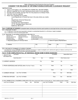
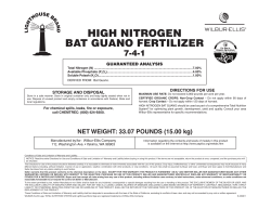


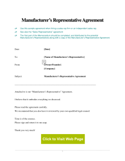
© Copyright 2026