
COVER SHEET Access 5 Project Deliverable
COVER SHEET
Access 5 Project Deliverable
Access 5 Project Office
NASA
P.O. Box 273
Edwards, CA 93523 USA
661-276-2440
661-276-3880 FAX
www.access5.aero
Deliverable Number: HSI010
Title: Step 1: Human System Integration Simulation and Flight Test Progress Report
Filename: HSI010_Step 1_Human System Integration Simulation and Flight Test
Report_FINAL.doc
Abstract:
The Access 5 Human Systems Integration Work Package produced simulation
and flight demonstration planning products for use throughout the program. These
included:
• Test Objectives for Command, Control, Communications
• Pilot Questionnaire for Command, Control, Communications
• Air Traffic Controller Questionnaire for Command, Control, Communications
• Test Objectives for Collision Avoidance
• Pilot Questionnaire for Collision Avoidance
• Plans for Unmanned Aircraft Systems Control Station Simulations
• Flight Requirements for the Airspace Operations Demonstration
Status:
Document Status
Work in Progress
Limitations on use:
This document is an interim deliverable. It represents the Human Systems Integration
functions and performance requirements limited to enroute operations above FL430.
Operations below FL430 and terminal operations have not been addressed in this
document.
Step 1: Human System Integration Simulation and
Flight Test Progress Report
Access 5
November 30, 2005
TABLE OF CONTENTS
ii
The following document was prepared by a collaborative team through the noted work
package. This was a funded effort under the Access 5 Project.
EXECUTIVE SUMMARY ........................................................................................ 5
1
INTRODUCTION........................................................................................... 11
1.1
1.2
2
METHOD................................................................................................ 13
DOCUMENT ORGANIZATION .............................................................. 14
SIMULATION ................................................................................................ 16
2.1
AIRSPACE OPERATIONS SIMULATION (AOS) ................................... 16
2.1.1
AIR TRAFFIC CONTROLLER EVALUATION TOOLS.................... 16
2.2
AIRCRAFT CONTROL STATION (ACS)................................................ 16
2.2.1
HSI FY06 PLANNING ..................................................................... 16
3
FLIGHT TESTS AND DEMONSTRATIONS.................................................. 20
3.1
NATIONAL OCEANIC AND ATMOSPHERIC ADMINISTRATION (NOAA)
PIGGYBACK FLIGHT DEMONSTRATION....................................................... 20
3.1.1
HSI TEST OBJECTIVES AND PILOT EVALUATION TOOLS ........ 20
3.2
COMMAND, CONTROL, AND COMMUNICATIONS (C3) FLIGHT
DEMONSTRATION .......................................................................................... 21
3.2.1
EVALUATION OF VOICE COMMUNICATIONS ............................. 21
3.2.2
HSI TEST OBJECTIVES AND PILOT EVALUATION TOOLS ........ 21
3.3
COLLISION AVOIDANCE (CA) FLIGHT DEMONSTRATION................ 22
3.3.1
SYMBOLOGY GUIDELINES DEFINITION ..................................... 22
3.3.2
HSI TEST OBJECTIVES AND PILOT EVALUATION TOOLS ........ 22
3.3.3
FLIGHT DEMONSTRATION EVALUATION TOOLS ...................... 23
3.4
AIRSPACE OPERATIONS DEMONSTRATION (AOD) ......................... 23
3.4.1
HSI FY06 PLANNING ..................................................................... 23
REFERENCES ..................................................................................................... 24
APPENDIX A: AIR TRAFFIC CONTROLLER QUESTIONNAIRE ....................... 26
APPENDIX B: AIR TRAFFIC CONTROLLER QUESTIONNAIRE RATING SCALE
............................................................................................................................. 28
APPENDIX C: HUMAN SYSTEMS INTEGRATION (HSI) AIRCRAFT CONTROL
STATION (ACS) SIMULATION TEST PLANS – FY06 ......................................... 29
APPENDIX D: HUMAN SYSTEMS INTEGRATION (HSI) TEST OBJECTIVES
FOR NOAA C3 DEMONSTRATION..................................................................... 33
iii
The following document was prepared by a collaborative team through the noted work
package. This was a funded effort under the Access 5 Project.
APPENDIX E. HUMAN SYSTEMS INTEGRATION (HSI) TEST PILOT
QUESTIONNAIRE FOR NOAA C3 DEMONSTRATION ...................................... 42
APPENDIX F: METHOD TO EVALUATE VOICE COMMUNICATIONS QUALITY
............................................................................................................................. 55
APPENDIX G: HUMAN SYSTEMS INTEGRATION (HSI) TEST OBJECTIVES
FOR COMMAND, CONTROL AND COMMUNICATIONS (C3) FLIGHT
DEMONSTRATION .............................................................................................. 58
APPENDIX H:
HUMAN SYSTEMS INTEGRATION (HSI) ACCESS 5 C3
TECHNOLOGY DEMONSTRATION – PILOT QUESTIONNAIRE ....................... 65
APPENDIX I: HSI DISPLAY SYMBOLOGY GUIDELINES FOR SIMULATION OR
FLIGHT TEST FOR COLLISION AVOIDANCE .................................................... 77
APPENDIX J: HUMAN SYSTEMS INTEGRATION (HSI) TEST OBJECTIVES –
COLLISION AVOIDANCE .................................................................................. 115
APPENDIX K: HUMAN SYSTEMS INTEGRATION (HSI) TEST PILOT
QUESTIONNAIRE FOR THE COOPERATIVE CONFLICT AVOIDANCE FLIGHT
DEMONSTRATION ............................................................................................ 122
APPENDIX L: PILOT OBSERVATION LOG - ACCESS 5 COLLISION
AVOIDANCE FLIGHT DEMONSTRATION ........................................................ 127
APPENDIX M:
HUMAN SYSTEMS INTEGRATION (HSI)
AIRSPACE
OPERATIONS DEMONSTRATION (AOD) FLIGHT REQUIREMENTS ............. 128
iv
The following document was prepared by a collaborative team through the noted work
package. This was a funded effort under the Access 5 Project.
EXECUTIVE SUMMARY
Access 5 is a NASA-led project tasked to recommend the policies, procedures, and
functional requirements that will ensure High Altitude Long-Endurance (HALE)
Unmanned Aircraft Systems (UAS) operate as safely as other routine users of the
National Airspace System (NAS). Four phases or “STEPS” are planned to
systematically develop the necessary technology, policies and regulations to enable
manufacturers to apply for Federal Aviation Administration (FAA) certification and
approval needed to operate their civil UAS in the NAS. Current (FY05) effort limits
focus to UASs that operate above 43,000 feet (STEP 1).
In order for UAS to be integrated into the NAS, it is necessary to identify the human
systems integration requirements that ensure safe operations in the NAS. As a result,
the Human System Integration (HSI) Work Package was established within the
overall Access 5 program to address this objective. In FY05, several HSI products
were developed to contribute to overall program objectives.
Human-Systems Integration (HSI) Goals
The primary goal of HSI Work Package (WP) FY05 simulation and flight
demonstration work was to collect human interface data to support validation of
functional requirements for the HSI WP and other WPs. The HSI work performed in
FY05 centered on development of plans for FY05 and FY06 simulations and flight
demonstrations. In FY05, only the Airspace Operations Simulation (AOS) was
conducted and, in this, HSI had a no role. Hence, no reports containing data
analyses, conclusions, or recommendations were published to validate requirements.
These will be produced in FY06.
Process
The process employed by the HSI WP to support simulation and flight demonstration
planning required examination of the Functional Requirements Documents, Test
Objective plans, and other relevant documents for four WPs, namely, Command,
Control, and Communications (C3), Collision Avoidance (CA), Contingency
Management (CM), and Weather Management (Wx). The HSI WP participated in
regular, weekly telecons with these WPs and was represented at coordination
meetings. In addition, the HSI WP attended weekly Simulation WP and Flight Test
WP telecons. From information obtained from these sources, the HSI WP determined
its own goals and goals to support the other WPs.
Results - Simulation
5
The following document was prepared by a collaborative team through the noted work package.
This was a funded effort under the Access 5 Project.
Airspace Operations Simulation (AOS)
In support of Airspace Operations Simulation (AOS) planning, the HSI WP developed
a workload questionnaire to be administered to Air Route Traffic Control Center
(ARTCC) controllers in the AOS. Seven workload questions were developed,
including a new rating scale, which was coordinated with the Simulation WP and the
Policy IPT. In the end, the Simulation WP selected in-house performance evaluation
tools instead of the HSI submission. The HSI WP-developed questionnaire may be
used in future evaluations.
Aircraft Control Station (ACS) Simulation
The HSI WP developed seven simulation plans for the FY06 Aircraft Control Station
(ACS) simulation effort, which will be conducted at the NASA Ames Human Systems
Integration UAV Lab. The submission included two plans for Communications that
focus on beyond-line-of-sight (BLOS) latency guideline validation issues for (1) pilotair traffic controller voice communications and (2) the pilot-vehicle control loop; two
plans for Contingency Management (CM) that are directed at pilot and air traffic
controller human-in-the-loop performance validation issues for (1) lost pilot-air traffic
controller voice communications and (2) lost pilot-unmanned aircraft (UA) datalink;
one plan for Weather Management (WX) concerning the validation of guidelines for
data content required for the UA pilot; and two plans for Collision Avoidance (CA)
involving the CA concept validation of (1) information requirements for the pilot and
(2) pilot response time to a CA system Traffic Alert (TA).
Results - Flight Tests and Demonstrations
National Oceanic and Atmospheric Administration (NOAA) Piggyback Opportunity
In early 2005, Access 5 learned of an unmanned aircraft system (UAS)-based
science mission to be operated under the auspices of the National Oceanic and
Atmospheric Administration (NOAA). Access 5 viewed this mission as a piggyback
opportunity to observe and collect data for specific Access 5 requirement and
concept validation purposes. The HSI WP performed a cost-benefit study and found
that its UA pilot and air traffic controller BLOS voice communications flight
demonstration goals for Step 1 could be completely satisfied with data collection from
this operation. The HSI WP developed a test objectives document which was
submitted to the Flight Test IPT. It contained four General Test Objectives (GTO),
multiple Specific Test Objectives (STO), Measures of Performance (MOP), Success
Criteria, Evaluation Criteria, definition of Final Data products, and Data
6
The following document was prepared by a collaborative team through the noted work package.
This was a funded effort under the Access 5 Project.
Requirements. The air traffic controller questionnaire developed for the AOS was
modified slightly to make it appropriate for use in evaluating in-the-ARTCC controller
workload. In the end, the Program made the decision not to pursue the piggyback
opportunity. However, in the planning process, HSI had developed a voice
communications questionnaire for UA pilots that would be of use in later work.
Command, Control, and Communications (C3)
Command, Control, and Communications (C3) WP FY05 plans included a flight
demonstration scheduled for September 2005 to evaluate Step 1 aspects of C3. The
HSI WP evaluated the C3 test plan and determined the need to obtain requirements
validation data for UA pilot-air traffic controller voice communications, and C2 pilotUA datalink. As the scope of this flight demonstration was very close to that of the
NOAA exercise, the HSI WP required little time or funding to modify its earlier NOAA
test objectives and questionnaire documents to satisfy C3 HSI WP requirements.
In support of the development of voice communications quality evaluations for pilots
and controllers, a literature survey was performed to identify methodologies to
evaluate voice quality. A modified Mean Opinion Score (MOS) was developed,
specific to Access 5 HSI requirements, and distributed within the Program. This was
an integral part of the questionnaires.
As C3 plans matured, the C3 WP and program determined that it would be
impractical to develop scenarios that involved beyond-line-of-sight C3 between the
pilot and FAA ATC. As, the HSI WP had previously evaluated line-of-sight C3 (in the
Alaska flight demonstration), the deletion of the beyond-line-of-sight goals eliminated
the need for HSI involvement in the C3 demonstration.
Collision Avoidance (CA)
CA WP FY05 plans included a flight demonstration scheduled for September 2005 to
evaluate Step 1 aspects of CA.
To support preparatory to Systems Integration Lab (SIL) simulation efforts and flight
demonstration, the CA WP required CA display symbology and pilot procedures. This
task was performed by the HSI WP, beginning with a literature review of existing CA
concepts, symbology, and procedures. Thereafter the HSI WP developed a set of
data tailored to the CA test plan to support CA flight demonstration goals. Symbology
guidelines were developed for pilot alerting, avoidance maneuver command
guidance, and traffic display formats. This information was used by Lockheed-Martin
in Ft. Worth to develop CA symbology and CA concepts and, later, by the Northrop7
The following document was prepared by a collaborative team through the noted work package.
This was a funded effort under the Access 5 Project.
Grumman Corporation in their SIL. Output from the SIL is to be hosted in the ACS
used in the September 2005 flight demonstration.
The HSI WP also developed a test objectives document that outlined flight
demonstration goals for validation of pilot-in-the-loop aspects of the CA concept. The
document contained two GTO, multiple STO, MOP, Success Criteria, Evaluation
Criteria, definition of Final Data products, and Data Requirements. In addition, as
required by the HSI test plan, collection was required of pilot performance data to
support the requirements validation effort. A number of pilot questionnaires were
developed, culminating in a four-question format. However, as the CA WP refined its
test plans and objectives, its last revision eliminated requirements for HSI data
collection. The CA WP had structured its demonstration to collect data on the
performance of its CA hardware and software designs to verify its functional
requirements. As such, the demonstration was not conducive to the evaluation of the
interface between the pilot and CA system. Nevertheless, HSI WP planning led to the
production of a number of documents that will facilitate future HSI-CA simulation and
flight demonstration efforts.
Airspace Operations Demonstration (AOD)
Flight Test WP FY05 plans include a scheduled flight demonstration in early FY06 to
demonstrate Step 1 aspects of UAS functional requirements. The HSI WP developed
and submitted AOD Flight Requirements to the Flight Test WP to support
demonstration of its high-level functional requirements. Included are four Flight
Requirements for C3, one for CA, and one for CM.
Summary
In FY05, the HSI WP produced simulation and flight demonstration planning products
that are available for future use.
• Test Objectives for C3
• Pilot Questionnaire for C3
• Air Traffic Controller Questionnaire for C3
• Test Objectives for CA
• Pilot Questionnaire for CA
• Plans for ACS
• Flight Requirements for AOD
As the ground work has been laid in FY05, modification and tailoring of planning
documents for new efforts will require minimal time and funding. The bulk of HSI work
for FY06 will be participation in simulations and flight demonstrations, data analyses,
8
The following document was prepared by a collaborative team through the noted work package.
This was a funded effort under the Access 5 Project.
conclusions development, and formulation of recommendations leading to validation
of HSI functional requirements.
9
The following document was prepared by a collaborative team through the noted work package.
This was a funded effort under the Access 5 Project.
ACRONYMS
AOS
AOD
ARTCC
ATC
C3
CA
CM
BLOS
DOD
FAA
FL
GTO
HALE
HSI
IFR
IPT
NOAA
NAS
NASA
MOP
MOS
SIL
STO
SWPCS
TA
WP
UA
UAS
Airspace Operations Simulation
Airspace Operations Demonstration
Air Route Traffic Control Center
Air Traffic Control
Command, Control, and Communications
Collision Avoidance
Contingency Management
Beyond Line of Sight
Department of Defense
Federal Aviation Administration
Flight Level
General Test Objective
High Altitude Long Endurance
Human Systems Integration
Instrument Flight Rules
Integrated Product Team
National Oceanic and Atmospheric Administration
National Airspace System
National Aeronautics and Space Administration
Measure of Performance
Mean Opinion Score
Systems Integration Lab
Specific Test Objective
Situational Weather Product Classification & Selection
Traffic Alert
Work Package
Unmanned Aircraft
Unmanned Aircraft System
10
The following document was prepared by a collaborative team through the noted work package.
This was a funded effort under the Access 5 Project.
1
INTRODUCTION
Access 5 is a NASA-led project tasked to recommend the policies, procedures, and
functional requirements that will ensure High Altitude Long-Endurance (HALE)
Unmanned Aircraft Systems (UAS) operate as safely as other routine users of the
National Airspace System (NAS). Four phases or “STEPS” are planned to
systematically develop the necessary technology, policies and regulations to enable
manufacturers to apply for Federal Aviation Administration (FAA) certification and
approval needed to operate their civil UAS in the NAS. Current (FY05) effort limits
focus to UASs that operate above 43,000 feet (STEP 1).
The Access 5 Project is taking an incremental approach for introducing UAS into the
NAS. HALE was chosen as the focus because HALE aircraft are mature systems and
can operate above most air traffic, making this class of UAS the safest for initial
introduction into the NAS. It is believed, however, that Access 5 will also lay the
groundwork for the future introduction of other classes of UAS. Access 5 will achieve
its goals by systematically addressing access to the NAS in four discrete steps of
increasing complexity and capability:
Step 1: Routine Operations above Flight Level (FL) 430 through PreCoordinated Airspace
Step 2: Routine Operations above FL 180 through Pre-coordinated Airspace
with Emergency Landings at Pre-coordinated Airports
Step 3: Routine Operations above FL 180 through C, D, and E Airspace with
Emergency Landing at Pre-coordinated Airports
Step 4: Routine Operations above FL 180 through C, D, and E Airspace with
Emergency Landings at any UAS Designated Airport
In order for UAS to be integrated into the NAS, it is necessary to identify the human
systems integration requirements that ensure safe operations in the NAS. As a result,
the Human System Integration (HSI) Work Package was established within the
overall Access 5 program to address this objective. In FY05, several HSI products
were developed to contribute to overall program objectives. The FY05 HSI effort
followed a standard, HSI process methodology that produced the following
deliverables (Figure 1):
Deliverable 1: Human System Integration Step 1 Functional Requirement Document
(FRD)
11
The following document was prepared by a collaborative team through the noted work package.
This was a funded effort under the Access 5 Project.
Deliverable 2: Human System Integration (HSI) Step 1 Design Guidelines for the
Unmanned Aircraft System (UAS) Ground Control Station
Deliverable 3: High Altitude Long Endurance (HALE) Unmanned Aircraft System
(UAS) Pilot Rating Criteria (Draft)
Deliverable 4: HSI Requirements and Guidelines for Experimental Certification of the
Unmanned Aircraft System
Deliverable 5: Human Systems Integration Step 1 Pilot-Technology Interface
Requirements
Deliverable 5a: Human Systems Integration Step 1 Pilot-Technology Interface
Requirements for Command, Control, and Communications (C3) in Unmanned
Aircraft Systems
Deliverable 5b: Human Systems Integration Step 1 Pilot-Technology Interface
Requirements for Collision Avoidance in Unmanned Aircraft Systems
Deliverable 5c: Human Systems Integration Step 1 Pilot-Technology Interface
Requirements for Contingency Management System in Unmanned Aircraft
Systems
Deliverable 5d: Human Systems Integration Step 1 Pilot-Technology Interface
Requirements for the Weather System in Unmanned Aircraft Systems
Deliverable 6: Human Systems Integration Support to Simulation and Flight
Test for Step 1
12
The following document was prepared by a collaborative team through the noted work package.
This was a funded effort under the Access 5 Project.
Collect Required
UAS, FAA, and
Access 5 Data
Develop HSI
Guidelines
Del 2: HSI
Guidelines
Perform
Simulation and
Flight Test
Define HSI Functional
Requirements
Del 1: Func Req Doc
Derive Pilot
KSAs
Del 3: KSA
Report
Identify
Interface
Technology
Requirements
Del 5: Tech I/F Req
Establish HSI
Certification
Approach
Del 4: Cert
Methodology
Provide Input
to Other IPTs
Del 6: Support to SIM/FT
Figure 1. FY05 HSI Process and Deliverable Overview
1.1
METHOD
The method used in HSI WP efforts related to simulation and flight demonstration
varied according to the specific goals and scope of individual evaluations.
Flight demonstration and simulation planning for Command, Control, and
Communications (C3), Collision Avoidance (CA), Contingency Management (CM),
and Weather Management (Wx) required examination of those WP’s Functional
Requirements Documents (FRD), Test Plans, and other relevant documents.
Coordination meetings took place to further gain insight into the requirements for HSI
flight demonstration and simulation planning. From this information, the HSI WP
determined the goals and scope, thereby allowing it to define its own goals to support
the other WPs. The output of this process typically included an HSI Test Objectives
document, data collection tools (such as Pilot Questionnaire, Air Traffic Controller
Questionnaire), and other relevant materials (such as display symobology guidelines
for CA).
13
The following document was prepared by a collaborative team through the noted work package.
This was a funded effort under the Access 5 Project.
The FY05 planning efforts were targeted at the simulation Aircraft Control Station)
(ACS) slated to start in FY06. Similarly, flight demonstrations for C3, CM and
Airspace Operations Demonstration (AOD) are also planned to take place in FY06.
In FY05, no simulations or flight demonstrations took place in which HSI had a role.
Hence, no reports containing data analysis, conclusions, or recommendations were
published. This will occur in FY06.
1.2
DOCUMENT ORGANIZATION
This document is organized into the following sections:
Section 1 - Introduction: States the purpose, scope, background, and methodology
used for this requirements document, including its relationship to the Access 5
project.
Section 2 – Simulations: Describes FY05 HSI planning, documentation, and
coordination within Access 5 for simulations.
Section 3 – Flight Tests and Demonstrations: Describes FY05 HSI planning,
documentation, and coordination within Access 5 for flight tests and demonstrations.
Appendix A – Air Traffic Controller Questionnaire
Appendix B – Rating Scale for Use with the Air Traffic Controller Questionnaire
Appendix C – Human Systems Integration (HSI)
Simulation Test Plans – FY06
Aircraft Control Station (ACS)
Appendix D – Human Systems Integration (HSI) Test Objectives for NOAA C3
Demonstration
Appendix E – Human Systems Integration (HSI) Test Pilot Questionnaire for NOAA
C3 Demonstration
Appendix F – Method to Evaluate Voice Communications Quality
Appendix G – Human Systems Integration (HSI) Test Objectives for Command,
Control and Communications Flight Demonstration
Appendix H – Human Systems Integration (HSI) Access 5 C3 Technology
Demonstration – Pilot Questionnaire
14
The following document was prepared by a collaborative team through the noted work package.
This was a funded effort under the Access 5 Project.
Appendix I – Human Systems Integration (HSI) HSI Display Symbology Guidelines
for Simulation or Flight Test for Collision Avoidance
Appendix J – Human Systems Integration (HSI) Test Objectives – Collision
Avoidance
Appendix K – Human Systems Integration (HSI) Test Pilot Questionnaire for CCA
Flight Demonstration
Appendix L – Pilot Observation Log - Access 5 Collision Avoidance Flight
Demonstration
Appendix M – Human Systems Integration (HSI)
Demonstration (AOD) Flight Requirements
Airspace
Operations
References
15
The following document was prepared by a collaborative team through the noted work package.
This was a funded effort under the Access 5 Project.
2
SIMULATION
2.1
2.1.1
AIRSPACE OPERATIONS SIMULATION (AOS)
AIR TRAFFIC CONTROLLER EVALUATION TOOLS
Part of the AOS effort at NASA Ames included plans for the evaluation of air traffic
controller workload. While NASA Ames has performed this type of work for many
years, Access 5 had requested HSI to develop a workload questionnaire for air traffic
controllers. The product was to be compared to similar NASA Ames workload
measures to determine whether to use one or both.
At this time, Access 5 was making plans for evaluation of air traffic controller
workload for voice communications in flight demonstrations. Therefore, it was
planned that the HSI workload questionnaire would be administered to Air Route
Traffic Control Center (ARTCC) controllers that would be in communication with the
unmanned aircraft (UA) pilot.
Seven workload questions were developed and coordinated with NASA Ames and
the Policy IPT [“Access 5 – Questionnaire for Air Traffic Controllers Feb 16 05”
(Appendix A)]. A new rating scale was developed that was a modification of the
Cooper-Harper 10-point rating scale. The scale was documented in “Access 5 Rating
Scale for Air Traffic Controllers Feb 16 05” (Appendix B).
After evaluation by Access 5, the Simulation WP selected an existing workload
questionnaire rather than the one developed by HSI. Flight demonstrations aimed at
evaluating air traffic controller workload were not realized and, hence, the
questionnaire was not used. Nevertheless, the effort placed into developing the
questionnaire and rating scale was worthwhile, for this tool is available for any future
Access 5 voice communications flight demonstration or simulation involving air traffic
controllers. No additional HSI costs will be incurred to develop another questionnaire.
2.2
2.2.1
AIRCRAFT CONTROL STATION (ACS)
HSI FY06 PLANNING
The HSI WP developed seven simulation plans for the FY06 ACS simulation effort.
This effort is headed by the Simulation WP with the goal, over several years, of
evaluating technology and procedures for the UA pilot and air traffic controllers using
16
The following document was prepared by a collaborative team through the noted work package.
This was a funded effort under the Access 5 Project.
human-in-the-loop simulation. The work will be conducted at the NASA Ames
Human Systems Integration UAV Lab.
After a review of relevant documents from other WPs, HSI developed ACS simulation
plans, which are documented in “HSI AVCS Simulation Test Plans for FY06 Jun 8
05” (Appendix C)1. The submission included two plans for Communications; two
plans for Contingency Management (CM); one plan for Weather Management (WX);
and two plans for Collision Avoidance (CA).
The plans for voice communications focus on beyond-line-of-sight (BLOS) latency
issues. Line-of-sight issues are not included because they had been successfully
evaluated in the 2004 Alaska Flight demonstration2.
Simulation 1 will determine the operational effects of latency on voice
communications between UA pilots and air traffic controllers and determine a latency
or latencies below which acceptable voice communications are realized. Today, voice
communications in the National Airspace System (NAS) have effectively zero latency.
As a result, communications between two parties takes place unencumbered by
delays in voice transmission. This leads to effective communications, subject to non1
Command and Control Communications, Step 1, Functional Requirements Document, Access 5
WP6 Team, Version 3.01. June 10, 2005.
Contingency Management Requirements Document. (Preliminary Version) September 30, 2004
(Revision D − 03/31/2005)
HALE UAS Command and Control Communications Functional Requirements. May 31, 2005.
NASA Access 5 WP6 Team, HALE ROA ATC Communications Step 1 Functional and Performance
Requirements. Report No. TR04045. September 30, 2004.
NASA Access 5 WP6 Team, HALE ROA Command and Control Communications Functional and
Performance Requirements. Sep 2004.
NASA Access 5 WP1 and WP2 Teams, Sense and-Avoid Equivalent Level of Safety Definition for
Unmanned Aircraft Systems, rev. 9, September 23, 2004.
NASA Access 5 WP6 Team, Cooperative Conflict Avoidance Functional Requirements for Step 1—
HALE ROA Flight above FL400, Draft, Rev. 2, September 30, 2004.
Weather Requirements & Procedures for Step 1. March 2005.
2
Access 5 Program Observations of the Alaska Mariner/Altair UAV System Concept Evaluation
Operational Test and Evaluation of a Mariner (Modified Predator B) in the Alaska Area Of
Responsibility. September 2004.
17
The following document was prepared by a collaborative team through the noted work package.
This was a funded effort under the Access 5 Project.
latency issues. Research shows that there is an association between latency
magnitude (in seconds) and acceptability of communications, flight safety, air traffic
delay, and pilot and controller workload.
Simulation 2 plans focus on the BLOS datalink delay impact on manual control of a
UA. It is expected that some UAs will be manually controlled, either as its primary
flight control mode or as a backup mode. BLOS latencies are of a larger magnitude
than that required for safe UA manual control3. This simulation will examine various
latencies to determine the effect on the pilot-vehicle control loop.
Simulation 3 will evaluate contingency management (CM) for pilot loss of
communications with air traffic control (ATC). Today, pilots who loss communication
while on an Instrument Flight Rules (IFR) flight plan are bound by Federal Aviation
Regulations (FAR) Section 91.185 to follow a specific course of action. Access 5 has
not agreed that this is appropriate for UA operations. As a result, this simulation will
examine procedural options for UA flight during loss of communications, observe pilot
tasks and impact on ATC. Results will indicate the impact on UA safety, air traffic
safety, air traffic controller workload, and safety of nearby aircraft.
Simulation 4 will assess CM for loss of datalink between the UA Aircraft Control
station (ACS) and UA. Today, there is no analogy in inhabited aircraft for this type of
failure. However, a parallel has been drawn by some that the procedure for lost voice
communications may be applied here. Access 5 has not agreed that this is
appropriate for UA operations. As a result, this simulation will examine procedural
options for UA flight during loss of datalink, with the focus placed primarily on impact
on ATC and safe operation of the UA. Results will indicate the impact on UA safety,
air traffic safety, air traffic controller workload, and safety of nearby aircraft.
Simulation 5 will evaluate the HSI to the Access 5 concepts for CA. It will focus on
CA performance as a function of information presented to the pilot. Information
display options are (1) aural alert and plan view traffic display and (2) aural alert, plan
view traffic display, and avoidance maneuver guidance display, and (3) plan view
traffic display only. Analysis of the literature show that option 2 above is required4.
However, the Access 5 program has not agreed this position and, hence, the
simulation evaluation will provide objective data to evaluate the various information
display and pilot decision-making options.
3
National Research Council. Aviation Safety and Pilot Control. – Understanding and Preventing
Unfavorable Pilot-Vehicle Interactions. 1997.
4
Human Systems Integration Pilot-Technology Interface Requirements for Cooperative Conflict
Avoidance. Access 5 Program. August 2005.
18
The following document was prepared by a collaborative team through the noted work package.
This was a funded effort under the Access 5 Project.
Simulation 6 will investigate the time required for a pilot to respond to a CA system
Traffic Alert (TA).5 Results will include a recommendation for maximum allowable
pilot response time to a CA alert for en route flight above FL430.
The objective of Simulation 7 is to demonstrate the expected enhanced hazardous
weather avoidance performance of pilots using the SWPCS concept at the ACS. The
SWPCS concept utilizes a weather display capability that separates integrated,
“nowcasted” weather products from other weather information, providing them to the
pilot under a separate menu selection. These graphical products contain certain
attributes that make them spatially/temporally more appropriate for operational
planning decision-making. Operators that utilize these products, along with other
sources of weather information, may make better hazardous weather avoidance
decisions than operators utilizing other products with temporal latencies or spatial
inaccuracies.
5
An alert requiring an avoidance maneuver.
19
The following document was prepared by a collaborative team through the noted work package.
This was a funded effort under the Access 5 Project.
3
FLIGHT TESTS AND DEMONSTRATIONS
3.1
3.1.1
NATIONAL OCEANIC AND ATMOSPHERIC ADMINISTRATION
(NOAA) PIGGYBACK FLIGHT DEMONSTRATION
HSI TEST OBJECTIVES AND PILOT EVALUATION TOOLS
In early 2005, Access 5 learned of a UAS-based science mission under the auspices
of the National Oceanic and Atmospheric Administration (NOAA). This mission
involved flight southwest of the Los Angeles area to distances of up to 1000 nautical
miles (nm) for the purpose of collecting data on winds aloft and jet stream activity.
Access 5 viewed this mission as a piggyback opportunity to observe and collect data
for specific Access 5 purposes. Part of the process the Program employed in
determining the viability of performing the piggyback operation was a cost-benefit
study. The HSI WP performed such a study and found that its UA pilot and air traffic
controller BLOS voice communications flight demonstration goals for Step 1 could be
completely satisfied through this operation. That is, there would be not a need for HSI
to replicate the work in the future.
A test plan was developed and submitted to the Flight Test IPT that contained four
General Test Objectives (GTO), multiple Specific Test Objectives (STO), Measures
of Performance (MOP), Success Criteria, Evaluation Criteria, definition of Final Data
products, and Data Requirements (“Human Systems Integration (HSI) Test
Objectives for NOAA C3 Flight Demonstration Mar 2 05 rev 1”) (Appendix D). The air
traffic controller questionnaire developed for the AOS was modified slightly to make it
appropriate for use in evaluating ARTCC controller workload. A new, unique UA pilot
14-question pilot questionnaire was also developed to assess voice communications,
“Human Systems Integration (HSI) Test Pilot Questionnaire for the NOAA C3 Flight
Demonstration Mar 7 05” (Appendix E). This questionnaire was based in part on an
HSI analysis of methods for voice quality evaluation (see 3.2.1).
In the end, the Program made the decision not to pursue the piggyback opportunity.
However, in the planning process, HSI had developed a voice communications
questionnaire for UA pilots that would be of use in later work.
20
The following document was prepared by a collaborative team through the noted work package.
This was a funded effort under the Access 5 Project.
3.2
3.2.1
COMMAND, CONTROL, AND COMMUNICATIONS (C3) FLIGHT
DEMONSTRATION
EVALUATION OF VOICE COMMUNICATIONS
C3 WP FY05 plans included a flight demonstration in September 2005 to evaluate
Step 1 aspects of command, control, and communications. The HSI WP evaluated
the scope of the C3 test plan and determined the need to examine the interface
between the UA pilot and air traffic controller for voice communications. In addition, it
was deemed necessary to examine the pilot interface to the uplink- and downlinkprovided information, as this is the only source of command, control, and feedback
available to the pilot to know vehicle status and affect its control.
In support of the development of voice communications quality evaluations by pilots
and controllers, a literature survey was performed to identify methodologies to
evaluate voice quality. The Mean Opinion Score (MOS) was found to be most
commonly used and valid tool. Due to a number of technical factors, it was modified
to tailor it to specific Access 5 HSI requirements. The analysis and rationale for
modification are described in “Method to Evaluate Voice Communications Quality –
Preliminary Analysis Jan 11 05” (Appendix F).
As C3 plans matured, the C3 WP and program determined that it would be
impractical to develop scenarios that involved beyond-line-of-sight C3 between the
pilot and FAA ATC. As, the HSI WP had previously evaluated line-of-sight C3 (in the
Alaska flight demonstration), the deletion of the beyond-line-of-sight goals eliminated
the need for HSI involvement in the C3 demonstration.
3.2.2
HSI TEST OBJECTIVES AND PILOT EVALUATION TOOLS
A test plan was developed and submitted to the Flight Test WP that contained four
GTO, multiple STO, MOP, Success Criteria, Evaluation Criteria, definition of Final
Data products, and Data Requirements (“Human Systems Integration (HSI) Test
Objectives for C3 Flight Demonstration Apr 6 05”) (Appendix G). The air traffic
controller questionnaire developed for the AOS was modified slightly to make it
appropriate for use in evaluating ARTCC controller workload.
Results of the voice quality assessment analysis had provided a modified MOS for
use in the NOAA (see 3.1) and C3 flight demonstrations. The modified MOS was
combined with additional voice and datalink-related questions to form to complete
21
The following document was prepared by a collaborative team through the noted work package.
This was a funded effort under the Access 5 Project.
HSI C3 pilot questionnaire. The pilot questionnaire developed for the AOS was
reduced from 14 questions to 12 questions to make it appropriate for use in
evaluating pilot controller workload (“Human Systems Integration (HSI) Test Pilot
Questionnaire for C3 Flight Demonstration Jul 23 05”) (Appendix H).
[The modified MOS was not applied to the air traffic controller questionnaire originally
developed for the AOS (see 2.1), as it had been determined that Access 5 Program
personnel would be unable to administer questionnaires to controllers.]
3.3
3.3.1
COLLISION AVOIDANCE (CA) FLIGHT DEMONSTRATION
SYMBOLOGY GUIDELINES DEFINITION
CA WP FY05 plans included a flight demonstration in September 2005 to evaluate
Step 1 aspects of collision avoidance. The CA WP required CA display symbology
and procedures to support its effort and requested the HSI WP to provide support.
The HSI WP performed a literature review of existing CA concepts, symbology, and
procedures. Thereafter it developed a set of data tailored to the CA test plan to
support CA flight demonstration goals. Guidelines include information on alerting,
avoidance maneuver command guidance, and traffic display formats.
These data were communicated to the CA WP, and in particular, directly to the
LMCO CA organization in Ft. Worth, TX, that had responsibility to convert these
symbology guidelines into a working simulation. HSI symbology concepts are
documented in a 37 Power Point slide presentation, “HSI Display Symbology
Guidelines for Simulation or Flight Test for CA Mar 8 05” (Appendix I).
3.3.2
HSI TEST OBJECTIVES AND PILOT EVALUATION TOOLS
As part of the Flight Test and CA WP FY05 flight demonstration planning effort, the
HSI WP evaluated the scope of the CA test plan and determined the need to
examine the interface between the UA pilot and CA displays, controls, and
procedures. A test plan was developed and submitted to the Flight Test and CA WP
that contained two GTO, multiple STO, MOP, Success Criteria, Evaluation Criteria,
definition of Final Data products, and Data Requirements (“Human Systems
Integration (HSI) Test Objectives for CCA Flight Demonstration Apr 5 05”) (Appendix
J). In addition, as required by the HSI test plan, collection of pilot observation data of
their CA experience was required. A four-question, pilot questionnaire was developed
22
The following document was prepared by a collaborative team through the noted work package.
This was a funded effort under the Access 5 Project.
for this purpose entitled, “Human Systems Integration (HSI) Test Pilot Questionnaire
for CCA Flight Demonstration May 10 05” (Appendix K).
The CA WP refined its test plans and objectives with the last revision eliminating HSI
data collection. The CA WP had structured its demonstration to collect data on the
performance of its CA hardware and software designs to verify its functional
requirements. As such, the demonstration was not designed to evaluate the interface
between the pilot and CA system.
3.3.3
FLIGHT DEMONSTRATION EVALUATION TOOLS
While no HSI evaluations were planned for the CA flight demonstration, the CA WP
required a method for the pilot to log abnormal occurrences or note unusual
observations. The purpose of this was to have a record that could be compared to
recorded data and provide insight into the reasons for data collected. The HSI WP
developed, and submitted to the CA WP, a short, four-question observation log form
for this purpose, “Pilot Observation Log for CCA Flight Demonstration May 25 05”
(Appendix L).
3.4
3.4.1
AIRSPACE OPERATIONS DEMONSTRATION (AOD)
HSI FY06 PLANNING
Flight Test WP FY05 plans included a flight demonstration in early 2006 to
demonstrate Step 1 aspects of unmanned aircraft system (UAS) functional
requirements. Each WP was assigned the task to submit AOD Flight Requirements
for flight demonstration of its high-level functional requirements. The HSI WP
provided several inputs to the Flight Test WP including, “Human Systems Integration
(HSI) Flight Requirements for Airspace Operations Demonstration Jul 20 05”
(Appendix M). Included are four Flight Requirements for C3, one for CA, and one for
CM.
23
The following document was prepared by a collaborative team through the noted work package.
This was a funded effort under the Access 5 Project.
REFERENCES
Access 5 Command, Control, and Communications (C3) Work Package Step 1 Flight
Demo Data Analysis Plan. June 29, 2005.
Access 5 HSI Top Level Functional Requirements SEIT Review, January 7, 2005
Access 5 Program Observations of the Alaska Mariner/Altair UAV System Concept
Evaluation Operational Test and Evaluation of a Mariner (Modified Predator B) in the
Alaska Area of Responsibility. September 2004.
Access 5 Technology Demonstration Command, Control, and Communication Test
Objectives. June 29, 2005.
Command and Control Communications, Step 1, Functional Requirements
Document, Access 5 WP6 Team, Version 3.01. June 10, 2005.
Work Package 5, Contingency Management, Contingency Management
Requirements Document (Preliminary Version). September 30, 2004 (Revision D −
03/31/2005).
HALE UAS Command and Control Communications Functional Requirements. May
31, 2005.
Human Systems Integration Pilot-Technology Interface Requirements for
Cooperative Conflict Avoidance. Access 5 Program. August 2005.
NASA Access 5 WP6 Team, Cooperative Conflict Avoidance Functional Requirements
for Step 1—HALE ROA Flight above FL400, Draft, Rev. 2, September 30, 2004.
NASA Access 5 WP6 Team, HALE ROA ATC Communications Step 1 Functional
and Performance Requirements. Report No. TR04045. September 30, 2004.
NASA Access 5 WP6 Team, HALE ROA Command and Control Communications
Functional and Performance Requirements. 30 Sep 2004, pp. 12-20.
NASA Access 5 WP1 and WP2 Teams, Sense and-Avoid Equivalent Level of Safety
Definition for Unmanned Aircraft Systems, rev. 9, September 23, 2004.
Step 1: Functional Requirements Document, Preliminary Draft. May 2005
24
The following document was prepared by a collaborative team through the noted work package.
This was a funded effort under the Access 5 Project.
Step 1: Human System Integration (HSI) Functional Requirements Document (FRD),
Version 1.1. July 2005
National Research Council. Aviation Safety and Pilot Control – Understanding and
Preventing Unfavorable Pilot-Vehicle Interactions. National Academy Press.
Washington, DC. 1997.
Weather Requirements & Procedures for Step 1, Pg. 3-4. 9 March 2005.
25
The following document was prepared by a collaborative team through the noted work package.
This was a funded effort under the Access 5 Project.
APPENDIX A: AIR TRAFFIC CONTROLLER QUESTIONNAIRE
------------------------------------------------------------------------------------AIR TRAFFIC CONTROLLER QUESTIONNAIRE
February 16, 2005
COMMUNICATIONS
For Communications questions, the controller should consider the following elements
in providing an answer: volume of transmission, background noise heard through the
headset, understandability of pilot, transmission quality, need to repeat
transmissions, and time delays.
1. What was the ease or difficulty in receiving communication from the aircraft?
2. What was the ease or difficulty in transmitting acknowledgements and/or
clearances to the aircraft?
TRAFFIC
For Traffic questions, the controller should consider the following elements in
providing an answer: ability or inability of pilot to understand point out information,
and limitations of the aircraft to find traffic (as explained by the pilot).
3. What was the ease or difficulty in pointing out traffic to the vehicle?
4. What was the ease or difficulty in the vehicle finding the traffic?
ATC CLEARANCE COMPLIANCE
For ATC Clearance Compliance questions, the controller should consider the
following elements in providing an answer: level of compliance or non-compliance
with clearance, timeliness of pilot readback, timeliness of aircraft response, impact on
traffic of aircraft performance, and impact of aircraft movement (if any) on traffic flow.
26
The following document was prepared by a collaborative team through the noted work package.
This was a funded effort under the Access 5 Project.
5. What was the ease or difficulty in getting the vehicle to change its flight path
by issuing a clearance (altitude, heading, route, speed, etc.)?
6. What was the ease or difficulty in dealing continuously with the aircraft?
WEATHER
For the Weather question, the controller should consider the following elements in
providing an answer: obtaining information on cloud bases and tops; icing location,
level and severity; and turbulence location and intensity.
7. What was the ease or difficulty in obtaining PIREPS on weather?
27
The following document was prepared by a collaborative team through the noted work package.
This was a funded effort under the Access 5 Project.
APPENDIX B: AIR TRAFFIC CONTROLLER QUESTIONNAIRE
RATING SCALE
------------------------------------------------------------------------------------RATING SCALE FOR USE WITH AIR TRAFFIC
CONTROLLER QUESTIONNAIRE
February 16, 2005
LEGEND:
Rating
Ease/Difficulty
Demand Level
1
Excellent
No controller effort required
2
Good;
Negligible Controller effort not a factor
deficiencies
3
Fair/Mild deficiencies
Minimal controller effort required for
desired performance
4
Minor deficiencies
Moderate controller effort is required for
desired performance
5
Objectionable deficiencies Considerable controller effort required
for desired performance
6
Very objectionable
Extensive controller effort required for
deficiency
desired performance
7
Major deficiencies
Adequate performance not attainable
with maximum effort
8
Major deficiencies
Minor errors experienced with maximum
effort
9
Major deficiencies
Major errors experienced with maximum
effort
10
Impossible/Unacceptable
Controller cannot complete task
28
The following document was prepared by a collaborative team through the noted work package.
This was a funded effort under the Access 5 Project.
APPENDIX C: HUMAN SYSTEMS INTEGRATION (HSI) AIRCRAFT
CONTROL STATION (ACS) SIMULATION TEST PLANS – FY06
HUMAN SYSTEMS INTEGRATION (HSI) AIRCRAFT
CONTROL STATION (ACS) SIMULATION TEST PLANS –
FY06
JULY 20, 2005
HSI AVCS Simulation Test Plans – FY06
Simulation 1:
Title – Human-Systems Integration Simulation Study of BLOS Voice Communications
Latency: An Operational Assessment of Communications between an ROA Pilot and
Air Traffic Control
Objective – Determine the operational impact threshold for BLOS voice
communications latency between an ROA pilot and air traffic controller for operations
above FL180.
Description – Examine various latencies to determine the effect(s) on
communications. A threshold will be defined, above which, the communications delay
will be unacceptably large and, below which, the delay will be acceptable.
Simulation 2:
Title - Human-Systems Integration Simulation Study of BLOS Data Communications
Latency: An Operational Assessment of Data Link Latency in Manual Control of an
ROA
Objective – Determine the operational impact threshold for BLOS data
communications latency between an ROA pilot and ROA vehicle for operations
above FL180.
Description – Examine various latencies to determine the effect on the pilot-vehicle
control loop. A threshold or thresholds will be determined above which pilot ability to
send flight control commands to the aircraft and receive feedback, will not allow for
29
The following document was prepared by a collaborative team through the noted work package.
This was a funded effort under the Access 5 Project.
satisfactory aircraft control, and below which, satisfactory control can be achieved.
This is specific to manual flying for specific ROAs.
Simulation 3:
Title – Human-Systems Integration Simulation Study of Loss of Communications: An
Operational Assessment of ROA Operations, Pilot Tasks, and Air Traffic Control
Impacts.
Objective – Examine options for loss of communications procedures between the
ROA pilot and air traffic control for operations above FL180.
Description – Examine procedural options for ROA flight during loss of
communications. Observe pilot tasks and impact on ATC. Procedural options include
(1) diversion to nearest suitable airport, (2) return to origin, and (3) continuance to
destination.
Simulation 4:
Title – Human-Systems Integration Simulation Study of Loss of Data Link: An
Operational Assessment of ROA Operations, Pilot Tasks, and Air Traffic Control
Impacts.
Objective – Examine options for loss of link procedures between the ROA pilot and
ROA for operations above FL180.
Description – Examine procedural options for ROA flight during loss of link. Observe
pilot tasks and impact on ATC. Procedural options include (1) diversion to nearest
suitable airport, (2) return to origin, and (3) continuance to destination.
Simulation 5:
Title – Human-Systems Integration Simulation Study of Collision Avoidance: An
Operational Assessment of Pilot Behavior for a Collision Avoidance Concept
Objective – Determine if avoidance maneuver guidance information is necessary for
satisfactory collision avoidance performance for operations above FL180.
Description – For the Access 5 collision avoidance concept(s), evaluate collision
avoidance performance as a function of information presented to the pilot.
30
The following document was prepared by a collaborative team through the noted work package.
This was a funded effort under the Access 5 Project.
Information display options are (1) aural alert and plan view display and (2) aural
alert, plan view display, and avoidance maneuver guidance display.
Simulation 6:
Title – Human-Systems Integration Simulation Study of Pilot Reaction Time: An
Operational Assessment of Required Pilot Reaction Time for a Collision Avoidance
Concept
Objective – Determine the required pilot reaction time for the Access 5 concept(s) for
collision avoidance for operations above FL180.
Description – For the Access 5 collision avoidance concept(s), measure pilot reaction
time in an operational environment. Thereafter, determine if the observed reaction
time data are compatible with collision avoidance concepts. If shorter reaction times
are required, perform a second study to determine if the required reaction time is
within pilot capabilities.
Simulation 7
Title: Hazardous weather avoidance decision-making using Situational Weather
Product Classification & Selection (SWPCS) versus a standard cockpit weather
information display format.
Objective: To demonstrate the expected enhanced hazardous weather avoidance
performance of pilots using the SWPCS concept at the AVCS position.
Description: The SWPCS concept utilizes a weather display capability that separates
integrated, “nowcasted” weather products from other weather information, providing
them to the operator under a separate menu selection. These graphical products
contain certain attributes that make them spatially/temporally more appropriate for
operational planning decision-making. Operators that are trained to interpret and
utilize these products, along with other sources of weather information (HIWAS,
Dispatcher, AFSS, EFAS, ASOS, etc.) should make better hazardous weather
avoidance decisions than operators utilizing other products with temporal latencies or
spatial inaccuracies. One test run could use a standard set of weather products
(excluding nowcasts) and another test run could include “nowcasted” weather
31
The following document was prepared by a collaborative team through the noted work package.
This was a funded effort under the Access 5 Project.
products (NCWF, CIP GTG) under a separate selection on the weather display. Pilots
would be instructed in the interpretation of these “nowcasted” products, and how to
use them when planning avoidance scenarios.
32
The following document was prepared by a collaborative team through the noted work package.
This was a funded effort under the Access 5 Project.
APPENDIX D: HUMAN SYSTEMS INTEGRATION (HSI) TEST
OBJECTIVES FOR NOAA C3 DEMONSTRATION
----------------------------------------------------------------------------------------------
ACCESS 5 – NOAA TECHNOLOGY DEMONSTRATION
HUMAN SYSTEMS INTEGRATION (HSI) TEST OBJECTIVES
–
COMMAND, CONTROL, & COMMUNICATION
FEBRUARY 5, 2005
1.0 Introduction
This technology demonstration flight supports the ACCESS 5 goal of providing
routine access to the National Airspace System (NAS) for Remotely Operated Aircraft
(ROA). These flights will provide the ACCESS 5 staff with flight test data on Human
System Integration (HSI) of Command, Control, and Communications (C3)
technologies that promise to enhance ROA capabilities to the level required for
routine access to the NAS. These test objectives will be evaluated during a series of
flights involving an ROA.
1.1 General Test Objectives (GTOs):
1. Evaluate HSI for ROA system status, for Beyond Line-of-Sight (BLOS)
operations.
2. Evaluate HSI for command, control, and communications (C3) links between
the ROA pilot and the ROA, and ROA pilot and Air Traffic Control (ATC), for
BLOS operations.
3. Evaluate HSI for command and control (C2)-supported flight functions
between the ROA pilot and ROA, for BLOS operations.
4. Evaluate HSI for command and control (C2)-supported navigation functions
between the ROA pilot and ROA, for BLOS operations.
1.2 Discussion of Objectives:
For Step 1 of Access 5, the C3 subsystem shall reliably provide ROA status to the air
vehicle control station (AVCS); command and control the ROA above FL400 and
33
The following document was prepared by a collaborative team through the noted work package.
This was a funded effort under the Access 5 Project.
communicate with ATC; and support ROA flight and navigation functions. To
successfully accomplish these objectives, the ROA system must be able to satisfy
major test objectives in accordance with HSI functional requirements. The HSI top
level functional requirements document6 (developed by Work Package 7), the C3
Functional and Performance Requirements document7, and the HALE ROA ATC
Communications Step 1 Functional and Performance Requirements document8
(developed by Work Package 6) defined the requirements for HSI with the C3
system. The general test objectives and specific test objectives were then derived
from these combined HSI and C3 system requirements.
1.3 Assumptions
Certain assumptions were made concerning the flight test objectives for HSI.
• The test objectives are general and are not specific to a particular C3 line of
sight (LOS) or BLOS technology solution or air vehicle control station (AVCS)
design.
• Access 5 HSI observers will interface with the NOAA operation on a noninterference basis.
• Access 5 HSI observers will administer a questionnaire to pilots and conduct
informal interviews to obtain data regarding HSI aspects of C3.
• Access 5 HSI observers will not obtain data from ATC controllers as
insufficient time was available for coordination and approval.
6
Access 5 HSI Top Level Functional Requirements SEIT Review, January 7, 2005
NASA Access 5 WP6 Team, HALE ROA Command and Control Communications Functional and
Performance Requirements. 30 Sep 2004, pp. 12-20.
8
NASA Access 5 WP6 Team, HALE ROA ATC Communications Step 1 Functional and Performance
Requirements. Report No. TR04045. 30 Sep 2004.
7
34
The following document was prepared by a collaborative team through the noted work package.
This was a funded effort under the Access 5 Project.
2.0 General Test Objectives/Specific Test Objectives.
2.1 General Test Objective 1: Evaluate HSI for ROA system status, for BLOS
operations.
2.1.1 Specific Test Objective 1-1: Evaluate C3 system capability to provide operator
awareness of the health and status of the ROA System (FR1)9.
2.1.1.1 Measure of Performance: Data provided in pilot questionnaire containing
pilot observations and ratings10.
Success Criteria: Acquire HSI pilot questionnaire data based on a minimum of 60
total minutes (continuous or in segments) of data transmissions from the ROA.
Evaluation Criteria: Transmission of health and status data will be considered
satisfactory when the mean questionnaire rating is 4 or lower using the modified
Cooper-Harper rating scale.
Final Data Products: Results summary, discussion, and recommendations based on
pilot questionnaire data.
Data Requirements: Pilot questionnaires.
2.1.2 Specific Test Objective 1-2: Evaluate C3 system capability to provide operator
ability to access C3 status and control the C3 system (FR1)11.
2.1.2.1 Measure of Performance (MOP): Data provided in pilot questionnaire
containing pilot observations and ratings.
Success Criteria: Acquire HSI pilot questionnaire data based on a minimum of 60
total minutes (continuous or in segments) of commanding and monitoring C3 system
operation.
9
Access 5 HSI Top Level Functional Requirements SEIT Review, January 7, 2005
Questionnaire rating scales are shown in Figures 1 and 2 at the end of the document.
11
Access 5 HSI Top Level Functional Requirements SEIT Review, January 7, 2005
10
35
The following document was prepared by a collaborative team through the noted work package.
This was a funded effort under the Access 5 Project.
Evaluation Criteria: C3 system command and monitoring capability will be considered
satisfactory when the mean questionnaire rating is 4 or lower using the modified
Cooper-Harper rating scale.
Final Data Products: Results summary, discussion, and recommendations based on
pilot questionnaire data.
Data Requirements: Pilot questionnaires.
2.2 General Test Objective 2: Evaluate HSI for command, control, and
communications (C3) links between the ROA pilot and the ROA, and ROA pilot and
ATC, for BLOS operations.
2.2.1 Specific Test Objective 2-1: Evaluate system capability to provide operator
ability to communicate with ATC (FR2)12.
2.2.1.1 Measure of Performance: Data provided in pilot questionnaire containing
pilot observations and ratings.
Success Criteria: Acquire HSI pilot questionnaire data based on a minimum of 25
individual transmissions from the ROA pilot and a minimum of 25 transmissions from
ATC.
Evaluation Criteria: Communications capability and quality will be considered
satisfactory when,
For communications capability, the mean questionnaire rating is 4 or lower
using the modified Cooper-Harper rating scale and,
For communications voice quality, the mean questionnaire rating is 3 or higher
using the modified Mean Opinion Score rating scale.
Final Data Products: Results summary, discussion, and recommendations based on
pilot questionnaire data.
Data Requirements: Pilot questionnaires.
12
Access 5 HSI Top Level Functional Requirements SEIT Review, January 7, 2005
36
The following document was prepared by a collaborative team through the noted work package.
This was a funded effort under the Access 5 Project.
2.3 General Test Objective 3: Evaluate the HSI for command and control (C2) supported flight functions between the ROA pilot and ROA, for BLOS operations.
2.3.1 Specific Test Objective 3-1: Evaluate C2 system capability to provide operator
ability to command flight maneuvers to comply with ATC instructions (FR3a)13.
2.3.1.1 Measure of Performance: Data provided in pilot questionnaire containing
pilot observations and ratings.
Success Criteria: Acquire HSI pilot questionnaire data based on a minimum of 60
total minutes (continuous or in segments) of commanding flight maneuvers in
response to a minimum of 10 different ATC clearances.
Evaluation Criteria: Flight maneuver command capability will be considered
satisfactory when the mean questionnaire rating is 4 or lower using the modified
Cooper-Harper rating scale.
Final Data Products: Results summary, discussion, and recommendations based on
pilot questionnaire data.
Data Requirements: Pilot questionnaires.
2.3 2 Specific Test Objective 3-2: Evaluate C3 system capability to provide operator
ability to command and monitor flight maneuvers to safely conduct flight (FR3b)14.
2.3.2.1 Measure of Performance: Data provided in pilot questionnaire containing
pilot observations and ratings.
Success Criteria: Acquire HSI pilot questionnaire data based on a minimum of 60
total minutes (continuous or in segments) of commanding and monitoring flight
maneuvers.
Evaluation Criteria: Flight maneuver command and monitoring capability will be
considered satisfactory when the mean questionnaire rating is 4 or lower using the
modified Cooper-Harper rating scale.
13
14
Access 5 HSI Top Level Functional Requirements SEIT Review, January 7, 2005
Access 5 HSI Top Level Functional Requirements SEIT Review, January 7, 2005
37
The following document was prepared by a collaborative team through the noted work package.
This was a funded effort under the Access 5 Project.
Final Data Products: Results summary, discussion, and recommendations based on
pilot questionnaire data.
Data Requirements: Pilot questionnaires.
38
The following document was prepared by a collaborative team through the noted work package.
This was a funded effort under the Access 5 Project.
2.4. General Test Objective 4: Evaluate the HSI for command and control (C2) supported navigation functions between the ROA pilot and ROA, for BLOS
operations.
2.4.1 Specific Test Objective 4-1: Evaluate C2 system capability to provide operator
ability to know actual vehicle position and heading, course, speed, altitude (FR4a)15.
2.4.1.1 Measure of Performance: Data provided in pilot questionnaire containing
pilot observations and ratings.
Success Criteria: Acquire HSI pilot questionnaire data based on a minimum of 60
total minutes (continuous or in segments) of data transmissions from the ROA.
Evaluation Criteria: Transmission of ROA navigation parameter data will be
considered satisfactory when the mean questionnaire rating is 4 or lower using the
modified Cooper-Harper rating scale.
Final Data Products: Results summary, discussion, and recommendations based on
pilot questionnaire data.
Data Requirements: Pilot questionnaires.
2.4.2 Specific Test Objective 4-2: Evaluate C2 system capability to provide operator
ability to control vehicle position and heading, course, speed, altitude (FR4b)16.
2.4.2.1 Measure of Performance: Data provided in pilot questionnaire containing
pilot observations and ratings.
Success Criteria: Acquire HSI pilot questionnaire data based on a minimum of 60
minutes of commanding navigation maneuvers.
Evaluation Criteria: Navigation maneuver command capability will be considered
satisfactory when the mean questionnaire rating is 4 or lower using the modified
Cooper-Harper rating scale.
15
16
Access 5 HSI Top Level Functional Requirements SEIT Review, January 7, 2005
Access 5 HSI Top Level Functional Requirements SEIT Review, January 7, 2005
39
The following document was prepared by a collaborative team through the noted work package.
This was a funded effort under the Access 5 Project.
Final Data Products: Results summary, discussion, and recommendations based on
pilot questionnaire data.
Data Requirements: Pilot questionnaires.
40
The following document was prepared by a collaborative team through the noted work package.
This was a funded effort under the Access 5 Project.
LEGEND:
Rating
Ease/Difficulty
Demand Level
1
Excellent
No pilot effort required
2
Good;
Negligible Pilot effort not a factor
deficiencies
3
Fair/Mild deficiencies
Minimal pilot effort required for desired
performance
4
Minor deficiencies
Moderate pilot effort is required for desired
performance
5
Objectionable deficiencies Considerable pilot effort required for desired
performance
6
Very
objectionable Extensive pilot effort required for desired
deficiency
performance
7
Major deficiencies
Adequate performance not attainable with
maximum effort
8
Major deficiencies
Minor errors experienced with maximum effort
9
Major deficiencies
Major errors experienced with maximum effort
10
Impossible/Unacceptable
Pilot cannot complete task
Figure 1. Modified Cooper-Harper Rating Scale
5
4
3
2
1
Excellent –
No Pilot Effort Required to Perform Task
Good –
Minimal Pilot Effort Required to Perform Task
Fair –
Moderate Pilot Effort Required to Perform Task
Unacceptable –
Very High Pilot Effort Required to Perform Task
Unacceptable –
Pilot Unable to Perform Task
Figure 2. Recommended Modified MOS Rating Scale
41
The following document was prepared by a collaborative team through the noted work package.
This was a funded effort under the Access 5 Project.
APPENDIX E. HUMAN SYSTEMS INTEGRATION (HSI) TEST PILOT
QUESTIONNAIRE FOR NOAA C3 DEMONSTRATION
------------------------------------------------------------------------------------ACCESS 5 C3 NOAA FLIGHT DEMONSTRATION HUMAN SYSTEMS INTEGRATION PILOT QUESTIONNAIRE
MARCH 7, 2004
Pilot Background Information
Name: _________________
Date:___________________
Predator Pilot flight hours: ____________
Totals ROA Pilot flight hours: _________
Manned aircraft flight hours: __________
Licenses and Ratings (circle choices): Private, Commercial, Airline Transport
Pilot, Instrument, Airplane, Rotocraft, Single-Engine, Multi-Engine, Instructor,
Other
Aircraft Flown__________________________________________________
Mission Information
Flight Event: No./Description ______________________________________
Aircraft Call Sign: ___________
Flight Plan Attached: Y N
Flight Planned Route and Altitude__________________________________
Actual Departure Time_________________ Actual Arrival Time__________
ROA Status Transmissions: Observation Time (min) __________
Command and Monitoring C3 System Operation: Observation Time (min) ___
Transmissions to ATC (number): ______________
Receptions from ATC (number): ______________
ATC Clearances Received (number): ___________
Commanding and Monitoring Flight in Response to ATC Clearance:
Observation Time (min) _______
42
The following document was prepared by a collaborative team through the noted work package.
This was a funded effort under the Access 5 Project.
Commanding and Monitoring Flight Maneuvers for Safe Flight: Observation
Time (min) ___________
Pilot Knowledge of Actual Navigation Position and Trajectory: Observation
Time (min) ____________
Pilot Control of Actual Navigation Position and Trajectory: Observation Time
(min) _______________
Pilot-ROA and Pilot-ATC Human/Systems Integration Questions
1. Rate C3 system performance as it affected your ABILITY TO OBTAIN
AWARENESS OF THE HEALTH AND STATUS OF THE ROA SYSTEM (not
including the C3 system).
(In answering, consider: How did the C3 system work in supporting your
performance of obtaining ROA health and status data? Did you have to control or
change C3 system performance or configuration to allow you to perform the
task?)
Answer only for Beyond Line-of-Sight (BLOS) operations. Circle the number in
the left column that represents your observations.
LEGEND:
Rating
1
2
3
Ease/Difficulty
Excellent
Good; Negligible deficiencies
Fair/Mild deficiencies
4
Minor deficiencies
5
Objectionable deficiencies
6
Very objectionable deficiency
7
Major deficiencies
8
9
10
Major deficiencies
Major deficiencies
Impossible/Unacceptable
Demand Level
No pilot effort required
Pilot effort not a factor
Minimal pilot effort required for desired
performance
Moderate pilot effort is required for desired
performance
Considerable pilot effort required for desired
performance
Extensive pilot effort required for desired
performance
Adequate performance not attainable with
maximum effort
Minor errors experienced with maximum effort
Major errors experienced with maximum effort
Pilot cannot complete task
___________________________________________________________________
___________________________________________________________________
___________________________________________________________________
___________________________________________________________________
___________________________________________________________________
43
The following document was prepared by a collaborative team through the noted work package.
This was a funded effort under the Access 5 Project.
___________________________________________________________________
___________________________________________________________________
___________________________________________________________________
___________________________________________________________________
Note. This questionnaire has been modified from its original form to reduce the
number of pages in this appendix. Original questionnaire pages appeared as seen on
this page - including lines for pilot comments. Pilot comment lines have been deleted
from succeeding questionnaire pages in this appendix in order to save space.
44
The following document was prepared by a collaborative team through the noted work package.
This was a funded effort under the Access 5 Project.
2. Rate C3 system performance as it affected your ABILITY TO OBTAIN
AWARENESS OF THE HEALTH AND STATUS OF THE C3 SYSTEM.
(In answering, consider: Did you have to control or change C3 system
performance or configuration to allow you to obtain status of the C3 system?)
Answer only BLOS operations.
LEGEND:
Rating
1
2
3
Ease/Difficulty
Excellent
Good; Negligible deficiencies
Fair/Mild deficiencies
4
Minor deficiencies
5
Objectionable deficiencies
6
Very objectionable deficiency
7
Major deficiencies
8
9
10
Major deficiencies
Major deficiencies
Impossible/Unacceptable
Demand Level
No pilot effort required
Pilot effort not a factor
Minimal pilot effort required for desired
performance
Moderate pilot effort is required for desired
performance
Considerable pilot effort required for desired
performance
Extensive pilot effort required for desired
performance
Adequate performance not attainable with
maximum effort
Minor errors experienced with maximum effort
Major errors experienced with maximum effort
Pilot cannot complete task
3. Rate the ease or difficulty in OPERATING THE C3 SYSTEM. Answer only for
BLOS operations.
LEGEND:
Rating
1
2
3
Ease/Difficulty
Excellent
Good; Negligible deficiencies
Fair/Mild deficiencies
4
Minor deficiencies
5
Objectionable deficiencies
6
Very objectionable deficiency
7
Major deficiencies
8
9
10
Major deficiencies
Major deficiencies
Impossible/Unacceptable
Demand Level
No pilot effort required
Pilot effort not a factor
Minimal pilot effort required for desired
performance
Moderate pilot effort is required for desired
performance
Considerable pilot effort required for desired
performance
Extensive pilot effort required for desired
performance
Adequate performance not attainable with
maximum effort
Minor errors experienced with maximum effort
Major errors experienced with maximum effort
Pilot cannot complete task
45
The following document was prepared by a collaborative team through the noted work package.
This was a funded effort under the Access 5 Project.
4. Rate C3 system performance as it affected your ability to command FLIGHT
MANEUVERS TO COMPLY WITH ATC INSTRUCTIONS.
(In answering, consider: How did the C3 system work in supporting your
performance of flight maneuvers? Did you have to control or change C3 system
performance or configuration to allow you to perform the task?) Answer only for
BLOS operations.
LEGEND:
Rating
1
2
3
Ease/Difficulty
Excellent
Good; Negligible deficiencies
Fair/Mild deficiencies
4
Minor deficiencies
5
Objectionable deficiencies
6
Very objectionable deficiency
7
Major deficiencies
8
9
10
Major deficiencies
Major deficiencies
Impossible/Unacceptable
Demand Level
No pilot effort required
Pilot effort not a factor
Minimal pilot effort required for desired
performance
Moderate pilot effort is required for desired
performance
Considerable pilot effort required for desired
performance
Extensive pilot effort required for desired
performance
Adequate performance not attainable with
maximum effort
Minor errors experienced with maximum effort
Major errors experienced with maximum effort
Pilot cannot complete task
5. Rate C3 system performance as it affected your ability TO COMMAND FLIGHT
MANEUVERS TO SAFELY CONDUCT FLIGHT.
(In answering, consider: How did the C3 system work in supporting your
performance of these flight maneuvers? Did you have to control or change C3
system performance or configuration to allow you to perform the task?) Answer
only for BLOS operations.
LEGEND:
Rating
1
2
3
4
Ease/Difficulty
Excellent
Good; Negligible deficiencies
Fair/Mild deficiencies
Demand Level
No pilot effort required
Pilot effort not a factor
Minimal pilot effort required for desired
performance
Moderate pilot effort is required for desired
Minor deficiencies
46
The following document was prepared by a collaborative team through the noted work package.
This was a funded effort under the Access 5 Project.
5
Objectionable deficiencies
6
Very objectionable deficiency
7
Major deficiencies
8
9
10
Major deficiencies
Major deficiencies
Impossible/Unacceptable
performance
Considerable pilot effort required for desired
performance
Extensive pilot effort required for desired
performance
Adequate performance not attainable with
maximum effort
Minor errors experienced with maximum effort
Major errors experienced with maximum effort
Pilot cannot complete task
47
The following document was prepared by a collaborative team through the noted work package.
This was a funded effort under the Access 5 Project.
6. Rate C3 system performance as it affected your ability to MONITOR FLIGHT
MANEUVERS TO SAFELY CONDUCT FLIGHT.
(In answering, consider: How did the C3 system work in supporting your
performance of monitoring these flight maneuvers? Did you have to control or
change C3 system performance or configuration to allow you to perform the
task?) Answer only for BLOS operations.
LEGEND:
Rating
1
2
3
Ease/Difficulty
Excellent
Good; Negligible deficiencies
Fair/Mild deficiencies
4
Minor deficiencies
5
Objectionable deficiencies
6
Very objectionable deficiency
7
Major deficiencies
8
9
10
Major deficiencies
Major deficiencies
Impossible/Unacceptable
Demand Level
No pilot effort required
Pilot effort not a factor
Minimal pilot effort required for desired
performance
Moderate pilot effort is required for desired
performance
Considerable pilot effort required for desired
performance
Extensive pilot effort required for desired
performance
Adequate performance not attainable with
maximum effort
Minor errors experienced with maximum effort
Major errors experienced with maximum effort
Pilot cannot complete task
7. Rate C3 system performance as it affected your ability to KNOW ACTUAL
VEHICLE POSITION AND HEADING, COURSE, SPEED, ALTITUDE (FOR
NAVIGATION PURPOSES).
(In answering, consider: How did the C3 system work in supporting your
performance of these navigation data? Did you have to control or change C3
system performance or configuration to allow you to perform the task?) Answer
only for BLOS operations.
LEGEND:
Rating
1
2
3
Ease/Difficulty
Excellent
Good; Negligible deficiencies
Fair/Mild deficiencies
4
Minor deficiencies
5
Objectionable deficiencies
6
Very objectionable deficiency
7
Major deficiencies
Demand Level
No pilot effort required
Pilot effort not a factor
Minimal pilot effort required for desired
performance
Moderate pilot effort is required for desired
performance
Considerable pilot effort required for desired
performance
Extensive pilot effort required for desired
performance
Adequate performance not attainable with
48
The following document was prepared by a collaborative team through the noted work package.
This was a funded effort under the Access 5 Project.
8
9
10
maximum effort
Minor errors experienced with maximum effort
Major errors experienced with maximum effort
Pilot cannot complete task
Major deficiencies
Major deficiencies
Impossible/Unacceptable
8. Rate C3 system performance as it affected your ability TO CONTROL VEHICLE
POSITION AND HEADING, COURSE, SPEED, ALTITUDE (FOR NAVIGATION
PURPOSES).
(In answering, consider: How did the C3 system work in supporting your control of
these navigation maneuvers? Did you have to control or change C3 system
performance or configuration to allow you to perform the task?) Answer only for
BLOS operations.
LEGEND:
Rating
1
2
3
Ease/Difficulty
Excellent
Good; Negligible deficiencies
Fair/Mild deficiencies
4
Minor deficiencies
5
Objectionable deficiencies
6
Very objectionable deficiency
7
Major deficiencies
8
9
10
Major deficiencies
Major deficiencies
Impossible/Unacceptable
Demand Level
No pilot effort required
Pilot effort not a factor
Minimal pilot effort required for desired
performance
Moderate pilot effort is required for desired
performance
Considerable pilot effort required for desired
performance
Extensive pilot effort required for desired
performance
Adequate performance not attainable with
maximum effort
Minor errors experienced with maximum effort
Major errors experienced with maximum effort
Pilot cannot complete task
9. Rate the ease or difficulty in TRANSMITTING TO ATC.
(In answering, consider: Did ATC receive your transmission on the first attempt?
Did ATC make any comments about your transmission? Did ATC ask you to
repeat your transmission? Did ATC describe any problem with your transmission?
Did you have to repeat your transmission more than once until ATC understood
you?)
Answer only for BLOS operations. Circle the number in the left column that
represents your observations.
49
The following document was prepared by a collaborative team through the noted work package.
This was a funded effort under the Access 5 Project.
5
4
3
2
1
Recommended Modified MOS Rating Scale
Excellent –
No Pilot Effort Required to Perform Task
Good –
Minimal Pilot Effort Required to Perform Task
Fair –
Moderate Pilot Effort Required to Perform Task
Unacceptable –
Very High Pi lot Effort Required to Perform Task
Unacceptable –
Pilot Unable to Perform Task
10. Rate THE LOUDNESS/VOLUME OF THE ATC TRANSMISSION.
(In answering, consider: Was the ATC transmission loud enough to hear? Was it
necessary to increase reception volume to obtain adequate loudness or volume?
How much effort was required for you to hear it? How did the loudness or volume
compare to the loudness or volume you have experienced in an inhabited
aircraft?) Answer only for BLOS operations.
5
4
3
2
1
Recommended Modified MOS Rating Scale
Excellent –
No Pilot Effort Required to Perform Task
Good –
Minimal Pilot Effort Required to Perform Task
Fair –
Moderate Pilot Effort Required to Perform Task
Unacceptable –
Very High Pi lot Effort Required to Perform Task
Unacceptable –
Pilot Unable to Perform Task
11. Rate the effect, if any, of a poor SIGNAL-TO-NOISE RATIO, MASKING, NOISE,
AND /OR CLUTTER WITH THE ATC TRANSMISSION.
(In answering, consider: Was there any kind of interference that you heard on the
radio? Did any background noise, masking noise, side tones, static, clutter, etc.,
interfere with your hearing transmissions from ATC? How did these factors
50
The following document was prepared by a collaborative team through the noted work package.
This was a funded effort under the Access 5 Project.
compare to your experience in an inhabited aircraft?) Answer only for BLOS
operations.
5
4
3
2
1
Recommended Modified MOS Rating Scale
Excellent –
No Pilot Effort Required to Perform Task
Good –
Minimal Pilot Effort Required to Perform Task
Fair –
Moderate Pilot Effort Required to Perform Task
Unacceptable –
Very High Pi lot Effort Required to Perform Task
Unacceptable –
Pilot Unable to Perform Task
51
The following document was prepared by a collaborative team through the noted work package.
This was a funded effort under the Access 5 Project.
12. Rate THE UNDERSTANDABILITY/INTELLIGIBILITY OF THE ATC
TRANSMISSION.
(In answering, consider: Were you able to understand the words spoken by the
controller?
Were the words intelligible? Did you have any difficulty in understanding every
word the controller said? How did these factors compare to your experience in an
inhabited aircraft?) Answer only for BLOS operations.
5
4
3
2
1
Recommended Modified MOS Rating Scale
Excellent –
No Pilot Effort Required to Perform Task
Good –
Minimal Pilot Effort Required to Perform Task
Fair –
Moderate Pilot Effort Required to Perform Task
Unacceptable –
Very High Pi lot Effort Required to Perform Task
Unacceptable –
Pilot Unable to Perform Task
13. Rate the VOICE DISTINCTNESS/CLARITY OF THE ATC TRANSMISSION.
(In answering, consider: Was the controller’s voice clear and distinct? If there was
any interference on the radio, was the controller’s voice still clear and distinct against
the background? How did these factors compare to your experience in an inhabited
aircraft?) Answer for BLOS operations.
5
4
3
2
1
Recommended Modified MOS Rating Scale
Excellent –
No Pilot Effort Required to Perform Task
Good –
Minimal Pilot Effort Required to Perform Task
Fair –
Moderate Pilot Effort Required to Perform Task
Unacceptable –
Very High Pi lot Effort Required to Perform Task
Unacceptable –
Pilot Unable to Perform Task
52
The following document was prepared by a collaborative team through the noted work package.
This was a funded effort under the Access 5 Project.
14. Rate the effect on your tasks of LATENCY INVOLVED IN ATC
COMMUNICATIONS
(In answering, consider: Did you sense that your transmissions were delayed in
being received by ATC? Did you block the transmission of another aircraft or
controller due to latency? Were you blocked by another aircraft or controller due
to latency? Did you have difficulty in receiving ATC transmissions due to latency?
Did ATC have difficulty receiving your transmissions due to latency?) Answer for
BLOS operations.
5
4
3
2
1
Recommended Modified MOS Rating Scale
Excellent –
No Pilot Effort Required to Perform Task
Good –
Minimal Pilot Effort Required to Perform Task
Fair –
Moderate Pilot Effort Required to Perform Task
Unacceptable –
Very High Pi lot Effort Required to Perform Task
Unacceptable –
Pilot Unable to Perform Task
Pilot Opinion of C3 Performance, Operations, and Designs
Identify any C3 function, pilot task, workload aspect, operation, phase of flight,
Air Vehicle Control Station feature, or vehicle design feature where changes to
C3 functional capability is required (that is, mandatory) for you to comply with
normal IFR flight operations? Additional capabilities include: (1) Controls or
displays needed (if any) for C3 but not provided during the flight, (2) additional
information (if any) that would have significantly improved your situation
awareness and/or workload during critical phases of this mission, (3)
hardware, software, and/or procedural changes (if any) that would improve
your situation awareness and/or workload.
53
The following document was prepared by a collaborative team through the noted work package.
This was a funded effort under the Access 5 Project.
54
The following document was prepared by a collaborative team through the noted work package.
This was a funded effort under the Access 5 Project.
APPENDIX F: METHOD TO EVALUATE VOICE COMMUNICATIONS
QUALITY
------------------------------------------------------------------------------------METHOD TO EVALUATE VOICE COMMUNICATIONS
QUALITY
January 11, 2005
A brief survey was performed of methods historically used to evaluate voice quality in
communications systems17. Most of these methods are designed for use in laboratory
settings and employ standardized protocols. In most cases, methodologies use a
standardized set of words, phrases, or sentences.
For the Access 5 voice communications quality evaluation, no such formalized
methodology will be employed. Rather, evaluations will be made of actual air traffic
control transmissions as heard by the pilot at a ground control station through a
headset or loudspeaker. This unstructured environment requires a suitable
methodology such as the Mean Opinion Score (MOS) (also known as Absolute
Category Rating (ACR)), which is widely used for such assessments (Table 1).
Table 1. MOS (ACR) Rating Scale
5
4
3
2
1
Excellent
Good
Fair
Poor
Bad
Using this scale, the ROA pilot would be asked a question such as, “Rate the quality
of the voice transmission you received from ATC?” and respond with a rating of 1, 2,
3, 4, or 5.
However, there are three issues in the use of this scale for Access 5 purposes. First,
pass/fail criteria are required. The results of ratings from pilots must be assessed to
17
http://www.acoustics.hut.fi/~slemmett/dippa/chap10.html
http://www.meyersound.com/support/papers/speech/glossary.htm
http://www.dynastat.com/Testing%20&%20Evaluation.htm
http://www.cis.upenn.edu/~graphics/pelachaud/workshop_face/subsubsection3_8_6_6.html
55
The following document was prepared by a collaborative team through the noted work package.
This was a funded effort under the Access 5 Project.
determine if the communications quality is operationally acceptable or unacceptable.
The MOS rating scale does not include such a metric. Pass/fail criteria could be
applied to the MOS rating scale by informing the pilot subjects that a rating of 3
though 5 indicate acceptable quality and 1 and 2 do not. Second, the level of effort
required by the pilot to understand the communication should be identified. Even
though the pilot may understand the communication, the difficulty in understanding
air traffic control communications increases workload and distracts the pilot from
other tasks. It is also associated with misunderstanding. Third, a description voice
quality problems associated with a given rating needs to be provided. A debriefing
session could be employed to interview pilot subjects in order to understand why the
rating was given and what corrective measures, if any, are required.
Overall, it is the preliminary opinion of Human Systems Integration that a modified
MOS rating scale should be employed to include pass/fail criteria, level of effort
required by the pilot to understand the communications content, and section for
comments and explanations.
As a result, the following type of modified-MOS is suggested (Table 2).
5
4
3
2
1
Table 2. Recommended Modified MOS Rating Scale
Excellent –
No Pilot Effort Required to Perform Task
Good –
Minimal Pilot Effort Required to Perform Task
Fair –
Moderate Pilot Effort Required to Perform Task
Unacceptable –
Very High Pilot Effort Required to Perform Task
Unacceptable –
Pilot Unable to Perform Task
In addition, rather than a single overall question about voice quality, it is suggested
that more and pertinent questions are employed, each using the rating scale, such
as:
1. Rate your ability to hear (i.e., loudness) the voice communication from ATC?
2. Rate your ability to understand (i.e., intelligibility) the voice communication
from ATC?
3. Rate the distinctness (i.e., clarity) of the voice communication from ATC?
4. Others TBD
56
The following document was prepared by a collaborative team through the noted work package.
This was a funded effort under the Access 5 Project.
In this way, a relatively simple questionnaire may be used that allows data collection
describing voice communication performance to allow the program to determine if the
results are acceptable or whether additional work is necessary.
57
The following document was prepared by a collaborative team through the noted work package.
This was a funded effort under the Access 5 Project.
APPENDIX G: HUMAN SYSTEMS INTEGRATION (HSI) TEST
OBJECTIVES FOR COMMAND, CONTROL AND COMMUNICATIONS
(C3) FLIGHT DEMONSTRATION
------------------------------------------------------------------------------------HUMAN SYSTEMS INTEGRATION (HSI) TEST OBJECTIVES
FOR COMMAND, CONTROL AND COMMUNICATIONS (C3)
FLIGHT DEMONSTRATION
JULY 23, 2005
ACCESS 5 – Technology Demonstration
Human Systems Integration (HSI) Test Objectives –
Command, Control, & Communication
1.0 Introduction
This technology demonstration flight supports the ACCESS 5 goal of providing
routine access to the National Airspace System (NAS) for Unmanned Aircraft (UA).
These flights will provide the ACCESS 5 staff with flight test data on Human System
Integration (HSI) of Command, Control, and Communications (C3) technologies that
promise to enhance UA capabilities to the level required for routine access to the
NAS. These test objectives will be evaluated during a series of flights involving an
UA.
1.1 General Test Objectives (GTOs):
Evaluate HSI for the AVIATE function, for Beyond Line-of-Sight (BLOS)
operations.
Evaluate HSI for the COMMUNICATE function between the UA pilot and UA, and
UA pilot and Air Traffic Control (ATC), for BLOS operations.
Evaluate HSI for the NAVIGATE function between the UA pilot and UA, for BLOS
operations.
58
The following document was prepared by a collaborative team through the noted work package.
This was a funded effort under the Access 5 Project.
Evaluate HSI for the AVOID HAZARDS function between the UA pilot and UA, for
BLOS operations.
1.2 Discussion of Objectives:
For Step 1 of Access 5, the C3 subsystem shall reliably provide UA status to the air
vehicle control station (AVCS); command and control the UA above FL400 and
communicate with ATC; and support UA flight and navigation functions. To
successfully accomplish these objectives, the UA system must be able to satisfy
major test objectives in accordance with HSI functional requirements. The HSI top
level functional requirements document18 (developed by Work Package 7), the C2
and C3 Functional and Performance Requirements document19 20, and the HALE UA
ATC Communications Step 1 Functional and Performance Requirements document21
(developed by Work Package 6) defined the requirements for HSI with the C3
system. The general test objectives and specific test objectives were then derived
from these combined HSI and C3 system requirements.
1.3 Assumptions
Certain assumptions were made concerning the flight test objectives for HSI.
• The test objectives are general and are not specific to a particular C3 line of
sight (LOS) or BLOS technology solution or air vehicle control station (AVCS)
design.
• Access 5 HSI observers will interface with the NOAA operation on a noninterference basis.
• Access 5 HSI observers will administer a questionnaire to pilots and conduct
informal interviews to obtain data regarding HSI aspects of C3.
• Access 5 HSI observers will not obtain data from ATC controllers as
insufficient time was available for coordination and approval.
1.4 Scope
The scope of the HSI effort is focused on BLOS operations only. This is because
LOS C3 operations were evaluated in previous research where the findings indicated
18
Step 1: Human System Integration (HSI) Functional Requirements Document (FRD), Version 1.1.
July 2005
19
NASA Access 5 WP6 Team, HALE UA Command and Control Communications Functional and
Performance Requirements. 30 Sep 2004, pp. 12-20.
20
HALE ROA Command and Control Communications Functional Requirements. Access5 WP6 Team.
Version 2.1. February 2005
21
NASA Access 5 WP6 Team, HALE UA ATC Communications Step 1 Functional and Performance
Requirements. Report No. TR04045. 30 Sep 2004.
59
The following document was prepared by a collaborative team through the noted work package.
This was a funded effort under the Access 5 Project.
that all HSI C3 LOS operations were satisfactory. As a result, the HSI Work Package
believes
that
to
evaluate
LOS
operations
again
is
redundant.
60
The following document was prepared by a collaborative team through the noted work package.
This was a funded effort under the Access 5 Project.
2.0 General Test Objectives/Specific Test Objectives.
2.1 General Test Objective 1: Evaluate HSI for the AVIATE function, for BLOS
operations.
2.1.1 Specific Test Objective 1-1: Evaluate C3 system capability to provide operator
awareness and control of flight parameters (HSI AVIATE functional requirement)22.
2.1.1.1 Measure of Performance: Data provided in pilot questionnaire containing
pilot observations and ratings23.
Success Criteria: Acquire HSI pilot questionnaire data based on a minimum of 60
total minutes (continuous or in segments) of data transmissions and receptions from
the UA.
Evaluation Criteria: Transmission and reception of data will be considered
satisfactory when the pilot completes the questionnaire.
Final Data Products: Results summary, discussion, and recommendations based on
pilot questionnaire data.
Data Requirements: Pilot questionnaires.
2.1.2 Specific Test Objective 1-2: Evaluate C3 system capability to provide operator
awareness and control of systems status (HSI AVIATE functional requirement)24.
2.1.2.1 Measure of Performance (MOP): Data provided in pilot questionnaire
containing pilot observations and ratings.
Success Criteria: Acquire HSI pilot questionnaire data based on a minimum of 60
total minutes (continuous or in segments) of data transmissions and receptions from
the UA.
22
Step 1: Human System Integration (HSI) Functional Requirements Document (FRD), Version 1.1.
July 2005
23
Questionnaire rating scales are shown in Figures 1 and 2 at the end of the document.
24
Step 1: Human System Integration (HSI) Functional Requirements Document (FRD), Version 1.1.
July 2005
61
The following document was prepared by a collaborative team through the noted work package.
This was a funded effort under the Access 5 Project.
Evaluation Criteria: Transmission and reception of data will be considered
satisfactory when the pilot completes the questionnaire.
Final Data Products: Results summary, discussion, and recommendations based on
pilot questionnaire data.
Data Requirements: Pilot questionnaires.
2.2 General Test Objective 2: Evaluate HSI for the NAVIGATE function, for BLOS
operations.
2.2.1 Specific Test Objective 2-1: Evaluate system capability to provide operator
awareness and control of navigation (HSI NAVIGATE functional requirement)25.
2.2.1.1 Measure of Performance: Data provided in pilot questionnaire containing
pilot observations and ratings.
Success Criteria: Acquire HSI pilot questionnaire data based on a minimum of 60
total minutes (continuous or in segments) of data transmissions and receptions from
the UA.
Evaluation Criteria: Transmission and reception of data will be considered
satisfactory when the pilot completes the questionnaire.
Final Data Products: Results summary, discussion, and recommendations based on
pilot questionnaire data.
Data Requirements: Pilot questionnaires.
2.3 General Test Objective 3: Evaluate the HSI for the COMMUNICATE function,
for BLOS operations.
2.3.1 Specific Test Objective 3-1: Evaluate C2 system capability to provide operator
awareness and control of the COMMUNICATE function (HSI COMMUNICATE
functional requirement)26.
25
Step 1: Human System Integration (HSI) Functional Requirements Document (FRD), Version 1.1.
July 2005.
62
The following document was prepared by a collaborative team through the noted work package.
This was a funded effort under the Access 5 Project.
2.3.1.1 Measure of Performance: Data provided in pilot questionnaire containing
pilot observations and ratings.
Success Criteria: Acquire HSI pilot questionnaire data based on a minimum of 60
total minutes (continuous or in segments) of data transmissions and receptions from
the UA.
Evaluation Criteria: Transmission and reception of data will be considered
satisfactory when the pilot completes the questionnaire.
Final Data Products: Results summary, discussion, and recommendations based on
pilot questionnaire data.
Data Requirements: Pilot questionnaires.
2.3 2 Specific Test Objective 3-2: Evaluate Voice Communications system
capability to provide operator awareness and control of the COMMUNICATE function
(HSI COMMUNICATE functional requirement))27.
2.3.2.1 Measure of Performance: Data provided in pilot questionnaire containing
pilot observations and ratings.
Success Criteria: Acquire HSI pilot questionnaire data based on a minimum of 60
total minutes (continuous or in segments) of data transmissions and receptions from
the UA.
Evaluation Criteria: Transmission and reception of data will be considered
satisfactory when the pilot completes the questionnaire.
Final Data Products: Results summary, discussion, and recommendations based on
pilot questionnaire data.
Data Requirements: Pilot questionnaires.
26
Step 1: Human System Integration (HSI) Functional Requirements Document (FRD), Version 1.1.
July 2005.
27
Step 1: Human System Integration (HSI) Functional Requirements Document (FRD), Version 1.1.
July 2005.
63
The following document was prepared by a collaborative team through the noted work package.
This was a funded effort under the Access 5 Project.
Information Presented
Pilot Task Performance
1 No Deficiencies
Easy with no errors
2 Minor Deficiencies
Minor difficulty with no errors.
3 Moderate Deficiencies
Moderate difficulty with no errors.
4 Very Objectionable Deficiencies
Very objectionable difficulty with no errors.
5 Significant Deficiencies
Significant difficulty with some errors.
6 Major Deficiencies
Major difficulty with many errors.
7 Unsatisfactory
Cannot perform task. Unsafe.
Figure 1. Pilot Rating Scale
5
4
3
2
1
Excellent –
No Pilot Effort Required to Perform Task
Good –
Minimal Pilot Effort Required to Perform Task
Fair –
Moderate Pilot Effort Required to Perform Task
Unacceptable –
Very High Pilot Effort Required to Perform Task
Unacceptable –
Pilot Unable to Perform Task
Figure 2. Recommended Modified MOS Rating Scale
64
The following document was prepared by a collaborative team through the noted work package.
This was a funded effort under the Access 5 Project.
APPENDIX H: HUMAN SYSTEMS INTEGRATION (HSI) ACCESS 5 C3
TECHNOLOGY DEMONSTRATION – PILOT QUESTIONNAIRE
----------------------------------------------------------------------------------------------------------------
HUMAN SYSTEMS INTEGRATION (HSI) ACCESS 5 C3
TECHNOLOGY DEMONSTRATION – PILOT
QUESTIONNAIRE
JULY 23, 2005
Pilot Background Information
Name:
_____________________________________________________________
Date: ________________________________
Totals UA Pilot flight hours: _____________
Manned aircraft flight hours: ____________
Licenses and Ratings (circle choices): Private, Commercial, Airline Transport
Pilot, Instrument, Airplane, Rotocraft, Single-Engine, Multi-Engine, Instructor,
Other
Aircraft flown:
______________________________________________________________
Mission Information
Flight Event: No. or Description_____________________________________
Aircraft Call Sign: ___________
Flight Plan Attached: Y N
Flight Planned Route and Altitude__________________________________
Actual Departure Time_________________ Actual Arrival Time__________
Transmissions to ATC (number): _________Receptions from ATC (number):_
65
The following document was prepared by a collaborative team through the noted work package.
This was a funded effort under the Access 5 Project.
ATC Clearances Received (number): ___________
Commanding/Monitoring AVIATE: Observation Time (min) ______________
Commanding/Monitoring NAVIGATE: Observation Time (min) ___________
Commanding/Monitoring COMMUNICATE: Observation Time (min)_______
Total Observation Time (min):_____________________________________
66
The following document was prepared by a collaborative team through the noted work package.
This was a funded effort under the Access 5 Project.
Human-Systems Integration AVIATE Questions
1. Rate C3 system performance as it affected your ABILITY TO OBTAIN
AWARENESS OF THE HEALTH AND STATUS OF THE UAS.
Answer only for Beyond Line-of-Sight (BLOS) operations.
Circle the number that corresponds to your ability to obtain required
data.
Information Presented
Pilot Task Performance
1 No Deficiencies
Easy with no errors
2 Minor Deficiencies
Minor difficulty with no errors.
3 Moderate Deficiencies
Moderate difficulty with no errors.
4 Very Objectionable Deficiencies
Very objectionable difficulty with no errors.
5 Significant Deficiencies
Significant difficulty with some errors.
6 Major Deficiencies
Major difficulty with many errors.
7 Unsatisfactory
Cannot perform task. Unsafe.
___________________________________________________________
___________________________________________________________
___________________________________________________________
___________________________________________________________
___________________________________________________________
___________________________________________________________
___________________________________________________________
___________________________________________________________
67
The following document was prepared by a collaborative team through the noted work package.
This was a funded effort under the Access 5 Project.
Note. This questionnaire has been modified from its original form to reduce the
number of pages in this appendix. Original questionnaire pages appeared as seen on
this page - including lines for pilot comments. Pilot comment lines have been deleted
from succeeding questionnaire pages in this appendix in order to save space.
68
The following document was prepared by a collaborative team through the noted work package.
This was a funded effort under the Access 5 Project.
2. Rate C3 system performance as it affected your ability TO COMMAND
FLIGHT MANEUVERS TO SAFELY CONDUCT FLIGHT.
Answer only for BLOS operations.
Circle the number that corresponds to your ability to affect system
control.
Information Presented
Pilot Task Performance
1 No Deficiencies
Easy with no errors
2 Minor Deficiencies
Minor difficulty with no errors.
3 Moderate Deficiencies
Moderate difficulty with no errors.
4 Very Objectionable Deficiencies
Very objectionable difficulty with no errors.
5 Significant Deficiencies
Significant difficulty with some errors.
6 Major Deficiencies
Major difficulty with many errors.
7 Unsatisfactory
Cannot perform task. Unsafe.
3. Rate C3 system performance as it affected your ability to MONITOR FLIGHT
MANEUVERS TO SAFELY CONDUCT FLIGHT.
Answer only for BLOS operations.
Circle the number that corresponds to your ability to obtain required
data.
Information Presented
Pilot Task Performance
1 No Deficiencies
Easy with no errors
2 Minor Deficiencies
Minor difficulty with no errors.
3 Moderate Deficiencies
Moderate difficulty with no errors.
4 Very Objectionable Deficiencies Very objectionable difficulty with no errors.
69
The following document was prepared by a collaborative team through the noted work package.
This was a funded effort under the Access 5 Project.
5 Significant Deficiencies
Significant difficulty with some errors.
6 Major Deficiencies
Major difficulty with many errors.
7 Unsatisfactory
Cannot perform task. Unsafe.
Human-Systems Integration COMMUNICATE Questions
4. Rate the ease or difficulty in OPERATING THE C3 SYSTEM.
Answer only for BLOS operations.
Circle the number that corresponds to your ability to affect system
control.
Information Presented
Pilot Task Performance
1 No Deficiencies
Easy with no errors
2 Minor Deficiencies
Minor difficulty with no errors.
3 Moderate Deficiencies
Moderate difficulty with no errors.
4 Very Objectionable Deficiencies
Very objectionable difficulty with no errors.
5 Significant Deficiencies
Significant difficulty with some errors.
6 Major Deficiencies
Major difficulty with many errors.
7 Unsatisfactory
Cannot perform task. Unsafe.
5. Rate the ease or difficulty in TRANSMITTING TO ATC.
Answer only for BLOS operations.
Circle the number that corresponds to your ability to affect system
control.
Information Presented
Pilot Task Performance
1 No Deficiencies
Easy with no errors
70
The following document was prepared by a collaborative team through the noted work package.
This was a funded effort under the Access 5 Project.
2 Minor Deficiencies
Minor difficulty with no errors.
3 Moderate Deficiencies
Moderate difficulty with no errors.
4 Very Objectionable Deficiencies
Very objectionable difficulty with no errors.
5 Significant Deficiencies
Significant difficulty with some errors.
6 Major Deficiencies
Major difficulty with many errors.
7 Unsatisfactory
Cannot perform task. Unsafe.
6. Rate THE LOUDNESS/VOLUME OF THE ATC TRANSMISSION.
Answer only for BLOS operations.
Circle the number that corresponds to your ability to affect system
control.
5
4
3
2
1
Recommended Modified MOS Rating Scale
Excellent –
No Pilot Effort Required to Perform Task
Good –
Minimal Pilot Effort Required to Perform Task
Fair –
Moderate Pilot Effort Required to Perform Task
Unacceptable –
Very High Pi lot Effort Required to Perform Task
Unacceptable –
Pilot Unable to Perform Task
7. Rate the effect on your tasks of SIGNAL-TO-NOISE RATIO, MASKING,
NOISE, AND /OR CLUTTER WITH THE ATC TRANSMISSION.
Answer only for BLOS operations.
Circle the number that corresponds to your ability to affect system
control.
71
The following document was prepared by a collaborative team through the noted work package.
This was a funded effort under the Access 5 Project.
5
4
3
2
1
Recommended Modified MOS Rating Scale
Excellent –
No Pilot Effort Required to Perform Task
Good –
Minimal Pilot Effort Required to Perform Task
Fair –
Moderate Pilot Effort Required to Perform Task
Unacceptable –
Very High Pi lot Effort Required to Perform Task
Unacceptable –
Pilot Unable to Perform Task
8. Rate THE UNDERSTANDABILITY/INTELLIGIBILITY OF THE ATC
TRANSMISSION.
Answer only for BLOS operations.
Circle the number that corresponds to your ability to affect system
control.
5
4
3
2
1
Recommended Modified MOS Rating Scale
Excellent –
No Pilot Effort Required to Perform Task
Good –
Minimal Pilot Effort Required to Perform Task
Fair –
Moderate Pilot Effort Required to Perform Task
Unacceptable –
Very High Pi lot Effort Required to Perform Task
Unacceptable –
Pilot Unable to Perform Task
72
The following document was prepared by a collaborative team through the noted work package.
This was a funded effort under the Access 5 Project.
9. Rate the VOICE DISTINCTNESS/CLARITY OF THE ATC TRANSMISSION.
Answer for BLOS operations.
Circle the number that corresponds to your ability to affect system
control.
5
4
3
2
1
Recommended Modified MOS Rating Scale
Excellent –
No Pilot Effort Required to Perform Task
Good –
Minimal Pilot Effort Required to Perform Task
Fair –
Moderate Pilot Effort Required to Perform Task
Unacceptable –
Very High Pi lot Effort Required to Perform Task
Unacceptable –
Pilot Unable to Perform Task
10. Rate the effect on your tasks of LATENCY INVOLVED IN ATC
COMMUNICATIONS
Answer for BLOS operations.
Circle the number that corresponds to your ability to affect system
control.
73
The following document was prepared by a collaborative team through the noted work package.
This was a funded effort under the Access 5 Project.
5
4
3
2
1
Recommended Modified MOS Rating Scale
Excellent –
No Pilot Effort Required to Perform Task
Good –
Minimal Pilot Effort Required to Perform Task
Fair –
Moderate Pilot Effort Required to Perform Task
Unacceptable –
Very High Pi lot Effort Required to Perform Task
Unacceptable –
Pilot Unable to Perform Task
74
The following document was prepared by a collaborative team through the noted work package.
This was a funded effort under the Access 5 Project.
Human-Systems Integration NAVIGATE Questions
11. Rate C3 system performance as it affected your ability TO CONTROL
VEHICLE POSITION AND HEADING, COURSE, SPEED, AND ALTITUDE to
follow the flight plan/ comply with ATC clearance (NAVIGATION PURPOSES).
Answer only for BLOS operations.
Circle the number that corresponds to your ability to affect system
control.
Information Presented
Pilot Task Performance
1 No Deficiencies
Easy with no errors
2 Minor Deficiencies
Minor difficulty with no errors.
3 Moderate Deficiencies
Moderate difficulty with no errors.
4 Very Objectionable Deficiencies
Very objectionable difficulty with no errors.
5 Significant Deficiencies
Significant difficulty with some errors.
6 Major Deficiencies
Major difficulty with many errors.
7 Unsatisfactory
Cannot perform task. Unsafe.
12. Rate C3 system performance as it affected your ability TO KNOW VEHICLE
POSITION AND HEADING, COURSE, SPEED, ALTITUDE as it related to
your flight plan or ATC clearance (FOR NAVIGATION PURPOSES).
Answer only for BLOS operations.
Circle the number that corresponds to your ability to affect system
control.
Information Presented
Pilot Task Performance
1 No Deficiencies
Easy with no errors
2 Minor Deficiencies
Minor difficulty with no errors.
3 Moderate Deficiencies
Moderate difficulty with no errors.
4 Very Objectionable Deficiencies Very objectionable difficulty with no errors.
75
The following document was prepared by a collaborative team through the noted work package.
This was a funded effort under the Access 5 Project.
5 Significant Deficiencies
Significant difficulty with some errors.
6 Major Deficiencies
Major difficulty with many errors.
7 Unsatisfactory
Cannot perform task. Unsafe.
Pilot Opinion of C3 Performance, Operations, Information Displayed, and/or
Control Capability
Identify any C3 functional capability, displayed information, control capability,
pilot task, workload aspect, operation, phase of flight, or feature where
changes are required (that is, mandatory) for you to comply with normal IFR
flight operations above FL430?
76
The following document was prepared by a collaborative team through the noted work package.
This was a funded effort under the Access 5 Project.
APPENDIX I: HSI DISPLAY SYMBOLOGY GUIDELINES FOR
SIMULATION OR FLIGHT TEST FOR COLLISION AVOIDANCE
-----------------------------------------------------------------------------------HUMAN SYSTEMS INTEGRATION (HSI) HSI DISPLAY
SYMBOLOGY GUIDELINES FOR SIMULATION OR FLIGHT
TEST FORCOLLISION AVOIDANCE
MARCH 16, 2005
The briefing charts presented on the following pages were submitted to LMCO – Ft.
Worth as guidance in their development of CA displays for CA WP simulation and
flight demonstration purposes. The document represents a revision to an earlier
submission.
77
The following document was prepared by a collaborative team through the noted work package.
This was a funded effort under the Access 5 Project.
Slide 1
HSI Display Guidelines for
Simulation or Flight Test:
CA
03/03/05
Gary Gershzohn
HSI WP
DRAFT
78
The following document was prepared by a collaborative team through the noted work package.
This was a funded effort under the Access 5 Project.
Slide 2
Revision Mar 3, 2005
• Changes are marked in blue
• Tables will be supplied when requested
– Tables will contain information specific to each
simulation or flight test
DRAFT
79
The following document was prepared by a collaborative team through the noted work package.
This was a funded effort under the Access 5 Project.
Slide 3
CA
• HSI requirements for cockpit display of traffic
information (CDTI) to be submitted to LMCO -Ft.
Worth
• Symbology requirements were derived from CA
WP, HSI WP analyses, and test objectives
• Additional information was obtained from FAA
and RTCA documents
DRAFT
80
The following document was prepared by a collaborative team through the noted work package.
This was a funded effort under the Access 5 Project.
Slide 4
CA
•
Requirements herein define
1. Cockpit display of traffic information (CDTI)
a. with threat identification features
b. without threat identification features
2. Vertical Speed Indicator (VSI) including pilot
commanding features
3. Aural alerting
•
Combinations may be used for test and
evaluation
–
–
–
–
1a or 1b only
1a, 2 and 3
1a and 3
2 and 3
DRAFT
81
The following document was prepared by a collaborative team through the noted work package.
This was a funded effort under the Access 5 Project.
Slide 5
CA
• Requirements for Additional Definition
– The CA WP is required to define specific functions
and parameters discussed herein that have not been
resolved to date. These items are marked in red.
DRAFT
82
The following document was prepared by a collaborative team through the noted work package.
This was a funded effort under the Access 5 Project.
Slide 6
CA
CDTI Requirements
DRAFT
83
The following document was prepared by a collaborative team through the noted work package.
This was a funded effort under the Access 5 Project.
Slide 7
CA
• Requirements are for a dedicated CA plan view
display.
– When CA information is displayed on a shared
display (e.g., on a NAV display), additional
requirements shall be defined. Details TBS if
requested.
DRAFT
84
The following document was prepared by a collaborative team through the noted work package.
This was a funded effort under the Access 5 Project.
Slide 8
CA
• Symbology requirements
– Own Aircraft Symbol and Location
• The traffic display shall contain a symbol
representing the location of the own aircraft. The
color of the symbol shall be either white or cyan
and different than that used to display proximate or
other traffic.
• The own aircraft symbol shall be centered
horizontally on the display and approximately 1/3
of the height from the bottom of the display
DRAFT
85
The following document was prepared by a collaborative team through the noted work package.
This was a funded effort under the Access 5 Project.
Slide 9
CA
–
Range Rings
• One or more range rings shall be placed at
specified radii from the own aircraft symbol. The
inner range ring shall not be solid and shall be
comprised of only discrete markings at each of the
twelve clock positions. The markings shall be the
same color as the own aircraft symbol and of a
size and shape that will not clutter the display. If
CA information is shown on a shared display which
does not provide range rings (or markings), range
rings shall be provided when the CA information is
selected.
DRAFT
86
The following document was prepared by a collaborative team through the noted work package.
This was a funded effort under the Access 5 Project.
Slide 10
CA
–
Threat Symbology
• When traffic is classified according to threat level
– The symbol for a Traffic Alarm shall be a red filled
square. (Traffic Alarm Definition: Display information
provided by the CA subsystem to the ROA Pilot
advising that a particular maneuver should, or
should not, be performed to attain or maintain safe
separation distance from an intruder aircraft.)
– The symbol for a Traffic Alert shall be an amber or
yellow filled circle. (Traffic Alert Definition: Display
information provided by the CA subsystem to the
ROA Pilot in a timely manner, identifying the location
of a converging aircraft of a potential collision.
DRAFT
87
The following document was prepared by a collaborative team through the noted work package.
This was a funded effort under the Access 5 Project.
Slide 11
CA
– The symbol for Proximate Traffic shall be a
white or cyan filled diamond. The color of the
Proximate Traffic symbol should be different
than that used for the own aircraft symbol to
ensure the symbol is readable.
– The symbol for Other Traffic shall be a white or
cyan diamond, outline only. The color of the
Other Traffic symbol should be different than
that used for the own aircraft symbol to ensure
the symbol is readable.
DRAFT
88
The following document was prepared by a collaborative team through the noted work package.
This was a funded effort under the Access 5 Project.
Slide 12
CA
• When traffic is not classified according to threat
level
– The symbol for traffic shall be a white or cyan
diamond, outline only. The color of the Traffic
symbol should be different than that used for
the own aircraft symbol to ensure the symbol is
readable.
DRAFT
89
The following document was prepared by a collaborative team through the noted work package.
This was a funded effort under the Access 5 Project.
Slide 13
CA
– Altitude Data Tag
• A data tag shall indicate the relative altitude, if
available, of the intruder aircraft and shall consist
of two digits indicating the altitude difference in
hundreds of feet. For an intruder above own
aircraft, the tag shall be placed above the traffic
symbol and preceded by a “+” sign; for one below
own aircraft, the tag shall be place below the traffic
symbol and preceded by a “ -” sign. It is
recommended that the “+” or “ -” character be
emphasized by using a slightly larger character set
than that used for the digits.
DRAFT
90
The following document was prepared by a collaborative team through the noted work package.
This was a funded effort under the Access 5 Project.
Slide 14
CA
• The tag for co -altitude traffic shall be displayed as
the digits “00”. The “00” characters should be
placed above the symbol if the intruder aircraft
closed from above; below the symbol if the intruder
aircraft closed from below. If no trend information
is available, the co -altitude “00” symbol should be
placed below the traffic symbol.
• The color of the data tag shall be the same as the
symbol.
• The display shall be capable of displaying relative
altitudes of up to a maximum of ±9900 feet .
DRAFT
91
The following document was prepared by a collaborative team through the noted work package.
This was a funded effort under the Access 5 Project.
Slide 15
CA
– Intruder Vertical Speed Arrow
• A vertical arrow shall be placed to the immediate
right of the traffic symbol if the vertical speed of the
intruder (as determined by the CA system) is equal
to or greater than 500 fpm, with the arrow pointing
up for climbing traffic and down for descending
traffic. The color of the arrow shall be the same as
the traffic symbol.
DRAFT
92
The following document was prepared by a collaborative team through the noted work package.
This was a funded effort under the Access 5 Project.
Slide 16
CA
– Non-Altitude Reporting Intruders
• Neither a data tag nor a trend arrow shall be
associated with the traffic symbol for an that is not
reporting altitude. The colors described for various
threat levels shall be used for the display of non altitude reporting intruders.
DRAFT
93
The following document was prepared by a collaborative team through the noted work package.
This was a funded effort under the Access 5 Project.
Slide 17
CA
– No-Bearing Advisories
• Advisories issued against an intruder for which
bearing information is not available (No -Bearing
advisories) shall be presented for traffic generating
either a Traffic Alarm or Traffic Alert .
• Details for display of No -Bearing aircraft TBS if
required.
DRAFT
94
The following document was prepared by a collaborative team through the noted work package.
This was a funded effort under the Access 5 Project.
Slide 18
CA
– Display of Traffic
• Whenever a Traffic Alarm or Traffic Alert is
displayed, all intruders causing a Traffic Alarm or
Traffic Alert and all Proximate Traffic within the
selected display range, subject to any limitations to
the maximum number of intruders that can be
shown on the display, shall be displayed. It is
recommended that other traffic within the selected
display range also be displayed whenever a Traffic
Alarm or Traffic Alert is displayed to maximize the
probability of the pilot visually acquiring the
intruder causing the Traffic Alarm or Traffic Alert .
DRAFT
95
The following document was prepared by a collaborative team through the noted work package.
This was a funded effort under the Access 5 Project.
Slide 19
CA
• When traffic is classified according to threat level,
the traffic display shall have the capability to
display a minimum of eight (TBV) intruder aircraft.
All intruders being tracked by the CA system are
ranked by the CA logic and the intruder information
is sent to the display in a prioritized order. The
display shall present the intruders in the order
received from CA logic to ensure the intruders
most relevant to collision avoidance are displayed.
The number of intruders to be displayed shall be
fixed or variable.
DRAFT
96
The following document was prepared by a collaborative team through the noted work package.
This was a funded effort under the Access 5 Project.
Slide 20
CA
– Altitude Band for the Display
• The normal altitude band for the display of traffic
having an established surveillance track shall be
±2700 feet (TBV) from the own aircraft.
• If an intruder causing a Traffic Alarm or Traffic
Alert is outside this altitude band, it shall be
displayed with the appropriate relative altitude
displayed. Proximate and Other traffic outside the
normal altitude band may also be displayed while
a Traffic Alarm or Traffic Alert is displayed.
• As an option, a pilot selectable mode may be
provided to permit the expansion of the normal
altitude band. Details TBS if required.
DRAFT
97
The following document was prepared by a collaborative team through the noted work package.
This was a funded effort under the Access 5 Project.
Slide 21
CA
– CA Operating Modes and Selected Display
Range Annunciations
• The selected modes (TBD) of the CA system
operation shall be annunciated on the traffic
display. The operating mode may be manually
selected by the pilot using the CA Control Panel or
automatically by the CA logic (TBV). In addition,
the selected display range shall be annunciated on
the traffic display.
DRAFT
98
The following document was prepared by a collaborative team through the noted work package.
This was a funded effort under the Access 5 Project.
Slide 22
CA
– Status and Failure Annunciations
• Whenever status and failure annunciations are
written in text on the traffic display, the
annunciations shall have a single meaning for all
available display modes.
• The display shall be capable of annunciating the
following CA operating modes and failure
conditions:
– TBD
DRAFT
99
The following document was prepared by a collaborative team through the noted work package.
This was a funded effort under the Access 5 Project.
Slide 23
CA
– Display Range
• It is recommended that the scale of the display
area be between 5.0 and 7.0 nm (TBV) to the front
and at least 2.5 nm (TBV) to the rear of the
ownship aircraft symbol.
• A 2.0 nm (TBV) range ring shall be provided.
• If available, a range selector control shall provide
for the setting of different full range scales.
DRAFT
100
The following document was prepared by a collaborative team through the noted work package.
This was a funded effort under the Access 5 Project.
Slide 24
CA
• A range reference (ring or markings) shall be
provided at either 2.0 or 3.0 nm for scales of 12 nm
or less. For display ranges greater than 12 nm, at
least one range reference (ring or markings) shall
be provided.
DRAFT
101
The following document was prepared by a collaborative team through the noted work package.
This was a funded effort under the Access 5 Project.
Slide 25
CA
VSI Display Requirements
DRAFT
102
The following document was prepared by a collaborative team through the noted work package.
This was a funded effort under the Access 5 Project.
Slide 26
CA
– MR/VSI (Round dial VSI) Display
• (Requirements for non -round dial VSIs can be
provided if requested)
• This implementation shall indicate the vertical
speeds to be flown and avoided using a series of
red, green, and black arcs displayed around the
periphery of the VSI. The term “black arcs” refers
to the area of the VSI scale, usually the
background of the scale, that is not illuminated by
the lighted red and green arcs .
• The scale of the VSI shall have sufficient range to
display the required red and green arcs for all
Traffic Alarms which can be generated by the CA
logic. This will require a range of ±6000 fpm .
DRAFT
103
The following document was prepared by a collaborative team through the noted work package.
This was a funded effort under the Access 5 Project.
Slide 27
CA
– Red Arcs
• The red arcs shall indicate the vertical speed range
that must be avoided to maintain or attain the
desired vertical miss distance from one or more
intruders. The red arcs shall have the capability of
displaying a resolution no larger than 500 fpm
(TBV) for maintain rate Traffic Alarms issued by
the CA logic. If the display is capable of displaying
a finer resolution, it shall be used. The red arcs
shall be able to accurately depict all vertical speed
limit (VSL) Traffic Alarms shown in Table 1 (TBS).
The red arcs shall be readily discernible and
distinguishable. The length of the red arc shall be
adjusted as appropriate when the Traffic Alarm is
strengthened or weakened by CA logic.
DRAFT
104
The following document was prepared by a collaborative team through the noted work package.
This was a funded effort under the Access 5 Project.
Slide 28
CA
– Green Arcs
• A green “fly -to” arc shall be used to provide a
target vertical speed whenever a change in the
existing vertical speed is desired or when an
existing vertical speed ( not less than 1500 fpm )
must be maintained. The nominal size of the green
arc shall be approximately that defined by the
distance between the 1500 and 2000 fpm marks
on the VSI scale. The size of the green arc shall
remain constant no matter where the arc is placed
on the display, with the exception of multi -aircraft
encounters.
DRAFT
105
The following document was prepared by a collaborative team through the noted work package.
This was a funded effort under the Access 5 Project.
Slide 29
CA
• The green arcs shall be readily discernible and
distinguishable. In addition, the green arc shall
either be wider than the red arc or offset from the
red arc to assist in visually differentiating between
the red and green arcs. The green arc shall remain
displayed for the entire duration of the Traffic
Alarm . Its position shall move to the appropriate
position when a Traffic Alarm is strengthened or
weakened by the CA logic.
DRAFT
106
The following document was prepared by a collaborative team through the noted work package.
This was a funded effort under the Access 5 Project.
Slide 30
CA
– Black Arcs
• The portions of the VSI scale not covered by either
a red or green arc shall remain black.
DRAFT
107
The following document was prepared by a collaborative team through the noted work package.
This was a funded effort under the Access 5 Project.
Slide 31
CA
– Multi-aircraft Encounters
• For the special situation where a multi -aircraft
encounter results in an Traffic Alarm where neither
a climb nor descent is permitted, a green arc shall
be displayed from approximately -250 fpm to +250
fpm (TBV). The remainder of the VSI scale shall be
illuminated with red arcs.
DRAFT
108
The following document was prepared by a collaborative team through the noted work package.
This was a funded effort under the Access 5 Project.
Slide 32
CA
– Lighting Control
• The lighting intensity of the red and green arcs
shall either be automatic or connected to an
adjustable lighting control similar to alerting
indicators.
DRAFT
109
The following document was prepared by a collaborative team through the noted work package.
This was a funded effort under the Access 5 Project.
Slide 33
CA
Alerting Requirements
DRAFT
110
The following document was prepared by a collaborative team through the noted work package.
This was a funded effort under the Access 5 Project.
Slide 34
CA
• Aural Annunciations
– Aural alerts shall be presented by voice
announcements only (TBV).
– An aural annunciation shall be generated when the
first Traffic Alarm of an encounter is displayed and
each time a subsequent change in the advisory is
displayed (strengthened or weakened). An aural
annunciation shall also be provided to indicate that
the ownship aircraft is clear of conflict with all
threatening aircraft.
DRAFT
111
The following document was prepared by a collaborative team through the noted work package.
This was a funded effort under the Access 5 Project.
Slide 35
CA
– The aural annunciations used shall conform with the
content and duration (repetitions) shown in Table 2
(TBS). An annunciation shall be interrupted before it
is completed if the CA logic determines that a higher
priority aural annunciation should be announced.
– Quality
• Aural alerts shall be announced in a high fidelity,
distinguishable voice that is audible in all expected
AVCS ambient noise conditions.
DRAFT
112
The following document was prepared by a collaborative team through the noted work package.
This was a funded effort under the Access 5 Project.
Slide 36
CA
– Traffic Alerts
• When a Traffic Alert is initially issued, the aural
annunciation “TBD” shall be spoken once. The
annunciation shall be pre -empted by any annunciation
associated with a Traffic Alert.
– Traffic Alarms
• The annunciations shown in Table 3 (TBS) are spoken
when the indicated Traffic Alarm is issued by the CA
system. The annunciations for a Traffic Alarm reversal
and for an increase rate Traffic Alarm indicates the
previously annunciated Traffic Alarm has reversed or
been increased in strength. These aural annunciations
shall be spoken with a sense of urgency.
DRAFT
113
The following document was prepared by a collaborative team through the noted work package.
This was a funded effort under the Access 5 Project.
Slide 37
CA
• Visual Alerts
– Traffic Alert
• An independent amber or yellow visual alert, i.e., a
dedicated glare shield or instrument panel light, for
Traffic Alerts is optional.
– Traffic Alarm
• A red visual alert shall be provided in the primary
field of view for each pilot. The red arcs on an
Traffic Alarm/VSI display fulfill this requirement.
DRAFT
114
The following document was prepared by a collaborative team through the noted work package.
This was a funded effort under the Access 5 Project.
APPENDIX J: HUMAN SYSTEMS INTEGRATION (HSI) TEST
OBJECTIVES – COLLISION AVOIDANCE
-----------------------------------------------------------------------------------HUMAN SYSTEMS INTEGRATION (HSI) TEST OBJECTIVES
– COLLISION AVOIDANCE
MARCH 16, 2005
1.0 Introduction
These technology demonstration flights support the ACCESS 5 goal of providing
routine access to the National Airspace System (NAS) for Remotely Operated Aircraft
(ROA). These flights will provide the ACCESS 5 staff with flight test data on Human
System Integration (HSI) of Collision Avoidance (CA) technologies that promise to
enhance ROA capabilities to the level required for routine access to the NAS. These
test objectives will be evaluated during a series of flights involving ROA. These test
objectives will be conducted in piggyback efforts on other work packages’ (WP) flight
tests.
1.1 General Test Objectives (GTOs):
Assess HSI for CA system capability to provide operator awareness of the health and
status of the CA System (FR1)28.
Assess HSI for CA system capability to provide the pilot with the capability to avoid
cooperative traffic (FR5a)29.
1.2 Discussion of Objectives:
For Step 1 of Access 5, the CA subsystem shall provide the ROA pilot with the ability
to reliably provide CA system status to the air vehicle control station (AVCS). It shall
also provide the pilot the ability to avoid cooperative traffic. To successfully
accomplish these objectives, the ROA system must be able to satisfy major test
objectives in accordance with HSI standards. The HSI top level functional
requirements document30 (developed by WP7), the CA Sense-and-Avoid Equivalent
Level of Safety Definition for Unmanned Aircraft Systems31 (developed by WP1 and
28
Access 5 HSI Top Level Functional Requirements SEIT Review, January 7, 2005
Access 5 HSI Top Level Functional Requirements SEIT Review, January 7, 2005.
30
Access 5 HSI Top Level Functional Requirements SEIT Review, January 7, 2005
31
NASA Access 5 WP1 and WP2 Teams, Sense and-Avoid Equivalent Level of Safety Definition for
Unmanned Aircraft Systems, rev. 9, September 23, 2004.
29
115
The following document was prepared by a collaborative team through the noted work package.
This was a funded effort under the Access 5 Project.
2), and the Cooperative Conflict Avoidance Functional Requirements for Step 1 HALE ROA Flight above FL400,32 (developed by Work Package 2) defined the
requirements for HSI with the CA system. The general test objectives and specific
test objectives were then derived from these combined HSI and CA system
requirements.
1.3 Assumptions
Certain assumptions were made concerning the flight test objectives for HSI.
The test objectives are general and are not specific to a particular CA technology
solution or nor AVCS design.
The pilot may or may not be provided with alerts to aid in the performance of the CA
function. As the requirement for such alerts has been established by analysis,
alerting evaluation is not required in this demonstration.
The pilot may or may not be provided with guidance to aid in the performance of the
CA function. If guidance is provided, its evaluation will be required in this
demonstration.
Access 5 HSI observers will administer a questionnaire to pilots and conduct informal
interviews to obtain data regarding HSI aspects of CA.
32
NASA Access 5 WP6 Team, Cooperative Conflict Avoidance Functional Requirements for Step 1—
HALE ROA Flight above FL400, Draft, Rev. 2, September 30, 2004.
.
116
The following document was prepared by a collaborative team through the noted work package.
This was a funded effort under the Access 5 Project.
2.0 General Test Objectives/Specific Test Objectives.
2.1 General Test Objective 1: Assess pilot ability to obtain awareness of CA system
health and status (FR1)33.
2.1.1 Specific Test Objective 1-1: Assess HSI for ROA CA system status.
2.1.1.1 Measure of Performance: Data provided in pilot questionnaire containing pilot
observations and ratings, and data entered in experimenter’s log containing
observations of pilot performance.
Success Criteria: Acquire HSI pilot questionnaire data based on a minimum of 30
total minutes (continuous or in segments) of health and status data transmissions
from the ROA and displayed in the AVCS to the pilot.
Evaluation Criteria: Assessment of data for CA system health and status will be
considered satisfactory when each pilot completes the HSI CA questionnaire34.
Final Data Products: Results summary, discussion, and recommendations based on
pilot questionnaire data.
Data Requirements: Pilot questionnaires.
2.1.2 Specific Test Objective 1-2: Assess pilot ability to control the CA system.
2.1.2.1 Measure of Performance: Data provided in pilot questionnaire containing pilot
observations and ratings, and data entered in experimenter’s log containing
observations of pilot performance.
Success Criteria: Acquire HSI pilot questionnaire data based on a minimum of 30
total minutes (continuous or in segments) of commanding CA system operation.
Evaluation Criteria: Assessment of data for pilot control of the CA system will be
considered satisfactory when each pilot completes the HSI CA questionnaire.
Final Data Products: Results summary, discussion, and recommendations based on
pilot questionnaire data.
33
34
Access 5 HSI Top Level Functional Requirements SEIT Review, January 7, 2005
Each pilot questionnaire employs a modified Cooper-Harper rating scale (Figure 1).
117
The following document was prepared by a collaborative team through the noted work package.
This was a funded effort under the Access 5 Project.
Data Requirements: Pilot questionnaires.
2.2 General Test Objective 2: General Test Objective: Assess HSI for CA system
capability to provide the pilot with the capability to avoid cooperative traffic (FR5a)35.
2.2.1 Specific Test Objective 2-1: Assess pilot ability to perceive (observe) traffic
shown on CA display.
2.2.1.1 Measure of Performance: Data provided in pilot questionnaire containing pilot
observations and ratings, and data entered in experimenter’s log containing
observations of pilot performance.
Success Criteria: Acquire HSI pilot questionnaire data based on a minimum of 20 CA
events of pilot observing traffic targets shown on the CA display.
Evaluation Criteria: Assessment of data for pilot ability to perceive (observe) traffic on
CA display will be considered satisfactory when each pilot completes the HSI CA
questionnaire.
Final Data Products: Results summary, discussion, and recommendations based on
pilot questionnaire data.
Data Requirements: Pilot questionnaires.
2.2.2 Specific Test Objective 2-2: Assess pilot ability to make a decision (determine a
response) for collision avoidance. (Applicable to CA scenarios that do or do not
present maneuvering guidance information to the pilot.)
2.2.2.1 Measure of Performance: Data provided in pilot questionnaire containing pilot
observations and ratings, and data entered in experimenter’s log containing
observations of pilot performance.
Success Criteria: Acquire HSI pilot questionnaire data based on a minimum of 20 CA
events of pilot decision-making responses to traffic targets shown on the CA
display.
Evaluation Criteria: Assessment of data for pilot decision-making capability will be
considered satisfactory when each pilot completes the HSI CA questionnaire.
35
Access 5 HSI Top Level Functional Requirements SEIT Review, January 7, 2005.
118
The following document was prepared by a collaborative team through the noted work package.
This was a funded effort under the Access 5 Project.
Final Data Products: Results summary, discussion, and recommendations based on
pilot questionnaire data.
Data Requirements: Pilot questionnaires.
2.2.3 Specific Test Objective 2-3: Assess pilot ability to affect a control response to
avoid cooperative traffic.
2.2.3.1 Measure of Performance: Data provided in pilot questionnaire containing pilot
observations and ratings, and data entered in experimenter’s log containing
observations of pilot performance.
Success Criteria: Acquire HSI pilot questionnaire data based on a minimum of 20 CA
events of pilot affecting responses to avoid cooperative traffic.
Evaluation Criteria: Assessment of data for pilot control response capability will be
considered satisfactory when each pilot completes the HSI CA questionnaire.
Final Data Products: Results summary, discussion, and recommendations based on
pilot questionnaire data.
Data Requirements: Pilot questionnaires.
2.2.4 Specific Test Objective 2-4: Assess CA guidance presented to pilot (Applicable
only to CA scenarios that present maneuvering guidance to the pilot.).
2.2.4.1 Measure of Performance: Data provided in pilot questionnaire containing pilot
observations and ratings, and data entered in experimenter’s log containing
observations of pilot performance.
Success Criteria: Acquire HSI pilot questionnaire data based on a minimum of 20 CA
events with guidance presentations.
Evaluation Criteria: Assessment of data for guidance presentations will be considered
satisfactory when each pilot completes the HSI CA questionnaire.
Final Data Products: Results summary, discussion, and recommendations based on
pilot questionnaire data.
Data Requirements: Pilot questionnaires and observer log.
119
The following document was prepared by a collaborative team through the noted work package.
This was a funded effort under the Access 5 Project.
2.2.5 Specific Test Objective 2-5: Evaluate alerts presented to pilot.
2.2.5.1 Measure of Performance: Data provided in pilot questionnaire containing pilot
observations and ratings, and data entered in experimenter’s log containing
observations of pilot performance.
Success Criteria: Acquire HSI pilot questionnaire data based on a minimum of 20 CA
events with guidance presentations.
Evaluation Criteria: Assessment of data for guidance presentations will be considered
satisfactory when each pilot completes the HSI CA questionnaire.
Final Data Products: Results summary, discussion, and recommendations based on
pilot questionnaire data.
Data Requirements: Pilot questionnaires and observer log.
120
The following document was prepared by a collaborative team through the noted work package.
This was a funded effort under the Access 5 Project.
LEGEND:
Rating
Ease/Difficulty
Demand Level
1
Excellent
No pilot effort required
2
Good;
Negligible Pilot effort not a factor
deficiencies
3
Fair/Mild deficiencies
Minimal pilot effort required for desired
performance
4
Minor deficiencies
Moderate pilot effort is required for
desired performance
5
Objectionable deficiencies Considerable pilot effort required for
desired performance
6
Very
objectionable Extensive pilot effort required for
deficiency
desired performance
7
Major deficiencies
Adequate performance not attainable
with maximum effort
8
Major deficiencies
Minor errors experienced with maximum
effort
9
Major deficiencies
Major errors experienced with maximum
effort
10
Impossible/Unacceptable
Pilot cannot complete task
Figure 1. Modified Cooper-Harper Rating Scale
121
The following document was prepared by a collaborative team through the noted work package.
This was a funded effort under the Access 5 Project.
APPENDIX K: HUMAN SYSTEMS INTEGRATION (HSI) TEST PILOT
QUESTIONNAIRE FOR THE COOPERATIVE CONFLICT AVOIDANCE
FLIGHT DEMONSTRATION
------------------------------------------------------------------------------------HUMAN SYSTEMS INTEGRATION (HSI) TEST PILOT
QUESTIONNAIRE FOR THE COOPERATIVE CONFLICT
AVOIDANCE FLIGHT DEMONSTRATION
MAY 10, 2005
Pilot Background Information
Name: _________________
Date: ________________
Pilot flight hours in this ROA: ____________
Totals ROA pilot flight hours: _________
Manned aircraft flight hours: __________
Licenses and Ratings (circle choices): Private, Commercial, Airline Transport
Pilot, Instrument, Airplane, Rotocraft, Single-Engine, Multi-Engine,
Instructor, Other
Aircraft flown:
_____________________________________________________________
Mission Information
Flight Event: No./Description ______________________________________
Aircraft Call Sign: ___________
Flight Plan Attached: Y N
Test Card Data Attached: Y N
CA Status Transmissions: Observation Time (min) __________
Commanding CA System Operation: Observation Time (min) _________
Assessment of Pilot Ability to Perceive (Observe) Traffic on Display: Events
(Number) ___________
122
The following document was prepared by a collaborative team through the noted work package.
This was a funded effort under the Access 5 Project.
Assessment of Pilot Ability to Make a Decision to Avoid Traffic: Events
(Number) ___________
Assessment of Pilot Ability to Affect a Control Response to Avoid Traffic:
Events (Number) ___________
Assessment of CA Guidance Presented to Pilot: Events (Number) _______
1. Rate the ease or difficulty in determining THE MEANING OF THE TRAFFIC
ICONS.
(In answering, consider: How did these icons affect your ability to identify traffic
position, trajectory, and proximity to your aircraft? Was the meaning of the icon
clear and unambiguous in all conditions? Did the icon give you a clear
understanding of the threat status of the traffic? Was the amount of time required
to perform this task satisfactory or unsatisfactory?)
LEGEND:
Rating
Ease/Difficulty
Demand Level
1
Excellent
No pilot effort required
2
Good;
Negligible Pilot effort not a factor
deficiencies
3
Fair/Mild deficiencies
Minimal pilot effort required for desired
performance
4
Minor deficiencies
Moderate pilot effort is required for
desired performance
5
Objectionable deficiencies Considerable pilot effort required for
desired performance
6
Very
objectionable Extensive pilot effort required for
deficiency
desired performance
7
Major deficiencies
Adequate performance not attainable
with maximum effort
8
Major deficiencies
Minor errors experienced with maximum
effort
9
Major deficiencies
Major errors experienced with maximum
effort
10
Impossible/Unacceptable
Pilot cannot complete task
___________________________________________________________________
___________________________________________________________________
123
The following document was prepared by a collaborative team through the noted work package.
This was a funded effort under the Access 5 Project.
___________________________________________________________________
___________________________________________________________________
___________________________________________________________________
___________________________________________________________________
___________________________________________________________________
___________________________________________________________________
Note. This questionnaire has been modified from its original form to reduce the
number of pages in this appendix. Original questionnaire pages appeared as seen on
this page - including lines for pilot comments. Pilot comment lines have been deleted
from succeeding questionnaire pages in this appendix in order to save space.
124
The following document was prepared by a collaborative team through the noted work package.
This was a funded effort under the Access 5 Project.
2. Rate the ease or difficulty in using the AURAL ALERT to inform you that there
was a collision threat.
(In answering, consider: Was the alert timely, that is, did it warn you in time to
initiate the maneuver to avoid traffic?)
LEGEND:
Rating
1
2
3
Ease/Difficulty
Excellent
Good; Negligible deficiencies
Fair/Mild deficiencies
4
Minor deficiencies
5
Objectionable deficiencies
6
Very objectionable deficiency
7
Major deficiencies
8
9
10
Major deficiencies
Major deficiencies
Impossible/Unacceptable
Demand Level
No pilot effort required
Pilot effort not a factor
Minimal pilot effort required for desired
performance
Moderate pilot effort is required for desired
performance
Considerable pilot effort required for desired
performance
Extensive pilot effort required for desired
performance
Adequate performance not attainable with
maximum effort
Minor errors experienced with maximum effort
Major errors experienced with maximum effort
Pilot cannot complete task
3. Rate the ease or difficulty in using the CA display to MAKE A CORRECT
DECISION TO AVOID TRAFFIC.
(In answering, consider: How confident were you that your decision was correct?
How long did it take to make the decision: short, moderate, long, etc.? Please
describe the steps you went through and the factors you considered in making the
decision, for example, use of traffic icons, data tags, movement of icons, etc. Was
the amount of time required to perform this task satisfactory or unsatisfactory?)
LEGEND:
Rating
1
2
3
Ease/Difficulty
Excellent
Good; Negligible deficiencies
Fair/Mild deficiencies
4
Minor deficiencies
5
Objectionable deficiencies
6
Very objectionable deficiency
Demand Level
No pilot effort required
Pilot effort not a factor
Minimal pilot effort required for
performance
Moderate pilot effort is required for
performance
Considerable pilot effort required for
performance
Extensive pilot effort required for
desired
desired
desired
desired
125
The following document was prepared by a collaborative team through the noted work package.
This was a funded effort under the Access 5 Project.
7
Major deficiencies
8
9
10
Major deficiencies
Major deficiencies
Impossible/Unacceptable
performance
Adequate performance not attainable with
maximum effort
Minor errors experienced with maximum effort
Major errors experienced with maximum effort
Pilot cannot complete task
4. For trials where guidance was presented on the display that provided an
evasive maneuver, rate the ease or difficulty in using THE GUIDANCE
COMMAND display to avoid the traffic.
(In answering, consider: How confident were you that the guidance was correct?
How long did it take to make this decision: short, moderate, long, etc.? Did the
guidance symbols appear in a timely manner, that is, did it inform you in time to
initiate the maneuver to avoid traffic?)
LEGEND:
Rating
1
2
3
Ease/Difficulty
Excellent
Good; Negligible deficiencies
Fair/Mild deficiencies
4
Minor deficiencies
5
Objectionable deficiencies
6
Very objectionable deficiency
7
Major deficiencies
8
9
10
Major deficiencies
Major deficiencies
Impossible/Unacceptable
Demand Level
No pilot effort required
Pilot effort not a factor
Minimal pilot effort required for desired
performance
Moderate pilot effort is required for desired
performance
Considerable pilot effort required for desired
performance
Extensive pilot effort required for desired
performance
Adequate performance not attainable with
maximum effort
Minor errors experienced with maximum effort
Major errors experienced with maximum effort
Pilot cannot complete task
126
The following document was prepared by a collaborative team through the noted work package.
This was a funded effort under the Access 5 Project.
APPENDIX L: PILOT OBSERVATION LOG - ACCESS 5 COLLISION
AVOIDANCE FLIGHT DEMONSTRATION
----------------------------------------------------------------------------------PILOT OBSERVATION LOG - ACCESS 5 COLLISION
AVOIDANCE FLIGHT DEMONSTRATION
JUNE 28, 2005
1. Did the aural alert operate correctly and warn you of a RA? YES NO
2. Did the VSI operate correctly and did it have an impact on your reaction time?
YES NO
3. Did the VSI provide a clear indication of the required response? YES NO
4. Did the plan view display operate correctly and provide you with traffic situation
awareness? YES NO
If you answered “NO” to any question, provide a description of your observation.
Describe what did not appear to work correctly. This information will be used in data
analysis so engineers can compare recorded data to your observations.
127
The following document was prepared by a collaborative team through the noted work package.
This was a funded effort under the Access 5 Project.
• ACS provides
aircraft systems
control in response
to system failure
• ACS displays
system failure data
• ACS provides voice
128
• ACS provides
trajectory control
• ACS displays
trajectory data
Success Criteria
• Aircraft pitch/yaw/roll/speed
changes in response to ACS
input
• Documentation of displayed
pitch/yaw/roll/speed data
• Observation/ documentation of
pilot control of systems in
response to failure
• System reconfiguration data
• Documentation of displayed
failure data
• Observation/ documentation of
Measures of Performance
Required
Required
Required
Priority
The following document was prepared by a collaborative team through the noted work package. This was a funded effort under the Access 5
Project.
C3
Demonstrate
Communicate
the
Demonstrate the CM
pilot interface to
aircraft
system
failure / status
data
HSI Flight
WP
Requirement
Demonstrate the C3
pilot interface to
aircraft trajectory
above FL430
Aviate
Aviate
Function
Overarching HSI Flight Requirement – Demonstrate the pilot interface for unmanned aircraft system (UAS)
operation in the National Airspace System (NAS).
JUNE 28, 2005
HUMAN SYSTEMS INTEGRATION (HSI) AIRSPACE OPERATIONS DEMONSTRATION
(AOD) FLIGHT REQUIREMENTS
-----------------------------------------------------------------------------------------------------------------------------------------------------------------
APPENDIX M: HUMAN SYSTEMS INTEGRATION (HSI) AIRSPACE OPERATIONS
DEMONSTRATION (AOD) FLIGHT REQUIREMENTS
Demonstrate the WX
pilot-system
interface
to
weather
information above
FL430.
129
• ACS provides for
access to and
control of weather
information
• ACS displays
weather information
•
•
•
•
•
•
•
communication
to/from ATC
ACS displays voice
communication
system data
ACS provides
datalink control
ACS displays
datalink system
data
ACS provides
navigation control
ACS displays
navigation data
ACS provides for
hazard avoidance
ACS displays
hazards
• Aircraft navigation changes in
response to ACS input
• Documentation of displayed
navigation data
• Documentation/ description of
displayed cooperative traffic
(i.e., audio alert, command
guidance, and traffic depiction
on CCA display)
• Documentation/ description of
displayed weather information
(i.e., winds aloft, turbulence,
precipitation)
• Documentation/ description of
displayed weather information
• Datalink operation
• Documentation of datalink
status, channel in use
pilot-ATC communications
• Documentation of displayed
communication system data
Required
Required
Required
Required
The following document was prepared by a collaborative team through the noted work package. This was a funded effort under the Access 5
Project.
CA
Avoid
Hazards
Avoid
Hazards
C3
Demonstrate the
pilot interface to
navigation above
FL430
Demonstrate the
pilot interface to
hazard avoidance
above FL430
C3
Navigate
Communicate
pilot interface to
voice
communications
to and from ATC
above FL430
Demonstrate the
pilot interface to
datalink
system
above FL430
The following document was prepared by a collaborative team through the noted work package. This was a funded effort under the Access 5
Project.
130


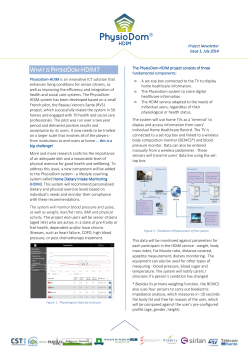

© Copyright 2026