
このたびは、当社製品をお買い上げいただきまして、誠にありがとうござ 切 います。ご使用の前に本書を必ずお読みいただくとともに常にお手元に 保管いただき、正しいお取り扱い方法でご愛用いただけますようお願い
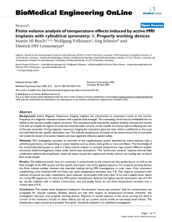
日本国内でご購入の場合は1ページから54ページをお読みください。
切
り
取
り
線
このたびは、当社製品をお買い上げいただきまして、誠にありがとうござ
います。ご使用の前に本書を必ずお読みいただくとともに常にお手元に
保管いただき、正しいお取り扱い方法でご愛用いただけますようお願い
申し上げます。なお、本品の装着に関する事故や弊害につきましては、
いかなる場合においても、当社は一切責任を負いかねますので、あらか
じめご了承いただけますようお願い申し上げます。
※英語の部分は国内では無効です。
【Webサイト】http://www.nippon-seiki.co.jp/defi/
【電話番号】
(03)3835-3639(Japanese only)
【受付時間】10:00∼12:00, 13:00∼17:00
(土・日、祭日、当社休日を除く平日)
English section is from P.55 to P.110.
Thank you very much for purchasing our product. Before installing
and using the product, please read this manual thoroughly. After
installation, please keep this manual for future reference.
※Japanese section is effective only in Japan.
【Web site】http://www.defi-shop.com/
【E-mail】[email protected]
Exciting Products by NS
Contents
1.Safety Warning ‥‥‥‥‥‥‥‥‥‥‥‥‥‥‥‥‥‥‥‥‥P56∼60
2.Main Product Features ‥‥‥‥‥‥‥‥‥‥‥‥‥‥‥‥‥P61∼64
3.The list of Defi-Link System ‥‥‥‥‥‥‥‥‥‥‥‥‥‥‥P65・66
4.Specification ‥‥‥‥‥‥‥‥‥‥‥‥‥‥‥‥‥‥‥‥‥‥‥‥‥P67
5.Product Parts ‥‥‥‥‥‥‥‥‥‥‥‥‥‥‥‥‥‥‥‥‥‥P68∼78
Optional Parts List ‥‥‥‥‥‥‥‥‥‥‥‥‥‥‥‥‥‥‥‥‥‥P78
List of tools to use ‥ ‥‥‥‥‥‥‥‥‥‥‥‥‥‥‥‥‥‥‥‥‥P79
6.How to Install
・ Installation diagram ‥‥‥‥‥‥‥‥‥‥‥‥‥‥‥‥‥‥‥‥P80
・ How to attach sensors ‥‥‥‥‥‥‥‥‥‥‥‥‥‥‥‥P81∼88
・ Wiring the Control Unit Ⅱ ‥‥‥‥‥‥‥‥‥‥‥‥‥‥‥‥‥P89
・ How to attach the Control Unit Ⅱ ‥‥‥‥‥‥‥‥‥‥‥‥‥P90
・ How to Install meters‥‥‥‥‥‥‥‥‥‥‥‥‥‥‥‥‥P91・92
・ How to attach optional parts ‥‥‥‥‥‥‥‥‥‥‥‥‥P93・94
(A) Single Meter Visor ‥‥‥‥‥‥‥‥‥‥‥‥‥‥‥‥‥‥‥P93
(B) Fitting Kit ‥‥‥‥‥‥‥‥‥‥‥‥‥‥‥‥‥‥‥‥‥‥‥P93
(C) Defi-Link Indicator‥‥‥‥‥‥‥‥‥‥‥‥‥‥‥‥‥‥‥‥P94
・ Final confirmation after Installation ‥‥‥‥‥‥‥‥‥‥‥‥P95
7.Operation
(A) Names of parts ‥‥‥‥‥‥‥‥‥‥‥‥‥‥‥‥‥‥‥‥‥‥P96
(B) Mode
「REAL MODE」
・
「PEAK MODE」‥‥‥‥‥‥‥‥‥‥‥‥‥‥P97
「WARNING SET MODE」‥‥‥‥‥‥‥‥‥‥‥‥‥‥‥‥‥‥P98
「WARNING MODE」 ‥‥‥‥‥‥‥‥‥‥‥‥‥‥‥‥‥‥‥‥P99
「RECORD MODE」
・
「PLAYBACK MODE」 ‥‥‥‥‥P100・101
「DIFFERENTIAL PRESSURE MODE」‥‥‥‥‥‥‥‥‥‥‥P102
「ILLUMINATION FUNCTION」‥‥‥‥‥‥‥‥‥‥‥‥‥‥‥P103
(C) Check Functions ‥‥‥‥‥‥‥‥‥‥‥‥‥‥‥‥‥P104・105
8.Trouble Shooting ‥‥‥‥‥‥‥‥‥‥‥‥‥‥‥‥‥‥‥P106・107
9.Terms and Conditions ‥‥‥‥‥‥‥‥‥‥‥‥‥‥‥‥P108∼110
Warranty ‥‥‥‥‥‥‥‥‥‥‥‥‥‥‥‥‥‥‥‥‥‥‥‥‥‥‥‥P111
55
Please be sure to read this manual carefully before attempting to install
or operate this product.
1.SAFETY WARNING
Please read carefully, where the "
WARNING " and
" CAUTION "symbols are displayed in this manual.
Failure to do so may result in damage or injury.
WARNING
Indicates the possibility of death or serious injury in the event of
incorrect installation.
CAUTION
Indicates a risk of personal injury or damage to equipment in the event
of incorrect installation.
CONFIRMATION:
Indicates the need to confirm that a particular task has been correctly
completed.
Please refer to our website in order to acquire the latest information.
http : //www.defi-shop.com
(A) BEFORE INSTALLATION (for installation personnel)
WARNING
●All instructions in this manual must be followed to ensure safe
installation and operation of the product.
56
●The components of the product should be installed in a place where
they can not fall or move and damage the vehicle or hinder driving.
●NEVER dismantle or re-assemble the products. This could cause
damage and make them unsafe to use. Tampering with the products
renders the limited warranty ineffective.
●Before installation, please make sure that the engine is switched off
and the vehicle is stationary.
●Due to possible injury from contact with a hot engine or exhaust pipe,
do not begin installation until the vehicle is cool.
●Prior to installation, remove the ignition key and disconnect the
negative ( - ) battery terminal.
●Please take care while installing this product so you do not interfere
with any connections or wires relating to seat belts, air bags or other
safety devices.
●Before tapping engine rev or speed signal from the ECU, please make
sure that you have connected power cables inside "DC Source"
harness properly. And then confirm that the Defi-Link Control Unit and
the Defi-Link Meters will perform opening/ending function normally. If
it is functioning normally, remove negative terminal connector from
battery and go ahead with wiring procedure. NOTE: Incorrect wiring
may destroy your ECU, Ignition system, and other engine
management devices.
●When attaching wiring, use the solderless connectors or inner/outer
connections, and insulate all connections with electrical tape. Please
insulate all connections in areas where wires will be tight.
●While wiring power harness, to avoid the risk of electrical shock or
fire, be sure to confirm that there is no disconnection or breakage of
wire. Poor connection can result in short-circuit, electrical shock, fire,
or other hazards.
●Ignition-switched +12V (IGN) line must be connected to the vehicle's
Ignition-switched wire with a fuse of 30A or less. High-capacity fuse
57
(more than 30A) will not blowout even with an abnormal current flow
and may cause fire.
CAUTION
●This product is for use ONLY on vehicles with a 12V electrical
system. NEVER use the product on 24V vehicles.
●Use only the wires provided. If additional wires are required, use the
same of quality and gauge wire as is provided with the kit.
●Insulate any unused wires. If any wires or connectors loosen during
installation, please make sure they are correctly reattached.
●Dropping any of the components of this product will result in damage
to the product.
●Excessive force on switches/terminals may result in damage to the product.
●Do not attach wires on the body of the vehicle or engine parts as this
may result in damage to the product.
●Install sensors away from heat and moisture to avoid damage.
●Do not pull away the wire.
●Install sensors away from ignition and also radio signal frequency
interference as this could cause the gauges to malfunction.
●Do not wire the sensor wires near the engine, exhaust pipe or turbine.
It may result in damage or fusion of wires.
●Do not expose control unit to moisture, dust or direct sunlight, or
place product directly in front of heat vents.
●Make sure the waterproof processing is done when diverging wires in
the engine compartment.
●Wear gloves so as not to get burnt when soldering.
●If the negative battery terminal is disconnected, audio and clock
memory data may be lost. The necessary data will have to be re-set
after installation.
58
CONFIRMATION
●Gauge pointer may not be in the proper position when you purchase.
Normal function will resume when power is connected.
●Please read pages for the customer as well as the pages for the
installation personnel in order to have a full understanding of all the
procedures.
●Please confirm with the maintenance book on the car that the
manufacturer issued when installing and detaching genuine parts.
●After installation is complete, return this operations manual to the
customer along with the warranty.
●Before tapping wires, check the voltage of the existing wire. After
tapping the wire, check the voltage of the tapped wire again to
confirm whether you have tapped into the proper place.
(B)PROPER PRODUCT HANDLING(for customer)
WARNING
●Please have this product installed by the retail store or dealer where
it was purchased. Installation by the customer will void the warranty.
●Do not disassemble or modify this product. Such actions cannot only
damage or destroy the product but will also void the warranty.
●In order to ensure safe driving, check the information on the meters
only for short period of time. Looking at the meters for long periods
of time could distract adequate attention from the road and result in
an accident.
●Discontinue use of this product if meters don’
t operate, water gets
into the unit, or smoke or a strange odor comes from the unit. If such
a condition occurs, contact the sales outlet or installation personnel
as soon as possible. Continued use while the condition exists could
result in an accident or fire.
59
CONFIRMATION
●Do not set the number of cylinders when TACHOMETER is not
installed.
*Please pull out each connector while pressing the lock of the
connector firmly.
Diameter Conversion Table
mm
inch
52
2 1/16
60
2 3/8
80
3 1/8
115
4 1/2
60
2.MAIN PRODUCT FEATURES (for customer)
Defi-Link Meter
Indicator
To Power
Source
To sensor
METER OUTPUT 1
(M-WARNING)
Control Unit Ⅱ
Defi-Link Meter BF
Indicator
61
METER OUTPUT 2
Daisy Chain Connection
a)Multiple Interface System
Uses only one wire to send power, light, ground, and data to and from all seven
gauges.
All gauges and the Control Unit Ⅱ have separate microcomputer units.
b)Easy installation
Installing additional gauges involves simply connecting them to the installed
gauge and wiring the sensor to the Control Unit Ⅱ.
c)Easy operation
Gauges that are out of reach can be controlled by using the Control Unit Ⅱ at
hand.
It is possible to connect up to seven gauges to one Control Unit Ⅱ.
Using only one switch, it is possible to display memory replay,
peak memory and warning set values for all gauges.
d)Low cost
It is not necessary to purchase additional control units when installing
additional gauges.
*Daisy Chain connection cannot be applied to connection between Defi- Link
Meter BFs and Defi-Link Meters.
Common features of Defi-Link Meter BF and Defi-Link Meter
1.Stepping Motor
a)Quick response
Gauge pointers driven by stepping motor have a smooth instantaneous
response to rapid acceleration of high performance vehicles.
b)High precision and light weight
Maximum angle of deflective, 270゜is controlled by the microcomputer up to
2,300 times(0.12゜
) to provide high precision in the accuracy of information
generated.
Compared to similar products from other companies, this product is
30% lighter.
c) Freedom of installation
There is no“dumping of oil”
. The meter can be installed at any angle.
2.Multiple functions
a)When the ignition is turned on, "opening mode" automatically begins.
When the engine is started, all LED indicators light and all gauge pointers move.
The gauges perform a self-test.
62
b)Wiring check function
Any cut wire, short circuit, and communication errors are checked and
possible areas of fault are checked.
c)Warning function
A warning value can be set. When this value is exceeded, a red warning LED
comes on.
It is possible to connect a Defi-Link Indicator(sold separately).
d)Peak memory function
Peak values are stored and can be checked later.
3.Attractive design
a)A mounting bracket and instrument case is provided with the product.
Defi-Link gauge installation stand(Meter holder) is included with all products.
The back of each gauge is made of an attractive black case.
b)Bezel
The Bezel is hairline finish with an alumite processing which gives it a high
gloss look.
c)LED Lamps
The lights are produced from high intensity LED lamps.
Features of Defi-Link Meter BF
a)1.LED illumination
Gauge dials are invisible while the ignition switch is off. Once the ignition
switch is turned on, a clear display appears by colored LED illumination.
2.Red emitting needle pointer
Gauge dial illumination and a red emitting needle pointer increase visibility.
b)1."Opening mode"
Illumination of gauge dial, needle pointer, and each LED are turned on being
interlocked with ignition switch on. After the illumination is turned on, it goes
out once and then comes back on again.
2."Closing mode"
Illumination of gauge dial, warning LED, peak LED, and needle pointer all
gradually goes out after the ignition switch is turned off.
c)1.Brightness can be adjusted. There are 5 stages of brightness in the daytime
and 5 stages in the nighttime. The brightness decreases being interlocked
with the illumination switch on.
The decrease in lights can be canceled.
63
Features of Defi-Link Meter
a)A bright transparent green gauge dial and a red instrument needle pointer are
used in the gauges to increase visibility at night and in low-light applications.
Features of Defi-Link Control Unit Ⅱ
a)Up to 7 gauges from among Defi-Link Meter BFs and Defi-Link Meters can be
operated with one Control Unit Ⅱ. Microcomputers are equipped with meters
and Control Unit Ⅱ. A distant meter can be operated at hand. Daisy Chain
Connection can not be applied to connect Defi-Link Meter BFs and Defi-Link
Meters.
b)Driving data can be stored in each meter up to 3 minutes and can be replayed.
Pause, speed play, forward, and rewind function can be applied during playback.
c)The switch panel is embossed. When the switch is pushed, the buzzer sounds
and the positive feelings of desired operation are obtained.
d)The characters and the rings on the switch panel are illuminated in white at
nighttime. It makes operation in the dark easy.
e)As a warning function, red warning LEDs of meters come on and a buzzer
sounds at the same time.
f)Defi-Link Indicator Ⅱ or Defi-Link Indicator can be used as a Master Warning by
connecting it to M-WARNIG connector of Control Unit Ⅱ.
The Indicator lights up when any of warning LEDs of connected meters go on
except tachometer.
(Tachometer warning is included in Master Warning of DF05001.)
g)If both the fuel pressure meter and turbo meter are installed, the fuel pressure
meter shows the differential pressure between fuel pressure and turbo.
64
3.The list of Defi-Link System
Defi-Link Meter BF
Size
60mm
Product Name
Illumination
Color
White
TURBO
Amber Red
White
OIL PRESS.
Amber Red
White
FUEL PRESS.
Amber Red
White
OIL TEMP.
Amber Red
White
WATER TEMP.
Amber Red
White
EXHAUST TEMP.
Amber Red
INTAKE MANIFOLD White
PRESS.
Amber Red
Part
Number
Illumination
Color
Part
Number
DF04301
DF04302
DF04401
DF04402
DF04501
DF04502
DF04601
DF04602
DF04701
DF04702
DF04801
DF04802
DF04901
DF04902
Blue
DF04305
Blue
DF04405
Blue
DF04505
Blue
DF04605
Blue
DF04705
Blue
DF04805
Blue
DF04905
Gross
Weight(g)
450
460
460
425
425
495
450
Defi-Link Meter
Size
Product Name
Dial Face
Color
Part
Number
White
Black
White
Black
White
Black
White
Black
White
Black
White
Black
White
Black
White
Black
DF00605
DF00606
DF00705
DF00706
DF00805
DF00806
DF00905
DF00906
DF01005
DF01006
DF01105
DF01106
DF01205
DF01206
DF05401
DF05402
Defi-Link Meter TURBO
Defi-Link Meter OIL PRESS.
Defi-Link Meter FUEL PRESS.
Defi-Link Meter OIL TEMP.
60mm
Defi-Link Meter WATER TEMP.
Defi-Link Meter EXHAUST TEMP.
Defi-Link Meter TACHOMETER
Defi-Link Meter
INTAKE MANIFOLD PRESS.
◆Diameter Conversion Table (Refer to P.60.)
65
Gross
Weight(g)
470
480
480
440
440
480
435
470
100g=0.2lb
Defi-Link Meter
Size
Product Name
Defi-Link Meter TURBO
Defi-Link Meter OIL PRESS.
Defi-Link Meter FUEL PRESS.
52mm
Defi-Link Meter OIL TEMP.
Defi-Link Meter WATER TEMP.
Defi-Link Meter EXHAUST TEMP.
Defi-Link Meter
INTAKE MANIFOLD PRESS.
Defi-Link Meter TURBO
80mm
Defi-Link Meter
TACHOMETER
9,000RPM
11,000RPM
Defi-Link Meter TURBO
115mm
Defi-Link Meter
TACHOMETER
11,000RPM
Dial Face
Color
Part
Number
White
Black
White
Black
White
Black
White
Black
White
Black
White
Black
White
Black
White
Black
White
Black
White
Black
White
Black
White
Black
DF01905
DF01906
DF02005
DF02006
DF02105
DF02106
DF02205
DF02206
DF02305
DF02306
DF02405
DF02406
DF05501
DF05502
DF06101
DF06102
DF03405
DF03406
DF03407
DF03408
DF02803
DF02804
DF02905
DF02906
Gross
Weight(g)
455
465
465
425
425
465
455
520
480
845
780
Defi-Link
Size
60mm
52, 60, 80mm
Product Name
Defi-Link
Defi-Link
Defi-Link
Defi-Link
Defi-Link
Control Unit Ⅱ
Indicator
Indicator Ⅱ
Single Meter Visor
Fitting Kit
66
Part
Number
Gross
Weight(g)
DF05002
DF01801
DF05801
DF05201
DF05301
390
40
150
70
40
4.Specification
Power Supply Voltage
DC10V∼15V(For 12V vehicles)
Current Consumption
(Maximum value in case 7 gauges are connected to the Defi-Link Control Unit Ⅱ
+B line MAX 2A (Dark current MAX 2.5mA)
IGN line MAX 0.1A
ILM line MAX 0.2A
Operational Temperature Range
-20 ∼ +60℃, -4 ∼ +140°
F (under 80% relative humidity)
Storage Temperature Range
-40 ∼ +80℃, -40 ∼ +176°
F (under 80% relative humidity)
Display Range
Turbo
-100kPa ∼ +200kPa
Intake Manifold Press.
-100kPa ∼ +20kPa
Oil Press.
0 ∼ 1,000kPa
Fuel Press.
0 ∼ 600kPa
Oil Temp.
50 ∼ 150℃
Water Temp.
20 ∼ 120℃
Exhaust Temp.
200 ∼ 1,100℃
Tachometer
φ60, φ80
0 ∼ 9,000 RPM
φ80, φ115
0 ∼ 11,000 RPM
Applicable Number of Cylinders
1・2・3・4・5・6・8
*Applicable numbers of cylindes of DF05001 are 3, 4, 5, 6 and 8.
Installation of φ60 Bezel, hood, and visor
●Triple Meter Hood and Bezel
DF033A0
DF033DC
DF03301
DF03302
DF03303
×
Attachable
×
×
Attachable
●DF05201 Single Meter Visor cannot be attached with the bezel.
67
*Each part can be purchased
separately. Please contact us.
5.PRODUCT PARTS
TURBO
(52mm & 60mm & 80mm)
INTAKE MANIFOLD PRESS.
(52mm & 60mm)
White
3pins
Gauge 1pc
Boost sensor
2.5m(8 1/5ft.)1pc
Rubber hose 0.5m
(1 3/5ft.) 1pc
Three way joint 1pc
日本国 内でご 購入の 場合は 1ペー ジから 54ペ ージを お読み くださ い。
このたびは、当社製品をお買い上げいただきまして、誠にありがとうござ
います。 ご使用 の前に 本書を 必ずお 読みい ただく ととも に常に お手元 に
保管い ただき 、正し いお取 り扱い 方法で ご愛用 いただ けます ようお 願い
申し 上げ ます 。な お、 本品 の装 着に 関す る事 故や 弊害 につ きま して は、
いかな る場合 におい ても、 当社は 一切責 任を負 いかね ますの で、あ らか
じめご了承いただけますようお願い申し上げます。
※英語の部分は国内では無効です。
【Webサイト】http://www.nippon-seiki.co.jp/defi/
【Eメール】[email protected]
【電話番号】
(03)3835-3639(Japanese only)
【受付時間】10:00∼12:00, 13:00∼17:00
(土・日、祭日、当社休日を除く平日)
English section is from P.55 to P.110.
Thank you very much for purchasing our product. Before installing
and using the product, please read this manual thoroughly. After
installation, please keep this manual for future reference.
※Japanese section is effective only in Japan.
【Web site】http://www.defi-shop.com/
【E-mail】[email protected]
Exciting Products by NS
Meter wire 0.25m
(10") 1pc
Operation manual 1pc
Meter cup 1pc
Meter cup holder
Double sided
tape 1pc
Buffer 1pc
Mounting
bracket 1pc
*A bezel is a standard equipment for
φ52 and φ60 Defi-Link Meter.
*Some kinds of meter hoods and visor
cannot be installed in combination
with the bezel. (Refer to P.67)
68
M4 bolt, nut
washer 1pc
*Each part can be purchased
separately. Please contact us.
TURBO(115mm)
White
3pins
Gauge 1pc
Boost sensor 2.5m
(8 1/5ft.)1pc
Meter wire 0.25m (10") 1pc
Three way joint 1pc
Rubber hose 0.5m
(1 3/5ft.) 1pc
Meter cup 1pc
日本国 内でご 購入の 場合は 1ペー ジから 54ペ ージを お読み くださ い。
このたびは、当社製品をお買い上げいただきまして、誠にありがとうござ
います。 ご使用 の前に 本書を 必ずお 読みい ただく ととも に常に お手元 に
保管い ただき 、正し いお取 り扱い 方法で ご愛用 いただ けます ようお 願い
申し 上げ ます 。な お、 本品 の装 着に 関す る事 故や 弊害 につ きま して は、
いかな る場合 におい ても、 当社は 一切責 任を負 いかね ますの で、あ らか
じめご了承いただけますようお願い申し上げます。
※英語の部分は国内では無効です。
【Webサイト】http://www.nippon-seiki.co.jp/defi/
【Eメール】[email protected]
【電話番号】
(03)3835-3639(Japanese only)
【受付時間】10:00∼12:00, 13:00∼17:00
(土・日、祭日、当社休日を除く平日)
English section is from P.55 to P.110.
Thank you very much for purchasing our product. Before installing
and using the product, please read this manual thoroughly. After
installation, please keep this manual for future reference.
※Japanese section is effective only in Japan.
【Web site】http://www.defi-shop.com/
【E-mail】[email protected]
Exciting Products by NS
Bolt for Meter cup 1pc
Operation manual 1pc
Accessories for 115mm gauge
Mounting
bracket 1pc
Tapping screw 2pcs
Double sided tape 2pcs
M6 bolt, nut 1pc,
washer 2pcs
69
Buffer 4pcs
Solderless
connector 1pc
*Each part can be purchased
separately. Please contact us.
OIL PRESS.(52mm & 60mm)
* After the oil pressure sensor
is connected, a buzzer
sounds when the ignition
switch is turned on but the
engine is not started.
Gauge 1pc
* Pressure sensor 1pc
Meter wire 0.25m (10") 1pc
Meter cup 1pc
Black
3pins
日本国 内でご 購入の 場合は 1ペー ジから 54ペ ージを お読み くださ い。
このたびは、当社製品をお買い上げいただきまして、誠にありがとうござ
います。 ご使用 の前に 本書を 必ずお 読みい ただく ととも に常に お手元 に
保管い ただき 、正し いお取 り扱い 方法で ご愛用 いただ けます ようお 願い
申し 上げ ます 。な お、 本品 の装 着に 関す る事 故や 弊害 につ きま して は、
いかな る場合 におい ても、 当社は 一切責 任を負 いかね ますの で、あ らか
じめご了承いただけますようお願い申し上げます。
※英語の部分は国内では無効です。
【Webサイト】http://www.nippon-seiki.co.jp/defi/
【Eメール】[email protected]
【電話番号】
(03)3835-3639(Japanese only)
【受付時間】10:00∼12:00, 13:00∼17:00
(土・日、祭日、当社休日を除く平日)
English section is from P.55 to P.110.
Thank you very much for purchasing our product. Before installing
and using the product, please read this manual thoroughly. After
installation, please keep this manual for future reference.
※Japanese section is effective only in Japan.
【Web site】http://www.defi-shop.com/
【E-mail】[email protected]
Exciting Products by NS
Sensor wire 2.5m (8 1/5ft.) 1pc
Operation manual 1pc
Meter cup holder
Double sided
tape 1pc
Buffer 1pc
Mounting
bracket 1pc
*A bezel is a standard equipment for
φ52 and φ60 Defi-Link Meter.
*Some kinds of meter hoods and visor
cannot be installed in combination
with the bezel. (Refer to P.67)
70
M4 bolt, nut
washer 1pc
*Each part can be purchased
separately. Please contact us.
FUEL PRESS.(52mm & 60mm)
Pressure sensor 1pc
Gauge 1pc
Meter wire 0.25m (10") 1pc
Meter cup 1pc
Blue
3pins
日本国 内でご 購入の 場合は 1ペー ジから 54ペ ージを お読み くださ い。
このたびは、当社製品をお買い上げいただきまして、誠にありがとうござ
います。 ご使用 の前に 本書を 必ずお 読みい ただく ととも に常に お手元 に
保管い ただき 、正し いお取 り扱い 方法で ご愛用 いただ けます ようお 願い
申し 上げ ます 。な お、 本品 の装 着に 関す る事 故や 弊害 につ きま して は、
いかな る場合 におい ても、 当社は 一切責 任を負 いかね ますの で、あ らか
じめご了承いただけますようお願い申し上げます。
※英語の部分は国内では無効です。
【Webサイト】http://www.nippon-seiki.co.jp/defi/
【Eメール】[email protected]
【電話番号】
(03)3835-3639(Japanese only)
【受付時間】10:00∼12:00, 13:00∼17:00
(土・日、祭日、当社休日を除く平日)
English section is from P.55 to P.110.
Thank you very much for purchasing our product. Before installing
and using the product, please read this manual thoroughly. After
installation, please keep this manual for future reference.
※Japanese section is effective only in Japan.
【Web site】http://www.defi-shop.com/
【E-mail】[email protected]
Exciting Products by NS
Sensor wire 2.5m (8 1/5ft.) 1pc
Operation manual 1pc
Meter cup holder
Double sided
tape 1pc
Buffer 1pc
Mounting
bracket 1pc
*A bezel is a standard equipment for
φ52 and φ60 Defi-Link Meter.
*Some kinds of meter hoods and visor
cannot be installed in combination
with the bezel. (Refer to P.67)
71
M4 bolt, nut
washer 1pc
*Each part can be purchased
separately. Please contact us.
OIL TEMP.(52mm & 60mm)
Gauge 1pc
Temperature sensor 1pc
Meter wire 0.25m (10") 1pc
Meter cup 1pc
White
2pins
日本国 内でご 購入の 場合は 1ペー ジから 54ペ ージを お読み くださ い。
このたびは、当社製品をお買い上げいただきまして、誠にありがとうござ
います。 ご使用 の前に 本書を 必ずお 読みい ただく ととも に常に お手元 に
保管い ただき 、正し いお取 り扱い 方法で ご愛用 いただ けます ようお 願い
申し 上げ ます 。な お、 本品 の装 着に 関す る事 故や 弊害 につ きま して は、
いかな る場合 におい ても、 当社は 一切責 任を負 いかね ますの で、あ らか
じめご了承いただけますようお願い申し上げます。
※英語の部分は国内では無効です。
【Webサイト】http://www.nippon-seiki.co.jp/defi/
【Eメール】[email protected]
【電話番号】
(03)3835-3639(Japanese only)
【受付時間】10:00∼12:00, 13:00∼17:00
(土・日、祭日、当社休日を除く平日)
English section is from P.55 to P.110.
Thank you very much for purchasing our product. Before installing
and using the product, please read this manual thoroughly. After
installation, please keep this manual for future reference.
※Japanese section is effective only in Japan.
【Web site】http://www.defi-shop.com/
【E-mail】[email protected]
Exciting Products by NS
Sensor wire 2.5m (8 1/5ft.) 1pc
Operation manual 1pc
Meter cup holder
Double sided
tape 1pc
Buffer 1pc
Mounting
bracket 1pc
*A bezel is a standard equipment for
φ52 and φ60 Defi-Link Meter.
*Some kinds of meter hoods and visor
cannot be installed in combination
with the bezel. (Refer to P.67)
72
M4 bolt, nut
washer 1pc
*Each part can be purchased
separately. Please contact us.
WATER TEMP.(52mm & 60mm)
Gauge 1pc
Temperature sensor 1pc
Meter cup 1pc
Meter wire 0.25m (10") 1pc
Blue
2pins
日本国 内でご 購入の 場合は 1ペー ジから 54ペ ージを お読み くださ い。
このたびは、当社製品をお買い上げいただきまして、誠にありがとうござ
います。 ご使用 の前に 本書を 必ずお 読みい ただく ととも に常に お手元 に
保管い ただき 、正し いお取 り扱い 方法で ご愛用 いただ けます ようお 願い
申し 上げ ます 。な お、 本品 の装 着に 関す る事 故や 弊害 につ きま して は、
いかな る場合 におい ても、 当社は 一切責 任を負 いかね ますの で、あ らか
じめご了承いただけますようお願い申し上げます。
※英語の部分は国内では無効です。
【Webサイト】http://www.nippon-seiki.co.jp/defi/
【Eメール】[email protected]
【電話番号】
(03)3835-3639(Japanese only)
【受付時間】10:00∼12:00, 13:00∼17:00
(土・日、祭日、当社休日を除く平日)
English section is from P.55 to P.110.
Thank you very much for purchasing our product. Before installing
and using the product, please read this manual thoroughly. After
installation, please keep this manual for future reference.
※Japanese section is effective only in Japan.
【Web site】http://www.defi-shop.com/
【E-mail】[email protected]
Exciting Products by NS
Sensor wire 2.5m (8 1/5ft.) 1pc
Operation manual 1pc
Meter cup holder
Double sided
tape 1pc
Buffer 1pc
Mounting
bracket 1pc
*A bezel is a standard equipment for
φ52 and φ60 Defi-Link Meter.
*Some kinds of meter hoods and visor
cannot be installed in combination
with the bezel. (Refer to P.67)
73
M4 bolt, nut
washer 1pc
*Each part can be purchased
separately. Please contact us.
EXHAUST TEMP.(52mm & 60mm)
Gauge 1pc
Exhaust temperature sensor 1pc
Black
2pins
Meter wire 0.25m (10") 1pc
Sensor wire 2.5m (8 1/5ft.) 1pc
Meter cup 1pc
日本国 内でご 購入の 場合は 1ペー ジから 54ペ ージを お読み くださ い。
このたびは、当社製品をお買い上げいただきまして、誠にありがとうござ
います。 ご使用 の前に 本書を 必ずお 読みい ただく ととも に常に お手元 に
保管い ただき 、正し いお取 り扱い 方法で ご愛用 いただ けます ようお 願い
申し 上げ ます 。な お、 本品 の装 着に 関す る事 故や 弊害 につ きま して は、
いかな る場合 におい ても、 当社は 一切責 任を負 いかね ますの で、あ らか
じめご了承いただけますようお願い申し上げます。
※英語の部分は国内では無効です。
【Webサイト】http://www.nippon-seiki.co.jp/defi/
【Eメール】[email protected]
【電話番号】
(03)3835-3639(Japanese only)
【受付時間】10:00∼12:00, 13:00∼17:00
(土・日、祭日、当社休日を除く平日)
English section is from P.55 to P.110.
Thank you very much for purchasing our product. Before installing
and using the product, please read this manual thoroughly. After
installation, please keep this manual for future reference.
※Japanese section is effective only in Japan.
【Web site】http://www.defi-shop.com/
【E-mail】[email protected]
Exciting Products by NS
Fitting(1/8PT) 1pc
Operation manual 1pc
Meter cup holder
Double sided
tape 1pc
Buffer 1pc
Mounting
bracket 1pc
*A bezel is a standard equipment for
φ52 and φ60 Defi-Link Meter.
*Some kinds of meter hoods and visor
cannot be installed in combination
with the bezel. (Refer to P.67)
74
M4 bolt, nut
washer 1pc
*Each part can be purchased
separately. Please contact us.
TACHOMETER(60mm)
Gauge 1pc
Meter wire 0.25m (10") 1pc
White
2pins
Meter cup 1pc
日本国 内でご 購入の 場合は 1ペー ジから 54ペ ージを お読み くださ い。
このたびは、当社製品をお買い上げいただきまして、誠にありがとうござ
います。 ご使用 の前に 本書を 必ずお 読みい ただく ととも に常に お手元 に
保管い ただき 、正し いお取 り扱い 方法で ご愛用 いただ けます ようお 願い
申し 上げ ます 。な お、 本品 の装 着に 関す る事 故や 弊害 につ きま して は、
いかな る場合 におい ても、 当社は 一切責 任を負 いかね ますの で、あ らか
じめご了承いただけますようお願い申し上げます。
※英語の部分は国内では無効です。
【Webサイト】http://www.nippon-seiki.co.jp/defi/
【Eメール】[email protected]
【電話番号】
(03)3835-3639(Japanese only)
【受付時間】10:00∼12:00, 13:00∼17:00
(土・日、祭日、当社休日を除く平日)
English section is from P.55 to P.110.
Thank you very much for purchasing our product. Before installing
and using the product, please read this manual thoroughly. After
installation, please keep this manual for future reference.
※Japanese section is effective only in Japan.
【Web site】http://www.defi-shop.com/
【E-mail】[email protected]
Exciting Products by NS
Signal wire 2m (6 3/5ft.) 1pc
Operation manual 1pc
Solderless
connector 1pc
Meter cup holder
Double sided
tape 1pc
Buffer 1pc
Mounting
bracket 1pc
*A bezel is a standard equipment for
φ52 and φ60 Defi-Link Meter.
*Some kinds of meter hoods and visor
cannot be installed in combination
with the bezel. (Refer to P.67)
75
M4 bolt, nut
washer 1pc
*Each part can be purchased
separately. Please contact us.
TACHOMETER(80mm)
Gauge 1pc
Meter wire 0.25m (10") 1pc
Meter cup 1pc
White
2pins
Signal wire 2m (6 3/5ft.) 1pc
日本国 内でご 購入の 場合は 1ペー ジから 54ペ ージを お読み くださ い。
このたびは、当社製品をお買い上げいただきまして、誠にありがとうござ
います。 ご使用 の前に 本書を 必ずお 読みい ただく ととも に常に お手元 に
保管い ただき 、正し いお取 り扱い 方法で ご愛用 いただ けます ようお 願い
申し 上げ ます 。な お、 本品 の装 着に 関す る事 故や 弊害 につ きま して は、
いかな る場合 におい ても、 当社は 一切責 任を負 いかね ますの で、あ らか
じめご了承いただけますようお願い申し上げます。
※英語の部分は国内では無効です。
【Webサイト】http://www.nippon-seiki.co.jp/defi/
【Eメール】[email protected]
【電話番号】
(03)3835-3639(Japanese only)
【受付時間】10:00∼12:00, 13:00∼17:00
(土・日、祭日、当社休日を除く平日)
English section is from P.55 to P.110.
Thank you very much for purchasing our product. Before installing
and using the product, please read this manual thoroughly. After
installation, please keep this manual for future reference.
※Japanese section is effective only in Japan.
【Web site】http://www.defi-shop.com/
【E-mail】[email protected]
Exciting Products by NS
Operation manual 1pc
Solderless
connector 1pc
Meter cup holder
Double sided
tape 1pc
Buffer 1pc
Mounting
bracket 1pc
M4 bolt, nut
washer 1pc
*4 types of 80mm tachometers are available. 9,000RPM(White)
11,000RPM(White) 9,000RPM(Black) 11,000RPM(Black)
76
*Each part can be purchased
separately. Please contact us.
TACHOMETER(115mm)
Gauge 1pc
Meter wire 0.25m (10") 1pc
White
2pins
Meter cup 1pc
Signal wire 2m (6 3/5ft.) 1pc
日本国 内でご 購入の 場合は 1ペー ジから 54ペ ージを お読み くださ い。
このたびは、当社製品をお買い上げいただきまして、誠にありがとうござ
います。 ご使用 の前に 本書を 必ずお 読みい ただく ととも に常に お手元 に
保管い ただき 、正し いお取 り扱い 方法で ご愛用 いただ けます ようお 願い
申し 上げ ます 。な お、 本品 の装 着に 関す る事 故や 弊害 につ きま して は、
いかな る場合 におい ても、 当社は 一切責 任を負 いかね ますの で、あ らか
じめご了承いただけますようお願い申し上げます。
※英語の部分は国内では無効です。
【Webサイト】http://www.nippon-seiki.co.jp/defi/
【Eメール】[email protected]
【電話番号】
(03)3835-3639(Japanese only)
【受付時間】10:00∼12:00, 13:00∼17:00
(土・日、祭日、当社休日を除く平日)
English section is from P.55 to P.110.
Thank you very much for purchasing our product. Before installing
and using the product, please read this manual thoroughly. After
installation, please keep this manual for future reference.
※Japanese section is effective only in Japan.
【Web site】http://www.defi-shop.com/
【E-mail】[email protected]
Exciting Products by NS
Bolt for Meter cup 1pc
Operation manual 1pc
Accessories for 115mm gauge
Mounting
bracket 1pc
Double sided tape 2pcs
Tapping screw 2pcs
M6 bolt, nut 1pc,
washer 2pcs
77
Buffer 4pcs
Solderless
connector 1pc
*Each part can be purchased
separately. Please contact us.
Defi-Link Control Unit Ⅱ(52, 60, 80, 115mm)
Control Unit Ⅱ 1pc
Power wire 0.75m
(2 1/2ft.) 1pc
Meter wire 2m(6 3/5ft.) 1pc
Parts for the control unit
日本国 内でご 購入の 場合は 1ペー ジから 54ペ ージを お読み くださ い。
このたびは、当社製品をお買い上げいただきまして、誠にありがとうござ
います。 ご使用 の前に 本書を 必ずお 読みい ただく ととも に常に お手元 に
保管い ただき 、正し いお取 り扱い 方法で ご愛用 いただ けます ようお 願い
申し 上げ ます 。な お、 本品 の装 着に 関す る事 故や 弊害 につ きま して は、
いかな る場合 におい ても、 当社は 一切責 任を負 いかね ますの で、あ らか
じめご了承いただけますようお願い申し上げます。
※英語の部分は国内では無効です。
【Webサイト】http://www.nippon-seiki.co.jp/defi/
【Eメール】[email protected]
【電話番号】
(03)3835-3639(Japanese only)
【受付時間】10:00∼12:00, 13:00∼17:00
(土・日、祭日、当社休日を除く平日)
English section is from P.55 to P.110.
Thank you very much for purchasing our product. Before installing
and using the product, please read this manual thoroughly. After
installation, please keep this manual for future reference.
※Japanese section is effective only in Japan.
【Web site】http://www.defi-shop.com/
【E-mail】[email protected]
Exciting Products by NS
Operation manual
1pc
Double sided tape 1pc
Tie wrap 2pcs
Solderless
connector 4pcs
Clip 1pc
OPTIONAL PARTS LIST
PART NAME
OIL/WATER TEMP. sensor (1/8NPT)
OIL/FUEL PRESS. sensor extension wire 1m (3 1/3ft.)
OIL/FUEL PRESS. sensor extension wire 2m (6 3/5ft.)
OIL/WATER TEMP. sensor extension wire 1m (3 1/3ft.)
OIL/WATER TEMP. sensor extension wire 2m (6 3/5ft.)
EXHAUST TEMP. sensor extension wire 2m (6 3/5ft.)
Meter wire 0.5m (1 3/5ft.)
Meter wire 1m (3 1/3ft.)
Meter wire 2m (6 3/5ft.)
Rubber boot
1/8 NPT fitting for EXHAUST TEMP. sensor
1/8NPT/PT Conversion Socket (for PRESS. sensor)
Huse (4A) 2pcs
PART NUMBER
PDF03905S
PDF06013H
PDF00707H
PDF06014H
PDF00906H
PDF01107H
PDF00614H
PDF00615H
PDF01303H
PDF01908G
PDF01109G
PDF00708G
PDF05005G
1/8NPT
Rubber boot
78
1/8PT
Conversion Socket
LIST OF TOOLS TO USE
TOOL
10mm spanner
or wrench
12mm spanner
or wrench
14mm spanner
or wrench
17mm spanner
or wrench
20mm spanner
or wrench
52, 60, 80mm
hexagonal wrench
115mm hexagonal
wrench
Tester
Extension wire
Plyers
Wiring cutters/
Side cutters
Phillips & Flat Blade Screw
Driver
1/8 drill NPT tap
Solder and solder iron
Clipped end wiring
Vinyl tape
T-Bolt clamps
Teflon tape
8.3mm drill
Cloth, cleaning liquid,water
1
2
3
4
5
6
7
1
2
○
○
○
○
○
○
○
○
○
3
4
5
○
○
6
7
○
○
○
○
○
○
○
○
○
○
○
○
○
○
○
○
○
○
○
○
○
○
○
○
○
○
○
○
○
○
○
○
○
○
○
○
○
○
○
○
○
○
○
○
○
○
○
○
○
○
○
○
○
○
○
○
○
○
○
○
○
○
○
○
○
○
○
○
○
○
○
○
○
○
○
○
○
○
○
○
○
TURBO/INTAKE MANIFOLD PRESS.
OIL TEMP.
WATER TEMP.
TACHOMETER
OIL PRESS.
FUEL PRESS.
EXHAUST TEMP.
79
6.HOW TO INSTALL(for installation personnel)
● INSTALLATION DIAGRAM(for installation personnel)
Installation diagram
Power supply wire
Huse 4A
Red : Battery
(To 12V battery wire)
Orange : IGN
(To 12V wire when
ignition on)
white color
black color
orange color
red color
unused
Defi-Link
Meter
Defi-Link
Meter BF
White : Illumination
(To 12V wire when small
lamp is on)
Black : GND
(To ground, negative
battery terminal)
orange color
white color
black color
yellow color
Control Unit Ⅱ
Sensor wire connections
position
M-WARNING
(white)
TACHOMETER (white)
WATER TEMP. (blue)
EXHAUST TEMP.(black)
OIL TEMP.
Meter wire
(white)
FUEL PRESS. (blue)
OIL PRESS.
(black)
Meter
TURBO(BOOST)/
INTAKE MANIFOLD PRESS.(white)
DC SOURCE
(white)
Meter holder
METER OUTPUT1(white)
METER OUTPUT2(white*)
yellow color
black color
white color
orange color
Control Unit Ⅱ(rear view)
*DF05001: black
WARNING
●Please read the safety warnings thoroughly for the installation and handling. Improper
installation or operation could cause the product to fall and damage the vehicle.
CAUTION
●Insert the wire that matches the wire connections position indicated on the side of
the control unit.
The unit will not function with incorrect connections.
●Pull out each connector with pressing the lock of the connector firmly.
●Put the connector of INTAKE MANIFOLD PRESS’s sensor wire in TURBO
connector(white) of Control Unit Ⅱ.
80
● HOW TO ATTACH SENSORS(for installation personnel)
TURBO
Attach with
clamps.
(commercially
available)
INTAKE MANIFOLD PRESS.
(a)
(c)
Three-way
joint
Surge tank
(b)
Fuel regulator
Rubber hose
Sensor
*Be sure to be installed being
faced the air hole down.
→To Control Unit Ⅱ
Sensor wire
1. The rubber hose attached to the sensor should be as short as possible.
Attach it with bolts (M6) in the engine compartment in an area where it
will not be subject to excess heat or vibration.
2. Access to the air pressure intake may be obtained between the surge
tank and the fuel regulator
(A)Detach the vacuum hose from the surge tank side that has loss
pressure oscillations, and connect it to the three way connector at
point(b)or(a).
(B)In order to connect the surge tank with three way connector, cut the
required length of hose from the included rubber hose.
(C)Use the remaining rubber hose to connect the sensor to the three way
connector.
WARNING
●To avoid disconnection of rubber hoses during pipe installation, use tie-wraps to
secure to adjacent hoses in the engine compartment.
CONFIRMATION
●The length of the included rubber hose is 0.5m (1 3/5ft.) Please adjust appropriately.
●The sensor must be installed being faced to the connector to the rubber hose down.
●For vehicles which have a solenoid valve between the surge tank and the fuel
pressure regulator, place a three-way joint before the solenoid.
81
OIL PRESS.
Use a commercial sensor attachment
Detach the original
element
Wind Teflon tape.
Engine
Be sure not to
twist.
Sensor attachment
(commercially available)
Thread size 1/8PT
O ring
→ To sensor wire
Sensor
Engine
WARNING
●To avoid oil leaks during installation of the sensors, use Teflon tape. Before driving,
inspect tubing and oil blocks for leaks. Leaks could cause a fire or damage the
engine.
●Oil spills by the installation work. Please replenish the engine with oil. The engine
might overheat when oil is too little.
●To avoid the damage of sensor wire, please fix the waterproof connector on the
vehicle body.
●Do not attach the pressure sensor to the place where the genuine pressure switch
is attached in the case it is attached to the oil pump body of the vehicle. The
pressure sensor might be broken and the engine oil might leak.
CONFIRMATION
●Be sure the sensor wire is not twisted when installing the sensor. The sensor wire
will be cut.
●The thread size of the pressure sensor is 1/8PT. If the thread size of the sensor
attachment for the pressure sensor is 1/8NPT, you will need the 1/8NPT / PT
conversion socket(optional part). If it is neither 1/8PT nor 1/8NPT, you will need
to purchase a conversion adapter available from hardware stores.
●Tighten the sensor into the sensor attachment and then connect it to the sensor
wire.
82
OIL TEMP.
Use a commercial sensor attachment
Detach the original
element
Engine
Wind Teflon tape.
Sensor attachment
(commercially available)
Be sure not to
twist.
Sensor
O ring
→ To sensor wire
Thread size 1/8PT
Engine
WARNING
●To avoid oil leaks during installation of the sensors, use Teflon tape. Before driving,
inspect tubing and oil blocks for leaks. Leaks could cause a fire or damage the engine.
●Oil spills by the installation work. Please replenish the engine with oil. The engine
might overheat when oil is too little.
●To avoid the damage of sensor wire, please fix the waterproof connector on the vehicle body.
CONFIRMATION
●Be sure the sensor wire is not twisted when installing the sensor. The sensor wire will be cut.
●The thread size of the temperature sensor is 1/8PT. If the thread size of the sensor
attachment for the temperature sensor is 1/8NPT, you will need the 1/8NPT
temperature sensor (optional part).
●Tighten the sensor into the sensor attachment and then connect it to the sensor wire.
83
WATER TEMP.
Use a commercial sensor attachment
Radiator
Upper hose
Sensor attachment
(commercially available)
Attach tightly with clamps.
(commercially available)
Thread size 1/8PT
Wind Teflon tape.
Sensor
*Cut the upper hose and connect
the sensor attachment between
hoses.
Be sure not to twist.
To sensor wire←
WARNING
●To avoid water leaks during installation of the sensors, use teflon tape. Attach the
T-joint and upper hose with a T-Bolt clamp. Inspect hose connections for leaks
before driving.
●Coolant spills by the installation work. Please replenish the engine with coolant
and bleed the air from the system, or the engine might overheat.
●To avoid the damage of sensor wire, please fix the waterproof connector on the
vehicle body.
CONFIRMATION
●Be sure the sensor wire is not twisted when installing the sensor. The sensor wire
will be cut.
●The thread size of the temperature sensor is 1/8PT. If the thread size of the sensor
attachment for the temperature sensor is 1/8NPT, you will need the 1/8NPT
temperature sensor (optional part).
●Tighten the sensor into the sensor attachment and then connect it to the sensor wire.
84
FUEL PRESS.
Use a commercial three-way joint and hose unions
Fuel pressure regulator
Wind Teflon tape.
To sensor wire
↑
Hose union
(commercially available)
Three-way joint
(commercially available)
Fix tightly with
clamps.
(commercially
available)
Be sure not to
twist.
Sensor
*Cut the fuel feed pipe and
install hose unions.
Thread size 1/8PT
Fuel return pipe
(low pressure)
Fuel feed pipe(high pressure)
WARNING
●To avoid fuel leaks during installation of the sensors, use Teflon tape. Attach hose
connection and fuel feed tubing with a T-Bolt clamp. Inspect pipes and hose
connections for leaks before driving.
●Before cutting the fuel feed pipe, be certain to remove the gas cap to relieve any
pressure built up in the fuel tank.
●When cutting the fuel feed pipe, be certain to discharge static electricity.
Otherwise, there is a possibility of the ignition in gasoline.
●To avoid the damage of sensor wire, please fix the waterproof connector on the
vehicle body.
CONFIRMATION
●Be sure the sensor wire is not twisted when installing the sensor. The sensor wire will be cut.
●The sensor must be installed on the feed(high pressure)pipe side between the
fuel tank and the fuel pressure regulator.
*It is not possible to obtain accurate fuel pressure from the return(low pressure)
side at the rear of the fuel pressure regulator.
●The thread size of hose unions and the three-way joint need to be 1/8PT.
If the thread size of the three-way joint is 1/8NPT, you will need the 1/8NPT / PT
conversion socket(optional part). If it is neither 1/8PT nor 1/8NPT, you will need
to purchase a conversion adapter available from hardware stores.
●Tighten the sensor into the sensor attachment and then connect it to the sensor wire.
85
EXHAUST TEMP.
Exhaust manifold
2 pin plug
Sensor wire
→
To
Control
Unit Ⅱ
Sensor
Attach here.
Fitting(1/8PT)
(1/8NPT Fitting is an optional part.)
1.Dismantle the sensor fitting(making sure not to crush the bushing inside
the fitting)
. Attach the sensor fitting at the point where the screw threw
thread is hashed using the 1/8PT tap.
2.Pass the sensor through the bushing and fitting nut and attach the
sensor fitting to the exhaust manifold. Adjust the end of the sensor fitting
(5 to 20mm, 1/5 to 4/5")so that it will be positioned in the center of the
exhaust pipe to which it is attached.
WARNING
●When making holes to install the sensor, be careful that metal chips do not get
inside of the exhaust pipe or turbine.
It may result in damage to the engine, exhaust pipe or turbine.
86
TACHOMETER(Only for Defi-Link Meter)
1.HOW TO SET THE NUMBER OF CYLINDERS
Use the cylinder switch at the back of the Control Unit II to set up the
number of cylinders according to your vehicle.
When the number of cylinders is set other than 1, 2, 3, 4, 5, 6, or 8, the
tachometer carries out the same operation as the short circuit check
function.
Cylinder
selection switch
1 2 3 4
Control Unit Ⅱ
Cylinders Switch position
1
1234
2
Cylinder selection switch
Set up the number of cylinders
according to your vehicle with
a ballpoint pen.
1234
3
1234
4
1234
5
1234
6
1234
8
↑
↓
1234
*When setting the number of
cylinders for a rotary engine,
set the cylinders number
selection switch to 4 cylinders
for 2 rotors, and to 6 cylinders
for 3 rotors.
*Applicable numbers of
cylinders of DF05001 are 3, 4,
5, 6 and 8.
(OFF)
(ON)
87
TACHOMETER
2.HOW TO ATTACH THE SIGNAL WIRE
*Please consult your local car dealer for the place of Engine Computer
Unit(ECU) and the place of the engine revolution signal.
Solderless
connector
Tachometer
Signal wire
Control Unit Ⅱ
ECU
(Engine Computer Unit)
CAUTION
●Before tapping engine rev signal cable, please make sure that you have
disconnected the negative (-) cable from the negative terminal of the battery. If any
battery line is live, there is a risk of destroying the ignition coils or ECU.
88
● WIRING THE CONTROL UNIT Ⅱ(for installation personnel)
○HOW TO SOLDER
(1)Strip off the outer
wire insulating
(2)Wind to fasten
the peeled wire
(3)Solder this part, making
sure it is spread property
(4)Wrap tightly with
vinyl tape
○HOW TO USE THE SOLDERLESS CONNECTOR
Red : Battery
(To 12V battery wire)
Orange : IGN
(To 12V wire when ignition on)
Power supply wire
White : Illumination
(To 12V wire when small lamp is on)
Black : GND
(To ground, negative battery terminal)
wire from
vehicle
vehicle side
Insert wire
up to
this point.
cable to gauge
vehicle side
power
wire
(red)
battery
power
wire
(white)
illumination
power
wire
(orange)
IGN
power
wire
(black)
GND
Press until a clicking
sound is heard.
CONFIRMATION
●Wear gloves so as not to get burnt when soldering.
●When connecting wires by soldering, wire thoroughly not to cause poor contact.
89
●HOW TO ATTACH THE CONTROL UNIT Ⅱ(for installation personnel)
・Control Unit Ⅱ is a half DIN sized. It can be put in a DIN space of center
console neatly.
・Attach double sided tapes on the Control Unit Ⅱsurface.
Place the Control Unit Ⅱ on a flat surface of the center console.
CONFIRMATION
●Use appropriate dashboard cleaning liquids (commercially available) to clean the
area in which the double sided tape will be attached.
90
●HOW TO INSTALL METERS (for installation personnel)
(A) 52mm, 60mm, 80mm meters, meter cup and meter cup holder
【figure 2】
【figure 1】
【figure 3】
buffer
【figure 4】
Leave a space
from 2 to 5 mm
Double sided
tape b
Mounting
bracket
(rear side)
1.Cut the double sided tape as shown in figure 1.
2.Insert convex part of the mounting bracket over the legs of the meter cup.
Attach the mounting bracket to the meter cup with the nut and bolt included in
the kit as shown in figure 2.
3.Attach one piece of double sided tape and the buffer on the meter as shown in
figure 3.
4.Pass the meter wire through the hole of the meter cup and connect it to the
meter.
5.Place the meter in the meter cup making sure that the wire is not sandwiched.
6.Attach double sided tape on the back of the mounting bracket, bend the
mounting bracket to conform to the structure of the location where you intend
to attach it.
To avoid it falling off, use tapping screws (commercially available) to
permanently attach the mounting bracket.
CONFIRMATION
●Use appropriate dashboard cleaning liquids (commercially available) to clean the
area where the double sided tape will be attached.
91
(B) Bezel (52mm and 60mm meter)
・The red triangle can be used as an warning indicator.
・To move the position of the red triangle,
remove the bezel once and then attach it again.
・Some kinds of meter hoods and visor cannot be
installed in combination with the bezel. (Refer to P.67)
(C) 115mm meter
【figure 1】
Buffer
【figure 2】
Bolt for Meter cup
1.Insert the convex part of the mounting bracket over the legs of the meter
cup. Attach the mounting bracket to the meter cup with the nuts and
bolts included with the kit as shown in figure 1. (Do not fasten tightly.)
2.Fasten the tapping screws where you intend to attach the meter.
3.Fasten the meter cup in the proper direction and fasten the M6 bolt.
4.Attach the buffers all around the meter(front and rear) as shown in figure
2.
5.Pass the meter wire through the hole of the meter cup and connect it to
the meter.
6.Place the meter in the meter cup making sure that the wire is not
sandwiched.
7.Fasten the bolt for the meter cup from the back side of the meter cup.
92
●How to attach optional parts (for installation personnel and customer)
(The meter cup and the meter cup holder are not supplied
with the following parts)
(A)Single Meter Visor (for 60mm meters)
This item is for removing a virtual image of a meter reflected on a
windshield. It is easy to attach: put the Single Meter Visor between a
meter and a meter cup.
・Single Meter Visor cannot be attached with the bezel.
(B)Fitting kit (for 52mm, 60mm, 80mm meters)
It is possible to mount a meter on an A-pillar or a steering column by
using this fitting kit and the meter cup. This helps increase its visibility.
On the steering column
On the A-pillar
93
(C)Defi-Link Indicator
*When installing and using the Defi-Link Indicator Ⅱ, please refer to its
operation manual.
・In the case of the use as an indicator for each meter
1. Attach double-sided tape on the bottom of
the indicator. (Use two sheets of doublesided tape for a 80mm or 115mm meter.)
2. Connect the indicator wire to the body of the
indicator. (Use one of two wires that matches
your desirable installation.)
3. Attach the indicator to a meter or the
instrument panel.
・In the case of the use as a master warning indicator.
1. Connect the indicator to M-WARNING
connector by using an attached wire.
2. Attach the indicator to a meter or the
instrument panel.
Control Unit Ⅱ
"Master Warning" is an indicator which lights
up as a warning signal for all the connected
meters except tachometer.
(Tachometer warning is included in Master
Warning of DF05001.)
94
●FINAL CONFIRMATION AFTER INSTALLATION(for installation personnel)
WARNING
●Please be sure to check the following items. Otherwise, there is a possibility that a
serious accident may occur.
○Ensure that all hoses and tubing are permanently attached.
Also ensure that there is no leakage of oil, fuel, water and exhaust.
○Check that the sensor and wires are not interfering with the engine.
○Ensure that devices associated with the ignition(ie. ignition coil,
distributor, plug cord, etc.) were not damaged or disconnected during the
installation of the sensor and wires.
○Ensure that the gauge and wires are tightly attached, so they don't come
loose and hinder driving.
○Check that all wires disconnected from the vehicle during installation have
been properly reattached.
WARNING
●After installation, check that no materials or tools remain in the driver’s seat or
the engine compartment. If there are tools at the feet of the driver’s seat, this
may cause brake operation failure because of tools or materials caught under the
brake pedal. If there are tools in the engine compartment, the engine may break
○Ensure that the negative battery terminal is tightly attached. Close the
hood properly.
This concludes the installation process.
95
7.OPERATION(for customer)
Please read and understand the following before operating this instrument.
(A)Names of Parts
PEAK LED
(Defi-Link Meter ――― green)
(Defi-Link Meter BF ― blue)
【Meter】
Connector for
Defi-Link Indicator
Bezel
WARNING LED(red)
【Control Unit Ⅱ】
Connector for meter wiring
(either side is OK)
12 2
3 4
1
5
1
2
3
4
5
6
6
7
8
9
10 1
1
7 PLAY switch
8 DOWN switch
9 UP switch
10 PEAK switch
11 REC switch
12 M-WANING connector
Cylinder selection switch
DC SOURCE (To power source)
Meter output1 connector
Meter output2 connector
Differential pressure mode LED
WARNING switch
Meter output1 is for Defi-Link Meters
Meter output 2 is for Defi-Link Meter BFs
96
(B)Mode
「REAL MODE」
The pointer displays the actual vehicle
condition in real time.
At the same time, the PEAK value is stored
in memory inside the Control Unit Ⅱ.
Control Unit Ⅱ
「PEAK MODE」
If the Control Unit Ⅱ PEAK switch is pressed
for less than 2 seconds, the PEAK LED is
illuminated.
This indicates PEAK MODE.
In PEAK MODE(PEAK LED is illuminated),
all meter pointers will display PEAK values
simultaneously.
The Control Unit Ⅱ records any new PEAK
values as they occur.(The memory function
is active even if the vehicle key is switched
OFF. Values stored in memory are not lost.)
「REAL MODE」
If the PEAK switch is pressed again for less
than 2 seconds, the system will return to
REAL MODE.
If the UP switch is pressed in PEAK MODE,
all the PEAK LEDs flash and the peak values
of all meters are reset. Then all the meters
return to REAL MODE.
「PEAK MODE」
97
Control Unit Ⅱ
「WARNING SET MODE」
If the Control Unit Ⅱ WARN SET switch is
pressed, WARNING LEDs of all gauges will
blink all at once. This is the warning set
mode. The LED of gauge to be set will flash
quickly.
*WARNING values of each gauge can be
set by pressing UP/DOWN switches.
*The pointer will move faster by pressing
the UP/DOWN switches for a long period.
Every time the WARN SET switch is
pressed, the gauge to be set up changes.
「WARNING SET MODE」
If the switch is not pressed for more than 5
seconds after the warning value is set up,
WARNING LED(red) goes off. After the LED
goes off, setup is completed and gauges
return to REAL MODE.
*Regarding the oil pressure and fuel pressure gauges, the warning LED
goes on at a lower value than the set value and a buzzer sounds.
*When the ignition switch is turned on but the engine is not started, the oil
pressure sensor reads 0kPa and a buzzer sounds due to the warning
condition.
*Setting the warning value for Intake manifold pressure:
The gauge pointer indicates the maximum on the scale to point the initial
warning value. Press the DOWN switch for more than 13 seconds until
the pointer starts to move.
WARNING
●It is very dangerous to set gauges during driving.
Please set while the vehicle is stopped.
98
「WARNING MODE」
If the meter exceeds the value set for
warning, the WARNING LED(red) goes on
and a buzzer sounds. If the pointer turns
back lower than the set value, the LED goes
off.
WARNING LED(red)
*The WARNING LED (red) will go on at
values lower than the set value in the
cases of OIL PRESS. meter and FUEL
PRESS. meter.
*After the oil pressure sensor is
connected, a buzzer sounds when the
ignition switch is turned on and the engine
is not started.
*If Defi-Link Indicator (sold separately) is
connected at the back of the gauge, the
Indicator flashes at the same time as the
WARNING LED.
Indicator
Defi-Link Indicator can be used as a "Master Warning" by connecting it to MWARNING connector of Control Unit Ⅱ. The Indicator lights up
when any of WARNING LEDs of connected meters go on except tachometer.
(Tachometer warning is included in Master Warning of DF05001.)
*Defi-Link Indicator Ⅱ and Defi-Link Indicator are sold separately.
※Please refer to P.94 for installation of an Indicator
99
Control Unit Ⅱ
「RECORD MODE」
・
「PLAYBACK MODE」
Driving data is recorded and played up to 3
minutes.
「RECORD MODE」
By pressing the Control Unit Ⅱ REC switch,
PEAK LEDs of all connected meters flash at
the same interval and driving data is
recorded up to 3 minutes.
flashing interval
PEAK LED constant interval
flash
After
3 minutes
PEAK LEDs stop flashing after 3 minutes
have gone by. Then meters return to REAL
MODE. To stop recording before 3 minutes
have passed, press REC switch again.
「REAL MODE」
100
Control Unit Ⅱ
「PLAYBACK MODE」
By pressing the Control Unit Ⅱ PLAY
switch, PEAK LEDs of all connected meters
flash at the same interval and recorded
driving data is played.
Playback is paused if UP switch or DOWN
switch is pressed for a short period (within
0.5 seconds) during playback.
During pause, the PEAK LED flashes at a
different interval from the interval of
playback.
flashing interval
during
playback
during
pause
「playback」
If UP switch or DOWN switch is pressed
continuously during playback, the playback
and rewind speed is doubled.
During this, the PEAK LED flashes at the
same interval as the interval of pause. If
the switch is released, it returns to pause.
「PAUSE」
Each time the UP switch or DOWN switch is
pressed for a short period (less than 0.5
seconds), top sending or top return is
performed.
If PLAY switch is pressed during PAUSE,
playback starts again.
When playback finishes or the PLAY switch
is pressed during playback, meters return to
REAL MODE.
101
「DIFFERENTIAL PRESSURE MODE」
If both of the fuel pressure meter and turbo
meter are installed, DIFFERENTIAL
PRESSURE LED comes on by pressing the
UP switch and the DOWN switch at the
same time. This indicates DIFFERENTIAL
PRESSURE MODE. In this mode, the fuel
pressure meter indicates the pressure value
which is the intake manifold pressure value
subtracted from the fuel pressure value.
Control Unit Ⅱ
If the UP switch and the DOWN switch are
pressed at the same time, meters return to
REAL MODE.
The relation between fuel pressure
and intake manifold pressure
fuel pressure
4.0
3.0
3.0
4.0
2.5
1.5
1.0
0.5
2.3
2.0
3.0
Pressure【X100kPa】
3.5 【differential pressure】
boost
pressure
1.0
0.0
-0.5 boost
-1.0 pressure -0.7
close
atomospheric
pressure
【absolute pressure】
open
Throttle
About differential pressure display of fuel
pressure
Generally, fuel pressure of electric controlled
engine car is fixed in contrast to intake
manifold pressure by fuel pressure regulator.
As shown in the graph, fuel pressure meter
displaying absolute pressure value indicates
400kPa when boost pressure is 100kPa in
case that differential pressure is set at
300kPa. Fuel pressure meter displaying the
differential pressure value indicates
300kPa.
102
「REAL MODE」
Control Unit Ⅱ
「ILLUMINATION FUNCTION」
Only for Defi-Link Meter BF
In REAL MODE, the brightness of
illumination can be adjusted by pressing the
UP switch or DOWN switch. There are 5
stages of brightness in the daytime and 5
stages in the nighttime. The brightness
decreases with being interlocked with the
illumination switch on.
If the UP switch is pressed several times in
the nighttime, the brightness will become
the highest stage of the daytime
brightness. This is effective for a tunnel run
in the daytime and the time of twilight.
103
(C)CHECK FUNCTIONS (for installation personnel and customer)
WARNING
●Please check meters after starting the engine and be sure there are no
abnormalities in the car. If you start to drive without checking, serious accidents
may occur.
Control Unit Ⅱ checks the pointer movement and the illumination of meters.
「WIRE DISCONNECTION CHECK」
This function reports the wrong wiring
and/or disconnected sensors and wires.
The pointer points downwards and the
WARNING LED flashes.
*It is not possible to check the power wire
disconnection or the tachometer signal
wire disconnection.
LED flashes
「SHORT CIRCUIT CHECK」
This function reports short circuits of
sensors and wires. The pointer points
downwards and the WARNING LED flashes
at the same interval.
*It is not possible to check short circuits of
the power wire and the tachometer signal
wire.
LED flashes at the same interval
104
「SERIAL ERROR CHECK」
This function reports that communication
is impossible between meters and Control
Unit Ⅱ.
The pointer points downwards and the
WARNING LED flashes twice at the same
interval.
LED flashes twice at same interval
「OPENING MODE」
The pointers of 115mm (4 1/2”
) meters
move faster than that of smaller meters.
105
8.TROUBLE SHOOTING (for customer and installation personnel)
WARNING
When abnormal conditions are found in meters, please be sure to check. Otherwise,
serious accidents may occur.
Please refer to the table below and reconfirm before asking for repairs.
CONDITION
POSSIBLE CAUSE
REMEDY
・In general the gauges
show low values.
・ The gauges don't
perform the opening
mode.
・The earth wire is not
properly fixed on the
battery minus terminal.
・A harness wire is not
installed properly.
・Extend the earth wire of
the power harness and
connect it properly to the
battery minus terminal.
・Check wiring.
・The gauges don't
perform the opening and
ending mode.
・The fuse is blown out.
・Make sure the wiring is
not touched on the
vehicle body and then
change the fuse.
・The WARNING LED
flashes ON at a value
different from the set
WARNING value.
・The pointer is showing
an abnormal value.
・Various harnesses are
picking up noise from
spark signals or wireless
radios etc.
・Cables are picking up
noise from spark plugs
or communication
equipment.
・Reposition the sensor
harness avoiding
noise.
・There is a wire short
circuit somewhere.
・ There is a disconnected
wire.
・The sensor harness
coupler is fixed to a
different connector.
・Confirm that no wires are
touching the vehicle
body.
・Confirm that there are no
wire broken or the
coupler is not
disconnected.
・Confirm that the sensor
harness coupler is
located in the right
position.
・The WARNING LED is
flashing ON and OFF.
106
CONDITION
POSSIBLE CAUSE
REMEDY
・Illumination of Defi-Link
Meters doesn't go out
being interlocked with
the illumination switch
off.
・Defi-Link Meters are
connected to METER
OUTPUT2.
・Connect Defi-Link Meters
to METER OUTPUT1.
・Brightness of Defi-Link
Meter BF's illumination
can not be adjusted.
・Illumination of Defi-Link
Meter BF doesn't go
on.
・Defi-Link Meter BFs are
connected to METER
OUTPUT1.
・Connect Defi-Link Meters
to METER OUTPUT2.
・The warning LED of oil
pressure meter is
lighted and a buzzer
sounds when the
engine is off.
・The condition is normal.
・Oil Pressure is 0kPa when
the engine is off and the
warning LED is lighted
and a buzzer sounds.
・Tachometer doesn't
work properly.
・The setup of the number
of cylinders is wrong.
・Tachometer is connected
to METER OUTPUT2.
・Set the number of
cylinders refering to P.87.
・Connect tachometer to
METER OUTPUT1.
・Tachometer indicates
an abnormal value as a
peak value.
・The orange wire (IGN) is
connected to ACC.
・Connect the orange wire
to the 12V wire when
ignition is on.
107
9.Terms and Conditions
1. LIMITED PRODUCT WARRANTYAND LIMITED PRODUCT LIABILITY
A Limited Warranty
a. Our sole obligation to you after the sale of a product is to replace,
without charge, the product or any component thereof discovered to be
defective within a period of one (1) year from the purchasing date (the
"Warranty Period").
You accept sole responsibility for the proper assembly, operation and
regular maintenance of the product. This limited warranty is void if any
product is damaged by accident, misuse, improper installation, or
abuse, including tampering or damage in transit.
Further, this limited warranty is void if you sell or otherwise transfer a
product to a third party, regardless of whether the transfer takes place
within the Warranty Period.
b. Our liability to you resulting from the sale of any product, including
liability for any latent defects found within the Warranty Period, shall
not exceed the total purchase price paid for the product by you.
c. YOU UNDERSTAND AND AGREE THAT WE MAKE NO REPRESENTATIONS
OR WARRANTIES OF ANY KIND, EXPRESS OR IMPLIED AS TO ANY
MATTER WHATSOEVER, INCLUDING THE CONDITION OF THE
PRODUCT OR ANY COMPONENT PARTS THEREOF, ITS
MERCHANTABILITY OR ITS FITNESS FOR ANY PARTICULAR
PURPOSE, AND YOU ACCEPT IT, "AS IS", "WHERE IS".
d. You also understand that we are not granting any express warranties,
other than those stated herein.
These include only those warranties enumerated in paragraph A. a.
There are no other express warranties granted anywhere in these terms
and conditions of sale, and you understand and agree to this fact as
part of the bargained for exchange of this sale. Nowhere else, except
as stated in this paragraph, in this contract is there intended, by either
party, for there to be any express warranties granted to you.
e. EXCEPT AS OTHERWISE PROVIDED HEREIN, WE SHALL NOT BE
LIABLE FOR DAMAGES, INCLUDING SPECIAL, INCIDENTAL OR
CONSEQUENTIAL DAMAGES WHETHER IN CONTRACT OR IN TORT
ARISING OUT OF OR IN CONNECTION WITH THE PERFORMANCE OF
ANY PRODUCT OR ANY COMPONENT PART THEREOF OR ITS USE BY
YOU, AND WE SHALL NOT BE LIABLE FOR ANY SPECIAL, INCIDENTAL
108
OR CONSEQUENTIAL DAMAGES ARISING OUT OF OR IN CONNECTION
WITH YOUR USE OF THE PRODUCT.
f. The warranty on this product is void if the product is modified, changed,
adjusted or damaged.
This product is to be used only in the ways for which it is designed and
marketed for, any deviations from the intended uses will void the
warranty and will excuse any possible liability of ours.
g. You accept sole responsibility for the proper assembly, operation and
regular maintenance of the product. This limited warranty is void if the
product is damaged, changed, altered, or modified by accident, misuse,
improper installation, or abuse, including tampering or damage in transit
or while in use.
YOU HAVE MADE AN INDEPENDENT INVESTIGATION OF THE
PURCHASED COMPONENTS AND HAVE RELIED SOLELY ON YOUR
OWN INVESTIGATION, BARGAINING AND JUDGMENT IN REFERENCE
THERETO. YOU ACKNOWLEDGE THAT YOU ARE NOT RELYING ON
OUR SKILL OR JUDGMENT TO SELECT OR FURNISH GOODS
SUITABLE FOR ANY PARTICULAR PURPOSE.
IN PURCHASING OUR PRODUCTS, YOU HAVE NOT RELIED OR ACTED
UPON ANY REPRESENTATIONS OR WARRANTIES ON OUR PART NOT
SPECIFICALLY SET FORTH HEREIN.
h. This limited warranty gives you specific legal rights. You may also have
other rights which vary from state to state. Some states do not
enforce contractual limitations on how long an implied warranty lasts,
when an action may be brought, or the exclusion or limitation of
incidental or consequential damages, so the above limitations or
exclusions may not apply to you.
B Modification Strictly Prohibited
You understand and agree that any modification whatsoever, of the
product, is strictly prohibited. You also agree not to modify the product in
any manner regardless of whether such modification is material or
immaterial. You also acknowledge that any modification of the product will
void your limited warranty and bar you from any recovery or any remedy in
a court of law or equity. Modification is strictly forbidden unless expressly
authorized by our prior written approval. You agree not to make any
modifications to the product and agree not to use any parts, components,
109
or accessories in connection with the installation and use of the product
that are not authorized and approved by us.
C Indemnity and Release
a. You understand and agree that many factors beyond our control affect
the operational safety of the product, including but not to limited to the
installation of the product according to the instructions provided with
the product.
b. You also understand and agree that the installation of the product may
involve the use of tools, equipment and construction methods which
may present safety hazards which are beyond our control.
You also understand and agree that the use of some of our products
may create hazards and lower your ability to control your vehicle.
c. You agree, as part of the bargained for exchange, to protect, indemnify,
save harmless and release us, our authorized agents, employees,
officers, directors and shareholders from and against all liabilities,
obligations, claims, damages, penalties, causes of action, costs and
expenses, imposed upon or incurred by or asserted against us or any
assignees of ours, by you or any third party by reason of the
occurrence or existence (or alleged occurrence or existence) of any
use, installation, assembly, possession or operation of the product, any
loss, damage or destruction of the product as of and after delivery (a
"casualty occurrence"), and any other act or event relating to or caused
by the product, including but not limited to, consequential or special
damages of any kind, or any failure on your part to perform or comply
with any of the terms and conditions hereof, or any and all liability for
property loss or damage, or any and all damage resulting from death or
personal injuries, including loss of services, which any person may
sustain on account of, arising out of, or in connection with any use,
maintenance, possession or operation of the product.
In the event that any action, suit or proceeding is brought against us or
any of our authorized agents, employees, officers, directors or
shareholders by reason of any such occurrence, you will, upon our
request and at your expense, resist and defend such action, suit or
proceeding or cause the same to be resisted and defended by counsel
designated and approved by us.
110


© Copyright 2026