
EGU Journal Logos (RGB) Advances in Geosciences Natural Hazards
Chemistry
and Physics
Open Access
Atmospheric
Measurement
Techniques
en Access
pen Access
Atmospheric
Chemistry
and Physics
Discussions
Open Access
Atmos. Meas. Tech. Discuss., 6, 7633–7657,
2013
Atmospheric
www.atmos-meas-tech-discuss.net/6/7633/2013/
Measurement
doi:10.5194/amtd-6-7633-2013
Techniques
© Author(s) 2013. CC Attribution 3.0 License.
Discussions
Open Access
Open Access
Biogeosciences
This discussion paper is/has
been under review for the journal Atmospheric
Measurement
Biogeosciences
Discussions
Techniques (AMT). Please refer to the corresponding final paper in AMT if available.
Discussions
2
Open Access
Open Access
Dynamics
Dynamics
2
3
4
1
Discussions
J.-L. Wang , G. Jacobson , C. W. Rella , C.-Y. Chang , I. Liu , W.-T.
Liu ,
3
1,5
1
3
C. Chew , C.-F. Ou-Yang , W.-C. Liao , and C.-C. Chang
1
Open Access
Open Access
Climate
Flask sample measurements
for ofCO
Climate
2,
the
Past
of the Past
CH4 and CO using cavity ring-down
spectrometryEarth System
Earth System
Open Access
Open Access
Geoscientific
Geoscientific
Instrumentation
Department of Chemistry, National
Central University, 320 Chungli,Instrumentation
Taiwan
2
Methods and
Picarro, Inc., Santa Clara, CA,Methods
USA and
3
Data
Systems
Data
Systems
Research Center for Environmental Changes, Academia Sinica, 11529 Taipei,
Taiwan
Discussions
4
Jusun Inc., 231 New Taipei City, Taiwan
5
Geoscientific
Department of Atmospheric Geoscientific
Sciences, National Central University, 320
Chungli, Taiwan
1
Open Access
Open Access
Model Development
Model
Development
Received: 3 August 2013
– Accepted:
20 August 2013 – Published: 22 August
2013
Discussions
Correspondence to: C.-C. Chang ([email protected])
Earth System
Sciences
Open Access
Earth System
Sciences
Open Access
Hydrology Union.
and
Hydrologyon
and
Published by Copernicus Publications
behalf of the European Geosciences
Discussions
Discussions
Solid Earth
Discussions
Open Access
Open Access
Solid Earth
Ocean Science
Open Access
Open Access
Ocean Science 7633
Abstract
10
15
20
1
25
Open Access
Open Access
5
In recent years, cavity ring-down
spectrometry (CRDS) has The
beenCryosphere
demonstrated to be
The Cryosphere
a highly sensitive, stable and fast analytical technique for real-time Discussions
in situ measurements of greenhouse gases. In this study, we propose the technique (which we call
flask-CRDS) of analyzing whole air flask samples for CO2 , CH4 and CO using a custom gas manifold designed to connect to a CRDS analyzer. Extremely stable measurements of these gases can be achieved over a large pressure range in the flask,
from 175 to 760 Torr. The wide pressure range is conducive to flask sample measurement in three ways: (1) flask samples can be collected in low-pressure environments
(e.g. high-altitude locations); (2) flask samples can be first analyzed for other trace
gases with the remaining low-pressure sample for CRDS analysis of CO2 , CH4 and
CO; and (3) flask samples can be archived and re-analyzed for validation. The repeatability of this method (1σ of 0.07 ppm for CO2 , 0.4 ppb for CH4 , and 0.5 ppb for
CO) was assessed by analyzing five canisters filled with the same air sample to a
pressure of 200 Torr. An inter-comparison of the flask-CRDS data with in-situ CRDS
measurements at a high-altitude mountain baseline station revealed excellent agreement, with differences of 0.10 ± 0.09 ppm (1σ) for CO2 and 0.9 ± 1.0 ppb for CH4 . This
study demonstrated that the flask-CRDS method was not only simple to build and operate but could also perform highly accurate and precise measurements of atmospheric
CO2 , CH4 and CO in flask samples.
Introduction
Trace components in the atmosphere can influence the chemistry and/or physics of the
atmosphere, which, in turn, can have significant effects on the climate. The greenhouse
gases carbon dioxide (CO2 ) and methane (CH4 ) are major contributors to the greenhouse effect and anthropogenic climate change (IPCC, 2007). The leading cause of climate change is the increase in atmospheric CO2 by 120 ppmv since the pre-industrial
7634
5
10
15
20
25
era (IPCC, 2007). CH4 is also a potent greenhouse gas that has experienced an increase in global average mixing ratio (from 700 ppbv in 1750 to 1800 ppbv in 2011).
The global warming potential of CH4 on a timescale of 100 yr is 25 times greater than
that of CO2 (IPCC, 2007). Carbon monoxide (CO) is another important atmospheric
trace gas, produced mainly from fossil fuel combustion, biomass burning and the oxidation of carbon-containing compounds. Changes in CO could indirectly alter the atmospheric oxidizing capacity by reacting with the hydroxyl radical (OH) (Logan et al.,
1981; Thompson, 1992). Although CO is not a greenhouse gas (its radiative properties
are significantly weaker than CO2 and CH4 ), an increased CO level may depress the
OH concentration in the atmosphere on the global scale, causing a lower removal rate
of CH4 (Thompson and Cicerone, 1986). Due to the possible significant impacts from
these three atmospheric gases, an accurate determination of their presence with sufficient spatial and temporal resolution is crucial for diagnosing the conditions of ecosystems and the climate.
Two types of approaches are commonly adopted for investigating atmospheric
gaseous components and their concentrations: (1) on-line measurements by in-situ
instruments and (2) flask sampling coupled with in-lab analysis (the off-line approach).
The on-line approach is performed by deploying instruments at sites of interest
(ground-based stations) or on mobile platforms (ships, aircraft, balloons and satellites)
(WMO, 2009a, 2011). The main advantage of on-line measurements is the ability to obtain variations of atmospheric components at fixed sites or along paths that the mobile
platforms have traversed (Tadić et al., 2012).
In contrast, the off-line approach is well suited for grid or multi-site studies attempting to obtain spatial gradients (Blake and Rowland, 1995; Chen et al., 1999; Blake
et al., 2001; Wang et al., 2000; Simpson et al., 2004). Competent laboratory analysis
following field sampling is the key to data quality and the success of the off-line approach. The air samples in flasks can be archived for future validation, re-calibration
or the advent of new analytical technologies. A well-maintained and well-calibrated inlab system can minimize the bias among flasks collected over time, which is important
7635
5
10
15
20
25
when subtle differences in time and space become critical. Considering these points,
the off-line approach offers an efficient and effective means for examining changes in
atmospheric composition, with the greenhouse gases being of primary interest.
Previously, highly accurate baseline measurements of CO2 , CH4 and CO were
mainly made using conventional infrared absorption or gas chromatographic (GC) techniques. Although these two methods are well-established and robust, both methods
have fundamental weaknesses. For instance, the drift and nonlinearity associated with
the infrared technique requires frequent calibration at multiple concentrations. In addition, the GC method has a relatively long turnover time in analysis. Furthermore, both
methods require water removal from the samples to report dry base data, adding complexity in the instrumentation. Recently, highly accurate continuous measurements of
greenhouse gases have been made using a newly available analyzer that is based on
cavity ring-down spectrometry (CRDS). CRDS has made the in-situ measurements of
CO2 and CH4 relatively easy compared to the two aforementioned conventional methods (Chen et al., 2010; Winderlich et al., 2010; Richardson et al., 2012). The major
advantages associated with the CRDS method are listed as follows: (1) drying prior
to analysis may not be necessary because water can be measured simultaneously
with the greenhouse gases; (2) its response to concentrations is highly linear, which
in theory could require fewer calibration standards, leading to lower costs and easier
operation; and (3) it is highly stable, requires fewer calibration checks and is less prone
to systematic errors in long-term datasets. The CRDS technique has been tested for
possible sources of uncertainty (e.g. water dilution, line broadening, drift, water vapor
nonlinearity, absolute water vapor calibration) by validating its linearity, precision and
accuracy under various environmental conditions (Chen et al., 2010; Crosson et al.,
2008; Winderlich et al., 2010; Zellweger et al., 2012). The test criteria for the proposed
method must meet the Data Quality Objectives of the Global Atmosphere Watch (GAW)
Program of the World Meteorological Organization (WMO) (± 0.1 ppm for CO2 , ± 2 ppb
for CH4 , and ± 2 ppb for CO, 95 % coverage factor) (WMO, 2009b, 2010).
7636
5
10
15
CRDS analyzers are often used in real-time applications (e.g. Chen et al., 2010;
Winderlich et al., 2010; Richardson et al., 2012; Zellweger et al., 2012). Because flask
sampling allows one to measure CO2 , CH4 and CO concentrations at many geospatial
locations with a single analyzer, the aim of this study is to design and validate a sample
manifold that connects with a CRDS analyzer to allow for easy flask measurements.
This apparatus and measurement procedure will be called the flask-CRDS method in
this study. The sample pressure in the CRDS analyzer cell is 140 Torr, and the volume
of the cell is rather small (e.g. about 35 mL). Thus, CRDS is suitable for flask analysis in three ways: (1) flask samples can be collected in low-pressure environments
(e.g. high-altitude locations); (2) flask samples can be first analyzed for other trace
gases with the remaining low-pressure sample used for CRDS analysis of CO2 , CH4
and CO; and (3) flask samples can be archived and re-analyzed for validation. In this
study, the technical details of the construction and operation of the manifold will be presented. The assessment of the proposed flask-CRDS method and the data quality of
the CO2 , CH4 and CO flask measurements will be discussed. Furthermore, a comparison of flask-CRDS measurements with in-situ CRDS measurements at a high-altitude
mountain baseline station will be presented to support the robustness of the method.
2
20
25
Instrumentation
We designed a sample manifold to connect with the CRDS analyzer to measure CO2 ,
CH4 and CO in flask samples. Four experiments were conducted to assess the stability
and accuracy of the flask-CRDS method: (1) the stability test of continuously measuring CO2 , CH4 , CO and H2 O at various pressures (from 750 to 140 Torr) in flasks;
(2) the wall-effect test for the manifold; (3) evaluation of repeatability and reproducibility by replicating analyses from the same sample (intra-flask precision) and replicating
analyses from multiple flasks (inter-flask precision); (4) test of the degree to which one
sample carries over to the measurement of the next sample; and (5) inter-comparison
of the flask samples with the in-situ CRDS measurements at the high-altitude moun7637
tain baseline station. The results of these experiments are summarized in the following
sections.
2.1
5
10
15
Figure 1 shows a schematic diagram of the flask-CRDS system, which consists of a
manifold with a pressure gauge, a vacuum pump and a CRDS analyzer (G2401, Picarro
Inc., CA, USA). The manifold was designed to introduce flask samples to the CRDS
analyzer to measure CO2 , CH4 , CO and H2 O simultaneously.
A vacuum pump (Varian, SH-110 Dry Scroll Vacuum Pump) with a shut-off valve
(SS-41GS2, Swagelok) was used to evacuate the residual air in the manifold prior to
introducing the sample. A pressure gauge (Model 600ab trans 1000 tr, Edwards, USA)
with a range from 0 to 1000 Torr was employed to monitor the sample pressure. A 3way valve (SS-41GXS2, Swagelok) was used to switch between the flask sample and
the reference cylinder (or standard gases).
A flow-restricting orifice (A-9-NY, Picarro) was used to reduce the sample flow to
decrease consumption of the sample. A transfer tubing (stainless-steel tubing coated
with fused silica, 1/8 inch × 40 cm, Restek) was used to connect the manifold to the
CRDS analyzer.
2.2
20
25
Configuration of the flask-CRDS system
Measurement procedure
Flask measurements are performed using the following procedure. A 2-L electropolished stainless-steel canister flask with an air sample (or standard gases) is connected
to the flask-CRDS system. Next, the shut-off valve (#1) is opened to the vacuum pump
to pump down the manifold to 0.1 Torr in 1 min before closing. The bellows valve is then
opened to allow the sample from the canister to expand into the manifold. After 30 s
to allow the pressure to balance, the 3-way valve (#2) is switched to direct the sample
gas from the manifold into the CRDS analyzer for measurement. Once the measurement ends, the 3-way valve (#2) is switched to the reference cylinder. The reference
7638
5
cylinder was an ambient air sample pressurized to approximately 68 bar (∼ 1000 psi)
to maintain an uninterrupted flow to the CRDS analyzer before and after the flask measurements occurred. Furthermore, fixed concentrations of CO2 , CH4 and CO in the
reference cylinder can be used to check the stability of the CRDS method. However,
water vapor in the reference cylinder was mostly removed during the pressurization
process.
2.3
10
CO2, CH4 and CO were calibrated with a series of certified standards ranging from
369.9 to 516.3 ppm for CO2 , from 1599.74 to 2024.64 ppb for CH4 and from 62.4 to
291.8 ppb for CO. These standards were purchased from NOAA/ESRL/GMD, which
provides calibration services in support of the WMO/GAW network (NOAA/ESRL/GMD,
2013).
3
3.1
15
20
25
5
10
15
Calibration and standard mixtures
Results and discussion
Stability at various pressures
To test the system’s stability at sub-ambient pressures, a 2-L stainless-steel canister
filled with ambient air (755 Torr, relative humidity (RH) of 62 %, and temperature of
◦
25 C) and was fed to the system. The experiments were conducted at a laboratory
◦
temperature of 26 ± 1 C to prevent water vapor from condensing on the walls of the
flasks and manifold before flowing into the analyzer. The temporal resolution of the
CRDS analyzer is 5 s.
The CRDS analyzer in this study was operated without a drying device. Many users
have taken the approach of concurrently measuring H2 O in the sample and using experimentally derived algorithms to correct for the dilution and broadening effects H2 O
has on the CO2 and CH4 mixing ratios in the sample (Rella, 2012). The H2 O correction
functions have been shown to be adequate for high-accuracy measurements of CO2
7639
and CH4 that satisfy the WMO compatibility goals (e.g. Chen et al., 2010; Winderlich
et al., 2010; Rella et al., 2012; Richardson et al., 2012). Figure 2 shows the time series
data of CO2 , CH4 , CO, H2 O, flask pressure and cavity pressure (the cell pressure of
the CRDS analyzer). Time = 0 corresponds to the time at which the 3-way valve was
switched to direct the sample gas from the flask through the manifold into the CRDS
analyzer for measurement. There was an unstable transition period when the 3-way
valve was switched. The measurements of the four gases changed abruptly from the
measurements of the reference air to those of the sample in the canister.
A closer look at Fig. 3a with the enlarged plots will find that CO2 , CH4 and the cavity
pressure also show a slight increasing trend. The data of CO is too noisy to reveal
such a trend. It is suspected that the slightly upward trend for CO2 and CH4 was mainly
caused by the slightly increased cavity pressure over time. Whenever 3-way valve was
switched, the pressure in the transfer tubing changed abruptly. Because the cavity
needed to maintain a constant pressure of 140 Torr, this could impose a challenging
demand on the accuracy of the cavity outlet valve for stabilizing cavity pressure, resulting in a small bias in the actual pressure, which slightly affected the molecules in
the optical cavity and the width of the absorption lines of target gases. A known cavity
pressure dependence of the reported concentration and correction coefficients for CO2
and CH4 are as follows:
20
[CONC] = a × [CONC] × P (in Torr)
25
where correction coefficient a = +1.26 × 10 for CO2 and +3.5 × 10 for CH4 . [CONC]
represents the reported concentration of target gases. P is the difference between the
standard cavity pressure (140 Torr) and the measured pressure. Shown in Fig. 3b,
improvement in CO2 and CH4 can be seen after correction for cavity pressure. Although
the slightly increasing trend of CH4 after correction is still noted, the error in accuracy is
quite trivial compared with its ambient levels and can meet the WMO/GAW standards.
Table 1 shows the means and standard deviations of the measurements of CO2 ,
CH4 , CO and H2 O in the different time intervals since the 3-way valve was switched.
7640
(1)
−3
−3
5
10
15
20
25
The measurements of CO2 , CH4 and CO became stable after 60 s. In this case, the difference in CO2 concentrations between the reference cylinder (395.95 ppm) and the air
sample in the canister (450.53 ppm) was approximately 55 ppm, and 60 s was needed
to stabilize the measurement. In other cases, more or less time may be needed for stabilization, depending on the concentration gradients. The data in the transition period
with the larger variations were discarded from the analysis, and the more stable data
for CO2 , CH4 and CO after the transition period were used to represent the measured
data for the three gases.
As shown in Fig. 2 and Table 1, the measurements of CO2 , CH4 and CO after
the transition period were stable when the remaining pressure in the flask was above
175 Torr. However, unstable CO2 , CH4 , CO and H2 O measurements occurred when the
pressure in the flask decreased below 175 Torr, which resulted in the cavity pressure
decreasing to below 140 Torr (the standard cavity pressure of the G2401 analyzer).
Due to the restriction caused by the flow restrictor (orifice) and filters that were installed between the manifold and the CRDS cavity, 35 Torr was the minimum pressure
gradient needed to maintain the cavity pressure at 140 Torr.
Although water vapor can be measured by CRDS, the water vapor in the flasks does
not represent the actual ambient level at the moment of collection. The water vapor
concentration in the flasks is lower than the actual value, due to wall adsorption inside the canisters. Figure 3 shows that while the other three gases had rather constant
values after the initial transition period, the water vapor displayed a slight increasing
trend. This increasing trend of water can be also clearly seen in Table 1 during the
measurement period from 60 to 1012 s when the other three gases showed rather
stable readings. A possible cause for the slight increase could be that the equilibrium
between the water vapor and the surface of the pathway the sample took to the CRDS
analyzer was not reached during the measurement period. However, such a slight increase in the water vapor concentration did not affect the accuracy of the CO2 or CH4
measurements; the measurements of dry CO2 and dry CH4 were corrected using the
manufacturer-supplied water correction factors and were notably stable. This experi7641
ment suggests that stable measurements can be easily obtained for CO2 , CH4 and CO
over a wide flask pressure range, as long as the flask pressure was above 175 Torr,
which can sustain the cavity pressure at 140 Torr.
3.2
5
10
15
The wall-effect is a common bias associated with any surface to which the air sample
is exposed. Because the manifold contains most of the exposed surface of the system,
it is important that it be examined for the wall-effect. A pressurized sample of reference
air containing CO2 , CH4 and CO was analyzed using two procedures. In one procedure, the reference air was directly connected to the 3-way valve in Fig. 1 for analysis,
thus bypassing the manifold to minimize the exposed surface area. In the other procedure, the reference air was directed through the manifold to CRDS. Only the stabilized
measurements of CO2 , CH4 and CO after the transition period were used for the comparison. As shown in Table 2, the three gases showed slight differences between the
two approaches with 0.05 ppm for CO2 , 0.5 ppb for CH4 , and 0.5 ppb for CO, which
meet the WMO/GAW objectives for these gases.
3.3
20
25
Manifold adsorption test
Reproducibility
The evaluation of reproducibility was assessed as intra-flask and inter-flask precision.
Intra-flask precision was evaluated by repeatedly analyzing the same sample in accordance with the procedure described in Sect. 2.2. An ambient 2-L sample (ambient
◦
pressure of 755 Torr, RH of 62 %, and temperature of 25 C) was analyzed for nine
replicates. Once again, only the readings of CO2 , CH4 , CO and H2 O taken after the
transition period were used as the measured data for the four gases. The repeatability (1σ) of the flask-CRDS measurements (N = 9) was 0.03 ppm, 0.9 ppb, 1.3 ppb and
0.001 % for CO2 , CH4 , CO and H2 O, respectively. The water vapor measurements were
fairly stable for the nine analyses. Although water vapor was thought to be partially adsorbed along the pathway as the air was continuously drawn to the CRDS analyzer,
7642
5
10
repeated analyses obtained similar results for H2 O mixing ratios derived from the time
interval from 60 to 120 s, despite the fact the equilibrium within the manifold was possibly never reached.
The inter-flask precision was assessed using the same analysis procedure on five
different flask samples filled with air from the same larger ambient sample. A 15-L canister (29-11521G, SILONITE Coated, Entech) filled with ambient air was transferred
into five 2-L evacuated canisters. The five flasks were only filled to 200 Torr to test
the reproducibility of the measurements in conditions close to the low-pressure limit
(175 Torr) of the CRDS analyzer. Table 3 summarizes the means and standard deviations of the measurements of the four gases in the five canisters. The inter-flask
precision test indicated remarkably high reproducibility with overall relative precisions
(1σ) of 0.07 ppm, 0.4 ppb, 0.5 ppb and 0.003 % for CO2 , CH4 , CO and H2 O, respectively.
3.4
15
20
25
5
There is always a legitimate concern of carry-over when analyzing flask samples that
could vary widely in concentration. The carry-over test was performed by measuring
a group of flasks for the target gases at lower concentration levels by filling with a
common sample source, followed by analyzing another group of flasks at much higher
levels by filling with another sample source. In this experiment, the three low level samples were collected at the coast, whereas the high level samples were collected by
a traffic congested road and then transferred into four 2-L evacuated canisters. Had
carry-over occurred, the first higher level flask would have been affected more than the
rest in the group. Table 4 shows the readings of CO2 , CH4 , CO and H2 O for the seven
consecutive flasks (three for the lower concentrations and four for the higher). Apparently, the readings for the first high level sample were not significantly lower than those
of the rest high-level samples, indicating negligible carry-over. Likewise, the sequence
was reversed by first analyzing high-level samples followed by the low-level samples
and no noticeable difference was found either.
7643
Prior to the measurement of the canister air, the residual air in the manifold (17 mL) is
evacuated down to a pressure of 0.1 Torr. In theory, the residual air left in the manifold
would be no more than 0.0005 % of the original air in the canister, even when the
analysis occurs in a 2-L canister that has a low pressure of 200 Torr. The bias caused
by the residual air could contribute to an error of only approximately 0.0005 ppm under
the assumption that the difference in CO2 concentrations between the sample and the
residual air was as large as 100 ppm.
3.5
10
15
20
25
Sample carry-over
Inter-comparison of flask and in-situ measurements
To test the accuracy of the flask-CRDS method for flask measurements, an intercomparison experiment between the in-situ CRDS method and the flask-CRDS method
for canister samples was performed at a high-altitude baseline station (Lulin Atmospheric Background Station) with an elevation of nearly 3000 m. Mixing ratios of several
trace gases including the four target gases have been continuously monitored since
2006 to obtain the long-term baseline conditions of the East Asia region (Ou-Yang et
al., 2012).
Twelve 2-L evacuated stainless-steel canisters were used to sample air from the air
sampling glass manifold (shown in Fig. 4) of the in-situ CRDS (G1301, Picarro Inc., CA,
USA) inside the station while the in-situ CRDS measurements of the ambient air continued. The canisters were filled with sample air every two hours during 26–27 September 2011. A sampling line with a shut-off valve (#1) was connected to one of the ports
of the glass manifold in the station for filling canisters with the atmosphere (Fig. 4).
Before sampling, the shut-off valve (#1) was opened to allow fresh air from the glass
manifold to flush any room air left in the sampling line when connecting a canister. After
approximately 10 min, the bellows valve of the pre-evacuated canister was opened for
one minute to fill the canister and to equilibrate the pressure with the outside ambient
pressure, which is approximately 540 Torr at the altitude of 3000 m. When all 12 samples were collected, the canisters were placed in the station and were later analyzed
by the same flask-CRDS method at the station during a one-day maintenance period
7644
5
10
occurred approximately one month after sampling. The systematic bias was minimized
because the same CRDS and calibration scale were used for the measurements. Figure 5 shows the canister results superimposed on the in-situ data measured by the
CRDS analyzer at the baseline station. Excellent agreement can be seen between the
high-resolution in-situ data and the 12 canister data points from the off-line method,
even though the canisters were stored for one month in the station. The differences between the two methods were approximately 0.10 ± 0.09 ppm for CO2 and 0.9 ± 1.0 ppb
for CH4 . Several outliers in the in-situ data can be seen in Fig. 5. These outliers were
caused when connecting canisters and the flushing step, but the measurements were
soon to return to the baseline level when the fresh atmosphere continue to flow into the
CRDS analyzer.
4
15
20
25
Conclusions
This study demonstrated a CRDS method to analyze atmospheric CO2 , CH4 and CO
in flask samples. A manifold connected to the CRDS analyzer was configured to accommodate flask measurements. The low-pressure requirement of 175 Torr with the
flask-CRDS method allowed prolonged stable measurements of the three gases. Our
test results showed that the measurements of CO2 , CH4 and CO after the transition
period were stable over a wide flask pressure range, as long as the cavity pressure
can be sustained at 140 Torr.
The flask-CRDS method showed excellent reproducibility for both the intra- and interflask analyses. The potential bias due to the wall-effect in the manifold was found to be
either negligible or minimal. The baseline station field test of inter-comparing the flask
samples with the in-situ CRDS measurements revealed excellent agreement.
This study demonstrates that the flask-CRDS method can easily perform accurate
and precise measurements of CO2 , CH4 and CO in flasks. In the future, the method
may provide a simple solution to fortify the existing global in-situ network by providing
7645
the needed spatial resolution and improving our knowledge of global distributions and
budgets of these three gases.
5
Acknowledgements. The authors would like to thank all those who participated in the air sampling and analysis. This research was supported in part by the National Science Council, Taiwan, under contract number NSC99-2111-M-001-006-MY3.
References
10
15
20
25
30
Blake, N. J., Blake, D. R., Simpson, I. J., Lopez, J. P., Johnston, N. A., Swanson, A., Katzenstein, A. S., Meinardi, S., Sive, B. C., Colman, J. J., Atlas, E. L., Flocke, F. M., Vay, S. A.,
Avery, M. A., and Rowland, F. S.: Large-scale latitudinal and vertical distributions of NMHCs
and selected halocarbons in the troposphere over the Pacific Ocean during the March–
April 1999 Pacific Exploratory Mission (PEM-Tropics B), J. Geophys. Res., 106, 32627–
32644, doi:10.1029/2000JD900773, 2001.
Blake, D. R. and Rowland, S.: Urban Leakage of Liquefied Petroleum Gas and Impact on Mexico City Air Quality, Science, 269, 953–955, 1995.
Chen, H., Winderlich, J., Gerbig, C., Hoefer, A., Rella, C. W., Crosson, E. R., Van Pelt, A. D.,
Steinbach, J., Kolle, O., Beck, V., Daube, B. C., Gottlieb, E. W., Chow, V. Y., Santoni, G. W.,
and Wofsy, S. C.: High-accuracy continuous airborne measurements of greenhouse gases
(CO2 and CH4 ) using the cavity ring-down spectroscopy (CRDS) technique, Atmos. Meas.
Tech., 3, 375–386, doi:10.5194/amt-3-375-2010, 2010.
Chen, T., Blake, D. R., Lopez, J. P., and Rowland, F. S.: Estimation of global vehicular methyl
bromide emissions: Extrapolation from a case study in Santiago, Chile, Geophys. Res. Lett.,
26, 283–286, doi:10.1029/1998GL900214, 1999.
Crosson, E. R.: A cavity ring-down analyzer for measuring atmospheric levels of methane,
carbon dioxide, and water vapor, Appl. Phys. B, 92, 403–408, 2008.
IPCC: Climate Change 2007: Synthesis Report, Contribution of Working Groups I, II and III to
the 4 Fourth Assessment Report of the Intergovernmental Panel on Climate Change, Core
Writing Team, edited by: Pachauri, R. K. and Reisinger, A., IPCC, Cambridge University
Press, Cambridge, 2007.
Logan, J. A., Prather, M. J., Wofsy, S. C., and McElroy, M. B.: Tropospheric chemistry: A global
perspective, J. Geophys. Res., 86, 7210–7254, 1981.
7646
5
10
15
20
25
30
NOAA/ESRL/GMD – National Oceanic & Atmospheric Administration/Earth System Research
Laboratory/Global Monitoring Division: available at: http://www.esrl.noaa.gov/gmd/ccl/index.
html, last access: July 2013.
Ou-Yang, C.F., Lin, N. H., Sheu, G. R., Lee, C. T., and Wang, J. L.: Seasonal and diurnal
variations of ozone at a high-altitude mountain baseline station in East Asia, Atmos. Environ.,
46, 279–288, 2012.
Rella, C. W., Chen, H., Andrews, A. E., Filges, A., Gerbig, C., Hatakka, J., Karion, A., Miles,
N. L., Richardson, S. J., Steinbacher, M., Sweeney, C., Wastine, B., and Zellweger, C.: High
accuracy measurements of dry mole fractions of carbon dioxide and methane in humid air,
Atmos. Meas. Tech., 6, 837–860, doi:10.5194/amt-6-837-2013, 2013.
Richardson, S. J., Miles, N. L., Davis, K. J., Crosson, E. R., Rella, C. W., and Andrews, A. E.:
Field testing of cavity ring-down spectroscopy analyzers measuring carbon dioxide and water
vapor, J. Atmos. Ocean. Tech., 29, 397–406, doi:10.1175/JTECH-D-11-00063.1, 2012.
Simpson, I. J., Meinardi, S., Blake, N. J., Rowland, F. S., and Blake, D. R.: Long-term decrease in the global atmospheric burden of tetrachloroethene (C2 Cl4 ), Geophys. Res. Lett.,
31, L08108, doi:10.1029/2003GL019351, 2004.
Tadić, J. M., Loewenstein, M., Frankenberg, C., Iraci, L. T., Yates, E. L., Gore, W., and Kuze,
A.: A comparison of in-situ aircraft measurements of carbon dioxide to GOSAT data measured over Railroad Valley playa, Nevada, USA, Atmos. Meas. Tech. Discuss., 5, 5641–
5664, doi:10.5194/amtd-5-5641-2012, 2012.
Thompson, A. M.: The oxidizing capacity of the earth’s atmosphere – probable past and future
changes, Science, 256, 1157–1165, 1992.
Thompson, A. M. and Cicerone, R. J. J.: Possible perturbations to atmospheric CO, CH4 , and
OH, J. Geophys. Res., 91, 10853–10864, 1986.
Wang, J. L., Chew, C., Chen, S. W., and Kuo, S. R.: Concentration variability of anthropogenic
halocarbons and applications as internal reference in volatile organic compound measurements, Environ. Sci. Technol., 34, 2243–2248, 2000.
Winderlich, J., Chen, H., Gerbig, C., Seifert, T., Kolle, O., Lavric, J. V., Kaiser, C., Höfer, A.,
and Heimann, M.: Continuous low-maintenance CO2 /CH4 /H2 O measurements at the Zotino
Tall Tower Observatory (ZOTTO) in Central Siberia, Atmos. Meas. Tech., 3, 1113–1128,
doi:10.5194/amt-3-1113-2010, 2010.
7647
5
10
WMO: Technical Report of Global Analysis Method for Major Greenhouse Gases by the World
Data Center for Greenhouse Gases, GAW Report No. 184, WMO TD No. 1473, June 2009,
World Meteorological Organization, Geneva, Switzerland, 29 pp., 2009a.
WMO: Report of the 15th WMO/IAEA meeting of experts on carbon dioxide, other greenhouse
gases, and related tracers measurement techniques, 7–10 September 2009, GAW Report
No. 194, WMO TD No. 1553, Jena, Germany, 2009b.
WMO: Guidelines for the Measurement of Atmospheric Carbon Monoxide, GAW Report
No. 192, World Meteorological Organization, Geneva, Switzerland, 2010.
WMO: Addendum for the Period 2012–2015 to the WMO Global Atmosphere Watch (GAW)
Strategic Plan 2008–2015, GAW Report No. 197, May 2011, World Meteorological Organization, Geneva, Switzerland, 57 pp., 2011.
Zellweger, C., Steinbacher, M., and Buchmann, B.: Evaluation of new laser spectrometer techniques for in-situ carbon monoxide measurements, Atmos. Meas. Tech., 5, 2555–2567,
doi:10.5194/amt-5-2555-2012, 2012.
7648
Table 1. Mean and standard deviation (± 1σ) of the readings of CO2 , CH4 , CO, H2 O and cavity
pressure in different time intervals.
Time (s)
0 ∼ 60
60 ∼ 120
120 ∼ 1012
1012 ∼ 1305
Flask pressure range (Torr)
CO2 (ppmv)
CH4 (ppbv)
CO (ppbv)
H2 O (%)
Cavity pressure (Torr)
750 ∼ 676
444.66 ± 15.93
2109.3 ± 42.6
552.5 ± 171.8
1.736 ± 0.554
139.94 ± 0.05
676 ∼ 610
450.56 ± 0.03
2117.3 ± 0.5
614.3 ± 6.5
1.963 ± 0.002
139.95 ± 0.01
610 ∼ 175
450.55 ± 0.04
2117.5 ± 0.5
615.0 ± 6.7
1.978 ± 0.007
139.97 ± 0.02
175 ∼ 140
448.97 ± 1.67
2079.1 ± 32.0
734.8 ± 83.1
1.905 ± 0.112
126.36 ± 9.11
7649
Table 2. Differences between the two procedures with one passing through the manifold and
the other by-passing the manifold for CO2 , CH4 , CO and H2 O.
Through the manifold
By-passing the manifold
Difference (absolute)a
Difference (%)b
a
b
CO2 (ppmv)
CH4 (ppbv)
CO (ppbv)
H2 O (%)
475.91 ± 0.04
475.86 ± 0.03
0.05
0.011
1779.7 ± 0.5
1779.2 ± 0.4
0.5
0.027
275.4 ± 6.6
275.9 ± 4.6
−0.5
0.185
0.642 ± 0.001
0.644 ± 0.001
−0.002
0.311
Difference (absolute) = passing through the manifold – bypassing the manifold.
Difference (%) = (through the manifold – bypassing the manifold)/bypassing the manifold × 100 %.
7650
Table 3. Means and standard deviations of the readings of CO2 , CH4 , CO and H2 O in the five
flasks.
Flask#1
Flask#2
Flask#3
Flask#4
Flask#5
CO2 (ppmv)
CH4 (ppbv)
CO (ppbv)
H2 O (%)
458.66 ± 0.04
458.77 ± 0.03
458.78 ± 0.03
458.71 ± 0.04
458.84 ± 0.04
1941.9 ± 0.5
1941.5 ± 0.5
1941.5 ± 0.6
1942.3 ± 0.6
1941.6 ± 0.5
280.9 ± 6.8
281.3 ± 7.2
281.0 ± 6.1
280.4 ± 7.9
281.5 ± 7.0
1.483 ± 0.002
1.482 ± 0.002
1.482 ± 0.002
1.484 ± 0.002
1.476 ± 0.002
458.75
0.07
1941.8
0.4
281.0
0.5
1.481
0.003
Average of 5 flasks
SD of 5 flasks
7651
Table 4. Means and standard deviations of the readings of CO2 , CH4 , CO and H2 O in the
sample carrier-over test.
Runs
1
2
3
4
5
6
7
Low conc. sample #1
Low conc. sample #2
Low conc. sample #3
High conc. sample #1
High conc. sample #2
High conc. sample #3
High conc. sample #4
CO2 (ppmv)
CH4 (ppbv)
CO (ppbv)
H2 O (%)
420.70 ± 0.03
420.76 ± 0.03
420.79 ± 0.03
558.01 ± 0.04
558.16 ± 0.04
558.19 ± 0.05
558.00 ± 0.04
1891.4 ± 0.6
1892.7 ± 0.6
1892.7 ± 0.5
2024.6 ± 0.7
2025.2 ± 0.6
2024.8 ± 0.6
2025.6 ± 0.8
192.7 ± 6.6
192.8 ± 5.8
190.0 ± 7.8
674.2 ± 9.0
673.4 ± 9.7
674.2 ± 6.8
672.2 ± 5.7
2.547 ± 0.002
2.549 ± 0.001
2.552 ± 0.002
2.440 ± 0.002
2.443 ± 0.002
2.454 ± 0.002
2.455 ± 0.002
7652
19
Fig. 1
Splitter
Vacuum Pump
Shut-off
Valve (#1)
Flow Restrictor (orifice)
Reference
Cylinder
Regulator
Pressure Gauge
CRDS Analyzer
Flask
Adaptor
Transfer tubing
3-Way
Valve (#2)
Flask
Bellows Valve
Analyzer Pump
20
Fig. 1. 21
Schematic diagram of the flask-CRDS system.
22
23
24
Fig. 1. Schematic diagram of the flask-CRDS system.
7653
25
26
Fig. 2
CO2
Pressure (Flask)
Pressure (Cavity)
CH4
CO
H2O
600
3
Flask pressure (<175 Torr)
Cavity pressure (<140 Torr)
2.5
2
400
1.5
1
200
CH4 (ppmv), CO (ppmv), H2O (%)
CO2 (ppmv), Pressure (Torr)
800
0.5
0
0
200
400
600
800
2
1000
0
1200
1400
Time (seconds)
27
28
Fig. 2. Time-series readings for CO2 , CH4 , CO, H2 O, flask pressure and cavity pressure.
29
Fig. 2. Time-series readings for CO2, CH4, CO, H2O, flask pressure and cavity
30
pressure.
31
32
7654
Fig. 3
CO2 (ppmv)
33
450.5
450.1
0
200
400
600
800
1000
1200
0
200
400
600
800
1000
1200
0
200
400
600
800
1000
1200
0
200
400
600
800
1000
1200
0
200
400
600
800
1000
1200
600
800
1000
1200
600
800
1000
1200
CH4 (ppbv)
2,121
2,117
2,113
CO (ppbv)
610.0
H2O (%)
650.0
2.000
1.990
1.980
1.970
1.960
1.950
Cavity
pressure(Torr)
570.0
139.9
139.8
(a)
Time (seconds)
CH4 (ppbv)
CO2 (ppmv)
34
140.0
450.7
450.4
450.1
0
200
400
0
200
400
2,119
2,116
2,113
(b)
Time (seconds)
35
36
Fig. 3. (a) Time series readings for CO2 , CH4 , CO, H2 O and cavity pressure with zoomed-in
37
Fig. 3. (a) Time series readings for CO2, CH4, CO, H2O and cavity pressure with
y axes for individuals.
Red dot denotes 30 s average of data. (b) Time series data of CO2 and
38 and
zoomed-in
y-axescorrection
for individuals.
Red pressure.
dot denotes 30s average of data. (b) Time
CH4 before (blue)
after (red)
for cavity
39
series data of CO2 and CH4 before (blue) and after (red) correction for cavity pressure.
7655
40
41
42
43
44
45
Fig. 4
4
Glass Manifold
Air Inlet
Shut-off Valve (#1)
Connecter
Canister
Canister
Bellows Valve
CRDS Analyzer
Fan
46
47
Fig. 4. The set-up to allow flask sampling without interrupting in-situ measurements
Fig. 4. The set-up to allow flask sampling without interrupting in-situ measurements at an at48
at an atmospheric background station.
mospheric background
station.
49
50
51
7656
52
Fig. 5
410
CO2 (ppm)
(a)
In-situ CO2
Flask CO2
400
390
380
370
9/27 12:00
9/27 16:00
9/27 12:00
9/27 16:00
9/27 8:00
9/27 0:00
9/27 4:00
9/27 0:00
9/26 20:00
(b)
9/26 20:00
9/26 16:00
1.88
In-situ CH4
Flask CH4
CH4 (ppm)
1.84
1.80
1.76
1.72
9/27 8:00
9/27 4:00
9/26 16:00
53
54
Fig. 5. Inter-comparison between flask and in-situ measurements for (a) CO2 and (b) CH4 .
55
56
57
58
Fig. 5. Inter-comparison between flask and in-situ measurements for (a) CO2 and (b)
CH4.
7657
6
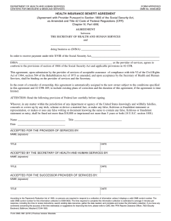


© Copyright 2026