
PREPARATION AND CHARACTERIZATION OF LIGNIN NANOFIBRE-BASED MATERIALS OBTAINED BY ELECTROSTATIC SPINNING
PREPARATION AND CHARACTERIZATION OF LIGNIN NANOFIBRE-BASED MATERIALS OBTAINED BY ELECTROSTATIC SPINNING by James Ian Dallmeyer A THESIS SUBMITTED IN PARTIAL FULFILLMENT OF THE REQUIREMENTS FOR THE DEGREE OF DOCTOR OF PHILOSOPHY in THE FACULTY OF GRADUATE STUDIES (Forestry) THE UNIVERSITY OF BRITISH COLUMBIA (Vancouver) March 2013 © James Ian Dallmeyer, 2013 Abstract Electrostatic spinning was investigated as a means to generate nanofibre-based materials from lignin. Kraft, organosolv, lignosulfonate, and pyrolytic lignins were found to be prone to electrospray, resulting in the formation of droplets instead of fibres upon electrical charging of their solutions in most cases. It was observed that the addition of a small amount of poly(ethylene oxide) (PEO) to the spinning solution was an effective strategy to promote the formation of uniform fibres. Studies on the shear and elongational rheology of the spinning solutions were conducted to understand the mechanism underlying the improved process stability that resulted from the addition of PEO to lignin solutions. It was found that the shear rheology was changed to a small extent upon addition of PEO to the spinning solution, while studies using capillary breakup extensional rheometry revealed that PEO addition induced non-Newtonian, strain hardening behaviour to lignin solutions, which was undetectable in shear rheology studies. The concentration of lignin in solution, concentration of PEO, and molecular weight of PEO were shown to influence the elongational fluid properties, which displayed a strong correlation with the fibre diameter. Once the rheology of the spinning solution was characterized, attention was focused on oxidative thermostabilization and carbonization of electrospun nonwoven fabrics. It was found that incorporating different amounts of Kraft lignin fractions in electrospun fibres allowed the preparation of interesting material morphologies depending on the thermal softening characteristics of Kraft lignin fractions. Two interesting types of materials were prepared by controlling the composition of lignin fabrics and processing parameters. The first was a novel stimuli-responsive film material with a reversible ability to change shape in response to moisture. The second type was an interconnected carbon nanofibre network which displayed interesting mechanical, surface, and electrical properties. The structure and properties of Kraft lignin fractions were investigated by thermo-rheological analysis, nuclear magnetic resonance spectroscopy, gel permeation chromatography, and light scattering to understand the role of lignin structure in determining the properties of thermostabilized and carbonized lignin fabrics. The electrospun fabrics were also characterized by atomic force microscopy, microtensile testing, nitrogen adsorption, X-ray diffraction, and Raman spectroscopy. i Preface A version of chapter 3 has been published in the Journal of Wood Chemistry and Technology (Dallmeyer, I., Ko, F., Kadla, J.F. J. Wood Chem. And Tech. 2010, 30, 4, 315329). I conducted all of the experiments and data analysis described and wrote the manuscript, and Professors Frank Ko and John Kadla suggested corrections to improve the manuscript. A version of chapter 4 has been submitted for publication (Dallmeyer, I., Ko, F., Kadla, J.F. submitted for review in 2012) I conducted all of the experiments described in chapter 4 and wrote the manuscript, and Professors Frank Ko and John Kadla advised me with corrections to improve the manuscript. The contribution of Professor Savvas Hatzikiriakos, who also advised me with suggestions to improve the manuscript, is also acknowledged. Chapter 5 includes some data that was collected by Dr. Sudip Chowdhury. He was responsible for conducting thermorheological analysis of Kraft lignin fractions and wrote portions of the sections describing the data (section 5.6). I wrote everything else in Chapter 5 and conducted all of the other experimental work. Mr. Li Ting Lin, Ms. Yingjie (Phoebe) Li, and Ms. Nai-Yu Teng helped conduct some of the experimental work described in Chapter 6. Li Ting conducted some of the tensile testing (section 6.3) and collected some of the Raman spectroscopy data (section 6.6). Phoebe Li prepared electrospun polyacrylonitrile (PAN) fibres for comparison with fibres prepared from lignin. Nai-Yu Teng collected the x-ray diffraction patterns shown in the Appendix. I conducted all of the rest of the experimental work and wrote the entire manuscript. ii Table of Contents Abstract ..................................................................................................................................... i Preface ...................................................................................................................................... ii Table of Contents ................................................................................................................... iii List of Tables .......................................................................................................................... vi List of Figures ........................................................................................................................ vii List of Symbols and Abbreviations ...................................................................................... xi Acknowledgements .............................................................................................................. xiii Dedication ............................................................................................................................. xiv Chapter 1. Introduction ......................................................................................................... 1 1.1 Motivation for development of advanced lignin-based nanofibre materials:........................ 1 1.2 Lignin biosynthesis and structure: ........................................................................................ 5 1.3 Isolation of lignin by chemical pulping: ............................................................................. 11 1.4 Electrospinning: .................................................................................................................. 16 1.5 Stimuli-responsive shape memory materials from lignin: .................................................. 22 1.6 Production of carbon fibres from lignin: ............................................................................. 26 Chapter 2. Materials and experimental methods............................................................... 31 2.1 Materials: ............................................................................................................................ 31 2.2 Fractionation of SKL by sequential solvent extraction: ...................................................... 32 2.3 Lignin characterization: ...................................................................................................... 32 2.3.1 Thermorheological analysis of F4 and F1-3:..................................................................... 32 2.3.2 Acetylation of lignin: ...................................................................................................... 33 2.3.3 Characterization of lignin by nuclear magnetic resonance (NMR) spectroscopy: ......... 33 2.3.4 Characterization of lignin molecular weight distribution by gel permeation chromatography and multi-angle laser light scattering (GPC-MALLS): .................................... 34 2.4 Preparation of lignin-PEO solutions for electrospinning: ................................................... 34 2.5 Electrospinning: .................................................................................................................. 35 2.6 Rheological characterization of electrospinning solutions: ................................................ 36 2.6.1 Steady shear viscosity measurements: ............................................................................ 36 iii 2.6.2 Small amplitude oscillatory shear rheometry: ................................................................ 36 2.6.3 Capillary breakup extensional rheometry: ...................................................................... 36 2.7 Thermostabilization of electrospun fabrics: ........................................................................ 37 2.8 Carbonization of electrospun fabrics: ................................................................................. 38 2.9 Characterization of electrospun fabrics:.............................................................................. 39 2.9.1 Optical and scanning electron microscopy of fibres obtained by electrospinning: ........ 39 2.9.2 Atomic force microscopy (AFM) of thermostabilized electrospun materials: ............... 39 2.9.3 Characterization of mechanical properties of electrospun fabrics: ................................. 40 2.9.4 Electrical conductivity of carbonized materials: ............................................................ 40 2.9.5 BET surface area measurements on carbonized electrospun materials: ......................... 41 2.9.6 Characterization of carbonized materials by Raman spectroscopy: ............................... 41 Chapter 3. Electrospinning of technical lignins for the production of fibrous networks ................................................................................................................................................. 42 3.1 Introduction: ........................................................................................................................ 42 3.2 Electrospinning of technical lignin solutions without PEO: ............................................... 42 3.3 Electrospinning of lignin with addition of PEO:................................................................. 44 3.4 Effect of shear viscosity on fibre formation and diameter: ................................................. 48 3.5 Conclusion: ......................................................................................................................... 52 Chapter 4. Effect of elongational rheology on electrospinning of softwood Kraft lignin54 4.1 Introduction: ........................................................................................................................ 54 4.2 Solutions: ............................................................................................................................ 56 4.3 Dynamic shear rheometry: .................................................................................................. 56 4.4 Elongational rheometry by CaBER: ................................................................................... 58 4.5 Ability of F4 and F4/PEO solutions to form fibres during electrospinning: ........................ 64 4.6 Correlation of relaxation time with fibre diameter: ............................................................ 67 4.7 Conclusion: ......................................................................................................................... 69 Chapter 5. Preparation of moisture-responsive lignin-based materials .......................... 70 5.1 Introduction: ........................................................................................................................ 70 5.2 Electrospinning of lignin fractions F4 and F1-3: ................................................................... 70 5.3 Thermostabilization of nonwoven fabrics:.......................................................................... 73 5.4 Moisture-responsiveness, shape change, and shape recovery: ............................................ 76 5.5 AFM imaging of moisture-responsive films: ...................................................................... 79 5.6 Dynamic rheology of lignin fractions: ................................................................................ 83 iv 5.7 NMR characterization of lignin fractions: .......................................................................... 87 5.8 Characterization of molecular weight by GPC-MALLS: ................................................... 94 5.9 Conclusion: ......................................................................................................................... 97 Chapter 6. Preparation and characterization of interconnected lignin-based carbon nanofibre materials ............................................................................................................... 98 6.1 Introduction: ........................................................................................................................ 98 6.2 Carbonization of thermostabilized electrospun nonwovens: .............................................. 98 6.3 Effect of inter-fibre bonding on mechanical properties: ................................................... 101 6.4 Electrical conductivity of carbonized fabrics:................................................................... 104 6.5 BET surface area of carbonized fibres: ............................................................................. 106 6.6 Raman spectroscopy of carbonized fibres: ....................................................................... 106 6.7 Conclusion: ....................................................................................................................... 112 Chapter 7. Concluding Remarks ....................................................................................... 114 References………………………………………………………………………………….122 Appendix………………………………………………………………………………...…151 v List of Tables Table 1.1: Pulping processes and reactive species.................................................................. 12 Table 3.2: Mean fibre diameters + standard deviation (n = 200) for 99/1 lignin/PEO fibres obtained from different technical lignins ................................................................................ 47 Table 4.1: Fluid compositions, viscosity , relaxation time , surface tension , and corresponding fibre diameters. - = too small to measure, *= incomplete fibre solidification during spinning, x = no fibres formed, n/a = not applicable. n represents the number of samples used to obtain solution properties. ............................................................................ 55 Table 5.1: Spinning solution compositions, thermostabilization heating rates, and resulting morphology after heating electrospun F4/F1-3 fibres ............................................................... 73 Table 5.2: Integration of quantitative 13C-NMR spectra of F1-3 and F4. The area of the aromatic region (162-102 ppm) was set to 600. The reported values are therefore reported as quantities per 100 aromatic rings. Ar = aromatic, Alk = alkyl. .............................................. 93 Table 6.1: Diameters of as-spun, thermostabilized, and carbonized lignin NBF materials.. 101 Table 6.2: Mechanical properties of bonded and non-bonded fabrics before and after carbonization at 1000oC. Values are expressed as mean + one standard deviation based on measurements on N samples. ................................................................................................ 101 vi List of Figures Figure 1.1: Lignin monomers (a,b,c) and subunits (d,e,f) (a) p-coumaryl alcohol (b) coniferyl alcohol (c) sinapyl alcohol (d) p-hydroxyphenyl (H) subunit (e) guaiacyl (G) subunit (f) syringyl (S) subunit ................................................................................................. 6 Figure 1.2: Characteristic linkages in lignin (a) -aryl ether (-O-4) (b) phenylcoumaran (5) (c) resinol (-) (d) biphenyl (5-5’) (e) biphenyl ether (4-O-5) (f) dibenzodioxocin (-O4/-O-4/5-5’) ............................................................................................................................ 8 Figure 1.3: Schematic illustration of electrospinning process ............................................... 17 Figure 1.4: Scanning electron micrograph of electrospun PAN nanofibre nonwoven fabric.18 Figure 3.1: SEM images of SKL solutions electrospun at 40 wt% (a), and 50 wt% (b). Scale bar = 100 m ........................................................................................................................... 43 Figure 3.2: SEM images of 95/5 and 99/1 SKL/PEO fibres electrospun from solutions at different concentrations. (a) 95/5, 20 wt%, (b) 95/5, 25 wt%, (c) 95/5, 30 wt%, (d) 99/1, 30 wt%, (e) 99/1, 35 wt%, (f) 99/1, 40 wt%. Scale bar = 20 m (2000X magnification). .......... 45 Figure 3.3: SEM images of lignin fibres electrospun from 99/1, lignin/PEO solutions using different technical lignins. (a) HKL 40 wt%; (b) PL 40 wt%; (c) SL 30 wt%; (d) SOL 50 wt%; (e) HOL 40%; (f) LS 30 wt%. All scale bars = 20 m (2000X magnification). ........... 46 Figure 3.4: Plot of fibre diameter vs. concentration for the 99/1 SKL/PEO system. Diameters are reported as mean + standard deviation, based on 100 fibers for each solution and n=2 solutions prepared at each concentration. ............................................................................... 48 Figure 3.5: Plot of specific viscosity vs. concentration for SKL and SKL/PEO systems. .... 49 Figure 4.1: (a) Stress sweep and (b) frequency sweep data for F4 and F4/PEO solutions with F4 concentration = 40 wt%...................................................................................................... 56 Figure 4.2: Representative thinning profiles of F4 and F4/PEO solutions. ............................ 58 Figure 4.3: (a) Transient elongational viscosity of F4/PEO solutions with F4 conc. = 40 wt%. (b) Semi-log plot of thinning profiles of F4/PEO solutions with F4 conc. = 40 wt%. (c) Region of CaBER data close to filament breakup showing data scatter at small filament diameters.. ............................................................................................................................... 61 Figure 4.4: SEM images of fibres electrospun from solutions with different compositions . 65 vii Figure 4.5: SEM image of fibres electrospun from 50 wt% SKL solution without PEO. a) Purified SKL fraction F4. b) SKL without purification. (Scale bar = 20 m) ........................ 66 Figure 4.6: Mean fibre diameter vs. relaxation time () for F4/PEO solutions ..................... 67 Figure 5.1: Photograph of electrospun softwood Kraft lignin nonwoven fabric after electrospinning ........................................................................................................................ 71 Figure 5.2: SEM images of electrospun fibres obtained from solutions containing (a) 32 wt% F1-3, 0.2 wt% PEO and (b) 32 wt% F4, 0.2 wt% PEO. Scale bar = 50 m. .................... 72 Figure 5.3: Photograph of electrospun lignin fabric after thermostabilization at 250oC in air. Unfused fibres are shown........................................................................................................ 74 Figure 5.4: SEM images of electrospun fibres containing different ratios of F4/F1-3 after thermostabilization at 5 oC/min to 250oC, in air. (a) F4/F1-3 = 100/0, (b) 70/30, (c) 60/40, d) 50/50. ...................................................................................................................................... 75 Figure 5.5: Thermostabilized (5oC/min) 50/50 F4/F1-3 film placed on moist paper (a-d), then moved to dry paper (e-h)......................................................................................................... 77 Figure 5.6: (a) 3-dimensional AFM height image and (b) corresponding adhesion force map of a 50/50 F4/F1-3 moisture-sensitive film heated at 5 oC/min. The size of the imaged area was 30 x 30 m .............................................................................................................................. 80 Figure 5.7: Adhesion force sections from AFM images on 50/50 F4 blend materials (top) and a film containing only F1-3. ..................................................................................................... 81 Figure 5.8: Adhesion force superimposed on a height image of a moisture responsive film with F4/F1-3 ratio of 50/50. ...................................................................................................... 82 Figure 5.9: Thermorheological responses of lignin F1-3 and F4 fractions. Average (n = 3) first heat storage (G’) modulus (Top), and tan δ (Bottom) are presented. ..................................... 84 Figure 5.10: Dynamic rheology of electrospun fabrics of F1-3 and F4 blend (50/50). Effects of heating rates on storage modulus (Top) and tan (Bottom) are presented. ........................... 86 Figure 5.11: 1H-NMR of acetylated F4 (top) and F1-3 (bottom) from 2.6-1.7 ppm, showing the peaks corresponding to acetylated phenolic (2.5-2.2 ppm) and aliphatic (2.2-2.0 ppm) hydroxyl groups ...................................................................................................................... 88 Figure 5.12: 13C-NMR of acetylated F4 (top) and F1-3 (bottom) in the region 172-167 ppm, corresponding to carbonyl carbons of acetyl groups .............................................................. 89 viii Figure 5.13: Oxygenated aliphatic region (1H: 2.7-6.5 ppm, 13C: 48-95 ppm) of HSQC spectra of F4 (top) and F1-3 (bottom). Unassigned peaks are traced in black. ......................... 91 Figure 5.14: 13C-NMR of F4 (top) and F1-3 (bottom) (a) etherified C-4 in guaiacyl units (b) -O-4,13C ’, -5, 13CcC-O-4 C’; d) C-O-4, ; (e) methoxyl. ................................................................................................................................................. 92 Figure 5.15: Light scattering data showing elution curves obtained from GPC-MALLS for acetylated fractions. Black: F1-3, 3 mg.mL-1, red: F4, 1 mg.mL-1, green: F4, 2 mg.mL-1, blue: F4 3 mg.mL-1 ................................................................................................................................ 95 Figure 6.1: (a) Non-bonded F4 fibres (NBF-250) and (b) Bonded 70/30 (w/w) F4/F1-3 fibres (BF-250) after thermostabilization at 250oC. Scale bar = 20 m. .......................................... 99 Figure 6.2: (a) Non-bonded lignin-based carbon fibres (NBF-1000) and (b) Bonded (w/w) F4/F1-3 carbon fibres (BF-1000) after carbonization at 1000oC. Scale bar = 5 m. .............. 100 Figure 6.3: Photographs demonstrating the differences in flexibility between (a) NBF and (b) BF after carbonization (Tc = 600oC). Slight bending resulted in breaking of the NBF material (a) while BF materials were relatively flexible (b). ................................................ 103 Figure 6.4: Typical Raman spectrum of carbonized lignin-based fibres in the wavenumber region 900-1800 cm-1. The D-band (~1310 cm-1) is fitted with a Lorentzian line shape and the G-band (1580 cm-1) is fitted with a Breit-Wigner-Fano (BWF) lineshape, both shown in black, and the cumulative spectrum based on fitting is shown in red. .................................. 107 Figure 6.5: ID/IG from Raman spectra as a function of carbonization temperature for PAN, NBF, and BF. Error bars represent plus/minus one standard deviation. PAN = ♦, NBF = ■, BF = ▲. ................................................................................................................................ 108 Figure 6.6: Full-width at half-maximum (FWHM, cm-1) of the (a) D-band and (b) G-band as a function of carbonization temperature from Raman spectra of PAN, NBF, and BF. PAN = ♦, NBF = ■, BF = ▲. Error bars represent plus/minus one standard deviation. .................. 108 Figure 6.7: Positions (cm-1) of (a) D-band and (b) G-band as a function of carbonization temperature from Raman spectra of PAN, NBF, and BF. PAN = ♦, NBF = ■, BF = ▲. Error bars represent plus/minus one standard deviation. ............................................................... 109 Figure A1: Raw data for plot of specific viscosity vs. concentration (Figure 3.5)………...151 Figure A2: Fitting to obtain slopes of specific viscosity vs. concentration (Figure3.5)...…152 Figure A3: Raw data for stress sweep (Figure 4.1a)……………………...………………..153 ix Figure A4: Raw data for frequency sweep (Figure 4.2b)……………………......…….…..154 Figure A5: Example of CaBER data to obtain relaxation times (Chapter 4)…………..….155 Figure A6: Aliphatic region from HSQC of F4SKL in DMSO-d6………..……………….156 Figure A7: Aromatic region from HSQC of F4SKL in DMSO-d6………………...….…...157 Figure A8: Aliphatic region from HSQC of F1-3SKL in DMSO-d6…………………...…..158 Figure A9: Aromatic region from HSQC of F1-3SKL in DMSO-d6………………………..159 Figure A10: Wide angle X-ray diffraction patterns of BF (top) and NBF (bottom) carbonized at different temperatures………………………………………………………………….…160 x List of Symbols and Abbreviations CF = carbon fibre CNF = carbon nanofibre AC = activated carbon ACF = activated carbon fibre SRM = stimuli-responsive material SMM = shape memory material SKL = softwood Kraft lignin HKL = hardwood Kraft lignin SOL = softwood organosolv lignin HOL = hardwood organosolv lignin PL = pyrolytic lignin SL = sulfonated Kraft lignin LS = lignosulfonate DMF = N,N’-dimethylformamide PEO = poly(ethylene oxide) PAN = poly(acrylonitrile) PVA = poly(vinyl alcohol) NCC = nanocrystalline cellulose SEM = scanning electron micrograph F4 = softwood Kraft lignin fraction 4 F1-3 = softwood Kraft lignin fraction 1-3 = average shear viscosity obtained from steady shear rheometry s = viscosity of solvent determined by capillary viscometer at 25oC sp = specific viscosity = ( – s)/s G’ = storage modulus G” = loss modulus = angular frequency in radians |*()| = magnitude of the complex viscosity = √(G’2+G”2) CaBER = capillary breakup extensional rheometer xi Dmid(t) = midpoint diameter of thinning fluid filament measured by CaBER D1 = initial midpoint filament diameter after initial step strain during CaBER λ = characteristic time scale of tensile stress growth in uniaxial elongational flow (relaxation time) G = elastic modulus = surface tension Tc = maximum carbonization temperature NBF = non-bonded fibres NBF-250 = non-bonded fibres thermostabilized at 250oC NBF-600 = non-bonded fibres carbonized at 600oC NBF-800 = non-bonded fibres carbonized at 800oC NBF-1000 = non-bonded fibres carbonized at 1000oC BF = bonded fibres BF-250 = bonded fibres thermostabilized at 250oC BF-600 = bonded fibres carbonized at 600oC BF-800 = bonded fibres carbonized at 800oC BF-1000 = bonded fibres carbonized at 1000oC = electrical conductivity SBET = Brunaer-Emmett-Teller specific surface area FWHM = full-width at half-maximum ID/IG = Ratio of the intensities of the D- and G- band measured with Raman spectroscopy xii Acknowledgements I would like to first acknowledge and thank my research supervisor John Kadla for bringing me into the Advanced Biomaterials Chemistry lab and supporting me for the last five years, and for his patience in training me. His example has strongly shaped my approach to science and will continue to do so throughout my career. I would also like to thank my supervisory committee members, Professors Frank Ko, Savvas Hatzikiriakos, and Rodger Beatson. My eyes are open to an endless world of possibilities to explore in the field of polymer science because of them and I am eternally grateful for the guidance that I have received during my time at UBC. I also must specifically thank several people from the Biomaterials Chemistry lab who have helped me along the way. Dr. Yong-Sik Kim took me under his wing near the beginning of my Ph.D program and prepared me for the long road ahead. I am forever grateful that he took the time to train me in the lab and I am not sure if I would have made it through the first difficult months without him. I’d also like to thank Reza Korehei and Ana Filipa Xavier for their consistently positive, contagious energy which rarely diminished over the last five years we have worked together. Their genuinely good nature was especially comforting at those times over the last five years when things just did not go according to plan, which happened often to say the least. I also wish to express my thanks and best wishes to everyone else from Biomaterials Chemistry, AMPEL, chemical engineering, and other labs and departments who helped me along the way. I’d also like to thank my musical friends for providing much needed distraction from the toils of Ph.D research. In no particular order and hopefully not forgetting any, they are Peter Arcese, Athena McKown, Sierra Curtis-McClane, Jamie Leathem, Laurie Marczak, Trevor Lantz, Joe Bennett, Chris Bater, Pete Cramer, Luc Desmarais, Rod Docking, Christian Beaudrie, Isla Myers-Smith, Sarah Gergel, Paolo Segre, and the Steves. Thank you all so much. I really enjoyed our time spent together and have each of you to thank for a decent portion of my sanity. Finally, I’d like to acknowledge generous support from North Carolina State University/United States Department of Agriculture and the Natural Science and Engineering Research Council of Canada. Research would not happen without the support of parties dedicated to the advancement of science. xiii Dedication I do not believe I could have completed this research without the love and support of my family. This dissertation is dedicated to my parents Cynthia and Scott, my sister Emily, and my brothers Bill and Rick. You were always there for me and it has made all the difference. xiv Chapter 1. Introduction 1.1 Motivation for development of advanced lignin-based nanofibre materials: There is currently increasing interest in replacing non-renewable petroleum-based fuels, chemicals, and materials with products derived from renewable resources.1–6 In theory, biorefineries of the future will be able to meet the energy and material needs of society by producing biofuels and other products from biomass such as wood and grass. Because lignin is an integral component of biomass, biorefineries will inevitably produce it as a coproduct.1,5,6 However, lignin is currently under-utilized in spite of the fact that it is known that utilization of lignin in value-added applications could benefit the overall sustainability of biorefinery processes.6,7 Lignin is also currently generated in large quantities by industrial pulping processes (predominantly Kraft pulping)8,9 which are difficult to measure precisely, but were estimated in 1990 at 138.5 million kg/year worldwide.10,11 Gellerstedt and coworkers9 have more recently estimated that assuming 10% of lignin from European Kraft pulp mills were isolated, 1.5 million tons of Kraft lignin could be made available for valueadded products. However, as of 1998, only about 1% of all lignin generated in paper production worldwide was isolated and sold,12 mostly as lignosulfonates. Most of the lignin generated by current industrial processes is Kraft lignin from black liquor, which plays an important role as a fuel in the energy balance of modern Kraft pulp mills. However, the capacity of the recovery boiler is a bottleneck in the production of pulp.8,9 Removing some lignin from black liquor prior to burning it in the recovery boiler could potentially increase pulp production while also producing lignin for potential value-added applications. Current applications of industrial (or “technical”) lignins include relatively low value dispersants, emulsion stabilizers, surfactants, and binders.11,12 However, other higher value opportunities for lignin utilization as a feedstock for chemicals and materials exist.7,13 A large body of research has been conducted and considerable research activity is currently underway in the area of chemical modification of lignin for use in polymer blends, thermoplastics, polyurethanes, stimuli-responsive materials, hydrogels, and various resin systems.4,14–27 Despite continued research on lignin utilization, commercialization of lignin1 based materials has proven difficult.11–13 The relatively limited utilization of industrial lignins for many applications is related to its highly complex, heterogeneous chemical structure and variability among different types of lignin which makes processing of lignin and control over its physical properties very challenging. However, several decades of research has allowed improvements in properties of lignin-based materials to be achieved by clarifying the relationships between the complex structure and macromolecular properties of different lignins, processability, and material properties. Advances in science and technology coupled with a growing desire to use renewable resources in place of fossil reserves present exciting new opportunities for the development of novel advanced ligninbased materials. Electrostatic spinning, commonly referred to as electrospinning,28–30 is hereby proposed as a promising strategy to novel materials from technical lignins. Electrospinning is capable of producing continuous fibres with very small diameters in the range of nanometers to microns from an enormous variety of materials.28–30 Electrospinning is attractive due to its ability to produce continuous fibres with diameters from 10 nm to several micrometers (1 nm = 10-9 m) using a wide variety of materials. Some examples include PAN,31,32 cellulose acetate,33 keratin,34,35 alginate,36 chitosan,37 bombyx mori silk38,39 poly(methyl methacrylate) (PMMA),40 poly(L-lactide) (PLLA),41 as well as inorganic materials.42 Due to its enormous versatility for processing a wide range of polymers, electrospinning is a promising method to produce a variety of nanofibre-based materials, including nanocomposites,43–46 fibrous catalyst substrates,47,48 drug delivery devices,49 tissue engineering scaffolds,50,51, and nanowires.52,53 The electrospinning technique offers unique advantages and presents exciting opportunities for development of lignin-based materials. However, electrospinning of lignin presents a few challenges compared to synthetic polymers which are related to the complex, branched, heterogeneous, and widely varying lignin structure and physical properties. Chapters 3 and 4 will be aimed at characterizing the behaviour of lignin during electrospinning and will place an emphasis on understanding the relationship between the rheology of the spinning solution and the formation of electrospun fibres. From there the possibility of using electrospun lignin fibres as precursors for ligninbased materials with interesting properties will be explored. 2 One class of materials that is currently receiving widespread attention for a variety of applications is polymeric stimuli-responsive materials (SRMs). SRMs are often referred to as “smart” materials due to the capability of changing their properties in response to external stimuli (e.g. chemical, light, temperature, pH, external electric and magnetic fields), based on the dynamic rearrangement of supramolecular polymer networks. The numerous exciting properties and applications of SRMs have been reviewed extensively.54–60 A highly interesting sub-class of SRMs are materials capable of fixing temporarily “programmed” shapes and returning to their original shape in response to external stimuli such as temperature,61 light,62 electricity,63 magnetism,64 or moisture.65–76 These SRMs are commonly referred to as shape memory materials (SMMs). Polymer SMMs have received increasing attention in recent years due to exciting possibilities in potential biomedical applications77 as well as in sensors78 and actuators.79 Polymers intrinsically show shape memory on the basis of entropic elasticity, and hence a wide variety of polymer SMMs can be designed.80–82 The shape memory effect is due to the combined action of two or more distinct phases or segments, where one phase acts as a “switch” capable of undergoing a transition or change in conformation or mobility in response to a stimulus, and the other segment remains relatively immobile and allows the material to “remember” its permanent shape. The presence of a physically and/or chemically cross-linked network structure is another important characteristic of SMMs.80–82 Numerous SMMs based on synthetic polymers including polyurethanes65,69–71,73–75, polyvinyl alcohol,66,67 poly(e-caprolactone),83 and others80–82 as well as polymer blends84–87 and composite systems64,72,76,88 have been reported. The advantage of using synthetic materials in design of SMMs is the versatility in generating materials with well-defined switching characteristics89 and the ability to memorize multiple shapes.88,90–92 Use of bio-based materials72,76,93–95 has also been reported in the preparation of SMMs, but has received considerably less attention. The inspiration for design of SRMs/SMMs has grown in relation with the observation of stimuli-responsiveness in biological systems.55 Notably, while SRMs and SMMs have emerged as an important class of novel advanced materials, the preparation of SRMs based on lignin has not received much attention.23 Electrospinning has also been shown to be an effective method of preparing a variety of interesting SRMs. The high surface area to volume ratio of electrospun fibres has been reported to be advantageous for the preparation of SRMs with high sensitivity to 3 external stimuli.96 A portion of the research described in chapter 5 will therefore be devoted to investigating the possibility of fabricating SRMs and SMMs through electrospinning of lignin. Carbon materials such as lignin-based carbon fibre (CF) and porous carbons such as activated carbon (AC) and activated CF (ACF) are another particularly promising potential application for lignin.9,97–108 The combination of high strength and stiffness coupled with low density make high-performance CF an ideal reinforcement for high-strength, lightweight composite materials used in aerospace, automotive, marine, and sporting goods applications.98,99,109,110 Carbon materials including CF and AC also have numerous additional applications, including adsorbents,111 catalyst supports,112,113 biomedical materials,114 electromagnetic shielding,115 and other electrical applications115 such as electrochemical double-layer capacitors for energy storage or capacitive deionization,116–121 Li+-ion batteries,122–124 fuel cells,125,126 and dye-sensitized solar cells.127 Carbon nanofibres prepared through electrospinning are being intensively investigated for potential application in the areas listed above.128 Unfortunately, lignin is relatively difficult to process into high strength CF, with continued research resulting in mechanical properties unsuitable for structural composites.98–100,110 The tensile strength and modulus of lignin-based CF is still relatively low compared to those of CF derived from synthetic poly(acrylonitrile) (PAN)based copolymers.110 On the other hand, superior mechanical strength is not required for all applications, the relatively high cost of PAN is a limiting factor in its widespread application,99 and there is a need to replace non-renewable petroleum-based materials such as PAN with renewable precursors. Reduction of the fibre diameter below that of conventional micron-sized fibres through electrospinning could improve the material properties and expand the applications of lignin-based CFs. It is known that the mechanical properties of carbon fibre increase with decreasing diameter.98,100,129,130 Decreasing the fibre diameter also increases the available surface area for interaction with matrices thus producing a composite with better shear strength.31 Furthermore, the increased specific surface area provided by a reduction in the fibre diameter can benefit the numerous nonstructural applications of CF mentioned above. While lignin-based CF properties must be improved further to compete with PAN and pitch-based CF in terms of mechanical properties, combining an understanding of lignin properties with novel processing strategies 4 such as electrospinning may allow further improvement of properties and expansion of the potential applications of lignin-based CFs to the other areas listed above. CF materials obtained from lignin are therefore a second class of materials that will be investigated in chapter 6. In order to effectively apply electrospinning in the fabrication of novel lignin-based nanofibre materials, it is necessary to first understand lignin. As an introduction to the proposed research, the structure and isolation of lignin will be discussed first in section 1.2 and 1.3, respectively. The electrospinning process will then be discussed in detail in section 1.4. SRMs and SMMs will be then discussed in section 1.5 and the prospect of using lignin in SRM/SMM fabrication will be presented. Finally in section 1.6, a discussion of CF processing, structure and properties and previous research on lignin-based CF will be presented 1.2 Lignin biosynthesis and structure: Lignins are one of the three main constituents of the cell walls and extracellular space of arborescent gymnosperms and angiosperms. Lignins serve as structural elements in plant stems, imparting rigidity and resistance to impact, compression, and bending. In addition, they facilitate the transport of water, nutrients, and metabolites, and provide resistance against degradation by microorganisms.131 Native lignins are polyaromatic heteropolymers derived from copolymerization of mainly three p-hydroxycinnamyl alcohol monomers, referred to as monolignols.132,133 These are p-coumaryl, coniferyl, and sinapyl alcohols, which differ in the number of methoxyl groups at the 3 and 5 positions of the aromatic ring. Other monomers also take part in lignification to a lesser degree. Hydroxycinnamates are one example of monolignols other than hydroxycinnamyl alcohols.134 This is an important distinction to accurately represent the plasticity of lignification and the variety of possible structures, but for a general explanation of lignin structure, consideration of the three primary monolignols is illustrative. The primary monolignols give rise to the p-hydroxyphenyl (H), guaiacyl (G), and syringyl (S) units in the lignin polymer through a combinatorial radical coupling process. Softwood (gymnosperm) lignins consist of mainly G units with low levels of S and H units, while hardwood 5 (angiosperm) lignins consist mainly of G and S units with low levels of H units, and grasses have comparable amounts of S and G units, with higher amount of H units compared to hardwoods and softwoods.132,133 Figure 1.1: Lignin monomers (a,b,c) and subunits (d,e,f) (a) p-coumaryl alcohol (b) coniferyl alcohol (c) sinapyl alcohol (d) p-hydroxyphenyl (H) subunit (e) guaiacyl (G) subunit (f) syringyl (S) subunit The biosynthesis of lignin precursors from carbohydrates follows the shikimic acid pathway, an essential biosynthetic pathway with phenylalanine and tyrosine as products. The first evidence for the importance of this pathway was provided by Brown and Neish135 using 14 C-labelled shikimic acid and phenylalanine. These investigators demonstrated that these labeled compounds were efficient precursors for lignins in wheat and maple. Numerous subsequent studies indicate that the shikimic acid pathway is responsible for monolignol biosynthesis.136 Phenylalanine is converted to the p-hydroxycinnamyl alcohol lignin precursors through an enzymatically mediated series of reactions, which has been studied intensively by many researchers.132,133,137–143 It should be noted that different pathways to the p-hydroxycinnamyl alcohols are possible due to the fact that multiple isoforms of different enzymes exist and are differentially expressed depending on the stage of development and 6 environmental cues.132,144,145 Also, additional complexity arises from the fact that pathway intermediates may affect synthesis or activity of enzymes involved in the pathway.132 During lignification, monolignols are coupled in an end-wise manner to form the lignin polymer. In gymnosperms and some angiosperms, monolignols are transported to the cell wall from the cambial tissue in the form of 4-O--D-glucosides, which are presumed to be the storage and/or transport form.146 After transport, monolignols are oxidized to phenoxy radicals by the action of laccases and/or peroxidases.132,133,147 Dehydrogenation of a monolignol leads to the formation of a phenoxy radical. Due to the ability of electrondelocalized radicals to couple at various sites, different linkage structures are possible133 (Figure 1.2). The predominant linkages are the -O-4 (-aryl ethers), which account for roughly half the linkages in lignin, but other linkages, such as the -5 (phenylcoumaran), 55’ (biphenyl), 4-O-5’ (biphenyl ether), -’ (pinoresinol), dibenzodioxocin (combination of 5-5’/-O-4/-O-4), and -1 linked structures are also present in the lignin polymer. It is important to note that the type of monolignol affects the possible outcomes of radical coupling reactions. For example, the aromatic C5 position is available for coupling in coniferyl, but not sinapyl alcohol. This explains why syringyl (S) lignins have a higher proportion of -O-4 units compared to guaiacyl (G) lignins, because the aromatic C-5 position is unavailable for coupling. Following radical coupling, re-aromatization reactions occur. In the formation of a -O-4 linkage, nucleophilic addition of H2O to either side of the planar quinone methide intermediate results in two distinct stereoisomers, threo- (syn-, RR/SS), and erythro-(anti-, RS/SR), which are present in kinetically controlled amounts.133 7 Figure 1.2: Characteristic linkages in lignin (a) -aryl ether (-O-4) (b) phenylcoumaran (-5) (c) resinol (-) (d) biphenyl (5-5’) (e) biphenyl ether (4-O-5) (f) dibenzodioxocin (-O-4/-O-4/5-5’) Much of our understanding of the mechanism of lignification comes from early experiments on synthetic lignin-related polymers by Freudenberg.148,149 These types of synthetic lignins are commonly referred to as dehydrogenation polymers (DHPs). The results of DHP experiments support the hypothesis that the polymer grows by combination of a radical at the phenolic end of a growing oligolignol with another radical of a monolignol, most often at the monolignol position. For example, the structure of DHPs prepared by the dehydrogenative polymerization of coniferyl alcohol in the presence of horseradish peroxidase (HRP) and H2O2 depended on whether the monomers were introduced all at once (“Zulaufverfahren”) or gradually over a longer period of time (“Zutropfverfahren”).136,148 In the first case, dehydrodimerization reactions between monolignols are favored. In dehydrodimerization reactions the products always consist of coupling of at least one of the monolignols at its -position. An enlightening observation 8 from DHP experiments is that the frequency of -O-4 units is lower when monomers are added in bulk all at once compared to gradual addition. Gradual addition shifts the favored outcome from dehydrodimerization to coupling of an oligolignol with monolignol radical and results in a greater -O-4 content. Since the -O-4 linkage is the most abundant linkage in lignin, these results suggest that the outcome of coupling reactions may be regulated in planta by control of the monomer supply rate. Model experiments suggest that the outcome of coupling reactions also depends on the rate of radical generation, the presence of polysaccharides, and the presence of the growing lignin polymer chain.150–153 Since several coupling outcomes with different probablities of occurring are possible between monolignols and the growing polymer based on a combination of several factors, lignin polymerization can be viewed as a combinatorial process resulting in a non-repeating sequence of monomer units.132,133 The result of this combinatorial process is a polymer chain with an enormous variety of possible chain sequences and conformations. Through the mechanism described above, plant cells are able to deposit lignins with different structure and orientation in different areas of the cell wall (P1, S1, S2) and middle lamella (ML). Lignification is one of the final stages of xylem cell differentiation, with lignin deposition occurring after carbohydrate deposition. The process begins at the cell corners in the primary wall, spreading to the middle ML and S1 region of the secondary wall, and finally throughout the secondary wall around the lumen. When lignification is complete, the highest lignin concentration is in the ML region, but since the ML accounts for a relatively small volume fraction of wood, the highest total amount of lignin is in the secondary wall.154 A notable area of ongoing research is the precise nature of the initiation sites for lignification, which may be related to the regulation and control of lignin structure. Davin, Lewis and coworkers have suggested that arrays of dirigent proteins play a similar role as that observed in lignan biosynthesis, by controlling the outcome of phenoxy radical reactions in a regio- and stereo-specific manner155–157 and paving the way for a template polymerization where existing lignin chains act as templates.153,158,159 It has been suggested that a template polymerization mechanism would lead to a regularly repeating sequence of monomer units, but this hypothesis remains to be fully tested experimentally.158,159 Nevertheless, the presence of initiating sites for lignification is clear. Keller and coworkers have suggested a close functional relationship between glycine-rich protein and lignin 9 deposition during cell wall biogenesis in protoxylem cells.160 Ralph and coworkers have demonstrated that ferulate polysaccharide esters actively participate with lignin monomers in oxidative coupling pathways to generate lignin-ferulate-polysaccharide complexes during cell-wall development in ryegrass.161 There is reason to speculate that such complexes might play a role in lignin-polysaccharide crosslinking, which could also be involved in initiation and/or control of lignification.134 In any case, the bulk of the experimental evidence points to control of lignin deposition by spatial and temporal regulation of gene expression and monomer supply,132,133 where lignification proceeds by a combinatorial process with different monolignol radical coupling outcomes possible but with different corresponding probabilities. While alternative hypotheses have been presented,158,159 the current prevailing view of lignin structure is that of a branched, heterogenous polymer with an irregular sequence of interunit linkages. It is, however, quite interesting that while the complex process of lignin polymerization and deposition appears to produce a non-repeating sequence of monomer units which is sometimes described as random, the overall structure and orientation of lignin in different areas of the cell wall is clearly not random. Donaldson studied lignification in radiata pine by transmission electron microscopy (TEM) and observed that growing lignin particles in the middle lamella and primary wall region form roughly spherical particles, suggesting an isotropic character to the ML.162 On the other hand, lignin in the secondary wall was observed to form elongated structures which followed the orientation of cellulose microfibrils, showing that the architecture of the surrounding carbohydrate matrix exerts constraints on lignin deposition which lead to an anisotropic orientation.162 Terashima and coworkers have recently proposed a model of the nanostructural assembly of the secondary wall163 in which bundles of cellulose microfibrils are surrounded by a lignin-carbohydrate complex which follow the orientation of the bundle. Atalla and Agarwal showed using a Raman microprobe that the aromatic rings are preferentially oriented parallel to the plane of the cell wall.164 More recent studies using polarized infrared spectroscopy165,166 have shown that lignin has a preferred orientation in the secondary wall. Polarized infrared spectra collected with simultaneous dynamic tension applied to oriented thermomechanical pulp sheets also showed that the orientation of lignin is related to its mechanical function.166 Interestingly, out-of-phase spectra obtained with the infrared beam polarized 90o to the 10 stretching direction showed that lignin participates in viscous dissipation of energy in response to mechanical stress.166 Studies on the lignin-carbohydrate complexes in wood and chemical pulps have also revealed that distinctly different types of lignin are preferentially bound with different hemicelluloses.167,168 Taken together the results of various experiments paint a very different picture of lignin than that of a random, isotropic “glue” simply holding fibres together in wood. In contrast, lignin has a range of architectures ranging from more isotropic in the ML to an anisotropic structure capable of facilitating dynamic rearrangement of the cell wall matrix in response to mechanical load. As the properties of lignin-based materials are inextricably linked with the physical properties of lignin, increasing understanding of the structure-property relationships of lignin in wood may open new opportunities for design of advanced lignin-based materials. 1.3 Isolation of lignin by chemical pulping: The ever-expanding understanding of the complex nature of lignin essentially began as an effort to deconstruct lignified wood tissues for conversion of various biomass components into useful products. Traditionally, most of the useful products are derived from the carbohydrate components (i.e. pulp and paper). On the other hand, the partially degraded lignins generated as co-products of chemical pulping are relatively under-utilized, and therefore represent an opportunity to improve the economics of biomass utilization while simultaneously taking better advantage of an abundant, renewable feedstock.9 However, additional difficulty in lignin utilization results from the fact that the complex lignin structure is further chemically altered during isolation in a process-dependent manner. A variety of industrial and experimental processes involve delignification of biomass and produce slightly different “technical” lignins as co-products. The chemical reactions and structures of lignins isolated by different methods have been investigated extensively.169–176 Currently the most commercially important processes are chemical pulping methods, especially the Kraft or sulfate pulping process.8,9,169,173 Several other methods of biomass processing such as soda,169 acid sulfite,169,172 and organosolv pulping,174–176 and pyrolysis177,178 also have important applications in pulp and paper and potential renewable fuel applications (cellulosic ethanol, 11 bio-oil production), and generate lignin-derived co-products with different degrees of structural modification and degradation depending on the process and conditions. Chemical pulping processes are aimed at the selective removal of lignin in a way that minimizes the degradation of the carbohydrate components, which are then converted to useful products. Thorough delignification typically requires harsh conditions, such as high temperature and pressure and high alkalinity or acidity which change the lignin structure. In chemical pulping, lignin is dissolved by both incorporation of hydrophilic groups and cleavage into smaller fragments. Several of the common pulping processes can be classified as either alkaline, acidic, or neutral, with the majority of industrial chemical pulping being alkaline. Alkaline processes include soda (where the main pulping chemical is NaOH), sodaanthraquinone (soda-AQ), and the predominant Kraft (sulfate) processes. Soda pulping is the simplest alkaline process, but has a relatively low selectivity for lignin vs. carbohydrates.179 Delignification in the alkaline processes is carried out at temperatures ranging from 140170oC in an aqueous solution of NaOH with other additives included to favor lignin degradation, reduce lignin condensation, improve lignin solubility, and/or reduce carbohydrate degradation. Table 1.1 summarizes the reactive species in different pulping processes in order of importance for each process.169 Table 1.1: Pulping processes and reactive species Pulping Process Soda Kraft Polysulfide Alkaline sulfite Neutral sulfite Bisulfite Acid sulfite Reactive Species OHOH , HS /S2 , S2O32-, Sn2-, CH3SOH-, HS-/S2-, Sn2-, S2O32-, CH3SOH-, SO32-, HSO3-, OH-, HSO3-, SO32H3O+, H2SO3, HSO3H3O+, SO2, SO2.H2O, H2SO3 The reactions of lignin occurring in alkaline pulping processes include cleavage of phenolic - and - ethers, cleavage of non-phenolic -ethers, demethylation, sulfonation, and condensation. Quinonemethide intermediates are formed when phenolic substructures with -carbinol or a corresponding -arylether group are heated with aqueous NaOH.169 The 12 reactivity of quinonemethides is due to their tendency to form more stable aromatic structures by reaction with nucleophiles. In the presence of different additives, corresponding nucleophiles react preferentially with quinonemethides, increasing delignification selectivity. Different additives have been ranked in terms of their reactivity towards quinonemethides. In order of decreasing reactivity the ranking is: Anthrahydroquinone (AHQ) > SO32- > HSO3- > HS- > OH-.169 In acidic pulping processes, delignification is often carried out in aqueous solutions of sulfur dioxide (SO2) in the presence of bases such as magnesium, sodium, potassium or ammonium hydroxide. Pulping temperatures are in the range of 130-170oC.169 Sulfite processes are classified based on the pH and the relative percentage of SO2 combined with base as sulfite. Major chemical reactions during sulfite pulping are sulfonation, hydrolysis, and condensation. Other minor reactions occur including oxidation, reduction, rearrangement, dehydration, thiosulfation, and sulfidation.172 In acid sulfite pulping, -OH and -ether groups are readily eliminated to form electron-deficient centers, carbonium ions, which react with hydrated SO2 or HSO3- to produce sulfonate groups, or resulting in lignin fragmentation by cleavage of -aryl ether bonds.169 The incorporation of sulfonate groups increases the lignin solubility in the aqueous pulping liquor, facilitating delignification. Alternatively, carbonium ion centers undergo condensation reactions with electron rich aromatic carbons. Condensation reactions increase in frequency with decreasing pH. Condensation is considered undesirable in sulfite pulping (as well as in alkaline pulping) because it results in an increase in lignin molecular weight and decreased lignin solubility. The lignin produced from acid sulfite pulping is commonly referred to as lignosulfonate. Lignosulfonates differ from kraft lignins in that they are higher molecular weight180–182 due to the relative stability of the -O-4 ethers in acid sulfite pulping. Lignosulfonates, unlike kraft lignins, are also readily soluble in water due to the incorporation of hydrophilic sulfonate groups, which is why they find application as water-based dispersants. In addition to traditional alkaline and acid pulping processes, delignification can be carried out by pulping in the presence of organic solvents (organosolv pulping).174–176,183 Solvent pulping has some advantages over more conventional pulping processes, namely lower capital costs, smaller scale for economically attractive operation, significantly lower environmental impact, and the production of sulfur-free lignins which have interesting 13 potential as value-added co-products.183 While organosolv pulps are of somewhat lower strength than Kraft pulps, post-treatments can improve organosolv pulp properties.184 Recently, organosolv pulping has received increased attention due to its potential application in the production of biofuel such as cellulosic ethanol.185–188 Numerous organic solvents have been proposed for organosolv delignification (commonly in conjunction with acid or other catalysts) either as solvents or in combination with water. These include methanol, ethanol, n-butanol, acetic acid, ethylene glycol, and ethylene glycol methyl ether.174 Effective lignin solvents have been characterized as having a Hildebrandt solubility parameter of 10.5-12.5 and satisfactory hydrogen bonding capacity.189 The dissolution of lignin in organosolv processes is due mainly to the cleavage of -aryl ethers and to a lesser extent, arylglycerol-aryl ethers. The mechanism of -aryl ether hydrolysis involves a benzyl carbonium ion intermediate which can react either with water, forming a benzyl alcohol, or with an alcohol solvent, generating a benzyl ether. Condensation reactions can also occur, and as in Kraft and sulfite pulping, these reactions impede delignification.174,175 Organosolv pulping was also found to preferentially attack the middle lamella lignin in the initial stages of pulping which explains the fact that fibre separation occurs at less than 50% delignification in organosolv pulping.184 The order of topochemical preference for lignin removal from the middle lamella region was given as follows:190 organosolv > acid chlorite > neutral sulfite > acid sulfite > Kraft. In summary, different isolation processes produce lignins with both differences and similarities. Upon thermo-chemical treatment of biomass, carbohydrates and lignin can be separated to varying degrees depending on the species and the type and severity of the isolation process. The lignin that remains for potential conversion to value-added products retains some structural features of native lignin structure such as -O-4, -', and -5 linkages, and phenolic and aliphatic hydroxyl groups. Still, the lignin structure is considerably altered during its isolation. Lignin isolated from biomass is therefore highly heterogeneous due to both inherent heterogeneity and additional isolation process-dependent chemical modification. Technical lignin in its isolated state is a mixture of oligomeric and polymeric fragments, and often contains inorganic impurities and residual carbohydrates. Additional factors affecting conversion of lignin into value-added products are the large range of molecular weights from 103-105 g/mol or higher180–182,191 (and high polydispersity 14 index Mw/Mn) and variability in thermal properties22,98,192,193 of isolated lignin, which complicates processing of lignin into materials by solution or thermal means. In many cases it is important to purify lignin to make it suitable for conversion to value-added products. Purification can involve both a process to separate ash and carbohydrate from lignin as well as fractionation of lignin into two or more separate fractions with greater homogeneity in terms of chemical structure and physical properties. Fractionation of lignin by membrane filtration of pulping liquor prior to lignin isolation,8,191,194,195 selective precipitation from liquor or other solution,196 or solvent extraction of isolated lignin197–203 has been suggested as a way of decreasing the heterogeneity of lignin. The goal of fractionation is to isolate fractions with specific properties better suited for specific applications. While the advantages and disadvantages of different schemes for dividing lignin into useful fractions can be debated, there can be no general consensus on the best method of fractionation until acceptable performance has been demonstrated for lignin-based products for specific applications. Solvent extraction of isolated lignin will be used in this work mainly due to experimental convenience and because it is proven in published literature that solvent extraction of commercially available lignin can effectively eliminate carbohydrate-rich fractions as well as isolate lignin fractions with different chemical structure, molecular weight distributions, and in particular, thermal properties.197,198,202 In this case the objective is to investigate how using lignin fractions with different properties can translate into desirable processing characteristics (solubility, thermal softening) and final product material properties. In general, a prerequisite for selecting the optimal fractionation scheme is that a value-added product should add enough value to offset the cost of lignin isolation and fractionation, and ideally a single fractionation strategy could produce feedstocks for multiple value-added products. Here we attempt to focus on the possibility of making novel advanced materials with an established fractionation protocol and leave development of more efficient or cost-effective fractionation schemes for future researchers. Focus will also be placed on using fractionation to improve the processability of lignin with new techniques. Versatile processing strategies that can be applied to lignins derived from different types of wood and different isolation and fractionation processes could be valuable pathways to obtaining lignin-based materials with interesting properties. Electrospinning will now be discussed in section 1.4 as such a strategy. 15 1.4 Electrospinning: Electrostatic spinning, more commonly known as electrospinning, refers to a method of producing fibres using electrostatic forces to process materials into fibres from solutions or melts. Electrospinning is closely related to electrospraying, the use of electrostatic forces to produce droplets. The first patent for electrospinning was granted in 1934,204 although relatively few applications emerged until much more recently. The theory was developed further in works by Taylor,205–207 and studied experimentally by Baumgarten.208 Reneker and coworkers209,210 sparked increased interest in the technique in the 1990’s. Research in this area has grown substantially since that time. Several reviews28–30,49,211,212 provide summaries of the theory and research activities in the electrospinning field. The experimental electrospinning setup is depicted schematically in Figure 1.3. The basic apparatus consists simply of a spinneret (needle and syringe) containing the spinning solution, a conductive collector placed at a fixed distance from the spinneret, and a voltage source which is used to apply a potential between the spinneret and collector. 16 Figure 1.3: Schematic illustration of electrospinning process As the applied electric potential is increased, a droplet of solution at the tip of the spinneret will charge to a high potential and the repulsion of charges accumulating on the droplet surface will stretch the fluid into a conical shape commonly referred to as a Taylor cone. Above a threshold voltage on the order of kilovolts, a charged fluid jet is emitted from the droplet and stretched toward the collector. After initially following a straight path along the electric field direction (stable jet region), the jet undergoes an extremely rapid bending instability which causes it to follow a spiralling path as it travels toward the collector. During the stretching and bending of the jet, the large increase in surface area of the jet results in rapid solvent evaporation, causing solidification of the jet. The resulting nanofibre is deposited onto the collector as a nonwoven fabric consisting of randomly oriented fibre segments. An example of a nonwoven fabric consisting of PAN fibres with diameters of about 300 nm is shown in the scanning electron micrograph image in Figure 1.4. 17 Figure 1.4: Scanning electron micrograph of electrospun PAN nanofibre nonwoven fabric. Scale bar = 50 m The chaotic path of the electrospinning jets and the morphology of the resulting nanofibres depends on the complex interplay between the electric field, which tends to stretch the jet axially, surface tension, which tends to produce droplets to minimize surface area, and the rheology of the solution under the stretching flow imposed on it. The different stages of electrospinning have been studied in detail from a modeling and theoretical perspective in several works.213–225 The small diameter of electrospun fibres results from enormous elongational strain rates imposed by the electrospinning process estimated to be in the 100-1000 s-1 range.213,226 The high rate of stretching also produces a high degree of molecular orientation.32,227 As a result of this orientation, electrospun fibres are typically birefringent.213 During electro-hydrodynamic jetting, axisymmetric instabilities (especially the surface tension-driven “Rayleigh” instability) can cause the jet to either break into droplets as in electrospraying, or promotes the formation of fibres with beads-on-a-string or cylindrical morphology. Whether or not the jet breaks into droplets or forms fibres depends on the balance between surface tension, which tends to favor droplet formation and axial stress generated by capillary, viscoelastic, and electrostatic forces. The fibre morphology depends 18 on fluid properties such as viscosity, relaxation time, conductivity, and surface tension, operating parameters such as applied electric field, collection distance, and solution flow rate, and environmental variables such as temperature and humidity. The effect of various parameters on the electrospinning process has been investigated theoretically and experimentally in several studies.40,228–236 Since the fluid properties are functions of chemical structures and interactions between the species present in solution, and fluid properties greatly influence electrospinning, understanding the correlations between fluid properties and electrospinning behaviour offers insight into the relationships between polymer structure and processability by electrospinning. In general, fluids consisting of low molecular weight polymers have a higher tendency to form droplets, while entangled solutions of higher molecular weight polymers tend to form fibres. Experimental investigations on electrospinning of synthetic polymers indicates that entanglements between polymer chains are related to electrospinning behaviour.40,230,231 Entanglements occur above a threshold concentration, sometimes denoted Ce,230 which marks the boundary between the semi-dilute unentangled, and semi-dilute entangled regimes.237–239 McKee et al.230 observed that the onset of beaded fibre formation corresponded with the transition from the semidilute-unentangled to semidilute-entangled regimes, while uniform fibres were typically obtained at concentrations roughly 2-2.5 times Ce for a series of linear and branched polyesters with different molecular weights and degrees of branching. They also observed that Ce increased with decreasing molecular weight and increased branching, and that higher normalized concentrations (C/Ce) were required to electrospin the lowest molecular weight polymers. These results demonstrate that entanglements promote formation of electrospun fibres, fibre formation is favored by higher molecular weight, and that higher concentrations are required for fibre formation to occur with branched, low molecular weight polymers. Experiments by Shenoy et al231 and Gupta et al40 using different synthetic polymer/solvent systems have also confirmed the important role of chain entanglements in electrospinning. However, it has also been demonstrated that other intermolecular interactions can stabilize the electrospinning process similar to entanglement couplings even in the case of low molecular weight species. McKee et al showed that hydrogen bonding in a series of poly(alkyl methacrylate)s240 or association in the low molecular weight phospholipid lecithin241 can act like entanglements which can facilitate the 19 electrospinning process. Furthermore, it has been shown that entanglements are a sufficient, but not necessary condition for fibre formation by electrospinning. Yu et al229prepared a series of solutions containing low molecular weight poly(ethylene glycol) (PEG) and small amounts of high molecular weight PEO in order to study the effect of elasticity on fibre formation and morphology. The PEO-PEG solutions were prepared so that viscosity, surface tension, and conductivity could be held constant while different degrees of elasticity could be achieved by varying the molecular weight of the PEO component. Elasticity was characterized by the relaxation time and steady extensional viscosity, which were measured using a capillary breakup extensional rheometer (CaBER). It was emphasized that these PEO-PEG electrospinning solutions behaved as Newtonian fluids in shear based on steady shear measurements, and were considered to be un-entangled based on these observations. Interestingly, when these fluids were subjected to electrospinning, the un-entangled solutions could form bead-free fibres. The onset of fibre formation was related to elasticity, characterized by the fluid relaxation time. They also showed that the elongational viscosity increased as a function of relaxation time even though the shear viscosity remained constant. This result emphasizes the discrepancy between different classes of polymeric liquids in terms of the relationship between shear and elongational rheology. Thompson and coworkers232 have also suggested that fluid relaxation time is one of the most important of 13 governing parameters in electrospinning investigated based on a theoretical model. These results indicate that to correlate electrospinning behaviour and fluid properties for complex systems, the relationship between shear and elongational fluid properties must be taken into account. The results also emphasize the fact that there is a complex relationship between molecular structure and interactions between different fluid components, viscoelastic fluid properties, processing parameters, and the morphology of electrospun fibres. In the studies on electrospinning of entangled, synthetic polymer solutions mentioned above, zero-shear viscosity 0, obtained by steady shear rheometry, was the parameter used to determine information about the extent of entanglement in different systems. This is logical in light of the well-known scaling relationships which can be used to deduce information about polymer chain entanglements in polymer melts and solutions. It is also clear that fibre diameter tends to correlate with 0, and typically the transition from spray to beaded fibre to uniform fibre correlates with increasing 0. While important correlations can 20 be drawn from shear viscosity data, the rheological behavior of viscoelastic polymer solutions in elongational flow can not be predicted from rheological measurements in shear, particularly in the case of large, rapid deformations, in which case nonlinear viscoelasticity must be considered.219,239 There is also a countless number of possible systems with multiple components blended together in solution, broad molecular weight distributions, different degrees of polymer branching, and different types and strengths of intermolecular interactions. Extrapolation of correlations obtained for systems consisting of entangled, linear, homopolymers to more complex systems is therefore problematic. However, given the known fact that numerous parameters influence electrospinning it is simply not practical to approach each electrospinning system as a process of trial and error in order to obtain the smallest diameter fibres which are free of beads-on-string defects, and hence it is essential to understand the rheology of the electrospinning solution in order to exert control over the fibre diameter and morphology. These facts must be taken into account when considering using lignin in the formation of electrospun fibres, because it has been demonstrated that lignin is relatively difficult to process by electrospinning compared to synthetic, linear polymers. Electrospinning of Alcell lignin using a coaxial spinneret system has been reported.242,243 In these investigations, a sheath layer of solvent was necessary to stabilize the electrospinning process in order to generate uniform fibres. Below a certain sheath fluid flow rate, Alcell lignin solutions were observed to electrospray. Other researchers have studied electrospinning of sulfonated alkali lignin blended with nanocrystalline cellulose (NCC)/poly(vinyl alcohol) (PVA)244 and PAN.245 The results of these experiments demonstrate that lignin can be processed into nanofibres by electrospinning. However, there are limitations to be addressed with respect to each of these studies. Each published study only reported on electrospinning of a single type of lignin. Questions therefore remain on whether the strategies will be effective for a variety of technical lignins, which vary widely in structure and properties. Alcell lignin is the only type of lignin so far reported to be capable of forming fibres without the addition of synthetic polymers in the spinning solution.242,243 However, no correlation of the rheological properties of Alcell lignin solutions and electrospinning behaviour has been reported. The relationship between lignin in solution and fluid rheology are therefore not well understood. Some shear viscosity measurements have 21 been reported in the study of lignin/NCC/PVA and lignin/PAN systems, but no in-depth study on viscoelasticity of lignin-based solutions has been reported with any rheological characterization other than steady shear. Furthermore, while the Alcell lignin nanofibres were processed into carbon nanofibres and the surface properties were measured, very slow stabilization heating rates were required to stabilize the fibres before thermostabilization, and the mechanical and electrical properties of Alcell lignin-based CNFs were not reported. Lignin/NCC/PVA nanofibres were not carbonized, and were not characterized in terms of their mechanical properties, hence the effect of lignin content and NCC reinforcement was not clear.244 Lignin/PAN nanofibres cured with electron beam irradiation were carbonized and characterized in terms of their mechanical properties, but the only mechanical properties reported were for fibres with lignin content of 50%, thus it is difficult to ascertain the effect of lignin on the mechanical properties of the fibres. Also, even though it is known that PANbased CNFs have promising potential for use as carbon electrodes, the electrical conductivity of lignin-PAN CNFs was not reported. Greater investigation into the fundamental requirements for formation of electrospun fibres from lignin as well as investigations aimed at preparing and characterizing electrospun lignin-based fibres should be undertaken to evaluate the potential for obtaining interesting lignin-based materials through electrospinning. 1.5 Stimuli-responsive materials from lignin: Shape memory materials (SMMs) are a class of stimuli-responsive materials (SRMs) which can undergo reversible changes in shape in response to external stimuli. The shape memory effect has been described in both metal alloys and polymers. The one-way shape memory effect was first observed in metal alloys by Chang and Read246 for a gold-cadmium alloy, followed in 1963 by the observation of shape memory effect in nickel-titanium alloy by Buehler et al,247 now well-known as nitinol. The mechanism of shape memory in NiTi alloys is a transformation between martensitic and austenitic crystalline phases upon heating.61 Polymer shape memory was observed even earlier, described in a US patent by Vernon in 1941.248 The commercial relevance of shape memory polymers was realized in the 1960’s with the introduction of “heat-shrinkable” cross-linked polyethylene,249 and 22 research activity expanded thereafter and increased with the introduction of shape memory polyurethanes. Polyurethanes are the most widely studied class of polymer SMMs, first discovered in the 1980s at Mitsubishi Heavy Industries.250 The most common SMMs are thermally activated, in that they have the remarkable ability to remember a “programmed” shape which is determined by first heating the material above a transition temperature, then deforming it into the desired programmed shape, and subsequently cooling it back below the transition temperature without removing the imposed strain. The ability to remember programmed shapes depends on the presence of at least two distinct phases or segments which can fulfill specific roles in the shape memory property. One is a relatively rigid, immobile component which maintains its mobility or conformation upon application of a stimulus. The other phase acts like a molecular switch which changes its mobility in response to an external stimulus.61 Using the example of a linear polyurethane with a block copolymer structure and thermally induced shape memory effect, the immobile “hard” segment would have a higher glass transition (Tg) or melting (Tm) temperature, while the switch or “soft” segment would have a lower Tg/Tm. The chemical structure of the different segments should also be incompatible enough so that the material displays a phase separated morphology.61,70 Upon heating the material above the transition temperature of the soft segment, this component would become rubbery/viscous, while the hard segment remains elastic. Deforming the material then results in storage of elastic energy and stretching polymer chains in the hard segment into an extended, entropically unfavorable state, while the soft segment can effectively reorganize into an entropically favorable state to accommodate the imposed deformation. If the imposed strain is maintained and the material is subsequently cooled below the transition temperature of the soft segment, the soft segment returns to an immobile glassy state, effectively freezing the hard segment in a state of relatively low entropy due to confinement in its deformed or stretched conformation. The elastic energy stored during deformation then remains stored in the hard segment after cooling. Shape recovery can then be activated once the material is reheated above the soft segment transition temperature and the imposed strain is removed, allowing the hard segment to return to the coiled state (maximum entropy). SMMs can also be designed to respond to a variety of stimuli, including light,62 electricity,63 magnetism,64 or moisture.65–76 The possibilities for the design of specialized 23 SRMs and SMMs are therefore very promising. In essence, stimuli-responsiveneness and shape memory properties depend on the ability of a supramolecular polymer network to rearrange itself on application of a stimulus and return to its original state once the stimulus is removed.57,60 Recent advances in the field of SRMs/SMMs have taken advantage of the variety of different physical/noncovalent and covalent cross-links that can be employed to influence the stability of supramolecular networks.57 For example, “triple-shape” SMMs capable of memorizing a permanent shape and two programmed shapes can be prepared by introducing multiple segments with different transition temperatures, which is essentially an extension of the mechanism of thermally activated “one-way” SMMs.88 Noncovalent interactions such as self-complementary hydrogen bonding can also be exploited to prepare advanced triple-shape SMMs.91 Hydrogen bonding has also been shown to be a key aspect of the mechanism in many moisture-responsive SMMs. It was accidentally discovered that shape recovery in thermally activated polyurethane SMMs could also be activated by exposing the material to moisture.75 It was later determined that the underlying mechanism was the disruption of the network of hydrogen bonds in the material by bound water, which increased the mobility of the molecular chains of the switching phase and decreased the Tg.69,70,74 Moisture-responsive composite SMMs have also been prepared using nanocrystalline cellulose embedded in a polymer matrix.72,76 Strong hydrogen bonding between cellulose crystals could be induced by drying or disrupted by introducing water, resulting in a mechanically adaptive, moisture-responsive SMM.72,76 The use of cellulose in the preparation of SMMs via the reversible disruption and formation of hydrogen bonded networks raises the interesting question of whether lignin might also be used in preparing moisture responsive SMMs. The mechanical properties of wood are governed by a variety of covalent cross-links between the major components, cellulose, hemicellulose and lignin, as well as noncovalent interactions. Decades of research have been devoted to understanding of cellulose and the network of hydrogen bonding governing its properties.251 Wood cell walls are composites of stiff cellulose microfibrils running along the fibre direction, embedded in a highly oriented amorphous matrix of lignin and hemicelluloses.252,253 It has been reported that a never-dried wood cell walls have a remarkable ability to undergo plastic deformation without serious damage to the material. Keckes et al.254 have described this behavior as a “molecular Velcro” or “stick-slip” 24 behavior similar to moving dislocations in metals. Hill and coworkers255 used proton spin diffusion NMR to show that the stick-slip mechanism is consistent with the presence of moisture mediating the degree of hydrogen bonding between cellulose microfibrils and the surrounding matrix (hemicellulose and lignin). Compared to our understanding of the role of cellulose and hemicellulose,256 the role of lignin in governing this fascinating mechanical behaviour is not well understood. However, it is known that the molecular mobility of lignin is strongly increased by the presence of water.22,193 It is also known that different types of noncovalent interactions govern the physical properties of lignin, including hydrogen bonding257 and nonbonded orbital interactions between aromatic rings.258–260 Furthermore, studies on the lignin-carbohydrate complexes in wood and chemical pulps have also revealed that distinctly different types of lignin are preferentially bound with different hemicelluloses.167,168 Based on studies on wood and pulp, it appears that dynamic reorganization of lignin and/or lignin-carbohydrate complexes on a supramolecular level in response to the environment might be of fundamental importance in nature. Reorganization of the lignin-hemicellulose matrix may also play a role in fibre curling in pulp-making, referred to as latency.261 Interestingly, mechanical pulps which are typically somewhat higher in lignin content can be uncurled by heating, similar to a temperature sensitive SMM. Reversible reorganization of supramolecular networks is critical in determining the behaviour of SRMs and SMMs. If different types of lignin in wood have different types and strengths of intermolecular interactions governing their respective mobility, and these differences in native lignin are still reflected in the properties of isolated lignin, these intrinsically different characteristics might be useful in the design of lignin-based phase separated SRMs or SMMs. Furthermore, it has been shown electrospinning is a highly useful technique in the preparation of SRMs, as the interaction of materials with external stimuli is often benefited by the high surface area to volume ratio of electrospun fibres.96 Therefore, electrospinning of lignin is a potentially promising route to novel SRMs and/or SMMs based on lignin. This hypothesis will be further addressed in chapter 5. 25 1.6 Production of carbon fibres from lignin: As mentioned in the introduction, carbon materials such as carbon fibres (CFs) and porous carbon materials such as activated carbon (AC) and activated CF are also promising value-added products that can be prepared from lignin. CFs have a variety of applications in reinforcement of composites for aerospace, transportation, sporting equipment, and marine applications,98,99,109,110,262–264 and can also be used as adsorbents, catalyst substrates, electrodes, and chemically resistant materials.111–127,265–272 CFs can be prepared from a variety of precursor materials, most often PAN, petroleum pitch, or rayon109,110,273,274 but also from other carbon rich precursors such as phenolic resin275,276 and lignin. The process for making CF consists of fibre spinning, such as melt, wet, or dry spinning, followed by thermal treatment under different conditions, generally low temperature oxidative thermostabilization, which depends on the precursor, but is in the 200-400oC range.110 Stabilization cross-links and oxidizes the fibres and allows them to resist melting and maintain the fibre shape during carbonization. Low temperature stabilization is followed by carbonization at temperatures up to 1600oC under inert conditions, and in some cases graphitization treatment at temperatures up to 3000oC, which increases the Young’s modulus and electrical conductivity.109,110,263,277,278 The structure and properties of CFs depend on the precursor and spinning method, heating temperatures and rates, as well as post-spinning steps to increase the orientation of crystallites along the fibre axis109,110,279 or increase the surface area for applications such as adsorbents and electrodes (activation). High modulus CFs are typically prepared from PAN by wet or dry spinning or mesophase pitch by melt spinning and generally have an axially oriented graphitic structure, with different transverse textures. These include onion-skin, radial, flat-layer, and random textures observed in mesophase pitch-based CF and turbostratic texture observed in PAN-based CFs.109,263 The excellent mechanical properties and low density of PAN and mesophase pitch based CF make them useful for fibre-reinforced composite materials.110 As examples of high modulus CF, Toray Industries M60J is a PANbased CF with Young’s modulus of 585 GPa,280 and several mesophase pitch based CFs are reported263 to possess moduli over 800 GPa. High strength CFs are produced from 26 copolymers of acrylonitrile with low amounts of other comonomers such as itaconic acid, which are included to initiate cyclization of nitrile groups and control the exothermicity of PAN stabilization.109,277–279,281–285 The tensile strength of PAN-based CF increases up to about 1600oC, but unlike the modulus, tensile strength of PAN-based CF decreases at higher carbonization temperatures.110,263 The high strength of PAN-based CFs may be due to turbostratic structure, which is less prone to defect-induced failure compared to more graphitic structures characteristic of mesophase pitch.110,263 An example of a commercially available CF with very high tensile strength is Toray Industries T1000G, which has a tensile strength of 6370 MPa.286 Lignin has been under investigation for its potential as CF precursor since the 1960's.287 The first commercial lignin CF, Kayacarbon, was produced by Nippon Kayaku, Co. Subsequent attempts have produced CF from lignin,288–291 but the mechanical properties of lignin-based CFs produced to date are generally not comparable to CFs produced from PAN or mesophase pitch.9,99,110 The preparation and properties of a variety of lignin-based CFs have been reviewed by Gellerstedt, Sjoholm, and Brodin, and by Kubo and Kadla.9,97 In addition to being relatively weak, the processability of lignin into fibres depends on the source and type of pulping process used for isolation of lignin.9,97,98 In some cases it was necessary to introduce pretreatment steps to generate a fusible precursor material from lignin which was capable of forming fibres by thermal extrusion.288 Dave, Prasad, Marand and Glasser292 emphasized that in order to produce CFs with good mechanical properties, the precursor must have the ability to form a fluid, yet organized, liquid-crystalline state when spun into fibres in order to generate a highly oriented graphitic structure upon thermal treatment. This type of behaviour is characteristic of mesophase pitch274 and interestingly, was demonstrated for some lignin model compounds.292 However, technical lignins typically form fibres with structure closer to that formed by isotropic pitch, which is presumably related to their relatively poor mechanical properties. Impurities such as inorganic salts and carbohydrates are also an important issue for lignin-based CF production.9,97–99 It is known that defects must be avoided in order to produce a high strength fibre,156 as they result in discontinuities in the carbon lattice of CF.97–99,293 In spite of difficulties in generating ligninbased CF with mechanical properties suitable for structural applications, research in this area is ongoing.9,99,110 27 Blending of lignin with synthetic polymers has been demonstrated as one promising route for improving the processability of lignin and properties of lignin-based CF for real applications. General grade CFs have been produced from technical lignins (hardwood Kraft, Alcell) and blends of lignin with synthetic polymers including and poly(ethylene terephthalate) (PET), polypropylene (PP), and poly(ethylene oxide) (PEO).98,100,102 The polymers were first blended by thermal mixing, extruded into sticks, and subsequently formed into fibres by a second thermal extrusion. The fibres were then subjected to a twostep thermal processing sequence, typical for CF.110 The thermal treatment sequence consisted of oxidative thermostabilization, where fibres were heated at a slow rate of 0.5oC/min up to 250oC and held for one hour under air, and subsequent carbonization by heating at 3oC/min to 1000oC under N2.98,100 By this method, hardwood Kraft lignin (HKL) fibres were processed into CFs with tensile strength of 605 MPa and Young's modulus of 61 GPa, while blends of hardwood kraft lignin with 25% PET could produce fibres with strength and modulus values of 703 MPa and 94 GPa, respectively.100 Blending with lignin with PP in a lignin/PP ratio of 63/37 yielded a porous CF with fairly high specific surface area of ~500 m2g upon thermal degradation of the PP component.102 It is interesting to note that although this surface area is lower than typical activated carbons, no activation process was used in this study. On the other hand, activated carbons and activated CF have been prepared from lignin.101,103–108 Given the numerous exciting applications for carbon materials with high surface area mentioned above, the surface area of lignin-based CF is an important parameter to consider for development of lignin-based CF for real applications. Blending with PEO was observed to enhance the spinnability of lignin during thermal extrusion.98 The processability of the blend system was reportedly enhanced by miscibility between lignin and PEO, which was due to the formation of hydrogen bonds between the hydroxyl groups of lignin and the ether groups in the PEO backbone.98,192,257,294–296 An important point to note is that the degree to which blending with PEO could enhance thermal spinning of lignin was dependent on the type of lignin. Compared to HKL and Alcell lignin (also from hardwood), softwood Kraft lignin (SKL) was observed to require higher amounts of PEO (more than 50%) in order to obtain a fibre at high take-up speeds, and continuous spinning could not be achieved at PEO contents of 25% or less.294 Since the mechanical properties decrease and thermostabilization is hindered by high PEO content,98,192 blending 28 lignin with these relatively high amounts of PEO is impractical for SKL processing. The thermal spinnability of technical lignins is strongly related to their thermal softening, which is in turn related to their chemical structure. Hardwood lignins were previously observed to display relatively good thermal spinnability even in the absence of PEO,98 while the spinnability of SKL was poor due to a much lower tendency to soften and flow upon heating. The low thermal mobility of SKL is believed to be due to a more highly cross-linked and condensed structure.98,290 On the other hand, a disadvantage of the high thermal mobility of hardwood lignins is that hardwood lignin fibres require slow heating rates during thermostabilization and carbonization to prevent them from fusing together, which greatly increases the processing times.98,99 Strategies for fibre production are therefore needed which can be applied to different types of lignin and which overcome the inherent variability in thermal properties between softwood and hardwood lignins. Furthermore, the smallest diameter achievable through thermal spinning is in the micron range. This is significant because CFs exhibit considerable diameter dependence in their mechanical properties attributed to increased molecular order along the fibre axis, reduced amount and size of defects, and improved uniformity of heat treatment.129,130,277,279,32 Accordingly, increasing tensile strength has been previously observed to increase with decreasing diameter for lignin-based CF, although the diameter achieved using hardwood kraft lignin was in the 25-50 micron range.98,100 However, smaller filament diameters on the order of 10 microns have been reported without any increase in mechanical properties.99 Reduction of the fibre diameter could potentially increase the mechanical properties of lignin-based CF, but it is still not entirely clear to what extent. Even in the absence of increased single fibre mechanical properties, decreasing the fibre diameter could also improve the interaction of lignin-based CF with matrices used for CFreinforced composites.31 In addition, reducing the fibre diameter could expand the applications of lignin-CFs by increasing specific surface area. Several previously mentioned CF applications (catalyst substrates, electrodes, adsorbents) utilize high specific surface area or “activated” CF. There has been a surge in interest in multifunctional carbon materials for applications related to energy storage, water treatment, and other areas.111–127 A versatile strategy for processing of a variety of technical lignins with a range of chemical structure 29 and properties into very small diameter fibres could therefore open up a host of new opportunities for lignin-based CF utilization. In light of the relative abundance of publications on the properties and exciting applications of electrospun PAN-based CNFs, the relatively high cost of PAN and the fact that it is not a renewable material, and the relatively few reports on electrospinning of lignin, the production and characterization of lignin-based nanofibres and CNFs by electrospinning is a very promising avenue for the fabrication of new lignin-based materials. The first important step to realizing the potential of electrospinning in generating new ligninmaterials is to develop a versatile system which can be applied to technical lignins with a variety of structure and properties. In addition, the rheological phenomena underlying the balance between droplet formation and production of uniform fibres must be elucidated in order to control the electrospinning of lignin. The key research questions to be answered in these areas are: 1) Can a simple strategy be employed to reliably obtain electrospun fibres from different types of technical lignin?, and 2) What rheological parameters govern fibre formation and the fibre diameter and how can they be tuned? These first two points will be addressed in chapters 3 and 4. Having established a robust system for the production of submicron diameter lignin fibres by electrospinning, the effect of lignin structure and properties on thermostabilization, carbonization, and the material properties of the corresponding thermostabilized and carbonized nanofibres must be studied. Chapter 5 will focus on oxidative thermostabilization of electrospun Kraft lignin nonwoven fabrics and the effect of lignin structure on thermal mobility and inter-fibre fusion. Chapter 5 will also present the exciting finding that electrospun lignin fibres can be converted to novel SRMs with simple heat treatment of fibres containing certain amounts of lignin fractions with different structure and properties. Finally, chapter 6 will focus on the mechanical properties, electrical conductivity, and surface area of carbonized Kraft lignin nanofibres, and discuss inter-fibre bonding as a means to enhance material properties. A detailed characterization and comparison of the structural changes occurring during carbonization of Kraft lignin and PAN nanofibres using Raman spectroscopy will also be presented. Before discussing the research findings in each of these areas, Chapter 2 will present a detailed explanation of the experimental procedures used to conduct this research. 30 Chapter 2. Materials and experimental methods 2.1 Materials: Softwood kraft lignin (Indulin-AT, SKL), hardwood kraft lignin (HKL), and sulfonated kraft lignin (Kraftsperse 25M, SL) were obtained from MeadWestvaco (Glen Allen, VA, USA). Kraft lignins were washed with dilute HCl (pH 2) to remove water-soluble impurities and ash. The lignin was suspended at 100 g/L stirred for 30 minutes, and filtered. This process was repeated a total of five times. SKL and HKL were freeze-dried before solution preparation and electrospinning in the case of electrospinning of unfractionated lignin (Chapter 3). When additional fractionation steps were included (Chapters 4, 5, and 6), SKL was not freeze-dried, but was instead dried under ambient conditions followed by drying at 105 oC overnight. Hardwood organosolv lignin, Alcell (HOL) was obtained from Aldrich (Oakville, ON) and used as received. Softwood organosolv lignin (SOL) was prepared by a previously reported protocol.187 Pyrolytic lignin (PL) was precipitated from bio-oil (Dynamotive Energy Systems, Vancouver, BC) and subjected to an initial heat treatment at 160oC for 30 minutes under reduced pressure to remove volatile contaminants as previously described.177 Lignosulfonate (Starflo dye dispersant, LS) was obtained from Georgia Pacific (Bellingham, WA). Poly(ethylene oxide) (PEO) with an average molecular weight of 6 x 10⁵ g/mol was obtained from Union Carbide (Houston, TX) and used as received. PEO with a nominal viscosity average molecular weights Mv of 1 x 10⁶ and 5 x 10⁶ g/mol were obtained from Sigma-Aldrich, and used as received. Polyacrylonitrile (PAN, Mw = 150,000) was obtained from Scientific Polymer Products, and used as received. N,N-dimethylformamide (DMF), methanol, and methylene chloride were all ACS Reagent grade and obtained from Fisher Scientific (Ottawa, ON), and used as received. 31 2.2 Fractionation of SKL by sequential solvent extraction: Fractionation of commercially available softwood Kraft lignin (SKL, Indulin-AT, Meadwestvaco, Glen Allen, VA, USA) was carried out by sequential extraction with organic solvents, based on a modification of a published procedure.197,198 The SKL was first washed with dilute HCl (pH 2) to remove water-soluble impurities and ash as described above. The resultant acid-washed SKL was then extracted with methanol by vigorous stirring for 30 min at 100 g/L. The mixture was then filtered and the insoluble fraction was air-dried overnight, and ground with mortar and pestle; this process was repeated a total of three times. The methanol-soluble fraction (herein denoted F1-3) was concentrated on a rotary evaporator at 20 o C under reduced pressure; the temperature was then increased to 50 oC for 30 min to completely remove the solvent. The isolated F1-3 was then ground with a mortar and pestle to a fine powder and subsequently dried for another 2 hours on a Schlenk line. The remaining insoluble material after methanol extraction was air-dried, ground, and further extracted with a 70/30 (v/v) mixture of methanol/methylene chloride, again the insoluble material was airdried, ground, and re-extracted a total of three times. The soluble material from the 70/30 methanol/methylene chloride washing (herein denoted F4) was concentrated and dried in the same manner as F1-3. 2.3 2.3.1 Lignin characterization: Thermorheological analysis of F4 and F1-3: Thermorheological analysis was performed under dynamic compressive-torsion mode57 on a TA Instruments (Grimsby, ON) AR2000 stress controlled rheometer. Finely ground lignin specimens were held between two parallel plates (25 mm dia.) with a normal force of 3±0.1 N, while a small amplitude dynamic torsional shear was applied (strain: 0.1%; frequency: 1 Hz). Specimens were heated at 3 °C/min from 25 to 230 °C. All experiments were under dry N2 and liquid N2 was used for temperature control. The instrument was programmed such that, prior to material softening below a critical modulus the instrument controlled the normal force over the specimen and switched over to gap control once the 32 shear moduli dropped below a critical value, to eliminate specimen compression. Electrospun fabrics were analyzed with similar normal force and gap control. Circular discs of 25 mm diameter were punched out and 3 such discs were stacked during the testing. To compare the effects of heating rates, heating scans (25 to 250 C) were performed at different heating rates, 1, 2 and 3 °C/min. 2.3.2 Acetylation of lignin: Lignin fractions F4 and F1-3 were acetylated for NMR and GPC-MALLS characterization; 200 mg of lignin was dissolved in 8 mL of pyridine/acetic anhydride (1:1, v/v) and stirred for 48 h at room temperature. The reaction solution was then added dropwise to 300 mL ice-water with stirring. The precipitated lignin was collected by filtration through a Nylon membrane (0.45 μm, 47 mm), washed with ice-water, air-dried, and further dried on a Schlenk line. 2.3.3 Characterization of lignin by nuclear magnetic resonance (NMR) spectroscopy: 1 H and 13C NMR were measured using a Bruker Avance 300 MHz spectrometer equipped with a BBO probe. For quantitative 1H NMR, precisely 5 mg of acetylated lignin was dissolved in 0.5 mL of CDCl3. 1 mg of p-nitrobenzaldehyde was also accurately weighed and added to the NMR tube as internal standard. Phenolic and aliphatic hydroxyl group contents were determined from the integration of acetoxyl protons located in the region 2.51.8 ppm using the internal standard aldehyde proton peak integral set to 1. The NMR spectra were recorded at 300 K, with a 90° pulse width and a 1.3 s acquisition time. A 7 s relaxation delay (d1) was used to ensure complete relaxation of the aldehyde protons. A total of 128 scans were collected. Quantitative 13C NMR spectroscopy was performed using 200 mg lignin samples in 0.5 mL of DMSO-d6. Relaxation was facilitated by the addition of chromium acetylacetonate (final concentration = 10 mM).297 Conditions for quantitative 13C analysis included a 90° pulse width with a 1.4 s acquisition time and a 1.7 s of relaxation delay (d1). A total of 20000 scans were collected. 33 2.3.4 Characterization of lignin molecular weight distribution by gel permeation chromatography and multi-angle laser light scattering (GPC-MALLS): The molecular weight distribution of the acetylated lignins SKL, HKL, SOL, HOL, and PL and SKL fractions F4 and F1-3 were determined by GPC (Agilent 1100, UV and RI detectors) connected to a multiangle laser light scattering (MALLS) detector (DAWNHELEOS, Wyatt Technologies, Santa Barbara, CA, USA). To eliminate signal contributions from lignin fluorescence, only even-numbered detectors equipped with filters were used for molecular weight determination. For SKL, HKL, SOL, HOL, and PL, Styragel (Waters, Milford, MA, USA) columns HR 4 and HR 2 were used, while Styragel HR 4, HR 3, and HR 1 were used for characterization of F4 and F1-3. Experiments were run at 35 °C with tetrahydrofuran (HPLC grade, Fisher Scientific) as the eluting solvent (0.5 mL min-1) and the injection volume was 100 μL. The concentration of SKL, HKL, SOL, HOL, and PL were 1 mg.mL-1 (Chapter 3), while the concentration of SKL fractions F4 and F1-3 concentration was 1, 2 or 3 mg.mL-1 as specified in Chapter 5. 2.4 Preparation of lignin-PEO solutions for electrospinning: Electrospinning solutions were prepared as follows with some slight variations as stated. Solutions containing only lignin and solvent without PEO were prepared simply by adding dry lignin powder to the solvent and heating the solution in the manner outlined below. In chapter 3, the appropriate amounts of lignin and PEO (Mw = 6 x10⁵ g/mol) were weighed and the dry powders were mixed using a spatula such that the weight ratio of lignin/PEO was held constant at 99/1 or 95/5. The appropriate volume of solvent (DMF for SKL, HKL, HOL, SOL, PL, and water for SL, LS) was then added to the mixed powders to reach the desired total polymer concentration, which ranged from 10-50 wt%. Vials containing solutions were then sealed tightly, vortexed for 1 minute, and heated in an oil bath at 80oC. The solutions were again vortexed for 2 minutes after 30 and 60 minutes of heating, and again for 3-4 minutes after 2 hours of heating and allowed cool for 15-20 minutes at room temperature before electrospinning. 34 A slight modification of this procedure was used in preparing lignin-PEO solutions using fractionated SKL (F4 and F1-3) in Chapters 4, 5, and 6. The powders were not mixed with a spatula. Instead, PEO was first weighted accurately and added to the solvent, DMF. PEO was heated in DMF at 80 °C for 10-15 minutes to dissolve it, followed by the addition of F4 and/or F1-3 to the dilute PEO solution. The mixtures were heated at 80 °C for 2 h with intermittent vortexing (1 – 2 min) every 30 minutes. After 2 h at 80 °C, the solutions were allowed to incubate overnight (12-18 h) at room temperature. The solutions were then reheated at 80 °C for 15-20 minutes, vortexed, and cooled to room temperature before electrospinning. In Chapter 4, a range of solutions were prepared with different concentrations of F4 and PEO as well as different molecular weights of PEO in order to study the effect of each variable (lignin concentration, PEO concentration, and PEO molecular weight) on the solution rheology. A list of solutions used in Chapter 4 is presented with relevant fluid properties in Table 4.1. In Chapters 5 and 6, the PEO molecular weight and PEO concentration were held constant at 1 x 10⁶ g/mol and 0.2 wt%, respectively, and the lignin concentration was varied slightly in the range 28-32 wt% in order to obtain fibres with similar diameters but different relative amounts of the lignin fractions F4 and F1-3. The compositions of F4/F1-3 blend solutions are presented in Table 5.1. 2.5 Electrospinning: Electrospinning was carried out in a vertical orientation using a 1 mL syringe fitted with a flat-tip needle as a spinneret connected to the positive terminal of a high voltage power supply (Glassman High Voltage, Inc. High Bridge, NJ). The operating voltage was varied from 9-15 kV in the exploratory experiments described in Chapter 3. In Chapters 4, 5, and 6, the voltage was kept constant at 15 kV unless otherwise stated. An aluminum foil collector was placed 20 cm below the spinneret and was connected to ground. A syringe pump (New Era Pump Systems, Inc. Wantagh, NY) operating at a flow rate of 0.03 mL/min supplied the polymer solution to the spinneret unless otherwise stated. PAN nanofibres were also prepared for comparison of electrical conductivity and Raman spectra in Chapter 6. PAN solutions were prepared by dissolving PAN powder in 35 DMF at a concentration of 10 wt% in an oil bath at 80oC for three hours with constant stirring. Electrospinning of PAN fibres were carried out as described in the literature.298 2.6 2.6.1 Rheological characterization of electrospinning solutions: Steady shear viscosity measurements: In chapter 3, the shear viscosity of the lignin solutions with and without added PEO were measured as a function of shear rate over a range of 1-2000 s-1 using an AR2000 shear rheometer (TA Instruments, Grimsby, ON) with a cone and plate configuration (60 mm diameter geometry with a 2o cone angle). Specific viscosity was calculated using the mean viscosity over the shear rate range of 10-100 s-1, denoted , and the relationship sp = (– s)/s, where s is the solvent viscosity determined by capillary viscometer at 25oC (s = 8 x10⁻⁴ Pa.s for DMF). The average shear viscosity was calculated from n=2 two measurements at a single solution composition. 2.6.2 Small amplitude oscillatory shear rheometry: The dynamic shear moduli of F4 and F4/PEO solutions were measured in Chapter 4 using a TA Instruments AR2000 controlled stress rheometer in stress sweep (1-1000 Pa, = 10 rad/s) and frequency sweep (oscillatory stress: 2 Pa) modes. The magnitude of the complex viscosity |*()| = √(G’2+G”2) in the range ω = 1 – 100 rad/s was used to determine the shear viscosity, where G’ and G” are the storage and loss moduli, respectively. In some cases inertial effects resulted in scattered data at approaching 100 rad/s in which case the higher data were not included in the calculation. Raw data from dynamic shear are shown in the Appendix, Figure A3 and A4. 2.6.3 Capillary breakup extensional rheometry: A capillary breakup extensional rheometer (Haake CaBER 1, Thermo Scientific, Ottawa, ON) was used to characterize the elongational fluid properties of F4 and F4/PEO 36 solutions in Chapter 4. A vertical column of fluid was created by loading a sample between two horizontal circular plates (diameter = 4 mm) and rapidly raising the upper plate from 2 to 11.5 mm in 50 ms with a linear stretch profile. The midpoint diameter of the fluid column undergoing capillary thinning was measured after the upper plate came to a rest after the initial step strain. The elongational properties were determined from the data as discussed in the literature.299–302 Where applicable (for elastic solutions), the characteristic time scale of tensile stress growth in uniaxial elongational flow λ (herein referred to as the relaxation time) was obtained using the following equation to fit the portion of the thinning profile where exponential thinning was observed: (1) Where Dmid(t) is the midpoint filament diameter as a function of time t, D1 is the initial filament midpoint diameter just after cessation of the upper plate, G is the elastic modulus, and σ is surface tension229,299–304 An example showing the calculation of l is shown in the Appendix, Figure A5. An apparent transient elongational viscosity, ηe,app was estimated using the equation:301 (2) The denominator of equation 2 was an exponential equation calculated by differentiating the exponential obtained by fitting equation 1 to the raw data from the CaBER in the region corresponding to the elastocapillary balance, where a semi-logarithmic plot appeared to be linear. This was typically observed in an intermediate period not including the early and late portions of thinning as shown in the Appendix, Figure A5. 2.7 Thermostabilization of electrospun fabrics: Oxidative thermostabilization was conducted on electrospun fabrics with dimensions of 7.5 cm x 10 cm. The fabrics were carefully removed from the aluminum collector and 37 clamped on their edges between four L-shaped TeflonTM-wrapped glass plates. Mounting the fabrics in this way allowed tension to be applied and maintained on the sample edges during heating due to sample shrinkage (see Figure 5.3). The electrospun fabrics were heated in a gas chromatography oven (Hewlett-Packard 5890 Series II) at different rates from 0.5-5 o C/min in air to 250 oC and held isothermally for 1 hour.98 Under these heating conditions one group of fibres (those containing only F4) remained as non-bonded fibres and will be herein referred to as NBF, while a second group (those containing a 70/30 wt/wt mixture of F4/F1-3) became bonded at their intersections and will be referred to as BF. Lignin fibres thermostabilized at 250oC will be therefore referred to as BF-250 and NBF-250. Stabilization of PAN fibres were carried out as described in the literature.298 2.8 Carbonization of electrospun fabrics: Carbonization of the thermostabilized lignin and PAN nonwoven fabrics (Chapter 6) was carried out in a GSL-1100X tube furnace (MTI Corp, Richmond, CA) by clamping strips of electrospun fabric (~0.5 cm wide x 6 cm long) at each end between two stainless steel plates and heating at 20oC/min to 250oC, followed by heating from 250oC to 600, 800, or 1000oC at 10 oC/min for lignin and 5 oC/min for PAN298 under a N2 gas flow. The maximum carbonization temperature (denoted Tc) was held for one hour and thereafter allowed to cool to room temperature overnight under flowing N2 gas. The yield (relative to the weight of stabilized fibre) of carbonization was determined immediately after removal from the furnace by weighing the carbonized fabrics. Carbonized NBF and BF lignin-based fibres will be referred to as NBF-600/NBF-800/NBF-1000, or BF-600/BF-800/BF-1000 corresponding to whether the fibres were bonded at their intersections (NBF for non-bonded, BF for bonded) and the relevant Tc (600, 800, or 1000oC) used during carbonization. 38 2.9 2.9.1 Characterization of electrospun fabrics: Optical and scanning electron microscopy of fibres obtained by electrospinning: Fibre morphology was characterized by optical microscopy using an Olympus BX41 microscope and/or by SEM analysis (Hitachi S3000N) using gold coated samples for asspun and thermostabilized samples. No gold coating was used to image carbonized fibres. The working distance used for SEM imaging was 10-15 cm, and the accelerating voltage was 5 kV. Fibre and particle diameter distributions were generated from SEM images by measuring 15-30 diameters per image using the ImageJ software package (U.S. National Institutes of Health). Diameters are reported as the mean + standard deviation based on measurements of 100-200 fibres. 2.9.2 Atomic force microscopy (AFM) of thermostabilized electrospun materials: AFM images were obtained using a Veeco Instruments (Santa Barbara, CA, USA) Mulitmode AFM using a TAP150A probe, which is mounted on a cantilever with nominal spring constant of 5 N/m. Samples were prepared by mounting them on magnetic discs using double-sided adhesive tape. The cantilever deflection sensitivity was calibrated on a sapphire calibration standard and the cantilever spring constant was determined by the thermal tune method as detailed in the instrument manual. The instrument was run in ScanAsystTM mode with quantitative nanomechanical analysis engaged to enable simultaneous acquisition of height vs. area and adhesion force maps over the same sample area using a TAP150ATM probe. The applied force was fixed at 20 nN with 0.1 Hz scan rate, 30 x 30 m scan size and 512 samples/line sampling frequency. The AFM instrument sensitivity was estimated to be on the order of ~100-200 pN under the conditions used for imaging based on the noise of the sample traces. 39 2.9.3 Characterization of mechanical properties of electrospun fabrics: The mechanical properties of the thermostabilized and carbonized materials were measured as described in the literature38 using a Kawabata KES-G1 microtensile testing system on specimens measuring 0.5 cm in width and 4 cm in length mounted on paper sample holders. The gauge length for tensile tests was 3 cm. The samples were elongated at an extension rate of 0.01 cm/s and the load in grams was measured as a function of time with a load sensitivity of 200 g/V and sampling frequency of 50 Hz. Time was converted to displacement in cm by multiplying by the extension rate. The measured load in grams was converted to specific stress (g/tex) as calculated by the equation:38 Specific Stress (g/tex) = [Load(g)/width(mm)]/[Areal density (g/m2)] The areal density is simply the weight of the test specimen in grams divided by the area in m2 (length x width). The specific stress in g/tex was then converted to N/tex by multiplying by 0.0098 and further to GPa by multiplying by the bulk density of lignin which was assumed to be 1.35 g/cm3.305 The strain was taken as the displacement divided by the gauge length multiplied by 100 to express it as a percentage. 2.9.4 Electrical conductivity of carbonized materials: The DC resistance R ( of carbonized samples was measured by two-point probe using a multimeter. Samples roughly 1.5 cm in length and 0.5 cm in width were painted at each end with silver paint (Ted Pella, Inc. Redding, CA USA) and mounted onto clean glass slides. Conductivity (S/cm) was calculated based on the measured R in and the dimensions of the sample using the equation: S/cm = L/(w.t.R), Where L was taken as the distance between the two probes in cm, w was the sample width in cm, and t was the thickness of the sample measured using a calibrated optical microscope. 40 2.9.5 BET surface area measurements on carbonized electrospun materials: The BET surface areas (SBET) of the carbonized materials were determined by N2 adsorption-desorption isotherms measured at 77oK using a Micromeritics ASAP 2020 analyzer. Samples were degassed at 523oK for 18 h under vacuum (500 m Hg) before being analyzed. Five N2 uptake measurements made in the pressure range P(N2)/P(N2)0 of 0.05 0.30 were used to calculate the SBET values, where P(N2) and P(N2)0 are the equilibrium pressure of N2 and saturation pressure of N2 at 77oK, respectively. The five ratios P(N2)/P(N2)0 used in the analysis were 0.05, 0.11, 0.18, 0.24, and 0.30. 2.9.6 Characterization of carbonized materials by Raman spectroscopy: Raman spectra of carbonized fabrics were recorded on a RM1000 Raman microscope system (Renishaw, Gloucestershire U.K) equipped with a 785 nm diode laser. A total of 4 scans per sample at 1% laser power (9-10 mW) were collected using a 20X microscope objective. The laser spot was approximated as an ellipse with major axis of 100 m and minor axis of 7 m in order to estimate the power density on the sample as 1818 W/cm2. Baseline correction by simple interpolation between the data points located at 900 and 1800 cm-1 was applied before curve fitting. The D-band at 1310 cm-1 was fitted with a Lorentzian line shape and the G-band was fitted with a Breit-Wigner-Fano (BWF) line shape. ID/IG was calculated as the ratio of the intensities (heights) of the D and G band.306,307 The G-band position was calculated based on the BWF coupling coefficient Q and the G-band full-width at half-maximum (FWHM) as reported in the literature.306 2.9.7 Wide angle X-ray diffraction: Wide angle X-ray diffraction patterns of carbonized materials were obtained using a Bruker D8 Focus diffractometer equipped with a LynxEye detector and a Cobalt source (wavelength = 0.179 nm) over a range of 2 from 10o to 80o. 41 Chapter 3. Electrospinning of technical lignins for the production of fibrous networks 3.1 Introduction: Lignin has relatively poor ability to form fibres by electrospinning compared to linear, high molecular weight polymers. The addition of poly(ethylene oxide) (PEO) has been shown to facilitate fibre formation of other biopolymers from solution by electrospinning. These include cellulose acetate21, keratin22,23, alginate24, and chitosan25. Furthermore, it has been demonstrated that PEO forms a miscible blend with technical lignins including kraft and Alcell lignins26-29, and that PEO improves the ease of fibre formation by fusion spinning7. Therefore, it was hypothesized that incorporation of PEO would facilitate electrospinning of technical lignin solutions. In chapter 3 the effect of lignin concentration, PEO addition and processing parameters on electrospinning of seven (7) different technical lignins is investigated. To explore the effect of PEO addition, the effect of shear viscosity on electrospinning behaviour was investigated for lignin solutions with or without PEO. 3.2 Electrospinning of technical lignin solutions without PEO: Solutions of each technical lignin in DMF (SKL, HKL, HOL, SOL, PL) or water (LS and SL) were prepared over a range of concentrations from 10-50 wt%. Unfortunately, attempts to electrospin the various lignin solutions failed; none were capable of uniform fibre formation, only producing electrospray. However, the SKL/DMF system did display visible evidence of beaded fibre formation at high SKL concentration. Figure 3.1 shows SEM images of material produced from 40 wt% (Fig 3.1a) and 50 wt% (Fig 3.1b) SKL/DMF solutions. Increasing the concentration of SKL from 40 – 50 wt% clearly shows the transition from electrospray (Fig 3.1a) to electrospinning with the formation of beaded fibres (Fig 3.1b). Unfortunately, further increasing the lignin concentration above 50 wt% resulted in highly viscous solutions which produced uneven jetting and caused large droplets to be emitted onto the collector. Nevertheless, it is apparent that the transition to fibre formation is 42 favored by increasing the polymer concentration and solution viscosity which is known to promote fibre uniformity.40,230,231 Figure 3.1: SEM images of SKL solutions electrospun at 40 wt% (a), and 50 wt% (b). Scale bar = 100 m It is clear that technical lignin structure and properties affect the ability to form fibres, since one of the lignins was able to form beaded fibres and the others electrosprayed. Interestingly, the SKL had the highest viscosity compared to the other lignins at the same concentration dissolved in DMF. Table 3.1 shows the average steady shear viscosity for the various lignin/DMF solutions at 30, 40 and 50 wt% concentrations. Table 3.1: Molecular weight (n=2), polydispersity, and steady shear viscosities () of lignin solutions (n = 2) in DMF without PEO at 30, 40, and 50 wt%. The mean + standard deviation of at x wt% are reported as x,DMF. Lignin Mw (g/mol) Dispersity (Mw/Mn) 30%, DMF (mPa.s) 40%, DMF (mPa.s) 50%, DMF (mPa.s) SKL HKL SOL HOL PL 3700 2500 2200 2300 2600 8.4 7.6 6.6 7.9 7.5 24 + 1.0 12 + 0.4 7 + 0.2 8 + 0.3 6 + 0.1 158 + 8.0 53 + 3.0 22 + 1.0 28 + 0.4 21 + 0.4 2341 + 58 427 + 29 94 + 1.0 178 + 4.0 127 + 2.0 43 There is a clear concentration dependence on viscosity, wherein all of the lignin solutions increase in viscosity by an order of magnitude over the range of 30 wt% (~10 mPa s) to 50 wt% (~100 mPa s) with the exception of SKL which increased by over 2 orders of magnitude (~20 to ~2000 mPa s). Since the lignins are of similar molecular weights (~ 22003500 Mw), the large difference in the SKL system may be a result of the differences in the molecular structure and intermolecular interactions as compared to the other lignins.257,294 3.3 Electrospinning of lignin with addition of PEO: It is evident from the literature that poly(ethylene oxide) (PEO) can be used to facilitate biopolymer electrospinning.33,35–37 In the development of lignin-based carbon fibres it was observed that PEO levels greater than 5 wt% led to fibres fusing together during thermal processing.98 The effect of PEO addition on lignin electrospinning was therefore evaluated at lignin/PEO mass ratios of 99/1 and 95/5 from solutions with total concentrations of 20-50 wt%, where concentration in wt% is expressed as % weight of (lignin + PEO) with respect to total solution mass. Figure 3.2 shows SEM images of electrospun SKL/PEO solutions. At a lignin/PEO ratio of 95/5, the 20 wt% solution produced beaded fibres (Figure 3.2a). Increasing the solution concentration to 25 wt% resulted in nearly uniform fibres with a few beads (Figure 3.2b), while larger diameter uniform fibres were obtained by increasing the concentration to 30 wt% (Figure 3.2c). Decreasing the SKL:PEO ratio to 99/1, resulted in higher concentrations being required to obtain uniform fibres, but the concentrations were still lower than the 50 wt% required to form beaded fibres for SKL without PEO. At the 1% PEO content, the 30 wt% solutions formed mostly beaded fibres (Figure 3.2d), the 35 wt% solutions formed fibres with a few beads (Figure 2e), and the 40 wt% solutions formed uniform fibres (Figure 3.2f). Further increasing the total concentration resulted in increasing fibre diameters, and ultimately the fibres appeared fused at their points of contact, suggesting that solvent evaporation was incomplete at these higher concentrations. 44 Figure 3.2: SEM images of 95/5 and 99/1 SKL/PEO fibres electrospun from solutions at different concentrations. (a) 95/5, 20 wt%, (b) 95/5, 25 wt%, (c) 95/5, 30 wt%, (d) 99/1, 30 wt%, (e) 99/1, 35 wt%, (f) 99/1, 40 wt%. Scale bar = 20 m (2000X magnification). It is clear that the addition of PEO enables the continuous electrospinning of lignin fibres; in the absence of PEO the 40 wt% solutions of SKL (Figure 3.1a) or any other lignin in solution only electrosprayed. Moreover, increasing the PEO content reduced the total polymer concentration required for fibre formation. Since lower polymer concentration is typically correlated with reduced fibre diameter,40,230,231 we initially expected that lower concentration might produce smaller fibres. However, 95/5 SKL/PEO fibres produced from 30 wt% solutions had similar diameters (1363 ± 234 nm) to those produced from 40 wt% solutions of the 99/1 SKL/PEO mixture (1318 ± 251 nm). It seems that in this case increasing the relative amount of PEO may counterbalance the tendency to reduce the fibre diameter arising from lower total polymer concentration. This point will be addressed further in Chapter 4. Since a SKL/PEO mass ratio of 99/1 was sufficient for fibre formation, the effect of PEO addition on the electrospinning of the other six technical lignins was carried out using the 1% PEO content. For all technical lignins a clear transition from electrospray or beaded 45 fibres to uniform fibres was observed with increasing total concentration. Figure 3.3 presents the SEM images of all of the lignin fibres electrospun from the 99/1 lignin/PEO solutions. All of the lignin/PEO solutions were electrospinnable at the same total polymer concentrations where the lignin solutions without PEO only electrosprayed. Interestingly, the concentration of PEO in the 99/1 lignin/PEO electrospinning solutions was ≤0.5 wt%, substantially lower than the minimum PEO concentration (5 wt%) required to electrospin PEO from water or DMF. These observations suggest that interactions between PEO and lignin influence the ability to form fibres by electrospinning. Figure 3.3: SEM images of lignin fibres electrospun from 99/1, lignin/PEO solutions using different technical lignins. (a) HKL 40 wt%; (b) PL 40 wt%; (c) SL 30 wt%; (d) SOL 50 wt%; (e) HOL 40%; (f) LS 30 wt%. All scale bars = 20 m (2000X magnification). Table 3.2 lists the fibre diameters and standard deviations of the electrospun fibres produced from the different 99/1 lignin/PEO solutions. For almost all of the lignin/PEO solutions, a concentration of 40 wt% was sufficient to form uniform fibres, the exception was the SOL/PEO solution, which required a slightly higher concentration. 46 Table 3.2: Mean fibre diameters + standard deviation (n = 200) for 99/1 lignin/PEO fibres obtained from different technical lignins Lignin Concentration (wt%) Diameter (nm) SKL HKL SOL HOL PL LS SL 40 40 50 40 40 30 30 1318 + 251 1085 + 188 1517 + 415 1135 + 171 912 + 176 1645 + 371 702 + 186 The water-based systems, LS and SL, formed uniform fibres at the lowest total concentration of all the lignins. At 30 wt% the LS produced uniform electrospun fibres, albeit quite large in diameter. We speculate that this is due to the higher molecular weight of lignosulfonates as compared to other technical lignins.180,182 As expected the lower molecular weight SL formed smaller fibres in the same solvent although with a few beads (Figure 3c). From our experiments it was evident that while all systems formed fibres, the fibre morphology depended on the technical lignin, as well as the operating parameters. In all of the systems, the higher concentration solutions (DMF and H2O) required a larger collection distance in order to allow time for fibre solidification. In some cases, average fibre diameters differed slightly when different voltage, flow rate, and collector distance were used. The values reported in Table 3.2, were obtained using the same operating parameters in DMF (10 kV, 0.03 mL/min, 14 cm) and water (14 kV, 0.03 mL/min, 20 cm), respectively. It has been reported that fibre diameter scales with concentration.40,230,231 Therefore, the relationship of fibre diameter with concentration was investigated for the various lignin/PEO systems. Figure 3.4 shows the fibre diameter vs. concentration for the 99/1 SKL/PEO system; an essentially linear increase in fibre diameter with concentration was observed. Fibre diameters for all the different systems were in the range of roughly 200 nm to over 5 microns, with the largest fibres being produced from aqueous solutions at higher concentration. Fibres with diameters around 1 micron and above were usually observed to be relatively free of bead defects, but below 1 micron bead frequency increased with decreasing 47 diameter. Although quite large relative to other electrospun nanofibres, which can be smaller than 100 nm in diameter,28–30 the diameters of the lignin fibres produced here by electrospinning are roughly 25-50 times smaller than those obtained by thermal spinning.98 Moreover, they were produced from 7 different technical lignins, including one (SKL) that was shown to have poor thermal processibility in previous work.98,294 3000 2500 Diameter (nm) 2000 1500 1000 500 0 34 36 38 40 42 44 Concentration (wt%) Figure 3.4: Plot of fibre diameter vs. concentration for the 99/1 SKL/PEO system. Diameters are reported as mean + standard deviation, based on 100 fibers for each solution and n=2 solutions prepared at each concentration. 3.4 Effect of shear viscosity on fibre formation and diameter: It is known that the morphology of electrospun fibres depends on the fluid properties such as viscosity, relaxation time, surface tension, and conductivity.232,233 The solution properties are functions of the polymer-solvent system, chain entanglements, and/or specific intermolecular interactions such as hydrogen bonding240 or associative interactions.241 48 Previous investigators have used steady shear viscosity data to characterize the relationship between polymer concentration and entanglements, and reported correlations of viscosity with fibre diameter and electrospinning behavior.40,231,240,35,37,232,233 To investigate the scaling relationship of viscosity with concentration, a logarithmic plot of specific viscosity (sp) vs. concentration was generated for SKL and 99/1 SKL/PEO blends (Figure 3.5). There is a clear increase in slope at approximately 25-30 wt% for both the SKL and SKL/PEO systems. Based on the literature, this may represent a threshold between regimes above which interactions or entanglements between chains exert a stronger influence on the value of sp. The intersection of two extrapolated linear regressions (R2 = 0.97-0.98) over the ranges 10-25 and 30-45% for solutions with and without PEO were calculated to compare the relative threshold of the upturn in viscosity. The intersection for SKL alone was 28 wt%, while the intersection for SKL:PEO was 27 wt%. The observed difference between SKL and SKL:PEO is small or negligible, but would be consistent with a slightly lowered entanglement threshold in the presence of PEO. Clearly the concentration must be above this threshold to form beaded fibres for SKL with or without PEO, although a higher concentration is required for SKL alone. Figure 3.5: Plot of specific viscosity vs. concentration for SKL and SKL/PEO systems. ∆ = SKL:PEO, ♦ = SKL. Each point represents an average of n=2 viscosity measurements. 49 The shape and slope of the plots were very similar for SKL and SKL/PEO, although the SKL/PEO had slightly higher values of specific viscosity. The calculated fits produced dependencies of sp ~ c2.2 and c2.3 from 10-25 wt% and sp ~ c7.8 and c7.4 from 30-45 wt% for SKL and SKL/PEO, respectively (see Appendix Figure A1 and A2 for fitting and calculation). The calculated values are higher than values expected based on theory for linear polymers in good or theta solvents in the semi-dilute range (1.3 in the unentangled and 3.74.7 in the entangled regime),308 although higher values than predicted have been reported.37,230,240,241 Notably, such values have been observed in systems involving hydrogen bonding240 and association complexes.37,241 Similarly, higher values can also be expected as solvent quality decreases308,231 and also, depending on the branch chain length and concentration, in the case of branched polymers.239 The higher observed values for the SKL and SKL/PEO solutions are therefore consistent with the fact that technical lignins are branched macromolecules which assume compact conformation in solution,305,309 and participate in hydrogen bonding and associative interactions.310 Furthermore, based on the Mark-Houwink-Sakurada parameter , which has been measured to be around 0.1 in DMF at 318 or 350 K,305 DMF is not a good or theta solvent for Kraft lignins. The addition of PEO increases the viscosity by an average of 36% but doesn’t dramatically change the scaling behavior of viscosity with concentration. These observations confirm that the specific viscosity is primarily due to the lignin component, with PEO adding a relatively minor contribution. This observation makes sense since lignin accounts for 99% of the solid content in solution. Importantly for the present work, the plots for SKL with or without PEO are similar while their electrospinning behaviors are different. This observation suggests shear viscosity does not completely describe the differences with or without PEO in regards to the ability to form fibres. For example, the difference in viscosity between the SKL solution at 50 wt% (which formed beaded fibres) and the 99/1 SKL/PEO solution at 40 wt% (which formed uniform fibres) was roughly ~2 vs. 0.4 Pa.s. All other lignin/PEO systems displayed similar trends, in that lower viscosity lignin/PEO solutions were capable of forming fibres while higher viscosity lignin solutions electrosprayed. 50 To further clarify the role of shear viscosity, electrospinning was also carried out from solutions of the same viscosity and using the same operating parameters with different technical lignins and PEO (lignin/PEO ratio of 99/1) to investigate the effect of different lignins on fibre diameter. At a viscosity of 8.6 x 10⁻² Pa*s, PL at 43 wt% and HOL at 42 wt% with PEO had similar diameters (1850 nm and 1700 nm, respectively). On the other hand, there were clear differences when comparing other lignins at the same viscosity. For example, SKL solutions at 35 wt% with PEO at the same viscosity formed fibres with average diameters of 750 nm, while the average diameters for the HKL solutions at 39 wt% was 1250 nm. Another difference was that the SKL fibres had a few beads while the HKL fibres were more uniform. In addition, LS and SL solutions with PEO at the same viscosity (30 and 40 wt%, respectively, = 9.0 x 10⁻² Pa*s) formed fibres with very different diameters. The LS fibres were roughly 1600 nm, while the SL fibres were much larger in diameter, and over a wide range of 5-10 microns. As mentioned previously, LS is expected to have higher molecular weight compared to SL, and this is confirmed by the higher concentration of the SL/PEO solution (40 wt%) required to match the viscosity of LS/PEO at 30 wt%. These observations indicate that the fibre diameter depends on the fluid properties at a particular concentration, which depend on polymer structure and solvent. Different technical lignins are therefore expected to have a slightly different relationship between their fluid properties with concentration, corresponding to slightly different diameters at a given concentration depending on the structure of the technical lignin and solvent. These observations are consistent with the work of Yu and coworkers, who demonstrated no correlation of the shear viscosity with the ability to form fibres from elastic PEG-PEO aqueous solutions.229 The authors showed that elasticity as characterized by fluid relaxation time and steady elongational viscosity was critical in the prevention of jet breakup during electrospinning of their system. Our lignin/PEO solutions bear a resemblance to the aqueous Boger fluids prepared by Yu and coworkers in that both contain a relatively small concentration of higher molecular weight PEO with another oligomeric species (0.1-0.2 vs. 0.5 wt% PEO or less in our study). The oligomeric species in the work of Yu et al was PEG, and in the present work was replaced by technical lignins, which are generally complex, polydisperse mixtures of branched polyaromatic oligomeric and polymeric species. It is logical based on the report of Yu et al to hypothesize that the addition of relatively high 51 molecular weight PEO to lignin in solution increases the fluid elasticity, since it was demonstrated that small amounts of high molecular weight PEO can dramatically influence fluid elasticity and electrospinnability without significantly altering the viscosity.229 Dilute solutions of high molecular weight polymers in viscous solvents or in the presence of oligomeric species are often highly elastic in elongational flow.299,300,311 Furthermore, it is known that fluid properties in shear might not be a direct indicator of elongational fluid properties.239 Since electrospinning is a case of strong elongational flow with high strain rate,226 nonlinear rheological behavior (extensional thickening) would be expected to occur with elastic fluids during electrospinning.219,222 If the addition of PEO to lignin solutions significantly increased the fluid elasticity while only slightly affecting the viscosity, shear viscosity measurements might not completely describe the electrospinning behavior of lignin/PEO solutions, since these measurements provide no information on extensional thickening. Therefore, the elongational rheology of lignin/PEO solutions will be investigated further in Chapter 4. 3.5 Conclusion: Seven different technical lignins were readily electrospun into fibres through the addition of PEO (1-5 wt%). To the best of our knowledge this is the first reported system which allows the formation of electrospun fibres from a variety of technical lignins using a single spinneret. In the absence of PEO, none of the lignins could be processed into uniform fibres, although beaded fibre formation was observed for the SKL system at high concentration (>50 wt%). As with other polymer systems, a linear increase in fibre diameter with increasing lignin concentration was observed. However, at the same concentration, the various lignin solutions had varying viscosities and different electrospinning behavior, i.e. fibre diameter and ability to form uniform fibres. Similar results were found using lignin/PEO solutions with the same viscosity. Together these results suggest lignin specific structures and intermolecular interactions are influencing solution properties and electrospinning behavior. Further support of this was observed from the scaling exponents calculated based on specific viscosity vs. concentration plots, which at beyond 27-28 wt% concentration ~ c7.4-7.8, consistent with a branched polymer participating in intermolecular 52 interactions such as hydrogen bonding or association complexes. On the other hand, lignin/PEO solutions produced uniform fibres at viscosities much lower than those of lignin alone that only electropsprayed, suggesting shear viscosity plays one, but not the only key role in determining electrospinnability. 53 Chapter 4. Effect of elongational rheology on electrospinning of softwood Kraft lignin 4.1 Introduction: This study seeks to elucidate the rheological phenomena underlying the improved stability of lignin/PEO solutions during electrospinning observed in previous studies, by considering the elongational rheology of the spinning solution. It is known that polymeric fluids undergoing large, rapid deformation typically exhibit nonlinear rheological behavior (e.g. shear thinning, extensional thickening), and electrospinning is an example of a large rapid deformation.218,219 While it is generally known that the rheological properties of polymer solutions strongly affect the ability to form fibres and its resulting diameter in electrospinning,218,219,222,225,229 the relationship between elongational rheology and the electrospinning behavior of lignin solutions has not been reported in the literature. A deeper understanding of the viscoelasticity of lignin and lignin-polymer blend solutions is of vital importance to the optimization of lignin electrospinning, and should provide valuable insight into the behavior of lignin with respect to other fibre spinning processes. It is hypothesized that strain hardening may be a key factor governing the electrospinning of lignin/PEO solutions. Here we report on the effect of lignin concentration, PEO concentration, and PEO molecular weight on the rheological properties of electrospinning solutions using dynamic shear and capillary breakup extensional rheometry (CaBER) and investigate the correlation between rheology and fibre diameter. Softwood Kraft lignin (SKL) was selected for rheological investigation from the previously investigated lignins due to its interesting ability to form beaded fibres without PEO. Also, it was observed early on that CaBER was very sensitive to inhomogeneities and/or incomplete lignin solubility in the solvent, DMF. In order to improve the homogeneity of the electrospinning solutions for rheological characterization, sequential extraction with organic solvents was performed on SKL as described in Section 2.2. The rheological and electrospinning experiments described in Chapter 4 were performed using the F4 fraction. 54 Table 4.1: Fluid compositions, viscosity , relaxation time , surface tension , and corresponding fibre diameters. - = too small to measure, *= incomplete fibre solidification during spinning, x = no fibres formed, n/a = not applicable. n represents the number of samples used to obtain solution properties. F4 conc. (%) PEO mol. wt. (g/mol) PEO conc. (%) | (mPa*s) n=2 (ms) n=2 25 - 0 19 - 6 0.1 24 - 32 - 6 1x10 0.2 28 - 32 - 5x10⁶ 0.1 27 ~4 32 443 65 6 5x10 - 0.2 0 32 45 11 - 32 32 641 - 79 - 1x10⁶ 0.1 61 8 33 582 84 1x10⁶ 0.2 70 12 32 702 83 6 0.1 63 24 33 821 99 6 5x10 - 0.2 0 72 116 31 - 32 34 1010 - 149 - 1x10⁶ 0.1 177 20 33 895 98 6 0.2 200 24 33 1100 138 6 5x10 0.1 168 53 33 1401 231 5x10⁶ - 0.2 0 194 448 55 - 33 33 1551 - 338 - 1x10⁶ 0.1 546 49 34 1482 229 6 1x10 0.2 523 65 34 1890 410 5x10⁶ 0.1 539 107 34 2176 494 6 5x10 - 0.2 0 586 1598 147 - 34 35 2501 420 1x10⁶ 0.1 2023 160 35 2658 440 1x10⁶ 0.2 2082 182 35 2878 502 6 0.1 2007 326 35 3261 350 6 0.2 2023 510 35 * * 1x10 30 5x10 35 1x10 40 45 Mean Standard Fibre deviation (mN/m) Diameter (nm) (nm) n=2 n=200 n=200 32 - 5x10 5x10 55 4.2 Solutions: The solutions used for rheology and electrospinning studies are summarized in Table 4.1. F4/PEO solutions were prepared such that the range of concentrations was 25-50 wt% F4 relative to the total mass of the solution prepared in 5 wt% increments (25, 30, 35, 40, 45, 50). Four F4/PEO solutions were prepared at each F4 concentration from 25-45 wt%, where the PEO concentration was 0.1 or 0.2 wt% and the PEO molecular weight was 1x10⁶ or 5x10⁶ g/mol. 4.3 Dynamic shear rheometry: The dynamic storage (G') and loss (G") moduli were measured as a function of oscillatory stress amplitude o ( = osin(t)) and frequency to investigate the linear viscoelastic regime of F4 and F4/PEO solutions. In the limit of linear viscoelasticity, all of the solutions can be considered to be weakly elastic under shear deformation, since G" >> G' by roughly an order of magnitude. Figure 4.1a shows representative stress sweep data for 40 wt% F4/DMF solutions with different combinations of PEO concentration and molecular weight. Figure 4.1: (a) Stress sweep and (b) frequency sweep data for F4 and F4/PEO solutions with F4 concentration = 40 wt%. Filled symbols are G’ (Pa), unfilled symbols are G”, and unfilled symbols connected by solid lines represent |*()| (Pa*s). ● = F4, ♦ = PEO 0.1 wt%, 106 g/mol, ■ = PEO 0.2 wt%, 106 g/mol, ▲ = PEO 0.1 wt%, 5x10⁶ g/mol, ▼ = PEO 0.2 wt%, 5x10⁶ g/mol 56 In the stress sweeps shown in Figure 4.1a, G” was constant as a function of stress for F4 without PEO, but displayed a decrease with increasing stress in F4/PEO solutions. G’ increased in F4/PEO solutions compared to F4 solutions, but G’ was always less than G”. The stress sweeps indicate that there is a weak elastic network in the F4 solutions. This elastic network becomes noticeably stronger with the addition of PEO. A significant increase in G’ was observed despite the small amount of PEO relative to F4: less than 0.6 - 0.8% by mass. The increase in G’ may be due to interactions between PEO and F4, such as hydrogen bonding192 which mutually influences molecular mobility. Regardless, it appears that the elastic network is disrupted during shear deformation, as the value of G’ drops off above 10 Pa. From the stress sweeps, a stress of 2 Pa was considered to be within the linear viscoelastic regime and used in the subsequent frequency sweeps. Frequency sweep data was used to calculate the magnitude of the complex viscosity |η*()|, shown in Table 4.1 for all of the F4 and F4/PEO solutions. The values of |η*()| varied over nearly 3 orders of magnitude from 20 mPa*s at 25% F4 to 1600 mPa*s for 45% F4 concentration. Figure 4.1b shows G’(), G”() and |η*()| for 40 wt% F4 solutions with different PEO concentration and molecular weight. Interestingly, a clear dependence of G’ was observed as a function of PEO molecular weight and concentration, indicating that the elasticity of the solutions is increased by PEO addition and depends on PEO concentration and molecular weight. This observation was consistent with the results of stress sweeps. Here it should be emphasized that the addition of PEO led to an increase in |η*()| of roughly 3570% when comparing F4 vs. F4/PEO solutions with the same F4 concentration. On the other hand, solutions differing in F4 concentration by 5 wt% displayed larger differences in |η*()|where |η*()| increased by a factor of roughly 3-4 when increasing F4 concentration by 5 wt%. Thus, the increase in |η*()| due to increasing F4 concentration was consistently larger than that due to PEO addition. For example, all F4/PEO solutions with F4 concentration of 35% exhibited |η*()| of 100 – 200 mPa*s, while F4 solutions at 40% without PEO exhibited |η*()| of 400 – 600 mPa*s. Each set of 5 solutions with a constant F4 concentration therefore represented a set within a specific range of |η*()| as shown in Table 4.1. 57 Figure 4.2: Representative thinning profiles of F4 and F4/PEO solutions. a) F4 solutions without PEO and varying F4 conc.: = F4 40 wt%, = F4 45 wt%, = F4 50 wt% , b) F4/PEO solutions with PEO conc. = 0.2 wt%, PEO Mv = 1x10⁶ g/mol and varying F4 conc.: = F4 30 wt%, = F4 35 wt% = F4 40 wt%, =F4 45 wt%. c) F4/PEO solutions with F4 conc. = 40 wt%, PEO Mv = 1x10⁶ g/mol and varying PEO conc.: = PEO 0.1 wt%, = PEO 0.2 wt%. d) F4/PEO solutions with F4 conc. = 40 wt%, PEO conc. = 0.1 wt%, and varying PEO Mv; = 1x10⁶ g/mol, = 5x10⁶ g/mol 4.4 Elongational rheometry by CaBER: The viscoelastocapillary thinning process was investigated with CaBER to explore the elongational behavior of F4 and F4/PEO solutions. Figure 4.2 displays the thinning profile 58 of different F4 and F4/PEO solutions. Time is on the abscissa with t = 0 corresponding to the time at which the upper plate stopped moving, and Dmid(t) was then recorded by the laser micrometer. The thinning profiles are plotted as the measured filament diameter Dmid(t) normalized by the initial filament diameter D1 at t=0 just after the imposed step strain. In general, F4 solutions at or below 35% concentration could not be measured using the CaBER due to breakup occurring before the end of the initial step. It has been reported that there is a limiting viscosity below which the breakup process cannot be accurately measured with CaBER.302 Regardless of this limitation, a good qualitative picture of the breakup of F4 solutions was obtained by measuring at higher F4 concentrations of 40, 45, and 50 wt%. It was observed that the filament thinning profiles were linear in time, consistent with the behavior of a Newtonian fluid as shown in Figure 4.2a.304 The elongational viscosity of these fluids is constant in time with a value that increases with increasing F4 concentration. In theory, equation (2) (Section 2.3.6) could be used to obtain the apparent elongational viscosity ηe,app, and the Trouton ratio, (ηe,app/ η0) where η0 denotes zero-shear viscosity. For purely Newtonian fluids, ηe,app = 3η0 (Trouton ratio = 3). However, it proved rather difficult to obtain reproducible CaBER data of F4 solutions compared to F4/PEO, which made it difficult to obtain a consistent slope to obtain an apparent elongational viscosity. It was nevertheless confirmed that the only reproducible profiles decreased linearly in time at 40, 45, and 50 wt%. Some artefacts were occasionally observed in the data at 45 and 50 wt%. Anomalous artefacts can be interpreted by remembering that CaBER only measures the filament diameter at a given plane which is presumed to capture the midpoint diameter of the thinning fluid column. However, bulges, gravitational sagging, or undissolved particles passing through the measuring plane appear in the data as increases in the value of Dmid(t).301 Sagging can be prevented by careful selection of experimental conditions, and observed by photographing the entire fluid column as discussed elsewhere.302 We can not rule out the possibility that some aggregates or inhomogeneity could exist in concentrated F4 solutions, since Kraft lignin is known to display colloidal or associative behavior.260,312,313 These results emphasize the importance of conducting parallel experiments in both shear and extension to better understand the rheology of solutions used in electrospinning, as viscosities of F4 solutions are difficult to measure in extension but can readily be measured in shear. 59 The addition of PEO generally resulted in a deviation of the thinning behavior from linear to exponential in time. Figure 4.2b, 4.2c and 4.2d show representative thinning profiles of F4/PEO solutions when either the F4 concentration, PEO concentration, or PEO molecular weight, respectively, were varied independently. In contrast to the F4 solutions, it was relatively easy to obtain CaBER measurements for the F4/PEO solutions, as their elasticity allowed them to form stable fluid columns. F4 concentrations as low as 30 wt% with PEO produced consistent thinning behavior. Solutions with higher F4 concentration, higher PEO concentration, and higher PEO molecular weight produced pronounced exponential thinning behavior, longer filament lifetimes, and higher values of λ, as reported in Table 4.1. Exponential thinning behaviour is a characteristic of elastic fluids.301,302,304 The exponential character of the thinning process in elastic fluids is believed to originate from elastic stress generated by uncoiling and alignment of long, linear polymer chains into an extended conformation due to the strong character of the elongational flow.299–304,314,315 The elastic stress in the fluid column grows to balance the increasing capillary pressure, which increases as the fluid filament decreases in diameter. Elasticity can be recognized macroscopically in the laboratory and is often referred to as “spinnability.” This characteristic has been observed as improvements in the ease of fibre formation during thermal extrusion for blends of Kraft and Alcell lignins with PEO.98 This important quality which is clearly related to the ease with which a fibre can be drawn has not been described in terms of measurable rheological parameters for lignin-based systems until now. Analyzing the CaBER data in terms of apparent elongational viscosity using equation 2, it can be seen that ηe,app increases exponentially with time during exponential thinning. Figure 4.3a shows a comparison of e,app between four different F4/PEO solutions with the same F4 concentration (40 wt%) and different combinations of PEO concentration and molecular weight. 60 Figure 4.3: (a) Transient elongational viscosity of F4/PEO solutions with F4 conc. = 40 wt%. (b) Semi-log plot of thinning profiles of F4/PEO solutions with F4 conc. = 40 wt%. (c) Region of CaBER data close to filament breakup showing data scatter at small filament diameters. = PEO 0.1 wt%, 106 g/mol, = PEO 0.2 wt%, 106 g/mol, = PEO 0.1 wt%, 5x10⁶ g/mol, = PEO 0.2 wt%, 5x10⁶ g/mol. In order to calculate e,app equations 1 and 2 were applied to the intermediate region of the data corresponding to elastocapillary balance.302 Figure 3a shows that the concentration and molecular weight of PEO in solution have a strong effect on the values of e,app even though the values of |*()| are very similar, in the range of 500-600 mPa*s (Table 4.1). Figure 4.3a shows that the F4/PEO solution with 0.2 wt% PEO, Mv=5x10⁶ g/mol reaches a e,app value over 100 Pa*s during thinning, while the other solutions at F4 61 concentration of 40 wt% deviate from exponential thinning at lower e,app values. However, it is difficult to interpret the data in terms of elongational viscosities because the steady elongational viscosity is reached at very small filament diameters where measurement by the CaBER micrometer is less accurate. The thinning behavior does appear to deviate from exponential thinning near breakup (Fig. 4.3b, 4.3c) as reported elsewhere,299,300 but when focused on the region of the data near breakup a stepwise decrease in Dmid(t) was observed (Fig. 4.3c). This data scatter could be due to instability in the fluid column and/or resolution limitations of the detector so it is not clear if this region can be considered representative of the actual fluid behavior. If the expected linear decrease in diameter for the steady state is assumed, then linear regression can be employed to extract an estimate of the steady elongational viscosity. However, the somewhat low R2 values indicate the measurement is not quantitative. Nevertheless, a rough estimate of the steady elongational viscosity based on linear regression demonstrated that the Trouton ratio of F4/PEO solutions exceeds 100 in some cases, well above the Newtonian value of 3, consistent with a significant strainhardening. We suggest based on these observations that strain hardening is key in determining the morphology of electrospun F4/PEO fibres, as shown elsewhere in electrospinning of other systems.218,219,222,225,229 During exponential thinning we can estimate the transient value of ηe,app using equation 2. However, Stelter et al. pointed out that the transient elongational viscosity is not a fluid property, and is not suitable for describing elongational flow behavior.300 On the other hand comparing the time scales of viscoelastic stress growth, λ, provides an alternative means to compare the elastic properties of the spinning solutions.229,299,300 The values of λ obtained from CaBER are tabulated in Table 4.1. The values of were dependent on F4 concentration, PEO concentration, and PEO molecular weight. This observation is consistent with the literature reports on model systems where increasing the solvent viscosity, polymer concentration, or polymer molecular weight increased the value of λ.229,299–304,314,315 The observation that higher molecular weight increased can be explained in terms of the relative contributions of different relaxation modes to the tensile stress in the fluid. While it is known that real fluids exhibit a spectrum of relaxation times due to polydispersity and other molecular features, it has been shown that capillary thinning is governed by the longest relaxation time, since the tensile stress 62 contributions due to all other modes relax away at earlier times during thinning.303 The longest relaxation time corresponds to the unraveling of the longest chains in solution. The fact that the values of λ increase as molecular weight increases is indicative of the slower process of unraveling longer chains. A similar analogy applies to measurement of the longest Zimm or Rouse relaxation time in shear, which can be related to the values measured in elongational flow.301,302,314,315 However, it should be noted here that λ measured in this work is not equivalent to the longest relaxation time as measured with small amplitude oscillatory shear rheometry. Increasing the concentrations of F4 or PEO also increased λ. The dependence of λ on the concentration of the high molecular weight component in elastic liquids is presumably a result from interaction of extended chains during elongation.299,300,302,314,315 Investigation of dilute, elastic solutions by CaBER314 and imaging of droplet formation315 showed that λ is dependent on polymer concentration well below the critical overlap concentration c* (i.e. in the absence of equilibrium entanglements). This point may explain in part why electrospinning could be carried out from un-entangled polymer solutions (as measured in steady shear) in the work of Yu et al.229 The observed result from CaBER here suggests that overlap of the relatively long, linear PEO chains occurs during elongational flow due to unraveling and interaction between extended chains. The clear dependence of λ on the F4 concentration in F4/PEO solutions is also intriguing. It has been observed in published studies that λ increases with increasing solvent viscosity.302 It was observed that these F4 solutions thin with Newtonian-like behaviour. In this case increasing the F4 concentration may be analogous to increasing the solvent viscosity, where PEO is the polymer, and the F4 and DMF together act as solvent for the purpose of this discussion. However, most CaBER studies published in the literature use ideal elastic “Boger” fluids. Typically consisting of a low concentration, high molecular weight polymer dissolved in an oligomer of the same chemical constitution alone, or in the presence of another co-solvent. On the other hand, it is also known that PEO forms a miscible blend with Kraft lignins.192 In addition, it has been observed that miscibility and compatibility affect the tendency of polymer blends containing high molecular weight polymers to exhibit strain hardening.316,317 It is not currently known to what extent the dependence of λ on the F4 concentration is due to specific intermolecular interactions such as 63 hydrogen bonding or to nonspecific confinement effects or hydrodynamic interactions. However, it is reasonable to expect that specific intermolecular interactions would slow down the relaxation of polymer chains due to overall increased friction with surrounding chains. The compatibility of F4 and PEO may explain in part the large change in elongational rheology in spite of the relatively low amount of PEO added. The interesting result to emphasize from rheological experiments is that the rheology of the blend system is tunable in that the elongational properties can be altered by changing the PEO concentration and molecular weight while maintaining a low PEO content relative to F4. This is an important finding for fibre spinning of lignin-based systems, since inherent variability in technical lignins leads to considerable variation in the shear viscosity vs. concentration relationship as discussed in Chapter 3. In order to produce consistent spinning behavior with different technical lignins, PEO addition at different ratios of concentration and molecular weight could presumably be used to prepare spinning solutions with consistent elongational rheology. 4.5 Ability of F4 and F4/PEO solutions to form fibres during electrospinning: Electrospinning experiments were carried out using the various F4 and F4/PEO solutions to investigate the correlation between the ability to form fibres and the rheological parameters |η*()| and λ. Representative images of the resulting fibres are shown in Figure 4.4. F4/PEO solutions were capable of forming beaded fibres at relatively low F4 concentration, as low as 25 wt% F4, while all F4 solutions below 50 wt% only electrosprayed. Most of the F4/PEO solutions at F4 concentrations of 30 wt% and higher formed bead-free fibres, with the exception of the 30 wt% F4 solution containing 0.1 wt% PEO (Mv = 106 g/mol), which formed beaded fibres. Interestingly, the 25 wt% F4 solutions containing 5x10⁶ g/mol PEO at 0.2 wt% formed nearly bead-less fibre, demonstrating that higher concentration and molecular weight of PEO could compensate the destabilizing effect of the lower F4 concentration. The dependency of spinnability and fibre morphology on PEO molecular weight for the F4/PEO system has not been reported in the literature, although the effect of molecular weight on both the viscoelasticity of polymer solutions and electrospinning is well-known. These results demonstrate that at a given F4 concentration, increasing the PEO 64 molecular weight or PEO concentration above a certain threshold promotes the transition from beaded fibre formation to uniform fibres. To connect spinnability with the rheological characterization, we can also calculate a Deborah number, De, by dividing the measured values with the Rayleigh breakup time, tR.302 If we take the characteristic length scale r0 = 0.8 mm to approximate the radius of the electrified jet as reported by Yu et al.229 we see that the transition from electrospray to beaded fibre formation corresponds to a De > 1. This result indicates that when exceeds the tR, breakup into droplets is suppressed by elastic stress on the jet. In the absence of PEO, the solutions are Newtonian and the viscous stresses are insufficient to stabilize the jet over an F4 concentration range of 25-45 wt% . Figure 4.4: SEM images of fibres electrospun from solutions with different compositions (F4 wt%/PEO wt%/PEO Mv g/mol) (scale bar = 10 m) Interestingly, we were also able to obtain fibres from solutions without PEO at 50 wt% F4 using a slightly lower flow rate (0.01-0.02 mL/min) and higher applied potential (20 kV) compared to F4/PEO solutions. SEM images of the ~1200 nm diameter fibres produced from a 50 wt% F4 solution are shown in Figure 4.5. Although we previously observed that 65 fibre formation began to occur around 50 wt% for unfractionated SKL, those fibres were not uniform, ranging in fibre diameter from less than 100 to over 1000 nm with numerous droplets and beads. The increased uniformity of the fibres obtained in the present work is likely a result of the fact that the Kraft lignin sample was purified by extraction with organic solvents, whereas the SKL in previous work was unfractionated. We suggest that the extraction improved the electrospinnability by eliminating lower molecular weight compounds and insoluble high molecular weight fragments,197 which could destabilize the electrospinning jet. Figure 4.5: SEM image of fibres electrospun from 50 wt% SKL solution without PEO. a) Purified SKL fraction F4. b) SKL without purification. (Scale bar = 20 m) To the best of our knowledge this is the first report of stable electrospinning of Kraft lignin without the aid of polymer blending, or a coaxial spinneret. This result is also interesting because, as shown in Figure 4.2a, the F4 solution at 50 wt% concentration behaved as a Newtonian fluid in capillary thinning studies. However, elasticity is often considered to be an essential factor underlying fibre formation.225,229,318 One explanation could simply be that even though the fluid is Newtonian in elongational flow, the viscous stress is sufficient to suppress instabilities leading to bead formation or breakup into droplets. Another possibility is that SKL solutions could become elastic under the high strain rates characteristic of electrospinning. This might be investigated by using the stable jet region of 66 electrospinning to measure elongational behavior at high strain rate.225,226 Another possible explanation for the improved electrospinning performance is interfacial viscoelasticity, i.e. the formation of an elastic skin on the jet as a result of solvent evaporation. Regev et al. reported that solutions of bovine serum albumin which displayed Newtonian behavior in CaBER experiments could form fibres depending on the conformation of BSA.318 The same authors presented evidence to show that interfacial viscoelasticity at the jet-air interface played an important role in stabilizing the jet during electrospinning. An important point to emphasize is that multiple mechanisms could succeed in stabilizing the electrospinning jet. In SKL/PEO solutions, elastic stresses provide additional stability while in the absence of PEO, a higher SKL concentration is required to electrospin because stretched SKL solutions do not appear to strain harden. 4.6 Correlation of relaxation time with fibre diameter: Figure 4.6: Mean fibre diameter vs. relaxation time () for F4/PEO solutions There was also a clear correlation between the fibre diameter and the measured values of , plotted in Figure 4.6. The correlation between diameter and λ shows that increased elasticity results in increased fibre diameter in electrospinning of F4/PEO solutions. The diameter (d) vs data could be fitted using an exponential of the form: 67 d = A+B(1-e-kwherek=0.0091051 While the physical significance of this relationship is not yet clear since it is merely empirical, it provides a basis for further investigation of the relationship between fibre diameter and elongational rheology. The fitting parameters A, B, and k were obtained by estimating A and B as the approximate diameter as 0 (~350 nm) and the asymptotic value of d (~3200 nm) obtained at high , respectively. The parameter k was guessed and a solver program was used to obtain the best combination of the three parameters by minimizing the sum of the squared difference between the measured and calculated values. It should be noted that in practice, the solutions with 0 broke into droplets instead of forming fibres, since De < . In addition, F4SKL solutions at 50 wt% formed fibres with diameters greater than 1 micron while their elongational rheology suggested a Newtonian behaviour ( = 0) so the extrapolated value of the fibre diameter at = 0 does not seem to have a clear physical meaning in this case. It can also be seen that the standard deviation of the measured diameters (error bars in Figure 4.6) increases with increasing λ. Part of the explanation for this can be found in the SEM image in Figure 4.4f. As the of the spinning solution increases, a deviation from fibres with cylindrical cross sections was observed. Figure 4.4f shows what appears to be a flattened and twisted fibre instead of a round cylindrical fibre observed at lower . Flattened morphology led to a broader diameter distribution because in analyzing the SEM images flat fibres essentially had two dimensions corresponding to a shorter and longer radial dimension. Flattened morphology may be due to incomplete solvent evaporation from the core of the fibre coupled with skin formation at the jet surface and collapse of the walls of the solid sheath around the liquid core. It should be noted that even considering only fibres with cylindrical cross sections, the width of the diameter distribution was still larger for solutions with higher . Although all the factors influencing the width of the diameter distribution are not clear, the elongational rheology of the spinning solution is clearly related to the mean fibre diameter and width of the diameter distribution. Our results emphasize the importance of striking a balance between shear viscosity and elasticity to generate smaller diameter fibres while preventing bead formation. The approach presented here should provide a good basis for future studies aimed at reducing the fibre diameter and controlling the diameter distribution as well as measuring the effect of 68 fibre diameter on material properties, where precise control over the fibre diameter is needed. Finally, it should be noted that measurements of λ using CaBER represents a rare case where a single, rapidly measurable parameter can clearly be correlated with the processing behavior for a lignin-based fluid undergoing a complex electro-hydrodynamical deformation. Technical lignins have highly complex molecular structures. Structural complexity and heterogeneity implies a general lack of predictable, reproducible processing behavior. This is a limiting factor for the processing of lignin as a carbon fibre or other renewable material precursor. We have shown here an example where blending relatively small amounts of PEO can be used to overcome a lack of lignin processability, and a single rheological parameter, , can be correlated with both the ability to form a fibre and the fibre diameter. 4.7 Conclusion: The results obtained using CaBER illustrate clearly that F4 solutions exhibit linear Newtonian-like behavior in capillary thinning. The addition of 0.4-0.8% PEO (relative to F4) changed the solutions to non-Newtonian strain-hardening fluids, as indicated by exponential thinning. λ was observed to depend on the concentrations of F4, and PEO, as well as the PEO molecular weight in F4/PEO solutions. Solutions displaying λ above ~12 ms showed a corresponding transition in the electrospinning behavior from beaded to bead-free fibres. The fibre diameter increased with λ, indicating that the increased elasticity resisted thinning of the jet, resulting in larger fibres. F4/PEO solutions with lower |η*()| produced smaller diameters and more uniform diameter distributions. Interestingly, it was also observed that relatively high concentration (50 wt%) F4 solutions with Newtonian elongational behavior were also capable of forming fibres, suggesting either viscous or elastic stress can stabilize electrospinning of lignin. To the best of our knowledge this is the first report on the elongational fluid properties of lignin or lignin/PEO blend solutions for use in electrospinning. Furthermore, the results of this study suggest that shear and elongational rheometry measurements provide a good basis for further studies on controlling the electrospinning behavior of other technical lignins. 69 Chapter 5. Preparation of moisture-responsive lignin-based materials 5.1 Introduction: In previous chapters it was shown that electrospinning of lignin can be implemented using PEO to control the elongational rheology of the spinning solution. Having established an understanding of the effect of lignin concentration, PEO concentration, and PEO molecular weight on the formation of electrospun fibres, the focus of chapters 5 and 6 will be to study the effect of lignin structure and properties on the properties of electrospun materials during thermal processing typical for the production of lignin-based carbon fibre (CF), as discussed in section 1.5. Previous chapters provide a basis to prepare sub-micron diameter fibres with consistent diameters while maintaining the amount of PEO in electrospun Kraft lignin fibres below 1%, which should minimize the effect of PEO on the fibre material properties. In chapter 5 and 6, electrospinning of blends of lignin fractions F1-3 and F4 into electrospun fibres will be studied in order to study the influence of the thermal mobility of lignin on the properties of electrospun materials. It will now be demonstrated that taking advantage of differences in the thermal flow behavior of lignin fractions during controlled thermal treatment of electrospun fibres is a way to generate lignin-based materials which display interesting phase-separated morphologies resembling shape memory materials (SMMs) (section 1.4) and moisture-dependent ability to change shape, similar to a moistureresponsive SMM. Characterization of the Kraft lignin fractions by dynamic rheology, NMR, light scattering will also be presented in an attempt to draw correlations between lignin structure and fibre material properties. 5.2 Electrospinning of lignin fractions F4 and F1-3: Solvent fractionation is known to influence the molecular weight distribution and thermal properties of lignin.197,198,202,203 Fractionation was therefore carried out in order to obtain lignins with different properties.Excluding the small amount of ash and water-soluble components removed prior to fractionation, F4 amounted to 34% of the unfractionated SKL, 70 while F1-3 was 45%. The remainder was 21% of an insoluble fraction, which was also only partially soluble in DMF, the solvent used for electrospinning. This material was not characterized further but is expected to consist of high molecular weight lignin as well as carbohydrates.49,50 Excluding this insoluble high molecular weight fraction resulted in more stable electrospinning process. The improved stability was beneficial for obtaining good quality nonwoven fabrics (i.e. minimal spraying and droplet formation occurred during spinning). A photograph of the as-spun fabric is shown in Figure 5.1. Figure 5.1: Photograph of electrospun softwood Kraft lignin nonwoven fabric after electrospinning Both the F4 and F1-3 SKL fractions readily formed nanofibres by electrospinning; Figure 5.2 shows SEM images of F1-3 (Fig. 5.2a) and F4 (Fig. 5.2b) electrospun nanofibres respectively. 71 Figure 5.2: SEM images of electrospun fibres obtained from solutions containing (a) 32 wt% F1-3, 0.2 wt% PEO and (b) 32 wt% F4, 0.2 wt% PEO. Scale bar = 50 m. In order to obtain good quality nonwoven fabrics consisting of uniform fibres free of beads and spray defects, the concentration of PEO in solution was held constant at 0.2 wt%, (relative to the sum of the weights of the lignin and solvent), which was selected based on rheology/electrospinning studies from previous work. The total lignin concentration (F4+F1-3) was varied slightly in order to obtain uniform fibres from solutions containing different amounts of the fractions. F4 could be electrospun at slightly lower concentration compared to F1-3 due to the higher shear viscosity of F4 solutions relative to F1-3. F4 formed uniform fibres at 28 wt% F4, 0.2 wt% PEO while F1-3 formed fibres at a concentration of 32 wt% with 0.2 wt% PEO. The total lignin concentration in F4/F1-3 blend solutions was therefore adjusted slightly higher than 28 wt% in order to accommodate the slight destabilizing effect of the lower F1-3 viscosity, while maintaining the PEO content in the as-spun fibres at less than 1% relative to lignin (0.2/32.2 – 0.2/28.2 = 0.62-0.71% PEO). Table 5.1 summarizes the electrospinning solution compositions used. 72 Table 5.1: Spinning solution compositions, thermostabilization heating rates, and resulting morphology after heating electrospun F4/F1-3 fibres SKL conc. (%, F4+F13) PEO conc. (%) F4/F13 ratio (w/w) Stabilization heating rate (oC/min) Morphology* 28 28 30 30 32 32 32 32 32 32 32 32 32 0.2 0.2 0.2 0.2 0.2 0.2 0.2 0.2 0.2 0.2 0.2 0.2 0.2 100/0 100/0 70/30 60/40 50/50 50/50 50/50 50/50 50/50 40/60 30/70 30/70 0/100 0.5 5 5 5 0.5 1 2 3 5 5 0.5 5 0.5 fibre fibre bonded nonwoven porous film fibre fibre bonded nonwoven porous film smooth film smooth film porous film smooth film smooth film * morphology obtained after stabilization 5.3 Thermostabilization of nonwoven fabrics: As-spun fabrics containing different weight ratios of F4 and F1-3 were heated in air at different heating rates up to 250oC and held at this temperature for one hour. After thermostabilization the fabrics were darker in colour and exhibited some shrinking. Figure 5.3 shows the appearance of the electrospun fabric after thermostabilization. The slightly darker areas around the edge of the fabric are the edges that were held clamped during heating. The slight inward contraction at the fabric corners shows the shrinking that occurred during thermostabilization. 73 Figure 5.3: Photograph of electrospun lignin fabric after thermostabilization at 250 oC in air. Unfused fibres are shown. When heating fibres containing different ratios of F4/F1-3 at 5 oC/min to 250 oC, different fusion behaviors were observed depending on the weight ratios of F4/F1-3. SEM images are shown in Figure 5.4 to illustrate the different morphologies resulting from heating the materials at 5 oC/min. 74 Figure 5.4: SEM images of electrospun fibres containing different ratios of F4/F1-3 after thermostabilization at 5 o C/min to 250oC, in air. (a) F4/F1-3 = 100/0, (b) 70/30, (c) 60/40, d) 50/50. Scale bar = 10 m. In general, four different morphologies were obtained depending on the weight ratio of F4/F1-3 and the heating rate, which we refer to as fibre (Fig. 5.4a), bonded nonwoven (Fig. 5.4b), porous film (Fig. 5.4c), and smooth film (Fig. 5.4d). A higher relative amount of F1-3 resulted in more softening and flow of the material during heating. For example, at a constant heating rate of 5 oC/min, an F4/F1-3 ratio of 70/30 resulted in a bonded nonwoven morphology, while 60/40 formed a porous film and 50/50 formed a smooth film. Furthermore, the applied heating rate also affected the degree to which the fibres fused 75 during heating. It was observed that reducing the heating rate could result in a different morphology at a constant F4/F1-3 ratio. A 50/50 F4/F1-3 fabric, for example, fused into a smooth film morphology (Fig. 5.4d) at 5 oC/min but could form any of the aforementioned morphologies when heated at slower rates. The resulting morphologies for different combinations of F4/F1-3 ratios and heating rate are also shown in Table 5.1. Fibres consisting of only F4 maintained their fibre form during heating over the entire heating rate range studied (Fig. 5.4a). An interesting point to note is that 5 oC/min can be considered a relatively fast heating rate for stabilization of lignin fibres. It has been reported that thermally extruded hardwood Kraft lignin fibres must be heated at rates below 1 oC/min in order to prevent fibre fusion during thermostabilization.98,99 During thermostabilization lignin undergoes two thermally induced mechanisms: (1) mobility increase due to temperature-induced polymer relaxations and (2) mobility reduction due to high-temperature crosslinking. A faster heating rate favors the relaxation over crosslinking; consequently higher flow occurs forming fused fibres. Conversely, a slower heating rate favors crosslinking before relaxation, causing progressively increasing Tg and lower polymer flow, resulting in less fibre fusion.319 Fibre fusion has normally been considered undesirable in previous studies and heating rates were selected slow enough for preventing fusion. Therefore it was interesting that F4 displays no fusion even when heated at high heating rates. This observation suggests highly restricted mobility of F4 (as will be shown later with dynamic rheology), causing little or no flow during thermostabilization. In contrast, F1-3 fibres could not maintain fibre form even when heated at 0.5 oC/min, which was the rate previously used for stabilization of hardwood Kraft lignin fibres.98 5.4 Moisture-responsiveness, shape change, and shape recovery: When the content of F1-3 relative to F4 in the fibres was increased, a very interesting behavior was observed in the thermostabilized electrospun materials: reversible, moistureresponsive shape change. To illustrate the behavior of the material, frames from a video of a material placed on a moistened paper surface are shown in Figure 5.5. 76 Figure 5.5: Thermostabilized (5oC/min) 50/50 F4/F1-3 film placed on moist paper (a-d), then moved to dry paper (e-h) The underlying surface is a piece of paper with a drop of water spread onto it and a 50/50 film heated at 5 oC/min (smooth film, Fig. 5.4d) is placed on the wet spot, allowed to change shape, and then moved to a dry spot on the paper. As seen in Figure 5.5, the material appeared to choose a curling axis such that two edges pushed away from the moist surface. This choice of curling axis may be related to the tension imposed on the material during heating due to shrinking while the film edges were held clamped. The material began to change shape immediately upon exposure to water and reached a maximum shape change after 30-60 seconds. Most of the change occurred over the first 10 seconds, shown in the top four images of Figure 5.5 (a-d). When the material was removed from the moist surface and moved to a dry spot (Fig. 5.5e-h), it immediately began to return to its original shape. Shape recovery was a slightly slower process, again occurring more quickly initially but requiring 60-120 seconds to completely regain the original shape. The material could also regain its shape or curl the other direction by flipping it over so that the other face came into contact with moisture. Interestingly, moisture-responsive behavior could also be activated by placing it in the bare palm of the hand, breathing onto one face, placing the film on the surface of liquid water, or even above but not in contact with liquid water. Weighing the material in the uncurled vs. curled state provided a means to approximate the sensitivity of the material. It 77 was determined that ~0.5 % moisture uptake onto one face of the materials was sufficient to initiate the curling response. The behavior is slightly different compared to other moisturesensitive shape memory polymers, many of which are thermally-responsive SMMs that are programmed by heating and then can be immersed completely in water to activate shape recovery, or recover their shape gradually after exposure to humid conditions for a prolonged period.65,67,69–71,73–75 The ability to rapidly activate changes in shape upon exposure to humidity and the relatively rapid recovery is an interesting aspect of these materials. The ability to display moisture-responsive behavior was related to both the morphology and the ratio of F4/F1-3. The materials displaying bonded nonwoven, porous film, and smooth film morphology and containing F1-3 contents of 40-70% changed shape in response to moisture and regained their original shape when the moisture stimulus was removed. Physical bonding of the fibres caused by the flow of the F1-3 fraction upon heating was apparently key to inducing the interesting behavior in these materials. If no F1-3 was included in the formulation or if the blended materials were heated such that they would maintain un-fused fibre form, the materials did not show any moisture-responsiveness or shape change. Heating slowly allowed too much time for chemical cross-linking to occur prior to softening in order to allow the formation of an inter-bonded physical network, and no moisture-responsiveness was observed. Another interesting observation was that blending of the fractions was sufficient but not necessary for inducing moisture-responsiveness. Moisture-responsive materials could also be obtained by stacking a fabric consisting of F1-3 fibres on top of an F4 fabric and heating them together. As observed previously, the F4 fibres maintained fibre form during heating and the F1-3 softened and flowed even at slow heating rate of 0.5 oC/min, creating a smooth layer of F1-3 coating one surface of the F4 fabric. When this stacked material was placed with the F4 surface in contact with moisture, it curled away from the surface. A difference compared to the blended systems was that the material did not fully regain its original shape when the stimulus was removed in this case but remained slightly curled. Also, the material only curled in one direction. Placing the material with the F1-3 surface in contact with moisture did not induce any change in shape. However, if an F1-3 fabric was placed between two F4 fabrics and heated, the material became capable of curling both ways depending on which face was placed in contact with water. These F4/F1-3/F4 sandwich-type 78 materials were also capable of recovering their original shape. These observations show that each fraction plays a distinct role in the material behavior and that the formation of an interfacial layer and physical network connecting the fractions was essential to induce shape change capability. SMMs are also characterized by distinct, yet intermixed phases which take on different roles (i.e. switching and remembering functions). It should be noted that it is not clear whether the materials are capable of memorizing different “programmed” shapes, therefore it is not completely accurate to describe this material as a SMM. However, the materials are clearly stimuli-responsive, capable of changing their shape, and fully recovering their original shape upon drying and retain their ability to do so repeatedly over many cycles. 5.5 AFM imaging of moisture-responsive films: In an effort to draw correlations between typical SMMs and our moisture-responsive films, we investigated the possibility that different lignin fractions could form phaseseparated systems. Atomic force microscopy proved to be very effective in revealing the presence of different phases in our moisture-responsive films. A 3-d height image and corresponding 2-d adhesion force map of a 50/50 F4/F1-3 blend material heated at 5 oC/min is shown in Figure 5.6 (produced under the same conditions as the material shown by SEM in Figure 5.4d and Figure 5.5). The height image (Fig. 5.6a) shows that even though the material appears smooth in SEM (Fig. 5.4d), there are still traces of the electrospun fibres and the spaces between the fibres. The height image shows that some remnant of the network of electrospun fibre remains after heating. 79 Figure 5.6: (a) 3-dimensional AFM height image and (b) corresponding adhesion force map of a 50/50 F4/F1-3 moisture-sensitive film heated at 5 oC/min. The size of the imaged area was 30 x 30 m Figure 5.6b shows the same sample area as the image in Fig. 5.6a but instead of the typical height image, the adhesion force between the sample and the AFM tip is mapped as a function of position. Brighter areas correspond to higher adhesion forces (larger force was required to remove the tip from the surface). Comparison of sections of adhesion force maps of the 50/50 blend material and a surface composed of only F1-3 showed that the regions with higher adhesion correspond to the F1-3 fraction. Examples of these adhesion sections are shown in Figure 5.7. The top portion of Figure 5.7 shows the variation of adhesion force along a 30 micron section of the image of a moisture responsive film with a 50/50 ratio of F4/F1-3. The variation is roughly 8-9 nN judging from the difference between the amplitude of the positive and negative peaks, which is nearly half the applied force of 20 nN. In contrast, the section of the adhesion map of the F1-3 surface shows an overall variation of less than 1 nN. 80 Figure 5.7: Adhesion force sections from AFM images on 50/50 F4 blend materials (top) and a film containing only F1-3. One difficulty in interpreting the images was that the effect of sample roughness on the adhesion map was not completely clear since it was difficult to control the roughness while maintaining a constant F4/F1-3 ratio and moisture responsive behaviour. The images appear to show that the adhesion is affected by the sample roughness/contour, but the phases do not strictly correspond to the height contours. Figure 5.8 shows another AFM adhesion force map superimposed on the corresponding height image. 81 Figure 5.8: Adhesion force superimposed on a height image of a moisture responsive film with F 4/F1-3 ratio of 50/50. It is possible that some artefacts are present in the image of Figure 5.8. For example, the adhesion force seems to reach a higher value following the tallest features on the image. More detailed analysis on surfaces with controlled roughness might reveal additional information on the contributions of different factors to the adhesion force measurement. Nevertheless, it seems that AFM was able to clearly demonstrate that two co-continuous phases were present in the moisture-responsive F4/F1-3 films, and could distinguish between the phases in terms of the corresponding lignin fractions. AFM showed that upon heating the blended materials, the differences in thermal mobility and presumably some degree of incompatibility result in a phase-separated system. The results of AFM reflect a similarity between the lignin-based films reported here and SMMs. Polymer SMMs such as synthetic copolymers and blends of synthetic polymers 82 are characterized by the presence of two distinct phases or segments, which contribute different aspects of stimuli-responsiveness, shape change, and shape recovery.80–82 One of the phases is responsible for stimuli-responsiveness by acting as a switch which can be flipped by changing its phase, conformation, or mobility. For example, a temperature-sensitive material may recover its permanent shape upon heating through the Tg of the switching phase. The other phase remains relatively immobile upon application of the stimulus and allows the material to “remember” its original shape. Our experiments suggest that the function of the F1-3 fraction is that of the moisture-sensitive “switch” and the function of the F4 fraction is to remain immobile and allow the material to remember the original shape of the film. To generate a better understanding of the system and the mechanism underlying moisture-responsiveness, lignin fractions were characterized by dynamic torsional rheometry, NMR, and GPC-MALLS. 5.6 Dynamic rheology of lignin fractions: Figure 5.9 shows storage (G) and loss (G) moduli and tan δ for the lignin fractions as a function of temperature. 83 Figure 5.9: Thermorheological responses of lignin F1-3 and F4 fractions. Average (n = 3) first heat storage (G’) modulus (Top), and tan δ (Bottom) are presented. F1-3 and F4 showed significantly different thermo-rheological responses. G drastically decreased when F1-3 specimens were heated beyond their glass-rubber transition temperature (Tg); the G decreased more than 4 decades across the Tg. The average Tg, as defined by the peak tan δ, is 152±2 oC for F1-3. In contrast to F1-3, the F4 fraction showed a very small decrease in shear moduli as a function of increasing temperature. The tan profiles for F4 showed a maxima around 230 oC. The difference between the tan intensities and the Tg from the two fractions is also noteworthy; significantly higher intensity for F1-3 indicates that a higher amount of polymeric chains are involved in the segmental relaxation and significantly lower mobility is associated with F4 relaxation. These results were consistent with the observation that F4 fibres displayed no fusion during thermostabilization while F1-3 fibres could not maintain their fibre form due to softening and flow. Dynamic rheology showed that fractionation by solvent extraction produced two lignin fractions with different thermal softening behavior, in agreement with previously 84 reported results for solvent fractionation.198 It should be noted, however, that other fractionation techniques can also produce lignin fractions with distinct thermal behaviour. Nordstrom and coworkers have reported that ultrafiltration of Kraft lignin can be used to obtain fractions with different thermal softening behavior. They showed that the portion of Kraft lignin which passed through a 15 kD ceramic membrane could soften to a sufficient extent in order to obtain fibres by melt spinning from either softwoods or hardwoods.320 These researchers showed in the same publication that permeate fractions from hardwood could be blended with unfractionated softwood Kraft lignin in order to enable fibre formation by melt spinning. Dynamic rheology was further employed to study the balance between softening and cross-linking underlying moisture-responsiveness by measuring the thermo-rheological properties of electrospun fabrics consisting of 50/50 (F4/F1-3) blend fibres at different heating rates. Figure 5.10 shows G and tan for 50/50 fabrics heated at 1, 2 and 3 oC/min under dynamic shear. 85 Figure 5.10: Dynamic rheology of electrospun fabrics of F1-3 and F4 blend (50/50). Effects of heating rates on storage modulus (Top) and tan (Bottom) are presented. Lignin fabrics underwent significant softening at a temperature range of 180 to 200 C, as observed by G profiles. Beyond 200 C, the materials showed temperature-induced crosslinking and the G increased. However, the heating rate influenced the degree of softening; lower heating rate caused lower softening, indicating lower heating rate allowed more crosslinking to occur by the time a given temperature was reached. Effects of heating rate were also observed in the tan profiles. At 3 C/min heating rate, two major peaks were observed, one at 180 C and another at 210 C. These two peaks were attributed to lignin softening (Tg) and high-temperature crosslinking, respectively. However, at lower heating rates, these two mechanisms are not resolved in the tan profile; softening and crosslinking 86 occurred relatively more concurrently, with the tan profiles showing one broad peak. Additionally, for the 3 C/min heating rate a weak softening was observed near 120 C, which was less intense at 2 C/min and non-recognizable at 1 C/min. This can be attributed to the residual solvent (c.a. 4-5 %) from the electrospinning process. With a slower heating rate solvent has more time to gradually evaporate from the fabric, making the softening nondiscernible. As mentioned before, 1 oC/min was slow enough to maintain a fibre form during thermostabilization (Table 5.1) and rheology of the as-spun fabric carried out at the same heating rate showed considerably less softening (Fig. 5.10). When heated at 3 oC/min, the material fused into a porous film under thermostabilization conditions and when it was heated at the same rate under dynamic shear a pronounced softening was observed. This result suggests that slower heating allowed the material to become more chemically crosslinked by the time a given temperature was reached so that insufficient softening occurred to allow flow and physical bonding of the fibres. At a heating rate of 1 oC/min, SEM showed that the 50/50 fabrics do not fuse, and the materials did not display moisture-responsiveness. On the other hand, when heated at 3 oC/min, the same 50/50 material flows, the fibres fused, and the material became a porous film, and displayed moisture-responsiveness and shape change capability. The results of dynamic rheology suggest that significant flow of F1-3 and formation of an interconnected physical network is critical in inducing moisture-sensitive shape change capability. 5.7 NMR characterization of lignin fractions: NMR was used to characterize the chemical structure of the lignin fractions to better understand the correlation between structure and thermal softening. 1H-NMR of acetylated fractions was used to determine the amounts of phenolic and aliphatic hydroxyl groups. Figure 5.11 shows the acetoxyl region of the 1H-NMR of acetylated F4 and F1-3 SKL; the peaks at 2.5-2.2 ppm and 2.2-1.7 ppm corresponding to acetylated phenolic and aliphatic hydroxyl groups, respectively. 87 Figure 5.11: 1H-NMR of acetylated F4 (top) and F1-3 (bottom) from 2.6-1.7 ppm, showing the peaks corresponding to acetylated phenolic (2.5-2.2 ppm) and aliphatic (2.2-2.0 ppm) hydroxyl groups The total number of hydroxyl (-OH) groups was similar for the two fractions (7.0 vs 6.7 mmol -OH/g lignin for F4 and F1-3, respectively), but a clear difference in the relative amounts of aliphatic and phenolic -OH groups was observed. F4 contained higher aliphatic – OH (4.2 vs 3.0 mmol/g), but less phenolic –OH (2.8 vs 3.7 mmol/g) than F1-3.Higher phenolic -OH content in the F1-3 fraction is consistent with a greater extent of cleavage of O-4 ethers during Kraft pulping. The differences in the relative amounts of aliphatic vs. phenolic –OH groups is significant because the strengths of hydrogen bonding for different hydroxyl groups are different, which in turn affects polymer physical properties. FT-IR studies on lignin model compounds have shown that aliphatic hydroxyl groups form stronger hydrogen bonds and are more likely to form inter- as opposed to intra- molecular hydrogen bonds.257 The higher content of aliphatic –OH groups in the F4 fraction therefore suggests that there should be stronger intermolecular hydrogen bonding in this fraction, in agreement with the low thermal mobility of F4 observed during thermostabilization and in dynamic rheology. 88 Figure 5.12: 13C-NMR of acetylated F4 (top) and F1-3 (bottom) in the region 172-167 ppm, corresponding to carbonyl carbons of acetyl groups 13 C-NMR was performed on acetylated samples to further investigate the differences in types of hydroxyl groups between the fractions (Fig. 5.12).59 In the 13C spectrum of acetylated lignin, the region from 172-169.6 ppm corresponds to acetylated primary aliphatic -OH groups while the peak corresponding to secondary aliphatic -OH groups is located at 169.6-168.6 ppm.59 Setting the integral from 165-100 ppm due to aromatic 13C to 600, the ratio of the peak integrations for primary/secondary aliphatic groups for F4 was 1.00, while that for F1-3 was 0.64. These results show that F4 contains roughly equal amounts of primary vs. secondary aliphatic –OH groups while F1-3 contains more secondary aliphatic –OH groups compared to primary aliphatic –OH groups. These differences can also be expected to have an effect on the physical properties of the fractions because the strength of hydrogen bonding for primary vs. secondary alcohols is different. Uraki et al. recently published studies on lignin -O-4 model polymers showing that the presence of -OH (primary) groups strongly reduced the thermal mobility of the -O-4 model oligomers.321 Oligomers containing both secondary -OH and primary -OH groups were shown to be infusible (did not soften), while oligomers with only secondary –OH groups at the -position were fusible. The higher relative proportion of primary aliphatic hydroxyl groups should also therefore contribute to stronger intermolecular hydrogen bonding in F4 compared to F1-3. The lignin fractions were also characterized in a non-acetylated state by 2-D NMR (Heteronuclear Single Quantum Coherence – HSQC) to investigate differences in inter-unit 89 linkages. The oxygenated aliphatic region of the HSQC spectra are shown in Figure 5.13, with 13C-1H correlations corresponding to -O-4, -’, and -5 linkages labeled. 90 F4 F1-3 Figure 5.13: Oxygenated aliphatic region (1H: 2.7-6.5 ppm, 13C: 48-95 ppm) of HSQC spectra of F4 (top) and F1-3 (bottom). Unassigned peaks are traced in black. 91 Based on a comparison of the HSQC spectra, it was clear that both fractions showed peaks corresponding to -O-4, -’, and -5 linkages, but since the experiments were not quantitative, it was not possible to compare the relative amounts of linkages from HSQC. Some differences were observed in unassigned peaks in the aliphatic and aromatic regions, shown in the Appendix Figure A6, A7, A8, and A9. Figure 5.14: 13C-NMR of F4 (top) and F1-3 (bottom) (a) etherified C-4 in guaiacyl units (b) -O-4,13C ’, 5, 13CcC-O-4 C’; d) C-O-4, ; (e) methoxyl. Several areas of the quantitative 13C spectra of non-acetylated fractions (Fig. 5.14) were integrated with respect to the aromatic region (area from 165-100 ppm = 600) to compare the structures of the fractions.297,322,323 13C-NMR showed that F4 contains a higher amount of the typical linkages found in lignin, -O-4, -, and -5, based on the peaks in the region 90-58 ppm,297,322,323 and more methoxyl (OMe) groups (strong peak at 58-54 ppm) per 100 aromatic rings compared to F1-3 (93 OMe for F4 vs. 74 OMe for F1-3 per 100 aromatic 92 rings). The integrations of different regions of the quantitative 13C-NMR spectra are given in Table 5.2. Table 5.2: Integration of quantitative 13C-NMR spectra of F1-3 and F4. The area of the aromatic region (162102 ppm) was set to 600. The reported values are expressed as quantities per 100 aromatic rings. Ar = aromatic, Alk = alkyl. Chemical shift (ppm) 193-191 182-180 175-168 168-166 157-151 144.5-142.5 162-142 142-125 125-102 90-77 77-65 65-58 58-54 54-52 Assignment Ar-CHO spirodienone, quinone aliphatic COOR conjugated COOR C3 in 5-5', C3 and C5 in 4-O-5 C3 in -5, C4 in 5-5' Ar-C-O Ar-C-C Ar-C-H Alk-O-Ar, C-O Alk C-O-Alk, secondary OH Primary OH OCH3 C in -5 and -' Integration Integration (F1-3) (F4) 3.1 1.3 9.6 1.1 0 0.7 5.9 0.6 12.7 22.0 19.9 166.1 174.1 259.3 38.6 14.5 12.9 73.7 3.4 24.8 185.9 181.3 232.6 129.1 48.9 37.5 92.3 8.8 The 13C spectra also showed a higher proportion of etherified aromatic C-4 of guaiacyl units (149.8 ppm)322 in F4.This indicates that F4 contains ether linkages that are more resistant to degradation during Kraft delignification, such as those connected to condensed 5-5’ groups. F4 contains a higher proportion of etherified 5-5’ type structures as indicated by the higher intensity of the 157-151 ppm region, taking into account the amounts of conjugated COOR structures.297 The carbonyl region (200-165 ppm) of the 13C-NMR spectra of non-acetylated samples also showed differences between the fractions. The spectrum of non-acetylated F1-3 shows the clear presence of aldehyde (193-191 ppm), and aliphatic and conjugated COOR groups (175-166ppm), while F4 shows only a weak, broad 93 band in the region (182-170 ppm), which was also observed in F1-3. The results of 13C-NMR show that the fractions are somewhat different in chemical structure with respect to each other, with F4 retaining more interunit linkages typically found in lignin. 5.8 Characterization of molecular weight by GPC-MALLS: GPC-MALLS experiments were carried out in order to compare the molecular weight distribution (MWD) of F4 and F1-3. Figure 5.15 shows the MWD obtained by light scattering for the acetylated lignin fractions dissolved in THF. From light scattering, the Mw of acetylated F1-3 was 7.1 x 10³ g/mol, with polydispersity index (PDI) of 1.95. Because the light scattering signal-to-noise was very low for acetylated F1-3 at a concentration of 1 and 2 mg.mL-1, the molecular weight was calculated from the data at 3 mg.mL-1. The Mw of F4 was determined to be 3.8 x 10⁴ g/mol with a PDI of 1.56 measured at 1 mg.mL-1. The results of GPC-MALLS showed that the F4 fraction has higher molecular weight and lower polydispersity compared to F1-3. Higher molecular weight also likely contributed to the reduced mobility of F4 compared to F1-3. 94 Figure 5.15: Light scattering data showing elution curves obtained from GPC-MALLS for acetylated fractions. Black: F1-3, 3 mg.mL-1, red: F4, 1 mg.mL-1, green: F4, 2 mg.mL-1, blue: F4 3 mg.mL-1 In addition, concentration dependence of the apparent molecular weight revealed further information regarding molecular interactions within F1-3 and F4. Concentration showed significant effects on the acetylated F4 elution profiles, but not those of F1-3. Acetylated F4 produced a peak around 20 mL elution volume and a shoulder at 22 mL at a concentration of 1 mg.mL-1 (red curve in Fig. 5.15). At higher concentrations (2 and 3 mg.mL-1, green and blue in Fig. 5.15, respectively), the shape of the elution curve for F4 became increasingly multimodal and the apparent molecular weight shifted to higher values, as indicated by the shift of the peak eluting at 20 mL to ~19 mL and the appearance of a new peak eluting around 17-18 mL. Acetylated F1-3 did not show concentration-dependence (data not shown) of the shape of the elution curve, producing only one peak at 3 mg.mL-1 (Fig. 5.15, black curve). Multimodal elution curves have been shown in numerous works to be due to lignin association.258–260,312,313,324 Gosselink et al. also showed bimodal elution curves for solvent fractionated Indulin-AT measured in aqueous NaOH,202 but association was not 95 discussed in their study. Morck et al. also mentioned unexplained high molecular weight “tails” in their GPC data of acetylated lignin fractions in THF.197 The mechanism of lignin association appears to depend on several factors and is still not completely understood. Hydrogen bonding313 and non-bonded orbital interactions between aromatic rings258–260 have both been suggested as driving forces for lignin association. The relative contribution of different driving forces depends strongly on the lignin structure259 and the solvent system. Since acetylation disrupts the tendency of lignin to form inter- and intramolecular hydrogen bonds, its contribution to the association observed in GPC-MALLS experiments should be diminished. Therefore, the association of F4 observed in light scattering is likely a reflection of increased non-bonded orbital interactions between aromatic rings as suggested by Sarkanen260 and recently studied by Deng et al.258 The results of GPC-MALLS characterization show that both the molecular weights and the types of intermolecular interactions expected to govern the physical properties of the fractions are different. An increased degree of non-bonded orbital interactions between aromatic rings is another potential explanation for the reduced thermal mobility of F4, and provides an important perspective for understanding the mechanism of moisture-responsiveness. The mechanism of moisture-induced shape recovery in SMMs has been attributed to disruption of hydrogen bonds by adsorbed or “bound” water.65,66,69,70,72–75 Both lignin fractions should display intra- and intermolecular hydrogen bonding as both contain hydroxyl groups and ethers, and oxidative thermostabilization is expected to result in the formation of carbonyl groups, which can also participate in hydrogen bonds.257,319 It is reasonable to suggest that moisture can interact with these polar groups. It is also known that the thermal mobility of lignin is strongly affected by water.22,193 Therefore the mobility of F1-3 might be increased when hydrogen bonds are disrupted. F4 also has polar groups that can interact with water, but since the intermolecular hydrogen bonding is stronger and the molecular weight is higher, the network of hydrogen bonds might not be disrupted enough to increase its mobility. A smaller fraction of disrupted hydrogen bonds could play a role in “remembering” the original shape of the film by storing elastic energy. F4 also displayed pronounced association under conditions where hydrogen bonding could not explain the association, suggesting that interactions between aromatic rings also play an important role in determining the physical properties of F4. It is reasonable to suggest that these hydrophobic 96 interactions should be much less susceptible to being disrupted by the presence of water compared to hydrogen bonds and could therefore also contribute to the reversibility of the shape change. F4 can act as an immobile segment due to a stronger network of intermolecular interactions which can store elastic energy and restore the films to an uncurled state upon drying. Since an interface between the fractions also appears to be important, the strength of the interactions between the fractions as well as within may also be involved in moistureresponsiveness. 5.9 Conclusion: It has been shown that solvent fractionation can be used to obtain distinct fractions from commercially available Kraft lignin such that the different structure and properties of the fractions can be exploited in the preparation of novel electrospun, moisture-responsive lignin-based materials. Heating electrospun materials containing different ratios of the fractions at different heating rates provided a means to control the morphology and properties of lignin films. AFM also revealed that the differences in thermal flow behavior led to a phase separated system reminiscent of SMMs. The structure of the lignin fractions was shown to be different in terms of hydroxyl groups, interunit linkages, and molecular weight. Our results suggest that Kraft lignin fractions may be employed to act as switch and rigid phases in stimuli-responsive materials by taking advantage of the intrinsic differences in the types and strengths of intermolecular interactions governing molecular mobility and the supramolecular organization of lignin. 97 Chapter 6. Preparation and characterization of interconnected lignin-based carbon nanofibre materials 6.1 Introduction: In previous work we observed that thermostabilization of electrospun fibres containing different amounts of F4 and F1-3 resulted in materials with different morphologies. F4 had a very low thermal mobility and fibres containing only F4 maintained their shape after thermostabilization. In contrast, F1-3 had a high thermal mobility and fibres containing F1-3 tended to soften and flow during thermostabilization, causing fibres to bond at their intersections. It is hypothesized that a controlled degree of inter-fibre bonding might enable enhancements in relevant material properties of electrospun lignin nonwoven fabrics subjected to carbonization. In this study the effect of carbonization on the mechanical, electrical, and surface properties of electrospun Kraft lignin-based fibres was investigated. The properties of non-bonded (NBF) and bonded fibres (BF) were compared to determine if inter-fibre bonding could be effective in enhancing the material properties of thermostabilized and carbonized fabrics. Raman spectroscopy was also used to understand the transformation occurring during carbonization treatment and also to compare the carbonization processes of Kraft lignin and PAN in the temperature range 600-1000oC. 6.2 Carbonization of thermostabilized electrospun nonwovens: The thermal softening of the fibres was previously observed in chapter 5 to depend on the different thermal mobilities of the lignin fractions F4 and F1-3, the relative amount of each fraction in the fibres, and the heating rate. In this study, thermostabilization at a temperature of 250oC was carried out on electrospun fibres containing F4 to prepare NBF-250 materials and thermostabilization of fibres containing a 70/30 wt/wt composition of F4/F1-3 was used to prepare BF-250 materials. The same heating rate (5oC/min) was used during thermostabilization for both materials. An SEM of the NBF-250 and BF-250 materials is shown in Figure 6.1a and b, respectively. 98 Figure 6.1: (a) Non-bonded F4 fibres (NBF-250) and (b) Bonded 70/30 (w/w) F4/F1-3 fibres (BF-250) after thermostabilization at 250oC. Scale bar = 20 m. BF and NBF materials were subjected to further heat treatment under N2 at temperatures (Tc) of 600, 800, or 1000oC in order to obtain carbonized materials. Figure 6.2 shows an SEM image of NBF and BF after carbonization to 1000oC. Similar appearances were also observed for materials carbonized at 600 and 800oC (not shown). SEM confirmed that the morphology obtained during thermostabilization was maintained after heating the materials to 600, 800, or 1000oC and holding isothermally for 1 hour. The yield of carbonization (based on the weight of thermostabilized fibres) was 48-52%, in agreement with previous work on carbonization of Kraft lignin,98 and the yield values were identical for carbonization at 600, 800, and 1000oC. No differences were observed in the yield when comparing carbonization of the BF and NBF materials. 99 Figure 6.2: (a) Non-bonded lignin-based carbon fibres (NBF-1000) and (b) Bonded (w/w) F4/F1-3 carbon fibres (BF-1000) after carbonization at 1000oC. Scale bar = 5 m. SEM was used to measure the diameters of as-spun, thermostabilized, and carbonized fibres, reported in Table 6.1. Since the BF materials were more difficult to measure accurately in terms of fibre diameters due to slight alteration of the shapes due to inter-fibre bonding, the values for only the NBF materials are reported. It should be noted that the asspun fibres had very similar diameters after electrospinning for the solution containing 28 wt% F4 compared to fibre electrospun from the solution containing 70/30 F4/F1-3 dissolved at 30 wt%. Also, the diameters of NBF-600, NBF-800, and NBF-1000 showed no significant differences so the values for carbonized NBF materials can be considered representative of all the different values of Tc. SEM showed that the fibre diameter decreased as a function of heat treatment by a total of about 28% from 875 nm for the as-spun fibres to 634 nm for carbonized fibres. Since it is known that smaller fibre diameters can be achieved through electrospinning, goals of future studies should be to reduce the fibre diameter further and evaluating any size effects in the mechanical properties. However, it should be noted that the aim of the present study was to achieve good stability in the electrospinning process and ensure that the fibres were free of beads and spray, and it was observed that there is a tradeoff between stability during electrospinning and fibre diameter. Parameters were selected to achieve good quality fabrics to avoid complications in the interpretation of the mechanical and electrical property characterization due to weak points or discontinuity in the fabrics that could be caused by defects. 100 Table 6.1: Diameters of as-spun, thermostabilized, and carbonized lignin NBF materials. Values are expressed as mean + one standard deviation. n = 200 fibres for each condition, 100 each for 2 different solutions Sample As-spun Thermostabilized Carbonized 6.3 Mean Fibre Diameter (nm) 875 + 111 774 + 85 634 + 87 Effect of inter-fibre bonding on mechanical properties: The mechanical properties of the NBF-250, BF-250, NBF-1000, and the carbonized BF materials were measured in order to determine the effect of inter-fibre bonding on the tensile properties before and after carbonization. The results of mechanical testing are summarized in Table 6.2. Table 6.2: Mechanical properties of bonded and non-bonded fabrics before and after carbonization at 1000 oC. Values are expressed as mean + one standard deviation based on measurements on N samples. Sample NBF-1000 BF-1000 BF-800 BF-600 NBF-250 BF-250 Tensile Strength (MPa) 32.0 + 9.0 74.1 + 14.6 76.3 + 19.1 58.1 + 14.4 17.2 + 3.4 31.4 + 6.4 Elastic modulus (GPa) 4.8 + 0.6 4.1 + 1.4 2.4 + 0.5 2.0 + 0.5 0.8 + 0.06 1.3 + 0.09 % strain at break N 0.9 + 0.3 3.0 + 1.1 3.3 + 1.1 2.7 + 1.0 2.3 + 0.5 3.9 + 1.4 16 19 9 10 12 10 Mechanical testing showed that inter-fibre bonding significantly altered the mechanical properties of the electrospun fabrics. NBF materials displayed rather low mechanical performance, which was not unexpected due to the known fact that the 101 mechanical performance of lignin-based carbon fibres and precursors is considerably lower than corresponding fibres derived from PAN.31 It is important to identify strategies to improve the mechanical properties of lignin-based materials, and inter-fibre bonding was an effective means to accomplish some improvements. BF materials had both a higher ultimate tensile strength and higher elongation at break compared to NBF in the case of both thermostabilized and carbonized fibres (Table 6.2). The elastic modulus values of the BF-250 materials were also higher than that for NBF-250 materials. Interestingly, this trend was reversed after carbonization. NBF-1000 had a higher elastic modulus compared to BF-1000, although there was considerable variability in the modulus values for the BF-1000 materials. It should be mentioned that a difficulty in stabilization and carbonization of the materials was their tendency to shrink, which sometimes caused the samples to slip out from between the clamps holding them in place or break. This is an important point to consider in future studies because maintaining tension without breaking the fibre during thermal treatment is known to be critical for producing CF with good mechanical properties from PAN.110 Future optimization studies to improve the dimensional stability of the materials during thermal treatment are necessary. Nevertheless, the differences in BF vs. NBF materials were still clear and noteworthy. It should also be noted that there was some difference between the mechanical properties as a function of Tc (Table 6.2), but these differences were not as pronounced as the differences observed between NBF and BF materials. A slight increase in strength was observed comparing the properties of BF-600 to BF-800 and the strength remained essentially unchanged comparing BF-800 to BF-1000. Perhaps the most promising result in terms of mechanical properties was the clear increase in the ductility of the BF materials as indicated by the higher strain at break. It is well-known that brittleness is a shortcoming of lignin-based materials with high lignin contents,325,326 and the flexibility of the thermostabilized BF materials was therefore surprising. The fact that the ductility and flexibility of the BF materials was retained after carbonization was also very interesting. Figure 6.3 shows photographs which demonstrate the differences in flexibility between the carbonized NBF and BF materials. Fig. 6.3a shows the result of applying only slight bending to the NBF-600 material, which resulted in breakage. The BF-600 (Fig. 6.3b) was relatively more flexible, and the same trends were observed for all values of Tc. 102 Figure 6.3: Photographs demonstrating the differences in flexibility between (a) NBF and (b) BF after carbonization (Tc = 600oC). Slight bending resulted in breaking of the NBF material (a) while BF materials were relatively flexible (b). Tensile testing showed that BF-1000 materials could be stretched to strains averaging 3% before breaking, while the average strain at break value for BF-250 was 3.9%. In contrast to the BF materials, the NBF-250 materials displayed an average strain at break of 2.3%, while the NBF-1000 materials broke at strains below 1%. The results showed that carbonization resulted in increased strength and modulus but decreased ductility for the NBF and BF materials. However, inter-fibre bonding clearly increased ductility, especially in the carbonized materials. For comparison, Kraft lignin-based carbon fibre single filaments were reported to break around 1% strain,98 and thermally extruded Kraft lignin/PEO fibres containing 25% or less PEO broke at 0.8% or lower strain, while 50/50 Kraft lignin/PEO fibres could be elongated to 3.5% strain at the expense of tensile strength.192 Other researchers have also reported improvements in the mechanical properties of electrospun fabrics through inter-fibre bonding.327,328 The mechanical property enhancement in bonded fabrics may be due to improved load distribution among the fibre segments as suggested for thermally point-bonded polypropylene nonwovens,329 though interestingly the effect of bonding is known to vary depending on the strength of the fibres, and is strongly dependent on bonding conditions.329,330 The different behaviors displayed by the lignin-based 103 BF and NBF materials may be due to different relative contributions of fibre stretching, bending, and friction between sliding fibres, and the tendency of fibres to become oriented in the stretching direction in accommodating imposed load.331 These factors are known to influence the mechanical properties of electrospun nonwoven fabrics.332 While it is not entirely clear what is the relationship between single fibre properties and the corresponding NBF and BF materials, the differences in the BF and NBF are likely related to the single fibre properties and how they respond to different types of loads. NBF materials consist of much longer fibre segments and therefore experience a greater degree of sliding, bending, and re-orientation. BF materials consisted of shorter interconnected segments that are not capable of sliding with respect to one another and probably experience different degrees of different types of stress compared to long fibre segments. The observed improvement in the BF materials suggests that further optimization of thermal point bonding of electrospun lignin fibres may be a promising route for further improvements in mechanical performance.329,330 While the single fibre mechanical properties must be studied in more detail to achieve further mechanical property improvements at the level of individual filaments, it was clearly demonstrated that inter-fibre bonding enhanced the overall bulk mechanical behavior of the electrospun fabrics. 6.4 Electrical conductivity of carbonized fabrics: The electrical properties of CNFs are important for potential applications as electrodes in batteries, solar cells, and supercapacitors. Inter-fibre bonding has also been shown to lead to improvements in supercapacitor electrode performance using PAN-based electrodes.120 The electrical conductivity () was therefore measured for BF and NBF materials carbonized at Tc’s of 600, 800, and 1000oC and the values were compared to PANbased CNFs carbonized at 1000oC. The conductivity data is summarized in Table 6.3. 104 Table 6.3: Electrical conductivity (S/cm) of carbonized samples. Values are expressed as mean + one standard deviation. n = 10 for each condition Sample (S/cm) BF-1000 BF-800 BF-600 NBF-1000 NBF-800 NBF-600 PAN-1000 19.6 + 3.0 7.0 + 1.1 8.3 x 10⁻⁴ + 1.9 x10⁻⁴ 2.3 + 0.4 0.6 + 0.1 1.2 x 10⁻⁴ + 4.7 x 10⁻⁵ 9.6 + 1.7 NBF-600 and BF-600 materials had a very low below 10-3 S/cm. In contrast, a dramatic increase in of more than 3 orders of magnitude was observed when the materials were heated to 800 or 1000oC. The average for NBF-800 and NBF-1000 were 0.6 and 2.3 S/cm, respectively, which was increased in the corresponding BF materials to 7 and 19.6 S/cm for BF-800 and BF-1000, respectively. The increase in in the BF vs. NBF materials may be due to the increased network connectivity in the BF materials allowing a greater number of pathways for charge transport. For comparison, PAN-based nanofibres carbonized at 1000oC were prepared and were observed to have an average = 9.6 S/cm. SEM showed that these PAN-based CNFs were not bonded at their intersections (image not shown), but it has been reported that inter-fibre bonding increased for bi-component PAN/poly(vinylpyrrolidone)-based nanofibres.120 The values of the lignin-based NBF-1000 and BF-1000 were also comparable to values reported for electrospun CNFs based on phenolic resin = 5.96 S/cm)333 carbonized at 900oC, but lower than reported values for electrospun CNFs prepared from isotropic pitch ( = 63 S/cm for fibres carbonized at 1000oC).334 The results showed that similar to that of other precursors can be achieved in Kraft lignin-based CNFs and that inter-fibre bonding can increase the conductivity. The electrical properties of lignin-based CNFs should therefore be studied in greater detail in future work for possible application as electrodes. 105 6.5 BET surface area of carbonized fibres: Since the surface area of carbon electrodes is also a very important parameter for various applications, the surface area of the materials carbonized at different temperatures was measured by the BET method. Generally, the SBET decreased slightly with increasing cabonization temperature (Tc), but the values all fell in the range of 370-456 m2/g. The BF600, BF-800, and BF-1000 materials had SBET values of 456, 435, and 411 m2/g, respectively, while the NBF-600, NBF-800, and NBF-1000 materials had SBET values of 450, 410, and 374 m2/g, respectively. These values are promising despite being slightly lower than values reported for electrospun Alcell lignin-based CNFs243 and considerably lower than SBET for porous carbon materials such as activated carbons, which can reach surface area values of 2000 m2/g.103 Given the slightly larger fibre diameters compared to previous reports242,243 and the known fact that lignin is amenable to activation to increase its surface area,103,104,106–108 the surface areas reported here are a promising starting point for future studies. 6.6 Raman spectroscopy of carbonized fibres: Raman spectroscopy is a powerful technique for the characterization of various forms of disordered carbon.306,307,335–337 X-ray diffraction was initially used to characterize the structure of electrospun fabrics after carbonization, but only a broad peak was observed (see Appendix Figure A10), revealing little information regarding the effect of heat treatment on fibre structure. Raman spectroscopy was instead used as a means to understand the structural changes occurring during the carbonization process as a function of increasing Tc. Raman spectra were recorded in the range 900-1800 cm-1 in order to compare the characteristic Dand G-bands typical of carbon materials for the different Tc values. The D-band corresponds to the breathing modes of 6-carbon aromatic rings, while the G-band corresponds to in-plane bond stretching motion of pairs of C sp2atoms in both rings and chains.306 A typical Raman spectrum of carbonized lignin-based fibres is shown in Figure 6.4. 106 Figure 6.4: Typical Raman spectrum of carbonized lignin-based fibres in the wavenumber region 900-1800 cm1 . The D-band (~1310 cm-1) is fitted with a Lorentzian line shape and the G-band (1580 cm-1) is fitted with a Breit-Wigner-Fano (BWF) lineshape, both shown in black, and the cumulative spectrum based on fitting is shown in red. In general the Raman spectra appeared fairly similar for the NBF and BF carbonized at different Tc, consisting of a broad D-band around 1310 cm-1 partially overlapping with a lower intensity G band around 1580 cm-1, typical of a disordered carbon material.306,307,335–337 Curve fitting with Lorentzian and Breit-Wigner-Fano (BWF) line shapes for the D- and Gbands, respectively, was used to extract information on peak heights to calculate the intensity ratio (ID/IG), as well as width (FWHM), and position.306 Line plots of the ID/IG ratio, FWHM, and band positions are shown in Figures 6.5, 6.6, and 6.7, respectively. 107 Figure 6.5: ID/IG from Raman spectra as a function of carbonization temperature for PAN, NBF, and BF. Error bars represent plus/minus one standard deviation. PAN = ♦, NBF = ■, BF = ▲. Figure 6.6: Full-width at half-maximum (FWHM, cm-1) of the (a) D-band and (b) G-band as a function of ♦ carbonization temperature from Raman spectra of PAN, NBF, and BF. PAN = , NBF = bars represent plus/minus one standard deviation. ■, BF = ▲. Error 108 Figure 6.7: Positions (cm-1) of (a) D-band and (b) G-band as a function of carbonization temperature from ♦ ■ Raman spectra of PAN, NBF, and BF. PAN = , NBF = , BF = ▲. Error bars represent plus/minus one standard deviation. At a given Tc, no significant differences in the ID/IG were observed between NBF and BF, indicating that any differences in carbon structure due to the different lignin fractions is indiscernible based solely on ID/IG (Fig. 6.5). Clear trends in the Raman spectra were observed as a function of Tc. The ID/IG values for carbonized BF and NBF were identical and clearly increased with increasing Tc, from 1.5 to 1.7 and 1.9 at Tc = 600, 800, and 1000oC, respectively. This observation was in contrast with studies on PAN-derived fibres,122,298,338,339 where it reported that the ID/IG ratio decreases with increasing Tc in a similar temperature range. Therefore, Raman spectra were also recorded for PAN nanofibres carbonized at 600, 800, and 1000oC and the spectra were processed in exactly the same manner as those for the lignin-based nanofibres. The data for PAN is also shown graphically for ease of comparison with lignin-based BF and NBF in Figure 6.5, 6.6, and 6.7. The previously reported trend for ID/IG of PAN-based CNFs was also reproduced when the spectra for PAN were processed in the same manner as those for the lignin-based NBF and BF materials. PAN-based CNFs carbonized at 600oC had an ID/IG around 2.5, and this value decreased with increasing Tc to 1.7 at 1000oC (Fig. 6.5). Furthermore, comparing the trends in D and G band FWHM and peak positions also showed differences for PAN and 109 lignin-based CNFs. The FWHM of the D-band (Fig. 6.6a) increased from 600-800oC for PAN and showed a slight but insignificant decrease from 800-1000oC. The D-band FWHM decreased for the lignin-based BF and NBF as Tc increased. Interestingly, the D-band FWHM started higher at 600oC for the BF material compared to that of the NBF material, and the values converged to the same value after carbonization at 1000oC. The G-band FWHM (Fig. 6.6b) also showed reversed trends as a function of Tc for PAN vs. lignin. The G-band FWHM decreased with increasing Tc for PAN, but increased for BF and NBF. Also, the G-band FWHM was higher in NBF vs. BF materials at all values of Tc. In terms of peak position, increasing Tc resulted in a D-band shift to higher frequency for PAN (Fig. 6.7a), whereas for NBF and BF, the D-band shifted to lower frequency between 600-800oC and remained relatively constant from 800-1000oC. The G-band position of PAN shifted to lower frequency from 600-800oC and shifted back to slightly higher frequency from 800-1000oC (Fig. 6.7b). The G-band position for the BF and NBF also displayed a curious difference whereby the BF G-band appeared to clearly shift to higher frequency while the NBF G-band appeared to remain constant, although there was a relatively high amount of variability in the G-band position of the NBF materials, indicated by the relatively large error bars in Figure 6.7b. Taken together, the results from Raman spectroscopy illustrate very clear differences between the carbonization of PAN and Kraft lignin in the temperature range 600-1000oC. There also appeared to be some differences between the NBF and BF materials. The threestage model developed by Ferrari and Robertson306,307 for describing Raman spectra of amorphous and disordered carbon proved helpful in interpreting these differences. These authors discussed a variety of published Raman data of disordered carbons in terms of an “amorphization trajectory.” A key point from their publications was that the trends for the ID/IG ratio for graphitic vs. amorphous carbons depend upon where along this amorphization trajectory a particular carbon falls depending on its degree of graphitization or amorphization. Based on the three-stage model, starting at a perfect graphite crystal, the introduction of defects will increase the ID/IG ratio and initially shift the G-band to higher frequency.306 However, upon transitioning from a graphite single crystal to a polycrystalline material with very small nanographite crystals and further to a truly amorphous carbon, the three-stage model predicts that this trend reverses and the ID/IG ratio will begin to decrease 110 with increasing amorphization due to a decrease in the number of ordered rings, while the Gband will shift to lower frequency.306 In the carbonization process it is reasonable to propose that the carbon structures of lignin and PAN-based fibres essentially travel in reverse along the amorphization trajectory as Tc increased and that lignin begins in a more amorphous state relative to PAN, which exists as a semicrystalline material even before carbonization. PAN may already exist as a nanocrystalline graphite at much lower carbonization temperature, which explains why its ID/IG decreases to lower values. Lee et al. reported that the ID/IG ratio of PAN fibres decreases as a function of increasing Tc from 400oC upward.339 The increase of the ID/IG ratio observed for lignin-based fibres is therefore consistent with a different type of transformation, from an amorphous carbon to a nanocrystalline graphite due to nucleation, growth and clustering of aromatic rings (increased ordering of an amorphous carbon).306 The dramatic increase in electrical conductivity of the materials comparing those processed at 600 and 800oC was also consistent with this type of transformation. The trends in ID/IG ratio observed by Raman therefore identified a key difference in the carbonization behavior of lignin and PAN. The above hypothesis is also supported by the decrease in the FWHM of the D-band for the lignin-based BF and NBF with increasing Tc (Fig. 6.6a). A decrease in the FWHM of the D-band with increasing temperature was also reported for carbonization of wood, cellulose, and organosolv lignin.340 Broadening of the D-band indicates a broader distribution of clusters and rings other than 6-C aromatic rings.306 A decrease in D-band FWHM would therefore be correlated with an increased number of 6-carbon aromatic rings in lignin-based carbon as Tc increases from 600-1000oC. It is interesting that the PAN fibres showed the opposite trend in the D-band FWHM between 600-800oC (Fig 6.6a) because that would indicate that a broader distribution of rings with different numbers of C atoms forming for PAN in this temperature range. The shifts in the D-band (Fig 6.7a) were also different for lignin vs. PAN, indicating different processes are occurring during carbonization at the same temperature. The different trends in the G-band FWHM (Fig. 6.6b) and position (Fig 6.7b) are also interesting but more difficult to interpret. The decreasing FWHM of the G-band for PAN with increasing Tc seems to suggest a narrower distribution of sp2 hybridized carbon, but the error associated with the determination of the G-band FWHM for PAN is large enough that 111 the G-band FWHM is arguably remaining fairly unchanged in the Tc range 600-1000oC. The opposite trend in G-band FWHM was observed for lignin (Fig. 6.6b), and G-band FWHM increased significantly by ~15 cm-1. The increase in G-band FWHM for lignin with increasing may reflect an increase in the distribution of non-aromatic conjugated structures in the lignin-based fibres, which may also be related to the observed increase in electrical conductivity with increasing Tc. The three-stage model would also predict a shift to lower frequency for the G-band of PAN and a shift to higher frequency for the G-band of lignin based on the presumed location along the amorphization trajectory.306 G-band shifting to higher frequency with increasing Tc would also be in agreement with clustering and sp2 carbon in chains. The predicted G-band shift to higher frequency was observed for BF but curiously not for NBF, possibly indicating that the different structures of the two lignin fractions incorporated into the BF materials have an effect on the formation of sp2 chains and/or clusters. For PAN the shift to lower frequency was only observed between 600-800oC but not from 800-1000oC. Future work using different laser energies and other complementary techniques could be of use in elucidating these discrepancies. Nevertheless, Raman spectroscopy proved to be extremely useful in interpreting and differentiating between the structural changes occurring during carbonization of lignin and PAN-based nanofibres, and should be considered a valuable tool for developing a better understanding of the molecular level transformations occurring during the carbonization process. 6.7 Conclusion: In this study, thermally induced inter-fibre bonding was found to be an effective strategy for increasing the tensile strength, ductility, and electrical conductivity of Kraft lignin-based carbon fibres obtained by electrospinning. While the mechanical properties were still rather low compared to reported properties for PAN nanofibres, the ductility of the interbonded thermostabilized and carbonized materials was superior to single filament carbon based on Kraft lignin. Further optimization of inter-fibre bonding conditions could potentially allow further improvements in the mechanical properties of lignin-based electrospun fibres. The electrical conductivity of the inter-bonded lignin-based fibres carbonized at 1000oC was found to exceed that of non-bonded PAN-based carbon nanofibres 112 treated at the same carbonization temperature, suggesting that further study of the electrical properties of lignin-based carbon nanofibre electrodes is warranted. The BET specific surface area was slightly lower than previously reported values for Alcell lignin-based carbon nanofibres, but can be considered a good starting point for future studies. Taken together the material property characterizations suggest that lignin should be considered a candidate as a precursor for flexible carbon electrode applications. A detailed analysis of Raman spectra also shed new light on the differences in the carbonization behavior between lignin and PAN in the temperature range of 600-1000oC. Interpretation of the trends in ID/IG ratio suggested that lignin begins as a more amorphous carbon at 600oC and transforms to a nanocrystalline graphite at temperatures of 800-1000oC, while PAN fibres have already formed a nanocrystalline graphite structure at 600oC. 113 Chapter 7. Concluding Remarks In these studies electrospinning of technical lignin was investigated for its potential to spur the development of novel advanced lignin-based materials. Electrospinning has received an enormous amount of attention in the research community in recent years, but electrospinning of lignin, in contrast with synthetic polymers such as PAN, has been reported by only a few research groups in peer-reviewed journals.242–245,341 The studies described in the preceding chapters represent significant advancements in applying the fascinating technique of electrospinning to processing of lignin. On the other hand, there is undoubtedly room for further research on electrospinning of lignin with regard to each of the areas discussed herein and new directions which have yet to be realized. Chapter 3 began by presenting the finding that technical lignins dissolved in solution have a strong tendency to resist the formation of uniform electrospun fibres and instead form droplets. It is clear that extra steps must be taken in order to promote fibre formation during electrospinning of lignin compared to synthetic polymers. The compact, branched structure and the relatively low molecular weight of many technical lignins appears to hinder its ability to form an entangled network of polymer chains in solution, which is known to facilitate electrospinning of synthetic polymers. The studies presented in Chapters 3 suggest that a relatively small amount of PEO added to the spinning solution is an effective strategy to promote and control fibre formationduring electrospinning of technical lignins from different sources.While thermal extrusion of softwood Kraft lignin was shown to be relatively difficult compared to hardwood Kraft lignin in previous studies,98,294 electrospinning proved to be amenable to both types of lignin as well as other technical lignins. This is an important point because preparation of lignin-based materials is complicated by the fact that lignin is a naturally variable substance and bears modification based on isolation processes as discussed in chapter 1. Chapter 4 also showed that lignin can be purified in such a way as to allow it to form fibres without the addition of synthetic polymers (section 4.5). This finding showed that fractionation and purification of lignin strongly affects its processability by electrospinning. The ability of the F4 fraction to form fibres may be related to its higher molecular weight and 114 strong intermolecular interactions governing the behaviour of this fraction, as studied in Chapter 5. It was evident in the quality of the fibres obtained that fractionation strongly improved the stability of the fibre formation process during electrospinning. These findings suggest that heterogeneity in solubility and flow behaviours of oligomeric species of different size and structure contributes to poor processing behaviour. Incorporating steps to obtain more homogeneous lignin fractions during their isolation will provide new opportunities to tune the processability of lignin. The diameters achieved in these studies (~500-700 nm) are still somewhat large compared to other electrospun fibres, which can reach diameters below 100 nm, even though they are considerably smaller than thermally extruded lignin fibres. The diameters achieved in these studies are probably still too large to observe mechanical property improvements with decreasing diameter as has been reported for other materials.342,343,344 Smaller diameters have been reported for lignin nanofibres, but the mechanical properties were not characterized.242,243 The results of these studies are promising in that a tunable system was developed to control the fibre diameter in the range > 500 nm, but it is critical to understand the mechanism of instability leading to bead formation vs. fibre formation to optimize the electrospinning process of lignin to achieve smaller fibre diameters, and to study the effect of diameter on the internal fibre structure and material properties. Another important question moving forward to future studies is: What is the most practical way to implement electrospinning of lignin for real applications? Some well-known limitations of the basic electrospinning apparatus for the production of commercially viable products are the relatively low nanofibre production rate associated with using spinnerets, inhomogeneous electric fields, and issues with spinneret clogging.345–348 Recent studies on new variations of the basic electrospinning apparatus address these limitations by eliminating the spinneret altogether. Instead of using spinnerets, “needleless” approaches for the production of multiple electrospinning jets from the free surface of polymer solutions are being explored.345–348 The first system for lignin electrospinning reported in published literature was a coaxial spinneret approach employing a sheath fluid to stabilize the electrospinning of Alcell lignin.242 Without the sheath fluid flowing at the proper flow rate, Alcell lignin was observed to electrospray, as was also reported in chapter 3. A strong case can be made that blending small amounts of synthetic polymer such as PEO or purifying 115 lignin so that it has the capacity to form fibres without the addition of other polymers is a more practical strategy for lignin electrospinning compared to coaxial spinnerets. The blending and purification studies reported herein are arguably much more likely to be amenable to free-surface “needleless” electrospinning, and therefore could potentially allow a higher rate of lignin nanofibre production. Whether or not free-surface electrospinning of lignin can be implemented remains to be explored by future researchers, but should be considered as an important area for future study. The effect of the rheology of the spinning solution on the formation of electrospun lignin fibres was also studied in detail with in chapter 4. This study represents a significant step in generating an understanding of the elongational rheology of lignin and lignin/PEO blends in electrospinning and other elongational flows. The results confirmed that polymer blending is an effective strategy to modify the viscoelastic properties determining processability of lignin. Understanding the elongational flow properties of lignin in solutions and melt may prove helpful in guiding future attempts to modify the processability of lignin into fibrous materials. Rheological studies showed that while adding a relatively small amount of PEO to the spinning solution resulted in some minor change in the shear viscosity, the effect of PEO addition on the elongational rheology of the spinning solution was pronounced, even when only a small amount (less than 1%) of high molecular weight PEO was added to the solution. CaBER provided a rapid means to characterize the elongational fluid properties of lignin solutions, and a strong correlation between and fibre diameter was observed. CaBER should prove to be a valuable tool in the characterization of lignin and lignin-polymer blend-based fluids for processing in electrospinning. There are also many other possibilities for further exploration of elongational rheology that were not addressed in these studies. Given that it is known that lignin and PEO form a miscible polymer blend, the results suggest that specific intermolecular interactions with small amounts of added polymers can be exploited to dramatically alter the processing behaviour of lignin in elongational flow. However, a systematic study to explore the effect of specific intermolecular interactions on elongational rheology was not performed in this work. This represents an area which could be studied in more detail in future studies. It has also been reported that the electrospinning jet itself can be used as an elongational rheometer for studying elongational flow of polymer solutions under enormous strain rates which are 116 difficult or impossible to realize in other experiments.225,226 Electrospinning itself therefore offers a unique opportunity to reveal new knowledge on the behavior of lignin and ligninpolymer blends undergoing strong stretching deformation, which could be beneficial both from a theoretical and an applied perspective. For example, CaBER showed that lignin solutions show Newtonian-like thinning behavior, but F4 was able to form fibres. It is currently not known to what extent F4 solutions might become elastic under the strong stretching characteristic of electrospinning. Using the jet itself as an elongational rheometer could provide new insight into what happens to lignin macromolecules and whether they behave in a Newtonian manner in a strongly stretched, electrified jet. It was demonstrated in Chapter 5 that the versatility of electrospinning and the lignin/PEO blend system allows the processing of combinations of lignin fractions with different structure and properties into sub-micron diameter fibres. Fractionation of lignin by solvent extraction and subsequent recombination of lignin fractions enabled the preparation of a variety of interesting material morphologies including fibres, bonded nonwoven fibrous networks, porous films, and smooth films which each might find interesting applications yet to be explored. For example, a recent journal submission from G. Gao in our research group demonstrated that thermostabilized electrospun fibres could be used as a substrate for grafting new chemical functionalities onto lignin-based nanofibres. The findings in Chapter 5 underline the need to better understand and completely explore the possibilities of generating lignin with desirable properties through fractionation. Much work remains to be done to identify a scalable, inexpensive way to obtain fractionated lignin from pulping process liquors, and understand how fractionation could help produce lignins more suited for conversion to value-added products. Membrane filtration of lignin in black liquor can apparently strongly influence the thermal processability of Kraft lignin320 in a similar way as shown for solvent extraction, and it will be interesting to see to what extent membrane filtration can be tuned and combined with innovative isolation strategies to generate pure, homogeneous lignin fractions with special properties. Chapter 5 also showed that using certain compositions of lignin fractions and proper processing conditions, electrospun F4/F1-3 blend materials were shown to exist as novel phase-separated systems which display reversible moisture-responsive shape change capability. Fractionation of lignin was apparently a critical step in preparing these interesting 117 materials. Distinct properties of each of the two fractions as well as establishing an interface between the two fractions were evidently key for achieving a reversible stimuliresponsiveness in electrospun materials. The potential applications for this new material remain to be explored in future work, but a promising possibility is to design a humidity sensor based on moisture-responsive lignin-based materials. In order to assess the viability of this application, a more comprehensive study on the adsorption and desorption of water on surface of these lignin-based SRM materials is needed to accurately describe the sensitivity and kinetics of the moisture-responsive property and effect of cyclic adsorption and desorption of moisture over the lifetime of the material. In addition, the phase separation in moisture-responsive SRMs detected by AFM is in itself a rather interesting phenomenon which raises new questions about the intrinsic heterogeneity of lignin. D. Goring, a pioneer in the study of lignin’s chemistry and physical properties, wrote in 1989 that the “properties of [lignin] macromolecules made soluble reflect the properties of the network from which they are derived.”349 Recent findings that distinctly different lignins are preferentially bound with different hemicelluloses167,168 show that lignin may exist in distinctly different phases in wood. The finding presented in Chapter 5 that lignin fractions extracted from a single commercially available Kraft lignin may act as “switch” and “rigid” phases in an SRMs may indicate that the intrinsic heterogeneity of lignin has a yet-to-be-explored function in the interesting mechanical properties of neverdried wood, and might be exploited further in the design of new lignin-based materials.254–256 The relative effects of the native structure vs. the changes resulting from isolation during Kraft pulping remain to be elucidated to determine to what extent the moisture-responsive property might be, as Goring suggested, a reflection of the supramacromolecular network from which these lignin fractions are derived vs. a result of the changes imposed on lignin by its isolation under the harsh conditions of Kraft delignification. While SRMs and SMMs are highly active fields of research in advanced materials,58,81 lignin-based SRMs are a relatively new.23 Incorporating other fractionation schemes, new processing strategies, and chemical modification of lignin may open up new opportunities for design of advanced lignin-based electrospun SRMs which can respond to a variety of different stimuli. The study described in chapter 5 lays a foundation for the development of other types of advanced SRMs based on phase-separated lignin systems, and potentially also for the development of true shape 118 memory materials which can be programmed into remembering two or more shapes. The wide range of possibilities for design of new lignin-based SRMs and development of SRM applications remain to be imagined and examined by future generations of researchers. Chapter 6 showed that electrospinning is also an effective route to Kraft-lignin based carbon nanofibres (CNFs). A somewhat disappointing result was that the mechanical properties of these materials are likely unsuitable for reinforcement of structural composites, but to put this finding in perspective, no lignin-based CFs have been reported to date which can be considered suitable for structural applications.9,98,99 Future research must be conducted to better understand the effect of the processing parameters and fibre diameter on the internal fibre structure and single fibre properties. Nonetheless, the bonded nonwoven fibres prepared in Chapter 5 were shown to maintain the BF morphology after carbonization at Tc up 1000oC in Chapter 6, and inter-fibre bonding was shown to enhance both the mechanical and electrical properties of lignin-based CNFs. These results suggest that further optimization of fibre bonding conditions could further improve the properties of carbonized lignin-based BF materials, given that it is known that the properties of bonded nonwoven materials are sensitive to the bonding conditions, and the studies conducted in chapter 6 were not optimized.329,330 The potential for preparation of electrospun, high surface area CNF electrodes for use has been studied extensively.128 A combination of desirable surface and electrical properties and suitable mechanical properties to prevent damage and deterioration of the electrodes are critical to their performance, but will likely depend on the specific application. The BET surface area (SBET) of the lignin-based CNFs reported in chapter 6 (~400 m2/g) are promising given the fact that no activation process was used and the surface of the fibres appeared fairly smooth under SEM (Fig. 6.2). Investigation of different physical and chemical activation processes on the surface area, mechanical, and electrical properties is an important step to advance these materials toward real applications. The study presented in Chapter 6 also represents one of the first reports of the electrical conductivity of lignin-based CNFs produced by electrospinning. Inter-fibre bonding of the lignin-based CNFs was shown to enhance the bulk material’s electrical conductivity to values roughly twice the value for PAN nanofibres, although they were compared to non-bonded PAN nanofibres. This result was promising given the fact that PAN-based CNFs have been reported in numerous publications 119 for potential electrode applications, among others, which have been recently summarized in a review by Inagaki and coworkers.128 Raman spectroscopy was also shown to be a powerful technique for the comparison of the carbonization of lignin and PAN. Raman spectroscopy is an essential tool for characterizing disorder in carbon materials,306,307,335 and future studies using Raman to understand the evolution of order from disorder during thermal processing of lignin could prove to be invaluable in understanding the structure-property relationships governing the performance of lignin-based carbon materials. An interesting next step would be to use Raman excitation at multiple wavelengths307 and also to explore the effect of specific chemical characteristics on the carbonization process using model compounds or different types of lignin. Another essential next step is to evaluate the effect of the processing parameters for lignin-based CNF preparation and the CNF material properties on the performance in specific applications. The prospects for using the bonded CNF materials prepared in Chapter 6 are very good. For comparison, Niu et al. recently investigated interconnected CNF networks prepared by electrospinning combinations of PAN and polyvinylpyrrolidone for their performance as supercapacitor electrodes and reported high specific capacitance of 221 F/g.120 Interestingly, they also reported that the highest capacitance was achieved with materials having SBET of 531 m2/g, only slightly higher than the values reported in Chapter 6. Interestingly, Niu and coworkers also found that materials with higher surface area had lower capacitance, even though theory would suggest that the capacitance should be proportional to the surface area accessible to ions.350 The slightly lower SBET values of the materials reported in chapter 6 should not be considered a deterrent for investigating their potential as electrodes in supercapacitors. Wang et al recently reported on capacitive deionization of NaCl solutions using electrospun PAN-based CNF electrodes activated by simple CO2 activation (SBET = 712 m2/g) and demonstrated high electrosorption capacities of 4.64 mg Na+ per gram of electrode material, which were higher than values reported for activated carbon and other carbon materials.121 This exciting report suggests that high surface area carbon electrodes produced by electrospinning could be useful in desalination of seawater. Potential applications for interconnected lignin-based CNFs are therefore real and relevant and should be investigated immediately. 120 The overriding question for utilization of lignin in value-added applications is whether or not lignin-based materials can exhibit suitable, reliable performance that equals or exceeds that of standard materials. In the case of mechanical performance, it is difficult to envision lignin-based CNFs outperforming the mechanical properties of PAN. However, electrospun lignin-based CNFs should absolutely be considered a promising replacement for electrospun PAN-based CNFs in carbon electrode applications. A great deal of work remains to be done, but it appears that further investigation of the electrospinning process for development of lignin-based CNF materials is a promising avenue for the realization of increased fundamental knowledge as well as commercial applications of lignin. 121 References (1) Ragauskas, A.J.; Williams, C.K.; Davison, B.H.; Britovsek, G.; Cairney, J.; Eckert, C.A.; Frederick Jr. W.J.; Hallet, J.P.;Leak, D.J.; Liotta, C.L.; Mielenz, J.R.; Murphy, R.; Templer, R.; Tschaplinski, T. The path forward for biofuels and biomaterials. Science 2006, 311, 484–489. (2) Bozell, J. J.; Petersen, G. R. Technology development for the production of biobased products from biorefinery carbohydrates—the US Department of Energy’s “Top 10” revisited. Green Chemistry 2010, 12, 539–554. (3) Van Beilen, J. B.; Poirier, Y. Production of renewable polymers from crop plants. The Plant journal : for cell and molecular biology 2008, 54, 684–701. (4) Effendi, A.; Gerhauser, H.; Bridgwater, A. V. Production of renewable phenolic resins by thermochemical conversion of biomass: A review. Renewable and Sustainable Energy Reviews 2008, 12, 2092–2116. (5) Stöcker, M. Biofuels and biomass-to-liquid fuels in the biorefinery: catalytic conversion of lignocellulosic biomass using porous materials. Angewandte Chemie (International ed. in English) 2008, 47, 9200–9211. (6) Ghatak, H. R. Biorefineries from the perspective of sustainability: Feedstocks, products, and processes. Renewable and Sustainable Energy Reviews 2011, 15, 4042– 4052. (7) Zakzeski, J.; Bruijnincx, P. C. a; Jongerius, A. L.; Weckhuysen, B. M. The catalytic valorization of lignin for the production of renewable chemicals. Chemical reviews 2010, 110, 3552–99. (8) Brodin, I.; Sjöholm, E.; Gellerstedt, G. Kraft lignin as feedstock for chemical products: The effects of membrane filtration. Holzforschung 2009, 63, 290–297. (9) Gellerstedt, G.; Sjöholm, E.; Brodin, I. The Wood-Based Biorefinery : A Source of Carbon Fiber? The Open Agriculture Journal 2010, 3, 119–124. (10) Lin, S.Y., Zhong, X. J. China Pulp Pap. 1990, 9, 45–53. (11) McCarthy, J.L.; Islam, A. Lignin chemistry, technology, and utilization: a brief history. In Lignin: Historical, Biological, and Materials Perspectives.; Glasser, W.G.; Northey, R.A.; Schultz, T. P., Ed.; ACS Symposium Series 742; American Chemical Society: Washington, DC, 2000; pp. 2–99. (12) Gargulak, J.D., Lebo, S. E. Commercial use of lignin-based materials. In Lignin: Historical, Biological, and Materials Perspectives.; Glasser, W.G., Northey, R.A., 122 Schultz, T. P., Ed.; ACS Symposium Series 742; American Chemical Society: Washington, DC, 2000; pp. 304–320. (13) Gosselink, R. J. a.; De Jong, E.; Guran, B.; Abächerli, a. Co-ordination network for lignin—standardisation, production and applications adapted to market requirements (EUROLIGNIN). Industrial Crops and Products 2004, 20, 121–129. (14) Li, Y.; Sarkanen, S. Thermoplastics with very high lignin contents. In Lignin: Historical, Biological, and Materials Perspectives.; Glasser, W.G., Northey, R.A., Schultz, T. P., Ed.; ACS Symposium Series 742; American Chemical Society: Washington, DC, 2000; pp. 351–366. (15) Ghosh, I.; Jain, R.K.; Glasser, W. G. Blends of biodegradable thermoplastics with lignin esters. In Lignin: Historical, Biological, and Materials Perspectives.; Glasser, W.G., Northey, R.A, Schultz, T. P., Ed.; ACS Symposium Series 742; American Chemical Society: Washington, DC, 2000; pp. 331–350. (16) Ono, H.-K.; Sudo, K. Wood adhesives from lignin: a way to use lignin from steamexplosion process. In Lignin: Properties and Materials; Glasser, W.G., Sarkanen, S., Ed.; ACS Symposium Series 397, American Chemical Society: Washington, DC, 1989; pp. 334–345. (17) Lindberg, J.J.; Kuusela, T.A.; Levon, K. Specialty polymers from lignin. In Lignin: Properties and Materials; Glasser, W.G., Sarkanen, S., Ed.; ACS Symposium Series 397, American Chemical Society: Washington, DC, 1989; pp. 190–204. (18) Nemoto, T.; Konishi, G.; Tojo, Y.; An, Y. C.; Funaoka, M. Functionalization of Lignin : Synthesis of Lignophenol- graft-Poly ( 2-ethyl-2-oxazoline ) and Its Application to Polymer Blends with Commodity Polymers. Journal of Applied Polymer Science 2012, 123, 2636–2642. (19) Thanh Binh, N. T.; Luong, N. D.; Kim, D. O.; Lee, S. H.; Kim, B. J.; Lee, Y. S.; Nam, J.-D. Synthesis of Lignin-Based Thermoplastic Copolyester Using Kraft Lignin as a Macromonomer. Composite Interfaces 2009, 16, 923–935. (20) Li, Y.; Ragauskas, A. J. Kraft Lignin-Based Rigid Polyurethane Foam. Journal of Wood Chemistry and Technology 2012, 32, 210–224. (21) Chung, H.; Washburn, N. R. Improved Lignin Polyurethane Properties with Lewis Acid Treatment. ACS applied materials & interfaces 2012. (22) Hatakeyama, H.; Hatakeyama, T. Lignin Structure , Properties , and Applications. Advances in Polymer Science 2010, 232, 1–63. (23) Kim, Y. S.; Kadla, J. F. Preparation of a thermoresponsive lignin-based biomaterial through atom transfer radical polymerization. Biomacromolecules 2010, 11, 981–8. 123 (24) Stanzione III, J. F.; Sadler, J. M.; La Scala, J. J.; Reno, K. H.; Wool, R. P. Vanillinbased resin for use in composite applications. Green Chemistry 2012, 14, 2346. (25) Pérez, J. M.; Oliet, M.; Alonso, M. V.; Rodríguez, F. Cure kinetics of lignin–novolac resins studied by isoconversional methods. Thermochimica Acta 2009, 487, 39–42. (26) Guigo, N.; Mija, A.; Vincent, L.; Sbirrazzuoli, N. Eco-friendly composite resins based on renewable biomass resources: Polyfurfuryl alcohol/lignin thermosets. European Polymer Journal 2010, 46, 1016–1023. (27) Passauer, L.; Fischer, K.; Liebner, F. Preparation and physical characterization of strongly swellable oligo (oxyethylene) lignin hydrogels. Holzforschung 2011, 65, 309– 317. (28) Rutledge, G. C.; Fridrikh, S. V Formation of fibers by electrospinning. Advanced drug delivery reviews 2007, 59, 1384–91. (29) Reneker, D. H.; Yarin, A. L. Electrospinning jets and polymer nanofibers. Polymer 2008, 49, 2387–2425. (30) Greiner, A.; Wendorff, J. H. Electrospinning: a fascinating method for the preparation of ultrathin fibers. Angewandte Chemie (International ed. in English) 2007, 46, 5670– 703. (31) Arshad, S. N.; Naraghi, M.; Chasiotis, I. Strong carbon nanofibers from electrospun polyacrylonitrile. Carbon 2011, 49, 1710–1719. (32) Liu, J.; Yue, Z.; Fong, H. Continuous nanoscale carbon fibers with superior mechanical strength. Small 2009, 5, 536–42. (33) Chen, L.; Bromberg, L.; Hatton, T. A.; Rutledge, G. C. Electrospun cellulose acetate fibers containing chlorhexidine as a bactericide. Polymer 2008, 49, 1266–1275. (34) Aluigi, A.; Vineis, C.; Varesano, A.; Mazzuchetti, G.; Ferrero, F.; Tonin, C. Structure and properties of keratin/PEO blend nanofibres. European Polymer Journal 2008, 44, 2465–2475. (35) Varesano, A.; Aluigi, A.; Vineis, C.; Tonin, C. Study on the Shear Viscosity Behavior of Keratin / PEO Blends for Nanofibre Electrospinning. Journal of Polymer Science Part B: Polymer Physics 2008, 46, 1193–1201. (36) Nie, H.; He, A.; Wu, W.; Zheng, J.; Xu, S.; Li, J.; Han, C. C. Effect of poly(ethylene oxide) with different molecular weights on the electrospinnability of sodium alginate. Polymer 2009, 50, 4926–4934. 124 (37) Klossner, R. R.; Queen, H. a; Coughlin, A. J.; Krause, W. E. Correlation of chitosan’s rheological properties and its ability to electrospin. Biomacromolecules 2008, 9, 2947– 53. (38) Ayutsede, J.; Gandhi, M.; Sukigara, S.; Micklus, M.; Chen, H.-E.; Ko, F. Regeneration of Bombyx mori silk by electrospinning. Part 3: characterization of electrospun nonwoven mat. Polymer 2005, 46, 1625–1634. (39) Ayutsede, J.; Gandhi, M.; Sukigara, S.; Ye, H.; Hsu, C.; Gogotsi, Y.; Ko, F. Carbon nanotube reinforced Bombyx mori silk nanofibers by the electrospinning process. Biomacromolecules 2006, 7, 208–14. (40) Gupta, P.; Elkins, C.; Long, T. E.; Wilkes, G. L. Electrospinning of linear homopolymers of poly(methyl methacrylate): exploring relationships between fiber formation, viscosity, molecular weight and concentration in a good solvent. Polymer 2005, 46, 4799–4810. (41) Inai, R.; Kotaki, M.; Ramakrishna, S. Structure and properties of electrospun PLLA single nanofibres. Nanotechnology 2005, 16, 208–13. (42) Ramaseshan, R.; Sundarrajan, S.; Jose, R.; Ramakrishna, S. Nanostructured ceramics by electrospinning. Journal of Applied Physics 2007, 102, 111101. (43) Gandhi, M.; Yang, H.; Shor, L.; Ko, F. Post-spinning modification of electrospun nanofiber nanocomposite from Bombyx mori silk and carbon nanotubes. Polymer 2009, 50, 1918–1924. (44) Andrew, J. S.; Mack, J. J.; Clarke, D. R. Electrospinning of polyvinylidene difluoridebased nanocomposite fibers. Journal of Materials Research 2011, 23, 105–114. (45) Chen, D.; Liu, T.; Zhou, X.; Tjiu, W. C.; Hou, H. Electrospinning fabrication of high strength and toughness polyimide nanofiber membranes containing multiwalled carbon nanotubes. The journal of physical chemistry. B 2009, 113, 9741–8. (46) Huang, Z.-M.; Zhang, Y.-Z.; Kotaki, M.; Ramakrishna, S. A review on polymer nanofibers by electrospinning and their applications in nanocomposites. Composites Science and Technology 2003, 63, 2223–2253. (47) Im, J. S.; Park, S.-J.; Kim, T.; Lee, Y.-S. Hydrogen storage evaluation based on investigations of the catalytic properties of metal/metal oxides in electrospun carbon fibers. International Journal of Hydrogen Energy 2009, 34, 3382–3388. (48) Demir, M. M.; Gulgun, M. A.; Menceloglu, Y. Z.; Abramchuk, S. S.; Makhaeva, E. E.; Khokhlov, A. R.; Matveeva, V. G.; Sulman, M. G. Palladium Nanoparticles by Electrospinning from Poly ( acrylonitrile-co-acrylic acid ) -PdCl 2 Solutions . 125 Relations between Preparation Conditions , Particle Size , and Catalytic Activity. Macromolecules 2004, 37, 1787–1792. (49) Agarwal, S.; Wendorff, J. H.; Greiner, A. Use of electrospinning technique for biomedical applications. Polymer 2008, 49, 5603–5621. (50) Prabhakaran, M. P.; Venugopal, J. R.; Ramakrishna, S. Mesenchymal stem cell differentiation to neuronal cells on electrospun nanofibrous substrates for nerve tissue engineering. Biomaterials 2009, 30, 4996–5003. (51) Venugopal, J.; Vadgama, P.; Kumar, T. S. S.; Ramakrishna, S. Biocomposite nanofibres and osteoblasts for bone tissue engineering. Nanotechnology 2007, 18, 055101. (52) Sharma, S.; Sharma, A.; Cho, Y.-K.; Madou, M. Increased graphitization in electrospun single suspended carbon nanowires integrated with carbon-MEMS and carbon-NEMS platforms. ACS applied materials & interfaces 2012, 4, 34–9. (53) Norris, I. D.; Shaker, M. M.; Ko, F. K.; Macdiarmid, A. G. Electrostatic fabrication of ultrafine conducting fibers : polyanilinerpolyethylene oxide blends. Synthetic Metals 2000, 114, 109–114. (54) Ahn, S.; Kasi, R. M.; Kim, S.-C.; Sharma, N.; Zhou, Y. Stimuli-responsive polymer gels. Soft Matter 2008, 4, 1151. (55) Ionov, L. Actively-moving materials based on stimuli-responsive polymers. Journal of Materials Chemistry 2010, 20, 3382. (56) Klinger, D.; Landfester, K. Stimuli-Responsive Microgels for the Loading and Release of Functional Compounds: Fundamental Concepts and Applications. Polymer 2012, Article in, 1–23. (57) Seiffert, S.; Sprakel, J. Physical chemistry of supramolecular polymer networks. Chemical Society reviews 2012, 41, 909–30. (58) Stuart, M. a C.; Huck, W. T. S.; Genzer, J.; Müller, M.; Ober, C.; Stamm, M.; Sukhorukov, G. B.; Szleifer, I.; Tsukruk, V. V; Urban, M.; Winnik, F.; Zauscher, S.; Luzinov, I.; Minko, S. Emerging applications of stimuli-responsive polymer materials. Nature materials 2010, 9, 101–13. (59) Such, G. K.; Johnston, A. P. R.; Caruso, F. Engineered hydrogen-bonded polymer multilayers: from assembly to biomedical applications. Chemical Society reviews 2011, 40, 19–29. (60) Yan, X.; Wang, F.; Zheng, B.; Huang, F. Stimuli-responsive supramolecular polymeric materials. Chemical Society reviews 2012, 0012. 126 (61) Lendlein, A.; Kelch, S. Shape-Memory Polymers. Angewandte Chemie (International ed. in English) 2002, 41, 2034–2057. (62) Lendlein, A.; Jiang, H.; Junger, O.; Langer, R. Light-induced shape-memory polymers ¨. Nature 2005, 434, 879–882. (63) Leng, J.; Lv, H.; Liu, Y.; Du, S. Synergic effect of carbon black and short carbon fiber on shape memory polymer actuation by electricity. Journal of Applied Physics 2008, 104, 104917. (64) Mohr, R.; Kratz, K.; Weigel, T.; Lucka-Gabor, M.; Moneke, M.; Lendlein, a Initiation of shape-memory effect by inductive heating of magnetic nanoparticles in thermoplastic polymers. Proceedings of the National Academy of Sciences of the United States of America 2006, 103, 3540–5. (65) Chen, S.; Hu, J.; Yuen, C.; Chan, L. Novel moisture-sensitive shape memory polyurethanes containing pyridine moieties. Polymer 2009, 50, 4424–4428. (66) Du, H.; Zhang, J. Shape memory polymer based on chemically cross-linked poly(vinyl alcohol) containing a small number of water molecules. Colloid and Polymer Science 2010, 288, 15–24. (67) Du, H.; Zhang, J. Solvent induced shape recovery of shape memory polymer based on chemically cross-linked poly(vinyl alcohol). Soft Matter 2010, 6, 3370–3376. (68) Fan, K.; Huang, W.M.; Wang, C.C.; Ding, Z.; Zhao, Y.; Purnawali, H.; Liew, K.C. Zheng, L. X. Water-responsive shape memory hybrid: Design concept and demonstration. Express Polymer Letters 2011, 5, 409–416. (69) Huang, W. M.; Yang, B.; An, L.; Li, C.; Chan, Y. S. Water-driven programmable polyurethane shape memory polymer: Demonstration and mechanism. Applied Physics Letters 2005, 86, 114105. (70) Huang, W. M.; Yang, B.; Zhao, Y.; Ding, Z. Thermo-moisture responsive polyurethane shape-memory polymer and composites: a review. Journal of Materials Chemistry 2010, 20, 3367–3381. (71) Chae Jung, Y.; Hwa So, H.; Whan Cho, J. Water Responsive Shape Memory Polyurethane Block Copolymer Modified with Polyhedral Oligomeric Silsesquioxane. Journal of Macromolecular Science, Part B: Physics 2006, 45, 453–461. (72) Mendez, J.; Annamalai, P. K.; Eichhorn, S. J.; Rusli, R.; Rowan, S. J.; Foster, E. J.; Weder, C. Bioinspired Mechanically Adaptive Polymer Nanocomposites with WaterActivated Shape-Memory Effect. Macromolecules 2011, 44, 6827–6835. 127 (73) Yang, B.; Min Huang, W.; Li, C.; Hoe Chor, J. Effects of moisture on the glass transition temperature of polyurethane shape memory polymer filled with nano-carbon powder. European Polymer Journal 2005, 41, 1123–1128. (74) Yang, B.; Huang, W. M.; Li, C.; Li, L. Effects of moisture on the thermomechanical properties of a polyurethane shape memory polymer. Polymer 2006, 47, 1348–1356. (75) Yang, B.; Huang, W. M.; Li, C.; Lee, C. M.; Li, L. On the effects of moisture in a polyurethane shape memory polymer. Smart Materials and Structures 2004, 13, 191– 195. (76) Zhu, Y.; Hu, J.; Luo, H.; Young, R. J.; Deng, L.; Zhang, S.; Fan, Y.; Ye, G. Rapidly switchable water-sensitive shape-memory cellulose/elastomer nano-composites. Soft Matter 2012, 8, 2509–2517. (77) Lendlein, A.; Langer, R. Biodegradable, elastic shape-memory polymers for potential biomedical applications. Science (New York, N.Y.) 2002, 296, 1673–6. (78) Kunzelman, J.; Chung, T.; Mather, P. T.; Weder, C. Shape memory polymers with built-in threshold temperature sensors. Journal of Materials Chemistry 2008, 18, 1082. (79) Lu, H.; Gou, J.; Leng, J.; Du, S. Magnetically aligned carbon nanotube in nanopaper enabled shape-memory nanocomposite for high speed electrical actuation. Applied Physics Letters 2011, 98, 174105. (80) Liu, C.; Qin, H.; Mather, P. T. Review of progress in shape-memory polymers. Journal of Materials Chemistry 2007, 17, 1543. (81) Leng, J.; Lan, X.; Liu, Y.; Du, S. Shape-memory polymers and their composites: Stimulus methods and applications. Progress in Materials Science 2011, 56, 1077– 1135. (82) Ratna, D.; Karger-Kocsis, J. Recent advances in shape memory polymers and composites: a review. Journal of Materials Science 2008, 43, 254–269. (83) Pandini, S.; Passera, S.; Messori, M.; Paderni, K.; Toselli, M.; Gianoncelli, a.; Bontempi, E.; Riccò, T. Two-way reversible shape memory behaviour of crosslinked poly(ε-caprolactone). Polymer 2012, 53, 1915–1924. (84) Jeong, H.M.; Ahn, B.K.; Kim, B. K. Miscibility and shape memory e € ect of thermoplastic polyurethane blends with phenoxy resin. European Polymer Journal 2001, 37, 2245–2252. (85) Zhang, H.; Wang, H.; Zhong, W.; Du, Q. A novel type of shape memory polymer blend and the shape memory mechanism. Polymer 2009, 50, 1596–1601. 128 (86) Kurahashi, E.; Sugimoto, H.; Nakanishi, E.; Nagata, K.; Inomata, K. Shape memory properties of polyurethane/poly(oxyethylene) blends. Soft Matter 2012, 8, 496–503. (87) Jeong, H .M.; Song, J.H.; Lee, S. Y. .; Kim, B. K. Miscibility and shape memory property of poly (vinyl chloride )/ thermoplastic polyurethane blends. Journal of Materials Science 2001, 36, 5457–5463. (88) Luo, X.; Mather, P. T. Triple-Shape Polymeric Composites (TSPCs). Advanced Functional Materials 2010, 20, 2649–2656. (89) D’hollander, S.; Van Assche, G.; Van Mele, B.; Du Prez, F. Novel synthetic strategy toward shape memory polyurethanes with a well-defined switching temperature. Polymer 2009, 50, 4447–4454. (90) Bellin, I.; Kelch, S.; Langer, R.; Lendlein, a Polymeric triple-shape materials. Proceedings of the National Academy of Sciences of the United States of America 2006, 103, 18043–7. (91) Ware, T.; Hearon, K.; Lonnecker, A.; Wooley, K. L.; Maitland, D. J.; Voit, W. TripleShape Memory Polymers Based on Self-Complementary Hydrogen Bonding. Macromolecules 2012, 45, 1062–1069. (92) Ahn, S.; Kasi, R. M. Exploiting Microphase-Separated Morphologies of Side-Chain Liquid Crystalline Polymer Networks for Triple Shape Memory Properties. Advanced Functional Materials 2011, 21, 4543–4549. (93) Auad, L.; Contos, V. S.; Nutt, S.; Aranguren, M. I.; Marcovich, N. E. Characterization of nanocellulose- reinforced shape memory polyurethanes. 2008, 659, 651–659. (94) Aoki, D.; Teramoto, Y.; Nishio, Y. SH-containing cellulose acetate derivatives: preparation and characterization as a shape memory-recovery material. Biomacromolecules 2007, 8, 3749–57. (95) Skrzeszewska, P. J.; Jong, L. N.; De Wolf, F. a; Cohen Stuart, M. a; Van der Gucht, J. Shape-memory effects in biopolymer networks with collagen-like transient nodes. Biomacromolecules 2011, 12, 2285–92. (96) Huang, C.; Soenen, S. J.; Rejman, J.; Lucas, B.; Braeckmans, K.; Demeester, J.; De Smedt, S. C. Stimuli-responsive electrospun fibers and their applications. Chemical Society reviews 2011, 40, 2417–34. (97) Kubo, S.; Kadla, J. F. Carbon fibers from lignin-recyclable plastic blends. In Encyclopedia of Chemical Processing; Lee, S., Ed.; Taylor and Francis Group: New York, 2006; Vol. 1, pp. 317–331. 129 (98) Kadla, J.F.; Kubo, S.;Venditti, R.A.; Gilbert, R.D.; Compere, A.L.; Griffith, W. Lignin-based carbon fibers for composite fiber applications. Carbon 2002, 40, 2913– 2920. (99) Baker, D. A.; Gallego, N. C.; Baker, F. S. On the Characterization and Spinning of an Organic- Purified Lignin Toward the Manufacture of Low-Cost Carbon Fiber. Journal of Applied Polymer Science 2012, 124, 227–234. (100) Kubo, S.; Kadla, J. F. Lignin-based Carbon Fibers: Effect of Synthetic Polymer Blending on Fiber Properties. Journal of Polymers and the Environment 2005, 13, 97– 105. (101) Uraki, Y.; Nakatani, A.; Kubo, S.; Sano, Y. Preparation of activated carbon fibers with large specific surface area from softwood acetic acid lignin. Journal of Wood Science 2001, 47, 465–469. (102) Kubo, S.; Yoshida, T.; Kadla, J. F. Surface Porosity of Lignin/PP Blend Carbon Fibers. Journal of Wood Chemistry and Technology 2007, 27, 257–271. (103) Hayashi, J.; Kazehaya, A.; Muroyama, K.; Watkinson, A. P. Preparation of activated carbon from lignin by chemical activation. Carbon 2000, 38, 1873–1878. (104) Kijima, M.; Hirukawa, T.; Hanawa, F.; Hata, T. Thermal conversion of alkaline lignin and its structured derivatives to porous carbonized materials. Bioresource technology 2011, 102, 6279–85. (105) Shen, Q.; Zhang, T.; Zhang, W.; Chen, S.; Mezgebe, M. Lignin-Based Activated Carbon Fibers and Controllable Pore Size and Properties. Journal of Applied Polymer Science 2011, 121, 989–994. (106) Babeł, K.; Jurewicz, K. KOH activated lignin based nanostructured carbon exhibiting high hydrogen electrosorption. Carbon 2008, 46, 1948–1956. (107) Carrott, P. J. M.; Carrott, M. M. L. R. Using alkali metals to control reactivity and porosity during physical activation of demineralised kraft lignin. Carbon 2009, 47, 1012–1017. (108) Suhas; Carrott, P. J. M.; Ribeiro Carrott, M. M. L. Lignin--from natural adsorbent to activated carbon: a review. Bioresource technology 2007, 98, 2301–12. (109) Morgan, P. Carbon fibers and their composites; Taylor and Francis: Boca Raton, 2005. (110) Frank, E.; Hermanutz, F.; Buchmeiser, M. R. Carbon Fibers: Precursors, Manufacturing, and Properties. Macromolecular Materials and Engineering 2012, 297, 493–501. 130 (111) Osmond, N. M. Activated Carbon Fibre Adsorbent Materials. Adsorption Science & Technology 2000, 18, 529–539. (112) Calvino-Casilda, V.; López-Peinado, a. J.; Durán-Valle, C. J.; Martín-Aranda, R. M. Last Decade of Research on Activated Carbons as Catalytic Support in Chemical Processes. Catalysis Reviews 2010, 52, 325–380. (113) Yang, Y.; Chiang, K.; Burke, N. Porous carbon-supported catalysts for energy and environmental applications: A short review. Catalysis Today 2011, 178, 197–205. (114) Saito, N.; Aoki, K.; Usui, Y.; Shimizu, M.; Hara, K.; Narita, N.; Ogihara, N.; Nakamura, K.; Ishigaki, N.; Kato, H.; Haniu, H.; Taruta, S.; Kim, Y. A.; Endo, M. Application of carbon fibers to biomaterials: a new era of nano-level control of carbon fibers after 30-years of development. Chemical Society reviews 2011, 40, 3824–34. (115) Chung, D. D. L. Review Electrical applications of carbon materials. Journal of Materials Science 2004, 39, 2645–2661. (116) Pollak, E.; Levy, N.; Eliad, L.; Salitra, G.; Soffer, A.; Aurbach, D. Review on Engineering and Characterization of Activated Carbon Electrodes for Electrochemical Double Layer Capacitors and Separation Processes. Israel Journal of Chemistry 2008, 48, 287–303. (117) Snyder, J. F.; Wong, E. L.; Hubbard, C. W. Evaluation of Commercially Available Carbon Fibers, Fabrics, and Papers for Potential Use in Multifunctional Energy Storage Applications. Journal of The Electrochemical Society 2009, 156, A215. (118) Huang, Z.-H.; Wang, M.; Wang, L.; Kang, F. Relation between the charge efficiency of activated carbon fiber and its desalination performance. Langmuir : the ACS journal of surfaces and colloids 2012, 28, 5079–84. (119) Kim, B.-H.; Yang, K. S.; Ferraris, J. P. Highly conductive, mesoporous carbon nanofiber web as electrode material for high-performance supercapacitors. Electrochimica Acta 2012, 75, 325–331. (120) Niu, H.; Zhang, J.; Xie, Z.; Wang, X.; Lin, T. Preparation, structure and supercapacitance of bonded carbon nanofiber electrode materials. Carbon 2011, 49, 2380–2388. (121) Wang, G.; Pan, C.; Wang, L.; Dong, Q.; Yu, C.; Zhao, Z.; Qiu, J. Activated carbon nanofiber webs made by electrospinning for capacitive deionization. Electrochimica Acta 2012, 69, 65–70. (122) Kim, C.; Yang, K. S.; Kojima, M.; Yoshida, K.; Kim, Y. J.; Kim, Y. a.; Endo, M. Fabrication of Electrospinning-Derived Carbon Nanofiber Webs for the Anode 131 Material of Lithium-Ion Secondary Batteries. Advanced Functional Materials 2006, 16, 2393–2397. (123) Lee, B.-S.; Son, S.-B.; Park, K.-M.; Yu, W.-R.; Oh, K.-H.; Lee, S.-H. Anodic properties of hollow carbon nanofibers for Li-ion battery. Journal of Power Sources 2012, 199, 53–60. (124) Dimesso, L.; Spanheimer, C.; Jaegermann, W.; Zhang, Y.; Yarin, a. L. LiFePO4 – 3D carbon nanofiber composites as cathode materials for Li-ions batteries. Journal of Applied Physics 2012, 111, 064307. (125) Chen, S.; Hou, H.; Harnisch, F.; Patil, S. a.; Carmona-Martinez, A. a.; Agarwal, S.; Zhang, Y.; Sinha-Ray, S.; Yarin, A. L.; Greiner, A.; Schröder, U. Electrospun and solution blown three-dimensional carbon fiber nonwovens for application as electrodes in microbial fuel cells. Energy & Environmental Science 2011, 4, 1417. (126) Li, M.; Zhao, S.; Han, G.; Yang, B. Electrospinning-derived carbon fibrous mats improving the performance of commercial Pt/C for methanol oxidation. Journal of Power Sources 2009, 191, 351–356. (127) Joshi, P.; Zhang, L.; Chen, Q.; Galipeau, D.; Fong, H.; Qiao, Q. Electrospun carbon nanofibers as low-cost counter electrode for dye-sensitized solar cells. ACS applied materials & interfaces 2010, 2, 3572–7. (128) Inagaki, M.; Yang, Y.; Kang, F. Carbon nanofibers prepared via electrospinning. Advanced materials (Deerfield Beach, Fla.) 2012, 24, 2547–66. (129) Tagawa, T.; Miyata, T. Size effect on tensile strength of carbon fibers. 1997, 238, 336–342. (130) Tanaka, T.; Nakayama, H.; Sakaida, A.; Horikawa, N. Estimation of tensile strength distribution for carbon fiber with diameter variation along fiber. Materials Science Research International 1999, 5, 90–97. (131) Lignins: Occurrence, formation, structure, and reactions.; Sarkanen, K.V., Ludwig, C. H., Ed.; Wiley Interscience: New York, 1971. (132) Boerjan, W.; Ralph, J.; Baucher, M. Lignin biosynthesis. Annual review of plant biology 2003, 54, 519–46. (133) Ralph, J.; Lundquist, K.; Brunow, G.; Lu, F.; Kim, H.; Schatz, P. F.; Marita, J. M.; Hatfield, R. D.; Ralph, S. a.; Christensen, J. H.; Boerjan, W. Lignins: Natural polymers from oxidative coupling of 4-hydroxyphenyl- propanoids. Phytochemistry Reviews 2004, 3, 29–60. (134) Ralph, J. Hydroxycinnamates in lignification. Phytochemistry Reviews 2009, 9, 65–83. 132 (135) Brown, S.A.; Neish, A. C. Shikimic acid as a precursor in lignin biosynthesis. Nature 1955, 175, 688. (136) Sarkanen, K. V. Precursors and their polymerization. In Lignins: Occurrence, formation, structure, and reactions; Sarkanen, K.V., Ludwig, C. H., Ed.; Wiley Interscience: New York, 1971; pp. 95–163. (137) Humphreys, J. M.; Chapple, C. Rewriting the lignin roadmap. Current opinion in plant biology 2002, 5, 224–9. (138) Li, L.; Popko, J. L.; Umezawa, T.; Chiang, V. L. 5-Hydroxyconiferyl Aldehyde Modulates Enzymatic Methylation for Syringyl Monolignol Formation, a New View of Monolignol Biosynthesis in Angiosperms. The Journal of biological chemistry 2000, 275, 6537–45. (139) Osakabe, K.; Tsao, C. C.; Li, L.; Popko, J. L.; Umezawa, T.; Carraway, D. T.; Smeltzer, R. H.; Joshi, C. P.; Chiang, V. L. Coniferyl aldehyde 5-hydroxylation and methylation direct syringyl lignin biosynthesis in angiosperms. Proceedings of the National Academy of Sciences of the United States of America 1999, 96, 8955–60. (140) Higuchi, T. Look back over the studies of lignin biochemistry. Journal of Wood Science 2006, 52, 2–8. (141) Schoch, G.; Geopfert, S.; Morant, M.; Hehn, A.; Meyer Dulmann, P.; Werck-Reichart, D. CYP98A3 from Arabidopsis thaliana is a 3′-hydroxylase of phenolic esters. A missing link in the phenylpropanoid pathway. Journal of Biological Chemistry 2001, 276, 36566–36574. (142) Ulbrich, B.; Zenk, M. H. Partial purification and properties of parahydroxycinnamoyl-CoA-shikimate-para-hydroxycinnamoyl transferase from higher plants. Phytochemistry 1980, 19, 1625–1629. (143) Hoffman, L.; Maury, S.; Martz, F.; Geoffrey, P.; Legrand, M. Purification, cloning and properties of an acyltransferase controlling shikimate and quinate ester intermediates in phenylpropanoid metabolism. Journal of Biological Chemistry 2002, 278, 95–103. (144) Hu, W. J.; Kawaoka, a; Tsai, C. J.; Lung, J.; Osakabe, K.; Ebinuma, H.; Chiang, V. L. Compartmentalized expression of two structurally and functionally distinct 4coumarate:CoA ligase genes in aspen (Populus tremuloides). Proceedings of the National Academy of Sciences of the United States of America 1998, 95, 5407–12. (145) Lauvergeat, V.; Lacomme, C.; Lacombe, E.; Lasserre, E.; Roby, D.; Grima-Pettenati, J. Two cinnamoyl-CoA reductase (CCR) genes from Arabidopsis thaliana are differentially expressed during development and in response to infection with pathogenic bacteria. Phytochemistry 2001, 57, 1187–95. 133 (146) Steeves, V.; Förster, H.; Pommer, U.; Savidge, R. Coniferyl alcohol metabolism in conifers -- I. Glucosidic turnover of cinnamyl aldehydes by UDPG: coniferyl alcohol glucosyltransferase from pine cambium. Phytochemistry 2001, 57, 1085–93. (147) Fagerstedt, K. V; Kukkola, E. M.; Koistinen, V. V. T.; Takahashi, J.; Marjamaa, K. Cell wall lignin is polymerised by class III secretable plant peroxidases in Norway spruce. Journal of integrative plant biology 2010, 52, 186–94. (148) Freudenberg, K. Beirtrage zur Erforschung des Lignins. Angewandte Chemie 1956, 68, 508. (149) Freudenberg, K. Biosynthesis and constitution of lignin. Nature 1959, 183, 1152– 1155. (150) Tanahashi, M., Higuchi, T. Effect of the hydrophobic regions of hemicelluloses on dehydrogenative polymerization of sinapyl alcohol. Mokuzai Gakkaishi 1990, 36, 424–428. (151) Terashima, N, Atalla, R.H., Ralph, S.A., Landucci, L.L., Lapierre, C., Monties, B. New preparation of lignin polymer models under conditions that approximate cell wall lignification. Part 1. Holzforschung 1995, 49, 521–527. (152) Terashima, N., Seguchi, Y. Heterogeneity in formation of lignin. IX. Factors influencing the formation of condensed structures in lignins. Cellulose Chemistry and Technology 1988, 22, 147–154. (153) Guan, S.; Mlynar, J.; Sarkanen, S. S. Dehydrogenative polymerization of coniferyl alcohol on macromolecular lignin templates. Phytochemistry 1997, 45. (154) Donaldson, L. a Lignification and lignin topochemistry - an ultrastructural view. Phytochemistry 2001, 57, 859–73. (155) Davin, L. B.; Wang, H. B.; Crowell, a L.; Bedgar, D. L.; Martin, D. M.; Sarkanen, S.; Lewis, N. G. Stereoselective bimolecular phenoxy radical coupling by an auxiliary (dirigent) protein without an active center. Science 1997, 275, 362–6. (156) Davin, L. B.; Lewis, N. G. Dirigent proteins and dirigent sites explain the mystery of specificity of radical precursor coupling in lignan and lignin biosynthesis. Plant physiology 2000, 123, 453–62. (157) Davin, L. B.; Lewis, N. G. Lignin primary structures and dirigent sites. Current opinion in biotechnology 2005, 16, 407–15. (158) Chen, Y.-R.; Sarkanen, S. Macromolecular replication during lignin biosynthesis. Phytochemistry 2010, 71, 453–62. 134 (159) Chen, Y.; Sarkanen, S. Macromolecular lignin replication : A mechanistic working hypothesis. Phytochemistry Reviews 2003, 2, 235–255. (160) Keller, B.; Templeton, M. D.; Lamb, C. J. Specific localization of a plant cell wall glycine-rich protein in protoxylem cells of the vascular system. Proceedings of the National Academy of Sciences of the United States of America 1989, 86, 1529–33. (161) Ralph, J.; Grabber, J. H.; Hatfield, R. D. Lignin-ferulate cross-links in grasses: active incorporation of ferulate polysaccharide esters into ryegrass lignins. Carbohydrate Research 1995, 275, 167–178. (162) Donaldson, L. A. Mechanical constraints on lignin deposition during lignification. Wood Science and Technology 1994, 28, 111–118. (163) Terashima, N.; Kitano, K.; Kojima, M.; Yoshida, M.; Yamamoto, H.; Westermark, U. Nanostructural assembly of cellulose, hemicellulose, and lignin in the middle layer of secondary wall of ginkgo tracheid. Journal of Wood Science 2009, 55, 409–416. (164) Atalla, R. H.; Agarwal, U. P. Raman microprobe evidence for lignin orientation in the cell walls of native woody tissue. Science (New York, N.Y.) 1985, 227, 636–8. (165) Olsson, A.-M.; Bjurhager, I.; Gerber, L.; Sundberg, B.; Salmén, L. Ultra-structural organisation of cell wall polymers in normal and tension wood of aspen revealed by polarisation FTIR microspectroscopy. Planta 2011, 233, 1277–86. (166) Åkerholm, M.; Salmén, L. The Oriented Structure of Lignin and its Viscoelastic Properties Studied by Static and Dynamic FT-IR Spectroscopy. Holzforschung 2003, 57, 459–465. (167) Lawoko, M.; Henriksson, G.; Gellerstedt, G. Structural differences between the lignincarbohydrate complexes present in wood and in chemical pulps. Biomacromolecules 2005, 6, 3467–73. (168) Li, Jiebing; Martin-sampedro, Raquel, Pedrazzi, C.; Gellerstedt, G. Fractionation and characterization of lignin-carbohydrate complexes (LCCs) from eucalyptus fibers. Holzforschung 2011, 65, 43–50. (169) Gratzl, J.S., Chen, C.-L. Chemistry of pulping: lignin reactions. In Lignin: Historical, Biological, and Materials Perspectives.; Glasser, W.G., Northey, R.A., Schultz, T. P., Ed.; ACS Symposium Series 742; American Chemical Society: Washington, DC, 2000; pp. 392–421. (170) Lai, Y.Z., Sarkanen, K. V. Isolation and structural studies. In. In Lignins: Occurrence, formation, structure, and reactions; Sarkanen, K.V., Ludwig, C. ., Ed.; Wiley Interscience: New York, 1971; pp. 165–240. 135 (171) Wallis, A. F. . Solvolysis by acids and bases. In Lignins: Occurrence, formation, structure, and reactions; Sarkanen, K.V., Ludwig, C. H., Ed.; Wiley Interscience: New York, 1971; pp. 345–372. (172) Glennie, D. W. Reactions in sulfite pulping. In Lignins: Occurrence, formation, structure, and reactions; Sarkanen, K.V., Ludwig, C. H., Ed.; Wiley Interscience: New York, 1971; pp. 597–631. (173) Marton, J. Reactions in alkaline pulping. In Lignins: Occurrence, formation, structure, and reactions; Sarkanen, K.V., Ludwig, C. H., Ed.; Wiley Interscience: New York, 1971; pp. 639–694. (174) Sarkanen, K. V. Chemistry of solvent pulping. Tappi Journal 1990, 73, 215–219. (175) McDonough, T. J. The chemistry of organosolv delignification. Tappi Journal 1993, 76, 186–193. (176) Lora, J.H., Wu, C.F., Pye, K., Balatinecz, J. J. Characteristics and potential applications of lignin produced by an organosolv process. In Lignin: Properties and Materials; Glasser, W.G., Sarkanen, S., Ed.; ACS Symposium Series 397, American Chemical Society, 1989; pp. 312–323. (177) Scholze, B.; Meier, D. Characterization of the water-insoluble fraction from pyrolysis oil (pyrolytic lignin). Part I. PY–GC/MS, FTIR, and functional groups. Journal of Analytical and Applied Pyrolysis 2001, 60, 41–54. (178) Bayerbach, R.; Nguyen, V. D.; Schurr, U.; Meier, D. Characterization of the waterinsoluble fraction from fast pyrolysis liquids (pyrolytic lignin). Journal of Analytical and Applied Pyrolysis 2006, 77, 95–101. (179) Gierer, J. Chemistry of delignification. Wood Science and Technology 1985, 19, 289– 312. (180) Fredheim, G. E.; Braaten, S. M.; Christensen, B. E. Molecular weight determination of lignosulfonates by size-exclusion chromatography and multi-angle laser light scattering. Journal of chromatography. A 2002, 942, 191–9. (181) Braaten, S. M.; Christensen, B. E.; Fredheim, G. E. Comparison of Molecular Weight and Molecular Weight Distributions of Softwood and Hardwood Lignosulfonates. Journal of Wood Chemistry and Technology 2003, 23, 197–215. (182) Ekeberg, D.; Gretland, K. S.; Gustafsson, J.; Bråten, S. M.; Fredheim, G. E. Characterisation of lignosulphonates and kraft lignin by hydrophobic interaction chromatography. Analytica Chimica Acta 2006, 565, 121–128. 136 (183) Lora, J. H.; Glasser, W. G. Recent Industrial Applications of Lignin : A Sustainable Alternative to Nonrenewable Materials. Journal of Polymers and the Environment 2002, 10, 39–48. (184) Young, R. a. Comparison of the properties of chemical cellulose pulps. Cellulose 1994, 1, 107–130. (185) Mabee, W.E., Gregg, D.J., Arato, C., Berlin, A., Bura, R. Gilkes, N., Mirochnik, O., Pan, X., Pye, E.K., Saddler, J. N. Updates on Softwood-to-Ethanol Process. Applied Biochemistry and Biotechnology 2006, 129-132, 55–70. (186) Pan, X.; Arato, C.; Gilkes, N.; Gregg, D.; Mabee, W.; Pye, K.; Xiao, Z.; Zhang, X.; Saddler, J. Biorefining of softwoods using ethanol organosolv pulping: preliminary evaluation of process streams for manufacture of fuel-grade ethanol and co-products. Biotechnology and bioengineering 2005, 90, 473–81. (187) Pan, X.; Xie, D.; Yu, R. W.; Lam, D.; Saddler, J. N. Pretreatment of Lodgepole Pine Killed by Mountain Pine Beetle Using the Ethanol Organosolv Process: Fractionation and Process Optimization. Industrial & Engineering Chemistry Research 2007, 46, 2609–2617. (188) Pan, X.; Xie, D.; Yu, R. W.; Saddler, J. N. The bioconversion of mountain pine beetlekilled lodgepole pine to fuel ethanol using the organosolv process. Biotechnology and bioengineering 2008, 101, 39–48. (189) Schuerch, C. J. The Solvent Properties of Liquids and Their Relation to the Solubility , Swelling , Isolation and Fractionation of Lignin. Journal of the American Chemical Society 1952, 74, 5061–5067. (190) Paszner, L., Behera, N. C. Topochemistry of softwood delignification by alkali earth metal salt catalyzed organosolv pulping. Holzforschung 1989, 43, 159–168. (191) Norgren, M.; Lindström, B. Physico-Chemical Characterization of a Fractionated Kraft Lignin. Holzforschung 2000, 54, 528–534. (192) Kadla, J. F.; Kubo, S. Miscibility and Hydrogen Bonding in Blends of Poly(ethylene oxide) and Kraft Lignin. Macromolecules 2003, 36, 7803–7811. (193) Guigo, N.; Mija, A.; Vincent, L.; Sbirrazzuoli, N. Molecular mobility and relaxation process of isolated lignin studied by multifrequency calorimetric experiments. Physical chemistry chemical physics : PCCP 2009, 11, 1227–36. (194) Toledano, a.; García, a.; Mondragon, I.; Labidi, J. Lignin separation and fractionation by ultrafiltration. Separation and Purification Technology 2010, 71, 38–43. 137 (195) Wallberg, O.; Jönsson, A.-S.; Wimmerstedt, R. Fractionation and concentration of kraft black liquor lignin with ultrafiltration. Desalination 2003, 154, 187–199. (196) Toledano, a.; Serrano, L.; Garcia, a.; Mondragon, I.; Labidi, J. Comparative study of lignin fractionation by ultrafiltration and selective precipitation. Chemical Engineering Journal 2010, 157, 93–99. (197) Morck, R., Yoshida, H., Kringstad, K.P., Hatakeyama, H. Fractionation of Kraft lignin by successive extraction with organic solvents I. Functional groups, 13C-NMR spectra and molecular weight distributions. Holzforschung 1986, 40 (Suppl., 51–60. (198) Yoshida, H., Morck, R., Kringstad, K.P., Hatakeyama, H. Fractionation of Kraft Lignin by Successive Extraction with Organic Solvents. II. Thermal Properties of Kraft Lignin Fractions. Holzforschung 1987, 41, 171–176. (199) Vanderlaan, M.N.; Thring, R. W. Polyurethanes from Alcell lignin fractions obtained by sequential solvent extraction. Biomass and Bioenergy 1998, 14, 525–531. (200) Sun, R.; Tomkinson, J.; Griffiths, S. Fractional and Physico- Chemical Analysis of Soda-AQ Lignin by Successive Extraction with Organic Solvents from Oil Palm EFB Fiber. International Journal of Polymer Analysis and Characterization 2000, 5, 531– 547. (201) Wang, K.; Xu, F.; Sun, R. Molecular Characteristics of Kraft-AQ Pulping Lignin Fractionated by Sequential Organic Solvent Extraction. International journal of molecular sciences 2010, 11, 2988–3001. (202) Gosselink, R.J.A., van Dam, J.E.G., de Jong, E., Scott, E.L., Sanders, J.P.M., Li, J., Gellerstedt, G. Fractionation , analysis , and PCA modeling of properties of four technical lignins for prediction of their application potential in binders. Holzforschung 2010, 64, 193–200. (203) Ropponen, J.; Ra, L.; Rovio, S.; Mikkonen, H.; van de Pas, D.; Tamminen, T. Solvent extraction as a means of preparing homogeneous lignin fractions. Holzforschung 2011, 65, 543–549. (204) Formhals, A. Process and apparatus for preparing artificial threads. U.S. Patent No. 1,975,504 1934, 1934. (205) Taylor, G. Disintegration of Water Drops in an Electric Field. Proceedings of the Royal Society A: Mathematical, Physical and Engineering Sciences 1964, 280, 383– 397. (206) Taylor, G. I.; McEwan, A. D. The stability of a horizontal fluid interface in a vertical electric field. Journal of Fluid Mechanics 1965, 22, 1–15. 138 (207) Taylor, G. Electrically driven jets. Proc. Roy. Soc. Lond. A 1969, 313, 453–475. (208) Baumgarten, P. K. Electrostatic spinning of acrylic microfibers. Journal of Colloid and Interface Science 1971, 36, 71–79. (209) Doshi, J.; Reneker, D. H. Electrospinning process and applications of electrospun fibers. Journal of Electrostatics 1995, 35, 151–160. (210) Srinivasad, G., Reneker, D. H. Structure and morphology of small diameter electrospun aramid fibers. Polymer International 1995, 36, 195–201. (211) Thavasi, V.; Singh, G.; Ramakrishna, S. Electrospun nanofibers in energy and environmental applications. Energy & Environmental Science 2008, 1, 205. (212) Luo, C. J.; Stoyanov, S. D.; Stride, E.; Pelan, E.; Edirisinghe, M. Electrospinning versus fibre production methods: from specifics to technological convergence. Chemical Society reviews 2012, 41, 4708–35. (213) Reneker, D. H.; Yarin, A. L.; Fong, H.; Koombhongse, S. Bending instability of electrically charged liquid jets of polymer solutions in electrospinning. Journal of Applied Physics 2000, 87, 4531. (214) Yarin, a. L.; Koombhongse, S.; Reneker, D. H. Bending instability in electrospinning of nanofibers. Journal of Applied Physics 2001, 89, 3018. (215) Yarin, a. L.; Koombhongse, S.; Reneker, D. H. Taylor cone and jetting from liquid droplets in electrospinning of nanofibers. Journal of Applied Physics 2001, 90, 4836. (216) Hohman, M. M.; Shin, M.; Rutledge, G.; Brenner, M. P. Electrospinning and electrically forced jets. I. Stability theory. Physics of Fluids 2001, 13, 2201. (217) Hohman, M. M.; Shin, M.; Rutledge, G.; Brenner, M. P. Electrospinning and electrically forced jets. II. Applications. Physics of Fluids 2001, 13, 2221. (218) Feng, J. J. The stretching of an electrified non-Newtonian jet: A model for electrospinning. Physics of Fluids 2002, 14, 3912. (219) Feng, J. J. Stretching of a straight electrically charged viscoelastic jet. Journal of NonNewtonian Fluid Mechanics 2003, 116, 55–70. (220) Spivak, a. F.; Dzenis, Y. a. Asymptotic decay of radius of a weakly conductive viscous jet in an external electric field. Applied Physics Letters 1998, 73, 3067. (221) Spivak, A. E.; Dzenis, Y. A. I.; Reneker, D. H. A model of steady state jet in the electrospinning process. Mechanics Research Communications 2000, 27, 37–42. 139 (222) Carroll, C. P.; Joo, Y. L. Electrospinning of viscoelastic Boger fluids: Modeling and experiments. Physics of Fluids 2006, 18, 053102. (223) Carroll, C. P.; Joo, Y. L. Axisymmetric instabilities of electrically driven viscoelastic jets. Journal of Non-Newtonian Fluid Mechanics 2008, 153, 130–148. (224) Carroll, C. P.; Joo, Y. L. Axisymmetric instabilities in electrospinning of highly conducting, viscoelastic polymer solutions. Physics of Fluids 2009, 21, 103101. (225) Helgeson, M. E.; Grammatikos, K. N.; Deitzel, J. M.; Wagner, N. J. Theory and kinematic measurements of the mechanics of stable electrospun polymer jets. Polymer 2008, 49, 2924–2936. (226) Han, T.; Yarin, A. L.; Reneker, D. H. Viscoelastic electrospun jets: Initial stresses and elongational rheometry. Polymer 2008, 49, 1651–1658. (227) Kakade, M. V; Givens, S.; Gardner, K.; Lee, K. H.; Chase, D. B.; Rabolt, J. F. Electric field induced orientation of polymer chains in macroscopically aligned electrospun polymer nanofibers. Journal of the American Chemical Society 2007, 129, 2777–82. (228) Fridrikh, S.; Yu, J.; Brenner, M.; Rutledge, G. Controlling the Fiber Diameter during Electrospinning. Physical Review Letters 2003, 90, 1–4. (229) Yu, J.; Fridrikh, S.; Rutledge, G. The role of elasticity in the formation of electrospun fibers. Polymer 2006, 47, 4789–4797. (230) McKee, M. G.; Wilkes, G. L.; Colby, R. H.; Long, T. E. Correlations of Solution Rheology with Electrospun Fiber Formation of Linear and Branched Polyesters. Macromolecules 2004, 37, 1760–1767. (231) Shenoy, S.; Bates, W.; Frisch, H.; Wnek, G. Role of chain entanglements on fiber formation during electrospinning of polymer solutions: good solvent, non-specific polymer?polymer interaction limit. Polymer 2005, 46, 3372–3384. (232) Thompson, C. J.; Chase, G. G.; Yarin, a. L.; Reneker, D. H. Effects of parameters on nanofiber diameter determined from electrospinning model. Polymer 2007, 48, 6913– 6922. (233) Theron, S. a.; Zussman, E.; Yarin, a. L. Experimental investigation of the governing parameters in the electrospinning of polymer solutions. Polymer 2004, 45, 2017–2030. (234) Son, W. K.; Youk, J. H.; Lee, T. S.; Park, W. H. The effects of solution properties and polyelectrolyte on electrospinning of ultrafine poly(ethylene oxide) fibers. Polymer 2004, 45, 2959–2966. 140 (235) Casper, C. L.; Stephens, J. S.; Tassi, N. G.; Chase, D. B.; Rabolt, J. F. Controlling Surface Morphology of Electrospun Polystyrene Fibers: Effect of Humidity and Molecular Weight in the Electrospinning Process. Macromolecules 2004, 37, 573– 578. (236) Tan, S.-H.; Inai, R.; Kotaki, M.; Ramakrishna, S. Systematic parameter study for ultrafine fiber fabrication via electrospinning process. Polymer 2005, 46, 6128–6134. (237) De Gennes, P.-G. Scaling Concepts in Polymer Physics; Cornell University Press: Ithaca and London, 1979. (238) Colby, R. H.; Fetters, L. J.; Funk, W. G.; Graessley, W. W. Effects of Concentration and Thermodynamic Interaction on the viscoelastic properties of polymer solutions. Macromolecules 1991, 24, 3873–3882. (239) Macosko, C. W. Rheology principles, measurements, and applications; Wiley-VCH: New York, 1994. (240) McKee, M. G.; Elkins, C. L.; Long, T. E. Influence of self-complementary hydrogen bonding on solution rheology/electrospinning relationships. Polymer 2004, 45, 8705– 8715. (241) McKee, M. G.; Layman, J. M.; Cashion, M. P.; Long, T. E. Phospholipid nonwoven electrospun membranes. Science 2006, 311, 353–5. (242) Lallave, M.; Bedia, J.; Ruiz-Rosas, R.; Rodríguez-Mirasol, J.; Cordero, T.; Otero, J. C.; Marquez, M.; Barrero, a.; Loscertales, I. G. Filled and Hollow Carbon Nanofibers by Coaxial Electrospinning of Alcell Lignin without Binder Polymers. Advanced Materials 2007, 19, 4292–4296. (243) Ruiz-Rosas, R.; Bedia, J.; Lallave, M.; Loscertales, I. G.; Barrero, a.; RodríguezMirasol, J.; Cordero, T. The production of submicron diameter carbon fibers by the electrospinning of lignin. Carbon 2010, 48, 696–705. (244) Ago, M.; Okajima, K.; Jakes, J. E.; Park, S.; Rojas, O. J. Lignin-based electrospun nanofibers reinforced with cellulose nanocrystals. Biomacromolecules 2012, 13, 918– 26. (245) Seo, D. K.; Jeun, J. P.; Kim, H. Bin; Kang, P. H. Preparation and characterization of the carbon nanofiber mat produced from electrospun PAN/lignin precursors by electron beam irradiation. Rev. Adv. Mater. Sci. 2011, 28, 31–34. (246) Chang, L.C.; Read, T. A. Plastic deformation and diffusionless phase changes in metals: the gold-cadmium beta phase. Trans AIME 1951, 189, 47. 141 (247) Buehler, W. J.; Gilfrich, J. V.; Wiley, R. C. Effect of Low-Temperature Phase Changes on the Mechanical Properties of Alloys near Composition TiNi. Journal of Applied Physics 1963, 34, 1475. (248) Vernon, L.B.; Vernon, H. M. Producing Molded Articles such as Dentures from Thermoplastic Synthetic Resins. US Patent 2234993 1941. (249) Rainer, W.C.; Redding, E.M.; Hitov, J.J.; Sloan A.W.; Stewart, W. D. Heat-shrinkable Polyethylene. US Patent 3144398 1964. (250) Hayashi, S. Technical report on preliminary investigation of shape memory polymers, Nagoya research and development center, Mitsubishi Heavy Industries Inc, 1990.; 1990. (251) Zugenmaier, P. Contribution to the historical development of macromolecular chemistry - exemplified on cellulose. Cellulose Chemistry and Technology 2009, 43, 351–378. (252) Salmén, L.; Burgert, I. Cell wall features with regard to mechanical performance. A review. Holzforschung 2009, 63, 121–129. (253) Chowdhury, S.; Madsen, L. a; Frazier, C. E. Probing alignment and phase behavior in intact wood cell walls using 2H NMR spectroscopy. Biomacromolecules 2012, 13, 1043–50. (254) Keckes, J.; Burgert, I.; Frühmann, K.; Müller, M.; Kölln, K.; Hamilton, M.; Burghammer, M.; Roth, S. V; Stanzl-Tschegg, S.; Fratzl, P. Cell-wall recovery after irreversible deformation of wood. Nature materials 2003, 2, 810–4. (255) Hill, S. J.; Franich, R. A.; Callaghan, P. T.; Newman, R. H. Nature’s Nanocomposites: A New Look at Molecular Architecture in Wood Cell Walls. New Zealand Journal of Forestry Science 2009, 39, 251–257. (256) Altaner, C. M.; Jarvis, M. C. Modelling polymer interactions of the “molecular Velcro” type in wood under mechanical stress. Journal of theoretical biology 2008, 253, 434–45. (257) Kubo, S.; Kadla, J. F. Hydrogen bonding in lignin: a Fourier transform infrared model compound study. Biomacromolecules 2005, 6, 2815–21. (258) Deng, Y.; Feng, X.; Zhou, M.; Qian, Y.; Yu, H.; Qiu, X. Investigation of aggregation and assembly of alkali lignin using iodine as a probe. Biomacromolecules 2011, 12, 1116–25. (259) Guerra, A.; Gaspar, A. R.; Contreras, S.; Lucia, L. a; Crestini, C.; Argyropoulos, D. S. On the propensity of lignin to associate: a size exclusion chromatography study with 142 lignin derivatives isolated from different plant species. Phytochemistry 2007, 68, 2570–83. (260) Sarkanen, S.; Teller, D. C.; Stevens, C. R.; McCarthy, J. L. Lignin. 20. Associative interactions between kraft lignin components. Macromolecules 1984, 17, 2588–2597. (261) Page, D.H., Seth, R.S. Jordan, B.D., Barbe, M. C. Curls, crimps, kinks, and microcompressions in pulp fibres- their origin, measurement, and significance. Proceedings 8th Fundamental Research Symposium 1985. (262) Perepelkin, K. E. Carbon fibres with specific physical and physicochemical properties based on hydrated cellulose and polyacrylonitrile precursors. A review. Fibre Chemistry 2002, 34, 271–280. (263) Edie, D. D. The effect of processing on the structure and properties of carbon fibers. Carbon 1998, 36, 345–362. (264) Sheehan, J. E.; Buesking, K. W.; Sullivan, B. J. Carbon-Carbon Composites. Annual Review of Materials Science 1994, 24, 19–44. (265) Aber, S.; Khataee, A.; Sheydaei, M. Optimization of activated carbon fiber preparation from Kenaf using K2HPO4 as chemical activator for adsorption of phenolic compounds. Bioresource technology 2009, 100, 6586–91. (266) Avraham, E.; Yaniv, B.; Soffer, A.; Aurbach, D. Developing Ion Electroadsorption Stereoselectivity , by Pore Size Adjustment with Chemical Vapor Deposition onto Active Carbon Fiber Electrodes . Case of Ca 2 + / Na + Separation in Water Capacitive Desalination. Journal of Physical Chemistry C 2008, 112, 7385–7389. (267) Mochida, I.; Shirahama, N.; Kawano, S.; Korai, Y.; Yasutake, A.; Tanoura, M.; Fujii, S.; Yoshikawa, M. NO oxidation over activated carbon fiber ( ACF ). Part 1 . Extended kinetics over a pitch based ACF of very large surface area. Fuel 2000, 79, 1713–1723. (268) Phan, N. H.; Rio, S.; Faur, C.; Le Coq, L.; Le Cloirec, P.; Nguyen, T. H. Production of fibrous activated carbons from natural cellulose (jute, coconut) fibers for water treatment applications. Carbon 2006, 44, 2569–2577. (269) Sanchez-Montero, M.J.; Salvador, F.; Izquierdo, C. Reactivity and Porosity of a Carbon Fiber Activated with Supercritical CO 2. Journal of Physical Chemistry C 2008, 112, 4991–4999. (270) Lin, J.-H.; Ko, T.-H.; Lin, Y.-H.; Pan, C.-K. Various Treated Conditions to Prepare Porous Activated Carbon Fiber for Application in Supercapacitor Electrodes. Energy & Fuels 2009, 23, 4668–4677. 143 (271) Koga, H.; Umemura, Y.; Ishihara, H.; Kitaoka, T.; Tomoda, A.; Suzuki, R.; Wariishi, H. Paper-structured fiber composites impregnated with platinum nanoparticles synthesized on a carbon fiber matrix for catalytic reduction of nitrogen oxides. Applied Catalysis B: Environmental 2009, 90, 699–704. (272) Hung, C.-M. Activity of Cu-activated carbon fiber catalyst in wet oxidation of ammonia solution. Journal of hazardous materials 2009, 166, 1314–20. (273) Chiang, Y.-C.; Lee, C.-C.; Lee, H.-C. Characterization of microstructure and surface properties of heat-treated PAN-and rayon-based activated carbon fibers. Journal of Porous Materials 2006, 14, 227–237. (274) Mochida, I.; Yoon, S.-H.; Korai, Y. Mesoscopic structure and properties of liquid crystalline mesophase pitch and its transformation into carbon fiber. Chemical record 2002, 2, 81–101. (275) Liu, C.-L.; Dong, W.-S.; Song, J.-R.; Liu, L. Evolution of microstructure and properties of phenolic fibers during carbonization. Materials Science and Engineering: A 2007, 459, 347–354. (276) Qiao, W. M.; Huda, M.; Song, Y.; Yoon, S.; Korai, Y.; Mochida, I. Carbon Fibers and Films Based on Biomass Resins. Energy and Fuels 2005, 19, 2576–2582. (277) Rahaman, M. S. a.; Ismail, a. F.; Mustafa, a. A review of heat treatment on polyacrylonitrile fiber. Polymer Degradation and Stability 2007, 92, 1421–1432. (278) Liu, F.; Wang, H.; Xue, L.; Fan, L.; Zhu, Z. Effect of microstructure on the mechanical properties of PAN-based carbon fibers during high-temperature graphitization. Journal of Materials Science 2008, 43, 4316–4322. (279) Radishevskii, M. B.; Serkov, A. T.; Budnitskii, G. A.; Medvedev, V. A.; Zlatoustova, L. A. Improvement of manufacturing technology for ultrastrong and high-modulus carbon fibres. Fibre Chemistry 2005, 37, 327–331. (280) M60J Data sheet, Toray industries http://www.toraycfa.com/. (281) Gribanov, A. V; Sazanov, Y. N. Polyacrylonitrile : Carbonization Problems. Russian Journal of Applied Chemistry 2008, 81, 919–932. (282) Jain, M.; Abhiraman, A. S. Conversion of acrylonitrile-based precursor fibres to carbon fibres Part 1 A review of the physical and morphological aspects. Journal of Materials Science 1987, 22, 278–300. (283) Ji, M.; Wang, C.; Bai, Y.; Yu, M.; Wang, Y. Structural Evolution of Polyacrylonitrile Precursor Fibers during Preoxidation and Carbonization. Polymer Bulletin 2007, 59, 527–536. 144 (284) Liu, J.; Zhou, P.; Zhang, L.; Ma, Z.; Liang, J.; Fong, H. Thermo-chemical reactions occurring during the oxidative stabilization of electrospun polyacrylonitrile precursor nanofibers and the resulting structural conversions. Carbon 2009, 47, 1087–1095. (285) Zhang, W.; Liu, J.; Wu, G. Evolution of structure and properties of PAN precursors during their conversion to carbon fibers. Carbon 2003, 41, 2805–2812. (286) T1000G Data sheet, Toray Industries. (287) Otani, S.; Fukuoka, Y.; Igarashi, B.; Sasaki, K. Method for Producing Carbonized Lignin Fiber. US Patent 3,461,082. 1969. (288) Sudo, K.; Shimizu, K.; Nakashima, N.; Yokoyama, A. A new modification method of exploded lignin for the preparation of a carbon-fiber precursor. Journal of Applied Polymer Science 1993, 48, 1485–91. (289) Uraki, Y., Kubo, S., Nigo, N., Sano, Y., Sasaya, T. Preparation of carbon-fibers from organosolv lignin obtained by aqueous acetic-acid pulping. Holzforschung 1995, 49, 343–350. (290) Kubo S, Ishikawa N, Uraki Y, S. Y. Preparation of lignin fibers from softwood acetic acid lignin—Relationship between fusibility and the chemical structure of lignin. Mokuzai Gakkaishi 1997, 43, 655–62. (291) Kubo, S.; Uraki, Y.; Sano, Y. Preparation of carbon fibers from softwood lignin by atmospheric acetic acid pulping. Carbon 1998, 36, 1119–1124. (292) Dave, V.; Prasad, A.; Marand, H.; Glasser, W. G. Molecular organization of lignin during carbonization. Polymer 1993, 34, 3144–3154. (293) Johnson, D. J.; Tomizuka, I.; Watanabe, O. The fine structure of lignin-based carbon fibres. Carbon 1975, 13, 321–325. (294) Kubo, S.; Kadla, J. F. Kraft lignin/poly(ethylene oxide) blends: Effect of lignin structure on miscibility and hydrogen bonding. Journal of Applied Polymer Science 2005, 98, 1437–1444. (295) Kubo, S.; Kadla, J. F. Poly(Ethylene Oxide)/Organosolv Lignin Blends: Relationship between Thermal Properties, Chemical Structure, and Blend Behavior. Macromolecules 2004, 37, 6904–6911. (296) Kubo, S.; Kadla, J. F. Effect of poly(ethylene oxide) molecular mass on miscibility and hydrogen bonding with lignin. Holzforschung 2006, 60, 245–252. 145 (297) Capanema, E. a; Balakshin, M. Y.; Kadla, J. F. A comprehensive approach for quantitative lignin characterization by NMR spectroscopy. Journal of agricultural and food chemistry 2004, 52, 1850–60. (298) Bayat, M.; Yang, H.; Ko, F. Electromagnetic properties of electrospun Fe3O4/carbon composite nanofibers. Polymer 2011, 52, 1645–1653. (299) Stelter, M.; Brenn, G.; Yarin, A.L.; Durst, F. Validation and application of a novel elongational device. Journal of Rheology 2000, 44, 595–616. (300) Stelter, M.; Brenn, G.; Yarin, a. L.; Singh, R. P.; Durst, F. Investigation of the elongational behavior of polymer solutions by means of an elongational rheometer. Journal of Rheology 2002, 46, 507. (301) Anna, S. L.; McKinley, G. H. Elasto-capillary thinning and breakup of model elastic liquids. Journal of Rheology 2001, 45, 115. (302) Rodd, L. E.; Scott, T. P.; Cooper-white, J. J.; McKinley, G. H. Capillary Break-up Rheometry of Low-Viscosity Elastic Fluids. Applied Rheology 2005, 15, 12–27. (303) Entov, V. M.; Hinch, E. J. Effect of a spectrum of relaxation times on the capillary thinning of a filament of elastic liquid. Journal of Non-Newtonian Fluid Mechanics 1997, 72, 31–53. (304) Kolte, M. I.; Szabo, P. Capillary thinning of polymeric filaments. Journal of Rheology 1999, 43, 609–625. (305) Dong, D.; Fricke, a Intrinsic viscosity and the molecular weight of kraft lignin. Polymer 1995, 36, 2075–2078. (306) Ferrari, a.; Robertson, J. Interpretation of Raman spectra of disordered and amorphous carbon. Physical Review B 2000, 61, 14095–14107. (307) Ferrari, a.; Robertson, J. Resonant Raman spectroscopy of disordered, amorphous, and diamondlike carbon. Physical Review B 2001, 64, 1–13. (308) Colby, R. H.; Rubinstein, M. Two-parameter scaling for polymers in Θ solvents. Macromolecules 1990, 23, 2753–2757. (309) Garver, T.M.; Callaghan, P. T. Hydrodynamics of Kraft Lignins. Macromolecules 1991, 24, 420–30. (310) Sarkanen, S.; Teller, D. C.; Abramowski, E.; McCarthy, J. L. Lignin. 19. Kraft lignin component conformation and associated complex configuration in aqueous alkaline solution. Macromolecules 1982, 15, 1098–1104. 146 (311) Anna, S. L.; McKinley, G. H.; Nguyen, D. a.; Sridhar, T.; Muller, S. J.; Huang, J.; James, D. F. An interlaboratory comparison of measurements from filament-stretching rheometers using common test fluids. Journal of Rheology 2001, 45, 83. (312) Connors, W.J.; Sarkanen, S.; McCarthy, J. L. Gel chromatography and association complexes of lignin. Holzforschung 1980, 34, 80–85. (313) Lindstrom, T. The colloidal behaviour of kraft lignin Part I .: Association and gelation of kraft lignin in aqueous solutions. Colloid and Polymer Science 1979, 257, 277–285. (314) Clasen, C.; Plog, J. P.; Kulicke, W.-M.; Owens, M.; Macosko, C.; Scriven, L. E.; Verani, M.; McKinley, G. H. How dilute are dilute solutions in extensional flows? Journal of Rheology 2006, 50, 849. (315) Tirtaatmadja, V.; McKinley, G. H.; Cooper-White, J. J. Drop formation and breakup of low viscosity elastic fluids: Effects of molecular weight and concentration. Physics of Fluids 2006, 18, 043101. (316) Takahashi, T.; Takimoto, J.; Koyama, K. Elongational Viscosity for Miscible and Immiscible Polymer Blends. II. Blends with a Small Amount of UHMW Polymer. Journal of Applied Polymer Science 1999, 72, 961–969. (317) Starý, Z.; Pemsel, T.; Baldrian, J.; Münstedt, H. Influence of a compatibilizer on the morphology development in polymer blends under elongation. Polymer 2012, 53, 1881–1889. (318) Regev, O.; Vandebril, S.; Zussman, E.; Clasen, C. The role of interfacial viscoelasticity in the stabilization of an electrospun jet. Polymer 2010, 51, 2611–2620. (319) Braun, J. L.; Holtman, K. M.; Kadla, J. F. Lignin-based carbon fibers: Oxidative thermostabilization of kraft lignin. Carbon 2005, 43, 385–394. (320) Nordström, Y.; Norberg, I.; Sjöholm, E.; Drougge, R. A new softening agent for melt spinning of softwood kraft lignin. Journal of Applied Polymer Science 2012, doi: 10.1002/app.38795 (321) Uraki, Y.; Sugiyama, Y.; Koda, K.; Kubo, S.; Kishimoto, T.; Kadla, J. F. Thermal mobility of β-O-4-type artificial lignin. Biomacromolecules 2012, 13, 867–72. (322) Kringstad, K.P.; Morck, R. 13C-NMR spectra of Kraft lignins. Holzforschung 1983, 37, 237–244. (323) Liitiä, T. M.; Maunu, S. L.; Hortling, B.; Toikka, M.; Kilpeläinen, I. Analysis of technical lignins by two- and three-dimensional NMR spectroscopy. Journal of agricultural and food chemistry 2003, 51, 2136–43. 147 (324) Cathala, B.; Saake, B.; Faix, O.; Monties, B. Association behaviour of lignins and lignin model compounds studied by multidetector size-exclusion chromatography. Journal of Chromatography A 2003, 1020, 229–239. (325) Li, Y.; Mlynar, J.; Sarkanen, S. The First 85 % Kraft Lignin-Based Thermoplastics. Journal of Polymer Science Part B: Polymer Physics 1997, 35, 1899–1910. (326) Li, Y.; Sarkanen, S. Alkylated Kraft Lignin-Based Thermoplastic Blends with Aliphatic Polyesters. Macromolecules 2002, 35, 9707–9715. (327) Kidoaki, S.; Kwon, I. K.; Matsuda, T. Structural features and mechanical properties of in situ-bonded meshes of segmented polyurethane electrospun from mixed solvents. Journal of biomedical materials research. Part B, Applied biomaterials 2006, 76, 219–29. (328) Lee, K. H.; Kim, H. Y.; Ryu, Y. J.; Kim, K. W.; Choi, S. W. Mechanical behavior of electrospun fiber mats of poly(vinyl chloride)/polyurethane polyblends. Journal of Polymer Science Part B: Polymer Physics 2003, 41, 1256–1262. (329) Dharmadhikary, R. K.; Davis, H.; Gilmore, T. F.; Batra, S. K. Influence of Fiber Structure Properties of Thermally point bonded polypropylene nonwovens. Textile Research Journal 1999, 69, 725–734. (330) Michielsen, S.; Pourdeyhimi, B.; Desai, P. Review of thermally point-bonded nonwovens: Materials, processes, and properties. Journal of Applied Polymer Science 2006, 99, 2489–2496. (331) Rawal, A. A Modified Micromechanical Model for the Prediction of Tensile Behavior of Nonwoven Structures. Journal of Industrial Textiles 2006, 36, 133–149. (332) Silberstein, M. N.; Pai, C.; Rutledge, G. C.; Boyce, M. C. Journal of the Mechanics and Physics of Solids Elastic – plastic behavior of non-woven fibrous mats. Journal of the Mechanics and Physics of Solids 2012, 60, 295–318. (333) Imaizumi, S.; Matsumoto, H.; Suzuki, K.; Minagawa, M.; Kimura, M.; Tanioka, A. Phenolic Resin-Based Carbon Thin Fibers Prepared by Electrospinning: Additive Effects of Poly(vinyl butyral) and Electrolytes. Polymer Journal 2009, 41, 1124–1128. (334) Park, S. H.; Kim, C.; Yang, K. S. Preparation of carbonized fiber web from electrospinning of isotropic pitch. Synthetic Metals 2004, 143, 175–179. (335) Pimenta, M. a; Dresselhaus, G.; Dresselhaus, M. S.; Cançado, L. G.; Jorio, a; Saito, R. Studying disorder in graphite-based systems by Raman spectroscopy. Physical chemistry chemical physics : PCCP 2007, 9, 1276–91. 148 (336) Shimodaira, N.; Masui, a. Raman spectroscopic investigations of activated carbon materials. Journal of Applied Physics 2002, 92, 902. (337) Jawhari, T.; Roid, A.; Casado, J. Raman spectroscopic characterization of some commercially available carbon black materials. Carbon 1995, 33, 1561–1565. (338) Kim, C.; Park, S.-H.; Cho, J.-I.; Lee, D.-Y.; Park, T.-J.; Lee, W.-J.; Yang, K.-S. Raman spectroscopic evaluation of polyacrylonitrile-based carbon nanofibers prepared by electrospinning. Journal of Raman Spectroscopy 2004, 35, 928–933. (339) Lee, S. Structural Evolution of Polyacrylonitrile Fibers in Stabilization and Carbonization. Advances in Chemical Engineering and Science 2012, 02, 275–282. (340) Ishimaru, K.; Hata, T.; Bronsveld, P.; Meier, D.; Imamura, Y. Spectroscopic analysis of carbonization behavior of wood, cellulose and lignin. Journal of Materials Science 2006, 42, 122–129. (341) Dallmeyer, I.; Ko, F.; Kadla, J. F. Electrospinning of Technical Lignins for the Production of Fibrous Networks. Journal of Wood Chemistry and Technology 2010, 30, 315–329. (342) Arinstein, A.; Burman, M.; Gendelman, O.; Zussman, E. Effect of supramolecular structure on polymer nanofibre elasticity. Nature nanotechnology 2007, 2, 59–62. (343) Naraghi, M.; Arshad, S. N.; Chasiotis, I. Molecular orientation and mechanical property size effects in electrospun polyacrylonitrile nanofibers. Polymer 2011, 52, 1612–1618. (344) Baji, A.; Mai, Y.-W.; Wong, S.-C.; Abtahi, M.; Chen, P. Electrospinning of polymer nanofibers: Effects on oriented morphology, structures and tensile properties. Composites Science and Technology 2010, 70, 703–718. (345) Yarin, a. L.; Zussman, E. Upward needleless electrospinning of multiple nanofibers. Polymer 2004, 45, 2977–2980. (346) Lukas, D.; Sarkar, A.; Pokorny, P. Self-organization of jets in electrospinning from free liquid surface: A generalized approach. Journal of Applied Physics 2008, 103, 084309. (347) Miloh, T.; Spivak, B.; Yarin, a. L. Needleless electrospinning: Electrically driven instability and multiple jetting from the free surface of a spherical liquid layer. Journal of Applied Physics 2009, 106, 114910. (348) Forward, K. M.; Rutledge, G. C. Free surface electrospinning from a wire electrode. Chemical Engineering Journal 2012, 183, 492–503. 149 (349) Goring, D. A. I. The Lignin Paradigm. In Lignin: Properties and Materials; Glasser, W.G.; Sarkanen, S., Ed.; ACS Symposium Series 397, American Chemical Society, 1989; pp. 2–10. (350) Zhang, L. L.; Zhao, X. S. Carbon-based materials as supercapacitor electrodes. Chemical Society reviews 2009, 38, 2520–31. 150 Appendix: Viscosity (mPa*s) concentration SKL run blend run (wt%) log(conc.) 1 run 2 1 10 1.000 2.3 2.3 2.6 15 1.176 3.7 3.7 4.5 20 1.301 6.7 6.7 7.7 25 1.398 12.1 12 15.9 30 1.477 24.6 25 38.5 35 1.544 56.4 55 83.2 37 1.568 83.3 84 147.9 39 1.591 126.3 127 204.3 40 1.602 172.4 184 291.3 43 1.633 327.4 356 472.4 45 1.653 585.1 536 760.2 blend run 2 2.6 4.5 7.7 15.9 38.5 88.9 138.8 229.5 294.9 410.2 672.4 Specific Viscosity (h-hsolvent)/hsolvent (unitless) SKL blend blend run run 1 run 2 Avg run 1 2 Avg 1.9 1.9 1.9 2.3 2.3 2.3 3.6 3.6 3.6 4.6 4.6 4.6 7.4 7.4 7.4 8.6 8.6 8.6 14.1 14.1 14.1 18.9 18.9 18.9 29.8 29.8 29.8 47.1 47.1 47.1 69.5 67.1 68.3 103.0 110.1 106.6 103.1 104.0 103.6 183.9 172.5 178.2 156.9 157.5 157.2 254.4 285.9 270.1 214.5 228.9 221.7 363.1 367.6 365.4 408.3 443.9 426.1 589.5 511.8 550.6 730.4 669.3 699.8 949.3 839.5 894.4 Log(specific viscosity) SKL blend run 1 run 2 run 1 0.273 0.273 0.352 0.559 0.559 0.665 0.868 0.868 0.936 1.150 1.150 1.276 1.473 1.473 1.673 1.842 1.827 2.013 2.013 2.017 2.265 2.196 2.197 2.405 2.331 2.360 2.560 2.611 2.647 2.770 2.864 2.826 2.977 blend run 2 0.352 0.665 0.936 1.276 1.673 2.042 2.237 2.456 2.565 2.709 2.924 Figure A1: Raw data for plot of specific viscosity vs. concentration (Figure 3.5) 151 Figure A2: Fitting to obtain slopes of specific viscosity vs. concentration (Figure 3.5) 152 Shear Stress (Pa) F4, 40 wt% G' (Pa) 1.00 0.071 1.26 0.074 1.59 0.074 2.00 0.077 2.51 0.074 3.16 0.072 3.98 0.070 5.01 0.066 6.31 0.057 7.94 0.047 10.00 0.042 12.59 0.037 15.85 0.033 19.95 0.031 25.12 0.028 31.62 0.025 39.81 0.023 50.12 0.021 63.10 0.019 79.43 0.015 100.00 0.008 125.90 0.002 158.50 0.0001 199.50 251.20 316.20 398.10 501.20 631.00 794.30 1000.00 G" (Pa) 4.752 4.759 4.761 4.763 4.768 4.769 4.774 4.779 4.788 4.799 4.804 4.806 4.807 4.808 4.809 4.809 4.815 4.816 4.818 4.821 4.829 4.833 4.835 4.833 4.835 4.836 4.836 4.841 4.845 4.851 4.859 F4, 40 wt% PEO1M, 0.1 wt% F4, 40 wt% PEO1M, 0.2 wt% F4, 40 wt% PEO5M, 0.1 wt% F4, 40 wt% PEO5M, 0.2 wt% G' (Pa) 0.300 0.319 0.317 0.316 0.314 0.308 0.300 0.290 0.269 0.240 0.215 0.186 0.154 0.129 0.108 0.090 0.077 0.066 0.055 0.042 0.028 0.015 0.005 G' (Pa) 0.303 0.307 0.305 0.308 0.304 0.300 0.296 0.290 0.276 0.259 0.243 0.227 0.209 0.191 0.172 0.152 0.135 0.119 0.105 0.089 0.073 0.058 0.048 0.039 0.032 0.025 0.018 0.010 0.002 G' (Pa) 0.386 0.387 0.386 0.384 0.376 0.370 0.362 0.353 0.334 0.318 0.300 0.281 0.258 0.237 0.213 0.189 0.169 0.153 0.137 0.120 0.102 0.086 0.074 0.063 0.054 0.046 0.039 0.036 0.036 0.030 0.018 G' (Pa) 0.590 0.561 0.571 0.561 0.546 0.546 0.535 0.523 0.508 0.489 0.470 0.443 0.417 0.387 0.356 0.322 0.291 0.262 0.235 0.209 0.184 0.163 0.147 0.134 0.123 0.110 0.101 0.103 0.095 0.065 0.022 G" (Pa) 5.445 5.447 5.446 5.447 5.449 5.452 5.454 5.459 5.470 5.481 5.483 5.480 5.473 5.462 5.447 5.432 5.419 5.403 5.387 5.371 5.357 5.333 5.308 5.284 5.265 5.241 5.218 5.196 5.178 5.167 5.152 G" (Pa) 5.344 5.339 5.343 5.346 5.350 5.355 5.359 5.361 5.372 5.378 5.379 5.376 5.370 5.360 5.346 5.330 5.308 5.284 5.257 5.229 5.200 5.169 5.135 5.097 5.060 5.023 4.983 4.947 4.917 4.899 4.895 G" (Pa) 5.371 5.370 5.369 5.371 5.372 5.372 5.374 5.373 5.381 5.383 5.382 5.377 5.367 5.356 5.338 5.320 5.298 5.274 5.248 5.224 5.201 5.174 5.146 5.116 5.085 5.055 5.030 5.017 5.021 5.037 5.043 G" (Pa) 5.484 5.481 5.488 5.492 5.488 5.493 5.495 5.499 5.504 5.511 5.513 5.505 5.497 5.482 5.460 5.433 5.400 5.366 5.324 5.285 5.245 5.202 5.158 5.110 5.065 5.026 5.001 4.993 4.987 4.971 4.946 Figure A3: Raw data for stress sweep (Figure 4.1a) 153 F4, 40 wt% F4 40 wt% PEO1M 0.1 wt% F4 40 wt% PEO1M 0.2 wt% F4 40 wt% PEO5M 0.1 wt% F4 40 wt% PEO5M 0.2 wt% 151G 40% 0.2% 5M frequency (rad/s) 1.00 1.26 1.59 2.00 2.51 3.16 3.98 5.01 6.31 7.94 10.00 12.59 15.84 19.95 25.12 31.63 39.81 50.11 63.09 79.43 100.00 125.90 158.50 199.50 251.20 316.20 398.10 501.20 627.80 G' (Pa) 0.00 0.00 0.00 0.00 0.01 0.01 0.02 0.03 0.04 0.06 0.09 0.13 0.18 0.30 0.37 0.57 0.03 complex complex complex complex complex G" viscosity G' G'' viscosity G' G'' viscosity G' G'' viscosity G' G'' viscosity (Pa) (Pa*s) (Pa) (Pa) (Pa*s) (Pa) (Pa) (Pa*s) (Pa) (Pa) (Pa*s) (Pa) (Pa) (Pa*s) 0.51 0.51 0.00 0.57 0.57 0.00 0.57 0.57 0.01 0.57 0.57 0.02 0.62 0.62 0.65 0.52 0.01 0.72 0.57 0.01 0.72 0.57 0.01 0.71 0.57 0.02 0.77 0.61 0.82 0.52 0.01 0.90 0.57 0.01 0.90 0.57 0.02 0.90 0.57 0.03 0.97 0.61 1.03 0.52 0.01 1.14 0.57 0.02 1.14 0.57 0.02 1.13 0.56 0.05 1.22 0.61 1.30 0.52 0.02 1.43 0.57 0.03 1.43 0.57 0.04 1.42 0.56 0.08 1.53 0.61 1.64 0.52 0.03 1.80 0.57 0.05 1.80 0.57 0.05 1.78 0.56 0.11 1.91 0.60 2.07 0.52 0.05 2.26 0.57 0.07 2.25 0.57 0.08 2.23 0.56 0.16 2.38 0.60 2.60 0.52 0.07 2.84 0.57 0.11 2.83 0.56 0.12 2.79 0.56 0.23 2.97 0.59 3.28 0.52 0.10 3.57 0.57 0.15 3.55 0.56 0.17 3.50 0.56 0.31 3.69 0.59 4.13 0.52 0.14 4.49 0.56 0.22 4.44 0.56 0.23 4.38 0.55 0.42 4.58 0.58 5.19 0.52 0.19 5.63 0.56 0.30 5.57 0.56 0.33 5.47 0.55 0.56 5.69 0.57 6.54 0.52 0.26 7.05 0.56 0.42 6.96 0.55 0.44 6.83 0.54 0.75 7.06 0.56 8.24 0.52 0.36 8.85 0.56 0.60 8.69 0.55 0.60 8.53 0.54 0.97 8.75 0.56 10.36 0.52 0.51 11.08 0.56 0.79 10.87 0.55 0.82 10.64 0.53 1.32 10.83 0.55 13.08 0.52 0.54 13.95 0.56 1.29 13.48 0.54 1.19 13.23 0.53 1.42 13.57 0.54 16.51 0.52 0.84 17.42 0.55 1.37 16.97 0.54 1.42 16.57 0.53 2.27 16.64 0.53 21.02 0.53 0.18 22.09 0.55 1.42 21.28 0.54 1.35 20.82 0.52 4.63 20.18 0.52 26.60 0.53 27.83 0.56 2.19 26.45 0.53 2.16 25.93 0.52 7.87 24.71 0.52 33.74 0.53 34.28 0.54 10.90 31.61 0.53 4.25 32.17 0.51 11.42 30.84 0.52 43.31 0.55 43.37 0.55 26.26 38.14 0.58 10.46 39.84 0.52 15.66 38.53 0.52 54.52 0.55 54.58 0.55 23.48 48.93 0.54 17.91 49.93 0.53 27.31 49.05 0.56 70.20 0.56 70.66 0.56 3.38 65.13 0.52 25.78 63.29 0.54 46.57 56.93 0.58 84.78 0.53 89.08 0.56 83.01 0.52 41.87 80.52 0.57 76.72 75.03 0.68 109.20 0.55 111.60 0.56 108.1 0.54 18.88 102.70 0.52 63.09 99.19 0.59 148.70 0.59 132.40 0.53 138.4 0.55 146.30 0.58 38.90 133.5 0.55 192.70 0.61 211.00 0.67 120.2 0.38 191.60 0.61 29.15 164.9 0.53 244.10 0.61 206.60 0.52 212.5 0.53 203.10 0.51 213.0 0.54 367.60 0.73 225.30 0.45 303.8 0.61 236.30 0.47 239.9 0.48 383.70 0.61 165.60 0.26 160.1 0.26 188.20 0.30 306.3 0.49 Figure A4: Raw data for frequency sweep (Figure 4.2b) 154 Figure A5: Example of CaBER data to obtain relaxation times (Chapter 4). (a) Linear scale plot of D mid(t)/D1 vs. time. (b) Semi-log plot of data depicted in (a). (c) Fitting of an exponential decay to the region corresponding to elastocapillary thinning (t = 0.02- 0.1 s), on the semi-log plot shown in (b). Using the fitting data and equation (1) from Section 2.6.3: 13.32 = (1/3) = 0.025 s. 155 Figure A6: Aliphatic region from HSQC of F4SKL in DMSO-d6. Peaks in this region were not assigned to specific linkage structures. 156 Figure A7: Aromatic region from HSQC of F4SKL in DMSO-d6. Peaks in this region were not assigned to specific linkage structures. 157 Figure A8: Aliphatic region from HSQC of F1-3SKL in DMSO-d6. Peaks in this region were not assigned to specific linkage structures. 158 Figure A9: Aromatic region from HSQC of F1-3SKL in DMSO-d6. Peaks in this region were not assigned to specific linkage structures. 159 Figure A10: Wide angle X-ray diffraction patterns of BF (top) and NBF (bottom) carbonized at different temperatures, 600 (black), 800, (red), and 1000 oC (blue). 160


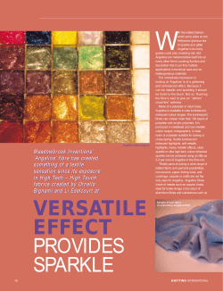

© Copyright 2026