
Technology Requirements for Mars Sample Return Using CO /Metal Powder
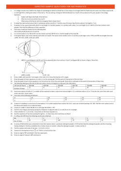
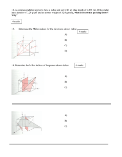
IAC.03.Q3.b06 Technology Requirements for Mars Sample Return Using CO2/Metal Powder Propellants Abdul M. Ismail, Owner & Chief Engineer INTERPLANETARY EXPEDITIONS, UK 54th International Astronautical Congress 29 Sept – 3 Oct 2003 / Bremen, Germany For permission to copy or republish, contact the International Astronautical Federation 3-5 rue Mario Nikis, 75015 Paris, France TECHNOLOGY REQUIREMENTS FOR MARS SAMPLE RETURN USING CO2/METAL POWDER PROPELLANTS Abdul M. Ismail, Owner & Chief Engineer INTERPLANETARY EXPEDITIONS 100 Greenhill Road, Mossley Hill Liverpool L18 7HN, England, UNITED KINGDOM Tel: +44 (0)151 280 8858 / Mob: +44 (0)79 76 63 19 46 [email protected] ABSTRACT Mars sample return missions, carrying a selection of rocks, regolith & compressed atmospheric gases, have been discussed in numerous research papers since the days of the Apollo landings but most concepts employ propulsion systems using conventional bi-propellant, composite solid propellants or cryogenic in-situ propellants. An alternative propellant combination consists of carbon dioxide (CO2), which constitutes about 95% of the Martian atmosphere, as the oxidiser & a metal fuel, such as magnesium, mined/collected & processed into powder. This paper reviews the constituents of the Martian environment & discusses various options to extract & process oxidisers & metal fuels for employment as a propellant. A basic propellant evaluation program (PEP) was used to ascertain specific impulse (Isp) for a wide variety of fuel & oxidiser combinations. This was followed by an appraisal of work on metal powder feed systems & injectors. The PEP values were entered into a standard model for sample return vehicles to allow a comparative assessment between various propellant combinations. Suggestions f or future work are presented in order to afford Mars mission planners an option to fund a viable alternative for Mars mobility & one that aspires to a roadmap of infrastructure development. water vapour was confirmed. Within ten years came the advent of ground based high resolution spectroscopy & spacecraft observations which provided evidence of CO, O2 & O3 as well as indications that the atmospheric pressure was more than 100 times lower then the pressure on Earth. The Viking landers expanded on the knowledge of atmospheric content by adding N 2, NO, Ne, Ar, Kr & Xe. Isotopic ratios in all gases, except for H, were also present. On board mass spectrometers on both Viking aeroshells detected molecular oxygen, atomic oxygen, carbon monoxide & nitric oxide in the upper atmosphere. The initial pressure readings from the first Viking lander indicated 7.65 millibar (mbar) but that figure decreased with time. The maximum readings were found to have reached 9 mbar at the first Viking site & 10 mbar at the second Viking site. Precise readings of the minor constituents were difficult to ascertain. This variation was attributed to the deposition & sublimation of CO2 which itself is dictated by the season. Table 2.1 shows the composition of the lower atmosphere of Mars, as detected & recorded by the Viking landers. The primary gases of interest to CO2/met al powder propulsion engineers will be the acquisition & storage of CO2 & N2; CO2 as the oxidiser component of the propellant & N2 as a possible pressurising gas. Ar is also of interest for the production of magnesium metal powder. 1.0 INTRODUCTION Establishing in-situ resource utilisation (ISRU), which includes propellant production, from Martian resources is seen as a prerequisite to any future long duration human expedition to the red planet. This paper introduces several key areas that will have to be addressed & mastered before a propulsion system using one type of propellant, i.e. CO2 as the oxidiser combined with a metal in the form of a powder as the fuel, can be realised. CO2 will have to be compressed over one thousand times from its ambient pressures to a level where it can be stored as a liquid. Metal powder, most probably magnesium, will have to be obtained, purified & converted into a pre-defined powder particle size. The various fuel & oxidiser combinations were identified & then fed into a PEP in order to determine Isp. In order to account for impurity of the ingredients, condensed phase effects & two-phase flow loss that can contribute to a serious degradation of performance, an efficiency of 80% was assumed. The issue of metal powder feed has been studied intermittently for over three decades & past research is reviewed. Four different sample return mission scenarios are presented & for each concept, a number of different propellant combinations are used to afford the reader & opportunity to compare conventional bi-propellant, in-situ & cryogenic propellants. The sample return mission presented is a simple “grab-&-go” & since mobility on Mars is limited to landing, sample procurement & take-off, the conventional bi-propellant proved to be superior in terms of mass savings. As the necessity for Mars mobility increases, so will the ?V requirement & hence the greater amount of conventional propellant from Earth. This is when the lower performing in-situ propellant will prove to be more superior. However, since an initial mission is intended to act as a technology demonstrator, then the selection of ISRU would have to be one that is comparable in trans Mars injection (TMI) mass to a conventional bi-propellant otherwise selecting the in-situ option would not be justifiable. A two stage Mars ascent vehicle (MAV) using ISRU for the lower stage shows that the total TMI mass of the sample return vehicle (SRV) would be no more than 65 kg heavier than an SRV using conventional bi-propellant for both stages of an MAV. This is an acceptable mass penalty for the test & evaluation of a system that could prove essential to the development of Mars mission infrastructure. Table 2.1: Composition of the Lower Martian Atmosphere Ranking Gas Abundance 1 CO2 95.32% 2 N2 2.7% 3 40 Ar 1.6% 4 O2 0.13% 5 CO 0.07% H 2O 0.03% 6 7 36+38 Ar 5.3ppm 8 Ne 2.5ppm 9 Kr 0.3ppm 10 Xe 0.08ppm 11 O3 0.04-0.3ppm 2.0 MARTIAN ENVIRONMENT 2.1 Atmospheric Properties Between 1947 & 1963, CO 2 was the only known constituent of the Martian atmosphere. Shortly afterwards, the presence of 1 2.2 Martian Geology & Su rface Mineralogy 3.0 CO2 PRODUCTION The data required to determine the mineralogical distribution over the Martian surface is being acquired by the Gamma Ray Spectrometer (GRS) on board the Mars Odyssey, which is presently mapping the surface of Mars. Initial indications show that most elements, apart from hydrogen, are more or less 1 evenly distributed on the surface of Mars . The most recent data available on chemical make-up of the Martian surface was obtained by Pathfinder’s Alpha Proton X-ray Spectrometer (APXS) instrument . Prior to Pathfinder, two sources of data existed on the surface chemistry of Mars; 1) Viking 1 & Viking 2 landers & 2) Shergottite-nakhlite-chassignite (SNC) meteorites. The Mars Global Surveyor (MGS) employed a Thermal Emission Spectrometer (TES), which afforded an opportunity to map certain surface areas of mineralogy, but not the entire face of Mars. Also, the TES instrument could only read mineralogical content of the top 10 microns of the surface & it was not able to provide sub-surface measurements. Thus, data obtained to date is not sufficient to present an accurate picture of the mineralogical distribution over the surface of Mars, but general geological knowledge does present an opportunity to gauge the types of minerals that can be found in specific locations. The focus of interest is with metals that are available, in-situ, that burn energetically with CO2 oxidiser. Previous studies on CO2/metal powder combustion have shown that the metal that exhibits the most promise is magnesium. Spectral signatures of igneous rock were partially hidden by layers of dust making it difficult for remote sensing & in-situ observations to gain an accurate reading. However, it is generally realised that basaltic lava covers the surface of Mars, which is rich in aluminium, Literally every ‘Martian’ in-situ oxidiser production method initially involves the collection & processing of CO2. The CO2 is acquired, filtered & then compressed to relevant temperatures & pressures where it is condensed into a liquid state. 3.1 Atmospheric Dust The Martian atmosphere contains minute dust particles ranging from 1 µm to 10 µm in diameter & such impurities can not only damage the compressor’s components or clog up the adsorption bed, but also lead to a degradation of performance by introducing impurities to the propellant formulation. A filter would ideally be connected to the intake of either the roughing pump or the adsorption bed. Bruckner et al. propose placing a pleated filter prior to the entrance of the intake in order to remove the larger dust particles & a membrane filter at the rear 4 end to remove the sub-micron particles . A method for removing the obstructing particles from the filter will also have to be devised otherwise the overall CO2 production system’s performance will diminish with time, more so if the landing site of CO2 plant experiences a dust devil or worse, a global dust storm (GDS). Ash at el., state that for their in-situ propellant production concept, it was estimated that for 140 days of operation, ~200 grams (60 cc) or ~1.43 grams per day, of dust will have to be removed from the atmospheric intake. The pressure drop through the atmospheric filter in the Martian 5 environment can be estimated by ; Q ∆P = 0.12 AF in millibar (3.1) where Q is the flow rate of the atmospheric fluid, litres/second & 2 A F is the surface area of the filter, m . 2 A filter with a surface area of 22 m will experience a pressure drop of ~0.4 mb. This pressure drop is relatively small & acceptable & coupled with the low atmospheric pressure, a filter with a throughput volume of 25 litres will result in a filter mass of 5 kg. 3.2 Adsorption Pumps When uncontaminated sources of fluids are required, the adsorption technique is an ideal process. Martian diurnal temperature fluctuations, on average 70 K, prove to be the ideal setting for a process that separates gases during the night & then rejuvenates during the day. The difference in loading, i.e. quantity of gas that can be stored in the adsorbent during the day & night, is close to the theoretical limit for specific adsorbents & the devices can be considered to operate at very high efficiencies. Adsorption pumps are generally regarded as comparable, if not superior, to single stage compressors 6 operating in the same environment but it is unlikely that a single stage compressor will be able to compress atmospheric CO2 from ambient pressures, 1000 times to 10 bar. Studies by Martin Marietta, now Lockheed Martin, showed that an activated carbon ‘sorption’ pump could theoretically adsorb ~40% of the mass of the sorbent material. Actual ex perimental figures show adsorption to equal between 5 to 15% of the sorbent mass. Therefore, it was determined that in order to produce 1 kg of CO2 per day, 2.5 kg of sorbent material would be required & that 50 W of power would be required to encourage out gassing 7 at high pressure . By employing solar arrays, the available power is dependant on the location of Mars’ orbit. At aphelion, -2 the solar flux is ~500 Wm but at perihelion, the solar flux is -2 ~730 Wm . The CO2 could then either be fed directly into a refrigerated storage tank. The ~5% trace gases such as nitrogen, argon etc. will not liquefy under the same environmental conditions as CO2 & could therefore be disposed off by occasional venting of the CO2 storage tank. However, nitrogen is another in-situ fluid that could prove to be of benefit with CO2/metal powder fuel engines in the form of a pressurant to feed the powder from the fuel tank to the chamber. But the minimal mass & therefore cost saving of transporting a small quantity of nitrogen for use in a propulsion system may not Figure 2.1: Spectral Imaging by TES (MGS) of Pyroxene Content on the Surface of Mars 2 calcium, iron, magnesium & silicon . It is also known that silicate minerals dominate the surface of Mars but due to their high magnesium content, olivine & pyroxenes are of most interest. Olivine, (Mg,Fe)2SiO4 comes in two variations; the forsterite series containing primarily magnesium & favalite, primarily Iron. Olivine content in the majority of the stony meteorites that have fallen to Earth contain on average 60 – 85% forsterite & the remainder, favalite. The spectral variation acquired from the TES is graphically illustrated in Figure 2.1. Figure 2.1A indicated the area examined during the pass of the MGS & Figure 2.1B shows the intensity of the pyroxene absorption. The magnesium rich minerals that future mining operations will find of interes t, in descending order, are enstatite Mg2 Si2O 6, bronzite (Mg,Fe)SiO3, hypersthene (Mg,Fe)SiO3, orthferrosilite FeSiO3 & clinopyroxenes which are in the form of pigeonite (Mg,Fe,Al)(Mg,Fe)Si 2O6, diopside CaMg(SiO3) 2 & augite (Ca,Na)(Mg,Fe,Al)(Si,Al)2O 6. Bronzite, one of the minerals containing a high quantity of magnesium, has been detected by the TES instrument during studies of the Hebes 3 Chasma & was found to constitute 7% of the reading. The remaining minerals detected during TES data acquisition were augite (45%), plagioclase feldspar (12%) & atmospheric dust (36%). From this type of information, there is enough data to provide a general indication on the mineralogical content of Martian regolith & rocks. 2 warrant the additional hardware required to acquire, process & store nitrogen. This trade off is only possible once the engine & its required propellant quantities have been sized. Argon is also a useful in-situ gas as it is often used instead of helium as a compressing gas for the production of magnesium metal powder & therefore could also be retained. One negative aspect of adsorption pumps is that the solid sorbent material is brittle & will have to be well protected during entry, landing & descent. Another problem that is envisaged with the operation of such a system is that with the increasing CO2 requirement, the adsorption bed will have to increase in size. The adsorbent mass will therefore take longer to cool down; decreasing productivity. A way around this problem would be to connect multiple smaller adsorption beds together but this will increase the inert mass. 3.3 Mechanical Roughing Pumps Figure 3.1: P-T Phase Diagram for CO2 Ash et al. state that in order to collect 1 kg of CO2 per day, 1.22 litres of atmosphere must be collected per second. They mention that laboratory vacuum pumps with a power consumption of ~700 W are capable of this throughput but the mass of such terrestrial devices are on the order of 50 kg. In addition to the task of raising pressures from 6.9 mb to ~10 bars, the pump’s compressor will also have to contend with overcoming the pressure drop through the filter, Equation 3.1. The quantity of stages for the compressor is dependant on; compression ratio, compressor materials, allowable tolerance levels & efficiency. As an initial assumption, each compressor stage is considered to be four times the volume of the rotor. ( Vr = 0.385 Qs1.5 ) 3.5 Mars Atmospheric Carbon Dioxide Freezer (MACDOF) 8 This system was proposed & designed by Zubrin et al . as a component of a larger plant to produce CO & LOX with the baseline NASA Johnson Space Center’s human mars mission as a reference, which calls for the production of 100 kg of CO2 per day. In principal, the MACDOF actively freezes CO2 from the atmosphere & produces on the order of 700 grams per day. It is less massive than a passive adsorption pump & yet, it has twice the capacity & 40% the storage capability. The experimental module was built out of steel whereas the adsorption pump was made from aluminium. It was determined that if the MACDOF was also made out of aluminium, then the mass would have been ¼ of the adsorption pump. An adsorption bed can store on the order of 10% of the adsorbent mass whereas the MACDOF is capable of storing 100% dry ice. Based on the logic of equal capacities, the freezer can store up to five times that of an adsorption bed. The freezer material is either diffuse copper or aluminium wool is much less dense than the adsorbent material. For example, copper wool is ~240 grams per litre which is over three times les s dense than activated carbon as a adsorbent material. The MACDOF is capable of acquiring a consignment of CO2 every five hours which, based on the use of solar arrays, affords an opportunity to collect CO2 twice per day, at best. The hours after sunrise & prior to sunset would reduce the solar flux so ten hours, or twice a day, may be somewhat of an over exaggeration. This system would more likely be able to produce CO2 1.5 times per day, which is still a 50% increase over passive or active adsorption pumps. Pioneer Astronautics takes the position that a nuclear reactor will power the in-situ propellant production (ISPP) system & therefore such a system will be able to operate at th rd least four times a day. So, with 1/5 the volume, 1/3 the th th interior density & 1/4 the cycle, this works out to be 1/60 the th mass of an adsorption pump & the shell is assumed to be 1/20 the mass of equivalent capacity. For of a low-cost sample return mission, the employment of a nuclear power plant is out of the question & solar arrays will be the most likely form of power generation. At worst case, the production rate of one times a th day relates to 1/15 the capacity of the adsorption pump; which is still a remarkable improvement. During these comparisons, the supporting hard ware for the MACDOF, such as refrigerators, heat sinks & heating units were not included. Also, the experiments were developed to test systems & were not optimised for mass & power consumption. As with terrestrial refrigerators, electric power is used to dispose of thermal energy from the freezer to ambient temperature. The refrigerator will also have to be thawed, to clear its contents following one production cycle. This could be performed via solar heating during the Martian day but active heating would increase the turn-around time. (3.2) where Qs is the volume flow rate at the stage inlet (litres/second) If the compressor’s volume consists of 75% solid material with an estimated density of 7.5 g/cc, the mass of the compressor will be on the order of 6 kg. One of the concerns about this system is the fact that involves the use of turbomachinery, i.e. rotating components, which raises issues regarding reliability. Still, it is the only device with heritage that could provide the required atmospheric throughput to produce quantities of CO2 in a short space of time. 3.4 CO2 Freezer/Collector An alternative concept is the CO2 freezer/collector, which was originally promoted as a component of a CH 4 manufacturing system. This proposed system could be adapted for a CO2collection-only scenario. Using a baseline average temperature as 210 K, Ash et al. calculated that ~80 W is required to cool down CO2 gas into the form of a solid, ~76 W of which is required for phase change. The power estimates were -1 deducted from the assumption that the wind speed is 0.1 ms & the known value for the latent heat of sublimation (598.6 kJ/kg). Other assumptions & operating conditions were as follows; the collector tube diameter is 1 cm; heat transfer coefficient for -2 -1 convection is between 1 & 8 Wm K; flow rates vary from 1 m -1 to 10 m ; full range of pressures & temperatures; radiation of -2 60 Wm & atmospheric gas is homogenous. The system uses a coolant, which passively freezes the CO2. The choice of coolant & its temperature as well as the collector’s density & thermal conductivity are strong factors that affect the collector’s performanc e. Since the concept was initially designed to produce methane, the researchers simply used a small quantity of the methane they produced to feed through the collector’s coils. The CO2 could then be scraped off the cooling coil, compressed to a pressure of ~70 bars fed into a storage tank, where the CO2 is stored in the form of a solid. During the CO 2 frost extraction process, the introduction of heat could raise the temperature to ~218°K where the frost would liquefy & subsequently be redirected to a liquid CO 2 tank. Approximately 40 W of power would be required to heat the frost to liquefaction temperatures. 4.0 METAL POWDER PRODUCTION The most likely metal fuel for use in CO2 engines is magnesium so the focus of work in this section is on the production of this element. Magnesium is estimated as being 4 to 5% content of the Martian regolith & rocks, but to date, there is no evidence of 3 large concentrations like those found in natural deposits on Earth. Based on current knowledge, magnesium can only be acquired for processing in two ways on Mars. 1. 2. sudden expansion causes a cooling effect. This, coupled with the collision of cool inert gas, causes instantaneous solidification of the met al. Nitrogen, the second most abundant gas in the Martian atmosphere, reacts with molten magnesium thus magnesium powder producers 9 tend to use either helium or argon as the compressor gas, the latter of which is available in-situ, albeit in small quantities. Helium delivers a solidification rate of one order of magnitude over argon, but is it not available insitu. Subsonic gas atomisation achieves very low efficiencies & therefore results in utilising much more inert gas but this problem could be addressed by re-circulating the gas. A problem regularly experienced with gas atomisation is satellite accumulation. This is where, during the powder production process, small fine particles become attached to the larger, coarser particles. Satellite accumulation reduces packing density by several percent. Particle sizes from between 20 to 400 microns can be obtained from this method of particle production. The nozzle dimensions, temperature & rate of flow of the molten metal & compressing gas are all contributing factors to the resultant particle size. Ideally, this system is designed for temperatures less than 973.15 K, due to the limited longevity of the molten metal orifice. Higher temperatures can be obtained by using advanced materials or by subjecting the orifice to cooling. The oxide content of metals particles produced by atomisation are as low as 0.2 to 0.3 %. This is attributed to the rapid cooling & possible formation of a thin oxide layer than prevents additional oxidation. Collection & processing of rock s or Collection & processing of regolith Rocks containing the desired metal, in our case magnesium, are referred to as ‘ores’ & metals are usually found in the form of mineral compounds; either sulphides or oxides. The process used to produce terrestrial magnesium from magnesite is probably the closest type of technology that could be employed for extracting magnesium from ores for subsequent processing into magnesium metal powder on the Martian surface. In essence, the process can be split up in to three sub-categories; a) Prior to mining: This requires a detailed analysis of the surface features in order to determine mineralogical concentrations of ores with high content magnesium, such as bronzite. Surface sampling will then, in the case for Mars, be performed by either manned or unmanned methods. The samples will have to be examined for quality before the intricate process of mining the ores takes place. b) Mining proper: When the quality of the magnesium has determined, the design of the site for excavation is established & the pertinent engineering equipment is brought in to procure the ores. Continuous geological sampling & assessment of the process will be required to ensure quality of the product. c) Subsequent to mining: Once the ores have been obtained, they are crushed into powder form & then separated for magnesium rich minerals. This is a process known as beneficiation. An alternative methodology to the first part of beneficiation is to simply collect the fines, or regolith, on the Martian surface, which have already been crushed by nature in readiness for collection. This approach would be favourable due to the fact that it would alleviate the energy requirements to crush & produce fine powder. The process of smelting then takes place, i.e., where the minerals are fed into a furnace & heated to melting temperatures. Although the minerals will contain several elements, the melting point of magnesium will determine the point where the metal can be separated from the ‘slag’ & impurities. The final process, known as refining, is used to remove impurities from the metal, resulting in a near-pure product. 4.1.2 Removal of Dust Once the powder has been produced, it is fed through a series of sieves in order to group the required sizes for metal powder fuel. By slowly feeding the metal powders into a container with a vertically rising current, dust particles (impurities) that have settling velocities less than the velocity of the current will be carried up & are subsequently removed from the container. The velocity of the vertical current can be adjusted in order to afford the disturbance required to separate agglomerates & any dust that may be trapped between them. 4.1.3 Production of Alloy Powders The problem experienced with the production of alloys is that due to the difference in the density of constituent metals, homogeneous powders are not produced. The first step toward the production of alloy powders is to adjust the apparent densities of the alloy’s components, in this case magnesium & aluminium. Once the percentage of mixtures is known, the less dense metal (magnesium) content is increased & the higher density material (aluminium) is decreased. The metals are then heat treated & then the alloy is formed by diffusion. 4.1 Preparation of Metal Powders There are several ways of producing metal powders; 1. 2. 3. 4. 5. Reduction of oxides & other compounds Electrolysis Atomisation Mechanical comminution (crushing, milling etc.) Coldstream process For terrestrial applications, atomisation & reduction techniques are used for high tonnage production whereas the other methods are used for small quantities of specialist powders. Atomisation, however, is the only feasible terrestrial technique that could be employed for metal powder production on the Martian surface. 4.1.4 Safety Issues Dust explosions are probably the main threat to the production of metal powder. Such incidents can occur in any environment with oxygen cont ent where; 1. 2. 4.1.1 Atomisation To avoid having to reheat the metal to its melting point, this technique can be introduced at the end of the refining process since the metal will already be in a molten state where it is drop fed though a small orifice or apex, hence producing a stream of molten metal. The molten metal is then broken up by a jet compressed inert gas is directed towards it at an impingement angle, up to 90°. The compressed gas leaves the nozzle at high velocity but slows down during its flight path to the apex. This attenuation is increased the further the compressed gas has to travel & results in decreasing the effectiv eness of being able to break up the molten stream. When the molten metal stream leaves the mouth of the orifice the The dust concentration exceeds an explosive limit The presence of an ignition source with sufficient energy A pressure rise can, in some part, be attributed to a sudden increase in erratic atmospheric flow. In relatively steady conditions, flame speed in a dust cloud can be several metres per second whereas in a turbulent environment, the flame speed can rise to several hundreds of metres per second. If the environmental temperature within the enclosed area is high enough then friction between the metal particles could cause an arc & ignite the powder, resulting in a controlled burn & possible explosion. The density of the flow of metal particles during metal powder production must therefore be kept to a 4 Table 5.1: Propellant Combinations Examined & Specific Impulse Obtained (in seconds) ISRU Metal Fuels Mg Al Si Ca Ti Mn Fe K Na Cr Mg/Al Other potential ISRU Fuels 13.79 bar 34.47 bar CO2 215.7 224.9 LOX 263.2 277.2 13.79 bar CO Non-ISRU Metal Fuels 34.47 bar CO2 - - LOX 256.9 267 Zr 13.79 bar 34.47 bar CO2 193.9 201.4 LOX 232.9 244 Other non-ISRU Fuels (Hydrides) 13.79 bar BeH 2 34.47 bar CO2 331.2 346 LOX 439.6 460.2 CO2 228.6 238.7 CO2 - - CO2 213.7 240.7 CO2 239.7 252.1 LOX 275.5 290.3 LOX 443.6 454.8 LOX 315.3 330.7 LOX 328.8 344.8 CO2 200 208.2 CO2 - 120.4 CO2 257.3 268.7 CO2 - - LOX 246.9 260.4 LOX 341.4 354 LOX 316.7 330.9 LOX - - CO2 - - CO2 - - CO2 192.1 201.8 CO2 283.1 293 LOX - - LOX - - LOX 298.6 313.9 LOX 369.6 386.1 CO2 180.1 101.4 CO2 - - CO2 291.1 303.1 LOX 241.9 254.7 LOX - 346.7 LOX 380.3 395.9 CO2 - - CO2 - - CO2 263.2 273.2 LOX - - LOX - - LOX 355.1 371.1 CO2 99.5 103.8 CO2 162.7 169.1 LOX 178.5 184.3 LOX 315.5 327.5 CO2 104.6 109.4 CO2 - - LOX 151.3 167.4 LOX - - CO2 - 158.9 LOX 184.9 193.2 CO2 125.8 131.4 LOX 211.1 220.8 CO2 225.2 234.1 LOX - - LH 2 CH 4 C 2H 6 C 3H 8 C 4H 10 CH 3OH N 2H 2 Li Be B MgH 2 SiH4 Al(BH 4)3 B2H 6 B5H 9 minimum & the entire procedure of powder production should be manufactured either in a partial vacuum or in the presence of a non-reactive inert gas. Having the ability to accurately predict the conditions where a flame can propagate within a confined space may prove to be of value to a metal powder fuel engine. An increase in apparent density of the dust cloud plus a rapid circulation of fluid flow has proven to increase the burn rate of the metal powder fuel. From this, the deduction is made that the fuel should be injected in a way that maximises turbulence within the thrust chamber. Increasing the metal powder density towards the injection end could, hypothetically, increase particle burn rate resulting in a reduction of two-phase flow loss & incomplete combustion. diborane, pentaborane, methane, ethane, butane, propane & methanol. The majority of previous “Martian” in-situ propellant studies focussed on LCO/LO2 or LOX/LCH4 engine concept utilising ingredients from the atmosphere alone & in the case of the latter; a small amount of LH 2, brought from Earth, would be required to produce LCH4. The LCH4 option provides a very reasonable performance & the storage temperature is a lot more manageable than LH 2. Thermoc hemistry values for these concepts were also calculated. 5.1 Computer Code The Propellant Evaluation Program (PEP) used was an 12 adaptation of the US Navy’s PEP code & is available in the public domain. Shafirovich et al. have performed detailed studies of C O2 reactions with selected metals plus their hydrides using accurate code that includes the effects of twophase flow loss & incomplete combustion, which the PEP program did not consider. A more sophisticated code written by 13,14 Gordon & McBride from NASA Glenn Research Centre is available by formal request only, but this code was not available for use during the course of the study. Since the intention in this study was to address every possible in-situ propellant combination & LOX/metal powder reactions , the basic code was used to maintain consistency. It is, however, recommended that Gordon & McBride’s program is used for a more detailed analysis in future work on CO2/metal powder engines. 5.0 PROPELLANT COMBINATION S Based on research from section 2, numerous propellant combinations were identified employing oxidisers derived from the Martian atmosphere & combined with a selection of metal fuels. The two oxidisers were CO2 & cryogenic (liquid) oxygen (LOX), the latter of which was included for several reasons. The first is because the production of LOX is a logical extension of LCO2 production & although more complex to generate in terms of manufacture & storage, the combination of LOX with metal fuels delivers higher values of specific impulse & affords the opportunity to address the issue of a lunar soil propellant (LSP) as well. The difference of course being that the LOX on Mars is extracted from the Martian atmosphere following the production of CO2 whereas on the lunar surface, it would have to be extracted from the metal oxides. The metals available in quantity on Martian surface are magnesium, aluminium, silicon, titanium, manganese, iron, potassium, sodium, chromium & magnalium. Non-ISRU metals & their hydrides that are known to react well with CO2 & LOX were also examined. These fuels 10 were zirconium, lithium, beryllium & boron . Calcium & silane were not available as propellant ingredients in the software 11 used & were not examined. The other chemicals were bery llium hydride, magnesium hydride, aluminium borohydride, 5.2 Propellant Combinations Table 5.1 outlines the results of propellant combinations that were addressed in this study for 200 psi (13.79 bar) & 500 psi (34.47 bar) chamber pressures, respectively. Previous studies on theoretical specific impulse based on increasing chamber pressure & expansion ratio with a Martian ambient exit pressure of 6.9 mb showed little improvement in performance for the added mass required to pressurise the propellant tank. 5 Initially, the metal powder fuels were selected for their availability on the Martian surface & others for their performance when combined with CO2. However, it is unlikely that a number of these fuels will be employed in a propellant combination due to undesirable pre-combustion & postcombustion properties. Magnesium has time & again been able to combust in CO2 environments, either with single particle experiments or demonstrator engine tests. It is also storable, non-toxic plus it can be ignited at relatively low temperatures & exhibits a high rate of combustion in the vapour phase. concept is the energy required to produce molten liquid metal & sustain the metal in that chemical state, prior to injection. It is also worthy to note that even though the design is intended to circumvent the problem of metal powder feed by giving it liquid form, this does not entail that the engine will work in the same way as a conventional liquid propulsion system. Goroshin, Higgins & Lee note that the boiling point of magnesium (1373.15 K) is considerably higher than conventional liquids 15 (623.15 K) , which imply that the combustion chamber will have to be larger to cater for the longer combustion process. 5.4 Impure Gases & Powders 6.1.2 Hybrid Engine Here, impurity is not just related to physical impurities such as contaminants within the oxidiser or tainted quality of the metal powder. Impurities are also recognised as any chemical other than the chosen oxidiser & the fuel. This implies that the carrier fluid that is employed to transport the metal powder particles from the storage tank to the combustion chamber is also referred to as a contaminant because, depending on the fluid, it could contribute to a degradation of performance. If one were to assume that during the acquisition & processing of CO2, the trace gases were not removed, then this would result in an automatic reduction of ~5% of the CO2’s contribution to the propellant formulation. During CO2/magnesium metal powder rocket engine tests at Wickman Spacecraft & Propulsion Company (WSPC) in 1998, a series of gases were used as the carrier fluid; hydrogen, helium & nitrogen. The selection of carrier fluid for engine tests during WSPC experiments were selected not just for storage for considerations but also for availability of Mars. A 7% weight fraction of hydrogen was found to deliver over 25% increase in specific impulse but it is less dense than the other fluid that leads to the requirement of larger storage tanks for the sam e volume of other gases. Nitrogen constitutes ~2.7% of the Martian atmosphere but is a fluid that reacts with molten magnesium. However, from all of the engine tests performed at WSPC, not one experienced flashback. This leads on to the possibility of using CO2 as the metal powder carrier gas as well as acting as the oxidiser. Impurity distribution within the powder is an important contributory factor towards not just the combustion process, which results in degradation of performance, but also to the longevity of the engine. One must keep in mind that reducing the purity of the metal powder from 99.5% by several percent could increase the lifetime of the engine feed lines & injectors. This is because the more pure the powder, the greater capacity for abrasion & wear within the engine’s feed tubes. This configuration is probably the most simplistic, in terms of technological know-how. If one were to assume that the metal powder fuel were taken from Earth to Mars in a predefined mould within the combustion chamber, similar to composite rocket propellant in solid rocket boosters, then only CO2 oxidiser will require acquisition, storage, feeding & injection. The risk factor associated with this configuration is therefore minimised with the omission of one (fuel) tank & the associated feed lines. As with all hybrid concepts, the system can be throttled by altering the oxidiser flow rate & shut down during operation in case of an emergency. The fuel grain can take two forms; 5.3 Chemical Properties 6.0 PROPELLANT FEED ISSUES 1. The metal could be premixed with a hydroxy terminated polybutadiene (HTPB) binder & set with a curing agent to maintain integrity. Adding HTPB will lower the percentage fuel content & will reduce specific impulse. In fact, tests at WSPC proved this concept ineffective since the propellant failed to ignite so the addition of an energetic plasticiser would be necessary to afford ignition & a sustained burn. 2. The metal powder could be pneumatically pressed into a predefined shape. There are however, several inherent problems associated with this concept. Studies on LOX/aluminium engines have shown that the rate of regression of the metal could be difficult 16 to control . The aluminium fuel grain would act as a heat sink due to its high conductive properties & this would result in melting more metal than required which could result in over pressurisation leading to engine failure. Magnesium has a lower melting point & therefore would be an even greater concern. 6.1.3 Monopropellant Engine The type of propellant feed is entirely dependant on the configuration of the engine. There are several possible schematics for CO2/metal propellant tanks & feed systems, & not all of t hem use metal fuel in powder form. This process employs a met hod where the metal powder fuel is premixed & stabilised in LCO2 to form a ‘monopropellant’. Only one tank, plus its associated feed lines will be required. Experimental studies by WSPC et al. in the 1990’s showed that energetic propellant combinations suc h as LOX could be safely mixed with 17 metal powder fuels , such as aluminium, or kerosene (RP-1). Acceleration forces during launch would ‘force’ the heavier elements within the propellant solution in an opposing motion to the acceleration, i.e. towards the rocket engine end of the propellant tank. Without an adequate device to continually mix the monopropellant, the initial monopropellant that enters the combustion chamber will be very fuel rich & the last quantity of monopropellant leaving the tank will probably be close to 100% liquid oxidiser. Another option would entail the use of a minimal amount of liquid oxidiser, which is stored separately, sufficient to fluidise the metal fuel to provide a flowing motion. The propellant would be stored as a fuel rich monopropellant & the remaining oxidiser would be injected into the combustion chamber, under a different feed mechanism hence acting as a regulator for the oxidiser/fuel ratio. The latter concept resembles the ‘bipropellant’ engine but has one major difference. This option uses the propellant’s oxidiser to provide the flow of propellant & is in liquid form whereas the concept 6.1 Fuel System 6.1.1 Liquid Metal Injection The principal of this design is to liquefy the metal powder prior to transferring & injecting the fuel into the combustion chamber. The advantage of such a system would be that the fuel could be atomised to droplet sizes smaller than the metal particles that one would find in a solid rocket motor. This would result in a faster burn rate & subsequent combustion, which would minimise or eliminate two-phase flow losses & incomplete combustion hence contribute to an overall increase of efficiency of the propulsion system. Previous analysis of chamber cooling shows that a pump fed system will have to be employed for this task. Due to the high temperatures envisaged in the metal fuel feed system, plus the pertinent cooling, any residual liquid metal fuel may be subject to solidification in the feed pipes & injector interface. But, probably the greatest technological challenge associated with this 6 described in Section 6.1.5 uses a benign carrier gas. It was shown that for monopropellant formulations, metal particles less than 60 microns tended to bundle together whereas this tendency was all but eliminated for sizes of 100 microns & above. Since the metal powder is premixed with the oxidiser, it is unlikely that regenerative cooling will be employed due to safety reasons. If regenerative cooling were required, then one way would be to have a separate tank of LCO2 to cool temperature critical components & then, prior to injection, be used to adjust the mixture of the monopropellant to a stoichiometric value. This proposal was addr essed for a 18 LOX/aluminium powder ‘Lunar Soil Propellant’ concept . The metal particles would have a predefined size to ensure total combustion & will therefore not have to be atomised. Clogging in the feed lines & injector will be a major technological hurdle & is one that will have to be addressed if such a concept is to see the light of day. The concepts reviewed thus far assume that the CO2 will be in liquid form. Of course, for reasons of density & therefore, storage, this would be beneficial. It is more than likely that the LCO2 will convert to a gaseous state, not long after leaving the storage tank & could therefore be used to pressurise the metal powder tank & assist the flow of powder from the tank. metal powder fuel plus the carrier fluid will be taken to Mars from Earth, but if we were to assume that we should only use resources available on Mars, then that would automatically disqualify helium as a potential candidate. Nitrogen is the most suitable candidate due to its benign property & storability. Hydrogen has been found to exist in the subsurface of the Mars but this has not yet been confirmed, in-situ. Linne & Meyer documented one not -soreassuring observation regarding this method of feeding powder. Inspections showed that with the pressurising of the metal powder within the fuel tank, occasional air pockets formed which caused ‘bubbling’. This resulted in a variation in feed pressure resulting in inconsistent flow. Although Wickman made no such observations during experimental test firings, one should not rule out that this could be a possible explanation or a contributing factor for the fluctuating chamber pressure observed in the results of the engine tests. 6.1.6 Pump fed Pressure fed propulsion systems require thick wall propellant tanks in order to withstand the high feed pressures & so the principal of this concept is to reduce structural mass of the propulsion system. The principal requirement would be to ensure high efficiency to justify the employment of such a system. Tamura et al. performed subscale experiments in the early 1970’s on metal powder turbojets & they found that additional research in this area was not advisable due to clogging in 20 the blades . Wickman et al. came to the same conclusion in the late 1990’s when working on a concept to propel Mars aircraft by a turbojet using CO2 & magnesium metal powder propellant. 6.1.4 Pneumatic Feed This was the preferred method of powder feed by Loftus et al. & subsequently by Linne & Meyer. Meyer used a 19 fuel tank that was a modified hydraulic cylinder . With the fuel tank valve turned off, a small amount (~1% of fuel component mass) of carrier or fluidising gas such as nitrogen was introduced into the fuel tank to fluidise the metal powder fuel. The pneumatic piston is compressed slightly so when the valve is opened, the carrier fluid & metal powder will flow into the feed lines & at the same time the pneumatic piston ensures positive feed pressure on the powder. The use of a pneumatic piston in conjunction with a small quantity of fluidising gas reduces the amount of carrier gas requirement by ~5%. Throttling as well as engine shutdown & restarts are possible with this configuration but the feed lines will have to be purged with an inert gas prior to any restart. The pneumatic feed system is a separate component from the pump or pressure fed oxidiser & therefore adds inert mass to the system as well as additional power for its operation. 6.2 Metal Powder Feed Issues Pneumatic & pressure fed concepts mentioned above employ a non-standard propulsion technology component; the method of transporting metal powder from the fuel tank into the combustion chamber. The feed of metal powder or the flow rate is a function of the method of storage, injection & combustion. It is also dictated by the particle size distribution & shape but also the properties of the metal powder such as coefficient of friction & in some cases, by the metal’s electrostatic & magnetic characteristics. Adsorbed moisture can also be a contributory factor associated with the inhibition of free flowing particles. 6.1.5 Pressure Feed 6.2.1 Fuel Tank This was the method used by WSPC during test firing of a ‘Martian’ in-situ propulsion system under a Phase II SBIR contract for NASA Marshall Spaceflight Center/Jet Propulsion Laboratory. A number of carrier fluids were examined, including gases & liquids. The criteria for tradeoff for the carrier fluid selection were as follows; 1. 2. 3. 4. 5. The fuel tank design will differ depending on the chosen method of metal powder feed. Hybrid concepts will employ standard liquid feed systems whereas liquid metal & monopropellant concepts, although unique in their own way, will involve adaptations of present liquid engine feed systems & will not be addressed here. Linne & Meyer proposed four methods of metal powder feed; Evaporation rate Compatibility with magnesium Low molecular weight Influence on combustion temperature Influence on specific impulse 1. 2. 3. 4. Liquids wer e found to resemble the problems experienced with the monopropellant configuration, i.e. clogging etc. so attention was focussed on the gases. Two categories of fluidising gas exist; those that improve performance & those that tend not to react with the metal fuel. The three gases that were examined were hydrogen, helium & nitrogen. All three improved the performance (specific impulse) substantially, nitrogen was eventually chosen as the carrier fluid for three reasons. 1) gases such as hydrogen & helium could afford ignition in the feed lines, 2) due to the low density of both hydrogen & helium, these fluids would require storage in cryogenic liquid form & additional system mass is not warranted & 3) the eventual objective is to use readily available resources for 100% in-situ propulsion systems which leaves the choice of CO2, nitrogen or argon. Initially, it is envisaged that the Fluidised bed Screw/worm feed Fluidised hopper Fluidised piston The fluidised bed is probably the simplest & it was the method used by WSPC in all ‘Martian’ In-Situ engine experiments. No known problem regarding clogging was encountered but this is probably due to the fact that the standard liquid injectors were not used. A screw/worm feed uses a helical system to transport the powder from one location to another but the feed rate is extremely slow. The fluidised hoppe r is similar to the fluidised bed except it draws the metal powder fuel from the centre of the tank. The fluidised piston is another term for the pneumatic piston feed method. 7 6.2.2 Injectors Due to the limited burn time plus combustion fluctuation experienced, it was not possible to obtain any detailed data to analyse injector performance. A staged combustor 23 or pre-burner, as proposed by Goroshin et al ., could enhance the combustion process but experimentation will be required to validate this suggestion. An additional method for improving combustion would be to apply reverse flow, which is where the fuel &/or oxidiser are injected from the nozzle end towards the front end of the combustion chamber, at very high pressures. The latter method would have to fight against the force of the MAV’s gravitational acceleration; an option which would necessitate increased pressure for the carrier gas & component mass for pressurised tanks & feed lines, which will have to engineered to cater for the higher pressure requirements. Three types of injector designs have been considered. Loftus et al. used two concepts, both of which were modelled on liquid engine technologies. WSPC introduced the third method, the design of which was based on a powder manufacturing technique using a compressed gas. For all three designs, cold flow tests provided the necessary feedback for injector calibration & the quantity of inert gas required to fluidise & transport the metal powder from the fuel tank to the chamber. The results established metal powder flow rates to obtain optimum conditions for engine operation. Once the injectors had been calibrated, the motion of live firings took place to determine performance. It was found that fluctuation in pressure occurred for ±88% in the experiments of Loftus et al. for AP/Al propellants, WSPC, +15.6% / -8.6% for CO2/Mg propellants & Meyer, +30% / -27% for GOX/Al propellants. Loftus & his team at Bell Aerospace introduced methane as a carrier fluid & pressure oscillations decreased from ±88% to ±12%. The pressure variance was a result of low flame temperature experienced during the combustion process. It was determined that with a constant feed pressure, the initial low chamber pressure allowed an excess amount of metal powder into the chamber, which was followed by a large pressure spike above mean chamber pressure, due to ‘over’ combustion, which inhibited the entry of additional powder that was being fed at a predefined feed pressure causing a pressure drop below mean chamber pressure. The result was a rapid fluctuation of pressure, which was visible when observing the video footage of the engine tests. The variation of pressure during combustion was confirmed after examining the readings acquired from the pressure transducers. In all cases, the use of small particles or the introduction of a reactive fluidising gas afforded near-smooth combustion, albeit the former did prove detrimental to free particle flow & showed a tendency to want to clog in the injector manifold. Besides serving as a device to mix the fuel & the oxidiser, the metal powder injector required no ni tricate design for atomising the metal particles since the size & shape was predefined for flow characteristics, burn rate & subsequent combustion chamber sizing. The coaxial & 21 premix injectors used by Loftus et al . are shown in Figure 6.1. The fuel & ox idiser feed lines on the coaxial injectors simply converge towards the mouth (orifice) of the injector, i.e. prior to the injector meeting the combustion chamber face plate. The fuel & oxidiser feed lines on the premix injector introduces a miniature throat & nozzle, which encourages premixing of the fuel & oxidiser prior to injection. These injectors were designed for AP & aluminium powder but could be used to minimise the two-phase flow experienced between the carrier fluid & the metal particles. Feed pressure drops & pressure oscillations for the coaxial injector were high. This was attributed to the relative uneven mix of fuel & oxidiser & irregular combustion. However, the manifold in the premix injector introduced flow paths of changing internal diamet ers, which encouraged pressure variations. This resulted in a reduced flow rate & a larger pressure drop 22 then experienced with the coaxial injector. Akiba et al . found that the carrier gas flow rate was directly proportional to the orifice pressure drop; Carrier m& Gas ∝ ∆P Figure 6.1: Coaxial & Premix Powder Injectors 6.3 Summary of Metal Particle Fuel The advantages of metal powders are that the systems can be easily throttled as well as stopped & restarted, if required. The mass flow rates are insensitive to extreme environmental conditions, which for case of Mars will prove advantageous. The particle sizes are induced by the method of packing & combustion. As mentioned earlier, combustion efficiency increases as the particle sizes decrease but packing density has been proven to have a greater result with a mixture of two sizes, one large & the other small. However, sufficient breathing space must exist between the particles if one is to entrain fluidising gas into the powder fuel tank. If incorrect sizes of metal powder are chosen, then there is a danger of packing the metal powder so tight, that it will exhibit flour like tendencies & stick together which is thought to be caused by electrostatic & adhesive forces. Magnesium combustion temperature will also have a hand to play in the selection of fuel particle sizing but the combustion temperature is also a function of the particle resident time within the combustion chamber. It is therefore safe to conclude that the combustion chamber parameters will have a direct effect on the choice of particle size & vice versa. Suffice to say, past researchers were either content with -325 mesh or 44 micron (Wickman), a 70/30 mix of 30µ/3µ (Loftus et al.) or >10 µm (Meyer), with all researchers agreeing on the particle configuration as being spherical in nature. (8.1) & the gas flow rate was directly proportional to the factor of 0.7 of the orifice pressure drop; m& particle ≈∝ ∆P0.7 (8.2) It should be stated that every known metal powder engine test has never operated more than 5 seconds in duration. Loftus et al.’s engines operated for 2 seconds, Akiba’s for 5 seconds, Linne & Meyer’s for ~1 seconds & WSPC for 8 seconds but with ~3.5 seconds of sustained combustion. 7.0 SAMPLE RETURN MISSION SCENARIOS In the report of which this paper is based upon, four different mission scenarios are addressed & for each scenario, a large 8 selection of different propellant combinations employing cryogenic, storable liquid, composite solid & in-situ (CO2/metal powder) were examined. Only a summary of results is presented in this paper. In-situ propulsion systems using CO2/metal powder propellants were not capable of achieving Mars orbit with a single stage MAV, at least not with a realistic & justifiable mass. As a result, two stage to Mars orbit (TSMO) options were employed for all propellant combinations in order to provide a comparative assessment between in-situ & conventional technologies. LCH4/LOX calculations were performed with an assumption that 75% of this propellant is manufactured on Mars where the remaining 25% LH 2, required to produce LCH4, is brought from Earth. A factor that was omitted in the LCH4/LOX calculations was the mass of the system required to manufacture the LCH4 & LOX. The masses shown in Table 7.1 include the entire sample return vehicle (SRV) which, when broken down, comprises of; TMI propellant, Mars descent vehicle (MDV), Earth return vehicle (ERV) & propellant for trans Earth injection (TEI). The MDV houses the lander, CO2 production equipment & the MAV. The ERV & propellant for TEI is only applicable for the MOR option & nd employs conventional bi-propellant. The ∆V for the upper (2 ) & st lower (1 ) stage of the MAV was optimised depending on the propellant combinations used. This distribution is indicated in Table 7.1 as a percentage next to the mass. The inert mass fraction f(inert) was dependent on whether a conventional propulsion or in-situ system in employed, the values of which can range from 10 to 12 % for the former & 20 % for the latter. In addition, since the PEP used did not include a facility to calculate two phase flow loss & incomplete combustion, CO2/metal powder propellants were assumed to have an efficiency of 80%. provide the necessary ?V burn for TEI without an MOR. The total TEI ?V for a type III or type IV trajectory equals 5.7 km/s where TEI = 2.5 km/s, mid-course corrections (MCC) = 0.3 km/s, Earth orbit insertion (EOI) = 2.5 km/s & attitude/orbital control (AOC) = 0.4 km/s. If a type II launch opportunity exists for Earth return, then the figures will be more on the order of TEI ˜ 4.5 km/s, MCC = 0.3 km/s & AOC = 0.9 km/s. The type II Earth return trajectory would not include sufficient propellant for EOI or to ensure the use of a medium sized launch vehicle & will have to either enter directly into the Earth’s atmosphere or aerobrake for a rendezvous with the US space transportation system (STS) or the internationa l space station (ISS). An assumption is made that once the sample is launched into a lower Mars orbit (LMO), the ERV will acquire it immediately. Since the objective of this unmanned sample return mission is to keep costs down to a bear minimum, yet reside on the surface of Mars for sufficient time to manufacture enough CO2 oxidiser for Mars ascent & collect the pertinent samples, type IV missions will be the most energy efficient & therefore the most appropriate. The next available opportunity for a type I V mission st is 21 November 2006 & the trajectory will take the SRV on a 2 year & 2 month flight to Mars. Upon arrival on the Martian surface, the earliest possibility that one can depart Mars for a th TEI is 7 July 2009 on a type II trajectory for an arrival on Earth st on 21 May 2010. The total stay time on the Martian surface will be approximately 173 days. An alternative scenario would entail th a type II trajectory departure on the 7 August 2005, arriving at th Mars on the 19 July 2006. Earth return on a ty pe II trajectory st th will depart Mars on 21 July 2007 & will arrive at Earth on 29 April 2008 resulting in a residency time on the Martian surface for ~365 days. This option, however, will only be possible with aerobraking both at Mars & at Earth. The OOE with aerobrake option affords the opportunity to arrive at Mars, enter into an LMO & then agree on a landing site with prior consultation with planetary geologists. Even though a two stage MAV using insitu propulsion systems for both the upper & lower stages is achievable, the fact remains that it will be difficult to justify the selection of such a system based solely on the logic on the development of infrastructure. An in-situ propellant option for both stages on the OOE (aerobrake)/MOR scenario is over 8 times the mass of a system that uses conventional liquid bipropellants for both stages in the same scenario. However, st introducing a CO2/magnesium lower (1 ) stage with a nd conventional liquid bi-propellant upper (2 ) stage does afford a comparable perf ormance with the former having a TMI mass, of only 65 kg more & could provide the justification to develop infrastructure while increasing the chance to succeed in a sample return mission using ISRU. The four possible mission options are; • • • • Direct Mars Entry (DME) / Direct Earth Return (DER) Out-of -Orbit Entry (OOE) / Direct Earth Return (DER) Direct Mars Entry (DME) / Mars Orbit Rendezvous (MOR) Out-of -Orbit Entry (OOE) / Mars Orbit Rendezvous (MOR) There are two possibilities of returning samples to Earth from Mars. The first is MOR, which employs an ERV & is used to capture the sample that is launched into Mars orbit by a two stage MAV. The ERV then initiates a propulsive burn that brings the sample back to Earth. The second option is DER where the sample container is launched directly to Earth from the surface nd of Mars where the upper (2 ) stage of the MAV will have to Table 7. 1: Sample Return Vehicle Wet Mass (from LEO), shown in kg 2nd Stage LOX/LCH4 CO2/Magnesium CO2/Aluminium N2O4/(50% N2H4 – 50% UDMH) N2O4/(50% N2H4 – 50% UDMH) 1st Stage LOX/LCH4 CO2/Magnesium CO2/Aluminium CO2/Magnesium N2O4/(50% N2H4 – 50% UDMH) Direct Mars Entry/Direct Earth Return (DME/DER) Out-of-Orbit Entry/Direct Earth Return (OOE/DER) 50% 582.44 - 50% Propulsive Capture - - 877.65 50% - Direct Mars Entry/Mars Orbit Rendezvous (DME/MOR) Out-of-Orbit Entry/Mars Orbit Rendezvous (OOE/MOR) - Aerobrake 1338.02 60% 40% 13648.41 50% 50% 9 50% 50% - - - - - 1747.16 60% 40% - - 5891.02 3222.72 - - 70% - 30% - - 17704.44 - - - - - - - - - Propulsive Capture - 50% - - - - - 50% 2139.48 30% - - 50% 70% 11754.80 - - Aerobrake - 80% 20% - 1683.04 60% 40% option to transport food products such as flour, sugar, coffee powder & salt from production to packing. This is considered the safest way & preferred method of transporting the powder since dust explosions can be avoided. It also has the added benefit of avoiding contamination since the powder is transported in an enclosed environment. However, it is does have a tendency of damaging the food product & is rarely used when compared to other methods. A possibility therefore presents itself to team up with terrestrial industry for mutual benefit. A solution to the feed of metal powder may lie with the decades of experience from feeding powders in the catering industry. Any success with the design of metal powder rocket engine feed systems could then be spun -off for the benefit increasing safety in terrestrial industry. 8.0 RECOMMENDATIONS FOR FUTURE WORK 8.1 CO2 Manufacture In most, if not all, ISPP research papers, the manufacture of CO2 is taken for granted. However, in order to produce LCO2, pressures must be raised from ~6.9 mbar over 1000 times to ~10 bar. This is not a simple task & will have to be addressed. Three possible CO2 production opportunities present themselves; a) b) c) Mechanical compressor Adsorption pump Refrigerator The most efficient method would be dependant on the duration that the MAV is required to stay on the surface of Mars. Production of LCO2 is also a prerequisite for the production oxygen for life support or LOX for use in cryogenic propulsion systems. By adding hydrogen to the carbon monoxide component of CO2, LCH 4 could also be produced. LOX/LCH4 promises to show the most potential for a propellant com bination, in terms of storage & performance, for ISRU on Mars. Therefore, one should not look at the production of CO2 just for the sake of CO2. Due to these additional benefits of CO2 production, developing methods for CO2 acquisition & storage on the Martian surface should be given a high priority. It should be stressed, however that CO2 in its gaseous form is relatively benign however, LCO2 has the tendency to produce carbonic acid & therefore the liquid oxidiser tank, feed lines plus the CO2 acquisition equipment will have to use materials resistant to this acid. Other trace gases that are resident in the Martian atmosphere such as nitrogen has uses as the pressurising gas for the propulsion system & argon for the inert gas used to produce metal powder. Methods should therefore be developed to bleed off gases & separate them from the other trace gases for subsequent processing & storage. Commitment to a human expedition to Mars could be gauged from the point where serious funding in acquisition & production of LCO2, LOX & GOX in Martian environmental conditions begin. Such an emphasis does not yet exist. 8.4 Combustion To date, studies involving interaction between CO2/Mg & CO/Mg have been conducted & even then, only single particles were used. In reality, before the complete combustion of particles takes place, additional CO2 & Mg powder will be injected in to the combustion chamber so reactions involving CO2/MgO & CO/MgO will also have to be addressed. Detailed analysis with the use of Monte Carlo type simulations will be required to model the true performance of this type of propulsion system. 8.5 Propulsion Technologies In addition to CO2/metal powder propellants combinations, LOX/metal powder propellants were also presented. The primary reason for introducing the latter was to highlight the fact that the development of such propulsion technology could not only be used for missions to Mars but vehicles using such technology could also be refuelled with lunar soil propellant (LSP) or on the asteroid belt where such minerals in the form of oxides are plentiful, albeit not in the form of regolith. Additional work in LOX/metal powder systems is also advised. Unlike Mars, the lunar surface & asteroid belt contain large quantities of oxygen but in the form of metal oxides. Terrestrial mining technologies exist where fuel is extracted from the metal oxides but the oxygen content is disposed off. The problem for the case of ISRU on the lunar surface & on asteroids is not with extracting the metal, but capturing the oxygen, so work in this field is also recommended. This would afford the possibility of using propellant combinations for all CIS-asteroid belt transportation & with ‘a’ generic propulsion system. The tremendous heat flux given off by LOX/metal powder combustion is much higher than those experienced from present day chemical propulsion systems. The cooling of such engines will prove to be a challenge but one that must be mastered if such propulsion technologies are to become a reality. 8.2 Metal Mining There is an inherent lack of information on the mineralogical distribution on the surface & sub-surface of Mars. The GRS instrument on the Mars Odyssey is capable of providing such data but firstly this data will not be ready for some time & secondly, mineralogical distribution for future mining efforts may not be the primary source of interest to planetary researchers. Irrespective of the mineralogical distribution, the ores or perhaps the regolith will have to be gathered for subsequent processing. Mining metals from ores or fines (regolith) is common practice with terrestrial mining techniques but additional work will be required to det ermine the exact process to be used on the Martian surface. 9.0 CONCLUSIONS Two areas will require attention; a) b) As the necessity for Mars mobility increases, e.g. for sample return from a variety of sites, the ?V requirement & hence the amount of propellant required from Earth will also increase. In the case of multiple sample collections, the lower performing insitu propellant will prove to be more superior over conventional bi-propellants. However, since an initial mission is intended to act as a technology demonstrator, the use of ISRU technology would have to result in a mission comparable in TMI mass to a conventional bi-propellant, otherwise selecting the in-situ option would not be justifiable. A sizing exercise was conducted for a two-stage MAV, returning a 0.5kg payload & using ISRU for the lower stage coupled with a bi-propellant upper stage. The results revealed a total SRV TMI mass to be no more than 65 kg greater than an SRV using conventional, storable bipropellant engines for both stages. This configuration may warrant funding for a Mars sample return technology st demonstrator for a type IV Earth departure on 21 November 2006, a stay time on the Martian surface for 173 days & then launched on a type II Mars departure for an arrival at Earth on st 21 May 2010. The mapping of minerals with high contents of magnesium, aluminium, silicon, iron & titanium The processes in which they can be extracted with minimal energy & autonomously in a hostile environment. Dedicated mineral mapping sensors, similar to those used to detect minerals for terrestrial mining operations would be recommended for inclusion on future Mars orbiters. 8.3 Feed Issues Even though the issue of feeding metal powder has been addressed on & off for the past three decades, the associated problems such as clogging in the feed lines & injectors have yet to be resolved. In order to maximise metal powder storage density, a trade off must be performed between a mixture of large & small powder particle sizes when compared to the feed & injection. A concerted effort to solve these problems is required if this propulsion concept is to become a reality. The catering industry currently use pneumatic feed systems as one 10 ACKNOWLEDGEMENTS 14 Gordon, S. & McBride, Bonnie J., “Computer Program for Calculation of Complex Chemical Equilibrium Compositions & Applications”, Part II : Users Manual & Program Description, NASA Reference Publication 1311, June 1996, pp177 15 Goroshin, S., Higgins, A. J. & Lee, J. H. S., “Powdered Magnesium -Carbon Dioxide Propulsion Concepts for Mars Missions”, AIAA 99-2408, p6 16 Meyer, Michael L., “Design Issues for Lunar In-Situ Aluminum/Oxygen Propellant Rocket Engines”, NASA Technical Memorandum 105433, AIAA-92-1185, p10 17 Wickman, John H. & James, E. “Gelled Liquid Oxygen/Metal Powder Monopropellants”, AIAA 92-3450 18 Wickman, John H., “Design of a LOX/Aluminum Lunar th Propellant Rocket Engine”, 30 AIAA/ASME/SAE/ASEE Joint Propulsion Conference, June 27-29, 1994, Indianapolis, p3 19 Meyer, M. L., “Powdered Aluminum & Oxygen Rocket Propellants: Subscale Combustion Experiments”, NASA Technical Memorandum 106439 20 Tamura, K., Kohno, M. & Akiba, R., “A Feasibility Study of a th Jump Pump for Powder Rockets”, Proceedings of the 11 International Symposium on Space Technology & Science, th th June 30 – July 4 , 1975, pp117-122 21 Loftus, H. J., Montanino, L. N. & Bryndle, R. C., “Powder Rocket Feasibility Evaluation”, AIAA Joint Propulsion Specialist Conference, AIAA 72-1162 22 Akiba, R., Kohno, M., Higashi, T. & Furuyama, Y., “Some Investigations on Powder Hybrid Propulsion”, pp 129 – 134, Unknown Reference 23 ibid 15 Special thanks to Geoff Harrison (IBS), Dr. Bryan Palaszewski (NASA GRC) & John H. Wickman (WSPC) for their invaluable support & advice. The following individuals deserve acknowledgement for supplying information & services (in alphabetical order); Dr. Angel Abbud- Madrid (University of Colorado at Boulder), Jhelanie Ahmed (Fujitsu UK), Dr. Steve Andrews (Rio Tinto), Dr. James F. Bell (Cornell University), Dr. William V. Boynton (University of Arizona), Paul Brown (Messer, UK), Dr. David Catling (University of Washington), Dr. Joy A. Crisp (JPL), Dr. Michael Donovan (Tate & Lyle), Dr. Mike Duke (Colorado School of Mines), Terry Friese-Greene (Rio Tinto), Tatsuhito Fujita (NASDA), Christine Harijda (Fujitsu UK), Dr. Andrew J. Higgins (McGill University), Carl S. Guernsey (JPL), Dr. Ed Guiness (University of Washington), David Hurren (Messer, UK), Dr. Patrick G. J. Irwin (Oxford University), Edgardo Pino Kempowski, Dr. Geoffrey A. Landis (NASA GRC), Dr. Andrew Lea (Aerospace Scientific), Dianne Linne (NASA GRC), Bonnie J. McBride (NASA GRC), John Mankins (NASA HQ), J?rgen Mannshardt (Lehvoss), Professor Colin Pillinger (Open University), Jouko Puessa (Compair), Dr. Steve Ruff (Arizona State University), Keith Sinclair (Tate & Lyle), Gerald B. Sanders (NASA JSC), Dr. Mark Sims (University of Leicester), Robert J. Stephenson (JPL), Dr. Kenneth L. Tanaka (US Geological Survey), Dr. Tim Wilks (Magnesium Elektron), Dr. David R. Williams (National Space Science Dat a Center), Professor Saburo Yuasa (Tokyo Metropolitan Institute of Technology) & the Inter Library Loans Staff at the Harold Cohen Library, University of Liverpool. 1 Boynton, William V., Principal Investigator, GRS Instrument, th Personal Communication, 14 August 2002 2 Ruff, S., Mars Spaceflight Facility, Department of Geological Sciences, Arizona State University, Personal Communication, th 5 September 2002 3 Christensen, P. R., et al., “Results from the Mars Global Surveyor Thermal Emission Spectrometer”, Science, Volume 279, 13 March 1998, p1694 4 Bruckner, A. P., Thill, B., Anderson, S., Pasco, D. & Willman, C., “Mars In Situ Propellant Technology Demonstrator Mission”, Journal of the British Interplanetary Society, Volume 48, pp33, 1995 5 Ash, R. L., Richter, W., Dowler, W. L., Hanson, J. A. & Uphoff, C. W., “Autonomous Oxygen Production for a Mars Return rd Vehicle”, IAF -82-210, 33 Congress of the International Astronautical Federation, September 27 – October 2, 1982, p8 6 Finn, John E, Sridhar, K. R. & McKay, Christopher P., “Utilisation of Martian Atmosphere Constituents by Temperature -Swing Adsorption”, Journal of the British Interplanetary Society, Volume 49, pp 423-430, 1996 7 Zubrin, R., “Diborane/CO2 Rockets for use in Mars Ascent Vehicles”, Journal of the British Interplanetary Society, Volume 48, p389, 1995 8 Zubrin, R. & Frankie, B., “Report on the Construction & Operation of a Mars Atmospheric Carbon Dioxide Freezer”, Pioneer Astronautics, NAS 9-99020, June 14. 1999, pp39 also published in the Journal of the British Interplanetary Society, Volume 48, Number 8, August 1995, pp327 – 336 9 th Wilks, T., Magnesium Elektron, Personal Communication, 7 October 2002 10 Shafirovich, E. Ya., Shirayev, A. A. & Goldshleger, U. I., “Magnesium & Carbon Dioxide : A Rocket Propellant for Mars Missions”, Journal of Propulsion & Power, Volume 9, Number 2, March-April, 1993, p198 11 Shafirovich, Evegeny Ya. & Goldshleger, Udo I., “Comparison of Potential Fuels for Martian Rockets using CO2”, Journal of Propulsion & Power, Volume 13, Number 3, May – June 1997, p395 12 PEP Thermochemistry Computer Program, Cruise, D. R., “Theoretical Computations of Equilibrium Compositions, Thermodynamics & Performance Characteristics of Propellant Systems”, NWC TP-6037, April 1979 13 Gordon, S. & McBride, Bonnie J., “Computer Program for Calculation of Complex Chemical Equilibrium Compositions & Applications”, Part I : Analysis, NASA Reference Publication 1311, October 1994, pp55 11


© Copyright 2026