
A Solution to the Pole Problem for the Shallow Water Equations on a
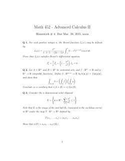
TWMS J. Pure Appl. Math., V.5, N.2, 2014, pp.152-170 A SOLUTION TO THE POLE PROBLEM FOR THE SHALLOW WATER EQUATIONS ON A SPHERE G. STARIUS1 Abstract. We consider a reduced gridding technique for the shallow water equations on a sphere, based on spherical coordinates. In a small vicinity of the poles, a longitudinal derivative is discretized at a grid-point on a parallel, by using points on the great circle through the gridpoint and tangent to the parallel. Centered one-dimensional interpolation formulas are used in this process and also in connecting adjacent segments in the reduced grid. The remaining spatial discretization is obtained by simply replacing derivatives by centered equidistant finite difference approximations. Numerical experiments for scalar advection equations and for the well-known Rossby-Haurwitz test example indicate that the methods developed work surprisingly well. Some advantages are that (i) a fairly uniform grid, with many reductions or segments, can be used, (ii) order of approximation 2p in the spatial discretizations requires only 4p + 1 points and (iii) the local and simple structure of the schemes will make efficient implementation on massively parallel computer systems possible. The paper is an attempt towards global numerical weather prediction models, by first analyzing the pole problem for reduced latitude-longitude grids. Keywords: shallow water equations, sphere, reduced grid, pole problem, segment, numerical weather prediction. AMS Subject Classification: 35L45, 65M06. 1. Introduction In this paper we present a class of methods for the numerical solution of the shallow water equations on a sphere, based on reduced latitude-longitude grids. Zonal derivatives close to the poles are discretized at each grid-point on a parallel, by using points on the great circle passing through the grid-point and being tangent to the parallel. A somewhat simplified overview of this technique is illustrated in Figures 1 and 2 below. We shall call it the Pole Tangent Derivative method, or just the PTD method. When zonal derivatives are approximated, using only points on the relevant parallel, we refer to the procedure as the Pole Parallel Derivative method, or just the PPD method. This has been the standard approximation for difference methods using latitude-longitude grids. We recall that a parallel is a circle with constant latitude. Consider the use of formulas for the PTD and the PPD methods, with 2p + 1 points on the relevant great circle and on the relevant parallel, respectively. The theoretical justification for replacing the ordinary PPD approximation by PTD, in a vicinity of the poles, is that for PTD the discretization error is O(∆θ2p ), and for PPD only O(∆θ), where ∆θ is the latitudinal step. Suppose we have n = 2` grid-points near the equator, then ` − 3 reductions, by the factor 2, are needed to obtain 23 grid-points on the parallel closest to a pole. This results in ` − 2 segments on each hemisphere. As reported in Section 4, we have successfully used 8 segments, 1 Department of Mathematics, Chalmers University of Technology and the University of G¨ oteborg, Sweden, e-mail: [email protected] Manuscript received February 2014. 152 G. STARIUS: A SOLUTION TO THE POLE PROBLEM FOR THE SHALLOW WATER ... 153 corresponding to n = 210 , in many numerical experiments. This is in sharp contrast to, cf. [2,8], where it is stated that only very few reductions can be made without significant error growth near the poles. We may conclude that the PTD method has made it possible to use many segments. To emphasize the use of many segments, we shall call the methods considered in this paper segmented methods. Our schemes should be seen as a first step towards a global numerical weather prediction (NWP) model. Static, and perhaps also dynamic, adaptivity should be implemented. This would require mesh refinements and eventually also the use of discretizations more suitable than centered approximations, for sharp weather fronts, cf. [8,9]. The question is not how much adaptivity we need, but rather how much we can afford. In this paper we restrict ourselves to the basic methods. We will only consider Eulerian formulations here, but it would be of interest to use PTD also in connection with semi-Lagrangian schemes. We point out that our methods are not conservative in a strict sense, but in our example, at the end of Section 4, Table 10, the deviations are of the order 0.01% after 10 days, which must be less than needed for weather prediction. See [6], page 2, item 1 with title: Mass conservation. The paper is organized as follows. In Section 2 we write down the shallow water equations in spherical coordinates and discuss the grid systems employed. We introduce the so called distortion factor, which is used for the segmentation of the sphere. We also present formulas for interpolation and for approximation of derivatives, typical for our schemes. Section 3, which is the central part of this paper, discusses various aspects of the pole problems and their appropriate treatments. In Section 4 several numerical experiments for advective equations and for the Rossby-Haurwitz problem are described. For the latter we also consider conservation properties for mass and energy. Finally, in our concluding Section 5, we consider possible further investigations. We will now briefly comment on some other methods considered in the literature, and their relation to the methods of this paper. Our main sources are the two review papers, Staniforth and Thuburn [6] and Williamson [11]. Both contain a great number of references, complementing the ones given here. Most operational global weather forecast models are based on full latitude-longitude grids [6] and semi-Lagrangian schemes [11]. By instead using reduced grids, like in this paper, the number of grid-points can be decreased to about two thirds, which is a considerable saving. Furthermore, the scalability problems at the poles for full latitude-longitude grids [6] are completely removed. Obviously there are other quasi-uniform grids than ours, for example the geodesic grids, among which the cubed sphere and the icosahedral grids seem to be the most popular. Cubed sphere grids consist of quadrilaterals, and icosahedral grids are generally triangular. Both avoid clustering and scalability problems at the poles. The cubed sphere grids, with angles up to 120 degrees, are briefly commented on in Section 5. The triangular icosahedral grids have some drawbacks, according to [6,11]. Reasonably simple schemes tend to be of lower order, such as second order, if applied on a plane uniform grid. In particular higher order schemes support computational modes and noise. It is becoming more and more important to design NWP methods that can use up to hundreds of thousands of processors in an efficient way. This evolution may lead to the return of explicit time integration, cf. [9]. This in turn will probably lead to the use of Eulerian formulations instead of semi-Lagrangian ones, because it seems to be very hard to construct reasonable semi-Lagrangian schemes of higher order, and the possibility to take longer time steps than for Eulerian schemes has disappeared. 154 TWMS J. PURE APPL. MATH., V.5, N.2, 2014 Considering the above and the experiments in Section 4, methods based on grid systems used in this paper, together with PTD, seem to compare favorably with other alternatives. In particular, we refer to the following properties associated with our methods: (i) Simplicity of grid structure, (ii) good scalability, (iii) quasi-uniformity, (iv) orthogonality, (v) quite sufficient conservation of mass for NWP, and (vi) simple efficient high order discretizations. Most test runs in Section 4 were made for spatial discretizations of orders 8 or 10. 2. Governing equations, grid systems and some basic discrete formulas Let us first recall the transformation between Cartesian and spherical coordinates x = a cos θ cos λ, y = a cos θ sin λ, 0 ≤ λ < 2π, − π2 ≤ θ ≤ π2 , z = a sin θ, (1) where a is the radius of the earth, λ the longitude and θ the latitude. The advective form of the shallow water equations in spherical coordinates is given by ut = −(a cos θ)−1 (uuλ + Ψλ ) − a−1 vuθ + (f + a−1 u tan θ)v, vt = −(a cos θ)−1 uvλ − a−1 (vvθ + Ψθ ) − (f + a−1 u tan θ)u, (2) Ψt = −(a cos θ)−1 (uλ Ψ + uΨλ ) − a−1 (vΨ)θ + a−1 vΨ tan θ, where Ψ is the geopotential, f = 2Ω sin θ the Coriolis parameter, Ω the rotation rate of the earth and, finally, u and v are the eastward and the northward velocity components, respectively. We notice, in particular, that tan θ and (cos θ)−1 are unbounded near the poles, which is a problem that will be attended to in Sections 3.1 and 3.2.3, respectively. The factor (cos θ)−1 will be canceled using the PTD method. In Section 3.1 we will represent the velocity vector by its orthogonal projection onto the equatorial plane, where it is expressed in Cartesian coordinates, U and V , say. In a proximity of the poles the system (2) will be expressed in terms of U and V , instead of u and v, which yields a system with bounded coefficients. Throughout this paper we assume that the solutions are smooth on the whole sphere, in local Cartesian coordinate systems. Further we assume that the same physical mesh-length is suitable everywhere. This means that it is desirable to keep the variation in the physical resolution as small as possible. Let us now look at the reduced grid systems of interest in this paper. The latitudinal step ∆θ is kept constant on the whole sphere, in contrast to the longitudinal step ∆λ, which will be increasing and piecewise constant from the equator to the poles. The distances from a grid-point to its nearest neighbors in the λ and θ directions should be as equal as possible. For this reason we define the distortion factor as d = max(∆s/∆θ, ∆θ/∆s) ≤ dmax , ∆s = ∆λ cos θ. (3) This will be used for partitioning the sphere into segments, within which ∆λ is constant. As we move from the equator to a pole we will sometimes increase ∆λ to q∆λ, where q > 1 is predetermined. Suppose ∆θ/∆s has reached the value dmax , then we ought to have the equality √ q∆s/∆θ = ∆θ/∆s = dmax and hence dmax = q, in order to minimize dmax for given q. We now consider the simplest case, namely q = 2, which is used in our numerical experiments in Section 4. Let n = 2` be the number of grid-points on a parallel at the equator, set m = 14 n G. STARIUS: A SOLUTION TO THE POLE PROBLEM FOR THE SHALLOW WATER ... 155 and define 1 1 θi = (i − )∆θ, i = 1, . . . , m, where ∆θ = π, 2 2m − 1 which implies θm = 21 π. Define the segments Sj by the sets ½ ¾ √ 1 ∆θ 2π i | 1 ≤ i < m, √ < ≤ 2 , ∆λ = `+1−j , j = 1, . . . , ` − 2. cos(θi )∆λ 2 2 The structures of the grid systems for ` = 8, 9, 10, 11 are given in Table 1. Each row in the subtables correspond to a segment Sj . The third and the fourth columns contain the number of parallels corresponding to the segment and the number of grid-points on each parallel, respectively. Table 1. Structures of grid systems with q = 2 `=8 segment n = 256 interval 1 2 3 4 5 6 1-31 32-49 50-56 57-60 61-62 63 ` = 10 segment n = 1024 interval 1 2 3 4 5 6 7 8 1-127 128-197 198-227 228-241 242-248 249-252 253-254 255 width length 31 18 7 4 2 1 256 128 64 32 16 8 width length 127 70 30 14 7 4 2 1 1024 512 256 128 64 32 16 8 `=9 segment n = 512 interval 1 2 3 4 5 6 7 ` = 11 segment 1-63 64-98 99-113 114-120 121-124 125-126 127 n = 2048 interval 1 2 3 4 5 6 7 8 9 1-255 256-394 395-454 455-483 484-497 498-504 505-508 509-510 511 width length 63 35 15 7 4 2 1 512 256 128 64 32 16 8 width length 255 139 60 29 14 7 4 2 1 2048 1024 512 256 128 64 32 16 8 From the last four rows in the subtables we see that the pattern for the four segments closest to a pole is independent of the resolution, for ` ≥ 8. When n is doubled these four segments are simply squeezed towards the pole. Further notice that the equator is between two adjacent parallels of grid-points, which makes it possible for a program, for a segmented method, to be reflection invariant with respect to the equator. This is not essential, but we think it is a pleasant property. We conclude this section by some discrete formulas typical for our methods. Since such formulas can easily be derived, e.g., by computer algebra, the list below is restricted to only one order of approximation for each formula. For all segments, except the two closest to a pole, we replace all first order derivatives by centered equidistant difference approximations. Let xj = jh, for some mesh-length h, and set fj = f (xj ), where f (x) is a smooth function. Then we have f 0 (xj ) = Dx,8 f (xj ) + 1 8 (9) (ξ1 ), 630 h f = 54 (fj+1 − fj−1 ) − 15 (fj+2 − fj−2 ) + where hDx,8 f (xj ) = 4 105 (fj+3 (4) − fj−3 ) − 1 280 (fj+4 − fj−4 ). 156 TWMS J. PURE APPL. MATH., V.5, N.2, 2014 Figure 1. The grid system for n = 26 points around the equator and with 4 segments. A zonal derivative in a grid-point marked by • will be approximated by using points on the great circle through the grid-point, which is illustrated in Figure 2. Details are given in Section 3.2.3. For later use we define Dx,2p , in analogy with the above, to be a centered equidistant difference approximation of order 2p. When discretizing in a segment close to its boundary towards a pole, see Figure 1, interpolation formulas are needed for the mid-points in the zonal direction f (xj+ 1 ) = 2 1225 2048 (fj + fj+1 ) − 245 2048 (fj−1 + fj+2 ) + 49 2048 (fj−2 + fj+3 )− (5) 5 − 2048 (fj−3 + fj+4 ) + 1 8 (8) (ξ ). 2 936.2··· h f For the two segments closest to a pole we need special formulas. In Section 3.2.3 the zonal derivatives will be replaced by centered non-equidistant difference approximations of the form f 0 (xj ) = 1 h 4 X dk (f (xj + pk h) − f (xj − pk h)) + O(h8 ), (6) k=1 where the pk ∼ k, k = 1, . . . , 4, are given. The coefficients dk are computed in a preprocessor. For the values at the poles, we use interpolation along meridians of the form f (xj ) = 65 (fj+1 + fj−1 ) − 5 − 126 (fj+4 + fj−4 ) + 10 21 (fj+2 1 252 (fj+5 + fj−2 ) + + fj−5 ) − 5 28 (fj+3 + fj−3 )− (7) 1 10 (10) (ξ3 ). 252 h f In Section 4.1. the above choice is shown to compare favorably with using the differential equations, in Cartesian coordinates, at the poles. 3. The pole problem Below we consider three different problems connected to the poles. Together they are known as the pole problem. The first two are very easy to understand and overcome. The third is more difficult, both to detect and to solve. G. STARIUS: A SOLUTION TO THE POLE PROBLEM FOR THE SHALLOW WATER ... 157 The first of them is simply that if we have the same number of grid-points on each parallel, often called a full latitude-longitude grid, the grid-points will cluster near the poles and cause stability problems in the time integration. A reduced grid solves this problem, but unfortunately gives rise to the third problem below. The second problem has to do with the velocity vector v. If v = (u, v), where u and v are the eastward and northward components of the velocity, then at the poles u and v are undefined. We therefore need another representation of the velocity vector in a vicinity of the poles. Such a representation is obtained in Section 3.1 by projecting v onto the equatorial plane. The third problem is related to the approximation of zonal derivatives close to a pole, where the number of grid-points per parallel is fairly small. The colatitude for the k:th parallel, counted from a pole, is k∆θ. For k = 1 we have 8 grid-points, for k = 2, 3 there are 16 and so on. For polynomial based difference approximations to zonal derivatives, using grid-points only on the relevant parallel, the error is shown in Section 3.2.1 to be of order only O(∆θ), for any fixed k. However, by using 2p + 1 points on a suitable great circle through the grid-point the error is O(∆θ2p ), as already mentioned in the introduction. We recall that the two methods above are referred to as the PPD and the PTD method, respectively. 3.1. A representation of the velocity vector suitable in a vicinity of the poles. For each point (λ, θ) on the sphere, except the poles, the velocity vector v can be expressed in an orthonormal basis eλ , eθ , consisting of the unit tangents to the parallel and the meridian through the point, respectively, and we have v = u eλ + v eθ . The orthogonal projection of v onto the xy-plane, corresponding to (1), is denoted by P v = −U ex + V ey , where the minus sign for U is chosen in order to get nicer formulas later on. Elementary geometric considerations give P eλ = − sin λ ex + cos λ ey and P eθ = −(cos λ ex + sin λ ey ) sin θ and since P is a linear operator we find µ ¶ U V µ =A u sin θv ¶ µ , A= ¶ sin λ cos λ cos λ − sin λ , (8) where AT = A−1 = A. Now we shall transform (2) by using (8) to express derivatives of u and v in terms of the new variables U and V . To achieve this we multiply the second equation in (2) by sin θ and then write the first two equations in vector form as µ u sin θ v 1 − a µ ¶ t 1 =− u a cos θ Ψλ / cos θ sin θ Ψθ − cos θ v 2 µ u sin θ v ¶ µ + ¶ 1 − v a λ tan θ u+f a µ ¶µ u sin θ v ¶ − θ v − sin θ u ¶ . Now by using µ u sin θ v ¶ µ =A U V ¶ µ and B = sin λ cos λ cos2 λ 2 − sin λ − sin λ cos λ ¶ , 158 TWMS J. PURE APPL. MATH., V.5, N.2, 2014 a somewhat tedious computation yields the transformed system µ ¶ µ ¶ µ ¶ µ ¶ 1 1 U U −V U − = − u − v + 2Ω V λ a V θ U V t a cos θ ¶ µ ³u ´ µ U ¶ 1 Ψλ / cos θ − A + cos θ , + 2Ω cos θ B sin θ Ψθ − cos θ v 2 V a a 1 ( uΨλ + ( sin λ Uλ + cos λ Vλ )Ψ ) − Ψt = − a cos θ 1 1 − cos λ (U Ψ/ sin θ)θ + sin λ (V Ψ/ sin θ)θ . a a (9) In this way we have gotten rid of the unbounded function tan θ, which is present in (2), and in Section 3.2.3, (cos θ)−1 will also be canceled. Mainly for reasons of implementation it would be advantageous to have a simpler system than (9). For high resolution the factor sin θ is close to 1 in a vicinity of the northern pole and to −1 near the southern. We therefore replace (8), notice not approximate, by the following mappings µ ¶ µ ¶ µ ¶ µ ¶ u U u U =A and =A , (10) v V −v V for the northern and the southern poles, respectively. In a manner similar to before we get the transformed systems for the northern and the southern pole as follows. The North Pole: µ ¶ µ ¶ µ ¶ µ ¶ 1 1 1 U U U Ψλ / cos θ = − u − v − A + V t V λ a V θ a Ψθ a cos θ µ ¶ 1 1 u −V , +(f − tan( π − θ)) U a 4 2 1 Ψt = − ( uΨλ + ( sin λ Uλ + cos λ Vλ )Ψ ) − a cos θ 1 1 1 1 − ( cos λ (U Ψ)θ − sin λ (V Ψ)θ ) − tan( π − θ)v Ψ. a a 4 2 (11) The South Pole: µ ¶ µ ¶ µ ¶ µ ¶ 1 1 1 U U U Ψλ / cos θ = − u − v − A − V t V λ a V θ a −Ψθ a cos θ µ ¶ u 1 1 −V −(f + tan( π + θ)) U a 4 2 1 Ψt = − ( uΨλ + ( sin λ Uλ + cos λ Vλ )Ψ ) + a cos θ 1 1 1 1 + ( cos λ (U Ψ)θ − sin λ (V Ψ)θ ) + tan( π + θ)v Ψ. a a 4 2 (12) We note that terms of type tan(·) have now reappeared, but in a bounded form and, in fact, vanish at the poles. From now on we assume that the velocity components U and V are smooth functions at the poles. G. STARIUS: A SOLUTION TO THE POLE PROBLEM FOR THE SHALLOW WATER ... 159 3.2. The pole problem for scalar valued functions. We will now study different types of approximations for zonal derivatives in a vicinity of a pole. Firstly, polynomial based formulas, using only points on a parallel, are considered in Section 3.2.1, called the Pole Parallel Derivative method, PPD. Then, in Section 3.2.2, we will briefly consider interpolation on parallels by using trigonometric polynomials. Finally, in Section 3.2.3, we focus on the Pole Tangent Derivative method, PTD, which is our preference. See Figure 2, which illustrates the situation on the positive x-axis, λ = 0, for the first three parallels closest to a pole. 3.2.1. The Pole Parallel Derivative method, PPD. Let F be a smooth function in a vicinity of a pole. Since the coordinate z is determined by x and y we can write F = F (x, y). For simplicity, we normalize the scale so that a = 1. Whenever the symbol a appears again in the text, it is the radius expressed in meters. We will now look at discretization errors for centered difference approximations of the same kind as (4). On the kth parallel we have Dλ,2p Fk (λ) = Dλ Fk (λ) + (−1)p+1 cp ∆λ2p Dλ2p+1 Fk (λ) + O(∆λ2p+2 ), where Fk (λ) = F (sin(k∆θ) cos λ, sin(k∆θ) sin λ) and, e.g., c3 = 1/140, c4 = 1/630 and c5 = 1/2772. We recall that Dλ = d/dλ. By repeated differentiation we get Dλ2p+1 Fk (λ)|λ=0 = (−1)p sin(k∆θ)Fy |λ=0 + O(sin2 (k∆θ)), and our wanted formula, with only the dominant error term written out, will be Dλ,2p Fk (λ)|λ=0 = Dλ Fk (λ)|λ=0 − cp ∆λ2p sin(k∆θ)Fy |λ=0 + · · · (13) We note that λ = 0 corresponds to a grid-point on a parallel. The error terms for interpolation are quite similar. The pole problem, of our third kind, can be characterized by stating that we only get a first order approximation for the zonal derivative in ∆θ, the basic discretization parameter, by using a polynomial based formula containing grid-points on the parallel. Let us 1 recall that for k = 1 we have ∆λ = 41 π, for k = 2, 3, ∆λ = 18 π and for k = 4, 5, 6, 7 ∆λ = 16 π. 1 8 −9 The accuracy can still be good, particularly away from the pole, for example c4 ( 16 π) ∼ 3.510 . Actually for simple advection problems, the PPD method seems to work fairly well, which can be seen for example in Section 4.1. When the velocity vector is present the situation is different, as it is, e.g., in the Rossby-Haurwitz problem. We shall return to this in Section 4.2. 3.2.2. Interpolation with trigonometric polynomials on parallels. Interpolation with trigonometric polynomials will be used on the first three parallels, and is an important part of the PTD method. Let us first introduce the trigonometric polynomial N X 1 SN (λ) = a0 + ( aν cos(νλ) + bν sin(νλ) ). 2 ν=1 Three different interpolation methods will be considered below, but only formulated for a parallel closest to a pole. In the simplest case only function values are used at the grid-points, in the second case first order derivatives are used as well, and finally also second order derivatives are added. The derivatives needed will be approximated by PTD, more of this later. For k = 1 we have ∆λ = 14 π, λj = j∆λ, with j = 0, . . . , 7. The following are our three interpolation methods: (i) Given the data F1 (λj ), j = 0, . . . , 7, find the trigonometric polynomial S4 (λ), with b4 = 0, such that S4 (λj ) = F1 (λj ), j = 0, . . . , 7. (ii) Given the data F1 (λj ), F10 (λj ), j = 0, . . . , 7, find the trigonometric polynomial S8 (λ), with a8 = 0, such that S8 (λj ) = F1 (λj ), S80 (λj ) = F10 (λj , j = 0, . . . , 7. 160 TWMS J. PURE APPL. MATH., V.5, N.2, 2014 (iii) Given the data F1 (λj ), F10 (λj ), F100 (λj ), j = 0, . . . , 7, find the trigonometric polynomial 0 (λ ) = F 0 (λ ), S 00 (λ ) = F 00 (λ ), S12 (λ), with b12 = 0, such that S12 (λ) = F1 (λj ), S12 j j 1 j 12 j 1 j = 0, . . . , 7. The condition numbers for the three systems √ of linear equations, for the coefficients in the trigonometric polynomials, in the 2-norm, are 2, about 10 and about 200, respectively. For k = 2, 3 we have ∆λ = 18 π, λj = j∆λ, where j = 0, . . . , 15. The condition numbers for (i) and √ (ii) are now 2 and about 20, respectively. In [4] it is proved that the interpolation error, corresponding to method (i) and 8 points, is O(∆θ4 ). The proof can easily be generalized to any even number of points for the case (i), and, with some effort, for the cases (ii) and (iii). The order of approximation is half the number of data values. Thus the interpolation errors, using 8 points, for (ii) and (iii) are O(∆θ8 ) and O(∆θ12 ), respectively. 3.2.3. The Pole Tangent Derivative method, PTD. Many variants of this method or procedure are possible. Their common feature is represented in Figures 1 and 2. The order of approximation determines the number of points that will be used on the tilted great circles. To be able to use PTD for k = 1, 2, 3 in a convenient way we will work with 32 points per parallel, as used in the third segment. The active grid-points are only those given in Table 1. The interpolation required will be performed using trigonometric polynomials as in (i), (ii) or (iii) above. Since we interpolate and differentiate numerically on meridians in a vicinity of the poles by centered formulas, it is advantageous to make extensions beyond the poles for a number of parallels using 32 points. This will be done in such a way that a column in our array corresponds to a meridian. Below we give the main features of the algorithm for PTD on three parallels, with more details thereafter. (1) At the poles we determine a value of a dependent variable by using a formula such as (7) in the four different directions λ = 0, 14 π, 12 π, 34 π, and then taking the mean value. (2) For k = 2, 3 we use trigonometric interpolation using 16 function values to determine the 32 values needed. Extensions are then made over the poles for the two parallels. (3) For k = 1 we approximate Fλ and sometimes even Fλλ by PTD, i.e., formulas such as (6), and then subtabulation by methods (ii) or (iii) to 32 points. Extensions are then made over the poles for the parallel. (4) For k = 2, 3 we approximate Fλ by PTD. (5) Either we stop here, or else we go back to item 2, where this time also Fλ is used in the interpolation. Continued iteration is also possible, but we have not seen any advantage of this, in our examples. For each parallel on which we use PTD, data have to be supplied, for the determination of the points in (6), marked by ∗ in Figure 2. This figure corresponds to the following data for the first three parallels: k=1 m p p p p p 4 2 3 4 5 6 k=2 m m m p p p 2 4 5 4 5 6 k=3 m m m m p 1 2 3 4 5 p 6. Here the letter m stands for a meridian and the letter p for a parallel. An integer under a letter m is the number of the meridian counted from, but not including, the meridian λ = 0. An integer under a letter p denotes the number of the parallel counted from the pole. For example, G. STARIUS: A SOLUTION TO THE POLE PROBLEM FOR THE SHALLOW WATER ... 161 λ=0 Figure 2. An illustration of the pole tangent derivative method, PTD, used to approximate zonal derivatives on the three parallels closest to a pole. Only grid-points on one meridian are marked by • and great circles, being tangents to parallels through these points are drawn. For each point • we have marked the points on the corresponding great circle by ∗, that are used in the difference approximation to the zonal derivative. The vertical meridian in the figure corresponds to λ = 0, which will be referred to in the text. for the third parallel and the corresponding tangent, containing points marked by ∗ in Figure 2, the first four stars lie on meridians with numbers 1, 2, 3 and 4, and the last two stars lie on parallels with numbers 5 and 6. We decide, e.g., by using a suitable figure, which points ∗ to choose and then determine the corresponding input data by the rules above. It can easily be checked that the great circle through the point (λ, θ) = (0, 21 π − k∆θ) that is also tangent to the parallel at this point is, x = a sin(k∆θ) cos τ, (14) y = a sin τ, 0 ≤ τ < 2π. z = a cos(k∆θ) cos τ, Note that y = 0 for τ = 0. We shall now express ∂λ = ∂/∂λ in term of a derivative with respect to τ , and ∂λ2 in derivatives with respect to τ and θ. For this reason we want to write the angular spherical coordinates (λ, θ) as functions of τ on the tilted great circle. On the northern hemisphere we have 1 (λ, θ) = (λ(τ ), θ(τ )), where θ(0) = π − k∆θ and λ(0) = 0. 2 Using (1) and (14) we get tan λ = tan τ / sin(k∆θ) and sin θ = cos(τ ) cos(k∆θ) and by differentiation it follows that λ0 (0) = 1/ sin(k∆θ), λ00 (0) = 0 and θ0 (0) = 0 , θ00 (0) = −1/ tan(k∆θ). On the southern hemisphere τ = 0 is replaced by τ = π and the last derivative changes to θ00 (π) = 1/ tan(k∆θ). Now a smooth function F (λ, θ) on a tilted great circle is reduced to F (λ(τ ), θ(τ )) and Dτ F = Fλ λ0 + Fθ θ0 . Setting τ = 0, π we arrive at the simple formula Fλ = sin(k∆θ)Dτ F. (15) In a similar manner, differentiating twice we obtain Fλλ = sin2 (k∆θ)Dτ2 F ± sin(k∆θ) cos(k∆θ)Fθ , (16) 162 TWMS J. PURE APPL. MATH., V.5, N.2, 2014 where the + and − signs are chosen near the northern and the the southern poles, respectively. The formula (16) will only be used for k = 1. We now consider the determination of the points ∗ in Figure 2. Therefore we write down the equations for meridians and parallels, in parameter form, denoting the parameters in both cases by σ. The meridian, with constant latitude λ, is given by x = a sin σ cos λ, (17) y = a sin σ sin λ, 0 ≤ σ < 2π, z = a cos σ, where σ = 0 corresponds to the northern pole, and the parallel with colatitude j∆θ by x = a sin(j∆θ) cos σ, y = a sin(j∆θ) sin σ, 0 ≤ σ < 2π. z = a cos(j∆θ), (18) Fortunately, the parameters σ and τ for the points of intersection can easily be determined. In fact, for the intersection between the tilted great circle (14) through (λ, θ) = (0, 21 π − k∆θ) and the meridian (17), we have ½ tan τ = sin(k∆θ) tan λ, (19) tan σ = tan(k∆θ)/ cos λ, and for the intersection between the tilted great circle (14) through (λ, θ) = (0, 21 π − k∆θ) and the parallel (18), the two parameters can be determined by ½ cos τ = cos(j∆θ)/ cos(k∆θ), j > k. (20) cos σ = tan(k∆θ)/ tan(j∆θ), When we have evaluated the τ -values, τ1 , τ2 , · · · say, on a tilted great circle, then we get p1 = τ1 /∆θ, p2 = τ2 /∆θ, · · · , which appear in (6), and the coefficients in the difference approximation can be computed. Before this approximation can be used for a dependent variable, the latter has to be interpolated at the points in the formula, which is done either on a meridian, with step 1 ∆θ, or on a parallel with 32 points, i.e., with step ∆λ = 16 π. In both cases the interpolation is centered. The PTD method is invariant under rotation of an angle, ∆λ = 41 π, 18 π, and 18 π on the first three parallels, respectively, which considerably simplifies the implementation. We conclude this section by a simple numerical example, in which we compare different alternatives to approximate zonal derivatives near a pole. Our three alternatives are PPD, PtrigD - which means symbolic differentiation of an interpolating trigonometric polynomial and PTD. Since high resolution seems reasonable in this context, we let ` = 10, corresponding to 1024 grid-points at the equator. We choose a smooth function with fairly high variation in a vicinity of the northern pole, F (x, y, z) = sin( 20(x + y + z − 1) + 200(x2 − y 2 + (z − 1)2 ), which can be expressed in terms of λ and θ by using (1). The derivative Fλ will be approximated. For PTD the order of approximation is 8 and for PPD the formula (4) is used. A relative error measure, cf. [10], for the approximative derivatives on a parallel, will be used in Tables 2 and ˜ be an approximation to a, both in Rd , and define a relative error as 3. Let a max |˜ aj − aj |/ max |aj |. j j (21) Table 2 shows that PDT is superior for k = 1 and for k = 2, 3 also considerably better than PPD. On the second and third parallels there are 16 points and the PtrigD method is quite accurate. G. STARIUS: A SOLUTION TO THE POLE PROBLEM FOR THE SHALLOW WATER ... 163 Table 2. Relative errors (21) for approximations to Fλ parallel k 1 2 3 PPD −3 4.3 · 10 2.9 · 10−4 9.4 · 10−4 PtrigD −4 6.6 · 10 4.0 · 10−7 6.7 · 10−6 PTD PPD/PTD −6 2.3 · 10 6.1 · 10−6 4.0 · 10−5 1870 48 24 In many papers the pole problem, when using PPD, has been associated with high curvature of the parallel. For this reason we look at the errors in segment 3, in Table 3. The errors are Table 3. Relative errors (21) as function of ’curvature’ Segment 3 PPD k relative error 4 2.1 · 10−5 5 5.3 · 10−5 6 1.2 · 10−4 7 2.4 · 10−4 clearly increasing in k, i.e., when the curvature is decreasing. This can easily be understood by studying the physical steps cos θ ∆λ. Curvature plays no direct part in the pole problem. The culprit is the small number of grid-points used per parallel within a segment, close to a pole, for a reduced grid. However, the problem can be overcome by using the PTD method. This method is fairly easy to implement and its influence on the total computing time negligible, in particularly for high resolution. 4. Numerical experiments In this section we shall use our methods numerically for two test cases proposed by Williamson et al. [10], namely the cosine bell advected around the sphere and the Rossby-Haurwitz problem. All computations were carried out in double precision according to the IEEE standard. Since the cosine bell has discontinuous second order derivatives we shall also use a smooth bell, based on the function − 1 sb(x) = e x(1−x) , for 0 < x < 1, and 0 elsewhere, which is infinitely differentiable. We will compare the different methods corresponding to PPD, PTD and PtrigD. For the scalar advection equations the difference between the methods is fairly insignificant, since PPD works quite well for these simple problems. This has been observed earlier, e.g., in [2]. However, the situation is different when the velocity vector is time dependent, i.e., when the equations of motion are involved. Smoothing is essential for our methods to work properly and will be achieved by adding a so called ’hyperdiffusion’ term to each equation. Let L be the difference operator corresponding to the five-point formula for the Cartesian form of −∇2 and add to the equations the terms −C(θ)L2 u, −C(θ)L2 v and −C(θ)L2 Ψ, respectively. The smoothing function is defined as C(θ) = Csm · R(θ), R(θ) = 1 + bθ , where Csm is given. 1 − cθ (22) By requiring that θ = π2 (1 + ²) is an asymptote to the graph of R(θ), we obtain c = π2 (1 + ²)−1 and b can then be determined by a given value of R( 12 π) > 1. In the experiments below we have used ² = 0.1 and whenever R( 12 π) is not given, the smoothing function C(θ) equals the constant Csm . The time integration will be performed by the classical explicit, fourth order Runge-Kutta method, which is convenient to implement. The present paper deals exclusively with spatial 164 TWMS J. PURE APPL. MATH., V.5, N.2, 2014 discretizations, and errors given here are intended to be independent of the time integration. For this reason time steps given in tables in Section 4.2 are generally much smaller than needed. 4.1. Advection of solid bodies. In [10] the advective wind is given by u = u0 (cos θ cos α + sin θ cos λ sin α), v = −u0 sin λ sin α, where the parameter α is the angle between the axis of the solid body rotation and the polar axis and u0 = 2πa/12 m/day, which is about 40 m/s. The advective equation is simply dΨ/dt = 0 or u v Ψt = − Ψλ − Ψθ . a cos θ a For α = 21 π, i.e., rotation around the poles, u = u0 sin θ cos λ, v = −u0 sin λ and u0 u0 Ψt = − tan θ cos λΨλ + sin λΨθ . a a For α = 0, i.e., rotation around the equator, u = u0 cos θ, v = 0 and u0 Ψt = − Ψλ . a The two physical rotations are obviously quite similar, which cannot be said about the two initial value problems formulated above. A comparison between the two cases, α = 12 π and α = 0, might still be possible and of interest. The latter because rotation around the equator with reasonably small support for the bell does neither involve the poles nor any pole problem. Accuracy of the same order, for the two cases, would be an excellent result. In item 1 of the algorithm in Section 3.2.3 we described how interpolation can be used to obtain the pole values. However, it is also possible to use the differential equation at the poles in Cartesian coordinates (x, y) and then discretize in the most obvious way. This together with PTD is accounted for in Tables 4 and 5 under the name Ppde. The title ’All’ means that all methods give about the same result. Angles are given in degrees. The value β0 for the opening Table 4. The Cosine Bell, ` = 8, β0 = 120/π · 360/256 Method α β PTD PPD Ppde All PTD PPD 90 90 90 0 90 90 β0 β0 β0 β0 120 120 order 108 · Csm 4 4 4 4 8 8 18 37 26 3 11 6 max |absolute error| 18 18 37 8.62 8.66 8.71 8.64 8.80 8.83 0.411 0.420 8.91 angle β of the bell is explained in the concluding Section 5. We see at once that PTD is only slightly better than PPD for the cosine bell, which we believe to be a consequence of the fact that the latter works quite well for scalar advection problems. It can also be seen that the accuracy is actually better for rotation around the poles than around the equator. Cancellation has probably occurred to some extent, but the result is still satisfactory. For the smooth bell and high resolution, β = 120, the PTD method is significantly more accurate than PPD. But this high accuracy is probably rarely needed. Fortunately, just interpolation for the pole values turned out to be better than the more complicated Ppde method, for the two bell problems. The errors in the last columns of the tables have been minimized in Csm , over suitable subsets of the real numbers, in order to make fair comparisons possible. G. STARIUS: A SOLUTION TO THE POLE PROBLEM FOR THE SHALLOW WATER ... 165 Table 5. The Smooth Bell, ` = 8, order = 8 Method α β PTD PPD Ppde All PTD PPD All 90 90 90 0 90 90 0 60 60 60 60 120 120 120 108 · Csm max |absolute error| 3 0.3 4 1.9 0.6 0.3 0.3 1.9 0.5 0.596 0.676 0.686 0.816 0.613 0.601 0.0153 0.0755 0.0139 4.2. The Rossby-Haurwitz test example. We will now turn to the Rossby-Haurwitz problem, which has been used frequently for meteorological tests since Phillips [3]. Initial condition for u, v and Ψ = gH are given in [10] and not here. We point out that u, v and H only vary moderately in a proximity of the poles. Despite this we get a sharp difference between PTD and PPD and a noticeable one between PTD and PtrigD. 4.2.1. Maximal and minimal values of the height after 10 and 14 days. In the tables below (9) has been used with only one exception, occurring in Table 7. The simpler variant (11),(12) is actually our method of choice, at least for high resolution. We have used the same smoothing function, corresponding to Csm = 12 · 10−6 and R( 21 π) = 6, except when it was necessary for stability reasons to increase the value of R( 21 π). Optimization for each case would be too costly and not very realistic, since it requires good approximations of the solutions to be known. In Table 6. Rossby-Haurwitz, PTD, n=1024, Time=10 days, dt=50 s ` order orderi 10 10 8 6 4 10 8 6 4 106 · Csm 12 R(π/2) min H 6 6 6 8 8208.447 8208.433 8208.394 8208.193 max H 10536.433 10536.420 10536.404 10536.350 Table 6 orderi means order of approximation for the interpolation between adjacent segments. Note that both min H and max H are increasing functions in the order of the method, which is a regular and robust behavior. The following approximations will be used as answers whenever needed min H ≈ 8208.5, max H ≈ 10536.5 (23) The first four lines in Table 7 correspond to Table 6, but with ` = 9 instead of ` = 10. We see Table 7. Rossby-Haurwitz, PTD, n=512, Time=10 days, dt=100 s No. ` 1 2 3 4 5 6(7) 7 9 order orderi 10 8 6 4 8 8 8 10 8 6 4 10 8 8 106 · Csm 12 R(π/2) min H 6 6 6 8 6 6 6 8208.629 8208.956 8209.388 8212.634 8208.835 8208.952 8208.919 max H 10537.290 10537.329 10537.390 10537.750 10537.312 10537.331 10537.319 166 TWMS J. PURE APPL. MATH., V.5, N.2, 2014 the same regular pattern but now min H and max H are decreasing with the order instead. In the last three lines we have tested some variants of line 2. In line 5 the order of approximation for the interpolation is 10 instead of 8. This has increased the accuracy but only slightly. In line 6(7) we have used PTD on 7 parallels by using 64 points instead of the earlier number, namely 32. Table 7 indicates that PTD on 3 parallels seems to be sufficient. We cannot give any guarantee for this for other problems, more experiments are needed. Finally, in line 7 the simplified variant (11),(12) has been used instead of (9), and by comparing with line 2 we see that line 7 is rather better than worse for the present problem, which makes our choice easy. Table 8 contains our most important experimental comparisons between three different methods Table 8. Comparison: PTD, PPD and PtrigD, Time=10 days Method ` dt PTD 8 9 10 8 9 10 8 9 10 200 s 100 s 50 s 200 s 100 s 50 s 200 s 100 s 50 s PPD PtrigD order 106 · Csm R(π/2) 8 12 6 8 12 6 8 12 6 8 14 min H max H 8202.381 8208.956 8208.433 8303.046 8223.945 8211.481 8202.421 8210.812 8208.206 10508.508 10537.329 10536.420 10525.319 10533.934 10534.641 10508.487 10537.516 10536.361 at the poles and three different resolutions, ` = 8, 9 and 10, for the Rossby-Haurwitz problem. PtrigD stands for symbolic differentiation of interpolating trigonometric polynomials. Note that the PTD and PtrigD methods are used only for the three parallels closest to a pole. Since min H is attained at the poles, we focus on the approximations to this value given in the table. Note also that PtrigD required much more smoothing than the other two, which must be considered a drawback. We see a significant difference between the PTD and the PPD methods at the poles. For the lowest resolution ` = 8 the difference is quite big. The differences are decreasing with increasing resolution, which can be seen as a consequence of the fact that even PPD methods, not surprisingly, give better accuracy for higher resolutions. It is advantageous that PTD is better than or equal to PtrigD for all resolutions, since, in general, trigonometric differentiation requires shorter time steps than ordinary difference approximations. Table 9. Rossby-Haurwitz, PTD, Time=14 days ` dt 10 50 9 100 order 106 · Csm 10 8 10 8 R(π/2) min H 12 6 12 6 8111.104 8111.223 8146.497 8146.019 max H 10539.532 10539.523 10526.041 10525.785 We now turn to Table 9. It is reported in [2] that two reductions per hemisphere can lead to serious growth of the errors, starting after about 10 days. For this reason we have integrated for 14 days, with two different resolutions, ` = 10 and ` = 9, and two orders of approximation, namely 10 and 8. The highest resolution is the most relevant for weather forecasts. The table and Figure 3 indicate that we do not have the same troubles with our methods as those reported in [2]. Let us assume that a substantial amount of accuracy has been lost when switching from G. STARIUS: A SOLUTION TO THE POLE PROBLEM FOR THE SHALLOW WATER ... 167 ` = 10 to ` = 9. This implies, for the case ` = 9, that the relative errors for min H and max H are about 0.4% and 0.1%, respectively, which seem to be quite modest. 100 80 60 40 20 0 −20 −40 −60 −80 −100 0 50 100 150 200 250 300 350 Figure 3. Contour curves for the geopotential for the Rossby-Haurwitz test example after 14 days, from 8100 to 10500 by 240. More details in the first row of Table 9. 4.2.2. Conservation properties for mass and energy. Let S be the segment on the sphere defined by θ1 ≤ θ ≤ θ2 , where, e.g., θ1 = 0 and θ2 = 12 π correspond to the northern hemisphere. Our measures for mass and energy on S are ZZ Zθ2 2 HdA = a S and Z2π cos θ ( H(λ, θ)dλ) dθ 0 θ1 Zθ2 ZZ 2 H(v · v + H)dA = a S Z2π cos θ ( H(v · v + H)dλ) dθ, 0 θ1 respectively. The integrals are computed numerically, applying the trapezoidal rule in the λ direction and by using interpolating cubic splines in the θ direction. The answers are obtained by using the values for u, v and H corresponding to ` = 10, and approximations by the lower resolution ` = 9. In Table 10 the latitudes are expressed in degrees and relmass denotes the Table 10. Rossby-Haurwitz, PTD, Time=10 days, dt=100 s ` θ1 - θ2 9 0 40 60 80 0 9 - 40 60 80 90 90 order 106 · Csm R(π/2) relmass relenergy -0.0003 0.0001 0.0010 -0.0003 -0.0001 -0.0010 -0.0020 0.0010 -0.0005 -0.0010 8 12 6 8 12 6 relative error for the mass, and analogously for the energy. If, for example, an approximation of the energy is too small, then relenergy < 0. The largest value of relmass deviates somewhat from the rest of the values in the same column. This might simply depend on the variation of H in λ and θ. Anyhow, the relative errors in Table 10 are fairly small. 168 TWMS J. PURE APPL. MATH., V.5, N.2, 2014 5. Concluding remarks Below we propose some investigations, which would constitute a reasonable continuation of this paper. It would be desirable to investigate additional test examples. We have earlier expressed concern about the fact that the solutions to the Rossby-Haurwitz test example vary fairly little in a proximity of a pole. In line 2 in Table 7 we have used PTD on 3 parallels and in line 6, on 7 parallels. A comparison between the pole values for the height shows a difference first in the 7th decimal. However, for other problems with more rapid variation at the poles, we cannot exclude that the situation is different. The use of PTD on 3 or 7 parallels makes little relative change in the overall computing time, for high resolution. A challenging problem for the segmented methods would be to study finer segmentations. A more uniform grid in the physical mesh-lengths leads to a smaller distortion factor (3). This makes it possible to increase the time step without losing accuracy. We recall that a fairly uniform grid is generally considered to be favorable for wave propagation problems. We think it is possible to reduce the computing time by a couple of percent by using a segmentation according to Table 11, which would be a satisfactory side effect. We now briefly consider the construction of more uniform grids. We believe it is important that the interpolation between adjacent segments is simple and repetitive. Suppose we want to increase the zonal mesh-length by a factor q = 32 or q = 43 , instead of by q = 2 as earlier. This means that the number of grid-points on a parallel, np say, reduces to 23 np or 34 np , respectively, but these numbers have to be integers. In the first case, three mesh-rectangles would be replaced by two and for the second four by three. When changing mesh-lengths, interpolation must now be done both towards the pole and towards the equator. For the special case n = 2` we first use the factor 43 and then 23 , which is then repeated. The quantity dmax appearing in Section 2 and √ √ used for the determination of the segments is now 1.5, instead of 2. If n contains factors 3 as well it seems quite easy to handle the situation. Many other values of n are possible without introducing a general coupling between two segments. Table 11 describes two segmentations that differ only at the poles. The one to the left requires nothing new at the poles, compared to Section 3, whereas the one to the right needs further study to be useful. We also note that the distortion factors for the grid systems are the two numbers 1.27 and 1.22, respectively. The number of interpolations is about 4 times greater than for the case q = 2. For ` = 10 and q = 2, in one of our experiments, the relative computing time for the interpolation between adjacent segments was about 0.66%. We recall that only one-dimensional interpolation is used, cf. the end of Section 2. We now briefly consider overlapping grid techniques [1,7] as a possible alternative to the PTD method. Suppose a segmented grid is used except at small vicinities of the poles, where we use overlapping orthogonal, almost uniform grids. If this is done in such a way that the polar grids only cover a small fixed number of parallels close to the poles, then both scalability problems and extensive interpolation can be avoided. A combination of overlapping and patching will probably be more efficient. We do not expect insufficient conservation of mass for NWP, cf. [7]. Experiments are needed for the ultimate design. In Ronchi et al. [5], an interesting gridding technique is introduced by combining the cubed sphere decomposition with overlapping grids. They used grids for each subregion such that only one-dimensional interpolation between adjacent curved rectangles was needed, which is a very nice property in this context. The methods do not involve the pole problem in any way. An experiment for the cosine bell with an opening angle β = 120/π, using a fourth order method G. STARIUS: A SOLUTION TO THE POLE PROBLEM FOR THE SHALLOW WATER ... 169 with 360 points on the equator, gave the maximal error 10.17. In Table 4 we used 256 points and with opening angle β0 = (360/256) · 120/π, and found the maximal error 8.62. Presently, we are restricted to n = 2` . We will make no further comparison but want to add a quotation from Ronchi et al. [5]: ’Although arguably the most natural coordinates for representing phenomena on a sphere, spherical polar coordinates present several disadvantages (collectively known as the pole problem) when used for numerical computations over the entire spherical surface.’ However, if the pole problem were solved, which already may be the case, then grids based on spherical coordinates seem to be the most natural choice. Table 11. Structures of grid systems with q=4/3, q=3/2 and n=1024. ` = 10 segment 1.27 interval 1 2 3 4 5 6 7 8 9 10 11 12 13 1-100 101-148 149-187 188-205 206-222 223-230 231-239 240-243 244-247 248-249 250-252 253-254 255-255 width length 100 48 39 18 17 8 9 4 4 2 3 2 1 1024 768 512 384 256 192 128 96 64 48 32 16 8 ` = 10 segment 1.22 interval 1 2 3 4 5 6 7 8 9 10 11 12 13 14 15 1-100 101-148 149-187 188-205 206-222 223-230 231-239 240-243 244-247 248-249 250-251 252-252 253-253 254-254 255-255 width length 100 48 39 18 17 8 9 4 4 2 2 1 1 1 1 1024 768 512 384 256 192 128 96 64 48 32 24 18 12 6 References [1] Browning, B.L., Hack, J.J., Swarztrauber, P.N., (1989), A comparison of three numerical methods for solving differential equations on the sphere, Mon. Wea. Rev., 117(5), pp.1058-1075. [2] Jablonowski, C., Oehmke, R., Stout, Q.F., (2009), Block-structured adaptive meshes and reduced grids for atmospheric general circulation models, Philos. Trans. R. Soc., A 367 1907, pp.4497-4522. [3] Phillips, N.A., (1959), Numerical integration of the primitive equations on the hemisphere, Mon. Wea. Rev., 87(9), pp.333-345. [4] Purser, R.J., (1988), Accurate numerical differencing near a polar singularity of a skipped grid, Mon. Wea. Rev., 116(5), pp.1067-1076. [5] Ronchi, C., Iacono, R., Paulucci, P.S., (1996), The ’cubed sphere’: A new method for the solution of partial differential equations in spherical geometry, J. Comput. Phys., 124(1), pp.93-114. [6] Staniforth, A., Thuburn, J., (2012), Horizontal grids for global weather and climate prediction models: a review, Q.J .Meteorol. Soc., 138, Issue 662, pp.1-26. [7] Starius, G., (1980), On composite mesh difference methods for hyperbolic differential equations, Numer. Math., 35(3), pp.241-255. [8] Tolstykh, M.A., Shashkin, V.V., (2012), Vorticity-divergence mass-conserving semi-Lagrangian shallow-water model using the reduced grid on the sphere, J. Comput. Phys., 231(11), pp.4205-4233. [9] Ullrich, P.A., Lauritzen, P.H., Jablonowski, C., (2010), A high-order fully explicit ’incremental-remap’ semiLagrangian shallow-water model, Int. J. Numer. Meth. Fluids, 2010. Published online in Wiley Interscience (www.interscience.com). DOI:10.1002/fld. 170 TWMS J. PURE APPL. MATH., V.5, N.2, 2014 [10] Williamson, D.L., Drake, J.B., Hack, J.J., Jacob, R., Swarztrauber, P.N., (1992), A standard test set for numerical approximation to the shallow water equations in spherical geometry, J. Comput. Phys., 102(1), pp.211-224. [11] Williamson, D.L., (2007), The Evolution of Dynamical Cores for Global Atmospheric Model, J. Meteorol. Soc. Jpn., Ser.II 85B, special issue, pp.241-269. G¨ oran C. Starius - recieved his Ph.D. in Computational Mathematics at Uppsala University, Sweden, in 1976. Became associate professor at Chalmers University of Technology, in 1986. Main scientific interest is numerical solution of partial differential equations. In particular: Overlapping grid methods, Path following and bifurcation, and presently Pde on a sphere.


© Copyright 2026