
Manual Coning Tool Instruction Sheet Hand Tools for High Pressure Catalog: 02-0035CE
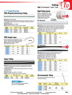
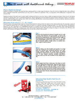
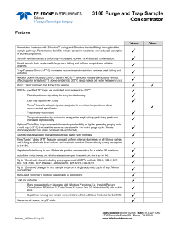
Manual Coning Tool
Instruction Sheet
Hand Tools for High Pressure
Catalog: 02-0035CE
June 2014
Operation Instructions for Manual Coning and Threading
Medium and High Pressure Tubing
Manual Kit:
1. Fig. 1 Cut tubing to length and
square off the end as close to the
required length as possible. Allow extra
length for proper engagement into
the connection as listed in Table 1. A
small amount of extra length should
be allowed to finish the end of the
tube, but excessive amounts require
additional cutting time and premature
blade wear. Note: When cutting tubing
with abrasive cut off wheel, tubing
should not be over heated effecting
material properties.
4. Fig. 2 Slide the tubing through the
collet until the end of the tube appears
in the coning tool housing window. Line
the end of the tube with the edge of the
window and tighten the collet nut firmly
in place using the collet nut wrench (see
Table 2).
Fig. 1
5. Fig. 3 Install the feed nut/cutter
support assembly into the coning tool
housing. Rotate the feed nut clockwise
until the top of the cutters just contact
the top of the tube. Do not rotate the feed nut any further at this point.
2. Install the collet and collet nut into the bottom of the coning tool housing.
Remove the cutter support feed nut from the coning tool housing and install
the cutters. This can be done by backing out the four set screws in the cutter
support. Note: When installing new blades, be sure the blades are flat against
the holder. There should be no space between the blades and the holder.
3. Fig. 2 Place the coning tool housing (or optional support arm), without
the feed nut/cutter support assembly, in a vise. The vise should be equipped
with soft jaws, and the housing should be placed in the vise to allow lubricant to flow to the cutters and cone.
Medium
Pressure
High
Pressure
TABLE 1
Tube
Size
Extra Allowance**
for Engagement
inches (mm)
Connection
Type
1/4”
SF250CX
0.55 (13.97)
3/8”
SF375CX
0.69 (17.53)
9/16”
SF562CX
0.84 (21.34)
3/4”
SF750CX
1.00 (25.4)
1”
SF1000CX
1.44 (36.6)
1-1/2"
SF1500CX
1.875" (47.63)
1/4”
F250C
0.50 (12.70)
5/16”
F312C150
1.25 (31.75)
3/8”
F375C
0.69 (17.53)
9/16”
F562C
0.84 (21.34)
9/16”
F562C40
0.81 (20.57)
1”
F1000C43
1.62 (41.1)
TABLE 2
HOUSING
COLLET NUT
CUTTER SUPPORT
SET SCREWS
POSTION
INDICATOR
CUTTER SUPPORT
FEED NUT
CUTTER
High Pressure Tubing
Medium Pressure Tubing
Tube O.D.
(inches)
Cone Length
inches (mm)
No. of
Turns
Tube O.D.
(inches)
Cone Length
inches (mm)
No. of
Turns
1/4”
5/16”
3/8”
9/16”
9/16”(C40)
0.13 (3.30)
0.19 (4.83)
0.16 (4.06)
0.28 (7.11)
0.21 (5.33)
3
3-1/2
3
5-1/2
4-1/2
1/4”
0.11 (2.79)
2
3/8”
0.13 (3.30)
3-1/2
9/16”(CX-20)
0.16 (4.06)
3
9/16”(CX-10)
0.13 (3.30)
2-1/2
Manual coning and threading tools are not available for 3/4” and 1” tubing,
see Tool Section of catalog for Coning and Threading Machine.
All dimensions for reference only and subject to change.
7. a. The distance the feed nut travels
from it's start position can be used to
gauge the amount of travel to properly
cone the tube. The amount of travel is
shown in Table 2 and is labeled “Cone
Length”.
Fig. 3
b. Another method to determine
proper cone length is to count the
number of turns of the feed nut. The
number of turns is listed in Table 2
under the heading “Number of Turns”. This includes enough advancement
of the feed nut to face off the tube. This assumes the tube is cut to length in
accordance with these instructions. The feed nut is supplied with a position
indicator (drilled hole) to help determine the number of turns.
8. Rotate the handle in a clockwise direction while simultaneously slowly
turning the feed nut in a clockwise direction. Rotate the feed nut slowly and
evenly to smoothly cone the tube. Loosen collet nut, remove tubing and
visually inspect the cone. Use deburring tool to remove any burr on inside
edge of tube after coning.
10. Apply a medium weight, high
sulphur cutting oil to threading area.
HANDLE
COLLET
Insert Tube to here
6. Fig. 3 Apply cutting oil* through the lubricant opening in the end of the
cutter holder or directly through the housing window. A medium weight high
sulphur content cutting fluid is recommended. Use the cutting oil freely during the coning operation.
Manual Threading:
9. Fig. 4 Clamp the tubing in a soft
jaw vise. Do not over tighten. Slide the
threading tool over the tube through
the guide bushing.
** See Note on page 2.
WINDOW
Fig. 2
11. Apply pressure to the top of the
threading tool to start the cutting
action. The threads are left handed, so
turn the threader counterclockwise
to thread the tube. The threading tool
may need to be periodically rotated
clockwise to break and discharge
metal chips. Apply lubricant freely
during the threading process.
Note: The lead in chamfer (larger
chamfer) on the die flutes toward
guide bushing.
*Cutting Oil P-8784
Fig. 4
Approximate Number of Turns to Thread Tubing
12. Continue to rotate die holder
counterclockwise while applying
cutting oil generously throughout
the process until threads of the
following lengths have been cut.
Male Connection
Number of Turns
SM250CX20
SM375CX20
SM562CX10/20
M250C
M250C100
M312C150
M375C100
M375C
M562C
M562C40
6.5
7.5
7.0
12
12.5
12
10
14
12
12
13. After tube is coned, threaded
and deburred, check for proper
thread fit and length with a new
collar of the proper size. Note:
Remember to flush all tubing prior
to installation with a fluid that is
compatiable with the process fluid
being used.
Male
Connection
Type
SM250CX20
SM375CX20
SM562CX20
M562C40-312
SM562CX10
SM750CX20
TABLE 3
SM750CX10
SM1000CX20
SM1000CX10
SM1500CX
M250C
M250C100
(see note)
M312C150
M375C100
(see note)
M375C
M562C
M562C40
M1000C43
Dimensions
inches (mm)
Tube Size
Outside
Inside
Diameter X Diameter
inches (mm)
1/4” x 0.109
(6.35 x 2.77)
3/8” x 0.203
(9.53 x 5.16)
9/16 x 0.312
(14.29 x 7.92)
9/16” x 0.359
(14.29 x 9.12)
3/4” x 0.438
(19.05 x 11.13)
3/4” x 0.516
(19.05 x 13.11)
1” x 0.562
(25.4 x 14.27)
1” x 0.688
(25.4 x 17.48)
1-1/2" x 0.937
(38.10 x 23.78)
1/4” x 0.083
(6.35 x 2.10)
1/4" x 0.083
(6.35 x 2.10)
5/16” x 0.062
(7.94 x 1.57)
3/8" x 0.125
(9.53 x 3.18)
3/8” x 0.125
(9.53 x 3.18)
9/16” x 0.187
(14.29 x 4.78)
9/16” x 0.250
(14.29 x 6.35)
1” x 0.438
(25.4 x 11.13)
D
0.141
(3.58)
0.25
(6.35)
0.406
(10.31)
0.438
(11.13)
0.562
(14.27)
0.578
(14.68)
0.719
(18.26)
0.812
(20.62)
1.062
(26.97)
0.125
(3.18)
0.125
(3.18)
0.125
(3.18)
0.219
(5.56)
0.219
(5.56)
0.281
(7.14)
0.312
(7.92)
0.562
(14.27)
L
(max)
Thread size*
and type
(inches)
0.344
1/4” - 28
(8.74)
0.438
3/8” - 24
(11.13)
0.500 9/16” - 18
(12.70)
0.500
9/16” - 18
(12.70)
0.625
3/4” - 16
(15.88)
0.625
3/4” - 16
(15.88)
0.781
1” - 14
(19.84)
0.781
1” - 14
(19.84)
1.000 1-1/2" - 12
(25.40)
0.562
1/4” - 28
(14.27)
0.625
1/4" - 28
(15.88)
0.687 5/16” - 24
(17.45)
0.562
3/8" - 24
(14.27)
0.75
3/8” - 24
(19.05)
0.938 9/16” - 18
(23.83)
0.938
9/16” - 18
(23.83)
0.91
1” - 14
(23.11)
*Thread is left-hand national fine (Class 2).
All dimensions for reference only and subject to change.
NOTE: M250C100 and M372C100 used in F312C150 connection at 100,000 psi (6895 bar).
Assembly and Makeup of Connection
1. Lubricate male threads of gland with a metal based thread
lubricant.* Slip gland on tubing as shown and thread collar
on tubing until one to two threads are exposed between collar
and cone.
2. A small amount of process tolerable lubricant, such as
silicone grease, on the cone tip will help with the sealing
process. Insert tubing in connection, engage gland and tighten
“fingertight”.
3. Tighten gland with torque wrench to specified torque values
in the tools section of the catalog. When tightening, the use of
an additional wrench is recommended to hold the fitting.
*Anti-Seize Lubricant: P-3580
Step 1, 2
Completed Parker Autoclave
Engineers High Pressure
Connection.
Completed Parker Autoclave
Engineers Medium Pressure
Connection.
CONING
Collet
Coning
Blades
(set of 2)
Parker
Autoclave Engineers
Medium Pressure
THREADING
Inside
Diameter
inches (mm)
1/4 (6.35)
3/8 (9.53)
†
9/16 (14.3)
9/16 (14.3)
0.109 (2.77)
0.203 (5.16)
0.312 (7.92)
0.359 (9.12)
90248
90250
90251
90251
101F-1577
101F-1601
1010-5218
101A-1897
P-0214
P-0215
P-0216
P-0216
1/4-28
3/8-24
9/16-18
9/16-18
1010-0343
1010-0344
1010-0345
1010-0345
Parker
Autoclave Engineers
High Pressure
TUBE SIZE
Outside
Diameter
inches (mm)
1/4 (6.35)
5/16 (7.92)
3/8 (9.53)
9/16 (14.3)
9/16 (14.3)
0.083 (2.11)
0.062 (1.57)
0.125 (3.18)
0.188 (4.78)
0.250 (6.35)
90248
90249
90250
90251
90251
101F-3939
101F-3939
101F-1578
1010-0883
101C-7214
P-0214
P-0205
P-0215
P-0216
P-0216
1/4-28
5/16-24
3/8-24
9/16-18
9/16-18
1010-0343
1030-0343
1010-0344
1010-0345
1010-0345
Threading Die
Order Number
Size-type*
Guide
Bushing
* All threads for Parker Autoclave Engineers medium pressure and high pressure tubing are LH national fine (class 2). †9/16 (14.3) x .312 (7.92) ID 40,000 psi (2758 bar), use MCTM920.
Note: Manual coning and threading tools for 3/4" (19.1 mm) and 1" (25.4 mm) outside diameter medium pressure tubing are not available. Model AEGCTM-2 Power Coning-and-Threading Machine is
recommended for this tubing. A minimum of 3" (76 mm) straight length is required to perform coning and threading operation with manual coning tool.
Reseating Female Cone Seats
1. Clamp fitting in soft-jawed vise.
5. Remove reamer guide nut and bushing and inspect cone seat.
2. Thread gland nut into connection and tighten to 10 ft. lbs.
6. Repeat steps 2,3,4 and 5, if necessary, until cone surface has
been restored and finish is smooth.
3. Apply cutting oil generously through opening in nut.
7. Clean fitting thoroughly to remove all chips and residue.
4. Insert reamer through guide bushing and press down firmly while
rotating clockwise approximately two full turns, relieving
pressure gradually toward end of second turn.
Connection
Type
Reamer
Complete
Guide
Nut Assembly
Reamer
Handle
SF250CX
P-0270CX
A101A-2005
P-0270
102B-7568
SF375CX
P-0271CX
A2020-7310
P-0271
102B-7568
SF562CX
P-0272CX
A2030-7310
P-0896
102B-7568
SF750CX
P-1726CX
A102A-3376
P-1726
103B-7568
SF1000CX/43F1000C
P-1727CX
A102A-3375
P-1727
103B-7568
F250C
P-0270C
A1010-0453
P-0270
102B-7568
F312C150
P-0271C150
A2040-7310
P-0271
102B-7568
F375C
P-0271C
A1020-0453
P-0271
102B-7568
F562C/C40
P-0272C
A1030-0453
P-0272
102B-7568
WARNING
FAILURE, IMPROPER SELECTION OR IMPROPER USE OF THE PRODUCTS AND/OR SYSTEMS DESCRIBED HEREIN OR RELATED ITEMS CAN CAUSE DEATH,
PERSONAL INJURY AND PROPERTY DAMAGE.
This document and other information from Parker Hannifin Corporation, its subsidiaries and authorized distributors provide product and/or system options for further
investigation by users having technical expertise. It is important that you analyze all aspects of your application and review the information concerning the product or system in
the current product catalog. Due to the variety of operating conditions and applications for these products or systems, the user, through its own analysis and testing, is solely
responsible for making the final selection of the products and systems and assuring that all performance, safety and warning requirements of the application are met. The products described herein, including without limitation, product features, specifications, designs, availability and pricing, are subject to change by Parker Hannifin Corporation and its
subsidiaries at any time without notice.
Offer of Sale
The items described in this document are available for sale by Parker Hannifin Corporation, its subsidiaries or its authorized distributors. Any sale contract entered by Parker will
be governed by the provisions stated in Parker's standard terms and conditions of sale (copy available upon request).
© 2014 Parker Hannifin Corporation | Autoclave Engineers is a registered trademark of the Parker Hannifin Corporation
Instrumentation Products Division
Autoclave Engineers Operation
8325 Hessinger Drive
Erie, PA 16509-4679
Tel: 814 860 5700
Fax: 814 860 5811
www.autoclave.com
Instrumentation Products Division
Autoclave Engineers Operation, Houston
15340 Vantage Parkway, East
Houston, TX 77032
Tel: 281 987 3828
Fax: 281 987 2318
Parker Hannifin Manufacturing Ltd.
Instrumentation Products Division, Europe
Industrial Estate Whitemill
Wexford, Republic of Ireland
Tel: 353 53 914 1566
Fax: 353 53 914 1582
02-0035CE
June2014
Parker Hannifin Manufacturing Ltd.
Instrumentation Products Division, Europe
Riverside Road, Pottington Business Park
Barnstaple, UK, EX31 1NP, UK
Tel: 44 1271 313131
Fax: 44 1271 373636
Caution! Do not mix or interchange parts or tubing with those of other manufacturers. Doing so is unsafe and will void warranty.
Caution! Parker Autoclave Engineers Valves, Fittings and Tools are not designed to work with common commercial instrument
tubing and will only work with tubing built to Parker Autoclave Engineers AES Specifications. Failure to do so will void warranty.
ISO-9001 Certified


© Copyright 2026