
HIFLYER BALLOON MAINTENANCE MANUAL LINDSTRAND TECHNOLOGIES LTD
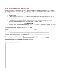
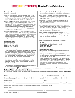
LINDSTRAND TECHNOLOGIES LTD
HIFLYER BALLOON
MAINTENANCE MANUAL
This document does not cover winch maintenance.
Please refer to separate Winch Operations & Maintenance Manual
LTL TAOM MM
Issue 2.0
i
Statement of Approval
This manual forms part of the EASA Type Certificate BA.005, first approved on 4 March
2005.
Future revisions will require approval, signified by an approval number.
Use of this Manual
This manual sets out the maintenance procedure and schedule for all LTL Captive Balloons.
As each balloon may have specific features for dedicated systems, every balloon has a
dedicated manual showing the serial number on the cover. Always make sure before
proceeding that you have the correct manual issue.
The Maintenance Manual does not always make a distinction what work can be carried out
by the operator and what can only be serviced by Factory personnel. If in doubt, always
consult the manufacturer on maintenance issues.
It is the responsibility of the balloon operator to ensure that staff engaged in inspection or
maintenance of the balloon are trained and competent to do any work they undertake.
LTL TAOM MM
Issue 2.0
ii
Record of Amendments
No.
Date
Affected Pages
Incorporated By
2.0
12.02.09
All Pages
L Barnfield
Amendments:
This manual is kept up to date by amendments consisting of loose-leaf pages, required to
add new information or amend existing information. The pages affected by an amendment
and the effective date are shown above. The pages themselves are identified by a change
of the issue number at the bottom of each page. The number after the point in the issue
number represents the amendment level of that page, eg a page marked Issue 1.4 is at
Issue 1 modified by Amendment 4. The Checklist of Pages indicates the issue level of all
pages included in this Maintenance Manual. Amendments are issued to all relevant
operators of the Lindstrand Technologies Ltd HiFlyer System on a free of charge basis
provided that the Inclusion Check Sheet is signed and returned to Lindstrand Technologies
Ltd for each issued amendment.
LTL TAOM MM
Issue 2.0
iii
Change of Ownership
If the ownership of this balloon changes, it is important for the new owners to contact
Lindstrand Technologies Ltd to ensure that they receive Maintenance Manual Amendments
and Supplements, as appropriate.
Checklist of Pages
Page No.
Issue
i
ii
iii
iv
v
vi
1
2
3
4
5
6
7
8
9
10
11
12
13
14
15
16
17
18
19
20
2.0
2.0
2.0
2.0
2.0
2.0
2.0
2.0
2.0
2.0
2.0
2.0
2.0
2.0
2.0
2.0
2.0
2.0
2.0
2.0
2.0
2.0
2.0
2.0
2.0
2.0
LTL TAOM MM
Issue 2.0
iv
Maintenance Manual Supplements
Supplement No.
LTL TAOM MM
Title
Tick if Applicable
Issue 2.0
v
CONTENTS
1.
System Description and Technical Data
1.1
Helium Gas
1.2
The Envelope
1.3
The Net
1.4
The Gondola
1.5
Load Ring and Attachments to the Gondola and Winch
1.6
The Instrument Console
1.7
Dimensions and Drawings
2.
Periodic Inspections
2.1
Technical Log
2.2
Daily Inspection/Maintenance
2.3
Monthly Inspection/Maintenance
2.4
Six Monthly Inspection/Maintenance
2.5
Annual Servicing
3.
Specific Inspections
3.1
Tensile Test of Envelope Fabric
3.2
Porosity Test of Envelope Fabric
3.3
Tensile Test of Net
3.4
Hard Landing Inspection
3.5
Suspected Envelope Penetrations
3.6
Load Cell
4.
Maintenance Log Procedures
4.1
Envelope Repair Patches
4.2
Net Repair
4.3
Repair of Structural Damage to Gondola
4.4
Helium Purity Test
4.5
Ballonet Fan
4.6
Ballonet Pressure Relief Valve
4.7
Helium Valve
4.8
Helium Fill Hose(s)
4.9
Electrical System and Wiring Diagram
Instrument Console
5.
Figures
5.1
HiFlyer Layout
5.2
Helium and Air Control Systems
5.3
Gondola Layout
5.4
Control Box - Instrument Panel
LTL TAOM MM
Issue 2.0
vi
1.
SYSTEM DESCRIPTION AND TECHNICAL DATA
1.1
Helium Gas
Helium is totally inert, clear, non-toxic and odourless. Its lift is about 1 kg/m3 (0.06
lbs/ft3) and only hydrogen has a higher lift.
The Helium molecule is very small and electrically ‘neutral’ and therefore very difficult
to contain. Even if there are no holes or pinpricks, Helium will still diffuse through
balloon fabric as a normal phenomena. For typical HiFlyer fabric, we can assume
1.5l/m2/24 hrs (0.03 gall/ft2/24 hrs). With an envelope surface area of 1600 m2
(17,222 ft3), we can expect a Helium loss of 1.5 x 1600 = 2400 litres/day (517
gall/day). This represents a loss of lift of 2.4 kg/day. To replenish from normal
Helium storage cylinders which typically hold 10 m3 or 10,000 litres (2203 gall), we
would need to empty a cylinder into the envelope every 4.2 days. This equates to
approximately 7 cylinders per month.
It is imperative that all Helium replenishment is noted in the Technical Log Sheet
LTL-TA1. The log is the most important instrument in monitoring the health of the
envelope fabric.
Air will also diffuse into the envelope and slowly dilute the Helium. This rate is
difficult to predict but it has the same trend as the helium diffusion. The Helium
purity is measured by testing a sample of Helium from the envelope with a purity
meter. Helium combines with air and the Helium purity will be the same throughout
the envelope. Thus it does not matter where on the envelope the test sample is
drawn from.
Decline in Helium purity will result in a loss of lift in direct proportion to the purity.
Helium is normally supplied in cylinders as a pressurised gas but sometimes as a
cryogenic liquid. Both are suited for filling balloons but in the case of using liquid,
make sure the necessary flow rates can be achieved. It is also important that
vaporisers (heat exchangers) of sufficient capacity are in series with the flow. If the
Helium enters the envelope too cold, it could cause fabric damage and the risk of
overfilling, as the cold gas, once inside the envelope will expand rapidly from ambient
heating.
1.2
The Envelope
The layout of the balloon is shown in Fig 5.1.
In the HiFlyer balloon, the envelope contains the gas and super pressure forces.
The net drapes over the balloon and transmits all the lifting forces to the winch and
gondola through the load ring. Both the net and the envelope are highly stressed
items; they are primary structure with no redundancy and must be inspected and
maintained meticulously. If in doubt, always consult the manufacturer.
LTL TAOM MM
Issue 2.0
1
The envelope material is a polyurethane coated fabric. The coating contains titanium
dioxide as a shield against ultra-violet radiation. The envelope is constructed from
panels joined by welding. An internal ballonet allows variations in Helium volume
without the need for venting. Some parts of the envelope are glued due to practical
restriction in welding machine access. Repair to the envelope is normally glued for
the same reasons.
The balloon envelope is a super-pressure design i.e.; the Helium cell is sealed and
an internal ballonet, which is filled with air, is allowed to expand and contract to allow
for variations in volume of the Helium cell. This way, the envelope is always full and
spherical which minimises aerodynamic drag and creates a uniform appearance.
The ballonet (and gas cell) is under slight super-pressure. The ballonet pressure is
limited by the pressure relief valve at the bottom apex and is set to 14mm (1.57”)
WG. Adjacent to the pressure relief valve is a 24V electric fan which pressurises the
ballonet.
The exterior skin of the envelope is made from uniform material, but the bladder,
which is lowly stressed, is made from a lighter material.
The envelope is fitted with two sealed Monsun valves for Helium inflation. These
valves may also be used for purging of the Helium. A top-up hose is also provided.
This runs up the side of the envelope and enters the Helium cell just above the
bladder joint.
The Helium valve which is electrically operated is located at the top apex. The
Helium and air control systems are shown diagrammatically in Fig 5.2.
Next to the Helium valve is an anemometer, a position light and an anti-collision light.
The lights are duplicated at the bottom of the gondola.
1.3
The Net
The net restrains the entire lifting force and is terminated at the top into a circular
stainless steel load ring and at the bottom into eight stainless steel wire strops. The
net material is polyester and the entire net is anti-u.v. treated after manufacture.
The metal parts of the net are manufactured from corrosion resistant steel and
require no maintenance. Assessment of accident damage to metal parts must be
carried out by Lindstrand Technologies Ltd staff.
1.4
The Gondola
The gondola is a stainless steel space frame in the shape of an octagon. It is built in
sections, which are joined by a bolt pattern for ease of transportation. The gondola
floor is made of high grade marine plywood which is screwed on to the floor box
section. The outer panels of the gondola are made from wicker in order to give the
gondola its traditional look. The inside panels are made from PVC to minimise
maintenance.
LTL TAOM MM
Issue 2.0
2
The upper half of the walkway is covered by a safety net to stop objects falling from
the gondola. There are two doors, both opening inwards for easy loading of
passengers. An instrument console is located at the operators’ station. The gondola
layout is shown in Fig 5.3.
1.5
Load Ring and attachments to Gondola and Winch
The load ring is constructed from tubular stainless steel with eight equally spaced
attachment points. It acts as a junction for all three major system components. The
net transfers all the lift generated by the balloon into the upper side of the load ring.
The gondola is suspended from the lower outer side of the ring and the main winch
cable is attached to the lower inner side of the ring via eight steel wires which
converge to a single point situated in the clear central area of the gondola.
The wires terminate onto two master links, which are looped onto a load cell shackle.
A swivel joint connects the winch cable termination to the load measuring shackle
pin, which connects to the free lift readout on the control panel.
The swivel prevents balloon rotation from twisting the winch cable.
1.6
The Instrument Console
The instrument console contains all control functions for the balloon and displays the
following parameters: helium temperature, air temperature, Helium pressure, ballonet
pressure, wind speed, battery voltage, cable tension (load cell reading/free lift).
The Helium temperature probe is located below the Helium valve and during daylight
hours it is possible for the Helium temperature to increase to 15ºC (59ºF) above
ambient.
The Helium pressure tapping is located on the Helium valve plate. The pressure
settings and limitations to which the balloon is operated are based upon the
maximum static pressure.
Ballonet pressure, tapped at the bottom of the envelope, is also displayed on a
gauge. The gauge has a manually adjustable limit, which sets the pressure at which
the fan trips in.
The wind speed anemometer is located at the top apex of the envelope in order to
measure and record wind speeds. The information is transmitted to the console and
displayed in knots or meters/ second.
Battery voltage is displayed on the voltmeter.
LTL TAOM MM
Issue 2.0
3
Winch cable tension (which translates into free lift) is measured through a load cell
located between the tether cable and the swivel. This value is important in order to
monitor Helium loss and available free lift, which can be the limiting factor when
flying in high wind.
The following warning lights are fitted to the console:
Helium valve
open
doors
open & unlocked
envelope pressure
high
The following switching functions are fitted:
Helium valve
Helium manual control
fan
panel lights
lights nav
lights strobe
security switch
-
manual/automatic
open/off/close
on/off/automatic
on/off
on/off
on/off
lock/unlock
The control panel is shown in Fig 5.4.
The instrument console is subjected to the weather and like all electrics must be kept
dry in order to work properly.
1.7
Dimensions and Drawings
The main dimensions of envelope are shown on Figure 5.1.
For detailed dimensions and information, consult Lindstrand Technologies for the
appropriate drawing.
2.
PERIODIC INSPECTIONS
Caution:
2.1
It is the responsibility of the operator to inspect and maintain the balloon as
stipulated in this manual, consulting and involving the manufacturer as
necessary.
Technical Log
All monthly and annual inspections, envelope tear off coupon test results, net cord
test results and all defects and rectification’s are to be entered in the Technical Log.
The Lindstrand Technologies Ltd warranty is only valid if the above
inspections, maintenance and Technical Log entries are completed and if the
Log is made available to Lindstrand Technologies Engineers on request.
LTL TAOM MM
Issue 2.0
4
2.2
Daily Inspection / Maintenance
The results of each daily inspection shall be recorded on the daily balloon inspection form.
Refer to Flight Manual (TAOM) Appendix 2, sheet A2-4 for the template form.
2.2.1 Structural Inspection
Structural inspection of the balloon and gondola.
2.2.1.1 Balloon (use 7 x 50 binoculars)
Envelope
No damage
No distortion
Net & rigging
-
Net centred on envelope
Not distorted
No broken strands
No frayed bridles
Not damaged and secured to envelope
-
No distortion, lugs and fasteners secure
Load ring rigging
-
Eye bolts
Load cell shackle
-
No frayed wires or damaged ferrules,
terminations and thimbles intact.
In place with nuts and split pins secured
Attachments to master links and swivel secure,
load cell lead connected and readout on control
panel.
-
check for cracks, distortion, damage
-
check condition
check welds for cracks
check for distortion, latch operation
check condition
PVC Panels
-
check condition
no cuts
no loose eyelets
lacing intact
Safety nets
-
no broken strands
lacing intact
Floorboards
-
secured
check condition
Lights
-
operational
Helium top up tube
2.2.1.2 Rigging
Load ring
2.2.1.3 Gondola
Frame & hand rails
Lugs (gondola /
cable attachments)
Doors
Wicker
LTL TAOM MM
Issue 2.0
5
•
•
•
•
•
•
•
Start winch and raise gondola approx 1.5m (5 ft).
Stop ascent
Underfloor structure
check for cracks, distortion, damage
Floorboard
check condition
Bump stops
intact
Lower gondola to platform
Switch off winch
If the inspection reveals any cracks, distortion or damage, operations should be suspended and Lindstrand
Technologies Ltd (LTL) informed of the problem. Operations shall not resume until LTL have evaluated the extent
of the problem, provided a repair solution and the problem has been resolved.
2.2.2
Winch Inspection
See: Operations Manual Ref. LTL TAOM Appendix 2 LTL-TA3
2.2.3. Control Panel Checks
Battery charger
-
Switched off and disconnect the lead from the
battery box.
2.2.3.1 Battery Pack
secured in place in the gondola
control lead connected
sufficiently charged
2.2.3.2 Helium Valve
Helium valve switch set to automatic
Manual control switch in closed position
Pressure limits correctly set (warning 38 mmWG, open 40 mm WG)
2.2.3.3 Ballonet Fan
Fan switch set to automatic
Pressure limits correctly set (on 6 mm WG, off 8 mm WG)
2.2.3.4 Circuit Breakers
All in, no malfunctions
2.2.3.5 Monitoring Instruments
Temperature indicators, wind speed and load cell read outs all
working.
2.2.3.6 Connectors
All connectors firmly in place.
2.2.4 Technical Log Record
The following data must be recorded in the Technical Log daily.
LTL TAOM MM
Issue 2.0
6
2.2.4.1 Wind Speed
Peak wind speed is used to establish the maximum passenger load.
See Operations Manual Appendix 3.
2.2.4.2 Temperature
ambient
Helium
2.2.4.3 Pressure
barometric
Helium
ballonet
2.2.4.4 Free Lift
unladen
elevated
2.2.4.5 Helium Top Up
Free lift before and after fill.
2.2.5 Function Checks
2.2.5.1
Fan auto
Fan operates
-
Envelope fully inflated
-
Ensure switch is set to automatic
Ensure flap valve closes when fan cuts
out
visual check
Fan
Monitor pressure
Pressure relief valve
-
switch to ‘manual’,
-
Fan
-
confirm opens between 12 and 15 mm
WG (or local site equivalent)
switch to auto
-
confirm illuminated visually
confirm illuminated visually
2.2.5.2
2.2.5.3 Anti Collision Lights
Strobe ‘on’
Navigation ‘on’
2.2.5.4 Doors
open - red light on
closed, latch }
and overlock }
2.3
warning light off
Monthly Inspection / Maintenance
The results of each daily inspection shall be recorded on the daily balloon inspection form.
Refer to Flight Manual (TAOM) Appendix 2, sheet A2-8 for the template form.
LTL TAOM MM
Issue 2.0
7
2.3.1 Access Envelope Crown
The top of the balloon when moored is 36.1m (118.4 ft) above the ground; the
equator is 22.28m (73 ft). To gain access to the top of the balloon, as a minimum a
cherry picker type mobile lift is required to position a man as high as possible. If
necessary a man can climb over the envelope. Ensure that his clothing has no sharp
objects (e.g. tools sticking out of pockets), no abrasive surfaces and he is wearing
soft shoes. A safety harness with two latching lines must be worn, and at least one
latching line connected to the net at all times.
2.3.2 Envelope Inspection
In addition to the items in 2.2 Daily Inspection, each calendar month carry out a
thorough inspection as follows:
2.3.2.1 Envelope washing
The envelope, net, crown ring, and banners must be thoroughly washed to
remove dirt and pollution, and prevent fungal growth, which will degrade the
fabric and ropes and shorten their life.
Cleaning Solution:
The recommended solution is:
Lindstrand Envelope Detergent No 1
Dilute with 50 ml of detergent to 5 litres water.
Do NOT use detergent neat
No other detergents, cleaning agents, or chemical additives may be used without the
written consent of Lindstrand Technologies Ltd
Other detergents may severely degrade the fabric and ropes
If in doubt use clean water only
Washing Procedure
Wash the envelope and net down from the crown, with the cleaning solution.
The solution should be ‘worked in’ around the net with a clean soft brush.
Rinse the solution off thoroughly with a gentle spray of clean water
Inspect the envelope fabric, net ropes, and electrical umbilical cord for abrasion, and
damage.
2.3.2.2 Helium Fill Tube
Inspect for condition, security of joint to envelope and of attachment to
bridle.
LTL TAOM MM
Issue 2.0
8
2.3.2.3 Crown Assembly
Clean all components
Wiring
-
Anemometer
-
Lightning Conductor
Position and Anti-Collision Lights
-
Helium Valve
-
Inspect for condition and security
of connections
Inspect for damage; security and
free rotation of head, confirm
operation
Inspect for security
inspect for damage and security,
confirm operation
inspect externally for damage
and security
leak test with fluid
2.3.2.4 Ballonet Valve and Fan
Clean valve externally, clean fan blades and duct. Inspect both components
and wiring for damage and security. During control functioning tests, confirm
satisfactory opening and closing of ballonet valve. Check valve seal for
security and condition. Confirm satisfactory opening and closing of fan duct
flap valve. See Sections 4.5 and 4.6.
2.3.2.5 Bridles
Inspect full length of each bridle from net to loadring. Specifically check the
net terminations into the 8 thimbles for security of the thimbles and condition
of the bridle splices.
2.3.2.6 Gondola
Wash and rinse off the gondola, but use only clean water on the wicker
panels if fitted. Inspect the wicker work or PVC panels for condition, and the
lacquer for cracks. Touch up with varnish on the wicker where necessary.
Raise gondola 2 metres (6.5 ft); inspect underside for tubular structure and
floorboard damage.
* Lindstrand Technologies Envelope Cleaner No 1 is recommended.
2.3.2.7 Load Cell
The balloon must be securely low moored before load cell is removed. To
remove the loadcell for replacement, maintenance or recalibration to balloon
must be secured to the winch frame by a certified load sling, rated at 5
tonnes
Note: Due to the weight of the swivel and cable, the load cell is still carrying a
load of approximately 0.02 tonne.
If readout is within zero to 0.05 tonne, reset to indicate 0.02 tonne.
Reconnect balloon to winch cable. If load cell readout exceeds 0.05 tonne,
recalibrate. See Section 3.6.
LTL TAOM MM
Issue 2.0
9
2.3.2.8 Winch System
Inspect and service as specified in the winch maintenance instructions.
2.4
Six Monthly Inspection / Maintenance – TAOM Appendix 2 LTL-TA6
The results of each daily inspection shall be recorded on the daily balloon inspection form.
Refer to Flight Manual (TAOM) Appendix 2, sheet A2-9 for the template form.
Carry out all items covered by 2.3 Monthly Inspection/Maintenance.
2.4.1 Envelope Fabric Test
CERTIFICATION MAINTENANCE REQUIREMENT
Remove two envelope test pieces, one plain and one seamed piece. Note this in the
maintenance log and send the pieces to Lindstrand Technologies Ltd. See Sections
3.1 and 3.2.
2.4.2 Net Sample Test
CERTIFICATION MAINTENANCE REQUIREMENT
Remove a test piece from the net and send same to Lindstrand Technologies. Note
the result in the Technical Log. See Section 3.3.
2.4.3
Helium Valve Operation Check
Confirm observer in position at top of balloon by radio.
Select manual control.
Lift switch to open position.
Check that red light comes on.
Immediately, move the switch to the close position. Check the red light goes out.
See Section 4.7 TAOM MM.
2.4.4 Gondola Maintenance
Clean the wickerwork (if fitted) with water and a brush using no detergent. Allow it to
dry in the open air for 24 hours. Thereafter varnish from both sides using a good
quality single pot polyurethane lacquer.
2.4.5 Battery Check
Carry out a capacity test on the gondola batteries. If result is less than 75%, renew
batteries.
LTL TAOM MM
Issue 2.0
10
2.5
Annual Servicing
An annual service is conducted on all systems after month 12.
Lindstrand Technologies Ltd for further information.
3.
SPECIFIC INSTRUCTIONS
3.1
Tensile Test of Envelope Fabric and Weld Strength
Please contact
The envelope fabric will slowly degrade in tensile and tear strength due to UV
radiation and the presence of certain airborne chemicals created by pollution. The
degree which the fabric will degrade depends on where the balloon is operated.
Consequently it is imperative to monitor fabric health by removing test panels from
the envelope and performing a tensile test. These test panels are stuck on the
envelope at the top of the balloon.
They consist of:
Base material tensile and porosity test panels.
12 off 105 x 21cm (41.3 x 8.3”) panel from each of which a tensile test piece and a
porosity test piece can be cut.
Weld tensile test panels.
12 off 105 x 21cm (41.3 x 8.3”) welded panels. The panel is welded lengthwise
along the centre line.
At the end of each 6 months in service, one complete base material test panel and
one complete welded test panel should be cut carefully off the envelope, rolled up
and sent to Lindstrand Technologies Ltd, where they are tested and the results
compared to control test pieces from the same batch of material.
The normal tensile test carried out is a 2” strip test. The test value must be noted in
the Technical Log.
If the tensile strength of the envelope fabric drops below 80 kgf/50 mm, the envelope
shall be withdrawn from service. (This is a Certification Maintenance Requirement)
3.2
Porosity test of envelope fabric
Provision is made to check a test panel for porosity each 6 months in service. This
can be done after a shorter period, but it must be borne in mind that when all 12 test
panels have been used the envelope life cannot be extended as there remains no
means of monitoring condition.
LTL TAOM MM
Issue 2.0
11
3.3
Tensile Test of Net
There are 12 x 2.44m (8 ft) lengths of BG5188 net cord tied to the equator area.
After each 6 months in service untie one cord and return it to LTL who will carry out a
tensile test and notify the customer. This tensile test must be carried out by LTL as it
requires special jaws to hold the test sample or an erroneous reading may occur.
If the tensile strength of the net braid drops below 309 Kg, the net shall be withdrawn
from service. (This is a Certification Maintenance Requirement)
3.4
Hard Landing Inspection
A hard landing is where severe wind or mechanical circumstances caused the
gondola to impact heavily on the landing platform. First inspect for obvious signs of
damage such as the rubber bump stops, landing lights, door mechanism etc.
If there are signs of mechanical damage check that the gondola is true and not
distorted, if so consult the manufacturer. Check welds for cracks, particularly
suspension eyes. See Section 4.3.
Check the electrical system for proper functioning and run through all functions on
the control panel.
3.5
Suspected Envelope Penetrations
The most common envelope penetration is bullet holes. The leak from a bullet hole
is not immediately detectable and it could take several days before the loss of helium
gets noted. If the hole is in the helium cell, it is easily patched.
If the hole has penetrated the ballonet, open the flap for access to the ballonet for
repair. Leave the flap open and the ballonet fan on to circulate fresh air.
Ensure there is a second operator outside the entry to the ballonet to monitor the
repair man.
For patching, see Section 4.1.
3.6
Load Cell
Wait for calm conditions
Ensure the balloon is securely low moored.
LTL TAOM MM
Issue 2.0
12
To remove the load cell for replacement, maintenance or re-calibration you can
a) connect the balloon directly to the winch cable.
b) secure the balloon to the winch frame by a certified load sling, rated at 5 tonnes.
Fit a 10 tonne shackle through the two master links.
Fit a 10 tonne shackle to the winch frame. Pass the sling through the shackle on the
winch frame then loop it back to the top shackle, thereby doubling the strap to
provide equivalent to 10 tonne (22000 lbs) capacity.
Remove the load cell shackle for calibration or replacement.
This sequence is reversed to reconnect the balloon to the winch cable via the load
If it is necessary to re-calibrate the load cell, this can be done by connecting a
second load cell or weigh scale of known calibration in series with the cell under test.
Then by progressively winching up to impose incremental load increases on both
load cells, their readouts can be directly compared.
Alternatively the load cell can be re-calibrated by Lindstrand Technologies Ltd.
4.
MAINTENANCE AND REPAIR PROCEDURES
4.1
Envelope Repair Patches
Patch Application
Patch – cut from envelope fabric of PU coated PVC
Cut patch with 50 mm margin around fault and radius corners
Mix and apply adhesive as per Process Specification PS036.
Apply patch with hand pressure working out from centre
Sealing cover – cut from self adhesives vinyl sheet
Allow 10mm overlap around patch
Peel off backing and apply over patch
4.2
Net Repair
The net carries the entire structural load and is therefore highly stressed and
extreme care must be exercised not to alter any dimensions while carrying out net
repairs. The net is fabricated from hollow polyester cord and the preferred repair
method is as recommended by the net manufacturer. This is a very specialised
technique and always consult LBL before any repair work. Always keep the net
clean in order to be able to observe visual deterioration.
LTL TAOM MM
Issue 2.0
13
4.3
Repair of Structural Damage to Gondola
The gondola is manufactured from hollow section stainless steel type AISA 304. The
welding method is TIG (tungsten-inert-gas) and the welding filler wire is the same as
the base material i.e. AISA 316 can also be used. The welding must be carried out
by the equivalent of CAA approved welders. Always consult the manufacturer before
undertaking any welding, as the structure may be degraded by unapproved action.
See Section 2.3.2.1
4.4
Helium Purity Test
Helium purity is directly related to gross lift. Any reduction in purity will result in a
comparative loss of lift. Due to the fact that Helium does not stratify the test sample
can be drawn from anywhere in the envelope. The Monson valve fill port is one of the
places to test purity. The test method is based on comparative testing between a
known purity of Helium (such as from a fresh helium storage bottle) and from the
sample drawn from the envelope. Most Helium testers work on the same principle
but always check the manufacturer’s instructions. Helium purity is a good sign of
envelope condition and always note the result in the Technical Log.
4.5
Ballonet Fan
The ballonet fan is a 24VDC unit operated either automatically or manually from the
instrument console. The fan is in almost constant use and sucks unfiltered air and is
therefore subjected to blockage and wear and tear from foreign object damage
(FOD). The fan is a straight DC motor with carbon brushes and these need
replacement on condition but typically every 12 months. Replacement of the fan unit
is straightforward and involves low mooring the balloon and then removing the bolt
pattern and electrical socket.
4.6
Ballonet Pressure Relief Valve
The ballonet pressure relief valve is purely electrical/ mechanical and is preset to
open at 14mm (1.57”) WG. The cracking (opening) pressure can be adjusted should
it drift out of tolerance. There is a spring tension adjustment screw at the inside peak
of the valve tower and clockwise operation will increase cracking pressure and vice
versa. Do not increase pressure above 14mm (0.55”) WG.
4.7
Helium Valve
The Helium valve is located at the very top apex of the envelope and due to its
remote location it is electrically operated and controlled manually or automatically
from the instrument console. The valve has a 24 VDC linear actuator of heavy duty
design. If malfunction occurs first check the wiring and switch gear rather than the
actuator as the most likely source of trouble. If the actuator is at fault, fit a
replacement unit.
4.8
Helium Top Up Hose
LTL TAOM MM
Issue 2.0
14
The Helium top up hose is used to top up Helium loss as this has a one-way valve
fitted inside the envelope. The integrity of the fill hose is very important as any
damage results in helium loss. If damaged, it should be replaced.
LTL TAOM MM
Issue 2.0
15
4.9
Electrical System and Wiring Diagram
The electrical system is a typical 24 VDC negative earth system using rechargeable
batteries. The batteries are charged externally and if the battery pack runs down
during operations change the whole pack as there are no means of charging the
battery pack during flight operations. Fault finding in the electrical system can be
carried out by a qualified electrician in possession of the complete wiring diagram
and this manual.
4.10
Instrument Console
The electrical components used inside the instrument console are straightforward
and require no maintenance except keeping it dry and if water has entered the
console dry everything and leave a few sachets of silica gel at the bottom of the
instrument box. Should any component require replacing, these can be supplied
from Lindstrand Technologies Ltd.
LTL TAOM MM
Issue 2.0
16
Figure 5.1 – HiFlyer Layout
LTL TAOM MM
Issue 2.0
17
HELIUM VALVE
HELIUM PRESSURE
TAPPING
ENVELOPE
GAS CELL
D I AP H R AGM
BALLONET
HELIUM FILL
HOSE
PRESSURE
CONTROL VALVE
BALLONET FAN
FLAP VALVE
(NON RETURN)
BALLOON CONTROL SYSTEMS
Fig. 5.2 – Balloon Control Systems
LTL TAOM MM
Issue 2.0
18
Figure 5.3 – Gondola Layout
LTL TAOM MM
Issue 2.0
19
Figure 5.4 – Control Box – Instrument Panel
LTL TAOM MM
Issue 2.0
20
SECURITY
LOCK
DOWN
STOP
UP
UNLOCK
WINCH CONTROL
25
FAN
PWR.
2
5
He VALVE
WINCH CTL.
(mmWG)
BALLONET PRESSURE
(mmWG)
HELIUM PRESSURE
FAN
DISP.
3
EM.
PWR.
STROBE
5
NAV.
3
CIRCUIT BREAKERS
2
PEAK
LIGHTS
DOORS
1
2
WIND
SPEED
LOAD CELL
WIND SPEED
TEMP
2
RESET
FREE
LIFT
18
+
VDO
-
24
28
CAL 3200
AMB. TEMP °C
CAL 3200
He TEMP °C
20
VOLTS
32
EM. PWR
FAN
DOORS
WARNING
OFF
ON
CHECK
AUTO
OFF
ON
PANEL
LIGHTS
PUSH
TO TEST
OFF
ON
NAV
HELIUM VALVE
AUTO
MAN
He PRESSURE
WARNING
OFF
ON
STROBE
CLOSE
OFF
OPEN
VALVE OPEN
OFF
ON


© Copyright 2026