
Manual Control ÁPRO.ENvÈ Professional
Manual
Control
Professional
ÁPRO.ENvÈ
PRO.EN
Certain computer programs contained in this product [or device] were developed by HygroMatik
GmbH ("the Work(s)").
Copyright © HygroMatik GmbH [18.02.2014]
Controls Professional
All Rights reserved.
HygroMatik GmbH grants the legal user of this product [or device] the right to use the Work(s)
solely within the scope of the legitimate operation of the product [or device]. No other right is
granted under this licence. In particular and without prejudice to the generality of the foregoing,
the Work(s) may not be used, sold, licensed, transferred, copied or reproduced in whole or in part
or in any manner or form other than as expressly granted here without the prior written consent of
HygroMatik GmbH.
Information in this manual is subject to change or alteration without prior notice.
Warning, Hazardous Voltage: All work to be performed by trained personnel only.
All electrical installation and servicing of the electrical components of this unit to be
performed by qualified electricians only. Disconnect power supply before installation
and servicing!
Page 2
1. Introduction ....................................................................................................................... 4
1.1 Typographic Distinctions ................................................................................................... 4
1.2 Documentation .................................................................................................................. 4
1.3 Directions for Use .............................................................................................................. 5
2. Safety Notes ....................................................................................................................... 6
2.1 Overview ........................................................................................................................... 6
2.2 Guidelines for Safe Operation ........................................................................................... 6
2.3 Disposal after Dismantling ................................................................................................. 7
3. Control Description and Parameters ............................................................................... 8
3.1 General description ........................................................................................................... 8
3.2 Menu ................................................................................................................................. 10
3.2.1 Menu Structure Code 10 ................................................................................................ 11
3.2.2 Reading level: ................................................................................................................. 12
3.2.3 Password (Code) entry ................................................................................................... 12
3.2.4 Parameter setting ........................................................................................................... 12
3.2.5 Setting the time .............................................................................................................. 13
3.2.6 Call up parameters ......................................................................................................... 13
3.2.7 Programming level: ........................................................................................................ 14
3.3 Operation ........................................................................................................................... 16
3.4 Function of the safety chain .............................................................................................. 16
3.5 Collective Fault .................................................................................................................. 16
3.6 Overview of error messages ............................................................................................. 17
4. Wiring diagrams ................................................................................................................ 21
5. Technical Specifications .................................................................................................. 23
Page 3
1.
Introduction
Dear Customer,
Thank you for choosing a HygroMatik steam humidifier.
HygroMatik steam humidifiers represent the latest in humidification technology.
They will impress you with their safety, ease of use and economical operation.
In order to operate your HygroMatik steam humidifier safely, properly and efficiently, please read these operating instructions.
Employ your steam humidifier only in sound condition and as
directed. Consider potential hazards and safety issues and follow all the recommendations in these instructions.
If you have additional questions, please contact us:
Tel.:
+49-(0)4193 / 895-0
(Main Number)
Tel.:
+49-(0)4193 / 895-293
(Technical Support Hotline)
Fax:
+49-(0)4193 / 895-33
e-mail: [email protected]
For all technical questions or spare parts orders, please be prepared to provide unit type and serial number (see name plate on
the unit).
1.1
Typographic Distinctions
•
preceded by a bullet: general specifications.
»
preceded by an arrow: Procedures for servicing or
maintenance which should or must be performed in the
indicated order.
Installation step which must be checked off.
italics
Terms used with graphics or drawings.
1.2
Documentation
Retention
Please retain these operating instructions in a secure, always
accessible location. If the product is resold, turn the documentation over to the new operator. If the documentation is lost, please
contact HygroMatik.
Versions in Other Languages
These operating instructions are available in several languages.
If interested, please contact HygroMatik or your HygroMatik dealer.
Page 4
1.3
Directions for Use
The proven principle of heating water by the use of electric
immersion heaters is exploited to generate steam. Using different tap water qualities or partial softened water (all humidifier
types) or fully demineralized water / condensate water (only for
humidifier type HeaterLine, HeaterCompact/Kit and HeaterSlim).
Warning: HygroMatik steam humidifiers emit steam with a temperature of 100° C. The steam may not be inhaled directly.
Proper usage also entails following HygroMatik's instructions for
installation, dismantling, reassembly, initial operation and operation and maintenance, as well as disposal procedures.
Only qualified and authorised personnel may operate the unit.
Persons transporting or working on the unit , must have read
and understood the corresponding parts of the Operation and
Maintenance Instruction and especially the chapter 2. „Safety
Notes“. Additionally, operating personnel must be informed of
any possible dangers. You should place a copy of the Operation
and Maintenance Instruction at the unit‘s operational location (or
near the unit).
The steam humidifier is not qualified for exterior application.
Page 5
2.
2.1
Safety Notes
Overview
These safety notes are required by law. They promote workplace safety and accident prevention.
Warnings and Safety Symbols
The safety symbols below identify sections containing warnings
about hazards or potential dangers. Please familiarize yourself
with these symbols.
Warning: Failure to observe this warning may result in serious
injury or death and/or damage to the unit.
Danger, Hazardous Voltage: Hazardous electrical current! Failure to observe this warning may result in injury or even serious
injury or death.
Warning: Failure to follow these instructions may result in
damage to the unit due to electrostatic discharge. The electronic
components of the humidifier control are very sensitive to electrostatic discharges. In order to safeguard these components
during installation and servicing, steps must be taken to protect
against ESD.
Reminder: Materials and consumables must be handled and/or
disposed of as required by law.
Note: Appears before explanations or cross-references which
refer to other sections of the operating instructions.
2.2
Guidelines for Safe Operation
Overview
Obey all safety notes and warnings present on the unit. In case
of a malfunction, switch off the unit immediately and prevent a
restart. Repair malfunctions promptly. After any repair work,
have qualified personnel check the safe operation of the unit.
Use original spare parts only. Additional national safety regulations also fully apply to the operation of this unit.
This unit is not designed for the use by persons (also children)
with limited physical, sensory and mental abilities - or without
knowledge and experience. Unless they are supervised or trained by a person, who is responsible for their safety.
Supervise children in order to ensure that they will not play with
the unit.
The unit is only allowed to work with connected steam hose that
safely leads the steam.
Page 6
Accident Prevention Regulations
Attention: In the event of leaky or faulty components uncontrolled hot steam may flow.
HygroMatik steam humidifiers are IP20-protected. Make sure
that the unit is protected from drips in its installed location.
Installing a humidifier in a room without water discharge requires
safety devices to protect against water leakages.
Accident Prevention Regulations
Comply with the Accident Prevention Regulation Electrical
Systems and Equipment to prevent injury to yourself and others.
Operation of the Unit:
Do not perform any work which compromises the safety of the
unit. Regularly check that all safety and monitoring devices are
functioning normally. Do not remove or disable safety devices.
Installation, Dismantling, Maintenance and Repair of the
Unit:
Disconnect unit components from power supply prior to maintenance or repair work.
Attaching or installing additional components is permitted only
with the written consent of the manufacturer.
Electrical
Work on the electrical system must be performed by qualified
personnel.
Disconnect unit components from power supply prior to work.
It is not allowed to connect the unit to DC voltage supply.
In case of a malfunction in the electrical power supply, switch off
the unit immediately. Use only original fuses with the appropriate
amperage rating. Regularly check the unit's electrical equipment. Promptly repair any damage, such as loose connections,
burned wiring or defective electrical insulation. After proper electrical installation or repair, test all safety mechanisms (such as
grounding resistance).
2.3
Disposal after Dismantling
Note: The operator is responsible for the disposal of unit components as required by law.
Page 7
3.
3.1
Control Description and Parameters
General description
The control of the HygroMatik humidifier controls the entire
humidifying process. The user interface for operation and control
of device functions is on the front of the PLC control
Description of button functions:
(F1): - increase value
- to next designator
(F3): - reduce value
- to previous designator
(F2): - quit without saving the setting
- back to previous level
(F4): - confirm value/ quit and save setting
- to next level (call menu,
submenu, parameter, value)
- call reading level
Page 8
Description of display and LED functions:
The display comprises 14 icons in 3 categories:
1. Operating modes
2. Values and measuring units
3. Switching states
Icon
Description
Colour
Error
red
(error codes F1...F8 are displayed;
detailed description see below)
Operation (humidifying) green
No requirement
green
(the safety chain is closed,
but the requirement
is below the turn-on threshold)
Relative humidity [%]
red
Incorrect control signal red
(control signal is incorrect or missing humidification is interrupted)
Page 9
Description of the switching states:
State
Description
1
Maintenance/malfunction orange
2
Operation (main contactor K1 on)orange
3
Solenoid valve Y1 activeorange
4
Solenoid valve Y2 activeorange
5
Solenoid valve Y3 activeorange
6
Solenoid valve Y4 activeorange
7
Blow-down pump
3.2
LED Colour
activeorange
Menu
Starting the system
After switching on the Hygromatik HeaterLine HL with the main
switch, a self-test is started and the water level in the cylinder
filled to operating level with a closed safety chain.
The system is then in the main menu, i.e. the current steam
output is displayed.
From here, you can get to the reading level and read out
current reading parameters (L1...L15) or get to the
programming level where parameters can be set or changed.
There is a detailed illustration of the programming steps in the
following subchapter “Menu set-up and parameterisation”.
Page 10
3.2.1 Menu Structure Code 10
Start
0.0
Main Menu
Reading Level
L_P = Reading Parameter
L0 Total steam [kg*103]
L01 Actual steam volume [kg/h]
L03 Actual value of the control input
L04 Setpoint control signal
L05 Set value [%
]
L06 Set value of target humidity (only with PI control) [%]
L07 Actual value of current humidity (only PI control) [%]
L13 Total operating hours [h]
L14 Remaining operating time until next service message [h]
L15 Remaining operating time until next standby flushing [h]
Shaded parameters
can only be accessed
by entering code (10)
Parameter Level
FF=Failure History
SF1
tF1
dF1
SF2
tF2
dF2
SF3
tF3
dF3
SF4
tF4
dF4
SF5
tF5
dF5
SF6
tF6
dF6
SF7
tF7
dF7
SF8
tF8
dF8
Code input
10
U6 Controls
E03 Control Signal
U8 Threshold control signal at 1% output
C11 Proportional part, with PI control [%]
C12 Integral part, with PI control [%]
L05 Set value [%]
L06 Set value of target humidity (only PI) [%]
H11 Counter partial blow down [kg]
H01 Duration partial blow down [s]
H17 Counter full blow down [kg]
H18 Duration full blow down [s]
A04 Standby blow down [min]
A17 Standby heating
E6 Switching signal for relay D04
E7 Switching signal for relay D06
r_S Reset maintenance interval
Up Update time/ date
CM Time, minutes
CH Time, hours
Cd Date, day
CMO Date, month
Cy Date, year
- Increase value
- Next identifier
- Decrease value
- Previous identifier
- Exit without parameter modifying
- Back to the previous level
- Confirm value/ exit with parameter modifying
- Next level (entering main menu, parameter value)
- Entering menu „reading parameter“
Page 11
3.2.2 Reading level:
In the reading level, the following reading parameters can be
called:
L0
Total Steam volume meter [kgx103]
L01
Actual steam volume [kg/h]
L03
Actual value of the control input
L04
Set point control signal
L05
Set value [%]
L06
Set value of target humidity [%] (valid only with
PI control)
L07
Actual value of current humidity [%] (valid only with
PI control)
L13
Total operating hours [h]
L14
Remaining operating time until next service
message [h]
L15
Remaining operating time until next standby
flushing [h]
3.2.3 Password (Code) entry
»
»
»
»
»
»
Press button F2 and F4 simultaneously.
The display shows „Par“.
Press button F1 until the display shows „PASS“.
Press button F4.
Set the desired value by using button F1 or F3.
To confirm the modified value press button F4 and go
automatically back one level.
The password is entered.
3.2.4 Parameter setting
A parameter should be edited:
»
Press button F2 and F4 simultaneously.
The display shows „Par“.
»
Press button F4 twice.
The display shows the first parameter.
»
»
»
»
Select the requested parameter by using buttons F1
and F3.
Call up the parameter by pressing button F4.
Set the desired value by using button F1 or F3.
To confirm the modified value press button F4 and go
automatically back one level.
Page 12
or
Press button F2 and go automatically back one level without
saving the changes.
»
3.2.5 Setting the time
»
Press button F2 and F4 simultaneously.
The display shows „Par“.
»
Press button F4 twice.
The display shows the first parameter.
»
»
»
Press button F4, enter the value 2 and press button F4.
Select the parameters for the time setting by using buttons F1 and F3 and enter the actual values.
To confirm the modifications select parameter UP and
enter value 1. After successfully safing the display
shows „0“
Note: After 48 hours without power supply all time settings disappear.
3.2.6 Call up parameters
»
Press button F2 and F4 simultaneously.
The display shows „Par“.
»
Press button F4 twice.
The display shows „UP“.
»
»
»
Select the requested parameter by using buttons F1
and F3.
Call up the parameter by pressing button F4.
Back by pushing button F2.
Page 13
3.2.7 Programming level:
Within the programming level, the following parameters can be
changed:
Parameter Designation
U6
E03
U8
C11
C12
L05
L06
H11
H01
H17
H18
A04
A17
r_S
E06
E07
UP
CΠ
CH
Cd
CΠΟ
Cy
Selection option
Control type
0 = external controller
1 = single-stage / on-off
Control signal
4 = 0-10V DC
3 = 4-20mA DC
Threshold control signal1.0-50.0
at 1% output
P fraction,
5-20%
with PI humidity control
I fraction,
5-50%
with PI humidity control
Steam generation output
limitation
25-100%
Target value rel. humidity10-100%
Meter
0-999kg (0=Off)
Partial blow-down
Flushing time
2-30sec
Partial blow-down
Meter
0-9999kg (0=Off)
Full blow-down
Flushing time
2-100sec
Full blow-down
Standby blow-down 0-1440min (0=Off)
factory setting: 1440min
Standby heating
ON/OFF
factory setting: OFF
Reset service messageON/OFF
programmed switching
see table: programmsignal, relay D04
able switching signals
programmed switching
see table: programmsignal, relay D06
able switching signals
Update Time
Minute
Hour
Day
Month
Year
Page 14
Table: Programmable switching signals for E06 und E07
Value
Description
0
Off (Function is switched off)
1
Error
2
Safety chain closed
3
Stand by
4
No demand
5
Humidification active
6
Blow down active
7
Main contactor active
8
Filling active
9
No error
10
Dry level (level sensor)
11
Operating level (level sensor)
12
Max-level (level sensor)
Level FF = Error history (only reading parameters)
Parameter
Description
SF1...F8*
Designation of error
message
tF1...F8
Time of error message
dF1...F8
Date of error message
rESE
Reset error history
(*: see also chapter „Overview of error messages“)
Page 15
3.3
Operation
If the HygroMatik Heater Line HL is released (i.e. the safety chain
is closed) and a control signal above the turn-on threshold is
applied, then the water is evaporated.
LED 2 for the state "Operation" lights up.
The current steam output in kg/h is simultaneously shown on the
display.
The top display line additionally shows operation with
.
3.4
Function of the safety chain
In the main display window, you can see whether the system is
released for operation. Release (=closing of the safety chain
between terminals X1.1 and X1.2) requires a customer-provided
potential-free make contact. Several safety contacts (opener/NC)
can be serially connected here.
No requirement:
If programmable logic controller shows
then the safety
chain is closed but the requirement is below the turn-on
threshold. There is no need for humidification.
Ready for use:
If
is not shown and the display shows 0.0 kg/h, then the
safety chain is open (terminals X1.1 and X1.2 are not bypassed).
The HygroMatik Heater Line HL is operational.
3.5
Collective Fault
If an error in the HygroMatik Heater Line HL is detected by the
control, then the allocated changeover relay is deenergized
(terminals X1.28-30 NC).
At the same time, the display shows a specific error message
(F1 ... F8) and the icon
lights up in red. The HygroMatik
Heater Line HL is switched off.
If there is no error, then the changeover relay is energized.
Please refer to the following table for a detailed description of
the error and ways to remove them.
Page 16
3.6
Error
Overview of error messages
Fault report
Description
Possible cause
Rectification
Blow-down
error
Blow-down pump is not
actuated electrically.
Cable connections are
not OK.
Check cable
connections,
replace if
necessary.
Relay on the main
board not energized.
Measure voltage
on the board
terminal against N,
replace board if
necessary.
Blow-down pump
defective.
Replace blowdown pump.
Water level in the
cylinder is dropping
very slowly even
though the blow-down
pump blows down
water.
Solenoid valve does
not close properly.
Check solenoid
valve.
Blow-down pump is
working but no water is
pumped out.
Cylinder drain
clogged.
Completely clean
steam cylinder and
support to
preclude renewed
short-term
clogging.
No.
F1
Blow-down pump
blocked by hardeners.
Check blow-down
pump, drain
system and
cylinder for
hardeners and
clean.
Page 17
Error
Fault report
Description
Possible cause
Rectification
Thermo
sensor error
Thermo sensor has
tripped.
Too much lime in the
heater.
Disconnect power
supply. Wait until
cylinder has
cooled down.
Remove black
cover cap. Push
back the blue
release pin with
bent needle nose
pliers or a screw
driver.
Flue openings
blocked.
Remove lime from
the heater.
No.
F2
Remove blockage
F3
Error Max_
Niveau
Water level very
frequently at max.
level.
Solenoid valve does
not close properly.The
water level in the
cylinder is rising
slowly even though
the solenoid valve is
not actuated.
Check solenoid
valve.
Water is fed despite
switched off steam
humidifier. The inlet
solenoid valve stays
open.
Clean solenoid
valve.
The inlet solenoid
valve receives a
constant electrical
signal. (Water supply
is stopped when the
device is switched off).
One or more
relays for the
solenoid valves
hook. Measure on
the terminals,
replace board if
necessary.
Page 18
Error
Fault report
Description
Possible cause
Rectification
Filling error
Cylinder is not filled.
Solenoid valve or
supply line dirty or
defective.
Clean or replace
solenoid valve or
supply line.
Solenoid valve is not
actuated electrically.
Coil defective.
Measure and
replace coil.
Water supply not
opened.
Open water
supply.
Cable connections are
not OK.
Check cable
connections,
replace if
necessary.
Relays on the main
board are not
energized.
Check voltage an
output terminals.
The steam hose was
not laid with sufficient
slope/incline so that a
water bag has formed.
The steam flow is
obstructed. The steam
builds up pressure in
the cylinder and
presses the water into
the drain via drain
hose.
Check laying of
steam hose.
Remove water
bag.
The value of a
connected humidity
sensor (option) is
outside the normal
range.
Humidity sensor
defective.
Replace humidity
sensor.
Line break.
Replace line.
Illogical water levels
are recorded.
Float switch is
defective.
Remove and
check float switch.
The cable connection
for the float switch is
not OK.
Check cable
connection,
replace if
necessary.
The plug for the float
switch is not
connected with the
control.
Insert plug in the
control.
No.
F4
F5
F7
Error RH
sensor
Level
sensor error
Page 19
Error
Fault report
Description
Possible cause
Rectification
Vaporization
error
No water evaporated
despite requirement.
Heater defective.
Measure
resistance of
heater, replace
heater if
necessary.
Resistance
Heater
4.5kW:
approx. 36 ohm
and heater
6.75kW: 24 ohm
Failure of a phase.
(External fuse has
tripped or is
defective).
Replace external
fuse and look for
the cause.
No.
F8
Page 20
K11
11
K1214
14
11
4 5
Supply
1
8
AO1
M1
Supply 12V
11
M
7
DO6
AO2
GND
Gepr.
Norm
c
Zust.
6
DO1
DI6
GND
Lue
Name
230V
24V
DI5
8
DO2
DO3
K1
8 (14)
7 (13)
27
25
4
DO3
AI3
10
1
DO4
DI1
20
5
K12
K11
2
DI2
Y4
6
4
LAN
Y3
3
2
G
AO
3
4
SE655
controller
SMP5500/C
5
1
DO4
5 4
(+) (-)
Urspr.
Ers.f
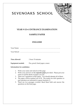
für HL 12 - 45: Leistungsteil S-042901-6
HL06-45-P 380-415V/3/50Hz
(Benennung)
K1
3
DI3
Y1 Y2
5
DO2
DI4
AI4
7
LAN
Extension module
10
DO1
28
20
DO6
30
Supply
1
31
1
Ers.d
S-072914-1
(Zeichnung Nr.)
X1 2
Sicherheitskette
Betriebsmeldung Eingang
potentialfrei / Regler/Fühler
Input
interlock system
potential free
oparation message sensor
Supply
11
06.01.14
+
T2
33
Bearb.
Datum
-
-
34
Datum
Änderung
3
0,5A
F2
33
b
2
+
solid state relay
Halbleiterrelais
blau/blue - G3
rot/red - G2
schwarz/black
weiß/white - G1
G1 Trockengang
G2 Füllen aus
G3 max. Niveau
Schwimmerstellung
a
1
G1
G2
G3
E6
E7
Störung
potentialfrei / potentialfrei / potentialfrei /
potential free potential free potential free
E6
fault message
E7
F1
Thermowächter
S1b
S1a
HYGROMATIK
Lise-Meitner-Str. 3
D-24558 Henstedt-Ulzburg
Germany
solid state relay(2 in HL 30-45)
thermo switch for each
Halbleiterrelais (2 in HL 30-45)
1,6A
for HL 6-45
control stage
für HL6-45
Steuerungsteil
1
2
1
4
in HL9
5
L3
PE
KW Heizkörper
6
5
L3
PE
von 2
Blatt 1
Phone
+49-(0)4193 / 895 - 0
6,75 KW Heizkörper
4,5
L2
4
3
L2
S-072914.000
in HL6
(Datei)
2
1
L1
C1
R1
R1
K1
N
R1
Telefax
+49-(0)4193 / 895 - 33
2
X1
L1
located at middle plate
solid state relay
Geräte-Mittelwand
Halbleiterrelais an der
only for HL6-9
power stage
nur für HL6-9
Leistungsteil
3
Bl.
4.
Wiring diagrams
Page 21
Änderung
STB 2
R1 - R5
HL27
Datum
12.11.12
08.05.08
14.07.05
b
c
a
Zust.
HL 12 / HL 18
HL 27 / HL18
X1
N
N
L1
L2
L3
L3
X1
PE
N
N
L1
L2
L3
L3
PE
Betriebsmeldung
Betriebsmeldung
Lue
Dg
Lue
Name
operation
1
3
5
7
K1
4
2
1
3
5
2
4
6
operation
7
K1
K1
6
K1
8
Datum
Bearb.
Norm
Gepr.
Halbleiterrelais an der
solid state relay
Geräte-Mittelwand
located at middle plate
8
Halbleiterrelais an der
solid state relay
Geräte-Mittelwand
located at middle plate
Lue
03.11.04
(Benennung)
Ers.f
Leistungsteil HL12-45
400V/3/N 50-60Hz
Urspr.
L1
1
2
L2
4
L3
5
1
6
L2
L1
PE
4
2
PE
L3
6
5
3
1
1
2
2
R1
R1
(Zeichnung Nr.)
S-042901-6
Ers.d
R1 - R2
in HL12
R1 - R2
in HL18
R3
R2
R2
KW Heizkörper / heating element
R1 - R3
in HL27
6,75 KW Heizkörper / heating element
6,75 KW Heizkörper / heating element
4,5
R1 - R3
in HL18
4,5 KW Heizkörper / heating element
HL 24 / HL 36
HL 30 / HL 45
HYGROMATIK
Lise-Meitner-Str. 3
D-24558 Henstedt-Ulzburg
Germany
X1
X1
N
N
L1
L2
L3
L3
N
PE
N
L1
L2
L3
1
3
5
2
4
6
L3
PE
Betriebsmeldung
Betriebsmeldung
operation
1
3
5
7
K1
2
4
operation
7
K1
K1
6
K1
8
8
Halbleiterrelais an der
solid state relay
Halbleiterrelais an der
solid state relay
Geräte-Mittelwand
located at middle plate
Geräte-Mittelwand
located at middle plate
Telefax
+49-(0)4193 / 895 - 33
(Datei)
L1
L1
2
4
L2
5
L2
6
L3
7
L3
8
PE
9
L1
3
1
2
1
L1
4
L2
5
L2
6
L3
7
L3
8
PE
9
3
1
2
von 2
Blatt 2
Phone
+49-(0)4193 / 895 - 0
S-042901C.002
1
2
R1
Bl.
R1 - R5
in HL30
R1 - R5
in HL45
R3
R5
R2
R4
R1
KW Heizkörper / heating element
R1 - R4
in HL24
6,75 KW Heizkörper / heating element
R1 - R4
in HL36
4,5
R3
4,5
R2
R4
KW Heizkörper / heating element
6,75 KW Heizkörper / heating element
Page 22
5.
Type HeaterLine
Technical Specifications
Heater Element Steam Humidifier
HL06 HL09 HL12 HL18
HL24
Steam Output [kg/h]
6
Power Rating [kW]
4,5
Power Consumption [A]
11,3
Circuit Protection [A]
3x16
Electrical
Connection*
per unit
Control Voltage
9
6,8
16,8
3x20
12
9,0
19,5
3x25
18
24
13,5
18,0
29,3
39,0
3x35
3x50
400V/3/N 50-60Hz
HL30
HL36
HL45
30
22,5
39
3x50
36
27,0
58,5
3x63
45
33,8
58,5
3x63
230V/50-60Hz
*Other voltages upon request.
Page 23
12/2004
Lise-Meitner-Str.3 • D-24558 Henstedt-Ulzburg
Phone +49(0)4193/ 895-0 • Fax -33
eMail [email protected] • www.hygromatik.com
A member of the
Group


© Copyright 2026