
Life Safety Dampers Selection and Application Manual
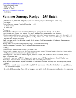
Life Safety Dampers Selection
and Application Manual
• Ceiling Radiation Dampers • Fire Dampers
• Combination Fire Smoke Dampers • Smoke Dampers
May
2014
1
Table of Contents
HOW TO USE THIS MANUAL DAMPER APPLICATION
3
• Fire Damper Application
• Smoke Damper Application
• Combination Fire Smoke Damper Application
• Corridor Ceiling Combination Fire Smoke Damper Application
DAMPER SELECTION
5
• Selection Process
• Key Points to Remember
ACTUATOR SELECTION
7
• Selection Process
• Actuator Mounting Options
• Key Points to Remember
SLEEVE REQUIREMENTS
9
• Sleeve Thickness
• Sleeve Length
• Key Points to Remember
SPACE REQUIREMENTS FOR PROPER INSTALLATION
10
• Key Points to Remember
DAMPER OPTIONS
11
• Control Options
• Security Bar Options
• Transition Options
• Key Points to Remember
INSTALLATION REQUIREMENTS
15
• Combination Fire Smoke Damper Installation
• Smoke Damper Installation
• Actuator Installation
• Damper / Actuator Maintenance
• Key Points to Remember
SPECIAL INSTALLATION CASES
17
• Maximum Damper Size Limitations
• AMCA Mullion System
• What if a Damper Can't be Installed per the Manufacturer's Instructions?
• What if a Damper Can't be Installed in the Wall?
• Steps to Take When an Unapproved Installation Must be Provided
CEILING RADIATION DAMPERS
19
• Ceiling Radiation Damper Application
• Key Points to Remember
CODES AND STANDARDS
•
•
•
•
Compliance with the Applicable Building Codes
The National Fire Protection Association
Code and Standard Making Organizations
Modifications to Life Safety Dampers
UL STANDARDS
MOST COMMONLY ASKED QUESTIONS
MODEL DEFINITION
DRIVE ARRANGEMENT DEFINITION
THE GREENHECK DIFFERENCE
2
21
23
25
26
27
27
HOW TO USE THIS MANUAL
This manual can be utilized in a variety of ways. It can be studied from cover to cover as a textbook on fire, smoke,
combination fire smoke dampers, and ceiling radiation dampers or it can be used as a reference on one or more
of the following topics:
•
•
•
•
•
Fire, smoke, or combination fire smoke damper applications
Selection of the correct damper and actuator
Damper and actuator installation requirements
Ceiling radiation dampers
Codes and standards that regulate and qualify fire, smoke, or combination fire smoke dampers
There are answers to a list of “Most Commonly Asked Questions” at the end of this manual and summaries of
“Key Points to Remember” at the end of each section.
DAMPER APPLICATION
Fire Damper Application
Fire dampers are required by all building codes to maintain the required
fire resistance ratings of walls, partitions, barriers and floors when they
are penetrated by air ducts or other air transfer openings. One of the
basic requirements of building fire protection is the compartmentation or
dividing up of buildings using fire rated walls, floors, or other partitioning
methods. This compartmentation concept is intended to contain any
fire to the compartment of fire origin and thereby minimize damage to
property and protect the lives of people living and/or working in the
building. A duct or ventilation opening in any of the fire rated partitions
would permit a fire to spread from the compartment of origin to adjoining
compartments or spaces. Fire dampers are installed in these duct or
ventilation openings. They close automatically upon detection of heat by
a heat-responsive device (usually by the melting of a fusible link at 165°F
[74°C]), blocking the opening and preventing the spread of fire into the
adjoining compartment.
Fire rated partitions contain fire
damage to the compartment of fire origin.
UL (Underwriters Laboratories) Classified fire dampers are tested to
UL Standard 555 “Fire Dampers”. They are always supplied with an
appropriate UL label. There are significant factors required that must be
considered when specifying a fire damper for a certain application. These
are:
Fire Resistance Ratings
Two fire resistance ratings are available: 1½ hours and 3 hours. Walls,
floors, or partitions with fire resistance ratings of 3 hours or more require
fire dampers with a 3 hour rating. Fire resistance ratings less than 3 hours
require 1½ hour rated fire dampers. (Reference 2012 International Building
Code, section 717.3.2).
Unprotected partition
Airflow Closure Ratings
Fire dampers can be either STATIC or DYNAMIC rated. STATIC rated fire
dampers have no airflow closure rating and can only be applied in HVAC
systems that are designed to shut down automatically in the event of a
fire. DYNAMIC rated fire dampers carry a UL 555 rating to close while
the HVAC system is running. DYNAMIC rated fire dampers carry both an
airflow velocity (ft/min) rating and a pressure differential rating (in. wg)
and should be selected to operate against the conditions they will see in
their application. DYNAMIC rated fire dampers are always an appropriate
selection.
Partition protected
by fire damper
3
Mounting Orientation
Fire dampers are required to pass a test for vertical mount and/or a test for
horizontal mount. Dampers need to be installed in the correct orientation
to ensure life safety and proper fire protection. Each vertical or horizontal
mount damper carries its own label. These mounting orientations are not
interchangeable.
Smoke Damper Application
Horizontal Label
Smoke dampers have two general applications. They may be applied in
a “Passive Smoke Control System” where they simply close and prevent
the circulation of air and smoke through a duct or ventilation opening in a
smoke barrier. They also may be applied as part of an “Engineered Smoke
Control System” designed to control the spread of smoke using walls and
floors as barriers and using the building’s HVAC system and/or dedicated
fans to create pressure differences. Higher pressures surround the fire
area and prevent the spread of smoke from the fire zone into other areas
of the building. Smoke dampers are motorized with electric or pneumatic
actuators and may be controlled by a smoke or heat detector signal, a fire
alarm signal, or by the building control system to accomplish the intent of
the design.
UL Classified smoke dampers are tested to UL Standard 555S “Smoke
Dampers” and are always supplied with an appropriate UL label. It is
necessary to determine which of the following ratings are required when
applying a UL Listed smoke damper:
Vertical Label
Return/
Exhaust
Fan
Supply
Fan
Typical Non-Smoke Zone
Combination Fire Smoke Damper Application
A combination fire smoke damper performs the function of both a fire
damper and a smoke damper. Building layouts and designs often combine
fire and smoke rated partitions and barriers requiring the installation of
both a fire damper and smoke damper at the same location. Combination
fire smoke dampers must be qualified under UL Standard 555 as a
fire damper AND under UL Standard 555S as a smoke damper. The
considerations listed above for both of these damper types apply to the
selection and application of combination fire smoke dampers.
Damper positioned to create positive pressurization
Typical Fire Smoke Zone
Damper positioned to create negative pressurization
Return/Exhaust Air
Supply Air
• Leakage: Class I (lowest leakage), Class II, or Class III (highest
leakage). The 2012 International Building Code (IBC), section
717.3.2 requires a minimum of leakage class II. Leakage class I
is recommended to provide the safest level of protection.
• Elevated Temperature: 250°F or 350°F (121°C or 177°C) is the
temperature at which the actuator must be able to operate the
damper and the temperature at which the leakage test is conducted.
Most often 350°F (177°C) is selected for the highest level of safety.
• Velocity and Pressure: UL 555S requires each smoke damper with
its installed actuator to be rated for operation to open against a
specific pressure differential (in. wg) and to close against a specific
velocity of airflow (ft/min). Dampers should be selected to operate at
the pressures and velocities they will see in their application, with a
minimum of 4 in. wg (1 kPa) and 2000 ft/min (10.2 m/s).
Typical Engineered Smoke Control System
Smoke is contained to the fire zone by higher
pressures in adjacent zones
Corridor Ceiling Fire Smoke Damper Application
UL has established a separate classification to list dampers for this
application. UL 555 and 555S qualification plus additional tests in actual
corridor ceiling construction are required by UL to classify a combination
fire smoke damper.
Typical Smoke Damper
4
DAMPER SELECTION
Selection Process
Five basic decisions are required to select a fire, smoke, or a combination
fire smoke damper. The process involves defining requirements for:
• Blade Style - Curtain, 3V, airfoil, or round blade styles
• Fire Resistance Rating - 1½ or 3 hours based on code
requirements and building design (2012 International
Building Code, section 717.3.2)
• Leakage Rating - Class I, II, or III (2012 International Building
Code, section 717.3.2, requires a minimum of Leakage Class II)
• Elevated Temperature Rating - 250°F or 350°F (121°C or 177°C)
2012 International Building Code, section 717.3.2, requires a
minimum of 250°F (121°C)
• Operational Ratings - Velocities and pressure differentials the
damper will see in its application
Interlocking Curtain
Blades
3V Blade
• Blade Style
Blade style decisions are based on application, velocity, and the pressure
required for your system. The curtain blade style is appropriate for fire
damper applications only and airflow velocities up to 4,000 ft/min (20.3
m/s). The 3V blade style is appropriate for use in airflow velocities up to
2,000 ft/min (10.2 m/s). Airfoil style blades are appropriate for use with
airflow velocities up to 4,000 ft/min (20.3 m/s). A round style blade is
appropriate for use in airflow velocities up to 3,000 ft/min (15.2 m/s) where
you need to connect to round ductwork or where minimum pressure drop
is desired. Pressure loss information is available at www.greenheck.com.
Steel Airfoil Blade
• Fire Resistance Rating
Fire and combination fire smoke dampers installed in walls, floors, or
partitions are required by the applicable building code to have a fire
resistance rating. Select a fire damper and combination fire smoke
damper with a 1½ hour rating for use with a wall, floor, or partition with a
less than 3 hour fire resistance rating. If the wall, floor, or partition has a
fire resistance rating of 3 hours or more, the damper must have a rating of
3 hours.
Extruded Aluminum Airfoil Blade
Minimum Damper Rating
(hours)
Type of Penetration
Less than 3 hour fire resistance
rated assemblies
1½
3 hour or greater fire resistance
rated assemblies
3
Round Blade
If the barrier is not required to have a fire resistance rating, then no
fire rating is required and a smoke damper may be selected (see 2012
International Building Code, section 717.5.2). Smoke dampers may be
required in corridor penetrations in accordance with 2012 International
Building Code 717.5.4.1.
• Leakage Rating
UL Standard 555S identifies three leakage classes as follows:
Leakage
Class
Maximum Leakage in cfm/ft2 Maximum Leakage in cmh/m2
@ 4 in. wg
@ 8 in. wg
@ 1 kPa
@ 2 kPa
Class I
8
11
146
201
Class II
20
28
366
512
Class III
80
112
1463
2048
Typical Fire Damper
Designers are generally advised to select the lowest leakage class.
5
Even though the 2012 edition of the International Building Code requires a
minimum of Leakage Class II, there are some applications where a higher
leakage class can be used. Leakage Class I (the lowest leakage) rated
dampers are available from most manufacturers ensuring appropriate
competition if Class I is selected.
• Elevated Temperature Rating
The purpose of a building Smoke Control System is to keep certain areas
of a building free from smoke during the early phases of a fire so building
occupants can safely evacuate and firefighters can more easily locate
and attack the fire. The UL 555S Elevated Temperature Rating is a 30
minute emergency rating to ensure the damper (and its' installed actuator)
can resist a short exposure to elevated temperature and still operate as
required. Although 250°F (121°C) is the minimum elevated temperature
rating, 350°F (177°C) is available for all Greenheck fire smoke damper
models at no additional cost. The 2012 International Building Code
(IBC) requires the minimum 250°F (121°C) rating. Modulating actuators
and extruded aluminum blade models are rated at 250°F (121°C). All
Greenheck FSD (combination fire smoke) dampers and SMD (smoke)
damper models are UL 555 and UL 555S rated to 350°F (177°C).
Typical Multi-Blade
Fire Damper
• Operational Rating
Operational ratings are dependent on the damper’s size and installed
actuator. Both UL 555 and UL 555S require a combination fire smoke
damper and its installed actuator be rated for a maximum airflow rate
(velocity in ft/min) through the open damper and a maximum pressure
(in. wg) across the closed damper. The installed actuator must operate
the damper open and close against these rated velocities and pressures.
Greenheck combination fire smoke dampers with 3V blades are rated up
to 2,000 ft/min (10.2 m/s) and pressure up to 6 in. wg (1.5 kPa). The airfoil
blade models are rated up to 4000 ft/min (20.3 m/s) and pressure up to 8
in. wg (2 kPa).
Typical Combination
Fire Smoke Damper
RRL and actuator act to close damper
when temperatures exceed thermostat
(165° - 350°F [74° - 177°C]) to protect
the duct from fire and smoke penetration.
Dynamic rated fire dampers are typically rated without actuators. Round,
curtain style fire, and multi-blade fire dampers meet the requirement of UL
555 with airflow rating up to 4,000 ft/min (20.3 m/s) and pressure up to
10 in. wg (2.5 kPa).
Considerations of blade style, fire resistance rating, and leakage rating
lead directly to the selection of an appropriate Greenheck fire, combination
fire smoke or smoke damper model. Once an appropriate damper model
has been selected, its elevated temperature and operational ratings
should be compared with the requirements for these ratings.
Typical Round Combination
Fire Smoke Damper
KEY POINTS TO REMEMBER
• Codes require fire dampers in most applications where the barrier being penetrated is required to have a
fire resistance rating of 2 hours or more. Code requirements vary. Always follow the requirements of the
applicable building code.
• Smoke dampers are required where a duct penetrates a smoke partition or barrier within a building, in a
corridor penetration AND when any damper performs a function in an engineered smoke control system.
• 1½ hour fire dampers appropriately protect walls, partitions, and barriers with fire resistance ratings less
than 3 hours. 3 hour fire dampers are required if a barrier’s fire resistance rating is 3 hours or more.
• STATIC rated fire dampers can be applied only if the HVAC system is automatically shut down in the event
of a fire emergency. DYNAMIC rated fire dampers can be applied in all HVAC systems.
• When selecting a fire or combination fire smoke damper there are five basic decisions which affect final
model selection: blade style, fire resistance rating, leakage rating, elevated temperature, and operational
ratings.
6
ACTUATOR SELECTION
A smoke damper’s function is to OPEN or CLOSE to either seal off an opening, or to create a pressure
difference to prevent the spread of smoke. The damper actuator drives the damper to OPEN or CLOSE. When
a smoke damper or a combination fire smoke damper is selected, a very important part of the process is the
selection of an appropriate damper actuator. Qualification of the damper under UL Standards 555 and 555S
involves testing both the damper and its installed actuator. This means the actuator must be selected from
the damper manufacturer’s list of actuators that have been tested with and are UL Listed for the smoke or
combination fire smoke damper model that will be furnished. Actuators must be furnished factory-installed by
the damper manufacturer.
Selection Process
Actuators may be ELECTRIC or PNEUMATIC. Damper size limitations are
based on the velocity of airflow through the open damper and the pressure
differential across the closed damper.
• Actuator Type
Select either ELECTRIC or PNEUMATIC actuators based on the type of
control system that will operate the dampers and any other appropriate
factors. Most electric actuators are available in 24VAC, 24VDC, 120VAC,
or 230VAC. Pneumatic actuators require 25 - 30 psi (172 - 207 kPa) control
air. Operation may be two position, three position, balancing or modulating
control. Consult Greenheck for other voltage, frequency, or control
requirements.
Electric Actuator
• Actuator Model
Each specific actuator model will have a series of maximum damper size
ratings depending on the damper model, airflow velocity through the open
damper, temperature rating required, and maximum pressure differential
across the closed damper. As an example, damper size limitations for two
of the more commonly used actuators installed to operate Greenheck’s
model FSD-311 (airfoil blade combination fire smoke damper) with a 4 in.
wg (1 kPa) maximum pressure differential are as follows:
Damper Actuator
Siemens 331-4551
(pneumatic)
Honeywell
MS4104, 4604, 8104
(24V, 120V, 230V electric)
Mounting
Location
Velocity
ft/min
(m/s)
Temperature
°F (°C)
Maximum Size
WxH
in. (mm)
External or
Internal
2000
(10.2)
350 (177)
24 x 24
(610 x 610)
External
3000
(15.2)
350 (177)
18 x 18
(457 x 457)
External or
Internal
2000
(10.2)
350 (177)
24 x 24
(610 x 610)
External
3000
(15.2)
350 (177)
18 x 18
(457 x 457)
Pneumatic Actuator
Greenheck damper representatives have or can obtain the necessary information to properly apply all actuators
that are UL Qualified for use with Greenheck combination fire smoke dampers. Greenheck’s Computer Aided
Product Selection (CAPS) program contains the necessary data and greatly simplifies actuator selection.
7
Actuator Mounting Options
Actuators must be factory mounted. Factory mounting options include external (on a damper sleeve or sideplate)
or internal. Internal actuator mounting (where the actuator is mounted inside a duct) should be avoided if
possible, as it increases the difficulty of actuator inspecting, testing, and servicing.
• Factory Mounting - External on a Sleeve
As all combination fire smoke dampers require a sleeve for proper
installation, the most practical choice is for the damper to be furnished
by the factory complete with a sleeve and the actuator installed on the
outside of the sleeve. This is the standard and recommended actuator
mounting option for combination fire smoke dampers.
• Factory Mounting - External on a Sideplate
Smoke dampers do not always require sleeves for proper installation.
External installation of the actuator can be provided using a sideplate
(usually the full height of the damper as illustrated). These dampers are
installed in a slotted duct section with the sideplate covering the slot in
the side of the duct. Full height sideplates may not be practical on large
smoke dampers (particularly multi-section assemblies).
• Factory Mounting - Internal
Most actuators can be mounted internally (in the airstream) to
accommodate those installations where space constraints prevent the
more desirable external installation. There are limitations on small sizes
with options (such as the TOR, RRL/OCI, OCI or PRV), which occupy much
of the available internal space.
Damper mounted in sleeve with
actuator externally mounted.
Damper with sideplate actuator
externally mounted.
Damper mounted in sleeve with
actuator internally mounted.
KEY POINTS TO REMEMBER
• Actuators may be electric or pneumatic and may be two position, three position, balancing or
modulating control.
• An actuator’s damper size rating is dependent on the airflow velocity and pressure difference for each
specific damper.
• The most practical way to supply combination fire smoke dampers is with a factory-furnished sleeve
with the actuator mounted externally.
• Sideplate external actuator mounting is available on smoke and combination fire smoke dampers.
8
SLEEVE REQUIREMENTS
All UL fire and combination fire smoke damper listings require that the damper be mounted in a sleeve of the
required gauge and length prior to installation. The sleeved damper is installed in the wall or floor opening and
retained as part of the structure by angles attached to the sleeve. The sleeved damper becomes part of the wall
(or floor) structure and ducts are attached to the sleeve. UL requires that connecting ducts terminate at each end
of the damper sleeve.
• Sleeve Thickness
Sleeve gauge or thickness requirements
depend on the size of the damper and on
the type of duct-to-sleeve connections
used. UL allows two types of duct-to-sleeve
connections: RIGID and BREAKAWAY.
A RIGID connection is, by UL’s definition,
any connection that has not been qualified
as a BREAKAWAY connection. A number
of qualified BREAKAWAY connections, as
well as procedures for qualifying additional
BREAKAWAY connections, are defined in
UL Standard 555. All qualified BREAKAWAY
connections must be described in the
damper manufacturer’s fire and combination
fire smoke damper installation instructions.
Table 1 provides minimum fire and
combination fire smoke damper sleeve
thickness requirements as defined by
UL 555.
• Sleeve Length
Table 1: Minimum Sleeve Thicknesses for
Fire/Combination Fire Smoke Dampers
Sleeve Gauge
Duct Dimension
Type of Duct to Sleeve
Connection Permitted
14 ga. (0.075 in.) 10 ga. (0.138 in.)
[2mm - 3.5mm]
All duct sizes
Rigid or
Breakaway
16 ga. (0.060 in.)
[1.5mm]
36 in. (914mm) max. width
24 in. (610mm) max. height
24 in. (610mm) diameter
Rigid or Breakaway
16 ga. (0.060 in.)
[1.5mm]
All duct sizes
18 ga. (0.048 in.)
[1.2mm]
85 in. (2159mm) wide and
over
20 ga. (0.036 in.)
[0.9mm]
55 in. - 84 in. wide
(1397mm - 2134mm)
22 ga. (.030 in.)
[0.76mm]
31 in. - 54 in. wide
(787mm - 1372mm)
24 ga. (0.024)
[0.6mm]
13 in. - 30 in. wide
(330mm - 762mm)
26 ga. (0.018 in.)
[0.46mm]
12 in. wide and under
(305mm)
Breakaway only
Sleeve thickness must not be less than the gauge of the connecting duct.
The required sleeve length depends on
UL Standard 555 requires all ducts to terminate at fire damper sleeves.
the thickness of the wall or floor being
penetrated, and the space constraints
imposed by the damper’s actuator, accessories, and options. UL
imposes the following maximum sleeve length restrictions for
combination fire smoke and multi-blade fire dampers: Sleeves may
not extend more than 6 in. (152 mm) beyond the wall or floor on the
Actuator and
accessories
non-actuator side (B dimension, Figure 1). On the actuator side of the
are mounted
in this
general area
opening (A dimension, Figure 1), the sleeve may extend 16 in. (406
mm). On fire dampers, sleeves shall extend a maximum of 6 in. (152
Damper
mm) beyond the wall or floor opening on each side. If the sleeve is
provided with an access door, it may extend 16 in. (406 mm) on the
side equipped with the access door. Sleeves must extend far enough
beyond each side of the wall or floor to accommodate the retaining
angles required for installation (usually 1½ in. [38 mm]) plus whatever
is required for the duct-to-sleeve connections (usually a minimum of
A
1½ in. [38 mm]). On the actuator side of the damper, the sleeve must
Tw
16 in. Max.
be long enough to accommodate the actuator and accessories (A
dimension, Figure 1).
Overall Sleeve Lengt h
B
6 in.
Max.
Lmin
Figure 1: Sleeve Length Considerations
9
Figure 2 provides a means
of estimating the minimum
required sleeve length.
Figure 2: Minimum Sleeve Length Equation
Lmin
=
A + B + Tw
Lmin
=
minimum sleeve length
A
Figure 3: Typical Sleeve Length Requirements
Wall or Floor Thickness
Inches (mm)
Sleeve Length Required
Inches (mm)
=
length of sleeve beyond wall
(actuator side)
4-6
(102 - 152)
16 - 21
(406 - 533)
B
=
length of sleeve beyond wall
(non-actuator side)
7 - 10
(178 - 254)
21 - 24
(533 - 610)
Tw
=
wall thickness
11 - 13
(279 - 330)
24 - 28
(610 - 711)
Figure 3 provides typical
sleeve lengths for given wall
thicknesses.
Greenheck’s standard and most economical sleeve lengths are 16, 21, and 24 inches (406, 533, and 610 mm).
KEY POINTS TO REMEMBER
• All fire and combination fire smoke dampers require sleeves for installation.
• The damper and sleeve are part of the wall. The ductwork terminates at each end of the damper sleeve.
• Damper size and RIGID or BREAKAWAY duct-to-sleeve connections determine the required sleeve
thickness. The sleeve thickness shall not be less than the thickness of the connecting duct.
SPACE REQUIREMENTS FOR PROPER INSTALLATION
When a combination fire smoke damper is being installed, it must fit in the space available with room for wiring
or piping. After the damper is installed, it must work properly and perform its important function for the life of the
building. The damper, its actuator, and any optional accessories must be accessible for inspection, testing, and
service (per NFPA 80, 90A, 92A, 101 and 105). Actuators and other components may require replacement as part
of a planned maintenance program. While space requirements are somewhat predictable, spending a little time
making sure everything will fit can eliminate many problems and save money for all concerned.
The damper actuator and optional accessories are normally externally
mounted on one side of the damper’s sleeve. It is
Greenheck’s standard practice for these items to be on
the right side of the sleeve. This is a “right hand mount”.
When specifically requested, they may be mounted on
the left side of the sleeve, as shown, which we call a “left
Retaining
Angle
hand mount”. As many combination fire smoke dampers
have a “top” or “this side up” designation, and cannot be
turned upside down, it is very desirable to clearly define
the right or left hand actuator mounting requirements
when the damper order is released for fabrication. A
capability unique to Greenheck's combination fire smoke
dampers allows dampers to be turned upside down (when
installed vertically or horizontally) to overcome unforeseen
clearance problems. Greenheck designed its UL Qualified
combination fire smoke dampers not to have a "top" or
"this side up" designation to provide flexibility for the
installing contractor.
Greenheck’s combination fire smoke damper product
submittal and our Computer Aided Product Selection
(CAPS) program includes dimensional information
describing space requirements for damper actuators and
optional accessories. If space above or below the damper
sleeve is limited, special note should be taken as some
standard actuator mountings require clearance in this area. In most cases,
10
Wall or Floor
Retaining
Angle
Sleeve
Duct
Represents space
allowance required for
externally mounted
actuator and controls
clearance problems can be accommodated if they are defined before production of the dampers. Clearance
problems discovered after the dampers are on the jobsite can be extremely costly.
Internal actuator mounting should be considered only as a last resort solution to clearance problems. Even with
internal actuator mounting, external clearances may still be required. Access to the actuator for wiring, piping,
inspection, and service must be provided. Internal mounting may not be available on smaller size dampers
because there simply is not enough room to fit the actuator inside the sleeve.
KEY POINTS TO REMEMBER
• Actuators and optional accessories occupy space outside of the combination fire smoke damper sleeve
or sideplate, and appropriate clearances are required.
• Actuators mounted externally will be right hand mounted as standard, but can be left hand mounted
upon request.
• Internal actuator mounting is not a good solution to lack of clearance and should not be used unless
there is no other solution.
DAMPER OPTIONS
Closure Device
Smoke and combination fire smoke dampers without options are fairly straight-forward devices. The damper
is linked to its actuator, which moves the damper to its open or closed position in response to signals from the
building control system, fire alarm system, smoke alarm system or the electric heat-responsive sensing device
on the damper itself.
Fire dampers and round combination fire smoke dampers are equipped
standard with a fusible link. Fusible links meet UL33 requirements.
Combination fire smoke dampers are equipped standard with a Reusable
Resettable Link (RRL), an electric heat-responsive sensing device. The
RRL has a fixed temperature setting (usually 165°F [74°C]) and performs
the same function as a fusible link, which is to sense an abnormally high
temperature (presumed to be caused by a fire) and allow the damper to
close to prevent the spread of fire and smoke. The sensor interrupts power
to the actuator, causing the actuator’s spring return mechanism to close
the damper. If the damper is equipped with a pneumatic actuator, a PRV
(pneumatic relief valve) or an EP switch (electro-pneumatic solenoid valve)
is used in conjunction with an RRL to control the pneumatic damper.
An advantage of the RRL is that it can be reset (by pushing a reset button
at the sensor), eliminating the need to replace a fusible link each time on
the damper. It is recommended that a careful inspection of the damper
and the electric sensor be made before resetting as exposure to actual fire
conditions may render these devices unusable. As UL requires that labeled
fire dampers be set up at the damper factory to close automatically upon
sensing an abnormally high temperature, the RRL can only be furnished
when the damper actuator is factory installed and wired to the electric
sensor before shipment. This feature is particularly desirable if periodic
testing requirements involve application of elevated temperature to the
thermostat (or heat sensing devices) to verify they will respond in the
proper manner to actual fire conditions.
RRL
RRL/OCI
11
When a combination fire smoke damper is equipped with a pneumatic
actuator, a PRV (Pneumatic Relief Valve) is used to exhaust air from a
pneumatic actuator when the 165°F (74°C), 212°F (100°C), or 350°F (177°C)
fusible link melts, allowing the damper blades to close. THE PRV OPTION
DOES NOT REQUIRE ANY ELECTRICAL POWER.
Smoke dampers are not equipped with RRL’s, PRV’s, or fusible links, and
operate only in response to alarm or control signals.
• Single-Point Wiring
In correlation with UL requirements, all actuators must be linked through
one heat responsive device to ensure a single event closing on multisection dampers. All actuators and accessories are wired to a single
junction box for a convenient single point wiring installation. This is
standard on all combination fire smoke dampers (FSD).
PRV
Blade Indication
• OCI Option (Open Closed Indication)
This option provides two switches, one set to close when the damper
blades are at their open position, and the other set to close when the
damper blades are at their closed position. These switches are physically
linked to a damper blade and therefore give a true representation of the
damper’s position. Normally these OCI switches are wired to indicator
lights (often located in the Fire Fighters’ Smoke Control Station), however,
they may be used for other purposes as required.
• Actuator End Switches
Actuator end switches are also commonly referred to as auxiliary switches.
These switches are internal to the actuator and perform the same function
as the OCI option. These switches are also normally wired to indicator
lights (at the Fire Fighter's Smoke Control Station), or used for other
purposes as required. The end switches are offered as an alternative to
the OCI option based on preference of the design engineer.
OCI
Temperature Override
An Engineered Smoke Control System may require the combination fire
smoke dampers to be open at a higher temperature than what is specified
in the building code (often required to close at 165°F [74°C]) to perform
its smoke control functions in a HVAC system. Most authorities agree
that fire dampers can be open during emergency periods so the HVAC
system can perform its smoke control functions as long as there is a
higher temperature limit (usually 350°F [177°C]) at which these dampers
will close and remain closed. All authorities do not agree that the code
required fire damper closure temperature of 165°F (74°C) may be waived
in favor of a higher temperature for smoke control applications. This dual
requirement for the combination fire smoke dampers to close at 165°F
(74°C) and yet to be open to allow smoke control system operation can
be accomplished by using an OVERRIDE OPTION. These override options
allow the 165°F (74°C) closure command to be overridden by a remote
electrical signal (reopening the damper) but also provide for the damper
to close automatically at a higher temperature usually 350°F (177°C) and
remain closed thereafter. The latest NFPA 90A Standard and 2012 IBC
permit the use of a single 350°F (177°C) closure control in combination fire
smoke dampers, eliminating the requirement to close these dampers at
165°F (74°C) and to reopen them for smoke control purposes.
12
TOR
• TOR Option (Temperature Limited Override Option)
The TOR Option incorporates two temperature sensing devices
(thermostats) with fixed settings (usually 165°F [74°C] and 350°F [177°C])
and eliminates the fusible link entirely (similar to the RRL option which
has only one sensor). The primary sensor (usually 165°F [74°C]) can
be bypassed by an external electrical signal allowing the damper to
reopen and remain open until the temperature reaches the setting of the
secondary sensor (usually 350°F [177°C]). When the temperature of the
secondary sensor is exceeded, the damper closes and remains closed
thereafter. Both sensors are of the manual reset type. After temperatures
have cooled down below the sensor set points, they can be reset by
pushing a reset button located at the sensor. Before resetting any sensor,
a careful inspection of the damper and the sensors should be made as
exposure to actual fire conditions may render these devices unusable.
This option requires factory installation of the damper actuator and
factory wiring of the electric sensor to meet UL requirements for fire
dampers. If the damper is equipped with a pneumatic actuator, an EP
switch (electro-pneumatic solenoid valve) is required in conjunction with
the TOR option. Additionally, the TOR Option incorporates two damper
blade position indicator switches which function as described under the
OCI option heading.
TOR
Testing Device
• Momentary or Toggle Test Switch
The momentary or toggle test switch cuts the power to the damper
actuator assembly and in turn closes the damper blades. It is used with
a combination fire smoke or smoke damper to test and cycle the damper
on location for both start-up testing and maintenance. This UL Qualified
assembly ships factory mounted and wired.
Momentary Test Switch
• GTS (Greenheck Test Switch)
Greenheck test switches are used in dynamic smoke management
systems containing combination fire smoke dampers and smoke dampers.
These switches provide an easy way to perform testing and maintenance
of motorized life safety dampers. All Greenheck test switches come with a
5 x 5 in. (127 x 127 mm) stainless steel plate.
GTS-1 and GTS-2 is a single control panel to be used on combination
fire smoke dampers equipped with TOR (Temperature Override Control).
GTS-1 control panel has a toggle switch with red indicator light for closed
damper, green for open damper. The GTS-1 is available factory-mounted
or shipped loose. GTS-2 has a key switch with red indicator light for
closed damper, green for open damper. The GTS-2 is available shipped
loose. The LED lights are replaceable.
GTS-1
GTS-3 is a control panel that can be used on combination fire smoke
dampers with RRL/OCI, TOR, or smoke damper with an OCI. This test
switch has red/green open and close indicator lights with momentary test
switch. The GTS-3 is available factory-mounted or ship loose.
GTS-2
GTS-4 is a control panel that can be used with combination fire smoke
dampers with RRL/OCI, TOR, or smoke damper with an OCI. This test
switch has red/green open and close indicator lights only. The GTS-4 is
available factory-mounted or ship loose.
GTS-3
GTS-4
13
Smoke Detectors
A smoke detector’s purpose is to sample air currents passing through a
duct and upon alarm, provide management of fans, blowers, combination
fire smoke dampers and smoke dampers.
• Photoelectric Smoke Detector
D4120 Smoke Detector
The photoelectric smoke detector samples air currents passing through
a duct and provides dependable performance for management of smoke
and combination fire smoke dampers. There are two smoke detectors
available:
1. The DH-98-P is rated for air velocities from 300 - 4000 ft/min
(1.5 - 20.3 m/s).
2. The D4120 is rated for air velocities from 100 - 4000 ft/min
(0.5 - 20.3 m/s)
These smoke detectors can either be factory-mounted and wired or
shipped loose.
DH-98-P
DH
98 P Smoke
S
k D
Detector
• No Flow Smoke Detector
The no flow smoke detector is rated for systems without a minimum
operating velocity. This smoke detector is rated for air velocities 0 to 3000
ft/min (0 to 15.2 m/s) and is mounted internally to the damper sleeve.
It can be used on dampers with a maximum of two actuators. No flow
smoke detectors have a built-in test switch.
Security Bars
No Flow
Smoke Detector
When a specification requires security bars to be installed with the
damper, they can be shipped factory assembled. Installation of security
bars into dampers reduces security risks and reinforces the equipment.
Security bars maintain the UL Classification for all products and are
welded into the sleeve. Two types of security bars are available:
• Cross bar - round steel bars placed horizontal and vertical on center,
based on customer selection or
• Punched mid bar - round steel bars placed vertical on center, based
on customer selection, with flat mid-bars placed horizontal on
dampers wider than 24 inches (610 mm).
Transition
When square or rectangular smoke and combination fire smoke dampers
are required to be installed with round, square, rectangular, or oval
ductwork, they must be supplied with the appropriate transition option.
Square or rectangular dampers are constructed 0, 1, or 2 inches (0, 25, or
51 mm) larger than the duct dimensions (depending on the transition type)
and provided with a factory sleeve. The sleeve is transitioned at each end
to the appropriate round, square, rectangular or oval duct size. Square or
rectangular dampers can also be transitioned in this manner to achieve a
higher free area.
Square or rectangular fire dampers have six transitions available: B, B2,
C, CO, CR, and R. Square or rectangular dampers are constructed 0, 1,
or 2 inches (0, 25, 51 mm) larger than the duct dimensions (depending on
the transition type). Transitions are constructed the same way except no
sleeve is required.
True round fire, combination fire smoke, and smoke dampers are available
when round ductwork is used in diameters up to 24 inches (610 mm).
14
Security Bars
Type CR
Type R
Type B/B2
Type CO
Type O
Type C
Transitions
Quick Connect Breakaway Connection
Quick connect breakaway connection
Greenheck was the first manufacturer to successfully UL Qualify a
universal breakaway duct connection that is compatible with TDC, TDF,
Ductmate®, Nexus or Ward flange systems. The universal breakaway
connection is available on fire, smoke, and combination fire smoke
dampers. Dampers can be ordered with breakaway connection three
different ways:
• Universal flange attached to one end of the sleeve
• Universal flange attached to both ends of the sleeve
• One end attached and one shipped loose
Factory Mounted Retaining Angle
Factory mounted retaining angle
Retaining angles can be ordered factory mounted by Greenheck in four
different ways:
• Single Fastened - one retaining angle mounted
• Single Wrapped - one retaining angle wrapped around the damper
sleeve and wire tied
• Double Wrapped - the same feature as single wrapped, but with two
sets of retaining angles
• Fastened & Wrapped - one retaining angle fastened and one angle
wrapped around the damper
Factory Mounted Access Door
Access door factory mounted
According to NFPA 80 (2007 edition) & NFPA 90A (2002 edition), an access
door is required in air ducts adjacent to each fire, smoke, or combination
fire smoke damper for maintenance and inspection. Greenheck can install
the access door in the sleeve to save on labor costs in the field.
KEY POINTS TO REMEMBER
• The OCI option provides two switches to indicate that a damper is open or closed. Auxiliary switches in the
actuator may also be used to determine damper open/close.
• The TOR option allows overriding or bypassing of the primary fire damper closure signal allowing the
combination fire smoke damper to reopen and the HVAC system to perform smoke control functions.
• If the damper is equipped with a pneumatic actuator, an EP switch is required with an appropriate electric
power circuit, to allow the electric thermostat (RRL or TOR) to control the actuator. An optional
PRV may be ordered in lieu of the standard RRL / EP switch closure system to eliminate the need for
120VAC or 24VAC power.
• Square or rectangular combination fire smoke or smoke dampers to be installed with round or oval
ductwork require the appropriate transition options.
INSTALLATION REQUIREMENTS
The 2012 IBC (International Building Code), section 717.2 states the following, "Fire dampers, smoke dampers,
combination fire/smoke dampers and ceiling radiation dampers located within air distribution and smoke control
systems shall be installed in accordance with the requirements of this section, the manufacturer's installation
instructions and the dampers' listing."
UL requires all fire and combination fire smoke damper manufacturers to publish specific damper installation
instructions detailing the required installation methods and procedures to properly install each specific model of
damper. These instructions must be followed to maintain the validity of the damper’s UL Listing. A copy of the
appropriate installation instruction(s) is included with each shipment of UL Listed fire, smoke, or combination
fire smoke dampers. Installation requirements may differ between damper manufacturers as a manufacturer
may qualify alternate installation methods by conducting additional tests at UL. Dampers must be installed in
accordance with instructions published by the company that actually manufactured the dampers.
15
Combination Fire Smoke Damper Installation
Combination fire smoke damper installation instructions encompass the
following requirements:
• Clearances required between damper sleeves and wall or floor
openings - Clearances of 1/8 in. (3 mm) per foot of damper width
or height are normally required for galvanized steel dampers, with
a minimum of ¼ in. (6 mm) and a maximum of 1½ inches (38 mm).
On true round dampers, the wall/floor opening must be a minimum
of 7/8 in. (22 mm) larger than the outside diameter of the damper.
1/4 inch
minimum
total
clearance
(see Section 1)
Actuator and
accessories
are mounted
in this
general area
• Sleeve requirements - Sleeve thickness requirements depend on
damper size and type of duct-to-sleeve connection used. Sleeve
length restrictions also apply. See pages 8 and 9 or installation
instructions for details.
Sealant
Sealant
• Fastening the damper to the sleeve - Instructions will show method
of attachment and spacing of attachments.
Tw
• Installing damper/sleeve assembly in wall and floor openings Installation options for securing the damper to wall or floor openings
depend on the following factors: model, size, mounting orientation,
and wall or floor construction. Single side or two side retaining
angle options are available. Check with local authority having
jurisdiction. See installation instructions for detail.
• Sealing of the damper frame to the ductwork - Smoke and
combination fire smoke dampers must have the joint
between the damper frame and duct sealed to prevent
unwanted air leakage.
Ductwork
• Duct-to-sleeve connections - These can be rigid or
breakaway type. Breakaway connections should be
described in detail in the manufacturer’s installation
instructions (see page 8).
Damper
Smoke Damper Installation
Sealant
Smoke damper installation instructions encompass the following
requirements:
• Location of the damper in the ductwork - Damper centerline
must be located no more than 24 in. (610 mm) from the
protected smoke barrier.
Smoke
Barrier
Duct
Outlet
24 in.
maximum
• How to attach damper to the ductwork - Instructions will show
method of attachment and spacing of attachments.
• Sealing of the damper frame to the ductwork - The joint between
damper frame and duct must be sealed to prevent unwanted
air leakage.
Actuator Installation
Factory installation of actuators on smoke and combination fire smoke dampers is required by UL 555S.
Maintenance helps to ensure that a system can be trusted to perform its function in an emergency.
Wiring or Piping of Smoke and Combination Fire Smoke Damper Actuators
Electrical and/or pneumatic connections to smoke and combination fire smoke damper actuators should be
made in accordance with control schematics and diagrams developed specifically for the job or project and that
comply with the project specifications. Refer to the latest version of NFPA 70, National Electrical Code.
Damper and Actuator Maintenance
Smoke Control Systems maintenance schedules should include, as a minimum, periodic testing and cycling of
system components. Dampers and their actuator(s) must be maintained, cycled and tested as a minimum in
accordance to:
16
• The latest editions of NFPA 80, 90A, 92, 101, and 105
• Actuator manufacturer's recommendations
• Local codes
• Other applicable industry standards
KEY POINTS TO REMEMBER
• Fire and combination fire smoke dampers must be installed in accordance with their manufacturer’s
installation instructions for the specific damper model.
• Smoke dampers centerline may be installed in ductwork within 24 in. (610 mm) of the smoke barrier
they are intended to protect. Combination fire smoke dampers must be installed within and as part of,
the fire rated barrier using sleeves and retaining angles, unless they are specifically tested otherwise
(OFSD models).
• Required sleeve gauge or thickness depends on the damper size and the type of “duct-to-sleeve
connections” used. If connections are “rigid”, the sleeve must be 16 ga. (1.5 mm) minimum
(14 ga. [1.9 mm] for larger dampers). If connections are “breakaway”, the sleeve can be the same as the
gauge of the connecting ductwork (see pages 8 and 9 for specific requirements).
• Factory installed combination fire smoke and smoke damper actuators are required by UL 555S.
• Maintenance of engineered life safety systems should include periodic cycling and testing of dampers
and actuators in that system. Refer to industry codes and standards (such as NFPA 80, 90A, 92A, 101,
and 105), as well as component manufacturers for specific recommendations.
SPECIAL INSTALLATION CASES
Maximum Damper Size Limitations
The maximum size opening that can be protected by any manufacturer’s fire, smoke, or combination fire
smoke damper is specifically stated in the manufacturer’s UL Listing. These listings, which can be found on
UL’s website (www.ul.com) under the category EMME, provide both the maximum single-section size and the
maximum multiple-section size of a damper model. If no multiple-section size is listed, the damper is limited
strictly to single-section applications.
The maximum damper sizes found in the UL Listings are based on tests conducted in accordance with UL
Standard 555 (fire dampers) and UL Standard 555S (smoke dampers); combination fire smoke dampers are
subject to both UL Standards 555 and 555S. Filling openings larger than the maximum tested damper size is
not approved by UL unless the opening requires only a static rated fire damper. Oversized openings in dynamic
systems cannot be divided into smaller sections using support mullions. As always, the authority having
jurisdiction can decide whether or not to approve an installation.
AMCA Mullion System - For Static Fire Dampers Only
The Air Movement and Control Association (AMCA) International, Inc., the
damper industry trade association, in cooperation with the Sheet Metal
and Air Conditioning Contractors' National Association (SMACNA), have
developed a steel mullion system that allows the division of large wall
openings so that multiple dampers may be installed within the overall
wall opening. These steel mullions are designed to be fabricated by any
commercial sheet metal shop. They are approved for use in masonry or
concrete block walls from 7 to 12 in. (178 to 305 mm) thick. AMCA mullions
can be used horizontally to divide a wall opening up to 120 in. (3048 mm)
high or vertically to divide a wall opening of any size. Both vertical and
horizontal mullions can be used in a single opening. A typical detail of an
AMCA mullion is shown in this section. Mullion construction, application,
and limitations are shown in greater detail in Greenheck’s Mullion
Installation Instructions.
Formed Section View
(2 required)
33 8
7
¾
2
C-4
8
2
C = Wall Thickness
SPECIAL NOTE: AMCA mullions may only be used with static rated fire
damper assemblies. They cannot be used to install combination fire
smoke dampers in wall openings that exceed the maximum UL Approved
size for the combination fire smoke damper model being installed.
17
What if a Damper Cannot be Installed per the
Manufacturers Installation Instructions?
Assembled View
The proper approach in these instances is to propose a solution that is
based on sound engineering judgement and have the solution evaluated
and approved by the appropriate authority having jurisdiction (usually the
building code official responsible for administering the building code that
applies).
There are a number of resources available to consult when looking for a
sensible solution to a fire smoke damper installation problem. Here are a
few suggestions:
• Has this situation been encountered before and if so, how was it
handled? Ask the building code inspector or official.
3½
D
3/16-inch blind rivet (stl.) or
3/4-inch long intermittent welds
12 inches on center
6-inch maximum from both ends,
both sides of assembly.
• Greenheck's damper representatives are well informed as to what
alternate fire, smoke, combination fire smoke damper installation
methods have been approved in their territory.
2
• Greenheck will often have knowledge of alternative installation
methods that have been approved by other authorities having
jurisdiction. Also our experience in conducting UL fire tests allows us
to make suggestions based on actual test experience. Greenheck's
Damper representatives should be contacted for this type of
information.
2
H
H
• Look in the SMACNA Fire, Smoke, and Radiation Damper Installation
Guide for HVAC Systems. This publication illustrates many fire
smoke damper installation situations and includes suggested
alternate methods for consideration.
3/16-inch
typical rivet
location
3¼
Cap End Plate
(2 required)
Formed Section
End View
Wall Mullion Cap
Assembled View
Weld
H
E/8
E/4
E
E/4
E/4
3¼
E/8
Detail B-B
¾
-inch diameter (12 holes)
1½
6
Side View
1½
¾
F
End View
½ 1
Top View
1
One or two piece
End Plate
Center Channel
H
3¼
Weld
Side View
E
End View
18
What if a Damper Cannot be Installed in the Wall?
Steel stud
Greenheck has tested and qualified fire and combination fire smoke
damper for installation out of the plane of the wall (models OFD, ODFD,
& OFSD). This damper series is designed to allow 'through the grille'
access to actuator and controls. Model OFSD series dampers meet all
requirements of UL 555 and UL 555S.
Steps to Take When an Unapproved Installation
Must be Provided
1. Identify the problem and be ready to explain why an approved
installation cannot be made.
#10 sheet metal screws
spaced 6 inches on center
and a maximum of 2 inches
from the corners (minimum
of two screws per side).
Screw into rear portion of
the studs so as to avoid
space conflicts with the
grille assembly.
5/8 x 1 in. 16 gauge angles
minimum (refer to Section 4)
2. Research the alternate installation methods that may be applicable
and select a practical alternative that provides relative equivalency
based on engineering principles.
Factory supplied
thermal blanket
3. Illustrate your proposed alternative and discuss it with the damper
manufacturer (or representative), job design engineer, or both.
Grille
(supplied by others)
Obtain an agreement that it is an acceptable alternative.
4. Submit your alternative damper installation to the authority having
jurisdiction and obtain formal approval. Only the authority having
jurisdiction can approve an alternative combination fire smoke
damper installation. It is usually much easier to obtain approval
before a damper has been installed. After an installation has been
rejected by the inspector, it is often quite difficult to obtain approval.
7½ in.
maximum
Fire damper or
combination
fire smoke damper
Duct terminates
CEILING RADIATION DAMPERS
Ceiling Radiation Damper Application
Ceiling radiation dampers (also called ceiling dampers) are designed to protect openings in the ceiling membrane
of rated floor/ceiling and roof/ceiling assemblies. Ceiling dampers close upon the activation of a temperature
response device designed to release at a selected temperature (this is usually a 165°F ( 74°C) fusible link).
There are two general applications for UL classified ceiling dampers:
1. The first is in rated floor/ceiling or roof/ceiling
assemblies that were tested with and are now
listed with generic hinged-door-type ceiling
dampers. Most floor/ceiling and roof/ceiling
designs listed with hinged-door-type dampers
utilize acoustical ceiling tiles as their ceiling
membrane and have non-combustible structural
members (i.e. they do not use wood trusses or
joists). Dampers designed to take the place of a
hinged-door-type ceiling damper are evaluated
per UL 555C. Any UL 555C classified damper
may be used in these applications. However,
ceiling dampers may not be used in floor/ceiling
or roof/ceiling designs that are not specifically
listed with a generic hinged-door-type ceiling
dampers as part of their design.
Typical floor/ceiling assembly with a
generic hinged door type damper
19
2. The second application is in rated floor/ceiling or
roof/ceilings designs that were tested with and
are now listed with a specific, proprietary, damper
design. These floor/ceiling and roof/ceilings
designs typically have gypsum board ceiling
membranes and combustible structural members
(i.e. wood trusses or wood joists). Dampers
designed to be used in specific floor/ceiling or
roof/ceilings designs are evaluated per UL 263.
Although these floor/ceiling and roof/ceilings
designs are listed with specific damper models,
there are often designs with identical or nearly
identical construction that are listed with different
damper models.
Typical floor/ceiling assembly
with wood joist
In summary, the first step in determining the appropriate
ceiling damper for a given application should be to review
its listed design in the UL Fire Resistance Directory (or
equivalent directory). The floor/ceiling or roof/ceiling
design will either be listed for use with a generic hinge
door type damper (in which case any UL 555C classified
ceiling damper may be used), a proprietary damper
model, or with no allowable damper penetrations.
Typical floor/ceiling assembly
with wood truss
KEY POINTS TO REMEMBER
• Ceiling radiation dampers must be installed in accordance with their manufacturer’s installation
instructions for the specific damper model.
• Ceiling radiation dampers used in lieu of hinged door type dampers are tested to ANSI/UL 555C.
• Ceiling radiation dampers used in proprietary ceiling designs are tested to ANSI/UL 263.
• For field or design modifications, reference the Guide Information in The Fire Resistance Directory
Volume 1.
20
CODE AND STANDARD MAKING ORGANIZATIONS INFLUENCING FIRE
SMOKE DAMPER APPLICATION AND USE
Organization
ICC
International Code Council, Inc.
500 New Jersey Ave, NW, 6th Floor
Washington, D.C. 20001
Phone: 1-888-422-7233
www.iccsafe.org
ICBO
International Conference of Building
Officials
5360 Workman Mill Road
Whittier, CA 90601-2298
Phone: (562) 699-0541
NFPA
National Fire Protection Association
1 Batterymarch Park
Quincy, MA 02269-9101
Phone: (617) 770-3000
www.nfpa.org
Applicable Codes, Standards, Publications
• International Building Code (IBC)
- Uniform Building Code
- National Building Code
- Standard Building Code
• International Mechanical Code (IMC)
• Uniform Mechanical Code (UMC)
• NFPA 80: Fire Doors & Other Opening Protectives
• NFPA 90A: Installation of Air Conditioning & Ventilating Systems
• NFPA 92A/92B: Smoke Control Management Systems in Malls,
Atria, & Large Areas
• NFPA 101: Life Safety Code
• NFPA 105: Standard For The Installation of Smoke Door Assemblies
UL
Underwriters Laboratories, Inc.
333 Pfingsten Road
Northbrook, IL 60062-2096
Phone: (847) 272-8000
www.ul.com
ASHRAE
American Society of Heating,
Refrigerating, & Air Conditioning
Engineers, Inc.
1791 Tullie Circle, N.E.
Atlanta, GA 30329
Phone: (404) 636-8400
www.ashrae.org
SMACNA
Sheet Metal and Air Conditioning
Contractors' National
Association, Inc.
4201 Lafeyette Center Drive
Chantilly, VA 22021-1209
Phone: (703) 803-2980
www.smacna.org
AMCA
Air Movement and Control
Association International, Inc.
30 W. University Drive
Arlington Heights, IL 60004-1893
Phone: (708) 394-0150
www.amca.org
• UL 555: Fire Rated Dampers
• UL 555S: Smoke Dampers
• UL 555C: Ceiling Radiation Dampers
• UL Fire Resistance Directory
• ASHRAE Handbook
• Design of Smoke Management Systems
• Commissioning Smoke Management Systems
• Fire, Smoke, & Radiation Damper Installation Guide For HVAC
Systems
• HVAC Duct Construction Standards
• Publication 503-03: Fire, Ceiling Radiation, Smoke, Fire/Smoke
Dampers Application Manual
• Standard 500D: Laboratory Methods of Testing Dampers For
Rating
• Publication 511: Certified Ratings Program for Air Control Devices
21
CODES AND STANDARDS
The terms “code" and “standard" are often used interchangeably but there is a fine point of difference. A code
is a set of regulations and requirements written in appropriate language with the expectation that it will become
law. A code is enacted into law when it is adopted by formal action of a governing body or other authority
having jurisdiction.
A standard is not necessarily written with the expectation that it will be adopted by some authority having
jurisdiction and become law. Rather, a standard is intended to establish a defined level of performance or
requirements, and often includes a listing of the necessary tests and qualifications for compliance with the
standard. Codes often reference standards making them a part of the referencing code. For example, the 2012
International Building Code references UL Standard 555 as the appropriate standard for qualifying fire dampers
for use under the International Building Code.
Compliance with the Applicable Building Codes
is Mandatory
If a state, city, or other authority having jurisdiction has adopted one or
more codes governing construction within that jurisdiction, these codes
are the law and must be followed. As there are many code documents in
existence that have not been adopted by every authority with jurisdiction,
it is important that both the designer and contractor know exactly what
codes are applicable to the building in question.
In 1997, representatives of SCBBI, BOCA, and ICBO, by appointment
of the International Code Council (ICC), began developing the latest
significant body of code, the International Building Code. The intent of
the International Building Code is to provide “a comprehensive set of
regulations for building systems consistent with and inclusive of the
scope of the existing model codes” (2012 International Building Code,
International Code Council, 2012, p. iii). The existing model codes
encompassed by the IBC are the Uniform Building Code,
the National Building Code, and the Standard Building Code.
The subject of codes and standards cannot be treated in any depth in the
space available in this manual. See installation instructions and installation
supplements for specific information.
The National Fire Protection Association
The National Fire Protection Association merits special mention because
of its significance as a standard writing and trendsetting organization in
the fire and life safety arena. NFPA, a non-profit membership organization
founded in 1896, brings together all interested parties to promote safety
from fire, electricity, and related hazards through research, codes and
standards, technical services, and public education. Many of NFPA’s
Codes and Standards provide the basis for model building code
requirements or actually become a part of these codes. New concepts
and other changes in various NFPA Standards are usually adopted by the
several model building codes during the code review and revision process.
UL STANDARDS FOR TESTING AND RATING OF FIRE, SMOKE,
COMBINATION FIRE SMOKE AND CEILING RADIATION DAMPERS
Two UL Standards provide the basis for testing, qualifying, and rating fire, smoke and combination fire smoke
dampers. These two UL Standards are:
UL 555 Fire Dampers
UL 555S Smoke Dampers
Here is a summary of the major tests required to qualify dampers to these standards:
22
• Operational Reliability Cycle Test (UL 555S)
Fire smoke dampers intended for operation by gravity or spring
force (not driven by an actuator) must be cycled open and
closed 250 times. Fire smoke dampers that are driven by an
electric or pneumatic actuator must be cycled open and closed
(by their actuator) 20,000 times. In addition to the 20,000 full
stroke cycles, if the fire smoke damper is also intended for
use as a volume control damper, it must be cycled open and
closed (by its modulating actuator) 100,000 repositioning cycles.
These operational cycling tests are accomplished prior to the
temperature degradation and leakage tests (described below)
and ensure that the damper will function reliably after
repeated operations.
2400
1315.6
2200
1204.4
2000
1093.3
1800
962.2
1600
871.1
1400
760.0
1200
648.8
1000
537.8
800
426.7
600
315.6
400
204.4
200
93.3
0
Degrees Celsius
Time-Temperature Curve
Degrees Fahrenheit
• Fire Endurance Test and Hose Stream Test (UL 555)
Dampers are exposed to a standard test fire for a period of
either 1½ or 3 hours. This standard test fire is controlled to
follow the time temperature curve illustrated. Immediately after
conclusion of this fire test, the dampers are subjected to a
high pressure hose stream test during which water, at a nozzle
pressure of 30 psi (207 kPa) for 1½ hour dampers and 45 psi
(310 kPa) for 3 hour dampers, is applied to the dampers from
a distance of 20 feet (6 meters). The hose stream test provides
an extreme shock that ensures the dampers are structurally
strong enough to withstand the rigors of the most severe fire
conditions.
-17.8
0
1
2
3
4
Hours
5
6
7
8
• Salt Spray Exposure Test (UL 555 & UL 555S)
A damper sample is exposed to salt spray in a test chamber for a period of 120 hours. After this exposure,
the damper must close (and latch if a latch is provided). This test demonstrates a damper’s ability to function
after a more severe fouling than the damper is likely to experience during its intended application.
• Operational Performance Test (UL 555 & UL 555S)
A damper is subjected to airflows and pressures, and must demonstrate its ability to operate in the manner
expected by its configuration and intended application. Smoke and combination fire smoke damper
actuators must operate the dampers open and closed three times and combination fire smoke dampers
must also close as they would if their heat responsive device (RRL or fusible link) would operate. A damper
model’s airflow velocity and differential pressure ratings are based on the velocity and pressure conditions
against which the damper demonstrates its ability to operate.
• Temperature Degradation and Cycling Test
(UL 555 & UL 555S)
A damper with an actuator that has previously been subjected to the OPERATIONAL RELIABILITY CYCLE
TEST (described above) is exposed to an elevated temperature of 250°F (121°C) minimum (or higher in
multiples of 100°F [38°C]) for a period of 30 minutes. After 30 minutes exposure and while still at the elevated
temperature, the damper actuator must operate the damper open and closed three times. Time of operation
cannot exceed 75 seconds for any of the open or closed operations.
• Leakage Test (UL 555S)
At least three damper sizes of each model being tested (minimum width by maximum height, maximum
width by minimum height, and maximum width by maximum height) that have previously been subjected to
both the OPERATIONAL RELIABILITY CYCLE TEST and the TEMPERATURE DEGRADATION AND CYCLING
TEST must be tested for leakage. The minimum airflow and pressure ratings of dampers shall be 2000 ft/
min (10.2 m/s) and 4 in. wg. (1 kPa). Ratings shall be set in 1000 ft/min (5 m/s) increments from the minimum
airflow and in 2 in. wg (0.5 kPa) increments from the minimum pressure. Leakage testing must be conducted
at 400 ft/min (2 m/s) higher than the rated airflow and 0.5 in. wg (.1 kPa) higher than the rated pressure. A
damper’s leakage rating is based on the worst-case performance of the three damper sizes tested. See page
5 of this manual for an explanation of damper leakage ratings.
23
UL STANDARDS FOR TESTING AND RATING OF FIRE, SMOKE,
COMBINATION FIRE SMOKE AND CEILING RADIATION DAMPERS
UL 555C Ceiling Radiation Dampers
Here is a summary of the major tests required to qualify dampers to these standards:
• Fire Endurance Test (UL 555C)
Ceiling dampers are installed in a type of ceiling previously tested in a rated fire resistive floor-ceiling or
roof-ceiling assembly for 4 hours. Each test assembly includes a reference damper installed in a similar
construction. This standard test is controlled to follow the time temperature curve. The average temperatures
in the concealed space above the ceiling of the assembly of the ceiling dampers shall not exceed the
average temperature of the reference damper. The closing of the ceiling radiation damper is not to cause
disruption of the ceiling membrane during the fire test.
• Closing Reliability Test (UL 555C)
Ceiling dampers must close and latch (if a latch is provided) automatically from the open position during
each of 250 operations throughout the test and show no evidence of damage which impairs the fire
performance of the ceiling damper or ceiling air diffuser.
• Salt Spray Exposure Test (UL 555C)
The test sample is to be installed in a test chamber with the damper open and is to be supported in the
position of intended use. It is then exposed to salt spray for 120 hours. At the end of the test, the damper is
removed from the chamber and allowed to dry for a minimum of 24 hours at room temperature. The sample is
then placed in its intended mounting position and tested for closing and latching (if a latch is provided).
• Spring Closing Force Test (UL 555C)
A spring operated ceiling damper is to employ a spring or springs capable of exerting a force of 2 1/2 times
that is required to close the damper. The force is measured at a series of positions from fully open to closed.
MODIFICATIONS TO LIFE SAFETY DAMPERS
Field Modifications
The UL mark applies to the product as it is originally manufactured when shipped from the factory. UL does
not know what the effect of a modification may have on the safety of the product or the continued validity
of the UL certification mark unless the field modifications have been specifically investigated by UL. Unless
UL investigates a modified product, UL cannot indicate that the product continues to meet UL's safety
requirements.
Design Modifications
Careful considerations need to be given to alterations or modifications of the fire resistance assemblies.
When field issues arise, it is recommended the first contact for assistance be the technical staff provided by
the product manufacturer noted for the design. Users of fire resistance assemblies are advised to consult the
general Guide Information for each product category and each group of assemblies. The Guide Information
includes specifics concerning alternate materials and alternate methods of construction.
Contacting UL
UL provides assistance to the users of fire resistance assemblies and products, which includes clarification of
the published information.
UL also provides a service to investigate modifications to the fire resistance assemblies when requested by the
design submitter. Requests for clarification should describe the change and include drawings, if necessary.
Requests for clarifications or investigations can be made by contacting UL at:
• Phone 1-877-ULHELPS (1-877-854-3577) ext. 49590
• Email: [email protected] or
• UL's website: www.ul.com.
24
MOST COMMONLY ASKED QUESTIONS
Q. Are pneumatic actuators available on smoke and combination fire smoke dampers?
A. Smoke and combination fire smoke dampers are available with pneumatic or electric actuators (internal or
external mount).
Reference: Actuator Selection - Page 7
Q. Does the smoke and combination fire smoke damper actuator have to be factory mounted
by the damper manufacturer?
A. Yes. The 7th Edition of UL 555 and 4th Edition of UL 555S require all actuators on smoke and combination fire
smoke dampers to be factory mounted.
Reference: Actuator Mounting Options - Page 7, Actuator Installation - Page 15
Q. Are there any specific sleeve gauge requirements for combination fire smoke damper
installation?
A. Sleeve gauge or thickness requirements depend on damper size and the type of duct-to-sleeve connections used.
Reference: Sleeve Requirements - Page 8
Q. Is there any approved way of installing combination fire smoke dampers in openings that
are larger than the maximum UL Listed damper sizes?
A. There is no limit on the size of a static fire damper assembly made using approved section sizes. However, when
installing combination fire smoke dampers, smoke dampers and dynamic fire dampers, AMCA mullions cannot be
used to divide wall openings that exceed the maximum UL Approved size for the model being installed.
Reference: What if a Damper Cannot be Installed Per the Manufacturer’s Installation Instructions? Page 17, AMCA Mullion System - Page 16
Q. How much space outside the damper sleeve is required to accommodate the actuator
installation? Can the actuators be installed inside the sleeve to eliminate external space
requirements?
A. Clearance requirements for externally mounted actuators vary with actuator type. Enough space should
be provided to allow for connection of wiring or piping and the replacement of the actuator and/or control
components. If clearance is potentially a problem, the damper manufacturer should be contacted for specific
clearance requirements. Installing the actuators internally should be considered only as a last resort, as it creates
wiring/piping and service difficulties.
Reference: Space Required for Actuators for Proper Installation? - Page 10
Q. How should combination fire smoke dampers be installed?
A. Combination fire smoke dampers must always be installed in accordance with the manufacturer’s
installation instructions.
References: Installation Requirements - Page 14, What if a Damper Can't Be Installed Per the
Manufacturer's Installation Instructions? - Page 17
Q. Is there any fire, smoke or combination fire smoke dampers that can be used in corrosive
environment applications?
A. Greenheck has Severe Environment dampers that are constructed out of 316 stainless steel for this application.
References: Model Definition - Damper Model Number Code - Page 22, Severe Environment Dampers
catalog - Back cover
Q. When do I use a ceiling radiation damper versus a fire damper?
A. Both dampers are intended to protect opening in horizontal fire barriers. A fire damper is required in a fire rated
wall, floor/ceiling or partition when it is penetrated by air ducts or other air transfer openings. A ceiling radiation
damper, according to the 2012 IBC (International Building Code) should be used in the following situations:
1) A ceiling radiation damper installed where a duct penetrates the ceiling of a fire resistance rated
floor/ceiling or roof/ceiling assembly.
2) A ceiling radiation damper installed at the ceiling line where a diffuser with no duct attached penetrates the
ceiling of a fire resistance rated floor/ceiling or roof/ceiling assembly.
References: Ceiling Radiation Dampers - Page 18, 2012 IBC section 717.6
25
MODEL DEFINITION - Damper Model Number Code
A
CFSD
DFD
DFDR
FD
FDR
FSD
FSDR
GFSD
HSD
ODFD
OFD
OFSD
SEDFD
SEFSD
Product Type
Corridor Ceiling Combination Fire Smoke Damper
Dynamic Fire Damper
Round Dynamic Fire Damper
Static Fire Damper
Round Static Fire Damper
Combination Fire Smoke Damper
Round Combination Fire Smoke Damper
Grille Access Combination Fire Smoke Damper
Heavy Duty Smoke Damper
Out of Wall Dynamic Fire Damper
Out of Wall Static Fire Damper
Out of Wall Combination Fire Smoke Damper
316 Stainless Steel Dynamic Fire Damper
316 Stainless Steel Combination Fire Smoke
Damper
SEFSDR Round 316 Stainless Steel Combination Fire
Smoke Damper
SESMD
316 Stainless Steel Smoke Damper
SESMDR Round 316 Stainless Steel Smoke Damper
SMD
Smoke Damper
SMDR
Round Smoke Damper
SSDFD
304 Stainless Steel Dynamic Fire Damper
SSDFDR Round 304 Stainless Steel Dynamic Fire Damper
SSFD
304 Stainless Steel Static Fire Damper
SSFDR
Round 304 Stainless Static Fire Damper
SSFSD
304 Stainless Steel Combination Fire Smoke
Damper
SSFSDR Round 304 Stainless Steel Combination Fire
Smoke Damper
SSSMD
304 Stainless Steel Smoke Damper
SSSMDR Round 304 Stainless Steel Smoke Damper
B
Blade Style
1
Curtain style
2
Fabricated Steel with Triple Vee Reinforcements
(3V)
3
Fabricated Steel Airfoil
4
Extruded Aluminum Airfoil
5
Round
C
Fire Rating
0
Smoke Damper – No fire rating
1
11⁄2 hours
3
3 hours
D
Leakage
1
Leakage Class l
2
Leakage Class lI
3
Leakage Class lII
26
FSD-311V
A
B
C
D
V = Vertical Blade
M= Modulating Blade
EXAMPLE: Combination Fire-Smoke Damper with
Vertical Steel Airfoil Blades
11⁄2 Hour Fire Rating
Class I Leakage
CFSD series
DFD-150X series
OFSD series
DRIVE ARRANGEMENT DEFINITION
The following breakdown of a drive arrangement code is a good reference in understanding what each number
and letter signifies.
22-2FEL-2
Actuator
1
Damper Height
Jackshaft
1
2
3
4
5
Actuator
6
Jackshaft
7
2
3
4
5
6
7
Number of sections wide
Number of sections high
Number of actuators
Who supplies the actuators
F = Factory (always) on UL dampers
Actuator mounting
E = External
I = Internal
B = Both internal and external
Actuator location (viewed from jackshaft side)
L = Left hand drive
R = Right hand drive
B = Both right and left
Number of jackshafts
Damper Width
THE GREENHECK DIFFERENCE
Greenheck dampers bring the same quality engineering and manufacturing that has earned Greenheck its
position as an industry leader. Aggressive research and development keeps Greenheck a major player in the
damper and louver industry. Greenheck has the most UL Classified dampers and largest selection of AMCA
Licensed dampers and louvers in the industry.
In-House Testing
Our state-of-the-art laboratory and testing facilities have always been important
to our business success. Our laboratory facility is devoted exclusively to the
development and testing of damper and louver related products to the latest
testing standards of AMCA, ANSI, ASHRAE, UL, Miami-Dade County, and other
industry standards of performance.
Customer Service
Your local Greenheck representative has a wealth of industry and product knowledge to
answer your questions. Our representatives receive the latest product information and
can have orders processed direct to our factory. With our advanced order processing
system, we can ship orders as fast as the next day. With Greenheck’s experienced staff,
we can answer questions and provide solutions to your unique damper application. With
our dedicated engineering staff, we will work to develop a custom solution to meet your
needs.
27
Severe Environment Dampers
When tested against 140 different corrosive mediums,
316 stainless steel received an excellent rating for over
115 of those mediums.
•
•
•
•
•
•
•
•
Paper mills
Wastewater treatment plants
Natatoriums
Laboratories
Coastal locations
Maritime
Computer clean room
Tunnel transit
Materials with Excellent
Corrosion Resistance
140
Number of Corrosive Mediums
Our line of Severe Environment
Dampers offers an excellent
corrosion-resistant option for a
variety of applications:
120
100
80
60
40
20
0
316SS
304SS
Steel
Aluminum
Complete Line of Dampers for your needs!
• Commercial Control
• Industrial Control
• Fire, Smoke, & Combination Fire Smoke
• Ceiling Radiation
• Backdraft
• Pressure Relief
• Balancing
• Access Doors
• Marine
• Severe Environment
• Industrial Smoke
• Insulated Thermally Broken
• Air Measuring
• Pressure Relief Access Doors
• Barometric Relief
• Industrial Backdraft
• Tunnel Transit
• Blast Dampers
• Tornado Dampers
Our Commitment
As a result of our commitment to continuous improvement, Greenheck reserves the right to change
specifications without notice.
Specific Greenheck product warranties are located on greenheck.com within the product
area tabs and in the Library under Warranties.
Prepared to Support
Green Building Efforts
P.O. Box 410 • Schofield, WI 54476-0410 • Phone (715) 359-6171 • greenheck.com
28
00.DMP.1001 R9 5-2014 XX
Copyright © 2014 Greenheck Fan Corporation


© Copyright 2026