
Hyderabad Metro Rail Specifications & Standards Manual
Elevated Mass Rapid Transit System through Public Private Partnership MANUAL OF SPECIFICATIONS AND STANDARDS Government of Andhra Pradesh HMR: SS: 01-2008 All rights reserved. No part of this publication may be reproduced or transmitted in any form or by any means, electronic or mechanical, including photocopy, recording, or any other information storage and retrieval system, without prior permission in writing from the publisher. This is a technical document which has been produced by Hyderabad Metro Rail Ltd. For any further technical clarification please contact: N.V.S. Reddy, IRAS Managing Director Hyderabad Metro Rail Ltd. Metro Rail Bhavan, Saifabad Hyderabad 500 004 Phones: +91-40-23388580/81 Fax : +91-40-23388582 Email : [email protected] Published by Dr. C.V.S.K. Sarma, IAS, Ex-Officio Principal Secretary Municipal Administration & Urban Development Department Government of Andhra Pradesh Metro Rail Bhavan, Saifabad Hyderabad 500 004 Readers are advised to seek independent technical advice before embarking upon development of any Metro rail system whether based on any of the specifications and standards contained in this publication or otherwise. Contents of this book should not be construed as technical or legal advice. Printed by Pragati Offset Pvt. Ltd. 17, Red Hills, Hyderabad 500 004 July 2008 Contents Foreword vii Preface ix Abbreviations 1 Definitions 9 1 2 General Technical Requirements 21 1.1 General 21 1.2 Alternative Standards and Specifications 22 1.3 System Performance Requirements 22 1.4 General Technical Requirements of the System 23 1.5 Engineering and System Design 23 1.6 Engineering Philosophy and Requirements 23 1.7 Design drawings and documents 24 1.8 Quality Assurance 25 1.9 Reliability, Availability and Maintainability 25 1.10 Safety Engineering 26 1.11 Electromagnetic Compatibility (EMC) Assurances 26 1.12 Safety of Traffic and Workers 28 1.13 Testing 28 1.14 Review and Comments by the IE 28 1.15 Definitions and Interpretation 28 Rolling Stock 31 2.1 General 31 2.2 Performance Requirements 32 2.3 Coach Design Requirements 34 2.4 Auxiliary Power Supply 43 2.5 Electromagnetic Compatibility and Environmental Conditions 43 2.6 Environmental Noise Standards 44 2.7 Testing and Certification of Rolling Stock 45 2.8 Train Data Recorder 45 2.9 Maintenance Plan 45 2.10 Coach Requirement Calculations 46 i MANUAL OF SPECIFICATIONS AND STANDARDS 3 2.11 Computer Simulation Results 46 2.12 Training of Maintenance and Operating Personnel 47 Alignment and Trackwork 51 3.1 General 51 3.2 Alignment and Track Structure Requirements 51 3.3 Operating Requirements 53 3.4 Track Gauge 53 3.5 Track Spacing 53 3.6 Track Geometry 53 3.7 Track Structure 56 3.8 Track Tolerances 56 3.9 Electrical Insulation 58 3.10 Track Components 58 3.11 Special Layouts 63 3.12 Track Monuments 65 3.13 Inspection and Testing 66 3.14 Design Documentation 66 3.15 Maintenance 67 Schedule of Dimensions for Standard Gauge 69 Appendix I (Chapter 3) 4 5 Signalling and Train Control 77 4.1 General 77 4.2 Design Criteria 78 4.3 Performance Specification 79 4.4 Equipment 84 Electric Power System 91 5.1 General 91 5.2 System Overview 92 5.3 Design Criteria 93 5.4 Power Supply System 95 5.5 SCADA System 96 5.6 System Earthing 98 5.7 Performance Specification 99 ii CONTENTS 6 7 8 9 10 Communication Systems 105 6.1 General 105 6.2 Data Transmission System 106 6.3 Clock System 110 6.4 Telephone System 111 6.5 Closed Circuit Television 113 6.6 Public Address System 114 6.7 Radio System 116 6.8 Station Management System 119 6.9 Passenger Information System 124 6.10 Train borne Communication System 125 6.11 Office Automation and Information Technology 128 Automatic Fare Collection System 131 7.1 General 131 7.2 Technical Requirements 131 7.3 Security 136 7.4 Design Documentation Requirements 136 Maintenance Depot 141 8.1 General 141 8.2 Engineering Specifications 141 8.3 Maintenance Management System 145 8.4 Other Requirements 145 8.5 Materials and Finishes 147 8.6 Fixed Installations 147 Accommodating Structures 155 9.1 General 155 9.2 Elevated Guideway Structure – Features 157 9.3 Elevated Guideway Structure – Design Criteria 159 9.4 Re-instatement Works, Utilities and Miscellaneous Infrastructure 173 Works 9.5 Landscaping and Environmental Requirements 173 Station Planning and Design 177 10.1 General 177 10.2 Site Access and Circulation 177 10.3 Station Architecture 178 iii MANUAL OF SPECIFICATIONS AND STANDARDS 11 12 13 14 10.4 Station Quality 178 10.5 Spatial Vertical Clearances 179 10.6 Pedestrian Access 179 10.7 Vehicular Access 179 10.8 Station Parking 180 10.9 Station Design Requirements 180 10.10 Performance Requirements 185 10.11 Materials and Station Finishes 189 10.12 Landscaping at Elevated Station Complex and Guideway Alignment 192 10.13 Rain Water Harvesting 193 10.14 Fencing 193 10.15 Environmental Protection Requirements 193 Building Services 197 11.1 General 197 11.2 Electrical Services 197 11.3 Fire Detection and Suppression Systems 209 11.4 Water Supply System 211 11.5 Drainage System 212 Operations Control Centre 217 12.1 General 217 12.2 Operations Control Center (OCC) – Composition 217 12.3 OCC Operations Plan 218 12.4 Operations Control Centre (OCC) – Overview 221 Commissioning of the Rail System 225 13.1 General 225 13.2 Commissioning 226 Work Site Safety, Reinstatements and Traffic Regulations 229 14.1 General 229 14.2 Site Management 229 14.3 Design of Temporary Works 230 14.4 Construction Requirements 231 14.5 Survey Points 238 14.6 Protection of the Works from Weather 238 14.7 Damage and Interference 238 iv CONTENTS 14.8 Utilities 239 14.9 Structures, Roads and Other Properties 239 14.10 Access 239 14.11 Trees 239 14.12 Removal of Graves and Other Obstructions 239 14.13 Protection of the Adjacent Structures and Works 240 14.14 Traffic Management Plan 240 14.15 Approval for Temporary Traffic Arrangements and Control 242 14.16 Security 244 Appendix I (Chapter 14) Works Areas and Temporary Power Supply 247 Appendix II (Chapter 14) Utilities 253 Contributors to the Manual 255 v Foreword The Government of Andhra Pradesh is to be complimented for undertaking the Hyderabad Metro Rail Project through Public Private Partnership (PPP). Besides attracting private capital in a public infrastructure project of fairly large dimensions, this would help in improving efficiencies to world-class standards and thereby reducing costs. It would be a path-breaking effort, by any standards, and its success would open up similar opportunities in India and abroad. For awarding the Hyderabad Metro Rail Project within a competitive, efficient and economic framework based on international best practices, the Planning Commission had provided a Model Concession Agreement (MCA) for adoption by the State Government. The MCA is based on the Design, Build, Finance and Operate (DBFO) approach that requires the concessionaire to bear the responsibility for detailed design and engineering. However, the accountability for providing a safe and reliable rail system ultimately rests with the Government and the MCA, therefore, mandates a Manual of Standards and Specifications that the concessionaire must conform to. Consistent with the DBFO approach, the MCA specifies the performance standards that would have a direct bearing on users of the rail system. The focus is on ‘what’ rather than ‘how’ in relation to the delivery of services by the concessionaire. This implies a shift from input specifications to output-based specifications that would provide the private sector with a greater opportunity to add value and reduce costs by innovating and optimising on designs in a way normally denied to it under conventional input-based procurement specifications. Nevertheless, a public infrastructure asset must conform with specifications and standards that provide the requisite assurance relating to its quality, reliability and safety. Hence, the need for this Manual. The State Government had engaged reputed international consultants for developing the Manual of Specifications and Standards, which was reviewed by the Delhi Metro Rail Corporation that has a successful track record in building and operating urban rail systems. These efforts were supplemented by extensive consultations with experts and stakeholders. The Manual thus evolved would, by reference, form an integral part of the Concession Agreement for the Hyderabad Metro Rail Project and shall be binding on the concessionaire. Its provisions would be enforceable and any breach would expose the concessionaire to penalties, including termination of the concession. In that sense, the Manual would be a key document in safeguarding user interests. The Manual reflects a delicate balance that would enable development of a world-class metro system while at the same time improving on its financial viability by optimising on costs and obligations. The objective is to provide a safe and reliable urban rail system through PPP, with least cost to the users and to the public exchequer. This Manual would also be useful for other States that wish to take up similar projects. vii MANUAL OF SPECIFICATIONS AND STANDARDS The project team for the Hyderabad Metro Rail Project, ably led by Mr. N.V.S. Reddy, is to be congratulated for producing this volume with the assistance of eminent experts. Having written the Model Concession Agreement on which the Concession Agreement for the Hyderabad Metro Rail System is based, I am particularly delighted with this excellent piece of work that will form an integral part of the contractual framework. I have no doubt that this Manual would go a long way in development of metro rail systems through PPPs – a modality that has become inevitable for attracting ever larger volumes of investment to this sector. July 02, 2008 (Gajendra Haldea) Adviser to Deputy Chairman, Planning Commission viii Preface In the ‘service’ sector dominant post-industrial era, Indian cities have an excellent opportunity to be global “back office” hubs and to benefit from the resultant economic gains. However, the infrastructural facilities in Indian cities are grossly inadequate to make our cities globally competitive. An important factor that has to be kept in mind while building/strengthening the urban infrastructural facilities is that presently India is only at 30% urbanization level, but already the infrastructural facilities are under severe strain. As urbanization picks up a fast pace, improvement of these facilities would be a daunting task and the resources required would be of immense magnitude. Public Private Partnership (PPP) approach has been identified by Government of India (GoI) as an important mechanism to bridge the wide resource gap in this context and many of the state governments are also increasingly following this approach in tandem. One of the main areas of urban infrastructural development is creation of a robust and efficient Public Transportation System. Building of rail-based Mass Rapid Transit Systems (MRTS) is a key component in this endeavour. However, development of modern Metro Rail Systems in India is a relatively new phenomenon and developing them in PPP mode is being attempted for the first time. Development of Elevated Metro Rail System in some of the high density traffic corridors of Hyderabad city, the capital of Andhra Pradesh, in PPP mode has been undertaken by Government of Andhra Pradesh (GoAP) with partial financial assistance from GoI under the Viability Gap Funding (VGF) scheme. The scheme envisages a transparent and competitive bidding process based on international best practices, with a Model Concession Agreement (MCA) and Manual of Specifications and Standards (MSS) as the key documents. Both these documents are legally binding and the Concessionaire will have to conform to the provisions and specifications incorporated in them. Thus, while offering the Financial Bids, the bidders will have to keep the provisos of the specifications and standards indicated in the MSS in mind. The basic philosophy behind these key documents of the Design, Build, Finance, Operate and Transfer (DBFOT) format is that while the Concessionaire is responsible for all these DBFOT functions, the primary responsibility of ensuring a world class mass transit system which conforms to the performance criteria, technical specifications and safety standards squarely lies with the Government, which is the Concessioning Authority. Metro Rail Systems are highly complex and intricately interdependent on a whole spectrum of technologies ranging from structural stability in civil engineering to the latest computerized signaling systems. While it is difficult to draw up and indicate Specifications and Standards to be relevant for a time span of over three decades in a fast changing technology scenario, it must nevertheless be stated that our team of dedicated technicallyknowledgeable senior officers and technical experts, after several rounds of brainstorming sessions and deliberations, have evolved a reliable, implementable and pragmatic MSS. The Manual underwent several revisions and each revised draft was circulated to all the pre-qualified bidders of the Hyderabad project to accommodate their views, address their concerns and make the Manual technology-neutral. ix MANUAL OF SPECIFICATIONS AND STANDARDS The Manual has to be used in conjunction with Schedule-D of the MCA. However, to address project-specific requirements, the said schedule allows deviations, which are to be stated upfront. Such an enlisting of deviations would enable the bidders to appreciate the financial implications more accurately and offer competitive bids. Since the specifications and standards incorporated in the Manual are contractually binding on the Concessionaire, care has been taken to ensure that the Manual is consistent with the provisions of MCA. With emphasis on “performance-based outputs” rather than the conventional “input” oriented specifications, the Manual allows scope for design innovation to optimize life cycle costs and reflects a fine balance between the interests of the Users of the system and those of the Concessionaire. This Manual can be used as a good technical document for building and operating a sophisticated elevated Metro Rail System in a sustainable manner. While a large number of technical experts with varied and vast experience in rail technologies and operations have contributed to this volume, the contribution made by Mr. S.P. Iyer, Former Chief Engineer, Indian Railways, Mr. Satish Kumar, an eminent electrical engineer and Director, Delhi Metro Rail Corporation (DMRC), Mr. Mangu Singh, an expert civil engineer and Director, DMRC, Mr. R. Sivaramakrishna, Former Chief Signalling and Telecommunications Engineer, Indian Railways, Mr. S.K. Saha, Director (PPP), Planning Commission and Mr. G.P. Garg, Former Chief Commissioner of Railway Safety, GoI deserves special mention. I am also grateful to Mr. T. Stanley Babu, Former General Manager, Indian Railways and Adviser to Government and Dr. C.V.S.K. Sarma, Chairman, Hyderabad Metro Rail Limited and Ex-Officio Principal Secretary to Government of Andhra Pradesh for their active role and guidance in preparation of this Manual. On behalf of Government of Andhra Pradesh (GoAP), I would like to express my gratitude to Dr. D. Subba Rao, Secretary, Ministry of Finance, Government of India (GoI), and Dr. M. Ramachandran, Secretary, Ministry of Urban Development, GoI, for encouraging us to undertake development of an elevated Metro Rail System spanning over 71 km in Hyderabad city in PPP mode. I would also like to thank Mr. Gajendra Haldea, Adviser to Deputy Chairman, Planning Commission for ably guiding us in preparation of this comprehensive Manual, which is a pioneering one for a PPP Metro rail project in this country. Finally, I am extremely grateful to Padmavibhushan Dr. E. Sreedharan, the legendary Metro rail veteran of India and Mr. P. Ramakanth Reddy, Chief Secretary, GoAP, for their constant encouragement and support. July 02, 2008 (N.V.S. Reddy) Managing Director, Hyderabad Metro Rail Ltd & Project Director, Mass Rapid Transit System Government of Andhra Pradesh x Abbreviations The following abbreviations are used in this Manual of Specifications and Standards: Abbreviation Full Name AAR Association of American Railroad AASHTO American Association of State Highway and Transportation Officials AC Alternating Current AFC Automatic Fare Collection AFTC Audio Frequency Track Circuits AIS Association of Information System ANSI American National Standards Institute AP TRANSCO Transmission Corporation of Andhra Pradesh AREMA American Railway Engineering and Maintenance-of-way Association ARS Automatic Route Setting ASP Audio and Selection Panel ASS Auxiliary Sub-Station ASTM American Society for Testing and Materials ATC Automatic Train Control ATO Automatic Train Operation ATP Automatic Train Protection ATR Automatic Train Regulation ATS Automatic Train Supervision BIS Bureau of Indian Standards BS British Standards CA the Concession Agreement entered into between the Concessionaire and the Government CATC Continuous Acting Train Control (system) CEB/FIP Comite Euro – Internationale du Beton(Euro-International Concrete Committee) – and Federation Internationale de la Pre-contrainte (International Federation of Pre–stressed Concrete) 1 MANUAL OF SPECIFICATIONS AND STANDARDS CBI Computer Based Interlocking CC Central Computer CCH Central Clearing House CCTV Closed Circuit Television CEB/FIB Model Code for Concrete structures. “CEB Bulletin”. CENELEC European Committee for Electro technical Standardization CER Communications Equipment Room CIBSE Chartered Institution of Building Services Engineers CIE International Commission on Illumination CPU Central Processing Unit CPWD Central Public Works Department CS Control Superintendent CSC Contactless Smart Card CVMS Central Voice Mail System CVRS Central Voice Recording System CWR Continuously Welded Rail DC Direct Current DCC Depot Control Center DG Diesel Generator DLT Direct Line Telephone DOD Direct Outward Dial DPR Detailed Project Report DSO Depot Security Office DTS Data Transmission System DVAS Digital Voice Announcement System DVR Digital Video Recorder E&M Electrical and Mechanical EC Engineering Controller ECMS Equipment Control and Monitoring System 2 ABBREVIATIONS EIA Energy Information Administration EIG Electrical Inspector of Government EMC Electro-magnetic Compatibility EMI Electro-magnetic Interference EN Euro Norm (European) Standard EP Electro-Pneumatic ETP Effluent Treatment Plant FAT Factory Acceptance Tests FFT Fast Fourier Transform (method) FIDS A Flat-Panel Interactive Display System FRLS Flame Retardance Low Smoke Emission FRLSOH Fire Retardant Low Smoke Zero Halogen GPS Global Positioning System GUI Graphical User Interface HDPE High Density Poly Ethylene HV High Voltage (as per Indian Electricity Rules) IABSE International Association for Bridge and Structural Engineering IE Independent Engineer IEC International Electro technical Commission IEEE Institution of Electrical and Electronic Engineers IES Illumination Engineering Society IGBT Insulated Gate Bipolar Transistor IRC Indian Roads Congress IRS Indian Railway Standards IS Indian Standard ISA Independent Safety Assessor ISO International Standards Organization IT Information Technology ITU-T International Telecommunications Union–Telecommunication Standardization Sector 3 MANUAL OF SPECIFICATIONS AND STANDARDS JIS Japanese Industrial Standards Kmph Kilometers per hour LAN Local Area Network LCD Liquid Crystal Display LCP Local Control Panel LCX Leaky Coaxial LED Light Emitting Diode LOMA Limit Of Movement Authority LV Low Voltage (as per Indian Electricity Rules) LWR Long Welded Rail MCB Miniature Circuit Breaker MCBF Mean Cycle Between Failures MCC Mains Circuit Control MDB Main Distribution Board MIS Management Information System MMI Man-Machine Interface MMIS Maintenance Management Information System MMS Maintenance Management System MOSRTH Ministry of Shipping, Road Transport and Highways MSS Maximum Safe Speed MTBF Mean Time Between Failures MTTR Mean Time To Restore NBC National Building Code (of India) NEMA National Electrical Manufacturers Association NFPA National Fire Protection Association NMS Network Management System O&M Operation and Maintenance OA Officer Accommodation OCC Operations Control Center 4 ABBREVIATIONS OOG Out of Gauge PABX Private Automatic Branch Exchange PAS Public Address System PC Personal Computer PCM Pulse Code Modulation PIC Passenger Inter Communication PIDS Passenger Information Display System PIS Passenger Information System PSB Platform Supervisor Booth PSTN Public Switched Telephone Network PTCC Power and Telecommunication Consultants Committee PTFE Poly Tetra Fluoro Ethylene PTZ Pan/Tilt/Zoom PWD Public Works Department RAM Reliability, Availability and Maintainability RASTI Rapid Speech Transmission Index RCC Reinforced Cement Concrete RCP Radio Control Panel RDW Radio Dispatch Workstation RF Radio Frequency RI Ride Index RJT Return Journey Ticket RMDT Reliability, Maintainability Demonstration Testing ROW Right of Way RSS Rectifier Sub Station RTU Remote Terminal Unit S&T Signalling and Telecommunications SAT Site Acceptance Tests SATRA Shoe and Allied Trade Research Association 5 MANUAL OF SPECIFICATIONS AND STANDARDS SC Station Controller SCADA Supervisory Control and Data Acquisition SCIL Safety Critical Items List SCR Station Control Room SDH Synchronous Digital Hierarchy SEJ Switch Expansion Joint SER Signalling Equipment Room SIL Safety Integrity Level SINAD Signal plus Noise plus Distortion (ratio) SJT Single Journey Ticket SMS Station Management System SOD Schedule of Dimensions SPL Sound Pressure Level SS Sub Station STM Standard Telecom Mode SV Stored Value TC Traffic Controller TCCP Train Cab Communication Panel TDR Train Data Recorder TEP Track Earthing Panels TER Telecommunications Equipment Room TETRA Terrestrial Trunk Radio TNS Three phase and Neutral system TO Train Operator TOM Ticket Office Machine TPS Traction Power Substation TSR Train Service Regulator TSS Traction Sub-station TVM Ticket Vending Machine 6 ABBREVIATIONS UD Usage Data UIC Union Internationale des Chemins de Fer (International Union of Railways) UPS Uninterrupted Power Supply VAC Ventilation and Air Conditioning VCC Vehicle Communication Controller VDU Visual Display Unit VVVF Variable Voltage Variable Frequency WAN Wide Area Network XLPE Cross Linked Poly Ethylene 7 Definitions In this Manual of Specifications and Standards (the “Manual”), the following words and expressions shall, unless repugnant to the context or meaning thereof, have the meaning hereinafter respectively assigned to them: Term Definition Abnormal Operation shall mean a situation where the Train control and/or the signalling system operates in an unscheduled situation; Added Value Machines (AVMs) shall mean the equipment utilizing which Users having a stored value ticket can increase the residual value of such ticket; ALARP shall mean the principle that no risk can be accepted unless reduced to As Low As Reasonably Practicable; Alignment shall mean the horizontal and vertical profile of railway track; Automatic Train Operation (ATO) shall mean the system which undertakes functions otherwise assigned to the TO; Automatic Fare Collection (AFC) shall mean the system which automates fare collection by automating the ticket selling and accounting processes and providing data on system usage; Automatic Train Control(ATC) shall mean the system for automatically controlling Train movements and directing Train operations. The ATC shall inter alia, incorporate Automatic Train Protection (ATP) subsystems and shall have features to enhance operational safety; Automatic Train Protection(ATP) shall mean the sub system of the ATC which alerts the TO regarding speed and automatically applies brakes if there is no reaction from the TO; Automatic Train Regulation(ATR) shall mean the sub system of the ATS which ensures that following disruption, the Train service returns to time tabled operation or to regular fixed headways; Automatic Train Supervision(ATS) shall mean the top-level system in real time Train control which regulates performance levels, monitors and controls the Trains in service and provides data to controllers to adjust the Train services to minimize the inconveniences caused by Train operation disruptions; Auxiliary Equipment shall mean auxiliary power supply equipment providing power for Train lighting, air conditioning, passenger facilities and emergency battery systems in the Trains; 9 MANUAL OF SPECIFICATIONS AND STANDARDS Auxiliary Power Converter shall mean the converter that converts the traction supply voltage into more appropriate supplies for use by Auxiliary Equipment; Auxiliary Power Supply shall mean supply for lighting and power sub-net work, required by all fixed low voltage electrical installations including electro mechanical installations at Stations; Availability shall mean the probability that an equipment or system can perform a required function under given conditions over a given time interval or similar measurement; Bi-direction shall mean the operation of Trains in either direction over the same section of track subject to built in safety systems; Bogie shall mean a four wheeled truck used in pairs under the rail car. The Bogie has a central pivot on which the car is supported which allows it to guide the car into curved tracks; Buffer Stop shall mean the structure at the end of a track to prevent cars from proceeding beyond the end of the railway line; Cab Signalling shall refer to the signalling in the Train cab which governs the movement of the Train by conveying the limit of movement authority (LOMA) and the authorized speed, target distance / speed as deduced from the most restricting ATP condition, signalling mode etc; Cant, or super elevation shall mean the amount by which the outer rail is raised over the inner rail on horizontal curves; Car or Coach shall mean a passenger carrying rail vehicle, either powered or non-powered; Civil Speed Limit shall mean the permanent maximum speed limit determined by the track geometry for all Trains upon a particular section line, which speed limit shall not be exceeded at any time; Command shall refer to the facility to perform or modify a function of the System; “COD” or Commercial Operation Date shall have the meaning ascribed to the term in the Concession Agreement; Construction Works shall mean all works and things necessary to complete the Rail System in accordance with the requirements of the Concession Agreement and includes tracks, Signalling systems and communication systems; Correct Stopping Position shall refer to the point at which Trains are required to stop in a station platform; 10 DEFINITIONS Cross over shall refer to the means by which two juxtaposed tracks are connected; Degraded shall refer to all states or conditions, other than “normal”; Delay shall mean a delay caused due to the inability of a Train to move or due to reduction in the speed of such Train resulting from failures in the system; Depot shall mean the area designated for train stabling and maintenance of Trains and other sub-systems of the Rail System; Depot Controller shall refer to the Person who controls the movement of Trains inside a Depot, from the DCC; Design Headway shall mean the minimum time interval between successive Trains operated at the permitted line speed, such that the speed of a following Train is not reduced by the Train ahead; Detection shall refer to the ability to determine that a track section or block is occupied by a Train, or the ability to verify that a point or signal has operated correctly as part of interlocking; Direction of Travel the Normal (N) direction of travel shall be the left-hand track, as viewed by a TO in the lead cab. The Reverse (R) direction of Travel shall be the right-hand track, as viewed by a TO in the lead cab; DISCOM shall mean a distribution company which is licensed to sell electric power; “Document” or “Documentation” shall mean documentation in printed or written form, or in tapes, discs, drawings, computer programmes, writings, reports, photographs, films, cassettes, or expressed in any other written, electronic, audio or visual form; Downtime shall refer to the time from when equipment, sub-system, or system becomes unavailable for use due to maintenance attention until the time it becomes available for use again; Dynamic Brake A generic term for the use of motors for braking which includes both rheostatic braking and regenerative braking; E&M Equipment shall mean all equipment and systems to be designed, manufactured, supplied, installed, tested and commissioned under the Concession Agreement for the operation of the Rail System and includes maintenance equipment, special tools, building and facilities; 11 MANUAL OF SPECIFICATIONS AND STANDARDS Earthing or Grounding shall mean the connection of equipment enclosures and non current carrying metal parts to earth to provide safety to personnel, public and to the equipment; EIG shall mean the Electrical Inspector of the Government; Electro pneumatic brake shall refer to an air brake that will allow for immediate application of brakes throughout the Train length. (Brakes are applied or released by electric/electronic signal on each Coach); Emergency shall mean a condition or situation that is likely to endanger the security of the individuals on or about the Rail System, including Users thereof, or which poses an immediate threat of material damage to any of the Project Assets; Embedded E&M shall refer to electrical and mechanical facilities, such as Earth mat, bonding, and the like, to be included within the structures. Emergency Brake shall mean the automatic brake system fitted to attain a restrictive braking distance/speed performance, which is applied continuously in emergency overriding any other control in operation; Fail Safe shall mean a design feature which enables a system (or element of a system) to revert to the safe condition in case of its failure; Failure shall mean an event which causes loss of function or performance within any part of the signalling and/or Train control system and requires a maintenance intervention to restore full functionality and performance; Fare Gates shall refer to the barrier between the “paid” and “unpaid” area. The fare gate will read a ticket and release the gate when a valid ticket is presented; General Rules shall mean the rules for working of stations, Trains and methods of working; Good Industry Practice shall mean the practices, methods, techniques, designs, standards, skills, diligence, efficiency, reliability and prudence which are generally and reasonably expected from a reasonably skilled and experienced operator engaged in the same type of undertaking as envisaged under this Agreement and which would be expected to result in the performance of its obligations by the Concessionaire in accordance with the Concession Agreement, Applicable Laws and Applicable Permits in reliable, safe, economical and efficient manner; Government shall mean the Government of Andhra Pradesh; 12 DEFINITIONS Horizontal Curve shall mean a track which is curved in plan; Illuminance shall mean the luminous flux incident on a surface divided by the area of the surface and is measured in lux where 1 lux=1 lumen/m²; Interlocking shall refer to the system to prevent setting up of conflicting routes; Kinematic gauge shall indicate the dimensions measured from the track center, beyond which no part of the vehicle or Coach in motion may protrude; Lifting System shall mean a system by which Coaches are lifted from under their Bogies to an ergonomic working height, to facilitate Bogie disconnection, the vehicle body being supported by body supports at specific locations points when the Bogies are removed; Limit of Movement Authority shall refer to a section of line ahead of a Train which is clear for the Train to proceed; Maintainability shall mean the probability that a given maintenance action for a given equipment or system under given conditions of use, can be carried out in a stated time interval when the maintenance is performed under stated conditions using stated procedures and resources; Maintenance shall include visual inspection, adjustment, replacement or repair carried out on equipment, sub-systems or systems which results in the item undergoing attention being preserved within maintenance tolerances or returned to its design tolerances; Maintenance Manual shall refer to the repair, operation and maintenance manual evolved by the Concessionaire in consultation with the Independent Engineer for the regular and preventive maintenance of the Rail system in conformity with the maintenance requirements, safety requirements and Good Industry Practice; Man Machine Interface (MMI) shall mean the interface between the Controller and the control system; Manual shall mean this Manual of Specifications and Standards; Maximum Safe Speed (MSS) shall be the lowest of: (i) the Civil speed Limit, (ii) safe speed required to observe any Speed Restrictions in force, (iii) maximum permissible Train speed, and (iv) maximum speed set by the current operating mode and Train parameters; 13 MANUAL OF SPECIFICATIONS AND STANDARDS Mimic shall mean a graphical representation of the railway and its global operating status; Modes of Driving Automatic Mode (AM); is the Normal Operating mode of driving enabled by ATO and supervised by ATP; Coded Mode (CM); is a degraded operating mode of driving supervised by the ATP System; Restricted Mode (RM); is a degraded operating mode of driving during equipment failures, restricting the Train speed to 25 kmph; O&M Act shall refer to The Andhra Pradesh Municipal Tramways (Construction, Operation and Maintenance) Ordinance, 2008 or any substitute thereof; Operating Headway shall mean planned service intervals between all Trains offering passenger service. Operating headway should allow a defined margin over design headway; Operating Manual shall mean the rule book for operation of Trains; Overlap shall refer to the safe distance provided beyond a signal in case the Train fails to stop at the signal when it is showing a danger aspect; Parking brake shall mean a brake designed to hold a stationary Train indefinitely with no air or electrical energy source available; Permanent Way shall mean railway track; Points or Switch or Turn out shall refer to the track mechanism operated to divert the Train where a single track splits to become two tracks and equipped with moving rails to change the route; Project shall mean the construction, operation and maintenance of the Rail System in accordance with the provisions of the Concession Agreement, and includes all works, services and equipment relating to or in respect of the Scope of the Project; Provisional Certificate shall have the meaning ascribed to the term in the Concession Agreement; Rail System shall have the meaning ascribed to the term in the Concession Agreement; Receiving Sub Station shall mean the sub-station, which receives 220kV/132 kV supply from Local Utility Agency and supplies power network of TSS and ASS at 33 kV; Rectifier shall mean a converter consisting of thyristors and diodes to convert AC to DC; 14 DEFINITIONS Regenerative Brake shall mean the use of traction motors as generators when in braking mode to brake the Train by returning electrical energy to the conductor rails; Reliability shall mean the probability that an equipment or system can perform a required function under given conditions for a given time interval or given number of operations or similar measurement parameter; Restraining rail shall mean the additional rail fixed inside the track and by the side of the inner rail at an appropriate distance; Retrofit shall, as applied to Rolling Stock, mean the furnishing of parts of the Coach with new parts or equipment to constitute a modification of the original design; Rheostatic Brake shall mean the use of traction motors as generators to brake the Train using on board resistors to dissipate electrical energy; Right of way shall mean the constructive possession of the Site, together with all way leaves, easements, unrestricted access and other rights of way, howsoever described, necessary for construction, operation and maintenance of the Rail System and Real Estate Development in accordance with the Concession Agreement; Rolling Stock shall refer to the fleet of rail borne cars with flanged wheels designed to operate on guiding rails, for carrying passengers. The words “Rolling Stock” and “Trains” as used in this Manual are interchangeable; Route shall mean a part of the line originating at a signal for which the points have been set and secured to enable the safe passage of a Train; Safety Commissioner shall mean the Safety Commissioner appointed by the Government under Applicable Laws to observe all the necessary Tests and to certify that the Rail system is safe for entering into commercial Service; Safety Consultant shall mean an experienced and qualified firm or organization appointed by the Government for carrying out safety audit of the Rail system in accordance with the Safety Requirements; Safety Critical shall mean a failure of the system, sub-system or equipment that will directly lead to a situation with the potential to cause harm, injury, damage to property, plant or equipment, damage to the environment, or economic loss; Service brake shall mean the brake used for routine stopping or slowing with variable and reversible control; 15 MANUAL OF SPECIFICATIONS AND STANDARDS Service Service Affecting Failure shall mean the metro railway service available for the use of fare paying passengers; shall mean a failure which causes a delay to Train Services; Spares shall mean components, assemblies or sub assemblies, which are used to replace items in operational use; Specifications and Standards shall mean the specifications and standards relating to the quality, quantity, capacity and requirements for the Rail System, as set forth in this Manual, and any modifications thereof, or additions thereto, as included in the design and engineering for the Rail System if the Concessionaire can demonstrate to the IE, prior to use by him, that such modification or alterations are superior or more pertinent to the Project than the specifications and standards specified in this Manual; Station shall mean a place in the Rail System where Trains stop for the purposes of transporting passengers; Station Dwell Time shall refer to the Train halt time at stations counted from wheel stop to wheel start; Station Working Rules shall mean the rules issued by the Concessionaire for working of Trains at the station (SWR); Structure Gauge shall indicate the dimensions of a structural cross section within which no outside object, such as signal masts, sign boards etc. may protrude; Sub station shall include the RSS, TSS and ASS where electric equipment are located that receives and converts or transforms the received electrical energy into usable electrical energy; Target Speed shall mean the optimum speed at which the Train should be driven, as determined by the Train Control System and civil speed; Tests shall mean all the tests necessary to determine the completion of Rail System in accordance with the provisions of the Concession Agreement; Third Rail or Conductor Rail shall mean the additional rail mounted on insulators to the outside of and slightly higher than the running rails carrying power at high potential to be collected by Train through shoes attached to the Bogies; Ticket shall mean a card or token which has an electronically encoded data content indicating the validity and/or use of the ticket; 16 DEFINITIONS Ticket Office Machines (TOMs) shall mean the equipment or devices used by Rail system officials to issue tickets at stations; Ticket Vending Machines (TVMs) shall mean the equipment or devices where passengers can get valid travel ticket for their journey; Total Fire Load shall mean the total heat energy of all combustibles available; Track circuits shall refer to the means by which the passage of Trains is detected and the information is used to control signals provided to control safe passage of Trains; Track form shall mean the track supporting structure (and includes elevated guideway structure) and rail bearers/plinth beams as applied to ballastless track and excludes rails and fastenings; Track Gauge or Gauge shall mean the distance between the inner faces of the head of rails of a railway track measured 14mm below top of rails; Track Recording Car Instrumented rail cars operated on the Rail System to have a continuous record of the track geometry under loaded conditions; Traction System shall mean the system which provides electric power for movement of Trains; Track work shall mean the Permanent Way system as defined in paragraph 3.1.2 of this Manual; Train shall mean a series of railway Coaches that is hauled as a single unit by a locomotive or by integral motors for transporting users on the Rail System and includes a single Coach; Train Operator (TO) shall refer to the person in the cab in control of Train operation; Transition curve shall mean a curve connecting sections of track laid to different radii; Traction Substation shall mean a sub-system of traction power supply which provides operational power supply to the Trains via third rail and receives return current via running rail; Trip Time shall mean the time for a Train to travel from one terminal to the opposite terminal on the same line, with pre-determined dwell times at each intermediate Station. This time does not include any layover time at the termini; Trouble Shooting Manual shall refer to the manual giving step-by-step procedure to determine the cause for a given problem and then selecting the quickest way to solve that problem; 17 MANUAL OF SPECIFICATIONS AND STANDARDS Under-floor Wheel Re-profiling Machine shall mean a machine, which is used for re-profiling the steel wheels of rail Coaches while the wheels remain in-situ under the Coach; Vertical curve shall mean a track which is curved in elevation; Very High Voltage shall be as defined in Indian Electricity Rules; Vital shall refer to any and all such equipment, devices and systems that are necessary for the safe operation of the Rail system; Working Instructions shall mean instructions issued by the Concessionaire for safe working of the system; Works shall refer to all labour, materials and equipment to be fitted into the stations and structures that are necessary to implement the Operation and Maintenance requirements; Others Any capitalized term used herein not specifically defined shall have the meaning ascribed to such term in the Concession Agreement; 18 Chapter 1 General Technical Requirements Chapter 1 General Technical Requirements 1.1 General 1.1.1 The Scope of Work shall be as defined in the Concession Agreement. The Rail System shall be constructed, completed, operated and maintained during the Concession Period by the Concessionaire as per the Specifications and Standards set forth herein. 1.1.2 The Rail System shall conform to the design requirements set out in this Manual which are the minimum prescribed. The Concessionaire shall be solely responsible for undertaking all the surveys, investigations and detailed designs in accordance with Good Industry Practice and shall have no claim against the Government for any loss, damage, risks, costs, liabilities or obligations arising out of or in relation to such surveys, investigations and designs. 1.1.3 The codes, standards and specifications applicable for design of the components of the Rail System and for its operation and maintenance are: (i) NFPA–130 – ‘Standard for Fixed Guideway – Transit and Passenger Rail System’; (ii) European Norm (EN); (iii) International Electro Technical Commission Standards (IEC); (iv) International Standards Organization (ISO); (v) (vi) United States of America, AIS, AAR; (vii) British Standards (BS); (viii) Indian Standards (IS); (ix) German Standards (DN); (x) (xi) Indian Roads Congress (IRC); and (xii) Any other standards referred to in this Manual. In the event of conflict between standards and specifications prescribed in two or more of the aforesaid codes, the Concessionaire shall be at liberty to rely on one of the aforesaid codes and on Good Industry Practice, provided however, that in the event of any such conflict, the following codes shall have overriding priority in the order listed: Japanese Industrial Standards (JIS); Indian Railway Standards (IRS); 21 MANUAL OF SPECIFICATIONS AND STANDARDS (i) Specifications and Standards set out in this Manual; (ii) NFPA 130; (iii) EN; and (iv) British Standards. 1.1.4 The latest version of the aforesaid codes, standards and specifications, which have been published at least 60 (sixty) days before the last date of bid submission shall be considered applicable. 1.1.5 In case of any conflict or inconsistency with the provisions of the applicable codes listed in Para 1.1.3 above and the provisions contained in this Manual, the provisions contained in this Manual shall apply. 1.1.6 All items of building works shall conform to the standards specified in the National Building Code (NBC) and the relevant codes issued by BIS. To the extent specific provisions for building works are made in this Manual, the same shall prevail over the NBC/BIS codes. For this purpose, building works shall be deemed to include station buildings, guideway structures, Depot and workshop, OCC, buildings housing Project Facilities, traffic integration works, landscape elements and/or any other works incidental to the building works. 1.1.7 The design of the Rail System shall also conform to: (i) Local building bye-laws; (ii) relevant published standards of UIC; (iii) all statutory requirements, guidelines and directives; and (iv) stipulations of fire service department. 1.2 Alternative Standards and Specifications The requirements listed in this Manual are the minimum. The Concessionaire may adopt alternative internationally recognised codes, standards and specifications if it can demonstrate to the IE that such alternative is superior or more pertinent to the Project than the standards specified in this Manual. 1.3 System Performance Requirements From the point of view of system performance, the major requirements of the Rail System are that it shall be: (i) Safe; (ii) integrated to its environment; (iii) made of proven technologies and/or processes; (iv) adapted to local climate; (v) inclusive of protective measures against storms and other local climatic conditions; 22 GENERAL TECHNICAL REQUIREMENTS (vi) earthquake resistant; (vii) reliable; (viii) efficient; (ix) comfortable; (x) (xi) accessible to general public including the physically challenged. Notwithstanding the generality of the foregoing, where specific standards or specifications are prescribed in relation to any of the foregoing, the Concessionaire shall comply, at the minimum with such standards and/or specifications. 1.4 General Technical Requirements of the Rail System 1.4.1 The Rail System shall be designed to: (i) Handle the user demand efficiently; (ii) minimize impact on road users including pedestrians and cyclists; (iii) minimize visual intrusion and noise pollution; (iv) provide adequate interchange facilities including parking and pedestrian facilities; and (v) 1.4.2 All parts of the Rail System, particularly the Stations, track gradients in Station yards, power supply system, signalling system, Depot, control and information facilities shall be designed to cater to future demand in capacity and number of Coaches, as indicated in the provisions of the Concession Agreement. 1.5 Engineering and System Design 1.5.1 The Concessionaire shall submit its engineering design for review and comments of the IE. 1.5.2 In addition to the engineering design submittals, the Concessionaire shall submit all drawings, specifications, simulation reports, calculations and assumptions, which represent the final constructed works. The as-built drawings shall be dimensioned and sufficiently detailed to support any modifications to the constructed works and extensions to the Rail System. 1.5.3 All systems and equipment to be used for the Rail System shall be designed taking into account the local climatic conditions. 1.6 Engineering Philosophy and Requirements 1.6.1 System designs and equipment shall have been proven in service. aesthetic; and meet the performance requirements and the Key Performance Indicators laid down in the Concession Agreement. 23 MANUAL OF SPECIFICATIONS AND STANDARDS 1.6.2 The Concessionaire shall develop the engineering based on the Specifications and Standards and in accordance with Good Industry Practice. 1.6.3 The engineering with all technical data and calculations relating to equipment shall be submitted to the IE for its review and comments on the quality and reliability of the equipment to be procured. 1.6.4 The sub-systems and equipment proposed to be utilized by the Concessionaire shall have been in revenue service with at least two metro railway systems and shall have established performance reliability over a minimum period of two years, within the last ten years. 1.6.5 Adequate margin shall be built into the engineering to protect against high ambient temperatures, seasonal humidity, corrosive conditions, and the effects of lightning strikes, etc. Prevailing at the Site. 1.7 Design, drawings and documents The Concessionaire shall submit his engineering systems design for review and comments by the IE, as follows: (i) The initial engineering submission shall include the outline design and equipment specifications for each system. The submission shall also include standards, interface management plan, quality assurance plans, systems assurance plans, EMC management plan, RAMs management plan, calculations and assumptions, software programmes and third party co-ordination arrangements, to enable the IE to have a complete understanding of the equipment and system arrangements. (ii) Detailed engineering submission shall include the detailed design drawings and software programmes for each sub system, to enable the IE to have a complete understanding of the detailed design of the system arrangements. (iii) With the exception of commercial, “off the shelf” software, full access to application software(s) and any other software/hardware tools including source code which may be specifically required for the intended purpose indicated in these specifications shall be provided. For commercial software the Concessionaire shall provide the software, including all available documentation for the application and maintenance of that software. Complete documentation along with the software shall comprise of signal flow diagram, flow charts, functional blocks, details of signals and interpretations, so as to enable debugging and system level modifications, if required. Full access to the application software shall be provided for this purpose. Any hardware tool required for this purpose shall also be supplied. The latest version of software and documentation for use during operation and maintenance training shall be provided.The documentation of software shall be supplied at the time of Commercial Operation Date 24 GENERAL TECHNICAL REQUIREMENTS (COD). All software shall be compatible with latest version of operating software and shall also have upward compatibility. Diagnostic tools to be provided shall include all hardware/software required for the purpose of: (i) Uploading/downloading of all softwares used in the system/subsystems; and (ii) downloading of faults and any other information required for trouble shooting and diagnostic purpose. All software, as indicated above and documentation shall be provided on a CD-ROM in a format compatible with the computing equipment supplied. 1.8 Quality Assurance 1.8.1 The Concessionaire shall develop and maintain a quality assurance system for design, installation and construction procedures and the interfaces between them. The quality plan shall also cover fully all quality assurance and quality management aspects of the operation and maintenance of the Rail System. 1.8.2 The quality assurance programme and plan shall be implemented during the entire Concession Period, and shall conform to EN ISO 9001:2000 – Model for quality assurance in design/development, installation and servicing, or to any higher standards. 1.9 Reliability, Availability and Maintainability 1.9.1 General The Concessionaire shall design the Rail System with a high degree of reliability and availability in order to provide a dependable service for the public. The optimization of the system with respect to reliability, availability and maintainability must be planned and must form an integrated element of the project from its inception throughout the Concession Period. The plan for reliability, availability and maintainability shall conform to EN 50126. Reliability of electronic components shall conform to IEC 61709. 1.9.2 The Concessionaire shall develop RAM targets both for the complete system and for the major elements of the E&M equipment such that it will provide a high level of dependability. 1.9.3 There shall be an efficient means of recovery from all failures, which are foreseeable by an operator acting in accordance with Good Industry Practice. 1.9.4 Components critical for safety shall be ‘fail safe’ or ‘checked redundant’. The system safety plan shall identify and list safety critical components, which list shall be updated periodically during the Concession Period. 25 MANUAL OF SPECIFICATIONS AND STANDARDS 1.10 Safety Engineering The Concessionaire shall prepare a system safety plan covering the engineering, fabrication, supply, construction, installation, test, commissioning and operation and maintenance of the Rail System in consultation with the IE. The safety goals shall be in accordance with the NFPA safety guidelines, local rules and regulations and stipulations of local fire authorities. All failures identified as potential hazards shall be recorded in hazard files to be maintained by the Concessionaire and kept updated. The quality measures of hazard severity and risk acceptance shall conform to EN 50126 or a higher standard. 1.11 Electromagnetic Compatibility (EMC) Assurances 1.11.1 EMC Management Plan 1.11.1.1 The Concessionaire shall prepare and submit for review and comments, if any, by the IE, an EMC management plan which shall define the EMC philosophy, activities, and means of control for the engineering processes and the EMC submissions (EMC management plan), shall demonstrate compliance with the Concession Agreement. 1.11.1.2 The EMC Management Plan shall assure that: (i) All equipments and systems are designed to withstand power supply surges, interferences and transients caused by lighting circuits, traction and power supplies and lightning; (ii) all equipments and systems are designed to cater for high magnetic and electric fields likely in the vicinity of traction and power supply systems and due to high voltage power supply cables running near the track and Stations; (iii) the E&M equipment shall have electro magnetic compatibility with each other and shall be protected by providing anti-surge devices and other protective devices to protect them against such effects; (iv) E&M equipment shall be provided with shielding and filtering against any conducted or radiated interferences; (v) (vi) the system shall comply with relevant national and international standards with respect to electro magnetic compatibility. 1.11.2 EMC Engineering 1.11.2.1 The Concessionaire shall ensure that all electrical and electronic apparatus are engineered and constructed to operate without degradation of quality, performance or loss of function and data in the electromagnetic environment of the Project. the operating frequency of E&M equipment shall be compatible with any frequency already in use for existing operating systems in the zone of influence of the Rail System; and 26 GENERAL TECHNICAL REQUIREMENTS 1.11.2.2 The Concessionaire shall comply with the requirements of the international standards EN 50121-1/-/5 Railway Applications – Electromagnetic Compatibility, 2003 and related standards and the IEC 61000 series for Electromagnetic Compatibility, or equivalent standards. EMC considerations shall be incorporated in the Concessionaire’s procedures for functional safety and engineering verification. 1.11.2.3 The engineering shall ensure that any electromagnetic interference emissions introduced into the environment do not exceed that determined for the EMC management plan. The Concessionaire shall ensure that the electromagnetic emissions and susceptor equipment requirements do not cause or suffer unsafe or unreliable interferences between equipment under normal and abnormal traffic working scenarios. Any shortcomings in achieving EMC shall be made known to the IE immediately and recommendations for corrective action formulated and implemented. 1.11.2.4 In respect of engineering documentation, the Concessionaire shall demonstrate by theoretical analysis and related Tests that the engineering of the electrical and electronic systems is fully compliant with the EMC requirements identified in the EMC Plan. The Concessionaire shall state clearly in the documentation, all the assumptions made and parameters used in the analysis. 1.11.2.5 Where theoretical analysis is deemed necessary, the Concessionaire shall detail the process and methods used for verification and validation of any simulation models used in support of the analysis. The Concessionaire shall prepare and submit to the IE for review and comments, if any, reports of the verification and validation of the models. 1.11.2.6 In the circuit analysis, calculations shall be made for all component tolerance effects due to manufacture, environment, ageing, and all possible component failure modes. If any component can exist in a dormant failure mode, the analysis shall assume that the component has failed. The Concessionaire shall identify all component failure modes and produce evidence that any component failure shall not cause an unsafe operation. 1.11.3 EMC Testing 1.11.3.1 EMC type testing shall be carried out on all equipment identified in the engineering stage which requires attention regarding EMC. These shall include all EMC tests to be completed. Tests to be conducted shall include but not be limited to satisfying the requirements of the standards listed. 1.11.3.2 The Concessionaire shall identify all components to be tested, specify the interval between routine tests, define the test procedure and provide verification levels and pass marks which must be achieved.The Concessionaire shall carry out proof testing of circuit components. 27 MANUAL OF SPECIFICATIONS AND STANDARDS 1.12 Safety of Traffic and Workers Before taking up any construction, traffic diversion or maintenance operations, the Concessionaire shall first work out a plan to ensure the following: (i) Safety of traffic during the period of construction and the reduction of potential delays to road users; (ii) safety of the workers engaged in construction; and (iii) the arrangement for traffic during construction shall conform to the requirements of Clause 112 of Specifications for Road and Bridge Works (Third Edition) issued by MOSRTH. The Concessionaire shall furnish and erect the barricades, traffic signs and markings, arrangements for adequate lighting, equipment and flag men etc as required in accordance with IRC: SP: 55. The Concessionaire shall communicate the arrangements for safety of traffic and workers during construction to the IE for review and comments, if any. 1.13 Testing The Concessionaire shall set up adequately equipped field laboratories for testing of materials and finished products. It shall make necessary arrangements for such Tests for which facilities at Site laboratories are not available. 1.14 Review and Comments by the IE In cases where the Concessionaire is required to send any drawings or documents to the IE for review and comments, and in the event such comments are received by the Concessionaire, it shall duly consider such comments in accordance with the Concession Agreement and Good Industry Practice for taking appropriate action thereon. 1.15 Definitions and Interpretation All the obligations of the Concessionaire arising out of the provisions of this Manual shall be discharged in a manner that conforms to the provisions of the Concession Agreement. 1.15.1 The rules of interpretation as specified in Clause 1.2, 1.3 and 1.4 of the Concession Agreement shall apply mutatis mutandis to this Manual. 1.15.2 The definitions contained in the Concession Agreement shall apply to the provisions of this Manual unless the context otherwise requires. Terms or words not defined in this Manual or the Concession Agreement shall be governed by the definitions contained in the applicable Specifications and Standards. 28 Chapter 2 Rolling Stock Chapter 2 Rolling Stock 2.1 General 2.1.1 This section lays down the technical and performance requirements of the Rolling Stock covering its design, manufacture, testing, commissioning, operation and maintenance. 2.1.2 The basic architecture of the Train shall be determined to meet the operational requirements. 2.1.3 The Train design shall be: (i) Safe, efficient and reliable for operation; (ii) lightweight and elegant; (iii) of high technological standard; and (iv) of modular design. The type of Rolling Stock proposed, shall be in operation successfully on two comparable metros for at least two years in the immediately preceding ten years. 2.1.4 The Rolling Stock shall be fitted with ATC, and traction current collection equipment so that all Trains will be capable of being driven manually under ATP supervision. The Rolling Stock shall be designed in a manner such that the ATO can be introduced within a year of starting operations. 2.1.5 The Rolling Stock shall fulfil the conditions as per UIC 512 for smooth operation of track circuits and treadles. 2.1.6 The design features of the Rolling Stock shall be compatible with all other systems utilised in the Rail System. 2.1.7 The Rolling Stock shall be safe to operate under all climatic conditions in the operating environment without damage, and also under all operating conditions. 2.1.8 The Rolling Stock shall be compatible with the traction supply system and shall be designed to operate safely in the range of voltage of the power supply. 2.1.9 The speed control system should meet operational safety in normal operation and should behave satisfactorily in abnormal situations. 2.1.10 Trains should have adequate access and egress doors for dealing with the heaviest User demand. 31 MANUAL OF SPECIFICATIONS AND STANDARDS 2.1.11 The interiors should be designed to provide a safe and convenient environment for Users and should minimise harm in case of an Emergency or accident. 2.1.12 The Rolling Stock should be designed for minimum risk of fire and with adequate Emergency egress in case of fire. 2.1.13 The Train shall have the latest microprocessor based integrated diagnostic system. All important diagnostic information with fault correction instruction shall be displayed on the TO’s VDU. The diagnostic system shall provide for carrying out other diagnostic investigations by connecting a portable PC to the system; 2.1.14 The noise emitted by the Coach on run shall be governed by BS EN ISO 3095:2005 – ‘Railway applications – Acoustics – Measurement of noise emitted by rail-borne vehicle’ or equivalent standard. 2.1.15 The safety of the Rolling Stock shall be verified by Tests before commencement of commercial service. The Tests and demonstration methodology shall be defined by the Concessionaire in consultation with the IE. 2.1.16 The Rolling Stock must be able to operate irrespective of weather conditions and the temperature inside the Train parked in the sun. 2.1.17 Rolling Stock safety systems shall conform to IEC 62278 and IEC 61508. 2.2 Performance Requirements 2.2.1 General Criteria 2.2.1.1 Design axle load shall be based on Coach design. Mechanical design of Coaches shall provide for dense crush load standing User density of 10 per square meter with all fixed seats occupied, and 8 per square meter for other designs. 2.2.1.2 Coaches shall have adequate margin of safety against: (i) Derailment; and (ii) overturning. 2.2.1.3 The User capacity of Coach for all normal and degraded performance requirements shall be based on all seats full, with standing capacity in the free standing space of: (i) 4 persons per square meter for normal load; (ii) 6 persons per square meter for maximum load; and (iii) 8 persons per square meter for crush load. 32 ROLLING STOCK 2.2.2 Dynamic Profile The width of Coach shall not exceed 3.2 m. The height of Coach, from rail level, shall not exceed 4.0 m. 2.2.3 Performance requirements of Train Service (a) The Train shall be compliant with the operational requirements at a crush load of 8 Users per square meter with any degree of wheel wear and track conditions within the design criteria, when operating at traction supply voltages from minimum to maximum working voltages. The following performance requirements shall be the minimum standards that the Concessionaire shall conform to. (i) Service acceleration 1.0 m per second2; (ii) rate of change of acceleration 0.7 m per second3; and (iii) service deceleration 1.2 m per second2. (b) The Train shall be capable of sustaining a maximum service speed of 80 kmph with ATP on track with curve of radius 300 m and flatter for the designed Train formations. (c) An empty Train shall be capable of assisting a failed Train of similar consist, for all loading conditions of the failed Train, with a total loss of traction on the failed Train and all brakes released on the failed Train. The assisting Train shall be capable of starting and running up the worst grade/curve combination specified for the main line at a minimum speed of 20 kmph, with brakes released on the failed Train, to enable the defective Train to be removed from service. (d) In the event of failure of one motor Coach, the Train shall be able to complete its journey up to a Station having berthing facility or to the Depot to permit normal Train operation on the route. (e) The capacity of traction motors and combinations of powered and nonpowered Coaches shall be so designed that in the event of failure of one Bogie, a Train shall be able to complete its journey to destination without incurring a delay of more than five minutes. In case of failure of one converter, only one Bogie shall be isolated. 2.2.4 Train Operating Modes The Trains shall be equipped with ATC equipment and Train operator controls to operate the train in the following modes: (i) Automatic Mode; (ii) Coded Mode; (iii) Restricted Mode; 33 MANUAL OF SPECIFICATIONS AND STANDARDS (iv) Yard Mode; and (v) 2.2.5 Platform stops 2.2.5.1 The Train control equipment in interface with ATC equipment should ensure that Trains stop within 500 mm of the designed stopping position. The Train equipment shall ensure that doors of cars on the platform side only open. Manual over ride provision shall be made to correct the door opening in case doors on the non platform side are to be opened. 2.2.5.2 An emergency stop facility shall be provided on the TO’s console in a prominent position. 2.2.6 Train Diagnostic Equipment The Concessionaire shall propose microprocessor based Train diagnostic equipment. This equipment shall monitor all operationally critical equipment and notify disturbance to its normal working and record failures. Operating events shall be recorded to enable analysis of unplanned events. 2.3 Coach Design Requirements 2.3.1 Coach Body 2.3.1.1 Coach body shall be lightweight and corrosion resistant. The body panelling should have resistance to the tractive and braking effort as well as impact and accidental damage. The Coach body shall conform to ‘EN 12663:2000 – Railway applications – Structural requirements of railway vehicle bodies’ or any other standard as applicable to Coaches of an urban rail transport system Category P-III with increased end sill compression load of 1200 kN. 2.3.1.2 The Coach body may be of austenitic stainless steel or aluminium. Where dissimilar materials are used, measures shall be provided to mitigate corrosion in the body due to electrolytic action. 2.3.1.3 The outer most ends of the end Coaches shall be provided with automatic couplers with simultaneous automatic connection of pneumatic pipes and electrical connection and the Inter-coach coupler shall be semi-automatic type. All couplers shall have crash worthiness features. 2.3.1.4 Buffers provided between vehicles should resist buffer locking. Buffers and draw gear systems should resist over riding and relative rotation to keep vehicles upright. 2.3.1.5 Anti-climbing devices shall be provided on headstock of all Coaches and shall remain fully engaged and operational under the action of vertical shear loads (upwards or downwards) equal to half the crush loaded condition Wash Mode. 34 ROLLING STOCK vehicle weight. In the event of a crash, the resultant damages shall be restricted to couplers and anti-climbing devices. 2.3.1.6 Each Coach shall have minimum of 8 electrically powered, exterior sliding bi parting doors, 4 on each body side, conforming to EN 14752. The free passing through height of open doors shall be 1900 mm minimum. The minimum door width shall be 1400 mm. The number and width of doors shall enable short stopping dwell times. 2.3.1.7 The doors shall be vibration free and insulated against heat and sound transmission. The doors shall be sealed against draughts and water. Any ingressed water shall drain rapidly without affecting surrounding equipment or systems. The doors shall be as light and rigid as possible. 2.3.1.8 The doors shall have correct side door enabling provision which detects if the Train is correctly located in the platform halting position and thereafter allows door actuation on the platform side of the Train. 2.3.1.9 The door mechanism shall have safety provision whereby the Train cannot start unless all doors have been closed and electrically locked. The door pitch shall be approximately equally spaced over the length of the Train, with the maximum pitch being about 6.0 m. 2.3.1.10 The exterior doors shall be designed so as to retain the Users during all service conditions and shall minimise risk in the event of an accident. 2.3.1.11 The strength of the sliding doors shall be as per EN 14752 and the doors shall be able to resist the loads without deformation or damage. 2.3.1.12 The doors shall have following additional safety features: (i) Obstacle detection and preventing the Train from starting in case of obstruction; (ii) internal and external release; (iii) door closing warning by audible and flashing light indication; (iv) visual door open indication; (v) (vi) door status indication on TO’s VDU. Provision shall be made for Users to open Train doors to permit evacuation from a stopped Train in an Emergency. 2.3.1.13 (a) monitoring from the driver’s cab; and All windows shall be sealed, flush with the exterior of the Coach and shall normally be provided with double-glazed, toughened and laminated glass to the appropriate standard. The glazing should have resistance to breakage and should minimise danger on breakage, especially from objects hitting it, taking into account the speed of the Train. The exterior glazing should withstand aero dynamic forces. 35 MANUAL OF SPECIFICATIONS AND STANDARDS (b) Single glazed windows are acceptable if it is established that their performance meets the requirements. (c) Each Coach shall have emergency ventilation windows, two on each side. These should be opened only by TO or trained staff. 2.3.1.14 The Coach shall have a wide gangway connecting to the adjoining Coaches excluding the TO cab. The gangway width shall cover the inside width of the Coach, leaving leg space for a sitting User on longitudinal seats. The gangways shall be completely weather proof, draught proof and vandalism proof. 2.3.1.15 The floor of the Coach shall be at level with the platform (-0 / + 30 mm). 2.3.1.16 The outside contour of the Coach shall be such that the entire surface of sidewalls, roof and skirt can be cleaned spotlessly by an automatic coach washing plant. 2.3.1.17 Facility should be provided for lifting the Coach for both normal and Emergency situations. The Coach body should be capable of withstanding the loads during the lifting and maintenance. The lifting and jacking points should be marked with warning regarding any limitations. 2.3.2 Coach Interior 2.3.2.1 Nominal clear height inside the Coach shall be 2100 mm. 2.3.2.2 The Coach shall have comfortable longitudinal seats of stainless steel / aluminium. The seats shall be designed to prevent slipping when the Train accelerates and decelerates. Width of seats shall be 450 mm. 2.3.2.3 Each end Coach of the Trains shall have space for one wheel chair and wheel chair restraint with a grab rail next to it. This space shall be near the door. On the outside of the Coach, the location of the space for wheel chair shall be indicated. It shall be at the same location in all the Coaches. 2.3.2.4 Five percent of the seats shall be designated for disabled persons; 2.3.2.5 Flooring material shall be the one that meets or exceeds the skid resistance requirements of SATRA test TM 144 or equivalent with a coefficient of friction of at least 0.4, and shall be skid resistant when wet. 2.3.2.6 Interior shall have colour design to have maximum visibility. Contrasting colour shall be used for improved visibility for visually impaired persons. 2.3.2.7 Grab pillars/rails and grab handle shall have bright colour. 2.3.2.8 (a) In each Coach, 8 single sided electronic route maps, with electronic flash light shall be provided above the seats, facing towards the centre line of the Coach. These shall show direction of travel, current location 36 ROLLING STOCK of the Train and next station; and any other important information in Telugu and English. (b) Besides the electronic route map, a printed map showing the whole metro system shall be displayed at a minimum of 4 locations in each Coach. 2.3.2.9 All permanent notices, warnings etc., of vandalism proof design, shall be displayed at least at 4 locations inside the Coach. 2.3.2.10 For lighting the interior of the Coach, fluorescent lamps or compact fluorescent lamps shall be used. During night, the illumination shall be not less than 200 lux at the floor of the Coach and not less than 300 lux at seating positions. 2.3.2.11 Headlight and side marker lights in driving motor Coach shall conform to latest International Standards. In the event of failure of main power supply, they shall be powered from standby batteries of sufficient capacity to maintain the emergency lights (50 percent of the lights) and all exterior lights for one hour. Electric lighting shall be of similar or equivalent performance to EN 13272:2001 – ‘Railway application – Electrical lighting for Rolling Stock in public transport systems’ as applicable to urban rail transport systems. 2.3.2.12 For video surveillance, adequate number of video cameras shall be provided, including at least one above each gangway to cover over 90% of the plan area of the Coach. The TO shall be able to have a full view of each Coach on his VDU. A record of the video image of each camera in the Coach shall be maintained for half an hour cycle. In case of need, TO shall be able to connect the camera view to the OCC. 2.3.2.13 The Coach shall have two-way communication between Users and the TO in an Emergency. Emergency buttons and talk back phones shall be located near all the doors and gangways. 2.3.2.14 The Train/Coach shall have provision of pre-recorded or synthesized voice recorded system to announce the name of the next arriving station or any other general announcement. These announcements shall be in two languages, viz., Telugu and English. The Coach shall be provided with Emergency announcement system, through radio, directly from the OCC. 2.3.2.15 The Coach interior shall have resistance to fire and conform to NFPA-130, 2003 edition – ‘Standard for Fixed Guideway – Transit and Passenger Rail Systems’. User and Train crew compartments shall be provided with two dry powder type or other appropriate fire extinguishers located near the gangways. These shall be in a niche so as not to cause injury to people. 2.3.2.16 The total fire load above and below the floor shall be minimized to 28000 Million Joules. 37 MANUAL OF SPECIFICATIONS AND STANDARDS 2.3.2.17 Materials selected especially for internal fixtures, fittings, furniture and decorations shall be the ones which will minimise the risk of fire and the spread and effects of fire. 2.3.2.18 All electrical circuits should be fused or otherwise protected to avoid danger from overheating or arcing. 2.3.2.19 Materials that an operator acting in accordance with Good Industry Practice should have known to have hazardous properties should not be used. Where it is unavoidable to use such materials, people should be shielded from the effects of such materials. 2.3.2.20 Material used for interior of a Coach shall be resistant to scratching, graffiti and detergents. 2.3.2.21 Environmental conditions for the equipment on board the Coach shall conform to EN 50125-1. 2.3.3 Ventilation and Air conditioning 2.3.3.1 The Coach, including the TO’s cab, shall be air-conditioned with minimum two air-conditioning units in each Coach. A separate supply air duct system shall be provided for TO’s cab and another for the Coach. Air-conditioning in Coaches shall conform to EN 14750 or equivalent and to internationally accepted standards and practices. 2.3.3.2 Interior temperature shall be 25°C and relative humidity 60% for temperature up to 35°C. For ambient temperature above 35°C, the interior temperature shall be kept 10°C below the ambient temperature. For the Train Operator’s cabin, the interior temperature shall be kept at 23°C. 2.3.3.3 In the event of failure of air-conditioning unit/units, harmful quantities of the refrigerant should not be released inside the compartment and there shall be an arrangement for forced ventilation of the Coach/Coaches. 2.3.3.4 The air-conditioning system shall provide a high rate of renewed air, maintenance of constant temperature and take into account, frequent door opening and high User density. The units shall be compact; roof mounted and of low power consumption. 2.3.4 TO’s Cab 2.3.4.1 The cab ends shall be designed to give the TO and others inside the cab, protection in the event of an accident and impact with objects. 2.3.4.2 The TO cab shall have full front view. 2.3.4.3 TO’s seat should be fully adjustable to allow him to take a comfortable position in relation to the controls and view of the signals. A folding seat shall be provided in the cab for inspecting officials. 38 ROLLING STOCK 2.3.4.4 The cab shall be spacious and the layout shall be ergonomically designed with all controls within the reach of the TO sitting on his seat. 2.3.4.5 There shall be provision for cab signalling. 2.3.4.6 The TO’s cab shall be provided with continuous communication with OCC. 2.3.4.7 The Train operation shall be under Automatic Train Control (ATC) including Automatic Train Protection (ATP) and Automatic Train Supervision (ATS). Automatic Train Operation (ATO) shall be provided within one year of COD. The TO’s cab shall have space for all equipment needed. 2.3.4.8 The Coach shall be equipped with a microprocessor based diagnostic system. The diagnostic information shall be displayed on the TO’s VDU. 2.3.4.9 Data recorder should be fitted in the cab. 2.3.5 Bogie 2.3.5.1 The Bogies shall be of proven design and shall provide the required riding comfort, as set out in paragraph 2.3.5.11. The suspension shall give a low transmissibility of vibration to the Bogie and the car body and shall minimise impact, vibration and noise. Suspension characteristics shall be selected so as to avoid resonance. 2.3.5.2 Wheels shall be of similar performance as to BS EN 13262:2003 – ‘Railway applications – wheel sets and bogies – wheels – Product requirements or equivalent. Wheel sets shall be of similar performance as EN 13260: 2003 – Railway applications – Wheel set and bogies – wheel sets – Product requirements’ or equivalent standard. 2.3.5.3 The structural design of the Bogie frame shall conform to BS EN 13749: 2005 –‘Railway applications – method of specifying structural requirements of bogie frame’ or equivalent standard. 2.3.5.4 The Bogies of powered Coaches (Driving Motor and Motor Coaches) shall be of similar performance as BS EN 13104:2001 – ‘Railway applications – Wheel sets and bogies – Powered axle design method’ or UIC 615-4 Motive Power Units – Bogie and running gear – Bogie frame structural strength test’. 2.3.5.5 The Bogies of non-powered Coaches (Trailer Coaches) shall be of similar performance as BS EN 13103:2001 – ‘railway applications – wheel sets and bogies – non-powered axle design method’ or UIC 515-4 ‘Passenger rolling stock – Trailer bogies – Running gear – bogie frame structural strength test’. 2.3.5.6 The Bogies shall have self air cooled asynchronous three phase AC motors suitable for IGBT based VVVF traction system. 2.3.5.7 The Bogies shall have independent brake cylinder for each wheel. 39 MANUAL OF SPECIFICATIONS AND STANDARDS 2.3.5.8 Bogie suspension design shall be able to provide accurate load/weight signal which can be used to modify acceleration and braking of multiple unit Trains. 2.3.5.9 Two leading Bogies of front Coaches of a Train shall be provided with wheel flange lubricators. When a leading Bogie becomes a trailing Bogie, on change of direction of motion, the flange lubricators on this Bogie shall automatically switch off. 2.3.5.10 All vehicles in the Train shall be dynamically stable throughout the speed range upto 110% of the maximum Train speed. 2.3.5.11 The Sperling Ride Index (RI) of the Coach under all loading conditions, when travelling throughout the range of operating speeds and cant deficiencies prevailing in normal passenger service for the service life of all suspension components shall not exceed 2.75 in both vertical and horizontal directions in inflated condition and 3.0 in deflated condition. The ride quality of the Coach shall conform to EN 2631-Part 4. The RI calculations shall be done as per para 2.1 of ORE Report C 116 using FFT method (Fast Fourier Transform method) and UK 513 E-Guidelines for evaluating passenger comfort in relation to vibration in railway vehicles. The Bogie stability Tests shall be carried out in accordance with the requirements of UIC 515. The oscillation trial shall be conducted with tare and fully loaded cars in both inflated and deflated conditions up to maximum design speed plus 10 kmph starting from 40 kmph in the incremental order of 10 kmph for inflated conditions and up to 70 kmph for deflated condition. 2.3.5.12 The dimensions and properties of the wheel set shall be suitable for the operating duties required by the track circuits. 2.3.5.13 The diameter of the wheel shall conform to track stress calculations. The axle load and wheel diameter shall be such that the resultant shear stress induced in the rail head does not exceed the permissible limits. 2.3.5.14 The profile of the wheel shall be so designed as to minimise flange contact and for minimum wear of wheel and rail with a view to having long interval between wheel re-profiling. 2.3.5.15 Wheel sets shall be in accordance with BS5892-6, BS EN 13103 and BS EN 13104 and shall be designed to have an infinite fatigue life. 2.3.5.16 The Bogie shall be compatible with the track. The Bogie should be capable of safe operation keeping the damping values positive, at all permitted combinations of track condition, vehicle speed, equivalent conicity, co-efficient of friction, operating conditions, maintenance condition, and loading. The suspension system should prevent excessive forces transmitted by wheels leading to track damage/derailment and/or unloading of wheels leading to risk of derailment. The axle yaw stiffness and the rotational resistance of the 40 ROLLING STOCK complete Bogie shall be such that lateral flange forces generated when negotiating the track Alignments shall not cause excessive rail wear and flange wear, but shall be sufficient to obviate Bogie and wheel set hunting. 2.3.6 Brake System 2.3.6.1 Braking should be provided on all Coaches and must be continuous and automatic throughout the Train. Continuous automatic brakes should inhibit traction power when applied. 2.3.6.2 The brake system shall comprise the following types of brakes: (i) Electric regenerative service brakes; (ii) electro-pneumatic (EP) service friction brakes (with axle/wheel disc brakes); (iii) fail safe emergency pneumatic brakes; and (iv) spring applied, pneumatic release parking brakes. 2.3.6.3 (a) It should be possible to apply Emergency Brake from the TO’s control position. The Emergency braking system should be designed to optimise the Train retardation and should not be degraded by wheel slide protection equipment if provided. (b) If a door opens when a Train is in motion, Emergency Brake shall be applied to bring the Train to a standstill. (c) Train shall be proven to be complete in all respects before Emergency Brake can be released. 2.3.6.4 For the service brake, the electro dynamic brake is preferred, the use of pneumatic brake being limited to the lower speed range when the electro dynamic brake effort is insufficient. There shall be smooth blending of electropneumatic brakes and regenerative brakes. 2.3.6.5 The brake system shall provide for automatic wheel slip–slide protection. 2.3.6.6 The parking brake shall be automatic and shall be designed to hold a fully loaded Train (10 Users per sq m) on the steepest gradient of the Rail System in the worst anticipated wind condition at that location, for an unlimited time. 2.3.6.7 The complete brake system shall be of similar performance as EN 134521:2003 – ‘Railway application – Braking – Mass transit brake system performance requirements’ or equivalent standard. 2.3.6.8 ATP equipment shall interface with the braking system. In the event of loss of ATP, the speed of the Train shall be controlled. 2.3.6.9 The Train braking system shall be compatible with the signalling system. 41 MANUAL OF SPECIFICATIONS AND STANDARDS 2.3.7 Electric Propulsion System 2.3.7.1 Powered Coaches shall be provided with IGBT based VVVF traction system. It shall have total traction and regenerative braking control. 2.3.7.2 Traction motor shall be naturally cooled. Other electrical and electronic equipment shall be air cooled (natural or forced). 2.3.7.3 The electric propulsion system shall be provided with microprocessor based diagnostic system and the same shall be integrated with similar diagnostic system of entire Coach/Train. 2.3.7.4 Traction motors shall be asynchronous three phase AC motors; 2.3.7.5 Means shall be provided to isolate locally each traction equipment in the Train. 2.3.7.6 The electric propulsion system shall allow movement of Train in reverse at limited speed. 2.3.7.7 The electric propulsion system shall have arrangement for measurement of energy consumed on each Train, in accordance with the Standards prescribed in this Manual. The measurement shall be in three parts namely, total energy consumption, energy consumption for traction and energy regenerated. 2.3.8 Current Collection System 2.3.8.1 The current collection equipment shall conform to DIN 43263 and DIN 43265, and shall be compatible with the traction system, satisfying the following requirements. 2.3.8.2 Current collector on each individual car and the traction power section gaps shall be designed to exceed the distance between collectors on one car and current collectors on adjacent car. 2.3.8.3 The shoe gear shall: (i) Operate with the thermal rating of power supply, both in normal and Emergency operation; (ii) maintain good electrical contact with the traction supply; and (iii) provide for a mechanism whereby the shoe is allowed to break off without causing damage to it or to any other Train borne equipment. 2.3.8.4 A system of retracting and securing of the current collection shoe gear shall be provided to enable full electrical and mechanical isolation between shoe gear and third rail. 42 ROLLING STOCK 2.4 Auxiliary Power Supply 2.4.1 The auxiliary power supply shall be natural or forced air cooled static inverterconverter based system with back-up batteries and battery charger. 2.4.2 Back-up and stand-by batteries shall be of latest design. 2.4.3 (a) All Trains shall be equipped with a stand-by battery power source consisting of Nickel cadmium cells having a nominal voltage of 110V. The battery shall be rated and tested as per IEC 60623 and IEC 60993. It should supply Emergency load with the battery charged to 80% of its full capacity, for at least 60 minutes in case of failure of power supply from battery charger and the voltage level at any device shall not fall below 77V DC. Non essential load shall be shed after 30 seconds of failure of battery charge supply. (b) Standby batteries shall be protected against undemanded discharge and over charge. (c) Emergency loads shall include, but not limited to: (i) Emergency lighting; (ii) all exterior lights; (iii) ventilation fans but not air conditioners; (iv) communication systems including public address, emergency alarm, surveillance system and Train radio; (v) (vi) door controls; (vii) electric horn; (viii) cab console indicators, lighting and interlocking; and (ix) ATP Train-borne equipment. propulsion and brake controls; (d) In the event of loss of traction or auxiliary supply, battery supply should automatically get connected to supply essential loads. 2.4.4 The air compressor shall be air cooled type and provided with regenerative type air drier system; 2.5 Electromagnetic Compatibility and Environmental Conditions Rolling stock shall comply with following or equivalent Standards: (a) Electromagnetic Compatibility: (i) EN 50121-1:2000 – Railway applications – Electromagnetic compatibility – Part 1 – General; (ii) EN 50121-1:2000 – Railway applications – Electromagnetic compatibility – Part 2 – Emission of the whole railway system to the whole world; 43 MANUAL OF SPECIFICATIONS AND STANDARDS (iii) EN 50121-3-1:2000 – Railway applications – Electromagnetic compatibility – Part 3-1 – Rolling stock – Train and complete vehicle; and (iv) EN 50121-3-2:2000 – Railway applications – Electromagnetic compatibility – Part 3-2 – Rolling stock – Apparatus. (b) Environmental Conditions: EN 50125-1:1999 – Railway applications – Environmental Conditions for equipment – Part 1: Equipment on board Rolling Stock. 2.6 Environmental Noise Standards The following noise standards shall be followed: 2.6.1 Stationary Trains (a) Noise level inside the car and cab The noise level inside the car and the cab shall not exceed 68 dB (A) with all Auxiliary Equipment operating at its greatest noise out put. The noise level shall be measured in the car along the center line between 1200 mm and 1600 mm above the floor and at a distance over 600 mm from the end of the car. The measurement shall be done as per ISO 3381. Noise level outside the Train (b) The noise level outside the Train shall not exceed 68 dB (A) with all Auxiliary Equipment operating. The noise level shall be measured at a point 7.5 m from the Train centerline at a point between 1200 mm and 1500 mm above the rail level. The measurement shall be done as per ISO 3095. 2.6.2 Moving Trains (a) Noise level inside the car and cab The noise level when running at the scheduled maximum speed shall not exceed 72 dB (A). The noise level shall be measured in the car along the center line between 1200 mm and 1600 mm above the floor and at a distance over 600 mm from the end of the car. The measurement shall be done as per ISO 3381. Noise level outside the Train (b) The noise level when it is moving at the scheduled maximum speed shall not exceed 85 dB (A) with all auxiliary systems operating. The noise level shall be measured at a point 7.5 m from the Train centerline at a point between 1200 mm and 1500 mm above the rail level. The measurement shall be done as per ISO 3095. 44 ROLLING STOCK 2.6.3 All noise levels listed above are in decibels referred to 20 micro Pascals as measured with “A” weighting network of standard Type 1 sound level meter with time weighting F. 2.7 Testing and Certification of Rolling Stock 2.7.1 A static test on the car body as per UIC 566 should be done to validate the design. The crash worthiness may be evaluated through computer simulations with parameters obtained in actual Tests. 2.7.2 Before each type of Rolling Stock is deployed in actual service, it shall be subjected to oscillation trials, first on 900 m test track and then on actual track Alignment. 2.8 Train Data Recorder 2.8.1 Train Data Recorders (TDR) shall be fitted at each driving end of the Train. The purpose of the TDR is to continuously gather vital operational data so that the information is available in the event of an accident. It should be enclosed in a sealed and tamper resistant case. 2.8.2 The TDR shall have the memory to store the records of at least 15 days. The data recorded should be capable of indefinite retention. All data should be date and time stamped. 2.8.3 The TDR shall be capable of withstanding a max temperature of +55°C. 2.8.4 TDR equipment and its installation shall be to BS EN 60529 and shall meet the crash protection requirements of RGS GM/RT/2472. 2.8.5 The following should be recorded: (i) Speed of Train; (ii) location of Train; (iii) direction of travel; (iv) power controller position; (v) (vi) the driver’s safety operator position; (vii) status of line power; and (viii) status of head lights. 2.9 Maintenance Plan 2.9.1 A comprehensive maintenance plan shall be prepared for systematic maintenance of Coaches, and shall be designed to achieve: (i) RAMs requirement; (ii) design life of equipment; brake controller position and brake equipment response; 45 MANUAL OF SPECIFICATIONS AND STANDARDS (iii) maintenance of good passenger environment; and (iv) maintenance of good external conditions of Coaches. 2.9.2 The Coaches will need a thorough washing from outside and cleaning from inside in the shortest possible time and in a planned manner. The Concessionaire shall plan for automated coach washing plant apart from washing equipment for washing components of the Rolling Stock. 2.9.3 The maintenance plan shall define the intervals, activities and contents, the system for measurement between maintenance, the tolerance for safety in service and for withdrawal from service, and the facilities needed for the maintenance. 2.9.4 The maintenance facilities shall include, but not limited to: (i) Re-profiling of wheels during service; (ii) re-furbishing of Rolling Stock; and (iii) periodical overhaul of Rolling Stock. 2.9.5 Minimum life requirement of all Rolling Stock components that affect safety shall be specified considering their criticality and maintenance regime and timely replacement arranged. 2.9.6 The Concessionaire shall set up an industrial waste disposal system and a waste water treatment plant in consultation with appropriate local authority. 2.9.7 The Depot shall provide accommodation for stabling of Coaches, electric substation and power distribution systems, flood lighting, fire fighting and other ancillary structures for effective maintenance of all facilities provided as part of the Depot. 2.10 Coach Requirement Calculations Coach requirement calculations shall satisfy the requirements set out in the Concession Agreement, and shall include traffic reserve, maintenance reserve, Emergency reserve, make up time, Station stops, turn around time etc. 2.11 Computer Simulation Results A computer simulation run of the designed Train composition (in crush loading condition) under the specified voltage and wheel conditions with the use of a Train schedule software programme shall be conducted and simulation results with the following details shall be provided: (i) Inter-station running time for each corridor, each way; (ii) actual schedule speed with the specified dwell time at each Station; and (iii) percentage coasting achieved in terms of time and distance, if any. 46 ROLLING STOCK In addition, a complete computer generated master chart showing Trains possible to be run on each corridor with the prescribed headway shall be generated. The Concessionaire shall hand over to the IE a copy of the software package employed by him and any hard ware/software tool required for the software. 2.12 Training of Maintenance and Operating Personnel The Concessionaire shall engage persons with the requisite qualifications and training, as prescribed by rules, to undertake O&M functions of the Rail System. Such persons shall be provided with in-service training as may be necessary. 47 Chapter 3 Alignment and Trackwork Chapter 3 Alignment and Trackwork 3.1 General 3.1.1 This section lays down the standards for design, procurement/manufacture, delivery, installation, testing, commissioning, inspection, maintenance, and documentation of the Permanent Way system as per specifications and kinematic envelope requirements so that the track structure provides safe and reliable guidance and support for the Trains allowed to operate on it. 3.1.2 The Permanent Way system shall cover the following sub-systems: (i) Rails including rail connections by fish plates, junction rails, welds or other means, conforming to Specifications and Standards set out in this Manual; (ii) rail to sleeper/rail bearer connections including base plates, rail pads, rail clips, bolts, insulators etc; (iii) rail bearers/plinth beams including non ballasted track systems; (iv) sleepers including ballast and drainage; (v) (vi) derailment guards; (vii) traction system-third rail; and (viii) permanent track monuments. 3.1.3 The geometric design of track work shall conform to the standards set out in this section as a minimum. The Concessionaire shall ensure that the geometric standards followed provide for change in the standards of Permanent Way at a later date, to the extent feasible within the Right of Way. 3.1.4 As far as possible, uniformity of design standards shall be maintained throughout the Rail System. In case of any change, it shall be effected with suitable transitions. 3.2 Alignment and Track Structure Requirements 3.2.1 Performance Requirements The Alignment and track structure selected for the Project shall: (i) Ensure highest levels of safety, reliability, and comfort; (ii) have noise and vibration emitted by Rolling Stock well within the limits laid down in the international specifications; specials including turnouts, cross overs, switch expansion joints, buffer stops, and insulated rail joints; 51 MANUAL OF SPECIFICATIONS AND STANDARDS (iii) require minimum or no maintenance and be of proven design; and (iv) be long lasting. 3.2.2 Guidelines to meet performance requirements. 3.2.2.1 The design shall conform to the applicable codes, standards and specifications. 3.2.2.2 The design shall be based on proven track technology and the components should have been in service in other comparable transit systems. 3.2.2.3 Track shall be laid to high quality of line, level and surface meeting Specifications and Standards set forth in this Manual and Good Industry Practice, for identical system and operating speeds. 3.2.2.4 The track shall be compatible with the Coaching system and the operational characteristics. Track shall be designed to conform to the appropriate load category according to UIC Leaflet 700; axle loads of Coach and for a Train speed of 90 kmph and shall enable a level of passenger comfort as per international standards to be achieved throughout the service life of the Rail System. 3.2.2.5 The track system shall be so designed as to provide the following: (i) Continuous electrical contact between the Train and traction power supply, especially over turnouts; (ii) as the rails are used for return current, the construction shall conform to code prEN 50122-2; and (iii) embedded stray current collection system as required. 3.2.2.6 The design of the elevated slab track shall address the problem of bending of span and twisting of supports caused by traffic loading and temperature changes. 3.2.2.7 The Concessionaire shall, within the constraints imposed by the Rail System, and subject to maintainability, adopt: (i) Large horizontal curve radii; (ii) large vertical curve radii; (iii) long transition curves; and (iv) flat track gradients. 3.2.2.8 The track structure shall maintain stability, line and level under all conditions of applied load and temperature stresses. 3.2.2.9 The formation/ supporting structure shall be designed (and weak formations shall be strengthened) to provide adequate support to the track and adequate cross fall and drainage. 52 ALIGNMENT AND TRACKWORK 3.2.2.10 The design shall be compatible with the electrical and mechanical requirements of signalling and electric traction systems proposed to be adopted by the Concessionaire, and shall comply with the Standards set out in this Manual. 3.3 Operating Requirements 3.3.1 Maximum Speed The track shall be designed for 90 kmph. However the maximum speed during revenue service shall be 80 kmph, with speed restrictions on curves of 300 m radius and sharper. 3.3.2 Noise and Vibration Noise mitigation measures shall be employed to ensure that the prescribed noise limits within the neighbourhood buildings and rail vehicles are not exceeded. Mitigation measures affecting track design shall be compatible with the track performance requirements prescribed elsewhere in this Specification. The design of vibration attenuating track forms shall be in accordance with DD ENV 13481-6. 3.4 Track Gauge Track shall be laid to standard gauge of 1435 mm, the track gauge being the distance between the inner sides of the head of rails measured 14 mm below top of rails. Gauge widening on curves shall be as per SOD at Appendix I. 3.5 Track Spacing (a) Track spacing or distance between track centers depends on the vehicle dynamic envelope, the effect of way side factors and running clearances. The clearance envelope should be developed in relation to the theoretical center line of track at top of rail. Track centers also depend on whether the two tracks are proposed as concentric or eccentric on curved Alignments. (b) The track center distance should provide for extra clearance on curves. Track spacing shall conform to SOD at Appendix I. 3.6 Track Geometry 3.6.1 General Track Alignment shall be such that during Train running, Users on board should have a feeling of smooth running and can stand in comfort. Track alignment shall generally follow the alignment shown in the Concession Agreement. 53 MANUAL OF SPECIFICATIONS AND STANDARDS 3.6.2 Horizontal Curves 3.6.2.1 (a) Sharp curves shall be limited to the minimum since track maintenance and wheel squeals drastically increase on small radii/radius curves. (b) The minimum curve radius shall match with the characteristics of the Rolling Stock, particularly the distance between the track centers. (c) The minimum straight length between two transition curves shall be 25 m but preferably 40 m. If this is not possible, for two adjacent curves in the same direction, the cant must stay the same for at least 30 m between the transition gradients. For two adjacent curves in opposite direction with only one point where the cant is zero, the cant shall vary continuously from one direction to the other. (d) The minimum curve length between two transition curves shall be 25m. 3.6.2.2 Super elevation or cant (a) The curves shall be designed with a maximum permissible cant of 125 mm and cant deficiency of 100 mm. If maximum cant and maximum cant deficiency different from these values are proposed to be adopted, the proposal shall be substantiated by calculations. (b) Inner rail on the curve shall be taken as the base rail and outer rail shall be raised over the inner rail by an amount equal to cant. (c) Cant and length of transition shall be decided in relation to speeds at various locations as determined by simulation studies of Alignment, vertical profile and Station locations. The Concessionaire shall submit his proposals for cant and transition length for review by the IE. (d) Track in Stations shall not have super elevation. (e) Lateral acceleration on curves shall not exceed 0.65 m/sec². 3.6.2.3 Transition Curves (a) Transitions shall be with clothoid or cubic parabola. (b) The length of transition curve shall be worked out from cant consideration (maximum rate of change of cant limited to 28 mm/sec) and from cant deficiency consideration (maximum rate of change of cant deficiency 25 mm/sec). (c) The rate of change of lateral acceleration resulting in a lateral jerk should be preferably limited to 0.2m/sec³, and shall not, in any case, exceed 0.3m/sec³. (d) Super elevation ramps should be preferably limited to 1:600, and shall not, in any case, exceed 1:400. (e) No overlap shall be allowed between transition curve and vertical curve. 54 ALIGNMENT AND TRACKWORK (f) Transition curve shall be avoided in track in platform length. 3.6.3 Vertical Alignment 3.6.3.1 Grade Grades shall not exceed the following limits: (i) Station – maximum – 0.1% (ii) Midsection – normal – 2% (iii) Midsection – exceptional – 4% Grades shall be kept as flat as possible. 3.6.3.2 Grade Compensation at Curves The effect of a curve on the gradient is to, in effect, make it steeper. To compensate for this, ruling gradient on curves shall be made flatter so that the gradient effect along with curvature effect will not exceed the resistance due to ruling gradient. 3.6.3.3 Vertical Curves Vertical curves shall be provided where algebraic difference of change in adjacent gradients exceed 0.4%. A parabolic curve provides a constant rate of change in grade and should be adopted for vertical curves. The vertical curves shall have a minimum radius given by the following equation: Rv = 0.4 V ², where Rv is the minimum radius in meters of the parabola, and V is the maximum speed in kmph. The radius of vertical curves shall not be less than 1500 m. Minimum length of vertical curve shall be 20 m. 3.6.4 Clearances 3.6.4.1 Clearances shall conform to the following UIC codes and shall be as per International practices as applicable. The SOD at Appendix I is only indicative. (i) 505– 1: Railway Transport Stock – Rolling Stock construction gauge; and (ii) 505– 4: Effects of the application of kinematic gauge defined in the 505 series of Leaflets on the positioning of structures in relation to the tracks and of the tracks in relation to each other. 3.6.4.2 All structures shall be located outside the Structure Gauge. 55 MANUAL OF SPECIFICATIONS AND STANDARDS 3.6.4.3 Where line side signals are provided, the passing clearance between track and structures should take into consideration the sighting of signals from Trains. 3.6.4.4 The requirements for maintaining clearances between Trains and fixed infrastructure and between two Trains shall be determined by the Concessionaire in consultation with the IE. 3.7 Track Structure 3.7.1 Ballastless track shall be adopted for the viaduct and for inspection lines and washing plant lines. For remaining areas, the track system can be either ballasted track or ballastless track. 3.7.2 The ballastless track shall be laid to conform to the following specifications: (i) UIC 717-2R. Laying of track on a reinforced concrete deck; and (ii) UIC-710 R. Slackening of the track gauge on curves. 3.7.3 Ballasted Track 3.7.3.1 The minimum ballast cushion under the rail seat between the upper part of the sub grade and the bottom of the sleeper should be 300 mm except for track in Depot where the minimum ballast cushion shall be not less than 200 mm. 3.7.3.2 The sub ballast shall comply with UIC Leaflet 719R for Earth works and track bed layers for railway lines. 3.7.3.3 Ballast shall conform to Indian railway specification for ballast. 3.7.3.4 Track structure should have minimum of 52 kg rails laid on PSC sleepers, 1540 numbers per km (sleeper spacing 65 cm) with ERC Mark III clips with GR sole plates and GFN liners as per IRS or equivalent or higher standards. 3.7.3.5 Transition between ballasted and ballastless track shall be designed adopting special measures to smoothen out the difference in elastic properties of both track structures. The design shall take into account forces due to traffic loading and temperature, which must be transmitted smoothly, and differences in construction height, which have to be transitioned out. 3.7.3.6 The complete track including turn outs shall normally be jointless. 3.7.3.7 SEJ may be provided at the ends of the corridors where the ballastless track joins the ballasted track. Insulated joints for track circuiting may be provided where required. 3.8 Track Tolerances 3.8.1 The track shall be installed and maintained to tolerances not exceeding those indicated in table below: 56 ALIGNMENT AND TRACKWORK Permissible Tolerances (mm) S. No Parameters Installation Maintenance Maintenance L1 L2 1. Gauge +2,-1 +4,-1 +10,-2 2. Cross level on straight track ±1.5 ±5 XL ±8 XL 3. Cant on curved track ±1.5 ±3 cant ±5 cant 4. Twist on 3.6 m base 1:500 1:400 1:300 5. Vertical alignment over 20 m chord ±4 ±8 ±12 6. Lateral alignment over 20 m chord ±2 ±5 ±8 7. On curves – variation over theoretical versine on 20 m chord with half over lapping ±2 ±5 ±8 L1: ––– Tolerance beyond which maintenance is to be planned; L2: ––– Tolerance beyond which maintenance action is mandatory. Note 1: Installation tolerances are the tolerances to which track shall be constructed relative to the designed alignment, and to which the track shall be restored following any significant maintenance intervention. Note 2: Maintenance tolerances are the amount by which the track may deviate from the designed alignment in service before triggering the need for maintenance intervention. 3.8.2 The Concessionaire shall review the tolerances indicated in the Table above and propose improvements appropriate for his track system at the stage of initial engineering submission. 3.8.3 Deviation in Station platform areas shall be governed by the Schedule of Dimensions (SOD) at Appendix I. 3.8.4 Distance between center line of adjacent base plates shall not vary by more than ±10 mm. 3.8.5 Track maintenance tolerances shall be laid down in the Maintenance Manual. 57 MANUAL OF SPECIFICATIONS AND STANDARDS 3.9 Electrical Insulation 3.9.1 The traction current is transmitted to the Trains from traction current sub stations through a bottom contact third rail positioned to one side of the running rail. Return current shall be via the running rails. The running rails, therefore, will be an integral part of the traction current supply system, and shall be electrically insulated from earth. 3.9.2 The Concessionaire shall design the track system/track components so that they are compatible with the Traction Power System and the electrical resistance of the system is ALARP. 3.9.3 The resistance of the track with respect to earth within each electrical section shall not be less than the following: (i) 100 Ohm- km as a standard commissioned value; and (ii) an absolute minimum service value of 20 Ohm-km. 3.9.4 The Concessionaire shall provide adequate levels of cross bonding and electrical insulation resistance for the correct functioning of the signalling and control systems and the traction power distribution system and shall comply with the requirements of EN 50122-1 Railway Applications-Fixed Installations– Part-1-Protective Provisions Relating to Electrical Safety and Earthing. 3.10 Track Components 3.10.1 Rails 3.10.1.1 Rail Section (a) UIC flat bottom rails, Grade 900A shall be adopted on main lines and Depot lines except for curves sharper than 500 m, turn outs, and factory insulated glued joints for which Grade 1100(1080 UTS) wear resistant head hardened rails shall be adopted. Grade 1100 rails shall be extended for 18 m on either end of curves sharper than 500 m, turnouts and at glued joints. Rail shall be in accordance with UIC standard section. Rail shall conform to EN-13674-1:1999-Railway ApplicationTrack, Rail Part 1, or UIC 860 O-Technical specification for supply of rails, UIC 861-O standard rail profiles-UIC 54 and 60 kg/m rail sections and Grade 900A. (b) Rail section shall be designed to suit the Rolling Stock and speed of operation. IRS rail sections could be adopted in Depots as an alternative to UIC section. (c) Rails shall be laid with cant to suit the wheel profile of the Rolling Stock proposed to be adopted. 3.10.1.2 Pre-curved rails (a) Rails shall be pre-curved with rail-bending process conforming to any of the codes or Specifications and Standards set out in this Manual, 58 ALIGNMENT AND TRACKWORK when used in curves of 500 m and sharper. All rails shall be straight before pre-curving. The rails shall be uniformly curved, such that the deviation of the interior mid-ordinate offset from the theoretical offset is within the tolerances for straight rails using the appropriate chord distances for the straight rail specification. (b) Pre-curved rail bases shall be level when laid out on a flat surface. (c) Method of marking rails for identification for installation shall be developed. 3.10.1.3 Junction Rails Rails of different sections, if used, shall be connected by a junction rail, specially designed and forged, with un-drilled ends. The over-all length of the junction rail shall not be less than 6 m. 3.10.1.4 Restraining rails in curves (a) Restraining rails shall be provided on all tracks with a center line radius of 160 m or less. These rails shall be provided adjacent to the low rail with a flange way sufficient to engage the back of the inside wheel. The restraining rail shall extend over the curve length including transition curves. (b) Where restraining rails are provided, derailment guards need not be provided on the restraining rail side. 3.10.1.5. Third Rail (a) Bottom current collection with the use of composite aluminium steel third rail or of material of equivalent properties shall be used for the main line from safety and reliability considerations. Low carbon steel third rail adequate for the reduced current requirements of the Depot may be used in the Depot. (b) Third rails shall be mounted on insulated supports. The rails and insulator supports shall be designed to withstand vehicle dynamic loads, wear, and electromagnetic and thermal loads imposed by short circuits. (c) The supporting system shall be sufficient to prevent lateral or vertical movement while allowing longitudinal movements for thermal expansion. (d) The third rails shall be insulated from adjacent structure and from ground to prevent electrical interaction and short circuit by the collection shoes. The third rail system shall be segmented to permit isolation of sections of the guideway physically and electrically for fault isolation, maintenance and other purposes without the possibility of bridging of adjacent segments by a Coach or Train from the adjacent powered sections. 59 MANUAL OF SPECIFICATIONS AND STANDARDS (e) The third rails shall be made to the same standards of straightness and laid to same alignment accuracy as the running rails. (f) Third rail shall be shielded from accidental touch by people and tools used for inspection and maintenance by the provision of suitable shrouds. (g) End approaches at both ends of third rail for smooth contact of the pick up shoes onto and off the rail, expansion joints to adjust for thermal movement of third rail and side ramps to allow the shoes to smoothly ride up to the third rail at turn outs shall be provided. 3.10.1.6 Rail Welding (a) All rail joints shall be welded to provide a jointless smooth track. The joints shall, as far as practicable, be welded using a flash butt welding plant. Alumino thermic welds shall be used only where unavoidable, in consultation with the Independent Engineer (IE). The process and quality control system for the Thermic welding system proposed should have an intrinsic reliability equivalent to that of flash butt welds. (b) The flash butt welding used for the Project shall conform to Rail Track Line Specification RT/CE/S/001 or other accepted International Specifications. (c) If rails of different grades are proposed to be used, the proven technology proposed to be adopted for welding shall be demonstrated. (d) All welds shall be checked for dimensional tolerances and shall be magnetic particle inspected and tested ultrasonically. Five percent of the welds shall be subjected to radiographic testing. (e) Minimum distance between two welds on the same rail shall be 6 m. (f) Source of supply, test certificates, Specifications, compliance to Specifications and ISO 9000 certificates shall form part of welding proposals which shall be submitted to the IE for his review. (g) Portions with suitable chemistry for welding HH rails with HH rails or with MM rails should be submitted to the IE for his review. (h) The new welds shall have the following minimum acceptance specifications for the geometric quality: (i) Vertical direction; (ii) versine on a 1m base between 0 and 0.2 mm (hump); and (iii) gradient over 200 mm less than 1:1000. (i) Horizontal direction shall be: (i) Versine on a 1 m base between -0.5 and 0.5 mm; and (ii) gradient over 200 mm less than 1:500. 3.10.2 Rail to sleeper fastenings, rail pads and base slab 60 ALIGNMENT AND TRACKWORK 3.10.2.1 Rail to sleeper fastenings a) General The fastenings shall be designed to hold the two rails of the track strongly to the supporting structure in right position by resisting the vertical, lateral and longitudinal loads and vibrations. In slab track, it shall also correct track distortions and act as a buffer, and provide environmental protection from noises and vibrations. The fastenings shall be of a reputed make with a proven track record and shall be designed in a manner that incorporates the minimum number of components. The fastenings shall provide insulation to take care of return current of third rail traction. The fastening shall also provide for retrofitting to enable reduction in noise level. Performance requirements of fastenings b) The fastenings shall: (i) Support the vertical loads imposed by the wheels and transmit them to the underlying structure with a minimum of impact, vibration or damage by abrasion; (ii) hold the rails to gauge and at the correct inclination within certain tolerances laid down against horizontal forces generated by vehicles in motion especially on curves, wheel set hunting, alignment irregularities, and thermal forces including buckling in hot weather; (iii) allow small longitudinal movements of the rail under braking or traction forces, and draw it back after the load is removed; (iv) dampen vibrations, impact and noise to within acceptable limits; (v) (vi) be corrosion resistant; (vii) permit quick and easy installation and replacement with special tools; and (viii) not require frequent maintenance. (c) have good electrical properties, to enable the track circuit to work and to limit stray current leakage to acceptable limits; Conformity to Specifications The fastenings shall conform to: EN 13481-5: 2002 Railway applications – Track – Performance requirements for fastening system – part 5: Fastening systems for slab track. 61 MANUAL OF SPECIFICATIONS AND STANDARDS (d) Tests The fastening system shall be tested to the following specifications: EN-13146-1: 1998 Railway application-Track-Test methods for fastening systems-Part 1. Determination of longitudinal rail restraint. EN-13146-2: 1998 Railway application-Track-Test methods for fastening systems-Part 2. Determination of torsional resistance. EN-13146-3: 1998 Railway application-Track-Test methods for fastening. Determination of attenuation of impact loads. EN-13146-4: 1998 Railway application-Track-Test fastening. Effect of repeated loading. methods for EN-13146-5: 1998 Railway application-Track-Test methods fastening. Determination of electrical resistance. for EN-13146-6: 1998 Railway application-Track-Test methods for fastening. Effect of severe environmental conditions. EN-13146-7: 1998 Railway application-Track-Test methods fastening. Determination of clamping force. 3.10.2.2 Rail Pads (a) for Functions The rail pad shall satisfy the following functions: (i) To cushion the impact of vertical loading by providing a conforming medium between the rail and sleeper ensuring even pressure on the rail seat area; and by reducing the transmission of vibration and impact from the rail to the sleeper; and (ii) To assist in the distribution of tractive and braking forces along the rail. (b) Essential Properties For satisfactory performance, the rail pad must have the following properties: (i) Good electrical insulation properties; (ii) long life; (iii) resistance to abrasion; (iv) resistance to fatigue deterioration under reversal of stresses; (v) (vi) resistance to permanent deformation or flow; and (vii) resistance to effects of moisture, ultra violet light, railway related chemicals etc. consistent performance over wide range of temperatures; 62 ALIGNMENT AND TRACKWORK 3.10.2.3 Base Slab (a) The base slab shall be designed as plinth type ballastless track structure with RCC derailment guards. An elastic fastening system with base plate to base plate distance of 650 mm may be used. (b) The base slab on which the rails are fitted shall: (i) Resist weathering, and track forces; (ii) provide a level base for uniform transmission of rail forces; (iii) ensure drainage; (iv) have geometrical accuracy; (v) (vi) any reinforcement used shall not form closed conducting loops that are likely to interfere with or distort the signals emitted by track side or Train mounted control equipment that may be installed to facilitate metro operations. shall be maintainable and construction friendly, and shall be quickly reparable in the case of a derailment. The repair and maintenance methods must be indicated in the Maintenance Manual; and 3.10.3 RCC Derailment Guards Derailment guards shall be designed such that in case of derailment: (i) The wheels of a derailed vehicle under crush load, moving at maximum speed are retained on the viaduct; and (ii) damage to track and supporting structures is minimal. 3.11 Special Layouts 3.11.1 Turnouts 3.11.1.1 Turnouts may be selected from UIC Standard arrangements to suit the design alignment and speeds, as follows: (i) On main lines, 1:9 type turnout with a minimum lead radius of 300 m, providing a permissible speed on divergent track of not less than 40 kmph; and (ii) on Depot lines, 1:9 type turnout with a minimum lead radius of 190 m or 1 in 7 type turnout with a minimum lead radius of 140 m. 3.11.1.2 The Concessionaire shall submit a schedule of turnouts with his initial design, listing their principal dimensions and operating speeds to the IE for review. 3.11.1.3 The turnout shall be assembled from components that are robust and reliable. 63 MANUAL OF SPECIFICATIONS AND STANDARDS 3.11.1.4 The geometry of the turnout rails shall be compatible with the Train wheel profile, and shall not result in an increased derailment risk when in a worn or otherwise degraded condition. The Concessionaire shall address wheel-rail design issues in his initial engineering submission. 3.11.1.5 The turnout shall meet the following further requirements: (i) All joints in the assembly including junction of Cast Manganese Steel (CMS) crossing shall be welded; (ii) type of fastening used shall be the same as used on the main line; (iii) distance between an insulated joint on the turnout portion and a weld on the approach track shall be minimum 4 m; (iv) in the ballasted track lengths, the turnouts shall be resiliently mounted; (v) (vi) the motor and drive should be effectively drained; (vii) the turnouts shall be designed for placement in CWR track and withstand the axial forces induced; and (viii) all the points shall be operated by electrical motors. 3.11.1.6 Turnouts for ballastless track shall be designed to achieve the required elasticity. 3.11.2 Friction Buffer Stops On main lines, at each dead end, friction buffer stops shall be supplied, installed, tested, commissioned and maintained. The buffer stop shall be capable of withstanding impact from a Train of maximum design length running at a speed of 15 km/hr without any damage to Train or buffer stop and must stop the Train within the distance, as would be required in accordance with Good Industry Practice. 3.11.3 Switch Expansion Joints Switch expansion joints shall be located 50 m away from points and crossings. Switch expansion joints conforming to the Specifications and Standards set out in this Manual shall be supplied, installed, tested, commissioned and maintained at the two ends of the corridor. 3.11.4 Glued Insulated Rail Joints 3.11.4.1 Insulated rail joints shall enable rails to be physically connected while remaining electrically separate to meet signalling requirements. Joints shall be factory prepared glued insulated joints, of 6 bolt type using reinforced bonded fishplates, and designed to accommodate base plate spacing and the assembly must ensure continuous electrical contact on the Train; 64 ALIGNMENT AND TRACKWORK fastenings. The joints shall conform to AS 1085.12 or equivalent codes of practice and shall pass all tests specified therein. The joints shall meet the signalling requirements of insulation properties between the two rails. 3.11.4.2 The insulation properties between the two rails shall be suitable for application in the proposed 750V DC third rail traction system. 3.11.4.3 The insulated joint shall consist of two lengths of head hardened rails rigidly joined by a pair of forged fishplates, and an insulating end post 6 mm thick (+1, -0 mm) separating the two rails, and connected using six M24 high strength fasteners and washers, bushes etc., of equal or better than high strength bolts. The overall length of the joint shall be minimum 6.00 m. 3.11.4.4 The glued Insulated Joints shall be subjected to tests as per recognized international specifications. 3.11.4.5 All rails used for the manufacture of these joints shall be ultrasonically tested, and all bolt holes shall be work hardened by chamfering. 3.11.4.6 Dimensional check shall be done on each glued joint. The alignment of the joint shall be checked both in the horizontal and vertical planes with a meter long straight edge. The alignment tolerances shall be as under: Vertical ±0.5mm Horizontal ±0.5mm 3.11.4.7 Pull out resistance test shall be conducted for one out of every 20 joints. 3.11.4.8 Electrical resistance in dry condition shall be as per specification and that in wet condition shall be the value required for meeting the signalling requirements. 3.11.4.9 Source of supply, test certificates, technical specifications, drawings and ISO certificates shall form part of the proposal which shall be submitted to the IE for review. 3.12 Track Monuments Permanent track monuments/indications complete with track data should be planted along the track at suitable locations without hindering operation and maintenance. The track monuments include: (i) Kilometer boards; (ii) gradient posts; (iii) curve reference markers; (iv) LWR/CWR/SEJ reference markers; (v) fouling point markers; and 65 MANUAL OF SPECIFICATIONS AND STANDARDS (vi) turn out markers. and such other monuments considered necessary for the operation and maintenance of the system. All permanent markers proposed to be used and markers proposed to be painted on rails including the colour scheme shall be in consultation with the IE. 3.13 Inspection and Testing 3.13.1 Acceptance of track works shall be by testing with dynamic track recording at speed not less than 90 kmph. Track recording shall be in both digital and analog. 3.13.2 The Concessionaire shall submit to the IE a schedule of the type of testing or inspection proposed at each stage of completion or part completion of the system covering manufacture/procurement, and testing and installation to meet his obligations with respect to the quality control requirements specified in this Manual. 3.13.3 The test and inspection programme shall address the aspects of safety, maintainability and reliability of the part/system in accordance with the RAM plan. Inspection and Testing plan (ITP) format shall be developed for each test covering relevant details such as, reference standard, requirement, frequency of testing, report format, action in case of non conformance to standards etc. 3.13.4 The programme shall cover, among others, the following: (i) Local and global geometry; (ii) alumino thermic welding; (iii) depot and field flash butt welding; (iv) material testing including fatigue testing; (v) (vi) switch expansion joints; (vii) glued insulated joints; (viii) buffer stops; and (ix) elastic fastenings. 3.14 Design Documentation Apart from the general requirements, the Concessionaire shall submit the following documentation to the IE, for review and comments, within the timelines set forth for the same under the Concession Agreement: (i) tests for electrical insulation and conductivity; Description of Permanent Way, its functional requirements, technical requirements and how these requirements are proposed to be met. This shall be supported by drawings of layouts and components; 66 ALIGNMENT AND TRACKWORK (ii) geometry of rail and track including tolerances for their installation; (iii) tolerances of track before and immediately after maintenance; (iv) noise generated and ride index on elevated track immediately before and after maintenance, relating it to internationally accepted standards; (v) (vi) rail flaw detection proposals; (vii) full details of all welding processes including Test plan before welding, quality assurance plan, and quality procedures to ensure controlled cooling; (viii) track side signs to indicate reference data for the alignment, curve radius, super elevation, transition curves, vertical curves etc; (ix) Test plan before commissioning; (x) (xi) Maintenance Manual. 3.15 Maintenance Maintenance shall be undertaken as laid down in the Maintenance Manual. The details of plant and machineries as below should be in position before commissioning of the Rail System: (i) On – track machines and Trains to be used; and (ii) off – track equipment, plants and machineries to be used. rail lubrication system, if proposed; plan for preventive rail grinding irregularities in the railhead and gauge face to ensure smooth running and decreased noise production; and 67 Appendix I (Chapter 3) Schedule of Dimensions for Standard Gauge 1. General The dimensions given under are only indicative. The Concessionaire shall finalize the SOD in consultation with the IE. 2. Static Car Profile It is the profile of the maximum cross sectional dimension of the car at rest on straight and level track. This profile should provide for tolerances in manufacture and effect of load on the suspension. This is the basic profile on which other profiles are built, and depends on the car supplier. A maximum limit of 3.2 m width and 4.0 m height has been fixed within which the static car profile has to be accommodated. 3. Kinematic Profile The Kinematic envelope represents the maximum dynamic displacement of a vehicle outline from track center line and from rail level. This is an envelope comprising: (a) Rolling Stock profile. (b) Track and vehicle tolerances. (c) Allowances for curvature and super elevation. (d) Dynamic effects. The Kinematic envelope of the Train shall be calculated in accordance with UIC – 505. Track effects to be considered for working out the kinematic profile are: (a) Rail wear (Vertical and Lateral). (b) Lateral track movement – (separately for straight track and for curved track). (c) Cant on curves. (d) Track tolerances. (e) Horizontal curvature effects: (i) End throw; and (ii) middle throw. 69 MANUAL OF SPECIFICATIONS AND STANDARDS These values depend on track curve, car length and Bogie Centers which needs to be developed as part of the design by the Concessionaire. Vehicle effects to be considered for working out the kinematic profile are: (a) Tolerance of vehicle dimensions. (b) Surging and lurch (including the effect of wheel and undergear wear). (c) Tilting due to cant. (d) Vehicle roll. (e) Vehicle bounce. Other dynamic effects are: (a) Deviation due to wind loading. (b) Unequal loading of vehicles. 4. Structure gauge The structure gauge indicates the dimensions of a structural cross section within which no outside object, such as signal masts, sign boards etc may protrude. 5. Clearances The actual clearance required between Coaches and structures is influenced by Train speed, track irregularity, and maintenance condition of Coaches. The kinematic and structure gauge depend on the Coach design, particularly the Coach width, Coach height, Coach length, and distance between Bogie centers. Absolute values for the clearances are to be finalized by the Concessionaire, in consultation with the IE. Only broad guidelines, and typical values for a Coach of width 2900 mm, length 21940 mm and Bogie centers of 14850 mm are furnished in this Appendix I. The Concessionaire shall submit a comprehensive Schedule of Dimensions covering all aspects in consultation with the IE. 6. General principles (a) Minimum clearance between kinematic envelope and structure gauge on tangent track shall be 126 mm, which includes 26 mm allowance for nosing. (b) Minimum clearance between adjacent kinematics envelopes shall be 300 mm. 7. Spacing of tracks on straight alignment and on curves of 1000 m and flatter Spacing of tracks on straight and curves of radius 1000 m and flatter without structure in between shall be dependent on Coach dimensions. For a Coach width of 2900 mm the track spacing shall be: 70 SCHEDULE OF DIMENSIONS FOR STANDARD GAUGE (i) Ballasted track 3650 mm (ii) Ballastless track 3600 mm 8. Curve radius (a) Absolute minimum radius of horizontal curves 120 m (b) Minimum preferred radius of horizontal curves 400 m (c) Minimum radius of horizontal curves in station area 1000 m (d) Minimum radius of vertical curves 1500 m 9. Extra clearance on curves (a) Inside of curve (i) Mid throw (mm) 125 C²/R, where C is bogie centers in m and R is the curve radius in m. (ii) allowance due to gauge widening on curves as per UIC 710 R: Minimum track gauge in curves (iii) nosing as per Coach characteristics (iv) net horizontal shift (a)-(b) + (c) (b) Outside of curve (i) End throw 125 C*²/R- 125C²/R, where C* is the Coach length in m (ii) allowance due to gauge widening on curves as per Coach design characteristics (iii) additional nosing due to gauge widening as per Coach design characteristics (a) + (b) + (c) (iv) gross horizontal shift 10. Minimum track spacing on curves The most adverse position will be when the end of a Coach on the inner track is opposite the centre of a similar Coach on the outer track. This will be the sum of: (i) Net horizontal shift on inside of curve; (ii) gross horizontal shift on outside of curve; (iii) cant effect; and (iv) minimum clearance between adjacent kinematic envelopes, viz, 300 mm. 71 MANUAL OF SPECIFICATIONS AND STANDARDS For sharper curves, and for situations with structure between tracks, track spacing may be decided by the Concessionaire in consultation with the IE. 11. Cant Cant maximum 125 mm Cant deficiency maximum 100 mm Maximum cant gradient 1 in 400 12. Platforms Maximum horizontal distance from centre of track to face of passenger platform coping. Construction tolerance on lateral clearance to platform coping should be kept at + 5 mm, -0 mm, on both straight and curved track in relation to design track alignment. Maintenance tolerance shall be ± 5 mm with respect to design track alignment allowing for Coach and track maintenance tolerances including: (i) Allowance for rail wear; (ii) variation in wheel conicity; (iii) other Coach maintenance elements affecting lateral clearance between wheel flange and rail gauge face; (iv) car suspension variations; and (v) Taking the above factors into consideration, the distances shall be as under for a 2900 mm wide Rolling Stock: lateral and rolling displacement of Coaches due to wind forces. (i) Maximum horizontal distance from center of track to face of platform coping: 1515 mm (ii) Minimum horizontal distance from center of track to face of platform coping: 1500 mm Platforms should be constructed with a tolerance of +5 mm, -0 mm to platform coping with respect to design track alignment. Since minimum radius permitted for platforms on curves is 1000 m, there will be no gauge widening on curves at stations. Since track in stations shall not have cant, lean due to cant has not been provided for. Additional lateral clearance to platforms on curves. Additional lateral clearance to platform adjacent to transitioned track or within a vehicle length of transition curve shall be calculated taking effective radius 72 SCHEDULE OF DIMENSIONS FOR STANDARD GAUGE for calculation of Mid and End throws. The effective radius for a curve is the average radius of two points relevant for the calculation of Mid throw and End throw. For example, for a platform on the outside of a curve, the two points shall be taken at a distance of half the bogie distance from the point in the track being analyzed. Average radius(Ra) of the two points shall be: Ra = 2 1+1 R1 R2 Where R1 & R2 are the radii at each of the two points Height above rail level for passenger platform coping Standard height of platform may be maintained at 1100 mm with a tolerance of +5 mm, -0 mm. Tolerance in height of passenger platform should provide for: (i) Construction tolerance; (ii) tolerance for rail wear, conicity and track maintenance; and (iii) coping levels should remain at approximately at the same level as minimum height of floor of Coaches. Horizontal distance to any structure on platform Since track in stations shall not have cant, allowance for lean due to cant has not been provided: (a) Minimum horizontal distance of any isolated structure (length 2000 mm or less) on a passenger platform from edge of coping 2500 mm (b) Minimum horizontal distance of any continuous structure on a passenger platform from edge of coping 3000 mm 13. Gradients (maximum) (a) At stations – 1 in 1000 (b) Mid section – 1 in 25 There shall be no change of grade within 30 m of any points. 14. Additional lateral clearance for platforms on curves (a) On inside of curve – Mid throw (b) On outside of curve – End throw 73 MANUAL OF SPECIFICATIONS AND STANDARDS Note: 1. Since minimum radius permitted for platforms on curves is 1000 m, there will be no gauge widening on curves at Stations. 2. Since track in station area shall not have cant, lean due to cant has not been provided for while working out lateral clearance. 15. Rolling Stock (a) Maximum height above rail level for floor of Coaches – 1130 mm (b) Minimum height above rail level for floor of Coaches – 1105 mm 16. Other Clearances The clearances pertaining to: (i) Traction system; (ii) Rolling Stock; (iii) signalling; and (iv) turnouts. shall be provided by the Concessionaire to suit the systems and equipment he proposes to deploy. 74 Chapter 4 Signalling and Train Control Chapter 4 Signalling and Train Control 4.1 General 4.1.1 Specification This section lays down the standards and performance requirements for the Signalling and Train Control System to be designed, constructed, commissioned, operated and maintained by the Concessionaire for the Rail System. The Concessionaire shall build a system of Signalling to proven standards so as to ensure the safe movement of Trains over all running lines. The system shall be designed for Trains to operate at two minutes interval during service. 4.1.2 Requirements 4.1.2.1 The revenue line Signalling and Train Control System shall be a Continuous acting Automatic Train Control System (CATC), comprising Automatic Train Protection System, Automatic Train Supervision System and Automatic Train Operation System and shall provide bi-direction working over each main line track. 4.1.2.2 The Depot/Work shop shall be provided with a simple form of Signalling. 4.1.2.3 Test track in the Depot shall be equipped with ATP and ATO to main line standards and programmable for different test configurations. 4.1.2.4 The CATC system shall be controlled from the Operations Control Center (OCC). During periods that the OCC is unavailable the supervision of the CATC shall automatically transfer to the Local Control Operator at each interlocked station without any loss of control capability. 4.1.2.5 Uninterrupted Power Supply (UPS) shall be provided to support all essential Train control functions at the stations and the Depot and the OCC and shall be capable of supporting the rated load for minimum period of 30 minutes. 4.1.2.6 Cab Signalling shall be provided. 4.1.2.7 The interlocking system shall be dedicated Microprocessor based system meeting the relevant SIL Standards. 4.1.2.8 No single point failure shall cause failure of an equipment or sub system that has impact on the safe operation, at least for the following sub-systems: 77 MANUAL OF SPECIFICATIONS AND STANDARDS (i) ATP (on board and track side); (ii) CBI; and (iii) ATS. 4.1.2.9 All safety critical equipment shall be designed, manufactured and validated to CENELEC standard EN 50126, EN 50128, and EN 50129 or equivalent SIL Standard. The Concessionaire shall submit a certificate from accredited Independent Safety Assessor (ISA) to this effect. 4.1.2.10 ARS shall be provided. 4.2 Design Criteria 4.2.1 The normal direction design headway of the CATC system shall be 120 seconds and the lay overtime at the terminal stations shall not be more than three minutes. 4.2.2 All Trains within and approaching a bi-direction section shall be brought to a standstill before the direction control is implemented. 4.2.3 The Concessionaire shall conduct operating simulations for normal and abnormal working service patterns. 4.2.4 The CATC System shall provide the following: (i) Cab Signalling and providing continuous Train detection and control of Train speed within the envelope; (ii) power operation of points, and hand operation of points in case of power failure; (iii) computer based route interlocking for operation of points and setting of routes to prevent misdirection of Trains at points; (iv) Audio Frequency Track Circuit (AFTC) for vehicle detection and for transmission of data from track to Train on revenue lines as well as on the transfer track and test track in the Depot; (v) (vi) a Train borne unit to provide warning of over speed and application of Train Emergency brakes if the warning is not acted upon; (vii) authority to proceed along a route set and locked for each Train; (viii) help to detect “broken rail”; (ix) automate routine operations including automatic reversal at terminals; (x) (xi) stoppage of Trains at the correct stopping position, ± 500 mm at stations as well as at other designated locations on the system. Percentage of successful stopping shall be minimum 95.5%. remote control of interlocking and the indication of equipment status and Train location to a control center; alarm potentially unsafe operating situations; and 78 SIGNALLING AND TRAIN CONTROL 4.2.5 The CATC shall be designed with headways less than the specified operational requirement by an amount sufficient for achievement of reliability of specified service performance over the route and compliant with international safety standards. 4.2.6 The design for the CATC shall be fully integrated with all other systems that constitute the Rail System so that the overall requirements of the Rail system are met. 4.2.7 Equipment and locations that may need to be identified in emergencies (including all stations, signals and ends of points) shall be uniquely and indelibly named or numbered in a way that is visible to TOs and these numbers shall be co-ordinated with the associated control equipment and the displays in the OCC and DCC. 4.2.8 Computer based Interlocking shall be provided for Stations having switches and crossings. 4.2.9 Line side signals to protect the points shall be of LED type. 4.2.10 UPS shall be provided at Stations, Depot and for OCC for Signalling system. 4.3 Performance Specification 4.3.1 Signalling 4.3.1.1 The Signalling shall support optimum speed in Automatic Mode or Coded Manual mode in either Normal or Reverse direction over the same track and shall have facilities for speed restrictions to be imposed on sections of track determined by the alignment design criteria. 4.3.1.2 Provision shall be made at Station Control Room to enable Trains to be stopped on detection of potentially unsafe situations. 4.3.2 Automatic Train Protection When the Train is required to be run without ATO, the Trains shall be operated as under Based on the information about the direction, safe speed and positions limits for the Train, ATP system indicates, to the TO the permit speed and the current speed to enable him to control the Train. If the permit speed is exceeded at any locations, the system warns the TO and if he does not act immediately, applies brakes. After ATP system applies brakes, the brakes shall not be released until the Train has stopped and TO has confirmed that he has taken control. Necessary procedures shall be devised and implemented for enabling a Train to move safely after ATP braking. 4.3.3 Automatic Train Operation 79 MANUAL OF SPECIFICATIONS AND STANDARDS 4.3.3.1 Trains shall normally be driven automatically, but with a TO present in the front cab. The TO shall decide when the doors may be closed and when it is safe for the Train to depart a platform; the ATO function shall then undertake all driving functions up to and including the opening of the Train doors on the correct side at the next station. 4.3.3.2 The ATO function shall be implemented independently from the ATP function so that no malfunction of the ATO equipment can inhibit the ATP function. 4.3.3.3 The ATO operation shall be arranged to provide optimization of energy consumption. 4.3.4 Automatic Train Supervision 4.3.4.1 The ATS system shall enable continuous tracking of Train position, computation of Train schedules and their installation for revised service patterns and Automatic Train Regulation by adjustment of station dwell time and speed regulation. 4.3.4.2 ATS system shall provide link to Passenger Information Display System and Public announcement system for on line information. 4.3.5 Normal and Abnormal Working Requirements When all systems are working normal, the Trains shall be controlled automatically and monitored by the OCC staff. If traffic perturbations occur, the changes to the traffic arrangements will be managed using the OCC controls. If the OCC controls are unavailable for any reason, working shall automatically be instituted by local supervision from LCPs/ video display units at Station Control Rooms (SCR), of each interlocking area. 4.3.6 Alarms and Reports 4.3.6.1 The Train-borne equipment shall inform the TO promptly if a defect arises which prevents the ATP system from protecting the Train. 4.3.6.2 The Train-borne equipment shall confirm to the TO when its self-test is completed successfully. 4.3.6.3 The Train-borne equipment shall inform the TO if possible when a defect arises in the Train-carried equipment. 4.3.6.4 The Train-borne equipment shall warn the TO before brakes are applied by the ATP system and advise the TO when the brakes have been applied by the ATP system. 4.3.6.5 The trackside equipment shall alert the OCC staff and record the system defect in a log when a defect arises in the trackside equipment. 4.3.6.6 The Signalling and Train Control equipment shall immediately report failure, defects and/or incorrect operations typically, but not limited to the following: 80 SIGNALLING AND TRAIN CONTROL (i) Failure of point throwing and/or detection; (ii) identification of signal equipment defects(interlocking alarm); (iii) ATP system failures; (iv) power supply faults, including UPS and earth faults; (v) (vi) unauthorized and potentially unsafe Train movement. 4.3.6.7 Diagnostic and condition monitoring information shall be available at the maintenance workstation, when available within local equipment. 4.3.6.8 All alarms shall clearly indicate the nature and the location of the cause. TO’s and OCC staff shall have manual facilities to acknowledge (and thus cancel) each alarm individually. 4.3.7 Test Facilities 4.3.7.1 The Train equipment shall include a self-test facility to enable the TO to confirm every time a Train enters the revenue line or is reversed and the cab that is at the front is ready to work in all modes. 4.3.7.2 The test track that enables all Train ATP and ATO functions to be tested in both directions of running, including functions associated with stations. 4.3.7.3 Whenever irregular operation of the CATC is suspected, the Concessionaire shall immediately establish accurately whether a dangerous defect is present, and if so shall take immediate action to avoid the danger. The Concessionaire shall provide all test facilities and recording functions as are necessary to meet this requirement. 4.3.8 Operations Control Center 4.3.8.1 The Rail system operational status shall be continuously displayed on a mimic panel or other devices and work station in the OCC. Route setting, track occupancy, point position and signal aspect shall be mimicked and displayed in near to real time. Trains shall be identified by unique number and step in correspondence with the Train movement. 4.3.8.2 Supervision of Train operations from the OCC shall be enabled automatically by the ATS or by manual operation by the Train Controller (TC). Normal working shall be by automatic route setting in accordance with time table resident in the ATS CPU. The ATS system shall have the capability to generate new time-tables for modifying Train service operation by the CATC. 4.3.8.3 When required to reform a service, the TSR may enable a Train Hold facility to inhibit Trains departing a platform in CM mode of driving. 4.3.8.4 The Concessionaire shall integrate the CATC central control computers with other associated control Systems at the OCC to provide the operators with untimely and/or out-of-sequence operation of wayside equipment; and 81 MANUAL OF SPECIFICATIONS AND STANDARDS the required facilities for supervising and controlling the entire Rail System, apart from the Depot. 4.3.9 Depot Signalling 4.3.9.1 The Depot signalling system shall control movements of the Trains within the Depot up to the limits for transfers with the revenue line signalling system. As a minimum, a vital two aspect line side signal system shall provide route setting and holding with indications of Train locations displayed on a mimic panel and shall be controlled from a Depot Control Centre (DCC). 4.3.9.2 Signalled routes shall be interlocked against conflicting Train movements without compromising operational requirements. 4.3.9.3 A facility shall be provided on the transfer berth(s) for Trains entering the revenue line from the Depot, to establish the correct mode of driving and Train run data. 4.3.9.4 A facility shall be provided at the Depot entry point for “Trains leaving revenue service” to change to Depot operation mode. This facility shall have capability for downloading Train identification and condition data. 4.3.9.5 A warning system shall alert staff working in workshop areas of approaching vehicles. 4.3.9.6 The Test Track shall provide a controlled environment for testing the Train borne parts of the CATC. 4.3.10 Train Operating Modes 4.3.10.1 General Description All Trains shall be equipped to operate in either direction, in any of the following modes: (a) Automatic Mode (AM) of driving shall be used as the normal method of Train control using ATO. ATO shall be introduced within a year of COD. (b) Coded Mode (CM) driving shall be used till ATO is introduced, and as a fall-back method of Train control using ATP when a Train or track-side equipment fault prevents AM driving. (c) Restricted Mode (RM) driving shall be used as a fall-back method of Train control when a Train or track-side equipment fault prevents ATP supervision. (d) Yard Mode (YM) driving shall be used as the normal method of Train control in the Depot; (e) Wash Mode (WM) driving, a sub-mode of YM, shall be used for controlling the low speed movement of Trains through the Depot wash plant. 82 SIGNALLING AND TRAIN CONTROL Non-revenue Trains required to operate on the revenue line while commercial services are in operation shall be equipped with CATC equipment for CM and RM modes of driving. 4.3.10.2 Automatic Mode Driving The Automatic Train Operation (ATO) function shall be active when ATP is active both on the Train and on the track, and when AM is selected by the TO, or automatically selected for test purposes. In this mode, the Train shall be capable of being driven automatically using Train borne equipment, observing all speed restrictions and signal stops and stopping Trains at stopping locations in Station platforms. The ATO shall undertake all the actions that would be undertaken by a TO in order to drive the Train from Station to Station except for the following: (i) Deciding when it is safe to close the doors and operating the door closing control; (ii) deciding when the Train can start; (iii) operation of the Emergency Brake switch; (iv) observing the cab indicators; (v) (vi) any other Non-ATO functions carried out by TO. 4.3.10.3 Coded Mode Driving The TO shall have the option to select the Coded Mode Driving after activating the ATP on the Train and on the track. While working in this mode, the Train shall be driven manually to the visual indications provided in the cab and to the speed limits imposed by the ATP system. 4.3.10.4 Restricted Mode Driving Restricted Mode Driving shall be selected when ATP is not active on the Train or the track. In this mode, the TO may use the Train driving controls to operate the Train on the revenue line, in the forward direction, up to a maximum speed determined to be safe for unsupervised driving. 4.3.10.5 Depot Shunt Modes In this mode, the Train driving controls shall be operated within the speed limit for the Depot. This mode shall be used for all movements within the nonautomatic areas of the Workshop and Depot. 4.3.10.6 Wash Mode (WM), a sub-mode of YM, shall limit the Train speed while washing in fixed plant and for automatic coupling of Trains. verbal communication with passengers and with the control centre; and 83 MANUAL OF SPECIFICATIONS AND STANDARDS The Depot shall also provide facilities for testing all Trains routinely before they move out of the Depot into service, and for undertaking other tests as required. 4.3.10.7 Mode Transitions Mode transition may be requested by the TO at any time when the Train is stationary. Transitions from ATO to ATP shall be possible all the time in order that the TO may have every opportunity to passover defective infrastructure and return to normal operation as soon as possible thereafter. Every mode transition shall be recorded in a non-volatile medium on the Train. Where mode transitions are required routinely they shall be initiated automatically. The following mode transitions shall be undertaken routinely and automatically: (i) Entry into service: when a Train enters the transfer berth between the Depot working limit and the revenue lines, the Train shall be automatically tested in ATO mode and if successful, shall then automatically be transferred to the appropriate revenue line mode for driving; (ii) departure from service to the Depot: before a Train enters the Depot working limit, the Train operation shall automatically switch over to YM driving; and (iii) while the Train is moving, the Concessionaire shall provide a Risk Assessment for changes in the mode of driving to ensure inhibition of any reduction in safety. 4.4 Equipment 4.4.1 General The CATC shall be arranged to minimize the amount of equipment that has to be accommodated in track-side apparatus housings; the equipment should be installed in Signalling Equipment Rooms (SER). 4.4.2 Standards The following standards shall apply to the Signalling and Train Control system, where applicable: (i) BS EN 50125 Part 1: Railway Applications: Environmental conditions for equipment. Equipment on board Rolling Stock and Part 2: Railway Applications: Environmental conditions for fixed electrical installations; and (ii) BS EN 60529: Specification for degrees of moisture protection provided by enclosures (IP codes). 4.4.3 Local Control MMI / Video Display Unit A Signalling local control workstation shall be provided in the SCR of each 84 SIGNALLING AND TRAIN CONTROL interlocked Station which enable the setting of routes and control points, to provide fallback control and indications of the Signalling arrangements associated with the area. When enabled from the OCC, the local control panel/video display unit shall provide the following functions: (a) Controls (i) Work-station enabled; (ii) Route setting; (iii) signal replacement; (iv) point setting; and (v) (b) bi-direction control. Indications (i) Point correspondence and locking; (ii) signal aspect; (iii) Track occupancy; and (iv) direction of operation. 4.4.4 Train Equipment All Rolling Stock, passenger Trains and on-line maintenance vehicles required to operate during commercial service shall be fitted with facilities for self verification of correct operation of the onboard CATC equipment and Train safety systems. Any failure of safety critical equipment, as specified in the safety case, shall result in the Rolling Stock not being admitted to the revenue lines, and if a failure occurs in service the affected vehicles shall be taken out of revenue service at once. As soon as possible, the defective Train shall be removed from the revenue line, with suitable precautions to ensure safety. When in AM mode, Train berthing facilities shall automatically open Train doors on the platform side. In CM/AM modes an indication shall be given to the driver that the Train is correctly berthed and which side doors will have to be opened. Where applicable, the Train-carried equipment shall meet the standards IEC 571: Electronic equipment used on rail vehicles. 4.4.5 Power Supplies The Concessionaire shall ensure that the power supply system for the CATC functions reliably under any feeding arrangements that permit Trains to run. 4.4.6 Cabling The Concessionaire shall provide Fire Retardant Low Smoke Zero Halogen (FRLSOH) cabling as a minimum in confined public areas, tunnels and 85 MANUAL OF SPECIFICATIONS AND STANDARDS equipment rooms. Outdoor cables shall be steel armored or equivalent. 4.4.7 Points Trains shall not pass over points in the facing direction unless the points are known to be set correctly and locked. The Concessionaire shall provide point mechanisms that are fit for the purpose of moving the switch rails to the required position promptly when required, locking them (in cases where Trains pass over the points in the facing direction), and detecting in a fail-safe manner that the rails are positioned and locked properly. The failure rate of a point machine shall not be more than one failure in one million operations. The points shall be suitable for being moved and locked manually in the event of failure in the power, control or indication system. The point machines shall meet the following standards, where applicable: (i) BS 4575: Fluid power transmission and control systems; and (ii) EN 60204-1(1998): Safety of Machinery-Electrical Equipment of Machines. 4.4.8 Vehicle Position Detection The Concessionaire shall provide equipment for detecting the positions of Trains which is fit for its purpose according to the modes in which Trains may run at that location. The Train detection equipment on the revenue line shall be fail-safe. The Train positions shall be determined with the accuracy required to meet the requirements in this specification relating to: (i) Locking of points; (ii) prevention of collisions between Trains; (iii) prevention of over-speeding where a speed limit applies; (iv) provision of accurate information about the Train service to Users; (v) (vi) event recording. The vehicle position detection equipment shall be highly reliable and shall meet the requirements for providing accurate information about the Train service to Users, information to utilize staff efficiently, and for event recording. information to utilize staff efficiently; and 86 SIGNALLING AND TRAIN CONTROL The vehicle position detection equipment shall reliably detect not only Trains but any other rail vehicles that run from time to time. The resolution of the vehicle position detection system in places where Trains are coupled together shall be sufficient to provide the TSR in the OCC or Depot Controller in the DCC, as appropriate, with sufficiently detailed track occupancy information to assist staff at the track-side in joining Trains. If axle counters are used, the “disturbed” state shall be indicated to the OCC staff as well as the “occupied” and “unoccupied” states. Also if an additional state is provided for use during re-commissioning, this shall be indicated to the OCC staff. 4.4.9 Movement of Trains into Uncontrolled Area Concept of “Authorization push button” or other proven system may be used for movement of Trains into uncontrolled area. 87 Chapter 5 Electric Power System Chapter 5 Electric Power System 5.1 General 5.1.1 This section lays down the standards for design and performance and general features of the High Voltage (HV) Electric Power System to be designed, constructed, commissioned and operated by the Concessionaire for the Rail System. 5.1.2 Traction Power Supply Sub Stations and Auxiliary Power Supply Sub Stations shall be finalized by the Concessionaire in consultation with DISCOM. 5.1.3 The Concessionaire shall supply and commission the SCADA System equipment for the control and monitoring of each high voltage electrical power supply system switching and protection equipment and AP TRANSCO supplies. 5.1.4 The electric power load to be connected shall comply with the AP TRANSCO/ DISCOM Regulations for electrical loads. 5.1.5 A power supply network exclusively for the Rail System to which no other consumer connection is given, shall be applied for and procured from the DISCOM. The traction supply system shall use components and designs proven to be reliable in other similar metro systems. Uninterrupted Power Supply (UPS) shall be provided as per requirements. 5.1.6 The system shall be so designed as to provide sufficient reserve whereby failure of any one electrical equipment does not lead to dislocation of supply warranting intervention. 5.1.7 Third rail system shall be installed throughout the route and part of Depot area. The system shall be designed to meet the traffic and other functional requirements. 5.1.8 The traction system should be sufficient to operate the Trains at designed speeds over the operating routes, negotiating all gradients and curves. This should include starting from stand still on the steepest grade under crush load of 8 persons per sq.m of standing space with all seats occupied. 5.1.9 The capacities, ratings and number of equipment proposed to be connected as determined by the Concessionaire through the engineering development, shall be demonstrated to the IE by simulation study and proper engineering for the services envisaged considering the possibility of equipment failures / malfunctioning. The short circuit levels and load flow studies on the system during normal and abnormal working and failure conditions shall be determined and coordinated for his design of the Traction Sub-station equipment/Power distribution and RSS arrangements. 91 MANUAL OF SPECIFICATIONS AND STANDARDS 5.1.10 The traction system should not generate, or risk dangerous interactions with any other system. 5.1.11 Facilities/controls should be provided to manage and control safely the electric traction system in all foreseeable conditions. 5.1.12 Egress/fire evacuation measures shall be as per NFPA-130 edition, and fire detection and suppression shall be generally as per NBC-2005. The Concessionaire shall develop the system with the approval of the local fire safety organization. Transformers in receiving sub-station shall be provided with on load tap changer. Concessionaire may use transformers in ASS and TSS with off load tap changers. 5.1.13 All 33 kV cables shall have FRLS outer sheath. 5.1.14 The Concessionaire shall operate and maintain the connections between AP TRANSCO Switching Station and the RSSs and the RSS structures and electric power system equipment. 5.2 System Overview 5.2.1 The Concessionaire shall provide a SCADA System for the management of HV net works and BMS for LV networks. 5.2.2 The SCADA shall control and monitor receiving traction and auxiliary power sub-station, associated 33kV distribution cable network and DC traction section feeders via track cabins and disconnection switches. The level of automatic reconfiguration will be as required considering the importance of power supply net work. 5.2.3 HV Supplies (a) High Voltage supply and Traction Sub Station power supply arrangements shall be finalized by the Concessionaire. (b) During any loss of supplies, the SCADA system shall automatically reconfigure the arrangement of the networks; reconfiguration of the traction system shall be transparent to normal Train service operation. Manual supervision of the HV network shall be by the Engineering Controller located at the OCC. 5.2.4 LV Supplies HV Auxiliary Power Supply Systems shall be suitably transformed at each station, to the required voltage. 5.2.5 Earthing and Bonding Earthing and bonding shall be provided for the electric power system 92 ELECTRIC POWER SYSTEM 5.3 Design Criteria 5.3.1 General 5.3.1.1 Voltage Unbalance The overall supply voltage of electrical supplies taken by the Electrical Power system shall be in accordance with EN 50163. 5.3.1.2 Power Factor The overall power factor of electrical supplies taken by the Electrical Power system shall be in accordance with AP TRANSCO stipulations, giving due consideration to energy conservation. 5.3.1.3 Harmonic Disturbance The total harmonic disturbance to AP TRANSCO – DISCOM HV distribution network shall not exceed the UK Engineering Council Recommendation G5/4. 5.3.1.4 Cables All HV power cables shall be XLPE insulated or equivalent, in accordance with IEC 60332 – Part 3 and NFPA 130. Where protection is required suitable ductwork shall be provided. In constrained areas FRLSOH cables shall be provided. Control and Power cables shall be separated throughout the route. All critical, duplicate and/or ring main cables shall be routed separately so that damage to one cable/route will not compromise performance and safety. All cabling and protection equipment shall also comply with the IEC/EN standards as a minimum requirement. 5.3.1.5 HV Power Supplies The Electric Power supplied by AP TRANSCO shall generally be, as follows: (i) Voltage: Uc +10% /-12.5%, where Uc is the nominal voltage; and (ii) frequency; 50 +/- 3% Hertz. The Concessionaire should ascertain actual variations in the recent past and should also provide suitable surge protection equipment/system. 5.3.1.6 Augmentation The system design shall permit augmentation by way of adding main power transformers and traction transformer rectifier sets. 5.3.1.7 Bunching of Trains The system shall permit operation allowing bunching of crush loaded Trains in an Emergency when headway may get reduced to 120 seconds. 93 MANUAL OF SPECIFICATIONS AND STANDARDS 5.3.1.8 Communication The Concessionaire shall arrange direct line voice and data communications facilities between the AP TRANSCO and the OCC to enable good management of the power supply to the metro system. 5.3.2 Auxiliary Supply Substations (ASS) 5.3.2.1 Power Transformers Power Transformers shall be in accordance with EN 60076. Two transformers shall be provided in each ASS, configured for redundant operation. 5.3.2.2 Switchgear HV switchgear shall be Gas Insulated Switchgear (GIS) in accordance with IEC 60056, IEC 60186, IEC 60298, IEC 60376, IEC 66044-3, IEC 60517. LV Switchgear shall be in accordance with EN 60439 – 1 and 60947-1/-/5. 5.3.2.3 Electrical Protection Systems Protection facilities with fast discrimination and reliable operation, based on micro-processor technology, shall provide the protection scheme logic. The zones of protection shall overlap providing back-up protections. The scheme for protection shall be fully coordinated. The Concessionaire shall ensure that discrimination between all forms of Station substation protection are such that equipment failures cause minimum disruption to the Rail System operation. 5.3.2.4 An interlocking and protection scheme that prevents inadvertent or spurious re-energisation of the supply shall be ensured. 5.3.3 Traction Power System 5.3.3.1 Traction supplies shall be distributed at 750V DC or as per design voltage in accordance with IEC 60850, Railway Applications – Supply Voltages of Traction Systems. 750V DC Stringer type of current collection systems shall be provided in Depot. 5.3.3.2 Traction sub-stations (TSS) shall be set up for feeding DC power supply as per design to the third rail. They shall be distributed all along the line so as to be evenly loaded so that the line will not be subjected to voltage levels unacceptable to the Rolling Stock in the event of shut down of a TSS. TSS may be installed for stations and one for the Depot. The number, capacity and configuration of the traction sub stations shall be decided by the Concessionaire in consultation with the IE to meet the overall reliability, availability and technical requirements. 94 ELECTRIC POWER SYSTEM 5.3.3.3 Third Rail (a) The third rail design shall be in accordance with BS 7865, EN 50122-1 and EN 50122-2. (b) The third Rail and interface equipment shall be protected from switching surges and lightning strikes. (c) The third rail is designed so that in the event of a single failure of a mechanical element the system shall not cause a hazard and wherever practicable allow continued operation of the Rail System. (d) Third Rail system and equipment with a proven history of service on similar Rail Systems shall be employed. (e) The Third rail conductor shall comply with international standards and shall have a continuous rating commensurate with power supply rating in still air at the highest maximum ambient temperature and solar radiation levels to be expected on the Rail System. This rating shall be achieved without exceeding the Third Rail conductor maximum temperature. (f) Control and monitoring of track circuit breakers provided for energizing the third rail shall be carried out from the ATS part of the OCC. Additionally, OCC shall have the control to trigger an Emergency deenergizing of the entire line or a section there of. 5.4 Power Supply System 5.4.1 Both the sources of supply and transmission and distribution networks shall be reliable, with adequate redundancies built in. It is necessary to obtain power, at least one supply at high grid voltage of 220 or 132 or 66 kV from grid sub-stations. 5.4.2 The power supply system, including the Depot UPS shall be so designed as to support the system operations as per the operating plan. The design shall be based on the performance requirements and actual capabilities of the equipment to be supplied. 5.4.3 The system shall provide for: (a) Integrity of traction and auxiliary power supplies, and the ability to restore supplies rapidly. (b) Ability to re-start services as rapidly as possible after a total failure of traction current supply, particularly to absorb a short-term overload caused by a large share of the Rolling Stock starting within a short period of time. (c) Economy in traction energy consumption by regenerative braking. (d) Optimum number, capacity and location of sub stations with minimum occupation of space at grade. (e) Well designed sub-station buildings. 95 MANUAL OF SPECIFICATIONS AND STANDARDS (f) Capacity for future system extension without extensive alteration to the existing power supply systems and service interruption on the existing part of the Rail system. (g) Switchgear and circuit breakers shall be able to operate on three levels: remote control from OCC, local operation from the substations and manual operation directly on the component. (h) System should be designed for ultimate capacity of operation, even if one of the 132 kV or 220 kV supply fails. 5.4.4 The power supply system shall be designed for normal operations and contingency operations. The following non-coincidental contingencies shall be assumed: (a) Worst case Train delays and Train bunching. (b) Failure of one traction sub-station. (c) Power feed back from regenerative braking. (d) Failure of one utility supply point/interface. (e) Abnormal power supply system configuration caused by out right failures of equipment including feeders, circuit failures and failures of transformers and rectifiers. 5.4.5 UPS system shall be installed to support power supply loads for Depots, essential Station facilities as well as for supporting essential loads of all E&M equipment. 5.4.6 The UPS system shall provide high quality AC power to very essential loads under normal and abnormal utility voltage conditions, including power failure. 5.4.7 Standby Diesel Generator (DG) Sets Standby DG sets shall be provided at the Stations. They shall cater to the following: (i) Essential lighting; (ii) signalling & telecommunications; (iii) fire fighting system; (iv) lift and escalator operations; (v) (vi) security system; and (vii) UPS loads. 5.5 SCADA System 5.5.1 The main function of the Supervisory Control and Data Acquisition (SCADA) fare collection system; 96 ELECTRIC POWER SYSTEM System is to provide remote monitoring and control for the traction power supply system from Operations Control Center (OCC). The System shall monitor the entire Traction Power System and Auxiliary Power System and automatically reconfigure the equipment in the event of a failure or maintenance activities, so as not to affect safety or normal operation of the metro services. 5.5.2 The functions provided by the SCADA shall include: (i) Data acquisition and processing from the Remote Terminal Unit (RTU); (ii) alarm processing; (iii) provision of Man Machine Interface (MMI) for operator monitoring and control; and (iv) individual control, sequence of control and time schedule control. 5.5.3 The SCADA shall provide monitoring and both manual and automatic control of the power equipment, including: (i) AP TRANSCO bulk power supply feeders; (ii) RSS equipment status and switching, including traction transformer on-load tap changer; (iii) reconfiguration of the power supply system; and (iv) metering. 5.5.4 The OCC equipment shall comprise the Engineering Controller workstation, mimic panels Digital Light Processing (DLP) unit or other systems, conforming to the Specifications set out in this Manual, displaying the entire Traction Power System and Auxiliary Power System. Two hot-standby redundant servers shall acquire real time equipment status from the Remote Terminal Unit’s (RTU), process operator commands and perform the core SCADA functions. 5.5.5 Any change of state of an input shall be reported at the OCC within 4 seconds of the occurrence. 5.5.6 Any System reconfiguration time shall not exceed 10 seconds. 5.5.7 The SCADA system shall record any events caused by faults, malfunctions, warnings or alarm information generated automatically by the selected equipment. (a) A central recording system shall be provided to record the following events, including but not limited to: (i) Change of state of RTU input parameters; (ii) events designated as alarms ; 97 MANUAL OF SPECIFICATIONS AND STANDARDS (iii) faults; (iv) control actions; and (v) (b) system generated messages, e.g., equipment malfunction, etc. Events shall be given an order of priority to allow them to be classified, sorted and filtered. Subject to the requirements of the operations plan, events shall be classified as: (i) Emergency – this type of fault shall require instant attention in order to minimize interruption of the normal operation of the metro services or the risk of injury to people; (ii) Urgent – this type of fault shall require reasonably prompt, though not instant attention in order to minimize interruption of the normal operation of the metro services; and (iii) Non urgent – this type of fault shall be dealt with in a more convenient manner while more urgent events are dealt with first. This type of event shall not directly result in any degradation of the normal operation of the metro services. 5.5.8 Sub-station Equipment An RTU shall be provided at each RSS and ASS sub-station to communicate with the central SCADA servers. The RTU shall interface with the Remote Input/Output (RI/O) units of which the field equipment to be monitored or controlled are connected. A Local Control Panel shall be provided in each sub-station for the monitoring and control of all the equipment associated with a particular RTU. For the event of loss of the OCC, a fall-back arrangement shall be provided to enable the supervision of the entire Electric Power System. 5.5.9 Depot Equipment Emergency vehicles capable of working under ATP shall be provided in Depots for faster and efficient response in the event of break down of power supply. 5.6 System Earthing 5.6.1 Earthing and bonding equipment shall be embedded in the civil structures. 5.6.2 System protective earthing for providing electrical safety at Stations, substations, line-side buildings shall be provided. The Concessionaire shall engineer the earthing system on the basis of safety for people against hazardous touch and step potential and fire hazards and in accordance with provisions of IEC-61936.1. Power Installations exceeding 1 kV AC, IEC 60364-4-41: Low voltage Electrical Installations. Part 4-41.Protection for Safety against electrical shocks, and NFPA 130. 98 ELECTRIC POWER SYSTEM 5.6.3 The Earthing system shall conform to EN 50122-1. Railway ApplicationsFixed Installations. Protective Provisions Relating to Electrical Safety and Earthing and EN 50122-2.Railway Applications-Fixed Installations. Protective Provisions against the effects of stray currents caused by DC traction systems. The Earthing System for Stations, Depot and Line-side structures shall comply with the BS 7430 Code of Practice for Earthing. 5.6.4 At Stations and line-side structures, copper earth mats and connecting conductors shall be used. Down conductors fixed to viaduct columns, connecting the Structure Earth mat/spike to the viaduct bus bar may be provided as aluminium. The conductance of Earth Systems and deep earth shall meet the criteria of Table 5.6.4. Table 5.6.4 Earth System conductance Earthing System conductance to deep earth Location Traction Substation 2.0 Siemens/Km Stations, depot and buildings 2.0 Siemens/Km Structure Earthing (Viaduct and tunnel) 0.2 Siemens/Km 5.6.5 Structure Earthing System for viaduct sections of the track The equi-potential bonding of the metallic re-inforcing in stations and lineside buildings shall be connected to the associated Building Earth System specified in Chapter 11. Viaducts shall be sectionalized at, approximately two beam lengths, and the Bonding of metallic re-inforcing in viaduct structures, slab-track bed; handrails, and the like, shall be connected to a common Structure Earth. 5.6.6 Insulation Coordination Equipment shall have insulation levels according to EN 50124, Railway Applications – Insulation co-ordination. 5.7 Performance Specification 5.7.1 Auxiliary Power Supply System 5.7.1.1 The Concessionaire shall provide a 33 kV 3-Phase ring-main circuit within the Rail system infrastructure, providing redundant connections to Auxiliary Sub-station (ASS) at each station, Depot and on-line equipment rooms. Cable route diversification shall be provided. 99 MANUAL OF SPECIFICATIONS AND STANDARDS 5.7.1.2 Two ASS transformers shall step down the 33 kV 3-phase to 415 V 3-phase and 240 V 1-phase supplies. Each transformer and associated switchgear shall normally supply part of the ASS load and in the event of a failure or maintenance activities, one transformer shall automatically assume the full load of the ASS. 5.7.1.3 The ASS control panel fast acting protection equipment shall monitor the transformers and switchgear performance and immediately enable the isolation of defective equipment. 5.7.1.4 Each ASS shall be supervised by the Engineering Controller at the OCC, via the SCADA System. The SCADA System shall automatically re-configure the Auxiliary Power System during failure and maintenance activities alarm the Engineering Controller, record power consumption and maintain a log of events. 5.7.2 Traction Power System 5.7.2.1 Traction current shall be supplied to lines in sections, separated by gaps in conductor rails. Sections should be double end fed from Traction sub stations (TSS) except the sections towards a terminus which is single end fed. 5.7.2.2 TSSs shall be sized to accept suitable power over load (minimum 50%) for a duration of 2 hours. 5.7.2.3 Traction sub stations along with Auxiliary Sub-Stations (ASS) shall be located in the close vicinities or in the station building inside a room. Additional ASS shall be located at each maintenance Depot. When located outside, it can be underground with safety features as per rules / regulations in force. 5.7.2.4 Each TSS shall have transformer-rectifier sets of suitable capacity with provision for an additional set to be installed at a future date, in order to supply DC voltage as per design to the third rail. From the TSS, DC cables of required voltage capacity shall be laid up to third rail and return current cables shall be connected to running rails. Self-cooled, cast resin dry type transformerrectifier shall be provided for indoor application. Transformer and rectifier shall conform to IEC 61000, IEC 60146, EN 50327, EN 50328 and EN 50329. 5.7.2.5 Single phase XLPE insulated cables with minimum 400 mm sq. copper conductor or equivalent or more as per design requirement shall be provided for transfer of power from TSS to third rail. Number of cables required depends on power requirement. 5.7.3 Traction Supply Arrangements in Depot In order to prevent leakage of return current to Depot area, and to ensure uninterrupted power supply to Depot in non revenue hours when power block is availed on the main line, Depot traction supply shall be isolated from main 100 ELECTRIC POWER SYSTEM line supply by providing a separate traction sub-station for Depot area. Tracks of Depot area shall be isolated from main line through insulated rail joints. Remote controlled sectionalizing switches shall be provided to feed power from Depot TSS to mainline and vice versa in case of failure of TSS. Track Earthing Panels (TEP) shall be provided at suitable locations in case the rail potential exceeds the prescribed limit of highest touch potential in Depot, which is 60V as per EN 50122-1. In areas where leaky conditions exist, (eg. washing lines, pit wheel lathe, etc.) insulated rail joints shall be provided with power diodes or equivalent devices to bridge the insulated rail joint to facilitate passage of return current. Stringer type / 750V DC current collection system shall be provided in all Depots / workshops. 5.7.4 Traction Return Circuit The running rails shall be connected to the common Traction Power System Neutral at each traction sub-station to provide the traction current return path. Both tracks shall be bonded together at defined locations. Cross-bonding between tracks shall not compromise the broken rail detection provided by Signalling track circuitry. To limit the extent of conducted EMI, electrical connections with the guideway infrastructure metal reinforcements shall be connected to an Earth drainwire. 101 Chapter 6 Communication Systems Chapter 6 Communication Systems 6.1 General 6.1.1 Specification This Chapter lays down the standards and performance requirements for the communication systems to be designed, manufactured, installed, tested and commissioned by the Concessionaire for safe, efficient and reliable operation and maintenance of the systems, transmission mediums and cable routes for the Rail System. 6.1.2 Requirements (a) The communication system shall support and facilitate the functioning of the Rail System. (b) The communication system shall be modern. It should be demonstrated that the hardware and software offered and provided are reliable in the metro railway environment. (c) The system shall provide safe, efficient and reliable operation. (d) The system shall include: (i) Train traffic control; (ii) features to supplement the signalling system; (iii) maintenance and Emergency control; (iv) Passenger Information System; (v) (vi) clock system; (vii) Station Management System; (viii) Train-borne communication system; (ix) data communication for signalling, SCADA, AFC etc; and (x) (e) exchange of managerial information; uninterrupted power supply to maintain all essential SCADA functions at Stations and control center. Operationally critical and safe working areas of the Rail System require back-up with alternative communications system being provided. 105 MANUAL OF SPECIFICATIONS AND STANDARDS 6.2 Data Transmission System 6.2.1 General 6.2.1.1 The Data Transmission System (DTS) shall be the primary means of remote communications between OCC stations sub-station and the Depots, on which a number of other operationally critical systems rely and has to be highly reliable. 6.2.1.2 The DTS shall be STM-16 or other applicable transmission network systems to ITU-T standards and capable of transporting all of the user communication interfaces and, therefore, the bandwidth provided by the DTS shall be matched to the loading required by the data speed of the subsystem’s interfaces. The DTS shall provide sufficient bandwidth to cater for the data loading required at the present implementation stage and shall provide an additional spare bandwidth of at least 20% of the useable total bandwidth. 6.2.1.3 The DTS shall provide voice and data communications circuits or bandwidth for the following systems but not limited to: (i) Channels for the Public Address System; (ii) circuits for the telephone system; (iii) data circuits for the radio system; (iv) data circuits for the Closed Circuit Television System, Passenger Information Display System, Clock System, SCADA, Signalling, AFC, Security System and the Station Management System. Connections for each of the above named applications need to be fire walled between each other to provide the maximum security level. The DTS also needs to provide a bandwidth management to ensure sufficient transmission capacity for each application to function under all traffic circumstances on the DTS system; and (v) 6.2.1.4 In each Station, sub-station, OCC and the Depot, a Local Area Network (LAN) to Fast Ethernet standard shall be built for local data applications. 6.2.1.5 At the OCC, a Network Management System (NMS) shall be provided to carry out: (a) Real-time monitoring and measurement of network status and performance. (b) Prompt action to control the flow of traffic when necessary. (c) Efficient and cost effective maintenance of the communication net work. 6.2.1.6 The NMS functions shall include: (i) other data circuits or Ethernet 10/100 ports as required. Alarm surveillance – monitoring the incoming high speed and low 106 COMMUNICATION SYSTEMS speed signals to activate and deactivate failure alarms; (ii) performance monitoring and alarm recording – supervising all the network elements with respect to their operational status and performance on a real-time basis; (iii) failure management – carrying out performance measurement and fault diagnosis to provide the basis for any decision on whether any network control action should be taken; and (iv) provisioning – allocating and administering equipment resources. 6.2.1.7 At least 20% spare capacity available at the time of system acceptance for future expansion of fiber network, voice circuits and data communications circuits or bandwidth shall be provided. 6.2.2 System Description 6.2.2.1 Fiber Backbone Network (a) To protect against a fiber cut or node failure, two optical fiber cables running on separate tracks shall be installed, thus providing cable path diversity. (b) The whole optical backbone network shall form a closed ring with the cables terminating at fiber patch panels at each station and OCC. 6.2.2.2 Data Transmission Equipment (a) The DTS network shall be built on an optical backbone ring. (b) The subsystems shall be located at different locations along the line and shall be connected via transmission nodes to the optical transmission rings. At every location where the transmission system has to be dropped, one or several nodes shall provide the interfaces to the subsystems. (c) The DTS shall be capable of expansion to utilize this spare bandwidth by addition of peripheral interfaces such as new nodes or additional channel cards at an existing node but without re-engineering of the overall system architecture. 6.2.2.3 Fast Ethernet LAN Network (a) A Fast Ethernet/Ethernet Switch shall be interfaced to the DTS to provide the necessary packet-switching based Ethernet interface. (b) Further data hubs and routers shall be connected to the Fast Ethernet Switch to form the station LAN. 6.2.2.4 Network Management System (a) An NMS workstation and logging printers shall be provided at OCC. (b) The workstation shall have a Graphical User Interface using pull-down 107 MANUAL OF SPECIFICATIONS AND STANDARDS menus and icons for user-friendly manipulation of the NMS. (c) On-site local maintenance functions shall be possible by using a laptop PC. 6.2.2.5 The DTS shall conform to the applicable ITU-T and IEEE standards and shall also fulfill the EMC standards EN55022 class A and EN50082-1. 6.2.3 Performance Specification 6.2.3.1 The maximum traffic interruption time for any required service bit rates due to link, node or any other failure shall be less than 50 milliseconds. It shall include time for protection switch completion time with the sequence of events below: (i) From the onset of a failure detection to the completion of protection switching; (ii) from the clear of a failure to the completion of protection switching recovery (in case of reversion switching); (iii) from the activation of recovery command to the completion of protection switching recovery (in case of non-reversion switching); and (iv) re-framing time required by PCM equipment including SDH equipment, flexible multiplexer, optical data modem and data modem. 6.2.3.2 The absolute group delay at the frequency of minimum group delay should not exceed 600 microseconds taking into account the worst delay scenarios. 6.2.4 Technical Specification 6.2.4.1 Fiber Backbone Network (a) Redundant single mode optical fiber cables between the Communications Equipment Rooms (CER) at each Station, on-line equipment rooms and the OCC, shall be installed using separate physical routes. (b) The optical fiber cables and the connectors shall follow IEC793 and IEC874. (c) The characteristics of single-mode optical fiber cable shall follow ITU-T G.652. 6.2.4.2 DTS Network (a) The transmission network equipment shall be capable of deriving the synchronization timing signals from, but not be limited to, the following timing sources: (i) An external GPS based timing reference; (ii) an incoming high speed STM interface; 108 COMMUNICATION SYSTEMS (iii) an incoming E1 signal carrying traffic with external synchronization interface; and (iv) an internal clock. (b) The SDH transmission network equipment shall have the ability to switch to another timing reference if the selected timing reference is lost, under the criteria as stipulated in ITU-T G.782. (c) The SDH equipment shall provide user-selection of synchronizing the outgoing STM signal in one of, but not be limited to, the following synchronization modes: (i) Internal Clock Mode; and (ii) incoming STM to outgoing STM signals. (d) When all incoming timing reference is lost, the equipment shall be capable of entering into holdover mode. (e) The network element equipment shall support programmable prioritized synchronization source selection scheme covering all available synchronization sources. (f) When failures of synchronization at a source occur, the equipment shall be able to select automatically a lower priority source to prevent loss of synchronization. (g) The priority list and the synchronization source currently used by the equipment shall be retrievable via the operation/services interfaces. (h) The priority of the synchronization sources from high to low shall be the GPS, the STM interface, EI signal and the internal clock. (i) The network element equipment shall be able to monitor all failed and normal synchronization source(s) and select the one available with the highest priority. (j) The synchronization network shall be protected against single transmission network node/link failure, that is, a single node/link failure shall not cause a complete loss of synchronization reference to any transmission network nodes. (k) Engineering of the synchronization network plan shall ensure the normal functional operation and no voice performance degradation of the inter-telephone switch communication. (l) The automatic re-configuration of synchronization source shall not cause any interruption or generation of errors in any low speed and high speed signals being transmitted by the network element equipment. (m) The synchronization plan shall prevent repeated switchovers of synchronization sources automatically when intermittent / frequent failures occur in the clock sources. (n) The network element equipment shall provide manual switchover to a 109 MANUAL OF SPECIFICATIONS AND STANDARDS specific synchronization source irrespective of its priority in synchronization sources selection. Manual switchover to a failed synchronization source shall be prevented by the equipment. (o) Facilities shall be provided at the network element equipment to monitor the performance of the derived synchronization timing signals and report the corresponding alarm conditions to the NMS. (p) Each DTS node shall provide operation interface for centralized network management at the NMS. (q) Each DTS shall provide service interface for local network management via portable service terminal. 6.2.4.3 Fast Ethernet/Ethernet Network (a) Each of the Stations and OCC shall have a Fast Ethernet Switch (FES) to be interfaced with the Add Drop Multiplexer (ADM) to provide the necessary packet-switching based Ethernet interface. (b) Switching hubs and routers shall be used to connect the Fast Ethernet Switch (FES) to form the Station LAN. (c) The characteristics of LAN and WAN cables shall follow ISO/IEC 8802-3. (d) The characteristics of 50/125¼ multimode graded index optical fiber cable shall follow ITU-T G.651. 6.2.4.4 Network Management System (a) The Network Management System shall provide advanced Operations, Administration, Maintenance and Provisioning (OAM&P) functions such as synchronous source configuration, circuits configuration and mapping, line and circuit protection switching, network data flow and traffic control, alarm and event reporting and printing, etc. (b) GUI shall be provided for user-friendly operations. (c) The NMS shall be synchronized with the timing of the master clock via a LAN interface using Network Time Protocol (NTP). 6.3 Clock System 6.3.1 General The Clock System shall provide synchronized time for the whole Rail system. The time source shall be the Global Positioning System (GPS). The synchronized time information shall be displayed on slave clock units and provided to other interfacing systems via the Data Transmission System. 110 COMMUNICATION SYSTEMS 6.3.2 System Description At each Communications Equipment Room(CER), a Station Master Clock Unit shall receive the time information from the DTS and shall convert it into synchronization pulses for the station slave clock units. Each of the systems that requires synchronized time information shall be connected to the OCC or station LANs and obtain the information using the NTP, as the common time source distributed throughout the Rail System. 6.3.3 Performance Specification (a) The free run accuracy of the master clock units shall never be more than 30 milliseconds different from the GPS reference. (b) Network time synchronization over the data network shall be using NTP, with an accuracy of ±0.1s per 24 hours to the reference. (c) The system shall have a minimum accuracy of 1 second a day when they do not receive signals from the master clock. 6.3.3.1 Display Clocks (a) The displayed time of all display clocks in the non-public area shall be to the second. The displayed time of all display clocks in the public area shall be to the minute. (b) The system shall be able to support the required number of display clocks plus at least 20% spare capacity for each location. (c) The display clock shall be provided at all important locations as a minimum requirement. Number of clocks, type of clock, i.e., digital or analogue and mounting method shall be determined by the Concessionaire. 6.4 Telephone System 6.4.1 General 6.4.1.1 The telephone system shall be provided to the staff working on Rail system. 6.4.1.2 Help points shall also be provided for Users and adequately displayed. 6.4.1.3 Staff telephone services to be provided shall be divided into two types: (i) Private Automatic Branch Exchange (PABX) service for staff – this shall require the staff to dial the extension number to call the opposite party; and (ii) Direct Line Telephone (DLT) service for staff – mainly for controllers to call destination party using one-touch buttons on the telephone sets for faster access. 111 MANUAL OF SPECIFICATIONS AND STANDARDS 6.4.1.4 DLT service shall have higher grade of service than PABX service when calling between telephones switches. 6.4.1.5 Locations to be equipped with telephone sets shall include control rooms, offices, and major plant rooms in the OCC, Depots and Stations. 6.4.2 System Description 6.4.2.1 A highly reliable digital telephone main and satellite exchange system shall be installed to provide communications to digital and analogue telephone sets at the OCC-administration building-Depot workshops, the terminals, the Stations and the traction power substations. 6.4.2.2 Satellite exchanges provide analogue and digital ports for the subscriber at the Stations. The telephones at the substations shall be connected to the nearest Station or OCC Switch via the DTS system. 6.4.2.3 The link between the main switch and the satellite switches shall be using digital trunk lines at E1 level or Ethernet IP. 6.4.2.4 The main switch shall have connection to the public switched telephone network (PSTN). This shall allow pre-selected extensions to access the PSTN or vice versa. 6.4.2.5 The main switch shall have interface with the central radio switch to handle the radio call patching function for the control superintendent (CS). 6.4.2.6 A digital central voice recording system (CVRS) shall be provided in OCC to record all telephone conversations of all controllers in OCC, depot, stations, call centers and attendant consoles. 6.4.2.7 A centralized voice mail system (CVMS) shall be provided and integrated with the switch to enable PABX users to leave, retrieve and broadcast voice messages to and from this single message centre. 6.4.2.8 A network management computer with a workstation, system database, logging printers and mass storage devices shall be provided in the network management room of OCC. 6.4.2.9 Normally each telephone system shall be powered by the AC mains from UPS. On failure of AC mains, it shall switch over to DC battery back up to support 2 hours of operation as minimum. 6.4.2.10 Surge protection shall be provided in each switch. 6.4.3 Performance Specification 6.4.3.1 The telephone system shall conform to applicable ITU-T standards. 6.4.4 Technical Specification 112 COMMUNICATION SYSTEMS 6.4.4.1 CVRS shall provide recording of telephone conversations of all controllers as well as the audio signals of the Emergency public address announcements made from OCC and all radio communication from OCC to stations and Trains. It shall be a digital system providing sufficient capacity for recording up to 3 days before overwritten. The CVRS shall also have the facility to transfer the recorded audio to removable archive for long term storage. 6.4.4.2 The network management computer shall provide control, supervision and maintenance functions for the entire telephone system. 6.5 Closed Circuit Television 6.5.1 General 6.5.1.1 The closed circuit television (CCTV) System shall provide video surveillance and recording function for the operators to monitor each station, and the Depot conditions. 6.5.1.2 Operators with CCTV monitoring functions shall include: (a) Station Controller (SC) in the Station Control Room (SCR). (b) Station security services, in the ISF office at the Concourse. (c) Platform Supervisor (PS) in the Platform Supervisor Booth. (d) Control Superintendent (CS) in the OCC. (e) Traffic Controller (TC) in OCC. (f) TO - when the Trains are stationary on the platforms. (g) Depot Controller (DC) in Depot. 6.5.2 System Description 6.5.2.1 Two types of cameras shall be provided: (a) Fixed cameras with fixed focal length lens and fixed orientation. (b) Pan/Tilt/Zoom (PTZ) cameras with variable focal length lens with adjustable orientation in both the vertical and horizontal directions. 6.5.2.2 Cameras shall be located at areas where monitoring for security, safety and crowd control purposes is necessary. These shall include station platform areas, ticket gate areas, escalator landings, inside elevators, help point areas, entrances and exits, evacuation routes and cash transfer routes. 6.5.2.3 At the OCC, the Depot and Stations, CCTV control panels and monitors shall be provided to the SC, CS, TC, DC, station security and PS to select and view camera pictures. 6.5.2.4 At each station, a digital video recorder (DVR) shall be provided to locally record selected camera pictures. At the OCC a DVR shall be provided to remotely record selected camera pictures from all stations. 113 MANUAL OF SPECIFICATIONS AND STANDARDS 6.5.2.5 The Depot CCTV System can be an integrated or stand alone system for the Depot controller to monitor and record the conditions in the Depot. The coverage areas shall include all the Depot entrances and level crossings. 6.5.2.6 All operational menus on screen shall be shown in English. 6.5.3 Performance Specification 6.5.3.1 Equipment and cables shall be selected with the appropriate specification to engineer and build a CCTV system which meets the system performance standard. 6.6 Public Address System 6.6.1 General 6.6.1.1 PAS shall allow the operators at Stations and OCC to make announcement to the Users while they are in the Station areas. 6.6.1.2 The announcements shall also be sent for broadcast on the Trains via the Radio System. 6.6.2 System Description 6.6.2.1 Station PAS (a) An Audio and Selection Panel (ASP) shall be provided at all SCRs and PSBs. The ASP shall be either a dedicated device, which fulfill the requirements specified as follows or shall be a client software installed in the SMS PC, which interacts with the PA Control Module (PACM). (b) Announcements to the PAS located at Stations, terminals and Depot shall be possible from OCC, SCR and selected number of telephone subscriber by pre-recorded messages or verbally by a Controller. (c) A Digital Voice Announcement System (DVAS) shall be provided for pre-recorded message announcement. (d) Audio input ports for broadcast from OCC, and a music port from CD player for playing background music at the Stations shall be provided. (e) The different broadcast sources which may be sent to the same PA zones, shall have a pre-defined priority to which the system shall broadcast accordingly. 6.6.2.2 OCC PAS (a) An ASP for the Control Superintendent (CS) shall be provided to broadcast message to the selected stations or to all Trains. (b) The CS shall not only be able to select the Station as a whole for PA broadcast, but a combination of Stations. 114 COMMUNICATION SYSTEMS 6.6.2.3 Depot PA system A stand alone or integrated PA system shall be provided for the Depot Controller (DC). 6.6.2.4 Pre-recorded Message Announcement and Recording (a) A DVAS shall be provided for pre-recorded message announcement and recording. (b) The Station Controller (SC) shall be able to activate broadcast of a minimum of two simultaneously pre-recorded message apart from making live announcement. (c) SC and OCC MMIs shall have the facility to record, preview and broadcast new messages on a real-time basis. 6.6.2.5 Interface to Radio and Telephone System All required interfaces to the Radio System and PABX system shall be provided to allow for selected user to make announcements on pre-defined zones from selected telephones and handheld radios. 6.6.2.6 At least 20% spare capacity shall be available at the time of system acceptance for future expansion of the DVAS, power amplifier, matrix input and output, selection button and associated control cables of ASP. 6.6.3 Performance Specification 6.6.3.1 The Sound Pressure Level (SPL) of PA announcements shall be maintained between 10 and 15 dB above the ambient noise level. The reference height of the measurement shall be between 1.2 and 2 m above floor level. 6.6.3.2 The peak SPL of the system shall not exceed 90 dB (A) ± 5 dB and the lowest value shall not fall below 70 dB (A). 6.6.3.3 The variations of SPL within a PA zone shall not exceed ±3 dB. This shall be measured with the automatic noise sensing equipment disabled. 6.6.3.4 The intelligibility of all PA announcements shall achieve a minimum Rapid Speech Transmission Index (RASTI) of 0.5 for 90% of areas. The remaining 10% of areas with RASTI below 0.40 shall only be scattered uniformly among the Station areas and shall not form clusters of appreciable size. 6.6.3.5 The frequency response of the system shall be from 200 to 12,000 Hz ±3 dB, and 300 to 8000 Hz at the Depot area. 6.6.3.6 Total harmonic distortion of the whole system shall not exceed 3% at full rated output. 6.6.3.7 Total hum level shall be at least 80 dB below full rated output. 115 MANUAL OF SPECIFICATIONS AND STANDARDS 6.6.3.8 S/N ratio of the system shall be better than 40 dB. 6.6.3.9 The processing and switching time contributed by the PA equipment shall be less than 250 milliseconds for any type of command. 6.6.4 Technical Specification 6.6.4.1 General Requirements (a) The characteristics to be specified and the methods of measurement for the equipment shall be in accordance with IEC 268 Part 1 to 17 – Sound System Equipment. (b) All PA equipment in equipment rooms shall be rack-mounted on equipment cabinets conforming to EIA 310-C. (c) Fire resistant Low Smoke Zero Halogen cables shall be used to maintain the circuit integrity in case of fire. (d) All configuration data of the equipment shall be stored in non-volatile memory. 6.7 Radio System 6.7.1 General 6.7.1.1 The Radio System shall provide wireless voice and data communications channels to support the operational and maintenance requirements of the Rail System. 6.7.1.2 Wireless voice communications channels shall be provided between the following parties: (i) Traffic Controller (TC) in OCC and the Train Operators (TO) for Train regulation purpose in the running lines; (ii) Control Superintendent (CS) in OCC and Users on the Trains (one-way announcement); (iii) Engineering Controller (EC) and O&M staff carrying hand-portable radio sets at the trackside; (iv) Depot Controller (DC) and the TOs when the Trains are within the Depot areas; (v) (vi) Between Operation and Maintenance (O&M) staff issued with handportable radio sets at stations, trackside and Depot areas. 6.7.1.3 Wireless data communications channels shall be provided for the CS to send out visual messages to the display boards on the Trains (together with the central Passenger Information System (PIS) and Train borne communications system). DC and staff equipped with hand portable radio sets in the Depot areas for Depot security purpose; and 116 COMMUNICATION SYSTEMS 6.7.1.4 The signalling system shall provide the transmission of the status of the operation of the Emergency Brake on the Trains to OCC through signalling and radio. 6.7.2 System Description 6.7.2.1 The Radio System shall be a digital trunk radio system (e.g., TETRA system, other proven digital radio systems) offering high reliability, fast call setup, flexible call configuration and dynamic channel assignment to efficiently utilize the radio channels. It shall support both voice and data communications. 6.7.2.2 Radio channels shall be assigned for different functions including: (i) Train PA broadcast; (ii) message display on Trains; (iii) Depot operation; and (iv) operation and maintenance (O&M). 6.7.2.3 At the OCC, a Radio Dispatcher Workstation (RDW) shall be provided for the TC to make radio communications with the TO on the Trains. The TC shall be able to call a particular Train, a group of Trains, or all Trains. The TO shall also be able to initiate a radio call to the TC. 6.7.2.4 A Radio Control Panel (RCP) shall be provided for the TC as a fallback means to make radio calls to communicate with the TO in case the RDW fails. 6.7.2.5 Through the central PA System and central PIS, the CS in OCC shall be able to make PA announcement or send visual messages respectively to the Trains via the Radio System. 6.7.2.6 O&M staff carrying hand-portable radio sets shall be able to communicate with one another or with the EC and DC on a talk group basis. 6.7.2.7 RCPs shall also be provided to the CC in OCC and the DC in the Depot for the two controllers to make radio communications using the respective talk group. 6.7.2.8 Transmission made in one talk group shall be repeated to all radio users who have selected the same talk group. 6.7.2.9 The CS shall be provided with a suitable radio control panel. 6.7.2.10 All radio communications (including private calls) between controllers in OCC and the DC in the Depot with other radio users shall be recorded by the Central Voice Recording System (CVRS) of the Telephone System located in the equipment room in OCC. 6.7.2.11 In case the linkage between the OCC and stations fail, or the Central Radio 117 MANUAL OF SPECIFICATIONS AND STANDARDS Equipment fails, the Radio System shall be able to operate in a local repeat mode within the coverage zone of the base station. 6.7.2.12 On the Trains, a mobile transceiver, an antenna and a Train Cab Communications Panel for the TO shall be provided. The mobile transceiver shall be further connected to the Train borne PA system and Train borne PIDS to facilitate OCC to send out Train borne PA announcements. 6.7.2.13 A maintenance terminal shall be provided in the equipment room in OCC for equipment configuration and alarm monitoring. 6.7.3 Performance Specification 6.7.3.1 The downlink signal strength shall be measured using a standard 0 dBm dipole antenna with vertical polarization located at 1.2 m above the floor level. For trackside coverage, the measurement shall be made inside the Train saloon at the centerline with the Train running at the maximum speed. The required signal strength for 95% of the time measured at 95% of coverage area for any interval of 100 m for trackside coverage and any 40 m path for Station and Depot coverage shall be better than – 97 dBm. 6.7.3.2 The uplink signal strength shall be measured providing a mobile transmitter source with vertical polarization located at 1.2 m above the floor level, transmit power +30 dBm. For trackside coverage, the transmitter source shall be located inside the Train saloon at the centerline with the Train running at the maximum speed. The measurement shall be made at the point of interconnection to the base station receiver. The required signal strength for 95% of the time measured at 95% of coverage area for any interval of 100 m for trackside coverage and any 40 m path for Station and Depot coverage shall be better than – 97 dBm. 6.7.3.3 The call setup time shall be better than 0.5 s. 6.7.3.4 The response time on the screen of the workstation shall be better than 0.2 s. 6.7.3.5 The grade of service shall be better than 3% of average system access delay of 3 s. 6.7.3.6 The data transmission rate of the radio channel shall be a data rate of 7.2 kBits/s. Four combined channels (one carrier) shall provide a max of 28.8 kBits/s data transmission capacity. 6.7.3.7 Radio calls between the TC and TO shall have two priorities, viz. normal and Emergency. During normal Train regulation, normal priority radio calls shall be established. When there is an Emergency incident, the TO and TC shall be able to make Emergency radio call which shall have a higher priority in channel allocation. 6.7.3.8 Emergency calls received shall cause the RDW to produce a flashing indication and a special audible alarm signal. 118 COMMUNICATION SYSTEMS 6.7.3.9 Different types of radio calls shall have different priorities. The priority of different types of calls shall be user configurable using the maintenance terminal in OCC. 6.7.4 Technical Specification 6.7.4.1 A Train service ID is generated when the Train enters the main line track from the Depot. The Train service ID is required to be routed to radio system from ATC system directly or via VCC. However, there must also be an option of manually keying the Train service ID which is to be used as a back-up in case there is a failure of the automatic interface. 6.7.4.2 The application of the Emergency Brake on a Train by the TO shall also activate a status transmission to the Signalling System. The information shall be displayed on the MMI of the Controllers RDW together with the corresponding Train Service ID for the attention of the TO. 6.7.4.3 LCX cables to be provided, where required, shall be of the wide band type sufficient to accommodate all the necessary services in the railway. The cables shall not exhibit frequency selective properties with which signals of some frequency bands cannot pass through, be radiated or received. 6.8 Station Management System 6.8.1 General 6.8.1.1 The Station Management System (SMS) shall integrate the control, status monitoring and failure alarm of Station based E&M facilities into a computer based system. The SMS shall interface between system-wide facilities for the provision of data required to assist in the management of a Station. 6.8.1.2 The SMS data transmitted to the OCC shall enable the central management of the transit system during normal and abnormal working. 6.8.1.3 The basic functions required for the SMS shall be as follows: (i) Acquisition and processing from the remote terminal unit (RTU); (ii) alarm/event handling and processing; (iii) provide Man Machine Interface (MMI) for operator monitoring and control; (iv) allow individual and sequence of control; (v) (vi) automatic control functions. 6.8.1.4 At each Station, the Concessionaire shall provide SMS operator workstations and consoles at the Station Control Room (SCR) for the Station Controller (SC) and a maintenance workstation at the Station Computer Room for the maintenance team. time schedule control; and 119 MANUAL OF SPECIFICATIONS AND STANDARDS 6.8.1.5 The SMS operator workstation shall be capable of controlling and monitoring the fixed Station E&M equipment. 6.8.1.6 At Station Computer Room, a Maintenance Workstation shall be provided for software maintenance, backup control of the SMS servers, and backup control and status monitoring of the connected E and M equipment. 6.8.1.7 At OCC, SMS operator workstations and consoles for Engineering Controller and monitoring by the Control Superintendent shall be provided. The workstations shall be capable of controlling and monitoring the following operationally critical systems: Status alarms for Emergency and essential power supply, AFC system, Fire Alarm Panels (FAPs), escalators, lighting, equipment room and security system illegal entries. 6.8.1.8 At least 20% spare capacity available at the time of system acceptance shall be provided for future expansion of memory storages, processor power, hard disk storages, communication links/ports and I/O points. 6.8.1.9 The network loading shall not exceed 80% at any time during normal operations. 6.8.2 System Description 6.8.2.1 Station Equipment A dual Ethernet LAN shall be provided for the communication between the SMS Servers, the operator workstations, the PLCs (Programming Logic Controllers) and the FEP (Front End Processor). 6.8.2.2 OCC Equipment (a) One set of single screened operator workstation shall be provided for Control Superintendent for monitoring only. (b) A dual Ethernet LAN shall be provided for the communication between the SMS operator workstations and the router. (c) A router shall be provided for interface between the OCC dual Ethernet LAN and the backbone transmission network to enable communications among the SMS servers and the OCC operator workstations for the exchange of necessary information. (d) Field RTU shall be used to provide direct hardwire input and output channels. 6.8.3 Performance Specification 6.8.3.1 Each RTU shall be sufficiently equipped with input/output points including a 30% spare capacity. The SMS Servers provided shall be able to handle all required input/output points including a 30% spare capacity. 120 COMMUNICATION SYSTEMS 6.8.3.2 Any change of state of a digital input point received from the interfacing systems, either through hardwired or serial/LAN interfaces, shall be reported at the operator MMI screen within 5 seconds of its occurrence. 6.8.3.3 Any control command shall be dispatched from the RTU interface within 5 seconds after the operator’s last key stroke operation. 6.8.4 Technical Specification 6.8.4.1 General Requirements (a) The SMS shall be designed, manufactured, installed and commissioned to provide a safe, efficient and effective means of remote monitoring and controlling the operation of the Rail system. (b) The SMS shall provide sufficient maintenance related information to the designated maintenance centre. 6.8.4.2 Specific Functions Requirements The SMS shall receive Train approaching information for each platform and the Train ID of a berthed Train for each platform from the Signalling System and shall trigger the appropriate public address announcement and Passenger Information Display automatically. 6.8.4.3 Event Records (a) The SMS shall record any events caused by faults, malfunctions, warnings or alarm information generated automatically by the selected equipment. A central recording system shall be provided to record the following events, including but not limited to: (i) Change of state of remote terminal unit input parameters; (ii) events designated as alarms; (iii) change in the SMS workstation configuration; (iv) faults; (v) (vi) system generated messages, e.g., equipment malfunction, etc; and (vii) events shall be given an order of priority to allow events to be classified, sorted and filtered. Subject to the requirements of the operations plan as reviewed by the IE, events shall be classified as: control actions; (i) Emergency – for instant attention in order to minimize safety hazards and interruption of the normal operation of the initial system or the risk of injury to personnel or Users; (ii) Urgent – for reasonably prompt, though not instant attention 121 MANUAL OF SPECIFICATIONS AND STANDARDS in order to minimize interruption of the normal operation of the initial system; and (iii) Non-urgent – event not directly resulting in degradation of the normal operation of the initial system. (b) All data messages transmitted through the SMS network shall be tagged with the time and shall be sorted and logged in time tagged order on the central database. (c) In the event that a particular incident gives rise to numerous SMS events, then the SMS workstations shall be capable of displaying either all such events or only the most important event. In case the most allencompassing event is chosen to be displayed, all the associated events shall still be recorded with the most all-encompassing event. When the all-encompassing event is either cancelled or acknowledged, this shall be achieved together with all the associated events. 6.8.4.4 Archive and Evaluation System (a) A bulk data and software archive system with removable storage media facilities shall be provided at the OCC for the historical storage of database records. (b) An automatic alarm shall be triggered in the event that the accumulated data and software is stored for more than a pre-defined period without being backed up. (c) The historical data storage system shall index the storage media to enable rapid retrieval of data by date and time and be capable of event searches based on selectable criteria. 6.8.4.5 Alarms (a) Audible alarms shall be provided to alert the operator to a problem requiring immediate action or attention. (b) The nature of all audible alarms shall be accompanied with a corresponding message, providing details of the alarm, which is presented on the workstation display. (c) Provision shall be made to automatically provide the corresponding station diagram by clicking the alarm line. (d) In the event of multiple events initiating audible alarms, only one alarm shall be broadcast at any time. 6.8.4.6 Access right (a) Access to the SMS shall be controlled. Access codes shall be granted to individual persons based upon their task and responsibilities. (b) It shall be possible to modify the access security features only from the highest access level. The action of all login and log-out operations of 122 COMMUNICATION SYSTEMS the SMS, as well as any configuration changes to the system, shall be recorded by date, time and the user’s security access code as an event record. 6.8.4.7 Response Times (a) The display of each process element shall require rapid updates of the workstation displays of the status and event data, together with a rapid response by the SMS to control inputs. The status of any circuit breaker trip, protecting any critical equipment, shall also be identified on the workstations and recorded in the event record, within 4 seconds of its occurrence. (b) Activation of a control command shall reach any critical systems in no more than 4 seconds. (c) Updating of displays shall ensure that no displayed data shall be more than 30 seconds old. No event to be registered on a display shall take longer than 5 seconds for urgent alarms and 3 seconds for Emergency alarms. The display of non-urgent events shall take no more than 10 seconds after the occurrence. (d) The normal operation of all the remote terminal units shall be verified by the SMS at intervals not exceeding 30 seconds. In the event of any failure or malfunction of a remote terminal unit, a corresponding message shall be displayed on the appropriate workstations as an SMS alarm. 6.8.4.8 Fault Locators There are two types of fault locators, viz Single and Two-value fault locators. An SMS interface to the device shall be provided. 6.8.4.9 Equipment Requirements (a) The SMS configuration shall be designed to achieve very high system availability and to ensure that any single point failure of SMS equipment shall not cause a reduction in SMS performance. (b) The SMS shall be designed to accommodate future expansions of the Initial System and also to incorporate additional functions and facilities, such as additional data storage, interface input/output ports, condition monitoring etc., which may also be necessary in the future. (c) All SMS equipment shall be fully protected against the effects of power supply surges and transients. (d) The SMS equipment shall be fully protected against the effects due to lightening strikes in accordance with the requirements of any of the internationally recognized standards set out in paragraph 1.1.3. 123 MANUAL OF SPECIFICATIONS AND STANDARDS 6.9 Passenger Information System 6.9.1 General 6.9.1.1 Passenger Information System (PIS) shall allow the operators to send visual messages to the Users while they are in the Stations. 6.9.1.2 These messages shall fall into the following categories: (i) Normal operating messages related to Train arrival and departure, or reminder messages to make Users aware of proper and safe procedures; (ii) special operating messages such as informing Users about Train service delay; and (iii) emergency messages such as Station evacuation when there are hazardous conditions in the Station. 6.9.2 System Description 6.9.2.1 Messages to Stations shall be sent from seven different sources: (i) The Station Controller (SC) in Stations; (ii) the Train Controller (TC) in OCC; (iii) the Control Superintendent (CS) in OCC; (iv) the Engineering Controller (EC) in OCC; (v) (vi) the Depot Controller (DC) in OCC; and (vii) a Commercial Information Workstation (CIW). 6.9.2.2 At the OCC, a Central PIS Controller and Workstation shall be provided for handling central message input and dispatch. The messages from the OCC shall be sent to the stations via the Data Transmission System. The Central PIS Controller will also interface with the Radio System to send out messages to the Trains, which shall be an optional requirement. 6.9.2.3 The CS shall make use of this Central PIS Workstation to select pre-defined messages or type in instant messages for sending out to selected stations or to Trains (option). 6.9.2.4 At stations, the control shall be via the Station PIS Controller (SPC). A PIS client software shall be integrated into the Station Management System (SMS) Workstation to be inter working with the SPC. This shall provide PIS functions for the SC to carry out the necessary operations. 6.9.2.5 Display boards shall be located in station public areas such as platforms, above ticket gates and at the entrances. from the signalling system interface; 124 COMMUNICATION SYSTEMS 6.9.2.6 Display boards shall fulfill the viewing conditions, as well as be suitable for the environment and installation inside the stations. The boards and corresponding software shall support English and Telugu languages. 6.9.3 Performance Specification 6.9.3.1 Messages displayed on the Display boards shall be capable of being read by persons with normal sight from defined locations in a station or on a Train. 6.9.3.2 The message transfer completion time defined as the interval between the operators clicking the “Send” button to the display of the message on the display boards shall be less than 1.5 s. 6.9.3.3 The central PIS workstation and the commercial information workstation shall have a user-friendly graphical Man Machine Interface (MMI) for the operators to perform the required PIS operations. 6.9.3.4 Pre-stored messages shall have normal and Emergency priorities. Messages from different controllers shall also have different priorities. 6.9.3.5 Train arrival information and pass through warning at the stations shall be automatically displayed on the corresponding platform display boards without operator intervention. This shall be done by the PIS controller interfacing with the Signalling System to obtain the Train arrival information. The display of this information shall be simultaneous with the PA system broadcast of the same. 6.9.4 Technical Specification In case of Platforms, in case the visibility and temperature requirements cannot be met with above specifications, then high brightness LED Boards with visibility up to 45 m need to be provided, with viewing angle of ± 40 degrees. The display boards shall meet the following minimum specification and shall be clearly visible on elevated station platforms: (i) Viewing angle : 160 degrees (horizontal and vertical); (ii) brightness : 1000 cd/m² or better; (iii) contrast` : 1000:1 or better; and (iv) ambient temperature : 500C. 6.10 Train borne Communication System 6.10.1 General 6.10.1.1 The Train borne Communications System shall provide the following audio and visual communications facilities on the Trains: (i) One-way announcement from the TO to the Users – using the Train borne Public Address System (PAS); 125 MANUAL OF SPECIFICATIONS AND STANDARDS (ii) visual text messages from the TO to the Users – using the Train borne Passenger Information System (PIS) (option); (iii) two-way conversation between the TO and Users – using the Passenger Intercommunications (PIC) Unit; (iv) two-way conversation between the TO and the Traffic Controller (TC) in OCC – using the Train borne mobile radio unit; (v) (vi) one-way announcement from the Control Superintendent (CS) in OCC to the Users – using the Train borne PAS and the Radio System; (vii) visual text messages from the CS in OCC to the Users – using the Train borne PIS, together with the Central PIS and the Radio System (option); and (viii) two-way conversation between the front and the rear cabs. 6.10.1.2 The Train borne PIS may also be used to display weather information, news headlines and the like which may be of User interest. It may also be used to display commercial advertisements in the form of full motion video. 6.10.2 System Description 6.10.2.1 The Train Cab Communications Panel (TCCP) on the driving cab console shall enable the TO to make radio calls, Train PA broadcast, initiate recorded audio announcement and visual messages, key-in pre-recorded text messages, answer calls from the PIC and carry out intercom call with the opposite cab. The TCCP shall be equipped with a handset, a monitor speaker, selection buttons and a visual display. 6.10.2.2 Noise sensors shall also be provided in the Train saloon to detect the level of the ambient noise level and send the value to the CCU (Central Control Unit) to regulate the output of the amplifiers so that the resulting sound level of the announcement shall be able to maintain at an intelligible and comfortable level. 6.10.2.3 Display boards for the Train borne PIS shall be of the LCD type or other alternatives which shall fulfill the viewing conditions, as well as be suitable for the environment and installation inside the Trains. 6.10.2.4 PIC units are provided to allow Users to call the TO for assistance. 6.10.3 Performance Specification 6.10.3.1 The performance specification for the Train borne PA system shall be: (i) Sound Pressure Level (SPL): 9 dB ± 1 dB above the ambient noise level measured between 1m and 2m above the floor level; (ii) frequency response: 300 Hz to 7 KHz (0, -3dB); two-way conversation between the TO and the Depot Controller in the Depot – using the Train borne mobile radio unit; 126 COMMUNICATION SYSTEMS (iii) distortion: < 1% at 1 KHz; and (iv) signal to noise ratio: > 60 dB. 6.10.4 Technical Specification 6.10.4.1 For different types of communications functions on the Trains priorities shall be fixed at the initial stage of the engineering and the system designed accordingly. 6.10.4.2 The TO may make audio announcement and send visual text messages to Users on the Train using the TCCP. Visual text messages can be a message instantly key-in by the TO on the TCCP or a pre-recorded message selected from the TCCP. 6.10.4.3 If required, pre-recorded messages selected by the TO shall be able to be sent out simultaneously in both audio and visual forms, or in just any one form. 6.10.4.4 Each piece of pre-recorded audio and visual messages to be sent out to the Train saloons shall be in both English and Telugu languages. 6.10.4.5 When a PIC request is made from a User, the identification number of the corresponding PIC shall be displayed on the TCCP and the door lamp outside the Train corresponding to the location of that PIC shall light accordingly. 6.10.4.6 When the TO answers a PIC call from a User, it shall be made through the PA system only in the Train car in which the PIC call request is made. After handling the PIC call, the PIC unit shall only be able to be reset by staff carrying the reset keys to terminate the communication path between the Train cab and PIC unit. 6.10.4.7 When the Train starts service, the driver shall enter the Train Service ID into his radio unit to allow the Central Radio System to identify the selected Trains during OCC or Depot to Trains radio communications. 6.10.4.8 Whenever the TO applies the Emergency Brake, the status shall be sent via the radio system and the signalling system to the OCC. 6.10.4.9 The Train borne Communications System shall be equipped with the capacity for the expansion of the Train fleet of the Design year, without any modifications. 6.10.4.10 Commercial advertisement to be displayed on the display units in the Train saloon shall be loaded into the VCC using removable media. 6.10.4.11 Train borne communications equipment which will be visible to the Users shall match aesthetically with the interior engineering of the Train saloon, as would be required acting in accordance with Good Industry Practice. This shall include PIC, speakers and the display boards. 127 MANUAL OF SPECIFICATIONS AND STANDARDS Train borne equipment shall be able to withstand the vibration, temperature and electromagnetic conditions that will be experienced on the Trains. 6.11 Office Automation and Information Technology 6.11.1 General The Office Automation (OA) System shall provide the network infrastructure for the operators and other administration/maintenance staff to handle office administrative works. 6.11.2 System Description All the OA servers, IT servers, OA/IT PCs and printers to be required for administration works of the Rail System are to be defined and provided. 128 Chapter 7 Automatic Fare Collection System Chapter 7 Automatic Fare Collection System 7.1 General 7.1.1 This section lays down the standards and performance requirements for the Automatic Fare Collection (AFC) System to be designed, installed, commissioned and operated. 7.1.2 The layout of the fare collection area covering information panels, signages, fare vending equipment and controlling gates shall be such as to reflect the logical sequence a User is required to follow to use the system allowing sufficient queuing space at the time of peak patronage. 7.1.3 The AFC system shall be of modern, state-of-the-art design, in keeping with the design of the Rail system architecture and technology. 7.1.4 The system shall be simple, easy to use/operate, and maintain, easy on accounting facilities, capable of issuing single/multiple journey tickets, amenable for quick fare changes and requiring less man power. 7.1.5 The AFC system at all stations shall have entry and exit gates to control User flow and validate their tickets. 7.1.6 The contactless ticket media (smart cards and single journey ticket) shall be to ISO/IEC 14443 standard. 7.1.7 The operating features of the system shall be fully parameterized. 7.1.8 AFC System shall be engineered for the patronage forecasts of the Design Year of 2041. 7.1.9 The system shall support overnight operation for Users who enter the system before midnight and exit the following day after midnight. The Concessionaire shall identify the start of the operating day in the Operation and Maintenance Plan. For this purpose an operating day starts from a parameterized number of hours after midnight, and extends through 24 hours. 7.2 Technical Requirements 7.2.1 Station Computer (SC) 7.2.1.1 Description (a) Station Computer (SC) shall enable the overall control and monitoring of each item of AFC equipment within the Station and transfer of data to the Central Computer (CC). (b) The SC shall include the power and data communication links to each 131 MANUAL OF SPECIFICATIONS AND STANDARDS item of AFC equipment and CC system interface. (c) It shall enable printing of reports at stations. The reports shall include accounting and statistical information and any other reports required for AFC operation. (d) The SC shall be able to download data to the AFC machines individually or as groups. (e) The SC shall receive maintenance data from AFC equipment and transmit the same to CC for monitoring and use of the same as an effective maintenance tool. (f) The SC shall be able to monitor certain critical functions of the AFC system and collect data for warnings and alarms. (g) If there is loss of communication between the SC and AFC equipment (Gates, TOM etc.) then the equipment shall operate in stand-alone mode utilizing the most recent data from the SC. AFC equipment (Gates, TOM etc.) shall store data up to seven days for transmission when SC communication is restored. (h) In the event of loss of communication with the CC, the SC shall utilize the most recent operational data received from the CC and shall be capable of storing at least thirty days of transaction data. 7.2.1.2 Equipment Control The SC shall enable all AFC equipment control (put in service, taken out of service and initiated etc.) without the requirement for communication with the CC. 7.2.2 GATE 7.2.2.1 Gate Design (a) Gate arrays may be bi-parting leaves, centre flaps, end flaps or other configuration. The use of tripod or turnstile type gates is not acceptable. The gate shall be capable of operating either in normally open or normally closed mode. (b) Where required, barriers shall be provided to separate paid and unpaid areas of the concourse. The barriers shall meet local public safety requirements and be aesthetically merged with station engineering. 7.2.2.2 Features to be provided (a) In the event of a total power failure to the gates, the gates shall open to allow unrestricted User access. All latch gates shall automatically unlatch where electric locks are installed. (b) All AFC gates shall open whenever the concourse operating mode is in Emergency. An Emergency push button independent of the SC shall be provided in each ticket booth. 132 AUTOMATIC FARE COLLECTION SYSTEM (c) The engineering of the gate arrays should be such that the User uses the reader placed on the right hand side while passing through the gate. The display and Contactless Smart Card (CSC) reader associated with each gate shall be grouped such that they bias the User towards the aisle through which the User should pass. 7.2.2.3 Types of Gates (a) User Entry Gate The User entry gate shall control the entry of Users into the paid area by validating the fare media. User Exit Gate (b) The User exit gate shall control the exit from the paid area by validating the fare media. User Reversible Gate (c) The User reversible gate shall be capable of being switched by the Station computer from entry mode to exit mode and vice-versa depending on the operational requirements of User flow. Disabled Users Gate. (d) Wide reversible gates shall control the entry and exit of disabled Users, with equipment for validating fare deduction. Staff / Emergency Gate (e) It is normally situated adjacent to the ticket office and is kept open during Emergency situations. All gates listed above are AFC gates. In case of Emergency, the Emergency gates are to be used as detailed in 7.2.2.2 (b). Further the manual gate required to be provided as per 7.2.2.3 (e), may be used in Emergency. 7.2.2.4 Gate Enclosure (a) The gate enclosure shall be of stainless steel, finished to conform to the architectural requirements of the Station. (b) The degree of protection provided by the enclosure against dust, splashing, and intrusion of foreign objects shall meet or exceed the standard IP54 (IP43 for token acceptor slot, if any), as defined by British Standards. 7.2.2.5 Tail Gating Prevention: Minimum distance for detection shall be less than 200 mm and methodology shall be in accordance with that being used in AFC operations. 7.2.2.6 Environment: It shall be operational at ambient temperatures from 0 to +50 degrees Celsius. 133 MANUAL OF SPECIFICATIONS AND STANDARDS 7.2.3 Ticket Office Machine (TOM) The TOM shall be installed at the ticket counter at all Stations and shall be operated by the staff 7.2.3.1 The TOM function shall include: (i) Sale of all kinds of tickets; (ii) analyze tickets; (iii) add value to CSCs; and (iv) refund, replacement, surcharge, cancellation. 7.2.4 Ticket Vending Machine (TVM) 7.2.4.1 The TVMs should be designed to perform the following functions: (i) Enable Users to purchase tickets for a single journey on the Rail system; (ii) allow Users to add value to stored value tickets at any time in the life of the ticket; (iii) allow Users to check the value of stored value tickets at any time in the life of the ticket; (iv) accept payment in the form of bank notes, coins and credit / debit cards and interact with the Users via a touch screen display and receipt printer; (v) (vi) through the bank note reader, accept notes inserted in any orientation (any way up or round) and provide change via a coin re-circulating mechanism, which minimizes the number of times the Station staff need to replenish the machines with change. 7.2.4.2 The TVMs shall be made from stainless steel and shall be freestanding or recessed into the walls of the TVM rooms as required by the Station architecture. Separate tamper-proof coin boxes and note vaults shall be provided. 7.2.5 Central Computer System 7.2.5.1 A Central Computer (CC) System shall collect and analyze information received from the station computers. It shall produce network-wide revenue and traffic data and monitor the performance of all AFC equipment. 7.2.5.2 The CCS shall generate the necessary management reports from the Single journey ticket, CSC and transaction information received from the Station Computer Systems. enable Users to abort a transaction before a token/ticket issue cycle has commenced through the use of reject button provided in the TVMs; and 134 AUTOMATIC FARE COLLECTION SYSTEM 7.2.5.3 The CC shall hold and download single journey ticket and CSC parameters, Configuration Data (CD), AFC device software and fare table information to each SC from where they shall be distributed to the Station AFC equipment. 7.2.5.4 The CC shall automatically collate all single journey ticket, CSC and usage data (UD) from the SC to provide accurate audit and traffic statistics for the line. 7.2.5.5 The CC shall be located in a dedicated computer room in the administration building or Operations Control Centre (OCC). 7.2.5.6 The CC shall communicate with the Central Clearing House (CCH) system for interoperability of stored value smart cards. 7.2.5.7 The CC shall maintain a blacklist of invalid tickets. Blacklisted tickets shall be rejected by the AFC Gates. The blacklist shall be manually entered or derived from the CCH interface. 7.2.5.8 The CC shall support a Fare Table with adequate number of Stations. 7.2.6 Tickets 7.2.6.1 Types of Tickets (a) The system shall provide, or be capable of processing, the following types of tickets: (i) Single Journey Ticket (SJT); (ii) Return Journey Ticket (RJT); (iii) daily pass; (iv) staff / employee pass; (v) (vi) period pass; and (vii) other ticket types as defined by the IE. stored value (at least 16 configurable types); (b) Each ticket type shall be capable of being associated with at least three fare tables (one full fare and two concession fares). 7.2.6.2 Ticket Media (a) CSC (for Stored Value, Employee Pass etc.) ISO 14443. Other Media (for Single Journey Tickets). (b) Media for single journey tickets shall be determined by the Concessionaire. Choice of SJT media shall take financial and usage constraints into account. 135 MANUAL OF SPECIFICATIONS AND STANDARDS 7.2.7 Added Value Machines (AVM) 7.2.7.1 The AVM should be designed to perform the following function: The Users having a stored value ticket should be able to use the AVM to increase the residual value of such ticket. 7.3 Security 7.3.1 Revenue Protection The AFC machines shall resist tampering by either Users or unauthorized staff. 7.3.2 Revenue Security (a) The AFC machines and system shall provide a complete audit trail of all transactions, transfers of cash and other payments. (b) Cash handling equipment and systems shall be an integral part of the audit trail. 7.3.3 Data Security (a) In the event the SC fails, each item of equipment shall be able to operate autonomously without loss of data. (b) Security of communications between the AFC equipment, SC and CC system shall ensure no loss of data in transmission. 7.4 Design Documentation Requirements 7.4.1 Engineering Plan 7.4.1.1 An engineering plan for the AFC system shall be prepared. 7.4.1.2 A structured engineering process shall be adopted covering, but not limited to the following: (a) Initial, intermediate and final engineering reviews, including, but not limited to: (i) System architecture; (ii) operation and maintenance philosophy; and (iii) verification and test approach. (b) Conceptual, preliminary, and final software engineering, including but not limited to: (i) The software requirements specification; (ii) software architecture; (iii) logic flow diagrams; and 136 AUTOMATIC FARE COLLECTION SYSTEM (iv) verification and test approach. (c) Software Requirements The correct application of the standards specifically detailing the allocation of software integrity levels for all software shall be demonstrated. Along with the engineering plan, a list identifying all software, which shall be maintainable and re-configurable during the operations period shall be submitted. Environmental Requirements (d) The Gates and TVMs, if installed in open areas at some Stations, shall follow international standards for dust control. Engineering Documentation (e) The following hardware and software engineering documentation shall be submitted as a minimum: (i) Engineering reviews; (ii) failure mode effect and criticality analysis (FMECA); (iii) hardware adaptation report; (iv) results from simulation studies; (v) (vi) data preparation validation report; (vii) AFC principles; (viii) installation engineering; and (ix) systems engineering plan. The submission of the above documentation shall be included in the submission programme. Security Provisions (f) AFC layout; The equipment shall be engineered with features, which deter revenue losses from the following: (i) Acts such as altering, copying or counterfeiting the tickets; (ii) protection from unauthorized changes to the software; (iii) protection from breaking the multi-pin locking concept or circumventing security access controls and PINs; and (iv) protection from falsification of records. (g) Self-Diagnostics Self-diagnostics shall be employed to the maximum extent possible to assure the highest possible availability. 137 MANUAL OF SPECIFICATIONS AND STANDARDS (h) Software (i) Downloading Downloading of commands and parameters shall be accomplished remotely from the CC system. Software Use and Verification (ii) (a) All software shall be complete and fully tested prior to shipment of the respective equipment. The software shall be fully programmed, debugged and updated. The latest version of software and documentation for use during operation and maintenance training shall be provided. The final software source code and documentation shall be provided prior to revenue service for the first equipment. (b) All software object code and documentation shall be provided on a CD-ROM in a format compatible with the computing equipment supplied. (c) Upon entry of the proper command into the service terminal, the AFC equipment shall generate a printed receipt showing the software part number and version of all installed software. (i) Safeguards The safety of all operating personnel using the equipment or performing their duties shall be ensured. 7.4.2 Integration of AFC with Suburban/Bus System Common smart card based ticketing shall be able to interface with CCH business rules, interfaces, etc. 7.4.3 RAMs data RAMs data shall conform to: Gate (MCBF) : 40,000 cycles TOM (MCBF) : 10,000 cycles TVM (MCBF) : 10,000 cycles Central computer availability : 99.9 % 138 Chapter 8 Maintenance Depot Chapter 8 Maintenance Depot 8.1 General 8.1.1 This section lays down the facilities and standards to meet the performance requirements for Depots, one for each corridor, to be designed, constructed, commissioned and operated for the Rail System. 8.1.2 The Depots shall be designed and constructed such that all maintenance plant, tools and equipment required for the stabling of Rolling Stock and the performance of all levels of maintenance activities are provided. The works to be constructed shall include all structures and civil works, architectural finishes, landscaping, fixed E&M and Rolling Stock equipment and Depot plant, tools and equipment. The fixed E&M equipment includes, but not limited to the track work, signalling, traction and utility power, communications, building services and office equipment. 8.1.3 Lightening conductor shall be provided to protect the Depot and equipment. 8.1.4 The Depot infrastructure shall be designed and built in compliance with applicable local building byelaws/codes and services provided to proven international standards. 8.1.5 Electric high voltage substation of adequate capacity shall be located in the Depot, providing traction and auxiliary systems power for the Depot by connecting to the 33 kV 3-phase Auxiliary power and 750V DC for the Traction System. 8.1.6 The sub-ballast elevation shall not be less than the 100 year flood level. 8.1.7 The Depot design shall be based on operational requirements and maintenance required for Trains and other E&M equipment. 8.1.8 All facilities shall be provided as per rules and regulations and Acts of Central and State Governments as applicable for the maintenance Depot. 8.2 Engineering Specifications 8.2.1 Planning of Depot The Depot lay out shall be planned to optimize the Rolling Stock maintenance facilities through proper integration with optimization of land requirement and providing adequate stabling, inspection and washing plant facilities. 8.2.2 Depot Facilities The Depot facilities shall be designed to accommodate but not be limited to the following: 141 MANUAL OF SPECIFICATIONS AND STANDARDS (i) Stabling of Trains, works Trains, rail grinding car, ultrasonic testing vehicle and accident relief Trains with work platforms; (ii) daily routine inspection of Coaches; (iii) exterior and interior cleaning of Trains and works Trains; (iv) light maintenance of Coaches; (v) (vi) fuel storage and fuelling facilities; (vii) heavy maintenance of Trains and works Trains; (viii) wheel re-profiling; (ix) lifting of Coaches; (x) (xi) other E&M equipment maintenance; (xii) traction sub-station and Auxiliary sub-station; (xiii) diesel generator; (xiv) effluent treatment facility; (xv) test track; (xvi) Permanent Way Depot; and (xvii) all other works required to be carried out in the Depot as per maintenance programme. The Depot shall have depot control center, service buildings, other offices, training facilities, fire services and security. 8.2.3 Depot Operating and Maintenance Plan 8.2.3.1 A maintenance programme covering annual programme of preventive, urgent and other scheduled maintenance and Maintenance Manual for the regular and preventive maintenance of the Rail System shall be prepared. 8.2.3.2 Under normal operating conditions, the Depot shall be able to operate as an independent entity, without affecting the revenue line operations. Abnormal operating conditions in the Depot, which have the potential to interfere with main line operations, shall be identified in the O&M plan, and mitigation measures provided. 8.2.3.3 All Train movements between main line and Depot and within the Depot shall be controlled by the Depot Controller except for movements within Depot buildings. 8.2.4 Depot Track Layout 8.2.4.1 Facilities in the Depot shall be ergonomically designed and arranged in a logical manner in order to optimize the routine workflow and the capability for coping with abnormal situations. re-railing and recovery of Coaches from all areas of the Rail System; repainting, repairs and modifications of Trains and works Trains; 142 MAINTENANCE DEPOT 8.2.4.2 The Depot track layout shall be designed to achieve a minimum of shunting movements. Alternative routes for movement shall be provided to the largest reasonable extent, to relieve congestion and ensure availability of the Depot. 8.2.4.3 Double track access shall be provided to permit simultaneous movement of Trains leaving and arriving at the Depot. 8.2.4.4 The lay out shall permit Coaches to pass through the Train washing plant on arrival in the Depot without conflicting movements. 8.2.4.5 All stabling, servicing and light maintenance facilities shall accommodate the maximum revenue service Train configurations permitted, without the need for separation of Coaches of Train consists. 8.2.4.6 Test track facilities shall be provided within the Depot premises. 8.2.4.7 Depot facilities shall allow access by road vehicles and mechanical handling equipment, including Emergency service vehicles and equipment, and delivery of Rail System Coaches. As far as possible, access shall avoid conflicts with Train movements. 8.2.4.8 The Depot layout shall facilitate security and smooth flow for pedestrian and vehicular access and perimeter protection, with least interference to normal maintenance and operation activities. 8.2.5 Stabling The number and arrangement of stabling sidings shall be such that when all the Trains are berthed, adequate spare tracks shall still be available in the Depot for shunting and Emergency movements. Operation and maintenance staff shall have safe access to all stabled Trains. 8.2.6 Exterior Washing Facilities shall be provided for exterior washing using automatic coach washing plant. Water shall be recycled to the maximum possible extent and effluents shall go to effluent treatment plant (ETP). 8.2.7 Interior Cleaning Train interiors shall routinely be cleaned before entering revenue service. Facilities shall be provided for both routine and periodic heavy cleaning of revenue vehicle interiors. 8.2.8 Light Maintenance 143 MANUAL OF SPECIFICATIONS AND STANDARDS 8.2.8.1 The light maintenance facility to be provided shall, but not restricted to, the following: (i) Routine servicing; (ii) testing and investigation; (iii) routine preventive maintenance; (iv) corrective maintenance; and (v) 8.2.8.2 Safe access to vehicle mounted equipment shall be provided. 8.2.8.3 Pit tracks shall be provided to enable access to undercarriage equipment. 8.2.8.4 Supplies and services necessary such as electricity, compressed air, special test equipment and interfaces to the maintenance management system shall be provided at appropriate locations. 8.2.9 Heavy Maintenance 8.2.9.1 The Rolling Stock heavy maintenance facility to be provided shall, but not restricted to, enable the following: (i) Periodic overhaul; (ii) modification/replacement of major components; (iii) collision damage and major breakdown repair; and (iv) quality assurance testing. 8.2.9.2 Arrangements shall be provided for the overhaul and quality assurance testing of railway equipment. 8.2.9.3 Safe access to all vehicle mounted equipment shall be provided. 8.2.10 Wheel re-profiling 8.2.10.1 An under-floor wheel re-profiling machine shall be provided for profiling wheels while in-situ under a vehicle, without the need for separation of Train consists. 8.2.10.2 The machine shall be capable of simultaneously re-profiling a minimum of two wheels of any bogie, on all types of Rolling Stock used on the Rail System, and shall be capable of re-establishing the permissible wheel profile. 8.2.10.3 Wheel re-profiling and regression in wheel diameter shall be automatically recorded on the Depot maintenance management system. 8.2.11 Turning vehicles The effect of differential wear due to imbalance in wear caused by right hand quality assurance testing. 144 MAINTENANCE DEPOT and left hand curves should be examined and proposal to address this issue either by reversal of Coaches/bogies or by other measures shall be reviewed by the IE. Any comments of the IE pursuant to such review shall be duly considered. 8.2.12 Train Recovery Equipment Equipment shall be provided for recovery of damaged, derailed or otherwise disabled rail vehicles from all areas of the Rail System. 8.3 Maintenance Management System A MMS shall be provided. Access to the MMS shall be possible from appropriate locations in the Depot, revenue line and the central control facilities of the integrated electronic control centre and stand-by control centers. The system shall address, but not be limited to, the following items: (i) Data exchange with Train borne systems; (ii) failure recording and analysis; (iii) Maintenance Manual and diagnostic; (iv) maintenance planning and recording; (v) (vi) stock control; and (vii) interface to the asset database. 8.4 Other Requirements 8.4.1 Drainage Ballasted tracks shall be free-draining and rainwater shall be carried away from the load-bearing track formation by grading the formation and drainage layers and discharged into the existing storm water drains. Internal storm water drain system shall be developed. The rain water harvesting of the run off water within the Depot areas shall be planned as per the applicable policy, rules, norms, requirements and methods of the State and the Central Governments. 8.4.2 Sewerage Disposal Sewerage water shall be discharged into the municipal sewerage system. 8.4.3 Under-track Crossings 8.4.3.1 All buried services shall be protected underneath the Depot tracks and shall enable future replacement of services. Protection provided shall be capable of supporting the loads of the corresponding track. staff schedules; 145 MANUAL OF SPECIFICATIONS AND STANDARDS 8.4.3.2 As far as reasonably practicable, under-track crossings shall be aligned so as to pass under the track at right angles to the rails, and shall enable safe separation of electric cable ducts and the track work. 8.4.3.3 Under-track crossings shall terminate in an access pit, outside the swept path of the Coaches. 8.4.4 Walkways 8.4.4.1 The walkways shall be positioned to prevent personnel from inadvertently coming in contact with moving Trains or from straying into a position where they might be struck by a Train. Personnel moving about the Depot always shall have a clear view of moving rail vehicles. 8.4.4.2 Walkways shall provide safe surfaces under all weather conditions, adequate electrical insulation properties where necessary, and enable track maintenance where adjacent to ballasted track. 8.4.5 Yard Landscaping (a) Planting of trees and shrubs Trees, shrubs and ground covers shall be used all around the perimeter green strip surrounding the outside of the Depot, where possible. Trees and shrubs shall also be used around the administrative building, parking areas, traffic islands, Depot entrances, etc. Low shrubs and ground covers shall be used along the fences on both sides. Paving (b) Internal Depot vehicular roads shall be suitably paved. Pathways through the Depot, along buildings or accessing buildings shall be raised and paved with interlocked pavers. Main entrance, parking areas and access to administration building shall also be paved. Where roads and pathways cross ballasted track, the crossings shall be designed to permit maintenance of the track with the minimum of disturbance to the Depot operation. 8.4.6 Lighting 8.4.6.1 General Depot lighting shall provide safe and efficient levels of lighting in order to maintain 24-hour operations. Only administration area and Depot entrances shall have public street quality lighting standards. All other areas of Depot shall have industrial type lighting with uniform lighting level. Ultimate care to be taken to avoid glare or light pollution from inside the Depot boundaries to outlying areas, other than what is necessary for perimeter security. 8.4.6.2 The entire Depot site shall be illuminated to provide for secure and safe operation, 24 hours a day and during inclement weather. 146 MAINTENANCE DEPOT 8.4.6.3 Where used, high lighting masts shall allow for lowering of hoisted light rings for ease of maintenance. 8.4.6.4 Heavy-duty, protected fixtures shall be used to light pits, bridges and gangways. 8.4.6.5 Movable lighting, on motorized or tracking rigs may be used in order to provide flexible and movable high intensity illumination to accompany night work crews along stabling, and other outdoor maintenance tasks. 8.4.7 Signages Depot Signages shall include the following signs and graphics: (i) Directional; (ii) information; (iii) identification; (iv) accessibility; (v) (vi) emergency; (vii) regulatory; and (viii) operational. 8.5 Materials and Finishes (a) safety; Safety All materials shall be selected with the highest regard for safety and security. They shall be non-combustible and non-toxic, and conform to all applicable Indian codes and standards. Durability (b) Materials shall be selected for their wear, strength and weathering qualities that resist abrasion, impact, humidity, temperature changes and sunlight. Colour and appearance shall be retained throughout the design life of the material. Maintenance (c) Materials shall be stain resistant and non-water absorbent, easy to clean, repair and replace. 8.6 Fixed Installations 8.6.1 Track System 8.6.1.1 Rails shall be compatible with those used on the revenue line. 8.6.1.2 Rail fastenings, resilient pads and insulating spacer blocks shall be capable of easy removal and replacement using specialist tools only and shall be of proven type. 147 MANUAL OF SPECIFICATIONS AND STANDARDS 8.6.2 Depot Signalling 8.6.2.1 The Depot signalling system shall enable control of movements of the Trains within the Depot limits and shall provide route setting and holding with indications of Train locations displayed on a mimic panel/VDC and shall be controlled from a Depot Control Centre (DCC). 8.6.2.2 Signalled routes shall be interlocked against conflicting Train movements without compromising operational requirements. 8.6.2.3 Facility shall be provided on the transfer berth(s) for Trains entering the revenue line from the Depot, to establish the correct mode of driving and Train run data. 8.6.2.4 Facility shall be provided for Trains leaving revenue service at the Depot entry transfer berth(s) to change to Depot operation mode and to download Train identification and condition data. This shall not require the vehicle to be stationary. 8.6.2.5 A warning system shall alert staff working in depot areas of approaching vehicles. 8.6.3 Electric Power Supply and Traction System 8.6.3.1 The Auxiliary Supply System and Traction System shall be designed for full redundancy. 8.6.3.2 Two diverse supplies shall be provided for a 33kV 3-phase Supply ring main supplying each station and the Depot, and traction power supply at 750V DC Traction System for the revenue line and Depot. 8.6.3.3 The following design features shall be provided: (a) Depot High Voltage and Low Voltage Electric Power Supply (i) The Depot Sub-Station shall have suitable protection equipment. The HV switching and protection equipment shall be of similar design and equipment to that of the revenue line; and (ii) Power supply switching and metering shall be controlled by a power SCADA System from the OCC. (b) Depot Traction System (i) Separate Traction Sub-station (TSS) shall be provided for Depot. The Traction System switching and protection equipment and equipment in TSS shall comply with the relevant standards specified in the Chapter for Traction System; and (ii) With the exception of certain maintenance tracks, stabling tracks and works sidings, where appropriate, all tracks in the Depot shall be fitted with stringer type traction supply; sectionalizing 148 MAINTENANCE DEPOT shall enable the isolation of areas for O&M purposes. Energizing of the traction supply shall be interlocked with material handling equipments to achieve complete safety of personnel and equipment. (c) Segregation from the Link Line Traction supplies (shall be arranged such that the Depot traction system shall be normally segregated from the Link Line connecting to the revenue system. However, the TSS should have arrangement to couple the Depot to the Link Line during Depot supply outage conditions. Electrical Sectioning (d) (i) The Depot traction power supply system shall be suitably sectionalized to support maintenance and to mitigate system failures. (ii) Remote controlled switches shall be provided in the OCC for isolating elementary sections of the Depot. (e) Depot Traction Supplies Traction supplies provided in the Depot shall be fed through separate feeder from TSS. Local Control Panels shall be conveniently located in/ around depot and equipped with status indication and safety interlocking. Washing line (f) Traction power supply for washing lines shall allow unimpeded operation without compromising safety. Earthing and Bonding (g) Earthing and bonding system provided shall comply with EN 50122-1 and all other relevant international standards. 8.6.4 Depot Control and Communication Systems (a) Performance All control and communication systems provided for the Depot shall comply with the requirements for: (i) Design criteria; (ii) spare capacity and expansion; (iii) performances; (iv) environment; (v) (vi) Power and Telecommunications Consultative Committee (PTCC); and EMC; 149 MANUAL OF SPECIFICATIONS AND STANDARDS (vii) control and communication systems performance specification. (b) Communication Systems The control and communications facilities shall be provided, as follows: (i) CCTV CCTV cameras shall be located to monitor roads and access to the Depot. Monitors shall be provided in the DSO and OCC; Communication Network (ii) The system-wide communications backbone network shall provide a node within the Depot. This system shall carry voice, data and video communications between the OCC, revenue line and the Depot; (iii) Fire Detection System Fire detection and fighting system shall be provided in the Depot for the automatic control of fire. Automatic and manual fire detectors shall be provided in buildings and supervised from a fire alarm control panel located in the Depot Security Office (DSO). Alarms shall also be routed to the OCC via a DMS for the Depot. An interface between the fire detection and prevention system and the CCTV equipment shall automatically enable viewing of the incident area from the DSO and OCC; (iv) Clock System Slave clocks shall interface with the signalling system, communication systems, security systems, DMS and Power SCADA Systems to provide a common time reference and shall include display units at least in the DCC and DSO; Intercom (v) (vi) Radio System An intercom system shall be provided between the DCC and Depot areas. The Operator Radio System shall include a base station and antenna for providing radio communications within the Depot for communications between the DCC, DSO, Train and mobile operation and maintenance staff, and the OCC; (vii) SCADA System A SCADA System shall be provided for the automatic control of the Depot power supply and traction system and its remote control from the OCC; 150 MAINTENANCE DEPOT (viii) SMS System An SMS System shall be provided for controlling and indicating of fixed E&M equipment of the Depot; and (ix) Telephone System A telephone sub-exchange of the PABX System shall be provided in the Depot. The PABX shall provide the O&M requirements for voice connection with the revenue line facilities and public telephone system, as specified in the control and communications specification. 8.6.5 Depot Security Office A Depot Security Office (DSO) shall be provided at the Depot main entrance. It shall be designed to provide automated security systems as follows: (i) Vehicular and pedestrian access control and recording entrance and exit with the Depot; (ii) fire alarm control panel; (iii) CCTV covering the Depot site, buildings and perimeter fencing; and (iv) access control to offices, technical rooms, stores. 8.6.6 Other Services A waste-water treatment and recycling plant shall be provided for storm water and water from Train washing and cleaning, and shall be located within the Depot. Reticulated electrical services shall be provided from the Depot substation, supplemented by a standby generator, to support the DCC, DSO facilities and yard emergency lighting. 8.6.7 Depot Equipment and Machinery Equipment and machinery shall be provided to undertake the work identified in the Depot operations and maintenance plan. Designs and specifications shall be prepared for equipment and machinery. 151 Chapter 9 Accommodating Structures Chapter 9 Accommodating Structures 9.1 General 9.1.1 This section lays down the standards for geometric design, general features, specifications and requirements for accommodating structures forming part of the Rail system. 9.1.2 The horizontal and vertical alignments of the railway as shown in the DPR are for general guidance purpose. The Concessionaire shall design the civil engineering works to these alignments in general. However, minor changes to the given alignments may be made in consultation with the IE. 9.1.3 Accommodating structures include all Structures/Buildings and E&Ms required for properly sheltering the Rail System including the maintenance equipment, Users and staff, and shall satisfy the following conditions: (i) Rail System shall function in accordance with the requirements specified; (ii) staff can fulfill their duties as per the operation plans in safe, healthy and efficient conditions; and (iii) the User flow can circulate in safe and comfortable manner even in case of Emergency. The accommodating structures shall allow the above mentioned functions for all operating conditions 9.1.4 Accommodating structures shall include, inter alia, the following: (i) Elevated guideway or viaduct; (ii) bridges; (iii) Stations and auxiliary buildings; (iv) Depot area and buildings for maintenance facility; (v) (vi) other civil works as required for proper functioning of the Rail System. 9.1.5 Performance requirement All permanent and temporary civil works construction shall satisfy the major requirements of existing traffic flow. (a) other buildings/structures required for operation and maintenance; and Normal traffic flow on the existing road at ground level shall not be disturbed until alternate and satisfactory arrangements are provided 155 MANUAL OF SPECIFICATIONS AND STANDARDS except during construction of foundations when road width shall be as per subpara(b) below. Generally, no ground scaffold shall be erected for construction of superstructure. In portions where pre-cast superstructure may not be feasible, the scaffold system shall provide required horizontal and vertical clearances for the moving traffic at ground level as per guidelines of IRC. Minimum carriageway width (b) Minimum carriageway width on the roadway at ground level during the entire period of construction shall be maintained as 8.75 m in each direction, except for stretches where existing ROW does not allow this width to be maintained. For such portions, a comprehensive traffic management/diversion plan shall be adopted prior to construction in consultation with the Independent Engineer. For construction/erection of the elevated guideway, maximum width of barricaded zone at the existing central median shall be limited to 8.0 m. Architecture (c) The structures shall be aesthetically pleasing, sleek and be environment friendly, maximizing use of pre-cast structural elements. Vertical Clearance below deck (d) The minimum vertical clearance available below soffit of guideway structure shall be 5.50 m and / or as per relevant IRC codes. Minimum vertical clearance above existing rail track shall be as per schedule of dimensions of Indian Railways, but not less than 5.80 m. Passage for Emergency Evacuation of Users (e) A passage of width not less than 700 mm with safety railing shall be provided on each side of the double track all along the elevated corridor to facilitate evacuation of Users during Emergency. Cable Ducts (f) Provision shall be made in the design of the deck for ducts for laying electrical, signalling and telecom cables. Felling of trees (g) Felling of trees shall be done only with the approval of the concerned authorities, and in compliance with all Applicable Laws. Access Roads (h) Construction of access road for vehicles, plant and machineries to approach the Site shall be with the approval of the concerned authorities. Drainage Arrangements (i) Properly designed drainage scheme for the elevated guideway structure, 156 ACCOMMODATING STRUCTURES stations and concourse and Depot shall be provided. All drains shall be of adequate size as per hydraulic calculations and shall be connected to the nearest underground drainage facilities or discharge facilities with the provision of sumps, man holes, cross drains etc. For fast track construction, use of pre-cast RCC standardized drain sections shall be adopted. (j) Precaution against Flooding Mitigating measures shall be taken in areas where flooding is likely to occur. Environmental Quality (k) The requirements of Environmental quality as per regulations shall be met. 9.2 Elevated Guideway Structure – Features 9.2.1 Choice of Superstructure The choice of superstructure shall be made keeping in view the ease of construction, fast track work and maximum standardization. Following types of superstructure are generally in use in India: (i) Pre-cast segmental box girder using external un-bonded tendons; (ii) pre-cast segmental U-Channel superstructure with internal prestressing; and (iii) steel/concrete composite girders. Any other type of superstructure found more suitable and appropriate for the site condition may also be adopted. In situ construction is not acceptable unless absolutely necessary in specific locations as reviewed by the IE. 9.2.2 Sub-structure/Foundation Open or pile foundations may be adopted depending on the suitability of soil strata encountered. The pile cap/open foundation top shall be kept at least 500 mm below the road level so as to facilitate necessary drainage from the viaduct and crossing of utilities. For Rail bridges, foundation design shall take into account scour conditions in the river bed. Circular pier as per design including pier cap should be cast in single lift to give good finish without joint except for very tall piers for which single lift casting may not be practicable. For protection of the piers against collision from moving vehicles on the road, concrete crash barrier shall be provided at road level to a height of 1.0 m above road level around the piers or along the median edges. For construction of pile foundations, rotary hydraulic drilling rigs with faster productivity shall be used. 157 MANUAL OF SPECIFICATIONS AND STANDARDS 9.2.3 Deck Drainage and Waterproofing RCC surface drains at deck level shall be constructed along the viaduct route. Runoff shall be collected through surface drains that shall lead to down drains at the designated support columns and connected to a suitable drainage system. Provision for silt removal shall be made where necessary. All metallic components of the drainage system shall be seam welded for water tightness and given two coats of bituminous painting before placement. The whole assembly shall be placed in true position, line and level and held in place firmly. 9.2.4 Roadway width during construction As most of the construction is to be carried out on the middle of the road, central two lanes including median will be required for construction activities. During piling and / or open foundation work, a width of maximum 8 m will be reserved for construction and the same shall be barricaded. It is essential that at least two lanes are always provided for traffic on either side of barricade during construction by widening of roads, if necessary. If site conditions do not permit the same, one way traffic may be resorted to in co-ordination with the traffic authorities. A detailed traffic management plan shall be prepared for each stretch of the route in consultation with the IE and shall be complied with. 9.2.5 Barricades during construction and work site protection. Barricades shall be erected and work site protected as per Specifications and Standards furnished in Chapter 14 of this Manual. 9.2.6 Housekeeping and Safety management at sites Housekeeping of construction sites shall be professionally organized to render a neat and safe appearance at the sites. Suitable gaps (with lockable gates wherever feasible) in barricading shall be provided at planned locations to facilitate: (i) Movement of cross traffic at junctions; (ii) movement of construction materials; and (iii) security posts location. The Concessionaire shall keep and maintain a well designed and detailed Safety Manual to be adopted at all his construction sites. Safety issues shall be given highest importance during construction. Third party safety audits shall be conducted at maximum six months intervals at sites. Necessary insurance policies (viz. comprehensive all risk insurance) shall be taken before start of site activities. Safety meetings shall be held at regular intervals with all stakeholders and state traffic police department. 158 ACCOMMODATING STRUCTURES 9.3 Elevated Guideway Structure – Design Criteria 9.3.1 General This outline design criteria provide minimum standards which are to govern the design of the permanent works and shall be read in conjunction with other contract documents. 9.3.2 Guideway Structure General Design Guidelines (a) The guideway structure should be designed for Axle Load configuration based on Coach design and Train configuration. Other loads and forces to be considered for design should be in accordance with the technical characteristics of the Rolling Stock. (b) Continuous welded rails shall be used for the ballastless track structure. The resultant forces from rail temperature variation shall be considered in the design of the structure. (c) The Indian Railway’s Concrete Bridge Code shall be followed for design for RCC sub-structure and foundations and for prestressed concrete girders with internal prestressing. For superstructure with external prestressing, International Standards shall be followed. (d) Box Section, ‘U’ Section or any other efficient structural form is recommended for the main spans. Design must provide for suitably designed sound barrier all along the corridor. The Concessionaire can propose use of composite construction if considered a technically acceptable economic alternative. (e) The guideway structure shall be supported on single columns erected mostly along median of the road. At few locations it may be necessary to adopt portal frame support in lieu of single column. (f) Detailed topographic and geo-technical investigations along the corridor shall be carried out by the Concessionaire. (g) The overall width of the guideway structure shall be maximum 9.6 m with track centre at 3.7 m - 4.0 m. (h) The minimum clearance above the road level shall be 5.5 m. In case of minor roads/streets a lower clearance may be adopted with specific approval of the agency or authority owning and / or maintaining the road/street. The vertical clearance above the rail level where the alignment crosses the existing railway track shall be in accordance with the Schedule of Dimensions of Indian Railways but in no event less than 5.8 m. (i) A passage of adequate width (not less than 700 mm) on both sides of the guideway all along the corridor shall be provided for Emergency evacuation. (j) Ducts for laying electrical signal and communication cables shall be provided on either side. 159 MANUAL OF SPECIFICATIONS AND STANDARDS (k) Adequate drainage shall be provided for the guideway structure and connected suitably to the underground drainage. (l) For construction of the guideway structure, use of prefabricated elements to the maximum possible extent shall be adopted in view of the need for fast track work and the corridor being heavily congested. (m) The structure should be aesthetically pleasant. (n) 9.3.3 Codes and Standards The following codes shall be applicable: (i) IRS; (ii) IRC; (iii) IS; (iv) AASHTO; and (v) Indian Railway Standards (IRS) IRS – Bridge Rules for loading (Min. of Railways) IRS – Code of practice for steel bridges IRS – Code of practice for plain, reinforced and pre-stressed concrete for general Bridge construction, latest revision IRS – Code of practice for the design of substructures and foundation of bridges IRC-18 – Design Criteria for Pre-stressed Concrete Road Bridges (Post Tensioned Concrete) IRC-21 – Standard Specification and Code of Practice for Road Bridges, Section III – Cement Concrete (Plain and Reinforced) IRC-22 – Composite Construction for Road Bridges IRC-78 – Foundation and Substructure IRC-83 (Part-I) – Metallic Bearings IRC-83 (Part-II) – Elastomeric Bearings IRC-83 (Part-III) –POT cum PTFE Bearings IRC-SP –47 Approach slabs shall be provided between viaduct and at grade section. BS. Guidelines on Quality Systems for Road Bridges (Plain, Reinforced, Pre-stressed and Composite concrete) 160 ACCOMMODATING STRUCTURES Foreign Standards AASHTO, 1996 Guide specifications for Design and Construction of segmental concrete Bridges Structural Engineering Documents no.6 of IABSE, 2002 Structural Bearings and Expansion Joints for Bridges BS 410: Specification for test sieves 1986 BS 812: Testing aggregates BS 1154: 1992 Specification compounds BS 1137: 1990 Methods of test for soils for Civil Engineering purposes BS 5400: 1990 Steel concrete and composite bridges BS 5930: 1981 Code of Practice for Site Investigations BS 5950: for natural rubber Structural use of steel work in buildings BS 6177 1982 Guide to selection and use of Elastomeric Bearings for Vibration Isolation in Buildings BS 8007 1987 Code of Practice for Design of Concrete Structures for Retaining Aqueous Liquids BS 8110 Parts I and II Structural use of Concrete Part 9 Section 9.1 Code of Practice for Design of Bridge Bearings Note: The above list is not exhaustive. Other Publications (i) CEB – FIP Model Code (ii) Indian Standard Hand Book on Steel Sections (Part I) (iii) Indian Railways Manual on Design and Construction of pile foundations (iv) UIC/772-R the International Union of Railways Publication (v) (vi) AREMA Manual IEC: International Electro technical Commission 161 MANUAL OF SPECIFICATIONS AND STANDARDS The design relating to fire safety and escape shall be in accordance with the requirements of NFPA 130 Standard for Fixed Guideway Systems. 9.3.4 Structural System (a) Guideway superstructure shall be supported on single row of RCC piers erected mostly on the central median. The spacing of piers shall be not less than 25 m unless otherwise justified. Where field restraints dictate the use of longer/continuous spans, pier locations and superstructure may be adjusted to suit the proposed span lengths. (b) At some locations, it may be necessary to adopt RCC portal frames or other suitable support system, where the alignment deviates from the central median. The size of piers and crash barrier at ground level shall be within the median width. (c) The span arrangement for the viaduct as indicated in the DPR is for general guidance only. The Concessionaire shall decide on the final span arrangement and structural system taking care of the ground realities and feasible fast track erection system. For pre-cast segmental viaduct, decision for erection system shall be taken by the Concessionaire which may include following methods adopted internationally: (i) Span by span erection with launching gantry; (ii) balanced cantilevering erection with launching gantry; (iii) full span pre-casting and erection; and (iv) incremental launching. The Concessionaire shall provide, by suitable choice of span lengths, a sufficiently stiff deck and supporting sub-structure to resist loading as defined in various paras stated above. Static and dynamic rail live load responses, at essential movement joint locations, shall be in compliance with the design requirements. Rail/Structural interaction analysis due to continuous welded rail with direct fixation on structure shall be performed in accordance with proven international practice. 9.3.5 Design Loads 9.3.5.1 General The railway loading applied to structures on the Project shall be guided by the selected Rolling Stock parameters and generally be in accordance with BD 37/88 (revised version of BS 5400: Part 2) or IRS Bridge Rules to the extent applicable below. 9.3.5.2 Nominal Loads For the purpose of computing stresses and deformations, the following loads 162 ACCOMMODATING STRUCTURES and consequential effects shall be taken into account as applicable: (i) Dead loads; (ii) superimposed dead load; (iii) live loads; (iv) dynamic effects; (v) (vi) temperature effects; (vii) frictional resistance of expansion bearings; (viii) longitudinal forces; (ix) long welded rail forces; (x) (xi) forces on parapets; (xii) wind pressure effect; (xiii) forces and effects due to earthquake; (xiv) erection forces and effects (Construction Stage Safety check); (xv) buoyancy; and (xvi) differential settlement. 9.3.5.3 Loading Combinations The various combinations of loads and forces to which components of the structures can be subjected are given in Table 12 of IRS CBC. Each component of the structure shall be designed/checked for all applicable combinations of these loads and forces. They shall resist the effect of the worst combination. The loading combinations indicated are not exhaustive. The Concessionaire shall analyze the effects of any other combination as deemed appropriate. 9.3.5.4 Loading effects Design shall include the effects of (a) forces due to curvature or eccentricity of track; racking forces; Static Loading: These shall consist of loads due to: (i) Track bed: RCC blocks or concrete pour or pre-cast slabs in RCC with inserts and fittings in case of ballastless track or PSC sleepers over ballast for ballasted track; and (ii) other loads: As per Indian Railway Standards (IRS) and Bureau of Indian Standards (BIS). (b) Fatigue Loading: The nominal loading for the design of members in accordance with BS 5400: Part 10 shall comprise Trains with eight individual cars each 163 MANUAL OF SPECIFICATIONS AND STANDARDS having four axles, the axle loads and vehicle lengths will be as per the Rolling Stock details. The fatigue loading shall be applied in accordance with the requirements of BS 5400: Part 10. (c) Dynamic Loading: The static and fatigue loading given above shall be multiplied by an appropriate dynamic factor. Dynamic loading shall not be applied to piles, pile caps, centrifugal loads or braking/traction loads. Longitudinal Loads: (d) (i) Longitudinal loads from braking and traction shall be appropriate percentages of live load per track as per IRS Bridge Rules; (ii) when a structure carries two tracks, both tracks shall be considered to be occupied simultaneously. Traction forces shall act on one track and braking forces act on the other, with both acting in the same direction to produce the worst loading condition; (iii) longitudinal forces acting on the track shall be considered to be dispersed through the track before being transmitted to the substructure. This shall be calculated based on IRS Bridge Rules, IS Codes and relevant BS Codes; (iv) provision shall be made for effect of horizontal and longitudinal forces in the rail, especially in the girders with ballastless deck; (v) (vi) longitudinal forces shall consider the effects on stability and safety arising from a broken rail in ballastless track. (e) forces shall be calculated for continuous welded rail with structure interaction resulting from temperature differential of rail and concrete; and Derailment Load: Check for derailment loads shall be made as per IRS Bridge Rules. 9.3.5.5 Wind Loading The viaduct structure shall be designed for wind loading as per IS 875. 9.3.5.6 Temperature Loading Overall temperature and differential temperature effects shall be determined as per provisions of IRS or IRC Codes. 9.3.5.7 Seismic Loading Seismic effects shall be considered on all structures, except culverts consistent with a horizontal acceleration and will be considered to act in any horizontal direction and also in vertical direction. It is also required to check the structures for seismic forces as per IS: 1893-2001. 164 ACCOMMODATING STRUCTURES 9.3.5.8 Erection Forces and Effects The weight of all permanent and temporary materials together with all other forces and effects which can operate on any part of structure during erection shall be taken into account. Allowance shall be made in the design for stresses caused in any member during erection. 9.3.5.9 Shrinkage and Creep Provision shall be made for the effects of shrinkage and creep of the concrete in the structure. 9.3.5.10 Differential Settlement Consideration of the forces resulting from differential settlement shall be made where the nature of the chosen foundation system and the ground conditions indicate that such a condition may arise but not more than: 10 mm long term settlement and 6 mm short term settlement. 9.3.6 Design Criteria for Steel / Concrete composite girder Guiding Code BS : 5400 (Part 3 & 5) Height of structure Varying. To be decided as per site requirement Grade of Concrete for RCC Deck Slab M45 Grade of Reinforcement Fe415 or Fe500 HYSD conforming to BIS standards Grade of structural Steel for Bottom Flange, Top Flange, Webs and Stiffeners Grade Fe540B Grade of structural Steel for Deck Plate and Rolled Sections Grade Fe410B Permanent Bolts for Site Splice of Box Girder Grade 8.8 Permanent Bolts for Connection to Bracings and Cross Frames Grade 4.6 Grade of structural Steel for Headed Stud Connector Grade 540B Construction stage loading 1.5 kN / m2 bars Any additional major parameters of design shall be proposed by the Concessionaire in consultation with the IE. 165 MANUAL OF SPECIFICATIONS AND STANDARDS 9.3.7 Parapets Parapets shall be provided on both sides of all viaducts for the full length of the structure. They shall be designed to act as the support structure to the railway cabling and junction boxes as appropriate. Parapets shall be designed to resist a horizontal and a vertical force each of 150 kg/m applied simultaneously to the top of railing or parapet. Parapets shall be provided for all transition structures to protect the guideway from intrusion by trespassers, vandals and road vehicles. Parapets may be designed to function as Noise Containment Barriers. Parapets shall be designed to cater to the forces of Signal masts (if any). 9.3.8 Vertical profile Profile grade The superstructure shall be so designed that, when subject to dead load only, the rail level would be above the theoretical vertical profile of the system by an amount equal to permissible LL deflection for the structure. Provision for super-elevation shall be made preferably as part of the track structure over the deck. Camber The superstructure deck, including the soffit of any overhead structure above the deck, shall be cambered so as to compensate for the combined effect of: Vertical curvature, if any Dead load deflection. Permissible live load plus impact deflection. 9.3.9 Span/Depth ratios Span-to-depth ratio should as far as possible be restricted as indicated below: Reinforced concrete member – 10 Pre-stressed concrete member – 14 Composite members – 16 For Box girders, these ratios shall be further subject to stipulations with regard to internal dimensions required for inspection and future pre-stressing. 9.3.10 Design surface crack width For the serviceability limit state of cracking, design surface crack width of reinforced concrete and pre-stressed concrete viaduct structures shall not exceed values given in BS 5400. 166 ACCOMMODATING STRUCTURES 9.3.11 Temperature Effects Temperature effects shall be taken into account in accordance with the requirements of BS 5400 Part 2, where applicable. 9.3.12 Minimum thickness of members Desirable minimum thickness of any concrete member Deck – 200 mm Web of T-beam – 250 mm Web of pre-stressed girders – 150 mm + d If there are 2 cables at any level – 150 mm + 3d (Where d is the outside diameter of the cable duct) Box Girders: minimum thickness of member: Deck slab – 200 mm Bottom flange – 300 mm Web – 250 mm Or as required by IRS Concrete Bridge Code, whichever is greater. 9.3.13 Vibration and Deflection Limitations The amplitude and frequency of vibrations of the viaduct structure shall be limited to international standards. The overall deflection for elevated structure will be limited taking into consideration the effect of vibration in addition to other considerations. 9.3.14 Bearings Bearings for the viaducts shall be designed for the span for the different loading combinations. Span shall be defined as c/c of bearings. Suitable provision shall be made for replacement of bearings and for any repairs during service. Bearings shall be designed in accordance with the requirements of BS 5400. 9.3.15 Protection to Piers against impact (a) Protection shall be necessary for piers against accidental impact from road vehicles on a case by case basis. BS 5400 Part 2 and UIC 777 (1) shall be applied. (b) For supports located in the median or adjoining major roads where heavy goods vehicles pass at high speed and where adequate 167 MANUAL OF SPECIFICATIONS AND STANDARDS clearances are not available, the foundations and piers shall be designed for an impact force of 100t at a height of 1.2 m above road level in the direction of traffic. The approach to the pier shall also be protected by non-mountable kerb and sand filling. (c) Where clearances are available and a suitably designed safety crash barrier can be provided, the piers need not be checked for impact force. The protection afforded should be such that when a car of 1.5t weight strikes the barrier at 110 kmph and at an angle of 20°, the wheels of the car will only just reach the pier. The clearance between the pier and safety barrier shall be 0.6 m or more, and the safety barrier shall be a guardrail or crash barrier, mounted on posts to form a free standing rail barrier. 9.3.16 Stray Current Corrosion Control Precautions as per EN 50122-2 or equivalent to minimize stray current corrosion caused by DC traction power return through rails. The continuous electrical path shall be provided by ensuring full and reliable electrical connection throughout the structure. The electrically continuous path shall be provided through the steel reinforcement, either by continuous welding of structural reinforcement or by the provision of additional welded mesh reinforcement. Where weld is used to form a grid, welded cross connections shall be at a minimum spacing of: (i) for longitudinal bars, 600 mm measured in the transverse direction; and (ii) for transverse bars, 6 m measured in the longitudinal direction. The Concessionaire shall demonstrate during construction that the electrical continuity between all metallic structures has been achieved. 9.3.17 Geotechnical Investigations The Concessionaire shall be responsible for determining for his design purposes the Geology and the Geotechnical parameters of the sub-surface strata along the route. For detailed design of foundations, the Concessionaire shall carryout soil borings at each location of foundations. 9.3.18 Proof checking All the general arrangement designs prepared by the Concessionaire’s design consultant shall be submitted to the IE for his review and comments. Based on the GADs suitably modified pursuant to the IE’s comments, the Concessionaire shall take up all the detailed design / construction drawings which shall be got proof checked by a reputed consultant to be appointed by the Concessionaire in consultation with the IE. It shall be the sole responsibility of the Concessionaire to arrange all proof checked “Good for Construction Drawings” (GFCD) well in time for fast progress of Rail system as per Project milestones. 168 ACCOMMODATING STRUCTURES 9.3.19 Materials for Construction 9.3.19.1 Specification Materials for construction shall conform to relevant Bureau of Indian Standards or to equivalent or superior international Specifications, and shall be accompanied by test certificates. Notwithstanding above, the Concessionaire shall arrange for test of the materials and supply items at his cost as per programme of tests determined in consultation with the Independent Engineer. 9.3.19.2 Cement Cement conforming to IRS T-40 specification or OPC-53 Grade conforming to IS 12269 shall be used for pre stressed construction. 9.3.19.3 Reinforcement Only TMT – HYSD bars conforming to relevant IS codes shall be used. 9.3.19.4 Prestressing steel Uncoated stress relieved Low Relaxation Steel conforming to IS: 14268, Class 2, shall be used. For PSC girders, lesser number of higher capacity PT tendons shall be preferred. The pre stressing accessories shall be subjected to an acceptance test as per or equivalent to BS: 4447, prior to their actual use on the works. Only multi strand jacks shall be used for tensioning of cables. 9.3.19.5 Concrete The 28 day characteristic strength of structural concrete measured on 150 mm cubes shall meet the minimum specified strength as mentioned below. Construction work with design mix concrete through computerized automatic batching plants shall be adopted with following minimum grades of concrete for various members as per design requirement / durability considerations. (i) Piles, Pile cap and open foundation – M 35 (ii) Piers – M 40 (iii) All pre-cast element for viaduct and station – M 45 (iv) Cantilever piers and portals – M 45 (v) Other miscellaneous structures – M 30 For all the main structures, permeability test on concrete sample is to be undertaken to ensure impermeable concrete. 169 MANUAL OF SPECIFICATIONS AND STANDARDS 9.3.19.6 Permanent Prestressing All aspects of prestressing including the system proper shall be subject to review by the IE. Anchorage suitable for the cable configuration shall be used. The corrugated sheathing shall be of HDPE. 9.3.20 Construction requirements for Elevated Guideway Structure 9.3.20.1 Casting of Segments Casting of segments shall be done in single pour. All segments shall be marked on the inside with a unique identification. 9.3.20.2 Tolerances for Finished Segments of pre-cast box girder The Tolerances shall not exceed the following: Length of match-cast segment (not cumulative) – 25 mm Length of totally assembled span – ±2.5 mm Web Thickness – ±10 mm Depth of Bottom Slab – ±10 mm Depth of Top flange – ±6 mm Overall Top Flange Width – ±25 mm Diaphragm Thickness – ±12 mm Tendon hole Location – ±3 mm Position of Shear Keys – ±6 mm 9.3.20.3 Handling of Segments The Concessionaire shall be responsible for the proper handling, lifting, storing, transporting and erection of all segments so that they may be placed in the structure without damage. Segments shall be maintained in an upright position at all times and shall be stored, lifted and/or moved in a manner to prevent torsion and other undue stress. Members shall be lifted, hoisted or stored with lifting devices indicated on the shop drawings reviewed by the IE. The stresses induced during any stages of construction shall not exceed 50% of the cube strength achieved at that stage. In addition, the following limitations shall be observed: (i) The segment shall not be lifted from the casting bed till the concrete reaches the required strength; and (ii) The age of the concrete shall be not less than 14 days at the time of its erection and shall have achieved its specified 28-day strength. However, 170 ACCOMMODATING STRUCTURES in case the Concessionaire has any alternative proposal, the same shall be got reviewed by the IE. 9.3.20.4 Transportation and Erection of Segments The movement of segments on road shall be done at night or early morning, so that the disturbance to traffic at the ground level is minimized. Sufficient number of Mobile cranes of adequate capacity and boom length shall be mobilized by the Concessionaire at the casting yards. The transportation and movement of the segments at ground level shall be effected by low-bedded trailers. Segments shall be lifted and assembled by the Launching Girders (LG). Adequate number of LGs for erection shall be mobilized to satisfy the requirement of target milestones. Segments shall not be moved from the casting yard until all curing and strength requirements have been attained, and shall be supported in a manner that will minimize warping. A full scale load test of the Launching Girders, lifting and temporary holding hardware shall be performed to demonstrate the adequacy of this equipment prior to beginning any erection of the segments. The Concessionaire may propose any alternative erection scheme and submit the same for review by the Independent Engineer. 9.3.20.5 Safety Precautions Since heavy loads have to be handled over moving traffic, safety is of utmost importance. The Concessionaire shall enforce a strict Safety System with all necessary precautions and instructions (safety tools, nets, railings, personal protection equipment, proper training of workers, first aid, etc.). No unskilled/ untrained personnel shall be engaged at site to perform the critical activities above the flowing traffic at ground level. The Concessionaire shall be solely responsible for ensuring safety at site during the construction period. 9.3.20.6 Survey Control During Pre-casting operations and erection The surveyor in charge of the operations must complete a data sheet for each segment containing essentially: (i) Theoretical basic data supplied by the design office, allowing the preparation of the horizontal alignment and the two parallel bolt lines; (ii) corrected values defined either graphically or by computer; (iii) survey control readings; (iv) linear measurements on the segments; (v) schematic representation of the segment to rapidly verify the relative positions of the segment axes; 171 MANUAL OF SPECIFICATIONS AND STANDARDS (vi) level checks to pick up any gross error in level readings on the same segment; (vii) comments on the casting operations; and (viii) survey control during construction. 9.3.20.7 Drawings and Design Calculations (a) General The Concessionaire shall submit, “Method Statements”, according to an agreed schedule, covering complete details and information concerning the method, materials, equipment and procedures he proposes to use at site. Design calculations for construction procedures (b) In addition to the design calculation for permanent structures, design calculations shall be submitted for false work, erection devices, formwork or other temporary construction which may be required and which will be subject to calculated stress for review by the IE. Computations for the following, shall be submitted for review by the IE: (i) Construction Stage Stress Check in superstructure during all stages of erection using Launching Girders as per the Concessionaire’s proposed erection scheme (Design Construction Integration); (ii) Calculations for pre-camber correction required in pre-casting moulds/beds taking care of all post-tensioning forces, temperature, creep, shrinkage etc., computations of deflections and required camber due to dead loads, post-tensioning forces, creep and shrinkage. A tabulation of deflections and camber dimensions shall be included on the shop drawings; and (iii) Computation of jacking forces required at pre-cast glued joints during temporary post-tensioning and resultant compressive stress at interface of segments. 9.3.20.8 Height Gauges At locations where there is a possibility of road vehicles with height above road, of 5.5m or more coming into contact with the girder of the rail system, the over dimensional road vehicles shall have to be prevented from hitting the girder of the Rail System by providing height gauges at suitable locations. The height gauges shall be of robust design capable of withstanding the shocks. The Concessionaire shall make his proposal and design for height gauges at such locations for review by the IE. 172 ACCOMMODATING STRUCTURES 9.4 Re-instatement Works, Utilities and Miscellaneous Infrastructure Works 9.4.1 The Concessionaire shall survey, design and build all re-instatement works, shifting of public utilities and other preparatory works along the three corridors so as to maintain the city functions and to improve the street – scope along with the implementation of Rail Project. The scope of works shall cover: (i) Roadways and pedestrian ways; (ii) utility protection and relocation; and (iii) miscellaneous infrastructures like new access to premises, new property walls, foot/underpass bridges etc. 9.4.2 The final configuration changes planned for road ways/streets shall be designed by the Concessionaire for review by the IE. 9.4.3 Along the median on both sides of the piers, barrier or similar type of kerbs shall be laid continuously except at junctions and cross overs. 9.4.4 The Concessionaire shall modify the existing rain water drainage system to the new configuration required for the implementation of the Rail Project. 9.4.5 The Concessionaire shall re-instate the road structure altered by any of the works resulting from the Concessionaire’s Scope of Works. 9.4.6 Adequate number of regulatory, warning and information sign posts at road level shall be installed / relocated by the Concessionaire to IRC codes and standards. 9.4.7 Decommissioning or dismantling of any part of the existing vehicle traffic control system and setting up temporary traffic lights at junctions to use the construction site shall be carried out by the Concessionaire under the supervision of the concerned traffic police and relevant Municipal Corporation. 9.4.8 Construction methods shall provide that adjacent structures and utilities are protected against damage due to construction of permanent infrastructure. 9.5 Landscaping and Environmental Requirements This shall be done as per paragraph 10.12 and 10.15. 173 Chapter 10 Station Planning and Design Chapter 10 Station Planning and Design 10.1 General 10.1.1 This section lays down the standards for planning and design of stations. 10.1.2 The station shall enable a safe, reliable, cost-effective and customer oriented public transport system. 10.1.3 Safety of Users, the public and operating personnel shall have the first priority. 10.1.4 The Station shall be visually appealing; open, spacious, well lit and consistent with the environment. The Station planning shall permit maximum cross ventilation and natural light for the Station as well as for the roadway below the Station. 10.1.5 The space and facilities at Stations shall satisfy functional requirements in the peak hour for the target year under all operating conditions. 10.1.6 Facilities shall be provided for handicapped persons. 10.1.7 Location of Stations is indicated in the DPR. Change in location of Stations along the already finalized alignment is permitted to minimize relocation of existing features and to provide better connectivity and traffic integration. 10.1.8 The overall width of Station structure shall be limited to be within the road width including foot paths. Where Stations are located outside the road land width, the overall width shall be governed by site conditions. 10.1.9 Road clearance shall be 5.5m (min) at concourse level at Stations. This clearance of 5.50m shall also be available outside the Station area on road side beyond vertical plane drawn on outer face of crash barrier of elevated guideway supporting column. 10.2 Site Access and Circulation 10.2.1 Circulation patterns for traffic within Station sites and on approaching streets shall be site specific, and shall consider: (i) Integration of Stations with the existing urban fabric, merge with the surroundings, respect for local traditions, and minimize visual intrusion into the urban landscape; (ii) separation of traffic modes to allow convenient, safe and rapid access to and from metro facilities; and (iii) passenger design loads for the Rail System. 177 MANUAL OF SPECIFICATIONS AND STANDARDS 10.2.2 Access Modes The Stations shall be designed in a manner that enables Users to arrive at and depart from the Stations via the following modes: (i) Pedestrian walk-in; (ii) scooter and cycle with parking facilities; and car with parking facilities wherever feasible; (iii) bus; and (iv) taxi, auto-rickshaw, cycle-rickshaw and car drop-off. 10.2.3 Site Circulation Parameters 10.2.3.1 Site circulation and Station circulation shall be separated vertically, in most cases, with the Station above the site circulation. 10.2.3.2 An entrance shall be visible from the bus-loading area, if possible and at a minimum shall be easily accessible from the passenger loading area. Covered access from the vehicle drop-off areas to the Station entrance shall be provided. 10.2.3.3 Station and property development circulation shall be separated as far as possible. 10.2.3.4 Site circulation layouts shall be simple and direct, allowing easy orientation for drivers and facilitating movement of pedestrians. 10.2.3.5 Station parking areas, shall be laid out so that queuing for parking will not obstruct bus circulation or automobile and taxi drop-off areas. 10.2.3.6 Where conditions permit, roadways shall be one-way circulation, with turning loops eliminating intersections and conflict movements within the site. 10.2.3.7 Sightlines at merges or intersections shall be left clear. 10.3 Station Architecture The Stations being windows to the metro service, shall be visually appealing, tastefully designed reflecting local culture and flavour, functional aesthetics, user friendly, energy efficient and with a Station architecture that is site specific and environmentally compatible. The design should identify significant architectural features which should be taken into account. 10.4 Station Quality The considerations in a quality design are: (i) Aesthetic and functional qualities are to be incorporated; (ii) appropriate roof and ceiling heights should be provided; (iii) unobstructed large span structural systems should be adopted; 178 STATION PLANNING AND DESIGN (iv) facades and other structural systems should provide adequate weather protection and natural light; (v) (vi) provision for free and safe flow of Users, with adequate queuing space at all passenger service areas without disrupting normal User flow. 10.5 Spatial Vertical Clearances (a) All public spaces including stairs and ramps shall have a minimum ceiling height or vertical clearance of 3 m. (b) All non-public spaces including stairs and ramps shall have a minimum ceiling height or vertical clearance of 2.4 m. 10.6 Pedestrian Access 10.6.1 Direct and safe approaches for pedestrians shall be provided into the Station area from all adjacent streets. 10.6.2 Pedestrians shall have the right-of way over vehicle at crossings of internal roadways. 10.6.3 Pedestrian crossings shall have good visibility for both pedestrians and road vehicle drivers. 10.6.4 Pedestrian crossings at streets wider than four traffic lanes shall have a refuge area in the median. 10.6.5 At all pedestrian crossings, kerb cuts shall be provided for persons with special needs. All kerb cuts shall be marked with signs. 10.6.6 Pedestrian crossings shall be emphasized with textured pavement of crosswalk marking. Where major pedestrian paths cross roadways, the paving material, or a material of similar colour, shall be carried across the roadway to emphasize the pedestrian right-of-way. 10.6.7 The parking pattern shall allow pedestrians to walk toward the Station with a minimum of traffic crossings. 10.6.8 Dimensions of pedestrian walkways and crosswalks shall comply with The Indian Roads Congress (IRC) codes and standards. 10.7 Vehicular Access 10.7.1 Vehicular entrances shall be located to distribute traffic loads evenly over the site. 10.7.2 Vehicles shall enter from secondary roads, wherever possible, with provision of space for short waiting periods. the design should make efficient use of space which aesthetically integrates lighting, communications, ventilation; and electrical and mechanical systems; and 179 MANUAL OF SPECIFICATIONS AND STANDARDS 10.7.3 Entrance and exit from Station parking shall be separated, where possible, from those of bus and auto drop-offs. 10.7.4 Emergency vehicle access shall be provided to all building structures, especially the Station entrances. Station access roads and parking lot perimeter roads shall accommodate emergency vehicles including fire trucks. 10.8 Station Parking 10.8.1 Where Station parking is at-grade, landscaping shall be used to sub-divide the parking area and to provide shade. 10.8.2 Parking shall be on a pay per entry basis. Entrance and exit gates shall be operated by means of a card validated at the parking shroff (parking check points). 10.8.3 Parking designated for persons with special needs shall be located as close to the Station entrances as possible. Roadway crossings from these spaces to the Station entrance shall be kept to a minimum. 10.8.4 All public parking places shall be numbered. 10.8.5 Bus lay-bys shall be provided at Stations to facilitate User transfers to bus transport in the event of Emergency or Train failure. Additional bus lay-bys shall be provided as per site specific requirements and demand forecasts. 10.8.6 Subways, stair and escalator space requirements shall conform to NFPA 130. 10.9 Station Design Requirements 10.9.1 Station Configurations Stations shall be designed for peak flow of User traffic and the requirements of future Train services and shall follow NFPA 130. The following elements are to be designed and provided for: (i) Adequate ventilation and lighting for the road users below; (ii) ticket counters/Automatic ticket vending machines (should be provided before access to gates/validators); (iii) User amenities to help in decentralizing customer volume and to facilitate easy maintenance; (iv) space for passenger operated machines (Automatic Ticket Dispensing Machines) for future; (v) (vi) customer service center; (vii) emergency evacuation exits; passenger kiosks and commercial kiosks; 180 STATION PLANNING AND DESIGN (viii) AFC system and AFC gates; (ix) parking and circulation area for traffic integration; (x) (xi) escalators, lifts and stairs; (xii) on line Passenger Information System including digital clocks and PA system; (xiii) signages, name boards and route maps; (xiv) requirements for physically challenged Userss and senior citizens; (xv) landscaping works; (xvi) security alarm and fire protection system to be located in Station manager’s room complete with fire fighting equipment as per requirement of concerned authorities; and (xvii) lightning protection and primary surge protection system for incoming power supply to the building and for sensitive relays and electronic equipment. 10.9.2 Design Features for General Station Security 10.9.2.1 The Station design should be such as to promote real and perceived security for the Users. 10.9.2.2 The following features shall be incorporated in Station design to maximize safety and security of the metro system and its users. (a) Stations shall be open, spacious and well lit so as to maximize visibility of people, platform, other building/structure areas, and parking areas. (b) Hiding areas shall be minimized. (c) Access points to parking area shall be minimized. (d) Adequate lighting shall be provided, minimizing shadows and avoiding dark areas. (e) Shatter guard protection shall be provided for glass windows/doors. (f) Transparent material for door of the cabin of stair wells and elevators shall be provided. (g) Planning shall provide for open lines of sight to as much area as possible. (h) All passenger routes of travel shall be clearly defined, and shall be direct, well lit and with good visibility. 10.9.2.3 The Station design shall conform to the following standards: (i) Station entrances and exits to allow for entry/exit of Users under normal and emergency conditions, with doors opening both ways; The Persons with Disabilities Act; 181 MANUAL OF SPECIFICATIONS AND STANDARDS (ii) National Building Code; (iii) NFPA 70-National Electrical Code; (iv) NFPA 72-National Fire Alarm Code; and (v) 10.9.2.4 Handicap Accessibility The Railway System design shall conform to the following reference standards and regulations (a) The Persons with Disabilities Act. (b) Americans with Disabilities Act (ADA). (c) ADA Accessibility Guidelines for Buildings and Facilities (ADAAG). (d) International Building Code. as applicable to (i) Planning and Design Principles; (ii) safety and security; (iii) Station layout; (iv) access to Station and circulation; (v) (vi) toilets – public toilets to be provided in non-paid areas; (vii) commercial areas; (viii) lighting; (ix) signage and graphics; and (x) 10.9.3 Information Displays 10.9.3.1 Signages shall be user-friendly and shall provide information essential to Users, engendering a sense of reassurance, security and orientation when entering, exiting or transferring. It shall Guide Users to various Station areas, provide information of the Station and its services and provide information on Train services. 10.9.3.2 Essential public information signages shall be of retro-reflective high intensity prismatic boards or equivalent. 10.9.3.3 User information shall cover the following as the minimum: (i) NFPA 130-Standard for Fixed Guideway Transit and Passenger Rail Systems. waiting area and ticketing; furniture fixtures and equipment. Static signages such as Station name, destination of services, platform 182 STATION PLANNING AND DESIGN number, position of doors of Coaches, way finding signs, direction, entry, and exit; (ii) variable signages such as real time travel information to customers; (iii) maps and long term changeable information on scheduled services; (iv) information on the use or operation of a place or system; (v) (vi) emergency exits; and (vii) rules of conduct to Users. 10.9.3.4 Major information to Users such as platform number, direction, entry, exit etc shall be in letters of size not less than 300mm. For other information, size and color code shall be decided in consultation with the IE. 10.9.3.5 All signages shall have alternate pictorial signages of same size as the letters. 10.9.3.6 The technical fabrication details for the fixed hardware system shall be in accordance with security requirements. 10.9.3.7 The following principles shall be followed for placement of signages: (i) User information displays should be so located that Users seeking information have ready access without obstructing free flow of Users; (ii) signs shall be placed at decision points, and perpendicular to the line of sight; and (iii) signages shall be placed on the left side of passages including stairs, lifts and escalators. 10.9.3.8 Lighting levels shall be so designed that general lighting does not overpower the light emitted by signages. 10.9.4 Advertisement 10.9.4.1 Advertisement installations may be installed in public areas and at Station site areas including at inter-modal transfer facilities. 10.9.4.2 Advertisement installations shall not adversely impact metro operations, Station circulation pathways or create safety hazard and shall be compatible with Station design including signage and art installations 10.9.4.3 Commercial third party advertising or news messages shall not be combined with messages to Users on railway services. 10.9.4.4 The installations shall be of standard sizes with fire resistant/ non-combustible materials. intermodal connections; 183 MANUAL OF SPECIFICATIONS AND STANDARDS 10.9.5 Platform 10.9.5.1 Platform length must allow safe access to all doors of Trains including door to the drivers cab and shall accommodate the longest Train plus allowance for inaccurate stopping. 10.9.5.2 Platform width shall be calculated as per NFPA 130 for a minimum level of comfort E. 10.9.5.3 Minimum 4.0 m wide, side platforms built approximately to the height of the Coach floor and designed to give free visual access along its length shall be provided. 10.9.5.4 Ramps to assist wheel chair users to board/alight Trains shall be provided with step-free access. 10.9.5.5 Platform floor shall have durable, non slip and visually pleasing finish using heavy duty homogeneous tiles. 10.9.5.6 Roof shall be provided over the entire platform. 10.9.5.7 Platforms shall have a clear head room of at least 3000 mm to structures and platform signs to a width of at least 2000 mm from the platform edge over their entire length. Suspended signs, fittings, and fixtures shall have a minimum clearance of 2.1 m above finished floor. 10.9.5.8 Platform should have clearances as per Schedule of Dimensions. 10.9.6 Emergency Egress 10.9.6.1 Station design should allow safe evacuation of occupants in an Emergency. 10.9.6.2 For egress/fire evacuation measures, the Station design shall meet the requirements for Stations as provided in NFPA 130- 2007 Edition, Section-5, Item 5.5 - Means of Egress. Fire detection and suppression shall be generally as per NBC – 2005. 10.9.6.3 For calculation of occupant load, projected ridership figures or maximum Train load capacities as per future plan, whichever is more shall be used. Occupancy at the time of evacuation should be based on peak usage with 5 minutes delay to the scheduled Train service in the busiest direction only. Users waiting to board and those normally alighting from the next Train in each direction should be evacuated. 10.9.6.4 Each Station shall have a minimum of two main access/egress points remotely located from one another. There shall be sufficient exit to evacuate the Station occupant load from the Station platform within the time period prescribed as per NFPA 130 standard. The maximum travel distance to an exit from any point on the platform shall not exceed 100 m. 184 STATION PLANNING AND DESIGN 10.9.7 Fire Precautions 10.9.7.1 The choice of materials in public areas of Stations should be such as to keep the fire load and the smoke and toxic gas generation in the event of a fire to the minimum practicable level. 10.9.7.2 An electrical fire alarm should be provided for manual operation by Users/ staff, and installed in accordance with IS 3218: Code of Practice for Fire detection and Alarm Systems. Public Address System should be protected as per provisions of IS: 3218. 10.9.7.3 The non public areas should be provided with a warning cum address system to alert staff inside plant and machine rooms. 10.9.7.4 Fire fighting equipment should be provided as per Applicable Law. 10.10 Performance Requirements 10.10.1 Centralized control of the Station E&Ms. 10.10.1.1 All Stations shall have a dedicated central management unit of all major E&M equipment so that the maintenance staff can have control over them. 10.10.1.2 The equipment under local central command shall include the following as a minimum: (i) The entrance closing gates of the Station; (ii) lighting; and (iii) escalators and lifts. 10.10.1.3 The local central management unit shall be the relay to the OCC 10.10.1.4 For dealing with Emergency, the control should also have the following: (i) An Emergency procedure information system; (ii) a means of monitoring fire detection systems; (iii) a means of summoning Emergency services; (iv) communication system; (v) (vi) a means of monitoring operation of lifts, escalators, ticket barriers and other equipments; and (vii) CCTV monitoring of all Station areas. 10.10.2 Elevators, Escalators and Stairs public address system; 10.10.2.1 General (a) The positioning of escalators, elevators and stairs should be integrated 185 MANUAL OF SPECIFICATIONS AND STANDARDS with User flows throughout the Station. These shall be positioned to encourage left hand circulation and minimize conflicting User movements. (b) Adequate space for queuing shall be provided for all escalators and elevators. 10.10.2.2 Elevators (a) Elevators with a carrying capacity of not less than 10 Users and designed to accommodate wheel chairs shall be provided. They shall be suitable for service as public service/goods elevators and shall be rated for a minimum of 180 movements/hour. (b) Elevators shall comply with NBC-2005 and BS-EN 81 and other appropriate international codes and standards and relevant statutory requirements. Elevators shall be type Class A for passenger loading and shall comply with NFPA 101 Fire Life Safety requirements. (c) The elevators shall comply fully with the National Policy for Persons with Disabilities – 2006. (d) During a fire situation, the use of elevators shall be prohibited. (e) Elevators shall be electric traction type and machine-room less arrangement with the traction drive motor and controls mounted within the hoist way of the Elevator at the top landing. (f) Elevators shall comply with BS 7255 – “Code of Practice for safe working of lifts”, or equivalent to allow for the emergency release of Users at nearest landing. This shall include: (i) an alarm button at low level in elevator and two way speech communication with Station control both being controlled from a supply independent of elevator main supply; and (ii) emergency lighting and intercom for a duration of 3 hours. (g) Elevators shall have Variable Voltage and Variable Frequency (VVVF) drive system. (h) Elevators shall be provided with Lift safety instructions announcement system to facilitate use of elevators by “visually – impaired” commuters. (i) Elevators shall be equipped with Automatic Rescue Device and electrically operated proximity detector device(s) installed on the leading edge of the car doors to create a three dimensional zone of protection for the entire height of the door opening. (j) Elevators shall have minimum opening dimensions of 900 mm x 2100 mm and shall be rated for a minimum 1000 kg load. Elevator doors shall be heavy duty and all accessories shall be of the “anti vandal” type. An intercom system shall be provided between the Elevator and the Station Control Room (SCR) for emergency communication. 186 STATION PLANNING AND DESIGN (k) Elevators with single access shall include a laminated framed safety mirror in the rear panel of at least half of the elevator height, for ease of reversing of wheel chairs from the elevators. (l) The control system shall be microprocessor based to control the Elevator position and operating sequence logic and have the facility for transmitting function and fault data. Monitoring and control of the Elevator operation shall be through the system of Station Management Systems (SMS). (m) Operating panel buttons shall be a minimum of 50 mm diameter and shall also have the operation of the button superimposed on it in Braille. A ventilation opening or duct to open air of area 0.3 m² or, 3.5 % of the cross-section of the elevator shaft, whichever is greater shall be provided at the top of each elevator shaft. (n) The ventilation openings shall have a minimum free area of 0.3 m², or 3.5% of the cross section of the elevator shaft, whichever is more. (o) Additional codes and standards applicable, are as follows: IS: 14665; IS: 15330; IS: 7759; IS: 1860; IS: 15785: “Guidelines and space standard for Barrier free Built Environment for Disabled and Elderly Persons” published by the CPWD (Central Public Works Department) India. Guidelines for safety of elevator circulated vide A. V. series circular no. 822, issued by the Ministry of Urban Development and Poverty Alleviation, Govt. of India vide their letter no. C-31011/1/2001-AVII, dated 7.12.2001. 10.10.2.3 Escalators (a) Escalators shall be provided at all Stations to assist vertical User traffic flow between street level, concourse and platforms to meet the requirement of the Key Performance Indicators and NFPA-130. (b) Capacity and travel speed of escalators shall be computed as under: (i) Capacity – (ii) Travel Speed – 60 to 90 persons per minute (minimum) 14.63 m/minute (vertical component of travel speed) (c) Escalators shall be used as stairways in stationary position during an Emergency for Station evacuation. All escalators shall be of a standard pattern, two lanes wide, having a minimum width of 1000 mm with a width at hip height of 1200 mm. They shall have four (4) flat treads at entry and exit and be equipped with double safety brushes on either side. (d) Escalators shall be reversible, monitoring and control of the operation being through the system of SMS. (e) Escalators shall be designed for continuous operation in either direction 187 MANUAL OF SPECIFICATIONS AND STANDARDS for a period of not less than 20 hours per day, seven days per week, at temperatures varying between 5°C and 46°C. (f) Materials of construction for escalators exposed to high ambient temperatures and dusty and dirty conditions shall be suitable for these aggressive conditions. (g) Escalators shall comply with BS-EN 115. They shall be suitable for service as public service escalators /passenger conveyors. The angle inclination of the escalators shall be not more than 30° to the horizontal with two tread band speeds of 0.5 and 0.65 m/s. During periods of no occupancy, the speed shall automatically reduce to 0.2 m/s and come to halt if not occupied for 5 minutes. (h) Access shall be provided to the escalator underside for cleaning purposes. (i) Operation of escalators (starting and stopping) shall be controlled from upper or lower level and from the Station Control Room. (j) Escalators shall be located along the normal and direct path of User circulation and be easily identifiable. (k) Escalators shall be so designed that routine operation and maintenance can be performed with minimum disruption to Station functioning. (l) Escalators shall conform to BS EN 115: Safety rules for the construction and installation of escalators and passenger conveyors. 10.10.2.4 Stairs (a) All steps in a flight of stairs should have the same dimensions. (b) Tread of steps should be minimum 300 mm. (c) Riser shall not be more than 150 mm. (d) Hand rails shall be provided at a height of about 900 mm. (e) Step noses shall be rounded and color contrasted. (f) Minimum width of stairs shall be 1500 mm. (g) Minimum head room over a stair shall be 3.0 m. (h) The stairway must be well lit. When a stair runs along side of an escalator, the angle of stair nosings shall be aligned with those of the escalator and should be below the line of the escalator treads. For fire escape stairs, relevant provision of NFPA 130 shall apply. 10.10.3 Inter-change/Intermodal Stations 10.10.3.1 Interchange Stations Where two corridors intersect, a joint Station shall be provided with the 188 STATION PLANNING AND DESIGN following features: (i) Lower level platform; (ii) upper level platform; (iii) mezzanine in between to facilitate the interchange of Users between upper and lower platforms; and (alternative design enabling interchange at equal or more efficiency may also be adopted) (iv) ticket vending facilities. 10.10.3.2 Inter – modal Stations Design of the Stations shall integrate bus stops arrangements of the main or feeder bus line(s) crossing the corridor. Required street lay out around the Stations for ensuring proper flows of urban traffic and Users shall be done. For Stations with possible interchange with railway stations, street lay-out arrangements for ensuring proper User flows between the railway station and the metro station shall be provided. 10.11 Materials and Station Finishes The materials selected and finishes adopted for floors, walls and ceilings should provide comfort and safety, improve the aesthetics, be durable, operable and maintainable with minimum resources. The materials chosen should be durable, fire resistant, vandal resistant, environment friendly and pleasing. 10.11.1 Basic Requirements 10.11.1.1 Safety (a) Fire Resistance and Smoke Generation Use materials with minimum burning rates, smoke generation, and toxicity characteristics for Station finishes, consistent with requirements of Fire/Life Safety requirements. Attachment (b) Eliminate hazard from dislodgment due to temperature change, vibration, wind, seismic forces, aging, or other causes, by using proper attachments of adequate bond strength. (c) Skid-resistant (for walking surfaces) Use floor materials with skid-resistant qualities. Entrances, stairways, platform edge strips, and areas around equipment should have flooring having high skid-resistant properties. The following static coefficients of friction shall be provided as a minimum: 189 MANUAL OF SPECIFICATIONS AND STANDARDS Coefficient of Friction (i) Public horizontal surfaces-0.6; (ii) non-public horizontal surfaces, interior-0.5; (iii) non-public horizontal surfaces, exterior-0.6; (iv) stairs, ramps, sloping sidewalks-0.8; and (v) (d) area around equipment-0.6. Contrast Platform edge strips shall be of visually-contrasting material. 10.11.1.2 Durability Use materials with wear resistance, strength, and weathering qualities consistent with their initial and replacement costs, and their location in the Station. The materials must maintain good appearance throughout their useful life. Materials shall be colorfast. 10.11.1.3 Ease of Maintenance (a) Cleaning Use materials which do not soil or stain easily, which have surfaces that are easy to clean in a single operation, and on which minor soiling is not apparent. Materials shall be cleanable with standard equipment and cleansing agents. Repair or Replacement (b) Use materials which, if damaged, are easily repaired or replaced without undue interference with the operation of the System. Spare materials shall be available for tile and other unit materials. (Say a quantity of approximately two percent of the total used.). 10.11.1.4 Resistance to Vandalism Materials and features that do not encourage vandalism and are difficult to deface, damage or remove shall be provided. All surfaces exposed to the public are to be finished in such a manner that the results of casual vandalism can be readily removed with normal maintenance techniques. The Concessionaire is required to describe procedures for removal of more serious defacement for each finish in public areas and within 3 m of the floor surface, as part of the Maintenance Manual. 10.11.1.5 Aesthetic Qualities Create feeling of warmth, attractiveness, quality, and civic pride in the facility. 190 STATION PLANNING AND DESIGN 10.11.2 General Criteria Certain general criteria for finish materials are indicated below to achieve the goals outlined above as well as those, which would result in a high level of illumination, good cleanliness levels, and the appearance of high cleanliness. 10.11.2.1 Surface Applied materials shall be hard, dense, non-porous, non-staining, acid and alkali resistant, of long life and low maintenance. Surfaces within reach of the public, upto 3 m above the floor level may be finished with applied materials. 10.11.2.2 Color Colors shall aid maintaining high illumination levels, with sufficient contrasts and accents to provide visual interest and warmth and to conceal minor soiling. To provide uniform contrast ratio in all Stations, a 100 mm wide yellow warning strip shall be placed adjacent to the 500 mm paver at platform edge. 10.11.2.3 Texture Smooth surfaces should be preferred over rough ones for ease in cleaning and being less prone to catch settling dust. Rough surfaces are desirable where a skid resistant feature is important, and are acceptable where surfaces are difficult to reach. A distinctive texture shall be provided at the platform edge when open or operable to the tracking to enable the blind to sense the platform edge. 10.11.2.4 Unit Size Unit should be large enough to reduce the number of joints yet small enough to conceal minor soiling and scratches and to facilitate replacement if damaged. Monolithic materials may be used if they have inherent soil hiding characteristics that can be easily repaired without the repair being noticeable. 10.11.2.5 Joints Joints should be small, flush, limited in number and using the best possible materials. Horizontal joints should not be raked but should be flush or tooled concave. Monolithic materials should have adequate control joints and expansion joints at the proper spacing in order to prevent surface cracking. 10.11.2.6 Cost Materials shall be selected for long life, low maintenance, easy to replace and overall aesthetic and functional qualities. 191 MANUAL OF SPECIFICATIONS AND STANDARDS 10.11.2.7 Availability Materials selected should be readily available. Domestic products shall be selected unless the product is not available within the country. 10.11.2.8 Proprietary Materials Proprietary items shall only be used where it is established that no other materials would meet the particular design requirements. 10.11.2.9 Installation Standards Materials shall be detailed and specified to be installed in accordance with industry standards and manufacturer’s printed directions. 10.11.2.10Flammability Interior finishes including doors/ windows shall meet requirements of the code and the fire/life safety requirement: (i) Finishes for all protected exit ways shall be Class A as defined by NFPA 101. Platforms, mezzanines, corridors, stairways, and vestibules shall be considered exit ways; (ii) finishes in all other areas shall be Class B as defined by NFPA 101; and (iii) combustible adhesives and sealants may be used when they meet the requirements stated above. 10.11.3 Reference codes and standards The following codes and standards shall be adopted: (i) National Building Code; (ii) Bureau of Indian Standards(BIS); (iii) National Fire Protection Association; (iv) ASTM Standards in Building Codes; (v) (vi) American Society of Civil Engineers(ASCE); (vii) American National Standards Institute(ANSI); (viii) British Standards(BS); (ix) American Architectural Manufacturers Association(AAMA); and (x) 10.12 Landscaping at Elevated Station Complex and Guideway Alignment Landscaping of all areas within the Rail System shall be undertaken in consultation with the Government. International Standards Organization(ISO); NFPA Codes. 192 STATION PLANNING AND DESIGN 10.12.1 Rail System Alignment Suitable landscaping and appropriate vegetation along the route of the viaduct shall be provided to improve the aesthetic appearance. Shrubs, trees and ground cover suitable to their location and the city environment shall be provided within the full length of the central median to improve and soften the impact of the structure on the city scene after completion of construction. Watering points shall be provided at appropriate centers along the median. 10.12.2 Station Areas Appropriate planting should be provided to enhance and soften the appearance of the Station box, the approach structures and the inter change areas. 10.12.3 Depot Areas Appropriate planting should be provided in the Depot area. 10.13 Rain Water Harvesting The rain water harvesting of the runoff water within the Station areas shall be planned as per the policy, rules, norms, requirements and methods of the State and the Central Government. 10.14 Fencing The Concessionaire shall provide appropriate vandal-proof perimeter fencing at suitable locations, determined in consultation with the IE, along the entire reserve boundaries at both sides of the Rail System including Depots, Stations, installations, buildings etc. 10.15 Environmental Protection Requirements 10.15.1 General The Concessionaire shall implement requirements applicable to the Works. 10.15.2 Noise the environmental protection 10.15.2.1 The design of the permanent works shall comply fully with the following requirements: (i) All parts, including non-structural parts, of the structures shall minimize as far as practicable the radiation of noise due to vibration caused by the passage of Trains. Particular attention shall be paid to the minimization of noise at the low end of the acoustic frequency spectrum; and 193 MANUAL OF SPECIFICATIONS AND STANDARDS (ii) walls and slabs intended to contain airborne noise from the Trains shall be of concrete of 200 mm minimum thickness and shall be purposemade, non-combustible and vibration absorbing / dampening, and shall utilise GRC panels or similar construction. 10.15.2.2 Allowable Range of Noise levels: The allowable range of noise levels for different land uses are: Residential : 50 – 70 dbA Business and Commercial : 75 dbA Hospitals : 60 dbA Rural : 45 – 50 dbA 10.15.2.3 Provision of Noise barriers: Noise shall be reduced to locally acceptable levels by provision of low vibration track forms, resilient base plates, design of parapet walls and treatment of their track side surface. They shall be supplemented by providing sound absorption material on sides of the viaduct superstructures. Additional noise barriers shall be provided in lengths of viaducts and bridges passing through sensitive residential or hospital zones. The choice of barrier type and their disposition along the parapet / railing shall be closely related to aesthetics of the structures. 194 Chapter 11 Building Services Chapter 11 Building Services 11.1 General A building management system shall be provided for control and monitoring of E&M services at Stations and Depots. This section lays down the standards and performance requirements for the building services. 11.2 Electrical Services 11.2.1 General (a) The electrical power design shall comply with the relevant current International standards, local codes and statutory requirements. (b) The E&M equipment shall be classified into the following categories: (i) Essential equipment; and (ii) non-essential equipment. (c) Essential equipment shall comprise the following: (i) those required to maintain the Rail System safety; and (ii) operationally critical facilities. (d) The electrical power system shall consist of TNS 415 V, 3-phase, 50 Hz, 4-wire low voltage power distribution system, commencing from incoming LV cables connecting to the LV terminals of the 33/0.415 kV transformers. (e) Emergency backup supply shall be in the form of a UPS system and a Diesel Generator of adequate capacity at each Station. The LV power supply system shall include: (i) MCC/LV switchboards / distribution boards and associated cabling; (ii) all LV supply routes for designated services, systems and cable galleries / ways in the Stations; (iii) normal lighting; (iv) emergency lighting for Stations and approaches to Stations; (v) (vi) earthing and bonding system; and (vii) lightning and surge protection system. automatic power factor correction system to appropriate power factor; 197 MANUAL OF SPECIFICATIONS AND STANDARDS A power system analysis shall be provided to verify that all equipment chosen are rated for the voltage, current and fault duty to which they are exposed. 11.2.2 Low Voltage Distribution (a) The power supplies shall be distributed at either 415V three phase and neutral or 230V single phase and neutral as necessary. Where any other voltage is required for a particular piece of plant, the conversion shall be carried out via dry type transformers of adequate capacity to allow the use of power from this source. (b) The distribution system shall be designed to supply power with a variation of +/- 10% in the worst case, including regulation of the transformer. All equipment, cables and components comprising the distribution system shall be designed to operate at a nominal temperature of 50°C. (c) All cables shall comply with IEC 331-1. The distribution system shall comply with national and international standards with respect to electromagnetic compatibility, corrosion protection, stray current corrosion and radio frequency interference (RFI) criteria, EN 50121-2, EN 50081 and EN 50082 for electronic equipment and CENELEC EN 50121 for fixed power supplies. (d) The 415V 3-phase 50Hz power supply shall be connected to the main distribution board (MDB) at each Station. From there it shall be distributed as required and shall include the provision of feeders to the plant rooms from the Station UPS. 11.2.3 Switchgear All assemblies of switchgear and control gear shall comply with EN 60439-1. 11.2.4 Circuit Breakers (a) Circuit breakers shall comply with IEC 890, IEC 947, and EN 60947. Any circuit breaker shall have the design uninterrupted current rating (when enclosed in its operating environment with its rated operational voltage) the same as that specified for the switchboard. The circuit breakers shall also meet the fault conditions specified for the board. (b) Low voltage air break switches shall comply with IEC 408 with an uninterrupted rated duty and utilization category, AC 23A. (c) Miniature circuit breakers shall be in accordance with IEC 898, BS 5486-12 or equivalent, the current rating and type of unit being appropriate to the application with nominal voltage to earth of 230V. The minimum category of duty for units of 50 amps and below shall be 9 kA (M3) and for all others Moulded Case Circuit Breakers (MCCB) shall be used. 198 BUILDING SERVICES (d) All MCCB shall have a 50 kA rupturing capacity. When necessary, feeder circuit breakers shall incorporate reverse current tripping. (e) All switches and isolators shall be lockable in the OFF position. Switches for ‘emergency’, ‘essential’ and ‘semi-essential’ shall, where necessary to maintain the service, also be lockable in the closed (ON) position. (f) The circuit breaker shall comply with IEC 947-1 (5.5.4) and be of the break type having an uninterrupted rated duty and utilization category AC3. 11.2.5 Switchboards (a) Switchboards shall comply with IEC standard 439/1. (b) Switchboards shall be located in dedicated electrical equipment rooms, battery rooms and closets. Switchboards shall have sufficient space to house switchgear, control gear and components. Sufficient spare space capacity shall be provided for anticipated future expansion. Adequate degrees of protection shall be provided for the equipment dependant on their location. Typically these would be the following: (i) IP 54 for outside installations but installed within an enclosure rated to IP 65; (ii) IP 54 for installations at mid section; (iii) IP 54 for installations at platforms; and (iv) IP 43 for installations at concourse level or in plant rooms. (c) The short time withstand current of the switchboards shall be 50 kA for 1 second and shall have a fault withstand classification of Class 3 for a supply voltage of 415V AC between phases, at 50 Hz. 11.2.6 Cabling (a) All cabling materials and installation shall comply with the requirements of IEC 331-1. (b) All conductors shall be enclosed in their entirety in armour sheaths, conduits, cable trays, boxes or cabinets which shall be capable of being subjected to temperatures up to 50°C for 1 hour. Sufficient spare capacity shall be provided for all cable trays, trunking, cableways and brackets for future expansion. (c) Cables for use on the 415V AC system shall be multi stranded copper cored XLPE Cables. (d) Armoured XLPE insulated underground cables shall comply with BS 6346. Heat resisting cables shall comply with BS 6007. 11.2.7 Protection Circuits (a) Protection circuits shall be provided for all main and sub circuits against 199 MANUAL OF SPECIFICATIONS AND STANDARDS the following: (i) Excess current; (ii) under and over voltage; (iii) residual current; and (iv) earth faults. (b) The protective devices shall be capable of interrupting (without damage to any equipment or the mains or sub circuits) the short specified maximum short circuit. (c) Discrimination shall be in accordance with BS 88, BS EN 60898, BS 7375 and any other applicable Standards. 11.2.8 Metering All instruments and meters shall be completely segregated in instrument compartments. 11.2.9 Station lighting 11.2.9.1 General (a) Station lighting shall be energy efficient. (b) Lighting levels shall be graduated consistent with safety and comfort avoiding abrupt change in illumination levels. (c) The following general guidelines shall be followed: (i) At Station entrances where Users enter from sunlit streets, a graduation of the lighting level shall be provided; (ii) escalators and stairways shall be well illuminated; (iii) at platform level, lighting shall be compatible with that of the Train. A reduced intensity shall be provided at platform ends (particularly the leading end) to reduce the glare to the driver while entering the Station. The need to highlight information panels and to illuminate the Train surface for the ease of Users when alighting the Train shall be taken into account; (iv) trackway lighting shall be sufficient to define a path for the prompt safe and orderly movement of patrons, employees and Emergency Services required for evacuating the system under an emergency; (v) (vi) lighting shall not blind Train operations; (vii) platform lighting should high light the platform edge; all Station premises to which Users have access, including foot bridges, subways, stairways, steps, ramps, and escalators should be permanently lit when there is no day light; 200 BUILDING SERVICES (viii) Station name boards should be conspicuously visible along platforms at intervals, unimpaired by waiting Users, and well lit during hours of darkness; (ix) when CCTV is being used, particular care shall be taken as to the type and distribution of light fittings; (x) (xi) outdoor lighting shall be provided as required outside Stations; (xii) lighting design shall take into consideration the use of daylight as far as possible for energy conservation purposes and suitable controls shall be provided accordingly; (xiii) multi purpose wall lighting and feature lighting shall be provided to illuminate signage, advertisements and specific areas such as help points and/or Designated Waiting Areas (DWA); (xiv) lighting in public areas shall be controlled by Station Management System; (xv) luminaires shall have the degree of protection dictated by their location. Where luminaires are subject to excesses of dust and water, a high degree of protection, typically IP 65 shall be employed. Mechanical protection of luminaires against damage from impact wherever the risk occurs, shall be provided in the form of wire guards or other such devices; (xvi) the light fittings shall not emit toxic gases in the case of fire; (xvii) any required illumination shall be arranged such that any failure of any single lighting unit shall not leave the area in total darkness; (xviii)in general the luminaires shall have a minimum down light output ratio of 70%; and (xix) lighting levels shall be uniformly distributed throughout as far as possible and be designed to prevent glare, dark recesses and areas of poor lighting levels. Lighting levels should be graduated consistent with safety and comfort, avoiding abrupt changes in illumination levels. luminaires in Station Control Rooms shall be positioned so that no reflected glare from dials or monitor screens interferes with the operator’s vision; 11.2.9.2 Lighting Standards The lighting system requirements shall comply with following standards: (i) BS 5266 – Emergency Lighting; (ii) EN 13201– Road Lighting; (iii) BS-EN 60598 – Luminaires; (iv) National Building Code; 201 MANUAL OF SPECIFICATIONS AND STANDARDS (v) recommended practice of Illuminating Engineering Society (IES) of North America; (vi) Code of Practice for Interior Lighting (as per CIBSE) and CIE recommendations for Glare Control; and (vii) NFPA 101– Life Safety Code. 11.2.9.3 Emergency Lighting (a) Emergency lighting shall be defined as the lighting that is required to be provided for use when the LV power supply fails. (b) Emergency lighting shall comply with IS 3217 – Code of Practice for Emergency Lighting. In the event of power failure, emergency lighting shall define a path of egress to assist in safe evacuation. (c) The normal supply to emergency lighting shall be through an automatic changeover switch and UPS. The output of the UPS shall be channelled through separate circuits to feed each area. (d) Emergency lighting shall be provided in all public areas, including passages, exit signages, escalators and stairways, escape/exit routes including control rooms and plant rooms. (e) In each room at least one luminary shall be connected to the emergency supply. The minimum levels of illumination shall be maintained for at least three hours during the failure of the normal supply of electricity. 11.2.9.4 Illumination Levels The following table indicates the design illumination levels that the Concessionaire shall provide, as a minimum, for both normal and emergency lighting levels: Normal Level in lux Emergency Lighting in lux Signalling and Comm. rooms 200 30 Electrical switch rooms 200 30 TSSs and ASSs 200 30 Escalators and Lifts 150 30 Passenger Help Points (DWA) 200 30 Operations/control rooms 300 (panel face) 30 Escape routes and stairs 20 10 Platform (Edge) 250 37.5 Areas 202 BUILDING SERVICES 11.2.10 Platform (General) 200 30 Concourse 250 37.5 Subways/Passageways 150 15 Ticket Barriers 200 30 Mezzanine 200 30 Staff rooms 150 30 Toilets 75 15 First Aid room 300 45 Earthing and Bonding 11.2.10.1 General (a) Earthing and bonding shall accomplish the following minimum requirements: (i) Protect personnel and equipment from electrical hazards; (ii) achieve a reduction in potential to the systems neutrals; (iii) reduce or eliminate the effects of electrostatic and electromagnetic interference on equipment arising from auxiliary electrical systems; (iv) provide a single – point earthing method for each equipment, enclosures, cabinets, drawers, assemblies and sub-assemblies; and (v) provide a clean zero – volt reference point for signals in computer and related equipment. (b) Earthing and equi-potential bonding shall be provided for all electrical installations, to prevent the possibility of dangerous voltage rises and to ensure that faults are rapidly cleared by the installed circuit protection. (c) The earthing shall be designed to comply with the local and international building regulations to ensure safety of persons. In particular Users and staff shall be protected from the possibility of high potential to structural earth potentials and carrying fault current to earth. Other design requirements of the earthing systems are to ensure correct operation of breakers and tripping devices and limitation of damage to plant, equipment or system failure and protection against interference. The provision of equi-potential bonds shall ensure that touch voltages (between conducting components accessible to persons) during a fault condition do not exceed 60V and avoid electrolytic corrosion of metal parts and structural elements. 203 MANUAL OF SPECIFICATIONS AND STANDARDS (d) Earthing systems shall comply with the following: (i) BS 7671 :Requirements for Electrical Installations; (ii) BS 7430 :Code of Practice for Earthing; (iii) BS EN 50122- :Protective Provisions relating to Electrical Safety and Earthing; (iv) BS EN 50122-2 :Protective Provisions against the effects of Stray Currents on DC systems; (v) :Code of Practice for Distribution of Electricity on Construction Sites; (vi) IEEE S 80 :Guide for Safety in AC Substation Grounding; and (vii) IEEE 1100 :Recommended Practice for Powering and Grounding of Sensitive Electronic Equipment. BS 7375 11.2.10.2 Earthing One common system earth shall be provided at each Station for the Station power supplies. The system provided must ensure that in the event of an earth fault being generated, it shall not affect any signalling circuits. 11.2.10.3 Main Equi-potential Bonding Incoming service to the Stations in metal pipe work or armoured cable shall be fitted with isolating joints as close as possible to the point of entry. On the Station side of the joints, the pipe/armour shall be bonded to the main System Earth with earthing cables or tapes. On the incoming side of the joints, the pipe/armour may be connected via an earth limiting device to mitigate stray current, if found necessary. 11.2.10.4 Supplementary Bonding All sinks, wastes and metallic connections to sanitary equipment shall be bonded to earth by means of a minimum 10 mm earth cable. Bonding shall comply with the requirements of BS 7617. All ceiling space equipment shall be bonded to earth and the final bond taken to the local sub distribution board earth. 11.2.11 Lightning Protection 11.2.11.1 General Lightning protection shall be provided to: (i) Protect above ground structures, Stations and ancillary buildings from direct lightning strike; 204 BUILDING SERVICES (ii) protect the equipment located within the zone of protection; and (iii) protect personnel working within the zone of protection. 11.2.11.2 System Design The lightning protection system shall be designed to comply with: (i) BS 6651: Code of Practice for protection of Structures against lightning; (ii) BS 7430: Code of Practice for Earthing; and (iii) BS 7671: Wiring Regulations for Electrical Installations in Buildings. 11.2.12 UPS 11.2.12 .1 General (a) UPS systems of proven technology shall be provided at all Stations, and the Depot to supply systems that require high security of supply. Separate UPS systems of adequate capacity shall be provided for various loads. (b) The standby generator shall supply power to the UPS. In the event of a power failure, the UPS shall automatically and immediately commence operation to maintain the supply of power to the high security loads for 30 minutes of operation even if the standby generator fails. (c) A UPS design for the various UPS systems shall be made furnishing design criteria and the assumptions made in deriving them. 11.2.12 .2 Design of UPS (a) The UPS shall be a dual redundant, on-line type (i.e., output power shall be taken from the batteries at all times other than when a bypass is in operation). (b) Sufficient installed spare capacity shall be provided to enable the UPS systems functionality to be increased to maintain a further 20% load for the period of required autonomy, for each of the control and communications sub-systems it supplies. The control and communications sub-systems shall also be sized and configured such that it shall be capable of efficiently handling all necessary functions required for the initial design with a 100% expansion capability for the future. (c) The rating of each half of the dual redundant UPS shall meet the following requirements: 205 MANUAL OF SPECIFICATIONS AND STANDARDS Output To suit the Concessionaire’s Design Calculations Duration of autonomous operation (at rated output) 30 minutes Input supply 415 V ± 20%, 3- phase Input supply frequency 50 Hz ± 5% Input power factor 0.92 Steady state output voltage 415 V ± 1%, 3- phase, Steady state output frequency 50 Hz ± 0.1% (free-running) Output voltage adjustment ±3 Overload capacity 150% for 10 seconds 128% for 10 minutes Efficiency Better than 90% for loads in excess of 25% of rated load and a power factor between 0.8 (lagging) and unity Noise generation 50dB(A) @ 1.5 m from the UPS cabinet (d) The UPS systems shall be suitable for continuous operation allowing for a system availability of 99.9% as minimum. The system reliability shall be better than 99.9%. (e) All equipment enclosures located within control rooms and equipment rooms shall meet or exceed a rating of IP54. (f) The radio interference level from the UPS shall be equal to or better than suppression degree “N” as defined in VDE 0875. 11.2.12.3 Codes and Standards The UPS shall be designed to comply with international standards. 11.2.12.4 The selection of the battery type shall take into consideration the local environmental and health and safety regulations. Batteries shall be suitable for the following charging duties: (i) A fully discharged battery shall be charged to 75% of its rated capacity in 5 hours under float charge conditions; and (ii) a fully discharged battery shall be charged to 100% of its rated capacity in 10 hours under boost charge conditions. 206 BUILDING SERVICES 11.2.12.5 Rectifiers (a) Duplicate rectifiers shall provide a smooth output with filters to remove harmonics. Harmonic voltage distortion presented to the mains supply shall not exceed 5%. (b) Each rectifier shall be rated to meet the full load of charging the batteries together with powering the inverter while operating at rated output. 11.2.12.6 Inverters (a) The output of the inverters shall be a sine wave having less than 1% total harmonic voltage distortion content for linear loads, and less than 5% for 100% non-linear loads with a crest factor up to 3:1. (b) Each unit shall have a dynamic response such that application or removal of a 100% step load causes an output voltage transient of less than ± 2% with a recovery time of less than 4 minutes. (c) The inverters shall be capable of delivering its rated power into a load with a power factor between 0.92 lagging and unity. 11.2.12.7 Indications and Controls (a) A front panel mimic display shall be provided showing the UPS and bypass mode of operation. (b) The monitoring and diagnostic system shall provide an audible alarm to provide warning and fault indication. (c) Battery voltage measurement points shall be provided such that faulty groups of batteries can be detected. (d) Volt-free contacts shall be provided from the UPS systems in order to provide key status information remotely to the Station Management System (SMS). 11.2.12.8 Static Bypasses The following static bypasses shall be provided: (i) Change over to reserve – this shall operate in the event of inverter failure (or manual operation) to transfer the UPS output to the reserve inverter; (ii) change over to mains – this shall operate in the event of UPS failure, inverter overload (or manual operation) when the mains supply is live, to transfer the UPS output to the mains; and (iii) maintenance bypass – this shall be a manually operated switch to take the entire UPS out of service, whilst the UPS loads continue to be supplied directly from the mains supply. 207 MANUAL OF SPECIFICATIONS AND STANDARDS 11.2.12.9 Interfaces with other subsystems The design of the UPS systems shall interface with the following high security sub-systems in the event of loss of main supply. Such sub systems shall include, but not be limited to: (i) Emergency exit signage; (ii) emergency lighting and signages; (iii) lift; (iv) essential lighting in platform and staircase; (v) (vi) fire detection and fire pumps; (vii) control and communications; (viii) PA system; (ix) CCTV system; (x) (xi) master clock system; (xii) AFC system; (xiii) help point system; (xiv) FIDS; (xv) radio system; (xvi) Station telephones; and (xvii) control centre equipment including SCADA. 11.2.13 Diesel Generator safety equipment; SMS system; 11.2.13.1 General (a) The Stations and Depots shall be provided with a Diesel Generator (DG) sets (with automatic switch-over during and after power failures) to provide back up supplies. (b) The DG shall provide a 415 Volt 3- phase, 50 Hz, power supply in the event of a loss of supply from the electrical supply provider. The DG set shall be adequate to supply the essential light and power requirements and activate automatically in case of normal supply failure as well as the provision of normal and automatic switch over to main supply after the main supply resumes. (c) Average power factor shall be maintained at 0.92 lagging. The engine and alternator shall have an overload capacity of 10% for one hour. (d) The DG shall be rated for maximum ambient operating conditions (over 46°C). 208 BUILDING SERVICES 11.2.13.2 Design (a) The generator set shall be designed to provide the following: (i) Low specific fuel consumption; (ii) low weight (kg) to kVA capacity ratio; and (iii) low space (sq.m) to kVA capacity ratio. (b) The diesel engine which may be a two or four stroke, direct injection diesel shall conform to BS 5514 or equivalent. (c) The engine shall be fitted with heavy duty dry type air filters with replaceable elements suitable for operating in a dust laden atmosphere. (d) Engine cooling shall be by air blast cooling via a pusher type fan through motorized louvers. A separate oil cooler shall be used for the engine oil. (e) The alternator shall be 4-pole, 3-phase, salient pole, revolving field, brushless type, self regulating, continuously rated and manufactured in accordance with IEC 60034. (f) The alternator shall be screen protected, fan ventilated and vertical drip proof to not less than IP 21. 11.2.13.3 Automatic Testing When the DG is on automatic control and has not been run for 7 days, the set shall actuate an alarm, be started and run for a pre-determined period on no load conditions at idle speed. 11.3 Fire Detection and Suppression Systems 11.3.1 General All means of egress shall be in conformity with NFPA 130. 11.3.1.1 The fire fighting system is to be designed in accordance with IS 3218, National Building Code-2005, local codes and relevant Indian/International Standards. 11.3.1.2 (a) The fire suppression, hydrant and hose reels system shall comply with the relevant Indian Standards, NBC-2005 and with the approval of local fire authorities. (b) Gas flooding fire suppression systems shall be used in major panels viz 33 kV, MDB and essential power supply panel where protection by conventional water systems would be unacceptable. (c) Type and location of Portable fire extinguishers shall be as recommended by the local fire authorities. 209 MANUAL OF SPECIFICATIONS AND STANDARDS 11.3.2 Fire mains 11.3.2.1 The design of the fire mains shall comply with the local fire authorities regulations, National Building Code - 2005, and relevant Indian / International Standards. 11.3.2.2 There shall be a fire main at each Station. The fire main and hydrants shall be fed with sufficiently reliable water supplied from the local mains supply via storage tanks. 11.3.2.3 The hydraulic design of the fire main and hydrant system shall comply with the NFPA 14 in respect of flow and pressure requirements for the maximum simultaneous operation of two hydrants. 11.3.2.4 (a) Booster pumps shall be installed where there is the likelihood of the supply water pressure falling below the regulation pressure required at the farthest hydrant point. (b) Booster pumps shall comply with the requirements of NFPA 20. (c) Each fire main shall be fitted with a motorized isolation valve at the centre point of the cross passages. There shall also be motorized isolation valves at the delivery point to each Station. These valves are to be controlled from the Station control room to isolate any sections of the fire main in the event of an accident or damage to a section of the fire main and the resultant flooding of the Station. 11.3.3 Fire hydrants and hose reels 11.3.3.1 Hydrants shall be located on either end of each Station and additional hose reel shall be provided for each 2000 sq.meter and above in Station area and supplied from the fire main. 11.3.3.2 Each hydrant shall comprise a hose connection and a standard bronze gate valve. 11.3.3.3 Hydrants and hose systems shall comply with the relevant Indian Standards. 11.3.3.4 Hose reels shall be installed in the Stations as required by the local fire authorities. 11.3.4 Sprinklers 11.3.4.1 Sprinklers are to be used for fire suppression system in the underground/ basement areas and property development/ commercial areas. The sprinkler installations shall be a wet pipe type installed in accordance with the requirements of the local fire authorities and relevant Indian Standard codes. 210 BUILDING SERVICES 11.3.5 Gas Flooding This shall be used only in major panels viz 33 kV, MDB and essential power supply panel. 11.3.5.1 The gas flooding system shall be designed to comply with local regulations and the local fire authorities. 11.3.5.2 Gas flooding systems shall be of the total flooding type with high pressure open-ended piping installation on the distribution side. The Concessionaire shall provide adequate personnel safety features such as pre-discharge warning alarm/signal system, manual abort function and room isolation procedures in compliance with NFPA 130. 11.3.5.3 Activation of a detector on one zone shall cause alarm bells to sound. Activation of detectors on two zones shall cause a siren or horn to sound to warn that if the system is in the automatic mode the extinguishing agent shall be released. These warnings shall also be activated by operation of the manual release. 11.3.5.4 The gas for gas flood systems shall be stored in rechargeable cylinders at ambient temperature. Cylinders shall be assembled into banks of the required number securely mounted in a frame arranged so that external parts may be readily accessible and corrosion cannot occur. Each cylinder shall be fitted with an automatic pressure release device for over pressure protection of the cylinder. Each cylinder shall be complete with gas valve/actuator, pressure gauge, flexible hose, check valve and all other necessary accessories. 11.3.5.5 Hand held portable fire extinguishers Portable fire extinguishers shall be located at strategic positions as agreed with the local fire authorities. The type of fire extinguishers shall be appropriate for the risk at that location. Portable fire extinguishers shall comply with NFPA 10. 11.4 Water Supply System 11.4.1 General 11.4.1.1 The water supply shall include all the incoming water supplies and the systems they supply, which shall be as per NBC-2005, and shall include the following: (i) Cold water supply; (ii) hose reel supply; and (iii) sprinkler supply. 11.4.1.2 The cold water supply system shall be designed based on number of projected Users and staff based at each Station, Station cleaning water requirement and wastage allowance. 211 MANUAL OF SPECIFICATIONS AND STANDARDS 11.4.2 Pipe work and fittings for water supply system 11.4.2.1 The water supply pipe work for the cold water, chilled water refrigeration and fire fighting services shall be galvanized steel and welded with expansion joints as necessary. 11.4.2.2 All sprinkler pipes shall be hot-dipped galvanized to BS EN ISO 1461 to achieve a galvanizing thickness of 100 microns. The pipe and fittings shall be designed for a minimum pressure of 16 bars. Fittings shall have wall thickness not less than those of the pipes. All sprinkler pipe work shall have identification bands, lettering and direction of flow indication at intervals not exceeding 5.0 m and at valves and branches. 11.4.2.3 Isolation valves may be either butterfly type of the wafer pattern in accordance with BS 5155 with corrosion resistant disc and stainless steel shaft or gate type complying with BS 5150 with resilient covered disc. 11.4.2.4 Check valves shall comply with BS 5153 and shall be of the swing type suitable for vertical use. 11.4.2.5 Automatic air relief valves shall be provided with an isolation valve for maintenance. 11.4.3 Plumbing pipe work and valves 11.4.3.1 A water piping system that is durable, easy to maintain and aesthetically pleasing shall be provided. 11.4.3.2 Piping materials shall be stainless steel, galvanized steel or copper dependant on the application and the appearance required. Sanitary pipe work shall be either chromium plated or stainless steel in locations such as toilets and washrooms. 11.5 Drainage System 11.5.1 General Separate storm water and sewerage systems shall be provided for Stations which shall be designed to comply with the following requirements: (i) BS EN 752: Drains and sewer systems outside buildings; and (ii) BS 8301: Code of practice for building drainage. 11.5.2 Pipe work for drainage services 11.5.2.1 Drainage pipe work The storm water drainage discharge mains shall be of galvanized steel and welded. The drainage discharge main shall be sized to ensure that in an emergency all drainage pumps shall deliver their design quantity. 212 BUILDING SERVICES 11.5.2.2 Sewerage pipe work (a) The pumped discharge main for the sanitary sump shall be of ductile iron or heavy duty polyethylene. (b) All ductile iron pipes and fittings shall be lined internally with a lining of high alumina cement mortar in accordance with BS EN 598. Where zinc coating is proposed for the external finish, it shall be in accordance with BS EN 598 and be followed by an epoxy finish. This shall cover the internal surface of the socket. (c) Flanged pipes shall comply with BS EN 545. Ductile iron flanges shall have the dimensions given in the relevant tables in BS EN 1092-2. All bolts and nuts for flange joints shall be of grade 4.6 of BS 4190 and shall be hot-dipped galvanized in accordance with the requirements of BS EN 1461. 213 Chapter 12 Operations Control Centre Chapter 12 Operations Control Centre 12.1 General 12.1.1 This section lays down the standards of performance requirements for the Operations Control Centre (OCC) for the operation and supervision of the Rail system, to be designed, constructed, commissioned and operated by the Concessionaire. 12.1.2 The OCC shall monitor and control all aspects of the Rail system operations. During periods that the OCC is not available, operation of the Rail system shall fall-back to the fall-back control facilities at interlocked Stations which shall provide the minimum facilities for operation of the Rail System. 12.1.3 During an Emergency situation, the OCC will provide centralized supervision of the events in accordance with the recommendations of NFPA 130. Standard for Fixed Guideway; Transit and Passenger Rail Systems’. 12.1.4 Access to the OCC building shall be fully secured. Access to the Operating and equipment rooms shall be controlled to permit the entry of authorized persons only. 12.1.5 The OCC must be accessible to authorized people with disabilities. 12.2 Operations Control Center (OCC) – Composition 12.2.1 The Operation Control Centre (OCC) should encompass the following: (i) One central ATS sub-systems line; (ii) SCADA sub-systems: For each line a SCADA is provided for monitoring and control for traction and auxiliary power; (iii) the training and development servers including one SCADA and one ATS simulator with their printers (with trainer and trainees workstation); and (iv) The ATS and SCADA playback servers. 12.2.2 Local Control Centers The ATS local control centers should be located along each line, including the local ATS sub-system with its local workstation and printer. The SCADA local control centers are distributed over the energy networks. 12.2.3 Depot Control Centers The Depot control centre should have Depot ATS sub-system with its local workstation and printer, the Depot SCADA sub-system with its local 217 MANUAL OF SPECIFICATIONS AND STANDARDS workstation and printer, and the SCADA field level equipment, including RTUs and I/O. 12.3 OCC Operations Plan 12.3.1 As part of the operating plan, the Concessionaire shall develop an OCC operations plan that shall enable the safe, secure and reliable operation of planned passenger services and management of unplanned events. 12.3.2 OCC Functions The key functions of the OCC to be considered are, but not limited to, the following: (i) Automatic Train Control (ATC); (ii) Equipment Control and Monitoring System (ECMS); (iii) communication systems management; (iv) operation management functions; (v) (vi) training and development; (vii) electrical power supervision and control; and (viii) Automatic Fare Control. 12.3.2.1 Automatic Train Control (a) The Automatic Train Control shall control routing speed, precision stopping, traffic direction, door operation, acceleration, jerk, velocity envelope, safety interlocks, and some on-board Train announcements. (b) The OCC should be able to establish short turn-back operating mode between two Stations in accordance with line switches and with Signalling and traction power sectioning, which allow operation to continue on remaining line sections isolated by the failed track section. 12.3.2.2 Equipment Control and Monitoring System (ECMS) The ECMS should be designed to control and monitor, based on real time database, the following sub-systems. (a) maintenance management function; Signalling System The ECMS shall monitor current status and alarms issued from Signalling equipment. It shall also provide a command to force the switching of redundant Signalling equipment. Traction Power System (b) (i) ECMS shall provide the traffic controller with immediate visual indication of the traction power status for the main line and the 218 OPERATIONS CONTROL CENTRE Depot. It should include supervision and control of various equipment such as circuit breakers, feeder breakers, isolators, switches to primary or secondary switchgear, rectifier transformers, inverter transformers, resistors bank, if any, earthing switch etc. (ii) (iii) The operator should be able, from an emergency control panel, to shut down traction power on a track section or on the whole line. (c) Synthetic overview should be given by the video wall, detailed information being available on OCC console monitors. Power Distribution System (i) The ECMS should monitor and control the power distribution system network from the cables to the Traction Power Substations (TPS) and low voltage distribution in Stations and Depot, including UPS. (ii) This should include supervision of power distribution to TPS and low voltage distribution including powering of all E&M equipment. (iii) The power distribution supervision should be available through the dedicated OCC position for that function and should be located in the same control room. (d) Electrical-mechanical (E&M) systems It should provide supervision and control of all E&M sub-systems located in Stations and Depot, elevators, escalators etc 12.3.2.3 Management of communication systems (a) OCC should incorporate all controls and monitoring devices with audio and video communication systems. (b) Train voice communication: A full-duplex communication system should be provided to permit two-way voice communications between the OCC operator and Users (or the TO). (c) Public address: The OCC operator should be able to remotely control and make live or pre-recorded announcements to selected Trains (or Stations). OCC should be able to initiate one-way live, or pre-recorded, announcement to Users in one specific or all Trains. (d) For Station: PA system should provide uniformly distributed audio messages throughout the Stations. (e) Radio: OCC should provide access to radio communications with Train or portable equipment (local/field management) on all channels dedicated to operation, maintenance, police or civil defence. OCC should be able to initiate individual call, group call and calls to selected geographical zones. 219 MANUAL OF SPECIFICATIONS AND STANDARDS (f) Telephone and voice communication: Telephone set should be provided on each OCC position for service and emergency call with Users and staff, within Station, equipment rooms and Depot. OCC should handle all incoming emergency calls from Station emergency panels or Traction Power sub-stations. (g) Close circuit television: A complete Closed Circuit Television system should be provided, including cameras, transmission system and monitors. The CCTV system should provide full coverage of Station areas for surveillance of platforms, automatic vending machines, and gates including elevator entrances and escalators, Depot Train stabling areas, critical track zone (line storage, reversal zone) and onboard Trains. (h) Public information system (PIS and PA): The Public Information System should broadcast messages and advertisements to Users’ information LCD screens located in Trains and Stations. The OCC should, independently of the PA system, be able to select pre-programmed messages, background music, to generate free text messages and route selected messages to individual or group of panels. (i) Communication Recording: An audio recording device should be provided to record all audio or voice communications (OCC/Train voice communications, public address announcements, Users call from intercom, or emergency telephone, radio communications, service telephone communications, Emergency telephone calls (police, civil defence). (j) Central clock system: The central clock system should provide an accurate and fully synchronized time reference for all sub-systems within the Rail system. 12.3.2.4 Management of Operation Functions (a) Time table generation: Time table generation tool should define the forecast operation program for each traffic period. (b) Train Operator supervision: The OCC may receive, from the organization in charge to manage staff, the “daily Train Operator time sheet” with the reserve Train Operators position. (c) Decision aid procedure on events: It provides a set of instructions to aid the OCC when responding to specific events or combined diagnostics in relation with the Train Operator. (d) Failure reports management: It provides guided dialogs to fill in “real time failure report” forms that will be made available to the MMIS. System should assist OCC in management of system failure duration from start of perturbation to return to normal operation. (e) Alarms management: The ATS should provide real-time status information and event messages to the OCC to support system monitoring and failure diagnostic. All alarms that pertain to the ATP 220 OPERATIONS CONTROL CENTRE system status, Train control and Train movements, and Train failures impacting operations should be conveyed to the OCC. (f) Operational statistics calculations: Real-time information that should be necessary for statistics calculations should be stored. Statistics calculations should be performed on daily and monthly basis to provide overall system performance and availability information. (g) Fleet management: Fleet management should maintain Train sorted lists as available or unavailable Trains, schedules for maintenance, and Trains to be cleaned or washed. 12.3.2.5 Maintenance Management Functions A computer based Maintenance Management System (MMS) should be provided for optimization of maintenance activities to enhance the system availability. The MSS configuration should be located in the Depot. The MSS will schedule Train maintenance, ensure maintenance operations logging and tracking, equipment follow-up, etc. 12.4 Operations Control Centre (OCC) – Overview 12.4.1 Operating Room The OCC operations room is foreseen to consist of work-stations, as follows: (i) Control Superintendent providing all communication facilities and monitors to oversee the status of the Signalling and Engineering Systems. In the event of an Emergency, the Control Superintendent shall directly control the situation until the correct emergency service is on site; (ii) Train Controller supervising Train movements via the Signalling and Train Control System. A mimic panel shall display the status of the Revenue Line for each Train by ID and location, routes set and on hold, point and signal indications and alarms; (iii) Engineering Controller supervising the HV and LV electric power systems, traction power system, and building services supporting Station, on-line equipment rooms, via the SCADA and SMS Systems. A mimic panel shall display the status of the equipment; (iv) Communications Controller supervising the voice, data and video communications of the Rail system provided by the Control and Communications Systems, as follows: (a) Telephone system; (b) radio communication system; (c) Emergency services radio system; (d) passenger help point system; 221 MANUAL OF SPECIFICATIONS AND STANDARDS (e) CCTV system; (f) public address system; (g) passenger Information system; and (h) master clock system. The Communications Controller shall manage User enquiries and monitor their movements via the CCTV system. If required during the attendance of the Emergency services at an incident, the Communications Controller shall patch the Rail System voice communications with those of the Emergency service; and (v) 12.4.2 Staff amenities and meeting room shall be provided. 12.4.3 Equipment Room (a) The Equipment room shall house the system-wide engineering systems central computer equipment and associated power supply units and maintenance engineers workstations. (b) Recorders and printers shall be connected to each system to record operations and failures, failure trend analysis and re-creation of all events. 12.4.4 AFC engineers workstations and central computers should be maintained in a secure room, to be accessed by authorized persons only. A fault and works coordination office with communications and OA&IT facilities shall be provided. The fault and works coordinator shall coordinate operation activities with maintenance staff during failure situations and non-revenue hours. 222 Chapter 13 Commissioning of the Rail System Chapter 13 Commissioning of the Rail System 13.1 General This Chapter lays down the procedure, standards and tests for commissioning of the Rail System. 13.1.1 Stages involved in commissioning the Rail System are: 13.1.1.1 The Concessionaire shall develop, implement and administer a surveillance and safety programme and shall comply with the Safety Requirements. 13.1.1.2 The Concessionaire shall ensure that: (i) The Safety Requirements as specified in the Safety Report of the Safety Consultant, after it has carried out safety audit at the design stage, are complied with; and (ii) The Safety Requirements as specified in the Safety Report of the Safety Consultant, after it has carried out safety audit of the completed construction works, are complied with. 13.1.1.3 At least 60 (sixty) days prior to the likely completion of the Rail System, the Concessionaire shall notify the IE of its intent to subject the Rail System to Tests, including oscillation trials and trial runs. The date and time of each of the Tests shall be determined by the IE in consultation with the Concessionaire, and notified to the Government and to the Safety Commissioner, who may designate their representatives to witness the Tests. 13.1.1.4 The IE shall observe, monitor and review the results of the Tests and trial runs to determine compliance of the Rail System with the Specifications and Standards. 13.1.1.5 If it is reasonably anticipated or determined by the IE during the course of any Test that the performance of the Rail System or any part thereof does not meet the Specifications and Standards, it shall have the right to suspend or delay such Test and require the Concessionaire to remedy and rectify the defects or deficiencies. 13.1.1.6 IE shall issue Completion Certificate if the Tests are successful and all the works are complete or the IE shall issue Provisional Certificate with Punch List if Tests are successful and the Rail System can safely and reliably be placed in commercial operation though certain works are outstanding and not yet complete. Provisional Certificate can be issued for part opening of the line, provided 75% (seventy five per cent) of the relevant corridor is completed. 225 MANUAL OF SPECIFICATIONS AND STANDARDS 13.1.1.7 The Concessionaire shall submit the necessary application to the Safety Commissioner along with all relevant documents for the Safety Commissioner to certify that the Rail System is safe for entering into commercial service. 13.1.1.8 In accordance with the Andhra Pradesh Municipal Tramways (Construction, Operation and Maintenance) Ordinance 2008, or any substitute thereof, rules made thereunder and the provisions of the Concession Agreement, the Safety Commissioner shall inspect and conduct necessary Tests or cause such Tests to be conducted, and after satisfying that the Rail System is safe for carriage of Users, issue to the Concessionaire a certificate of fitness and permit the opening of the Rail System for commercial operation with stipulations, if any. 13.1.1.9 If the Safety Commissioner is of the opinion that the Rail System cannot be opened without any danger to the Users, it shall in a report state the reasons therefor and submit the report to the Government, and the Government shall determine the conditions, if any, on the fulfillment of which the Rail System can be opened for use by Users. On the fulfillment of any such conditions prescribed by the Government, to the satisfaction of the Safety Commissioner, the Safety Commissioner shall issue the certificate of fitness and permit the opening of the Rail System. 13.2 Commissioning 13.2.1 As part of the safety certification process, the Concessionaire shall submit an application to the Safety Commissioner, which shall cover all aspects of commissioning of the sub-systems, in a form to be prescribed by Rules. 13.2.2 The application shall also describe the personnel to be deployed, their organisation structure and responsibilities. All personnel in charge of O&M shall have been provided requisite training prior to deployment. The Concessionaire shall demonstrate that its proposed key personnel are skilled, trained and experienced in the commissioning and operation of the various systems. 13.2.3 The application shall describe measures to ensure the safety of personnel involved in the commissioning and of Users. It shall describe the Tests to be carried out that will verify the operability of the various sub-systems like track, Rolling Stock etc. 13.2.4 The maintenance plan, maintenance manuals for the various sub-systems, infrastructure and trained personnel for maintenance as well as the tools and plants and equipment for maintenance shall be in place prior to undertaking trial runs. 226 Chapter 14 Work Site Safety, Reinstatements and Traffic Regulations Chapter 14 Work Site Safety, Reinstatements and Traffic Regulations 14.1 General This Chapter lays down the specifications and standards for traffic diversions/ regulations and work site safety. 14.2 Site Management 14.2.1 The following works, where necessary, shall be undertaken by the Concessionaire as part of development of the Rail System, in accordance with the requirements of Applicable Laws and to the extent permitted under the Concession Agreement: (i) Cutting/transplantation of trees; (ii) construction/ diversion of utilities such as storm water drains, sewer lines, water lines, communication lines, power lines etc; (iii) dismantling of existing roads and structures and shifting boundary wall to a desired location and restoring it back after completion of works; (iv) construction and maintenance of roads and diversions to conform to MOSRTH specifications; (v) (vi) reinstatement of services with new materials (except electric/ signal posts in good condition which may be reused) such as street lighting, traffic signalling system, bus shelters/stands, footpaths including kerb stones, boundary walls, horticulture work and restore the site to its original position; (vii) provision of barricading of works and the areas occupied by the Concessionaire to segregate them from public area; (viii) supporting/diverting of all utilities within the Right of Way (ROW); (ix) surveying, instrumentation and monitoring, of settlement for building protection, risk analysis, and preventive and corrective actions; and (x) The Concessionaire shall be responsible for obtaining relevant certificates and/or clearances from local authorities in relation to the foregoing. maintenance of existing roads used for development of Rail System to conform to MOSRTH specifications and norms; traffic management including decking, along with signage/traffic marshals. 229 MANUAL OF SPECIFICATIONS AND STANDARDS 14.2.2 Flood Protection During construction, the Concessionaire shall be responsible for providing and maintaining adequate flood protection to ensure protection of the works. 14.2.3 Temporary Power Supply The Concessionaire is responsible for arranging temporary power supply at the Site during the construction period. 14.2.4 Traffic management (a) A proper traffic management plan during construction shall be formulated by the Concessionaire, as per guidelines given in IRC:SP:55 and in consultation with concerned traffic police and the IE, and submitted to the IE for his review and comments, if any. The traffic management plan shall be put in place before the start of any construction activity. (b) The execution of work shall be so planned that the inconvenience to the traffic is minimal. The temporary diversion, where constructed, shall conform to the following minimum standards: (i) Width of diversion road shall be sufficient, (or at least not less than existing width) for the traffic to be diverted; and (ii) The crust composition shall be as per IRC standards. 14.3 Design of Temporary Works The Concessionaire is required to submit design as required below to the IE: 14.3.1 Preliminary design submission, which shall cover the following: (i) the utility diversion plan; (ii) the preliminary ground treatment and building protection proposal; and (iii) the preliminary reinstatement drawings. 14.3.2 Definitive design submission, which shall cover the following: (i) utilities to be diverted /supported; (ii) proposed methods of predicting the ground movements adjacent to the excavations; (iii) prediction of effect on structures due to ground movements and the proposed protective measures to limit the effects to a degree not exceeding the limit; (iv) traffic or other civic service affected; 230 WORK SITE SAFETY, REINSTATEMENTS AND TRAFFIC REGULATIONS (v) (vi) access roads and temporary road works; (vii) pumping systems; (viii) existing and proposed utilities; (ix) road works and works related to traffic management; and (x) 14.3.3 Utilities Report A report giving details of arrangements and working methods in respect of the existing utilities, including protection measures, diversions, reinstatements and programme allowances shall be submitted to IE. 14.3.4 Temporary Works Design Report A report along with drawings on the design of the temporary works to assess their effects on the permanent works and to enable these to be taken into account in the review of the definitive design shall be submitted by the Concessionaire to the IE for review and comments if any. The report shall include details covering type, location, material specifications, installation details and the requests warranties for the satisfactory field performance. 14.4 Construction Requirements 14.4.1 Access to the Site The Concessionaire shall be responsible for ensuring that any access or egress through the Site boundaries are controlled such that no disturbance to residents or damage to public or private property occur as a result of the use of such access or egress by its employees or representatives. 14.4.2 Traffic Control devices (a) Traffic control devices shall comprise traffic signs, road markings, safety barriers, pedestrian railings etc. Guidelines given in IRC:35, IRC:67 and section 800 of the MOSRTH specifications shall be followed in adopting appropriate road markings and traffic signs unless otherwise specified in this section. (b) The following general guidelines shall be followed: prediction of lowering of water table and its effect on (b) and (c) above; proposals for traffic control devices and road safety works. (i) The Concessionaire shall erect barricades, as per the drawing with gates around its areas of operations to prevent entry by unauthorised persons to his Works areas and necessary identity cards /permits should be issued to workers and staff by the Concessionaire. The Concessionaire shall submit a proposal for barricades of the complete perimeter of all Works areas to the IE. Painting of the barricades shall be carried out to the design and 231 MANUAL OF SPECIFICATIONS AND STANDARDS colours in consultation with the IE and the Concessionaire shall carry out re-painting of the entire barricades on an annual basis. No work shall be commenced in any Work area until the barricades installed by the Concessionaire are sufficient to prevent, within reason, unauthorised entry; (ii) Project signboards shall be erected not later than four (4) weeks, or such other agreed period, after the date of commencement of the Works. The types, sizes and locations of project signboards shall be in consultation with the IE before manufacture and erection. Other advertising signs shall not be erected on the Site; (iii) Hoardings, barricades, gates and signs shall be maintained in clean and good order by the Concessionaire until the completion of the Works; (iv) All hoardings, barricades, gates and signs installed by the Concessionaire shall be removed by the Concessionaire upon the completion of the Works, unless otherwise directed; (v) (vi) Clearance of the Site: All Works which are not to remain on the Site after the completion of the Works shall be removed prior to completion of the Works and the Site reinstated to the condition as existed before the Works started except as otherwise agreed. Damaged/worn-out barricades /hoarding shall be replaced within 24 hours; and 14.4.3 Road Markings – Specification All road markings shall conform to IRC:35. Road markings shall comprise of carriageway markings such as longitudinal markings on intersections, hazardous locations, parking, etc. and object markings such object within the carriageway, adjacent to carriageway and marking on kerbs. 14.4.3.1 Material (a) Hot applied thermoplastic paint with glass beads shall be used as carriageway marking materials. (b) Road marking paint conforming to IS:64 shall be used for object markings. 14.4.3.2 Raised Pavement Markers (Cat’s Eyes): The cat’s eyes or road studs are used to form a semi-permanent marking and provide improved visibility during night time and wet-weather conditions. These shall be either reflex lens type or solid white beads. These shall be provided at hazardous locations and while approaching important intersections, to supplement the paint or thermoplastic line markings. 232 WORK SITE SAFETY, REINSTATEMENTS AND TRAFFIC REGULATIONS 14.4.4 Road Signs There are three types of road signs viz., mandatory/regulatory signs, cautionary/warning signs, and informatory signs. Locations of signs shall conform to IRC:67 and Section 800 of MOSRTH Specifications. 14.4.4.1 Sheeting The retro-reflective sheeting shall be used on the signs. The sheeting shall be weather-resistant and show colourfastness. It shall be new and unused and shall show no evidence of cracking, scaling, pitting, blistering, edge lifting or curling and shall have negligible shrinkage or expansion. A certificate of having tested the sheeting for these properties in an unprotected outdoor exposure facing the sun for two years and its having passed these tests shall be obtained from a reputed laboratory by the manufacturer of the sheeting and shall provide for review and comments, if any, of the IE. The reflective sheeting shall be high intensity grade with encapsulated lens or with micro prismatic retro-reflective element material as specified by the Government. The retro-reflective surface after cleaning with soap and water and in dry condition shall have the minimum co-efficient of retro-reflection (determined in accordance with ASTM standard D 4956-04) as indicated in Tables 14.1 and 14.2. 14.4.4.2 Message/Borders (a) The messages (legends, letters, numerals etc.) and border shall either be screen-printed or of cut-outs. Screen-printing shall be processed and finished with materials and in a manner specified by the sheeting manufacturers. (b) For screen-printed transparent coloured areas on white sheeting, the co-efficient of retro-reflection shall not be less than 50% of the values of corresponding colour in Tables 14.1 and 14.2. (c) Table 14.1: Acceptable Minimum Coefficient of Retro-Reflection for High Intensity Grade Sheeting (Encapsulated Lens Type) (Candelas per lux per Square Metre) Observation Angle Entrance Angle WhiteA YellowA GreenA RedA BlueA 0.10o B -4o 300 200 54 54 24 0.10o B +30o 180 120 32 32 14 0.20o -4o 250 170 45 45 20 0.20o +30o 150 100 25 25 11 0.50o -4o 95 62 15 15 7.5 0.50o +30o 65 45 10 10 5.0 233 MANUAL OF SPECIFICATIONS AND STANDARDS A Minimum Coefficient of Retro-reflection (RA) (cd-lx1m-2) Value for 0.1o observation angles are supplementary requirements that shall apply only when specified by the purchaser in the contract or order. (d) B Table 14.2: Acceptable minimum coefficient of retro-reflection for high intensity micro-prismatic grade sheeting (Candelas per lux per square metre) Observation Entrance Fluorescent White A A Yellow A Green A Red A Blue Yellow - Fluorescent YellowA Fluorescent OrangeA Angle Angle 0.1oB -4o 500 380 70 90 42 400 300 150 0.1oB +30o 240 175 32 42 20 185 140 70 0.2o -4o 360 270 50 65 30 290 220 105 0.2o +30o 170 135 25 30 14 135 100 50 0.5o -4o 150 110 21 27 13 120 90 45 0.5o +30o 72 54 10 13 6 55 40 22 A B GreenA Minimum Coefficient of Retro-Reflection (RA ) (cd-lx1m-2) Value for 0.10 observation angles are supplementary requirements that shall apply only when specified by the purchaser in the contract or order. (e) Cut out messages and borders, where used, shall be made out of retroreflective sheeting (as per para 14.4.4.1), except those in black, which shall be non-reflective as specified by the manufacturer. The cut outs shall be bonded properly with the base sheeting in the manner specified by the manufacturer. 14.4.4.3 Colour Scheme (a) Unless specified otherwise, the general colour scheme shall be in accordance with IRC:67, the colours shall be as stipulated in IS:5 “Colour for Ready Mixed Paints”. (b) The colours shall be durable and uniform when seen in daylight or under normal headlights at night. (c) Direction, destination and plate identification signs shall have green background and white messages (legends, letters, numerals, etc) and borders. (d) Colour scheme for facility information signs, other useful information 234 WORK SITE SAFETY, REINSTATEMENTS AND TRAFFIC REGULATIONS signs and parking signs shall conform to the provisions contained in IRC:67. In respect of informatory signs, the messages/borders shall either be screen-printed or of cut outs, while for warning and regulatory signs, these shall be screen-printed. (e) 14.4.4.4 Adhesives Clustering and proliferation of road signs shall be avoided for enhancing their effectiveness. The sheeting shall either have a pressure-sensitive adhesive of the aggressive tack requiring no heat, solvent or other preparation for adhesion to a smooth clean surface, or a tack free adhesive activated by heat applied in a heat-vacuum applicator, in a manner recommended by the sheeting manufacturer. The adhesive shall be protected by an easily removable liner (removable by peeling without soaking in water or other solvent) and shall be suitable for the type of material of the base plate used for the sign. The adhesive shall form a durable bond to smooth corrosion and weather resistant surface of the base plate such that it shall not be possible to remove the sheeting from the sign base in one piece by use of sharp instrument. In case of pressure sensitive adhesive sheeting, the sheeting shall be applied in accordance with the manufacturer’s specifications. Sheeting with adhesive requiring use of solvents or other preparation for adhesive shall be applied strictly in accordance with the manufacturer’s instructions. 14.4.4.5 Installation (a) The sign posts, their foundations and sign mountings shall be so constructed as to hold them in a proper and permanent position against the normal storm wind loads. Normally, signs with an area unto 0.9 sqm shall be mounted on a single post, and for greater area two or more supports shall be provided. Sign supports may be of mild steel (MS), reinforced concrete or galvanized Iron (GI). Post end(s) shall be firmly fixed to the ground by means of properly designed foundation. The work of foundation shall conform to relevant IRC/CPWD/PWD Specifications. (b) All components of signs and supports, other than the reflective portion and GI posts shall be thoroughly descaled, cleaned, primed and painted with two coats of epoxy paint. Any part of MS post below ground shall be painted with three coats of red lead paint. (c) The signs shall be fixed to the posts by welding in the case of steel posts and by bolts and washers of suitable size in the case of reinforced concrete or GI posts. After the nuts have been tightened, the tails of the bolts shall be furred over with a hammer to prevent removal. 14.4.5 Roadside Safety Barriers There are two types of safety barriers viz., longitudinal roadside safety 235 MANUAL OF SPECIFICATIONS AND STANDARDS barriers and median safety barriers. 14.4.5.1 Warrants (a) The longitudinal roadside barriers are basically meant to shield roadside obstacles and also for preventing the vehicles veering off the sharp curves. (b) The warrants for roadside objects are mainly dependent upon the type of obstacle and the probability of their being hit. A barrier shall be installed only if the result of vehicle striking the barrier is likely to be less severe than the severity of accident resulting from the vehicle impacting the unshielded obstacle. Some of the commonly encountered roadside obstacles are bridge piers, abutments and railing walls, lighting supports, traffic signs and signal supports, trees and utility poles. 14.4.5.2 Types of Road side Safety Barriers There are broadly three types of longitudinal roadside safety barriers: (i) Flexible type (like wire-rope fencing); (ii) semi rigid type, like: (a) “W” beam type steel barriers; and (b) thrie beam type steel barriers. These steel barriers are of strong post type and usually remain functional after moderate collisions, thereby eliminating the need for immediate repair; and (iii) Rigid type (like concrete crash barriers). 14.4.5.3 Road side Steel Barriers (a) Design Aspects: The “W” beam type safety barriers consists of steel posts and 3 mm thick “W” beam rail element which is spaced away from the posts. The spacer shall minimize vehicular snagging and reduce the likelihood of a vehicle vaulting over the barrier. The steel posts and the blocking out spacer shall both be channel section of 75 mm x 150 mm size and 5 mm thick. The rail shall be 700 mm above ground level and posts shall be spaced 2m center to center. The thrie beam safety barrier shall have posts and spacers similar to the ones mentioned above for “W” beam type. The rail shall be placed 850 mm above the ground level. This barrier has higher initial cost than the “W” beam type but is less prone to damages due to vehicle collisions especially for shallow angle impacts. End treatment for steel barrier: An untreated end of the roadside barrier can be hazardous, if hit, because the barrier beam can penetrate the passenger compartment and cause the impact vehicle to stop abruptly. (b) 236 WORK SITE SAFETY, REINSTATEMENTS AND TRAFFIC REGULATIONS End treatments should therefore form an integral part of safety barriers. End treatment should not spear vault or roll a vehicle for head-on or angled impacts. The two end treatments recommended for steel barriers are “Turned down guardrail and anchored in back slope”. Turned down guardrails have the “W” or thrie sections, reduced from full height to ground level, with a gentle slope over a distance of 8 to 9 m. The turned down rail is intended to collapse on impact, allowing the vehicle to pass over it without becoming airborne or unstable. In order to locate the barrier terminal away from the travelled way and to minimize driver’s reaction to a hazard near the road, by gradually introducing a parallel barrier installation or to transition a roadside barrier nearer the roadway, such as a bridge parapet or a railing, the turned down rail should be flared away from the roadway. Suggested flare rates depend upon the design speed and the type of barrier (Table 14.3). Table 14.3 : Flare Rates Design speed in km per hour Flare Rates Rigid barriers Semi-rigid barriers 100 17:1 13:1 80 14:1 11:1 65 11:1 9:1 50 8:1 7:1 The posts in the end treatment should have the same cross sections as provided in the main barrier. (c) Placement: Placement recommendations determine the exact layout of the barrier and should be made keeping in view the lateral offset of the barrier and flare rate. The final layout shall be a site-specific combination of these factors. The barriers should be made impervious to erosion. Flatter flare rates may be used, particularly where extensive grading would be required to ensure a flat approach from the travelled way, subject to the availability of Right of Way. 14.4.5.4 Roadside Concrete Barriers (a) Design Aspects: Roadside concrete safety barriers are rigid barriers having a sloped front face and a vertical back face. Based on evaluation of vehicle direction, sight distance, structural stability and the psychological effect of barrier height on driver reaction, the height of the median barrier shall be approximately 800mm. Variations upto 50 mm in height of barrier may be made in the total height of the barrier to meet the site requirements. However, lower slope shall be maintained 237 MANUAL OF SPECIFICATIONS AND STANDARDS at a height between 200 mm and 350 mm so as to reduce the chances of overturning of the vehicles. The concrete barriers may be pre-cast in length up to 6 m, depending upon the feasibility of transport and lifting arrangements. Concrete grade for the barriers should not be leaner than M30. The minimum thickness of foundations shall be 25 mm cement concrete or hot mix asphalt placed at the base of barrier, to provide lateral restraint. Where more than 75 mm thick overlay on the road pavement is anticipated, the foundation step may be increased to 125 mm. However, longitudinal roadside concrete barrier should have elaborate footing design which is structurally safe, unless sufficient earth support is available. (b) End Treatment: Safety barrier shall be provided with an end treatment, which shall be obtained by tapering the height of terminating end of the median barrier within a length of 8 m to 9 m. (c) Placement: Placement recommendations for roadside steel barriers, are applicable to concrete barriers as well. 14.4.5.5 General Raised kerbs or drains shall not be provided between the carriage way and the barriers. These destabilize the vehicle balance and disturb its equilibrium before it strikes the barrier, thus defeating the essential purpose of safety and redirection of the impacting vehicle. 14.5 Survey Points The Concessionaire shall carefully protect all the survey reference points, bench marks, setting out points, monuments, towers and the like from any damages and shall maintain them and promptly repair or replace any points damaged from any causes whatsoever. The Concessionaire shall regularly recheck the position of all setting out points, bench marks and the like to the satisfaction of the IE. 14.6 Protection of the Works from Weather During construction of the Works, storm restraint systems shall be provided where appropriate. These systems shall ensure the security of the partially completed and on going stages of construction in all weather conditions. 14.7 Damage and Interference (a) Work shall be carried out in such a manner that there is no damage to or interference with: (i) Watercourses or drainage systems; (ii) utilities; (iii) structures (including foundations), roads, including street furniture, or other properties; (iv) public or private vehicular or pedestrian access; and 238 WORK SITE SAFETY, REINSTATEMENTS AND TRAFFIC REGULATIONS (v) monuments, trees, graves or burial grounds other than to the extent that is necessary for them to be removed or diverted to permit the execution of the Works. Heritage structures shall not be damaged or disfigured on any account. (b) The Concessionaire shall inform the IE as soon as practicable of any items which are not stated in the Concession to be removed or diverted but which the Concessionaire considers need to be removed or diverted to enable the Works to be carried out. Such items shall not be removed or diverted until the consent to such removal or diversion has been obtained. (c) Items which are damaged or interfered with as a result of the Works and items which are removed to enable work to be carried out shall be reinstated to at least the same condition as existed before the work started. Any claims by utility agencies due to damage of utilities by the Concessionaire shall be borne by the Concessionaire. 14.8 Utilities Responsibility of the Concessionaire regarding utilities is detailed in Appendix II to this chapter. 14.9 Structures, Roads and Other Properties The Concessionaire shall immediately inform the IE of any damage to structures, roads or other properties. 14.10 Access Alternative access shall be provided to all premises if interference with the existing access, public or private, is necessary to enable the Works to be carried out. The arrangements for the alternative access shall be as agreed by the Independent Engineer and the concerned agency. Unless agreed otherwise, the permanent access shall be reinstated as soon as practicable after the work is complete and the alternative access shall be removed immediately and the ground surfaces reinstated. 14.11 Trees The Concessionaire is not permitted to cut any trees except in accordance with all Applicable Laws. The Concessionaire has to assess the number of trees existing within the right-of-way and has to arrange permission from appropriate Government authorities for cutting back or removal of trees which are deemed to be affected by the right of way (i.e., within the limits of permanent works). The trees requiring to be felled will be removed from ground level by the Concessionaire prior to commencement of the works. 14.12 Removal of Graves and Other Obstructions If any graves and other obstructions are required to be removed in order to execute the Works and such removal has not already been arranged for, the Concessionaire shall draw the Independent Engineer’s attention to them in 239 MANUAL OF SPECIFICATIONS AND STANDARDS good time to allow all necessary arrangements and authorisations for such removal. 14.13 Protection of the Adjacent Structures and Works The Concessionaire shall take all necessary precautions to protect the structures or works being carried out by others adjacent to and, for the time being, within the Site from the effects of vibrations, undermining and any other earth movements or the diversion of water flow arising from its work. 14.14 Traffic Management Plan The Concessionaire shall develop a detailed traffic management plan for the work under the Concession. The purpose is to develop a traffic management plan to cope with the traffic disruption as a result of construction activities by identifying strategies for traffic management on the roads and neighbourhoods impacted by the construction activities. The Concessionaire shall implement the traffic management plan throughout the entire period of the Concession. 14.14.1 Principles for Traffic Management Plan The basis for the plan shall take into consideration the following principles: (i) to minimise the inconvenience to road users and the interruption to surface traffic through the area impacted by the construction activities; (ii) to ensure the safety of road users in the impacted area; (iii) to facilitate access to the construction site, and to maintain reasonable construction progress; and (iv) to ensure traffic safety at each construction site. 14.14.2 Integrated Traffic Management Plan The Concessionaire shall prepare an integrated plan showing the arrangements to be made for accommodating road and pedestrian traffic, at individual construction sites and continuously along the alignment, to smooth traffic operations and for the safety of both construction workers and road users. The plan shall consider different measures such as: (i) The use of top-down construction to reduce the period of disruption to road users; (ii) proper phasing and timing of traffic signals; (iii) modifications to intersection geometry; (iv) changes in lane usage; (v) (vi) re-location of bus stops; (vii) reducing width of footpaths and median; (viii) right-turn prohibition; parking prohibitions; 240 WORK SITE SAFETY, REINSTATEMENTS AND TRAFFIC REGULATIONS (ix) work site access management; (x) (xi) reversible lane operations; (xii) modification of roadway alignment affected by the construction; and (xiii) other engineering measures as may be applicable. 14.14.3 Mitigation of Traffic Disturbances (a) The Concessionaire shall manage the vehicular and pedestrian right of way during the period of construction. The Concessionaire shall take account of the need to maintain essential traffic requirements, as these may influence the construction process. (b) The Concessionaire shall include local traffic diversion routes and assess traffic impacts caused by the construction in the affected areas. (c) Where it becomes necessary to close a road or intersection, or supplementary lanes are required to satisfy the traffic demands, traffic diversion schemes to adjacent roadways shall be developed with quantitative justifications. (d) Other considerations include: minimising the duration of any road closure; (i) The minimum lane widths for fast traffic and mixed traffic shall follow the regulations of the different authorities; (ii) any roads or intersections that have no alternative access shall not be fully closed for construction; (iii) Emergency access to all properties shall be maintained at all times; (iv) access to business premises and property shall be maintained to the extent that normal activities are not seriously disrupted; (v) (vi) where existing footbridges and underpasses are demolished or closed, provisions shall be made for pedestrian crossing to minimise the conflicts between a traffic lane; (vii) construction traffic shall be separated from other traffic wherever possible; (viii) any traffic related facilities (bus stops, parking, etc.) which are affected by the construction works shall be maintained or relocated to appropriate locations; (ix) motorists, pedestrians, workmen, plant and equipment shall be protected from accident at all times; (x) minimum footpath width shall be 1.5 m, unless otherwise indicated. The footpath shall be separated from vehicle traffic; roadway designs, traffic management schemes, and installation 241 MANUAL OF SPECIFICATIONS AND STANDARDS of traffic control devices shall be in conformance with the requirements and regulations defined by the relevant authorities; and (xi) where applicable, utility diversions shall be incorporated in the traffic management plan. 14.15 Approval for Temporary Traffic Arrangements and Control The Concessionaire shall make all arrangements with and obtain the necessary approval from the transport authorities and the police department for temporary traffic arrangements and control on public roads. In the event that the Concessionaire, having used its best endeavours, fails to secure the necessary approval from the transport authorities and the traffic police department for temporary traffic arrangements and control on public roads, then the IE will use its best endeavours to assist the Concessionaire to secure such approval but without responsibility on the part of the IE to do so. 14.15.1 Temporary Traffic Arrangements and Control (a) Temporary traffic diversions and pedestrian routes shall be surfaced and shall be provided where work on roads or footpaths obstruct the existing vehicular or pedestrian access. The relevant work shall not be commenced until the temporary traffic arrangements and control have been implemented. (b) Temporary traffic arrangements and control for work on public roads and footpaths shall comply with the requirements of the traffic police. Copies of documents containing such requirements shall be kept on the Site at all times. (c) Temporary traffic signs, including road markings, posts, backing plates and faces, shall comply with the requirements of the traffic police and should be in accordance with the requirements of MOSRTH. All overhead traffic management signs that are fixed to bridges and gantries shall be illuminated at night. Pedestrian routes shall be illuminated at night to a lighting level of not less than 50 lux. (d) Adequate number of traffic marshals shall be deployed for smooth regulation of traffic. (e) Temporary traffic arrangements and control shall be inspected and maintained regularly, both by day and night. Lights and signs shall be kept clean and legible. Equipment which are damaged, dirty, incorrectly positioned or not in working order shall be repaired or replaced promptly. 14.15.2 Particulars of Temporary Traffic Arrangements and Control (a) The following particulars of the proposed temporary traffic arrangements and control on public roads shall be submitted to the IE at least 28 days before the traffic arrangements and control are implemented: 242 WORK SITE SAFETY, REINSTATEMENTS AND TRAFFIC REGULATIONS (i) Details of traffic diversions and pedestrian routes; (ii) details of lighting, signage, guarding and traffic control arrangements and equipment; and (iii) any conditions or restrictions imposed by traffic police or any other relevant authorities, including copies of applications, correspondence and approval. (b) Where concrete barriers are used to separate flows of traffic, the barriers shall be in a continuous unbroken line. (c) Site perimeter fencing and barriers along the roadway, shall have flashing amber lights positioned on the top of them every 50 m apart and at every abrupt change in location. Directly below the flashing light shall be fixed, in the vertical position, a white fluorescent light with a waterproof cover. 14.15.3 Use of Roads and Footpaths (a) Public roads and footpaths on the Site in which the work is not being carried out shall be maintained in a clean and passable condition. (b) Measures shall be taken to prevent the excavated materials, silt or debris from entering gullies on roads and footpaths; entry of water to the gullies shall not be obstructed. (c) Surfaced roads on the Site and leading to the Site shall not be used by tracked vehicles unless protection against damage is provided. (d) Concessionaire’s equipment and other vehicles leaving the Site shall be loaded in such a manner that the excavated material, mud or debris will not be deposited on roads. All such loads shall be covered or protected to prevent dust being emitted. The wheels of all vehicles shall be washed when necessary before leaving the Site to avoid the deposition of mud and debris on the roads. 14.15.4 Reinstatement of Public Roads and Footpaths (a) Temporary diversions, pedestrian access and lighting, signing, guarding and traffic control equipment shall be removed immediately when they are no longer required. Roads, footpaths and other items affected by temporary traffic arrangements and control shall be reinstated to the current MOSRTH specifications. (b) The Concessionaire shall submit his design for the reinstatement to the relevant authorities and obtain their prior approval to carry out the work. Reinstatement works shall include, but not be limited to: (i) Parking bays; (ii) footpath and kerbs; (iii) road signage; 243 MANUAL OF SPECIFICATIONS AND STANDARDS (iv) street lighting; (v) (vi) traffic lights and control cable; and (vii) road painting, Site utilities and access. (c) landscaping; The Concessionaire shall be responsible for provision of: (i) Water, electricity, telephone, sewerage and drainage facilities to site offices, structures and buildings and for all site laboratories in accordance with requirements. The Concessionaire shall make all arrangements with and obtain the necessary approval from the relevant civil and utility authorities for the facilities; and (ii) power supply for his works. (d) Access roads and parking areas shall be provided within the Site as required and shall be maintained in a clean, acceptable and stable condition. For lengths of roadway longer than 100 m and where vehicle movements exceed one hundred (100) movements/day and heavy commercial vehicle are to ply, the Concessionaire shall provide paved surfacing of adequate thickness and quality in consultation with the IE. 14.16 Security (a) The Concessionaire shall be responsible for the security of the Site for the full time the Site is in its possession. He shall set up and operate a system whereby only those persons entitled to be on the Site can enter the Site. To this end, the Concessionaire shall, in consultation with the IE, provide the specific points only at which entry through the security fence can be effected, and shall provide gates and barriers at such points of entry and whereby maintain a twenty four (24) hour security guard, and such other security personnel and patrols elsewhere as may be necessary to maintain security. (b) The Concessionaire shall maintain all site boundary fences in first class condition, and shall so arrange site boundary fences at all access drainage points of work areas that its use of such access points etc., are not restricted by the system or method of achieving the required security measures. Notices shall be displayed at intervals around the Site to warn the public of the dangers of entering the Site. (c) During the progress of the Works, the Concessionaire shall maintain such additional security patrols over the areas of the Works as may be necessary to protect its own and its sub-contractor’s work and equipment and shall co-ordinate and plan the security of both the work under this Concession and the work of others having access to and across the Site and the Works. (d) In order to operate such a security system it will be necessary to institute the issue of unique passes to personnel and vehicles entitled 244 WORK SITE SAFETY, REINSTATEMENTS AND TRAFFIC REGULATIONS to be on the Site, and which may need to be separately identifiable according to the shifts being worked on Site. The Concessionaire shall, at the outset, determine, in consultation with the IE a system and the design of passes to suit the requirements of the foregoing and to suit the methods of work to be adopted by the Concessionaire. The Concessionaire shall at all times ensure that the field engineer has an up to date list of all persons entitled to be on the Site at any time .The Concessionaire shall also introduce a system of issue of passes to any outsider or person/vehicles belonging to agencies other than the IE who may have to visit the site in connection with the work. (e) The Concessionaire shall liaise with his sub-contractors and ensure that co-ordinated security procedures are operated, in particular in respect of vehicles permitted to pass through the Sites of different sub contractors. (f) Security measures shall be coordinated with the IE. (g) Security and checking arrangements as necessary shall be provided with advice and help of the police. 245 Appendix I (Chapter 14) Works Areas and Temporary Power Supply 1. Standard Engineering Conditions The following standard engineering conditions apply to the portions of the Site where any part of the Works are undertaken: (i) Formation (a) The Site shall be formed to the levels agreed upon with IE. (b) The Site shall be surfaced in a manner, compatible with their intended use, and, in particular, footpaths and roadways and connecting facilities shall be clearly defined. Measures shall be taken to ensure that all areas are properly drained and kept free of static water. (c) The removal, diversion or reinstatement elsewhere as may be required of any existing works or installation whatsoever within the Site shall be carried out to the satisfaction of the IE. (ii) Roads and Parking (a) Space shall be provided within the Site for parking, loading/ unloading and manoeuvring of motor vehicles. (b) Any damage done to the adjoining public roads and fixtures and properties (public or private) shall be made good by the Concessionaire to the satisfaction of the IE. (iii) Drainage and Sewerage (a) All storm or rainwater from the Site including any access roads thereto shall be conveyed to the nearest stream course, catchpit, channel or storm water drain as required. All temporary and permanent works shall be carried out in such a manner that no damage or nuisance are caused by storm water or rain water to the adjacent property. (b) No drain or watercourse shall be used without approval. (c) Damages or obstructions caused to any watercourse, drain, water- main or other installations within or adjoining the Site shall be made good to the satisfaction of the IE. (d) Treatment and disposal of sewage and wastewater from the Works area shall be provided to the satisfaction of the IE. 247 MANUAL OF SPECIFICATIONS AND STANDARDS (iv) Buildings (a) No permanent structures other than those required for the permanent works shall be permitted on the Site. (b) Electricity, water, telephone and sewerage shall be provided by the Concessionaire, as required, for all temporary buildings. (c) No potable water from the local authorities shall be used for heating, cooling and humidification purposes, or vehicle washing without the written consent of the authority concerned. (v) Pedestrian Access Every existing pedestrian access throughout the Site shall be maintained in a usable condition at all times including lighting, signing and guarding. (vi) Fencing The Site shall be secured against unauthorised access at all times. In particular fencing or the like shall be maintained, removed and reerected in the new location wherever and whenever a Works area is relinquished in stages. 2. Work on Site (a) The Concessionaire shall nominate a representative whose name and qualifications shall be submitted in writing to the Independent Engineer for review not later than 4 weeks before his appointment and who shall be solely responsible for ensuring the safety of all temporary electrical equipment on Site. The Concessionaire shall not install or operate any temporary Site electrical systems until this representative is appointed and has commenced duties. (b) The name and contact telephone number of the representative having been reviewed by the IE shall be displayed at the main distribution board for the temporary electrical supply so that he can be contacted in case of an emergency. (c) Schematic diagrams and the details of the equipment for all temporary electrical installations shall be submitted by the Concessionaire, and these diagrams together with the temporary electrical equipment shall be submitted to the IE for his review. (d) All electrical installation work on Site shall be carried out in accordance with the requirements laid down in BS 7375. All works shall be supervised or executed by qualified and suitably categorised electricians, who are registered as such under the Electricity Ordinance 1990/ Electricity (Registration) Regulations 1990. 3. Electrical: General Requirements Temporary electrical Site installations and distribution systems shall be in accordance with: 248 WORKS AREAS AND TEMPORARY POWER SUPPLY (i) Indian Electricity Rules; (ii) the Power Companies’ Supply Rules; (iii) electricity and its subsidiary regulations; (iv) IEE Wiring Regulations (16th Edition); (v) (vi) BS 4363 Distribution Assemblies for Electricity Supplies for Construction and Building Sites; and (vii) any other applicable national standards. 4. Materials, Appliances and Components All materials, appliances and components used within the distribution system shall comply with BS 4363 and BS 7375 Appendix A. 5. Design Considerations (a) BS 7375 Distribution of Electricity on Construction and Building Sites; Distribution equipment utilised within the temporary electrical distribution system shall incorporate the following features: (i) Flexibility in application for repeated use; (ii) suitability for transport and storage; (iii) robust construction to resist moisture and damage; and (iv) safety in use. (b) All cabling shall be run at high level whenever possible and firmly secured to ensure that they do not present a hazard or obstruction to people and equipment. (c) The installation on Site shall allow convenient access to authorised and competent operators to work on the apparatus contained within. 6. Mains Voltage (a) The Site mains voltage shall be as per the Electricity Authority, 415V/ 3-phase 4 – wire system: (i) Single phase voltage shall be as per the Electricity Authority, 230V supply; and (ii) reduced voltages shall conform to BS 7375. (b) Types of Distribution Supply. The following voltages shall be adhered to for typical applications throughout the distribution systems: (i) fixed plant – 415V/3-phase; (ii) movable plant fed by trailing cable – 415V/3-phase; (iii) installations in Site buildings – 230V/1-phase; 249 MANUAL OF SPECIFICATIONS AND STANDARDS (iv) fixed flood lighting – 230V/1-phase; (v) (vi) Site lighting (other than flood lighting) – 115V/1-phase; and (vii) portable hand-lamps (general use) – 115V/1-phase. portable and hand held tools – 115V/1-phase; (c) The Concessionaire shall carry out any conversion that may be necessary to enable him to use power from his source of supply. 7. Protection of Circuits (a) Protection shall be provided for all main and sub-circuits against excess current, under and over voltage, residual current and earth faults. The protective devices shall be capable of interrupting (without damage to any equipment or the mains or sub-circuits) any short circuit current that may occur. (b) Discrimination between circuit breakers and fuses shall be in accordance with: (i) BS 88; (ii) BS EN 60898; (iii) BS 7375; and (iv) any other appropriate Indian Standards. 8. Earthing (a) Earthing and bonding shall be provided for all electrical installations and equipment to prevent the possibility of dangerous voltage rises and to ensure that faults are rapidly cleared by installed circuit protection. (b) Earthing systems shall conform to the following standards: (i) IEE Wiring Regulations (16th Edition); (ii) BS 7430; (iii) BS 7375; and (iv) IEEE Standard 80 Guide for Safety in AC Substation Grounding. 9. Plugs, Socket outlets and Couplers Low voltage plugs, sockets and couplers shall be colour coded in accordance with BS 7375, and constructed to conform to BS EN 60309. High voltage couplers and ‘T’ connections shall be in accordance with BS 3905. 10. Cables (a) Cables shall be selected after full consideration of the conditions to which they will be exposed and the duties for which they are required. Supply cables up to 3.3kV shall be in accordance with BS 6346. 250 WORKS AREAS AND TEMPORARY POWER SUPPLY (b) For supplies to mobile or transportable equipment where operation of the equipment subjects the cable to flexing, the cable shall conform to one of the following specifications appropriate to the duties imposed on it: (i) BS 6708 flexible cables for use at mines and quarries; (ii) BS 6007 rubber insulated cables for electric power and lighting; and (iii) BS 6500 insulated flexible cords and cables. (c) Where low voltage cables are to be used, reference shall be made to BS 7375. The following specifications shall also be referred to particularly for underground cables: (i) BS 6346 for armoured PVC insulated cables; and (ii) BS 6708 Flexible cables for use at mines and quarries. (d) All cables which have a voltage to earth exceeding 65 V (except for supplies from welding transformers to welding electrodes) shall be of a type having a metal sheath and/or armour which shall be continuous and effectively earthed. In the case of flexible or trailing cables, such earthed metal sheath and/or armour shall be in addition to the earth core in the cable and shall not be used as the sole earth conductor. (e) Armoured cables having an over sheath of polyvinyl chloride (PVC) or an oil resisting and flame retardant compound shall be used whenever there is a risk of mechanical damage occurring. (f) For resistance to the effects of sunlight, overall non-metallic covering of cables shall be black in colour. (g) Cables which have applied to them a voltage to earth exceeding 12 V but not normally exceeding 65 V shall be of a type insulated and sheathed with a general purpose or heat resisting elastomer. (h) All cables which are likely to be frequently moved in normal use shall be flexible cables. Flexible cables shall be in accordance with BS 6500 and BS 7375. 11. Lighting Installation (a) Where Site inspection of the Works is required during the nights, the Lighting circuits shall be run separate from other sub-circuits and shall be in accordance with BS 7375 and BS 4363. (b) Voltage shall not exceed 55 V to earth except when the supply is to a fixed point and where the lighting fixture is fixed in position. (c) Luminaires shall have a degree of protection not less than IP 54. In particularly bad environments where the luminaires are exposed to excess of dust and water, a degree of protection to IP 65 shall be employed. 251 MANUAL OF SPECIFICATIONS AND STANDARDS (d) The Concessionaire shall upgrade the lighting level to a minimum of 200 lux by localised lighting in all areas where required. (e) 12. Electrical Motors (a) Totally enclosed fan cooled motors to BS 4999: Part 105 shall be used. (b) Motor control and protection circuits shall be as stipulated in BS 6164. Emergency stops for machinery shall be provided. 13. Inspection and Testing Electrical installations on Site shall be inspected and tested in accordance with the requirements of the IEE Wiring Regulations (16th Edition). 14. Identification Identification labels of a type reviewed by the IE shall be affixed to all electrical switches, circuit breakers and motors to specify their purpose. 15. Maintenance (a) Strict maintenance and regular checks of control apparatus and wiring distribution systems shall be carried out by an electrician (duly qualified to carry out the said checks) to ensure safe and efficient operation of the systems. The Concessionaire shall submit for review by the Independent Engineer details of his maintenance schedule and maintenance works record. (b) All portable electrical appliances shall be permanently numbered (scarf tag labels or similar) and a record kept of the date of issue, date of the last inspection carried out and the recommended inspection period. Mechanical protection of luminaires against damage by impact shall be provided by use of wire guards or other such devices whenever risk of damage occurs. 252 Appendix II (Chapter 14) Utilities 1. General Utilities are defined as public utilities above or below ground and include all live water mains, power cables, street lights, transformers, telephone posts, telecommunication cables, sewers, storm water drains etc. 2. Responsibility of the Concessionaire (a) The Concessionaire shall make his own enquiries and investigations, including excavating trial holes, to ascertain the existence, nature, location and size of utilities. A schedule of utility diversions and utilities to remain but to be supported (the utility diversion plan) will be prepared by the Concessionaire and submitted with the preliminary design. The schedule will list out utilities that: (i) will be diverted by the Concessionaire during the course of the Works; and (ii) will remain in place and require the use of specific construction methods to complete the works around and below or above the utilities including support of the utilities during construction. (b) The diversion work shall be undertaken by the Concessionaire in accordance with the requirements of the Concession Agreement. (c) The Concessionaire shall immediately inform the IE and the utility agencies of any: (i) damage to utilities; (ii) leakage of utilities; and (iii) discovery of utilities not previously identified. (d) Records of the existing utilities encountered shall be kept by the Concessionaire on the Site and a copy provided for the IE. The records shall contain the following details: (i) Location of utility; (ii) date on which the utilities were encountered; (iii) nature and sizes of the utilities; (iv) condition of utilities; 253 MANUAL OF SPECIFICATIONS AND STANDARDS (v) (vi) diversions made – temporary or permanent. (e) temporary or permanent supports provided; and The Concessionaire shall include the details (plan, location, ownership, size and material) of all such utilities on the as-built drawings. 254 Contributors to the Manual Chief Mentor Mr. Gajendra Haldea Adviser to Deputy Chairman, Planning Commission, GoI Team Leader & Chief Co-ordinator Mr. N.V.S. Reddy Managing Director, Hyderabad Metro Rail Limited Core Group 1. Mr. S.P.Iyer Former Chief Engineer, Indian Railways (IR) & Head, Civil Engineering Sub Group 2. Mr. Jean Philippe Berger Urban Mass Transit Expert (M/s Semaly Consultants/Egis rail, France) 3. Mr. N.C. Sinha Former General Manager, IR & Head, Rolling Stock Sub Group 4. Mr. R. Sivaramakrishna Former Chief Signalling & Telecommunications Engineer, IR & Head, Signalling and Telecommunications Sub Group 5. Mr. R. Chandrasekharan Former Chief Electrical Engineer, IR & Head, Electrical Engineering Sub Group Review Group 1. Mr. Satish Kumar Eminent Electrical Engineer & Director, Delhi Metro Rail Corporation (DMRC) 2. Mr. Mangu Singh Civil Engineering Expert & Director, DMRC 3. Mr. S.K. Saha Electrical Engineering Expert & Director, PPP, Planning Commission, GoI 4. Mr. S.K. Lohia Civil Engineering Expert & Director, Urban Transportation, Ministry of Urban Development, GoI 255 MANUAL OF SPECIFICATIONS AND STANDARDS Appraisal Group 1. Mr. T. Stanley Babu Former General Manager, IR & Adviser to GoAP 2. Dr.C.V.S.K. Sarma Chairman, Hyderabad Metro Rail Limited & Ex-Officio Principal Secretary to GoAP 3. Mr. M. Ravindra Eminent Civil Engineer & Former Chairman, Railway Board, Ministry of Railways 4. Mr. D.P. Gupta, Former Director General, Ministry of Shipping, Road Transport & Highways (MOSRTH), GoI. Safety Review Group 1. Mr. G.P. Garg Former Chief Commissioner of Railway Safety, Ministry of Civil Aviation, GoI 2. Mr. Prashant Kumar Commissioner of Railway Safety, Ministry of Civil Aviation, GoI Internal Technical Audit Group 1. Mr. Md. Ziauddin Chief Engineer (Civil), Hyderabad Metro Rail Ltd 2. Mr. M. Vishnu Vardhan Reddy Executive Engineer (Civil), Hyderabad Metro Rail Ltd Legal Vetting 1. M/s. Amarchand Mangaldas & Suresh A. Shroff & Co. Legal Advisers to Government of Andhra Pradesh 2. M/s. Hemant Sahai & Associates Legal Counsel to Planning Commission, GoI 256 Notes 257 Notes 258 Notes 259 Notes 260


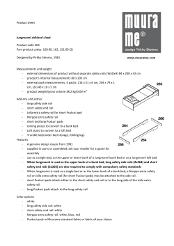


© Copyright 2026