
FUSION HIGH-PERFORMANCE MULTI-BAND LTE ROUTER ™
FUSION™
HIGH-PERFORMANCE MULTI-BAND LTE ROUTER
User Manual
Fusion™ High-Performance Multi-Band LTE Router
PN 001-0000-602 Rev. D
Revised July 2014
REVISION HISTORY
REV
0
DATE
April 2012
REVISION DETAILS
Initial release. Part number 001-0000-602.
1
2
June 2012
March 2013
A
B
July 2013
November 2013
C
December 2013
D
July 2014
Updated based on user feedback.
Updated to reflect new configuration settings and functionality and added model part
numbers, carriers, MIL-STD 810, and IEC 61000-4-2 (2009).
Updated for Firmware version 1.1.7 with DeviceOutlook™.
Updated for Firmware version 1.2.0: added SMS support for shoulder tap; added
enhancements for configuring and editing IPsec tunnels; provider modes are now autoselected in Carrier Settings for WWAN connections.
Updated for Firmware version 1.2.1: added support for 5.8 GHz WiFi, which requires new
selectors in the WiFi (Access Point) » Wireless Settings tab for Band and Channel Width.
Updated for Firmware version 1.2.3: added support for HTTPS function, which enables
secure communications between Fusion and DeviceOutlook.
Copyright Notice
© 2012-2013 CalAmp. All rights reserved.
CalAmp reserves the right to modify the equipment, its specification or this manual without prior notice, in the interest
of improving performance, reliability, or servicing. At the time of publication all data is correct for the operation of the
equipment at the voltage and/or temperature referred to. Performance data indicates typical values related to the
particular product. Product updates may result in differences between the information provided in this manual and the
product shipped. For access to the most current product documentation and application notes, visit www.calamp.com.
No part of this documentation or information supplied may be divulged to any third party without the express written
consent of CalAmp. Products offered may contain software which is proprietary to CalAmp. The offer or supply of these
products and services does not include or infer any transfer of ownership.
Modem Use
The Fusion routers are designed and intended for use in fixed and mobile applications. “Fixed” assumes the device is
physically secured at one location and not easily moved to another location. Please keep the cellular antenna at a safe
distance from your head and body while the modem is in use.
Important
Maintain a distance of at least 20 cm (8 inches) between the transmitter antenna and any person while in use. This
modem is designed for use in applications that observe the 20 cm separation distance.
Interference Issues
Avoid possible radio frequency (RF) interference by following these guidelines:
• The use of cellular telephones or devices in aircraft is illegal. Use in aircraft may endanger operation and disrupt the
cellular network. Failure to observe this restriction may result in suspension or denial of cellular services to the
offender, legal action, or both.
• Do not operate in the vicinity of gasoline or diesel fuel pumps unless use has been approved or authorized.
• Do not operate in locations where medical equipment that the device could interfere with may be in use.
• Do not operate in fuel depots, chemical plants, or blasting areas unless use has been approved and authorized.
• Use care if operating in the vicinity of protected personal medical devices, i.e., hearing aids and pacemakers.
• Operation in the presence of other electronic equipment may cause interference if equipment is incorrectly
protected. Follow recommendations for installation from equipment manufacturers.
Mobile Application Safety
• Do not change parameters or perform other maintenance of the Fusion while driving.
• Road safety is crucial. Observe National Regulations for cellular telephones and devices in vehicles.
• Avoid potential interference with vehicle electronics by correctly installing the Fusion. Leveraging the FCC Modular
approval of the Cellular and WiFi module requires professional installation to avoid antenna correlation.
UL Listed models only
When operating at elevated temperature extremes, the surface may exceed +70 Celsius. For user safety, the
Fusion should be installed in a restricted access location.
WARNING — EXPLOSION HAZARD, do not connect while circuit is live unless area is known to be nonhazardous.
For more information see APPENDIX C — UL Installation Instructions and Non-Incendive Field Wiring.
Fusion Multi-Network LTE Router PN 001-0000-602 Rev. C | Page i
TABLE OF CONTENTS
1 Product Overview ........................................................................................................................... 1
1.1
Module Identification ............................................................................................................................................ 1
1.2
Features and Benefits of the Fusion Multi-Network LTE Router ........................................................................... 2
1.3
General Specifications ............................................................................................................................................ 2
1.4
Mechanical Specifications ...................................................................................................................................... 4
1.5
Order Information .................................................................................................................................................. 5
1.5.1
Accessories ................................................................................................................................................... 5
1.6
External Connectors ............................................................................................................................................... 6
1.7
LEDs ........................................................................................................................................................................ 8
1.7.1
1.8
Normal Power-Up Sequence ........................................................................................................................ 9
Antenna.................................................................................................................................................................. 9
2 Getting Started.............................................................................................................................. 10
2.1
Package Contents ................................................................................................................................................. 10
2.2
Power Supply Connection .................................................................................................................................... 10
2.3
Device Connections .............................................................................................................................................. 10
2.4
LAN Configuration ................................................................................................................................................ 11
2.5
Log In .................................................................................................................................................................... 12
2.6
LTE Connection .................................................................................................................................................... 13
3 Fusion Web Interface .................................................................................................................... 15
3.1
Unit Status............................................................................................................................................................ 15
3.2
General Settings ................................................................................................................................................... 17
3.2.1
3.2.2
3.2.3
3.3
Unit ID ......................................................................................................................................................... 17
Unit Password ............................................................................................................................................. 18
Dynamic DNS .............................................................................................................................................. 18
ETH0, ETH1, ETH2 (Ethernet 0, 1, and 2) ............................................................................................................. 20
3.3.1
3.3.2
3.3.3
3.3.4
Status .......................................................................................................................................................... 20
IP Settings ................................................................................................................................................... 22
Connection Manager .................................................................................................................................. 24
Statistics ...................................................................................................................................................... 26
3.4
GeminiG3 (ETH2) .................................................................................................................................................. 27
3.5
WiFi (Access Point) ............................................................................................................................................... 28
3.5.1
3.5.2
3.5.3
3.5.4
Status .......................................................................................................................................................... 28
Wireless Settings......................................................................................................................................... 30
IP Settings ................................................................................................................................................... 32
Statistics ...................................................................................................................................................... 33
Fusion Multi-Network LTE Router PN 001-0000-602 Rev. C | Page ii
3.6
WiFi (Client).......................................................................................................................................................... 34
3.6.1
3.6.2
3.6.3
3.6.4
3.6.5
3.6.6
3.7
WWAN0 / WWAN1 .............................................................................................................................................. 42
3.7.1
3.7.2
3.7.3
3.7.4
3.7.5
3.8
Status .......................................................................................................................................................... 42
Carrier Settings ........................................................................................................................................... 45
IP Settings ................................................................................................................................................... 46
Connection Manager .................................................................................................................................. 48
Statistics ...................................................................................................................................................... 49
Serial .................................................................................................................................................................... 50
3.8.1
3.8.2
3.8.3
3.8.4
3.9
Status .......................................................................................................................................................... 34
Wireless Settings......................................................................................................................................... 36
IP Settings ................................................................................................................................................... 38
Site Survey .................................................................................................................................................. 39
Connection Manager .................................................................................................................................. 39
Statistics ...................................................................................................................................................... 41
Status .......................................................................................................................................................... 50
Serial Settings ............................................................................................................................................. 51
IP Settings ................................................................................................................................................... 53
Statistics ...................................................................................................................................................... 54
Router Settings..................................................................................................................................................... 54
3.9.1
3.9.2
3.9.3
3.9.4
3.9.5
3.9.6
3.9.7
Interface Priority ......................................................................................................................................... 54
Application Routing .................................................................................................................................... 55
Port Forwarding .......................................................................................................................................... 56
MAC Filtering .............................................................................................................................................. 58
IP Filtering ................................................................................................................................................... 59
Static Routing .............................................................................................................................................. 62
Routing Table .............................................................................................................................................. 63
3.10 Security ................................................................................................................................................................ 64
3.10.1
3.10.2
3.10.3
3.10.4
IPsec ............................................................................................................................................................ 64
HTTPS .......................................................................................................................................................... 67
RADIUS ........................................................................................................................................................ 68
Security Policy ............................................................................................................................................. 69
3.11 Monitor & Control................................................................................................................................................ 70
3.11.1
3.11.2
3.11.3
3.11.4
3.11.5
3.11.6
3.11.7
Status .......................................................................................................................................................... 70
SMS ............................................................................................................................................................. 71
SNMP .......................................................................................................................................................... 72
NMEA .......................................................................................................................................................... 74
Power Management ................................................................................................................................... 74
Monitoring .................................................................................................................................................. 75
I/O Control .................................................................................................................................................. 77
3.12 GPS ....................................................................................................................................................................... 78
3.12.1
3.12.2
Status .......................................................................................................................................................... 78
AAVL Settings .............................................................................................................................................. 80
Fusion Multi-Network LTE Router PN 001-0000-602 Rev. C | Page iii
3.13 Maintenance ........................................................................................................................................................ 83
3.13.1
3.13.2
3.13.3
3.13.4
3.13.5
3.13.6
3.13.7
3.13.8
Status .......................................................................................................................................................... 83
Firmware ..................................................................................................................................................... 84
WWAN Firmware ........................................................................................................................................ 85
Hardware .................................................................................................................................................... 86
Unit Configuration ...................................................................................................................................... 87
DeviceOutlook™ .......................................................................................................................................... 88
System Log .................................................................................................................................................. 90
USB Log ....................................................................................................................................................... 91
APPENDIX A — Abbreviations and Definitions ................................................................................... 92
APPENDIX B — Mechanical Specifications.......................................................................................... 94
APPENDIX C — UL Installation Instructions and Non-Incendive Field Wiring .................................... 99
APPENDIX D — Firmware Upgrades ................................................................................................. 101
Procedure for upgrading Fusion router firmware......................................................................................................... 103
Procedure for upgrading cell module firmware in the Fusion router ........................................................................... 104
APPENDIX E — WiFi Concurrent Configuration as Access Point and Client ..................................... 108
WiFi Concurrent Mode.................................................................................................................................................. 108
WiFi Nonconcurrent Mode – Client Mode .................................................................................................................... 109
WiFi Nonconcurrent Mode – Access Point Mode ......................................................................................................... 110
APPENDIX F —Using IPsec to Create IP Persistence ......................................................................... 111
1. The Problem With Multiple WANs ............................................................................................................................ 111
2. IPsec Tunnel............................................................................................................................................................... 112
3. Advantages of Using IPsec ......................................................................................................................................... 115
APPENDIX G — Service And Support And Warranty Statement....................................................... 116
Warranty Statement ..................................................................................................................................................... 117
Fusion Multi-Network LTE Router PN 001-0000-602 Rev. C | Page iv
1
PRODUCT OVERVIEW
Fusion offers a single, flexible platform to address a variety of wireless communications needs with over-the-air
configuration and system monitoring for optimal connectivity. This ready-to-deploy broadband router enables wireless
data connectivity over public and private LTE cellular networks at 4G speeds.
For the ultimate in versatility, the Fusion provides high-speed 4G LTE public safety band 14 broadband connectivity for
private infrastructure as well as 700 MHz Band 13 or 17 and 1700/2100 MHz AWS Band 4 (with 3G EV-DO/HSPA
fallback modes) based on 3GPP Standard E-UTRA Release 8 technologies. Three Ethernet ports support LAN
configurations that provide for the unique requirements of third-party VPN middleware providers.
An optional 802.11 b/g/n WiFi interface access point and client operations supports connectivity to IP applications in a
variety of different connection scenarios. Dual USB 2.0 host interfaces are provided to support Serial IP communication
(using the supported USB to RS-232 Converter cable accessory) and writing event log files to a USB flash drive.
Anticipated future uses include connection of other optional USB peripherals such as ZigBee or Bluetooth adapters.
The Fusion includes an easy to use web-based management and configuration interface, and comprehensive remote
management facilities are available. Cellular/WiFi/Ethernet rule-based and application port-based switching enables IP
control such as segregating traffic specific to designated bearer networks and choosing the WAN fallback order. The
Fusion aggregates WANs, including CalAmp’s narrowband technology, making it a powerful and unique enabler of
interoperable network technologies.
The Fusion includes an IP router that facilitates traffic routing between all of the concurrently operating networks. The
integrated router simplifies installation cabling requirements by requiring only a single cable connection with onboard
computing equipment, and offloading routing processor burdens and setup complexities. The Fusion fully integrates
with CalAmp Gemini narrowband equipment to extend their functionality to include LTE connectivity and access
additional Fusion peripherals.
1.1
MODULE IDENTIFICATION
The module identification label can be found on the bottom of your Fusion device. This label contains the product part
number, the serial number, FCC and IC IDs as well as carrier specific information that will be required when activating
your data account. The following is a sample portrayal of the identification label; identifiers and their placement will
vary depending on model and installed options, and actual bar-coded numbers on each unit will differ.
Figure 1 Fusion identification label example
Fusion Multi-Network LTE Router PN 001-0000-602 Rev. C | Page 1
1.2
FEATURES AND BENEFITS OF THE FUSION MULTI-NETWORK LTE ROUTER
• Band 13, 17 or 4 LTE for public infrastructure
• Support for Band 12 or 14 LTE or where permitted (Band 14 pending FCC certification) for private or commercial
infrastructure
• Supports dual cell modules for mixing public and private bands or multiple carriers
• Superior RF performance with MIMO capabilities
• Secure IPsec VPN connectivity, HTTPS, and RADIUS
• Autonomous WAAS enabled GPS with local and host reporting
• Supports Dynamic or Static WAN IP
• Inbound and Outbound Ethernet Routing
• DHCP Server and Inbound port mapping/translation (Port Forwarding)
• Firewall configuration for increased network security
• Diversity antenna port/auxiliary port for increased receive sensitivity for dual cell module
• Local or remote configuration using HTML web server
• Inbound IP termination with Static IP
• Persistent Domain Names with Dynamic DNS
• Ethernet and WiFi ports support LAN and WAN operation
• Dual SIM card slot, support multiple carrier contracts
• USB and digital/analog I/O for external devices
• Housed in a rugged metal chassis, Fusion meets MIL-STD-810F certification (for dry heat and cold storage and
operation, cold start, humidity, random vibration, and mechanical shock) and IEC 61000-4-2 (2009) for electrostatic
discharges
• CalAmp DeviceOutlook remote management service, built on the solid, proven performance of the COLT (CalAmp
On-Line Telemetry) platform and CalAmp Enterprise Services (CES)
1.3
GENERAL SPECIFICATIONS
Product specifications are subject to change without notice.
General
Input Voltage
10 to 30 VDC
Power Consumption
Single Cellular Module and GPS
Rx: 5.5W (no WiFi); 7.7W with WiFi
Tx: 9.1W (no WiFi); 13.0W with WiFi
DL MIMO, UL SISO
LTE Diversity Support
Security
Carrier Approvals
Dual Cellular Modules and GPS
Rx: 5.8W (no WiFi); 10W with WiFi
Tx: 14W (no WiFi); 16.9W with WiFi
3GPP Rel 8 security sublayer, IPsec IKEv1 and IKEv2 VPN tunnel termination, HTTPS,
and RADIUS
Verizon Wireless, VTEL, PTCRB certified for AT&T
Certifications
FCC Part 15 Subpart B Class A, IC ICES-003
MIL-STD 810F (dry heat and cold storage and operation, cold start, humidity, random
vibration, and mechanical shock), IEC 61000-4-2 (2009) electrostatic discharges
Connectors/Interface
Antenna connectors and LED indicators vary with device model (installed options)
Device Management
SNMP, embedded HTTP server for setup and help, DeviceOutlook
Fusion Multi-Network LTE Router PN 001-0000-602 Rev. C | Page 2
LED Indicators
Power
POWER, STATUS, ETH0, ETH1, ETH2, GPS, WWAN0, WWAN1 (with dual radio option),
WiFi (when equipped with WiFi option)
4-pin locking, ignition sense and alarm inputs
Console/Setup
3-wire serial connection in USB Mini-B form factor
Ethernet
(3) 10/100 Mbps RJ-45, auto MDIX, Auto-negotiation
USB
(2) Type A female
I/O
2 digital I/O, 2 analog inputs,
2 outputs (relay driven contact closures)
(3) SMA-RP (802.11 b/g/n WiFi, optional)
(2) SMA (cellular) WWAN0 (single or dual radio)
(2) SMA (cellular) WWAN1 (dual radio option only)
(1) SMA (GPS)
Antenna
Mechanical/Environmental
Dimensions
1.9 in. (4,8 cm) height × 6.0 in (15,3 cm) width × 5.5 in. (14 cm) depth
Weight
2.5 lb. (1,13 kg)
Temperature Range
-22° to +158° F (-30° to +70° C)
Humidity
5% to 95% non-condensing
LTE Technology/Bands
Supported bands vary with device model.
Band 14
700 MHz “D” Block DL MIMO, UL SISO
Band 13
700 MHz DL MIMO, UL SISO
Band 17
700 MHz DL MIMO, UL SISO
Band 4
1700/2100 MHz AWS DL MIMO, UL SISO
CDMA Technology/Bands
Supported bands vary with device model.
EVDO Rev A (IS-856-A)
800 MHz Cellular/1900 MHz PCS
Downlink 3.1 Mbps; Uplink 1.8 Mbps
800 MHz Cellular/1900 MHz PCS
Downlink 2.4 Mbps; Uplink 153.6 kbps
800 MHz Cellular/1900 MHz PCS
Downlink 153.6 kbps; Uplink 153.6 kbps
1xEVDO Rev 0 (IS-856)
1xRTT (IS-2000)
GSM Technology/Bands
Supported bands vary with device model.
UMTS/HSPA
850/900, 1800/1900, 2100 MHz
Downlink 7.2 Mbps, Uplink 2.0 Mbps
Quad-band 850/900, 1800/1900 MHz
Downlink 236 kbps, Uplink 236 kbps
EDGE/GPRS
WiFi Technology/Bands
IEEE 802.11 b/g/n
32 bit mPCI type lllA high power/performance WiFi
Security
WPA-PSK (TKIP encryption), WPA2-PSK (CCMP encryption), 64-bit/128 bit WEP
encryption, WPA Enterprise and WPA2-Enterprise
802.11b: up to 11Mbps
802.11g: up to 54Mbps
802.11n: up to 144Mbps
Data Rates
Fusion Multi-Network LTE Router PN 001-0000-602 Rev. C | Page 3
1.4
MECHANICAL SPECIFICATIONS
The following table and figure show overall dimensions of the chassis of the Fusion Multi-Network LTE Router.
Dimensioned drawings of the chassis with mounting options (bracket, mounting plate, or DIN rail mount) are provided
in APPENDIX B. The drawings and associated data may be used for layout reference, but it is advised that a physical
comparison be made to the unit and bracket before laying out and drilling any holes.
Table 1 Fusion chassis overall dimensions
Dimension
Inches
Centimeters
Height
1.90
4,83
Width
6.00
15,2
5.50
14,0
5.28
13,4
Depth
(Overall)
Depth
(Chassis only)
Figure 3 Side tapped mounting hole location detail — typical
both sides.
Figure 2 Fusion router Mechanical Drawing
Figure 4 Tapped mounting hole location detail — top only.
#8-32 UNC – 2B thread × 0.30 in. (0,76 cm) depth
2 holes for mounting both sides (4 holes total).
#6-32 UNC – 2B thread × 0.12 in. (0,30 cm) depth
4 holes for mounting (top surface only).
Fusion Multi-Network LTE Router PN 001-0000-602 Rev. C | Page 4
1.5
ORDER INFORMATION
The following table shows the available order options and part numbers required for ordering Fusion routers.
Table 2Fusion LTE router Single Radio Band model part number information
Description
Band
Provider
Model Number
Fusion LTE Router
Fixed/Portable
GPS
Band 13
Verizon
140-9320-000
Fusion LTE Router
WiFi (3 × 3)
GPS
Band 13
Verizon
140-9320-100
Fusion LTE Router
Fixed/Portable
GPS
Band 17
AT&T
140-9340-000
Fusion LTE Router
WiFi (3 × 3)
GPS
Band 17
AT&T
140-9340-100
Fusion LTE Router
Fixed/Portable
GPS
Band 17
VTEL
190-9340-000
Fusion LTE Router
WiFi (3 × 3)
GPS
Band 17
VTEL
190-9340-100
Fusion LTE Router
Fixed/Portable
GPS
Band 12
GDB
190-930G-000
Fusion LTE Router
WiFi (3 × 3)
GPS
Band 12
GDB
190-930G-100
Table 3 Fusion LTE router Dual Radio Band model part number information
Description
Bands
Model Number
Fusion LTE Router
Fixed/Portable
GPS
Band 13 and Band 17
140-9324-000
Fusion LTE Router
WiFi (3 × 3)
GPS
Band 13 and Band 17
140-9324-100
Fusion LTE Router
Fixed/Portable
GPS
Band 12 and Band 13
190-932G-000
Fusion LTE Router
WiFi (3 × 3)
GPS
Band 12 and Band 13
190-932G-100
Fusion LTE Router
Fixed/Portable
GPS
Band 12 and Band 17
190-934G-000
Fusion LTE Router
WiFi (3 × 3)
GPS
Band 12 and Band 17
190-934G-100
1.5.1 ACCESSORIES
Table 4 Fusion Accessory Kits
Description
Comments
Part Number
Fusion Accessory Kit, Vehicle Mount Version
Vehicle mount
150-5500-013
Fusion Accessory Kit, Fixed Version
Fixed/Portable
150-5500-014
Fusion Accessory Kit, Mobile version
Mobile
150-5500-015
Table 5 Fusion Accessories
Description
Comments
Part Number
USB to RS-232 Converter cable
150-9300-010
Mobile Mount, Multiband Antenna (LTE, WiFi, GPS), Black, PCTEL
401-5099-205
Antenna, LTE LProfile HGain (Band 13/Band 17), Mag mount with
Standard antenna
401-9300-001
Fusion Multi-Network LTE Router PN 001-0000-602 Rev. C | Page 5
Description
Comments
Part Number
ground plane disc, SMA, 15 ft., 3G Fallback
Antenna, GPS, Mag Mount, SMA
401-7100-003
Antenna, WiFi, 9 in. Mag Mount, RP-SMA
401-7100-004
Category 5 100Base 7 ft. (2 m) Red Ethernet Cable
L2CAB0006
DIN Rail Mounting Plate — kit includes DIN mounting plate
assembly (with retainer spring and screw), four #6-32 × ¼-inch
length cap screws and four #6 lock washers for fastening to top
of Fusion router.
1.6
250-5800-410
EXTERNAL CONNECTORS
This section describes the external connectors for the Fusion router.
Figure 5 Front panel connections
Table 6 Front Panel connectors
Top row, from left to right:
Panel label
Connection
Description
WWAN0 M
SMA
B13/B17 LTE Rx/Tx primary antenna connector
WWAN0
SMA
B13/B17 LTE diversity connector
WWAN1 M
SMA
B14 LTE Rx/Tx primary antenna connector
WWAN1
SMA
B14 LTE diversity connector
WiFi M
RP-SMA
Primary WiFi Tx/Rx antenna connector (only populated on model with WiFi
option)
WiFi (center
connector)
RP-SMA
2× MIMO Tx/Rx antenna connector (used with 2× or 3× MIMO WiFi modules
only)
WiFi (farthest to
right)
RP-SMA
3× MIMO Tx/Rx antenna connector (used with 3× MIMO WiFi modules only)
Fusion Multi-Network LTE Router PN 001-0000-602 Rev. C | Page 6
Bottom row, from left to right:
Panel label
Connection
Description
GPS
SMA
GPS Receive antenna
Power
4-pin locking
Power, ignition sense, and alarm input
USB
USB A
2 USB Host connectors (for future use)
ETH0
RJ-45
Ethernet 10/100 Mbps
ETH1
RJ-45
Ethernet 10/100 Mbps
ETH2
RJ-45
Ethernet 10/100 Mbps
Figure 6 Rear panel connections
Table 7 Rear panel connectors
Panel label
Connection
Description
I/O
10-position
terminal socket
2 digital inputs/outputs, 2 analog inputs, 2 outputs (processor-controlled
internal relays)
Console
USB Mini-B
Mini-USB device port used for debug only
Setup
Push button
Push-button Reset / Force Factory Settings
Status
LED
Bicolor Status LED
SIM/SVC (left)
SIM card slot
Slot and tray for mini SIM card for module in WAN slot 0
WWAN0
USB Mini-B
Service port, direct connection to WWAN0 module
SIM SVC (right)
SIM card slot
Slot and tray for mini SIM card for module in WAN slot 1
WWAN1
USB Mini-B
Service port, direct connection to WWAN1 module
Fusion Multi-Network LTE Router PN 001-0000-602 Rev. C | Page 7
1.7
LEDS
Table 8 Status LEDs
Indicator
Off
Solid
Green
PWR
No power
Running
STAT
No power
Status:
Normal
GPS
Flashing
Green
Solid Amber
Flashing
Amber
Solid Red
Flashing Red
–
Hardware
power-up
sequence
Firmware
boot
sequence /
Power-down
timer
(1)
activated
Power
supply
fault
–
–
Status:
Warning
Status:
Factory
Defaults
Status:
Fault
–
Failed to
Acquire
Satellites
Acquiring
Satellites
Fault
–
–
Position Fix
Acquired
1 PPS
Activity
(2)
I/F Disabled
Connected
Rx/Tx
Activity
–
–
Fault
–
WiFi
(AP)
(2)
I/F Disabled
Ready
Rx/Tx
Activity
–
–
Fault
–
WWAN0/
WWAN1
I/F Disabled,
Idle, or
Bypassed
Connected
Rx/Tx
Activity
Fault
–
ETH
Link/Act
No link
Link OK
Activity
ETH
Speed
10 Mbps
WiFi
(Client)
–
–
Failed to
Connect
–
100 Mbps
Connecting
–
–
–
–
–
–
(1)
The “Power-Down Timer Activated” is a transient condition that exists when the “ignition” input is OFF and the
“power-management – shutdown when ignition is off” feature is activated. It means that the unit is about to shut
down and this will occur when the timer has expired.
(2)
WiFi Client has priority over the WiFi AP function. This implies that WiFi Client has ownership of the LED when it is
enabled. WiFi AP has ownership of the LED only if the WiFi Client is disabled.
Fusion Multi-Network LTE Router PN 001-0000-602 Rev. C | Page 8
1.7.1 NORMAL POWER-UP SEQUENCE
Step
Action
LED Activity
1
Apply power to the unit.
N/A
2
Internal 5-V power supply turns on.
Power LED on front panel illuminates red for
approximately 1 second.
3
Internal 1.8 V and 3.3 V power supply turn on.
Every indicator, (except Ethernet jack indicators)
illuminate amber for approximately 400 milliseconds.
4
Hardware initialization.
Every indicator turns off, except Power, which
remains amber.
5
Bootstrap program runs.
Power LED blinks amber.
6
Application starts.
Power LED illuminates solid green.
7
Application runs normally.
Power LED remains solid green. Status LED on back
panel illuminates solid green.
1.8
ANTENNA
LTE antenna connections are SMA female connectors and must be used with antenna with SMA male connectors.
When using a direct mount or rubber duck antenna, choose the antenna specific to your band requirements. Mounting
options and cable lengths are user’s choice and application specific. Each WWAN interface supports a primary and
diversity antenna connector.
Connect an active 3 - 5.5 V GPS antenna, with an average gain greater than -5 dBi, if using the GPS functionality.
Fusion routers are available with WiFi options, using RP-SMA connectors. Depending on the model, connect each WiFi
antenna to the proper connector. If equipped with a simple non-MIMO WiFi option, connect the primary WiFi antenna
to the connector labeled “M.” For Fusions equipped with MIMO WiFi (2×2 or 3×3 MIMO), connect the WiFi antennas to
any free RP-SMA connector.
This device is factory configured with default settings and is ready to be customized via the internal HTML interface
that can be accessed using a Web browser through an Ethernet connection.
Fusion Multi-Network LTE Router PN 001-0000-602 Rev. C | Page 9
2
GETTING STARTED
2.1
•
•
•
•
•
PACKAGE CONTENTS
Fusion Router
Power Cable
Mounting Bracket or Plate (depending on fixed/portable or mobile model) and hardware
Quick-Start Guide
Information Card
2.2
POWER SUPPLY CONNECTION
The Fusion router is shipped with a DC power cable used to connect the device to a DC source. The cable includes a
fuse holder. Insert the fuse in the power cable fuse holder prior to powering on the unit. The cable connections are
listed below.
Table 9 DC Power Cable Pin-out
Pin
Wire Color
Description
Notes
1
Red
VIN
DC input power lead, 13.8 V nominal (10 V to 30 V range)
2
Black
Ground
Connect to power supply ground.
3
White
Ignition Sense
Standard ignition-on signal. Maximum voltage above which ignition_sense
will be detected as ignition asserted = 9.0 V;
If IGN Sense is not used, then this line must be connected to VIN.
4
2.3
Yellow
External Alarm Input
External alarm input (active low); can be left floating in not used.
DEVICE CONNECTIONS
Important: Before you begin configuring the Fusion router, you will need an LTE contract with a carrier and an active
SIM or UICC card for each carrier / LTE module installed in the Fusion router.
1. Unscrew two screws to remove the cover plate covering the WWAN slots and insert the SIM/UICC card into the
WWAN slot(s) as shown. Insert the first SIM into the WWAN0 slot. If you are using a dual card solution, install the
second SIM/UICC card into the WWAN1 slot. (Retain the cover plate and attaching screws to reattach the cover
plate after setup is complete.)
Fusion Multi-Network LTE Router PN 001-0000-602 Rev. C | Page 10
2. Connect the cellular antennas to the appropriate SMA connectors on the front of the Fusion router as shown in the
following figure, matching the antennas for the WWAN0 module with WAN0 connectors, and antennas for the
WWAN1 with WWAN1 connectors if applicable. For each antenna pair, connect the main Rx/Tx antenna to the
connector labeled M, and MIMO/Diversity to the secondary (unmarked) connector of the pair.
3. Connect a GPS antenna to the SMA connector labeled GPS and connect WiFi antennas to the RP-SMA connectors:
one for the Main (WiFi M) and one or more (as equipped) for WiFi MIMO/Diversity (unlabeled).
4. Connect an Ethernet cable into the ETH1 port (center Ethernet connector) of the Fusion and plug the other end into
the Ethernet port of your PC.
5. Connect the Power Cable to the modem PWR port and connect to an acceptable DC power source (10-30 VDC). The
DC power cable shipped with the Fusion to connect the unit to DC power includes a fuse holder. Insert the fuse in
the power cable fuse holder before powering the unit. Cable connections are listed in the Table 9 DC Power Cable
Pin-out.
After power is applied, the Fusion Power LED will illuminate solid red for 1 second, then turn solid amber for 5-6
seconds, blink amber for 6 seconds, and then turn solid green.
2.4
LAN CONFIGURATION
The Fusion contains a DHCP server which will automatically assign an IP address to your PC, however in some cases the
user may need to change the network settings on their PC to accept the IP address from the Fusion. Before powering
on the unit, confirm that your PCs Ethernet port is set up to receive an IP address from an external DHCP server,
confirm it is not set to a static address. The process required to do this differs depending on the version of Windows
you are using.
Fusion Multi-Network LTE Router PN 001-0000-602 Rev. C | Page 11
For Windows XP users, select Start » Control Panel » Network Connections. Right click Local Area Connection and
select Properties to open the configuration dialog box for Local Area Connection. Select Internet Protocol (TCP/IP) and
click Properties to open the TCP/IP configuration window. On the General tab, select Obtain an IP address
automatically and Obtain DNS server address automatically. Click OK to complete TCP/IP configuration.
Figure 7 LAN Configuration Settings in Windows XP
2.5
LOG IN
Start your Web browser and enter 192.168.1.50 in the address bar. A Web Server Authentication window appears.
Note: The Ethernet cable between the Fusion and your PC must be connected to ETH1 for this IP address to work.
Fusion Multi-Network LTE Router PN 001-0000-602 Rev. C | Page 12
Figure 8 Web Server Authentication window
Enter the User Name: admin and the Password: password and click OK to log into the modem Home Page. Information
about the Unit Status is displayed on the Home Page.
2.6
LTE CONNECTION
Note: Before you begin configuring the Fusion router, you will need an LTE account and an active SIM or UICC card for
each carrier / LTE module installed in the Fusion router.
The Fusion Web interface is divided in two sections. In the left pane is the main navigation menu. On the right is the
content area for the selected page. Initially, information about the Unit Status is displayed.
From the main navigation menu on the left, select WWAN0 to navigate to the WWAN0 page. The Status tab for
WWAN0 is displayed. Select the Carrier Settings tab.
Figure 9 Enable WWAN0 Interface and use Provider #1 for LTE connection
If the interface is not already enabled, in the Configuration section click Enabled and in the same section, click Save to
enable the WWAN0 interface.
Fusion Multi-Network LTE Router PN 001-0000-602 Rev. C | Page 13
In the Provider #1 section, if Provider #1 is not already enabled click Enabled and in the same section, click Save to
enable Provider #1.
Leave APN, User, and Password blank unless you have received specific values from your carrier. For most cases,
Authentication should remain set as Any.
It may take several minutes to establish the connection after it has been enabled for the first time. Verify the
connection is active by clicking the Status tab. See the following figure.
Figure 10 WWAN0 Status tab showing LTE Link connected
Fusion Multi-Network LTE Router PN 001-0000-602 Rev. C | Page 14
3
FUSION WEB INTERFACE
The Fusion Web interface is divided into two sections. In the left pane is the main navigation menu. On the right is the
content area for each page.
Figure 11 CalAmp Fusion High Performance Multi-Band Router Web interface displaying Unit Status page
Note: If the computer you are using has previously been used to set up a CalAmp router, you may need to delete the
browser history (specifically, temporary Internet files) for some pages of the web interface to display correctly.
The navigation menu for your Fusion may contain fewer sections than shown here depending on which options are
installed in your unit.
3.1
UNIT STATUS
The Unit Status is the first page displayed when navigating to the Fusion Web interface and is the home page. Select
Unit Status from the main navigation menu (or click Home) to return to this page. From this page you can view unit
identification, system status, and Interface information.
Fusion Multi-Network LTE Router PN 001-0000-602 Rev. C | Page 15
Figure 12 Fusion Web interface Unit Status page
System Information
• Unit ID
User-defined name given to the unit for ease of reference and used by various services.
• Local Time
Displays the current date and time (UTC) as received from the GPS receiver.
• System Up time
Displays the duration the system has been up in hours, minutes, and seconds.
• Software Version
Displays the current system firmware version loaded. Please visit www.calamp.com for the latest updates.
• Default Route
Displays the name of the WAN interface used as the default route. This value can change dynamically, based on the
available WANs and WAN failover rules specified.
Interface Information
• Interface
Name of the interface.
• State
Displays the current state of the interface. Possible states are listed in the following table.
• IP Address and Subnet Mask
Displays the IP address and subnet mask of the interface.
Important concept: Note that the Fusion acts as a router between each of its interfaces, ETH0, ETH1, ETH2, WiFi,
WWAN0, and WWAN1 (when installed and active), not as a switch or hub. Each of these interfaces, when enabled,
Fusion Multi-Network LTE Router PN 001-0000-602 Rev. C | Page 16
must have a unique IP address that (with the subnet mask) specifies a subnet that is separate (non-overlapping)
from subnets specified for any of the other Fusion interfaces.
Table 10 Possible states of Fusion interfaces
ETH (LAN)
ETH (WAN)
WiFi AP
WiFi Client
WWAN
Serial
Unknown
Unknown
Unknown
Unknown
Unknown
Unknown
Disabled
Disabled
Disabled
Disabled
Disabled
Down
Inactive
Inactive
Inactive
Inactive
Disconnected
Disabled
No Cable
No Cable
Configuring IP
Scanning
Connecting
Listening
Configuring IP
Acquiring IP
Connecting
Acquiring IP
Connected
No Cable
Connecting
Connecting
Connected
Connecting
Connecting
Connected
Connected
Connected
Connected
• IP Address
Displays the IP address assigned to this interface.
• Subnet Mask
Displays the subnet mask of this interface
• MAC Address
Media Access Control Address; every interface (i.e. LAN or WAN) has a unique hardware serial number or MAC
address to identify each Network Device from all others. Note that the optional WiFi client and Access Point
interfaces are provided by the same hardware module and therefore share the same MAC address.
3.2
GENERAL SETTINGS
The General Settings page allows customization of basic settings of the Fusion. Select General Settings from the main
navigation menu to navigate to the General Settings page. The General Settings page contains three tabs: Unit ID, Unit
Password, and Dynamic DNS.
3.2.1 UNIT ID
Figure 13 General Settings – Unit ID
• ID
This identifier serves to distinguish this unit from other units in the network. This identification number is also the
TAIP identification used for GPS reporting and serves as the ‘syslocation’ for the SNMP facility.
Fusion Multi-Network LTE Router PN 001-0000-602 Rev. C | Page 17
3.2.2 UNIT PASSWORD
Figure 14 General Settings – Unit Password
• Current Unit Password
The current unit password must be provided here to enable changing the unit password.
• New Unit Password
Enter new password here.
• Confirm New Unit Password
Re-enter the new password.
This password controls access to the Fusion HTML web interface via a local Ethernet connection and via Remote login.
(See the Security section.) Some functions such as SNMP will require an additional password.
3.2.3 DYNAMIC DNS
Figure 15 General Settings – Dynamic DNS
Fusion Multi-Network LTE Router PN 001-0000-602 Rev. C | Page 18
Dynamic DNS is a system that allows the domain name data of a computer with a varying (dynamic) IP addresses held
in a name server to be updated in real time in order to make it possible to establish connections to that machine
without the need to track the actual IP addresses at all times. A number of providers offer Dynamic DNS services
(DDNS), free or for a charge.
Fusion allows publishing a distinct IP address or mnemonic name association for each of its WAN interfaces, as well as
for the WAN interface used as the default route. Example: car54 (for the default route), car54_wifi, car54_LTEB14,
car54_VZW.
Configuration
• Dynamic DNS
Selecting Enabled will allow the Fusion to provide the selected service dynamic IP address information. Selecting
Disabled will stop any IP information from being sent to the selected service.
• Client
Select the Dynamic DNS client to use. No-IP is the default DNS service.
Server Settings
• Server Address
The internet address to communicate the Dynamic DNS information to. Default is dynupdate.no-ip.com.
• User Name
The user name used when setting up the account. Used to login to the Dynamic DNS service.
• Password
The password associated with the account.
• Update Interval
Sets the interval, in minutes (0 to 65,535), the modem will update the Dynamic DNS server of its carrier assigned IP
address. Each update is considered a data call by the cellular provider and could deplete low usage data plan
minutes. Setting the duration too long could lead to periods of lost connectivity when the device IP address
changes.
Client Settings
• Enable
The IP address updates will only be supplied to the service if this radio button is set.
• Host Configuration
The unique device name to register with the DDNS service.
• WAN Interface
The WAN interface whose IP address will be published for this DDNS registration.
The Clear button on each entry can be used to remove that particular DDNS configuration.
You must click Save for changes to take effect.
Fusion Multi-Network LTE Router PN 001-0000-602 Rev. C | Page 19
3.3
ETH0, ETH1, ETH2 (ETHERNET 0, 1, AND 2)
The same instructions apply to settings for all Ethernet interfaces. (Except if the Fusion is equipped with the GeminiG3
narrowband WAN option. If this is the case, see 3.4 GeminiG3 (ETH2)). Each Ethernet interface can be configured as a
LAN or a generic WAN. Select the interface, ETH0, ETH1, or ETH2, as applicable, from the main navigation menu to
navigate to the page for the interface.
Note: When assigning IP addresses, each interface, ETH0, ETH1, and ETH2 (and WiFi, WWAN0, and WWAN1, when
active) must have a unique IP address that (with the subnet mask) specifies it is on a subnet that is separate (nonoverlapping) from subnets specified for any of the other Fusion interfaces.
3.3.1 STATUS
ETH configured as a LAN
Figure 16 ETH0 / ETH1 / ETH2 – Status (configured as LAN)
ETH configured as a WAN
Figure 17 ETH0 / ETH1 / ETH2 – Status (configured as WAN)
Fusion Multi-Network LTE Router PN 001-0000-602 Rev. C | Page 20
Status
• Interface Status
See Table 10 Possible states of Fusion interfaces in Unit Status.
• Interface Up Time
Number of days, hours, minutes, and seconds that the interface has been up (connected state).
IP
• IP Address
IP address assigned to this interface.
Note: When assigning IP addresses, each interface, ETH0, ETH1, and ETH2 (and WiFi, WWAN0, and WWAN1, when
active) must have a unique IP address that (with the subnet mask) specifies it is on a subnet that is separate (nonoverlapping) from subnets specified for any of the other Fusion interfaces.
• Subnet Mask
The subnet mask assigned to this interface.
• MTU
The Maximum Transmit Unit size. Should be left as the default value of 1500 bytes in most cases.
Note: The following only apply when the interface is configured as a WAN.
• Gateway
IP address of the WAN gateway. This is used for routing packets to remote networks.
• DNS Server 1, DNS Server 2
IP address of the (1) preferred and (2) alternate DNS server.
• Lease Time
If the interface is set up to request an IP address from a DHCP server, this is the lease duration.
• Lease Expires in
If the interface is set up to request an IP address from a DHCP server, this is the time remaining in the current lease.
Link
• Cable Status
Connected or disconnected.
Fusion Multi-Network LTE Router PN 001-0000-602 Rev. C | Page 21
3.3.2 IP SETTINGS
ETH configured as a LAN
Figure 18 ETH0 / ETH1 / ETH2 – IP Settings (configured as LAN)
Fusion Multi-Network LTE Router PN 001-0000-602 Rev. C | Page 22
ETH configured as a WAN
Figure 19 ETH0 / ETH1 / ETH2 – IP Settings (configured as WAN)
Modes of Operation
• Type
Select LAN if this Ethernet port is connecting to a local area network. Select WAN if the Fusion is connecting to a
wide area network through an external router or gateway.
IP Configuration
• IP Address/Subnet Mask
Sets the IP Address and Subnet Mask for the Ethernet interface.
Note: When assigning IP addresses, each interface, ETH0, ETH1, and ETH2, (and WiFi, WWAN0, and WWAN1, when
active) must have a unique IP address that (with the subnet mask) specifies it is on a subnet that is separate (nonoverlapping) from subnets specified for any of the other Fusion interfaces.
• MTU
Maximum Transmission Unit, maximum packet size allowed to be transmitted. Should be left as default value of
1500 in most cases.
Fusion Multi-Network LTE Router PN 001-0000-602 Rev. C | Page 23
DHCP Server Configuration
• DHCP Server
When enabled, the DHCP server will assign an IP addresses to each device connected to the Ethernet port. IP
addresses assigned will be in the defined range (see below) and on the same subnet as the Fusion.
• Dynamic Leases (Start IP Address/End IP Address)
External LAN devices connected to the Fusion will be assigned IP address in this range when DHCP is enabled. This
range of IP addresses must be on the same subnet as Fusion (the range must be compatible with the IP address and
network mask set for the Ethernet interface).
IP Configuration
• Mode
Select Dynamic or Static. If you select Dynamic, the rest of the entries on this page will be shaded out.
• IP Address
Static address for this interface. It must be on the same subnet as the gateway.
• Subnet Mask
Will be assigned by the gateway.
• Gateway
IP address of the Gateway (DHCP host). If not known this can be left as all zeros.
• DNS Server 1, DNS Server 2
IP address of the DNS server for this unit. If not known, this can be left as all zeros.
NAT Configuration
• NAT
Enable or Disable NAT (Network Address Translation)
3.3.3 CONNECTION MANAGER
The Connection Manager tab allows you to configure the Fusion router to set criteria that determine whether a reliable
connection exists or the link is down. This feature can also be used to only generate pings on an interface if no traffic is
sent via this interface. This can be useful to maintain an active connection. Connection Manager features are available
when the interface is configured for WAN mode only and are not applicable or available when the interface is
configured for LAN.
Fusion Multi-Network LTE Router PN 001-0000-602 Rev. C | Page 24
ETH Configured as a LAN
Figure 20 ETH0 / ETH1 / ETH2 – Connection Manager (configured as LAN)
When an Ethernet interface (ETH0, ETH1, or ETH2) is configured as a LAN, settings the Connection Manager are not
applicable, so none of the configuration settings are available. Connection Manager settings are only applicable for an
Ethernet interface if it is configured as a WAN.
ETH Configured as a WAN
Figure 21 ETH0 / ETH1 / ETH2 – Connection Manager (configured as WAN)
When an Ethernet interface (ETH0, ETH1, or ETH2) is configured as a WAN, settings the Connection Manager are
applicable, and so the configuration settings shown in the figure above are available.
Fusion Multi-Network LTE Router PN 001-0000-602 Rev. C | Page 25
Active Disconnection Probe
• Enable
Check this box to detect link connection status based on pings to a specified IP address or the WAN’s Gateway.
• Ping Interval
Interval in seconds between each ping if no packets have been received.
• Ping this WAN’s Gateway
To ping the WAN’s Gateway rather than a specific IP address, check this box.
• Ping this IP Address
Enter the IP address that pings will be sent to, to detect the link state. Enter the IP address of a known external
reachable server or network (for example, 8.8.8.8).
• Force link down
Specify the number of pings, if which are unsuccessful, the link will be declared down. If disabled, the interface will
never be forced down if pings fail.
Received Packet Disconnection Probe
• Enable
Check this box to enable link detection based on whether packets are received.
• Force link down after
Enter the number of seconds after which, if no packets have been received, the link will be declared down.
3.3.4 STATISTICS
Figure 22 ETH0 / ETH1 / ETH2 – Statistics
The statistics page lists the total number of packets and bytes transmitted and received since the time the units status
was listed as connected. These numbers reset to 0 when the Ethernet interface disconnects.
Fusion Multi-Network LTE Router PN 001-0000-602 Rev. C | Page 26
3.4
GEMINIG3 (ETH2)
This menu selection replaces the ETH2 LAN setting and appears in the main navigation pane when the Fusion is
equipped with the GeminiG3 narrowband WAN option.
When equipped, this option transforms the ETH2 LAN into a Narrowband WWAN interface by customizing the ETH2
configuration page to the CalAmp Gemini product line.
Refer to CalAmp part number 001-0001-401, Gemini G3 ADB User Manual for details on the GeminiG3 configuration.
Figure 23 GeminiG3 (ETH2) – Status
The Gateway and Subnet mask will be assigned by the GeminiG3 in this configuration.
• RF Gateway MAC
The Paragon 4 RF MAC address.
• RF Gateway IP
The Paragon 4 RF IP address.
• Local Status
Status of the local connection between the Fusion and GeminiG3.
• RF Status
GeminiG3 and Paragon4 connection RF status.
• RSSI
GeminiG3 Receive Signal Strength Indicator in dBm.
Fusion Multi-Network LTE Router PN 001-0000-602 Rev. C | Page 27
• Channel
GeminiG3 RF Channel used to communicate with the Paragon4.
• IP Address
GeminiG3 RF IP address.
• Subnet Mask
GeminiG3 RF subnet mask.
3.5
WIFI (ACCESS POINT)
Select WiFi (Access Point) from the main navigation menu to navigate to the WiFi (Access Point) page, which contains
tabs for status and configuration of the WiFi Access Point interface.
Note: Until Release 1.1.7 of the Fusion firmware, the Fusion could only be set to function as either a WiFi Client or a
WiFi Access Point, but not both simultaneously. Fusion firmware version 1.1.7 added the capability to configure the
Fusion as both a WiFi Client and WiFi Access Point simultaneously. However, since both the Access Point and the Client
use the same radio, once the radio channel is set for the Access Point, the Client must use the same channel. The client
will only look for external Access Points with the same WiFi radio channel that is selected for its own internal Access
Point. The client will not scan for Access Points using any other channels. For more information about using the Fusion
WiFi interface in concurrent or non-concurrent modes, see APPENDIX E— WiFi Concurrent Configuration as Access
Point and Client.
3.5.1 STATUS
Figure 24 WiFi (Access Point) – Status
Status
• Interface Status
See Table 10 Possible states of Fusion interfaces in Unit Status.
• Interface Up Time
Number of days, hours, minutes, and seconds that the interface has been up (connected state).
Fusion Multi-Network LTE Router PN 001-0000-602 Rev. C | Page 28
IP
• IP Address
IP address assigned to this interface.
• Subnet Mask
The subnet mask assigned to this interface.
Link
• WiFi Status
When status is listed as N/A, the interface is disabled; When status is listed as Ready: Interface is ready to accept
clients.
Fusion Multi-Network LTE Router PN 001-0000-602 Rev. C | Page 29
3.5.2 WIRELESS SETTINGS
Figure 25 WiFi (Access Point) – Wireless Settings
Configuration
• Interface
Selecting Enabled will enable the Wireless interface. Selecting Disabled will disable it.
Wireless Configuration
• SSID
The SSID is the name of the wireless local network. Devices connecting to the Fusion WiFi access will identify the
Access Point by this SSID.
Fusion Multi-Network LTE Router PN 001-0000-602 Rev. C | Page 30
• Band
Select the radio-frequency band for WiFi: 2 GHz or 5 GHz. (802.11 b and g operate in the 2 GHz band; 802.11 n may
operate in 2 GHz or 5 GHz.) The default setting is 2 GHz.
• Channel Width
Select the width of the WiFi channel. 20 MHz will limit the channel to 20 MHz wide; 20/40 MHz will enable the use
of a 40 MHz wide channel when available.
• Channel
Select the WiFi channel the module will transmit on. If there are other WiFi devices in the area the Fusion should be
set to a different channel than the other access points. Channels available for selection depend on the selected
Band.
Note: If you are configuring the Fusion WiFi interface as both a client and an Access Point, because both use the
same WiFi radio, the client will be restricted to the channel you select and therefore will only connect to other
Access Points that use this channel, and will not scan for Access Points using any other channels.
• 802.11 Mode
Select the WIFi 802.11 mode: B, G, or N. Available selections depend on selected Band.
• Authentication
Select authentication method. Options are Shared; WPA-PSK, WPA2-PSK, WPA-Enterprise and WPA2-Enterprise.
WPA2-PSK or WPA2-Enterprise is recommended if security is required.
• Encryption
Select the encryption method. Options are None, WEP, TKIP, or CCMP. Because these options depend on the
authentication method selected, some options will not be available.
• WEP Key Length
Available only if the WEP option is selected for encryption. Choose 64 or 128 bit key.
• WEP Key Type
Available only if the WEP option is selected for encryption.
• WEP Key Index
Available only if the WEP option is selected for encryption. Enter the encryption key.
RADIUS Configuration Server #1, Server #2
• IP
The IP address of the RADIUS server.
• Port
The port number of the server.
• Secret
Sets the shared Secret to use with the server.
• Confirm Secret
Re-type the server shared Secret to confirm.
Fusion Multi-Network LTE Router PN 001-0000-602 Rev. C | Page 31
3.5.3 IP SETTINGS
Figure 26 WiFi (Access Point) – IP Settings
IP Configuration
• IP Address/Subnet Mask
Sets the IP Address and Subnet Mask for the WiFi interface.
Note: When assigning IP addresses, each interface, ETH0, ETH1, ETH2,and WiFi (and WWAN0 and WWAN1, when
active) must have a unique IP address that (with the subnet mask) specifies it is on a subnet that is separate (nonoverlapping) from subnets specified for any of the other Fusion interfaces.
• MTU
Maximum Transmission Unit, maximum packet size allowed to be transmitted. Should be left as default value of
1500 in most cases.
Fusion Multi-Network LTE Router PN 001-0000-602 Rev. C | Page 32
DHCP Server
• DHCP Server
When enabled, the DHCP server will assign an IP addresses to each device connected to the Ethernet port. IP
addresses assigned will be in the defined range (see below) and on the same subnet as the Fusion.
• Dynamic Leases (Start IP Address/End IP Address)
External LAN devices connected to the Fusion will be assigned IP address in this range when DHCP is enabled. This
range of IP addresses must be on the same subnet as Fusion (the range must be compatible with the IP address and
network mask set for the WiFi interface).
• Static Leases
Allows you to assign and lease IP addresses to devices on your network, based on the specific MAC address of each.
Other
• Lease Duration
Length of time in seconds that leases will last for IP addresses assigned.
• Domain Name Suffix
If not known, this can be blank.
• DNS Server 1, DNS Server 2
IP address of the DNS server for this unit. If not known, this can be left as all zeros.
3.5.4 STATISTICS
Figure 27 WiFi (Access Point) – Statistics
The statistics page lists the total number of packets and bytes transmitted and received since the time the units status
was listed as connected. These numbers reset to 0 when the interface disconnects.
Fusion Multi-Network LTE Router PN 001-0000-602 Rev. C | Page 33
3.6
WIFI (CLIENT)
Select WiFi (Client) from the main navigation menu to access the WiFi (Client) page which contains tabs for status and
configuration of the WiFi Client interface.
Note: Until Release 1.1.7 of the Fusion firmware, the Fusion could only be set to function as either a WiFi Client or a
WiFi Access Point, but not both simultaneously. Fusion firmware version 1.1.7 added the capability to configure the
Fusion as both a WiFi Client and WiFi Access Point simultaneously. However, since both the Access Point and the Client
use the same radio, once the radio channel is set for the Access Point, the Client must use the same channel. The client
will only look for external Access Points with the same WiFi radio channel that is selected for its own internal Access
Point. The client will not scan for Access Points using any other channels. For more information about using the Fusion
WiFi interface in concurrent or non-concurrent modes, see APPENDIX E— WiFi Concurrent Configuration as Access
Point and Client.
3.6.1 STATUS
Figure 28 WiFi (Client) – Status
Fusion Multi-Network LTE Router PN 001-0000-602 Rev. C | Page 34
Status
• Interface Status
See Table 10 Possible states of Fusion interfaces in Unit Status.
• Interface Up Time
Number of days, hours, minutes, and seconds that the interface has been up (connected state).
IP
• IP Address
IP address assigned to this interface.
• Subnet Mask
The subnet mask assigned to this interface.
• MTU
Maximum Transmission Unit, maximum packet size allowed to be transmitted. Should be left as default value of
1500 in most cases.
• Gateway
IP address of the WAN gateway.
• DNS Server 1, DNS Server 2
IP address of the (1) preferred and (2) alternate DNS server.
• Lease Time
If the interface is set up to request an IP address from a DHCP server, this is the lease duration.
• Lease Expires in
If the interface is set up to request an IP address from a DHCP server, this is the time remaining in the current lease.
Link
• WiFi Status
See Table 10 Possible states of Fusion interfaces in Unit Status.
• BSSID
Refers to the MAC address of the Access Point (AP).
• SSID
Public name of the wireless network. All wireless devices on a WLAN must have the same SSID in order to
communicate with each other.
• Authentication
Security mode as set by the WiFi access point (WPA, WPA2, etc.).
• Encryption
Data encryption method as set by the WiFi access point.
• Channel
Transmit and receive channel (defined by the 802.11 specification). Set by the access point.
Fusion Multi-Network LTE Router PN 001-0000-602 Rev. C | Page 35
• Signal Quality
Indicator of the quality of the RF signal.
• RSSI
Received Signal Strength indication. An indication of the power level of the signal being received by the wireless
interface.
• Bit Rate
Measurement of over-the-air throughput. This will be affected by the type of access point (b, g, or n) and the
number of WiFi antennas (1, 2, or 3) installed on the Fusion router.
Click Refresh to update the page to show the most current information.
3.6.2 WIRELESS SETTINGS
Figure 29 WiFi (Client) – Wireless Settings
This page allows you to enter settings to allow the WiFi client to connect to access points automatically. The
parameters entered on this page are the same as in the WiFi Access Point section, except when operating in the client
mode the parameters must match those entered on the access point for the WiFi client to connect successfully.
As you add completed information for each access point, the access point will be listed in the Access Point Table at the
bottom of the page.
Fusion Multi-Network LTE Router PN 001-0000-602 Rev. C | Page 36
Configuration
• Interface
Selecting Enabled will enable the wireless client interface. Selecting Disabled will disable it.
Add Access Point
• No. (1-10)
A number to assign to the access point
• SSID
The SSID of the access point
• Authentication
Select authentication method. Options are Shared; WPA-PSK, WPA2-PSK, WPA-Enterprise and WPA2-Enterprise.
WPA2-PSK or WPA2-Enterprise is recommended if security is required.
• Encryption
Select the encryption method. Options are None, WEP, TKIP, or CCMP. Depending on the authentication method
selected, some options will not be available here.
• WEP Key Length
Available only if the WEP option is selected for encryption. Choose 64 or 128 bit key.
• WEP Key Type
Available only if the WEP option is selected for encryption.
• WEP Key Index
Available only if the WEP option is selected for encryption.
• Passphrase / Key
Key or passphrase, a sequence of words or other text required to connect to the wireless access point.
• User
User name used for RADIUS authentication; used in WPA-Enterprise and WPA2-Enterprise.
• Password
Password used for RADIUS authentication; used in WPA-Enterprise and WPA2-Enterprise.
Click Add as you complete information for each access point. The access point will be added to the list in the Access
Point Table at the bottom of the tab. To remove an access point from the list, highlight it in the table and select “delete
entry” to the right.
Fusion Multi-Network LTE Router PN 001-0000-602 Rev. C | Page 37
3.6.3 IP SETTINGS
Figure 30 WiFi (Client) – IP Settings
IP Configuration
• Mode
Select Dynamic or Static. (If you select Dynamic IP, other entries on this section will be dimmed and automatically
determined by the DHCP host at connection.)
• IP Address
Static address for this interface. It must be on the same subnet as the gateway.
• Subnet Mask
Will be assigned by the gateway.
• MTU
The Maximum Transmit Unit size. Should be left as the default value of 1500 bytes in most cases.
• Gateway
IP address of the Gateway (DHCP host). If not known this can be left as all zeros.
• DNS Server 1, DNS Server 2
IP address of the DNS server for this unit. If not known, this can be left as all zeros.
NAT Configuration
• NAT
Enable or Disable NAT (Network Address Translation)
Fusion Multi-Network LTE Router PN 001-0000-602 Rev. C | Page 38
3.6.4 SITE SURVEY
Note: A site survey is performed once each time the Site Survey tab is accessed.
Warning: Performing a site survey takes the WiFi radio out of its current channel of operation and will therefore
disrupt any ongoing active Access Point and Client session, and may result in data loss.
Figure 31 WiFi (Client) – Site Survey
The Site Survey scans for available WiFi networks and returns the BSSID, SSID, WiFi Channel, Authentication method,
Encryption, and Signal Quality of available WiFi networks.
3.6.5 CONNECTION MANAGER
The Connection Manager tab allows you to configure the Fusion router to set criteria that determine whether a reliable
connection exists or the link is down. This feature can also be used to only generate pings on an interface if no traffic is
sent via this interface. This can be useful to maintain an active connection.
Fusion Multi-Network LTE Router PN 001-0000-602 Rev. C | Page 39
Figure 32 WiFi (Client) – Connection Manager
Active Disconnection Probe
• Enable
Check this box to detect link connection status based on pings to a specified IP address or the WAN’s Gateway.
• Ping Interval
Interval in seconds between each ping if no packets have been received.
• Ping this WAN’s Gateway
To ping the WAN’s Gateway rather than a specific IP address, check this box.
• Ping this IP Address
Enter the IP address that pings will be sent to, to detect the link state. Enter the IP address of a known external
reachable server or network (for example, 8.8.8.8).
• Force link down
Specify the number of pings, if which are unsuccessful, the link will be declared down. If disabled, the interface will
never be forced down if pings fail.
Received Packet Disconnection Probe
• Enable
Check this box to enable link detection based on whether packets are received.
• Force link down after
Enter the number of seconds after which, if no packets have been received, the link will be declared down.
Fusion Multi-Network LTE Router PN 001-0000-602 Rev. C | Page 40
RSSI-based Disconnection Probe
• Enable
Check this box to determine the status of the link based on whether RSSI drops below a minimum threshold for a
specified duration.
• Min RSSI Threshold
Enter the minimum RSSI.
• Force link down after
Enter the number of seconds for which, if RSSI drops below the specified threshold, the link will be determined to
be down.
3.6.6 STATISTICS
Figure 33 WiFi (Client) – Statistics
The statistics page lists the total number of packets and bytes transmitted and received since the time the units status
was listed as connected. These numbers reset to 0 when the interface disconnects.
Fusion Multi-Network LTE Router PN 001-0000-602 Rev. C | Page 41
3.7
WWAN0 / WWAN1
As a true multibearer router, Fusion can be equipped with two distinct LTE modules, each capable of being operational
at the same time. From the main navigation menu, Select the desired interface, WWAN0 or WWAN1, as applicable, to
navigate to the page for the interface.
3.7.1 STATUS
Figure 34 WWAN0 / WWAN1 – Status
Click Refresh to update the page to show the most current information.
Fusion Multi-Network LTE Router PN 001-0000-602 Rev. C | Page 42
Status
• Interface Status
See Table 10 Possible states of Fusion interfaces in Unit Status.
• Interface Up Time
Number of days, hours, minutes, and seconds that the interface has been up (connected state).
IP
• IP Address
WWAN IP address of the Fusion. This will be assigned by the carrier.
• Subnet Mask
The subnet mask assigned by the carrier. This value will be dictated by the IP address assigned.
Note: Each of the Fusion interfaces, ETH0, ETH1, and ETH2, WiFi, and WWAN0 (and WWAN1, when active) must
have a unique IP address that (with the subnet mask) specifies it is on a subnet that is separate (non-overlapping)
from subnets specified for any of the other Fusion interfaces. IP addresses and subnet masks for the Fusion WWAN
interfaces are normally determined and set by the network provider or carrier and specify a different subnet class
than typically specified for the ETH and WiFi interfaces, and therefore are not likely to incur any overlapping subnet
issues.
• Gateway
IP address of the WAN gateway. This is used for routing packets to remote networks
• DNS Server 1, DNS Server 2
IP address of the (1) preferred and (2) alternate DNS server.
• MTU
The Maximum Transmission Unit size, maximum packet size allowed to be transmitted. Should be left as default
value of 1500 in most cases.
Link
• Status
See Table 10 Possible states of Fusion interfaces in Unit Status.
• RSSI
Indication of the signal strength of the carrier network.
• RSRQ
Reference Signal Received Quality.
• Operating Mode
The RF technology currently active. Example: LTE, UMTS, or CDMA.
• Carrier
Wireless network provider.
• APN
The Access Point Name currently being used.
Fusion Multi-Network LTE Router PN 001-0000-602 Rev. C | Page 43
Modem
• Model
The manufacturer and model of the modem used by this WWAN interface.
• Hardware Version
Hardware version of the modem used by the WWAN interface. Note: This is different from the hardware version of
the Fusion itself.
• Firmware Version
Firmware version of the modem used by the WWAN interface. Note: This is different than the firmware version of
the Fusion itself.
• IMEI
International Mobile Electronic Identifier. Depending on the carrier and technology used, this may be required for
the carrier when activating the data contract. In some cases this will be blank.
Identifications
• SIM Status
Shows the status of the SIM card installed with the modem, if any. Should be READY.
• IMSI
International Mobile Subscriber Identity, as read from the SIM. This is the user’s network subscription.
• ICCID
Integrated Circuit Card Identity, as read from the SIM. This is the SIM’s serial number.
• MDN
Mobile Directory Number. This is essentially the phone number for the device assigned for SMS-capable devices.
Fusion Multi-Network LTE Router PN 001-0000-602 Rev. C | Page 44
3.7.2 CARRIER SETTINGS
For each WWAN interface, up to four LTE providers can be specified. Fusion will attempt to connect to each in
succession when the interface is enabled.
Figure 35 WWAN0 /WWAN1 – Carrier Settings
Configuration
• Interface
Selecting Enabled will enable the Wireless interface. Selecting Disabled will disable it.
Provider #1, Provider #2, Provider #3, Provider #4
• Use
Enabled — the Fusion will attempt connection using the provider information entered in the section.
Disabled — the Fusion will not attempt connection using information entered in the section.
If more than one provider is enabled, connection attempts are made with each until one succeeds or all have been
tried. Connection attempts then continue with the first. Normally only one network service provider should be
enabled.
Fusion Multi-Network LTE Router PN 001-0000-602 Rev. C | Page 45
• Name
Assign a name to easily identify this account.
• Mode
Mode of operation of the cell module, which is based on the LTE module type. Typically automatic, LTE with 3G
fallback, or 3G only. For B13, for example, LTE, LTE+CDMA, or CDMA may be possible selections. It is recommended
to set this to Automatic.
• APN
Access Point Name provided by the carrier. Leave this blank unless a special-user (example: static IP address) SIM is
provided by the carrier.
• User
Username to provide when connecting. Leave this field blank unless one is specified by the carrier.
• Password
Password to provide when connecting. Leave this field blank unless one is specified by the carrier.
• Authentication
Authentication method used by the carrier. Possible selections are PAP, CHAP, or Any. If your carrier specifies a
setting select the applicable authentication method; otherwise, leave this field set for Any.
3.7.3 IP SETTINGS
Parameter definitions on this page are the same as in the IP Settings tab for the ETH0, ETH1, and ETH2 pages, except
these parameters are specified by the WWAN network provider or carrier.
Figure 36 WWAN0 / WWAN1 – IP Settings
Fusion Multi-Network LTE Router PN 001-0000-602 Rev. C | Page 46
IP Configuration
• Mode
Select Dynamic or Static. (If you select Dynamic IP, other entries on this section will be dimmed and automatically
determined by the carrier’s DHCP host at connection.)
• IP Address
IP address assigned to this interface.
• Subnet Mask
The subnet mask assigned to this interface.
• Gateway
IP address of the WAN gateway. If not known, this may be left as all zeros.
• DNS Server 1, DNS Server 2
IP address of the (1) preferred and (2) alternate DNS server. If not known, these may be left as all zeros.
• MTU
Maximum Transmission Unit, maximum packet size allowed to be transmitted. Should be left as default value of
1500 in most cases.
NAT Configuration
• NAT
Enable or Disable NAT (Network Address Translation)
Fusion Multi-Network LTE Router PN 001-0000-602 Rev. C | Page 47
3.7.4 CONNECTION MANAGER
Figure 37 WWAN0 / WWAN1 – Connection Manager
The Connection Manager tab allows you to configure the Fusion router to set criteria that determine whether a reliable
connection exists or the link is down. This feature can also be used to only generate pings on an interface if no traffic is
sent via this interface. This can be useful to maintain an active connection.
Active Disconnection Probe
• Enable
Check this box to detect link connection status based on pings to a specified IP address or the WAN’s Gateway.
• Ping Interval
Interval in seconds between each ping if no packets have been received. Verizon recommends a value of 1000
seconds (16 minutes and 40 seconds) and prohibits values of less than 300 seconds (5 minutes).
• Ping this WAN’s Gateway
To ping the WAN’s Gateway rather than a specific IP address, check this box.
• Ping this IP Address
Enter the IP address that pings will be sent to, to detect the link state. Enter the IP address of a known external
reachable server or network (for example, 8.8.8.8).
• Force link down
Specify the number of pings, if which are unsuccessful, the link will be declared down. If disabled, the interface will
never be forced down if pings fail.
Fusion Multi-Network LTE Router PN 001-0000-602 Rev. C | Page 48
Received Packet Disconnection Probe
• Enable
Check this box to enable link detection based on whether packets are received.
• Force link down after
Enter the number of seconds after which, if no packets have been received, the link will be declared down.
RSSI-based Disconnection Probe
• Enable
Check this box to determine the status of the link based on whether RSSI drops below a minimum threshold for a
specified duration.
• Min RSSI Threshold
Enter the minimum RSSI.
• Force link down after
Enter the number of seconds for which, if RSSI drops below the specified threshold, the link will be determined to
be down.
LTE Monitor
• Enable
Check this box to enable the LTE Monitor.
• Force LTE switch after
Enter the number of minutes between attempts to switch to LTE.
• Quiet time required
Enter the number of seconds for which no traffic on the WWAN interface will cause an attempt to switch to LTE.
3.7.5 STATISTICS
Figure 38 WWAN0 / WWAN1 – Statistics
The statistics page lists the total number of packets and bytes transmitted and received since the time the units status
was listed as connected. These numbers reset to 0 when the interface disconnects.
Fusion Multi-Network LTE Router PN 001-0000-602 Rev. C | Page 49
3.8
SERIAL
The Serial page contains tabs for making configuration settings for an external USB to RS-232 converter cable accessory
approved for use with the Fusion. Select Serial from the main navigation menu to navigate to this page.
3.8.1 STATUS
Figure 39 Serial – Status
Status
• Interface Status
See Table 10 Possible states of Fusion interfaces in Unit Status.
• Interface Up Time
Number of days, hours, minutes, and seconds that the interface has been up (connected state). Automatically resets
to zero on disconnect.
IP
• Mode
Displays the IP protocol used to transport serial data over a network: UDP, TCP, or all.
• Local IP Endpoint
Address of the local IP endpoint.
• Remote IP Endpoint
Address of the remote IP endpoint.
Fusion Multi-Network LTE Router PN 001-0000-602 Rev. C | Page 50
Serial
• Adapter
The type of USB to Serial adapter detected on the USB port.
• Port Settings
Serial port communication parameters: baud rate, data bits, parity, and stop bits.
• Flow Control
Flow control settings for the Serial port.
3.8.2 SERIAL SETTINGS
Figure 40 Serial – Serial Settings
• Baud Rate
Sets the serial port baud rate. Supported values are 2400, 4800, 9600, 19200, 38400, 57600, or 115200.
• Data Bits, Parity, and Stop Bits
Sets these parameters, which must be specified for serial communication.
― Data Bits: Supported values are 5, 6, 7 or 8.
― Parity: Supported values are even, odd, none, or mark.
― Stop Bits: Supported values are 1 or 2.
• Flow Control
Supported values for Flow Control are Hardware Control or None.
Fusion Multi-Network LTE Router PN 001-0000-602 Rev. C | Page 51
― Hardware: The RTS and CTS lines are used when hardware flow control is enabled in both the Fusion and the
remote device. Fusion puts RTS in a mark condition to tell the remote device that it is ready and able to receive
data. If Fusion is not able to receive data (typically because its receive buffer is almost full), it will put RTS in the
space condition as a signal to the remote device to stop sending data. When Fusion is ready to receive more
data (that is, after data has been removed from its receive buffer), it will place RTS back in the mark condition.
The complement of the RTS wire is CTS, which stands for Clear To Send. The remote device puts CTS in a mark
condition to tell Fusion that it is ready to receive the data. Likewise, if the remote device is unable to receive
data, it will place CTS in the space condition. Together, these two lines make up what is called RTS/CTS or
hardware flow control. Fusion supports this type of flow control.
― None: The RTS line is always in a mark condition (always on) and the CTS line is ignored by the Fusion.
Note: Software flow control (XON/XOFF) is not available on the Fusion.
• DSR and DTR handshake
DTR stands for Data Terminal Ready. DSR (Data Set Ready) is the companion to DTR in the same way that CTS is to
RTS. Some serial devices use DTR and DSR as signals to simply confirm that a device is connected and is turned on.
Fusion can set DTR to the mark state (i.e. ON) when the serial port is opened and leaves it in that state until the port
is closed. Conversely, Fusion can monitor the DSR line to assess the presence and readiness of the remote device.
― DSR Input: Supported values are Ignored or Connect to remote when on.
If set to Ignored, no action is performed by the Fusion.
If set to Connect to remote when on:
- In TCP client mode, the Fusion will attempt to connect to the remote.
- In TCP server, it starts the service and waits for remote connection.
- In UDP, it starts the service, opens the socket, and is ready for data transfer.
― DTR Output: Supported values are Always off, Always On, or On when connected to remote.
If set to Always off, Fusion puts the line in space condition (that is, off) and leaves it there.
If set to Always on, Fusion puts the line in mark condition (that is, on) and leaves it there.
If set to On when connected to remote:
- In TCP client or server mode, Fusion sets the line to mark when connected to a remote.
- In UDP mode, the state is always connected and therefore the line is always set to mark.
• Inter-Character Timeout
Indicates when a packet received from the serial port is to be considered complete. When the time between two
successive characters is greater than this value, the packet is considered complete and sent to the remote.
Supported values are 100 ms, 200 ms, 300ms, 400 ms, or 500 ms.
Note: Packets received from the serial port are also limited in size to 255 bytes (by the Linux kernel). This means that a
packet received from the serial port is considered complete and is immediately sent to the remote as soon as 255
consecutive bytes are received from the serial port. This may have an impact of time-sensitive protocols that make use
of packets larger than 255 bytes.
Fusion Multi-Network LTE Router PN 001-0000-602 Rev. C | Page 52
3.8.3 IP SETTINGS
Figure 41 Serial – IP Settings
• Mode
Sets the mode for Serial IP communication. Supported modes are UDP, TCP Server, or TCP Client.
• Incoming Friendly IP Address
IP address from which packets received. This feature can be disabled by entering 0.0.0.0
• Local Port
The port number assigned to the serial IP port on which communications will take place.
• Remote Host IP Address
The IP address of the remote UDP mode serial endpoint.
• Remote Host Port
The port of the remote UDP mode serial endpoint.
• TCP Server Inactivity Timeout
Amount of time (in seconds) to wait when no data is sent or received over the TCP session before closing it.
• TCP Server Hard Timeout
Amount of time (in seconds) to wait after a TCP session is established before closing it.
• TCP Client Keep Alive, TCP Client Keep Alive Probes, TCP Client Keep Alive Intvl
The TCP Client keep-alive parameters are used to detect idle TCP client sessions and to close them after inactive for
the specified length of time.
• Log Disabled/Enabled
When logging is enabled, the file /var/log/serialpad.log will be created inside the unit. It will contain debugging
information about activities related to the serial port. The log is lost when the Fusion is powered down.
Fusion Multi-Network LTE Router PN 001-0000-602 Rev. C | Page 53
3.8.4 STATISTICS
Figure 42 Serial – Statistics
The statistics page lists the total number of packets and bytes transmitted and received since the time the units status
was listed as connected. These numbers reset to 0 when the serial interface disconnects.
3.9
ROUTER SETTINGS
The Router Settings page contains tabs for making configuration settings for interface priority and for routing,
forwarding, and filtering. Select Router Settings from the main navigation menu to navigate to this page.
3.9.1 INTERFACE PRIORITY
Figure 43 Router Settings – Interface Priority
Fusion allows failover of the default route to WAN interfaces in a specific order. This group of settings allows ranking
each WAN interface in order of preferred usage for the default route. The default route will always be set to the
highest-priority connected WAN interface. This assignment changes as WAN interfaces connect or disconnect from the
associated bearer network.
Fusion Multi-Network LTE Router PN 001-0000-602 Rev. C | Page 54
Default Route Selection
• Priority Number 1, … Priority Number 7
Prioritize interfaces in order from 1 (highest priority) to 7 (lowest priority) for which the network will reroute in the
event of failover of the preferred interface.
3.9.2 APPLICATION ROUTING
Figure 44 Router Settings – Application Routing
Fusion allows rule-based application traffic forwarding to specific WAN interfaces. Up to 20 rules can be specified, in
each case specifying where ingress traffic (traffic entering Fusion from a LAN interface) should be forwarded. Up to 3
egress WAN interfaces can be specified. The traffic meeting the ingress classification rule will be forwarded to the
highest priority connected WAN interface. This allows specifying fallback WAN interfaces for different types of traffic.
Ingress classification rules can be specified based on the physical ingress interface, IP protocol, and IP port number.
Fusion Multi-Network LTE Router PN 001-0000-602 Rev. C | Page 55
3.9.3 PORT FORWARDING
Note: Exercise caution when configuring these router settings. Mistakes in setting up Port Forwarding are common. If it
appears that data is not passing through the router normally, and if UDP testing fails, double-check the list of Port
Forwarding rules.
Figure 45 Router Settings – Port Forwarding
DMZ Support for WWAN
• DMZ
Enable or disable DMZ support for the WWAN.
• Friendly IP Address
Optionally restricts DMZ access to only the specified WAN IP address.
Caution: If set to 0.0.0.0, the DMZ is open to all incoming WAN IP addresses.
• Destination IP address
The WAN IP address which has all ports exposed except ports defined in the Port Forwarding configuration.
Fusion Multi-Network LTE Router PN 001-0000-602 Rev. C | Page 56
Add Rule
• No.
Number assigned to each rule. This number may be any number from 1 to 20, inclusive, that has not been assigned
to another rule.
• Protocol
The data protocol of the rule. TCP, UDP, or both.
• Source IP Address
Specifies a WAN IP address that is allowed to access the modem.
Caution: If set to 0.0.0.0, this allows all WAN IP addresses access to the modem.
• Public Port Number Range
Sets the external port number range for incoming requests.
Note: Port Forwarding rules take precedence over the services specified in Security » IPsec or RADIUS.
• Private IP Address
Sets the LAN address of a device connected to one of the Fusion’s LAN interfaces. Inbound requests will be
forwarded to this IP address.
• Private Port Number Range
Sets the LAN port number range used when forwarding to the destination IP address.
As you complete entry of each rule, click Add to save it.
Rule Table
Rules that have been created appear in the rule table at the bottom of the tab.
Fusion Multi-Network LTE Router PN 001-0000-602 Rev. C | Page 57
3.9.4 MAC FILTERING
MAC filtering, when enabled, allows up to ten devices with unique MAC addresses to access the network and blocks
any other MAC addresses not in the list.
Figure 46 Router Settings – MAC Filtering
MAC Filtering
• MAC Filtering
Select Enable to enable MAC filtering or select Disable to not use it.
MAC Filters
• Enable
Check box to enable a MAC filter.
• Allowed MAC Address
Enter the MAC address for a device to be allowed on the network.
• LAN Interface
Select which ingress interface the associated MAC address is allowed to use.
• Clear
Shortcut to remove a MAC address.
Click Save or Cancel to implement or cancel changes.
Fusion Multi-Network LTE Router PN 001-0000-602 Rev. C | Page 58
3.9.5 IP FILTERING
Figure 47 Router Settings – IP Filtering
Fusion Multi-Network LTE Router PN 001-0000-602 Rev. C | Page 59
The IP Filtering tab is used to configure IP filters.
Up to 20 IP filters can be defined. Each IP filter is identified by a unique number (from 1 to 20).
An IP packet goes through the filtering logic when IP filtering is enabled and:
1) The IP packet is received on one of the interface and is destined to the Fusion
OR
2) The IP packet is sent by the Fusion
OR
3) The IP packet is forwarded by the Fusion.
The filtering logic is the following:
if exists(filter[1]) AND match(packet, filter[1]) then apply(action[1])
else if exists(filter[2]) AND match(packet, filter[2]) then apply(action[2])
else if exists(filter[3]) AND match(packet, filter[3]) then apply(action[3])
...
else if exists(filter[20]) AND match(packet, filter[20]) then apply(action[20])
else process packet normally.
Where:
exists(filter[n]) -> The user-defined filter number n.
match(packet, filter[n]) -> The IP packet matches filter number n.
apply(action[n]) -> The action identified in filter number n.
IP Filters
• IP Filtering
Enable: IP filtering is enabled. Any custom IP filters entered by the user will be taken into account when processing
IP packets. The predefined IP filters will also be taken into account.
Disable: IP filtering is disabled.
Predefined Filters
• Drop Remote Pings
Set this to Disabled if you do not want the Fusion to respond to pings from the WAN. This can reduce your data
usage and improve security, but will make connectivity testing more difficult.
• Drop remote IP Fragments
In some cases large packets sent by a remote IP endpoint will be broken and sent as fragments via the Fusion to a
local endpoint. Enable this if you want to drop those packets. In most cases this should be left disabled to ensure
reliable end-to-end communication.
• Drop Invalid Packets
Select Enabled to have the Fusion drop any incoming packets that have been determined to be invalid.
• Clamp TCP MSS to PMTU
Select Enabled to set the TCP Maximum Segment Size (MSS) to a good value based on the Path Maximum
Transmission Unit (PMTU).
Fusion Multi-Network LTE Router PN 001-0000-602 Rev. C | Page 60
Add Custom IP Filter
• No. (1-20)
A number to assign to the custom IP filter. This number may be any number from 1 to 20, inclusive, that has not
been assigned to another custom IP filter.
• Source IP Address
If Any is selected, any source IP address will satisfy this filter.
A specific host IP address can also be specified, or a range of IP addresses via a bitmask (the box following the /).
If the Exclude box is checked, it means that in order for a packet to match this filter, it must not have the specified
source IP address (or not be in the specified range of IP addresses).
• Destination IP Address
If Any is selected, any destination IP address will satisfy this filter.
A specific IP address can also be specified, or a range of IP addresses via a bitmask (the box following the /).
If the Exclude box is checked, it means that in order for a packet to match this filter, it must not have the specified
source IP address (or not be in the specified range of IP addresses).
• Protocol
Any: Any protocol number.
ICMP: The ICMP protocol (1).
TCP: The TCP protocol (6).
UDP: The UDP protocol (17).
Other: Any other IP protocol.
If the Exclude box is checked, it means that in order for the packet to match this filter, it must not have the specified
protocol number.
• Source Port
Any: Any source port number.
Specific: Select a specific source port number.
Range: Select a range of source port numbers.
If the Exclude box is checked, it means that in order for the packet to match this filter, it must not have the specified
source port number (or not be in the specified range of source port numbers).
• Destination Port
Any: Any destination port number.
Specific: Select a specific destination port number.
Range: Select a range of destination port numbers.
If the Exclude box is checked, it means that in order for the packet to match this filter, it must not have the specified
destination port number (or not be in the specified range of destination port numbers).
• Direction
The direction of the path taken by the IP packet inside the Fusion router.
Any: Any direction.
An ingress interface sets which interface a packet must arrive on to match the filter, and/or egress sets which
interface the packet must be forwarded on. A specific ingress (packet entering the Fusion) and egress (packet
leaving the Fusion) can also be specified.
If the Exclude box is checked, it means that in order for the packet to match this filter, it must not be processed in
the specified direction.
Fusion Multi-Network LTE Router PN 001-0000-602 Rev. C | Page 61
• Action
Keep – If IP filtering is enabled and an IP packet matches all criteria in the IP filter, keep the IP packet (continue
normal processing of the IP packet).
Drop – If IP filtering is enabled and an IP packet matches all criteria in the IP filter, drop the IP packet.
Click Add as you complete information for each IP filter. The IP filter will be added to the list in the Custom IP Filter
Table at the bottom of the tab. To remove an IP filter from the list, click Clear next to it in the table.
3.9.6 STATIC ROUTING
Static Routing refers to a manual method of setting up routing between networks. Select the Static Routing tab to add
static routes to the Static Route Table. Static routes may be defined using the Static Routing fields and appear in the
table at the bottom of the tab.
Figure 48 Router Settings – Static Routing
Add Static Route
• No. (1-20)
A number to assign to the static route. This number may be any number from 1 to 20, inclusive, that has not been
assigned to another static route.
• Description
Description of the static route in the Static Route table.
• IP Address
IP address of the destination network.
• Subnet Mask
Subnet mask of the destination network.
Fusion Multi-Network LTE Router PN 001-0000-602 Rev. C | Page 62
• Gateway IP Address
IP address of the local gateway.
• Metric
Enter a number from 1 to 65535. The lower the metric value, the higher the route priority.
You must click Add to add each configured route to the Static Route Table.
3.9.7 ROUTING TABLE
Figure 49 Router Settings – Routing Table
• Flags
Flag
Meaning
Flag
Meaning
U
Route is up.
M
Modified from routing daemon or redirect.
H
Target is host.
A
Installed by addrconf.
G
Use gateway.
C
Cache entry
R
Reinstate route for dynamic routing.
!
Reject route.
D
Dynamically installed by daemon or redirect.
• Metric
The “distance” to the target (usually counted in hops).
• Ref
Number of references to this route
• Use
Count of lookups for the route.
• Iface
The interface the route is bound to.
Fusion Multi-Network LTE Router PN 001-0000-602 Rev. C | Page 63
3.10 SECURITY
Select security from the main navigation menu to navigate to security settings page containing settings for IPsec,
HTTPS, RADIUS, and Security Policy for the Fusion router.
3.10.1 IPSEC
Figure 50 Security – IPsec
Fusion Multi-Network LTE Router PN 001-0000-602 Rev. C | Page 64
IPsec facilitates configuration of secured communication tunnels. The various tunnel configurations will be displayed in
the Tunnel Table at the bottom of the page. All tunnels are created using the ESP (Encapsulating Security Payload)
protocol. Fusion supports IPSEC IKE v1 and IKE v2. For IKE v2 tunnels, MOBIKE can also be enabled.
General Settings
• IPsec enable or disable
Selecting Enable will launch the IPsec process and start all enabled tunnels. Selecting Disable will stop all tunnels
and shut down the IPsec process. Note that all enabled tunnels will be launched automatically when the unit
connects to the cellular carrier.
• NAT Traversal
This setting applies only to IKE v1 tunnels.
Determines how packets are addressed. Selecting Enable will allow packets coming from Local Subnet addresses
through the NAT firewall unchanged. This may be sufficient when traffic only travels from Local Subnet to Remote
Subnet.
Note: packets generated by Fusion LTE services appear to originate from one of the Fusion’s WAN addresses and
cannot be sent via subnet-to-subnet tunnels. Use a WAN-to-subnet tunnel for this (see “Local Subnet” below).
NAT changes the source address to match the IP Address of an outgoing interface used by the tunnel. NAT Traversal
enables the NAT-T protocol which can support traffic beyond just the Local and Remote Subnets.
Tunnel Configuration
• Tunnel ID
A number assigned to each tunnel for identification when the tunnel is first configured and saved. Tunnel IDs start
from 1 and increment for each new tunnel added. To add a new tunnel, enter a new Tunnel ID number, complete
the necessary configuration information below, and click the Add button just above the Tunnel Table.
Note that for successful tunnel setup most of the following items must match the configuration of the remote VPN
host. Please refer to the remote host's configuration.
• IKE Mode
Internet Key Exchange Mode Configuration, select v1 or v2 for version 1 or version 2.
• MOBIKE
Mobility and multi-homing extension to Internet Key Exchange (IKE v2). MOBIKE allows the IP addresses associated
with IKE v2 and tunnel mode IPsec security associations to change.
• Label
This is a label to identify a tunnel (use alphanumeric characters only).
• Remote IP Address
The IP address of the remote endpoint of the tunnel.
• Remote ID
The authentication address of the remote endpoint. Use None if this is the same as the Remote IP Address. Use Any
if not known. If selecting Use IP, enter the IP address in the spaces provided.
Fusion Multi-Network LTE Router PN 001-0000-602 Rev. C | Page 65
• Remote Subnets
Choose None if encrypted packets are only destined for the Remote IP Address.
Use an IP address with mask if encrypted packets are also destined for the specified network that is beyond the
Remote IP Address. IKEv2 multiple IP address and masks are supported.
IMPORTANT: The Remote Subnet and Local Subnet addresses must not overlap!
• Local Interface
The Local interface that this tunnel applies to. Fusion allows setting up specific tunnels per interface. This specifies
the physical interface (typically a WAN interface) that will be used as the “left” IPsec endpoint. Selecting the value
of Any-WAN will result in selecting the interface currently pointed to by the default route.
• Local IP from Peer
Also known as Virtual IP. Enable to request an IP address from the peer. This must be enabled when multiple local
subnets and IKE v1 are selected.
• Local Subnet
Choose None if only packets generated by Fusion router services will be sent through the tunnel.
Choose one or more Fusion interfaces (typically a LAN interface) to include the specific local subnet on each.
Use an IP address with mask if a network beyond the local LAN will be sending packets through the tunnel.
IMPORTANT: The Remote subnet and Local subnet addresses must not overlap!
• Phase 1 Encryption
Use AES-128, AES-256, or 3DES encryption.
• Phase 1 Authentication
Use MDS or SHA1 hashing.
• Phase 1 DH Group
Negotiate (Auto) or use 768 (Group 1), 1024 (Group 2), 1536 (Group 5) or 2048 (Group 14) bit keys.
• Phase 1 Key Lifetime
How long the keying channel of a connection should last before being renegotiated.
• Phase 2 Encryption
Use AES-128, AES-256 or 3DES encryption.
• Phase 2 Authentication
Use MD5 or SHA1 hashing.
• Phase 2 Lifetime
How long a particular instance of a connection should last, from successful negotiation to expiry.
• Authenticate By
Select whether authentication will be by Public-Key Encryption (RSA) or a Pre-shared Key.
• Pre-shared Key
Predetermined key known to both the local unit and the remote side prior to establishing the tunnel.
• Perfect Forward Secrecy
Enable Perfect Forward Secrecy for the session keys.
Fusion Multi-Network LTE Router PN 001-0000-602 Rev. C | Page 66
• Data Compression
Enable this to request IPComp (IP Payload Compression Protocol) data compression to improve performance. This
must be supported by the peer.
• Dead Peer Detection Delay
Amount of idle time (no packets received from tunnel) before sending a remote peer probe packet.
• Dead Peer Detection Timeout
Remote peer probe response timer.
• Dead Peer Detection Action
Action to be taken when a remote peer probe timeout value is reached.
As you complete entry of the above fields for each tunnel to be created, click Add to save the new tunnel item and add
it to the Tunnel Table.
Tunnel Table
• Enable
Check the Enable box to enable a tunnel once it has been defined and added to the table. This tunnel state is saved
across resets of the Fusion.
• Status
Click the View link to open a page showing the log of the tunnel’s negotiation activity.
• Edit
To edit a tunnel that has been added to the Tunnel Table, click the Edit link for the tunnel. The parameters defining
the tunnel are re-loaded into the fields in the Tunnel Configuration section of the tab.
― Clicking the Add button and leaving the tunnel ID number unchanged saves your changes to the selected tunnel.
― To perform a “Save as,” to create a new tunnel with similar characteristics (except the parameters you change),
leaving parameters for the selected tunnel unchanged, enter a new ID and then click Add and the new tunnel is
added to the Tunnel Table.
• Delete
If it is necessary to delete a tunnel, click the Delete button that appears in the row for the tunnel to be deleted.
3.10.2 HTTPS
Figure 51 Security – HTTPS
Fusion Multi-Network LTE Router PN 001-0000-602 Rev. C | Page 67
HTTPS Secure
• HTTPS
Click Enabled to enable HTTPS; click Disabled to disable. If HTTPS is enabled, HTTP is disabled; if HTTPS is disabled,
HTTP is enabled.
Security Certificate
Validity Period (Start and End) displays information about the security certificate and start and end of the period for
which it will be valid. Click Regenerate Certificate to regenerate security certificate credentials.
3.10.3 RADIUS
Figure 52 Security – RADIUS
RADIUS for Web Access
• RADIUS Authentication
Click Enable to enable RADIUS authentication; click Disable to disable it. The state of RADIUS authentication is saved
across resets of the Fusion.
• Timeout
Specify how many seconds to wait before a retry.
• Retries
Specify how many times to retry authenticating with the server before giving up.
Fusion Multi-Network LTE Router PN 001-0000-602 Rev. C | Page 68
RADIUS Configuration Server #1, #2
• IP
The IP address of the RADIUS server.
• Port
The port of the server.
• Secret
Sets the secret to use with the RADIUS server.
• Confirm Secret
Re-type the Server Secret to confirm the correct spelling.
Click Save to keep the currently-displayed value for each parameter. Once you have clicked Save, Cancel cannot be
used to return to previous settings. Click Cancel to abort changes and redisplay the last-saved parameters for this page.
3.10.4 SECURITY POLICY
Security policy allows enabling or disabling remote (over-the-air, OTA) configuration of the Fusion router via HTTP,
HTTPS, SNMP and Telnet. When a protocol is enabled, you may specify the port on which that protocol will be used.
Figure 53 Security – Security Policy
• HTTP, Port
Enable or disable Hypertext Transfer Protocol. A well-known port for HTTP is port 80.
• HTTPS, Port
Enable or disable HTTP Secure. A well-known port for HTTPS is port 443.
• SNMP, Port
Enable or disable Simple Network Management Protocol. A well-known port for SNMP is port 161.
• Telnet, Port
Enable or disable Telnet. A well-known port for Telnet is port 23.
When you have finished making configuration changes in this tab, click Save to save and apply the new settings or click
Cancel to clear changes.
Fusion Multi-Network LTE Router PN 001-0000-602 Rev. C | Page 69
3.11 MONITOR & CONTROL
Select Monitor & Control from the main navigation menu to navigate to the Monitor & Control page.
The Fusion embeds a few discrete analog and digital I/Os, some of which can be utilized to obtain local measurements
of voltage or control using relays or discrete digital outputs. Some I/Os are monitoring on board physical elements such
as temperature, supply voltage, etc.
These values are available using the SNMP protocol or through the Web pages.
3.11.1 STATUS
Figure 54 Monitor & Control – Status
Device Status
• Input Voltage
Displays current power supply voltage applied to the unit, in Volts with precision of ±8%.
• Unit Temperature
Displays temperature inside the FUSION enclosure in degrees Celsius. Precision is approximately ±2°C (±4°F).
• Ignition
Indicates the current state of the Ignition signal.
Fusion Multi-Network LTE Router PN 001-0000-602 Rev. C | Page 70
• External Alarm
Indicates the current state of the External Alarm register. When Active, it indicates that an Alarm event was
registered and not cleared yet. An external alarm can only be cleared by SNMP or by rebooting the unit.
Input Status
• Analog Input
Displays the measured input voltage, in Volts with an precision of ±8%.
• Digital Input
By convention, the digital inputs are said to be ¨high¨ when the input voltage is above a threshold value of VIH volts.
Conversely, it is said to be ¨low¨ when the input voltage is below a threshold value of VIL volts. Those are defined as
LVTTL (3.3V) levels.
For reference:
VIL = 0.8 V maximum
VIH = 2.0 V minimum
Output Status
• Relay Output
Displays the current status of the relay output. Closed means the relay coil is energized and contacts are closed.
• Digital Output
Displays the current status of the digital output. Low means that the open collector transistor is on and the output
is shorted to GND. Conversely, when deactivated, the transistor stops conducting and the collector is pulled high
through the internal 18.2 K pull-up resistor.
3.11.2 SMS
The Short Message Service (SMS) can be used to send a message to the Fusion as a “shoulder tap” to contact the
DeviceOutlook™ server. Also referred to as phoning home, the Fusion will then contact the DeviceOutlook server with
its identity and information necessary to reach it, and DeviceOutlook determines whether a firmware upgrade or
configuration updates are scheduled for the unit.
Figure 55 Monitor & Control — SMS
Configuration
• SMS
Under normal circumstances, enable SMS to allow the device to receive shoulder tap SMS messages. Disable this
feature only if there is specific reason to do so.
Fusion Multi-Network LTE Router PN 001-0000-602 Rev. C | Page 71
3.11.3 SNMP
The Simple Network Management Protocol (SNMP) is used in network management systems to monitor networkattached devices for conditions that warrant administrative attention. SNMP version v2c and v3 are supported with the
exception of INFORM.
Figure 56 Monitor & Control – SNMP
Configuration
• SNMP
Selecting Enable will allow the SNMP functionality. Selecting Disable will shut off SNMP functionality.
• Version
With SNMP Enabled, select the corresponding version that matches the SNMP Manager.
Fusion Multi-Network LTE Router PN 001-0000-602 Rev. C | Page 72
SNMP v2c
• Read-only Community Name
The community string used for accessing the read-only Management Information Bases (MIBs).
• Read-write Community Name
The community string used for accessing all Management Information Bases (MIBs) including writable objects.
SNMP v3
• Access
Access modes can be “Read Only” or “Read & Write.”
• User Name
The user name for secure access to the Management Information Bases (MIBs) observing v3 standard.
• Authentication
Selecting the authentication method for accessing the Management Information Bases (MIBs).
• Authentication Password
The corresponding user password for accessing the Management Information Bases (MIBs) including writable
objects.
• Privacy
Selecting the encryption method when communicating data.
• Privacy Password
Selecting the encryption key (password) when communicating data.
SNMP Traps
• Traps
Selecting Enable will allow the active trap events to be reported to the defined server(s). Selecting Disable will
deactivate events reporting. Up to four destinations can be specified.
• Community Name
The community name is tagged into traps packets. The recipient can then filters traps for different communities.
• Server Address
IP address of server to which the trap events will be sent to.
• Server Port
The corresponding server port to which the trap events will be sent to (default 162).
MIB files
Click the link to download the information bases (MIBs).
Fusion Multi-Network LTE Router PN 001-0000-602 Rev. C | Page 73
3.11.4 NMEA
Status reports can be sent via NMEA-based protocol. The Fusion I/O subsystem operates according to a manager/agent
model. The PC-hosted manager sends requests to the Fusion I/O agent, which performs the required actions. The
Fusion agent reports alarms to the PC-hosted manager.
Figure 57 Monitor & Control – NMEA
• NMEA
Click Enable to enable NMEA; click Disable to disable it. This setting is saved across resets.
• Unit IP address
Select the unit interface IP address that will be sent to the manager as the source address.
• Manager IP address / Manager port address
The IP address and port of the remote manager.
• Manager connection type
The connection protocol to communicate with the remote manager.
3.11.5 POWER MANAGEMENT
The Fusion is designed to stay ON even if the ignition is turned off. The Fusion can be configured to automatically shut
down 1, 5, 30 or 60 minutes after ignition has been turned off or when the supply voltage drops below a certain level
(sometimes called “battery charge guard” feature).
Figure 58 Monitor & Control – Power Management
Fusion Multi-Network LTE Router PN 001-0000-602 Rev. C | Page 74
• Shutdown Method
Disabled by default. Select “Power off” to enable power management. If disabled, the Fusion will continue to run
indefinitely even without the ignition on.
• After Ignition Line Off
Select between the following time intervals: 1, 5, 30 or 60 minutes. The Debounce time serves to avoid false
detection and can be configured to values between 100 ms up to 3.2 seconds. This means that the Ignition must be
stable for at least this amount of time for it to be recognized as OFF.
• When Voltage Drops Below
Enter desired voltage. Enter "0" to disable (and give precedence to time delay configured under "After ignition time
off").
3.11.6 MONITORING
The Fusion monitors some I/O and can report events when certain criteria are met. For example, a report can be
generated when the temperature goes above some threshold value. These events can then optionally be reported
through SNMP and NMEA independently. When NMEA is enabled, the user can define specific messages indicating
normal and abnormal conditions. SNMP reports, on the other hand, are based on a mechanism with traps and defined
in the SNMP protocol and the MIB structures.
Fusion Multi-Network LTE Router PN 001-0000-602 Rev. C | Page 75
Figure 59 Monitor & Control – Monitoring
Fusion Multi-Network LTE Router PN 001-0000-602 Rev. C | Page 76
3.11.7 I/O CONTROL
Figure 60 Monitor & Control – I/O Control
Relay Output Select
Select the initial state of the relays i.e. the state when the system boots up. Note that the “Closed” state is delayed
from power-up up to when the firmware has completed its boot process – this is approximately 30-40 seconds.
Digital I/O Select
The Digital I/Os are configurable as input or output signals. The following picture presents a simplified model of the
circuitry:
When in Output Mode, the Output State signal serves to control the Open Collector transistor output. When in Input
Mode the Input Sense signal is fed into the Fusion and reported.
As inputs:
• Use LVTTL (3.3V) levels.
As outputs:
• Use as an open collector with 100 ohm limiting resistor.
Fusion Multi-Network LTE Router PN 001-0000-602 Rev. C | Page 77
• Maximum Sink Current = 50mA for VCE_sat ≤ 0.3V. Maximum VCE = 30 V DC.
Relay Output Control
This sets the state of the Relay output. Closed means the relay coil is energized and the contacts are closed.
Digital Output Control
These controls are only available when the Digital I/O Select is set to Output. Clicking on “High” means that the open
collector transistor is set to conduction (saturation). The transistor can then sink up to 50 mA. Conversely, when it is
deactivated, the transistor stops conducting and the collector is left floating through the internal 18.2 kΩ pull-up
resistor.
3.12 GPS
The Fusion Cellular Broadband Router contains a standalone, high-accuracy, high-report-rate (12 satellites with WAAS
and Differential Correction, 1 report per second) GPS receiver.
Select GPS from the main navigation menu to navigate to the GPS page.
3.12.1 STATUS
Figure 61 GPS – Status
• Condition
Indicates the quality of received GPS reports.
No Fix / Invalid
Standard GPS Fix
Differential GPS Fix
Estimated /
Last Known Position
The GPS receiver has not yet acquired enough satellites to provide an accurate
position, or the previous Estimated Position is over 3 minutes old.
GPS position is reported using no additional correction information.
Differential GPS corrects various inaccuracies in the GPS system to yield
measurements accurate to a couple of meters when the mobile is moving and even
better when stationary.
Satellite reception has degraded to the point where only an Estimated position or
the Last Known Position can be reported.
Fusion Multi-Network LTE Router PN 001-0000-602 Rev. C | Page 78
• Number of Satellites
Indicates the number of satellite signals being received and used to calculate position.
• UTC
The current time according to Universal Coordinated Time in hh:mm:ss, using a 24-hour clock format.
• Position
The current position in Latitude (North-South) and Longitude (East-West). Positions are reported in degrees and
decimal minutes. For example, a Longitude of 73 degrees, 39 minutes and 45 seconds West appears as: 73 39.7555
W.
• Altitude
The current height above Mean Sea Level in meters.
• True Course
Shows the current GPS-generated true course in degrees.
• Ground Speed
Shows travel speed (in Km/h).
The GPS LED on the front panel also provides the status of the receiver.
Table 11 GPS LED Color and GPS Status
GPS LED Color
Meaning
Amber
Position lost, reporting last known position.
Green
Valid positions being reported.
Red
Fault.
Flashing Amber
Acquiring Satellites.
Fusion Multi-Network LTE Router PN 001-0000-602 Rev. C | Page 79
3.12.2 AAVL SETTINGS
The Autonomous Automatic Vehicle Location (AAVL) feature adds the ability for Fusion routers to transmit position
reports either to a host connected to the local Ethernet port or to a remote host over the cellular network. AAVL allows
the system designer to specify the maximum distance or the time interval between remote position reports.
Figure 62 GPS – AAVL Settings
Fusion Multi-Network LTE Router PN 001-0000-602 Rev. C | Page 80
Position reports can be transmitted in a number of possible formats. When the format is disabled or the Address or
Port fields are blank, no report is sent.
Table 12 Position report format information
Format
Definition
Example
TAIP, No ID
Trimble ASCII Interface >RPV73511+4549542-0736643100035822;*7F<
Protocol (TAIP), No ID
TAIP, With ID
Trimble ASCII Interface >RPV56655+4549542-0736643300000002;ID=ADAM12;*5E<
Protocol (TAIP), With
ID
NMEA, GGA
NMEA GGA (Global
Positioning System Fix
Data)
NMEA, GLL
NMEA GLL (Geographic $GPGLL,4529.7241,N,7339.8584,W,202645.0,A,D*7C
Latitude & Longitude)
NMEA, RMC
NMEA RMC
(Recommended
Minimum data)
$GPRMC,153716.00,A,4529.72428,N,07339.86082,W,0.007,,180108,,,A*69
NMEA, VTG
NMEA VTG (Vector
Track and speed over
Ground)
$GPVTG,,T,,M,0.004,N,0.008,K,A*2F
$GPGGA,202742.0,4529.7240,N,7339.8585,W,2,9,0.9,28,M,,,,*3E
GPS “sentences” are collected the from embedded GPS receiver in the Fusion router. These sentences are provided
into the above formats and are available to both local and remote delivery services. Two TCP ports are available for
clients to connect to and receive reports at the local or remote reporting rate. Each report from the TCP ports is
terminated with carriage-return/linefeed characters (CRLF). Up to two local UDP Hosts and three remote UDP Hosts
may be specified. Reports are sent as a datagram with no terminating CRLF.
Autonomous Automatic Vehicle Location Settings
• Differential Correction
Differential Correction allows WAAS correction information to be used to improve accuracy of the GPS position
reports.
Note: WAAS correction applies to North America only. The WAAS satellites currently in service are 48 (Galaxy 15)
and 51 (Anik F1R). The previous WAAS satellites 35 and 47 were taken out of service on 2007/07/30. WAAS
improves the tracking accuracy of the GPS navigation system to approximately 10 feet.
Local delivery
The Fusion router will produce a report each second and send it to any connected TCP clients and to the specified UDP
hosts. IMPORTANT: Local reports should only be delivered to addresses reachable through the local LAN or WiFi ports.
Sending reports once per second or faster over the cellular network could result in a congested cellular network and/or
extremely large network usage charges.
Fusion Multi-Network LTE Router PN 001-0000-602 Rev. C | Page 81
• TCP Server Format
Reports in the specified format (see the table above) are available to local clients that connect to TCP port 6257 of
the Fusion router.
• UDP Host (1,2) Format
Reports in the specified format (see the table above) are sent to the specified IP address & port. NOTE: Different
reports can be directed to the same UDP Host address & port.
• UDP Host (1,2) Address
IP address of the UDP Host in dotted decimal format.
• UDP Host (1,2) Port
IP Port of the UDP Host (1024-65535).
Remote delivery
The Fusion router can be configured to report after a certain time or distance.
• Report every () seconds
Trigger the sending of a new remote report if the time since the last remote report exceeds the specified number of
seconds.
• Report every () meters
Trigger the sending of a new remote report if the distance since the last remote report exceeds the specified
distance (in meters).
• But no less than () seconds between reports
To prevent a fast-moving vehicle from reporting too frequently, a lower limit on the time between reports can be
specified.
• TCP Server Format
Reports in the specified format (see the table above) are available to remote clients that connect to TCP port 6258
of the Fusion router.
• UDP Host (1,2,3) Format
Reports in the specified format (see the table above) are sent to the specified IP address & port. NOTE: Different
reports can be directed to the same UDP Host address & port.
• UDP Host (1,2,3) Address
IP address of the UDP Host in dotted decimal format.
• UDP Host (1,2,3) Port
IP Port of the UDP Host (1024-65535).
Store and Forward Settings
The Fusion router can be configured to store position reports when a connection is unavailable (for example, out of
cellular coverage range) and then forward the stored reports when connection is reestablished.
• Store and Forward
Enable or disable the Store and forward feature of the Fusion.
Fusion Multi-Network LTE Router PN 001-0000-602 Rev. C | Page 82
• Store when
Specify when GPS information Is stored if, for example, a WWAN is out of coverage range.
• Deliver messages every
Sets the time duration between consecutive messages. This can be set from one fifth of a second (0.2 s) to ten
seconds. Setting messages to be sent too often is not recommended.
• Max reports to store
Sets the maximum number of reports to store. Only the most recent reports, up to the number of reports specified,
are stored. Older reports are discarded as new reports are created. This can be set from 3 to 1800. Setting the
number to save too many reports is not recommended.
3.13 MAINTENANCE
This section provides information you should have when contacting CalAmp Customer Service. In addition, it allows you
to update the firmware when updates become available, and, if directed to, to modify fundamental hardware
configuration parameters.
Select Maintenance from the main navigation menu to navigate to the Maintenance page.
3.13.1 STATUS
Figure 63 Maintenance – Status
• Firmware
This is the complete identifier of the firmware currently running in the Fusion.
• Catalog Number
The catalog number indicates which optional modules are installed in the Fusion.
• Serial Number
The serial number of the Fusion router. The serial number is also printed on the label affixed to the bottom of the
Fusion enclosure.
Fusion Multi-Network LTE Router PN 001-0000-602 Rev. C | Page 83
3.13.2 FIRMWARE
Figure 64 Maintenance – Firmware
Installed Firmware
This is the complete identifier of the firmware currently running in the Fusion.
Components
This is a complete list of component elements of the Fusion firmware. This provides useful information for support
technicians when contacting technical support.
Upgrade
When newer versions of Fusion firmware become available, the user can download the firmware from the CalAmp web
site and manually update the unit by uploading a package to the unit.
Detailed information and procedures for performing manual firmware upgrades is provided in APPENDIX D — Firmware
Upgrades.
Note: The unit remains fully operational for the duration of the upload phase. However, the unit automatically reboots
once the upload completes, thus taking the Fusion out of service during approximately 1 minute. Unless otherwise
stated, the user is not expected to take any special precautions.
Caution: It is important to have a stable power source and ensure that power to the Fusion is not interrupted during a
firmware upgrade.
Fusion Multi-Network LTE Router PN 001-0000-602 Rev. C | Page 84
3.13.3 WWAN FIRMWARE
Figure 65 Maintenance – WWAN Firmware
WWAN0 Installed Firmware
Displays the model and firmware version for the cellular module installed in the WWAN0 position in the Fusion, if
installed, and version information when available from the cell module.
WWAN1 Installed Firmware
Displays the model and firmware version for the cellular module installed in the WWAN1 position in the Fusion, if
installed, and version information when available from the cell module.
Upgrade WWANx Firmware
When newer versions of cell module firmware that are supported by CalAmp and the cell provider become available,
the user can download the firmware from CalAmp and manually update the cell module by uploading the new
firmware package to it.
Detailed information and procedures for performing manual firmware upgrades is provided in APPENDIX D — Firmware
Upgrades.
Note: The WWAN interface will be temporarily disabled for the duration of the upgrade, which may require up to 15
minutes to complete. Unless otherwise stated, the user is not expected to take any special precautions.
Caution: It is important to have a stable power source and ensure that power to the Fusion is not interrupted during a
firmware upgrade.
Fusion Multi-Network LTE Router PN 001-0000-602 Rev. C | Page 85
3.13.4 HARDWARE
Figure 66 Maintenance – Hardware
Hardware Information
This presents the unique serial numbers and other tracking information about components installed in the Fusion.
Catalog Number
The catalog number is an encoded description of the installed optional modules in the Fusion. Users should not make
changes to any of these settings unless directed to do so by CalAmp personnel if assistance is required to change the
hardware configuration (for example, to change the LTE module to support another carrier, etc.).
Fusion Multi-Network LTE Router PN 001-0000-602 Rev. C | Page 86
3.13.5 UNIT CONFIGURATION
The Unit Configuration tab allows you to save parameters (settings in the Fusion Web interface) of the Fusion to a file.
Conversely, if you have saved settings from the Fusion to a file, you can Import these previously-saved configuration
settings to the Fusion.
CAUTION: At the time of this writing, use of Internet Explorer 7, Internet Explorer 9, and Internet Explorer 10 browsers
are not recommended for backup (“Save As” as explained in Unit Parameters below) or for importing unit parameters
(“Browse…” as explained in Import Unit Parameters below).
Figure 67 Maintenance – Unit Configuration
Parameters
• Unit Parameters
Right-click the link and you will be asked for a destination location for the file to be downloaded. Download the file
and you will have a backup of the current configuration settings for your Fusion.
• Import Unit Parameters
Enter the path and filename for the previously-saved Fusion Configuration file, or use the Browse button and
navigate to it, and click Apply to import configuration parameters. Click Cancel to clear the field and not import
parameters.
Note: After importing some parameters, some services will be restarted and can cause the WWAN interfaces to be
restarted, causing a communication outage. This can take up to 30 seconds to be restored.
Fusion Multi-Network LTE Router PN 001-0000-602 Rev. C | Page 87
3.13.6 DEVICEOUTLOOK™
The DeviceOutlook™ tab allows configuration of the Fusion to work with DeviceOutlook device and network
management system, which is built on the CalAmp Online Telemetry System (COLT) platform and CalAmp Enterprise
Services (CES).
Figure 68 Maintenance – DeviceOutlook
DeviceOutlook Client
• DeviceOutlook
DeviceOutlook is enabled by default. Only disable this if not using DeviceOutlook or COLT services.
• Version
Displays the version of the DeviceOutlook app currently running in the Fusion.
• Port
The UDP port number on which the DeviceOutlook app listens. (The default UDP port used by DeviceOutlook is
20510.)
DeviceOutlook Server
• IP Address
The IP address of the DeviceOutlook server. The DeviceOutlook app will use this IP address to communicate with
the DeviceOutlook server if the Domain Name is not provided.
• Domain Name
The domain name of the DeviceOutlook™ server. When provided, the DeviceOutlook app will use this domain name
to communicate with the DeviceOutlook server.
Fusion Multi-Network LTE Router PN 001-0000-602 Rev. C | Page 88
• Port
The UDP port number of the DeviceOutlook server that the DeviceOutlook app uses to send all messages. (The
default UDP port used for the DeviceOutlook server is 20511.)
DEVICEOUTLOOK Maintenance Server
• IP Address
The IP address of the DeviceOutlook maintenance server. The DeviceOutlook app will use this IP address to
communicate with the maintenance server if the domain name is not provided.
• Domain Name
The domain name of DeviceOutlook maintenance server. When provided, the DeviceOutlook app will use this
domain name to communicate with the DeviceOutlook maintenance server.
• Port
The UDP port number of the DeviceOutlook maintenance server that the DeviceOutlook app uses to send all
messages. (The default UDP port used for the DeviceOutlook maintenance server is 20511.)
• ID Report
Enable this to have the DeviceOutlook app generate periodic ID reports. Disable it to not generate ID reports. The
default setting is to generate reports.
• ID Report Frequency
If ID report generation is enabled, specify how often reports are to be generated by the DeviceOutlook app.
• DeviceOutlook Secure Communications
When enabled, the Use HTTPS function supports secure communications between Fusion and DeviceOutlook. By
default, Use HTTPS is disabled.
.
Fusion Multi-Network LTE Router PN 001-0000-602 Rev. C | Page 89
3.13.7 SYSTEM LOG
The System Log tab provides a way to capture the current status log of the device. Log information is useful when
contacting CalAmp Technical Support to resolve operational problems. Logs can be downloaded as text files by clicking
on the “download” links.
Figure 69 Maintenance – System Log
Syslog
Syslog displays system logs that are stored in the log buffers. These logs are cleared at every system boot.
A Grep function is provided to display only the log entries that contain text specified in the Grep search field.
Flight Recorder
Flight Recorder is reserved for those logs that are very critical and which should be available even after a system
reboot. They are non-volatile.
Fusion Multi-Network LTE Router PN 001-0000-602 Rev. C | Page 90
3.13.8 USB LOG
The USB Log tab provides a way to save log information to a USB flash drive. Log information is useful when contacting
CalAmp Technical Support to resolve operational problems.
Figure 70 Maintenance – USB Log
USB log
• Logs
Enable or disable writing log information to a USB flash drive. Logging is then automatically activated or deactivated
with the insertion or removal of USB flash drive to or from either of the two USB A ports in the front panel of the
Fusion router.
• Events
Select the type of information to be written to the USB flash drive.
– GPS – Periodically write GPS status to the log.
– Interface – Write all changes in interface states.
– WWAN – Periodically write WWAN interface status information.
– Router – Write all changes to the default route.
• Control
Always click Eject USB Flash Drive and wait a few moments before removing the USB device from the front panel.
This is recommended to properly stop the USB interface. Failure to stop the USB interface before disconnecting
could cause file corruption on the USB device and cause data loss or make the USB device unusable.
Fusion Multi-Network LTE Router PN 001-0000-602 Rev. C | Page 91
APPENDIX A — ABBREVIATIONS AND DEFINITIONS
AAVL: Autonomous Automatic Vehicle Location
IMSI: International Mobile Subscriber Identity
ADC: Analog to Digital Converter
kbps: Kilobits per Second
APN: Access Point Name
LAN: Local Area Network
BSSID: Basic Service Set Identification
LED: Light-Emitting Diode
CDMA: Code Division Multiple Access
LTE: 3GPP Long Term Evolution
CSD: Circuit-Switched Data
Mbps: Megabits per Second
CSMA: Carrier Sense Multiple Access
MDN: Mobile Directory Number
CTS: Clear To Send
ME: Mobile Equipment
DCD: Data Carrier Detect
MEI: Mobile Equipment Identity
DCE: Data Communication Equipment
MEID: Mobile Equipment Identifier
DHCP: Dynamic Host Configuration Protocol
MHz: Megahertz
DTE: Data Terminal Equipment
MIMO: Multiple Input and Multiple Output
DNS: Domain Name System or Domain Name Service
MS: Mobile Station
ECIO: (Also Ec/IO) A ratio expressed in decibels
referenced to a milliwatt (dBm), of received energy on
the carrier (Ec) to interference or noise (IO).
MSGPS: Multi-Satellite Global Positioning System
EDGE: Enhanced Data rates for Global Evolution
OMA-DM: Open Mobile Alliance Device Management
ESN: Electronic Serial Number
OTA: Over The Air
EV-DO or EVDO: Evolution Data Optimized
PAD: Packet Assembler and Disassembler
FCC: Federal Communications Commission (U.S.)
PCS: Personal Communications Service
GPRS: General Packet Radio Service
PDP: Packet Data Protocol
GPS: Global Positioning System
PIN: Personal Identification Number
GSM: Global System for Mobile communications
PPP: Point-to-Point Protocol
HSPA: High Speed Packet Access
PPTP: Point-to-Point Tunneling Protocol
HSDPA: High-Speed Downlink Packet Access
PRL: Preferred Roaming List
HSUPA: High-Speed Uplink Packet Access
RADIUS: Remote Authentication Dial In User Service
IC: Industry Canada
RF: Radio Frequency
ICCID: Integrated Circuit Card Identifier
RSSI: Received Signal Strength Indication
IMEI: International Mobile Equipment Identity
Rx: Receive
NTP: Network Time Protocol
Fusion Multi-Network LTE Router PN 001-0000-602 Rev. C | Page 92
SIM: Subscriber Identity Module
Tx: Transmit
SMA: SubMiniature version A (connector)
UDP: User Datagram Protocol
SMS: Short Message Service
UTMS: Universal Mobile Telecommunications System
SSID: Service Set Identifier
VDC: Voltage, Direct Current
TAIP: Trimble ASCII Interface Protocol
VPN: Virtual Private Network
TCP/IP: Transmission Control Protocol / Internet
Protocol
Wi-Fi or WiFi: Wireless Fidelity
Fusion Multi-Network LTE Router PN 001-0000-602 Rev. C | Page 93
APPENDIX B — MECHANICAL SPECIFICATIONS
Following tables and figures show overall dimensions of the chassis and mounting bracket options for the Fusion
router. Mounting brackets allow the Fusion to be secured to any surface that can be drilled for this purpose. The
drawings may be used for layout reference, but it is advised that a physical comparison be made to the unit and
bracket before laying out and drilling mounting holes.
Table 13 Overall Dimensions of the Fusion
Dimension
Inches
Centimeters
Height
1.90
4,83
Width
6.00
15,2
Depth
5.50
14,0
Depth
5.28
13,4
(Chassis only)
Figure 71 Fusion overall dimensions
Tapped mounting hole location detail — top only.
Side tapped mounting hole location detail — typical both
sides.
#8-32 UNC – 2B thread × 0.30 in. (0,76 cm) depth
2 holes for mounting both sides (4 holes total).
#6-32 UNC – 2B thread × 0.12 in. (0,30 cm) depth
4 holes for mounting (top surface only).
Fusion Multi-Network LTE Router PN 001-0000-602 Rev. C | Page 94
Table 14 Overall Dimensions, Fusion with fixed mounting plate
Dimension
Inches
Centimeters
Height
1.91
4,88
Width
6.00
15,2
Depth
7.250
18,42
Figure 72 Fusion with fixed mounting plate overall dimensions
Fixed mounting plate hole location detail
ø 0.176 in. (0,447 cm) – 4 thru holes for securing
mounting plate to a surface suitable for mounting.
Fusion Multi-Network LTE Router PN 001-0000-602 Rev. C | Page 95
Table 15 Overall Dimensions, Fusion with DIN rail mount
Dimension
Inches
Centimeters
Height
2.20
5,92
Width
6.00
15,2
Depth
5.50
14, 0
Depth
5.28
13,4
(Chassis only)
Figure 73 Fusion with DIN rail mount overall dimensions
DIN rail mount attaches to top of unit as shown.
Fusion Multi-Network LTE Router PN 001-0000-602 Rev. C | Page 96
Table 16 Overall Dimensions, Fusion
with mobile mounting bracket
Figure 74 Fusion with mobile mounting bracket for under-surface mounting
Dimension
Inches
Centimeters
Height
2.34
5,93
Width
6.88
17,5
Depth
5.50
14,0
Depth
4.28
10,9
Depth
2.50
6,35
(Chassis only)
(Bracket only)
Figure 75 Mobile mounting bracket slot dimension detail
Fusion Multi-Network LTE Router PN 001-0000-602 Rev. C | Page 97
Figure 76 Fusion with mobile mounting bracket for abovesurface mounting
Fusion Multi-Network LTE Router PN 001-0000-602 Rev. C | Page 98
APPENDIX C — UL INSTALLATION INSTRUCTIONS AND NON-INCENDIVE FIELD WIRING
UL acceptance requires the following installation instructions. These installation instructions are available and may be
downloaded from the www.calamp.com website listed on the CalAmp Product Information Card provided with each
unit and include the following:
1. This equipment is suitable for use in Class I, Division 2, Groups A, B, C, and D or non-hazardous locations only.
WARNING — EXPLOSION HAZARD — Do not disconnect equipment unless power has been removed or the
area is known to be non-hazardous.
WARNING — EXPLOSION HAZARD — Substitution of components may impair suitability for Class I, Division
2.
2. The unit is to be powered with a Listed Class 2 or LPS power supply rated at 9 to 28 VDC or equivalent.
3. Device must be installed in an end-use enclosure.
4. All wiring routed outside the housing, except for the antenna, must be installed in grounded conduit, following
acceptable wiring methods based on installation location and electrical code.
5. The USB and SIM connectors are for temporary connection only during maintenance and setup of the device. Do
not use, connect, or disconnect unless the area is known to be non-hazardous. Connection or disconnection in an
explosive atmosphere could result in an explosion.
6. Do not operate reset switch unless area is known to be non-hazardous.
Fusion Non-Incendive Field Wiring
Installation must be in accordance with the National Electric Code (NFPA 70, Article 504) and ANSI/ISA-RF 12.6. (When
the Fusion is located in a non-hazardous location, the maximum voltage is ±30 V and maximum current is 1 A.)
The following table shows accessories that, when approved by the manufacturer, represent antennas and cables used
with modules in UL testing.
Fusion Multi-Network LTE Router PN 001-0000-602 Rev. C | Page 99
Table 17 Fusion Accessories used in UL testing
Accessory
Part Number / Description
Quantity
401-9300-001
Antenna, LTE, LProfile,
HGain (Band 13/Band 17),
Mag Mount with ground
plane disc, SMA, 15 ft., 3G
Fallback
2
401-7100-003
GPS SMA Mag-Mount
Antenna
1
401-7100-004
WiFi Mag-Mount Antenna
1
150-9300-005
6' DC 3-wire Power Cable
(Ignition-sense shorted)
1
L2CAB0006
7' Ethernet Cable
1
Fusion Multi-Network LTE Router PN 001-0000-602 Rev. C | Page 100
APPENDIX D — FIRMWARE UPGRADES
Upgrading firmware in the Fusion and cell modules is a two-part (or three-part, if two cell modules are installed and
both require firmware upgrades) requiring moderate technical know-how and skill. CalAmp has developed detailed
instructions to guide you through the process of upgrading the Fusion router and cell module firmware. Completing
this requires downloading the firmware upgrade files to a PC, and then uploading to the Fusion or cell module, as
applicable.
Firmware upgrades become available occasionally. When upgrading firmware it is important to remember there are
two distinct components (or three) involved, each requiring and running with its own version of firmware that is
completely different from the firmware required for the other component or components.
• The Fusion itself requires firmware for which upgrades may become available occasionally. Firmware for the
Fusion is different and distinct and different from the firmware in the cell modules.
• Each Cell module in the Fusion requires firmware for which upgrades may become available independently of
upgrades for the Fusion firmware and possibly different from the firmware upgrades for the other cell module if
modules are different models or for different cell providers. Cell module upgrades vary and are specific to the cell
module manufacturer, model number, and cellular provider.
When obtaining a firmware upgrade, it is important to know and keep in mind which component the upgrade is for:
the Fusion, the WWAN0 cell module, or WWAN1 cell module. Attempting to perform a firmware upgrade for a
component using a firmware upgrade file intended for a different component can cause the component (and the
Fusion router) to become inoperable.
Generally when CalAmp sends notification that a firmware upgrade or upgrades are available:
• Cell modules in the Fusion should be upgraded to the most current version supported by CalAmp and available
from CalAmp or the cellular provider to ensure compatibility and optimal performance on the cellular network.
• Fusion routers should be upgraded to the most recent router firmware compatible with the latest cell module
firmware to take advantage of the most recent improvements and enhancements.
Firmware upgrades may be performed OTA (Over-The-Air) or through a network connection to the Fusion and this is
how upgrades are normally migrated in the background using the features of the new DeviceOutlook™ client app. The
following figure shows a simplified illustration of a typical network setup for OTA firmware upgrades.
Note: For upgrades of the Fusion firmware, the unit remains fully operational for the duration of the upload phase.
However, the unit automatically reboots once the upload completes, thus taking the Fusion out of service during
approximately one to two minute. Unless otherwise stated, the user is not expected to take any special precautions.
For upgrades of the WWAN cell module, the WWAN interface will be down for the duration of the upgrade procedure,
which may require up to 15 minutes to complete.
Caution: It is important to have a stable power source and ensure that power to the Fusion is not interrupted during a
firmware upgrade.
Fusion Multi-Network LTE Router PN 001-0000-602 Rev. C | Page 101
Figure 77 Simplified illustration of a typical network setup for OTA firmware upgrades
Alternatively, you may perform firmware upgrades via direct cable connection. Normally for a Fusion firmware upgrade
(and for cell module firmware upgrades with Fusion firmware version 1.1.7), only 12 V power to the Fusion and an
Ethernet cable connection are required, as shown in the following figure.
Figure 78 Fusion connected by Ethernet cable for Firmware upgrade
Fusion Multi-Network LTE Router PN 001-0000-602 Rev. C | Page 102
PROCEDURE FOR UPGRADING FUSION ROUTER FIRMWARE
Note: The unit remains fully operational for the duration of the upload phase. However, the unit automatically reboots
once the upload completes, thus taking the Fusion out of service during approximately one to two minutes. Unless
otherwise stated, the user is not expected to take any special precautions.
Caution: It is important to have a stable power source and ensure that power to the Fusion is not interrupted during a
firmware upgrade.
1. Connect a PC running Windows XP or Windows®7 to the Fusion as shown in Figure 77 for OTA firmware upgrade or
as shown in Figure 78 for direct cable connection firmware upgrade.
a. For direct cable connection firmware upgrade, connect the Ethernet cable from the PC to the Ethernet jack
labeled ETH1 (center of the three Ethernet jacks).
b. Connect the 12 V DC power supply to the Power connector of the Fusion router. Connect the 12 V DC power
supply to 110 V AC power.
2. On the PC, open a web browser and enter the IP address of the Fusion router in the address bar.
• When the PC is connected to the Ethernet jack labeled ETH1, the default IP address is 192.168.1. 50.
• In the Windows task bar you may need to refresh (click repair) the network connection for the Ethernet port if
you connected the cable after booting the PC or Fusion.
3. A Web Server Authentication window appears as shown in Figure 8 on page 13. (This may take up to 90 seconds
after power is applied to the Fusion.) For the default User Name and Password see page 13. Click OK to log on.
4. Select Maintenance from the main navigation menu to navigate to the Maintenance page and then select the
Firmware tab.
Figure 79 Maintenance – Firmware Upgrade Upload File (Browse to firmware upgrade package.)
Fusion Multi-Network LTE Router PN 001-0000-602 Rev. C | Page 103
5. Click Browse (or Choose File in some browsers — the button near the bottom of the Firmware tab) in the Upgrade
section and navigate to the firmware upgrade package file (which will have a file name format similar to:
CALAMP_FUSION-[number]-V[version.number]-R[release.number].pak) and then click Open to select the file. Click
Apply to upload and apply the firmware upgrade package to the Fusion router.
6. The Fusion router displays the message “Uploading new firmware. Please wait…” as it uploads the firmware
upgrade, which may take up to six minutes to finish. When it has finished uploading the upgrade package, the
Fusion displays a message that says “Successfully installed the new firmware,” followed by the file name and file
size of the package file. The Fusion will display this message for approximately 90 seconds while a timer counts
down the seconds at the bottom of the window and then reboot automatically.
7. Wait for the Fusion to reboot, then wait a full minute after it has rebooted, and then access the Fusion Web
interface again as in steps 2 and 3, earlier in these instructions.
8. Select Maintenance from the main navigation menu to navigate to the Maintenance page. Select either the Status
or Firmware tab.
• In either tab, verify that the firmware/package now displays the current version with the new firmware
version number. This number will be in the form PROD V[version.number]-R[release.number], with the new
version and release numbers, as in the .PAK file name.
Figure 80 Firmware/Package version number and release number
All of the Fusion configuration settings are preserved through the firmware upgrade and the Fusion should return to
functioning the same as it was before the upgrade (only better and with more versatility).
PROCEDURE FOR UPGRADING CELL MODULE FIRMWARE IN THE FUSION ROUTER
Note: The WWAN interface you are upgrading will be temporarily disabled for the duration of the upgrade, which may
require up to 15 minutes to complete. Unless otherwise stated, the user is not expected to take any special
precautions.
Caution: It is important to have a stable power source and ensure that power to the Fusion is not interrupted during a
firmware upgrade.
Fusion Multi-Network LTE Router PN 001-0000-602 Rev. C | Page 104
1. Connect a PC running Windows XP or Windows®7 to the Fusion as shown in Figure 77 for OTA firmware upgrade or
as shown in Figure 78 for direct cable connection firmware upgrade.
a. For direct cable connection firmware upgrade, connect the Ethernet cable from the PC to the Ethernet jack
labeled ETH1 (center of the three Ethernet jacks).
b. Connect the 12 V DC power supply to the Power connector of the Fusion router. Connect the 12 V DC power
supply to 110 V AC power.
2. On the PC, open a web browser and enter the IP address of the Fusion router in the address bar.
• When the PC is connected to the Ethernet jack labeled ETH1, the default IP address is 192.168.1.50.
• In the Windows task bar you may need to refresh (click repair) the network connection for the Ethernet port if
you connected the cable after booting the PC or Fusion.
3. A Web Server Authentication window appears as shown in Figure 8 on page 13. (This may take up to 90 seconds
after power is applied to the Fusion.) For the default User Name and Password see page 13. Click OK to log on.
4. Select Maintenance from the main navigation menu to navigate to the Maintenance page and then select the
WWAN Firmware tab.
Figure 81 Maintenance – WWAN Firmware Upgrade Upload File (Browse to firmware upgrade package.)
5. Click Browse (or Choose File in some browsers — the button near the bottom of the WWAN Firmware tab) in the
Upgrade WANx Firmware section and navigate to the firmware upgrade package file. (Firmware upgrade package
file names may vary by module manufacturer and model and by cell provider.) Click Open to select the file and
then click Apply to upload and apply the firmware upgrade package.
• If there are more than one cell modules in the Fusion, the Fusion has the intelligence programmed into it to
distinguish from the package contents which cell module the firmware upgrade is for.
6. The Fusion router displays the message “Uploading new firmware. Please wait…” as it uploads the firmware
upgrade, which may take up to fifteen minutes to finish. When it has finished uploading the upgrade package, the
Fusion displays a message that says “Successfully installed the new firmware,” followed by the file name and file
size of the package file.
Fusion Multi-Network LTE Router PN 001-0000-602 Rev. C | Page 105
7. Navigate to the WWAN Firmware tab of the Maintenance page or Status tab of applicable WWAN page(s) as
explained in the following steps to see the updated version number(s) for cell module firmware.
8. Select Maintenance from the main navigation menu to navigate to the Maintenance page. Select the WWAN
Firmware tab.
• The WWAN Firmware tab shows the Model number and Firmware Version for each installed cell module.
Figure 82 WWAN0 Cell Module Model and Firmware Version
Figure 83 WWAN1 Cell Module Model and Firmware Version (if a second cell module is present)
9. Select the WWAN page (WWAN0 or WWAN1, as applicable) from the main navigation menu and select the Status
tab.
• The Status tab for each WWAN page also shows the Model number and Firmware Version.
Figure 84 WWAN0 Cell Module Model and Firmware Version
Figure 85 WWAN1 Cell Module Model and Firmware Version (if a second cell module is present)
All of the Fusion configuration settings are preserved through the firmware upgrade and the Fusion should return to
functioning the same as it was before the upgrade (only better and with more versatility).
Fusion Multi-Network LTE Router PN 001-0000-602 Rev. C | Page 106
10. In the Carrier Settings tab, verify that the Interface is Enabled and verify that at least one provider is Enabled.
Fusion Multi-Network LTE Router PN 001-0000-602 Rev. C | Page 107
APPENDIX E — WIFI CONCURRENT CONFIGURATION AS ACCESS POINT AND CLIENT
As of firmware version 1.1.7, the WiFi interface of the Fusion router can now be enabled in Access Point mode and
Client mode at the same time. (In previous firmware versions, the two modes were mutually exclusive and this was not
allowed.)
WIFI CONCURRENT MODE
The most important limitation you must be aware of when working with the Fusion router in concurrent WiFi Access
Point mode and Client mode is that the WiFi component of the Fusion has only one radio.
Figure 86 In Concurrent WiFi mode (both Client and Access Point active), the Fusion WiFi Client can only connect to external access points using
the same channel that the internal Access Point is configured to use.
In concurrent mode, the channel used by the WiFi access point of the Fusion router must be the same as the channel
used by the external WiFi access points. The WiFi client automatically scans for access points every 60 seconds instead
of every 5 seconds to reduce interference with the Fusion's WiFi access point.
Fusion Multi-Network LTE Router PN 001-0000-602 Rev. C | Page 108
WIFI NONCONCURRENT MODE – CLIENT MODE
If only the WiFi Client of the Fusion router is enabled, there is no restriction on the channel selection for the external
WiFi access points.
Figure 87 In Non-Concurrent mode (Client mode only), the WiFi client may use any valid channel as necessary to connect to an access point.
In non-concurrent Client mode only, the channel used by the external WiFi access point can be set to any valid channel.
Fusion Multi-Network LTE Router PN 001-0000-602 Rev. C | Page 109
WIFI NONCONCURRENT MODE – ACCESS POINT MODE
If only the WiFi Access Point of the Fusion router is enabled, the external WiFi access points have no importance and
may be set to any valid channel.
Figure 88 In Non-Concurrent mode (Access Point mode only), the Fusion router can use any valid channel independent of any external access
points.
In non-concurrent (Access Point mode only), the channel used by external WiFi access points do not matter as long as
there is no interference and they can be set to any valid channel.
Fusion Multi-Network LTE Router PN 001-0000-602 Rev. C | Page 110
APPENDIX F —USING IPSEC TO CREATE IP PERSISTENCE
This application note describes how the Fusion and connected devices can be easily accessed from a remote
application using IPsec tunnels. This method allows for continuous communication even though the Wan IP address
changes when a Fusion’s WAN interface becomes unavailable and the Fusion uses an alternate method to access the
Internet.
1. THE PROBLEM WITH MULTIPLE WANS
The Fusion LTE router supports many methods for accessing the Internet. These include either of two cellular modules,
a WiFi module, or potentially any of three Ethernet ports which may be connected to yet another wireless device such
as a narrowband Motorola HPD. The Fusion can be programmed to automatically detect which of these interfaces is
available at any given time and will choose the highest priority interface for sending traffic.
Figure 89 Router Settings – Interface Priority
Traffic originating from within the Fusion or traffic originating from devices connected directly to the Fusion will
automatically be routed out through the active WAN interface and will easily reach its required destination. However,
when the user wants to actively poll or remotely access the Fusion and connected devices, the changing Fusion WAN
interface can pose a problem. As the Fusion switches between one interface and the next, the IP address used to
access the Fusion remotely changes as well. In addition, many cellular accounts will assign the WWAN interface a
dynamic IP address, meaning that the IP address used for remote access will be different each time the unit connects
to the cellular network.
To solve this particular problem, the Fusion allows secure tunnels to be configured and automatically created between
the Fusion and a host server at the user’s office or corporate location. This tunnel is automatically reestablished by the
Fusion every time the Fusion changes its outgoing interface or whenever there is an interruption in the cellular service.
As a result, applications residing behind either end of this secure tunnel can continue to have direct access to each
other without needing to know which interface the Fusion is currently using to access the Internet or what IP address is
currently assigned to the Fusion’s WAN interface.
Fusion Multi-Network LTE Router PN 001-0000-602 Rev. C | Page 111
2. IPSEC TUNNEL
IPsec utilizes the client-server model, where the IPsec client (Fusion) will initiate an encrypted tunnel to the IPsec
server using a pre-established security key. The tunnel creates a virtual private network (VPN) linking the networks
attached to either endpoint. Once the tunnel is created, data can flow in either direction.
The IPsec protocol encapsulates and encrypts the entire packet destined for the remote network. The packet will have
a new IP header, allowing the packet to be forwarded over the public network from the IPsec client to the IPsec server
or vice versa. At the receiving end, the IPsec header will be stripped from the packet. The packet will be decrypted and
then forwarded into the local area network as if both remote networks were connected directly.
Imagine a scenario where the user programs the Fusion’s interface priority as shown in Figure 89 in Section 1.
• Priority #1: WiFi Client
• Priority #2: AT&T
WWAN0 – Wireless Wide Area Network 0
• Priority #3: Verizon WWAN1 – Wireless Wide Area Network 1
In the diagram below, the Fusion powers up, connects to both cellular providers, AT&T and Verizon. Since no WiFi is
available and AT&T (WWAN0) is the highest priority available interface, the IPsec tunnel is established between the
Fusion and the IPsec server using WWAN0.
Figure 90 Fusion using WWAN0 as the default interface
If by chance AT&T becomes unavailable at some later time, the Fusion will switch to the backup cellular provider (in
this example, Verizon). The IPsec tunnel will be reestablished through the Fusion’s WWAN1 interface, and
communications between the remote networks will continue as they had initially.
Figure 91 Fusion using WWAN1 as the default interface
Fusion Multi-Network LTE Router PN 001-0000-602 Rev. C | Page 112
Suppose later in the day the user arrives at a satellite office in another town. The Fusion can be programmed to
connect to the local WiFi hotspot, allowing all traffic to be routed through the WiFi access point and avoiding cellular
data usage fees. In this example, the Fusion switches from its default WAN interface to WiFi. The IPsec tunnel is
reestablished using WiFi, allowing communications to continue between the remote networks.
Figure 92 Fusion using WiFi client as default interface
In all three of the scenarios depicted in the three previous figures, devices or applications running on the Fusion’s ETH0
network or the corporate network can access one another through the IPsec tunnel. To those applications, it appears
as if the two networks are connected directly together with a single router.
Figure 93 Simplified network topology after IPsec tunnels are established
IPsec with Multiple Fusions
Additionally, many IPsec clients (for example, additional Fusion routers) can connect to a single IPsec server. This allows
an entire network of Fusion routers to be easily accessed by a host application residing on the corporate network.
Fusion Multi-Network LTE Router PN 001-0000-602 Rev. C | Page 113
Figure 94 Multiple Fusion routers with IPsec tunnels
The IPsec tunnels create the effect of simplifying the network shown above. Since traffic is routed through the IPsec
tunnels automatically, devices located in the end networks view the network as if all the networks were connected
through a single router.
Fusion Multi-Network LTE Router PN 001-0000-602 Rev. C | Page 114
Figure 95 Simplified network topology after IPsec tunnels are established
When setting up a system as described above, the user must be careful to select an IP addressing scheme so that the IP
addressing range of one linked network does not overlap the IP address range of another linked network. Each network
must have a unique IP address range.
3. ADVANTAGES OF USING IPSEC
Using IPsec with the Fusion router provides several key advantages.
• Eliminates the need to have static IP addresses associated with Fusion cellular accounts. After an IPsec tunnel is
established, devices from either the corporate network or the remote network can initiate communications.
• One or many devices can be connected to a Fusion router. Each device will have complete access to and from the
corporate network without complicated routing or port-forwarding rules.
• IP Persistence: An application running on the corporate network can reach any Fusion router or remote device
connected to the Fusion LAN using its private IP address regardless of which WAN interface is currently active on
the Fusion.
• IPsec provides enhanced security, protecting critical data as it travels through public networks.
Fusion Multi-Network LTE Router PN 001-0000-602 Rev. C | Page 115
APPENDIX G — SERVICE AND SUPPORT AND WARRANTY STATEMENT
Product Warranty, RMA, and Contact Information
CalAmp guarantees that every Fusion router will be free from physical defects in material and workmanship for one (1)
year from the date of purchase when used within the limits set forth in the specifications section of this manual.
The manufacturer’s Warranty Statement is available on the following page. If the product proves defective during the
warranty period, contact CalAmp Customer Service to obtain a Return Material Authorization (RMA).
RMA Request/Contact Customer Service
CalAmp
1401 North Rice Avenue
Oxnard, CA 93030
Tel: 805.987.9000
Fax: 805.987.8359
BE SURE TO HAVE THE EQUIPMENT MODEL AND SERIAL NUMBER AND BILLING AND SHIPPING ADDRESSES ON HAND
WHEN CALLING.
When returning a product, mark the RMA clearly on the outside of the package. Include a complete description of the
problem and the name and telephone number of a contact person. RETURN REQUESTS WILL NOT BE PROCESSED
WITHOUT THIS INFORMATION.
For units in warranty, customers are responsible for shipping charges to CalAmp. For units returned out of warranty,
customers are responsible for all shipping charges. Return shipping instructions are the responsibility of the customer.
Product Documentation
CalAmp reserves the right to update its products, software, or documentation without obligation to notify any
individual or entity. Product updates may result in differences between the information provided in this manual and
the product shipped. For the most current product documentation and application notes, visit www.calamp.com.
Tech Support
CalAmp
1401 North Rice Avenue
Oxnard, CA 93030
1.805.987.9000
E-mail: [email protected]
Fusion Multi-Network LTE Router PN 001-0000-602 Rev. C | Page 116
WARRANTY STATEMENT
CalAmp warrants to the original purchaser for use ("Buyer") that data telemetry products manufactured by CalAmp
("Products") are free from defects in material and workmanship and will conform to published technical specifications
for a period of, except as noted below, one (1) year from the date of shipment to Buyer. CalAmp makes no warranty
with respect to any equipment not manufactured by CalAmp, and any such equipment shall carry the original
equipment manufacturer's warranty only. CalAmp further makes no warranty as to and specifically disclaims liability
for, availability, range, coverage, grade of service or operation of the repeater system provided by the carrier or
repeater operator. Any return shipping charges for third party equipment to their respective repair facilities are
chargeable and will be passed on to the Buyer.
If any Product fails to meet the warranty set forth above during the applicable warranty period and is returned to a
location designated by CalAmp. CalAmp, at its option, shall either repair or replace such defective Product, directly or
through an authorized service agent, within thirty (30) days of receipt of same. No Products may be returned without
prior authorization from CalAmp. Any repaired or replaced Products shall be warranted for the remainder of the
original warranty period. Buyer shall pay all shipping charges, handling charges, fees and duties for returning defective
Products to CalAmp or authorized service agent. CalAmp will pay the return shipping charges if the Product is repaired
or replaced under warranty, exclusive of fees and duties. Repair or replacement of defective Products as set forth in
this paragraph fulfills any and all warranty obligations on the part of CalAmp.
This warranty is void and CalAmp shall not be obligated to replace or repair any Products if (i) the Product has been
used in other than its normal and customary manner; (ii) the Product has been subject to misuse, accident, neglect or
damage or has been used other than with CalAmp approved accessories and equipment; (iii) unauthorized alteration or
repairs have been made or unapproved parts have been used in or with the Product; or (iv) Buyer failed to notify
CalAmp or authorized service agent of the defect during the applicable warranty period. CalAmp is the final arbiter of
such claims.
THE AFORESAID WARRANTIES ARE IN LIEU OF ALL OTHER WARRANTIES, EXPRESSED AND IMPLIED, INCLUDING BUT
NOT LIMITED TO, ANY IMPLIED WARRANTY OF MERCHANTABILITY OR FITNESS FOR A PARTICULAR PURPOSE. CALAMP
AND BUYER AGREE THAT BUYER'S EXCLUSIVE REMEDY FOR ANY BREACH OF ANY OF SAID WARRANTIES IT AS SET
FORTH ABOVE. BUYER AGREES THAT IN NO EVENT SHALL CALAMP BE LIABLE FOR INCIDENTAL, CONSEQUENTIAL,
SPECIAL, INDIRECT OR EXEMPLARY DAMAGES WHETHER ON THE BASIS OF NEGLIGENCE, STRICT LIABILITY OR
OTHERWISE. The purpose of the exclusive remedies set forth above shall be to provide Buyer with repair or
replacement of non-complying Products in the manner provided above. These exclusive remedies shall not be deemed
to have failed of their essential purpose so long as CalAmp is willing and able to repair or replace non-complying
Products in the manner set forth above.
This warranty applies to all Products sold worldwide. Some states do not allow limitations on implied warranties so the
above limitations may not be applicable. You may also have other rights, which vary from state to state.
EXCEPTIONS
THIRTY DAY:
Tuning and adjustment of telemetry radios
NO WARRANTY: Fuses, lamps and other expendable parts
Fusion Multi-Network LTE Router PN 001-0000-602 Rev. C | Page 117
ABOUT CALAMP
CalAmp (NASDAQ: CAMP) is a proven leader in providing wireless communications solutions to a broad array of
vertical-market applications and customers. CalAmp’s extensive portfolio of intelligent communications devices, robust
and scalable cloud service platform, and targeted software applications streamline otherwise complex machine-tomachine (M2M) deployments. These solutions enable customers to optimize their operations by collecting, monitoring,
and efficiently reporting business-critical data and intelligence from high-value remote assets. CalAmp provides
wireless data communication solutions for the telemetry and asset tracking markets, private wireless networks,
railroad Positive Train Control (PTC) radio transceivers, public safety communications and critical infrastructure and
process control applications. For additional information, please visit the CalAmp website: www.calamp.com.


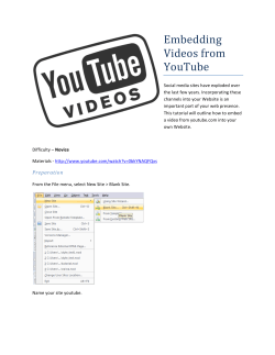

© Copyright 2026