
BL67 – USER MANUAL I/O MODULES
BL67 – USER MANUAL I/O MODULES All brand and product names are trademarks or registered trade marks of the owner concerned. Edition 01/2014 © Hans Turck GmbH, Muelheim an der Ruhr All rights reserved, including those of the translation. No part of this manual may be reproduced in any form (printed, photocopy, microfilm or any other process) or processed, duplicated or distributed by means of electronic systems without written permission of Hans Turck GmbH & Co. KG, Muelheim an der Ruhr. Subject to alterations without notice Table of Contents 1 About this manual 1.1 Documentation concept .................................................................................................................................1-2 1.2 Description of symbols used .........................................................................................................................1-3 1.3 General information........................................................................................................................................1-4 1.3.1 1.3.2 Prescribed use .........................................................................................................................................................................................1-4 Notes concerning planning /installation of this product ........................................................................................................1-4 1.4 List of revisions ................................................................................................................................................1-5 2 BL67-philosophy 2.1 The basic concept ............................................................................................................................................2-2 2.1.1 2.1.2 Flexibility ...................................................................................................................................................................................................2-2 Convenient handling ............................................................................................................................................................................2-2 2.2 BL67 components ............................................................................................................................................2-3 2.2.1 2.2.2 2.2.3 2.2.4 Gateways ...................................................................................................................................................................................................2-3 Electronic modules ................................................................................................................................................................................2-4 Base modules...........................................................................................................................................................................................2-5 End plate ...................................................................................................................................................................................................2-5 3 General technical data of BL67 modules 3.1 Introduction .....................................................................................................................................................3-2 3.2 Technical abbreviations..................................................................................................................................3-3 3.3 Station dimensions .......................................................................................................................................3-4 3.4 General technical data ...................................................................................................................................3-6 3.5 Approvals .........................................................................................................................................................3-8 4 Power Feeding modules 4.1 Overview ..........................................................................................................................................................4-2 4.1.1 Module overview....................................................................................................................................................................................4-2 4.2 BL67-PF-24VDC, with diagnostics .................................................................................................................4-3 4.2.1 4.2.2 4.2.3 4.2.4 Technical data..........................................................................................................................................................................................4-4 Diagnostic/ status messages..............................................................................................................................................................4-5 Module parameters ...............................................................................................................................................................................4-6 Base modules/ pin assignment .........................................................................................................................................................4-6 5 Digital Input Modules 5.1 Overview ..........................................................................................................................................................5-3 5.1.1 Module overview....................................................................................................................................................................................5-3 5.2 BL67-4DI-P .......................................................................................................................................................5-4 5.2.1 5.2.2 5.2.3 5.2.4 Technical data..........................................................................................................................................................................................5-5 diagnostic-/ status messagesDiagnostic/ status messages....................................................................................................5-6 Module parameters ...............................................................................................................................................................................5-6 Base modules/ pin assignment .........................................................................................................................................................5-6 D300529 0114 - BL67 I/O modules i 5.2.5 Signal assignment ...............................................................................................................................................................................5-10 5.3 BL67-4DI-PD .................................................................................................................................................. 5-11 5.3.1 5.3.2 5.3.3 5.3.4 5.3.5 5.3.6 Technical data .......................................................................................................................................................................................5-12 Diagnostic/ status messages ...........................................................................................................................................................5-13 Module parameters.............................................................................................................................................................................5-14 Base modules/ pin assignment.......................................................................................................................................................5-15 Signal assignment ..............................................................................................................................................................................5-18 Sensor supply .......................................................................................................................................................................................5-18 5.4 BL67-8DI-P..................................................................................................................................................... 5-19 5.4.1 5.4.2 5.4.3 5.4.4 5.4.5 Technical data .......................................................................................................................................................................................5-20 Diagnostic/ status messages ...........................................................................................................................................................5-20 Module parameters.............................................................................................................................................................................5-20 Base modules/ pin assignment.......................................................................................................................................................5-21 Signal assignment ...............................................................................................................................................................................5-24 5.5 BL67-8DI-PD .................................................................................................................................................. 5-25 5.5.1 5.5.2 5.5.3 5.5.4 5.5.5 5.5.6 Technical data .......................................................................................................................................................................................5-26 Diagnostic/ status messages ...........................................................................................................................................................5-27 Module parameters.............................................................................................................................................................................5-28 Base modules/ pin assignment.......................................................................................................................................................5-29 Signal assignment ...............................................................................................................................................................................5-31 Sensor Supply........................................................................................................................................................................................5-31 5.6 BL67-4DI-N .................................................................................................................................................... 5-32 5.6.1 5.6.2 5.6.3 5.6.4 5.6.5 Technical data .......................................................................................................................................................................................5-33 Diagnostic/ status messages ...........................................................................................................................................................5-34 Modul Parameters ...............................................................................................................................................................................5-34 Base modules/ pin assignment.......................................................................................................................................................5-34 Signal assignment ...............................................................................................................................................................................5-38 5.7 BL67-8DI-N .................................................................................................................................................... 5-39 5.7.1 5.7.2 5.7.3 5.7.4 5.7.5 Technical data .......................................................................................................................................................................................5-40 Diagnostic/ status messages ...........................................................................................................................................................5-40 Module parameters.............................................................................................................................................................................5-40 Base modules/ pin assignment.......................................................................................................................................................5-41 Signal assignment ...............................................................................................................................................................................5-43 5.8 BL67-16DI-P................................................................................................................................................... 5-44 5.8.1 5.8.2 5.8.3 5.8.4 5.8.5 Technical data .......................................................................................................................................................................................5-45 Diagnostic/ status messages ...........................................................................................................................................................5-45 Module parameters.............................................................................................................................................................................5-45 Base modules/ pin assignment.......................................................................................................................................................5-46 Signal assignment ...............................................................................................................................................................................5-47 6 Analog Input Modules 6.1 Overview.......................................................................................................................................................... 6-3 6.1.1 6.1.2 Analog value representation ............................................................................................................................................................. 6-4 Module overview ................................................................................................................................................................................... 6-6 6.2 BL67-2AI-I, 0/4…20 mA .................................................................................................................................. 6-7 6.2.1 6.2.2 6.2.3 Technical data ......................................................................................................................................................................................... 6-8 Diagnostic/ status messages ............................................................................................................................................................. 6-9 Module parameters (per channel) ................................................................................................................................................... 6-9 ii D300529 0114 - BL67 I/O modules 6.2.4 6.2.5 Base modules/ pin assignment ...................................................................................................................................................... 6-10 Measurement value representation ............................................................................................................................................. 6-11 6.3 BL67-2AI-V, -10/0…+10 V DC ...................................................................................................................... 6-13 6.3.1 6.3.2 6.3.3 6.3.4 6.3.5 Technical data....................................................................................................................................................................................... 6-14 Diagnostic/ status messages........................................................................................................................................................... 6-15 Module parameters (per channel)................................................................................................................................................. 6-16 Base modules/ pin assignment ...................................................................................................................................................... 6-17 Measurement value representation ............................................................................................................................................. 6-18 6.4 BL67-2AI-PT, Pt-/Ni-sensors......................................................................................................................... 6-20 6.4.1 6.4.2 6.4.3 6.4.4 6.4.5 Technical data....................................................................................................................................................................................... 6-21 Diagnostic/ status messages........................................................................................................................................................... 6-22 Module parameters (per channel)................................................................................................................................................. 6-23 Base modules/ pin assignment ...................................................................................................................................................... 6-24 Measurement value representation ............................................................................................................................................. 6-25 6.5 BL67-2AI-TC, thermocouple ........................................................................................................................ 6-27 6.5.1 6.5.2 6.5.3 6.5.4 6.5.5 Technical data ...................................................................................................................................................................................... 6-28 Diagnostic/ status messages........................................................................................................................................................... 6-30 Module parameters (per channel)................................................................................................................................................. 6-31 Base modules/ pin assignment ...................................................................................................................................................... 6-31 Measurement value representation ............................................................................................................................................. 6-32 6.6 BL67-4AI-V/I, voltage/ current..................................................................................................................... 6-34 6.6.1 6.6.2 6.6.3 6.6.4 6.6.5 6.6.6 Technical data ...................................................................................................................................................................................... 6-35 Diagnostic/ status messages........................................................................................................................................................... 6-36 Diagnostics via Software .................................................................................................................................................................. 6-37 Module parameters (per channel) ................................................................................................................................................ 6-38 Measurement value representation ............................................................................................................................................ 6-39 Base Modules/ pin assignment ...................................................................................................................................................... 6-55 6.7 BL67-4AI-TC, thermocouple ........................................................................................................................ 6-57 6.7.1 6.7.2 6.7.3 6.7.4 Diagnostic/ status messages........................................................................................................................................................... 6-59 Module parameters (per channel)................................................................................................................................................. 6-61 Base modules/ pin assignment ...................................................................................................................................................... 6-62 Measurement value representation ............................................................................................................................................. 6-63 7 Digital Output Modules 7.1 Overview ..........................................................................................................................................................7-3 7.1.1 Module overview....................................................................................................................................................................................7-4 7.2 BL67-4DO-0.5A-P.............................................................................................................................................7-5 7.2.1 7.2.2 7.2.3 7.2.4 7.2.5 Technical data..........................................................................................................................................................................................7-6 Diagnostic/ status messages..............................................................................................................................................................7-7 Module parameters ...............................................................................................................................................................................7-8 Base modules/ pin assignment .........................................................................................................................................................7-8 Signal assignment .............................................................................................................................................................................. 7-11 7.3 BL67-4DO-2A-P............................................................................................................................................. 7-12 7.3.1 7.3.2 7.3.3 7.3.4 7.3.5 Technical data....................................................................................................................................................................................... 7-12 Diagnostic/ status messages........................................................................................................................................................... 7-14 Module parameters ............................................................................................................................................................................ 7-14 Base modules/ pin assignment ...................................................................................................................................................... 7-15 Signal assignment............................................................................................................................................................................... 7-18 D300529 0114 - BL67 I/O modules iii 7.4 BL67- 4DO-4A-P ............................................................................................................................................ 7-19 7.4.1 7.4.2 7.4.3 7.4.4 7.4.5 Technical data .......................................................................................................................................................................................7-20 Diagnostic/ status messages ...........................................................................................................................................................7-21 Module parameters.............................................................................................................................................................................7-22 Base modules/ pin assignment.......................................................................................................................................................7-22 Signal assignment ...............................................................................................................................................................................7-25 7.5 BL67-8DO-0.5A-P .......................................................................................................................................... 7-26 7.5.1 7.5.2 7.5.3 7.5.4 7.5.5 Technical data .......................................................................................................................................................................................7-27 Diagnostic/ status messages ...........................................................................................................................................................7-28 Module parameters.............................................................................................................................................................................7-29 Base modules/ pin assignment.......................................................................................................................................................7-29 Signal assignment ...............................................................................................................................................................................7-31 7.6 BL67-16DO-0.1A-P ........................................................................................................................................ 7-32 7.6.1 7.6.2 7.6.3 7.6.4 Technical data .......................................................................................................................................................................................7-33 Diagnostic/ status messages ...........................................................................................................................................................7-34 Module parameters ............................................................................................................................................................................7-35 Base modules/ pin assignment.......................................................................................................................................................7-35 7.7 BL67-4DO-2A-N............................................................................................................................................. 7-37 7.7.1 7.7.2 7.7.3 7.7.4 7.7.5 Technical data .......................................................................................................................................................................................7-38 Diagnostic/ status messages ...........................................................................................................................................................7-39 Module parameters.............................................................................................................................................................................7-40 Base modules/ pin assignment.......................................................................................................................................................7-40 Signal assignment ...............................................................................................................................................................................7-43 7.8 BL67-8DO-0.5A-N.......................................................................................................................................... 7-44 7.8.1 7.8.2 7.8.3 7.8.4 7.8.5 Technical data .......................................................................................................................................................................................7-45 Diagnostic/ status messages ...........................................................................................................................................................7-46 Module parameters.............................................................................................................................................................................7-47 Base modules/ pin assignment.......................................................................................................................................................7-47 Signal assignment ...............................................................................................................................................................................7-49 8 Analog Output Modules 8.1 Overview.......................................................................................................................................................... 8-2 8.1.1 8.1.2 Resolution of analog value representations ................................................................................................................................ 8-2 Module overview ................................................................................................................................................................................... 8-2 8.2 BL67-2AO-I, 0/4...20mA .................................................................................................................................. 8-3 8.2.1 8.2.2 8.2.3 8.2.4 8.2.5 Technical data ......................................................................................................................................................................................... 8-4 Diagnostic/ status messages ............................................................................................................................................................. 8-5 Module parameters (per channel) ................................................................................................................................................... 8-5 Measurement value representation................................................................................................................................................ 8-6 Base modules/ pin assignment.......................................................................................................................................................8-10 8.3 BL67-2AO-V, -10/0…+10V DC ..................................................................................................................... 8-11 8.3.1 8.3.2 8.3.3 8.3.4 8.3.5 Technical data .......................................................................................................................................................................................8-11 Diagnostic/ status messages ...........................................................................................................................................................8-13 Module parameters (per channel) .................................................................................................................................................8-13 Base modules/ pin assignment.......................................................................................................................................................8-14 Measurement value representation..............................................................................................................................................8-14 8.4 BL67-4AO-V, -10/0…+10V DC ..................................................................................................................... 8-16 iv D300529 0114 - BL67 I/O modules 8.4.1 8.4.2 8.4.3 8.4.4 8.4.5 Technical data....................................................................................................................................................................................... 8-17 Diagnostic/ status messages........................................................................................................................................................... 8-18 Module parameters (per channel)................................................................................................................................................. 8-19 Measurement value representation ............................................................................................................................................. 8-20 Base modules/ pin assignment ...................................................................................................................................................... 8-24 9 Digital Combi Modules 9.1 Overview ..........................................................................................................................................................9-2 9.1.1 Module overview....................................................................................................................................................................................9-2 9.2 BL67-4DI4DO-PD .............................................................................................................................................9-3 9.2.1 9.2.2 9.2.3 9.2.4 9.2.5 Technical data .........................................................................................................................................................................................9-5 Diagnostic/ status messages..............................................................................................................................................................9-7 Module parameters ...............................................................................................................................................................................9-8 Base modules/ pin assignment .........................................................................................................................................................9-8 Signal assignment............................................................................................................................................................................... 9-10 9.3 BL67-8XSG-PD .............................................................................................................................................. 9-11 9.3.1 9.3.2 9.3.3 9.3.4 9.3.5 9.3.6 Technical data....................................................................................................................................................................................... 9-12 Diagnostic/ status messages........................................................................................................................................................... 9-14 Module parameters ............................................................................................................................................................................ 9-15 Base modules/ pin assignment ...................................................................................................................................................... 9-15 Signal assignment .............................................................................................................................................................................. 9-19 Sensor supply........................................................................................................................................................................................ 9-19 9.4 BL67-8XSG-P ................................................................................................................................................. 9-20 9.4.1 9.4.2 9.4.3 9.4.4 9.4.5 9.4.6 Technical data....................................................................................................................................................................................... 9-21 Diagnostic/ status messages........................................................................................................................................................... 9-22 Module parameters ............................................................................................................................................................................ 9-23 Base modules/ pin assignment ...................................................................................................................................................... 9-23 Signal assignment .............................................................................................................................................................................. 9-26 Sensor supply........................................................................................................................................................................................ 9-27 10 Analog Combi Modules 10.1 BL67-4AI4AO-V/I, voltage/ current measurement..................................................................................... 10-2 10.1.1 10.1.2 10.1.3 10.1.4 10.1.5 10.1.6 Technical data....................................................................................................................................................................................... 10-3 Diagnostic/ status messages........................................................................................................................................................... 10-5 Module parameters (per channel)................................................................................................................................................. 10-7 Measurement value representation of inputs .......................................................................................................................... 10-8 Measurement value representation of outputs .....................................................................................................................10-21 Base modules/ pin assignment ....................................................................................................................................................10-26 10.2 BL67-2AI2AO-V/I, voltage/ current measurement................................................................................... 10-29 10.2.1 10.2.2 10.2.3 10.2.4 10.2.5 Technical data.....................................................................................................................................................................................10-30 Diagnostic/ status messages.........................................................................................................................................................10-32 Module parameters (per channel)...............................................................................................................................................10-34 Measurement value representation of inputs ........................................................................................................................10-35 Base modules/ pin assignment ....................................................................................................................................................10-35 11 Relay modules 11.1 BL67-8DO-R-NO ............................................................................................................................................ 11-2 11.1.1 Technical data....................................................................................................................................................................................... 11-3 11.1.2 Diagnostic/ status messages........................................................................................................................................................... 11-4 D300529 0114 - BL67 I/O modules v 11.1.3 11.1.4 11.1.5 11.1.6 Modul parameters ...............................................................................................................................................................................11-4 Base moduled/ pin assignment......................................................................................................................................................11-5 Derating ..................................................................................................................................................................................................11-6 Signal assignment ...............................................................................................................................................................................11-6 12 Technology Modules 12.1 BL67-1RS232 ................................................................................................................................................. 12-3 12.1.1 12.1.2 12.1.3 12.1.4 12.1.5 12.1.6 12.1.7 Data transfer method .........................................................................................................................................................................12-3 Data exchange ......................................................................................................................................................................................12-3 Process data...........................................................................................................................................................................................12-3 Technical data .......................................................................................................................................................................................12-9 Diagnostic/ status messages ........................................................................................................................................................ 12-11 Module parameters ......................................................................................................................................................................... 12-12 Base modules/ pin assignment.................................................................................................................................................... 12-14 12.2 BL67-1RS485/422........................................................................................................................................ 12-16 12.2.1 12.2.2 12.2.3 12.2.4 12.2.5 12.2.6 12.2.7 Transmission procedure................................................................................................................................................................. 12-16 Data exchange ................................................................................................................................................................................... 12-16 Process data........................................................................................................................................................................................ 12-16 Technical data .................................................................................................................................................................................... 12-21 Diagnostic/ status messages ........................................................................................................................................................ 12-23 Module parameters ......................................................................................................................................................................... 12-25 Base modules/ pin assignment.................................................................................................................................................... 12-26 12.3 BL67-1SSI..................................................................................................................................................... 12-28 12.3.1 12.3.2 12.3.3 12.3.4 12.3.5 12.3.6 12.3.7 12.3.8 12.3.9 12.3.10 12.3.11 12.3.12 12.3.13 Transmission procedure................................................................................................................................................................. 12-28 Data exchange ................................................................................................................................................................................... 12-28 Internal registers - read and write operations........................................................................................................................ 12-34 Register access and meaning ....................................................................................................................................................... 12-35 Comparison value 1, Comparison value 2 ............................................................................................................................... 12-37 Lower limit, upper limit .................................................................................................................................................................. 12-37 Offset function / load value........................................................................................................................................................... 12-38 Status messages of the SSI encoder........................................................................................................................................... 12-38 Resetting the register bank........................................................................................................................................................... 12-39 Technica data ..................................................................................................................................................................................... 12-40 Diagnostic/ status messages ........................................................................................................................................................ 12-42 Module parameters ......................................................................................................................................................................... 12-43 Base modules/ pin assignment.................................................................................................................................................... 12-44 12.4 BL67-1CVI .................................................................................................................................................... 12-46 12.4.1 12.4.2 12.4.3 12.4.4 12.4.5 12.4.6 Technical data .................................................................................................................................................................................... 12-46 Process data........................................................................................................................................................................................ 12-49 Diagnostic/ status messages ........................................................................................................................................................ 12-49 Module parameters ......................................................................................................................................................................... 12-52 Base modules/ pin assignment.................................................................................................................................................... 12-53 Important notes for using the CVI module.............................................................................................................................. 12-54 12.5 BL67-1CNT/ENC........................................................................................................................................... 12-55 12.5.1 12.5.2 12.5.3 12.5.4 12.5.5 12.5.6 12.5.7 Getting Started .................................................................................................................................................................................. 12-56 Count mode........................................................................................................................................................................................ 12-57 Measurement mode ........................................................................................................................................................................ 12-58 Functions and explanations.......................................................................................................................................................... 12-60 Reset of status bits............................................................................................................................................................................ 12-67 Error acknowledgement................................................................................................................................................................. 12-67 Technical properties ........................................................................................................................................................................ 12-67 vi D300529 0114 - BL67 I/O modules 12.5.8 12.5.9 12.5.10 12.5.11 12.5.12 12.5.13 Parameters of the counter module.............................................................................................................................................12-74 Process data of the module ...........................................................................................................................................................12-78 Internal registers - read and write ...............................................................................................................................................12-81 Schematic diagram of the read sequence................................................................................................................................12-82 Schematic diagram of the write sequence ..............................................................................................................................12-83 Register bank of the module.........................................................................................................................................................12-84 12.6 BL ident® - BL67-2RFID-S/BL670-2RFID-A ................................................................................................. 12-87 13 Mounting and dismounting 13.1 Mechanical mounting .................................................................................................................................. 13-2 13.1.1 General mounting rules .................................................................................................................................................................... 13-2 13.2 Building up a BL67 station .......................................................................................................................... 13-3 13.2.1 13.2.2 13.2.3 13.2.4 13.2.5 13.2.6 13.2.7 13.2.8 13.2.9 Mounting a gateway .......................................................................................................................................................................... 13-3 Mounting a base module ................................................................................................................................................................. 13-3 Mounting the electronic modules ................................................................................................................................................ 13-4 Prevention of false mounting ......................................................................................................................................................... 13-4 End plate................................................................................................................................................................................................. 13-5 Mounting of BL67 directly on the mounting plate ................................................................................................................. 13-6 FE connection ....................................................................................................................................................................................... 13-6 Mounting the BL67-stations on a mounting rail...................................................................................................................... 13-6 Mounting end brackets..................................................................................................................................................................... 13-6 13.3 Dismounting a BL67-station........................................................................................................................ 13-7 13.3.1 13.3.2 13.3.3 13.3.4 13.3.5 13.3.6 13.3.7 Dismounting from the mounting plate ...................................................................................................................................... 13-7 Dismounting from the mounting rail .......................................................................................................................................... 13-7 Dismounting electronic modules.................................................................................................................................................. 13-7 Dismounting the end brackets....................................................................................................................................................... 13-7 Dismounting base modules ........................................................................................................................................................... 13-8 Dismounting the gateway ............................................................................................................................................................... 13-8 Plugging and pulling electronic modules.................................................................................................................................. 13-8 14 Module labeling 14.1 General notes................................................................................................................................................ 14-2 14.1.1 Colors....................................................................................................................................................................................................... 14-2 14.2 Designations/ ident-no. ............................................................................................................................... 14-3 14.3 Channel numbering ..................................................................................................................................... 14-4 14.4 Labeling of the rotary coding switches ...................................................................................................... 14-4 14.5 Labels............................................................................................................................................................. 14-5 15 Appendix 15.1 Nominal current consumption and power loss of the modules ............................................................... 15-2 15.1.1 Nominal current consumption from the module bus (5 V DC) IMB ................................................................................... 15-2 15.1.2 Nominal current consumption from supply terminal (field) IL ........................................................................................... 15-4 15.1.3 Maximum Power Loss of the Modules......................................................................................................................................... 15-6 15.2 Analog Value Representation (Analog Input Modules) ............................................................................ 15-8 15.2.1 Equations for 16 bit representation.............................................................................................................................................. 15-9 15.2.2 Equations for 12 bit representation ..........................................................................................................................................15-15 D300529 0114 - BL67 I/O modules vii 15.3 Analog Value Representation (Analog Output Modules)........................................................................ 15-21 15.3.1 Equations for 16 bit representation ........................................................................................................................................... 15-21 15.3.2 Equations for 12 bit representation .......................................................................................................................................... 15-23 15.4 Ident codes of the BL67-modules ............................................................................................................. 15-26 16 Glossary 17 Index viii D300529 0114 - BL67 I/O modules 1 About this manual 1.1 Documentation concept................................................................................................................. 1-2 1.2 Description of symbols used ......................................................................................................... 1-3 1.3 General information ...................................................................................................................... 1-4 1.3.1 1.3.2 Prescribed use.................................................................................................................................. 1-4 Notes concerning planning /installation of this product................................................................... 1-4 1.4 List of revisions .............................................................................................................................. 1-5 D300529 0114 - BL67 I/O modules 1-1 About this manual 1.1 Documentation concept This manual contains all information about the bus-independent I/O-modules for the modular BL67system. The following chapters contain a short BL67 system description, exact descriptions of the functionality and the technical data for the I/O-modules as well as all general information concerning the whole system as for example mounting/dismounting, labeling etc. Furthermore, this manual contains a short description of the project planning and diagnostics software for TURCK I/O-systems, the software I/O-ASSISTANT. The bus-specific BL67-gateways, the connection to the different automation devices, the maximum system extension as well as all other bus specific information are described in separate manuals. 1-2 D300529 0114 - BL67 I/O modules Description of symbols used 1.2 Description of symbols used Danger This sign can be found next to all notes that indicate a source of hazards. This can refer to danger to personnel or damage to the system (hardware and software) and to the facility. This sign means for the operator: work with extreme caution. Attention This sign can be found next to all notes that indicate a potential hazard. This can refer to possible danger to personnel and damages to the system (hardware and software) and to the facility. Note This sign can be found next to all general notes that supply important information about one or more operating steps. These specific notes are intended to make operation easier and avoid unnecessary work due to incorrect operation. D300529 0114 - BL67 I/O modules 1-3 About this manual 1.3 General information Attention Please read this section carefully. Safety aspects cannot be left to chance when dealing with electrical equipment. 1.3.1 Prescribed use Danger The devices described in this manual must be used only in applications prescribed in this manual or in the respective technical descriptions, and only with certified components and devices from third party manufacturers. Appropriate transport, storage, deployment and mounting as well as careful operating and thorough maintenance guarantee the trouble-free and safe operation of these devices. 1.3.2 Notes concerning planning /installation of this product Danger All respective safety measures and accident protection guidelines must be considered carefully and without exception. 1-4 D300529 0114 - BL67 I/O modules List of revisions 1.4 List of revisions In comparison to the previous manual edition, the following changes/ revisions have been made: Table 1-1: List of revisions Chapter Subject/ Description 5 Module description BL67-16DI-P (page 5-44) 6 Module description BL67-4AI-V/I, voltage/ current (page 6-34): – Diagnostics via Software (page 6-37) – Module parameters (per channel) (page 6-38) – Measurement value representation (page 6-39) Module description BL67-4AI-TC, thermocouple (page 6-57) 8 15 new changed deleted X X X X X Module description BL67-2AO-I, 0/4...20mA (page 8-3): – Module parameters (per channel) (page 8-5) – Measurement value representation (page 8-6) X X Nominal current consumption and power loss of the modules (page 15-2) X Ident codes of the BL67-modules (page 15-26) X Note The publication of this manual renders all previous editions invalid. D300529 0114 - BL67 I/O modules 1-5 About this manual 1-6 D300529 0114 - BL67 I/O modules 2 BL67-philosophy 2.1 The basic concept........................................................................................................................... 2-2 2.1.1 2.1.2 Flexibility ........................................................................................................................................... 2-2 Convenient handling......................................................................................................................... 2-2 2.2 BL67 components........................................................................................................................... 2-3 2.2.1 2.2.2 Gateways.......................................................................................................................................... 2-3 Electronic modules ........................................................................................................................... 2-4 – Power Feeding modules................................................................................................................ 2-4 Base modules................................................................................................................................... 2-5 End plate .......................................................................................................................................... 2-5 2.2.3 2.2.4 D300529 0114 - BL67 I/O modules 2-1 BL67-philosophy 2.1 The basic concept BL67 is a modular IP67 I/O-system for use in industrial automation. It connects the sensors and actuators in the field to the higher-level controller. BL67 offers modules for practically all applications: Digital input and output modules Analog input and output modules Technology modules (RS232 interface, …) A complete BL67 station counts as one station on the bus and therefore occupies one fieldbus address in any given fieldbus structure. A BL67 station consists of a gateway, power distribution modules and I/ O modules. The connection to the relevant fieldbus is made via the bus-specific gateway, which is responsible for the communication between the BL67 station and the other fieldbus stations. The communication within the BL67 station between the gateway and the individual BL67 modules is regulated via an internal module bus. Note The gateway is the only fieldbus-dependent module on a BL67 station. All other BL67 modules are not dependent on the fieldbus used. 2.1.1 Flexibility A BL67 station can contain modules in any combination, which means it is possible to adapt the system to practically all applications in automated industry. 2.1.2 Convenient handling All BL67 modules, with the exception of the gateway, consist of a base module and an electronic module. The gateway and the base modules are snapped onto a mounting rail or are directly mounted onto a mounting plate. The electronic modules are plugged onto the appropriate base modules. After disconnection of the load, the electronic modules can be plugged or pulled when the station is being commissioned or for maintenance purposes, without having to disconnect the field wiring from the base modules. 2-2 D300529 0114 - BL67 I/O modules BL67 components 2.2 BL67 components Figure 2-1: BL67-Station PROFIBUS-DP Agateway Belectronics module Cbase module B C A 2.2.1 Gateways The gateway connects the fieldbus to the I/O modules. It is responsible for handling the entire process data and generates diagnostic information for the higher-level master and the software tool I/O-ASSISTANT. Figure 2-2: Gateway D300529 0114 - BL67 I/O modules 2-3 BL67-philosophy 2.2.2 Electronic modules Electronic modules contain the I/O-functions of the BL67 modules (Power Feeding modules, digital and analog input/output modules and technology modules). Electronic modules are plugged onto the base modules and are not directly connected to the wiring. They can be plugged or pulled when the station is being commissioned or for maintenance purposes, without having to disconnect the field wiring from the base modules. Figure 2-3: Electronic module Power Feeding modules Power Feeding modules distribute the required 24 V DC field voltage to the I/O modules. They are necessary for building groups of modules with different potentials within a BL67 station, or if the rated supply voltage for the outputs cannot be guaranteed. Power Feeding modules are potentially isolated from the gateway, the adjoining power supply module and the I/O modules to the left side. 2-4 D300529 0114 - BL67 I/O modules BL67 components 2.2.3 Base modules The field wiring is connected to the base modules. These are available in miscellaneous connection variations: 1 x M12, 2 x M12, 2 x M12-P, 4 x M12, 4 x M12-P 4 x M8, 8 x M8 1 x M12-8, 2M12-P 1 x 7/8’’ (for Power Feeding modules) etc.. Figure 2-4: Base module 2.2.4 End plate An end plate on the right-hand side physically completes the BL67 station. It protects the module bus contacts of the last base module in a station and guarantees the protection class IP67 when tightly screwed. Figure 2-5: End plate D300529 0114 - BL67 I/O modules 2-5 BL67-philosophy 2-6 D300529 0114 - BL67 I/O modules 3 General technical data of BL67 modules 3.1 Introduction ...................................................................................................................................... 2 3.2 Technical abbreviations.................................................................................................................... 3 3.3 Station dimensions ......................................................................................................................... 4 3.4 General technical data ..................................................................................................................... 6 3.5 Approvals.......................................................................................................................................... 8 D300529 0114 - BL67 I/O modules 3-1 General technical data of BL67 modules 3.1 Introduction The following chapters (chapter 3 to chapter 9) contain all information about the BL67 power supply and I/O modules. This chapter describes the general technical data valid for all BL67 modules. Note The parameter and diagnosis information of the individual modules correspond to those determined in the bus configuration files (GSD- or EDS- files) which are described in the bus specific manuals for the BL67 gateways with PROFIBUS-DP (Turck Documentation-No.: German D300570/ English D300527), with DeviceNet (Turck Documentation-No.: German D300571/ English D300528). Please refer to these manuals for the fieldbus-specific description of the diagnostic and parameter data of the individual BL67 modules. Note The gateway’s technical data and the gateway’s diagnostic options are also described in the bus-specific manuals for the BL67 gateways with PROFIBUS-DP (Turck Documentation-No.: German D300570/ English D300527), with DeviceNet (Turck Documentation-No.: German D300571/ English D300528). An overview of all electronic modules and the appropriate base modules can be found in the „Appendix“. 3.1 Module abbreviations The module designations are explained in the following table: Table 3-1: Module abbreviations 3-2 Abbr. Designation Example AI Analog input module BL67-2AI-I AO Analog output module BL67-2AO-V B Designation for the base modules. B-2M12 DP PROFIBUS-DP BL67-GW-DP I Analog in- or output module for current signals sn(0/4 to 20 mA) P Positive switching (sourcing) BL67-8DO-0.5A-P PF Power Feeding Module BL67-PF-24VDC PT Analog input module for connecting resistance thermometers with sensors PT100, PT200, PT500 and PT1000 in 2- or 3-wire measurement type BL67-2AI-PT RS232 Module with integrated RS232 interface BL67-1RS232 TC Analog input module for connecting thermocouples BL67-2AI-TC V Analog in- or output module for voltage signals (-10/ BL67-2AO-V 0 to 10 V) D300529 0114 - BL67 I/O modules Technical abbreviations 3.2 Technical abbreviations The following abbreviations are used in the technical data and wiring diagrams: Table 3-2: Technical abbreviations Abbr. Designation fT Transmission frequency IA Output current IAmax Maximum output current Iin Input current IK Short circuit current IL Nominal current consumption from power supply (field) IMAX Maximum Input current (destruction limit) IMB Nominal current consumption from the module bus (5 V DC) ISENS Sensor supply fro VI PE Protective earth PMAX Maximum power loss of the modules RE Input resistance RLI Load resistance, inductive RLK Load resistance, capacitive RLL Lamp load RLO Load resistance, ohmic RON Switch-on resistance tAmbient Ambient temperature TK Temperature coefficient tStore Storage temperature UFe Isolation voltage (field/ functional earth) UMAX Maximum input voltage (destruction limit) UTMB Isolation voltage (module bus/ field) VI/UB Supply voltage for inputs/ operating voltage VO/UL Supply voltage for outputs/ load voltage Vsens Sensor supply D300529 0114 - BL67 I/O modules 3-3 General technical data of BL67 modules 3.3 Station dimensions Figure 3-1: Top view 64.5 [2.54] 32.0 [1.26] 32.0 [1.26] ADimensions in mm [inch] 145.0 [5.71] 135.0 [5.31] 32.0 [1.26] 32.5 [1.28] 64.0 [2.52] 32.0 [1.26] 140.0 [5.51] Figure 3-2: Side view ADimensions in mm [inch] 77.5 [3.05] 13.0 [0.51] 3-4 D300529 0114 - BL67 I/O modules Station dimensions Figure 3-3: BL67-module (electronic - and base module) ADimensions in mm [inch] 195.0 [7.68] 185.0 [7.28] 32.0 [1.26] D300529 0114 - BL67 I/O modules 3-5 General technical data of BL67 modules 3.4 General technical data Note The auxiliary power supply must comply with the stipulations of SELV (Safety Extra Low Voltage) according to IEC 364-4-41. Table 3-3: General technical data relating to a station Supply voltage/ auxiliary voltage Demands on the voltage supply acc. to EN 61131-2 Nominal value (provision for other modules) 24 V DC Permissible range according to EN 61 131-2 (18 to 30 V DC) Residual ripple according to EN 61 131-2 Potential isolation Yes, via optocoupler Isolation voltage – field bus/(VI/ VO) – PROFIBUS-DP: 500 Vrms – DeviceNet: no – Ethernet: 500 Vrms – VI/ VO no – (VI/ VO1)/(VI/ VO2), with PF module for potential isolation 500 Vrms – field bus/ (VI/ VO2) 500 Vrms Ambient conditions Ambient temperature 3-6 – tAmbient 0 to +55 °C / 32 to 131 °F – tStore - 25 to +85 °C / - 13 to 185 °F Relative humidity according to IEC 61131-2 Climatic tests according to IEC 61131-2 Noxious gas according to IEC 68068-42/43 Resistance to vibration according to IEC 61131-2 Protection class according to IEC 60529 IP 67 Shock resistant according to IEC 61131-2 Topple and fall/ free fall according to IEC 61131-2 D300529 0114 - BL67 I/O modules General technical data Emitted interference High-frequency, radiated according to EN 55011, Class A Immunity to interference A I/O-line-length ≤ 30 m Static electricity according to IEC 61131-2 Electromagnetic HF fields according to IEC 61131-2 Fast transients (Burst) according to IEC 61131-2 Conducted interferences induced by HF fields according to IEC 61000-4-6 10 V Criteria A High energy transients (Surge) A voltage supply according to IEC 61000-4-5 0.5 kV CM, 12Ω/ 9 μF 0.5 kV DM, 2Ω/ 18 μF Criteria B Reliability Operational life MTBF min. 120 000 h Electronic modules pull/ plug cycles 20 Danger This device can cause radio disturbances in residential areas and in small industrial areas (residential, business and trading). In this case, the operator can be required to take appropriate measures to suppress the disturbance at his own cost. D300529 0114 - BL67 I/O modules 3-7 General technical data of BL67 modules 3.5 Approvals Table 3-4: Approvals Approvals CE CSA (in preparation) UL (in preparation) 3-8 D300529 0114 - BL67 I/O modules 4 Power Feeding modules 4.1 Overview ........................................................................................................................................ 4-2 4.1.1 Module overview .............................................................................................................................. 4-2 4.2 BL67-PF-24VDC, with diagnostics ................................................................................................. 4-3 4.2.1 4.2.2 Technical data .................................................................................................................................. 4-4 Diagnostic/ status messages ........................................................................................................... 4-5 – Diagnosis/ status via LEDs ............................................................................................................ 4-5 – Diagnosis via software................................................................................................................... 4-6 Module parameters .......................................................................................................................... 4-6 Base modules/ pin assignment ........................................................................................................ 4-6 4.2.3 4.2.4 D300529 0114 - BL67 I/O modules 4-1 Power Feeding modules 4.1 Overview Power Feeding modules supply an galvanically isolated 24 V DC field voltage to the I/O modules. By using Power Feeding modules, it is not necessary to distribute power separately to each BL67 I/O module. Power Feeding modules distribute two separately switchable voltages to the modules, one for the inputs (VI) and one for the outputs (VO). These two voltages refer to the same ground potential (GND). A sensor current limitation of 4 A for the input supply VI is integrated in the modules to detect possible short circuits in the sensor supply. The 24 V DC field supply is connected to the Power Feeding module by a 7/8“- connector. LED status indicators Error signals and diagnostic statuses are indicated via LEDs on the module. The corresponding diagnostic information is transmitted to the gateway via diagnostic bits. 4.1.1 Module overview BL67-PF-24VDC 4-2 D300529 0114 - BL67 I/O modules BL67-PF-24VDC, with diagnostics 4.2 BL67-PF-24VDC, with diagnostics Figure 4-1: BL67-PF-24VDC Figure 4-2: Block diagram BL67system bus V0 5 1 Vi 2 3 4 undervoltage detection + - undervoltage detection DIA module bus interface communication bus DIA + - V0 power bus short circuit detection DIA Vsens PE GND D300529 0114 - BL67 I/O modules 4-3 Power Feeding modules 4.2.1 Technical data Table 4-1: Technical data Designation BL67-PF-24VDC Field supply Output supply VO/ UL – Permissible range Input supply VI/ UB – Permissible range – 18 to 30 V DC 24 V DC – 18 to 30 V DC IMB Nominal current from 5 V DC (module bus) ≤ 30 mA Max. output current from VO 10 A Max. input current from VI 4A (limited by internal current limiter) Isolation voltage module bus/ supply voltage 4-4 24 V DC Max. 1000 VDC D300529 0114 - BL67 I/O modules BL67-PF-24VDC, with diagnostics 4.2.2 Diagnostic/ status messages Diagnosis/ status via LEDs Table 4-2: Diagnosis/ status via LEDs LED Display Meaning Remedy D Red, flashing, 0.5 Hz Diagnostics pending – Red Module bus communication failure Check if more than two adjoining electronic modules have been pulled. This applies to modules located between this module and the gateway. Off No error messages or diagnostics – Green Power supply for outputs ok – Off Power supply for outputs faulty Check the wiring to the power supply. Check the external power supply unit. Green Power supply for inputs ok – Off Power supply for inputs faulty Check the wiring to the power supply. Check the external power supply unit. Red short circuit in sensor supply (VI) Check the sensor supply. Off sensor supply (VI) ok VO VI IIim D300529 0114 - BL67 I/O modules - 4-5 Power Feeding modules Diagnosis via software This module has the following diagnostic data: Table 4-3: Diagnostic data 4.2.3 Diagnosis Meaning Current Overflow II Current consumption too high (> 4 A). Low voltage VO VO < 18 VDC Low voltage VI VI < 18 VDC Module parameters none 4.2.4 Base modules/ pin assignment BL67-B-1RSM (7/8’’)/ BL67-B-1RSM-4 Figure 4-3: BL67-B-1RSM/ BL67-B-1RSM-4 Figure 4-4: Pin assignment BL67-PF-24VDC with BL67-B-1RSM 4 3 5 2 1 1 = GND 2 = GND 3 = PE 4 = Vi 5 = Vo module wiring diagram 4A Isens Isens Io Vi 4-6 Vo D300529 0114 - BL67 I/O modules BL67-PF-24VDC, with diagnostics Figure 4-5: Pin assignment BL67-PF-24VDC with BL67-B-1RSM-4 Total current (Isens + Io) max. 10A 1 = Vo, Vi 3 2 = n.c. 4 3 = n.c. 4 = GND 1 2 module wiring diagram 4A Isens Isens Io Vi/Vo Figure 4-6: Pin assignment BL67-PF-24VDC with BL67-B-1RSM-VO 4 3 5 2 1 Only Vo (pin 1 and 5) supply, do not connect pin 2 and 4! 1 = GND 2 = d.n.c. 3 = PE 4 = d.n.c. 5 = Vo module wiring diagram Isens Isens IO Vo D300529 0114 - BL67 I/O modules 4-7 Power Feeding modules 4-8 D300529 0114 - BL67 I/O modules 5 Digital Input Modules 5.1 Overview ........................................................................................................................................... 3 5.1.1 Module overview .................................................................................................................................. 3 5.2 BL67-4DI-P ........................................................................................................................................ 4 5.2.1 5.2.2 5.2.3 5.2.4 5.2.5 Technical data ...................................................................................................................................... 5 diagnostic-/ status messagesDiagnostic/ status messages ................................................................ 6 – Diagnosis/ status via LEDs ................................................................................................................ 6 Module parameters .............................................................................................................................. 6 Base modules/ pin assignment ............................................................................................................ 6 Signal assignment .............................................................................................................................. 10 5.3 BL67-4DI-PD.................................................................................................................................... 11 5.3.1 5.3.2 5.3.3 5.3.4 5.3.5 5.3.6 Technical data .................................................................................................................................... 12 Diagnostic/ status messages ............................................................................................................. 13 – Diagnosis/ status via LEDs .............................................................................................................. 13 – Diagnosis via software..................................................................................................................... 14 Module parameters ............................................................................................................................ 14 Base modules/ pin assignment .......................................................................................................... 15 Signal assignment ............................................................................................................................. 18 Sensor supply .................................................................................................................................... 18 5.4 BL67-8DI-P ...................................................................................................................................... 19 5.4.1 5.4.2 5.4.3 5.4.4 5.4.5 Technical data .................................................................................................................................... 20 Diagnostic/ status messages ............................................................................................................. 20 – Diagnosis/ status via LEDs .............................................................................................................. 20 Module parameters ............................................................................................................................ 20 Base modules/ pin assignment .......................................................................................................... 21 Signal assignment .............................................................................................................................. 24 5.5 BL67-8DI-PD.................................................................................................................................... 25 5.5.1 5.5.2 5.5.3 5.5.4 5.5.5 5.5.6 Technical data .................................................................................................................................... 26 Diagnostic/ status messages ............................................................................................................. 27 – Diagnosis/ status via LEDs .............................................................................................................. 27 – Diagnosis via software..................................................................................................................... 28 Module parameters ............................................................................................................................ 28 Base modules/ pin assignment .......................................................................................................... 29 Signal assignment .............................................................................................................................. 31 Sensor Supply .................................................................................................................................... 31 5.6 BL67-4DI-N ...................................................................................................................................... 32 5.6.1 5.6.2 5.6.3 5.6.4 5.6.5 Technical data .................................................................................................................................... 33 Diagnostic/ status messages ............................................................................................................. 34 – Diagnosis/ status via LEDs .............................................................................................................. 34 Modul Parameters .............................................................................................................................. 34 Base modules/ pin assignment .......................................................................................................... 34 Signal assignment .............................................................................................................................. 38 5.7 BL67-8DI-N ...................................................................................................................................... 39 5.7.1 5.7.2 Technical data .................................................................................................................................... 40 Diagnostic/ status messages ............................................................................................................. 40 D300529 0114 - BL67 I/O modules 5-1 Digital Input Modules 5.7.3 5.7.4 5.7.5 – Diagnosis/ status via LEDs ..............................................................................................................40 Module parameters.............................................................................................................................40 Base modules/ pin assignment ..........................................................................................................41 Signal assignment ..............................................................................................................................43 5.8 BL67-16DI-P .................................................................................................................................... 44 5.8.1 5.8.2 Technical data ....................................................................................................................................45 Diagnostic/ status messages..............................................................................................................45 – Diagnosis/ status via LEDs ..............................................................................................................45 Module parameters.............................................................................................................................45 Base modules/ pin assignment ..........................................................................................................46 Signal assignment ..............................................................................................................................49 5.8.3 5.8.4 5.8.5 5-2 D300529 0114 - BL67 I/O modules Overview 5.1 Overview Digital input modules (DI) detect electrical high- and low-level values through the base module connections and transmit the corresponding digital value to the gateway. The modules provide optically isolated inputs according to IEC 61131 Type 1. The sensor supply (Vsens) is tapped from the internal voltage supply bus. This voltage is supplied by the gateway or a Power Feeding module. Both contain a short circuit detection for the sensor supply voltage. In the modules without diagnostic function a sensor short circuit is thus detected in the gateway or in the Power Feeding module. The modules with diagnostic function (BL67-xDI-PD) provide a short circuit protection. The modules provide reverse polarity protection. LED status indicators modules without channel- or connector-diagnosis: The channel status is indicated via the channel LED. Error signals from the I/O level are indicated by each module via the “D” LED. modules with channel- or connector-diagnosis: The modules BL67-xDI-PD provide wether a channel- or a connector diagnosis function. Diagnosis information are indicated via the channel LED or via the "D" LED. 5.1.1 Module overview Table 5-1: Module overview Module Number of channels positive switching, sinking BL67-4DI-P 4 BL67-8DI-P 8 BL67-4DI-N 4 - BL67-8DI-N 8 - BL67-4DI-PD 4 BL67-8DI-PD 8 BL67-16DI-P 16 D300529 0114 - BL67 I/O modules 5-3 Digital Input Modules 5.2 BL67-4DI-P Figure 5-1: BL67-4DI-P Figure 5-2: Block diagram Vsens IN 1 BL67system bus Vsens 1 module bus interface Vsens PE GND 5-4 V0 Vsens Vsens IN 4 communication bus 4 power bus Vsens PE GND D300529 0114 - BL67 I/O modules BL67-4DI-P 5.2.1 Technical data Table 5-2: Technical data Designation BL67-4DI-P Number of channels 4 Input voltage, nominal value at 24 V DC Low level < 4.5 V High level 7 V < Uin < 9 V Nominal current from 5 V DC (module bus) IMB ≤ 30 mA Nominal current from supply terminal IL ≤ 40 mA Power loss of the module < 250 mW Input current Iin Low level < 0.5 mA High level > 3.7 mA Isolation voltage UTMB (module bus/ field) D300529 0114 - BL67 I/O modules max. 1000 V DC 5-5 Digital Input Modules 5.2.2 diagnostic-/ status messagesDiagnostic/ status messages Diagnosis/ status via LEDs Table 5-3: Diagnosis/ status via LEDs LED Display Meaning Remedy D Red Module bus communication failure Check if more than two ad-joining electronic modules have been pulled. This concerns modules located between this module and the gateway. Off No error messages – Green Status of channel x = „1“ – Off Status of channel x = „0“ - 0 to 3 5.2.3 Module parameters None 5.2.4 Base modules/ pin assignment BL67-B-4M8 Figure 5-3: BL67-B-4M8 Figure 5-4: Pin assignment BL67-4DI-P with BL67-B-4M8 v 4 3 5-6 1 1 = VSENS 3 = GND 4 = Input A D300529 0114 - BL67 I/O modules BL67-4DI-P Figure 5-5: Wiring diagram BL67-4DI-P with BL67-B-4M8 1 (+) BN 4 ( ) BK 3 () BU BL67-B-2M12/ BL67-B-2M12-P (paired) Figure 5-6: BL67-B-2M12/ BL67-B-2M12-P Figure 5-7: Pin assignment BL67-4DI-P with BL67-B-2M12/ BL67-B-2M12-P v 2 3 1 5 4 D300529 0114 - BL67 I/O modules 1 = VSENS 2 = Input B 3 = GND 4 = Input A 5 = PE 5-7 Digital Input Modules Figure 5-8: Wiring diagrams BL67-4DI-P with BL67-B-2M12/ BL67-B-2M12-P 1 (+) BN 2 ( ) WH 3 () BU 4 ( ) BK 5 1 (+) BN 2 ( ) WH 3 () BU 4 ( ) BK 5 BL67-B-4M12 Figure 5-9: BL67-B-4M12 Figure 5-10: Pin assignment BL67-4DI-P with BL67-B-4M12 v 2 3 1 5 5-8 4 1 = VSENS 2 = n.c. 3 = GND 4 = Input A 5 = PE D300529 0114 - BL67 I/O modules BL67-4DI-P Figure 5-11: Wiring diagram BL67-4DI-P with BL67-B-4M12 3 () BU 4 ( ) BK 1 (+) BN 5 BL67-1M23 Figure 5-12: BL67-B-1M23 Figure 5-13: Pin assignment BL67-4DI-P with BL67-B-1M23 v 1 9 8 2 10 12 7 3 11 4 5 6 1 = Signal 0 2 = Signal 1 3 = Signal 2 4 = Signal 3 5 = n.c. 6 = n.c. D300529 0114 - BL67 I/O modules 7 = n.c. 8 = n.c. 9 = VSENS 10 = VSENS 11 = VSENS 12 = GND 5-9 Digital Input Modules 5.2.5 Signal assignment Table 5-4: Signal assignment with BL67-B4M8 Table 5-5: Signal assignment with BL67-B2M12 Table 5-6: Signal assignment with BL67-B-2M12-P Table 5-7: Signal assignment with BL67-B-4M12 Table 5-8: Signal assignment with BL67-B-1M23 Byte Bit 7 Bit 6 Bit 5 Bit 4 Bit 3 Bit 2 Bit 1 Bit 0 n - - - - C3P4 C2P4 C1P4 C0P4 Byte Bit 7 Bit 6 Bit 5 Bit 4 Bit 3 Bit 2 Bit 1 Bit 0 n - - - - C1P2 C0P2 C1P4 C0P4 Byte Bit 7 Bit 6 Bit 5 Bit 4 Bit 3 Bit 2 Bit 1 Bit 0 n - - - - C1P2 C1P4 C0P2 C0P4 Byte Bit 7 Bit 6 Bit 5 Bit 4 Bit 3 Bit 2 Bit 1 Bit 0 n - - - - C3P4 C2P4 C1P4 C0P4 Byte Bit 7 Bit 6 Bit 5 Bit 4 Bit 3 Bit 2 Bit 1 Bit 0 n - - - - C0P4 C0P3 C0P2 C0P1 In In In In In n = process data offset of the input data depending on station configuration and the corresponding fieldbus. C… = slot no. P… = pin no. 5-10 D300529 0114 - BL67 I/O modules BL67-4DI-PD 5.3 BL67-4DI-PD Figure 5-14: BL67-4DI-PD Figure 5-15: Block diagram BL67system bus IN1 1 Vsens IN4 module bus interface 4 Vsens V0 DIA VsensA communication bus >I power bus Vsens PE GND VsensD >I PE GND D300529 0114 - BL67 I/O modules 5-11 Digital Input Modules 5.3.1 Technical data Table 5-9: Technical data Designation BL67-4DI-PD Number of channels 4 Input voltage, nominal value at 24 V DC Low level < 4.5 V High level > 7 V (max. 30 V) Nominal current from 5 V DC (module bus) IMB ≤ 30 mA Nominal current from supply terminal IL ≤ 100 mA (all inputs low) Power loss of the module < 1.5 W Input current Iin Low level < 1.5 mA High level > 3.7 mA Isolation voltage 5-12 UTMB (module bus/ field) max. 2500 V DC UFE max. 1000 V DC D300529 0114 - BL67 I/O modules BL67-4DI-PD 5.3.2 Diagnostic/ status messages Diagnosis/ status via LEDs Table 5-10: Diagnosis via LEDs LED Display Meaning Remedy D Red Module bus communication failure Check if more than two ad-joining electronic modules have been pulled. This concerns modules located between this module and the gateway. Red Error in field supply (LED VI at Power Feeding module is „off“) Check the power supply for the inputs (Vsens). 0 to 3 Red, Diagnosis pending flashing, 0.5 Hz - Off No error messages – Green Status of channel x = „1“ Green Off Status of channel x = „0“ Off Red flashing, 2 Hz LED 0 to 3: Overload sensor supply x – Check the sensor supply. Red LED 0 and 1: open-circuit monitoring – Check the wires for open-circuits. D300529 0114 - BL67 I/O modules 5-13 Digital Input Modules Diagnosis via software This module has the following diagnostic data available per channel: Diagnosis Table 5-11: Diangosis 5.3.3 Overcurrent/ short circuit sensor x Overcurrent at sensor supply (> 100 mA). Open circuit Kx Groupwise open-circuit monitoring: Group A (channel 0 and 2) Group B (channel 1 and 3). Module parameters Table 5-12: Module parameters Adefault setting Parameter name Value Meaning Input filter x deactivate A Input filter: 0,25 ms. activate Input filter: 2.5 ms normalA Input signal not inverted inverted Input signal inverted, Conversion of the effective signal direction for sensors Digital input x Operation mode group x normalA open-circuit monitoring 5-14 open-circuit monitoring: Group A (channel 0 and 2) Group B (channel 1 and 3). D300529 0114 - BL67 I/O modules BL67-4DI-PD 5.3.4 Base modules/ pin assignment BL67-B-4M8 Figure 5-16: BL67-B-4M8 Figure 5-17: Pin assignment BL67-4DI-PD with BL67-B-4M8 v 4 3 1 Figure 5-18: Wiring diagram BL67-4DI-PD with BL67-B-4M8 D300529 0114 - BL67 I/O modules 1 = VSENS 3 = GND 4 = Input A 1 (+) BN 4 ( ) BK 3 () BU 5-15 Digital Input Modules BL67-B-2M12/ BL67-B-2M12-P (paired) Figure 5-19: BL67-B-2M12/ BL67-B-2M12-P Figure 5-20: Pin assignment BL67-4DI-PD with BL67-B-2M12/ BL67-B-2M12-P v 2 5 Figure 5-21: Wiring diagrams BL67-4DI-PD with BL67-B-2M12/ BL67-B-2M12-P 4 1 (+) BN 2 ( ) WH 3 () BU 5 5 5-16 3 1 1 = VSENS 2 = Input B 3 = GND 4 = Input A 5 = PE 4 ( ) BK 1 (+) BN 2 ( ) WH 3 () BU 4 ( ) BK D300529 0114 - BL67 I/O modules BL67-4DI-PD Figure 5-22: If the open circuit detection has been activated, a jumper between pin 1 (24 VDC) and pin 2 (diagnostics input) must Wiring diagram for be implemented on the sensor side for monitoring of wire-breaks. open circuit detection only with 1 (+) BN base module BL67B-2M12 2 ( ) WH 3 () BU 4 ( ) BK 5 BL67-B-4M12 Figure 5-23: BL67-B-4M12 Figure 5-24: Pin assignment BL67-4DI-PD with BL67-B-4M12 v 3 1 5 Figure 5-25: Wiring diagram BL67-4DI-PD with BL67-B-4M12 1 = VSENS 2 = n.c. 3 = GND 4 = Input A 5 = PE 2 5 4 3 () BU 4 ( ) BK 1 (+) BN D300529 0114 - BL67 I/O modules 5-17 Digital Input Modules 5.3.5 Signal assignment Table 5-13: Signal assignment with BL67-B4M8 Table 5-14: Signal assignmen with BL67-B-2M12 incl. wire break diagnosis Table 5-15: Signal assignmen with BL67-B-2M12-P Table 5-16: Signal assignmen with BL67-B-4M12 Byte Bit 7 Bit 6 Bit 5 Bit 4 Bit 3 Bit 2 Bit 1 Bit 0 n - - - - C3P4 C2P4 C1P4 C0P4 Byte Bit 7 Bit 6 Bit 5 Bit 4 Bit 3 Bit 2 Bit 1 Bit 0 n - - - - C1P2 C0P2 C1P4 C0P4 - - - - Byte Bit 7 Bit 6 Bit 5 Bit 4 Bit 3 Bit 2 Bit 1 Bit 0 n - - - - C1P2 C1P4 C0P2 C0P4 Byte Bit 7 Bit 6 Bit 5 Bit 4 Bit 3 Bit 2 Bit 1 Bit 0 n - - - - C3P4 C2P4 C1P4 C0P4 In In In In wire break 1+2 Sensor signal 1 + 2 n = process data offset of the input data depending on station configuration and the corresponding fieldbus. C… = slot no. P… = pin no. 5.3.6 Sensor supply Table 5-17: Sensor supply 5-18 Vsens A B C D BL67-B-2M12 C0P1 C1P1 - - BL67-B-2M12-P C0P1 C1P1 - - BL67-B-4M12 C0P1 C1P1 C2P1 C3P1 BL67-B-4M8 C0P1 C1P1 C2P1 C3P1 D300529 0114 - BL67 I/O modules BL67-8DI-P 5.4 BL67-8DI-P Figure 5-26: BL67-8DI-P Figure 5-27: Block diagram Vsens IN 1 BL67system bus Vsens 1 module bus interface Vsens PE GND D300529 0114 - BL67 I/O modules V0 Vsens Vsens IN 8 communication bus 8 power bus Vsens PE GND 5-19 Digital Input Modules 5.4.1 Technical data Table 5-18: Technical data Designation BL67-8DI-P Number of channels 8 Input voltage, nominal value at 24 V DC Low level < 4.5 V High level 7 V < Uin < 9 V Nominal current from 5 V DC (module bus) IMB < 30 mA Nominal current from supply terminal IL ≤ 40 mA Power loss of the module < 250 mW Input current Iin Low level < 0.5 mA High level > 3.7 mA Isolation voltage UTMB (module bus/ field) 5.4.2 max. 1000 V DC Diagnostic/ status messages Diagnosis/ status via LEDs Table 5-19: Diagnosis/ status via LEDs LED Display Meaning Remedy D Red Module bus communication failure Check if more than two adjoining electronic modules have been pulled. This concerns modules located between this module and the gateway. Off No error messages – Green Status of channel x = „1“ – Off Status of channel x = „0“ - 0 to 7 5.4.3 Module parameters None 5-20 D300529 0114 - BL67 I/O modules BL67-8DI-P 5.4.4 Base modules/ pin assignment BL67-B-8M8 Figure 5-28: BL67-B-8M8 Figure 5-29: Pin assignment BL67-8DI-P with BL67-B-8M8 v 4 3 1 Figure 5-30: Wiring diagram BL67-8DI-P with BL67-B-8M8 D300529 0114 - BL67 I/O modules 1 = VSENS 3 = GND 4 = Input A 1 (+) BN 4 ( ) BK 3 () BU 5-21 Digital Input Modules BL67-B-4M12/ BL67-B-4M12-P (paired) Figure 5-31: BL67-B-4M12/ BL67-B-4M12-P Figure 5-32: Pin assignment BL67-8DI-P with BL67-B-4M12/ BL67-B-4M12-P v 2 3 1 5 Figure 5-33: Wiring diagrams BL67-8DI-P with BL67-B-4M12/ BL67-B-4M12-P 1 (+) BN 2 ( ) WH 3 () BU 5 5 5-22 4 1 = VSENS 2 = Input B 3 = GND 4 = Input A 5 = PE 4 ( ) BK 1 (+) BN 2 ( ) WH 3 () BU 4 ( ) BK D300529 0114 - BL67 I/O modules BL67-8DI-P BL67-1M23 Figure 5-34: BL67-B-1M23 Figure 5-35: Pin assignment BL67-8DI-P with BL67-B-1M23 v 1 9 8 2 10 12 7 3 11 4 5 6 1 = Signal 0 2 = Signal 1 3 = Signal 2 4 = Signal 3 5 = Signal 4 6 = Signal 5 D300529 0114 - BL67 I/O modules 7 = Signal 6 8 = Signal 7 9 = VSENS 10 = VSENS 11 = VSENS 12 = GND 5-23 Digital Input Modules 5.4.5 Signal assignment Table 5-20: Signal assignment with BL67-B8M8 Table 5-21: Signal assignment with BL67-B4M12 Table 5-22: Signal assignment with BL67-B-4M12-P Table 5-23: Signal assignment with t BL67-B-1M23 In In In In Byte Bit 7 Bit 6 Bit 5 Bit 4 Bit 3 Bit 2 Bit 1 Bit 0 n C7P4 C6P4 C5P4 C4P4 C3P4 C2P4 C1P4 C0P4 Byte Bit 7 Bit 6 Bit 5 Bit 4 Bit 3 Bit 2 Bit 1 Bit 0 n C3P2 C2P2 C1P2 C0P2 C3P4 C2P4 C1P4 C0P4 Byte Bit 7 Bit 6 Bit 5 Bit 4 Bit 3 Bit 2 Bit 1 Bit 0 n C3P2 C3P4 C2P2 C2P4 C1P2 C1P4 C0P2 C0P4 Byte Bit 7 Bit 6 Bit 5 Bit 4 Bit 3 Bit 2 Bit 1 Bit 0 n C0P8 C0P7 C0P6 C0P5 C0P4 C0P3 C0P2 C0P1 n = process data offset of the input data depending on station configuration and the corresponding fieldbus. C… = slot no. P… = pin no. 5-24 D300529 0114 - BL67 I/O modules BL67-8DI-PD 5.5 BL67-8DI-PD Figure 5-36: BL67-8DI-PD Figure 5-37: Block diagram BL67system bus IN1 1 Vsens IN8 module bus interface 8 Vsens V0 DIA VsensA communication bus >I power bus Vsens PE GND VsensD >I PE GND D300529 0114 - BL67 I/O modules 5-25 Digital Input Modules 5.5.1 Technical data Table 5-24: Technical data Designation BL67-8DI-PD Number of channels 8 Input voltage, nominal value at 24 V DC Low level < 4.5 V High level > 7 V (max. 30 V) Nominal current from 5 V DC (module bus) IMB ≤ 30 mA Nominal current from supply terminal IL ≤ 100 mA (all inputs low) Power loss of the module < 1.5 W Input current Iin Low level < 1.5 mA High level > 3.7 mA Isolation voltage 5-26 UTMB (module bus/ field) max. 2500 V DC UFE max. 1000 V DC D300529 0114 - BL67 I/O modules BL67-8DI-PD 5.5.2 Diagnostic/ status messages Diagnosis/ status via LEDs Table 5-25: Diagnosis via LEDs LED Display Meaning Remedy D Red Module bus communication failure Check if more than two ad-joining electronic modules have been pulled. This concerns modules located between this module and the gateway. Red Error in field supply Check the power supply for the inputs (Vsens). (LED VI at Power Feeding module is „off“) 0 to 7 Red, Diagnosis pending flashing, 0.5 Hz - Off No error messages – Green Status of channel x = „1“ Green Off Status of channel x = „0“ Off Red flashing, 2 Hz LED 0 to 7: Overload sensor supply x – Check the sensor supply. Red LED 0 to 3 open-circuit monitoring – Check the wires for open-circuit. D300529 0114 - BL67 I/O modules 5-27 Digital Input Modules Diagnosis via software This module has the following diagnostic data available per channel: Table 5-26: Diangosis 5.5.3 Table 5-27: Module parameters Diagnosis Overcurrent/ short circuit sensor x Overcurrent at sensor supply (> 100 mA). Open circuit Kx Groupwise open-circuit monitoring: Group A (channel 0 and 4) Group B (channel 1 and 5) Group C (channel 3 and 6) Group D (channel 4 and 7). Module parameters Parameter name Value Meaning Input filter x deactivate A Input filter: 0,25 ms. activate Input filter: 2.5 ms normalA Input signal not inverted inverted Input signal inverted, Conversion of the effective signal direction for sensors Adefault setting Digital input x Operation mode group x normal open-circuit monitoring 5-28 open-circuit monitoring: Group A (channel 0 and 4) Group B (channel 1 and 5) Group C (channel 3 and 6) Group D (channel 4 and 7). D300529 0114 - BL67 I/O modules BL67-8DI-PD 5.5.4 Base modules/ pin assignment BL67-B-8M8 Figure 5-38: BL67-B-8M8 Figure 5-39: Pin assignment BL67-8DI-PD with BL67-B-8M8 v 4 3 1 Figure 5-40: Wiring diagram BL67-8DI-PD with BL67-B-8M8 D300529 0114 - BL67 I/O modules 1 = VSENS 3 = GND 4 = Input A 1 (+) BN 4 ( ) BK 3 () BU 5-29 Digital Input Modules BL67-B-4M12/ BL67-B-4M12-P (paired) Figure 5-41: BL67-B-4M12/ BL67-B-4M12-P Figure 5-42: Pin assignment BL67-8DI-PD with BL67-B-4M12/ BL67-B-4M12-P v 2 3 1 5 Figure 5-43: Wiring diagrams BL67-8DI-PD with BL67-B-4M12/ BL67-B-4M12-P 1 (+) BN 2 ( ) WH 3 () BU 5 5 5-30 4 1 = VSENS 2 = Input B 3 = GND 4 = Input A 5 = PE 4 ( ) BK 1 (+) BN 2 ( ) WH 3 () BU 4 ( ) BK D300529 0114 - BL67 I/O modules BL67-8DI-PD Figure 5-44: If the open circuit detection has been activated, a jumper between pin 1 (24 VDC) and pin 2 (diagnostics input) must Wiring diagram for be implemented on the sensor side for monitoring of wire-breaks. open circuit detection only with 1 (+) BN base module BL67B-2M12 2 ( ) WH 3 () BU 4 ( ) BK 5 5.5.5 Signal assignment Table 5-28: Signal assignment with BL67-B8M8 Table 5-29: Signal assignment with BL67-B4M12 Table 5-30: Signal assignment with BL67-B-4M12-P Byte Bit 7 Bit 6 Bit 5 Bit 4 Bit 3 Bit 2 Bit 1 Bit 0 n C7P4 C6P4 C5P4 C4P4 C3P4 C2P4 C1P4 C0P4 Byte Bit 7 Bit 6 Bit 5 Bit 4 Bit 3 Bit 2 Bit 1 Bit 0 n C3P2 C2P2 C1P2 C0P2 C3P4 C2P4 C1P4 C0P4 In In Wire break1 to 4 Sensor signal 1 to 4 Byte Bit 7 Bit 6 Bit 5 Bit 4 Bit 3 Bit 2 Bit 1 Bit 0 n C3P2 C3P4 C2P2 C2P4 C1P2 C1P4 C0P2 C0P4 In n = process data offset of the input data depending on station configuration and the corresponding fieldbus. C… = slot no. P… = pin no. 5.5.6 Sensor Supply Table 5-31: Sensor Supply Vsens A B C D BL67-B-4M12 C0P1 C1P1 C2P1 C3P1 BL67-B-4M12-P C0P1 C1P1 C2P1 C3P1 BL67-B-8M8 C0P1/ C1P1 C2P1/ C3P1 C4P1/ C5P1 C6P1/ C7P1 D300529 0114 - BL67 I/O modules 5-31 Digital Input Modules 5.6 BL67-4DI-N Figure 5-45: BL67-4DI-N Figure 5-46: Block diagram Vsens IN 1 BL67system bus Vsens 1 module bus interface Vsens PE GND 5-32 V0 Vsens Vsens IN 4 communication bus 4 power bus Vsens PE GND D300529 0114 - BL67 I/O modules BL67-4DI-N 5.6.1 Technical data Table 5-32: Technical data Designation BL67-4DI-N Number of channels 4 Input voltage, nominal value at 24 V DC Low level > 7 V (max. 30 V) High level <5V Nominal current from 5 V DC (module bus) IMB ≤ 30 mA Nominal current from supply terminal IL ≤ 1 mA (all inputs low) Power loss of the module < 1.3 W Input current Iin Low level < 2.5 mA High level > 3 mA Isolation voltage UTMB (module bus/ field) max. 2500 V DC UFE max. 1000 V DC D300529 0114 - BL67 I/O modules 5-33 Digital Input Modules 5.6.2 Diagnostic/ status messages Diagnosis/ status via LEDs Table 5-33: Diagnosis/ status via LEDs LED Display Meaning Remedy D Red Module bus communication failure Check if more than two ad-joining electronic modules have been pulled. This concerns modules located between this module and the gateway. Off No error messages – Green Status of channel x = „1“ – Off Status of channel x = „0“ - 0 to 3 5.6.3 Modul Parameters None 5.6.4 Base modules/ pin assignment BL67-B-4M8 Figure 5-47: BL67-B-4M8 Figure 5-48: Pin assignment BL67-4DI-N with BL67-B-4M8 v 4 3 5-34 1 1 = VSENS 3 = GND 4 = Input A D300529 0114 - BL67 I/O modules BL67-4DI-N Figure 5-49: Wiring diagram BL67-4DI-N with BL67-B-4M8 1 (+) BN 4 ( ) BK 3 () BU BL67-B-2M12/ BL67-B-2M12-P (paired) Figure 5-50: BL67-B-2M12/ BL67-B-2M12-P Figure 5-51: Pin assignment BL67-4DI-N with BL67-B-2M12/ BL67-B-2M12-P v 2 3 1 5 4 D300529 0114 - BL67 I/O modules 1 = VSENS 2 = Input B 3 = GND 4 = Input A 5 = PE 5-35 Digital Input Modules Figure 5-52: Wiring diagrams BL67-4DI-N with BL67-B-2M12/ BL67-B-2M12-P 1 (+) BN 2 ( ) WH 3 () BU 4 ( ) BK 5 1 (+) BN 2 ( ) WH 3 () BU 4 ( ) BK 5 BL67-B-4M12 Figure 5-53: BL67-B-4M12 Figure 5-54: Pin assignment BL67-4DI-N with BL67-B-4M12 v 2 3 1 5 5-36 4 1 = VSENS 2 = n.c. 3 = GND 4 = Input A 5 = PE D300529 0114 - BL67 I/O modules BL67-4DI-N Figure 5-55: Wiring diagram BL67-4DI-N with BL67-B-4M12 3 () BU 4 ( ) BK 1 (+) BN 5 BL67-1M23 Figure 5-56: BL67-B-1M23 Figure 5-57: Pin assignment BL67-4DI-N with BL67-B-1M23 v 1 9 8 2 10 12 7 3 11 4 5 6 1 = Signal 0 2 = Signal 1 3 = Signal 2 4 = Signal 3 5 = n.c. 6 = n.c. D300529 0114 - BL67 I/O modules 7 = n.c. 8 = n.c. 9 = VSENS 10 = VSENS 11 = VSENS 12 = GND 5-37 Digital Input Modules 5.6.5 Signal assignment Table 5-34: Signal assignment with BL67-B4M8 Table 5-35: Signal assignment with BL67-B2M12 Table 5-36: Signal assignment with BL67-B-2M12-P Table 5-37: Signal assignment with BL67-B-4M12 Table 5-38: Signal assignment with BL67-B-1M232 (-VI) Byte Bit 7 Bit 6 Bit 5 Bit 4 Bit 3 Bit 2 Bit 1 Bit 0 n - - - - C3P4 C2P4 C1P4 C0P4 Byte Bit 7 Bit 6 Bit 5 Bit 4 Bit 3 Bit 2 Bit 1 Bit 0 n - - - - C1P2 C0P2 C1P4 C0P4 Byte Bit 7 Bit 6 Bit 5 Bit 4 Bit 3 Bit 2 Bit 1 Bit 0 n - - - - C1P2 C1P4 C0P2 C0P4 Byte Bit 7 Bit 6 Bit 5 Bit 4 Bit 3 Bit 2 Bit 1 Bit 0 n - - - - C3P4 C2P4 C1P4 C0P4 Byte Bit 7 Bit 6 Bit 5 Bit 4 Bit 3 Bit 2 Bit 1 Bit 0 n - - - - C0P4 C0P3 C0P2 C0P1 In In In In In n = process data offset of the input data depending on station configuration and the corresponding fieldbus. C… = slot no. P… = pin no. 5-38 D300529 0114 - BL67 I/O modules BL67-8DI-N 5.7 BL67-8DI-N Figure 5-58: BL67-8DI-N Figure 5-59: Block diagram Vsens IN 1 BL67system bus Vsens 1 module bus interface Vsens PE GND D300529 0114 - BL67 I/O modules V0 Vsens Vsens IN 8 communication bus 8 power bus Vsens PE GND 5-39 Digital Input Modules 5.7.1 Technical data Table 5-39: Technical data Designation BL67-8DI-N Number of channels 8 Input voltage, nominal value at 24 V DC Low level > 7 V (max. 30 V) High level <5V Nominal current from 5 V DC (module bus) IMB ≤ 30 mA Nominal current from supply terminal IL ≤ 1 mA (all inputs low) Power loss of the module < 1.3 W Input current Iin Low level < 1.2 mA High level > 1.5 mA Isolation voltage 5.7.2 UTMB (module bus/ field) max. 2500 V DC UFE max. 1000 V DC Diagnostic/ status messages Diagnosis/ status via LEDs Table 5-40: Diagnosis/ status via LEDs LED Display Meaning Remedy D Red Module bus communication failure Check if more than two ad-joining electronic modules have been pulled. This concerns modules located between this module and the gateway. Off No error messages – Green Status of channel x = „1“ – Off Status of channel x = „0“ - 0 to 7 5.7.3 Module parameters None 5-40 D300529 0114 - BL67 I/O modules BL67-8DI-N 5.7.4 Base modules/ pin assignment BL67-B-8M8 Figure 5-60: BL67-B-8M8 Figure 5-61: Pin assignment BL67-8DI-N with BL67-B-8M8 v 4 3 Figure 5-62: Wiring diagram BL67-8DI-N with BL67-B-8M8 1 1 = VSENS 3 = GND 4 = Input A 1 (+) BN 4 ( ) BK 3 () BU D300529 0114 - BL67 I/O modules 5-41 Digital Input Modules BL67-B-4M12/ BL67-B-4M12-P (paired) Figure 5-63: BL67-B-4M12/ BL67-B-4M12-P Figure 5-64: Pin assignment BL67-8DI-N with BL67-B-4M12/ BL67-B-4M12-P v 2 3 1 5 Figure 5-65: Wiring diagrams BL67-8DI-N with BL67-B-4M12/ BL67-B-4M12-P 1 (+) BN 2 ( ) WH 3 () BU 5 5 5-42 4 1 = VSENS 2 = Input B 3 = GND 4 = Input A 5 = PE 4 ( ) BK 1 (+) BN 2 ( ) WH 3 () BU 4 ( ) BK D300529 0114 - BL67 I/O modules BL67-8DI-N BL67-1M23 Figure 5-66: BL67-B-1M23 Figure 5-67: Pin assignment BL67-8DI-N with BL67-B-1M23 v 3 5.7.5 1 = Signal 0 2 = Signal 1 3 = Signal 2 4 = Signal 3 5 = Signal 4 6 = Signal 5 1 9 8 2 10 12 7 11 4 5 6 7 = Signal 6 8 = Signal 7 9 = VSENS 10 = VSENS 11 = VSENS 12 = GND Signal assignment Table 5-41: Signal assignment with BL67-B8M8 Table 5-42: Signal assignment with BL67-B4M12 Table 5-43: Signal assignment with BL67-B-4M12-P Table 5-44: Signal assignment with BL67-B-1M23(-VI) Byte Bit 7 Bit 6 Bit 5 Bit 4 Bit 3 Bit 2 Bit 1 Bit 0 n C7P4 C6P4 C5P4 C4P4 C3P4 C2P4 C1P4 C0P4 Byte Bit 7 Bit 6 Bit 5 Bit 4 Bit 3 Bit 2 Bit 1 Bit 0 n C3P2 C2P2 C1P2 C0P2 C3P4 C2P4 C1P4 C0P4 Byte Bit 7 Bit 6 Bit 5 Bit 4 Bit 3 Bit 2 Bit 1 Bit 0 n C3P2 C3P4 C2P2 C2P4 C1P2 C1P4 C0P2 C0P4 Byte Bit 7 Bit 6 Bit 5 Bit 4 Bit 3 Bit 2 Bit 1 Bit 0 n C0P8 C0P7 C0P6 C0P5 C0P4 C0P3 C0P2 C0P1 In In In In n = process data offset of the input data depending on station configuration and the corresponding fieldbus. C… = slot no. P… = pin no. D300529 0114 - BL67 I/O modules 5-43 Digital Input Modules 5.8 BL67-16DI-P Figure 5-68: BL67-16DI-P Figure 5-69: Block diagram Vsens IN 1 BL67system bus Vsens 1 module bus interface Vsens Vsens IN 16 PE GND 5-44 communication bus V0 Vsens 16 power bus Vsens PE GND D300529 0114 - BL67 I/O modules BL67-16DI-P 5.8.1 Technical data Table 5-45: Technical data Designation BL67-16DI-P Number of channels 16 Input voltage, nominal value at 24 V DC Low level < 4,5 V High level > 7 V (max. 30 V) Nominal current from 5 V DC (module bus) IMB ≤ 30 mA Nominal current from supply terminal IL ≤ 3 mA, all inputs low mMx. sensor supply Isens 4 A, via gateway or Power-Feeding module, electronically short circuit limited Power loss of the module < 100 mW Input current Iin Low level < 0.5 mA High level 2,1 to 3,7 mA Isolation voltage U (module bus/ field) 5.8.2 max. 500 V DC Diagnostic/ status messages Diagnosis/ status via LEDs Table 5-46: Diagnosis/ status via LEDs LED Display Meaning Remedy D Red Module bus communication failure Check if more than two adjoining electronic modules have been pulled. This concerns modules located between this module and the gateway. Off No error messages – Green Status of channel 0 to 7 = 1 – Orange Status of channel 8 to 15 = 1 Off Status of channel x = 0 0 to 7 5.8.3 - Module parameters None D300529 0114 - BL67 I/O modules 5-45 Digital Input Modules 5.8.4 Base modules/ pin assignment BL67-B-8M8-4-P Figure 5-70: BL67-B-8M8-4-P Figure 5-71: Pin assignment BL67-8DI-P with BL67-B-8M8-4-P v 4 3 1 = VSENS 2 = Signal A 3 = GND 4 = Signal B 2 1 BL67-1M23 Figure 5-72: BL67-B-1M23-19 Figure 5-73: Pin assignment BL67-16DI-P with BL67-B-1M23-19 v 1 2 3 4 13 14 5 5-46 12 18 19 15 6 11 17 16 7 10 9 8 1 = Input 14 2 = Input 10 3 = Input 6 4 = Input 3 5 = Input 2 6 = GND 7 = Input 1 8 = Input 5 9 = Input 9 10 = Input 13 11 = Input 12 12 = PE 13 = Input 11 14 = Input 7 15 = Input 0 16 = Input 4 17 = Input 8 18 = Input 15 19 = VSENS D300529 0114 - BL67 I/O modules BL67-16DI-P 5.8.5 Signal assignment Table 5-47: Signal assignment with BL67-B-8M8-4-P Table 5-48: Signal assignment with BL67-B-1M23-19 In In Byte Bit 7 Bit 6 Bit 5 Bit 4 Bit 3 Bit 2 Bit 1 Bit 0 n C3P2 C3P4 C2P2 C2P4 C1P2 C1P4 C0P2 C0P4 Byte Bit 15 Bit 14 Bit 13 Bit 12 Bit 11 Bit 10 Bit 9 Bit 8 n C7P2 C7P4 C6P2 C6P4 C5P2 C5P4 C4P2 C4P4 Byte Bit 7 Bit 6 Bit 5 Bit 4 Bit 3 Bit 2 Bit 1 Bit 0 n C0P14 C0P3 C0P8 C0P16 C0P4 C0P5 C0P7 C0P15 Byte Bit 15 Bit 14 Bit 13 Bit 12 Bit 11 Bit 10 Bit 9 Bit 8 n C0P18 C0P1 C0P10 C0P11 C0P13 C0P2 C0P9 C0P17 n = process data offset of the input data depending on station configuration and the corresponding fieldbus. C… = slot no. P… = pin no. D300529 0114 - BL67 I/O modules 5-47 Digital Input Modules 5-48 D300529 0114 - BL67 I/O modules 6 Analog Input Modules 6.1 Overview ........................................................................................................................................... 3 6.1.1 6.1.2 Analog value representation ................................................................................................................. 4 Module overview .................................................................................................................................. 6 6.2 BL67-2AI-I, 0/4…20 mA..................................................................................................................... 7 6.2.1 6.2.2 Technical data ...................................................................................................................................... 8 Diagnostic/ status messages ............................................................................................................... 9 – Diagnosis/ status via LEDs ................................................................................................................ 9 – Diagnosis via software....................................................................................................................... 9 Module parameters (per channel)......................................................................................................... 9 Base modules/ pin assignment .......................................................................................................... 10 Measurement value representation .................................................................................................... 11 – 16 bit value representation .............................................................................................................. 11 – 12 bit value representation (left-justified) ........................................................................................ 12 6.2.3 6.2.4 6.2.5 6.3 BL67-2AI-V, -10/0…+10 V DC .......................................................................................................... 13 6.3.1 6.3.2 Technical data .................................................................................................................................... 14 Diagnostic/ status messages ............................................................................................................. 15 – Diagnosis/ status via LEDs .............................................................................................................. 15 – Diagnosis via software..................................................................................................................... 15 Module parameters (per channel)....................................................................................................... 16 Base modules/ pin assignment .......................................................................................................... 17 Measurement value representation .................................................................................................... 18 – 16-bit-representation....................................................................................................................... 18 – 12 bit representation (left-justified).................................................................................................. 19 6.3.3 6.3.4 6.3.5 6.4 BL67-2AI-PT, Pt-/Ni-sensors ............................................................................................................ 20 6.4.1 6.4.2 Technical data .................................................................................................................................... 21 Diagnostic/ status messages ............................................................................................................. 22 – Diagnosis/ status via LEDs .............................................................................................................. 22 – Diagnosis via software..................................................................................................................... 22 Module parameters (per channel)....................................................................................................... 23 Base modules/ pin assignment .......................................................................................................... 24 Measurement value representation .................................................................................................... 25 – 16-bit-representation....................................................................................................................... 25 – 12 bit representation (left-justified).................................................................................................. 26 6.4.3 6.4.4 6.4.5 6.5 BL67-2AI-TC, thermocouple............................................................................................................ 27 6.5.1 6.5.2 Technical data ................................................................................................................................... 28 Diagnostic/ status messages ............................................................................................................. 30 – Diagnosis/ status via LEDs .............................................................................................................. 30 – Diagnosis via software..................................................................................................................... 30 Module parameters (per channel)....................................................................................................... 31 Base modules/ pin assignment .......................................................................................................... 31 Measurement value representation .................................................................................................... 32 – 16-bit-representation....................................................................................................................... 32 – 12 bit representation (left-justified).................................................................................................. 33 6.5.3 6.5.4 6.5.5 6.6 BL67-4AI-V/I, voltage/ current ........................................................................................................ 34 6.6.1 Technical data ................................................................................................................................... 35 D300529 0114 - BL67 I/O modules 6-1 Analog Input Modules 6.6.2 6.6.3 6.6.4 6.6.5 6.6.6 Diagnostic/ status messages..............................................................................................................36 Diagnostics via Software ....................................................................................................................37 Module parameters (per channel) ......................................................................................................38 Measurement value representation ...................................................................................................39 – Standard value representation ........................................................................................................39 – Extended Range - value representation ..........................................................................................43 – Value representation process automation (NE 43) ..........................................................................49 Base Modules/ pin assignment ..........................................................................................................55 6.7 BL67-4AI-TC, thermocouple............................................................................................................ 57 6.7.1 6.7.2 6.7.3 6.7.4 6-2 – Technical data .................................................................................................................................58 – Basic error and repeat accuracies...................................................................................................59 Diagnostic/ status messages..............................................................................................................59 – Diagnosis/ status via LEDs ..............................................................................................................59 Module parameters (per channel).......................................................................................................61 Base modules/ pin assignment ..........................................................................................................62 Measurement value representation ....................................................................................................63 – Temperature measurment ...............................................................................................................63 – Voltage measurement......................................................................................................................64 D300529 0114 - BL67 I/O modules Overview 6.1 Overview Analog input modules (AI) detect standard electrical signals, digitalize them and transmit the corresponding measurement values to the gateway via the internal module bus. The sensor supply (VI) is tapped from the internal voltage supply bus. This voltage is supplied by the gateway or a Power Feeding module. Both contain a short circuit detection for the sensor supply voltage. A sensor short circuit is thus also detected in the gateway or in the Power Feeding module. The module bus electronic of the analog input modules are galvanically isolated from the field level via an optocoupler and provide reverse polarity protection. Supported signal ranges BL67-2AI-I: 0 to 20 mA 4 to 20 mA BL67-2AI-V: 0 to 10 V DC -10 to 10 V DC Connectable sensors BL67-2AI-PT platinum sensors (PT100, PT200, PT500, PT1000) nickel sensor (Ni100, Ni1000) BL67-2AI-TC thermo elements (of types B, E, J, K, N, R, S, T) LED status indicators Error signals from the I/O level are indicated by each module via the “D” LED. The corresponding diagnostic information is transmitted to the gateway via diagnostic bits. D300529 0114 - BL67 I/O modules 6-3 Analog Input Modules 6.1.1 Analog value representation The analog values can either be represented with16 bit or 12 bit. The two's-complement representation allows the representation of positive as well as negative values. 16-bit-representation The 16-bit-representation is realizes as a two's-complement. 2 byte of process data are completely occupied.: Figure 6-1: 16 bit representation 12 bit representation In the voltage measurement/ output and in the temperature measurement, the value is represented as a two's-complement. In the current measurement/ output and in the resistance measurement, the value is represented as a dual number. The 12 bit value is left-justified and occupies bit 15 to 4 of the process data. Figure 6-2: 12 bit representation The diagnosis information is integrated in the process input data and occupies 4 bit (right-justified). Note A detailed description of the measurement value representation for the analog input modules in 16 or 12 bit can be found in the "appendix" of this manual, page 15-1. 6-4 D300529 0114 - BL67 I/O modules Overview The figure shows a 5-digit binary code in the outer circuit. The inner circuit shows the respective dual number, if the binary code is interpreted as binary number (positive numerical values) and as two’s complement. Figure 6-3: Binary code as binary number and two’s complement D300529 0114 - BL67 I/O modules 6-5 Analog Input Modules 6.1.2 Module overview Table 6-1: Module overview 6-6 Module Number of channels BL67-2AI-I 2 BL67-2AI-V 2 BL67-2AI-PT 2 BL67-2AI-TC 2 BL67-4AI-V/I 4 BL67-4AI-TC 4 D300529 0114 - BL67 I/O modules BL67-2AI-I, 0/4…20 mA 6.2 BL67-2AI-I, 0/4…20 mA Figure 6-4: BL67-2AI-I Table 6-2: Block diagram BL67system bus M12 1 Vsens 2 + - AI+ 3 GND 4 AI- 5 PE multiplexer signal conditioning module bus interface communication bus ADconverter 1 Vsens 2 + - AI+ 3 GND 4 AI- 5 PE V0 power bus Vsens PE GND D300529 0114 - BL67 I/O modules 6-7 Analog Input Modules 6.2.1 Technical data Table 6-3: Technical data Designation BL67-2AI-I Number of channels 2 Nominal voltage from supply terminal 24 V DC voltage range 18 to 30 VDC Nominal current from 5 V DC (module bus) IMB ≤ 35 mA Nominal current from supply terminal IL ≤ 12 mA Power loss of the module, typical PMAX <1W Input current 0/4 to 20 mA Max. input current 50 mA Isolation voltage 6-8 UTMB (module bus/ field) min. 500 Vrms UFe (field/ functional earth) min. 50 VAC channel/channel no channel/field supply no channel/system supply 500 Vrms Input resistance (burden) < 125 Ω Cutoff frequency (-3 dB) ≥ 50 Hz Basic error at 23 °C/ 73.4 °F 0.2 % Repeat accurancy 0.05 % Temperature coefficient ≤ 300 ppm/°C Resolution of the A/D converter 16 Bit Measuring principle Delta Sigma Measurement value representation 16 Bit Signed Integer / 2 Bit Full Range left-justified ISENS (sensor supply from Vi) ≤ 250 mA; short-circuit protection in gateway or Power Feeding module D300529 0114 - BL67 I/O modules BL67-2AI-I, 0/4…20 mA 6.2.2 Diagnostic/ status messages Diagnosis/ status via LEDs Table 6-4: LED Diagnosis via LED D Display Meaning Remedy Red, flashing, 0.5 Hz Diagnostics pending - Red Module bus communication failure Check if more than two ad-joining electronic modules have been pulled. This applies to modules located between this module and the gateway. Off No error messages or diagnostics – Diagnosis via software This module has the following diagnostic data available per channel: Table 6-5: Diagnosis Diagnosis Measurement value range error – Overcurrent: Imax (I > 20.2 mA) – Undercurrent: Imin (I < 3.8 mA) Open circuit (I < 3 mA) Indicates an over- or undercurrent of 1 % of the set current range; „Undercurrent“ is only detected when the current range is set from 4 to 20 mA. Indicates an open circuit in the signal line for the operating mode 4 to 20 mA Note If the measurement value representation is parameterized as „12bit (left-justified)“ the diagnostic data will be transferred with the process data bits 0 to 3 of the respective channel. 6.2.3 Table 6-6: Module parameters Module parameters (per channel) Parameter name Value Value representation integer (15bit + sign)A 12bit (left-justified) Adefault settings Current mode 0…20mA A 4…20mA Channel activateA deactivate Diagnostic release A) block D300529 0114 - BL67 I/O modules 6-9 Analog Input Modules 6.2.4 Base modules/ pin assignment BL67-B-2M12 Figure 6-5: BL67-B-2M12 Figure 6-6: v Pin assignment BL67-2AI-I 2 3 1 5 6-10 4 1 = VSENS 2 = AI + 3 = GND 4 = AI 5 = PE D300529 0114 - BL67 I/O modules BL67-2AI-I, 0/4…20 mA Figure 6-7: Wiring diagrams BL67-2AI-I 2-wire sensor with power supply via base module: 2 + 1 3 I 4 5 3-wire sensor with power supply via base module: + U/I + 2 1 5 3 4 4-wire sensor with power supply via base module: 2 1 5 3 + U/I + U/I 4 4-wire sensor with external power supply: 2 1 5 6.2.5 3 4 + U/I + U/I Measurement value representation 16 bit value representation Current values from 0 to 20 mA The value range 0 mA to 20 mA is displayed as follows: 0000hex to 7FFFhex (decimal: 0 to 32767) Current values from 4 to 20 mA The value range 4 mA to 20 mA is displayed as follows: 0000hex to 7FFFhex (decimal: 0 to 32767) D300529 0114 - BL67 I/O modules 6-11 Analog Input Modules 12 bit value representation (left-justified) Current values from 0 to 20 mA The value range 0 mA to 20 mA is displayed as follows: 000(0)hex to FFF(0)hex (decimal: 0 to 4095) Current values from 4 to 20 mA The value range 4 mA to 20 mA is displayed as follows: 000(0)hex to FFF(0)hex (decimal: 0 to 4095) Note A detailed description of the measurement value representation for the analog input modules in 16 or 12 bit can be found in the "appendix" of this manual, page 15-1. 6-12 D300529 0114 - BL67 I/O modules BL67-2AI-V, -10/0…+10 V DC 6.3 BL67-2AI-V, -10/0…+10 V DC Figure 6-8: BL67-2AI-V Figure 6-9: Block diagram BL67system bus M12 1 Vsens 2 + = - AI+ 3 GND 4 AI- 5 PE multiplexer signal conditioning module bus interface communication bus ADconverter 1 Vsens 2 + = - AI+ 3 GND 4 AI- 5 PE V0 power bus Vsens PE GND D300529 0114 - BL67 I/O modules 6-13 Analog Input Modules 6.3.1 Technical data Table 6-7: Technical data Designation BL67-2AI-V Number of channels 2 Nominal voltage from supply terminal 24 V DC voltage range 18 to 30 VD Nominal current from 5 V DC (module bus) IMB ≤ 35 mA Nominal current from supply terminal IL ≤ 12 mA Power loss of the module, typical PMAX <1W Input voltage -10/0 to 10 VDC Max. input voltage 35 V continuous Isolation voltage 6-14 UTMB (module bus/ field) min. 500 Vrms UFe (field/ functional earth) min. 50 VAC channel/channel no channel/field supply no channel/system supply 500 Vrms Input resistance (burden) ≥ 98.5 kΩ Cutoff frequency (-3 dB) ≥ 50 Hz Basic error at 23 °C/ 73.4 °F 0.2 % Repeat accurancy 0.05 % Temperature coefficient ≤ 150 ppm/°C Resolution of the A/D converter 16 Bit Measuring principle Delta Sigma Measurement value representation 16 Bit Signed Integer / 12 Bit Full Range left-justified ISENS (sensor supply from VI) ≤ 250 mA; short circuit protection in gateway or Power Feeding module D300529 0114 - BL67 I/O modules BL67-2AI-V, -10/0…+10 V DC 6.3.2 Diagnostic/ status messages Diagnosis/ status via LEDs Table 6-8: LED Diagnosis via LED D Display Meaning Remedy Red, flashing, 0.5 Hz Diagnostics pending - Red Module bus communication failure Check if more than two ad-joining electronic modules have been pulled. This applies to modules located between this module and the gateway. Off No error messages or diagnostics – Diagnosis via software This module has the following diagnostic data available per channel: Table 6-9: Diagnosis Diagnosis Measurement value range error Overvoltage: – Umax (U > 10.1 V) Indicates an over- or undervoltage of 1 % of the set voltage range; Undervoltage: – Umin (U < -10.1 V) at -10 to +10 V DC – Umin (U < -0.1 V) at 0 to +10 V DC Note If the measurement value representation is parameterized as „12bit (left-justified)“ the diagnostic data will be transferred with the process data bits 0 to 3 of the respective channel. D300529 0114 - BL67 I/O modules 6-15 Analog Input Modules 6.3.3 Table 6-10: Module parameters Module parameters (per channel) Parameter name Value Value representation integer (15bit + sign)A Adefault settings 12bit (left-justified) Voltage mode -10…+10V 0…10V A Channel activateA deactivate Diagnostic release A block 6-16 D300529 0114 - BL67 I/O modules BL67-2AI-V, -10/0…+10 V DC 6.3.4 Base modules/ pin assignment BL67-B-2M12 Figure 6-10: BL67-B-2M12 Figure 6-11: v Pin assignment BL67-2AI-V 2 3 1 5 4 D300529 0114 - BL67 I/O modules 1 = VSENS 2 = AI + 3 = GND 4 = AI 5 = PE 6-17 Analog Input Modules Figure 6-12: Wiring diagrams BL67-2AI-V 2-wire sensor with power supply via base module: 2 + 1 3 I 4 5 3-wire sensor with power supply via base module: + U/I + 2 1 5 3 4 4-wire sensor with power supply via base module: 2 1 5 3 + U/I + U/I 4 4-wire sensor with external power supply: 2 1 5 6.3.5 3 + U/I + U/I 4 Measurement value representation 16-bit-representation Voltage values from 0 to 10 V DC The value range 0 V DC to 10 V DC is displayed as follows: 0000hex to 7FFFhex (decimal: 0 to 32767) Voltage values from -10 to 10 V DC The value range -10 V to -3.052 10-4 V is displayed as follows: 8000hex to FFFFhex (decimal:-32768 to -1) The value range 0 V to 10 V is displayed as follows: 0000hex to 7FFFhex (decimal: 0 to 32767) 6-18 D300529 0114 - BL67 I/O modules BL67-2AI-V, -10/0…+10 V DC 12 bit representation (left-justified) Voltage values from 0 to 10 V DC The value range 0 V to 10 V is displayed as follows: 000(0)hex to FFF(0)hex (decimal: 0 to 4095) Voltage values from -10 to 10 V DC The value range 0 V to 10 V is displayed as follows: 000(0)hex to 7FF(0)hex (decimal: 0 to 2047) Note A detailed description of the measurement value representation for the analog input modules in 16 or 12 bit can be found in the "appendix" of this manual, page 15-1. D300529 0114 - BL67 I/O modules 6-19 Analog Input Modules 6.4 BL67-2AI-PT, Pt-/Ni-sensors Figure 6-13: BL67-2AI-PT Figure 6-14: Block diagram BL67system bus M12 é é 1 S+ 2 AI+ 3 GND 4 AI- 5 PE 1 S+ 2 AI+ multiplexer signal conditioning module bus interface communication bus ADconverter V0 3 GND 4 AI- 5 PE power bus Vsens PE GND 6-20 D300529 0114 - BL67 I/O modules BL67-2AI-PT, Pt-/Ni-sensors 6.4.1 Technical data Table 6-11: Technical data Designation BL67-2AI-PT Number of channels 2 Nominal voltage from supply terminal 24 V DC voltage range 18 to 30 VDC Nominal current from 5 V DC (module bus) IMB ≤ 45 mA Nominal current from supply terminal IL < 30 mA Power loss of the module, typical PMAX <1W Measurement current < 1 mA Max. input voltage UMAX (Destruction limit) > 30 VDC Isolation voltage UTMB (module bus/ field) min. 500 Vrms UFe (field/ functional earth) min. 50 VAC channel/channel no channel/field supply no channel/system supply 500 Vrms Measurement value representation 16 Bit signed integer / 12 Bit full range left-justified Offset error ≤ 0.1 % Linearity < 0.1 % Basic error at 23 °C / 73.4 °F < 0.2 % from end value Repeat accuracy 0.05 % Temperature coefficient ≤ 300 ppm/°C from end value tCYCL (Cycle time) ≤ 130 ms per channel Connectable sensors Platinum sensors PT100, PT200, PT500, PT1000 Nickel sensors Ni100, Ni1000 D300529 0114 - BL67 I/O modules 6-21 Analog Input Modules 6.4.2 Diagnostic/ status messages Diagnosis/ status via LEDs Table 6-12: LED Diagnosis via LED D Display Meaning Remedy Red, flashing, 0.5 Hz Diagnostics pending - Red Module bus communication failure Check if more than two ad-joining electronic modules have been pulled. This applies to modules located between this module and the gateway. Off No error messages or diagnostics – Diagnosis via software This module has the following diagnostic data available per channel: Table 6-13: Diagnosis Diagnosis Meaning Overflow/ Underflow Threshold: 1 % of positive measurement range end value. Underflow diagnostic only in the temperature measurement range. Open circuit Short-circuit Threshold: 5 Ω (loop resistance) Only with temperature measurements. Note 3-wire measurements with PT100 sensors cannot differentiate between a short-circuit and an open circuit at temperatures below -177 °C. In this case, the diagnostic “Short-circuit“ is generated. 6-22 D300529 0114 - BL67 I/O modules BL67-2AI-PT, Pt-/Ni-sensors 6.4.3 Table 6-14: Module parameters Module parameters (per channel) Parameter name Value Mains suppression 50 Hz A Adefault settings 60 Hz Value representation Integer (15Bit + sign)A 12 Bit (left-justified) Diagnostic release A block Channel activate A deactivate Element PT100, -200…850°C A PT100, -200…150°C NI100, -60…250°C NI100, -60…150°C PT200, -200…850°C PT200, -200…150°C PT500, -200…850°C PT500, -200…150°C PT1000, -200…850°C PT1000, -200…150°C NI1000, -60…250°C NI1000, -60…150°C Resistance, 0…100Ω Resistance, 0…200Ω Resistance, 0…400Ω Resistance, 0…1000Ω Measurement mode 2-wire A 3-wire D300529 0114 - BL67 I/O modules 6-23 Analog Input Modules 6.4.4 Base modules/ pin assignment BL67-B-2M12 Abbildung 7: BL67-B-2M12 Table 6-15: Pinbelegung BL67-2AI-PT v 2 3 1 5 Table 6-16: Anschlussbilder BL67-2AI-PT 4 1=S+ 2 = PT + 3 = GND 4 = PT 5 = PE 2-wire-connection technology: 2 (PT +) 4 (PT ) PT/NI 5 3-wire-connection technology: 1 (S +) 2 (PT +) 4 (PT ) PT/NI 5 6-24 D300529 0114 - BL67 I/O modules BL67-2AI-PT, Pt-/Ni-sensors 6.4.5 Measurement value representation 16-bit-representation For the parameterization "PT100, -200…850°C" "NI100, -60…250°C" "PT200, -200…850°C" "PT500, -200…850°C" "PT1000, -200…850°C" "NI1000, -60…250°C" The value range -200 °C to -0.1°C is displayed as follows: F830hex to FFFFhex (decimal: -2000 to -1) The value range 0 °C to 850°C is displayed as follows: 0000hex to 2134hex (decimal: 0 to 8500) For the parameterization "PT100, -200…150°C" "NI100, -60…150°C" "PT200, -200…150°C" "PT500, -200…150°C" "PT1000, -200…150°C" "NI1000, -60…150°C" The value range -200 °C to -0,01°C is displayed as follows: B1E0hex to FFFFhex (decimal: -20000 to -1) The value range 0 °C to 150°C is displayed as follows: 0000hex to 3A98hex (decimal: 0 to 15000) For representation of resistance values only positive numbers (hexadecimal/binary) are used. The positive values can easily be converted into decimal ones. The value range 0 to 100 Ω; 0 to 200 Ω; 0 to 400 Ω; 0 to 1000 Ω is displayed as follows: 0000hex to 7FFFhex (decimal: 0 to 32767) D300529 0114 - BL67 I/O modules 6-25 Analog Input Modules 12 bit representation (left-justified) For the parameterization: "PT100, -200…850°C" "NI100, -60…250°C" "PT200, -200…850°C" "PT500, -200…850°C" "PT1000, -200…850°C" "NI1000, -60…250°C The value range -200 °C to -0.5°C is displayed as follows: E70(0)hex to FF(0)Fhex (decimal: -400 to -1) The value range 0 °C to 850°C is displayed as follows: 00(0)0hex to 6A4(0)hex (decimal: 0 to 1700) For the parameterization: "PT100, -200…150°C" "NI100, -60…150°C" "PT200, -200…150°C" "PT500, -200…150°C" "PT1000, -200…150°C" "NI1000, -60…150°C" The value range -200 °C to -0.1°C is displayed as follows: 830(0)hex to FFF(0)hex (decimal: -2000 to -1) The value range 0 °C to 150°C is displayed as follows: 000(0)hex to 5DC(0)hex (decimal: 0 to 1500) The value range 0 Ω to 100 Ω; 0 Ω to 200 Ω; 0 Ω to 400 Ω; 0 Ω to 1000 ΩW; is displayed as follows: 000(0)hex to FFF(0)hex (decimal: 0 to 4095) Note A detailed description of the measurement value representation for the analog input modules in 16 or 12 bit can be found in the "appendix" of this manual, page 15-1. 6-26 D300529 0114 - BL67 I/O modules BL67-2AI-TC, thermocouple 6.5 BL67-2AI-TC, thermocouple Figure 6-1: BL67-2AI-TC Figure 6-2: Block diagram BL67system bus M12 J é 1 S+ 2 AI+ 3 GND 4 AI- 5 PE multiplexer signal conditioning module bus interface communication bus ADconverter 1 J é 1 S+ 2 AI+ V0 3 GND 4 AI- 5 PE power bus = = 1 Vsens PE GND cold junction compensation resistance (Pt1000) in male connector D300529 0114 - BL67 I/O modules 6-27 Analog Input Modules 6.5.1 Technical data Table 6-17: Technical data Designation BL67-2AI-TC Number of channels 2 Nominal voltage from supply terminal 24 V DC voltage range 18 to 30 VDC Nominal current from 5 V DC (module bus) IMB ≤ 35 mA Nominal current from supply terminal IL < 30 mA Power loss of the module, typical PMAX <1W Input voltage ≥ 10 VDC (continuous) Isolation voltage UTMB (module bus/ field) min. 500 Vrms UFe (field/ functional earth) min. 50 VAC channel/channel no channel/field supply 500 Vrms channel/system supply 500 Vrms Sensors according to DIN IEC 584 Class 1. 2, 3 Temperature ranges Type B Type E Type J Type K Type N Type R Type S Type T 100 to 1820.0 °C -270 to 1000.0 °C -210 to 1200.0 °C -270 to 1370.0 °C -270 to 1300.0 °C -50 to 1760.0 °C -50 to 1540.0 °C -270 to 400.0 °C Voltage measurements (resolution) ± 50 mV ± 100 mV ± 500 mV ±1V 6-28 < 2 μV < 4 μV < 20 μV < 50 μV Measurement value representation 16 Bit signed integer / 12 Bit full range leftjustified Basic error at 23 °C / 73.4 °F Please refer to Table 6-18 below D300529 0114 - BL67 I/O modules BL67-2AI-TC, thermocouple Table 6-18: Basic errors Table 6-19: Repeat accuracies Crosstalk suppression ≥ 80 dB Repeat accuracy Please refer to Table 6-19: below Temperature coefficient TK ≤ 300 ppm/°C from end value Cycle time Voltage measurement: – 70 ms/ channel Temperature measurement: – 130 ms/ channel Thermocouple Temperature range/ °C Basic error at 23°C /% of positive end value Type K -200…1370 0.2 Type J -210…1200 0.2 Type B 500…1820 0.2 Type N -150…1300 0.2 Type E -180…1000 0.2 Type R 0…1760 0.2 Type S 0…1540 0.2 Type T -200…0 0…400 0.6 0.2 Voltage measurement all measurement ranges 0.2 Thermocouple Repeat accuracy/ % of positive end value Error due to cold junction compensation/ % of positive end value Type K 0.05 0.15 Type J 0.05 0.17 Type B 0.05 0.11 Type N 0.05 0.16 Type E 0.05 0.20 Type R 0.05 0.12 Type S 0.05 0.13 Type T 0.1 0.075 – 0.50 Voltage measurement 0.05 – Note In the lower measurement range, wider deviations for the cold junction compensation have to be expected. D300529 0114 - BL67 I/O modules 6-29 Analog Input Modules 6.5.2 Diagnostic/ status messages Diagnosis/ status via LEDs Table 6-20: LED Diagnosis via LED D Display Meaning Remedy Red, flashing, 0.5 Hz Diagnostics pending - Red Module bus communication failure Check if more than two ad-joining electronic modules have been pulled. This applies to modules located between this module and the gateway. Off No error messages or diagnostics – Diagnosis via software This module has the following diagnostic data available per channel: Table 6-21: Diagnosis 6-30 Diagnosis Measurement value range error – Overflow – Underflow Threshold: 1 % of positive measurement range end value Open circuit Threshold: negative transformer end value Only with temperature measurements. No PT1000 sensor (cold junction compensation) A cold junction temperature of 23°C is automatically presumed. D300529 0114 - BL67 I/O modules BL67-2AI-TC, thermocouple 6.5.3 Module parameters (per channel) Table 6-22: Module parameters Parameter name Value Mains suppression 50 Hz A 60 Hz Adefault settings Value representation Integer (15Bit + sign) A 12Bit (left-justified) Diagnostic release A block Channel activateA deactivate Element 6.5.4 type K, -270…1370°C A type B, +100…1820°C type E, -270…1000°C type J, -210…1200°C type N, -270…1300°C type R, -50…1760°C type S, -50…1540°C type T, -270…400°C +/-50mV +/-100mV +/-500mV +/-1000mV Base modules/ pin assignment BL67-B-2M12 Figure 6-3: BL67-B-2M12 D300529 0114 - BL67 I/O modules 6-31 Analog Input Modules Table 6-23: Pin assignment BL67-2AI-TC v 2 3 1 5 Table 6-24: Wiring diagram BL67-2AI-TC 4 1=S+ 2 = TC + 3 = GND 4 = TC / S 5 = PE 1 (S +) 2 (TC +) 4 (S ) 5 6.5.5 S = PT1000-sensor for cold junction compensation TC = thermo element Pt1000 4 (TC ) TC Measurement value representation 16-bit-representation For the parameterization "Typ K, -270…1370°C" "Typ B, +100…1820°C" "Typ E, -270…1000°C" "Typ J, -210…1200°C" "Typ N, -270…1300°C" "Typ R, -50…1760°C" "Typ S, -50…1540°C" "Typ T, -270…400°C" The value range -270 °C to -0.1°C is displayed as follows: F574hex to FFFFhex (decimal: -2700 to -1) The value range 0 °C to 1820°C is displayed as follows: 0000hex to 4718hex (decimal: 0 to 18200) The value range -50 mV to -0,002 mV; -100 mV to -0,003 mV; -500 mV to -0,015 mV; -1000 mV to -0,031 mV is displayed as follows: 8000hex to FFFFhex (decimal: -32768 to -1) 6-32 D300529 0114 - BL67 I/O modules BL67-2AI-TC, thermocouple The value range 0 mV to 50 mV; 0 mV to 100 mV; 0 mV to 500 mV; 0 mV to 1000 mV; is displayed as follows: 0000hex to7FFFhex (decimal: 0 to 32767) 12 bit representation (left-justified) For the parameterization "Typ K, -270…1370°C" "Typ B, +100…1820°C" "Typ E, -270…1000°C" "Typ J, -210…1200°C" "Typ N, -270…1300°C" "Typ R, -50…1760°C" "Typ S, -50…1540°C" "Typ T, -270…400°C" The value range -270 °C to 1820°C is displayed as follows: EF2(0)hex to 71C(0)hex (decimal: -270 to 1820) The value range -50 mV to -0.024mV; -100 mV to -0.049mV; -500 mV to -0.244mV; -1000 mV to -0.489mV; is displayed as follows: 800(0)hex to FFF(0)hex (decimal: -2048 to -1) The value range 0 mV to 50 mV; 0 mV to 100 mV; 0 mV to 500 mV; 0 mV to 1000 mV; is displayed as follows: 0008(0)hex to 7FF(0)hex (decimal: 0 to 2047) Note A detailed description of the measurement value representation for the analog input modules in 16 or 12 bit can be found in the "appendix" of this manual, page 15-1. D300529 0114 - BL67 I/O modules 6-33 Analog Input Modules 6.6 BL67-4AI-V/I, voltage/ current Figure 6-4: BL67-4AI-V/I Figure 6-5: Block diagram BL67system bus M12 1 Vsens 2 + + 3 GND = - - . . . . . + + = - - AI+ 4 AI- 5 PE multiplexer signal conditioning module bus interface communication bus ADconverter 1 Vsens 2 AI+ 3 GND 4 AI- 5 PE V0 power bus Vsens PE GND 6-34 D300529 0114 - BL67 I/O modules BL67-4AI-V/I, voltage/ current 6.6.1 Technical data Table 6-25: Technical data Designation BL67-4AI-V/I Number of channels 4 Nominal voltage from supply terminal 24 V DC voltage range 18 to 30 VDC Nominal current from 5 V DC (module bus) IMB ≤ 35 mA Nominal current from supply terminal IL < 12 mA Power loss of the module, typical PMAX <1W Input signal (current mode) Input resistance (burden) < 125 Ω Input current (range which can be evalutated by the A/D-converter) 0 to 20 mA 4 to 20 mA Input current (maximum - an „measurement value range error“ is shown if the current is ≤ 20.2 mA) 50 mA Cutoff frequency (-3 dB) 20 Hz Input signal (voltage mode) Input resistance (burden) > 98.5 kΩ Input voltage (range which can be evalutated by the A/D-converter) -10 to 10 V DC 0 to 10 V DC Input voltage (maximum - an „measurement value range error“ is shown if the deviation from the evaluable measuremnt range is 1%) 35 V DC Cutoff frequency (-3 dB) 20 Hz Isolation voltage UTMB (module bus/ field) min. 500 Vrms UFe (field/ functional earth) min. 50 VAC channel/channel no channel/field supply no channel/system supply 500 Vrms Accuracy of input signal Basic error at 23 °C < 0.3 % Temperature coefficient ≤ 300 ppm/°C from end value D300529 0114 - BL67 I/O modules 6-35 Analog Input Modules Representation of the converted input signal 6.6.2 Resolution of A/D converter 16 Bit Measuring principle Delta Sigma Measurement value representation – 16 Bit: two’s complement or – 12 Bit left justified: two’s complement (even negative values possible) Dual number without coding (only positive values possible) Diagnostic/ status messages Table 6-26: LED indicators LED Display Meaning Remedy DIA Red, flashing, 0.5 Hz Diagnostics pending - Red Module bus communication failure Check if more than two adjoining electronics modules have been pulled. Check the power supply to the module bus. Off No error messages or diagnostics – Green Channel x active - Green, flashing 0.5 Hz Underflow in measuring range Green, flashing 4 Hz Overflow in measuring range Off Channel x inactive 0 to 4 6-36 D300529 0114 - BL67 I/O modules BL67-4AI-V/I, voltage/ current 6.6.3 Diagnostics via Software This module has the following diagnostic data: Note The "12-bit-representation (left-justified)" the diagnostic data are transferred with the lower of the process data of the respective channel. Table 6-27: Diagnostic bits Byte Bit Diagnostic messagee Meaning 0 OoR (Out of Range) Measurement value range error Indicates an exceed or undercut of the value ranges. The permissible measurement value limits are exceeded, it is thus possible that no valid measurement value can be detected. 1 WB (Wire Break) Display of a wire break in the signal line for the operation mode. Only in current measurement 4 to 20 mA. 2 OUFL (Over-/Underflow) The measured value exceeds the measurement range and the module can not detect these values. 3-7 reserved Inputs 0-3 Note In the current measurement ranges , the module switches automatically to the voltage measurement after 300 ms if I > 40.0 mA. For the 300 ms, a current of max. 500 mA is accepted. After this, a periodical switching to current measurement is done. If the current falls again to the permissible range, the module switches permanently back to current measurement. During this procedure, the transmitted value is always the measurement range end value. Please observe the module’s maximum input voltage! D300529 0114 - BL67 I/O modules 6-37 Analog Input Modules 6.6.4 Table 6-28: Module parameters Module parameters (per channel) Parameter name Value Range 0 = 0..10V/0..20mA A 1 = -10..+10V/4..20mA AStandard parameter value Value representation 0 = Integer (15bit + sign) A 1 = 12bit (left-justified) Diagnostic 0 = release A 1 = block Channel 0 = activate A 1 = deactivate Operation mode 0 = voltage A 1 = current Number representation 00 = standard A 01 = NE43 10 = extended range Note Concerning the „number representation“, please observe the tables for measurement value representation on the following pages. 6-38 D300529 0114 - BL67 I/O modules BL67-4AI-V/I, voltage/ current 6.6.5 Measurement value representation Standard value representation 16-bit-representation ≤ 10.0500 V 10.0000 V 9.9997 V … 5.0002 V … 0.000305 V 0.000000 V -0.000305 V … -5.0000 V … -9.9997 V ≤ -10.0000 V ≥ -10.0500 V < -10.1000 V 0 … 10 V > 10.1000 V ≤ 10.0500 V 10.0000 V 9.9997 V … 5.0002 V … 0.000305 V ≤ 0.000000 V ≥ -0.0500 V < -0.1000 V D300529 0114 - BL67 I/O modules hex. unipolar diagnostic message dec. voltage value UM = (dec. value × 3.052 × 10⁻⁴) V at ↑ DIA OoR (Out of Range) 32767 ON at ↓ DIA OoR (Out of Range) 32767 OFF 32767 32766 … 16384 … 1 0 at ↑ DIA OoR (Out of Range) 0 OFF at ↓ DIA OoR (Out of Range) 0 ON hex. 7FFF 7FFF 7FFF 7FFE … 4000 … 0001 0000 FFFF … C000 … 8001 8000 8000 nominal range > 10.1000 V bipolar diagnostic message dec. -4 voltage value UM = (dec. value × 3.052 × 10 ) V at ↑DIA OoR (Out of Range) 32767 ON at ↓ DIA OoR (Out of Range) 32767 OFF 32767 32766 … 16384 … 1 0 -1 … -16384 … -32767 -32768 at ↑ DIA OoR (Out of Range) -32768 OFF at ↓ DIA OoR (Out of Range) -32768 ON nominal range -10 … 10 V 8000 7FFF 7FFF 7FFF 7FFE … 4000 … 0001 0000 0000 0000 6-39 Analog Input Modules > 20.2000 mA ≤ 20.1000 mA 20.0000 mA 19.9994 mA … 10.0003 mA … 0.0006104 mA ≤ 0.0000 mA ≥ -0.1 mA < -0.2 mA unipolar diagnostic message dec. -4 current value IM = (dec. value × 6.104 × 10 ) mA at ↑DIA OoR (Out of Range) 32767 ON at ↓ DIA OoR (Out of Range) 32767 OFF 32767 32766 … 16384 … 1 0 at ↑DIA OoR (Out of Range) 0 OFF at ↓ DIA OoR (Out of Range) 0 ON unipolar diagnostic message current value IM = ((dec. value × 4.883 × 10⁻⁴) + 4) mA > 20.2000 mA at ↑ DIA OoR (Out of Range) ON at ↓ DIA OoR (Out of Range) ≤ 20.1000 mA OFF 20.0000 mA 19.9995 mA … 12.00024 mA … 4.0004883 mA ≤ 4.0000 mA ≥ 3.7000 mA at ↑ DIA OoR (Out of Range) OFF at ↓ DIA OoR (Out of Range) < 3.6000 mA ON ≥ 3.0000 mA at ↑DIA WB (Wire Break) OFF < 2.9000 mA at ↓ DIA WB (Wire Break) ON nominal range 4 … 20 mA 6-40 hex. 7FFF 7FFF 7FFF 7FFE … 4000 … 0001 0000 0000 nominal range 0 … 20 mA dec. 0000 hex. 32767 7FFF 32767 7FFF 32767 32766 … 16384 … 1 0 0 7FFF 7FFE … 4000 … 0001 0000 0000 0 0000 0 0 0000 0000 D300529 0114 - BL67 I/O modules BL67-4AI-V/I, voltage/ current 12-bit-representation (left-justified) Note In the values representation "12-bit-representation (left-justified)", the diagnostic data are transmitted with bits 0 to 3 of the channel’s process data. 10.0000 V bipolar diagnostic message dec. -3 voltage value UM = (dec. value / 16 × 4.885 × 10 ) V at ↑DIA OoR (Out of Range) 2047 × 16 ON at ↓ DIA OoR (Out of Range) 2047 × 16 OFF 2047 × 16 9.9951 V … 5.00244 V … 0.00488 V 0.000000 V -0.000488 V … -5.0000 V … -9.99511 V ≤ -10.0000 V ≥ -10.0500 V 2046 × 16 … 1024 × 16 … 1 × 16 0 -1 × 16 … -1024 × 16 … -2047 × 16 -2048 × 16 -2048 × 16 7FE× … 400× … 001× 000× FFF× … C00× … 801× 800× 800× -2048 × 16 800× > 10.1000 V ≤ 10.0500 V nominal range -10 … 10 V at ↑DIA OoR (Out of Range) OFF at ↓ DIA OoR (Out of Range) ON < -10.1000 V unipolar diagnostic message voltage value UM = (dec. value / 16 × 2.442 × 10-3) V at ↑ DIA OoR (Out of Range) > 10.1000 V ON ≤ 10.0500 V at ↓ DIA OoR (Out of Range) OFF 10.0000 V 9.9976 V … 5.0012 V … 0.00244 V ≤ 0.0000 V at ↑DIA OoR (Out of Range) ≥ -0.0500 V OFF < -0.1000 V at ↓ DIA OoR (Out of Range) ON nominal range 0 … 10 V D300529 0114 - BL67 I/O modules dec. hex. 7FF× 7FF× 7FF× hex. 4095 × 16 FFF× 4095 × 16 FFF× 4095 × 16 4094 × 16 … 2048 × 16 … 1 × 16 0 0 FFF× FFE× … 800× … 001× 000× 000× 0 000× 6-41 Analog Input Modules ≤ 20.1000 mA ≥ 20.0000 mA 19.9951 mA … 10.0024 mA … 0.00488 mA ≤ 0.0000 mA 4 … 20 mA > 20.2000 mA ≤ 20.1000 mA ≥ 20.0000 mA 19.9961 mA … 12.0020 mA … 4.0039 mA ≤ 4.0000 mA ≥ 3.7000 mA < 3.6000 mA ≥ 3.0000 mA < 2.9000 mA 6-42 hex. unipolar diagnostic message dec. -3 current value IM = ((dec. value / 16 × 3.907 × 10 ) + 4) mA at ↑DIA OoR (Out of Range) 4095 × 16 ON at ↓ DIA OoR (Out of Range) 4095 × 16 OFF 4095 × 16 4094 × 16 … 2048 × 16 … 1 × 16 0 at ↑DIA OoR (Out of Range) 0 OFF at ↓ DIA OoR (Out of Range) 0 ON at ↑DIA WB (Wire Break) OFF 0 at ↓ DIA WB (Wire Break) ON 0 hex. FFF× FFF× FFF× FFE× … 800× … 001× 000× nominal range > 20.2000 mA unipolar diagnostic message dec. -3 current value IM = (dec. value / 16 × 4.884 × 10 ) mA at ↑DIA OoR (Out of Range) 4095 × 16 ON at ↓ DIA OoR (Out of Range) 4095 × 16 OFF 4095 × 16 4094 × 16 … 2048 × 16 … 1 × 16 0 nominal range 0 … 20 mA FFF× FFF× FFF× FFE× … 800× … 001× 000× 000× 000× 000× 000× D300529 0114 - BL67 I/O modules BL67-4AI-V/I, voltage/ current Extended Range - value representation 16-bit-representation ≥ 11.851490 V ≥ 11.758773 V 11.7584 V ≤ 11.603010 V 10.000305 V 10.000000 V … 5.0000 V … 0.0003617 V 0.000000 V -0.0003617 V … -5.000000 V … -10.000000V -10.000362 V ≥ -11.60301 V -11.758897 V -11.759259 V ≤ -11.851851 V D300529 0114 - BL67 I/O modules bipolar diagnostic message dec. voltage value UM = (dec. value × 3.617 × 10⁻⁴) V 32767 overflow at ↑DIA OoR (Out of Range) 32512 ON 32511 at ↓ DIA OoR (Out of Range) 32080 out of range OFF 27649 27648 … 13824 … 1 0 -1 … -13824 … -27648 -27649 at ↑ DIA OoR (Out of Range) -32080 out of range OFF -32511 at ↓ DIA OoR (Out of Range) -32512 ON underflow -32768 nominal range -10 … 10 V hex. 7FFF 7F00 7EFF 7D50 6C01 6C00 … 3600 … 0001 0000 FFFF … CA00 … 9400 93FF 82B0 8100 80FF 8000 6-43 Analog Input Modules 11.7584 V ≤ 11.603010 V 10.000305 V 10.000000 V … 5.0000 V … 0.000361 V 0.000000 V < 0.000000 V ≥ -0.050 V < -0.100 V 0 … 20 mA ≥ 23.70298 mA ≥ 23.5185 mA 23.517795 mA ≤ 23.2060 mA 20.000723 mA 20.000000 mA … 10.0000 mA … 0.0007234 mA 0.000000 mA 6-44 hex. bipolar diagnostic message dec. current value IM = (dec. value × 7.234 × 10⁻⁴) mA 32767 overflow at ↑ DIA OoR (Out of Range) 32512 ON 32511 at ↓ DIA OoR (Out of Range) 32080 out of range OFF 27649 27648 … 13824 … 1 0 hex. 7FFF 7F00 7EFF 7D50 6C01 6C00 … 3600 … 0001 0000 0000 0000 nominal range ≥ 11.851490 V ≥ 11.758773 V bipolar diagnostic message dec. voltage value UM = (dec. value × 3.617 × 10⁻⁴) V 32767 overflow at ↑ DIA OoR (Out of Range) 32512 ON 32511 at ↓ DIA OoR (Out of Range) 32080 out of range OFF 27649 27648 … 13824 … 1 0 0 at ↑ DIA OUFL (Over-/Under0 flow) OFF out of range at ↓ DIA OUFL (Over-/ 0 Underflow) ON nominal range 0 … 10 V 0000 7FFF 7F00 7EFF 7D50 6C01 6C00 … 3600 … 0001 0000 D300529 0114 - BL67 I/O modules BL67-4AI-V/I, voltage/ current ≥ 22.96238 mA ≥ 22.81481 mA 22.814236 mA ≤ 22.56482 mA 20.000579 mA 20.000000 mA … 12.0000 mA … 4.0005787 mA 4.000000 mA 3.999421 mA ≥ 1.30324 mA 1.185185 ≤ 1.184606 mA ≤ 0.0000 mA D300529 0114 - BL67 I/O modules bipolar diagnostic message dec. -4 current value IM = ((dec. value × 5.787 × 10 ) + 4) mA 32767 overflow at ↑ DIA OoR (Out of Range) 32512 ON 32511 at ↓ DIA OoR (Out of Range) 32080 out of range OFF 27649 27648 … 13824 … 1 0 -1 at ↑ DIA OoR (Out of Range) -4672 out of range OFF -4864 at ↓ DIA OoR (Out of Range) -4865 underflow ON -6912 nominal range 4 … 20 mA hex. 7FFF 7F00 7EFF 7D50 6C01 6C00 … 3600 … 0001 0000 FFFF EDC0 ED00 ECFF E500 6-45 Analog Input Modules 12-bit-representation (left-justified) The "12-bit-representation (left-justified)" in process automation corresponds to the 16-bit representation in which the lower 4 bits of the analog value are overwritten with diagnostic data. ≥ 11.8460 V ≥ 11.7592 V 11.7535 V ≤ 11.6030 V 10.0058 V 10.000000 V … 5.0000 V … 0.000578 V 0.000000 V -0.000578 V … -5.000000 V … -10.000000V -10.0058 V ≥ -11.6030 V -11.7592 V -11.7650 V ≤ -11.8518 V 6-46 bipolar diagnostic message dec. -3 voltage value UM = (dec. value / 16 × 5.787 × 10 ) V 2047 × 16 overflow at ↑ DIA OoR (Out of Range) 2032 × 16 ON 2031 × 16 at ↓ DIA OoR (Out of Range) 2005 × 16 out of range OFF 1729 × 16 1728 × 16 … 864 × 16 … 1 × 16 0 -1 × 16 … -864 × 16 … -1728 × 16 -1729 × 16 at ↑ DIA OoR (Out of Range) -2005 × 16 out of range OFF -2032 × 16 at ↓ DIA OoR (Out of Range) -2033 × 16 ON underflow -2048 × 16 nominal range -10 … 10 V hex. 7FF0 7F00 7EF0 7D50 6C10 6C00 … 3600 … 0010 0000 FFF0 … CA00 … 9400 93F0 82B0 8100 80F0 8000 D300529 0114 - BL67 I/O modules BL67-4AI-V/I, voltage/ current 11.7535 V ≤ 11.6030 V 10.0058 V 10.000000 V … 5.0000 V … 0.000578 V 0.00000 V ≥ -0.050 V < -0.100 V 0 … 20 mA ≥ 23.6921 mA ≥ 23.5185 mA 23.5069 mA ≤ 23.2060 mA 20.0116 mA 20.000000 mA … 10.0000 mA … 0.01157 mA ≤ 0.0000 mA ≥ -0.1 mA < -0.2 mA D300529 0114 - BL67 I/O modules hex. bipolar diagnostic message dec. current value IM = (dec. value / 16 × 0.01157) mA 2047 × 16 overflow at ↑ DIA OoR (Out of Range) 2032 × 16 ON 2031 × 16 at ↓ DIA OoR (Out of Range) 2005 × 16 out of range OFF 1729 × 16 1728 × 16 … 864 × 16 … 1 × 16 0 at ↑ DIA OUFL (Over-/Under0 flow) OFF underflow at ↓ DIA OUFL (Over-/ 0 Underflow) ON hex. 7FF0 7F00 7EF0 7D50 6C10 6C00 … 3600 … 0010 0000 0000 nominal range ≥ 11.8460 V ≥ 11.7592 V bipolar diagnostic message dec. -3 voltage value UM = (dec. value / 16 × 5.787 × 10 ) V 2047 × 16 overflow at ↑ DIA OoR (Out of Range) 2032 × 16 ON 2031 × 16 at ↓ DIA OoR (Out of Range) 2005 × 16 out of range OFF 1729 × 16 1728 × 16 … 864 × 16 … 1 × 16 0 at ↑ DIA OUFL (Over-/Under0 flow) OFF underflow at ↓ DIA OUFL (Over-/ 0 Underflow) ON nominal range 0 … 10 V 0000 7FF0 7F00 7EF0 7D50 6C10 6C00 … 3600 … 0010 0000 0000 0000 6-47 Analog Input Modules ≥ 22.9537 mA ≥ 22.8148 mA 22.8056 mA ≤ 22.5648 mA 20.0093 mA 20.000000 mA … 12.0000 mA … 4.00925 mA 4,0000 mA 3.9907 mA ≥ 1.2963 mA 1.1851 mA ≤ 1.1759 mA ≤ 0.000 mA 6-48 bipolar diagnostic message dec. -3 current value IM = ((dec. value / 16 × 9.259 × 10 ) + 4) mA 2047 × 16 overflow at ↑ DIA OoR (Out of Range) 2032 × 16 ON 2031 × 16 at ↓ DIA OoR (Out of Range) 2005 × 16 out of range OFF 1729 × 16 1728 × 16 … 864 × 16 … 1 × 16 0 -1 × 16 at ↑ DIA OoR (Out of Range) -292 × 16 out of range OFF -304 × 16 at ↓ DIA OoR (Out of Range) -305 × 16 ON underflow -432 × 16 nominal range 4 … 20 mA hex. 7FF0 7F00 7EF0 7D50 6C10 6C00 … 3600 … 0010 0000 FFF0 EDC0 ED00 ECF0 E500 D300529 0114 - BL67 I/O modules BL67-4AI-V/I, voltage/ current Value representation process automation (NE 43) 16-bit-representation The hexadecimal value transmitted by the module has to be interpreted as decimal value, which corresponds, if multiplied with a defined factor, to the analog value. ≥ 11.000 V ≤ 10.999 V ≥ 10.500 V ≤ 10.250 V 10.001 V 10.000 V … 5.000 V … 0.001 V 0.000 V -0.001 V … -5.0000 V … -10.000 V - 10.001 V -10.250 V -10.500 V -10.501 V -10.999 V ≤ -11.000 V D300529 0114 - BL67 I/O modules bipolar diagnostic message dec. voltage value UM = (dec. value × 0.001) V 11000 overflow 10999 at ↑ DIA OoR (Out of Range) 10500 ON out of range at ↓ DIA OoR (Out of Range) 10250 OFF 10001 10000 … 5000 … 1 0 -1 … -5000 … -10000 -10001 at ↑ DIA OoR (Out of Range) -10250 out of range OFF at ↓ DIA OoR (Out of Range) -10500 ON -10501 underflow -10999 -11000 nominal range -10 … 10 V hex. 2AF8 2AF7 2904 280A 2711 2710 … 1388 … 0001 0000 FFFF … EC78 … D8F0 D8EF D7F6 D6FC D6FB D509 D508 6-49 Analog Input Modules ≤ 10.250 V 10.001 V 10.000 V … 5.000 V … 0.001 V 0.000 V ≥ - 0.05 V < -0.10 V 0 … 20 mA ≥ 22.000 mA ≤ 21.999 mA 21.001 mA ≥ 21.000 mA ≤ 20.500 mA 20.001 mA 20.000 mA … 10.000 mA … 0.001 mA 0.0000 mA 6-50 hex. unipolar diagnostic message dec. current value IM = (dec. value × 0.001) mA at ↑ DIA OUFL (Over-/Under22000 flow) ON overflow at ↓ DIA OUFL (Over-/ 21999 Underflow) OFF 21001 at ↑DIA OoR (Out of Range) 21000 ON out of range at ↓ DIA OoR (Out of Range) 20500 OFF 20001 20000 … 10000 … 1 0 hex. 2AF8 2AF7 2904 280A 2711 2710 … 1388 … 0001 0000 0000 nominal range ≥ 11.000 V ≤ 10.999 V ≥ 10.500 V unipolar diagnostic message dec. voltage value UM = (dec. value × 0.001) V 11000 overflow 10999 at ↑ DIA OoR (Out of Range) 10500 ON out of range at ↓ DIA OoR (Out of Range) 10250 OFF 10001 10000 … 5000 … 1 0 at ↑ DIA OoR (Out of Range) 0 OFF underflow at ↓ DIA OoR (Out of Range) 0 ON nominal range 0 … 10 V 0000 55F0 55EF 5209 5208 5014 4E21 4E20 … 2712 … 0001 0000 D300529 0114 - BL67 I/O modules BL67-4AI-V/I, voltage/ current ≥ 22.000 mA ≤ 21.999 mA 21.001 mA ≥ 21.000 mA ≤ 20.500 mA 20.001 mA 20.000 mA … 12.000 mA … 4.001 mA 4.000 mA 3.999 mA ≥ 3.800 mA 3.600 mA 3.599 mA ≥ 2.001 mA ≤ 2.000 mA 0.000 mA D300529 0114 - BL67 I/O modules unipolar diagnostic message dec. current value IM = (dec. value × 0.001) mA at ↑ DIA OUFL (Over-/Under22000 flow) ON at ↓ DIA OUFL (Over-/ 21999 overflow Underflow) OFF 21001 at ↑ DIA OoR (Out of Range) 21000 ON out of range at ↓ DIA OoR (Out of Range) 20500 OFF 20001 20000 … 12000 … 4001 4000 3999 at ↑ DIA OoR (Out of Range) 3800 out of range OFF at ↓ DIA OoR (Out of Range) 3600 ON 3599 at ↑ DIA WB (Wire Break) OFF 2001 underflow at ↓ DIA WB (Wire Break) ON 2000 0000 nominal range 4 … 20 mA hex. 55F0 55EF 5209 5208 5014 4E21 4E20 … 2EE0 … 0FA1 0FA0 0F9F 0ED8 0E10 0E0F 07D1 07D0 0000 6-51 Analog Input Modules 12-bit-representation (left-justified) The "12-bit-representation (left-justified)" in process automation corresponds to the 16-bitrepresentation in which the lower 4 bits of the analog value are overwritten with diagnostic data. ≥ 11.008 V ≤ 10.992 V 10.512 V ≥ 10.496 V ≤ 10.256 V 10.016 V 10.000 V … 4.992 V … 0.016 V 0.0000 V -0.016 V … -4.992 V … -10.000 V - 10.016 V -10.256 V bipolar diagnostic message dec. voltage value UM = (dec. value × 0.001) V 11008 10992 overflow at ↑ DIA OoR (Out of Range) 10512 ON 10496 at ↓ DIA OoR (Out of Range) 10256 out of range OFF 10016 10000 nominal range -10 … 10 V out of range -10.496 V -10.512 V -10.992 V ≤ -11.008 V 6-52 underflow at ↑ DIA OoR (Out of Range) OFF at ↓ DIA OoR (Out of Range) ON hex. 2B0× 2AF× 291× 290× 281× 272× 271× 4992 … 16 0 -16 … -4992 … -10000 -10016 -10256 138× … 001× 000× FFF× … EC8× … D8F× D8E× D7F× -10496 -10512 D70× D6F× -10992 -11008 D51× D50× D300529 0114 - BL67 I/O modules BL67-4AI-V/I, voltage/ current ≥ 10.496 V ≤ 10.256 V 10.016 V 10.000 V … 4.992 V … 0.016 V ≤ 0.0000 V ≥ -0.05 V < -0.1 V 0 … 20 mA ≥ 22.000 mA ≤ 21.984 mA 21.024 mA ≥ 21.008 mA ≤ 20.496 mA 20.016 mA 20.000m A … 10.000 mA … 0.016 mA 0.0000 mA D300529 0114 - BL67 I/O modules nominal range ≥ 11.008 V ≤ 10.992 V 10.512 V bipolar diagnostic message dec. voltage value UM = (dec. value × 0.001) V 11008 10992 overflow at ↑ DIA OoR (Out of Range) 10512 ON 10496 at ↓ DIA OoR (Out of Range) 10256 out of range OFF 10016 10000 underflow at ↑ DIA OoR (Out of Range) OFF at ↓ DIA OoR (Out of Range) ON hex. 2B0× 2AF× 291× 290× 281× 272× 271× 4992 … 16 0 0 138× … 001× 000× 000× 0 000× unipolar diagnostic message dec. current value IM = (dec. value / 16 × 0.001) mA at ↑ DIA OUFL (Over-/Under22000 flow) ON at ↓ DIA OUFL (Over-/ 21984 overflow Underflow) OFF 21024 at ↑ DIA OoR (Out of Range) 21008 ON 20496 out of range at ↓ DIA OoR (Out of Range) OFF 20016 20000 … 10000 … 16 0 nominal range 0 … 10 V hex. 55F× 55E× 522× 521× 501× 4E3× 4E2× … 271× … 001× 000× 6-53 Analog Input Modules ≥ 22.000 mA ≤ 21.984 mA ≥ 21.008 mA ≤ 20.992 mA ≤ 20.496 mA 20.016 mA 20.000m A … 12.000 mA … 4.016 mA 4.000 mA 3.984 mA ≥ 3.792 mA < 3.600 mA 3.584 mA ≥ 2.001 mA < 2.000 mA 0.000 mA 6-54 unipolar diagnostic message dec. current value IM = (dec. value / 16 × 0.001) mA at ↑ DIA OUFL (Over-/Under22000 flow) ON overflow at ↓ DIA OUFL (Over-/ 21984 Underflow) OFF at ↑ DIA OoR (Out of Range) 21008 ON 20496 out of range at ↓ DIA OoR (Out of Range) OFF 20016 20000 … 12000 … 4016 4000 3984 at ↑ DIA OoR (Out of Range) 3792 out of range OFF at ↓ DIA OoR (Out of Range) 3600 ON 3584 at ↑ DIA WB (Wire Break) OFF 2001 underflow at ↓ ΔΙΑ WB (Wire Break) ON 2000 0000 nominal range 4 … 20 mA hex. 55F× 55E× 521× 5010 4E3× 4E2× … 2EE× … 0FB× 0FA× 0F9× 0ED× 0E1× 0E0× 07D× 07D× 000× D300529 0114 - BL67 I/O modules BL67-4AI-V/I, voltage/ current 6.6.6 Base Modules/ pin assignment BL67-B-4M12 Figure 6-6: BL67-B-4M12 Table 6-29: Pin assignment BL67-4AI-V/I with BL67-B-4M12 v 2 3 1 5 4 D300529 0114 - BL67 I/O modules 1 = VSENS 2 = AI + 3 = GND 4 = AI 5 = PE 6-55 Analog Input Modules Figure 6-7: Wiring diagrams BL67-4AI-V/I 2-wire sensor with power supply via base module: 2 1 5 + 3 I 4 3-wire sensor with power supply via base module: + U/I + 2 1 5 3 4 4-wire sensor with power supply via base module: 2 1 5 3 + U/I + U/I 4 4-wire sensor with external power supply: 2 1 5 6-56 3 4 + U/I + U/I D300529 0114 - BL67 I/O modules BL67-4AI-TC, thermocouple 6.7 BL67-4AI-TC, thermocouple Figure 6-8: BL67-4AI-TC Figure 6-9: Block diagram BL67system bus M12 Channel 1 J . . . Channel 4 J 1 S+ 2 AI+ 3 GND 4 AI- 5 PE multiplexer signal conditioning module bus interface communication bus ADconverter 1 J J 1 S+ 2 AI+ V0 3 GND 4 AI- 5 PE power bus = = 1 D300529 0114 - BL67 I/O modules Vsens PE GND cold junction compensation r esistance (Pt1000) in male connector 6-57 Analog Input Modules Technical data Table 6-30: Technical data Designation BL67-4AI-TC Number of channels 4 Nominal voltage from supply terminal UL 24 V DC Nominal current from supply terminal IL < 30 mA Nominal current from module bus IMB ≤ 50 mA Power loss of the module, typical <1W Input resistance > 7 MΩ Potential isolation electronic to field Sensors gemäß DIN IEC 584, Klasse 1, 2, 3 Temperature ranges Type B 100 to 1820 °C Type C 0 to 2315 (15 bit + sign) 0 to 2047 (12 bit) Type E -270 to 1000 °C Type G 0 to 2315 (15 bit + sign) 0 to 2047 (12 bit) Type J -210 to 1200 °C Type K -270 to 1370 °C Type N -270 to 1300 °C Type R -50 to 1760 °C Type S -50 to 1760°C Type T -270 to 400 °C Voltage measurment (resolution) 6-58 ± 50 mV < 2 μV ± 100 mV < 4 μV ± 500 mV < 20 μV Measurement value representation 16 bit Signed Integer/ 12 bit Full Range, left justified Basic error (nominal value at 23 °C) see table, page 6-59 Crosstalk suppression 70 Hz Repeat accuracy 0.05 % from end value Temperature coefficient ≤ 150 ppm/°C from end value D300529 0114 - BL67 I/O modules BL67-4AI-TC, thermocouple Basic error and repeat accuracies Table 6-31: Thermo element Basic error nominal ranges A nominal range for basic error at 23 °C Repeat accuracy / % from positive end value 0.2 % from end value Type B 750 … 1820 °C 0.05 Type C 0 … 2315 °C (15 bit + sign) 0 … 2047°C (12 bit) 0.05 Type G 0 … 2315 °C (15 bit + sign) 0 … 2047 °C (12 bit) 0.05 Type E -200. ..1000 °C 0.05 Type J -210 ..1200 °C 0.05 Type K -200 …1370 °C 0.05 Type N -200 …1300 °C 0.05 Type R 750 …1760 °C 0.05 Type S 750 …1540 °C 0.05 Type T -200….400 °C 0.05 Voltage measurment all measurement ranges 0.05 A For temperatures outside the defined measurement range, higher deviations for basic error and repeat accuracy are possible. 6.7.1 Diagnostic/ status messages Diagnosis/ status via LEDs Table 6-32: LED Diagnosis via LED D 0 to 3 Display Meaning Remedy Red, Diagnostics pending flashing, 0.5 Hz - Red Module bus communication failure or field voltage UL not connected Check if more than two ad-joining electronic modules have been pulled. This applies to modules located between this module and the gateway. Off No error messages or diagnostics – Green Channel activated normal operation Green, Channel diagnostics pending flashing, 0.5 Hz Off D300529 0114 - BL67 I/O modules Channel deactivated 6-59 Analog Input Modules This module has the following diagnostic data available per channel: Bit 7 Bit 6 Bit 5 Bit 4 Bit 3 Bit 2 Bit 1 Bit 0 HW error x x x CMV_ OoR No Pt1000 WB OoR Measurement value range error "Out of Range" OoR Indicates an exceed or undercut of the value ranges. The permissible measurement value limits are exceeded, it is thus possible that no valid measurement value can be detected. "Wire Break" WB Display of a wire break in the signal line for the operation mode. – in temperature measurement – in resistance measurement "No Pt1000-sensor found": No PT1000 The Pt1000-sensor for the respective channel in the base module is defective → the Pt1000-sensor of the other channel is taken as cold junction. → A cold junction temperature of 23°C is presumed. "Common Mode voltage out of range" CMV_OoR The difference in potential between the measuring voltages is too high. What is actually monitored is the potential difference of the measuring voltages of a group of sensors: channel 0/1 resp. channel 2/3. Remedy: – Check the insulation of the sensors. – Check the difference in potential between non-insulated sensors – If the sensors are not insulated, use channels of different sensor groups (e.g. channel 1 and channel 3). "Hardware failure" HW Error Shows common errors of the module hardware. The return analog value in case of an error is "0". 6-60 D300529 0114 - BL67 I/O modules BL67-4AI-TC, thermocouple 6.7.2 Table 6-33: Module parameters Module parameters (per channel) Parameter name Value Mains suppression 50 Hz A Adefault settings 60 Hz Value representation Integer (15Bit + sign) A 12Bit (left-justified) Diagnostic release A block Channel activateA deactivate Element D300529 0114 - BL67 I/O modules type K, -270…1370°C A type B, +100…1820°C type E, -270…1000°C type J, -210…1200°C type N, -270…1300°C type R, -50…1760°C type S, -50…1540°C type T, -270…400°C +/-50mV +/-100mV +/-500mV +/-1000mV 6-61 Analog Input Modules 6.7.3 Base modules/ pin assignment BL67-B-4M12 Abbildung 6-10: BL67-B-4M12 Table 6-34: Pin assignement BL67-4AI-TC v 2 3 1 5 Table 6-35: Wiring diagram BL67-4AI-TC 4 Matching connector with Pt1000 sensor for cold junction compensation: BL67-WAS5-THERMO 1 (S +) 2 (TC +) 4 (S ) 5 6-62 S = PT1000-sensor for cold junction compensation TC = thermo element 1=S+ 2 = TC + 3 = GND 4 = TC / S 5 = PE 4 (TC ) Pt1000 TC D300529 0114 - BL67 I/O modules BL67-4AI-TC, thermocouple 6.7.4 Measurement value representation Temperature measurment 16 bit representation The measured temperature is multiplied by 10. example: 10.1 °C → 101 → 0x0065 12 bit representation The value representation depends on the measuring unit (°C or °F). Celsius: The measured temperature is shifted 4 bit to the left. example (°C): 10.1 °C → 10 → (0x000A <<4) → 0x00A0 Fahrenheit The measured temperature is devided by 2 and shifted 4 bit to the left. example (°F): 10.1 °C → 5 → (0x0005 <<4) → 0x0050 Example of a value representation (thermoelement Typ K) Measurement [°C] -270 -269.9 -269 -200 -100 -50 -1 0.1 0 0.1 1 500 1000 1500 1819 1819.9 1820 15 Bit + sign dec. hex. -2700 F574 -2699 F575 -2690 F57E -2000 F830 -1000 FC18 -500 FE0C -10 FFF6 -1 FFFF 0 0000 1 0001 10 000A 5000 1388 10000 2710 15000 3A98 18190 470E 18199 4717 18200 4718 12 Bit [°C] dec. hex. -4320 EF20 -4320 EF30 -4304 EF30 -3200 F380 -1600 F9C0 -800 FCE0 -16 FFF0 0 0000 0 0000 0 0000 16 0010 8000 1F40 16000 3E80 24000 5DC0 29104 71B0 29104 71B0 29120 71C0 12 Bit (°F) dec. hex. -2160 F790 -2144 F7A0 -2144 F7A0 -1600 F9C0 -800 FCE0 -400 FE70 0 0000 0 0000 0 0000 0 0000 0 0000 4000 0FA0 8000 1F40 12000 2EE0 14544 38D0 14544 38D0 14560 38E0 Note In 12 bit representation, the module‘s diagnostic data are mapped into bit 0 - 3 of the input data. D300529 0114 - BL67 I/O modules 6-63 Analog Input Modules Voltage measurement 50 -50 -49.998 -49.976 -0.024 -0.002 0 0.002 0.024 49.951 49.997 49.998 Measurement [mV] 100 500 -100 -500 -99.997 -499.985 -99.951 -499.756 -0.049 -0.244 -0.003 -0.015 0 0 0.003 0.015 0.049 0.244 99.902 499.512 99.994 499.969 99.997 499.985 15 Bit + sign 1000 -1000 -999.969 -999.512 -0.488 -0.031 0 0.031 0.488 999.023 999.939 999.969 dec. -31768 -32767 -32752 -16 -1 0 1 16 32736 32766 32767 12 Bit hex. 8000 8001 8010 FFF0 FFFF 0000 0001 0010 7FE0 7FFE 7FFF dec. -32768 -32767 -32752 -16 0 0 0 16 32736 32752 32752 hex. 8000 8001 8010 FFF0 0000 0000 0000 0010 7FE0 7FF0 7FF0 Note In 12 bit representation, the module‘s diagnostic data are mapped into bit 0 - 3 of the input data. 6-64 D300529 0114 - BL67 I/O modules 7 Digital Output Modules 7.1 Overview ........................................................................................................................................ 7-3 7.1.1 Module overview .............................................................................................................................. 7-4 7.2 BL67-4DO-0.5A-P ........................................................................................................................... 7-5 7.2.1 7.2.2 7.2.3 7.2.4 7.2.5 Technical data .................................................................................................................................. 7-6 Diagnostic/ status messages ........................................................................................................... 7-7 – Diagnosis/ status via LEDs ............................................................................................................ 7-7 – Diagnosis via software................................................................................................................... 7-8 Module parameters .......................................................................................................................... 7-8 Base modules/ pin assignment ........................................................................................................ 7-8 Signal assignment ......................................................................................................................... 7-11 7.3 BL67-4DO-2A-P ............................................................................................................................ 7-12 7.3.1 7.3.2 7.3.3 7.3.4 7.3.5 Technical data ................................................................................................................................ 7-12 Diagnostic/ status messages ......................................................................................................... 7-14 – Diagnosis/ status via LEDs .......................................................................................................... 7-14 – Diagnosis via software................................................................................................................. 7-14 Module parameters ........................................................................................................................ 7-14 Base modules/ pin assignment ...................................................................................................... 7-15 Signal assignment .......................................................................................................................... 7-18 7.4 BL67- 4DO-4A-P ........................................................................................................................... 7-19 7.4.1 7.4.2 7.4.3 7.4.4 7.4.5 Technical data ................................................................................................................................ 7-20 Diagnostic/ status messages ......................................................................................................... 7-21 – Diagnosis/ status via LEDs .......................................................................................................... 7-21 – Diagnosis via software................................................................................................................. 7-21 Module parameters ........................................................................................................................ 7-22 Base modules/ pin assignment ...................................................................................................... 7-22 Signal assignment .......................................................................................................................... 7-25 7.5 BL67-8DO-0.5A-P ......................................................................................................................... 7-26 7.5.1 7.5.2 7.5.3 7.5.4 7.5.5 Technical data ................................................................................................................................ 7-27 Diagnostic/ status messages ......................................................................................................... 7-28 – Diagnosis/ status via LEDs .......................................................................................................... 7-28 – Diagnosis via software................................................................................................................. 7-28 Module parameters ........................................................................................................................ 7-29 Base modules/ pin assignment ...................................................................................................... 7-29 Signal assignment .......................................................................................................................... 7-31 7.6 BL67-16DO-0.1A-P ....................................................................................................................... 7-32 7.6.1 7.6.2 Technical data ................................................................................................................................ 7-33 Diagnostic/ status messages ......................................................................................................... 7-34 – Diagnosis/ status via LEDs .......................................................................................................... 7-34 – Diagnosis via software................................................................................................................. 7-34 Module parameters ....................................................................................................................... 7-35 Base modules/ pin assignment ...................................................................................................... 7-35 – Signal assignment ....................................................................................................................... 7-36 7.6.3 7.6.4 7.7 BL67-4DO-2A-N............................................................................................................................ 7-37 7.7.1 Technical data ................................................................................................................................ 7-38 D300529 0114 - BL67 I/O modules 7-1 Digital Output Modules 7.7.2 7.7.3 7.7.4 7.7.5 Diagnostic/ status messages.......................................................................................................... 7-39 – Diagnosis/ status via LEDs .......................................................................................................... 7-39 – Diagnosis via software................................................................................................................. 7-39 Module parameters......................................................................................................................... 7-40 Base modules/ pin assignment ...................................................................................................... 7-40 Signal assignment .......................................................................................................................... 7-43 7.8 BL67-8DO-0.5A-N......................................................................................................................... 7-44 7.8.1 7.8.2 Technical data ................................................................................................................................ 7-45 Diagnostic/ status messages.......................................................................................................... 7-46 – Diagnosis/ status via LEDs .......................................................................................................... 7-46 – Diagnosis via software................................................................................................................. 7-46 Module parameters......................................................................................................................... 7-47 Base modules/ pin assignment ...................................................................................................... 7-47 Signal assignment .......................................................................................................................... 7-49 7.8.3 7.8.4 7.8.5 7-2 D300529 0114 - BL67 I/O modules Overview 7.1 Overview Digital output modules (DO) receive output values from the gateway via the internal module bus. The modules convert these values and transwith the corresponding high or low level signals for each channel to the field level via the base modules. The outputs are rated according to EN 61 131-2 Type 2. The output supply (VO) is tapped from the internal voltage supply bus. This voltage is supplied by the gateway or a Power Feeding module. Both contain a short circuit detection for the output supply voltage. An output short circuit is thus also detected in the gateway or in the Power Feeding module. The module bus electronic of the digital output modules are galvanically isolated from the field level via an optocoupler. Warnung After a short circuit or an overload, the output modules switch on automatically, as soon as the error has been eliminated. LED status indicators Channel statuses are indicated by LEDs. Error signals from the I/O level are indicated by each module via the “D” LED. The corresponding diagnostic information is transwithted to the gateway via diagnostic bits. Attention An external suppressor should be planned for inductive loads. D300529 0114 - BL67 I/O modules 7-3 Digital Output Modules 7.1.1 Module overview Table 7-1: Module overview 7-4 Module No. of channels Output current, nominal BL67-4DO-0.5A-P 4 0.5 A BL67-4DO-2A-P 4 2A BL67-4DO-4A-P 4 4A BL67-8DO-0.5A-P 8 0.5 A BL67-16DO-0.1A-P 16 0.1 A BL67-4DO-2A-N 4 2A BL67-8DO-0.5A-N 8 0.5 A Module Galvanically isolated Positive switching (sinking) BL67-4DO-0.5A-P BL67-4DO-2A-P BL67-4DO-24A-P BL67-8DO-0.5A-P BL67-16DO-0.1A-P BL67-4DO-2A-N - BL67-8DO-0.5A-N - D300529 0114 - BL67 I/O modules BL67-4DO-0.5A-P 7.2 BL67-4DO-0.5A-P Figure 7-1: BL67-4DO-0.5A Figure 7-2: Block diagram BL67system bus DIA Vsens OUT 1 0.5 A P V0 module bus interface communication bus Vsens DIA V0 Vsens OUT 4 0.5 A P PE GND D300529 0114 - BL67 I/O modules Vsens V0 power bus Vsens PE GND 7-5 Digital Output Modules 7.2.1 Technical data Table 7-2: Technical data Designation BL67-4DO-0.5A-P Number of channels 4 Nominal voltage from supply terminal 24 V DC Load voltage VO 24 VDC Voltage range 18 to 30 VDC Nominal current from 5 V DC (module bus) IMB ≤ 30 mA Nominal current from supply terminal (field) IL < 100 mA (when load current = 0) Power loss of the module, typical < 1.5 W Output voltage, High level (loaded) min. L+ (-1 V) Output current IA High level IA (nominal) 0.5 A High level IAMAX 0.6 A (according to IEC 6 1131-2) Synchronization factor 100 % Switching-off characteristic KA IOUT > 1.5 A < 4 ms 1.0 A < IOUT < 1.5 A < 10 s 0.6 A < IOUT > 1.0 A min. 10 s/ max. 60 s Delay at signal change and resistive load From low to high level 3 ms From high to low level 3 ms Load impedance range 48 Ω to 1 kΩ Switch-on resistance Ron max. 190 mΩ Resistive, inductive and lamp loads can be connected. Load impedance, resistive RLO 48 Ω Lamp load RLL 3W Switching frequency 7-6 Resistive load 200 Hz Inductive load 2 Hz Lamp load 20 Hz D300529 0114 - BL67 I/O modules BL67-4DO-0.5A-P Isolation voltage UTMB (module bus/ field) max. 2500 V DC UFE (field/ functional earth) max. 1000 V DC Short-circuit proof Yes, according to EN 61 131-2 Note The parallel switching of outputs is possible with the synchronous switching of the channels. In this case, the maximum output current can be increased up to 2 A, depending on the number of the parallel switched outputs. 7.2.2 Diagnostic/ status messages Diagnosis/ status via LEDs Table 7-3: Diagnosis/ status via LEDs LED Display Meaning Remedy D Red, flashing, 0.5 Hz Diagnostics pending - Red Module bus communication failure Check if more than two ad-joining electronic modules have been pulled. This applies to modules located between this module and the gateway. Off No error messages or diagnostics - Green Status of channel x = „1“ - Red Short circuit/ Overload Channel x Eliminate the cause for the short circuit or the overload → After cooling the module switches on autmatically. Off Status of channel x = „0“ - 0 to 3 D300529 0114 - BL67 I/O modules 7-7 Digital Output Modules Diagnosis via software Diagnosis Table 7-4: Diagnosis Overload or short-circuit 7.2.3 The channel is switched off automatically. For the for switching-off characteristics of the outputs see Table 7-2: Technical data. Module parameters None 7.2.4 Base modules/ pin assignment BL67-B-4M8 Figure 7-3: BL67-B-4M8 Figure 7-4: Pin assignment BL67-4DO-0.5A-P with BL67-B-4M8 Figure 7-5: Wiring diagram BL67-4DO-0.5A-P with BL67-B-4M8 7-8 v 4 3 1 1 = VSENS 3 = GND 4 = Output A 4 (+) BK 1 BN +24 VDC 3 () BU D300529 0114 - BL67 I/O modules BL67-4DO-0.5A-P BL67-B-2M12/ BL6 7-B-2M12-P (paired) Figure 7-6: BL67-B-2M12/ BL67-B-2M12-P Figure 7-7: Pin assignment BL67-4DO-0.5A-P with BL67-B-2M12/ BL67-B-2M12-P Figure 7-8: Wiring diagram BL67-4DO-0.5A-P with BL67-B-2M12/ BL67-B-2M12-P v 2 3 1 5 4 1 = VSENS 2 = Output B 3 = GND 4 = Output A 5 = PE 2 (+) WH 5 3 () BU 4 (+) BK BL67-B-4M12 Figure 7-9: BL67-B-4M12 D300529 0114 - BL67 I/O modules 7-9 Digital Output Modules Figure 7-10: Pin assignment BL67-4DO-0.5A-P with BL67-B-4M12 v 5 Figure 7-11: Wiring diagram BL67-4DO-0.5A-P with BL67-B-4M12 1 = VSENS 2 = n.c. 3 = GND 4 = Output A 5 = PE 2 3 1 4 3 () BU 5 4 ( ) BK BL67-B-1M23 Figure 7-12: BL67-B-1M23 Figure 7-13: Pin assignment BL67-4DO-0.5A-P with BL67-B-1M23 v 1 9 8 2 10 12 7 3 7-10 11 4 5 6 1 = Signal 0 2 = Signal 1 3 = Signal 2 4 = Signal 3 5 = n.c. 6 = n.c. 7 = n.c. 8 = n.c. 9 = VSENS 10 = VSENS 11 = VSENS 12 = GND D300529 0114 - BL67 I/O modules BL67-4DO-0.5A-P 7.2.5 Signal assignment Table 7-5: Signal assigment with BL67-B-4M8 Table 7-6: Signal assigment with BL67-B-2M12 Table 7-7: Signal assigment with BL67-B-2M12-P Table 7-8: Signal assigment with BL67-B-4M12 Table 7-9: Signal assigment with BL67-B-1M23 Byte Bit 7 Bit 6 Bit 5 Bit 4 Bit 3 Bit 2 Bit 1 Bit 0 m - - - - C3P4 C2P4 C1P4 C0P4 Byte Bit 7 Bit 6 Bit 5 Bit 4 Bit 3 Bit 2 Bit 1 Bit 0 m - - - - C1P2 C0P2 C1P4 C0P4 Byte Bit 7 Bit 6 Bit 5 Bit 4 Bit 3 Bit 2 Bit 1 Bit 0 m - - - - C1P2 C1P4 C0P2 C0P4 Byte Bit 7 Bit 6 Bit 5 Bit 4 Bit 3 Bit 2 Bit 1 Bit 0 m - - - - C3P4 C2P4 C1P4 C0P4 Byte Bit 7 Bit 6 Bit 5 Bit 4 Bit 3 Bit 2 Bit 1 Bit 0 m - - - - C0P4 C0P3 C0P2 C0P1 Out Out Out Out Out m = process data offset of the output data depending on station configuration and the corresponding fieldbus. C… = slot no. P… = pin no. D300529 0114 - BL67 I/O modules 7-11 Digital Output Modules 7.3 BL67-4DO-2A-P Figure 7-14: BL67-4DO-2A-P Figure 7-15: Block diagram BL67system bus DIA Vsens OUT 1 2AP V0 module bus interface communication bus Vsens DIA V0 Vsens OUT 4 2AP PE GND 7.3.1 Vsens power bus V0 PE GND Technical data Table 7-10: Technical data Designation BL67-4DO-2A-P Number of channels 4 Nominal voltage from supply terminal 24 V DC Load voltage VO 24 V DC Voltage range 7-12 Vsens 18 to 30 V DC Nominal current from 5 V DC (module bus) IMB ≤ 30 mA Nominal current from supply terminal (field) IL < 100 mA (when load current = 0) D300529 0114 - BL67 I/O modules BL67-4DO-2A-P Power loss of the module, typical < 1.5 W Output voltage, High level (loaded) min. L+ (-1 V) Output current IA High level IA (nominal) 2A High level IAMAX max. 2.4 A (according to IEC 61131-2) Synchronization factor 100 % Switching-off characteristic KA IOUT > 6 A < 4 ms 4 A < IOUT < 6 A < 10 s 2.2 A < IOUT < 4 A min. 10 s/ max. 60 s Delay at signal change and resistive load From low to high level 3 ms From high to low level 3 ms Load impedance range 12 Ω to 1 kΩ Switch-on resistance RON max. 50 mΩ Resistive, inductive and lamp loads can be connected. Load impedance, resistive RLO 12 Ω Lamp load RLL 10 W Switching frequency Resistive load 200 Hz Inductive load 2 Hz Lamp load 20 Hz Isolation voltage UTMB (module bus/ field) max. 2500 V DC UFE (field/ functional earth) max. 1000 V DC Short-circuit proof Yes, according to EN 61 131-2 Note The parallel switching of outputs is possible with the synchronous switching of the channels. In this case, the maximum output current can be increased up to 8 A, depending on the number of the outputs switched in paralell. D300529 0114 - BL67 I/O modules 7-13 Digital Output Modules 7.3.2 Diagnostic/ status messages Diagnosis/ status via LEDs Table 7-11: Diagnosis/ status via LEDs LED Display Meaning Remedy D Red, flashing, 0.5 Hz Diagnostics pending - Red Module bus communication failure Check if more than two ad-joining electronic modules have been pulled. This applies to modules located between this module and the gateway. Off No error messages or diagnostics - Green Status of channel x = „1“ - Red Short circuit/ Overload Channel x Eliminate the cause for the short circuit or the overload → After cooling the module switches on autmatically. Off Status of channel x = „0“ - 0 to 3 Diagnosis via software Table 7-12: Diagnosis Diagnosis Overload or short-circuit 7.3.3 The channel is switched off automatically. For the for switching-off characteristics of the outputs see Table 7-2: Technical data. Module parameters None 7-14 D300529 0114 - BL67 I/O modules BL67-4DO-2A-P 7.3.4 Base modules/ pin assignment BL67-B-4M8 Figure 7-16: BL67-B-4M8 Figure 7-17: Pin assignment BL67-4DO-2A-P with BL67-B-4M8 Figure 7-18: Wiring diagram BL67-4DO-2A-P with BL67-B-4M8 v 4 3 1 1 = VSENS 3 = GND 4 = Output A 4 (+) BK 1 BN +24 VDC 3 () BU BL67-B-2M12/ BL6 7-B-2M12-P (paired) Figure 7-19: BL67-B-2M12/ BL67-B-2M12-P D300529 0114 - BL67 I/O modules 7-15 Digital Output Modules Figure 7-20: Pin assignment BL67-4DO-2A-P with BL67-B-2M12/ BL67-B-2M12-P Figure 7-21: Wiring diagram BL67-4DO-2A-P with BL67-B-2M12/ BL67-B-2M12-P v 2 3 1 5 4 1 = VSENS 2 = Output B 3 = GND 4 = Output A 5 = PE 2 (+) WH 3 () BU 4 (+) BK 5 BL67-B-4M12 Figure 7-22: BL67-B-4M12 Figure 7-23: Pin assignment BL67-4DO-2A-P with BL67-B-4M12 v 2 Figure 7-24: Wiring diagram BL67-4DO-2A-P with BL67-B-4M12 7-16 3 1 5 4 1 = VSENS 2 = n.c. 3 = GND 4 = Output A 5 = PE 3 () BU 5 4 ( ) BK D300529 0114 - BL67 I/O modules BL67-4DO-2A-P BL67-B-1M23 Figure 7-25: BL67-B-1M23 Figure 7-26: Pin assignment BL67-4DO-2A-P with BL67-B-1M23 v 1 9 8 2 10 12 7 3 11 4 5 6 1 = Signal 0 2 = Signal 1 3 = Signal 2 4 = Signal 3 5 = n.c. 6 = n.c. D300529 0114 - BL67 I/O modules 7 = n.c. 8 = n.c. 9 = VSENS 10 = VSENS 11 = VSENS 12 = GND 7-17 Digital Output Modules 7.3.5 Signal assignment Table 7-13: Signal assignment with BL67-B4M8 Table 7-14: Signal assignment with BL67-B2M12 Table 7-15: Signal assignment with BL67-B-2M12-P Table 7-16: Signal assignment with BL67-B-4M12 Table 7-17: Signal assignment with BL67-B-1M23 Byte Bit 7 Bit 6 Bit 5 Bit 4 Bit 3 Bit 2 Bit 1 Bit 0 m - - - - C3P4 C2P4 C1P4 C0P4 Byte Bit 7 Bit 6 Bit 5 Bit 4 Bit 3 Bit 2 Bit 1 Bit 0 m - - - - C1P2 C0P2 C1P4 C0P4 Byte Bit 7 Bit 6 Bit 5 Bit 4 Bit 3 Bit 2 Bit 1 Bit 0 m - - - - C1P2 C1P4 C0P2 C0P4 Byte Bit 7 Bit 6 Bit 5 Bit 4 Bit 3 Bit 2 Bit 1 Bit 0 m - - - - C3P4 C2P4 C1P4 C0P4 Byte Bit 7 Bit 6 Bit 5 Bit 4 Bit 3 Bit 2 Bit 1 Bit 0 m - - - - C0P4 C0P3 C0P2 C0P1 Out Out Out Out Out m = process data offset of the output data depending on station configuration and the corresponding fieldbus. C… = slot no. P… = pin no. 7-18 D300529 0114 - BL67 I/O modules BL67- 4DO-4A-P 7.4 BL67- 4DO-4A-P Figure 7-27: BL67-4DO-4A-P Figure 7-28: Block diagram BL67system bus DIA Vsens OUT 1 4AP V0 module bus interface communication bus Vsens DIA V0 Vsens OUT 4 4AP PE GND D300529 0114 - BL67 I/O modules Vsens power bus V0 Vsens PE GND 7-19 Digital Output Modules 7.4.1 Technical data Table 7-18: Technical data Designation BL67-4DO-4A-P Number of channels 4 Nominal voltage from supply terminal 24 V DC Load voltage VO 24 V DC Voltage range 18 to 30 V DC Nominal current from 5 V DC (module bus) IMB ≤ 30 mA Nominal current from supply terminal (field) IL < 100 mA (when load current = 0) Power loss of the module, typical < 1.5 W Output voltage, High level (loaded) min. L+ (-1 V) Output current IA High level IA (nominal) 4A High level IAMAX max. 4.8 A (according to IEC 61131-2) Synchronization factor 100 % Switching-off characteristic KA IOUT > 12 A < 8 ms 8 A < IOUT < 12 A < 10 s 4.4 A < IOUT < 8 A min. 10 s/ max. 60 s Delay at signal change and resistive load From low to high level 3 ms From high to low level 3 ms Load impedance range 6 Ω to 1 kΩ Switch-on resistance RON max. 50 mΩ Resistive, inductive and lamp loads can be connected. Load impedance, resistive RLO 6Ω Lamp load RLL 10 W Switching frequency 7-20 Resistive load 200 Hz Inductive load 2 Hz Lamp load 20 Hz D300529 0114 - BL67 I/O modules BL67- 4DO-4A-P Isolation voltage UTMB (module bus/ field) max. 2500 V DC UFE (field/ functional earth) max. 1000 V DC Short-circuit proof Yes, according to EN 61 131-2 Note The parallel switching of outputs is possible with the synchronous switching of the channels. In this case, the maximum output current can be increased up to 10 A, depending on the number of the outputs switched in parallel. 7.4.2 Diagnostic/ status messages Diagnosis/ status via LEDs Table 7-19: Diagnosis/ status via LEDs LED Display Meaning Remedy D Red, flashing, 0.5 Hz Diagnostics pending - Red Module bus communication failure Check if more than two ad-joining electronic modules have been pulled. This applies to modules located between this module and the gateway. Off No error messages or diagnostics - Green Status of channel x = „1“ - Red Short circuit/ Overload Channel x Eliminate the cause for the short circuit or the overload → After cooling the module switches on autmatically. Off Status of channel x = „0“ - 0 to 3 Diagnosis via software Table 7-20: Diagnosis Diagnosis Overload or short-circuit D300529 0114 - BL67 I/O modules The channel is switched off automatically. For switching-off characteristics of the outputs see Table 7-2: Technical data. 7-21 Digital Output Modules 7.4.3 Module parameters None 7.4.4 Base modules/ pin assignment BL67-B-4M8 Figure 7-29: BL67-B-4M8 Figure 7-30: Pin assignment BL67-4DO-4A-P with BL67-B-4M8 Figure 7-31: Wiring diagram BL67-4DO-4A-P with BL67-B-4M8 7-22 v 4 3 1 1 = VSENS 3 = GND 4 = Output A 4 (+) BK 1 BN +24 VDC 3 () BU D300529 0114 - BL67 I/O modules BL67- 4DO-4A-P BL67-B-2M12/ BL6 7-B-2M12-P (paired) Figure 7-32: BL67-B-2M12/ BL67-B-2M12-P Figure 7-33: Pin assignment BL67-4DO-4A-P with BL67-B-2M12/ BL67-B-2M12-P Figure 7-34: Wiring diagram BL67-4DO-4A-P with BL67-B-2M12/ BL67-B-2M12-P v 2 3 1 5 4 1 = VSENS 2 = Output B 3 = GND 4 = Output A 5 = PE 2 (+) WH 5 3 () BU 4 (+) BK BL67-B-4M12 Figure 7-35: BL67-B-4M12 D300529 0114 - BL67 I/O modules 7-23 Digital Output Modules Figure 7-36: Pin assignment BL67-4DO-4A-P with BL67-B-4M12 v 2 3 1 4 5 Figure 7-37: Wiring diagram BL67-4DO-4A-P with BL67-B-4M12 5 1 = VSENS 2 = n.c. 3 = GND 4 = Output A 5 = PE 3 () BU 4 ( ) BK BL67-B-1M23 Figure 7-38: BL67-B-1M23 Figure 7-39: Pin assignment BL67-4DO-4A-P with BL67-B-1M23 v 1 9 8 2 10 12 7 3 7-24 11 4 5 6 1 = Signal 0 2 = Signal 1 3 = Signal 2 4 = Signal 3 5 = n.c. 6 = n.c. 7 = n.c. 8 = n.c. 9 = VSENS 10 = VSENS 11 = VSENS 12 = GND D300529 0114 - BL67 I/O modules BL67- 4DO-4A-P 7.4.5 Signal assignment Table 7-21: Signal assigment with BL67-B-4M8 Table 7-22: Signal assigment with BL67-B-2M12 Table 7-23: Signal assigment with BL67-B-2M12-P Table 7-24: Signal assigment with BL67-B-4M12 Table 7-25: Signal assigment with BL67-B-1M23 Byte Bit 7 Bit 6 Bit 5 Bit 4 Bit 3 Bit 2 Bit 1 Bit 0 m - - - - C3P4 C2P4 C1P4 C0P4 Byte Bit 7 Bit 6 Bit 5 Bit 4 Bit 3 Bit 2 Bit 1 Bit 0 m - - - - C1P2 C0P2 C1P4 C0P4 Byte Bit 7 Bit 6 Bit 5 Bit 4 Bit 3 Bit 2 Bit 1 Bit 0 m - - - - C1P2 C1P4 C0P2 C0P4 Byte Bit 7 Bit 6 Bit 5 Bit 4 Bit 3 Bit 2 Bit 1 Bit 0 m - - - - C3P4 C2P4 C1P4 C0P4 Byte Bit 7 Bit 6 Bit 5 Bit 4 Bit 3 Bit 2 Bit 1 Bit 0 m - - - - C0P4 C0P3 C0P2 C0P1 Out Out Out Out Out m = process data offset of the output data depending on station configuration and the corresponding fieldbus. C… = slot no. P… = pin no. D300529 0114 - BL67 I/O modules 7-25 Digital Output Modules 7.5 BL67-8DO-0.5A-P Figure 7-40: BL67-8DO-0.5A Figure 7-41: Block diagram BL67system bus DIA Vsens OUT 1 0.5 A P V0 module bus interface communication bus Vsens DIA V0 Vsens OUT 8 0.5 A P PE GND 7-26 Vsens V0 power bus Vsens PE GND D300529 0114 - BL67 I/O modules BL67-8DO-0.5A-P 7.5.1 Technical data Table 7-26: Technical data Designation BL67-8DO-0.5A-P Number of channels 8 Nominal voltage from supply terminal 24 V DC Load voltage VO 24 V DC Voltage range 18 to 30 V DC Nominal current from 5 V DC (module bus) IMB ≤ 30 mA Nominal current from supply terminal IL < 100 mA (when load current = 0) Power loss of the module, typical < 1.5 W Output voltage, High level (loaded) min. L+ (-1 V) Output current IA High level IA (nominal) 0.5 A High level IAMAX 0.6 A (according to IEC 61131-2) Synchronization factor 100 % Switching-off characteristic KA IOUT > 1.5 A < 4 ms 1.0 A < IOUT < 1.5 A 10 s 0.6 A < IOUT > 1.0 A min. 10 s/ max. 60 s Delay at signal change and resistive load From low to high level 3 ms From high to low level 3 ms Load impedance range 48 Ω to 1 kΩ Switch-on resistance RON max. 190 mΩ Resistive, inductive and lamp loads can be connected. Load impedance, resistive RLO 48 Ω Lamp load RLL 3W Switching frequency Resistive load 200 Hz Inductive load 2 Hz Lamp load 20 Hz D300529 0114 - BL67 I/O modules 7-27 Digital Output Modules Isolation voltage UTMB (module bus/ field) max. 2500 V DC UFE (field/ functional earth) max. 1000 V DC Short-circuit proof Yes, according to EN 61 131-2 Note The parallel switching of outputs is possible with the synchronous switching of the channels. In this case, the maximum output current can be increased up to 4 A, depending on the number of the parallel switched outputs. 7.5.2 Diagnostic/ status messages Diagnosis/ status via LEDs Table 7-27: Diagnosis/ status via LEDs LED Display Meaning Remedy D Red, flashing, 0.5 Hz Diagnostics pending - Red Module bus communication failure Check if more than two ad-joining electronic modules have been pulled. This applies to modules located between this module and the gateway. Off No error messages or diagnostics - Green Status of channel x = „1“ - Red Short circuit/ Overload Channel x Eliminate the cause for the short circuit or the overload → After cooling the module switches on autmatically. Off Status of channel x = „0“ - 0 to 7 Diagnosis via software Table 7-28: Diagnosis Diagnosis Overload or short-circuit 7-28 The channel is switched off automatically. For the for switching-off characteristics of the outputs see Table 7-2: Technical data. D300529 0114 - BL67 I/O modules BL67-8DO-0.5A-P 7.5.3 Module parameters None 7.5.4 Base modules/ pin assignment BL67-B-8M8 Figure 7-42: BL67-B-8M8 Figure 7-43: Pin assignment BL67-8DO-0.5A-P with BL67-B-8M8 Figure 7-44: Wiring diagram BL67-8DO-0.5A-P with BL67-B-8M8 v 4 3 1 1 = VSENS 3 = GND 4 = Output A 4 (+) BK 1 BN +24 VDC 3 () BU D300529 0114 - BL67 I/O modules 7-29 Digital Output Modules BL67-B-4M12/ BL67-B-4M12-P Figure 7-45: BL67-B-4M12/ BL67-B-4M12-P Figure 7-46: Pin assignment BL67-8DO-0.5A-P with BL67-B-4M12 v 2 3 1 5 Figure 7-47: Wiring diagram BL67-8DO-0.5A-P with BL67-B-4M12 4 1 = VSENS 2 = Output B 3 = GND 4 = Output A 5 = PE 2 (+) WH 5 3 () BU 4 (+) BK BL67-B-1M23 Figure 7-48: BL67-B-1M23 7-30 D300529 0114 - BL67 I/O modules BL67-8DO-0.5A-P Figure 7-49: Pin assignment BL67-8DO-0.5A-P with BL67-B-1M23 7.5.5 v 1 9 8 2 10 12 7 3 11 4 5 6 1 = Signal 0 2 = Signal 1 3 = Signal 2 4 = Signal 3 5 = Signal 4 6 = Signal 5 7 = Signal 6 8 = Signal 7 9 = VSENS 10 = VSENS 11 = VSENS 12 = GND Signal assignment Table 7-29: Signal assignment with BL67-B8M8 Table 7-30: Signal assignment with BL67-B4M12 Table 7-31: Signal assignment with BL67-B-4M12-P Table 7-32: Signal assignment with BL67-B-1M23 Byte Bit 7 Bit 6 Bit 5 Bit 4 Bit 3 Bit 2 Bit 1 Bit 0 m C7P4 C6P4 C5P4 C4P4 C3P4 C2P4 C1P4 C0P4 Byte Bit 7 Bit 6 Bit 5 Bit 4 Bit 3 Bit 2 Bit 1 Bit 0 m C3P2 C2P2 C1P2 C0P2 C3P4 C2P4 C1P4 C0P4 Byte Bit 7 Bit 6 Bit 5 Bit 4 Bit 3 Bit 2 Bit 1 Bit 0 m C3P2 C3P4 C2P2 C2P4 C1P2 C1P4 C0P2 C0P4 Byte Bit 7 Bit 6 Bit 5 Bit 4 Bit 3 Bit 2 Bit 1 Bit 0 m C0P8 C0P7 C0P6 C0P5 C0P4 C0P3 C0P2 C0P1 Out Out Out Out m = process data offset of the output data depending on station configuration and the corresponding fieldbus. C… = slot no. P… = pin no. D300529 0114 - BL67 I/O modules 7-31 Digital Output Modules 7.6 BL67-16DO-0.1A-P Figure 7-50: BL67-16DO-0.1A-P Figure 7-51: block diagram BL67Systembus DIA Vsens OUT 1 0.1 A P V0 ModulbusInterface Vsens Kommunikationsbus DIA V0 Vsens OUT 16 0.1 A P PE GND 7-32 Vsens V0 PowerBus Vsens PE GND D300529 0114 - BL67 I/O modules BL67-16DO-0.1A-P 7.6.1 Technical data Table 7-33: Technical data Designation BL67-16DO-0.1A-P Number of channels 16 Nominal voltage from supply terminal 24 V DC Load voltage VO 24 V DC Voltage range 18 to 30 V DC Nominal current from 5 V DC (module bus) IMB ≤ 30 mA Nominal current from supply terminal IL < 100 mA (when load current = 0) Power loss of the module, typical < 1.5 W Output voltage, High level (loaded) min. L+ (-1 V) Output current IA High level IA (nominal) 0.1 A High level IAMAX 0.12 A (according to IEC 61131-2) Synchronization factor 100 % Delay at signal change and resistive load From low to high level 3 ms From high to low level 3 ms Load impedance range 250 Ω to 10 kΩ Switch-on resistance RON max. 2 Ω Resistive and inductive loads can be connected. Load impedance, resistive RLO 250 Ω Switching frequency Resistive load 200 Hz Inductive load 2 Hz Isolation voltage UTMB (module bus/ field) max. 2500 V DC UFE (field/ functional earth) max. 1000 V DC Short-circuit proof D300529 0114 - BL67 I/O modules Yes, according to EN 61 131-2 7-33 Digital Output Modules 7.6.2 Diagnostic/ status messages Diagnosis/ status via LEDs Table 7-34: Diagnosis/ status via LEDs LED Display Meaning Remedy D Red, flashing, 0.5 Hz Diagnostics pending - Red Module bus communication failure Check if more than two adjoining electronic modules have been pulled. This applies to modules located between this module and the gateway. Off No error messages or diagnostics - Green Status of channels x/y = „1“ (see below: „Attention“) - Red Diagnosis at channels x/y Eliminate the cause for the short circuit or the overload (see page 7-34 Diagnosis via software) → After cooling the module switches on autmatically. 0 to 7 Attention In this module, each channel LED indicates the status of two outputs: – LED 0 = status of channels 0/1 –… – LED 7 = status of channels 14/15. The red LED, indicating a channel diagnosis, is dominant. Diagnosis via software Table 7-35: Diagnosis Diagnosis Channel diagnosis 7-34 Short-circuit or/and open circuit (depending on the parameterization, see Table 7-36:): – byte 0, bit 0 to 7 = channel 0 to 7 – byte 1, bit 0 to 7 = channel 8 to 15 D300529 0114 - BL67 I/O modules BL67-16DO-0.1A-P 7.6.3 Module parameters Table 7-36: Parameter name Module parameters Value Description Short-circuit current 0 to 12 A current above which a shortcircuit diagnosis is generated: „Value“ × 10 mA. Open circuit current 0 A to 12 current below which an open circuit diagnosis is generated: „Value“ × 10 mA short-circuit detection deactivate Adefaultsettings activate A open circuit detection deactivate A activate 7.6.4 Base modules/ pin assignment BL67-B-1M23-19 Figure 7-52: BL67-B-1M23-19 Figure 7-53: Pin assignment BL67-16DO-0.1A-P with BL67-B-1M23-19 v 11 12 1 18 2 13 17 9 19 3 14 16 8 4 15 7 5 6 10 1 = Output 14 2 = Output 10 3 = Output 6 4 = Output 3 5 = Output 2 6 = GND 7 = Output 1 8 = Output 5 9 = Output 9 10 = Output 13 D300529 0114 - BL67 I/O modules 11 = Output 12 12 = PE 13 = Output 11 14 = Output 7 15 = Output 0 16 = Output 4 17 = Output 8 18 = Output 15 19 = VSENS 7-35 Digital Output Modules Signal assignment Table 7-37: Signal assignment with BL67-B-1M23-19 Byte Bit 7 Bit 6 Bit 5 Bit 4 Bit 3 Bit 2 Bit 1 Bit 0 m C0P14 C0P3 C0P8 C0P16 C0P4 C0P5 C0P7 C0P15 m+1 C0P18 C0P1 C0P10 C0P11 C0P13 C0P2 C0P9 C0P17 Out m = process data offset of the output data depending on station configuration and the corresponding fieldbus. C… = slot no. P… = pin no. 7-36 D300529 0114 - BL67 I/O modules BL67-4DO-2A-N 7.7 BL67-4DO-2A-N Figure 7-54: BL67-4DO-2A-N Figure 7-55: Block diagram BL67system bus DIA Vsens OUT 1 2AN V0 module bus interface communication bus Vsens DIA V0 Vsens OUT 4 2AN PE GND D300529 0114 - BL67 I/O modules Vsens power bus V0 Vsens PE GND 7-37 Digital Output Modules 7.7.1 Technical data Table 7-38: Technical data Designation BL67-4DO-2A-N Number of channels 4 Nominal voltage from supply terminal 24 V DC Load voltage VO 24 V DC Voltage range 18 to 30 V DC Nominal current from 5 V DC (module bus) IMB ≤ 30 mA Nominal current from supply terminal (field) IL < 100 mA (when load current = 0) Power loss of the module, typical < 1.5 W Output voltage, High level (loaded) min. L+ (-1 V) Output current IA High level IA (nominal) 2A High level IAMAX max. 3.6 A (according to IEC 61131-2) Synchronization factor 100 % Switching-off characteristic KA IOUT > 6 A < 4 ms 4 A < IOUT < 6 A < 10 s 2.4 A < IOUT < 4 A min. 10 s/ max. 60 s Delay at signal change and resistive load From low to high level 3 ms From high to low level 3 ms Load impedance range 12 Ω to 1 kΩ Switch-on resistance RON max. 400 mΩ Resistive, inductive and lamp loads can be connected. Load impedance, resistive RLO 12 Ω Lamp load RLL 6W Switching frequency 7-38 Resistive load 200 Hz Inductive load 2 Hz Lamp load 20 Hz D300529 0114 - BL67 I/O modules BL67-4DO-2A-N Isolation voltage UTMB (module bus/ field) max. 2500 V DC UFE (field/ functional earth) max. 1000 V DC Short-circuit proof Yes, according to EN 61 131-2 Note The parallel switching of outputs is possible with the synchronous switching of the channels. In this case, the maximum output current can be increased up to 8 A, depending on the number of the parallel switched outputs. 7.7.2 Diagnostic/ status messages Diagnosis/ status via LEDs Table 7-39: Diagnosis/ status via LEDs LED Display Meaning Remedy D Red, flashing, 0.5 Hz Diagnostics pending - Red Module bus communication failure Check if more than two ad-joining electronic modules have been pulled. This applies to modules located between this module and the gateway. Off No error messages or diagnostics - Green Status of channel x = „1“ - Red Short circuit/ Overload Channel x Eliminate the cause for the short circuit or the overload → After cooling the module switches on autmatically. Off Status of channel x = „0“ - 0 to 3 Diagnosis via software Table 7-40: Diagnosis Diagnosis Overload or short-circuit D300529 0114 - BL67 I/O modules The channel is switched off automatically. For the for switching-off characteristics of the outputs see Table 7-2: Technical data. 7-39 Digital Output Modules 7.7.3 Module parameters None 7.7.4 Base modules/ pin assignment BL67-B-4M8 Figure 7-56: BL67-B-4M8 Figure 7-57: Pin assignment BL67-4DO-2A-N with BL67-B-4M8 Figure 7-58: Wiring diagram BL67-4DO-2A-N with BL67-B-4M8 7-40 v 4 3 1 1 = VSENS 3 = GND 4 = Output A 4 ( ) BK 1 BN GND 1 (+) BN D300529 0114 - BL67 I/O modules BL67-4DO-2A-N BL67-B-2M12/ BL6 7-B-2M12-P (paired) Figure 7-59: BL67-B-2M12/ BL67-B-2M12-P Figure 7-60: Pin assignment BL67-4DO-2A-N with BL67-B-2M12/ BL67-B-2M12-P Figure 7-61: Wiring diagram BL67-4DO-2A-N with BL67-B-2M12/ BL67-B-2M12-P v 2 3 1 5 4 1 = VSENS 2 = Output B 3 = GND 4 = Output A 5 = PE 2 ( ) WH 5 4 ( ) BK 1 (+) BN BL67-B-4M12 Figure 7-62: BL67-B-4M12 D300529 0114 - BL67 I/O modules 7-41 Digital Output Modules Figure 7-63: Pin assignment BL67-4DO-2A-N with BL67-B-4M12 v 2 3 1 4 5 Figure 7-64: Wiring diagram BL67-4DO-2A-N with BL67-B-4M12 1 = VSENS 2 = n.c. 3 = GND 4 = Output A 5 = PE 5 4 ( ) BK 1 (+) BN BL67-B-1M23 Figure 7-65: BL67-B-1M23 Figure 7-66: Pin assignment BL67-4DO-2A-N with BL67-B-1M23 7-42 v 1 9 8 2 10 12 7 3 11 4 5 6 1 = Signal 0 2 = Signal 1 3 = Signal 2 4 = Signal 3 5 = n.c. 6 = n.c. 7 = n.c. 8 = n.c. 9 = VSENS 10 = VSENS 11 = VSENS 12 = GND D300529 0114 - BL67 I/O modules BL67-4DO-2A-N 7.7.5 Signal assignment Table 7-41: Signal assignment with BL67-B4M8 Table 7-42: Signal assignment with BL67-B2M12 Table 7-43: Signal assignment with BL67-B-2M12-P Table 7-44: Signal assignment with BL67-B-4M12 Table 7-45: Signal assignment with BL67-B-1M23 Byte Bit 7 Bit 6 Bit 5 Bit 4 Bit 3 Bit 2 Bit 1 Bit 0 m - - - - C3P4 C2P4 C1P4 C0P4 Byte Bit 7 Bit 6 Bit 5 Bit 4 Bit 3 Bit 2 Bit 1 Bit 0 m - - - - C1P2 C0P2 C1P4 C0P4 Byte Bit 7 Bit 6 Bit 5 Bit 4 Bit 3 Bit 2 Bit 1 Bit 0 m - - - - C1P2 C1P4 C0P2 C0P4 Byte Bit 7 Bit 6 Bit 5 Bit 4 Bit 3 Bit 2 Bit 1 Bit 0 m - - - - C3P4 C2P4 C1P4 C0P4 Byte Bit 7 Bit 6 Bit 5 Bit 4 Bit 3 Bit 2 Bit 1 Bit 0 m - - - - C0P4 C0P3 C0P2 C0P1 Out Out Out Out Out m = process data offset of the output data depending on station configuration and the corresponding fieldbus. C… = slot no. P… = pin no. D300529 0114 - BL67 I/O modules 7-43 Digital Output Modules 7.8 BL67-8DO-0.5A-N Figure 7-67: BL67-8DO-0.5A-N Figure 7-68: Block diagram BL67system bus DIA Vsens OUT 1 0.5 A N V0 module bus interface communication bus Vsens DIA V0 Vsens OUT 8 0.5 A N PE GND 7-44 Vsens V0 power bus Vsens PE GND D300529 0114 - BL67 I/O modules BL67-8DO-0.5A-N 7.8.1 Technical data Table 7-46: Technical data Designation BL67-8DO-0.5A-N Number of channels 8 Nominal voltage from supply terminal 24 V DC Load voltage VO 24 V DC Voltage range 18 to 30 V DC Nominal current from 5 V DC (module bus) IMB ≤ 30 mA Nominal current from supply terminal IL < 100 mA (when load current = 0) Power loss of the module, typical < 1.5 W Output voltage, High level (loaded) min. L+ (-1 V) Output current IA High level IA (nominal) 0.5 A High level IAMAX 0.6 A (according to IEC 61131-2) Synchronization factor 100 % Switching-off characteristic KA IOUT > 1.5 A < 4 ms 1.0 A < IOUT < 1.5 A 10 s 0.6 A < IOUT > 1.0 A min. 10 s/ max. 60 s Delay at signal change and resistive load From low to high level 3 ms From high to low level 3 ms Load impedance range 48 Ω to 1 kΩ Switch-on resistance RON max. 800 mΩ Resistive, inductive and lamp loads can be connected. Load impedance, resistive RLO 48 Ω Lamp load RLL 3W Switching frequency Resistive load 200 Hz Inductive load 2 Hz Lamp load 20 Hz D300529 0114 - BL67 I/O modules 7-45 Digital Output Modules Isolation voltage UTMB (module bus/ field) max. 2500 V DC UFE (field/ functional earth) max. 1000 V DC Short-circuit proof Yes, according to EN 61 131-2 Note The parallel switching of outputs is possible with the synchronous switching of the channels. In this case, the maximum output current can be increased up to 4 A, depending on the number of the parallel switched outputs. 7.8.2 Diagnostic/ status messages Diagnosis/ status via LEDs Table 7-47: Diagnosis/ status via LEDs LED Display Meaning Remedy D Red, flashing, 0.5 Hz Diagnostics pending - Red Module bus communication failure Check if more than two ad-joining electronic modules have been pulled. This applies to modules located between this module and the gateway. Off No error messages or diagnostics - Green Status of channel x = „1“ - Red Short circuit/ Overload Channel x Eliminate the cause for the short circuit or the overload → After cooling the module switches on autmatically. Off Status of channel x = „0“ - 0 to 7 Diagnosis via software Table 7-48: Diagnosis Diagnosis Overload or short-circuit 7-46 The channel is switched off automatically. For the for switching-off characteristics of the outputs see Table 7-2:. D300529 0114 - BL67 I/O modules BL67-8DO-0.5A-N 7.8.3 Module parameters None 7.8.4 Base modules/ pin assignment BL67-B-8M8 Figure 7-69: BL67-B-8M8 Figure 7-70: Pin assignment BL67-8DO-0.5A-N with BL67-B-8M8 Figure 7-71: Wiring diagram BL67-8DO-0.5A-N with BL67-B-8M8 v 4 3 1 1 = VSENS 3 = GND 4 = Output A 4 ( ) BK 1 BN GND 1 (+) BN D300529 0114 - BL67 I/O modules 7-47 Digital Output Modules BL67-B-4M12/ BL67-B-4M12-P Figure 7-72: BL67-B-4M12/ BL67-B-4M12-P Figure 7-73: Pin assignment BL67-8DO-0.5A-N with BL67-B-4M12 v 2 Figure 7-74: Wiring diagram BL67-8DO-0.5A-N with BL67-B-4M12 3 1 5 4 1 = VSENS 2 = Output B 3 = GND 4 = Output A 5 = PE 2 ( ) WH 5 4 ( ) BK 1 (+) BN BL67-B-1M23 Figure 7-75: BL67-B-1M23 7-48 D300529 0114 - BL67 I/O modules BL67-8DO-0.5A-N Figure 7-76: Pin assignment BL67-8DO-0.5A-N with BL67-B-1M23 7.8.5 v 1 9 8 2 10 12 7 3 11 4 5 6 1 = Signal 0 2 = Signal 1 3 = Signal 2 4 = Signal 3 5 = Signal 4 6 = Signal 5 7 = Signal 6 8 = Signal 7 9 = VSENS 10 = VSENS 11 = VSENS 12 = GND Signal assignment Table 7-49: Signal assignment with BL67-B8M8 Table 7-50: Signal assignment with BL67-B4M12 Table 7-51: Signal assignment with BL67-B-4M12-P Table 7-52: Signal assignment with BL67-B-1M23 Byte Bit 7 Bit 6 Bit 5 Bit 4 Bit 3 Bit 2 Bit 1 Bit 0 m C7P4 C6P4 C5P4 C4P4 C3P4 C2P4 C1P4 C0P4 Byte Bit 7 Bit 6 Bit 5 Bit 4 Bit 3 Bit 2 Bit 1 Bit 0 m C3P2 C2P2 C1P2 C0P2 C3P4 C2P4 C1P4 C0P4 Byte Bit 7 Bit 6 Bit 5 Bit 4 Bit 3 Bit 2 Bit 1 Bit 0 m C3P2 C3P4 C2P2 C2P4 C1P2 C1P4 C0P2 C0P4 Byte Bit 7 Bit 6 Bit 5 Bit 4 Bit 3 Bit 2 Bit 1 Bit 0 m C0P8 C0P7 C0P6 C0P5 C0P4 C0P3 C0P2 C0P1 Out Out Out Out m = process data offset of the output data depending on station configuration and the corresponding fieldbus. C… = slot no. P… = pin no. D300529 0114 - BL67 I/O modules 7-49 Digital Output Modules 7-50 D300529 0114 - BL67 I/O modules 8 Analog Output Modules 8.1 Overview ........................................................................................................................................ 8-2 8.1.1 8.1.2 Resolution of analog value representations ..................................................................................... 8-2 Module overview .............................................................................................................................. 8-2 8.2 BL67-2AO-I, 0/4...20mA ................................................................................................................. 8-3 8.2.1 8.2.2 8.2.5 Technical data .................................................................................................................................. 8-4 Diagnostic/ status messages ........................................................................................................... 8-5 – Diagnosis/ status via LEDs ............................................................................................................ 8-5 Module parameters (per channel)..................................................................................................... 8-5 Measurement value representation .................................................................................................. 8-6 – Standard value representation ...................................................................................................... 8-6 – Extended Range - value representation ........................................................................................ 8-7 – Value representation for process automation (NE 43)................................................................... 8-9 Base modules/ pin assignment ...................................................................................................... 8-10 8.3 BL67-2AO-V, -10/0…+10V DC ..................................................................................................... 8-11 8.3.1 8.3.2 Technical data ................................................................................................................................ 8-11 Diagnostic/ status messages ......................................................................................................... 8-13 – Diagnosis/ status via LEDs .......................................................................................................... 8-13 Module parameters (per channel)................................................................................................... 8-13 Base modules/ pin assignment ...................................................................................................... 8-14 Measurement value representation ................................................................................................ 8-14 – 16-bit-representation................................................................................................................... 8-14 – 12 bit representation (left-justified).............................................................................................. 8-15 8.2.3 8.2.4 8.3.3 8.3.4 8.3.5 8.4 BL67-4AO-V, -10/0…+10V DC ..................................................................................................... 8-16 8.4.1 8.4.2 Technical data ................................................................................................................................ 8-17 Diagnostic/ status messages ......................................................................................................... 8-18 – Diagnosis/ status via LEDs .......................................................................................................... 8-18 – Diagnosis via software................................................................................................................. 8-18 Module parameters (per channel)................................................................................................... 8-19 Measurement value representation ................................................................................................ 8-20 – Standard value representation .................................................................................................... 8-20 – Extended Range - value representation ...................................................................................... 8-21 – Value representation (NE 43) ....................................................................................................... 8-23 Base modules/ pin assignment ...................................................................................................... 8-24 8.4.3 8.4.4 8.4.5 D300529 0114 - BL67 I/O modules 8-1 Analog Output Modules 8.1 Overview Analog output modules (AO) receive output values from the gateway via the internal module bus. The modules convert these values and transmit the corresponding signals for each channel to the field level via the base modules. The output supply (VO) is tapped from the internal voltage supply bus. This voltage is supplied by the gateway or a Power Feeding module. Both contain a short circuit detection for the output supply voltage. An output short circuit is thus also detected in the gateway or in the Power Feeding module. The module bus electronic of the analog input modules are galvanically isolated from the module bus and provide reverse polarity protection. The modules are short-circuit proof. Supported signal ranges BL67-2AO-I: 0 to 20 mA, 4 to 20 mA BL67-2AO-V/BL67-4AO-V: 0 to 10 V DC -10 to 10 V DC LED status indicators Error signals from the I/O level are indicated by each module via the “D” LED. The corresponding diagnostic information is transmitted to the gateway via diagnostic bits. 8.1.1 Resolution of analog value representations In the bipolar mode the digitalized analog values are represented as a two’s complement. The 16 bit or the 12 bit representation (left justified) can be chosen by setting the respective module parameter. Note A detailed description of the 16 bit/12 bit representation for the analog values can be found in the "appendix", page 15-1. 8.1.2 Module overview Table 8-1: Module overview 8-2 Module Number of channels Short-circuit proof BL67-2AO-I 2 BL20-2AO-V 2 BL67-4AO-V 4 D300529 0114 - BL67 I/O modules BL67-2AO-I, 0/4...20mA 8.2 BL67-2AO-I, 0/4...20mA Figure 8-1: BL67-2AO-I Figure 8-2: Block diagram BL67system bus M12 1 Vsens 2 + - AO+ 3 GND 4 AO- 5 PE multiplexer signal conditioning module bus interface communication bus ADconverter 1 Vsens 2 + - AO+ 3 GND 4 AO- 5 PE V0 power bus Vsens PE GND D300529 0114 - BL67 I/O modules 8-3 Analog Output Modules 8.2.1 Technical data Table 8-2: Technical data Designation BL67-2AO-I Number of channels 2 Nominal voltage from supply terminal 24 V DC Load voltage UL 24 VDC voltage range 18 to 30 VDC Nominal current from 5 V DC (module bus) IMB ≤ 40 mA Nominal current from supply terminal IL ≤ 50 mA Power loss of the module, typical PMAX <1W Output current IA 0/4 to 20 mA Burden resistance Resistive load RLO < 450 Ω Inductive load RLk < 1 mH Transmission frequency fT < 200 Hz Basic error at 23 °C / 73.4 °F 0.2 % Temperature coefficient ≤ 150 ppm/°C of end value Settling time (maximum) Resistive load 0.1 ms Inductive Load 0.5 ms Isolation voltage UTMB (module bus/ field) min. 500 Vrms UFe (field/ functional earth) min. 50 VAC channel/channel no channel/field supply no channel/system supply 500 Vrms Measurement value representation 16 Bit Signed Integer / 12 Bit Full Range left-justified ISENS (output supply from VO) ≤ 250 mA per channel; short-circuit protection in gateway or Power Feeding module Note Negative values are automatically displayed as 0 mA or 4 mA, depending on the configured measurement range. 8-4 D300529 0114 - BL67 I/O modules BL67-2AO-I, 0/4...20mA 8.2.2 Diagnostic/ status messages Diagnosis/ status via LEDs Table 8-3: Diagnosis/ status via LEDs 8.2.3 LED Display Meaning Remedy D Red Module bus communication failure Check if more than two ad-joining electronic modules have been pulled. This applies to modules located between this module and the gateway. Off No error messages or diagnostics – Module parameters (per channel) The module provides 4 byte parameter data (1 byte per channel) Table 8-4: Module parameters Adefaultsettings Parameter name Value Current mode Kx 0 = 0…20mA A 1 = 4…20mA Value representation Kx 0 = integer (15bit + sign) A 1 = 12bit (left-justified) Channel Kx 0 = activate A 1 = deactivate Substitute value Ax The substitute value will be transmitted if the respective parameters of the gateway have been set to „output substitute value“. Number representation 00 = Standard A 01 = NE 43 10 = Extended Range Note Concerning the „number representation“, please observe the tables for measurement value representation on the following pages. D300529 0114 - BL67 I/O modules 8-5 Analog Output Modules 8.2.4 Measurement value representation Standard value representation 16-bit-representation dec. 32767 32766 ... 16384 ... 1 0 -1 ... -16384 ... -32767 -32768 hex. 7FFF 7FFE ... 4000 ... 0001 0000 FFFF ... C000 ... 8001 8000 0...20 mA dec. value= 1638.35 [1/mA] × current value [mA] 20.0000 mA 19.9994 mA ... 10.0003 mA ... 0.0006103 mA 0.000000 mA 0.000000 mA ... 0.000000 mA ... 0.000000 mA 0.000000 mA 4...20 mA dec. value= 2047.94 [1/mA] × (current value [mA] - 4 mA) 20.0000 mA 19.9995 mA ... 12.00024 mA ... 4.0004883 mA 4.000000 mA 4.000000 mA ... 4.000000 mA ... 4.000000 mA 4.000000 mA 12-bit-representation (left-justified) dec. 4095 × 16 4094 × 16 ... 2048 × 16 ... 1 × 16 0 8-6 hex. FFF× FFEx ... 800x ... 001x 000x 0...20 mA dec. value= 204.75 [1/mA] × current value [mA] × 16 20.0000 mA 19.995117 mA ... 10.0024 mA ... 0.004883 mA 0.000000 mA 4...20 mA dec. value= (255.9 [1/mA] × (current value [mA] - 4 mA)) × 16 20.0000 mA 19.99609 mA ... 12.0020 mA ... 4.00391 mA 4.000000 mA D300529 0114 - BL67 I/O modules BL67-2AO-I, 0/4...20mA Extended Range - value representation 16-bit-representation dec. 32767 32752 32512 32511 32496 27664 27649 27648 16 1 0 -1 -16 -6912 -27648 -27649 -27664 -32512 -32513 -32752 -32768 D300529 0114 - BL67 I/O modules hex. 0...20 mA dec. value= 1382.4 [1/mA] × current value [mA] 7FFF 23.7030 mA 7FF0 23.692 mA 7F00 23.518 mA 7EFF 23.517 mA 7EF0 23.507 mA out of range 6C10 20.0116 mA 6C01 20.0007 mA 6C00 20 mA 0010 11.574 μA nominal range 0001 0.7234 μA 0000 0.0000 mA FFFF 0.0000 mA FFF0 0.0000 mA E500 0.0000 mA 9400 0.0000 mA 93FF 0.0000 mA 93F0 0.0000 mA 8100 0.0000 mA 80FF 0.0000 mA 80F0 0.0000 mA 8000 0.0000 mA 8-7 Analog Output Modules dec. 32767 32752 32512 32511 32496 27664 27649 27648 16 1 0 -1 -16 -6912 -27648 -27649 -27664 -32512 -32513 -32752 -32768 hex. 4...20 mA dec. value= 1382.4 [1/mA] × current value [mA] 7FFF 22.9624 mA 7FF0 22.9537 mA 7F00 22.8148 mA 7EFF 22.8142 mA 7EF0 22.8056 mA out of range 6C10 20.0093 mA 6C01 20.0006 mA 6C00 20.0000 mA 0010 4.009259 mA nominal range 0001 4.000578 mA 0000 4.0000 mA FFFF 3.99942 mA FFF0 out of range 3.99075 mA E500 0.0000 mA 9400 0.0000 mA 93FF 0.0000 mA 93F0 0.0000 mA 8100 0.0000 mA 80FF 0.0000 mA 80F0 0.0000 mA 8000 0.0000 mA 12-bit-representation (left-justified) The representation of the 12 bit values is similar to that of the 16 bit values. Only the bits Bit 0-3 are set to "0". 8-8 D300529 0114 - BL67 I/O modules BL67-2AO-I, 0/4...20mA Value representation for process automation (NE 43) The hexadecimal value, transmitted from the module has to be interpreted as decimal value which, multiplied by a certain factor, corresponds to the analog measurement value. Example: Process value – dec. 15020 – hex. 3AAC Output current 15.02 mA 16-bit-representation dec. 65535 ≥ 22001 22000 21001 21000 20001 20000 8000 4000 2 1 0 dec. 65535 22001 22000 21001 21000 20001 20000 8000 4000 3999 3800 3600 3599 2000 1999 1 0 D300529 0114 - BL67 I/O modules hex. 0...20 mA dec. value= 1000 [1/mA] × current value [mA] FFFF 55F1 55F0 5209 5208 out of range 4E21 4E20 1F40 0FA0 nominal range 0002 0001 0000 4...20 mA dec. value= 1000 [1/mA] × current value [mA] FFFF 55F1 55F0 5209 5208 out of range 4E21 4E20 1F40 nominal range 0FA0 0F9F 0ED8 out of range 0E10 0E0F 07D0 07CF 0001 0000 22.000 mA 22.000 mA 22.000 mA 21.001 mA 21.000 mA 20.001 mA 20.000 mA 8.000 mA 4.000 mA 0.002 mA 0.001 mA 0.000 mA hex. 22.000 mA 22.001 mA 22.000 mA 21.001 mA 21.000 mA 20.001 mA 20.000 mA 8.000 mA 4.000 mA 3.999 mA 3.800 mA 3.600 mA 3.599 mA 2.000 mA 1.999 mA 0.001 mA 0.000 mA 8-9 Analog Output Modules 12-bit-representation (left-justified) The representation of the 12 bit values is similar to that of the 16 bit values. Only the bits Bit 0-3 are set to "0". 8.2.5 Base modules/ pin assignment BL67-B-2M12 Figure 8-3: BL67-B-2M12 Figure 8-4: Pin assignment BL67-2AO-I with BL67-B2M12 v 2 8-10 3 1 5 4 1 = VSENS 2 = AO + 3 = GND 4 = AO 5 = PE D300529 0114 - BL67 I/O modules BL67-2AO-V, -10/0…+10V DC 8.3 BL67-2AO-V, -10/0…+10V DC Figure 8-5: BL67-2AO-V Figure 8-6: Block diagram BL67system bus M12 1 Vsens 2 + - AO+ 3 GND 4 AO- 5 PE multiplexer signal conditioning module bus interface communication bus ADconverter 1 Vsens 2 + - AO+ V0 3 GND 4 AO- 5 PE power bus Vsens PE GND 8.3.1 Technical data Table 8-5: Technical data Designation BL67-2AO-V Number of channels 2 Nominal voltage from supply terminal 24 V DC Load voltage UL 24 V DC voltage range Nominal current from 5 V DC (module bus) IMB D300529 0114 - BL67 I/O modules 18 to 30 V DC ≤ 60 mA 8-11 Analog Output Modules Nominal current from supply terminal IL ≤ 50 mA Power loss of the module, typical PMAX <1W Output voltage UA -10/0 to 10 V DC Burden resistance Resistive load RLO > 1 kΩ Capacitive load RLk < 1 μF Short-circuit current IK ≤ 40 mA Transmission frequency fT < 100 Hz Offset error ≤ 0.1 % Basic error at 23 °C / 73.4 °F 0.2 % Repeat accuracy 0.05 % Output ripple 0.02 % Temperature coefficient ≤ 300 ppm/°C of end value Settling time (maximum) Resistive load 0.1 ms Inductive load 0.5 ms Isolation voltage UTMB (module bus/ field) min. 500 Vrms UFe (field/ functional earth) min. 50 VAC channel/channel no channel/field supply no channel/system supply 500 Vrms Measurement value representation 16 Bit Signed Integer / 12 Bit Full Range left-justified ISENS (output supply from VO) ≤ 250 mA per channel; short-circuit protection in gateway or Power Feeding module Note Negative values are automatically displayed as 0 V, in a configured measurement range of 0 to 10 V. 8-12 D300529 0114 - BL67 I/O modules BL67-2AO-V, -10/0…+10V DC 8.3.2 Diagnostic/ status messages Diagnosis/ status via LEDs Table 8-6: Diagnosis/ status via LEDs 8.3.3 Table 8-7: Module parameters LED Display Meaning Remedy DIA Red Module bus communication failure Check if more than two ad-joining electronic modules have been pulled. This applies to modules located between this module and the gateway. Off No error messages or diagnostics – Module parameters (per channel) Parameter name Value Channel activate A Adefaultsettings deactivate Value representation integer (15bit + sign) A 12bit (left-justified) Voltage mode 0 … +10 V A -10 … +10 V Substitute value A D300529 0114 - BL67 I/O modules The substitute value will be transmitted if the respective parameters of the gateway have been set to „output substitute value“. 8-13 Analog Output Modules 8.3.4 Base modules/ pin assignment BL67-B-2M12 Figure 8-7: BL67-B-2M12 Figure 8-8: Pin assignment BL67-2AO-I with BL67-B2M12 v 2 5 8.3.5 3 1 4 1 = VSENS 2 = AO + 3 = GND 4 = AO 5 = PE Measurement value representation 16-bit-representation Voltage values from 0 to 10 V DC The value range 0 V to 10 V is displayed as follows: 0000hex to 7FFFhex (decimal: 0 to 32767) Voltage values from -10 to 10 V DC The value range -10 V to -3.052 10-4 V is displayed as follows: 8000hex to FFFFhex (decimal:-32768 to -1) 8-14 D300529 0114 - BL67 I/O modules BL67-2AO-V, -10/0…+10V DC 12 bit representation (left-justified) Voltage values from 0 to 10 V DC The value range 0 V to 10 V is displayed as follows: 000(0)hex to FFF(0)hex (decimal: 0 to 4095) Voltage values from -10 to 10 V DC The value range 0 V to 10 V is displayed as follows: 000(0)hex to 7FF(0)hex (decimal: 0 to 2047) The value range -10 V to -0,0049 V is displayed as follows: 800(0)hex to FFF(0)hex (decimal: -2048 to -1) Note A detailed description of the 16 bit/12 bit representation for the analog values can be found in the "appendix", page 15-1. D300529 0114 - BL67 I/O modules 8-15 Analog Output Modules 8.4 BL67-4AO-V, -10/0…+10V DC Figure 8-9: BL67-4AO-V Figure 8-10: Block diagram BL67system bus M12 1 Vsens 2 + - AO+ 3 GND 4 AO- 5 PE multiplexer signal conditioning module bus interface communication bus ADconverter 1 Vsens 2 + - AO+ 3 GND 4 AO- 5 PE V0 power bus Vsens PE GND 8-16 D300529 0114 - BL67 I/O modules BL67-4AO-V, -10/0…+10V DC 8.4.1 Technical data Table 8-8: Technical data Designation BL67-4AO-V Number of channels 4 Nominal voltage from supply terminal 24 V DC Load voltage UL 24 V DC voltage range 18 to 30 V DC Nominal current from 5 V DC (module bus) IMB ≤ 50 mA Nominal current from supply terminal IL ≤ 50 mA Power loss of the module, typical PMAX <1W Output voltage UA -10/0 to 10 V DC Burden resistance Resistive load RLO > 1 kΩ Capacitive load RLk < 1 μF Short-circuit current IK ≤ 40 mA Transmission frequency fT < 100 Hz Offset error ≤ 0.1 % Basic error at 23 °C / 73.4 °F 0.2 % Repeat accuracy 0.05 % Output ripple 0.02 % Temperature coefficient ≤ 300 ppm/°C of end value Settling time (maximum) Resistive load 0.5 ms Inductive load 2.0 ms kapacitive load 2.0 ms Common mode error min. 90 dB Differental mode error min. 70 dB Crosstalk (channel to channel) min. -50 dB Isolation voltage UTMB (module bus/ field) min. 500 V DC UFe (field/ functional earth) min. 500 V DC Resolution of A/D-converter D300529 0114 - BL67 I/O modules 16 Bit 8-17 Analog Output Modules Note Negative values are automatically displayed as 0 V, in a configured measurement range of 0 to 10 V. 8.4.2 Diagnostic/ status messages Diagnosis/ status via LEDs Table 8-9: Diagnosis/ status via LEDs LED Display Meaning Remedy DIA Red Module bus communication failure Check if more than two ad-joining electronic modules have been pulled. This applies to modules located between this module and the gateway. Off No error messages or diagnostics – Green Channek inactive - 0 bis 4 Green flashing, Underflow diagnostics 0,5 Hz - Green flashing, Overflow diagnostics 4 Hz - Off Chanenl x inactive Diagnosis via software The module sends the following diagnostic data per channel: Table 8-10: Diagnosis 8-18 Byte Bit Diagnosis Meaning 0-3 0 OoR Measurement value range error Threwhold values see Measurement value representation. 1+2 reserved 3 OUFL Over-/ Underflow 4-7 reserved D300529 0114 - BL67 I/O modules BL67-4AO-V, -10/0…+10V DC 8.4.3 Module parameters (per channel) The module provides 8 byte parameter data. One byte is assigned to each channel. Note Please read page 8-20 ff. for detailed information about the parameter settings (Standard, Extended Range, PA (NE 43)). Table 8-11: Module parameters Adefaultsettings Parameter Settings Operation mode Kx – voltage -10 … 10 V DC standard A – voltage 0 … 10 V DC standard – voltage -10 … 10 V DC PA (NE 43) – voltage 0 … 10 V DC PA (NE 43) – voltage -10 … 10 V DC Extended Range – voltage 0 … 10 V DC Extended Range – deaktivieren Value representation – Integer (15 bit + sign) A – 12 bit (left-justified) Diagnostics Kx – release A – block Behaviour on module bus error – output substitute value A – hold current value Ax Substitute value Ax D300529 0114 - BL67 I/O modules Substitute value = “0“ A The substitute value will be transmitted if the respective parameters of the gateway have been set to "output substitute value" or if the module does not communicate with the gateway. 8-19 Analog Output Modules 8.4.4 Measurement value representation Standard value representation 16-bit-representation dec. 100.00 % 99.99695 % 32767 32766 … 16384 … 1 0 -1 … -16384 … -32767 -32768 50.00153 % 0.00305 % 0.00000 % -0.00305 % -50.00000 % -99.99695 % -100.00 % hex. 7FFF 7FFE … 4000 … 0001 0000 FFFF … C000 … 8001 8000 bipolar -10…10 V dec. value= 3276.7 [1/V] × voltage value [V] 10.0000 V 9.9997 V nominal … range 5.0002 V … 0.000305 V 0.000000 V -0.000305 V … -5.0000 V … -9.9997 V - 10.0000 V dec. hex. unipolar dec. value= 3276.7 [1/V] × voltage value [V] 32767 7FFF 32766 7FFE … … nominal 16384 4000 range … … 1 0001 0 0000 -1 FFFF … … -16384 C000 DIA OoR ON at FFFF to 8000 … … 100.00 % 99.99695 % 50.00153 % 0.00305 % 0.00000 % -0.00305 % -50.00000 % -99.99695 % -100.00 % -32767 -32768 8001 8000 0…10 V 10.0000 V 9.9997 V … 5.0002 V … 0.000305 V 0.000000 V 0.000000 V … 0.000000 V … 0.000000 V 0.000000 V 12 Bit (left-justified) 100.00 % 99.96 % 0.0049 % 0.00000 % -0.0049 % -99.95 % -100.00 % 8-20 dec. hex. bipolar dec. value= 204.7 [1/V] × voltage value [V] × 16 2047 × 16 7FF× 2046 × 16 7FEx nominal … … range 1 × 16 001x 0 000x -1 × 16 FFF× … … -2047 × 16 801x -2048 × 16 800x -10…10 V 10.0000 V 9.9951 V … 0.004885 V 0.000000 V -0.004883 V … -9.9951 V - 10.0000 V D300529 0114 - BL67 I/O modules BL67-4AO-V, -10/0…+10V DC 100.00 % 99.9756 % 50.0122% 0.0244 % 0.00000 % dec. hex. unipolar dec. value= 409.5 [1/V] × voltage value [V] × 16 4095 × 16 FFF× 4094 × 16 FFEx nominal … … range 2048 × 16 800x … … 1 × 16 001x 0 000x 0…10 V 10.0000 V 9.9997 V … 5.0002 V … 0.000305 V 0.000000 V Extended Range - value representation 16-bit-representation dec. 118.525 % 118.461 % 117.589 % 117.535 % 100.058% ≥100.004 % 100.000 % 0.05787 % 0.003617 % 0.000 % -0.00362 % -0.05787 % -25.000 % -100.000 % ≤ -100.004 % -100.058 % -117.593 % -118.461 % -118.519 % D300529 0114 - BL67 I/O modules hex. bipolar dec. value= 2764.8 [1/V] × voltage value [V] 32767 7FFF DIA OoR ON at 7F00 32752 7FF0 to 7FFF 32512 7F00 32511 7EFF 32496 7EF0 out of range 27664 6C10 27649 6C01 27648 6C00 16 0010 1 0001 0 0000 nominal range -1 FFFF -16 FFF0 -6912 E500 -27648 9400 -27649 93FF -27664 93F0 out of range -32512 8100 -32513 80FF -32752 80F0 DIA OoR ON at 80FF to 8000 -32768 800 -10…10 V 11.851 V 11.846 V 11.759 V 11.760 V 11.75 V 10.0058 V 10.0004 V 10 V 5.787 mV 361.7 μV 0V -361.7 μV - 5.787 mV V -2.5 V -10 V -10.0004 V -10.0058 V -11.759 V 11.760 V -11.846 V -11.852 V 8-21 Analog Output Modules dec. 118.525 % 118.461 % 117.589 % 117.535 % 100.058% ≥100.004 % 100.000 % 0.05787 % 0.003617 % 0.000 % -0.00362 % -0.05787 % -25.000 % -100.000 % ≤ -100.004 % -100.058 % -117.593 % -118.461 % -118.519 % hex. unipolar dec. value= 2764.8 [1/V] × voltage value [V] 32767 7FFF DIA OoR ON at 7F00 32752 7FF0 to 7FFF 32512 7F00 32511 7EFF 32496 7EF0 out of range 27664 6C10 27649 6C01 27648 6C00 16 0010 nominal range 1 0001 0 -1 -16 -6912 -27648 -27649 -27664 -32512 -32513 -32752 -32768 0000 FFFF FFF0 E500 9400 93FF 93F0 8100 80FF 80F0 8000 DIA OoR ON at FFFF to 8000 0…10 V 11.851 V 11.846 V 11.760 V 11.759 V 11.75 V 10.0058 V 10.0004 V 10 V 5.787 mV 361.7 μV 0.00 V 0.00 V 0.00 V 0.00 V 0.00 V 0.00 V 0.00 V 0.00 V 0.00 V 0.00 V 0.00 V 12 Bit (left-justified) The representation of the 12 bit values is similar to that of the 16 bit values. Only the bits Bit 0-3 are set to "0". 8-22 D300529 0114 - BL67 I/O modules BL67-4AO-V, -10/0…+10V DC Value representation (NE 43) 16-bit-representation dec. > 110. 00 % 110.00 % 105.01 % 105.00 % 100.01 % 100.000 % 40.00 % 0.01 % 0.000 % -0.01 % -40.00 % -100.00 % ≤ -100.01 % -105.00 % -105.01 % -110.00 %% > -110.00 % hex. bipolar dec. value= 1000 [1/V] × voltage value [V] 37767 7FFF DIA OUFL ON at 2AF9 to 7FFF > 11000 2AF8 11000 10501 10500 10001 10000 4000 1 0 -1 -4000 -10000 -10001 -10500 -10501 -11000 < -11000 -32768 2AF8 2905 2904 2711 2710 0FA0 0001 0000 FFFF F060 D8F0 D8EF D6FC D6FB D508 D508 8000 DIA OoR ON at 2905 to 7FFF out of range nominal range out of range DIA OoR ON at D6FB to 8000 DIA OUFL ON at D507 to 8000 dec. > 110. 00 % 110.00 % 105.01 % 105.00 % 100.01 % 100.000 % 40.00 % 20.00 % 0.01 % 0.000 % hex. bipolar dec. value= 1000 [1/V] × voltage value [V] 65535 FFFF DIA OUFL ON at 2AF9 to FFFF > 11000 2AF8 11000 10501 10500 10001 10000 4000 2000 1 0 2AF8 2905 2904 2711 2710 0FA0 07D0 0001 0000 DIA OoR ON at 2905 to 7FFF out of range nominal range -10…10 V 11.000 V 11.000 V 11.000 V 10.501 V 10.500 V 10.001 V 10.000 V 4.000 V 0.001 V 0V -0.001 V -4.000 V -10.000 V -10.001 V -10.500 V -10.501 V -11.000 V -11.00 0 V -11.000 V 0…10 V 11.000 V 11.000 V 11.000 V 10.501 V 10.500 V 10.001 V 10.000 V 4.000 V 2.000 V 0.001 V 0V 12 Bit (left-justified) The representation of the 12 bit values is similar to that of the 16 bit values. Only the bits Bit 0-3 are set to "0". D300529 0114 - BL67 I/O modules 8-23 Analog Output Modules 8.4.5 Base modules/ pin assignment BL67-B-4M12 Figure 8-11: BL67-B-4M12 Table 8-12: Pin assignemtn BL67-4AO-V with BL67-B-4M12 v 2 3 1 5 4 1 = VSENS 2 = AO + 3 = GND 4 = AO 5 = PE BL67-2M12-8/ BL67-2M12-8-P Figure 8-12: BL67-B-2M12-8/ BL67-B-2M12-8-P 8-24 D300529 0114 - BL67 I/O modules BL67-4AO-V, -10/0…+10V DC Table 8-13: Pin assignment BL67-4AO-V with BL67-B-2M12-8 Slot 0 v 8 2 3 1 7 6 4 5 1 = AO 0 – 2 = AO 2 – 3 = AO 0 + 4 = AO 2 + 5 = VSENS 6 = GND 7 = n.c. 8 = PE 1 = AO 1 – 2 = AO 3 – 3 = AO 1 + 4 = AO 3 + 5 = VSENS 6 = GND 7 = n.c. 8 = PE Slot 1 v 8 2 3 1 7 Table 8-14: Pin assignment BL67-4AO-V with BL67-B-2M12-8-P 6 4 5 Slot 0 v 8 2 3 1 4 7 5 6 1 = AO 0 – 2 = AO 1 – 3 = AO 0 + 4 = AO 1 + 5 = VSENS 6 = GND 7 = n.c. 8 = PE 1 = AO 2 – 2 = AO 3 – 3 = AO 2 + 4 = AO 3 + 5 = VSENS 6 = GND 7 = n.c. 8 = PE Slot 1 v 8 2 3 1 4 7 5 6 D300529 0114 - BL67 I/O modules 8-25 Analog Output Modules 8-26 D300529 0114 - BL67 I/O modules 9 Digital Combi Modules 9.1 Overview ........................................................................................................................................ 9-2 9.1.1 Module overview .............................................................................................................................. 9-2 9.2 BL67-4DI4DO-PD............................................................................................................................ 9-3 9.2.1 9.2.2 Technical data ................................................................................................................................. 9-5 Diagnostic/ status messages ........................................................................................................... 9-7 – Diagnosis/ status via LEDs ............................................................................................................ 9-7 – Diagnosis via software................................................................................................................... 9-7 Module parameters .......................................................................................................................... 9-8 Base modules/ pin assignment ........................................................................................................ 9-8 Signal assignment .......................................................................................................................... 9-10 – Sensor supply.............................................................................................................................. 9-10 9.2.3 9.2.4 9.2.5 9.3 BL67-8XSG-PD.............................................................................................................................. 9-11 9.3.1 9.3.2 9.3.3 9.3.4 9.3.5 9.3.6 Technical data ................................................................................................................................ 9-12 Diagnostic/ status messages ......................................................................................................... 9-14 – Diagnosis/ status via LEDs .......................................................................................................... 9-14 – Diagnosis via software................................................................................................................. 9-14 Module parameters ........................................................................................................................ 9-15 Base modules/ pin assignment ...................................................................................................... 9-15 Signal assignment ......................................................................................................................... 9-19 Sensor supply................................................................................................................................. 9-19 9.4 BL67-8XSG-P ................................................................................................................................ 9-20 9.4.1 9.4.2 Technical data ................................................................................................................................ 9-21 Diagnostic/ status messages ......................................................................................................... 9-22 – Diagnosis/ status via LEDs .......................................................................................................... 9-22 – Diagnosis via software................................................................................................................. 9-23 Module parameters ........................................................................................................................ 9-23 Base modules/ pin assignment ...................................................................................................... 9-23 Signal assignment ......................................................................................................................... 9-26 Sensor supply................................................................................................................................. 9-27 9.4.3 9.4.4 9.4.5 9.4.6 D300529 0114 - BL67 I/O modules 9-1 Digital Combi Modules 9.1 Overview The modules provide optically isolated in- and outputs according to IEC 61131 Type 1. The inputs detect electrical high- and low-level values through the base module connections and transmit the corresponding digital value to the gateway and the outputs receive output values from the gateway via the internal module bus. The modules convert these values and transmit the corresponding high or low level signals for each channel to the field level via the base modules. The sensor supply (Vsens) and the output supply (VO) are tapped from the internal voltage supply bus. They are short circuit proof (100 mA) and supplied be the module. Short circuit detection is realized in the module. Danger In case of a short circuit or an overload, the digital combi modules may switch on automatically after the removal of the short circuit or the overload. Danger Switching-off the outputs should not be a normal application! Do not use the module for safety-related applications. A failure of the output voltage may cause an output supply trough the inputs. LED status indicators Error signals from the I/O-level are indicated as channel diagnostics via the channel-LEDs or as group diagnostics by each module via the “D” LED. The corresponding diagnostic information is transmitted to the gateway via diagnostic bits. Attention An external suppressor should be planned for inductive loads. 9.1.1 Table 9-1: Module overview 9-2 Module overview Module No. of channels Positive switching (sinking) BL67-4DI4DO-PD 4 BL67-8XSG-PD 8 BL67-8XSG-P 8 D300529 0114 - BL67 I/O modules BL67-4DI4DO-PD 9.2 BL67-4DI4DO-PD The module provides one in- and one output at each M12-connector. Figure 9-1: BL67-4DI/4DO-PD D300529 0114 - BL67 I/O modules 9-3 Digital Combi Modules Figure 9-2: Block diagram BL67system bus IN1 1 DIA IN4 module bus interface communication bus 4 V0 power bus OUT 1 0.5 A P V0 Vsens DIA PE GND OUT 4 0.5 A P V0 DIA VsensA >I VsensD >I PE GND 9-4 D300529 0114 - BL67 I/O modules BL67-4DI4DO-PD 9.2.1 Technical data Table 9-2: Technical data Designation BL67-4DI4DO-PD Nominal voltage from supply terminal 24 VDC Nominal current from 5 VDC (module bus) IMB ≤ 30 mA Nominal current from supply terminal (field) IL ≤ 100 mA (when load current = 0) Power loss of the module, typical < 1.5 W Inputs 4 Input voltage at nominal value 24 VDC – low level < 4.5 V – high level > 7 V (max. 30 V) Input current Iin – low level < 1.5 mA – high level 2.1 mA < Iin < 3.7 mA Outputs Load voltage VO – voltage range Output voltage, high level (loaded) 4 24 VDC 18 to 30 VDC min. L+ (-1 V) Output current IA – high level IA (nominal value) 0.5 A – high level IAMAX 0.6 A (according to IEC 61 131-2) Simultaneity factor 100 % Switching-off characteristic KA – IOUT > 1.5 A < 4 ms – 1.0 A < IOUT < 1.5 A < 10 s – 0.6 A < IOUT < 1.0 A min. 10 s/ max. 60 s Output delay at signal change and ohmic load – low- to high level 3 ms – high- to low level 3 ms Load impedance range 48 Ω to 1 kΩ Switch-on resistance RON max. 800 mΩ Resistive, inductive and lamp loads can be connected. Load impedance, resistive RLO 48 Ω Lamp load RLL 3W D300529 0114 - BL67 I/O modules 9-5 Digital Combi Modules Switching frequency – Resistive load 200 Hz – Inductive load 2 Hz – Lamp load 20 Hz Isolation voltage UTMB (module bus/ field) max. 2500 V DC UFE (field/ functional earth) max. 1000 V DC Short-circuit proof Yes, according to EN 61 131-2 Note The parallel switching of outputs is possible with the synchronous switching of the channels. In this case, the maximum output current can be increased up to 2 A, depending on the number of the parallel switched outputs. 9-6 D300529 0114 - BL67 I/O modules BL67-4DI4DO-PD 9.2.2 Diagnostic/ status messages Diagnosis/ status via LEDs Table 9-3: Diagnosis/ status via LEDs LED Display Meaning Remedy D Red, flashing, 0.5 Hz Diagnostics pending - Red Module bus communication failure Check if more than two ad-joining electronic modules have been pulled. This applies to modules located between this module and the gateway. Red Error in field supply Check the power supply for the inputs (Vsens) and the outputs (VO). (LEDs VI and VO at Power Feeding module are „off“) 0 to 7 Off No error messages or diagnostics - Green – LEDs 0 to 3: Status of the input – LEDs 4 to 7: Status of the output - Red, flashing, 2 Hz LED 0 to 3: Short circuit in sensor supply Eliminate the cause for the short circuit or the overload. Red LED 0 to 7: Short circuit at output x Eliminate the cause for the short circuit or the overload. Off Status of in- or output at channels x = 0 - Diagnosis via software Table 9-4: Diagnosis Diagnosis Overcurrent/ short circuit sensor x Short circuit or overcurrent at sensor supply A, B, C or D (see Table 9-10:). Overcurrent/ short circuit Kx Short circuit or overload at output x. The channel is switched-off automatically. For the for switching-off characteristics of the outputs (see Table 9-2:). D300529 0114 - BL67 I/O modules 9-7 Digital Combi Modules 9.2.3 Module parameters The parameters can be set for each channel. Table 9-5: Module parameters Adefault setting Parameter name Value Meaning digital input x 0 normal A 1 inverted 0 deactivate A 1 activate 0 automatic recovery A 1 controlled recovery: The output is manually switched-off and on again. input filter x output on overcurrent x 9.2.4 Base modules/ pin assignment BL67-B-8M8 Figure 9-3: BL67-B-8M8 Figure 9-4: Pin assignment BL67-4DI4DO-PD with BL67-B-8M8 v 4 3 Figure 9-5: Inputs: Wiring diagram BL67-4DI4DO-PD with BL67-B-8M8 9-8 1 1 = VSENS 3 = GND 4 = Signal A Outputs: 1 (+) BN 4 ( ) BK 3 () BU 4 (+) BK 1 BN +24 VDC 3 () BU D300529 0114 - BL67 I/O modules BL67-4DI4DO-PD BL67-B-4M12/ BL67-B-4M12-P (paired) Figure 9-6: BL67-B-4M12/ BL67-B-4M12-P Figure 9-7: Pin assignment BL67-4DI4DO-PD with BL67-B-4M12/ BL67-B-4M12-P Figure 9-8: Wiring diagrams BL67-4DI4DO-PD with BL67-B-4M12/ BL67-B-4M12-P v 2 3 1 5 5 4 1 = VSENS 2 = Signal B 3 = GND 4 = Signal A 5 = PE 2 ( ) WH 3 () BU 4 ( ) BK 1 (+) BN Inputs (Connector 0 und 1): 5 1 (+) BN 2 ( ) WH 3 () BU 4 ( ) BK Outputs (Connector 2 und 3): 2 (+) WH 5 3 () BU 4 (+) BK D300529 0114 - BL67 I/O modules 9-9 Digital Combi Modules 9.2.5 Signal assignment Table 9-6: Signal assignmentIn with BL67-B-8M8 Byte Bit 7 Bit 6 Bit 5 Bit 4 Bit 3 Bit 2 Bit 1 Bit 0 n - - - - C3P4 C2P4 C1P4 C0P4 m - - - - C7P4 C6p4 C5P4 C4P4 Table 9-7: Signal assignmentIn with BL67-B-4M12 Byte Bit 7 Bit 6 Bit 5 Bit 4 Bit 3 Bit 2 Bit 1 Bit 0 n C3P4 C2P4 C1P4 C0P4 m C3P2 C2P2 C1P2 C0P2 Table 9-8: Signal assignmentIn with BL67-B-4M12-P Byte Bit 3 Bit 2 Bit 1 Bit 0 n C1P2 C1P4 C0P4 C0P4 m C3P2 C3P4 C2P4 C2P4 Table 9-9: Signal assignmentIn with BL67-B-1M23-(VI) Byte Bit 3 Bit 2 Bit 1 Bit 0 n C0P4 C0P3 C0P2 C0P1 m C0P8 C0P7 C0P6 C0P5 Out Out Out Out Bit 7 Bit 7 Bit 6 Bit 6 Bit 5 Bit 5 Bit 4 Bit 4 n = process data offset of the input data depending on station configuration and the corresponding fieldbus. m = process data offset of the output data depending on station configuration and the corresponding fieldbus. C… = slot no. P… = pin no. Sensor supply Table 9-10: Sensor supply 9-10 Vsens A B C D BL67-B-8M8 C0P1/ C1P1 C2P1/ C3P1 C4P1/ C5P1 C6P1/ C7P1 BL67-B-4M12 C0P1 C1P1 C2P1 C3P1 BL67-B-4M12-P C0P1 C1P1 C2P1 C3P1 BL67-B-1M23-VI C0P9 C0P10 C0P11 - D300529 0114 - BL67 I/O modules BL67-8XSG-PD 9.3 BL67-8XSG-PD The module provides 8 channels which can be configured according to application-specific needs. A maximum of 8 2-/3-wire-pnp-sensors or 8 DC-actuators can be connected to the module. Figure 9-9: BL67-8XSG-PD Figure 9-10: Block diagram BL67system bus 1 IN/ OUT 1 DIA module bus interface communication bus 0.5 A P V0 V0 8 power bus IN/ OUT 8 DIA Vsens 0.5 A P PE GND V0 DIA VsensA >I VsensD >I PE GND D300529 0114 - BL67 I/O modules 9-11 Digital Combi Modules 9.3.1 Technical data Table 9-11: Technical data Designation BL67-8XSG-PD Nominal voltage from supply terminal 24 VDC Nominal current from 5 VDC (module bus) IMB ≤ 30 mA Nominal current from supply terminal (field) IL ≤ 100 mA (at load current = 0) Power loss of the module, typical < 1.5 W Inputs 8 Input voltage at nominal value 24 VDC – low level < 4.5 V – high level > 7 V (max. 30 V) Input current Iin – low level < 1.5 mA – high level 2.1 mA < Iin < 3.7 mA Outputs Load voltage VO – voltage range Output voltage, high level (loaded) 8 24 VDC 18 to 30 VDC min. L+ (-1 V) Output current IA – high level IA (nominal value) 0.5 A – high level IAMAX 0.6 A (according to IEC 6 1131-2) Simultaneity factor 100% Switching-off characteristic KA – IOUT > 1.5 A < 4 ms – 1.0 A < IOUT < 1.5 A < 10 s – 0.6 A < IOUT < 1.0 A min. 10 s/ max. 60 s Output delay at signal change and ohmic load – low- to high level 3 ms – high- to low level 3 ms Load impedance range 48 Ω to 1 kΩ Switch-on resistance RON max. 190 mΩ Resistive, inductive and lamp loads can be connected. 9-12 D300529 0114 - BL67 I/O modules BL67-8XSG-PD Load impedance, resistive RLO 48 Ω Lamp load RLL 3W Switching frequency – Resistive load 200 Hz – Inductive load 2 Hz – Lamp load 20 Hz Isolation voltage UTMB (module bus/ field) max. 2500 V DC UFE (field/ functional earth) max. 1000 V DC Short-circuit proof Yes, according to EN 61 131-2 Note The parallel switching of outputs is possible with the synchronous switching of the channels. In this case, the maximum output current can be increased up to 2A, depending on the number of the parallel switched outputs. D300529 0114 - BL67 I/O modules 9-13 Digital Combi Modules 9.3.2 Diagnostic/ status messages Diagnosis/ status via LEDs Table 9-12: Diagnosis/ status via LEDs LED Display Meaning Remedy D Red, flashing, 0.5 Hz Diagnostics pending - Red Module bus communication failure Check if more than two ad-joining electronic modules have been pulled. This applies to modules located between this module and the gateway. Red Error in field supply Check the power supply for the inputs (Vsens) and the outputs (VO). (LEDs VI and VO at Power Feeding module are „off“) 0 to 7 Off No error messages or diagnostics - Green Status of the input or the output at channel x=1 - Red, flashing, 2 Hz LED 0 to 3: Short circuit in sensor supply Eliminate the cause for the short circuit or the overload. Red LED 4 to 7: Short circuit at output x Eliminate the cause for the short circuit or the overload. Off Status of in- or output at channels x = 0 - Diagnosis via software Table 9-13: Diagnosis 9-14 Diagnosis Overcurrent/ short circuit sensor x Short circuit or overcurrent at sensor supply A, B, C or D (see Table 9-19:). Overcurrent/ short circuit K x Short circuit or overload at output x. The channel is switched-off automatically. For the for switching-off characteristics of the outputs (see Table 9-11:). D300529 0114 - BL67 I/O modules BL67-8XSG-PD 9.3.3 Module parameters he parameters can be set for each channel. Table 9-14: Module parameters Adefault setting Parameter name Value Meaning digital input x 0 normal A 1 inverted 0 deactivate A 1 activate 0 deactivate A 1 activate 0 automatic recovery A 1 controlled recovery: The output is manually switched-off and on again. input filter x output x output on overcurrent x 9.3.4 Base modules/ pin assignment BL67-B-8M8 Figure 9-11: BL67-B-8M8 Figure 9-12: Pin assignment BL67-8XSG-PD with BL67-B-8M8 v 4 3 1 1 = VSENS 3 = GND 4 = Signal A D300529 0114 - BL67 I/O modules 9-15 Digital Combi Modules Figure 9-13: Wiring diagram BL67-8XSG-PD with BL67-B-8M8 Eingänge: Ausgänge: 4 (+) BK 1 (+) BN 4 ( ) BK 3 () BU 1 BN +24 VDC 3 () BU BL67-B-4M12/ BL67-B-4M12-P (paired) Figure 9-14: BL67-B-4M12/ BL67-B-4M12-P Figure 9-15: Pin assignment BL67-8XSG-PD with BL67-B-4M12/ BL67-B-4M12-P Figure 9-16: Wiring diagrams BL67-8XSG-PD with BL67-B-4M12/ BL67-B-4M12-P v 2 3 1 5 5 4 1 = VSENS 2 = Signal B 3 = GND 4 = Signal A 5 = PE 2 ( ) WH 1 (+) BN 3 () BU 2 ( ) WH 4 ( ) BK 3 () BU 1 (+) BN 2 Eingänge: 5 9-16 5 4 ( ) BK 2 Ausgänge: 1 (+) BN 2 ( ) WH 3 () BU 4 ( ) BK 2 (+) WH 5 3 () BU 4 (+) BK D300529 0114 - BL67 I/O modules BL67-8XSG-PD BL67-B-1M23-VI Channel related diagnostics is not possible with this base module. 4A current limited power supply to the sensor via gateway or power feeding module. Figure 9-17: BL67-B-1M23-VI Figure 9-18: Pin assignment BL67-8XSG-PD with BL67-B-1M23-VI v 1 9 8 2 10 12 7 3 11 4 5 6 1 = Signal 0 2 = Signal 1 3 = Signal 2 4 = Signal 3 5 = Signal 4 6 = Signal 5 D300529 0114 - BL67 I/O modules 7 = Signal 6 8 = Signal 7 9 = VSENS 10 = VSENS 11 = VSENS 12 = GND 9-17 Digital Combi Modules BL67-B-1M23 Channel related diagnostics is restricted with this base module. The sensor supply is electronically current limited to 3 × 100mA (pin 9, 10, 11). Figure 9-19: BL67-B-1M23 Figure 9-20: Pin assignment BL67-8XSG-PD with BL67-B-1M23 9-18 v 1 9 8 2 10 12 7 3 11 4 5 6 1 = Signal 0 2 = Signal 1 3 = Signal 2 4 = Signal 3 5 = Signal 4 6 = Signal 5 7 = Signal 6 8 = Signal 7 9 = VSENS 10 = VSENS 11 = VSENS 12 = GND D300529 0114 - BL67 I/O modules BL67-8XSG-PD 9.3.5 Signal assignment Table 9-15: Signal assignmen with BL67-B-8M8 Table 9-16: Signal assignmen with BL67-B-4M12 Table 9-17: Signal assignmen with BL67-B4M12-P Table 9-18: Signal assignmen with BL67-B1M23(-VI) Daten Byte Bit 7 Bit 6 Bit 5 Bit 4 Bit 3 Bit 2 Bit 1 Bit 0 In n C7P4 C6P4 C5P4 C4P4 C3P4 C2P4 C1P4 C0P4 Out m C7P4 C6P4 C5P4 C4P4 C3P4 C2P4 C1P4 C0P4 Daten Byte Bit 7 Bit 6 Bit 5 Bit 4 Bit 3 Bit 2 Bit 1 Bit 0 In n C3P2 C2P2 C1P2 C0P2 C3P4 C2P4 C1P4 C0P4 Out m C3P2 C2P2 C1P2 C0P2 C3P4 C2P4 C1P4 C0P4 Byte Bit 7 Bit 6 Bit 5 Bit 4 Bit 3 Bit 2 Bit 1 Bit 0 In n C3P2 C3P4 C2P2 C2P4 C1P2 C1P4 C0P2 C0P4 Out m C3P2 C3P4 C2P2 C2P4 C1P2 C1P4 C0P2 C0P4 Byte Bit 7 Bit 6 Bit 5 Bit 4 Bit 3 Bit 2 Bit 1 Bit 0 In n C0P8 C0P7 C0P6 C0P5 C0P4 C0P3 C0P2 C0P1 Out m C0P8 C0P7 C0P6 C0P5 C0P4 C0P3 C0P2 C0P1 n = process data offset of the input data depending on station configuration and the corresponding fieldbus. m = process data offset of the output data depending on station configuration and the corresponding fieldbus. C… = slot no. P… = pin no. 9.3.6 Sensor supply Table 9-19: Sensor supply Vsens A B C D BL67-B-8M8 C0P1/ C1P1 C2P1/ C3P1 C4P1/ C5P1 C6P1/ C7P1 BL67-B-4M12 C0P1 C1P1 C2P1 C3P1 BL67-B-4M12-P C0P1 C1P1 C2P1 C3P1 BL67-B-1M23(-VI) C0P9 C0P10 C0P11 - D300529 0114 - BL67 I/O modules 9-19 Digital Combi Modules 9.4 BL67-8XSG-P The module provides 8 channels which can be configured according to application-specific needs. A maximum of 8 2-/3-wire-pnp-sensors or 8 DC-actuators can be connected to the module. Figure 9-21: BL67-8XSG-P Figure 9-22: Block diagram BL67system bus 1 IN/ OUT 1 Vsens DIA module bus interface Vsens communication bus 0.5 A P V0 V0 8 power bus IN/ OUT 8 Vsens DIA 0.5 A P V0 Vsens Vsens PE GND PE GND 9-20 D300529 0114 - BL67 I/O modules BL67-8XSG-P 9.4.1 Technical data Table 9-20: Technical data Designation BL67-8XSG-P Nominal voltage from supply terminal 24 VDC Nominal current from 5 VDC (module bus) IMB ≤ 30 mA Nominal current from supply terminal (field) IL ≤ 100 mA (at load current = 0) Power loss of the module, typical < 1.5 W Inputs 8 Input voltage at nominal value 24 VDC – low level < 4.5 V – high level > 7 V (max. 30 V) Input current Iin – low level < 1.5 mA – high level 2.1 mA < Iin < 3.7 mA Outputs Load voltage VO – voltage range Output voltage, high level (loaded) 8 24 VDC 18 to 30 VDC min. L+ (-1 V) Output current IA – high level IA (nominal value) 0.5 A – high level IAMAX 0.6 A (according to IEC 6 1131-2) Simultaneity factor 100% Switching-off characteristic KA – IOUT > 1.5 A < 4 ms – 1.0 A < IOUT < 1.5 A < 10 s – 0.6 A < IOUT < 1.0 A min. 10 s/ max. 60 s Output delay at signal change and ohmic load – low- to high level 3 ms – high- to low level 3 ms Load impedance range 48 Ω to 1 kΩ Switch-on resistance RON max. 190 mΩ Resistive, inductive and lamp loads can be connected. Load impedance, resistive RLO 48 Ω Lamp load RLL 3W D300529 0114 - BL67 I/O modules 9-21 Digital Combi Modules Switching frequency – Resistive load 200 Hz – Inductive load 2 Hz – Lamp load 20 Hz Isolation voltage UTMB (module bus/ field) max. 2500 V DC UFE (field/ functional earth) max. 1000 V DC Short-circuit proof Yes, according to EN 61 131-2 Note The parallel switching of outputs is possible with the synchronous switching of the channels. In this case, the maximum output current can be increased up to 2A, depending on the number of the parallel switched outputs. 9.4.2 Diagnostic/ status messages Diagnosis/ status via LEDs Table 9-21: Diagnosis/ status via LEDs LED Display Meaning Remedy D Red, flashing, 0.5 Hz Diagnostics pending - Red Module bus communication failure Check if more than two ad-joining electronic modules have been pulled. This applies to modules located between this module and the gateway. Red Error in field supply (LEDs VI and VO at Power Feeding module are „off“) Check the power supply for the inputs (Vsens) and the outputs (VO). Off No error messages or diagnostics - Green – Status of the input or the output at channel x=1 - Red LED 0 to 7: Short circuit at output x Eliminate the cause for the short circuit or the overload. Off Status of in- or output at channels x = 0 - 0 to 7 9-22 D300529 0114 - BL67 I/O modules BL67-8XSG-P Diagnosis via software Diagnosis Table 9-22: Diagnosis Overload or short-circuit 9.4.3 The channel is switched off automatically. For the for switching-off characteristics of the outputs see Table 9-2: Technical data. Module parameters The parameters can be set for each channel. Table 9-23: Module parameters Parameter name Value Meaning digital input x 0 normal A 1 inverted 0 deactivate A 1 activate 0 deactivate A 1 activate 0 automatic recovery A 1 controlled recovery: The output is manually switched-off and on again. Adefault setting input filter x output x output on overcurrent x 9.4.4 Base modules/ pin assignment BL67-B-8M8 Figure 9-23: BL67-B-8M8 D300529 0114 - BL67 I/O modules 9-23 Digital Combi Modules Figure 9-24: Pin assignment BL67-8XSG-P with BL67-B-8M8 v 4 1 3 Figure 9-25: Inputs: Wiring diagram BL67-8XSG-P with BL67-B-8M8 1 = VSENS 3 = GND 4 = Signal A outputs: 1 (+) BN 4 ( ) BK 3 () BU 4 (+) BK 1 BN +24 VDC 3 () BU BL67-B-4M12/ BL67-B-4M12-P (paired) Figure 9-26: BL67-B-4M12/ BL67-B-4M12-P Figure 9-27: Pin assignment BL67-8XSG-P with BL67-B-4M12/ BL67-B-4M12-P 9-24 v 2 3 1 5 4 1 = VSENS 2 = Signal B 3 = GND 4 = Signal A 5 = PE D300529 0114 - BL67 I/O modules BL67-8XSG-P Figure 9-28: Wiring diagrams BL67-8XSG-P with BL67-B-4M12/ BL67-B-4M12-P 5 2 ( ) WH 1 (+) BN 3 () BU 2 ( ) WH 4 ( ) BK 3 () BU 1 (+) BN 2 Eingänge: 5 5 2 Ausgänge: 1 (+) BN 2 ( ) WH 3 () BU 4 ( ) BK D300529 0114 - BL67 I/O modules 4 ( ) BK 2 (+) WH 5 3 () BU 4 (+) BK 9-25 Digital Combi Modules BL67-B-1M23 Figure 9-29: BL67-B-1M23 Figure 9-30: Pinbelegung BL678XSG-P mit BL67-B-1M23 9.4.5 v 1 9 8 2 10 12 7 3 11 4 5 6 1 = Signal 0 2 = Signal 1 3 = Signal 2 4 = Signal 3 5 = Signal 4 6 = Signal 5 7 = Signal 6 8 = Signal 7 9 = VSEN0 10 = VSEN1 11 = VSEN2 12 = GND Signal assignment Table 9-24: Signal assignment with BL67-B8M8 Daten Byte Bit 7 Bit 6 Bit 5 Bit 4 Bit 3 Bit 2 Bit 1 Bit 0 In n C7P4 C6P4 C5P4 C4P4 C3P4 C2P4 C1P4 C0P4 Out m C7P4 C6P4 C5P4 C4P4 C3P4 C2P4 C1P4 C0P4 Table 9-25: Signal assignment with BL67-B4M12 Daten Byte Bit 7 Bit 6 Bit 5 Bit 4 Bit 3 Bit 2 Bit 1 Bit 0 In n C3P2 C2P2 C1P2 C0P2 C3P4 C2P4 C1P4 C0P4 Out m C3P2 C2P2 C1P2 C0P2 C3P4 C2P4 C1P4 C0P4 Table 9-26: Signal assignment with BL67-B4M12-P Daten Byte Bit 7 Bit 6 Bit 5 Bit 4 Bit 3 Bit 2 Bit 1 Bit 0 In n C3P2 C3P4 C2P2 C2P4 C1P2 C1P4 C0P2 C0P4 Out m C3P2 C3P4 C2P2 C2P4 C1P2 C1P4 C0P2 C0P4 9-26 D300529 0114 - BL67 I/O modules BL67-8XSG-P Table 9-27: Signal assignment with BL67-B1M23 Daten Byte Bit 7 Bit 6 Bit 5 Bit 4 Bit 3 Bit 2 Bit 1 Bit 0 In n C0P8 C0P7 C0P6 C0P5 C0P4 C0P3 C0P2 C0P1 Out m C0P8 C0P7 C0P6 C0P5 C0P4 C0P3 C0P2 C0P1 n = process data offset of the input data depending on station configuration and the corresponding fieldbus. m = process data offset of the output data depending on station configuration and the corresponding fieldbus. C… = slot no. P… = pin no. 9.4.6 Sensor supply Table 9-28: Sensor supply Vsens A B C D BL67-B-8M8 C0P1/ C1P1 C2P1/ C3P1 C4P1/ C5P1 C6P1/ C7P1 BL67-B-4M12 C0P1 C1P1 C2P1 C3P1 BL67-B-4M12-P C0P1 C1P1 C2P1 C3P1 BL67-B-1M23 C0P9 C0P10 C0P11 - D300529 0114 - BL67 I/O modules 9-27 Digital Combi Modules 9-28 D300529 0114 - BL67 I/O modules 10 Analog Combi Modules 10.1 BL67-4AI4AO-V/I, voltage/ current measurement ....................................................................... 10-2 10.1.1 10.1.2 10.1.6 Technical data ................................................................................................................................ 10-3 Diagnostic/ status messages ......................................................................................................... 10-5 – Diagnosis/ status via LEDs .......................................................................................................... 10-5 – Diagnosis via software................................................................................................................. 10-6 Module parameters (per channel)................................................................................................... 10-7 Measurement value representation of inputs ................................................................................. 10-8 – Standard value representation .................................................................................................... 10-8 – Extended Range - value representation .................................................................................... 10-12 – Value representation NE 43 ....................................................................................................... 10-17 Measurement value representation of outputs............................................................................. 10-21 – Standard value representation (voltage).................................................................................... 10-21 – Extended Range - value representation (voltage) ..................................................................... 10-23 – Value representation (NE 43) (voltage) ...................................................................................... 10-25 Base modules/ pin assignment .................................................................................................... 10-26 10.2 BL67-2AI2AO-V/I, voltage/ current measurement ..................................................................... 10-29 10.2.1 10.2.2 Technical data .............................................................................................................................. 10-30 Diagnostic/ status messages ....................................................................................................... 10-32 – Diagnosis/ status via LEDs ........................................................................................................ 10-32 – Diagnostic meassages via software .......................................................................................... 10-33 Module parameters (per channel)................................................................................................. 10-34 Measurement value representation of inputs ............................................................................... 10-35 Base modules/ pin assignment .................................................................................................... 10-35 10.1.3 10.1.4 10.1.5 10.2.3 10.2.4 10.2.5 D300529 0114 - BL67 I/O modules 10-1 Analog Combi Modules 10.1 BL67-4AI4AO-V/I, voltage/ current measurement Figure 10-1: BL67-4AI4AO-V/I Figure 10-2: Block diagramm Bl67system bus M12 (example) 1 Vsens - 3 GND = 4 AI0+ + signal conditioning + 2 AO0+ 5 PE multiplexer module bus interface communication bus AD converter 1 Vsens - = + + 2 AO3+ V0 3 GND 4 AI3+ power bus 5 PE Vsens PE GND 10-2 D300529 0114 - BL67 I/O modules BL67-4AI4AO-V/I, voltage/ current measurement 10.1.1 Technical data Table 10-1: Technical data Designation BL67-4AI4AO-V/I Number of channels 4/4 Nominal voltage from supply terminal 24 V DC voltage range 18 to 30 VDC Nominal current from 5 V DC (module bus) IMB ≤ 50 mA Nominal current from supply terminal IL ≤ 50 mA Power loss of the module, typical PMAX <1W Input signal for current measurement Input resistance (burden) < 125 Ω Input current (range, which can be evalutated by the AD converter) 0 to 20 mA 4 to 20 mA Input current (maximum - if > 20,2 mA, a "measurement value range error" is reported) 50 mA Limit frequency (-3 dB) 20 Hz Input signal for voltage measurement Input resistance (burden) > 98.5 kΩ Input voltage (range, which can be evalutated by the AD converter) -10 to 10 V DC 0 to 10 V DC Input voltage (maximum - if the deviation is > 1 % of the value range "measurement value range error" is reported) 35 V DC Limit frequency (-3 dB) 20 Hz Accuracy of input signal Basic error at 23 °C / 73.4 °F Temperature coefficient < 0,3 % ≤ 300 ppm/°C of end value Output signal for voltage measurement Output voltage UA -10/0 to 10V DC Burden resistance – ohmic load RLO > 1 kΩ – capacitive load RLk < 1 μF D300529 0114 - BL67 I/O modules 10-3 Analog Combi Modules Short-ciruit current IK ≤ 40 mA Transmission frequency fT < 100 Hz Basic error at 23 °C / 73.4 °F 0,3 % Repeat accuracy 0,05 % Output ripple 0,02 % Temperature coefficient ≤ 300 ppm/°C of end value Settling time (maximum) – ohmic load max. 0.5 ms – inductive load max. 2.0 ms – capacitive Last max. 2.0 ms Common Mode Error min. 90 dB Differental Mode Error min. 70 dB Crosstalk min. -50 dB Isolation voltages UTMB (module bus/ field) min. 500 V DC UPE (field/ PE) min. 500 V DC Resolution of A/D-converter 10-4 16 Bit D300529 0114 - BL67 I/O modules BL67-4AI4AO-V/I, voltage/ current measurement 10.1.2 Diagnostic/ status messages Diagnosis/ status via LEDs Table 10-2: Diagnosis/ status via LEDs LED Display Meaning Remedy D Red, flashing, 0.5 Hz Pending diagnostic message - Red Module bus communication failure Check if more than two ad-joining electronic modules have been pulled. This applies to modules located between this module and the gateway. Off No error messages or diagnostics – Green Channel x active - Green, flashing,0.5 Hz Underflow - 0 to 4 Green, flashing Overflow 4 Hz Off D300529 0114 - BL67 I/O modules - Channel x inactive 10-5 Analog Combi Modules Diagnosis via software The module sends the following diagnostic messages per channel: Table 10-3: Diagnosis Byte Bit Diagnosis Meaning 0 OoR Measurement value range error Thresholds see Measurement value representation of inputs, page 10-8. 1 WB wire break 2 reserviert Note: A wire break diagnosis is only possible in the operation mode 4 to 20 mA. 3 OUFL Over-/ Underflow 4-7 reserved 0 OoR Measurement value range error 1+2 reserved 3 OUFL Over-/ Underflow 4-7 reserved Inputs 0-3 Ouputs 0-3 10-6 Thresholds see Measurement value representation of outputs, page 10-21. D300529 0114 - BL67 I/O modules BL67-4AI4AO-V/I, voltage/ current measurement 10.1.3 Module parameters (per channel) The module provides 8 byte parameter data. One byte is assigned to each channel. Note Please read page 10-21 ff. for detailed information about the parameter settings (Standard, Extended Range, PA (NE 43)). Table 10-4: Module parameters Adefaultsettings Bfor in- and outputs Conly for inputs Parameter Settings Operation mode Kx – voltage -10 … 10 V DC standard A, B – voltage 0 … 10 V DC standard B – voltage -10 … 10 V DC PA (NE 43) B – voltage 0 … 10 V DC PA (NE 43) B – voltage -10 … 10 V DC Extended Range B – voltage 0 … 10 V DC Extended Range B – current 0 … 20 mA standard A, C – current 4 … 20 mA standard C – current 0 … 20 mA PA (NE 43) C – current 4 … 20 mA PA (NE 43) C – current 0 … 20 mA Extended Range C – current 4 … 20 mA Extended Range C – deactivate Value representation – Integer (15 bit + sign) A – 12 bit (left-justified) Diagnostics – release A – block Behaviour on module bus error – output substitute value A – hold current value Ax Substitute value Ax D300529 0114 - BL67 I/O modules Substitute value = “0“ A The substitute value will be transmitted if the respective parameters of the gateway have been set to "output substitute value" or if the module does not communicate with the gateway. 10-7 Analog Combi Modules 10.1.4 Measurement value representation of inputs Standard value representation 16-bit-representation -10…10 V > 10.1000 V ≤ 10.0500 V 10.0000 V 9.9997 V … 5.0002 V … 0.000305 V 0.000000 V -0.000305 V … -5.0000 V … -9.9997 V ≤ - 10.0000 V ≥ -10.0500 V < -10.1000 V 0…10 V > 10.1000 V ≤ 10.0500 V 10.0000 V 9.9997 V … 5.0002 V … 0.000305 V ≤ 0.000000 V ≥ -0.0500 V < -0.1000 V 10-8 bipolar diagnostic message dec. -4 voltage value UM = (dec. value × 3.052 × 10 ) V if ↑DIA OoR ON 32767 if ↓ DIA OoR OFF 32767 32767 32766 … 16384 … 1 0 nominal range -1 … -16384 … -32767 -32768 if ↑DIA OoR OFF -32768 if ↓ DIA OoR ON -32768 hex. unipolar diagnostic message dec. voltage value UM = (dec. value × 3.052 × 10⁻⁴) V if ↑DIA OoR ON 32767 if ↓ DIA OoR OFF 32767 32767 32766 nominal … range 16384 … 1 0 if ↑DIA OoR OFF 0 if ↓ DIA OoR ON 0 hex. 7FFF 7FFF 7FFF 7FFE … 4000 … 0001 0000 FFFF … C000 … 8001 8000 8000 8000 7FFF 7FFF 7FFF 7FFE … 4000 … 0001 0000 0000 0000 D300529 0114 - BL67 I/O modules BL67-4AI4AO-V/I, voltage/ current measurement 0…20 mA > 20.2000 mA ≤ 20.1000 mA 20.0000 mA 19.9994 mA … 10.0003 mA … 0.0006103 mA ≤ 0.0000 mA ≥ -0.1 mA < -0.2 mA 4…20 mA > 20.2000 mA ≤ 20.1000 mA 20.0000 mA 19.9995 mA … 12.00024 mA … 4.0004883 mA ≤ 4.0000 mA ≥ 3.7000 mA < 3.6000 mA ≥ 3.0000 mA < 2.9000 mA D300529 0114 - BL67 I/O modules unipolar diagnostic message dec. -4 current value IM = (dec. value × 6.104 × 10 ) mA if ↑DIA OoR ON 32767 if ↓ DIA OoR OFF 32767 32767 32766 … 16384 nominal range … 1 0 if ↑DIA OoR OFF 0 underflow if ↓ DIA OoR ON 0 hex. unipolar diagnostic message dec. -4 current value IM = ((dec. value × 4.883 × 10 ) + 4) mA if ↑DIA OoR ON 32767 if ↓ DIA OoR OFF 32767 32767 32766 … nominal 16384 range … 1 0 if ↑DIA OoR OFF 0 if ↓ DIA OoR ON 0 if ↑DIA WB OFF 0 if ↓ DIA WB ON 0 hex. 7FFF 7FFF 7FFF 7FFE … 4000 … 0001 0000 0000 0000 7FFF 7FFF 7FFF 7FFE … 4000 … 0001 0000 0000 0000 0000 0000 10-9 Analog Combi Modules 12-Bit-representation (left-justified) Note In the values representation 12-Bit (left-justified), the diagnostic data are transmitted with bits 0 to 3 of the channel’s process data. -10…10 V > 10.1000 V ≤ 10.0500 V 10.0000 V bipolar diagnostic message dec. -3 voltage value UM = (dec. value / 16 × 4.885 × 10 ) V if ↑DIA OoR ON 2047 × 16 if ↓ DIA OoR OFF 2047 × 16 2047 × 16 9.9951 V … 5.00244 V … 0.00488 V 0.000000 V -0.000488 V … -5.0000 V … -9.99511 V ≤ - 10.0000 V ≥ -10.0500 V < -10.1000 V 2046 × 16 … 1024 × 16 … 1 × 16 0 -1 × 16 … -1024 × 16 … -2047 × 16 2048 × 16 2048 × 16 2048 × 16 0…10 V nominal range if ↑DIA OoR OFF if ↓ DIA OoR ON unipolar diagnostic message voltage value UM = (dec. value / 16 × 2.442 × 10-3) V if ↑DIA OoR ON > 10.1000 V if ↓ DIA OoR OFF ≤ 10.0500 V 10.0000 V 9.9976 V … nominal 5.0012 V range … 0.00244 V ≤ 0.0000 V if ↑DIA OoR OFF ≥ -0.0500 V underflow if ↓ DIA OoR ON < -0.1000 V 10-10 dec. 4095 × 16 4095 × 16 4095 × 16 4094 × 16 … 2048 × 16 … 1 × 16 0 0 0 hex. 7FF× 7FF× 7FF× 7FE× … 400× … 001× 000× FFF× … C00× … 801× 800× 800× 800× hex. FFF× FFF× FFF× FFE× … 800× … 001× 000× 000× 000× D300529 0114 - BL67 I/O modules BL67-4AI4AO-V/I, voltage/ current measurement 0…20 mA diagnostic dec. message current value IM = (dec. value / 16 × 4.884 × 10-3) mA > 20.2000 mA if ↑DIA OoR ON 4095 × 16 ≤ 20.1000 mA if ↓ DIA OoR 4095 × 16 OFF ≥ 20.0000 mA 4095 × 16 19.9951 mA 4094 × 16 … nominal range … 10.0024 mA 2048 × 16 … … 0.00488 mA 1 × 16 ≤ 0.0000 mA 0 ≥ -0.1 mA if ↑DIA OoR OFF 0 < -0.2 mA if ↓ DIA OoR 0 ON hex. unipolar diagnostic message dec. -3 current value IM = ((dec. value / 16 × 3.907 × 10 ) + 4) mA if ↑DIA OoR ON 4095 × 16 if ↓ DIA OoR OFF 4095 × 16 4095 × 16 4094 × 16 … nominal range 2048 × 16 … 1 × 16 0 if ↑DIA OoR OFF 0 if ↓ DIA OoR ON 0 if ↑DIA WB OFF 0 if ↓ DIA WB ON 0 hex. 4…20 mA > 20.2000 mA ≤ 20.1000 mA ≥ 20.0000 mA 19.9961 mA … 12.0019 mA … 4.0039 mA ≤ 4.0000 mA ≥ 3.7000 mA < 3.6000 mA ≥ 3.0000 mA < 2.9000 mA D300529 0114 - BL67 I/O modules unipolar FFF× FFF× FFF× FFE× … 800× … 001× 000× 000× 000× FFF× FFF× FFF× FFE× … 800× … 001× 000× 000× 000× 000× 000× 10-11 Analog Combi Modules Extended Range - value representation 16-bit-representation -10…10 V ≥ 11.851490 V ≥ 11.758773 V 11.758411 V ≤ 11.603010 V 10.000305 V 10.000000 V … 5.0000 V … 0.0003617 V 0.000000 V -0.0003617 V … -5.000000 V … -10.000000V -10.000362 V ≥ -11.60301 V -11.758897 V -11.759259 V ≤ -11.851851 V 10-12 bipolar diagnostic message dec. -4 voltage value UM = (dec. value × 3.617 × 10 ) V 32767 overflow if ↑DIA OoR ON 32512 32511 out of range if ↓ DIA OoR OFF 32080 27649 27648 … 13824 … 1 nominal 0 range -1 … -13824 … -27648 -27649 out of range if ↑DIA OoR OFF -32080 -32511 if ↓ DIA OoR ON -32512 underflow -32768 hex. 7FFF 7F00 7EFF 7D50 6C01 6C00 … 3600 … 0001 0000 FFFF … CA00 … 9400 93FF 82B0 8100 80FF 8000 D300529 0114 - BL67 I/O modules BL67-4AI4AO-V/I, voltage/ current measurement 0…10 V ≥ 11.851 V ≥ 11.758773 V 11.758411 V ≤ 11.603010 V 10.000305 V 10.000000 V … 4.999793 V … 0.000361 V 0.000000 V < 0.000000 V ≥ -0.050 V < -0.100 V 0…20 mA ≥ 23.70298 mA ≥ 23.51852 mA 23.518518 mA 23.517795 mA ≤ 23.2060 mA 20.00723 mA 20.000000 mA … 10.0000 mA … 0.0007234 mA 0.000000 mA ≥ -0.1 mA < -0.2 mA D300529 0114 - BL67 I/O modules bipolar diagnostic message dec. -4 voltage value UM = (dec. value × 3.617 × 10 ) V 32767 overflow if ↑DIA OoR ON 32512 32511 out of range if ↓ DIA OoR OFF 32080 27649 27648 … 13824 nominal range … 1 0 0 if ↑DIA OUFL OFF 0 underflow if ↓ DIA OUFL ON 0 hex. bipolar diagnostic message dec. current value IM = (dec. value × 7.234 × 10⁻⁴) mA 32767 overflow if ↑DIA OoR ON 32512 32512 32511 out of range if ↓ DIA OoR OFF 32080 27649 27648 … 13824 nominal range … 1 0 if ↑DIA OoR OFF 0 underflow if ↓ DIA OoR ON 0 hex. 7FFF 7F00 7EFF 7D50 6C01 6C00 … 3600 … 0001 0000 0000 0000 0000 7FFF 7F00 7F00 7EFF 7D50 6C01 6C00 … 3600 … 0001 0000 000× 000× 10-13 Analog Combi Modules 4…20 mA ≥ 22.96238 mA ≥ 22.81481 mA 22.814236 mA ≤ 2256482 mA 20.00579 mA 20.000000 mA … 12.0000 mA … 4.005787 mA 4.000000 mA 3.999421 mA ≥ 1.303241 mA 1.185185 mA ≤ 1.184606 mA ≤ 0.0000 mA bipolar diagnostic message dec. -4 current value IM = ((dec. value × 5.787 × 10 ) + 4) mA 32767 overflow if ↑DIA OoR ON 32512 32511 out of range if ↓ DIA OoR OFF 32080 27649 27648 … 13824 nominal range … 1 0 -1 out of range if ↑DIA OoR OFF -4222 -4864 if ↓ DIA OoR ON -4865 underflow -32768 hex. 7FFF 7F00 7EFF 7D50 6C01 6C00 … 3600 … 0001 0000 FFFF EEBA ED00 ECFF E500 12 bit representation The representation of the 12 bit values corresponds to that of the 16 bit values Only bits 0 to 3 are set to "0". Diagnostic data are not mapped to the process data. 10-14 D300529 0114 - BL67 I/O modules BL67-4AI4AO-V/I, voltage/ current measurement -10…10 V ≥ 11.8460 V ≥ 11.7592 V 11.7535 V ≤ 11.6030 V 10.0058 V 10.000000 V … 5.0000 V … 0.000578 V 0.000000 V -0.000578 V … -5.000000 V … -10.000000V -10.0058 V ≥ -11.6030 V -11.7592 V -11.7650 V ≤ -11.8518 V 0…10 V ≥ 11.8460 V ≥ 11.7592 V 11.7535 V ≤ 11.6030 V 10.0058 V 10.000000 V … 5.0000 V … 0.000578 V 0.00000 V < 0.00000 V ≥ -0.050 V < -0.100 V D300529 0114 - BL67 I/O modules bipolar diagnostic message dec. voltage value UM = (dec. value / 16 × 5.787 × 10-3) V 2047 × 16 overflow if ↑DIA OoR ON 2032 × 16 2031 × 16 out of range if ↓ DIA OoR OFF 2005 × 16 1729 × 16 1728 × 16 … 864 × 16 … 1 × 16 0 nominal range -1 × 16 … -864 × 16 … -1728 × 16 -1729 × 16 out of range if ↑DIA OoR OFF -2005 × 16 -2032 × 16 if ↓ DIA OoR ON -2033 × 16 underflow -2048 × 16 hex. bipolar diagnostic message dec. voltage value UM = (dec. value / 16 × 5.787 × 10-3) V 2047 × 16 overflow if ↑DIA OoR ON 2032 × 16 2031 × 16 out of range if ↓ DIA OoR OFF 2005 × 16 1729 × 16 1728 × 16 … 864 × 16 … nominal range 1 × 16 0 0 underflow if ↑DIA OUFL OFF 0 if ↓ DIA OUFL ON 0 hex. 7FF0 7F00 7EF0 7D50 6C10 6C00 … 3600 … 0010 0000 FFF0 … CA00 … 9400 93F0 82B0 8100 80F0 8000 7FF0 7F00 7EF0 7D50 6C10 6C00 … 3600 … 0010 0000 0000 0000 0000 10-15 Analog Combi Modules 0…20 mA ≥ 23.6921 mA ≥ 23.51852 mA 23.5069 mA ≤ 23.2060 mA 20.0116 mA 20.000000 mA … 10.0000 mA … 0.01157 mA ≤ 0.0000 mA ≥ -0.1 mA < -0.2 mA 4…20 mA ≥ 22.9537 mA ≥ 22.8148 mA 22.8056 mA ≤ 22.5648 mA 20.0093 mA 20.000000 mA … 12.0000 mA … 4.00925 mA 4,0000 mA 3.9907 mA ≥ 1.2963 mA 1.1851 mA ≤ 1.1759 mA ≤ 0.000 mA 10-16 bipolar diagnostic message dec. current value IM = (dec. value / 16 × 0.01157) mA 2047 × 16 overflow if ↑DIA OoR ON 2032 × 16 2031 × 16 out of range if ↓ DIA OoR OFF 2005 × 16 1729 × 16 1728 × 16 … 864 × 16 nominal range … 1 × 16 0 if ↑DIA OUFL OFF 0 out of range if ↓ DIA OUFL ON 0 hex. bipolar diagnostic message dec. -3 current value IM = ((dec. value / 16 × 9.259 × 10 ) + 4) mA 2047 × 16 overflow if ↑DIA OoR ON 2032 × 16 2031 × 16 out of range if ↓ DIA OoR OFF 2005 × 16 1729 × 16 1728 × 16 … 864 × 16 nominal range … 1 × 16 0 -1 × 16 out of range if ↑DIA OoR OFF -292 × 16 -304 × 16 if ↓ DIA OoR ON -305 × 16 underflow -432 × 16 hex. 7FF0 7F00 7EF0 7D50 6C10 6C00 … 3600 … 0010 0000 0000 0000 7FF0 7F00 7EF0 7D50 6C10 6C00 … 3600 … 0010 0000 FFF0 EDC0 ED00 ECF0 E500 D300529 0114 - BL67 I/O modules BL67-4AI4AO-V/I, voltage/ current measurement Value representation NE 43 16 Bit-respresentation The hexadecimal value transmitted by the module has to be interpreted as adecimal value, which corresponds, if multiplied with a defined factor, to the analog value. -10…10 V ≥ 11.000 V ≤ 10.999 V 10.501 V ≥ 10.500 V ≤ 10.250 V 10.001 V … 5.000 V … 0.001 V 0.0000 V -0.0001 V … -5.0000 V … -10.000 V - 10.001 V -10.250 V -10.500 V -10.501 V -10.999 V ≤ -11.000 V 0…10 V ≥ 11.000 V ≤ 10.999 V 10.501 V ≥ 10.500 V ≤ 10.250 V 10.001 V 10.000 V … 5.000 V … 0.001 V 0.000 V ≥ - 0.05 V < -0.10 V D300529 0114 - BL67 I/O modules bipolar diagnostic message dec. voltage value UM = (dec. value × 0.001) V if ↑DIA OUFL ON 11000 overflow if ↓ DIA OUFL OFF 10999 10501 if ↑DIA OoR ON 10500 out of range if ↓ DIA OoR OFF 10250 10001 … 5000 … 1 0 nominal range -1 … -5000 … -10000 -10001 out of range if ↑DIA OoR OFF -10250 if ↓ DIA OoR ON -10500 -10501 underflow if ↑DIA OUFL OFF if ↓ DIA OUFL ON -11000 hex. unipolar diagnostic message dec. voltage value UM = (dec. value × 0.001) V if ↑DIA OUFL ON 11000 overflow if ↓ DIA OUFL OFF 10999 10501 if ↑DIA OoR ON 10500 out of range if ↓ DIA OoR OFF 10250 10001 10000 … 5000 nominal range … 1 0 if ↑ DIA OUFL OFF 0 underflow if ↓ DIA OUFL ON 0 hex. 2AF8 2AF7 2905 2904 280A 2711 … 1388 … 0001 0000 FFFF … EC78 … D8F0 D8EF D7F6 D6FC D6FB D508 2AF8 2AF7 2905 2904 280A 2711 2710 … 1388 … 0001 0000 0000 0000 10-17 Analog Combi Modules 0…20 mA ≥ 22.000 mA ≤ 21.999 mA 21.001 mA ≥ 21.000 mA ≤ 20.500 mA 20.001 mA 20.000m A … 10.000 mA … 0.001 mA 0.0000 mA ≥ -0.1 mA < -0.2 mA 4…20 mA ≥ 22.000 mA ≤ 21.999 mA 21.001 mA ≥ 21.000 mA ≤ 20.500 mA 20.001 mA 20.000m A … 12.000 mA … 4.001 mA 4.000 mA 3.999 mA ≥ 3.800 mA 3.600 mA 3.599 mA ≥ 2.001 mA ≤ 2.000 mA 0.000 mA 10-18 unipolar diagnostic message dec. current value IM = (dec. value × 0.001) mA if ↑DIA OUFL ON 22000 overflow if ↓ DIA OUFL OFF 21999 21001 if ↑DIA OoR ON 21000 out of range if ↓ DIA OoR OFF 20500 20001 20000 … 10000 … nominal range 1 0 if ↑DIA OUFL OFF 0 if ↓ DIA OUFL ON 0 hex. unipolar diagnostic message dec. current value IM = (dec. value × 0.001) mA if ↑DIA OUFL ON 22000 overflow if ↓ DIA OUFL OFF 21999 21001 if ↑DIA OoR ON 21000 out of range if ↓ DIA OoR OFF 20500 20001 20000 … 12000 nominal range … 4001 4000 3999 out of range if ↑DIA OoR OFF 3800 if ↓ DIA OoR ON 3600 3599 if ↑DIA WB OFF 2001 underflow if ↓ DIA WB ON 2000 0000 hex. 55F0 55EF 5209 5208 5014 4E21 4E20 … 2712 … 0001 0000 0000 0000 55F0 55EF 5209 5208 5014 4E21 4E20 … 2EE0 … 0FA1 0FA0 0F9F 0ED8 0E10 0E0F 07D1 07D0 0000 D300529 0114 - BL67 I/O modules BL67-4AI4AO-V/I, voltage/ current measurement 12-Bit-representation (left-justified) The representation 12-Bit (left-justified) in process automation corresponds to the 16-bitrepresentation in which the lower 4 bits of the analog value are overwritten with diagnostic data. -10…10 V ≥ 11.008 V ≤ 10.992 V 10.512 V ≥ 10.496 V ≤ 10.256 V 10.016 V 10.000 V … 4.992 V … 0.016 V 0.0000 V -0.016 V … -4.992 V … -10.000 V - 10.016 V -10.256 V -10.496 V -10.512 V -10.992 V ≤ -11.008 V 0…10 V ≥ 11.008 V ≤ 10.992 V 10.512 V ≥ 10.496 V ≤ 10.256 V 10.016 V 10.000 V … 4.992 V … 0.016 V ≤ 0.0000 V ≥ -0.05 V < -0.1 V D300529 0114 - BL67 I/O modules bipolar diagnostic message dec. voltage value UM = (dec. value × 0.001) V if ↑DIA OUFL ON 11008 overflow if ↓ DIA OUFL OFF 10992 if ↑DIA OoR ON 10512 10496 out of range if ↓ DIA OoR OFF 10256 10016 10000 nominal range out of range if ↑DIA OoR OFF underflow if ↓ DIA OoR ON if ↑DIA OUFL OFF if ↓ DIA OUFL ON 4992 … 16 0 -16 … -5000 … -10000 -10016 -10250 -10496 -10512 -10992 -11000 bipolar diagnostic message dec. voltage value UM = (dec. value × 0.001) V if ↑DIA OUFL ON 11008 overflow if ↓ DIA OUFL OFF 10992 if ↑DIA OoR ON 10512 10496 out of range if ↓ DIA OoR OFF 10256 10016 10000 nominal range if ↑DIA OUFL OFF if ↓ DIA OUFL ON 4992 … 16 0 0 0 hex. 2B00 2AF0 2910 2900 2810 2720 2710 1380 … 0010 0000 FFF0 … EC80 … D8F0 D8E0 D7F0 D700 D6F0 D510 D500 hex. 2B00 2AF0 2910 2900 2810 2720 2710 1380 … 0010 0000 0000 0000 10-19 Analog Combi Modules 0…20 mA ≥ 22.000 mA ≤ 21.984 mA 21.024 mA ≥ 21.008 mA ≤ 20.496 mA 20.016 mA 20.000m A … 10.000 mA … 0.016 mA 0.0000 mA ≥ -0.1 mA < -0.2 mA 4…20 mA ≥ 22.000 mA ≤ 21.984 mA 21.024 mA ≥ 21.008 mA ≤ 20.496 mA 20.016 mA 20.000m A … 12.000 mA … 4.016 mA 4.000 mA 3.984 mA ≥ 3.792 mA < 3.600 mA 3.584 mA ≥ 2.496 mA < 2.000 mA 0.000 mA 10-20 unipolar diagnostic message dec. current value IM = (dec. value / 16 × 0.001) mA if ↑DIA OUFL ON 22000 overflow if ↓ DIA OUFL OFF 21984 21024 if ↑DIA OoR ON 21008 out of range if ↓ DIA OoR OFF 20496 20016 20000 … 10000 … nominal 16 range 0 if ↑DIA OUFL OFF 0 if ↓ DIA OUFL ON 0 hex. unipolar diagnostic message dec. current value IM = (dec. value / 16 × 0.001) V if ↑DIA OUFL ON 22000 overflow if ↓ DIA OUFL OFF 21984 21024 if ↑DIA OoR ON 21008 out of range if ↓ DIA OoR OFF 20496 20016 20000 … 12000 nominal … range 4016 4000 3984 out of range if ↑DIA OoR OFF 3792 if ↓ DIA OoR ON 3600 3584 if ↑DIA WB OFF 2496 underflow if ↓ DIA WB ON 2000 0000 hex. 55F0 55E0 5220 5210 5010 4E30 4E20 … 2710 … 0010 0000 0000 0000 55F0 55E0 5220 5210 5010 4E30 4E20 … 2EE0 … 0FB0 0FA0 0F90 0ED0 0E10 0E00 09C0 07D0 0000 D300529 0114 - BL67 I/O modules BL67-4AI4AO-V/I, voltage/ current measurement 10.1.5 Measurement value representation of outputs Standard value representation (voltage) 16-bit-representation dec. 100.00 % 99.99695 % 50.00153 % 0.00305 % 0.00000 % -0.00305 % -50.00000 % -99.99695 % -100.00 % hex. bipolar dec. value= 3276.7 [1/V] × voltage value [V] 32767 7FFF 32766 7FFE nominal … … range 16384 4000 … … 1 0001 0 0000 -1 FFFF … … -16384 C000 … … -32767 8001 -32768 8000 dec. 100.00 % 99.99695 % 50.00153 % 0.00305 % 0.00000 % -0.00305 % -50.00000 % -99.99695 % -100.00 % D300529 0114 - BL67 I/O modules hex. unipolar dec. value= 3276.7 [1/V] × voltage value [V] 32767 7FFF 32766 7FFE … … nominal 16384 4000 range … … 1 0001 0 0000 -1 FFFF … … -16384 C000 DIA OoR ON at FFFF to 8000 … … -32767 8001 -32768 8000 -10…10 V 10.0000 V 9.9997 V … 5.0002 V … 0.000305 V 0.000000 V -0.000305 V … -5.0000 V … -9.9997 V - 10.0000 V 0…10 V 10.0000 V 9.9997 V … 5.0002 V … 0.000305 V 0.000000 V 0.000000 V … 0.000000 V … 0.000000 V 0.000000 V 10-21 Analog Combi Modules 12-Bit-representation (left-justified) 100.00 % 99.96 % 0.0049 % 0.00000 % -0.0049 % -99.95 % -100.00 % 100.00 % 99.9756 % 50.0122% 0.0244 % 0.00000 % 10-22 dec. hex. bipolar dec. value= 204.7 [1/V] × voltage value [V] × 16 2047 × 16 7FF× 2046 × 16 7FEx nominal … … range 1 × 16 001x 0 000x -1 × 16 FFF× … … -2047 × 16 801x -2048 × 16 800x -10…10 V dec. hex. unipolar dec. value= 409.5 [1/V] × voltage value [V] × 16 4095 × 16 FFF× 4094 × 16 FFEx nominal … … range 2048 × 16 800x … … 1 × 16 001x 0 000x 0…10 V 10.0000 V 9.9951 V … 0.004885 V 0.000000 V -0.004883 V … -9.9951 V - 10.0000 V 10.0000 V 9.9997 V … 5.0002 V … 0.000305 V 0.000000 V D300529 0114 - BL67 I/O modules BL67-4AI4AO-V/I, voltage/ current measurement Extended Range - value representation (voltage) 16-bit-representation dec. 118.525 % 118.461 % 117.589 % 117.535 % 100.058% ≥100.004 % 100.000 % 0.05787 % 0.003617 % 0.000 % -0.00362 % -0.05787 % -25.000 % -100.000 % ≤ -100.004 % -100.058 % -117.593 % -118.461 % -118.519 % D300529 0114 - BL67 I/O modules hex. bipolar dec. value= 2764.8 [1/V] × voltage value [V] 32767 7FFF DIA OoR ON at 7F00 32752 7FF0 to 7FFF 32512 7F00 32511 7EFF 32496 7EF0 out of range 27664 6C10 27649 6C01 27648 6C00 16 0010 1 0001 0 0000 nominal range -1 FFFF -16 -6912 -27648 -27649 -27664 -32512 -32513 -32752 -32768 FFF0 E500 9400 93FF 93F0 out of range 8100 80FF 80F0 DIA OoR ON at 80FF to 8000 800 -10…10 V 11.851 V 11.846 V 11.759 V 11.760 V 11.75 V 10.0058 V 10.0004 V 10 V 5.787 mV 361.7 μV 0V -361.7 μV - 5.787 mV V -2.5 V -10 V -10.0004 V -10.0058 V -11.759 V 11.760 V -11.846 V -11.852 V 10-23 Analog Combi Modules dec. 118.525 % 118.461 % 117.589 % 117.535 % 100.058% ≥100.004 % 100.000 % 0.05787 % 0.003617 % 0.000 % -0.00362 % -0.05787 % -25.000 % -100.000 % ≤ -100.004 % -100.058 % -117.593 % -118.461 % -118.519 % hex. unipolar dec. value= 2764.8 [1/V] × voltage value [V] 32767 7FFF DIA OoR ON at 7F00 32752 7FF0 to 7FFF 32512 7F00 32511 7EFF 32496 7EF0 out of range 27664 6C10 27649 6C01 27648 6C00 16 0010 nominal range 1 0001 0 -1 -16 -6912 -27648 -27649 -27664 -32512 -32513 -32752 -32768 0000 FFFF FFF0 E500 9400 93FF DIA OUFL ON at FFFF to 8000 93F0 8100 80FF 80F0 8000 0…10 V 11.851 V 11.846 V 11.760 V 11.759 V 11.75 V 10.0058 V 10.0004 V 10 V 5.787 mV 361.7 μV 0.00 V 0.00 V 0.00 V 0.00 V 0.00 V 0.00 V 0.00 V 0.00 V 0.00 V 0.00 V 0.00 V 12-Bit-representation (left-justified) The representation of the 12 bit values is similar to that of the 16 bit values. Only the bits Bit 0-3 are set to "0". 10-24 D300529 0114 - BL67 I/O modules BL67-4AI4AO-V/I, voltage/ current measurement Value representation (NE 43) (voltage) 16-bit-representation dec. > 110. 00 % 110.00 % 105.01 % 105.00 % 100.01 % 100.000 % 40.00 % 0.01 % 0.000 % -0.01 % -40.00 % -100.00 % ≤ -100.01 % -105.00 % -105.01 % -110.00 %% > -110.00 % hex. bipolar dec. value= 1000 [1/V] × voltage value [V] 37767 7FFF DIA OUFL ON at 2AF9 to 7FFF > 11000 2AF8 11000 2AF8 DIA OoR ON at 2905 to 7FFF 10501 2905 10500 2904 out of range 10001 2711 10000 2710 4000 0FA0 1 0001 nominal 0 0000 range -1 FFFF -4000 F060 -10000 D8F0 -10001 D8EF out of range -10500 D6FC -10501 D6FB DIA OoR ON at D6FB to 8000 -11000 D508 < -11000 D508 DIA OUFL ON at D507 to 8000 -32768 8000 dec. > 110. 00 % 110.00 % 105.01 % 105.00 % 100.01 % 100.000 % 40.00 % 20.00 % 0.01 % 0.000 % hex. bipolar dec. value= 1000 [1/V] × voltage value [V] 65535 FFFF DIA OUFL ON at 2AF9 to FFFF > 11000 2AF8 11000 2AF8 DIA OoR ON at 2905 to 7FFF 10501 2905 10500 2904 out of range 10001 2711 10000 2710 4000 0FA0 nominal 2000 07D0 range 1 0001 0 0000 -10…10 V 11.000 V 11.000 V 11.000 V 10.501 V 10.500 V 10.001 V 10.000 V 4.000 V 0.001 V 0V -0.001 V -4.000 V -10.000 V -10.001 V -10.500 V -10.501 V -11.000 V -11.00 0 V -11.000 V 0…10 V 11.000 V 11.000 V 11.000 V 10.501 V 10.500 V 10.001 V 10.000 V 4.000 V 2.000 V 0.001 V 0V 12-Bit-representation (left-justified) The representation of the 12 bit values is similar to that of the 16 bit values. Only the bits Bit 0-3 are set to "0". D300529 0114 - BL67 I/O modules 10-25 Analog Combi Modules 10.1.6 Base modules/ pin assignment BL67-B-4M12 Figure 10-3: BL67-B-4M12 Table 10-5: Pin assignemtn BL67-4AI4AO-V/I with BL67-B-4M12 v 2 3 1 5 4 1 = VSENS 2 = AO + 3 = GND 4 = AI + 5 = PE BL67-B-2M12-8/ BL67-B_2M12-8-P Figure 10-4: BL67-B-2M12-8/ BL67-B-2M12-8-P 10-26 D300529 0114 - BL67 I/O modules BL67-4AI4AO-V/I, voltage/ current measurement Table 10-6: Pin assignment BL67-4AI4AO-V/I with BL67-B-2M12-8 Slot 0 v 8 2 3 1 7 6 4 5 1 = AI 0 + 2 = AI 2 + 3 = AO 0 + 4 = AO 2 + 5 = VSENS 6 = VSENS0 7 = GND 8 = PE 1 = AI 1 + 2 = AI 3 + 3 = AO 1 + 4 = AO 3 + 5 = VSENS 6 = VSENS1 7 = GND 8 = PE Slot 1 v 8 2 3 1 4 7 5 6 Table 10-7: Pin assignment BL67-4AI4AO-V/I with BL67-B-2M12-8-P Slot 0 v 8 2 3 1 4 7 5 6 1 = AI 0 + 2 = AI 1 + 3 = AO 0 + 4 = AO 1 + 5 = VSENS 6 = VSENS0 7 = GND 8 = PE 1 = AI 2 + 2 = AI 3 + 3 = AO 2 + 4 = AO 3 + 5 = VSENS 6 = VSENS1 7 = GND 8 = PE Slot 1 v 8 2 3 1 7 6 4 5 BL67-B-8M8 Figure 10-5: BL67-B-8M8 D300529 0114 - BL67 I/O modules 10-27 Analog Combi Modules Table 10-8: Pin assignment BL67-4AI4AO-V/I with BL67-B-8M8 Connector 0 - 3 v v 4 1 3 Figure 10-6: Connection options for BL67-4AI4AO-VI with M12 Connector 4 - 7 4 1 = VSENS 3 = GND 4 = AI + 3 1 1 = VSENS 3 = GND 4 = AO + 2-wire-connection of the analog input: AI (U/I) + 2 AO (U) + 1 3 common GND I 4 5 3-wire-connection of the analog input: 24 VDC 2 1 5 AO (U) + 3 AI (U/I) + 4 common GND 3-wire-connection of the analog input with separate power supply: AO (U) + 2 5 AI (U/I) + 3 AI (U/I) 1 + 4 3-wire-connection of the analog input (4-wire-sensor with external brdge): 2 1 5 10-28 4 24 VDC AO (U) + AI (U/I) + 3 AI (U/I) common GND D300529 0114 - BL67 I/O modules BL67-2AI2AO-V/I, voltage/ current measurement 10.2 BL67-2AI2AO-V/I, voltage/ current measurement Figure 10-7: BL67-2AI2AO-V/I Figure 10-8: Block diagramm Bl67system bus M12 (example) 1 Vsens - 3 GND = 4 AI0+ + signal conditioning + 2 AO0+ 5 PE multiplexer module bus interface communication bus AD converter 1 Vsens - = + + 2 AO1+ V0 3 GND 4 AI1+ power bus 5 PE Vsens PE GND D300529 0114 - BL67 I/O modules 10-29 Analog Combi Modules 10.2.1 Technical data Table 10-9: Technical data Designation BL67-2AI2AO-V/I Number of channels 2/2 Nominal voltage from supply terminal 24 V DC voltage range 18 to 30 VDC Nominal current from 5 V DC (module bus) IMB ≤ 50 mA Nominal current from supply terminal IL ≤ 50 mA Power loss of the module, typical PMAX <1W Input signal for current measurement Input resistance (burden) < 125 Ω Input current (range, which can be evalutated by the AD converter) 0 to 20 mA 4 to 20 mA Input current (maximum - if > 20,2 mA, a "measurement value range error" is reported) 50 mA Limit frequency (-3 dB) 20 Hz Input signal for voltage measurement Input resistance (burden) > 98.5 kΩ Input voltage (range, which can be evalutated by the AD converter) -10 to 10 V DC 0 to 10 V DC Input voltage (maximum - if the deviation is > 1 % of the value range "measurement value range error" is reported) 35 V DC Limit frequency (-3 dB) 20 Hz Accuracy of input signal Basic error at 23 °C / 73.4 °F Temperature coefficient < 0,3 % ≤ 300 ppm/°C of end value Output signal for voltage measurement Output voltage UA -10/0 to 10V DC Burden resistance 10-30 – ohmic load RLO > 1 kΩ – capacitive load RLk < 1 μF Short-ciruit current IK ≤ 40 mA Transmission frequency fT < 100 Hz D300529 0114 - BL67 I/O modules BL67-2AI2AO-V/I, voltage/ current measurement Basic error at 23 °C / 73.4 °F 0,3 % Repeat accuracy 0,05 % Output ripple 0,02 % Temperature coefficient ≤ 300 ppm/°C of end value Settling time (maximum) – ohmic load max. 0.5 ms – inductive load max. 2.0 ms – capacitive Last max. 2.0 ms Common Mode Error min. 90 dB Differental Mode Error min. 70 dB Crosstalk min. - 50 dB Isolation voltages UTMB (module bus/ field) min. 500 V DC UPE (field/ PE) min. 500 V DC Resolution of A/D-converter D300529 0114 - BL67 I/O modules 16 Bit 10-31 Analog Combi Modules 10.2.2 Diagnostic/ status messages Diagnosis/ status via LEDs Table 10-10: Diagnosis/ status via LEDs LED Display Meaning Remedy D Red, flashing, 0.5 Hz Pending diagnostic message - Red Module bus communication failure Check if more than two ad-joining electronic modules have been pulled. This applies to modules located between this module and the gateway. Off No error messages or diagnostics – Green Channel x active - 0 to 1 Green, Underflow flashing, 0.5 Hz - Green, flashing Overflow 4 Hz - Off 10-32 Channel x inactive D300529 0114 - BL67 I/O modules BL67-2AI2AO-V/I, voltage/ current measurement Diagnostic meassages via software The module sends the following diagnostic messages per channel: Table 10-11: Diagnosis Byte Bit Diagnostic message Meaning 0 OoR Measurement value range error 1 WB wire break Thresholds see Measurement value representation of inputs (see Measurement value representation of inputs for module BL67-4AI4AO-VI, page 10-8) 2 reserviert 3 OUFL Over-/ Underflow 4-7 reserved 0 OoR Measurement value range error 1+2 reserved 3 OUFL Over-/ Underflow 4-7 reserved Inputs 0-1 Note: A wire break diagnosis is only possible in the operation mode 4 to 20 mA. Ouputs 0-1 D300529 0114 - BL67 I/O modules Thresholds see Measurement value representation of outputs (see Measurement value representation of outputs for module BL67-4AI4AO-VI, page 10-21) 10-33 Analog Combi Modules 10.2.3 Module parameters (per channel) The module provides 8 byte parameter data. One byte is assigned to each channel. Note Please read page 10-21 ff. for detailed information about the parameter settings (Standard, Extended Range, PA (NE 43)). Table 10-12: Module parameters Adefaultsettings Bfor in- and outputs Conly for inputs Parameter Settings Operation mode Kx – voltage -10 … 10 V DC standard A, B – voltage 0 … 10 V DC standard B – voltage -10 … 10 V DC PA (NE 43) B – voltage 0 … 10 V DC PA (NE 43) B – voltage -10 … 10 V DC Extended Range B – voltage 0 … 10 V DC Extended Range B – current 0 … 20 mA standard A, C – current 4 … 20 mA standard C – current 0 … 20 mA PA (NE 43) C – current 4 … 20 mA PA (NE 43) C – current 0 … 20 mA Extended Range C – current 4 … 20 mA Extended Range C – deactivate Value representation – Integer (15 bit + sign) A – 12 bit (left-justified) Diagnostics – release A – block Behaviour on module bus error – output substitute value A – hold current value Ax Substitute value Ax 10-34 Substitute value = “0“ A The substitute value will be transmitted if the respective parameters of the gateway have been set to "output substitute value" or if the module does not communicate with the gateway. D300529 0114 - BL67 I/O modules BL67-2AI2AO-V/I, voltage/ current measurement 10.2.4 Measurement value representation of inputs see Measurement value representation of inputs, page 10-8 see Measurement value representation of outputs, page 10-21 10.2.5 Base modules/ pin assignment BL67-B-2M12-8/ BL67-B-2M12-8-P Figure 10-9: BL67-B-2M12-8/ BL67-B-2M12-8-P Table 10-13: Pin assignment BL67-2AI2AO-V/I with BL67-B-2M12-8 Slot 0 v 8 2 3 1 7 6 4 5 1 = AI 0 2 = AO 0 3 = AI 0 4 = AO 0 + + 5 = VSENS 6 = VSENS 7 = GND 8 = PE 1 = AI 1 2 = AO 1 3 = AI 1 4 = AO 1 + + 5 = VSENS 6 = VSENS 7 = GND 8 = PE Slot 1 v 8 2 3 1 7 6 4 5 D300529 0114 - BL67 I/O modules 10-35 Analog Combi Modules Table 10-14: Pin assignment BL67-2AI2AO-V/I with BL67-B-2M12-8-P Slot 0 v 8 2 3 1 7 6 4 5 1 = AI 0 2 = AI 1 3 = AI 0 4 = AI 1 + + 5 = VSENS 6 = VSENS 7 = GND 8 = PE 1 = AO 0 2 = AO 1 3 = AO 0 4 = AO 1 + + 5 = VSENS 6 = VSENS 7 = GND 8 = PE Slot 1 v 8 2 3 1 4 7 5 6 10-36 D300529 0114 - BL67 I/O modules 11 Relay modules 11.1 BL67-8DO-R-NO ........................................................................................................................... 11-2 11.1.1 11.1.2 Technical data ................................................................................................................................ 11-3 Diagnostic/ status messages ......................................................................................................... 11-4 – Diagnosis/ status via LEDs .......................................................................................................... 11-4 – Diagnosis via software................................................................................................................. 11-4 Modul parameters .......................................................................................................................... 11-4 Base moduled/ pin assignment ...................................................................................................... 11-5 Derating .......................................................................................................................................... 11-6 Signal assignment .......................................................................................................................... 11-6 11.1.3 11.1.4 11.1.5 11.1.6 D300529 0114 - BL67 I/O modules 11-1 Relay modules 11.1 BL67-8DO-R-NO Figure 11-1: BL67-8DO-R-NO Figure 11-2: Block diagram BL67system bus OUT 1 COM 1/2 OUT 2 V0 0.1 A module bus interface communication bus Vsens V0 OUT 6 COM 6/7 OUT 7 0.1 A PE GND 11-2 Vsens V0 power bus Vsens PE GND D300529 0114 - BL67 I/O modules BL67-8DO-R-NO 11.1.1 Technical data Table 11-1: Techncal data Designation BL67-8DO-R-NO Number of channels 8, normally open Nominal voltage from supply terminal 24 V DC Load voltage VO 24 V DC Voltage range 18 bis 30 VDC Nominal current consumption from 5 V DC (module bus ) IMB ≤ 50 mA Nominal current consumption from supply terminal IL - Power loss of the module, typical typ. < 2 W Switching resistor < 31 Ω Switch-on resistor Ron max. 25 Ω Output current IA per channel at 25 °C 100 mA at 55 °C 50 mA Load type ohmic, TTL logic Switching frequency, resistive < 200 Hz Simultaneity factor 100 % Isolation voltages Module bus /fied 1500 V AC Relay/ relay (contact group/ contanct group) 300 V DC Contact/contact (open contact) 50 V DC D300529 0114 - BL67 I/O modules 11-3 Relay modules 11.1.2 Diagnostic/ status messages Diagnosis/ status via LEDs Table 12: Diagnosis/ status via LEDs LED Display Meaning Remedy D Red, flashing, 0.5 Hz Diagnostics pending - Red Module bus communication failure Check if more than two ad-joining electronic modules have been pulled. This applies to modules located between this module and the gateway. Off No error messages or diagnostics - Green Status of channel x = 1 - Off Status of channels x = 0 - 0 to 7 Diagnosis via software none 11.1.3 Modul parameters none 11-4 D300529 0114 - BL67 I/O modules BL67-8DO-R-NO 11.1.4 Base moduled/ pin assignment BL67-B-4M12-P Figure 11-3: BL67-B-4M12-P Figure 11-4: Pin assignment v 2 3 1 5 Figure 11-5: Wiring diagram 4 1 = Common Output A, B 2 = Output B 3 = GND 4 = Output A 5 = PE 2 ( ) WH 1 (+) BN 5 4 ( ) BK D300529 0114 - BL67 I/O modules GND 11-5 Relay modules 11.1.5 Derating Figure 11-6: Derating of the PhotoMOSRelays Current in mA 100 50 -25 11.1.6 25 55 Temp. in °C Signal assignment Table 11-1: Signal assignment Out with BL67-B-4M12-P Byte Bit 7 Bit 6 Bit 5 Bit 4 Bit 3 Bit 2 Bit 1 Bit 0 m C3P2 C3P4 C2P2 C2P4 C1P2 C1P4 C0P2 C0P4 m = process data offset of the output data depending on station configuration and the corresponding fieldbus. C… = slot no. P… = pin no. 11-6 D300529 0114 - BL67 I/O modules 12 Technology Modules 12.1 BL67-1RS232..................................................................................................................................... 3 12.1.1 12.1.2 12.1.3 12.1.6 12.1.7 Data transfer method............................................................................................................................ 3 Data exchange...................................................................................................................................... 3 Process data......................................................................................................................................... 3 – Process input data (PDin) .................................................................................................................. 3 – Schematic diagram of the receive sequence .................................................................................... 5 – PLC output data ................................................................................................................................ 6 – Process image - output data ............................................................................................................. 6 – Schematic diagram of the transmit sequence................................................................................... 8 Technical data ...................................................................................................................................... 9 Diagnostic/ status messages ............................................................................................................. 11 – Diagnosis/ status via LEDs .............................................................................................................. 11 – Diagnosis via software..................................................................................................................... 12 Module parameters ........................................................................................................................... 12 Base modules/ pin assignment .......................................................................................................... 14 12.2 BL67-1RS485/422............................................................................................................................ 16 12.2.1 12.2.2 12.2.3 12.2.6 12.2.7 Transmission procedure ..................................................................................................................... 16 Data exchange.................................................................................................................................... 16 Process data....................................................................................................................................... 16 – Process input data (PDin) ................................................................................................................ 16 – Schematic diagram of the receive sequence .................................................................................. 18 – PLC output data .............................................................................................................................. 19 – Process image - output data ........................................................................................................... 19 – Schematic diagram of the transmit sequence................................................................................. 21 Technical data .................................................................................................................................... 21 Diagnostic/ status messages ............................................................................................................. 23 – Diagnosis/ status via LEDs .............................................................................................................. 23 – Diagnosis via software..................................................................................................................... 24 Module parameters ........................................................................................................................... 25 Base modules/ pin assignment .......................................................................................................... 26 12.3 BL67-1SSI ........................................................................................................................................ 28 12.1.4 12.1.5 12.2.4 12.2.5 12.3.1 12.3.2 Transmission procedure ..................................................................................................................... 28 Data exchange.................................................................................................................................... 28 – Process data.................................................................................................................................... 28 – Process input data (PDin) ................................................................................................................ 29 – Meaning of the data bits.................................................................................................................. 30 – Process output data (PDout) ........................................................................................................... 32 – Meaning of the data bytes............................................................................................................... 33 12.3.3 Internal registers - read and write operations..................................................................................... 34 12.3.4 Register access and meaning ............................................................................................................ 35 12.3.5 Comparison value 1, Comparison value 2.......................................................................................... 37 12.3.6 Lower limit, upper limit ....................................................................................................................... 37 12.3.7 Offset function / load value ................................................................................................................ 38 12.3.8 Status messages of the SSI encoder ................................................................................................. 38 12.3.9 Resetting the register bank ................................................................................................................ 39 12.3.10 Technica data ..................................................................................................................................... 40 12.3.11 Diagnostic/ status messages ............................................................................................................. 42 – Diagnosis/ status via LEDs .............................................................................................................. 42 – Diagnosis via software..................................................................................................................... 42 12.3.12 Module parameters ........................................................................................................................... 43 D300529 0114 - BL67 I/O modules 12-1 Technology Modules 12.3.13 Base modules/ pin assignment ..........................................................................................................44 12.4 BL67-1CVI........................................................................................................................................ 46 12.4.1 12.4.2 12.4.3 12.4.4 12.4.5 12.4.6 Technical data ....................................................................................................................................46 Process data.......................................................................................................................................49 Diagnostic/ status messages..............................................................................................................49 – Diagnosis/ status via LEDs ..............................................................................................................49 – Diagnosis via software.....................................................................................................................50 Module parameters ............................................................................................................................52 Base modules/ pin assignment ..........................................................................................................53 Important notes for using the CVI module..........................................................................................54 12.5 BL67-1CNT/ENC............................................................................................................................... 55 12.5.1 12.5.2 Getting Started ...................................................................................................................................56 Count mode ........................................................................................................................................57 – Limit values of count mode .............................................................................................................57 – Signal evaluation A, B, Z..................................................................................................................57 – Time between direction signal (B) and counter signal (A)................................................................57 Measurement mode............................................................................................................................58 – General ............................................................................................................................................58 – Frequency measurement.................................................................................................................58 – Period duration measurement .........................................................................................................59 – Revolutions measurement ...............................................................................................................59 – Revolutions speed in higher resolution ...........................................................................................60 Functions and explanations................................................................................................................60 – Software-gate and hardware-gate ..................................................................................................60 – Synchronization ...............................................................................................................................61 – Behavior of the digital inputs DI0 to DI3..........................................................................................64 – Behavior of the digital outputs DO0 toDO3.....................................................................................64 – Signal-evaluation options for encoders...........................................................................................64 – Scan points with different evaluations.............................................................................................65 – Pulse and direction ..........................................................................................................................65 – Load value .......................................................................................................................................66 Reset of status bits.............................................................................................................................67 Error acknowledgement......................................................................................................................67 Technical properties ...........................................................................................................................67 – Block diagram .................................................................................................................................68 – Technical data .................................................................................................................................68 – Diagnostic-/ and status messages ..................................................................................................71 – Diagnostic messages via software ..................................................................................................72 – Base modules ..................................................................................................................................73 Parameters of the counter module .....................................................................................................74 Process data of the module ...............................................................................................................78 – Process input/ status interface........................................................................................................78 – Process output/ control interface ....................................................................................................80 Internal registers - read and write.......................................................................................................81 Schematic diagram of the read sequence..........................................................................................82 Schematic diagram of the write sequence .........................................................................................83 Register bank of the module ..............................................................................................................84 – Register description and register access ........................................................................................84 – Special function register/ resetting the der register bank ...............................................................86 12.5.3 12.5.4 12.5.5 12.5.6 12.5.7 12.5.8 12.5.9 12.5.10 12.5.11 12.5.12 12.5.13 12.6 12-2 BL ident® - BL67-2RFID-S/BL670-2RFID-A........................................................................................ 87 D300529 0114 - BL67 I/O modules BL67-1RS232 12.1 BL67-1RS232 The module BL67-1RS232 transmits serial data through the BL67 system via a RS232 interface and enables the connection of different devices (printer/ scanner/ bar code reader), which as well provide a serial RS232 interface. 12.1.1 Data transfer method The serial data transfer is flexible. An operational data transfer method can be set by the module’s parameters. The data transfer can be parameterized as follows: Data rate: 300 Bit/s to 115200 Bit/s. Data bits: 7 or 8 data bits in one data frame Parity: none, odd or even Stop bits: 1 or 2 Bit. Note The data flow control can be realized via a hardware handshake (RTS/CTS) or a software handshake (XON/XOFF). 12.1.2 Data exchange For the data exchange with a field device, the module provides a 64-byte transmit-buffer and a 128byte receive-buffer. This is a hardware-restriction. The data telegrams which have to be sent or received can be larger. The data transfer from the PLC into the transmit-buffer of the module or from the receive-buffer of the module to the PLC is realized via a 8-byte transmission channel in the process input or process output data. To ensure the error-free data transmission, 2 byte of each data package are used to display status-, control- and diagnosis information. The amount of user data is therefore reduced to 6 byte within a data package. 12.1.3 Process data With PROFIBUS, PROFINET and CANopen, the position of the I/O data of this module within the process data of the whole station is determined by the hardware configuration tool of the fieldbus master. With DeviceNet™, EtherNet/IP™ and Modbus TCP a detailed mapping table can be created with the TURCK configuration tool I/O-ASSISTANT. Process input data (PDin) The incoming data are stored in the receive-buffer of the BL67-1RS232 module, segmented and transferred to the PLC via the module bus and the gateway. The transmission is realized in a 8-byte format, structured as follows: 6 byte user data 1 byte diagnostic data 1 status byte, used to guarantee error free data-transmission. D300529 0114 - BL67 I/O modules 12-3 Technology Modules Process image - input data Byte Byte in DP Bit 7 Bit 6 Bit 5 Statusbyte n n+7 STAT Diagnosis n+1 n+6 Buf Ovfl n+2 n+5 Data byte 0 n+3 n+4 Data byte 1 n+4 n+3 Data byte 2 n+5 n+2 Data byte 3 n+6 n+1 Data byte 4 n+7 n+0 Data byte 5 TX_CNT_ACK Frame Err HndSh Err Bit 4 Bit 3 RX_CNT HW Faliure Bit 2 Bit 1 Bit 0 RX_BYTE_CNT Prm Err reserved User data n = process data offset of the input data depending on station configuration and the corresponding fieldbus Note A software function block is available for simple handling of the serial interfaces (RS232, RS485 and RS422). Such a function block is available for the CoDeSys programmable BL67 gateway and for the S7 PLC systems. The actual sequence of the data of the RSxxx modules in the process data of the higher-level control system may vary from that shown here. The sequence in PROFIBUS systems is generally the reverse (byte 0 complies with byte 7 etc.). Meaning of the data bits Table 12-1: Meaning of the data bits (process input) 12-4 Designation Value Meaning BufOvfl; FrameErr; HndShErr; HwFailure; PrmErr 0 - 255 Diagnostic information (correspond to the diagnostic information in the diagnosis telegram, see Diagnosis via software, page 12-12). STAT 0-1 1: The communication with the data terminal equipment (DTE) is error free 0: The communication with the data terminal equipment (DTE) is disturbed. A diagnosis message is generated if the parameter "Diagnostics" is set to "0/ release". The diagnostic data show the cause of the communication disturbance. The user has to set back this bit in the process output data by using< STATRES. D300529 0114 - BL67 I/O modules BL67-1RS232 TX_CNT_ACK 0-3 The value TX_CNT_ACK is a copy of the value TX_CNT. TX_CNT has been transmitted together with the last data segment of the process output data. TX_CNT_ACK is an acknowledge for the successful transmission of the data segment with TX_CNT. RX_CNT 0-3 This value is transferred together with every data segment. The RX_CNT values are sequential: 00->01->10->11->00… (decimal: 0->1->2->3->0…) Errors in this sequence show the loss of data segments. RX_BYTE_CNT 0-7 Number of the valid bytes in this data segment. Schematic diagram of the receive sequence Figure 12-1: Schematic diagram of the receive sequence D300529 0114 - BL67 I/O modules 12-5 Technology Modules PLC output data The data received from the PLC are loaded into the transmit- buffer of the BL67-1RS232 module. The fieldbus specific transmission for PROFIBUS-DP is realized in a 8-byte format which is structured as follows: 6 byte user data 1 byte containing signals to flush the transmit- and receive buffer. 1 control byte, used to guarantee error free data-transmission. Process image - output data Byte Byte in DP Bit 7 Control byte m m+7 Communication m+1 m+6 m+2 m+5 Data byte 0 m+3 m+4 Data byte 1 m+4 m+3 Data byte 2 m+5 m+2 Data byte 3 m+6 m+1 Data byte 4 m+7 m+0 Data byte 5 STAT RES Bit 6 Bit 5 Bit 4 RX_CNT_ACK Bit 3 TCX_CNT reserved Bit 2 Bit 1 Bit 0 TX_BYTE_CNT RXBUF FLUSH TXBUF FLUSH User data m = process data offset of the output data depending on station configuration and the corresponding fieldbus Note A software function block is available for simple handling of the serial interfaces (RS232, RS485 and RS422). Such a function block is available for the CoDeSys programmable BL67 gateway and for the S7 PLC systems. The actual sequence of the data of the RSxxx modules in the process data of the higher-level control system may vary from that shown here. The sequence in PROFIBUS systems is generally the reverse (byte 0 complies with byte 7 etc.). 12-6 D300529 0114 - BL67 I/O modules BL67-1RS232 Meaning of the data bits Table 12-2: Meaning of the data bits (process output) Designation Value Meaning RXBUF FLUSH 0-1 This bit is used to flush the receive-buffer. If STATRES = 1: The command RXBUF FLUSH = 1 is ignored. If STATRES = 0: RXBUF FLUSH = 1 causes the flushing of the receivebuffer. TXBUF FLUSH 0-1 This bit is used to flush the transmit-buffer. If STATRES = 1: The command TXBUF FLUSH = 1 is ignored. If STATRES = 0: TXBUF FLUSH = 1 causes the flushing of the transmitbuffer. STATRES 0-1 This bit is set to reset the STAT bit in the process input data. With the change from 1 to 0 the STAT bit is reset (from 0 to 1). If this bit is 0, all changes in TX_BYTE_CNT, TX_CNT and RX_CNT_ACK are ignored. Flushing the transmit-/ receive-buffer with RXBUF FLUSH/ TXBUF FLUSH is possible. If this bit is 1 or with the change from 0 to 1, the flushing of the transmit-/ receive-buffer with RXBUF FLUSH/ TXBUF FLUSH is not possible. RX_CNT_ACK 0-3 The value RX_CNT_ACK is a copy of the value RX_CNT. TX_CNT has been transmitted together with the last data segment of the process input data. TX_CNT_ACK is an acknowledge for the successful transmission of the data segment with RX_CNT. TX_CNT 0-3 This value is transferred together with every data segment. The TX_CNT values are sequential: 00->01>10->11->00… (decimal: 0->1->2->3->0…) Errors in this sequence show the loss of data segments. TX_BYTE_CNT 0-7 Number of the valid user data in this data segment. In PROFIBUS-DP, the data segments contain a maximum number of 6 bytes of user data. D300529 0114 - BL67 I/O modules 12-7 Technology Modules Schematic diagram of the transmit sequence Figure 12-2: Schematic diagram of the transmit sequence 12-8 D300529 0114 - BL67 I/O modules BL67-1RS232 12.1.4 Technical data Figure 12-3: BL67-1RS232 Figure 12-4: Block diagram BL67system bus M12-8 RxD TxD RTS CTS 1 mP 2 module bus interface 3 communication bus 5 GND (iso) 6 FE 8 = = V0 power bus Vsens PE GND D300529 0114 - BL67 I/O modules 12-9 Technology Modules Table 12-3: Technical Data Designation BL67-1RS232 Number of channels 1 Voltage supply via module bus Voltage from module bus UMB 5 VDC voltage range 4.75 to 5.25 VDC Field supply 24 DC voltage range 18 to 30 VDC Nominal current from supply terminal IL ≤ 50 mA Nominal current from module bus IMB ≤ 140 mA Memory 128 Byte receive 64 Byte transmit In/- Outputs transmission level active (URS1) -15 to -3 VDC transmission level inactive (URS0) 3 to 15 VDC transmission channels 2 (1/1) TxD and RxD, full-duplex transmission rate 300 to 115200 Baud (defined by parameters) Data, Parity, Stop (default: 9600 Baud, 7 Bit, impair, 2 stop-bits) RS232 cable length max. 15 m Flow Control Software-Handshake (Xon/ Xoff) Hardware-Handshake (RTS/ CTS) Diagnostic data can be written into the process image (depending on the parameterization) Isolation voltage 12-10 UTMB (module bus /RS232) max. 1000 VDC UField (Field voltage/ RS232 max. 1000 VDC D300529 0114 - BL67 I/O modules BL67-1RS232 12.1.5 Diagnostic/ status messages Diagnosis/ status via LEDs Table 12-4: Diagnosis/ status via LEDs LED Display Meaning Remedy D Red Module bus communication failure Check if more than two ad-joining electronic modules have been pulled. This applies to modules located between this module and the gateway. Off No error messages or diagnostics – Green Data actually sent - Off No data sent actually - Green Data actually received - Off No data actually received - Green The RS232 module stopped the data transfer from the communication partner. - Off The RS232 module enabled the data transfer from the communication partner. - Green The communication partner stopped the data transfer from the RS232 module. - Off The communication partner enabled the data transfer from the RS232 module. - TxD RxD RTS CTS D300529 0114 - BL67 I/O modules 12-11 Technology Modules Diagnosis via software The module has the following diagnostic data available. Table 12-5: Diagnosis 12.1.6 Table 12-6: Module parameters Adefaultsettings Diagnostic message Buffer Overflow Overflow of the receive-buffer (RX-buffer). Frame error The module has to be parameterized for adaptation to the data structure of the data terminal equipment (DTE). A frame error occurs in case of inconsequent parameterization (number of data bits, stop bits, method of parity,…). Data flow control error The DTE connected t the module does not react to XOFF or RTS handshake. The internal receive-buffer may overflow (bufferoverflow = 1). Hardware failure The module has to be replaced (e.g. error in EEPROM or UART) Parameterization error The parameter settings can not be supported. Module parameters Parameter name Value Diagnostic release block A Disable ReducedCtrl 12-12 1 Diagnosis activated/ diagnosis deactivated: This item only concerns the field bus specific diagnostic messages not the diagnosis mapped into the process input data of the module Constant setting: The diagnosis messages are set in Byte 6 of the process input data (independent of "diagnostic"). Byte 6 of the process output data contains two bits which may set to flush the transmit- or the receive-buffer. Byte 7 contains the status- or the control-byte. Bytes 0 to 5 contain the user data. D300529 0114 - BL67 I/O modules BL67-1RS232 Table 12-6: Module parameters Parameter name Value Data rate 300 Bit/s 600 Bit/s 1200 Bit/s 2400 Bit/s 4800 Bit/s 9600 Bit/s A 14400 Bit/s 19200 Bit/s 28800 Bit/s 38400 Bit/s 57600 Bit/s 115200 Bit/s none A Data flow control Data bits Parity stop bits The data flow control has been deactivated. XON/XOFF Software-Handshake (XON/XOFF) activated. RTS/CTS Hardware-Handshake (RTS/CTS) activated. 7A The number of data bits is 7. 8 The number of data bits is 8. none - odd A The number of the bits set (data bits and parity bit) is odd. even The number of the bits set (data bits and parity bit) is even. 1 Number of stop bits is 1. 2A Number of stop bits is 2. XON character 0 – 255 XON-character (17 A) This character is used to start the data transfer of the data terminal device (DTE) when the software-handshake is activated XOFF character 0 – 255 XOFF-sign (19 A) This character is used to stop the data transfer of the data terminal device (DTE) when the software-handshake is activated D300529 0114 - BL67 I/O modules 12-13 Technology Modules 12.1.7 Base modules/ pin assignment BL67-B-1M12/ BL67-B-1M12-8 Figure 12-5: BL67-B-1M12-8/ BL67-B-1M12 Figure 12-6: Pin assignment BL67-1RS232 with BL67-B-1M12 v 2 5 Figure 12-7: Pin assignment BL67-1RS232 with BL67-B-1M12-8 3 1 4 1 = n.c. 2 = TxD 3 = GNDISO 4 = RxD 5 = Schirm v 8 2 3 1 7 6 4 5 1 = RxD 2 = TxD 3 = RTS 4 = CTS 5 = GNDISO 6 = n.c. 7 = n.c. 8 = Schirm BL67-B-1M23/ BL67-B-1M23-VI Figure 12-8: BL67-B-1M23/ BL67-B-1M23-VI 12-14 D300529 0114 - BL67 I/O modules BL67-1RS232 Figure 12-9: Pin assignment BL67-1RS232 with BL67-B-1M23 v 1 9 8 2 10 12 7 11 3 Figure 12-10: Pin assignment BL67-1RS232 with BL67-1M23-VI 4 5 6 1 = RxD 7 = n.c. 2 = TxD 8 = Schirm 3 = RTS 9 = n.c. 4 = CTS 10 = n.c. 5 = GND (iso) 11 = n.c. 6 = n.c. 12 = n.c. v 1 9 8 2 10 12 7 3 11 4 5 6 1 = RxD 7 = n.c. 2 = TxD 8 = Schirm 3 = RTS 9 = VSENS 10 = VSENS 4 = CTS 5 = GND (iso) 11 = VSENS 12 = GND 6 = n.c. D300529 0114 - BL67 I/O modules 12-15 Technology Modules 12.2 BL67-1RS485/422 The module BL67-1RS485/422 allows the transfer of serial data streams via the RS485/422 interface and therefore enables various devices to be connected, such as printers, scanners or bar code readers that use the RS485/422 interface for communication. The interface transfers the data received from the device to the PLC or transfers data to be sent from the PLC to the device. 12.2.1 Transmission procedure The BL67-1RS485/422 module allows the flexible transfer of serial data. The RS422 connection mode supports two wire simplex or four wire full-duplex transmission. The RS485 connection supports two wire half-duplex transmission. The parameters of the module can be configured by the user to set up a functional transmission procedure as required. The following transfer parameters can be configured: Bit transmission rate: 300 bit/s to 115200 bit/s. Data bits: 7 or 8 user data bits in a data frame. Parity: none, even or odd. Stop bits: 1 or 2 bits. The data flow control can be implemented in RS422 operation with a software handshake (XON/XOFF) routine. 12.2.2 Data exchange The module provides a 64 byte transmit buffer and a 128 byte receive buffer for data exchange with the field device.This is a hardware-restriction. The data telegrams which have to be sent or received can be larger. The data transfer from the PLC into the transmit-buffer of the module or from the receive-buffer of the module to the PLC is realized via a 8-byte transmission channel in the process input or process output data. To ensure the error-free data transmission, 2 byte of each data package are used to display status-, control- and diagnosis information. The amount of user data is therefore reduced to 6 byte within a data package. 12.2.3 Process data With PROFIBUS, PROFINET and CANopen, the position of the I/O data of this module within the process data of the whole station is determined by the hardware configuration tool of the fieldbus master. With DeviceNet™, EtherNet/IP™ and Modbus TCP a detailed mapping table can be created with the TURCK configuration tool I/O-ASSISTANT. Process input data (PDin) The incoming data are stored in the receive-buffer of the BL67-1RS232 module, segmented and transferred to the PLC via the module bus and the gateway. The transmission is realized in a 8-byte format, structured as follows: 6 byte user data 1 byte diagnostic data 1 status byte, used to guarantee error free data-transmission. 12-16 D300529 0114 - BL67 I/O modules BL67-1RS485/422 Process image - input data Byte Byte in DP Bit 7 Bit 6 Bit 5 Statusbyte n n+7 STAT Diagnosis n+1 n+6 Buf Ovfl n+2 n+5 Data byte 0 n+3 n+4 Data byte 1 n+4 n+3 Data byte 2 n+5 n+2 Data byte 3 n+6 n+1 Data byte 4 n+7 n+0 Data byte 5 TX_CNT_ACK Frame Err HndSh Err Bit 4 Bit 3 RX_CNT HW Faliure Prm Err Bit 2 Bit 1 Bit 0 RX_BYTE_CNT reserved User data n = process data offset of the input data depending on station configuration and the corresponding fieldbus Note A software function block is available for simple handling of the serial interfaces (RS232, RS485 and RS422). Such a function block is available for the CoDeSys programmable BL67 gateway and for the S7 PLC systems. The actual sequence of the data of the RSxxx modules in the process data of the higher-level control system may vary from that shown here. The sequence in PROFIBUS systems is generally the reverse (byte 0 complies with byte 7 etc.). Meaning of the data bits Table 12-7: Meaning of the data bits (process input) Designation Value Meaning BufOvfl; FrameErr; HndShErr; HwFailure; PrmErr 0 - 255 Diagnostic information (correspond to the diagnostic information in the diagnosis telegram). These diagnostics are always displayed and independent to the setting of the parameter "Diagnostics". STAT 0-1 1: The communication with the data terminal equipment (DTE) is error free 0: The communication with the data terminal equipment (DTE) is disturbed. A diagnosis message is generated if the parameter "Diagnostics" is set to "0/ release". The diagnostic data show the cause of the communication disturbance. The user has to set back this bit in the process output data by using STATRES. D300529 0114 - BL67 I/O modules 12-17 Technology Modules TX_CNT_ACK 0-3 The value TX_CNT_ACK is a copy of the value TX_CNT. TX_CNT has been transmitted together with the last data segment of the process output data. TX_CNT_ACK is an acknowledge for the successful transmission of the data segment with TX_CNT. RX_CNT 0-3 This value is transferred together with every data segment. The RX_CNT values are sequential: 00->01->10->11->00… (decimal: 0->1->2->3->0…) Errors in this sequence show the loss of data segments. RX_BYTE_CNT 0-7 Number of the valid bytes in this data segment. Schematic diagram of the receive sequence Figure 12-11: Schematic diagram of the receive sequence 12-18 D300529 0114 - BL67 I/O modules BL67-1RS485/422 PLC output data The data received from the PLC are loaded into the transmit- buffer of the BL67-1RS485/422 module. The fieldbus specific transmission for PROFIBUS-DP is realized in a 8-byte format which is structured as follows: 6 byte user data 1 byte containing signals to flush the transmit- and receive buffer. 1 control byte, used to guarantee error free data-transmission.1 control byte, used to guarantee error free data-transmission. Process image - output data Byte Byte in DP Bit 7 Control byte m m+7 Communication m+1 m+6 m+2 m+5 Data byte 0 m+3 m+4 Data byte 1 m+4 m+3 Data byte 2 m+5 m+2 Data byte 3 m+6 m+1 Data byte 4 m+7 m+0 Data byte 5 STAT RES Bit 6 Bit 5 Bit 4 RX_CNT_ACK Bit 3 TCX_CNT reserved Bit 2 Bit 1 Bit 0 TX_BYTE_CNT RXBUF FLUSH TXBUF FLUSH User data m = process data offset of the output data depending on station configuration and the corresponding fieldbus Note A software function block is available for simple handling of the serial interfaces (RS232, RS485 and RS422). Such a function block is available for the CoDeSys programmable BL67 gateway and for the S7 PLC systems. The actual sequence of the data of the RSxxx modules in the process data of the higher-level control system may vary from that shown here. The sequence in PROFIBUS systems is generally the reverse (byte 0 complies with byte 7 etc.). D300529 0114 - BL67 I/O modules 12-19 Technology Modules Meaning of the data bits Table 12-8: Meaning of the data bits (process output) 12-20 Designation Value Meaning RXBUF FLUSH 0-1 This bit is used to flush the receive-buffer. If STATRES = 1: The command RXBUF FLUSH = 1 is ignored. If STATRES = 0: RXBUF FLUSH = 1 causes the flushing of the receive-buffer. TXBUF FLUSH 0-1 This bit is used to flush the transmit-buffer. If STATRES = 1: The command TXBUF FLUSH = 1 is ignored. If STATRES = 0: TXBUF FLUSH = 1 causes the flushing of the transmit-buffer. STATRES 0-1 This bit is set to reset the STAT bit in the process input data. With the change from 1 to 0 the STAT bit is reset (from 0 to 1). If this bit is 0, all changes in TX_BYTE_CNT, TX_CNT and RX_CNT_ACK are ignored. Flushing the transmit-/ receive-buffer with RXBUF FLUSH/ TXBUF FLUSH is possible. If this bit is 1 or with the change from 0 to 1, the flushing of the transmit-/ receive-buffer with RXBUF FLUSH/ TXBUF FLUSH is not possible. RX_CNT_ACK 0-3 The value RX_CNT_ACK is a copy of the value RX_CNT. TX_CNT has been transmitted together with the last data segment of the process input data. TX_CNT_ACK is an acknowledge for the successful transmission of the data segment with RX_CNT. TX_CNT 0-3 This value is transferred together with every data segment. The TX_CNT values are sequential: 00>01->10->11->00… (decimal: 0->1->2->3->0…) Errors in this sequence show the loss of data segments. TX_BYTE_CNT 0-7 Number of the valid user data in this data segment. In PROFIBUS-DP, the data segments contain a maximum number of 6 bytes of user data. D300529 0114 - BL67 I/O modules BL67-1RS485/422 Schematic diagram of the transmit sequence Figure 12-12: Schematic diagram of the transmit sequence 12.2.4 Technical data Figure 12-13: BL67-1RS485/422 D300529 0114 - BL67 I/O modules 12-21 Technology Modules Figure 12-14: Block diagram BL67-1RS485/422 BL67system bus M12-8 Rx + Tx + 1 μP 2 module bus interface 3 Rx Tx - 5 GND 6 Shield 8 communication bus V0 power bus = Vsens = Table 12-9: Technical data BL67-1RS485/422 PE GND Designation BL67-1RS485/422 Number of RS485/422-interfaces 1 Nominal voltage via supply terminal 18 to VDC Nominal current from supply terminal (field) IL 25 mA Voltage from module bus 4.75 to 5.25 VDC Nominal current consumption from 5 VDC (module bus) IMB 60 mA transmission channels RxD, TxD Data buffer 12-22 Receive buffer 128 byte Transmit buffer 64 byte RS422 connection type Two wire simplex or four wire full-duplex RS485 connection type Two wire half-duplex Bit transmission rate max. 115200 Bit/s (parameterizable) URS1 (active) > 500 mV URS0 (inactive) 0 to 200 mV UGLRS (common mode) -7 to 12 mV RS485/422 cable length max. 30 m Cable impedance 120 Ω Bus terminating resistors 120 Ω (external) D300529 0114 - BL67 I/O modules BL67-1RS485/422 Isolation voltage 12.2.5 UTMB (module bus/ field voltage/ RS485) max. 1000 VDC UField (field voltage/ RS485) 0V Diagnostic/ status messages Diagnosis/ status via LEDs Table 12-10: Diagnosis/ status via LEDs LED Display Meaning Remedy D Red Module bus communication failure Check if more than two ad-joining electronic modules have been pulled. This applies to modules located between this module and the gateway. Red flashing, 0.5 Hz Diagnosis pending - Off No error messages or diagnostics – Green Data actually sent - Off No data sent actually - Green Data actually received - Off No data actually received - TxD RxD D300529 0114 - BL67 I/O modules 12-23 Technology Modules Diagnosis via software The module has the following diagnostic data available. Table 12-11: Diagnosis 12-24 Diagnostic message Buffer Overflow Overflow of the receive-buffer (RX-buffer). Frame error The module has to be parameterized for adaptation to the data structure of the data terminal equipment (DTE). A frame error occurs in case of inconsequent parameterization (number of data bits, stop bits, method of parity,…). Data flow control error The DTE connected t the module does not react to XOFF or RTS handshake. The internal receive-buffer may overflow (bufferoverflow = 1). Hardware failure The module has to be replaced (e.g. error in EEPROM or UART) Parameterization error The parameter settings can not be supported. D300529 0114 - BL67 I/O modules BL67-1RS485/422 12.2.6 Module parameters Table 12-12: Module parameters Parameter name Value Diagnostic release block A Adefaultsettings Diagnosis activated/ diagnosis deactivated: This item only concerns the field bus specific diagnostic messages not the diagnosis mapped into the process input data of the module Disable ReducedCtrl 1 Data rate 300 Bit/s 600 Bit/s 1200 Bit/s 2400 Bit/s 4800 Bit/s 9600 Bit/s A 14400 Bit/s 19200 Bit/s 28800 Bit/s 38400 Bit/s 57600 Bit/s 115200 Bit/s Data bits 7A The number of data bits is 7. 8 The number of data bits is 8. none - odd A The number of the bits set (data bits and parity bit) is odd. even The number of the bits set (data bits and parity bit) is even. Parity Stop bits D300529 0114 - BL67 I/O modules Constant setting: The diagnosis messages are set in Byte 6 of the process input data (independent of "diagnostic"). Byte 6 of the process output data contains two bits which may set to flush the transmit- or the receive-buffer. Byte 7 contains the status- or the control-byte. Bytes 0 to 5 contain the user data. 1 Number of stop bits is 1. 2A Number of stop bits is 2. 12-25 Technology Modules 12.2.7 Base modules/ pin assignment BL67-B-1M12/ BL67-B-1M12-8 Figure 12-15: BL67-B-1M12-8/ BL67-B-1M12 Figure 12-16: Pin assignment BL67-1RS485/422 with BL67-B-1M12 v 2 5 Figure 12-17: Pin assignment BL67-1RS485/422 with BL67-B-1M12-8 3 1 4 1 = Tx 2 = Tx + 3 = Rx 4 = Rx + 5 = Schirm v 8 2 3 1 7 6 4 5 1 = Rx + 2 = Tx + 3 = Tx 4 = n.c. 5 = Rx 6 = GNDISO 7 = n.c. 8 = Schirm BL67-B-1M23/ BL67-B-1M23-VI Figure 12-18: BL67-B-1M23/ BL67-B-1M23-VI 12-26 D300529 0114 - BL67 I/O modules BL67-1RS485/422 Figure 12-19: Pin assignment BL67-1RS485/422 with BL67-B-1M23 Figure 12-20: Pin assignment BL67-1RS485/422 with BL67-B-1M23-VI v 1 9 8 2 10 12 7 11 3 4 5 6 1 = Rx + 7 = n.c. 2 = Tx + 8 = shield 3 = Tx 9 = n.c. 4 = n.c. 10 = n.c. 5 = Rx 11 = Tx 6 = GND (iso) 12 = n.c. v 1 9 8 2 10 12 7 3 11 4 5 6 1 = Rx + 7 = n.c. 2 = Tx + 8 = Schirm 3 = Tx 9 = VSENS 10 = VSENS 4 = n.c. 11 = VSENS 5 = Rx 6 = GND (iso) 12 = GND D300529 0114 - BL67 I/O modules 12-27 Technology Modules 12.3 BL67-1SSI The BL67-1SSI module is used for connecting SSI encoders with a maximum word length of 32 bits and a maximum bit transmission rate of 1Mbit/s. It provides a 24 VDC (500 mA) power supply. In order to read SSI encoder data, the module outputs a clock signal with which the encoder value can be read via the signal input. The clock signal and the signal input are based on the RS422 protocol. 12.3.1 Transmission procedure The BL67-1SSI module enables the SSI data to be transferred according to the requirements of the application. The parameters of the module can be configured by the user to set up a functional transmission procedure as required. Gray code or binary code data transmission is possible. Bit transmission rates from 62.5 Kbit/s to 1 Mbit/s are possible. The SSI encoder value can be represented in a data frame with between 1 to 32 bits. Bits can be deactivated at both the LSB and MSB side of the frame. At the MSB side this is done by a masking operation, which causes invalid bits to be set to 0. At the LSB side, the invalid bits are removed by shifting the entire data frame to the right. The missing bits on the MSB side are filled with zeros. 12.3.2 Data exchange The process output data is transmitted from the PLC to the BL67-1SSI module, whilst the process input data is transferred from the module to the PLC. The process output data is used for writing the registers and requesting data from them. It is possible to stop the communication with the SSI encoder and activate or deactivate comparison operations. The process input data is used for reading the contents of the registers inside the modules. In this case, the SSI encoder value is part of the register. The writing of these registers can be controlled. The results of different comparison operations can be supplied, and the communication status with the SSI encoder can also be displayed. Status messages that were generated by the connected SSI encoder can be passed to the PLC as process input data. The diagnostics messages are also embedded in the process input data. The parameter and diagnostics interface allows acyclic data to be transferred in addition to this cyclic data. The parameters for the data transmission on the SSI module, such as bit transmission rate, telegram length etc. are set via the parameter interface. The diagnostics interface supplies the higher level system with error messages, such as parameter errors. Process data With PROFIBUS, PROFINET and CANopen, the position of the I/O data of this module within the process data of the whole station is determined by the hardware configuration tool of the fieldbus master. With DeviceNet™, EtherNet/IP™ and Modbus TCP a detailed mapping table can be created with the TURCK configuration tool I/O-ASSISTANT. 12-28 D300529 0114 - BL67 I/O modules BL67-1SSI Process input data (PDin) The field input data is transferred from the connected field device to the BL67-1SSI module. The process input data is the data that is transferred to the PLC from the BL67-1SS1 via a gateway. This is transferred in an 8 byte format as follows: 4 bytes are used for representing the data that was read from the register with the address stated at REG_RD_ADR. When necessary, 1 byte represents the register address of the read data and an acknowledgement that the read operation was successful. 1 byte can be used to transfer status messages of the SSI encoder. This byte also contains an acknowledgement that the write operation to the register was successful and indication of an active write operation. 1 byte contains the results of comparison operations with the SSI encoder value. 1 byte contains messages concerning the communication status between the BL67-1SSI module and the SSI encoder, as well as other results of comparison operations. The following table describes the structure of the 8 x 8 bits of the process input data. STS (or ERR) contains non-retentive status information, i.e. the bit concerned indicates the actual status. FLAG describes a retentive flag that is set in the event of a particular event. The bit concerned retains the value until it is reset. Process image - input data Byte Byte in DP Bit 7 Bit 6 Bit 5 n n+7 STS STOP X X n+1 n+6 STS_ UP STS_ DN REL CMP2 n+2 n+5 REG_ REG_WR_ WR_ AKN ACEPT n+3 n+4 REG_ RD_ ABORT n+4 n+3 REG_RD_DATA, Byte 0 n+5 n+2 REG_RD_DATA, Byte 1 n+6 n+1 REG_RD_DATA, Byte 2 n+7 n+0 REG_RD_DATA, Byte 3 Status bytes Communication X X Bit 4 Bit 3 Bit 2 Bit 1 Bit 0 ERR PARA STS UFLWSTS OFLW ERR SSI SSI DIAG FLAG FLAG STS CMP1 STS CMP2 REL CMP1 CMP2 CMP1 X SSI_ STS3 SSI_ STS2 SSI_ STS1 SSI_ STS0 REG_RD_AR User data D300529 0114 - BL67 I/O modules 12-29 Technology Modules Meaning of the data bits Table 12-13: Designation Meaning of the data bits (process input) STS_STOP ERR_PARA STS_UFLW STS_OFLW ERR_SSI SSI_DIAG STS_UP (LED UP) STS_DN (LED DN) REL_CMP2 FLAG_CMP2 12-30 Value Meaning 0 The SSI encoder is read cyclically. 1 Communication with the SSI encoder is stopped as STOP = 1 (process output) or ERR_PARA = 1. 0 The parameter set of the module has been accepted. 1 Operation of the module is not possible with the present parameter set. 0 A comparison of the register contents has produced the following result: (REG_SSI_POS) ≥ (REG_LOWER_LIMIT) 1 A comparison of the register contents has produced the following result: (REG_SSI_POS) < (REG_LOWER_LIMIT) 0 A comparison of the register contents has produced the following result: (REG_SSI_POS) ≤ (REG_UPPER_LIMIT) 1 A comparison of the register contents has produced the following result: (REG_SSI_POS) > (REG_UPPER_LIMIT) 0 SSI encoder signal present. 1 SSI encoder signal faulty. (e.g. due to a cable break). 0 No enabled status signal is active (SSI_STSx = 0). 1 At least one enabled status signal is active (SSI_STSx = 1). 0 The SSI encoder values are decremented or the values are constant. 1 The SSI encoder values are incremented. 0 The SSI encoder values are incremented or the values are constant. 1 The SSI encoder values are decremented. 0 A comparison of the register contents has produced the following result: (REG_SSI_POS) < (REG_CMP2) 1 A comparison of the register contents has produced the following result: (REG_SSI_POS) ≥ (REG_CMP2) 0 Default status, i.e. the register contents have not yet matched (REG_SSI_POS) = (REG_CMP2) since the last reset. 1 The contents of the registers match (REG_SSI_POS) = (REG_CMP2). This marker must be reset with CLR_CMP2 = 1 in the process output data. D300529 0114 - BL67 I/O modules BL67-1SSI Table 12-13: Designation Meaning of the data bits (process input) STS_CMP2 REL_CMP1 FLAG_CMP1 STS_CMP1 REG_WR_ACEPT REG_WR_AKN D300529 0114 - BL67 I/O modules Value Meaning 0 A comparison of the register contents has produced the following result: (REG_SSI_POS) ≠ (REG_CMP2) 1 A comparison of the register contents has produced the following result: (REG_ SSI_POS) = (REG_CMP2) 0 A comparison of the register contents has produced the following result: (REG_SSI_POS) < (REG_CMP1) 1 A comparison of the register contents has produced the following result: (REG_ SSI_POS) ≥ (REG_CMP1) 0 Default status, i.e. the register contents have not yet matched (REG_SSI_POS) = (REG_CMP1) since the last reset. 1 The contents of the registers match: (REG_SSI_POS) = (REG_CMP1). This marker must be reset when CLR_CMP1 = 1 in the process output data. 0 A comparison of the register contents has produced the following result: (REG_SSI_POS) ≠ (REG_CMP1) 1 A comparison of the register contents has produced the following result: (REG_ SSI_POS) = (REG_CMP1) 0 The writing of user data for process output to the register with the address stated at REG_WR_ADR in the process output data could not be executed. 1 The writing of user process output data to the register with the address stated at REG_WR_ADR in the process output data was successfully completed. 0 No modification of the data in the register bank by process output, i.e. REG_WR = 0. A write job would be accepted with the next telegram of process output data. (handshake for data transmission to the register.) 1 A modification of the register contents by a process output was initiated, i.e. REG_WR = 1. A write job would not be accepted with the next telegram of process output data. 12-31 Technology Modules Table 12-13: Designation Meaning of the data bits (process input) SSI_STS3 Value 0 1 SSI_STS2 0 Meaning These four bits transfer the status bits of the SSI encoder with the status messages of the SSI module. With some SSI encoders, the status bits are transferred together with the position value. 1 SSI_STS1 0 1 SSI_STS0 0 1 REG_RD_ABORT 0 The reading of the register stated at REG_RD_ADR was accepted and executed. The content of the register is located in the user data range (REG_RD_DATA Bytes 0-3). 1 The reading of the register stated at REG_RD_ADR was not accepted.The user data range (REG_RD_DATA Bytes 0-3) is zero. REG_RD_ADR 0… 63 The reading of the register stated at REG_RD_ADR was not accepted.The user data range (REG_RD_DATA Bytes 0-3) is zero. REG_RD_DATA 0… 232-1 Content of the register to be read if REG_RD_ABORT = 0. If REG_RD_ABORT = 1, then REG_RD_DATA = 0. Process output data (PDout) The field output data is transferred from the BL67-1SSI module to the connected field device. The process output data is the data that is output from the PLC to the BL67-1SSI module via a gateway. This is transferred in an 8 byte format as follows: 4 bytes are used for representing the data that is to be written to the register with the address specified at REG_WR_DATA. 1 byte contains the register address for the data that is to be read with the next response telegram. 1 byte contains the register address of the data to be written to bytes 0 to 3 of this telegram and a write request. 1 byte is used for controlling the comparison operations. 1 byte contains a Stop bit for interrupting communication with the encoder 12-32 D300529 0114 - BL67 I/O modules BL67-1SSI Process image - output data Control byte Communication Byte Byte in DP Bit 7 Bit 6 Bit 5 Bit 4 Bit 3 m m+7 STOP m+1 m+6 X X m+2 m+5 REG_ WR X m+3 m+4 X m+4 m+3 REG_WR_DATA, Byte 0 m+5 m+2 REG_WR_DATA, Byte 1 m+6 m+1 REG_WR_DATA, Byte 2 m+6 m+0 REG_WR_DATA, Byte 3 Bit 2 Bit 1 Bit 0 X CLR_ CMP1 EN_ CMP1 X X CLR_ CMP2 EN_ CMP2 REG WR ADR REG_RD_ADR Data bytes Meaning of the data bytes Table 12-14: Designation Meaning of the data bits (process output) STOP CLR_CMP2 EN_CMP2 CLR_CMP1 EN_CMP1 D300529 0114 - BL67 I/O modules Value Meaning 0 Request to read the SSI encoder cyclically 1 Request to interrupt communication with the encoder 0 Default status, i.e. no reset of FLAG_CMP2 active. 1 Reset of FLAG_CMP2 active 0 Default status, i.e. the data bits REL_CMP2, STS_CMP2 and FLAG_CMP2 always have the value 0, irrespective of the actual SSI encoder value. 1 Comparison active, i.e. the data bits REL_CMP2,STS_CMP2 and FLAG_CMP2 have a value based on the result of the comparison with the SSI encoder value. 0 Default status, i.e. reset of FLAG_CMP1 not active. 1 Reset of FLAG_CMP1 active 0 Default status, i.e. the data bits REL_CMP1, STS_CMP1 and FLAG_CMP1 always have the value 0, irrespective of the actual SSI encoder value. 1 Comparison active, i.e. the data bits REL_CMP1, STS_CMP1 and FLAG_CMP1 have a value based on the result of the comparison with the SSI encoder value. 12-33 Technology Modules REG_WR 12.3.3 0…63 Default status, i.e. there is no request to overwrite the content of the register with the address stated at REG_WR_ADR with REG_WR_DATA. Bit REG_WR_AKN is reset (0) if necessary. 1 Request to overwrite the content of the register with the address stated at REG_WR_ADR with REG_WR_DATA. REG_RD_ADR 0…63 Address of the register to be read. If the read operation is successful (REG_RD_ABORT = 0), the user data is located in REG_RD_DATA of the process input data (bytes 4 – 7). REG_WR_ADR 0…63 Address of the register to be written with REG_WR_DATA. REG_WR_DATA 0… 232-1 Value to be written to the register with the address stated at REG_WR_ADR. Internal registers - read and write operations The SSI module is provided with a universal register interface that enables access to up to 64 registers. These are accessed via the process data. For write access, it must be ensured beforehand that the register write interface is in the default status and that a write access operation is therefore not currently active. This is ensured if REG_WR = 0 in the process output data, and is confirmed in the process input data with REG_WR_AKN = 0. Write access is then possible. The following values must be transferred with the process output data for this: REG_WR_ADR = Register address, REG_WR_DATA = Value to be written (32 bit) REG_WR = 1 (write command) The SSI module acknowledges the processing of the write command via the process input data by signalling REG_WR_AKN = 1. REG_WR_ACEPT = 1 in the process input data confirms whether the write operation to the register was successfully completed. If the register could not be written (no access authorization, out of value range,…), this is indicated by REG_WR_ACEPT = 0. The write operation must then be terminated by REG_WR = 0 in order to resume the default state. The address specified at REG_RD_ADR of the process output data is used for read access. The read register content is entered in REG_RD_DATA (bytes 4-7) if the address at REG_RD_ADR was accepted in the process input data and if REG_RD_ABORT = 0 confirms that the register was read error-free. REG_RD_ABORT = 1 indicates that the register could not be read. REG_RD_ADR in the process input data then contains the address that could not be accessed successfully. The user data is then set to ZERO. 12-34 D300529 0114 - BL67 I/O modules BL67-1SSI 12.3.4 Register access and meaning Table 12-15: Register access and meaning Designation Description REG_SSI_POS Actual binary SSI encoder value REG_MAGIC_NO 1 Magic number (0xaa55cc33) REG_HW_VER 2 Hardware version REG_SW_VER 3 Software version REG_SF 4 Special Function register REG 5 Reserve Default (HEX) … REG_WR_ADR 14 Pointer register OUT PREG_RD_ADR 15 Pointer register IN REG_DIAG1 16 Diagnostics data REG 17 Reserve … REG_PARA1 20 Parameter data REG 21 Reserve 0 x 19 01 00 00 … REG_GRAY_POS 32 32 Actual Gray-coded SSI encoder value. REG_SSI_FRAME 33 33 Complete frame read from SSI encoder. REG_CMP1 34 Comparison value 1 0 x 00 00 00 00 REG_CMP2 35 Comparison value 2 0 x 00 00 00 00 REG 36 Reserve … REG_LOWER_LIMIT 484 Lower limit 0 x 00 00 00 00 REG_UPPER_LIMIT 49 Upper limit 0 x FF FF FF FF REG_OFFSET 50 Offset value 0 x 00 00 00 00 REG_SSI_MASK 51 Selection of the SSI encoder diagnostics transferred to the diagnostics interfaces 0 x 00 00 00 00 52 to 63 Reserve D300529 0114 - BL67 I/O modules 12-35 Technology Modules Table 12-16: Designation of the interfaces Designation Interfaces Process output Storage in module Process input REG_SSI_POS 0 RD REG_MAGIC_NO 1 RD REG_HW_VER 2 RD REG_SW_VER 3 RD REG_SF 4 REG_WR_ADR 14 RD REG_RD_ADR 15 RD REG_DIAG1 16 RD REG_PARA1 20 REG_GRAY_POS 32 RD REG_SSI_FRAME 33 RD REG_CMP1 34 WR volatile RD REG_CMP2 35 WR volatile RD REG_LOWER_LIMIT 48 WR non volatile RD REG_UPPER_LIMIT 49 WR non volatile RD REG_OFFSET 50 WR non volatile RD REG_SSI_MASK 51 WR non volatile RD WR WR volatile non volatile Parameter Diagnosis RD RD RD WR Note The non volatile registers can be written maximum 100.000 times. 12-36 D300529 0114 - BL67 I/O modules BL67-1SSI 12.3.5 Comparison value 1, Comparison value 2 The recorded encoder position can be compared with two loadable values. The character "x” below stands for "1” or "2”. The register contents are loaded into the register REG_CMPx using in a write operation. The comparison functions are activated by setting bit EN_CMPx = 1 in the process output data. The results of the continuous comparison operations are displayed in the process input data via STS_CMPx, REL_CMPx and FLAG_CMPx. Bit REL_CMPx indicates as the actual status message the relation of the actual value (register content of REG_SSI_POS) to the comparison value (register content of REG_CMPx). Bit STS_CMPx is non-retentive and indicates whether the current actual value (REG_SSI_POS) and the comparison value (REG_CMPx) match. FLAG_CMPx is also used as a marker to indicate that the status (REG_SSI_POS = REG_CMPx) is present or lost. This bit must be reset by the application via the process output data using CLR_CMPx = 1. If the comparator is inactive (EN_CMPx = 0), the signals from STS_CMPx, REL_CMPx and FLAG_CMPx are always zero. Table 12-17: Comparator enable Comparator EN_CMPx = 0 Process input data AThe value Z0 of this flag is 1 as soon as the comparison values match. Comparator EN_CMPx = 1 The value stays 1 until it is reset. Process input data Process output data REL_CMPx = 0 STS_CMPx = 0 FLAG_CMPx = 0 Process output data (REG_SSI_POS) < (REG_CMPx) REL_CMPx = 1 STS_CMPx =0 FLAG_CMPx = Z0 A Reset the Flag FLAG_CMPx with CLR_CMPx = 1 REL_CMPx = 1 STS_CMPx =0 F LAG_CMPx = Z0 A Reset the Flag FLAG_CMPx with CLR_CMPx = 1 REL_CMPx = 1 STS_CMPx = 1 FLAG_CMPx = 1 Resetting the FLAG_CMPx not possible, as long as equality exists. (REG_SSI_POS) > (REG_CMPx) (REG_SSI_POS) = (REG_CMPx) 12.3.6 Lower limit, upper limit The recorded encoder position can be compared with up to two loadable limit values. The upper limit value must be entered in the REG_UPPER_LIMIT register and the lower limit value in REG_LOWER_LIMIT. Writing these registers with values that are different to the default values will activate the monitoring of the limits, and bits STS_OFLW and STS_UFLW will be enabled in the process input data. The diagnostics function will indicate the presence of values above or below the default values. "Encoder value overflow” and "Encoder value underflow” signals will also indicate this via the acyclic diagnostics interface. D300529 0114 - BL67 I/O modules 12-37 Technology Modules The limit values are set by default to the maximum and minimum value. Table 12-18: Overflow of the encoder values Register access Process input data Diagnostics REG_UPPER_LIMIT at defaultvalue FFFFFFFFh STS_OFLW = 0 Value: 0 Register content of REG_UPPER_LIMIT less than FFFFFFFFh (REG_SSI_POS) ≤ (REG_UPPER_LIMIT) Value: 0 STS_OFLW = 0 (REG_SSI_POS) > (REG_UPPER_LIMIT) STS_OFLW = 1 Table 12-19: Underflow of the encoder values Value: 1 Text: Encoder value overflow Register access Process input data Diagnostics REG_LOWER_LIMIT at defaultvalue 00000000h STS_UFLW = 0 Value: 0 Register content of REG_LOWER_LIMIT greater than 0 (REG_SSI_POS) ≥ (REG_LOWER_LIMIT) Value: 0 STS_UFLW = 0 (REG_SSI_POS) < (REG_LOWER_LIMIT) Value: 1 Text: Encoder value underflow → STS_UFLW = 1 12.3.7 Offset function / load value This function is activated by writing the REG_OFFSET register with a value <> 0. The content of the register is then subtracted from the SSI encoder value and stored in REG_SSI_POS. All limit values, such as lower limit, upper limit, comparison value 1, comparison value 2 then refer to the newly calculated value (REG_SSI_POS). The calculation is thus: (REG_SSI_POS) = SSI encoder - (REG_OFFSET) This function can be deactivated by writing the REG_OFFSET with zero. 12.3.8 Status messages of the SSI encoder Some SSI encoders not only transfer the position value in the data frame that they transfer to the module but also supply additional status messages. It is useful to include these status messages in the application in order to analyze the measured value. Writing the REG_SSI_MASK register allows up to four individual bits to be taken from the data frame of the SSI encoder and transferred to the SSI_STSx bits of the process input data. It is also possible to 12-38 D300529 0114 - BL67 I/O modules BL67-1SSI output the "SSI encoder group diagnostics message” with an acyclic diagnostics operation when a status message is initiated. Table 12-20: Masking with REG_SSI_MASK Process REG_SSI_MASK input data Byte Bit 7 Bit 6 B5 B4 SSI_STS0 0 EN_D0_RMS0 EN_D0_DS X SSI_FRAME_BIT_SEL0 SSI_STS1 1 EN_D1_RMS1 EN_D1_DS X SSI_FRAME_BIT_SEL1 SSI_STS2 2 EN_D2_RMS2 EN_D2_DS X SSI_FRAME_BIT_SEL2 SSI_STS3 3 EN_D3_RMS3 EN_D3_DS X SSI_FRAME_BIT_SEL3 Table 12-21: Designation Description of the EN_Dx_RMSx diagnosis messages Adefault EN_ Dx_DS SSI_FRAME_BIT_ SEL B3 B2 B1 Value Description 0A The transfer of the SSI status messages to the process input data is not activated 1 The transfer of the SSI status messages to the process input data is activated 0A The evaluation of the SSI status messages for bit 0 of the diagnostics is not activated 1 The evaluation of the SSI status messages for bit 0 of the diagnostics is activated. 0-31 Definition of the selected bits in the frame of the SSI encoder to be evaluated or copied. Default:0 The following applies to bit 0 (SSI group diagnostics) of the diagnostics interface and SSI_DIAG of the process input data: (SSI_STS0 & EN_D0_DS) || (SSI_STS1 & EN_D1_DS) || (SSI_STS2 & EN_D2_DS) || (SSI_STS3 & EN_D3_DS) 12.3.9 Resetting the register bank If register REG_SF is written with the signature: "ld20” = 0 x 6C643230, all default values of the retentive registers (incl. parameter registers) are reset. If register REG_SF is written with the signature: "ld48” = 0 x 6C643438 all default values of the retentive registers except the parameter registers are reset. Note Overwritten values are lost. D300529 0114 - BL67 I/O modules 12-39 Technology Modules 12.3.10 Technica data Figure 12-21: BL67-1SSI Figure 12-22: BL67-1SSI BL67system bus M12-8 0V Vsens 1 μP 2 module bus interface 3 T+ T- 4 D+ 5 D- 6 communication bus V0 = = Vsens PE GND The module is provided with two RS422 interfaces that form one SSI interface. One RS422 interface works as the clock generator for reading the data, which is then received on the other RS422 interface. 12-40 D300529 0114 - BL67 I/O modules BL67-1SSI Table 12-22: Technical data BL67-1SSI Designation BL67-1SSI Number of serial interfaces 1 Encoder voltage 24 VDC (-15% / +20%) Encoder current 500 mA (not short-circuit proof) URS1 (active) > 500 mV URS0 (inactive) 0 to 200 mV UGLRS (common mode) -7 to 12 mV Clock output type RS422 Signal input type RS422 RS422 cable length max. 30 m Nominal voltage from supply terminal 24 VDC Nominal current from supply voltage (field) IL 25 mA (without encoder current) Nominal current consumption at 5 VDC (module bus) IMB 50 mA Power loss of the module <1W UTMB (module bus/ field voltage) 1000 VDC UFE (field voltage/ functional earth) 1000 VDC UField (field voltage/ IOs) 0V D300529 0114 - BL67 I/O modules 12-41 Technology Modules 12.3.11 Diagnostic/ status messages Diagnosis/ status via LEDs Table 12-23: Diagnosis/ status via LEDs LED Display Meaning Remedy D Red Module bus communication failure Check if more than two ad-joining electronic modules have been pulled. This applies to modules located between this module and the gateway. Red flashing 0.5 Hz Diagnosis pending - Off No error messages or diagnostics – Green Direction of movement upwards – Off No upwards direction of movement – Green Direction of movement downwards – Off No downwards direction of movement – UP DN Diagnosis via software The module has the following diagnostic data available. Table 12-24: Diagnosis 12-42 Diagnostic message SSI group diagnostics Status messages of the SSI encoder present. Open circuit SSI encoder signal faulty (e.g. due to a cable break). Sensor value overflow SSI encoder value above upper limit. Overflow occurred. sensor value underflow SSI encoder value below lower limit. Underflow occurred. Parameter error Operation of the module is not possible with the present parameter set. D300529 0114 - BL67 I/O modules BL67-1SSI 12.3.12 Module parameters Table 12-25: Module parameters Adefaultsettings Parameter name Value sensor idle data cable test Activate A ZERO test of data cable. Deactivate After the last valid bit, a ZERO test of the data cable is not carried out. invalid bits (LSB) "0" to "15" Number of invalid bits on the LSB side of the position value supplied by the SSI encoder. The meaningful word width of the position value transferred to the module bus master is as follows: SSI_FRAME_LEN INVALID_BITS_MSB INVALID_ BITS_LSB. The invalid bits on the LSB side are removed by shifting the position value to the right, starting with the LSB. (Default 0 Bit = 0x 0). INVALID_BITS_MSB + INVALID_BITS_LSB must always be less than SSI_FRAME_LEN. invalid bits (MSB) "0" to "7" Number of invalid bits on the MSB side of the position value supplied by the SSI encoder. The meaningful word width of the position value transferred to the module bus master is as follows: SSI_FRAME_LEN INVALID_BITS_MSB INVALID_BITS_LSB. The invalid bits on the MSB side are zeroed by masking the position value. INVALID_BITS_MSB + INVALID_BITS_LSB must always be less than SSI_FRAME_LEN. Default: 0 = 0hex Data rate 1000000 Bit/s 500000 Bit/s A 250000 Bit/s 125000 Bit/s 100000 Bit/s 83000 Bit/s 71000 Bit/s 62500 Bit/s Data frame bits 1 to 32 D300529 0114 - BL67 I/O modules Description Number of bits of the SSI data frame. SSI_FRAME_LEN must always be greater than INVALID_BITS. Default: 25 = 19 hex 12-43 Technology Modules Table 12-25: Module parameters Parameter name Value Description Data format Binary coded SSI encoder sends data in binary code GRAY coded SSI encoder sends data in Gray code Number of data frame bits: INVALID_BITS_MSB: Number of invalid bits (MSB) INVALID_BITS_LSB: Number of invalid bits (LSB) INVALID_BITS: INVALID_BITS_MSB + INVALID_BITS_LSB 12.3.13 Base modules/ pin assignment BL67-B-1M12-8 Figure 12-23: BL67-B-1M12-8 Figure 12-24: Pin assignment BL67-1SSI with BL67-B-1M12-8 12-44 v 8 2 3 1 4 7 5 6 1 = GND 2 = VSENS 3 = CLK + 4 = CLK 5 = Data + 6 = Data 7 = n.c. 8 = Schirm D300529 0114 - BL67 I/O modules BL67-1SSI BL67-B-1M23 Figure 12-25: BL67-B-1M23 Figure 12-26: Pin assignment BL67-1SSI with BL67-B-1M23 v 1 9 8 2 10 12 7 3 11 4 5 6 1 = GND 2 = VSENS 3 = CLK + 4 = CLK 5 = Data + 6 = Data D300529 0114 - BL67 I/O modules 7 = n.c. 8 = Schirm 9 = n.c. 10 = n.c. 11 = n.c. 12 = n.c. 12-45 Technology Modules 12.4 BL67-1CVI The module BL67-1CVI is an interface to the CAN-Bus. It serves to connect simple digital CANopen device (e.g. valve terminals of different manufacturers) to a BL67-System. Figure 12-27: Example for connecting valve terminals to BL67-1CVI e.g. PROFIBUS-DP BL67-1CVI Base module with CVI supply via Vo Standard CAN (DeviceNet) Cordsets Max. 8 extensions up to 32 bit in- and output data Valve terminal with CANopen-Interface 12.4.1 Technical data Figure 12-28: BL67-1CVI 12-46 D300529 0114 - BL67 I/O modules BL67-1CVI Figure 12-29: Block diagram BL67-1CVI BL67system bus M12 SHLD Vsens GND CAN_H CAN_L 1 2 3 4 CANdriver mP module bus interface communication bus 5 V0 power bus = = D300529 0114 - BL67 I/O modules Vsens PE GND 12-47 Technology Modules Table 12-26: Technical data^ Designation BL67-1CVI Number of channels 1 Nominal voltage from supply terminal 24 V DC Load voltage VO 24 V DC Voltage range 18 to 30 VDC Nominal current consumption at 5 VDC (module bus) IMB ≤ 30 mA Nominal current from supply voltage (field) IL < 100 mA (at load current = 0) Power loss of the module, typical < 1.5 W CAN URS1 (active) min. 500 mV URS1 (inactive) max. 200 mV UGLRS (common mode) -7 to 12 V Power supply (valve electronic) Output current High level IA (nominal value) 0.5 A High-level IAMAX 0.6 A (acc. to IEC 6 1131-2) Switch-on resistance RON 190 mΩ Simultaneity factor 100% Switch-off characteristic KA IOUT > 1.5 A < 4 ms 1.0 A < IOUT ≤ 1.5 A < 10 s 0.6 A < IOUT ≤ 1.0 A min. 10 s/ max. 60 s Power supply (valves) Output current High level IA (nominal value) 1A High-level IAMAX 1.2 A (acc. to IEC 6 1131-2) Switch-on resistance RON 95 mΩ Simultaneity factor 100% Switch-off characteristic KA 12-48 IOUT > 3 A < 4 ms 2 A < IOUT ≤ 3 A < 10 s 1.2 A < IOUT ≤ 2 A min. 10 s/ max. 60 s D300529 0114 - BL67 I/O modules BL67-1CVI Isolation voltage UTMB (module bus/ field/ CAN) max. 1000 V DC UFeld (field/ CAN) 0 V DC UFeld (Supply valve electronic/ CAN) 0 V DC UFeld (supply valves/ CAN) 0 V DC Short-circuit proof 12.4.2 yes, acc. to EN 61 131-2 Process data The process data of the CVI-module mirror the data of the connected CANopen-nodes depending on their parameterization (see Table 12-32: Configuration possibilities for the CANopen-nodes). The process data begin with the data of the node with the lowest address, followed by the data of all other modules in chronological order.This applies to both, in- and output data. Note The input data of not connected or disturbed CANopen-nodes are assumed as "0". 12.4.3 Diagnostic/ status messages Diagnosis/ status via LEDs Table 12-27: Diagnosis/ status via LEDs LED Display Meaning Remedy D Red Module bus communication failure Check if more than two ad-joining electronic modules have been pulled. This applies to modules located between this module and the gateway. Red, flashing, 0.5 Hz Diagnosis pending Off No error messages or diagnostics - Orange (+ Error = Red) Not all configured CANopennodes are online and in Operational mode. Please check the connected CANopen-nodes. Green All configured CANopen-nodes are online and in Operational mode. BUS D300529 0114 - BL67 I/O modules 12-49 Technology Modules Error VE VC Red Communication between interface and other bus nodes disturbed: - CAN BusOff - Heartbeat- error - Guarding- error - Transmit-Timeout Off Communication between CVI and other bus nodes OK Green Valve electronic power supply is switched on. Red Over load / short-circuit in valve electronic power supply Off Valve electronic power supply is switched off. Green Valve power supply is switched on. Red Over load / short-circuit in valve power supply Off Valve power supply is switched off. Control the CAN-communication between the nodes Eliminate the cause for the short-circuit or the overload Eliminate the cause for the short-circuit or the overload Diagnosis via software The module has the following diagnostic data available. Table 12-28: Diagnosis data 12-50 Name Description DiagNode x Diagnostic messages of the respective node (see Table 12-29 Diagnosis data of the CANopennodes) DiagCVI Global diagnostic messages of the CVI-module (see Table 12-30 Global diagnosis of the CVImodule) D300529 0114 - BL67 I/O modules BL67-1CVI Table 12-29: Name Diagnosis data of Emergencies transmitted since module start the CANopennodes Description The emergency messages may already be eliminated. The diagnosis is deleted 10s after eliminating all communication and application errors of all nodes. Node transmitted emergencies Node sent emergency messages. Communication error transmitted since module start/ Guard Time The communication errors may already be eliminated. The diagnosis is deleted 10s after eliminating all communication and application errors of all nodes. Communication error/Guard Time timeout Communication error, for example Guard-Time elapsed Table 12-30: Name Global diagnosis of the CVI-module Description Emergencies transmitted since module start The emergency messages may already be eliminated. The diagnosis is deleted 10s after eliminating all communication and application errors of all nodes. Node address not within permissible range (1-8) This error is only deleted after a module-restart. Overcurrent VC Overcurrent at the valve power supply. Overcurrent VE Overcurrent at the valve electronic power supply. D300529 0114 - BL67 I/O modules 12-51 Technology Modules 12.4.4 Module parameters Table 12-31: Module parameters Table 12-32: Configuration possibilities for the CANopennodes 12-52 Parameter name Description Configuration Node x Configuration of the connected node (see Table 12-32:) Guarding time [n*0.1s] Setting the Guard-Time in steps of 100 ms (value 0 to 255); default 3 = 300 ms Life time factor Factor which defines how often a node is allowed not to answer a request or to exceed the GuardTime (values 0 to 255); default = 3 Configuration Different configuration settings (see Table 12-32:) Bit Parameter name Description 0 Node x 0 = inactive/ not connected A 1 = active 1 Guarding 0 = inactive A 1 = active 2 to 4 Input bits 000 = 0 bit A 001 = 4 bit 010 = 8 bit 011 = 12 bit 100 = 16 bit 101 = 24 bit 110 = 32 bit 111 = reserved Length of the node’s input data. 5 to 7 Output bits 000 = 0 bit A 001 = 4 bit 010 = 8 bit 011 = 12 bit 100 = 16 bit 101 = 24 bit 110 = 32 bit 111 = reserved Length of the node’s output data. D300529 0114 - BL67 I/O modules BL67-1CVI Table 12-33: Configuration possibilities for CANopen 12.4.5 Bit Parameter name Description 0 to 2 Data rate 000 = 1000k 001 = reserved 010 = 500k 011 = 250k 100 = 125k A 101 = 50k 110 = 20k 111 = 10k Baudrate for CANopen 3 Terminating resistor 0 = no terminating resistor A 1 = terminating resistor active Activation of the bus terminating resistor 4 to 7 reserved Base modules/ pin assignment BL67-B-1M12 Figure 12-30: BL67-B-1M12 Figure 12-31: Pin assignment BL67-1CVI with BL67-B-1M12 v 2 3 1 5 4 1 = Schirm 2 = VSENS 3 = GND 4 = CAN_H 5 = CAN_L D300529 0114 - BL67 I/O modules 12-53 Technology Modules 12.4.6 Important notes for using the CVI module In order to guarantee a trouble-free communication between the valve interface and the connected CANopen nodes, please follow these notes during the start-up of BL67-1CVI: 1 When connecting the CANopen nodes to the CVI module, all regulations concerning the installation of a CANopen network have to be considered, above all, the rules for terminating a CANopen network. If the CVI module is the first or the last node in the network, the terminating resistor has to be activated via a module parameter. 2 The BL67-system as well as the CANopen nodes have to be supplied meeting the demands for voltage supply. 3 Please set the CANopen station addresses at the nodes. The first node in the CANopen subnet receives address "1". 4 Please set identical baudrates at the CVI module and each CANopen node. With different baudratesetting, the CVI module and the connected CANopen nodes can not communicate. 5 Please parameterize the connected CANopen nodes according to the application. Activate present nodes and deactivate inactive nodes, activate/ deactivate the guarding and set the length of in- and output data for every active node. 6 If the LEDs of the CVI module and the CANopen nodes switch to green, the system runs without problems. 12-54 D300529 0114 - BL67 I/O modules BL67-1CNT/ENC 12.5 BL67-1CNT/ENC The BL67-1CNT/ENC allows the connection of encoders as well as signal- and direction inputs, whereas the output of the direction is optional. The module provides a 24 V power supply of connected encoders. The counter can be used as input module for RS422-outputs as well as digital input with a parameterizable threshold for push-pull-outputs (single ended) (0 to 30 V) (see parameter Encoder signal). RS422-input: – signal evaluation between A, B, Z and /A, /B, /Z – power supply of 5 V-encoders has to be realized externally push-pull-input (single ended) (digital input with parameterizable threshold): – signal evaluation between A, B, Z and GND. The inputs /A, /B and /Z are internally connected to GND. – push-pull-inputs (0 to 30 V) – threshold freely parameterization (1 to 18 VDC) Additionally, the module provides 4 digital outputs and 4 digital inputs, whereas the channels DI0 and DO0 and DI1 and DO1 respectively are connected to the same contact (DIO0 and DIO1). The digital inputs can be used as counter release. Operation modes Counting – encoder – pulse and direction Measurement – frequency measurement / revolution measurement – period duration measurement D300529 0114 - BL67 I/O modules 12-55 Technology Modules 12.5.1 Getting Started The following section shows the general procedure for reading the count value: 1 short parameterization (if necessary): – If no external encoder power supply is used, the supply can be realized using output DO3 of the module. To realize this, the parameter "function DO3" (byte 1, bit 2) has to be set to "1 = Encoder power supply" (see Parameters of the counter module, page 12-74). – If no external encoder power supply is used, the input DI3 of the module can be used as encoderGND. To realize this, the parameter "function DI3" (byte 1, bit 1) has to be set to "1 = Encoder GND" (see Parameters of the counter module, page 12-74). 2 counter release: – The count process is released by setting the process output bit "GATE" from 0 → 1 (see Process output/ control interface Byte 0, Bit 1, page 12-80). → The counter is activated and the count process starts. 3 read out the counter value – The counter value can be read out from bytes 4 to 7 "REG_RD_DATA" of the Process input/ status interface (see page 12-80). Note For further information about the functions of BL67-1CNT/ENC (parameterization, process image, internal registers etc.), please read the following pages. 12-56 D300529 0114 - BL67 I/O modules BL67-1CNT/ENC 12.5.2 Count mode After the release signal, the counter module counts from the load value continuously between the upper and lower limit. The release is activated by the rising edge from 0 → 1 of the control bit Gate in the Process output/ control interface. If the counter counts up and reaches the upper count limit, it will jump to the lower count limit when another counter signal is received, and will continue to count without signal loss from this point. If the counter counts down and reaches the lower count limit, it will jump to the upper count limit when another counter signal is received, and will continue to count without signal loss from this point. Limit values of count mode The limit values have to be defined via the registers no. 36 REG_LOWER_LIMIT and no. 40 REG_UPPER_LIMIT in the module’s Register bank of the module (page 12-84). Maximum count ranges: The upper count limit is +2 147 483 647 (231-1) = 0×7FFFFFFF The lower count limit is-2 147 483 648 (-231) = 0×80000000 Signal evaluation A, B, Z Pulse and direction, single Pulse and direction, double Encoder, single Encoder, double Encoder, quadruple Time between direction signal (B) and counter signal (A) On pulse generators with a direction signal, it must be ensured that there is a gap of at least 2 μs/ 200 μs between the direction signal (B) and the counter signal (A), depending on the input filter configured. Figure 12-32: Time between direction signal and counter signal signal A signal B (direction) time 2 µs / 200 µs D300529 0114 - BL67 I/O modules 12-57 Technology Modules 12.5.3 Measurement mode General The measurement operation has not to be started. It is done automatically, at the same time as the counting operation. Depending on the parameterization (parameter byte 3, bit 5, Measurement mode), either a frequency or a period duration count is executed. Exception: If, for the synchronization of the module, the parameter Sync. with Z is set to periodical, then the parameter Measurement mode has to be set to frequency measurement in order to activate frequency measurement. The activation of the measurement operation is done via the setting of the internal software release or, if the digital input is parameterized as hardware-gate (HW-gate), via the setting of both, the hardwareand the software-release. Frequency measurement Definition In this operating mode the module counts the pulses received within a specified integration time. The integration time can be set by using the register communication via register no. 60 REG_MEASURE_TIME. It can be set in steps of 10 ms to between 10 ms and (232 -1) × 10 ms. Preconditions Parameter Measurement mode = 0 Register no. 52 REG_SCALE_MUL = 1 Register no. 56 REG_SCALE_DIV = 1 Register no. 60 REG_MEASURE_TIME → Integration time, depends on the application The value of the measured frequency is displayed with the unit 10-3 Hz. The measured frequency value can be read out from register no. 48 REG_MEASURED_ VALUE and, if parameterized, from the Process input/ status interface (bytes 8 to 11).. Note The value displayed in bytes 8 to 11of the feedback interface (process output) is defined via parameter REG_AUX_ADR (parameter byte 14). Here, enter the register no. of the value to be monitored (see Register bank of the module, page 12-84). The displayed value cannot be updated until the integration time has elapsed. Figure 12-33: Frequency measurement with release function integration time count pulses n*10 ms internal release 12-58 start of frequency measurement n*10 ms end of frequency measurement D300529 0114 - BL67 I/O modules BL67-1CNT/ENC Period duration measurement Definition In this operating mode the counter module measures the precise time between two rising edges of the counter signal in μs. Preconditions Parameter Measurement mode = 1 Register no. 52 REG_SCALE_MUL = 1 Register no. 56 REG_SCALE_DIV = 1 The period duration value can be read out from register no. 48 REG_MEASURED_ VALUE and, if parameterized, from the Process input/ status interface (bytes 8 to 11). Note The value displayed in bytes 8 to 11of the feedback interface (process output) is defined via parameter REG_AUX_ADR (parameter byte 14). Here, enter the register no. of the value to be monitored (see Register bank of the module, page 12-84). Figure 12-34: Period duration measurement; no. of periods = 2 count signal period period reference frequency internal release actualization of display start of period duration measurement end of period duration measurement Revolutions measurement The revolutions measurement is not executed directly. In the operation mode frequency measurement (see parameter Measurement mode), the no. of revolutions (n) in 1/min can be calculated on the basis of the frequency (f). The following applies: The frequency (f) is provided by the module. The conversion to the no. of revolutions is done internally by the module using the following formula in consideration of the encoder’s resolution (pulses/revolution): multiplier divisor 60 1000 × pulses n = f × ----------------------- = f × --------------------------------- The multiplier and the divisor are module registers, which have to be written according to the formula mentioned above. Multiplier:REG_SCALE_MUL; Reg. no. 52 (page 12-84) Divisor: REG_SCALE_DIV; Reg. no. 56 (page 12-85) Register REG_MEASURED_VALUE contains the revolutions speed. D300529 0114 - BL67 I/O modules 12-59 Technology Modules Preconditions Parameter Measurement mode = 0 Register no. 52 REG_SCALE_MUL ≠ 1 Register no. 56 REG_SCALE_DIV ≠ 1 Revolutions speed in higher resolution In order to display a higher-resolved revolutions speed, e.g. 10-3/min, the multiplier has to be multiplied with e.g. 103. multiplier × 1000 divisor n = f × ---------------------------------------- 12.5.4 Functions and explanations Software-gate and hardware-gate A release signal is required in order to start counting/measuring. The counter module controls the starting and stopping of the counting/measuring operation by means of so-called "gates". A software gate and a hardware gate are provided for implementing this control both via the software (process output/control interface) and via a physical output: Software-gate: The release is initiated via a rising edge from 0 → 1 of the control bit Gate in the Process output/ control interface. Resetting this control bit 1 → 0 stops the measurement. It is always necessary to release the counter via the software-gate. If not, the operation will not be started. If the release is to be initiated only via the software-gate, the parameter Gate function has to be set in parameter byte 3, bits 0 to 2 (see Parameters of the counter module, page 12-74). Additionally, the counter release can be controlled via a hardware-gate (see below). Hardware-gate: The release is initiated via a high-signal (depends on the set threshold) at input Z or via a 24 V-signal at one of the digital inputs DI0 to DI3. The release is initiated with a rising edge 0 → 1 at the input an reset with a falling edge 1 → 0. The parameterization of the digital inputs DI0 to DI3 as hardware-gate is also done via the parameter Gate function, parameter byte 3, bits 0 to 2 (see Parameters of the counter module, page 12-74). A release via the hardware-gate is thus only possible if, at the same time, the control bit "Gate" in the control interface is set to 1 (software-gate, see above). 12-60 D300529 0114 - BL67 I/O modules BL67-1CNT/ENC Synchronization Synchronization must be configured before operating the counter module (see parameter Synchronization with Z). A rising edge of a reference signal at input Z is used to set the counter to the load value. Single and periodical synchronization can be chosen: The following terms have to be considered: The count operation has been started with the software release. The control bit for the release of the synchronization (SYNC_REQ) has to be set. During the synchronization no period duration measurement is done. In single synchronization, the period duration measurement starts automatically after the synchronization. Note In periodical synchronization, a period duration measurement is not possible. In this case frequency measurement has to be used! D300529 0114 - BL67 I/O modules 12-61 Technology Modules Single synchronization: – Active, if parameter byte "synchronization with Z": byte 1, bit 5 = 0. – In single synchronization the synchronization with the load value only takes place once with the first 0 → 1 rising edge at the digital input, after setting the release-bit. Note A synchronization with Z during frequency measurement may lead to undefined values for the time of the synchronization process. In single synchronization, a reset and a following setting of the control bit SYNC_REQ initiates a new synchronization process. This process is started with the next rising edge 0 → 1 at the digital input. Figure 12-35: Single synchronization 1 2 3 t t Release t Synchronization release (SYNC_REQ) 4 5 6 Synchronization with Z 7 8 t 9 AT 1 upper count limit 2 uoad value 3 lower count limit 4 no synchronization without release 5 release set 6 single synchronization 7 no 2. synchronization 8 stop synchronization 9 start synchronization 10 single synchronization after new release 12-62 D300529 0114 - BL67 I/O modules BL67-1CNT/ENC Periodical synchronization: – active, if parameter byte "synchronization with Z": byte 1, bit 5 = 1. In periodical synchronization, the synchronization with the load value is done with the first and every following 0 → 1 rising edge at input Z, after setting the release bit. Figure 12-36: Periodical synchronization 1 2 3 t t Release t Synchronization release (SYNC_REQ) 4 5 6 Synchronization with Z 7 8 t 9 AT 1 upper count limit 2 load value 3 lower count limit 4 no synchronization without release 5 release set 6 1. synchronization 7 2. synchronization 8 stop synchronization 9 start synchronization 10 1. synchronization after new release D300529 0114 - BL67 I/O modules 12-63 Technology Modules The following applies: The status bit SYNC_AKN is set after successful synchronization. This bit can only be reset by a new setting of the bit SYNC_REQ. The signal of a bounce-free switch or the zero position of an encoder can be used as reference signal. Behavior of the digital inputs DI0 to DI3 The digital input can be operated using different sensors (pnp-switch or push-pull-contact). The input signal can be inverted. The status-bits DI0 to DI3 display the level of the digital input. The following functions can be selected for the digital inputs: Digital input Hardware-gate (see parameter Gate function) Encoder GND (see parameter Function DI3). Behavior of the digital outputs DO0 toDO3 The module provides "real" software). digital outputs with overload detection (see Diagnostic messages via The following functions can be selected for the digital outputs: Digital output The digital outputs are controlled via a flag in the Process data of the module, page 12-78. Encoder power supply (see parameter Function DO3) Signal-evaluation options for encoders The setting of the evaluation options is done in the BL67 counter module. The following settings are possible: single double fourfold 12-64 D300529 0114 - BL67 I/O modules BL67-1CNT/ENC The parameterization of the evaluation is done in parameter-byte 0, bits 2 and 3, parameter "Signal evaluation", see page 12-74. Figure 12-37: Evaluation options for the counter module signal A signal B single evaluation rising edge at A single evaluation falling edge at A double evaluation quadruple evaluation Scan points with different evaluations The set configuration determines how the counter status is incremented or decremented according to the rising and falling edges of signals A and B. The following evaluations are possible: Single evaluation: – only the rising edge of signal A is evaluated or – only the falling edge of signal A is evaluated. Double evaluation: Both the rising and falling edge of signal A are evaluated. Fourfold evaluation: Both the rising and falling edge of signal A and B are evaluated. Pulse and direction Input A receives the counter signal and input B the direction signal. A signal at input A can either increment or decrement the counter status depending on the state of input B. The count direction or respectively the direction signal is parameterized in byte1,bit 0 of the process input data (see the module’s Process input/ status interface). Note The signal at A and B can be inverted. D300529 0114 - BL67 I/O modules 12-65 Technology Modules Figure 12-38: Changing the counter status on counter signal and direction signal signal A (counter signal) signal B (direction) down counting up counting counter pulses up counting counter pulses down counting Load value Load value in preparation The counter module can be assigned with a load value in preparation. This value can either be set via the connected controller (see Register bank of the module, register no. 40 "REG_LOAD_VALUE") or via the I/O-ASSISTANT software. The preconditions for loading the load value are the following: a completed synchronization with Z a module reset If the parameterized load value exceeds the parameterized count limits of the module, the respective count limit is loaded. The following values can be changed using the load function during operation by means of the respective registers (see Register bank of the module): count value (REG_COUNTER_VALUE, register no. 32) lower limit (REG_LOWER_LIMIT, register no. 36) upper limit (REG_UPPER_LIMIT, register no. 40) load value (REG_LOAD_VALUE, register no. 44) set digital outputs read digital inputs Load counter directly The counter can be loaded directly. In this case, the load value is directly written into the counter-value-register (register no. 0 "REG_CNT_POS", see Register bank of the module) and accepted immediately from the module as the new counter value. If the parameterized load value exceeds the parameterized count limits of the module, the respective count limit is loaded. 12-66 D300529 0114 - BL67 I/O modules BL67-1CNT/ENC 12.5.5 Reset of status bits The reset of the status bits is initiated with a rising edge 0 → 1 at RES_STS (byte 1, bit 0) of the module’s control interface Process output/ control interface. Status bits: STS_ZC, STS_UFLW, STS_OFLW 12.5.6 Error acknowledgement Error messages as "overload at output" (DIA_DOx) or "parameterization error" (ERR_PARA) automatically cause a diagnostic message. They do not have to be acknowledged. The reset of the diagnosis is done automatically after the deletion of the error. The reset of a "ERR_PARA"-diagnostic message is done immediately after the deletion of the error, a "DIA_DOx"-diagnostic message is reset with delay, depending on the severity of the overload. 12.5.7 Technical properties Figure 12-39: BL67-1CNT/ENC D300529 0114 - BL67 I/O modules 12-67 Technology Modules Figure 12-40: block diagram 24 VDC module bus supply 5 VDC module bus Block diagram logic galvanic isolation 24 VDC signal processing for count and measurement operations GND sensor supply filter direction detection pulse controlling 4 x DO 24 V 0,5 A 24 VDC 4 x DI 24 V 24 VDC sensor supply optional GND field Technical data Table 12-34: Technical data Designation BL67-1CNT/ENC Number of channels 1 Nominal voltage from supply terminal 24 VDC Nominal current from supply terminal IL < 50 mA (if load current = 0) Nominal current consumption from module bus 50 mA Power loss of the module, typical < 1.5 W Sensor supply Output voltage of the DOs 24 VDC Output current ≤ 0.5 A, short-circuit proof Digital inputs for counter signals A, B Z Differential inputs – max. input voltage RS422 with 150 Ω terminating resistors acc. to RS422 Digital input with parameterizable threshold 12-68 – max. input voltage 0 to 30 VDC USE (switching threshold) 1 to 18 V UHSE (hysteresis) 1 to 4 V D300529 0114 - BL67 I/O modules BL67-1CNT/ENC Input current – Low-level IL -0.06 to 1.1 mA – High-level IH 0.02 mA to 2.5 mA Minimum pulse width (maximum counter frequency) Depends on the parameterized Input filter (A,B): – at 500 kHz ≥ 2 μs – at 50 kHz ≥ 20 μs – at 5 kHz ≥ 200 μs Digital inputs DI0, DI1, DI2, DI3 Input current ≤ 5 mA Switching threshold EIN ≥ 7V Switching threshold AUS ≤ 5V Digital output DO0, DO1, DO2, DO3 RON switch-on resistance < 110 mΩ Output current IA – High-level IA (nominal value) 0.5 A – High-level IAMAX 0.6 A (acc. to IEC 6 1131-2) Switch-off characteristic KA – IOUT > 1,5 A < 0.8 s – 1,0 A < IOUT > 1,5 A <3s – 0,6 A < IOUT > 1,0 A min. 3 s/ max. 10 s Synchronization factor D300529 0114 - BL67 I/O modules 100 % 12-69 Technology Modules Switching frequency – ohmic load 100 Hz – inductive load 2 Hz – lamp load ≤ 10 Hz Lamp load RLL ≤ 10 W Short-circuit proof yes Isolation voltages UTMB (module bus/ IOs) 1000 VDC UFeld (field/IOs) 0 VDC UFE (module bus or field/ FE) 100 VDC Measurement ranges frequency measurement 250 kHz single max. 250 kHz double max. 250 kHz fourfold max. 125 kHz Period duration measurement 400 ns to 858,9 s Counter modes Signal evaluation A, B, Z – pulse and direction – encoder, single – encoder, double – encoder, fourfold Counter mode – Continuous count – Periodical count (if Synchronization with Z is parameterized as periodical) Synchronization single periodical Counter limits upper count limit lower count limit 12-70 0×8000 0000 to 0×7FFF FFFF Can be freely chosen, whereas the upper count limit must always be higher than the lower count limit. D300529 0114 - BL67 I/O modules BL67-1CNT/ENC Diagnostic-/ and status messages Table 12-35: LED-Anzeigen LED Display Meaning DIA Red, flashing, 0,5 Hz Diagnosis pending Red Module bus communication failure Check if more than two adjoining electronics modules have been pulled.Check the power supply to the module bus. OFF No error message or diagnosis – Green Input A active - Red Input Z active Red and Green Inputs A and Z active OFF Inputs A and Z not active Green Input B active or direction input set for down counting - OFF Input B not active - Green Channel active - Red Overload at output x - OFF Channel not active Green Output active Red Overload at output x OFF Output not active Green Input active - OFF Input not active - A/ Z B DIO0/DIO1 DO2/DO3 DI2/DI3 D300529 0114 - BL67 I/O modules Remedy 12-71 Technology Modules Diagnostic messages via software The module has the following diagnostic data available: Byte Byte in DP Bit 7 Bit 6 Bit 5 Bit 4 Bit 3 Bit 2 Bit 1 Bit 0 0 7 ERR_ PARA X X X X X STS_ OLFW STS_ ULFW 1 6 X X X X DIA_ DO3 DIA_ DO2 DIA_ DO1 DIA_ DO0 2 5 … … 7 0 X Table 12-36: Diagnostic message Value Diagnostics of the BL67-1CNT/ENC STS_OFLW STS_UFLW DIA_DOx ERR_PARA 12-72 Meaning 0 No overflow 1 Counter value exceeded upper limit of counter range. 0 No underflow 1 Counter value exceeded lower limit of counter range. 0 Output OK 1 Short circuit or overload at output x 0 The last parameter change is valid. 0 The last parameter change is invalid. D300529 0114 - BL67 I/O modules BL67-1CNT/ENC Base modules BL67-B-1M12-8 Figure 12-41: BL67-B-1M12-8 Figure 12-42: Pin assignment BL67-1CNT/ENC with BL67-B-1M12-8 v 8 2 3 1 4 7 5 6 1 = Di 3 / GND 2 = DO 3 / Venc 3=A 4=A 5=B 6=B 7=Z 8=Z BL67-B-1M23 Figure 12-43: BL67-B-1M23 Figure 12-44: Pin assignment BL67-1CNT/ENC with BL67-B-1M23 v 9 1 8 2 10 12 7 3 11 4 5 6 1 = DI 3 / GND 7=Z 2 = DO 3 / Venc 8 = Z 3=A 9 = DIO 0 4=A 10 = DIO 1 5=B 11 = DO 2 6=B 12 = GND D300529 0114 - BL67 I/O modules 12-73 Technology Modules Figure 12-45: Pin assignment BL67-1CNT/ENC with BL67-B-1M23-VI 12.5.8 v 1 9 8 2 10 12 7 3 11 4 5 6 1 = DI 3 / GND 2 = DO 3 / Venc 3=A 4=A 5=B 6=B 7=Z 8=Z 9 = VSENS 10 = VSENS 11 = VSENS 12 = GND Parameters of the counter module Byte Byte in DP Bit 7 Bit 6 Bit 5 0 15 Input A Input B X 1 14 Input Z X Sync. with Z 2 13 3 12 4 11 Bit 4 Bit 3 Bit 2 Bit 1 Signal evaluation Count (A,B) direction Enc. signal X Bit 0 Input filter (A, B) Function Function DO3 DI3 PullUp Z Threshold of inputs A, B and Z X X … Meas.ment mode Count mode Gate Gate function X 13 2 14 1 REG_AUX_ADR 15 0 X X = reserved Sync. = synchronization Table 12-37: Parameters of BL67-1CNT/ENC A defaultsettings Parameter name Value Meaning Input A 0 = normal A Signal A not inverted 1 = inverted Signal A inverted 0 = normal A Signal B not inverted 1 = inverted Signal B inverted 0 = up A Counter counts up (edge A before B) 1 = down Counter counts down (edge B before A) Input B Count direction 12-74 D300529 0114 - BL67 I/O modules BL67-1CNT/ENC Table 12-37: Parameters of BL67-1CNT/ENC Parameter name Value Meaning Signal evaluation (A,B) 00 = 1 x: rising edge at A Single signal evaluation at rising edge at signal A 01 = 1 x: falling edge at A Single signal evaluation at falling edge at signal A 10 = 2 x: both edges at A A Double signal evaluation at rising and falling edge at signal A 11 = 4 x: both edges at A and B Fourfold evaluation at rising and falling edge at signal A and B (only incremental encoders) 00 = 500 kHz A Setting the input filter for Signal A and B Input filter (A,B) 01 = 50 kHz 10 = 5 kHz 11 = reserved Input Z Synchronization with Z Encoder signal Function DO3 Function DI3 D300529 0114 - BL67 I/O modules 0 = normal A Signal Z not inverted 1 = inverted Signal Z inverted 0 = single A If a signal is pending at Z and if, at the same time, the bit SYNC_REQ = 1 (see control interface: byte 1, bit 6), then the counter is synchronized once with the load value. 1 = periodical If a signal is pending at Z and if, at the same time, the bit SYNC_REQ = 1 (see control interface: byte 1, bit 6), then the counter is synchronized periodically with the load value. 0 = Push-pull input A Push-pull input (single ended): Signal evaluation between A, B, Z and GND. The inputs /A, /B and /Z are internally connected to GND. 1 = RS422-input RS422-input: Signal evaluation between A, B, Z and /A, /B, /Z 0 = output A The output is used as digital output. 1 = encoder power supply The output is used as power supply for the connected encoder. 0 = input A The input is used as digital input. 1 = encoder-GND The input is used as encoder-GND. 12-75 Technology Modules Table 12-37: Parameters of BL67-1CNT/ENC Parameter name Value Meaning PullUp Z 0 = off A The PullUp-resistance for input Z is switched off. 1 = on The PullUp-resistance for input Z is switched on. Threshold input A, B, Z 0000 = 1V 0001 = 1.5 V 0010 = 2 V 0011 = 2.5 V 0100 = 3 V 0101 = 4 V 0110 = 5 V 0111 = 6 V 1000 = 7 V 1001 = 8 V 1010 = 9 V 1011 = 10 V A 1100 = 12 V 1101 = 14 V 1110 = 16 V 1111 = 18 V Setting the threshold value for the inputs A, B and Z. Count mode 0 = encoder A Operation mode for the connection of an incremental encoder. 1 = pulse and direction Operation mode for the connection of a counter with pulse- and direction-input. 0 = frequency measurement A Setting the measurement mode Measurement mode 1 = period duration measurement Gate Gate function 0 = normal A Gate not inverted 1 = inverted Gate inverted 000 = Counter permanently inactive Selection of the hardware-gate or activation of the software-gate. 100 = DI3 is HW-gate 001 = DI0 is HW-gate 010 = DI1 is HW-gate 011 = DI2 is HW-gate 101 = Z is gate 110 = only SW-gate A 111 = reserved 12-76 D300529 0114 - BL67 I/O modules BL67-1CNT/ENC Table 12-37: Parameters of BL67-1CNT/ENC Parameter name Value Meaning REG_AUX_ADR 0 to 127 default: 48 Definition of the register number from the register interface (REG_PARA; REG_COUNTER_VALUE, REG_LOWER_LIMIT etc., see from page 12-84), whose content should be mapped into byte 8 - 11 of the process input data (see page 12-78). D300529 0114 - BL67 I/O modules 12-77 Technology Modules 12.5.9 Process data of the module Process input/ status interface Byte Byte in DP Bit 7 Bit 6 Bit 5 Bit 4 Bit 3 Bit 2 Bit 1 Bit 0 0 11 X A B Z DI3 DI2 DI1 DI0 1 10 ERR_ PARA SYNC_ AKN X X X X X Count direction 2 9 REG_ WR_ ACEPT REG_ WR_ AKN X X X STS_ ZC STS_ OFLW STS_ UFLW 3 8 REG_ RD_ ABORT 4 7 REG_RD_DATA, Byte 0 5 6 REG_RD_DATA, Byte 1 6 5 REG_RD_DATA, Byte 2 7 4 REG_RD_DATA, Byte 3 8 3 AUX_RD_DATA, Byte 0 9 2 AUX_RD_DATA, Byte 1 10 1 AUX_RD_DATA, Byte 2 11 0 AUX_RD_DATA, Byte 3 Status bytes Communication REG_ACT_RD_ADR User data X = reserved Table 12-38: Bit Process input data of the module DI0 to DI3 A, B, Z Count direction SYNC_AKN ERR_PARA 12-78 Value Meaning 0 Digital input DIx = 0 1 Digital input DIx = 1 0 Digital input A, B or Z = 0 1 Digital input A, B or Z = 1 0 up 1 down 0 Encoder not synchronized. 1 Encoder not synchronized with zero-position. 0 The last change in parameters is valid. 1 Faulty/ inconsistent parameter data. D300529 0114 - BL67 I/O modules BL67-1CNT/ENC Table 12-38: Bit Process input data of the module Value Meaning 0 No underflow 1 Counter value below lower limit of counter range 0 No overflow 1 Counter value exceeded upper limit of counter range. 0 No zero crossing 1 Counter value crossed zero value 0 No change in the in the registers → No command for data change in the registers by the process output. A write access (REG_WR) to the register bank is only possible when this bit was previously zero; handshake for data transfer to the registers. 1 Register contents updated → A change in the register contents has been instructed by one process output. 0 REG_WR_ADR error → During REG_WR = 1 the register addressed in REG_WR_ADR in the control interface could not successfully be written with user data. 1 REG_WR_ADR valid → During REG_WR = 1 the register addressed in REG_WR_ADR in the control interface could successfully be written with user data. REG_ACT_RD_ADR 0 to 127 Address of the actually read input register. REG_RD_ABORT 0 REG_RD_ADR valid → Reading the register defined in REG_RD_ADR accepted and carried out. The register content is shown in the user data area (REG_RD_DATA, byte 0-3). 1 REG_RD_ADR error → Reading the register defined in REG_RD_ADR not accepted. The value in the user data area (REG_RD_DATA, Byte 0-3) is zero. REG_RD_DATA 0 to 232-1 Content of the register selected by REG_RD_ADR. If RD_ABORT = 0, if not REG_RD_DATA = 0. AUX_RD_DATA 0 to 232-1 Content of the register which has been defined via parameter byte 14 (see Parameters of the counter module). STS_UFLW STS_OFLW STS_ZC REG_WR_AKN REG_WR_ACCEPT D300529 0114 - BL67 I/O modules 12-79 Technology Modules Process output/ control interface Byte Byte in DP Bit 7 Bit 6 Bit 5 Bit 4 Bit 3 Bit 2 Bit 1 Bit 0 0 7 DO3 DO2 DO1 DO0 X X X GATE 1 6 X SYNC_ REQ X X X X X RES_ STS 2 5 REG_ WR 3 4 REG_RD_ADR 4 3 REG_WR_DATA, Byte 0 5 2 REG_WR_DATA, Byte 1 6 1 REG_WR_DATA, Byte 2 7 0 REG_WR_DATA, Byte 3 Control bytes communication REG_WR_ADR User data X = reserviert Table 12-39: Process output data of the module Bit Value Meaning GATE 0 Counter inactive 1 Counter active, depending on parameter Gate function 0 Digital output DOx = 0 1 Digital output DOx = 1 0 inactive 1 During the change from 0 to 1 the counter status bits (STS_UFLW and STS_OFLW) are reset. 0 No synchronization 1 Synchronization request → The bit SYNC_AKN of the status interface is reset. REG_WR_ADR 0 to 127 Address of the register which has to be written with REG_WR_DATA. REG_WR 0 Initial state 1 Write register → Command to overwrite the content of register of the address REG_WR_ADR with REG_WR_DATA. 0 to 127 Address of the register which has to be read. If RD_ABORT = 0, the user data can be found in REG_RD_DATA in the status interface (bytes 4-7). DO0 to DO3 RES_STS SYNC_REQ REG_RD_ADR 12-80 D300529 0114 - BL67 I/O modules BL67-1CNT/ENC Table 12-39: Process output data of the module Bit Value Meaning REG_WR_DATA 0 to 232-1 Value, which has to be written to the register defined via REG_WR_ADR. 12.5.10 Internal registers - read and write This module is provided with a universal register interface that enables access to up to 128 registers. The write access is done via the process data. For write access, it must be ensured beforehand that the register write interface is in the default status and that a write access operation is therefore not currently active. This is ensured if REG_WR = 0 in the process output data, and is confirmed in the process input data with REG_WR_AKN = 0. Write access is then possible. Therefore, following values must be transferred with the process output: REG_WR_ADR = Register address, REG_WR_DATA = Value to be written (32 bit) REG_WR = 1 (write command) The SSI module acknowledges the processing of the write command via the process input data by signalling REG_WR_AKN = 1. REG_WR_ACEPT = 1 in the process input data confirms whether the write operation to the register was successfully completed. If the register could not be written (no access authorization, out of value range,…), this is indicated by REG_WR_ACEPT = 0. The write operation must then be terminated by REG_WR = 0 in order to resume the default state. The address specified at REG_RD_ADR of the process output data is used for read access. The read register content is entered in REG_RD_DATA (bytes 4-7) if the address at REG_RD_ADR was accepted in the process input data and if REG_RD_ABORT = 0 confirms that the register was read error-free. REG_RD_ABORT = 1 indicates that the register could not be read. REG_RD_ADR in the process input data then contains the address that could not be accessed successfully. The user data is then set to ZERO. D300529 0114 - BL67 I/O modules 12-81 Technology Modules 12.5.11 Schematic diagram of the read sequence The following diagram shows the general procedure for the read operation: Figure 12-46: Schematic diagram, read operation START REG_RD_ADR := 0 REG_RD_ADR := register addr. REG_RD_ABORT = 0 NO: Error YES: result OK REG_RD_ADR = REG_ACT_RD_ADR NO: Error YES: read addressvalid Value := REG_RD_DATA (Byte4..7) 12-82 D300529 0114 - BL67 I/O modules BL67-1CNT/ENC 12.5.12 Schematic diagram of the write sequence The following diagram shows the general procedure for the write operation: Figure 12-47: Schematic diagram, write operation START REG_WR := 0 REG_WR = 0 REG_WR_AKN = 0 No YES: Initial state System ready REG_WR_ADR := register addr. REG_WR_DATA := value REG_WR := 1 (write) REG_WR_AKN = 1 NO: Error YES: value has been written REG_WR_ACEPT = 1 NO: Error YES: write address valid REG_WR := 0 (initial state) D300529 0114 - BL67 I/O modules 12-83 Technology Modules 12.5.13 Register bank of the module Register description and register access Table 12-40: Register description Designation No. Description Default (HEX) REG_CNT_POS 0 REG_MAGIC_NO 1 Magic number (0xaa55cc33) Internal use REG_HW_VER 2 Hardware-version REG_SW_VER 3 Firmware-version REG_SF 4 Special function register REG_IF_VER 5 Version of the register-interface … reserved 16 Diagnostics data … reserved 20 Parameter data 1 … reserved 23 Parameter data 4 … reserved REG_COUNTER_ VALUE 32 Actual counter value reserviert … REG_LOWER_LIMIT 36 Lower count limit … reserved 40 Upper count limit 0×7F FF FF FF … reserved 0×0000 0000 44 Load value 0 … reserved 48 Measured value of the frequency, period duration or rotation speed measurement. … reserved 52 Multiplier for the frequency- or period duration measurement … reserved REG_DIAG1 REG_PARA1 REG_PARA4 REG_UPPER_LIMIT REG_LOAD_VALUE REG_MEASURED_ VALUE REG_SCALE_MUL 12-84 0×06 0B 00 08 0× 00 30 00 00 0×80 00 00 00 1 D300529 0114 - BL67 I/O modules BL67-1CNT/ENC Table 12-40: Register description Designation No. Description Default (HEX) REG_SCALE_DIV 56 Divisor for the frequency- or period duration measurement 1 … reserviert 60 Time out for period duration measurement/ gate time for frequency measurement REG_MEASURE_TIME Table 12-41: Access to the registers Designation 100 Access to the interfaces RD = read WR = write Nr. Process output Storage in Process module input Paramete r REG_CNT_POS 0 RD REG_MAGIC_NO 1 RD REG_HW_VER 2 RD REG_SW_VER 3 RD REG_SF 4 RD REG_IF_VER 5 RD REG_DIAG1 16 RD REG_PARA1 20 WR non volatile RD WR REG_PARA4 23 WR non volatile RD WR REG_COUNTER_VALUE 32 WR REG_LOWER_LIMIT 36 WR non volatile RD REG_UPPER_LIMIT 40 WR non volatile RD REG_LOAD_VALUE 44 WR non volatile RD REG_MEASURED_VALUE 48 REG_SCALE_MUL 52 WR non volatile RD REG_SCALE_DIV 56 WR non volatile RD D300529 0114 - BL67 I/O modules Diagnosti cs RD RD RD 12-85 Technology Modules Table 12-41: Access to the registers Designation Access to the interfaces RD = read WR = write Nr. REG_MEASURE_TIME 60 Process output WR Storage in Process module input non volatile Paramete r Diagnosti cs RD Note The non volatile registers can be written maximum 100.000 times. Special function register/ resetting the der register bank If the Special Function Register REG_SF is written with LD20 = 0×4C443230 or ld20 = 0×6C643230 , the default values are written back to all non volatile registers (including parameter registers, Reg. 20 to 23). If the Special Function Register REG_SF is written with LD48 = 0x4C443230 or ld48 = 0×6C643438 the default values are written back to all non volatile registers except for the parameter registers (Reg. 20 to 23). Note Values that have been overwritten get lost. 12-86 D300529 0114 - BL67 I/O modules BL ident® - BL67-2RFID-S/BL670-2RFID-A 12.6 BL ident® - BL67-2RFID-S/BL670-2RFID-A The description of the RFID-technology modules can be found in separate manuals. The complete BL ident®-documentation is part of the BL ident®-CD: Ident-no. Type 1545052 BLIDENT-CD D300529 0114 - BL67 I/O modules Document-no. D101659 12-87 Technology Modules 12-88 D300529 0114 - BL67 I/O modules 13 Mounting and dismounting 13.1 Mechanical mounting .................................................................................................................. 13-2 13.1.1 General mounting rules .................................................................................................................. 13-2 13.2 Building up a BL67 station .......................................................................................................... 13-3 13.2.1 13.2.2 13.2.3 13.2.4 13.2.5 13.2.6 13.2.7 13.2.8 13.2.9 Mounting a gateway ....................................................................................................................... 13-3 Mounting a base module ................................................................................................................ 13-3 Mounting the electronic modules ................................................................................................... 13-4 Prevention of false mounting.......................................................................................................... 13-4 End plate......................................................................................................................................... 13-5 Mounting of BL67 directly on the mounting plate .......................................................................... 13-6 FE connection................................................................................................................................. 13-6 Mounting the BL67-stations on a mounting rail ............................................................................. 13-6 Mounting end brackets................................................................................................................... 13-6 13.3 Dismounting a BL67-station ........................................................................................................ 13-7 13.3.1 13.3.2 13.3.3 13.3.4 13.3.5 13.3.6 13.3.7 Dismounting from the mounting plate ............................................................................................ 13-7 Dismounting from the mounting rail ............................................................................................... 13-7 Dismounting electronic modules .................................................................................................... 13-7 Dismounting the end brackets ....................................................................................................... 13-7 Dismounting base modules ........................................................................................................... 13-8 Dismounting the gateway ............................................................................................................... 13-8 Plugging and pulling electronic modules ....................................................................................... 13-8 D300529 0114 - BL67 I/O modules 13-1 Mounting and dismounting 13.1 13.1.1 Mechanical mounting General mounting rules BL67 is designed to be mounted on a mounting plate or on mounting rails directly at the machine. A vertical as well as a horizontal mounting of the stations is possible. The complete BL67 system is secured to the mounting rail by means of two end brackets. One at each end of the station. The gateway is the first electronic component on a BL67 station. The electronic modules are mounted subsequently in the order required. Potential isolation can be achieved by mounting a Power Feeding module (power distribution) before mounting the next module. Power Feeding modules can be mounted between the rest of the modules as required. An end plate is mounted at the end of each BL67station to protect the module bus contacts and to guarantee the protection class IP 67. 13-2 D300529 0114 - BL67 I/O modules Building up a BL67 station 13.2 Building up a BL67 station Note The BL67-station should be assembled completely before mounting it on a mounting plate or a mounting rail. 13.2.1 Mounting a gateway The gateway is the first module of a BL67-station. The electronic modules are mounted on the right side of the gateway. 13.2.2 Mounting a base module 1 The module bus contacts of the first base module have to be inserted from above into the module bus contacts of the gateway. 2 Tighten the screws of the inserted base module. 3 All other base modules of the station are mounted identically. Their module bus contacts have to fit into the contacts of the respective left-hand base module. Attention To guarantee the protection class IP67, the screws at the base modules have to be firmly tightened. Furthermore the seals at the left module bus contacts of the base modules must not be damaged or slipped due to wrong transport, storage or similar. D300529 0114 - BL67 I/O modules 13-3 Mounting and dismounting 13.2.3 Mounting the electronic modules Please observe: 1 The correct base module must have been previously mounted onto the mounting rail. 2 Electronic modules are fitted onto the previously mounted and wired base modules. Note Before plugging the electronic modules, it is advisable to blowclean the station with compressed air. This prevents dust and grains of dirt from contaminating the contacts, which can negatively influence the communication on the station. Method: 1 Press the electronic module squarely onto the base module and tighten the two screws on the top of the electronic module. Attention To guarantee the protection class IP67, the screws at the base modules have to be firmly tightened. Furthermore the seal at the lower side of the electronic module housing must not be damaged or slipped due to wrong transport, storage or similar. 13.2.4 Prevention of false mounting A mechanical coding element prevents an electronic module from being mounted onto the wrong base module – for example, following a defect in an electronic module. The coding element consists of two pieces and is supplied with every electronic module. The complete coding element is mounted on the underside of each electronic module. When mounting the electronic module for the first time, the lower part of the coding element is automatically inserted into the recess provided in the base module. Note When plugging electronic modules for the first time, an initial resistance must be overcome. This is because the lower part of the coding element has to be pressed into the base module. 13-4 D300529 0114 - BL67 I/O modules Building up a BL67 station Should the electronic module be pulled, one half of the coding element remains in the base module, the other half remains in the electronic module. It is now possible to mount a new electronic module only when its coding matches that of the base module. Figure 13-1: Coding element When replacing an electronic module (plugging a new electronic module), remove and dispose of the lower part of the coding element (that part destined for the base module). The original lower part of the coding element, which remains in the base module, cannot be removed. Note When all modules are mounted, the supply to the module bus should be applied to check if the station communication functions correctly (no false mounting, no empty slots, etc.). The field voltage should be applied only when the correct functioning of the station has been established. 13.2.5 End plate The end plate is mounted onto the last base module of a station. It is fixed with two screws and serves to protect the module bus contacts and to guarantee the protection class IP67. Method: 1 Insert the end plate into the last base module of the station so that the module bus contacts of the base module are covered by the end plate. 2 Tighten both screws of the end plate. Attention Without the end plate, the protection class IP67 can not be guaranteed. Furthermore the seal at the end plate must not be damaged or slipped due to wrong transport, storage or similar. D300529 0114 - BL67 I/O modules 13-5 Mounting and dismounting 13.2.6 Mounting of BL67 directly on the mounting plate The BL67 stations can be mounted directly onto a pre-drilled galvanized mounting plate. The mounting plate has to be connected to protective earth (PE). Fasten the station on the mounting plate by screws through the holes in the base modules and in the gateway. 13.2.7 FE connection The station is connected to functional earth by the FE connection at the upper right drilling of the gateway. Note If the mounting plate is not connected to ground, the station has to be grounded via a separate ground terminal at the FE contact of the gateway. 13.2.8 Mounting the BL67-stations on a mounting rail The mounting rails used for BL67 should be mounted onto a galvanized mounting plate with a minimum thickness of 2 mm / 0.08 inch. This allows a reference potential for protective earth (PE) and functional earth (FE) to be created. Please allow for a maximum distance of 150 mm / 5.91 inch between mounting holes, when mounting non pre-drilled mounting rails. 1 Insert a screwdriver into the opening provided in the locking mechanism at the top of the gateway and of the base modules and open the locking mechanism of all modules in the station. 2 Tilt the top of the station towards you, position the lower groove provided on the rear of the gateway and each base module onto the lower edge of the mounting rail. 3 Tilt the top of the base module away from you and towards the mounting rail and close the locking mechanism at the every module. 4 The station is mounted on the mounting rail. 13.2.9 Mounting end brackets BL67 stations must be fixed securely onto the mounting rail using two end brackets. Method: Clip the end bracket onto the mounting rail. If necessary, loosen the screw beforehand. Slide one end bracket up to the gateway and one up to the last module in the station and tighten the screws. 13-6 D300529 0114 - BL67 I/O modules Dismounting a BL67-station 13.3 Dismounting a BL67-station Note The complete station should be dismounted from the mounting plate or the mounting rail before disassembling it. 13.3.1 Dismounting from the mounting plate The BL67 stations are dismounted from the mounting plate by loosening all screws at the station. 13.3.2 Dismounting from the mounting rail Please observe the following basic rules when dismounting: Dismounting of a single component: The gateway can only be dismounted from a station after all the base modules located on its right are dismounted. Individual base modules can only be removed from a station when all base modules located to its right have been dismounted. Danger Before dismounting a base module, the supply voltage to the relevant power distribution modules must be switched off. All wires must be disconnected. Dismounting an entire BL67 station in chronological order: Switch off the power to the distribution modules. Pull the electronic modules. Disconnect wiring. Loosen/remove end brackets. Dismount base modules. Dismount gateway. 13.3.3 Dismounting electronic modules Method: Loosen the screws at the front of the electronic modules and pull the electronic module away from the base module. 13.3.4 Dismounting the end brackets Loosen the screws at the end brackets and pull them away from the mounting rail. D300529 0114 - BL67 I/O modules 13-7 Mounting and dismounting 13.3.5 Dismounting base modules Danger The supply voltage to the relevant power distribution modules must be switched off before dismounting a base module. Please observe: Base modules can only be dismounted from the right. If one base module in the middle of the station has to be changed, all other base modules on the right have to be dismounted from the mounting rail as well. Method: Disconnect the wiring from the base module. Loosen the two screws at the front of the base modules. Insert a screwdriver into the opening provided in the locking mechanism at the top of the base module to be changed and of all base modules on its right. Pull the base modules away from the mounting rail. 13.3.6 Dismounting the gateway Danger The supply voltage to the gateway must be disconnected before dismounting the gateway. The connection to the field bus must also be disconnected. Please observe: All base modules on the mounting rail must be dismounted. Method: Open the locking hook at the top of the gateway by inserting a screwdriver into the opening of the locking mechanism. Pull the gateway away from the mounting rail. 13.3.7 Plugging and pulling electronic modules BL67 enables the pulling and plugging of electronic modules without having to disconnect the field wiring. The BL67 station remains in operation if an electronic module is pulled. The voltage and current supplies as well as the protective earth connections are not interrupted. Attention If the electronic modules are plugged or pulled under load with the field and system supplies remaining connected, arc discharges may be caused. 13-8 D300529 0114 - BL67 I/O modules 14 Module labeling 14.1 General notes ............................................................................................................................... 14-2 14.1.1 Colors ............................................................................................................................................. 14-2 – Color identification of BL67 modules .......................................................................................... 14-2 14.2 Designations/ ident-no. ............................................................................................................... 14-3 14.3 Channel numbering ..................................................................................................................... 14-4 14.4 Labeling of the rotary coding switches ........................................................................................ 14-4 14.5 Labels ........................................................................................................................................... 14-5 D300529 0114 - BL67 I/O modules 14-1 Module labeling 14.1 General notes All electrical and electronic components for BL67 stations are supplied with labels to guarantee clear identification. In addition, Turck offers marking and labeling materials which enable individual and application specific labeling of each component. Fundamentally, the differences are as follows: 14.1.1 Colors Each electronic module can be recognized immediately by the colored lid imprint (top and bottom). Color identification of BL67 modules Table 14-1: Color identification of modules 14-2 Gateway (GW) grey Power Feeding modules 24 VDC (PF) grey Digital input modules (DI) white Analog input modules (AI) blue Digital output modules (DO) red Analog output modules (AO) green Technology modules (e.g. RS232) yellow D300529 0114 - BL67 I/O modules Designations/ ident-no. 14.2 Designations/ ident-no. The designation is imprinted on the top of the electronic modules. Each module is clearly identified by a Indent-number. The Indent-number as well as further modulespecific details (pin assignment of the base modules, etc.) can be found on a label attached to the side of the respective module. Figure 14-1: Module label Figure 14-2: Designation B A C D Amodule designation Bdiagnosis-LED Clabel for application specific use Dchannel-LEDs D300529 0114 - BL67 I/O modules 14-3 Module labeling 14.3 Channel numbering All base module connectors are numbered. Figure 14-3: Channel numbering 14.4 Labeling of the rotary coding switches The labeling of the rotary coding switches for setting the field bus addresses can be found on the gateway side next to the protection cover. Figure 14-4: Gateway labeling 14-4 D300529 0114 - BL67 I/O modules Labels 14.5 Labels Each electronic module is supplied with a label to enable application-specific identification. Labels are available as accessories. D300529 0114 - BL67 I/O modules 14-5 Module labeling 14-6 D300529 0114 - BL67 I/O modules 15 Appendix 15.1 Nominal current consumption and power loss of the modules ................................................... 15-2 15.1.1 15.1.2 15.1.3 Nominal current consumption from the module bus (5 V DC) IMB ................................................. 15-2 Nominal current consumption from supply terminal (field) IL ......................................................... 15-4 Maximum Power Loss of the Modules ........................................................................................... 15-6 15.2 Analog Value Representation (Analog Input Modules) ............................................................... 15-8 15.2.1 Equations for 16 bit representation ................................................................................................ 15-9 – Current values from 0 to 20 mA .................................................................................................. 15-9 – Current values from 4 to 20 mA ................................................................................................ 15-10 – Temperature- and resistance values (BL67-2AI-PT) ................................................................. 15-10 – Example of the conversion of negative numerical values: ........................................................ 15-11 – Temperature- and voltage values (BL67-2AI-TC)...................................................................... 15-13 – Voltage values from 0 to 10 V DC ............................................................................................. 15-14 – Voltage values from -10 to 10 V DC ......................................................................................... 15-14 Equations for 12 bit representation ............................................................................................ 15-15 – Current values from 0 to 20 mA ................................................................................................ 15-15 – Current values from 4 to 20 mA ................................................................................................ 15-16 – Temperature and resistance values (BL67-2AI-PT)................................................................... 15-16 – Temperature- and voltage values (BL67-2AI-TC)...................................................................... 15-18 – Voltage values from 0 to 10 V DC ............................................................................................. 15-19 – Voltage values from -10 to 10 V DC .......................................................................................... 15-19 15.2.2 15.3 Analog Value Representation (Analog Output Modules) .......................................................... 15-21 15.3.1 Equations for 16 bit representation .............................................................................................. 15-21 – Current values from 0 to 20 mA ................................................................................................ 15-21 – Current values from 4 to 20 mA ................................................................................................ 15-21 – Voltage values from 0 to 10 V DC ............................................................................................. 15-21 – Voltage values from -10 to 10 V DC ......................................................................................... 15-22 – Conversion of the decimal values into hexadecimal/ binary values.......................................... 15-22 Equations for 12 bit representation ............................................................................................. 15-23 – Current values from 0 to 20 mA ................................................................................................ 15-23 – Current values from 4 to 20 mA ................................................................................................ 15-24 – Voltage values from 0 to 10 V DC ............................................................................................. 15-24 – Voltage values from -10 to 10 V DC .......................................................................................... 15-24 – Conversion of the negative decimal values into hexadecimal/ binary value ............................. 15-25 15.3.2 15.4 Ident codes of the BL67-modules .............................................................................................. 15-26 D300529 0114 - BL67 I/O modules 15-1 Appendix 15.1 Nominal current consumption and power loss of the modules Note The nominal current consumption of the modules from the 24 V DC system supply at the gateway or the Power Feeding module are different for each bus system. Please read the relevant sections in the "Appendix" of the respective gateway manual. 15.1.1 Nominal current consumption from the module bus (5 V DC) IMB Table 15-1: Module Current consumption from the module bus Gateway Supply Current consumption from the module bus 1500 mA Power supply modules BL67-PF-24VDC ≤ 30 mA Digital input modules BL67-4DI-P ≤ 30 mA BL67-8DI-P ≤ 30 mA BL67-4DI-PD ≤ 30 mA BL67-8DI-PD ≤ 30 mA BL67-4DI-N ≤ 30 mA BL67-8DI-N ≤ 30 mA BL67-16DI-P ≤ 30 mA Analog input modules BL67-2AI-I ≤ 35 mA BL67-1AI-V ≤ 35 mA BL67-2AI-PT ≤ 45 mA BL67-2AI-TC ≤ 35 mA BL67-4AI-V/I ≤ 35 mA BL67-4AI-TC ≤ 50 mA Digital output modules 15-2 BL67-4DO-0.5A-P ≤ 30 mA BL67-4DO-2A-P ≤ 30 mA BL67-4DO-4A-P ≤ 30 mA BL67-8DO-0.5A-P ≤ 30 mA D300529 0114 - BL67 I/O modules Nominal current consumption and power loss of the modules Table 15-1: Module Current consumption from the module bus Supply Current consumption from the module bus BL67-16DO-0.1A-P ≤ 30 mA BL67-4DO-2A-N ≤ 30 mA BL67-8DO-0.5A-N ≤ 30 mA Analog output module BL67-2AO-I ≤ 40 mA BL67-2AO-V ≤ 60 mA BL67-4AO-V ≤ 50 mA Relay modules BL67-8DO-R-NO ≤ 30 mA Digital combi modules BL67-4DI4DO-PD ≤ 30 mA BL67-8XSG-PD ≤ 30 mA BL67-8XSG-P ≤ 30 mA Analog combi modules BL67-4AI4AO-V/I ≤ 50 mA BL67-2AI2AO-V/I ≤ 50 mA Technology modules BL67-1RS232 ≤ 140 mA BL67-1RS485/422 ≤ 60 mA BL67-1SSI ≤ 50 mA BL67-1CVI ≤ 30 mA BL67-1CNT/ENC < 50 mA D300529 0114 - BL67 I/O modules 15-3 Appendix 15.1.2 Nominal current consumption from supply terminal (field) IL Table 16: Module Supply Current consumption from supply terminal Gateway - Nominal current consumption from supply terminal from Vsens A from Vo B - - Power supply modules A limited by BL67-PF-24VDC internal short Digital input modules circuit protection (4 A) BL67-4DI-P B sum of current BL67-8DI-P consumptions must not exceed BL67-4DI-PD 10 A C at load BL67-8DI-PD current = 0 10 A ≤ 40 mA ≤ 40 mA ≤ 100 mA ≤ 100 mA BL67-4DI-N ≤ 1 mA BL67-8DI-N ≤ 1 mA BL67-16DI-P ≤ 3 mA Analog input modules BL67-2AI-I ≤ 12 mA BL67-2AI-V ≤ 12 mA BL67-2AI-PT ≤ 45 mA BL67-2AI-TC ≤ 30 mA BL67-4AI-V/I ≤ 12 mA BL67-4AI-TC ≤ 30 mA Digital output modules BL67-4DO-0.5A-P < 100 mA C BL67-4DO-2A-P < 100 mA C BL67-4DO-4A-P < 100 mA C BL67-8DO-0.5A-P < 100 mA C BL67-16DO-0.1A-P < 100 mA C BL67-4DO-2A-N < 100 mA C BL67-8DO-0.5A-N < 100 mA C Analog output modules 15-4 BL67-2AO-I ≤ 50 mA BL67-2AO-V ≤ 50 mA D300529 0114 - BL67 I/O modules Nominal current consumption and power loss of the modules Table 16: Module Current consumption from supply terminal Supply Nominal current consumption from supply terminal from Vsens A from Vo B ≤ 50 mA BL67-4AO-V Relay modules BL67-8DO-R-NO - Digital combi modules BL67-4DI4DO-PD ≤ 100 mA (from Vsens and Vo) BL67-8XSG-PD ≤ 100 mA (from Vsens and Vo) BL67-8XSG-P ≤ 100 mA (from Vsens and Vo) Analog camobi module BL67-4AI4AO-V/I ≤ 50 mA BL67-2AI2AO-V/I ≤ 50 mA Technology modules BL67-1RS232 ≤ 50 mA BL67-1RS485/422 ≤ 25 mA BL67-1SSI ≤ 25 mA BL67-1CVI < 100 mA C BL67-1CNT/ENC < 100 mA C D300529 0114 - BL67 I/O modules 15-5 Appendix 15.1.3 Table 15-1: Power loss Maximum Power Loss of the Modules Module max. power loss, typical (Pmax) Gateway - Power supply modules BL67-PF-24VDC - Digital input modules BL67-4DI-P < 250 mW BL67-8DI-P < 250 mW BL67-4DI-PD < 1.5 W BL67-8DI-PD < 1.5 W BL67-4DI-N < 1.3 W BL67-8DI-N < 1.3 W BL67-16DI-P < 100 mW Analog input modules BL67-2AI-I <1W BL67-2AI-V <1W BL67-2AI-PT <1W BL67-2AI-TC <1W BL67-4AI-V/I <1W BL67-4AI-TC <1W Digital output modules BL67-4DO-0.5A-P < 1.5 W BL67-4DO-2A-P < 1.5 W BL67-4DO-4A-P < 1,5 W BL67-8DO-0.5A-P < 1.5 W BL67-16DO-0.1A-P < 1.5 W BL67-4DO-2A-N < 1.5 W BL67-8DO-0.5A-N < 1.5 W Analog output modules 15-6 BL67-2AO-I <1W BL67-2AO-V <1W BL67-4AO-V <1W D300529 0114 - BL67 I/O modules Nominal current consumption and power loss of the modules Table 15-1: Power loss Module max. power loss, typical (Pmax) Relay modules BL67-8DO-R-NO <2W Digital combi modules BL67-4DI4DO-PD < 1.5 W BL67-8XSG-PD < 1.5 W BL67-8XSG-P < 1,5 W Analog combi modules BL67-4AI4AO-V/I <1W BL67-2AI2AO-V/I <1W Technology modules BL67-1RS232 <1W BL67-1RS485/422 <1W BL67-1SSI <1W BL67-1CVI < 1.5 W BL67-1CNT/ENC < 1,5 W D300529 0114 - BL67 I/O modules 15-7 Appendix 15.2 Analog Value Representation (Analog Input Modules) The analog values can either be represented with16 bit or 12 bit. The two's-complement representation allows the representation of positive as well as negative values. 16 bit representation The 16 bit representation is realized as a two's-complement. 2 byte of process data are completely occupied: Figure 15-1: 16 bit representation 12 bit representation In the voltage measurement/ output and in the temperature measurement, the value is represented as a two's-complement. In the current measurement/ output and in the resistance measurement, the value is represented as a dual number. The 12 bit value is left-justified and occupies bit 15 to 4 of the process data: Figure 15-2: 12 bit representation The diagnosis information is integrated in the process input data and occupies 4 bit (right-justified). 15-8 D300529 0114 - BL67 I/O modules Analog Value Representation (Analog Input Modules) The figure shows a 5-digit binary code in the outer circuit. The inner circuit shows the respective dual number, if the binary code is interpreted as binary number (positive numerical values) and as two’s complement. Figure 15-3: Binary code as binary number and two’s complement 15.2.1 Equations for 16 bit representation Current values from 0 to 20 mA Before using the equation below, the hexadecimal or binary value has to be converted into a decimal value. The value range 0 mA to 20 mA is displayed as follows: 0000hex to 7FFFhex (decimal: 0 to 32767) The hexadecimal/binary value can easily be converted into a decimal value, because all numbers belong to the positive range of the two’s complement (→ page 15-9). The current value can now be calculated by means of the following equation: decimalvalue current value = --------------------------------- mA = 6,1 × 10⁴ × decimal value 1638, 35 D300529 0114 - BL67 I/O modules 15-9 Appendix Current values from 4 to 20 mA Before using the equation below, the hexadecimal or binary value has to be converted into a decimal value. The value range 4 mA to 20 mA is displayed as follows: 0000hex to 7FFFhex (decimal: 0 to 32767) The hexadecimal/binary value can easily be converted into a decimal value, because all numbers belong to the positive range of the two’s complement (→ page 13-4). The current value can now be calculated by means of the following equation: current value = 4,88 × 10⁻⁴ × decimal value + 4 mA Temperature- and resistance values (BL67-2AI-PT) Before using the equation below, the hexadecimal or binary value has to be converted into a decimal value. The hexadecimal/binary values for the negative value range cannot easily be converted into decimal values, because the values are coded as two’s complement (→ page 15-9). All numerical values from 0000hex to 7FFFhex represent positive values when coded as two’s complement. Values in this range can easily be converted into decimal values. This is also relevant for binary numbers in which the most significant bit (bit 16) is “0“. All numerical values from 8000hex to FFFFhex represent negative values when coded as two’s complement. This is also relevant for binary numbers in which the most significant bit (bit 16) is “1“. The conversion into a decimal number is shown in the following. 15-10 D300529 0114 - BL67 I/O modules Analog Value Representation (Analog Input Modules) Example of the conversion of negative numerical values: The following parameterization is used in the example: "PT100, -200…150°C" The temperature is thus calculated with the factor 0.01 (see below). The example explains the general procedure to convert a hexadecimal or binary number coded as two’s complement to a decimal number. The hexadecimal value should be „B344“. 1 The binary value is: B344 ↔ 1011.0011.0100.0100 2 Invert the binary number: 1011.0011.0100.0100 → 0100.1100.1011.1011 3 Add a “1“to the inverted binary number: 0100.1100.1011.1011 0000.0000.0000.0001 0100.1100.1011.1100 4 Convert the binary number into a decimal number: 0100110010111100 ↔ 19644 5 The temperature value is calculated as follows: temperature value = 0,01 °C × decimal value = 0,01 °C × (-19644) = -19,44 °C The temperature values can now be calculated according to the parameterization. For the parameterization "PT100, -200…850°C" "NI100, -60…250°C" "PT200, -200…850°C" "PT500, -200…850°C" "PT1000, -200…850°C" "NI1000, -60…250°C" use the equation: temperature value = 0.1 °C × decimal value The value range -200 °C to -0.1°C is displayed as follows: F830hex to FFFFhex (decimal: -2000 to -1) The value range 0 °C to 850°C is displayed as follows: 0000hex to 2134hex (decimal: 0 to 8500) D300529 0114 - BL67 I/O modules 15-11 Appendix For the parameterization "PT100, -200…150°C" "NI100, -60…150°C" "PT200, -200…150°C" "PT500, -200…150°C" "PT1000, -200…150°C" "NI1000, -60…150°C" use the equation: temperature value = 0,01 °C × decimal value The value range -200 °C to -0,01°C is displayed as follows: B1E0hex to FFFFhex (decimal: -20000 to -1) The value range 0 °C to 150°C is displayed as follows: 0000hex to 3A98hex (decimal: 0 to 15000) For representation of resistance values only positive numbers (hexadecimal/binary) are used. The positive values can easily be converted into decimal ones. The value range 0 to 100 Ω; 0 to 200 Ω; 0 to 200 Ω; 0 to 1000 Ω is displayed as follows: 0000hex to 7FFFhex (decimal: 0 to 32767) The resistance values can now be calculated according to the parameterization. The following equations are valid: "resistance, 0…100 Ohm": resistance value = 0,00305 Ω × decimal value "resistance, 0…200 Ohm": resistance value = 0,00613 Ω × decimal value „resistance, 0…400 Ohm": resistance value = 0,01221 Ω × decimal value „resistance, 0…1000 Ohm": resistance value = 0,03052 Ω × decimal value 15-12 D300529 0114 - BL67 I/O modules Analog Value Representation (Analog Input Modules) Temperature- and voltage values (BL67-2AI-TC) Before using the equation below, the hexadecimal or binary value has to be converted into a decimal value. The hexadecimal/binary values for the negative value range cannot easily be converted into decimal values, because the values are coded as two’s complement (→ page 13-4). All numerical values from 0000hex to 7FFFhex represent positive values when coded as two’s complement. Values in this range can easily be converted into decimal values. This is also relevant for binary numbers in which the most significant bit (no. 16) is “0“. All values from 8000hex to FFFFhex represent negative values when coded as two’s complement. This is also relevant for binary numbers in which the most significant bit (no. 16) is “1“. Please see → Example of the conversion of negative numerical values:, page 15-11. The temperature and voltage values can now be calculated according to the parameterization. For the parameterization "Typ K, -270…1370°C" "Typ B, +100…1820°C" "Typ E, -270…1000°C" "Typ J, -210…1200°C" "Typ N, -270…1300°C" "Typ R, -50…1760°C" "Typ S, -50…1540°C" "Typ T, -270…400°C" use the equation. temperature value= 0,01 °C × decimal value The value range -270 °C to -0.1°C is displayed as follows: F574hex to FFFFhex (decimal: -2700 to -1) The value range 0 °C to 1820°C is displayed as follows: 0000hex to 4718hex (decimal: 0 to 18200) The value range -50 mV to -0,002 mV; -100 mV to -0,003 mV; -500 mV to -0,015 mV; -1000 mV to -0,031 mV is displayed as follows: 8000hex to FFFFhex (decimal: -32768 to -1) D300529 0114 - BL67 I/O modules 15-13 Appendix The value range 0 mV to 50 mV; 0 mV to 100 mV; 0 mV to 500 mV; 0 mV to 1000 mV; is displayed as follows: 0000hex to7FFFhex (decimal: 0 to 32767) For the parameterization "+/-50mV": voltage value = 0,001526 mV × decimal value For the parameterization "+/-100mV": voltage value = 0,003052 mV × decimal value For the parameterization "+/-500mV": voltage value = 0,015259 mV × decimal value For the parameterization "+/-1000mV": voltage value = 0,030519 mV × decimal value Voltage values from 0 to 10 V DC Before using the equation below, the hexadecimal or binary value has to be converted into a decimal value. The hexadecimal/binary value can easily be converted into a decimal value, because all numbers belong to the positive range of the two’s complement (→ page 13-4). The value range 0 V DC to 10 V DC is displayed as follows: 0000hex to 7FFFhex (decimal: 0 to 32767) The voltage values can now be calculated by means of the following equation: voltage value = 3,05185 mV × 10-4 × decimal value Voltage values from -10 to 10 V DC Before using the equation below, the hexadecimal or binary value has to be converted into a decimal value. The hexadecimal/binary values for the negative value range cannot easily be converted into decimal values, because the values are coded as two’s complement (→ page 13-4). All numerical values from 0000hex to 7FFFhex represent positive values when coded as two’s complement. Values in this range can easily be converted into decimal values. This is also relevant for binary numbers in which the most significant bit (no. 16) is “0“. All numerical values from 8000hex to FFFFhex represent negative values when coded as two’s complement. This is also relevant for binary numbers in which the most significant bit (no. 16) is “1“. Please see → Example of the conversion of negative numerical values:, page 15-11. 15-14 D300529 0114 - BL67 I/O modules Analog Value Representation (Analog Input Modules) The value range -10 V to -3.052 10-4 V is displayed as follows: 8000hex to FFFFhex (decimal:-32768 to -1) The value range 0 V to 10 V is displayed as follows: 0000hex to 7FFFhex (decimal: 0 to 32767) voltage value = 3,05185 mV × 10-4 × decimal value 15.2.2 Equations for 12 bit representation Attention The 12 bit representation is „left-justified“. The value is transmitted with 16 bit. The last 4 digits of the binary number or respectively the last digit position of the hexadecimal value are used as diagnostic bits! Note Before using the following equations, the hexadecimal or binary value always has to be converted into a decimal value. The value is contained in the 3 more significant digit positions of the hexadecimal number or in the 12 more significant bits of the binary number. Note In the 12 Bit representation only the 3 more significant digit positions of the hexadecimal number or the 12 more significant bits of the binary number are used for the calculation of the decimal value. Current values from 0 to 20 mA The value range 0 mA to 20 mA is displayed as follows: 000hex to FFFhex (decimal: 0 to 4095) The current values can now be calculated by means of the following equation: current value = 4,88 mA × 10-3 × decimal value D300529 0114 - BL67 I/O modules 15-15 Appendix Current values from 4 to 20 mA The value range 4 mA to 20 mA is displayed as follows: 000hex to FFFhex (decimal: 0 to 4095) The current values can now be calculated by means of the following equation: current value = 3,91 mA × 10-3 × decimal value Temperature and resistance values (BL67-2AI-PT) The hexadecimal/binary values for the negative value range cannot easily be converted into decimal values, because the values are coded as two’s complement (→ page 13-4). All numerical values from 000hex to 7FFhex represent positive values when coded as two’s complement. Values in this range can easily be converted into decimal values. This is also relevant for binary numbers in which the most significant bit (no. 16) is “0“. All numerical values from 800hex to FFFhex represent negative values when coded as two’s complement. This is also relevant for binary numbers in which the most significant bit (no. 16) is “1“. Please see → Example of the conversion of negative numerical values:, page 15-11. The temperature values can now be calculated depending on the parameterization. For the parameterization: "PT100, -200…850°C" "NI100, -60…250°C" "PT200, -200…850°C" "PT500, -200…850°C" "PT1000, -200…850°C" "NI1000, -60…250°C use the following equation: temperature value = 0,5 °C × decimal value The value range -200 °C to -0.5°C is displayed as follows: E70hex to FFFhex (decimal: -400 to -1) The value range 0 °C to 850°C is displayed as follows: 000hex to 6A4hex (decimal: 0 to 1700) 15-16 D300529 0114 - BL67 I/O modules Analog Value Representation (Analog Input Modules) For the parameterization: "PT100, -200…150°C" "NI100, -60…150°C" "PT200, -200…150°C" "PT500, -200…150°C" "PT1000, -200…150°C" "NI1000, -60…150°C" use the following equation: temperature value = 0,1 °C × decimal value The value range -200 °C to -0.1°C is displayed as follows: 830hex to FFFhex (decimal: -2000 to -1) The value range 0 °C to 150°C is displayed as follows: 000hex to 5DChex (decimal: 0 to 1500) Note In the 12 Bit representation only the 3 more significant digit positions of the hexadecimal number or the 12 more significant bits of the binary number are used for the calculation of the decimal value. The temperature values can now be calculated depending on the parameterization. The value range 0 Ω to 100 Ω; 0 Ω to 200 Ω; 0 Ω to 400 Ω; 0 Ω to 1000 ΩW; is displayed as follows: 000hex to FFFhex (decimal: 0 to 4095) The following equations are valid: "resistance, 0…100 Ohm": resistance value = 0,02442 Ω × decimal value "resistance, 0…200 Ohm": resistance value = 0,04884 Ω × decimal value "resistance, 0…200 Ohm": resistance value = 0,09768 Ω × decimal value "resistance, 0…1000 Ohm": resistance value = 0,2442 Ω × decimal value D300529 0114 - BL67 I/O modules 15-17 Appendix Temperature- and voltage values (BL67-2AI-TC) All numerical values from 000hex to 7FFhex represent positive values when coded as two’s complement. Values in this range can easily be converted into decimal values. This is also relevant for binary numbers in which the most significant bit (no. 16) is “0“. All numerical values from 800hex to FFFhex represent negative values when coded as two’s complement. This is also relevant for binary numbers in which the most significant bit (no. 16) is “1“. Please see → Example of the conversion of negative numerical values:, page 15-11. Note In the 12 Bit representation only the 3 more significant digit positions of the hexadecimal number or the 12 more significant bits of the binary number are used for the calculation of the decimal value. The temperature values can now be calculated depending on the parameterization. For the parameterization "Typ K, -270…1370°C" "Typ B, +100…1820°C" "Typ E, -270…1000°C" "Typ J, -210…1200°C" "Typ N, -270…1300°C" "Typ R, -50…1760°C" "Typ S, -50…1540°C" "Typ T, -270…400°C" use the following equation: temperature value = 1 °C × decimal value The value range -270 °C to 1820°C is displayed as follows: EF2hex to 71Chex (decimal: -270 to 1820) For the parameterization "+/-50mV": voltage value = 0,02443 mV × decimal value For the parameterization "+/-100mV": voltage value = 0,04885 mV × decimal value For the parameterization "+/-500mV": voltage value = 0,24430 mV × decimal value For the parameterization "+/-1000mV": voltage value = 0,48852 mV × decimal value 15-18 D300529 0114 - BL67 I/O modules Analog Value Representation (Analog Input Modules) The value range -50 mV to -0,024mV; -100 mV to -0,049mV; -500 mV to -0,244mV; -1000 mV to -0,489mV; is displayed as follows: 800hex to FFFhex (decimal: -2048 to -1) The value range 0 mV to 50 mV; 0 mV to 100 mV; 0 mV to 500 mV; 0 mV to 1000 mV; is displayed as follows: 000hex to 7FFhex (decimal: 0 to 2047) Voltage values from 0 to 10 V DC Note In the 12 Bit representation only the 3 more significant digit positions of the hexadecimal number or the 12 more significant bits of the binary number are used for the calculation of the decimal value. The voltage values can now be calculated by means of the following equation: voltage value = 0,002442 × decimal value The value range 0 V to 10 V is displayed as follows: 000hex to FFFhex (decimal: 0 to 4095) Voltage values from -10 to 10 V DC All numerical values from 000hex to 7FFhex represent positive values when coded as two’s complement. Values in this range can easily be converted into decimal values. This is also relevant for binary numbers in which the most significant bit (no. 16) is “0“. All numerical values from 800hex to FFFhex represent negative values when coded as two’s complement. This is also relevant for binary numbers in which the most significant bit (no. 16) is “1“. Note In the 12 Bit representation only the 3 more significant digit positions of the hexadecimal number or the 12 more significant bits of the binary number are used for the calculation of the decimal value. D300529 0114 - BL67 I/O modules 15-19 Appendix For positive voltage values (0 to 10 V DC) use: voltage value = 0,004885 × decimal value The value range 0 V to 10 V is displayed as follows: 000hex to 7FFhex (decimal: 0 to 2047) For negative voltage values (-10 to 10 V DC) use: voltage value = 0,004883 × decimal value The value range -10 V to -0,0049 V is displayed as follows: 800hex to FFFhex (decimal: -2048 to -1) 15-20 D300529 0114 - BL67 I/O modules Analog Value Representation (Analog Output Modules) 15.3 Analog Value Representation (Analog Output Modules) In the bipolar mode the digitalized analog values are represented as a two’s complement. The 16 bit or the 12 bit representation (left justified) can be chosen by setting the respective module parameter. 15.3.1 Equations for 16 bit representation Current values from 0 to 20 mA The decimal values can be converted into current values from 0 mA to 20 mA by means of the following equation: 1 decimal value = 1638,35 -------- × current value mA The value range 0 mA to 20 mA is displayed as follows: 0000hex to 7FFFhex (decimal: 0 to 32767) The decimal values can easily be converted into a hexadecimal value, because all possible values belong to the positive value range of the two’s complement (→ page 15-9). Current values from 4 to 20 mA The decimal values can be converted into current values from 4 mA to 20 mA by means of the following equation: 1 decimal value = 2047,9375 -------- × current value - 8191,75 mA The value range 4 mA to 20 mA is displayed as follows: 0000hex to 7FFFhex (decimal: 0 to 32767) The decimal values can easily be converted into a hexadecimal value, because all possible values belong to the positive value range of the two’s complement (→ page 15-9). Voltage values from 0 to 10 V DC The decimal values can be converted into voltage values from 0 to 10 V DC by means of the following equation: 1 decimal value = 3276,7 --- × voltage value V The value range 0 V to 10 V is displayed as follows: 0000hex to 7FFFhex (decimal: 0 to 32767) D300529 0114 - BL67 I/O modules 15-21 Appendix The decimal values can easily be converted into a hexadecimal value, because all possible values belong to the positive value range of the two’s complement (→ page 15-9). Voltage values from -10 to 10 V DC The decimal values can be converted into voltage values from -10 to 10 V DC by means of the following equation: For positive voltage values (0 to 10 V DC) use: 1 decimal value = 3276,7 --- × voltage value V The value range 0 V to 10 V is displayed as follows: 0000hex to 7FFFhex (decimal: 0 to 32767) For negative voltage values (-10 to 0 V DC) use: 1 decimal value = 3276,8 --- × voltage value V The value range -10 V to -3.052 10-4 V is displayed as follows: 8000hex to FFFFhex (decimal:-32768 to -1) Conversion of the decimal values into hexadecimal/ binary values The decimal value can easily be converted into hexadecimal or binary values. The two’s complement (→ page 15-9) for the 16 bit values corresponds to the dual numbers in the positive range. The conversion of negative decimal values into hexadecimal values is more complicated, because the values have to be coded as a two’s complement. The following example explains the method of conversion: The 4-digit hexadecimal number for the voltage value -6V is searched: decimal value = 3276,8 1 -V × (-6 V) = -19660,8 Some calculators can be used to convert negative decimal values directly in a hexadecimal value coded as two’s complement. Without such a calculator, convert the value as follows: 1 Convert the amount of the negative decimal value to a binary number: – 19600, 8 = 19660,8 ⇔ 100.1100.1100.1100 2 Fill the 16 bit of the binary number with “0“: 100.1100.1100.1100 ⇔ 0100.1100.1100.1100 15-22 D300529 0114 - BL67 I/O modules Analog Value Representation (Analog Output Modules) 3 Invert the 16-digit binary number: 0100.1100.1100.1100 1011.0011.0011.0011 4 Add “1“ to this inverted number: 1011.0011.0011.0011 0000.0000.0000.0001 1011.0011.0011.0100 5 The number is now coded as a two’s complement and can be converted into a hexadecimal number. 1011.0011.0011.0100 B334 6 The result is: -6 V 19660,8 B334 15.3.2 Equations for 12 bit representation Attention The 12 bit representation is „left-justified“. The value is transmitted with 16 bit. The last 4 digits of the binary number or the last digit position of the hexadecimal value are always “0“. Current values from 0 to 20 mA The decimal values can be converted into current values from 0 to 20 mA by means of the following equation: 1 decimal value = 204,75 -------- × current value mA The value range 0 mA to 20 mA is displayed as follows: 000hex to FFFhex (decimal: 0 to 4095) Note As the numbers are represented left-justified, a “0“ has to be added to the 3-digit hexadecimal value or the number has to move one digit to the left. XXXhex XXX0hex The 12-digit binary number has to be filled with 4 digits of “0“ or has to move 4 digits to the left: XXXX.XXXX.XXXX XXXX.XXXX.XXXX.0000 D300529 0114 - BL67 I/O modules 15-23 Appendix Current values from 4 to 20 mA The decimal values can be converted into current values from 4 to 20 mA by means of the following equation: 1 decimal value = 255,9375 -------- × current value - 1023,75 mA The value range 4 mA to 20 mA is displayed as follows: 000hex to FFFhex (decimal: 0 to 4095) Voltage values from 0 to 10 V DC The decimal values can be converted into voltage values from 0 to 10 V DC by means of the following equation: 1 decimal value = 255,9375 -------- × current value - 1023,75 mA The value range 0 V to 10 V is displayed as follows: 000hex to FFFhex (decimal: 0 to 4095) Voltage values from -10 to 10 V DC The decimal values can be converted into voltage values from -10 to 10 V DC by means of the following equation: For positive voltage values (0 to 10 V DC) use: 1 decimal value = 409,5 --- × voltage value V The value range 0 V to 10 V is displayed as follows: 000hex to 7FFhex (decimal: 0 to 2047) For negative voltage values (-10 to 0 V DC) use: 1 decimal value = 204,8 --- × voltage value V The value range -10 V to -0,0049 V is displayed as follows: 800hex to FFFhex (decimal: -2048 to -1) 15-24 D300529 0114 - BL67 I/O modules Analog Value Representation (Analog Output Modules) Positive decimal values can easily be converted into hexadecimal values. The two’s complement (→ page 15-9) corresponds to the 12 bit values in the positive range of the binary numbers. Note As the numbers are represented left-justified, a “0“ has to be added to the 3-digit hexadecimal value or the number has to move one digit to the left (→ page 15-23). Conversion of the negative decimal values into hexadecimal/ binary value The conversion of negative decimal values into hexadecimal values is more complicated, because the values have to be coded as a two’s complement. The following example explains the method of conversion: The 4-digit hexadecimal number for the voltage value -6V is searched: 1 decimal value = 204,8 --- × (-6V) = -1228,8 V Some calculators can be used to convert negative decimal values directly in a hexadecimal value coded as two’s complement. Without such a calculator, convert the value as follows: 1 Convert the amount of the negative decimal value to a binary number: 1228, 8 = 1228,8 → 100.1100.1100 Fill the 12 bit of the binary number with “0“: 100.1100.1100 0100.1100.1100 2 Invert the 12-digit binary number: 0100.1100.1100 1011.0011.0011 3 Add “1“ to this inverted number: 1011.0011.0011 0000.0000.0001 1011.0011.0100 4 The number is now coded as a two’s complement and can be converted into a hexadecimal number. 1011.0011.0100 B34 5 As the number is represented as 16 bit left-justified, the hexadecimal value has to be completed with a “0“ and the binary value with 4 “0“. B34 B340 (1011.0011.0100 1011.0011.0100.0000) 6 The result is: - 6 V -1228.8 B340 D300529 0114 - BL67 I/O modules 15-25 Appendix 15.4 Ident codes of the BL67-modules Each module modul is identified by the gateway with the help of a module-specific ident code. Table 15-2: Module ident codes Module Ident code Digital input modules BL67-4DI-P 0×410030×× BL67-8DI-P 0×610040×× BL67-4DI-PD 0×015630×× BL67-8DI-PD 0×015640×× BL67-4DI-N 0×420030×× BL67-8DI-N 0×620040×× Analog input modules BL67-2AI-I 0×225570×× BL67-2AI-V 0×235570×× BL67-2AI-PT 0×215770×× BL67-2AI-TC 0×215570×× BL67-4AI-V/I 0×417790×× BL67-4AI-TC 0×427790×× Digital output modules BL67-4DO-0.5A-P 0×413003×× BL67-4DO-2A-P 0×433003×× BL67-4DO-4A-P 0×453003×× BL67-8DO-0.5A-P 0×614004×× BL67-16DO-0.1A-P 0×805505×× BL67-4DO-2A-N 0×443003×× BL67-8DO-0.5A-N 0×624004×× Analog output modules BL67-2AO-I 0×220807×× BL67-2AO-V 0×210807×× BL67-4AO-V 0×427A09×× Relay modules BL67-8DO-R-NO 15-26 0×62004×× D300529 0114 - BL67 I/O modules Ident codes of the BL67-modules Table 15-2: Module ident codes Module Ident code Digital combi modules BL67-4DI4DO-PD 0×015633×× BL67-8XSG-PD 0×015744×× A Default ID of the BL67-8XSG-P module → Analog combi modules Only transmitted in BL67-4AI4AO-VI/ case of nonconnected field BL67-2AI2AO-V/I voltage during module start. Technology modules 0×025744×× 0×419B99×× 0×217977×× BL67-1RS232 0×014799×× BL67-1RS485/422 0×024799×× BL67-1SSI 0×044799×× BL67-1CVI 0×018B99×× (0×242224××) A BL67-1CNT/ENC 0×019BA9×× Power supply modules BL67-PF-24VDC D300529 0114 - BL67 I/O modules 0×063000×× 15-27 Appendix 15-28 D300529 0114 - BL67 I/O modules 16 Glossary A Acknowledge Acknowledgment of a signal received. Active metal component Conductor or conducting component that is electrically live during operation. Address Identification number of, e.g. a memory position, a system or a module within a network. Addressing Allocation or setting of an address, e. g. for a module in a network. Analog Infinitely variable value, e. g. voltage. The value of an analog signal can take on any value, within certain limits. Attribute Attributes represent the data that a device makes available via the DeviceNet fieldbus (e. g. status of an object, serial number of the device, process data). Automation device A device connected to a technical process with inputs and outputs for control. Programmable logic controllers (PLC) are a special group of automation devices. B Baud Baud is a measure for the transmission speed of data. 1 Baud corresponds to the transmission of one bit per second (Bit/s). Baud rate Unit of measurement for data transmission speeds in Bit/s. Bidirectional Working in both directions. Bit Strobe A Bit Strobe I/O connection is a connection between a DeviceNet client and an undetermined number of servers, these being queried by commands sent by the client. Bonding strap Flexible conductor, normally braided, that joins inactive components, e. g. the door of a switch gear cabinet to the cabinet main body. Bus Bus system for data exchange, e. g. between CPU, memory and I/O levels. A bus can consist of several parallel cables for data transmission, addressing, control and power supply. Bus cycle time Time required for a master to serve all slaves or stations in a bus system, i. e. reading inputs and writing outputs. D300529 0114 - BL67 I/O modules 16-1 Glossary Bus line Smallest unit connected to a bus, consisting of a PLC, a coupling element for modules on the bus and a module. Bus system All units which communicate with one another via a bus. C Capacitive coupling Electrical capacitive couplings occur between cables with different potentials. Typical sources of interference are, e. g. parallel-routed signal cables, contactors and electrostatic discharges. Coding elements Two-piece element for the unambiguous assignment of electronic and base modules. Configuration Systematic arrangement of the I/O modules of a station. Control interface The control interface is the interface from the BL67's internal module bus to the counter module. The commands and signals directed to the counter module are converted by the BL67 gateway from the respective type of communication applicable to the fieldbus in to the module-specific bits and bytes. COS Change of State Connections are event controlled connections. This means the DeviceNet devices generate messages as soon as a change of state takes place. CPU Central Processing Unit. Central unit for electronic data processing, the processing core of the PC. Cyclic Messages are triggered time-controlled in Cyclic I/O connections by means of a time generator. D Digital A value (e. g. a voltage) which can adopt only certain statuses within a finite set, mostly defined as 0 and 1. DIN German acronym for German Industrial Standard. E EDS Electronic Device Data Sheet which contains standardized DeviceNet station descriptions. They simplify the planning of the DeviceNet nodes. EIA Electronic Industries Association – association of electrical companies in the United States. Electrical components All objects that produce, convert, transmit, distribute or utilize electrical power (e. g. conductors, cable, machines, control devices). 16-2 D300529 0114 - BL67 I/O modules EMC Electromagnetic compatibility – the ability of an electrical part to operate in a specific environment without fault and without exerting a negative influence on its environment. EN German acronym for European Standard. ESD Electrostatic Discharge. F Field power supply Voltage supply for devices in the field as well as the signal voltage. Fieldbus Data network on sensor/actuator level. A fieldbus connects the equipment on the field level. Characteristics of a fieldbus are a high transmission security and real-time behavior. Force Mode Software mode which enables the user to set his plant to a required state by forcing certain variables on the input and output modules. G GND Abbreviation of ground (potential „0“). Ground Expression used in electrical engineering to describe an area whose electrical potential is equal to zero at any given point. In neutral grounding devices, the potential is not necessarily zero, and one speaks of the ground reference. Ground connection One or more components that have a good and direct contact to earth. Ground reference Potential of ground in a neutral grounding device. Unlike earth whose potential is always zero, it may have a potential other than zero. H Hexadecimal System of representing numbers in base 16 with the digits 0 … 9, and further with the letters A, B, C, D, E and F. Hysteresis A sensor can get caught up at a certain point, and then “waver“ at this position. This condition results in the counter content fluctuating around a given value. Should a reference value be within this fluctuating range, then the relevant output would be turned on and off in rhythm with the fluctuating signal. I I/O Input/output. Impedance Total effective resistance that a component or circuit has for an alternating current at a specific frequency. D300529 0114 - BL67 I/O modules 16-3 Glossary Inactive metal components Conductive components that cannot be touched and are electrically isolated from active metal components by insulation, but can adopt voltage in the event of a fault. Inductive coupling Magnetic inductive couplings occur between two cables through which an electrical current is flowing. The magnetic effect caused by the electrical currents induces an interference voltage. Typical sources of interference are for example, transformers, motors, parallel-routed network and HF signal cables. Intelligent modules Intelligent modules are modules with an internal memory, able to transmit certain commands (e. g. substitute values and others). L Load value Predefined value for the counter module with which the count process begins. Lightning protection All measures taken to protect a system from damage due to overvoltages caused by lightning strike. Low impedance connection Connection with a low AC impedance. LSB Least Significant Bit M Mass All interconnected inactive components that do not take on a dangerous touch potential in the case of a fault. Master Station in a bus system that controls the communication between the other stations. Master/slave mode Mode of operation in which a station acting as a master controls the communication between other stations in a bus system. Module bus The module bus is the internal bus in a BL67 station. The BL67 modules communicate with the gateway via the module bus which is independent of the fieldbus. MSB Most Significant Bit Multi-master mode Operating mode in which all stations in a system communicate with equal rights via the bus. N Namur German acronym for an association concerned with standardizing measurement and control engineering. Namur initiators are special versions of the two-wire initiators. Namur initiators are characterized by their high immunity to interference and operating reliability, due to their special construction (low internal resistance, few components and compact design). 16-4 D300529 0114 - BL67 I/O modules O Overhead System administration time required by the system for each transmission cycle. P PLC Programmable Logic Controller. Potential compensation The alignment of electrical levels of electrical components and external conductive components by means of an electrical connection. Potential free Galvanic isolation of the reference potentials in I/O modules of the control and load circuits. Potential linked Electrical connection of the reference potentials in I/O modules of the control and load circuits. Protective earth Electrical conductor for protection against dangerous shock currents. Generally represented by PE (protective earth). R Radiation coupling A radiation coupling appears when an electromagnetic wave hits a conductive structure. Voltages and currents are induced by the collision. Typical sources of interference are e. g. sparking gaps (spark plugs, commutators from electric motors) and transmitters (e. g., radio), that are operated near to conducting structures. Reaction time The time required in a bus system between a reading operation being sent and the receipt of an answer. It is the time required by an input module to change a signal at its input until the signal is sent to the bus system. Reference potential Potential from which all voltages of connected circuits are viewed and/or measured. Repeater Amplifier for signals transmitted via a bus. Root-connecting Creating a new potential group using a power distribution module. This allows sensors and loads to be supplied individually. RS 485 Serial interface in accordance with EIA standards, for fast data transmission via multiple transmitters. S Serial Type of information transmission, by which data is transmitted bit by bit via a cable. Setting parameters Setting parameters of individual stations on the bus and their modules in the configuration software of the master. D300529 0114 - BL67 I/O modules 16-5 Glossary Shield Conductive screen of cables, enclosures and cabinets. Shielding Description of all measures and devices used to join installation components to the shield. Short-circuit proof Characteristic of electrical components. A short-circuit proof part withstands thermal and dynamic loads which can occur at its place of installation due to a short circuit. Station A functional unit or I/O components consisting of a number of elements. T Terminating resistance Resistor on both ends of a bus cable used to prevent interfering signal reflections and which provides bus cable matching. Terminating resistors must always be the last component at the end of a bus segment. To ground Connection of a conductive component with the grounding connection via a grounding installation. Topology Geometrical structure of a network or the circuitry arrangement. U UART Universal Asynchronous Receiver/Transmitter. UART is a logic circuit which is used to convert an asynchronous serial data sequence to a parallel bit sequence or vice versa. Unidirectional Working in one direction. 16-6 D300529 0114 - BL67 I/O modules 17 Index A abbreviations –modules ....................................................................... 3-2 –technical ....................................................................... 3-3 analog input modules .................................................... 6-3 analog output modules ................................................. 8-2 analog value representation –input modules ............................................................ 15-8 –output modules ....................................................... 15-21 approvals ........................................................................ 3-8 B base modules ................................................................. 2-5 BL67- 4DO-2A-N ........................................................... 7-37 BL67- 4DO-2A-P ................................................. 7-12, 7-19 BL67-16DO-0.1A-P ....................................................... 7-32 BL67-1CNT/ENC .......................................................... 12-55 BL67-1RS232 ................................................................. 12-3 BL67-1RS485/422 ....................................................... 12-16 BL67-1SSI .................................................................... 12-28 BL67-2AI2AO-VI .......................................................... 10-29 BL67-2AI-I ....................................................................... 6-7 BL67-2AI-PT .................................................................. 6-20 BL67-2AI-TC .................................................................. 6-27 BL67-2AI-V .................................................................... 6-13 BL67-2AO-I ..................................................................... 8-3 BL67-2AO-V .................................................................. 8-11 BL67-4AI4AO-VI ............................................................ 10-2 BL67-4AI-TC .................................................................. 6-57 BL67-4AI-V/I .................................................................. 6-34 BL67-4AO-V .................................................................. 8-16 BL67-4DI4DO-PD ............................................................ 9-3 BL67-4DI-N ................................................................... 5-32 BL67-4DI-P ...................................................................... 5-4 BL67-4DI-PD ................................................................. 5-11 BL67-4DO-0.5A-P ........................................................... 7-5 BL67-8DI-N ................................................................... 5-39 BL67-8DI-P .......................................................... 5-19, 5-43 BL67-8DI-PD ................................................................. 5-25 BL67-8DO-0.5A-N ......................................................... 7-44 BL67-8DO-0.5A-P ......................................................... 7-26 BL67-8DO-R-NO ........................................................... 11-2 BL67-8XSG-P ................................................................. 9-20 BL67-8XSG-PD .............................................................. 9-11 BL67-PF-24VDC .............................................................. 4-3 C channel numbering ..................................................... 14-4 CNT/ENC –register access .......................................................... 12-84 current consumption ................................................... 15-2 D Designation .................................................................. 14-3 Diagnosis ...................................................................... 10-6 diagnostic-/ status messages D300529 0114 - BL67 I/O modules –BL67-16DO-0.1A-P ...................................................... 7-34 –BL67-1CNT/ENC ........................................................ 12-71 –BL67-1CVI .................................................................. 12-49 –BL67-1RS232 ............................................................. 12-11 –BL67-1RS485/422 ..................................................... 12-23 –BL67-1SSI .................................................................. 12-42 –BL67-2AI2AO-VI ........................................................ 10-32 –BL67-2AI-I ..................................................................... 6-9 –BL67-2AI-PT ................................................................ 6-22 –BL67-2AI-TC ................................................................ 6-30 –BL67-2AI-V .................................................................. 6-15 –BL67-2AI-V/I ................................................................ 6-36 –BL67-2AO-V ...................................................... 8-13, 8-18 –BL67-4AI4AO-VI .......................................................... 10-5 –BL67-4AI-TC ................................................................ 6-59 –BL67-4DI4DO-PD .......................................................... 9-7 –BL67-4DI-N .................................................................. 5-34 –BL67-4DI-PD ............................................................... 5-13 –BL67-4DO-0.5A-P .......................................................... 7-7 –BL67-4DO-2A-N .......................................................... 7-39 –BL67-4DO-2A-P ........................................................... 7-14 –BL67-4DO-4A-P ........................................................... 7-21 –BL67-8DI-N .................................................................. 5-40 –BL67-8DI-P ........................................................ 5-20, 5-45 –BL67-8DI-PD ............................................................... 5-27 –BL67-8DO-0.5A-N ....................................................... 7-46 –BL67-8DO-0.5A-P ........................................................ 7-28 –BL67-8DO-R-NO .......................................................... 11-4 –BL67-8XSG-P ............................................................... 9-22 –BL67-8XSG-PD ............................................................ 9-14 digital combi modules ................................................... 9-2 digital output modules .................................................. 7-3 dimensions ..................................................................... 3-4 dismounting ................................................................. 13-7 –base module ............................................................... 13-8 –electronic module ...................................................... 13-7 –gateway ...................................................................... 13-8 –station ......................................................................... 13-7 documentation concept ................................................ 1-2 E electronic modules ......................................................... 2-4 end plate ......................................................................... 2-5 G gateways ......................................................................... 2-3 H hardware-gate ............................................................ 12-60 I Ident.-No ....................................................................... 14-3 L labels ............................................................................. 14-5 17-1 Index M measurement mode –frequency measurement ......................................... 12-58 –period duration measurement ................................ 12-59 Messwertdarstellung –BL67-4AI4AO-V/I ........................................................ 6-39 module parameters –BL67-16DO-0.1A-P ..................................................... 7-35 –BL67-1CNT/ENC ....................................................... 12-74 –BL67-1CVI ................................................................. 12-52 –BL67-1RS232 ............................................................ 12-12 –BL67-1RS485/422 ..................................................... 12-25 –BL67-1SSI .................................................................. 12-43 –BL67-2AI2AO-VI ....................................................... 10-34 –BL67-2AI-I ..................................................................... 6-9 –BL67-2AI-PT ................................................................ 6-23 –BL67-2AI-TC ................................................................ 6-31 –BL67-2AI-V .................................................................. 6-16 –BL67-2AI-V/I ............................................................... 6-38 –BL67-2AO-I ................................................................... 8-5 –BL67-2AO-V ................................................................ 8-13 –BL67-4AI4AO-VI ......................................................... 10-7 –BL67-4AI-TC ................................................................ 6-61 –BL67-4AO-V ................................................................ 8-19 –BL67-4DI4DO-PD ......................................................... 9-8 –BL67-4DI-PD ............................................................... 5-14 –BL67-8DI-PD ............................................................... 5-28 –BL67-8XSG-P .............................................................. 9-23 –BL67-8XSG-PD ............................................................ 9-15 mounting –electronic modules .................................................... 13-4 –end bracket ................................................................ 13-6 –gateway ...................................................................... 13-3 –mounting rail ............................................................. 13-6 technology modules .......................................... 10-1, 12-1 P parameter data, fieldbus-specific .................................. 3-2 power distribution modules .......................................... 2-4 Power Feeding modules ................................................ 4-2 power loss .................................................................... 15-2 process data –BL67-1CNT/ENC ....................................................... 12-78 –BL67-1CVI ................................................................. 12-49 –BL67-1RS232 .............................................................. 12-3 –BL67-1RS485/422 ..................................................... 12-16 –BL67-1SSI .................................................................. 12-28 pulse and direction .................................................... 12-65 S software-gate ............................................................. 12-60 station dimensions ....................................................... 13-8 T technical data ................................................................. 3-2 –gateway ........................................................................ 3-2 –general ......................................................................... 3-6 17-2 D300529 0114 - BL67 I/O modules Hans Turck GmbH & Co. KG 45472 Mülheim an der Ruhr Germany Witzlebenstraße 7 Tel. +49 (0) 208 4952-0 Fax +49 (0) 208 4952-264 E-Mail [email protected] Internet www.turck.com D30088 0114 www.turck.com
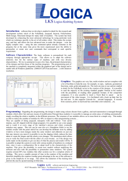


© Copyright 2026